1. INDICE/2000 DS 5. - eltacnet.com · ELT se reserva el derecho a modificarlo sin previo aviso,...
121
descarga
Transcript of 1. INDICE/2000 DS 5. - eltacnet.com · ELT se reserva el derecho a modificarlo sin previo aviso,...

desc
arga


“El presente catálogo anula y sustituye los anteriores. ELT se reservael derecho a modificarlo sin previo aviso, para mejorar las caracterís-ticas y prestaciones.En nuestra página Web puede encontrar una versión actualizada denuestros productos”.www.elt.es
“This catalogue replaces the previous ones. ELT reserves the right ofmodifying it without any notice to improve the product’s characteris-tics and performance.You can find an updated version of our catalogue on ou website”.www.elt.es

3
Quality for lightingELT as one of the leading companies in the most exigent mar-kets such as the European cover more than sixty countries andis proud to offer you this new catalogue. The widest productand services range to fill the needs of the most exigent lumi-naires manufacturers and distributors of technical and decora-tive indoor lighting, outdoor light fittings and displays.
Our engagement to continuous improvement of products andprocesses is expressed in our Quality and Environmental Poli-cy (ISO9001 and ISO14001 certifications covering the manage-ment systems). We produce under the most exigent interna-tional standards and our products meet the requirement ofENEC. A Company fully engaged to excellence in management(EFQM).
Our goal is to give full satisfaction to our customers, offeringtotal partnership to solve all your needs (pre and after salestechnical assistance, technical seminars, etc.) and sharingprofit. 243 days a year open to give service and logistic part-nership to customers and suppliers.
Our strengths are profit reinvestment policy; job creation (44%increase 1995-2002) that puts at your disposal a performingyoung and innovative team in continuous training; and, thedoubling of our turnover during the period 1995-2002. Last butnot least, a modern and multinational group of companiesgives you one single brand, ELT, guarantee of total quality. Wecombine innovation and tradition in the vanguard of serviceand technological development.
Calidad a todas lucesELT mantiene su posición de liderazgo en los mercados másexigentes, tales como el europeo y provee a más de sesentapaíses. Nuestros catálogos contienen la más amplia gamade productos y servicios para satisfacer las necesidades defabricantes de aparatos y distribuidores de iluminación inte-rior técnica y decorativa, alumbrado exterior, rotulación eimagen.
Nuestro compromiso con la mejora de nuestros productos yprocesos queda refrendado en el sistema de gestión de lacalidad y medioambiental certificado de acuerdo con lasnormas internacionales IS0 9001 e ISO 14001. Asimismo,nuestros productos cumplen las normas internacionalesaplicables (ENEC). Toda la organización se encuentracomprometida con la gestión de la calidad total (EFQM).
Nuestro objetivo es dar completa satisfacción a nuestrosclientes haciendo un acompañamiento total para darsoluciones a todas sus necesidades (atención técnica pre yposventa, seminarios técnicos, etc.) y compartiendobeneficios. Estamos permanentemente abiertos para darle elmejor servicio y le ofrecemos nuestra colaboración logísticatanto a clientes como a proveedores.
Nuestra política de reinversión constante unida a la creaciónde empleo (44% incremento 1995-2002), que nos dota de unequipo humano joven e innovador que, a través de laformación continua, presta un alto rendimiento, nos hanpermitido duplicar nuestra cifra de negocio (95/02). En suma,un grupo moderno e internacional de empresas a su serviciobajo una misma marca, ELT, garantía de calidad total. Combi-namos innovación y tradición en la vanguardia del desarrollotecnológico y el servicio.

VSB
ÍndiceIndex
4
VH
GENERAL INFORMATION
BALLASTS FOR MERCURY VAPOUR LAMPS
Built-in use, VMI typeAssemblies for built-in use, VMI-AF
Encapsulated type, VMEOutdoor type HPF-IP-54
BALLASTS FOR HIGH PRESSURESODIUM VAPOUR LAMPS
Built-in use, VSI typeBuilt-in use compact ballasts
(small dimensions)Assemblies for built-in use, VSI-AF
Assemblies for built-in use, ARCE
Encapsulated type, VSEOutdoor type HPF-IP-54
Equipments for SDX white sodium vapour lamps
BALLASTS FOR METAL HALIDE LAMPS
Built-in use, VSI and VMI typeBuilt-in use high power ballasts, VHI type
Built-in use compact ballasts (small dimensions)
Assemblies for built-in use, VSI-VMI-AFAssemblies for built-in use, ARCE
Encapsulated type, VSE-VMEOutdoor type HPF-IP-54
IP-55 boxes for high pressuresodium vapour and metal halide lamps
BALLASTS FOR LOW PRESSURESODIUM VAPOUR LAMPS
Built-in use, VSBI typeEncapsulated type, VSBE
VM
VS
6 INFORMACIÓN GENERAL
REACTANCIAS PARA LÁMPARASDE VAPOR DE MERCURIO
21 Tipo interior VMI25 Equipos completos para interior VMI-AF26 Tipo encapsulado VME71 Tipo exterior AF-IP-54
REACTANCIAS PARA LÁMPARAS DE VAPORDE SODIO A ALTA PRESIÓN
30 Tipo interior VSI34 Tipo interior compacto
(para alojamientos reducidos)35 Equipos completos para interior VSI-AF36 Equipos completos enchufables VSAP
para interior VSI-ARCE37 Tipo encapsulado VSE73 Tipo exterior AF-IP-5438 Equipos para sodio blanco SDX
REACTANCIAS PARA LÁMPARAS DE VAPORDE HALOGENUROS METÁLICOS
42 Tipo interior VSI y VMI46 Tipo interior altas potencias VHI34 Tipo interior compacto
(para alojamientos reducidos)47 Equipos completos para interior VSI-VMI-AF48 Equipos completos enchufables
Halogenuros Metálicos para interior VHI-ARCE49 Tipo encapsulado VSE-VME75 Tipo exterior AF-IP-5450 Cofres IP-55 para lámparas de V.S.A.P.
y halogenuros grandes potencias
REACTANCIAS PARA LÁMPARASDE VAPOR DE SODIO A BAJA PRESIÓN
54 Tipo interior VSBI55 Tipo exterior encapsulado VSBE
5
ÍndiceIndex
BALLASTS BI-POWER SYSTEM (2P)
Built-in use VMI-2P and VMI-2P-SM typeOutdoor type HPF-IP-54. VME-2P type
Built-in use VSI-2P typeBuilt-in use VSI-2P-SM type
Outdoor type HPF-IP-54. VSE-2P type
BALLASTS CLASS II
For mercury lampsFor high pressure sodium lamps
For metal halide lamps
CONSTANT WATTAGE AUTOTRANSFORMERBALLASTS
For H. P. Sodium lampsFor american type metal halide lamps
IGNITORS
Impulse transformer type
Superimposed or independent system
ANNEX
Electronic emergency switch
Wiring diagramsLamps and caps
Capacities for power factor correction
BranchesAgents - Distributors
IG
A
CII
VSRI
2PREACTANCIAS DE DOBLE NIVELDE POTENCIA (2P)
62 Tipo interior VMI-2P y VMI-2P-SM63 Tipo exterior IP-54. VME-2P64 Tipo interior VSI-2P65 Tipo interior VSI-2P-SM66 Tipo exterior IP-54. VSE-2P
REACTANCIAS DE CLASE II
70 Para lámparas de vapor de mercurio72 Para lámparas de vapor de sodio a alta presión74 Para lámparas de halogenuros metálicos
REACTANCIAS AUTORREGULADAS
79 Para lámparas de vapor de sodio alta presión81 Para lámparas de halogenuros metálicos
de tipo americano
ARRANCADORES
91 Tipo transformadorde impulsos o dependiente
96 Tipo superposiciónde impulsos o independiente
ANEXO
108 Conmutador electrónicode emergencia
110 Esquemas de conexionado112 Lámparas y casquillos113 Capacidades para corrección
del factor de potencia114 Delegaciones116 Representantes - Distribuidores

6
GENERAL INFORMATION
Ballats for discharge lamps
High intensity discharge lamps (H.I.D.)
These are lamps which have a gas discharge tube with much smallerdimensions than fluorescent lamps, which work at sufficient current
densities and pressures to produce the visible radiation desired.Their evolution and broad applications is due to three main reasons:
– High luminous efficiency. Great amount of lumens per watt ofpower consumed.
– They provide a compact source of light, which permits good controlof the light with the use of suitable reflector systems.
– Long life and better maintenance of the luminous flow than influorescent ones, which reduces the replacement and maintenance
costs.In accordance with the main element which characterises the
mixture of gas and the pressure in the discharge tube, the HighIntensity Discharge (H.I.D.) lamps are distinguished as follows:
1. High pressure mercury vapour lamps.2. High pressure sodium vapour lamps.
3. Mercury vapour lamps with metal additives (commonly calledmetal halides).
4. Low pressure sodium vapour lamps.These lamps, like all discharge lamps, present an impedance to thepassing of the current which decreases as the current increases, so
they cannot be connected directly to the power network without adevice to control the intensity which circulates through them. This
device is what we normally call reactance or also ballast and carriesout the following functions:
– It limits and regulates the current of the lamp.– It supplies the suitable starting current during the arc stabilising
phase.– In some cases, it provides the voltage required for the lamp to light
up.In addition, a good ballast must guarantee the following:– Good adjustment faced with supply voltage variations.
– Low heating.– Noiseless operation.
– Limitation of harmonic components in the line and lamp currents.
– Moderate own losses to achieve good efficiency.
– Dimensions which adapt to the light fitting manufacturers’ needs.
– Guarantee a long life of the lamp.Each lamp has its own particular characteristics and therefore needs
its specific ballast.
INFORMACIÓN GENERAL
Reactancias para lámparas de descarga
Lámparas de alta intensidad de descarga (H.I.D.)
Son aquellas que tienen un tubo de descarga gaseosa de dimensionesmucho más reducidas que las lámpara fluorescentes, que trabajan apresiones y densidades de corriente suficientes para producir laradiación visible deseada. Su evolución y amplia aplicación se debe atres razones principales:– Elevado rendimiento luminoso. Mayor cantidad de lúmenes porvatio de potencia consumida.– Proporcionan una fuente de luz compacta, que permite un buencontrol de la luz con el uso de sistemas reflectores adecuados.– Larga vida y mejor mantenimiento del flujo luminoso que en losfluorescentes, lo que reduce los costos de reposición ymantenimiento.De acuerdo con el elemento principal que caracteriza la mezcla de gasy la presión en el tubo de descarga, las lámparas de Alta Intensidadde Descarga (H.I.D.) se distinguen como sigue:1. Lámparas de vapor de mercurio a alta presión.2. Lámparas de vapor de sodio a alta presión.3. Lámparas de vapor de mercurio con aditivos metálicos(comúnmente llamadas de halogenuros metálicos).4. Lámparas de vapor de sodio a baja presión.Estas lámparas, como todas las de descarga, presentan unaimpedancia al paso de la corriente que disminuye a medida que éstaaumenta, por lo que no pueden ser conectadas directamente a la redde alimentación sin un dispositivo que controle la intensidad decorriente que circula por ellas. Este dispositivo es lo quehabitualmente llamamos reactancia o también balasto y realiza lassiguientes funciones:– Limita y regula la corriente en la lámpara.– Suministra la corriente adecuada de arranque durante la fase deestabilización del arco.– En algunos casos, suministra la tensión necesaria para el encendidode la lámpara.Además, una buena reactancia debe garantizar lo siguiente:– Buena regulación frente a las variaciones de la tensión dealimentación.– Bajo calentamiento.– Funcionamiento sin ruido.– Limitación de componentes armónicos en las corrientes de línea yde lámpara. – Pérdidas propias moderadas para lograr un buen rendimiento delconjunto.– Dimensiones apropiadas a las necesidades de los fabricantes deluminarias.– Garantizar al máximo la vida de la lámpara.Cada lámpara tiene unas características particulares y por lo tanto,necesita una reactancia específica.
7
For some of them, like the mercury vapour lamps, the networkvoltage (220-240V) is sufficient to ignite the lamp. For others, high
voltage must be available to achieve the ignition. This high voltagecan be supplied by the autotransformer type ballast, as in the case
of the low pressure sodium, or by additional elements such asstarters which provide simple or multiple, high voltage pulses,
required for the ionisation of the gas and ignition of the lamp, whichis the case of high pressure sodium and metal halide lamps.
Identification of the lamps
To solve the difficulty in identifying each type of lamp according tothe manufacturer, the ILCOS (International Lamp Coding System) is
being implemented. This is set out in the publication of standard CEI1239 of 1993, which defines the lamp regardless of who
manufactures it.The initials which identify each lamp are the following:
Q High-pressure mercury lampsQT Tubular clear lamps
QE Diffuse coated Elliptical lampQC Clear elliptical lamp
QG Globular, coatedQR Reflector type lampQB Self-ballasted lamp
QBR Self-ballasted lamp with reflector
S High-pressure sodium lampST Tubular clear lamp
SE Elliptical diffuse coated lampSC Elliptical clear lamp
SD Double-ended clear lampSR Reflector type lamp
S-Q For high-pressure mercury equipmentS-M Colour-improved lamp
S-H High colour rendering indexS-T Twin arc tube lamp
M Metal halide lampsMT Tubular clear lamp
ME Diffuse-coated elliptical or BT bulbMC Clear elliptical or BT bulb
MR Reflector type lampMD Clear double-ended lamp
MN Double-ended lamp without outer bulb
L Low-pressure sodium lampLS Single-capped lamp
LD Double-capped lampLSE Single-capped lamp of the E-type
Para algunas de ellas, como las de vapor de mercurio, es suficientecon la tensión de red (220-240V), para encender la lámpara. Paraotras, es necesario disponer de alta tensión para lograr el encendido.Esta alta tensión puede ser suministrada por la reactancia de tipoautotransformador, como en el caso del sodio a baja presión, o porelementos adicionales como son los arrancadores, que proporcionanimpulsos de alta tensión, simples o múltiples, necesarios para laionización del gas y arranque de la lámpara, cual es el caso de laslámparas de sodio a alta presión y de los halogenuros metálicos.
Identificación de las lámparas
Como solución a la dificultad para la identificación de cada tipo delámpara según el fabricante, se está implantando el sistema ILCOS(International Lamp Coding System), expuesto en la publicación de lanorma CEI 1239 de 1993, que permite una definición de la lámparaindependientemente del fabricante de la misma.Las siglas que identifican a cada lámpara Son las siguientes:
Q Lámparas de Vapor de Mercurio a alta presiónQT Lámpara Tubular claraQE Lámpara Elíptica difusaQC Lámpara elíptica ClaraQG Lámpara GlobularQR Lámpara ReflectorQB Lámpara con BalastoQBR Lámpara con Balasto y Reflector
S Lámparas de Vapor de Sodio a alta presiónST Lámpara Tubular claraSE Lámpara Elíptica difusaSC Lámpara elíptica ClaraSD Lámpara clara Doble portalámparasSR Lámpara con ReflectorS-Q Lámpara para equipo de Vapor de MercurioS-M Lámpara de color MejoradoS-H Lámpara de Alto rendimiento de colorS-T Lámpara de doble tubo de descarga
M Lámparas de Halogenuros metálicosMT Lámpara Tubular claraME Elíptica difusa o ampolla BTMC Elíptica Clara o ampolla BTMR Lámpara con ReflectorMD Lámpara clara Doble portalámparasMN Doble portalámparas sin ampolla exterior
L Lámparas de Vapor de Sodio a baja presiónLS Lámpara Simple portalámparasLD Lámpara Doble portalámparasLSE Simple portalámparas del tipo E

8
Ballasts for discharge lamps
Depending on the network voltage available, their shape andoperating characteristics, the most commonly used types are the
following:– Series or simple impedance ballasts.
– Autotransformer ballasts.– Self-regulating ballasts.
– Bi-power system ballasts.
Simple impedance ballasts
This is used when the network voltage is sufficient to ensure theignition and stable operation of the lamp. It is the most simple,
economical, smallest and with least losses, so it is most commonlyused system. It consists of an inductance connected in series to the
lamp which limits and regulates the current.It must be taken into account that certain LP sodium and metal
halide lamps cannot operate with this type of ballast.The power adjustment faced with variations in the network voltageis not very good, so a variation of 10% causes power variations in
lamps of 20 to 25%. Therefore, it must only be used in circuits wherenetwork voltage fluctuations do not exceed ± 5%.
Autotransformer ballasts
When the network voltage is not sufficient to ignite the lamp, theuse of autotransformer ballasts (magnetic leakage autotransformer)
is required. They operate by raising the voltage to the exact value tostart and maintain the arc of the lamp.
This type of ballast, like the series ones, has low power adjustmentin lamp.
The correction of the power factor will always be in parallel and wewill have to use large capacity capacitors.
Reactancias para lámparas de descarga
Dependiendo de la tensión de red disponible, su forma constructiva ycaracterísticas de funcionamiento, los tipos más utilizados son lossiguientes:– Reactancias serie o simple impedancia.– Reactancias autotransformadoras.– Reactancias autorreguladoras.– Reactancias de doble nivel de potencia.
Reactancia de simple impedancia
Se usa cuando la tensión de red es suficiente para arrancar ymantener estable el arco de la lámpara. Es la más sencilla,económica, de menor tamaño y de pérdidas más reducidas, por lo quees el sistema más usado. Consiste en una inductancia en serie con lalámpara, que limita y regula la corriente en la misma.Debe tenerse en cuenta que determinadas lámparas de sodio BP yhalogenuros metálicos no pueden funcionar con este tipo de reactancia.La regulación de potencia frente a las variaciones de la tensión de lared no es muy buena, de tal forma que una variación del 10%ocasiona variaciones de potencia en lámpara del 20 al 25%. Por ello,sólo debe utilizarse en circuitos donde las fluctuaciones de tensión dered no superen el ± 5%.
Reactancias autotransformadoras
Cuando la tensión de red es insuficiente para lograr el arranque de lalámpara, se hace necesario la utilización de reactanciasautotransformadoras (o autotransformador de dispersión), las cualeselevan la tensión al valor preciso para arrancar y mantener el arco enla lámpara.Este tipo de reactancia, al igual que las de serie,tienen baja regulación de potencia en lámpara.La corrección del factor de potencia será siempre enparalelo y habremos de utilizar para ellocondensadores de gran capacidad.
R
C~
N
F
REACTANCIAEN SERIE
F
N
C P
S
~REACTANCIAAUTOTRANSFORMADORA
9
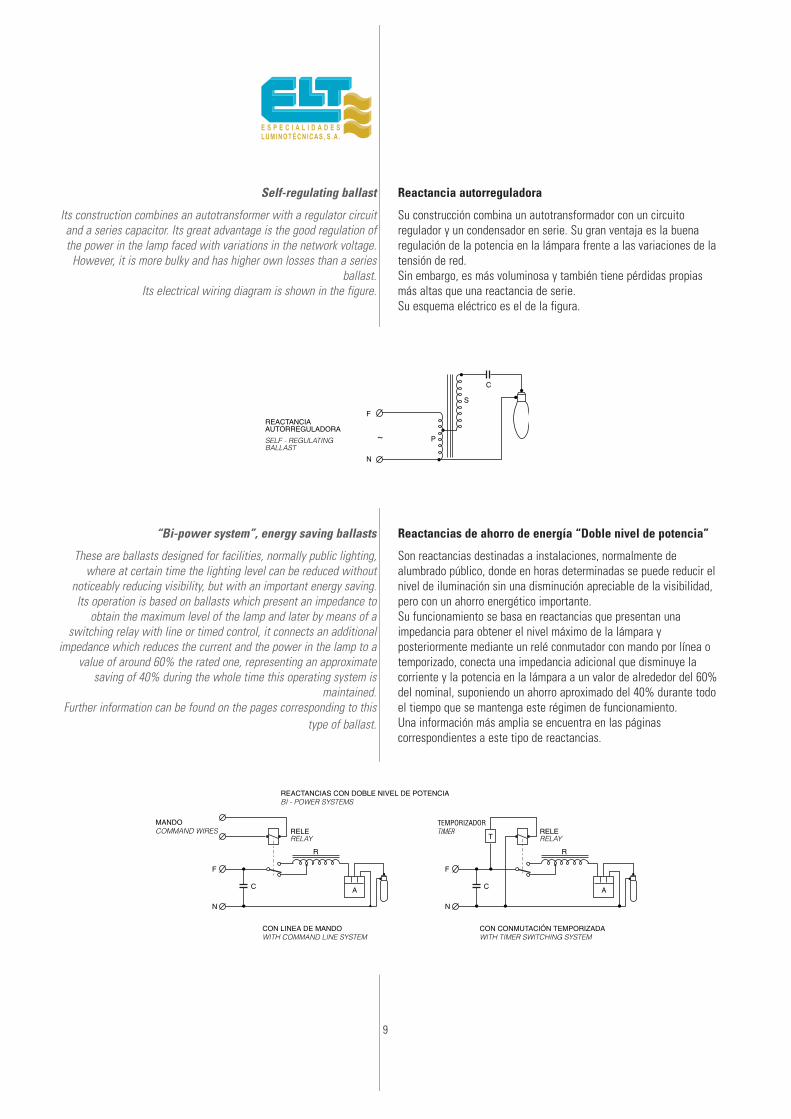
Self-regulating ballast
Its construction combines an autotransformer with a regulator circuitand a series capacitor. Its great advantage is the good regulation ofthe power in the lamp faced with variations in the network voltage.
However, it is more bulky and has higher own losses than a seriesballast.
Its electrical wiring diagram is shown in the figure.
“Bi-power system”, energy saving ballasts
These are ballasts designed for facilities, normally public lighting,where at certain time the lighting level can be reduced without
noticeably reducing visibility, but with an important energy saving.Its operation is based on ballasts which present an impedance to
obtain the maximum level of the lamp and later by means of aswitching relay with line or timed control, it connects an additional
impedance which reduces the current and the power in the lamp to avalue of around 60% the rated one, representing an approximate
saving of 40% during the whole time this operating system ismaintained.
Further information can be found on the pages corresponding to thistype of ballast.
Reactancia autorreguladora
Su construcción combina un autotransformador con un circuitoregulador y un condensador en serie. Su gran ventaja es la buenaregulación de la potencia en la lámpara frente a las variaciones de latensión de red.Sin embargo, es más voluminosa y también tiene pérdidas propiasmás altas que una reactancia de serie.Su esquema eléctrico es el de la figura.
Reactancias de ahorro de energía “Doble nivel de potencia”
Son reactancias destinadas a instalaciones, normalmente dealumbrado público, donde en horas determinadas se puede reducir elnivel de iluminación sin una disminución apreciable de la visibilidad,pero con un ahorro energético importante.Su funcionamiento se basa en reactancias que presentan unaimpedancia para obtener el nivel máximo de la lámpara yposteriormente mediante un relé conmutador con mando por línea otemporizado, conecta una impedancia adicional que disminuye lacorriente y la potencia en la lámpara a un valor de alrededor del 60%del nominal, suponiendo un ahorro aproximado del 40% durante todoel tiempo que se mantenga este régimen de funcionamiento.Una información más amplia se encuentra en las páginascorrespondientes a este tipo de reactancias.
F F
MANDORELERELE
T
N N
A A
RR
C C
CON LINEA DE MANDO
REACTANCIAS CON DOBLE NIVEL DE POTENCIA
CON CONMUTACIÓN TEMPORIZADA
F
N
C
P
S
~
REACTANCIAAUTORREGULADORA
10
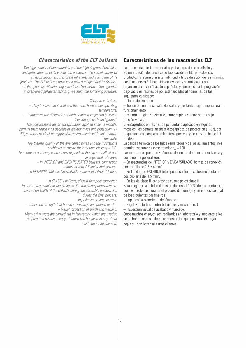
Characteristics of the ELT ballasts
The high quality of the materials and the high degree of precisionand automation of ELT’s production process in the manufactures of
all its products, ensures great reliability and a long life of itsproducts. The ELT ballasts have been tested an qualified by Spanishand European certification organisations. The vacuum impregnation
in oven-dried polyester resins, gives them the following qualities:
– They are noiseless.– They transmit heat well and therefore have a low operating
temperature.– It improves the dielectric strength between loops and between
low voltage parts and ground.The polyurethane resins encapsulation applied in some models,
permits them reach high degrees of leaktightness and protection (IP-67) so they are ideal for aggressive environments with high relative
humidity.The thermal quality of the enamelled wires and the insulations
enable us to ensure their thermal class tw = 130.The network and lamp connections depend on the type of ballast and
as a general rule ares:– In INTERIOR and ENCAPSULATED ballasts, connection
terminals with 2.5 and 4 mm2 screws.– In EXTERIOR-outdoors type ballasts, multi-pole cables, 1.5 mm2.
– In CLASS II ballasts, class II four-pole connector.To ensure the quality of the products, the following parameters arechecked on 100% of the ballasts during the assembly process and
during the final process:– Impedance or lamp current.
– Dielectric strength test between windings and ground (earth).– Visual inspection of finish and marking.
Many other tests are carried out in laboratory, which are used toprepare test results, a copy of which can be given to any of our
customers requesting it.
Características de las reactancias ELT
La alta calidad de los materiales y el alto grado de precisión yautomatización del proceso de fabricación de ELT en todos susproductos, asegura una alta fiabilidad y larga duración de las mismas.Las reactancias ELT han sido ensayadas y homologadas pororganismos de certificación españoles y europeos. La impregnaciónbajo vacío en resinas de poliéster secadas al horno, les da lassiguientes cualidades:– No producen ruido.– Tienen buena transmisión del calor y, por tanto, baja temperatura defuncionamiento.– Mejora la rigidez dieléctrica entre espiras y entre partes bajotensión y masa.El encapsulado en resinas de poliuretano aplicado en algunosmodelos, les permite alcanzar altos grados de protección (IP-67), porlo que son idóneas para ambientes agresivos y de elevada humedadrelativa.La calidad térmica de los hilos esmaltados y de los asilamientos, nospermite asegurar su clase térmica tw = 130.Las conexiones para red y lámpara dependen del tipo de reactancia ycomo norma general son:– En reactancias de INTERIOR y ENCAPSULADO, bornes de conexióncon tornillo de 2,5 y 4 mm2.– En las de tipo EXTERIOR-Intemperie, cables flexibles multipolarescon cubierta de, 1,5 mm2.– En las de clase II, conector de cuatro polos clase II.Para asegurar la calidad de los productos, el 100% de las reactanciasson comprobadas durante el proceso de montaje y en el proceso finalde los siguientes parámetros:– Impedancia o corriente de lámpara.– Rigidez dieléctrica entre bobinados y masa (tierra).– Inspección visual de acabado y marcado.Otros muchos ensayos son realizados en laboratorio y mediante ellos,se elaboran los tests de resultados de los que podemos entregarcopia si lo solicitan nuestros clientes.
11
Recommendationsfor a correct installation
To obtain a safe, efficient and lasting installation and also theoptimal lifetime of HID lamps it is essential to take into account the
following aspects.• Correct choice and compatibility of the components (choke,
ignitor, capacitor) to drive the selected lamp in accordancewith the mains voltage and frequency.
• The location of the control gear must define its protectionindex against the ingress of foreign bodies, dust and
moisture.• The temperature on the different components when mounted
in closed compartments such as luminaires, cabinets, boxes.The maximum permissible temperature of each component
will be not exceeded.• System Cabling. In order to select the cable for an
installation some points must be considered. The cross-section of the cable have to be rated in accordance with the
maximum current. In addition, cable insulation mustwithstand the operating voltage.
• Servicing and replacement operations must be executed withthe mains power supply disconnected and carried out by
qualified staff following strictly the manufacturerrecommendations and the applicable regulations on electrical
installations.
Recomendaciones para una correctainstalaciónPara lograr una instalación segura, eficaz y duradera, e incluso elfuncionamiento y vida óptimos en las lámparas de H.I.D. deben teneren cuenta una serie de puntos fundamentales, que son:• Elección del equipo auxiliar (reactancia + arrancador +
condensador) adecuado para la lámpara con la que ha defuncionar, la tensión y frecuencia de la línea de alimentación y lacompatibilidad entre los mismos.
• Lugar de instalación para que el equipo auxiliar esté fabricado conel grado de protección eléctrica y ambiental necesarios.
• Verificar que las temperaturas alcanzadas por los componentes enel lugar o habitáculo de instalación (luminaria, cofre, armario, etc.)no sobrepasan los límites indicados para cada uno de ellos.
• Utilizar cables de instalación con la sección adecuada a laintensidad de corriente que por ellos va a circular y de aislamientonecesario para las tensiones a soportar.
• Las operaciones de mantenimiento y reposición de componentes,siempre deben ser realizadas sin tensión de alimentación, y porpersonal cualificado, siguiendo rigurosamente las instruccionesdadas sobre el producto y los reglamentos vigentes de instalacióneléctricas.

12
Types of ELT ballasts. ApplicationsAplicaciones de las mismas
INTERIOR type-Ballasts for built in useNamed with initials: VMI, VSI, VHI, VMMI and VSBI. To be installed
in fittings, boxes, cabinets, etc. That is, with an additional protectionagainst water, dust, humidity.
Never install in the foot, outdoors or places where there is a lot ofwater condensation.
ENCAPSULATED typeIdentified with the initials: VME, VSE, VHE and VSBE. These are
ballasts with 6.6. polyamide protection casing with fibreglass andpolyurethane resin encapsulation for greater protection against dust,
humidity and rain.
EXTERIOR-High Factor-Outdoors type IP-54Identified with the initials: VME-AF, VSE-AF, VHE-AF and VSBE-AF.These are ballasts with protective casing and polyurethane resin-
encapsulation, with the starter, capacitors for power factorcorrection and the switching relay on the inside in the cases of twin
power level (2P).Designed to be installed outdoors.
The casings are made of extruded and anodised aluminium or 6.6polyamide with grey fibreglass. In both types of casing they have an
easily removable lower cover which enables the auxiliarycomponents to be changed or replaced.
The outputs are with coloured hoses indicating connection to line,lamp and control.
Class II ballastIdentified with the initials: VMI, VSI, VME and VSE---C2. These are
ballasts with complete built-in equipment where all the parts areprotected by an insulating and long-lasting casing which presentspossible contacts with active parts. Three-pole connector for LINE
AND LAMP, also class II.
Tipos de reactancias ELT.Aplicaciones de las mismas
Tipo INTERIOR-Reactancias a incorporarDenominadas con las siglas: VMI, VSI, VHI, VMMI y VSBI. Parainstalación en luminarias, cajas, armarios, etc. Es decir, con unaprotección adicional al agua, polvo, humedad.No instalar nunca a pie de báculo, intemperie o lugares donde hayafuertes condensaciones de agua.
Tipo ENCAPSULADOIdentificadas con las siglas: VME, VSE, VHE y VSBE. Son reactanciascon envolventes de protección de poliamida 6.6 con fibra de vidrio yencapsuladas en resinas de poliuretano para mayor protección contrapolvo, humedad y lluvia.
Tipo EXTERIOR -Alto Factor-Intemperie IP-54Identificadas con las siglas: VME-AF, VSE-AF, VHE-AF y VSBE-AF. Sonreactancias con envolventes de protección y encapsuladas en resinasde poliuretano, alojando en su interior el arrancador, loscondensadores para corrección del factor de potencia y el reléconmutador en los casos de doble nivel de potencia (2P).Previstas para montaje a la intemperie.Los envolventes son de poliamida 6.6 con fibra de vidrio, de color gris.Las salidas son con cables manguera de colores indicativos delconexionado a línea, lámpara y mando.
Reactancias de Clase IIIdentificadas con las siglas: VMI, VSI, VME y VSE---C2. Sonreactancias con equipo completo incorporado en las que todas suspartes están protegidas por una envolvente de poliamida 6.6 con fibrade vidrio, de color gris aislante y duradera, que evita posiblescontactos con partes activas. Con conector tetrapolar para LÍNEA YLÁMPARA también de clase II.
13
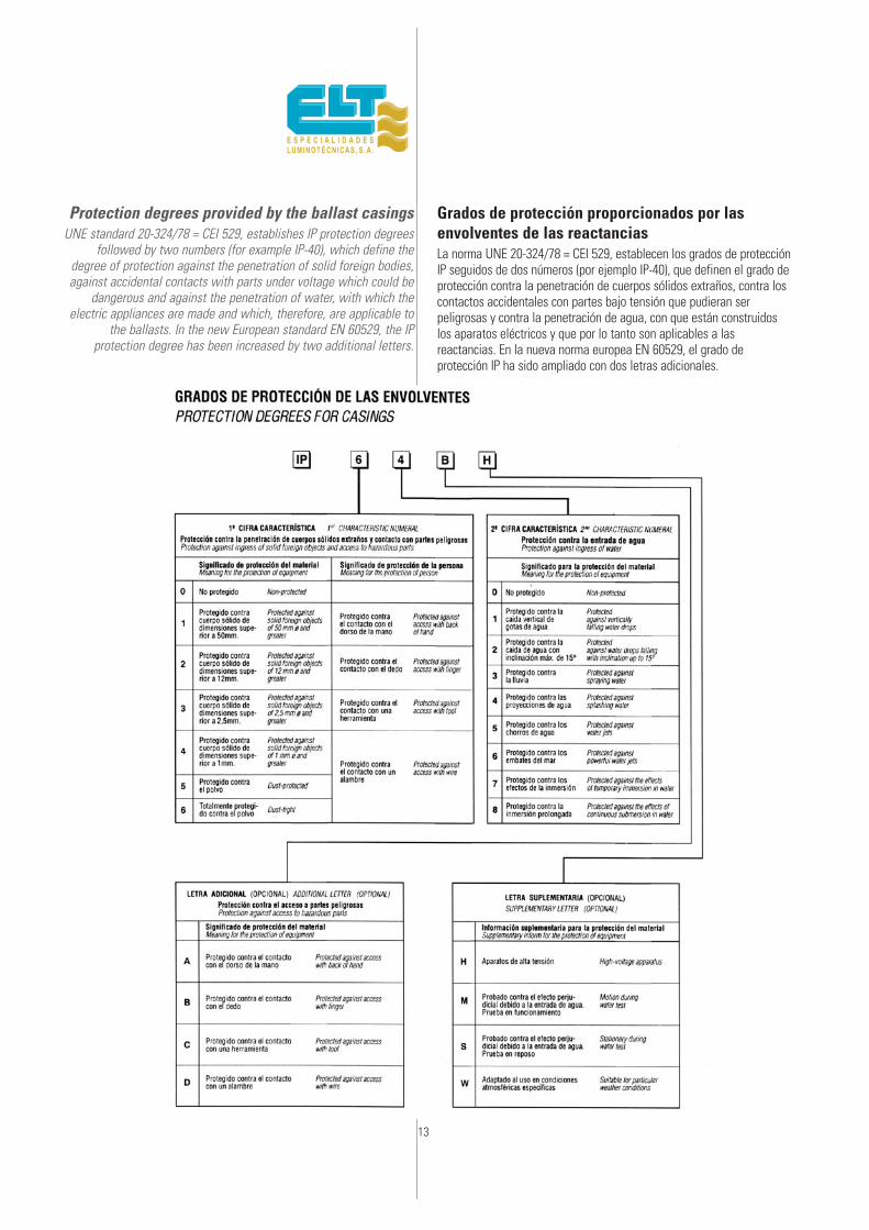
Protection degrees provided by the ballast casingsUNE standard 20-324/78 = CEI 529, establishes IP protection degrees
followed by two numbers (for example IP-40), which define thedegree of protection against the penetration of solid foreign bodies,against accidental contacts with parts under voltage which could be
dangerous and against the penetration of water, with which theelectric appliances are made and which, therefore, are applicable to
the ballasts. In the new European standard EN 60529, the IPprotection degree has been increased by two additional letters.
Grados de protección proporcionados por lasenvolventes de las reactanciasLa norma UNE 20-324/78 = CEI 529, establecen los grados de protecciónIP seguidos de dos números (por ejemplo IP-40), que definen el grado deprotección contra la penetración de cuerpos sólidos extraños, contra loscontactos accidentales con partes bajo tensión que pudieran serpeligrosas y contra la penetración de agua, con que están construidoslos aparatos eléctricos y que por lo tanto son aplicables a lasreactancias. En la nueva norma europea EN 60529, el grado deprotección IP ha sido ampliado con dos letras adicionales.

14
Classes of protection of electric appliances
Class 0 appliances
Appliances where the protection against electric discharges consistsof one main insulation.
No terminal is foreseen for connection of the protection conductor,so that the potencial will go to earth in the case of a fault in the
main insulation.The protection against the lack of electric insulation depends then on
the surroundings, which must be insulating (for example, the ground).
Class I appliances
Appliance which has at least one main insulation in all its parts andwhich has a terminal or earth connection, to bypass to it the
potencial which the accessible conductor parts may be submitted to,in the case of a fault in the main insulation.
They must be associated with a suitable cut-out and protection device.
Class II appliances
Appliance where the protection against electric discharges not onlyresides in the main insulation, but it has a double insulation or
reinforced insulation in all its parts and it does not have a device forearth connection.
It usually has a long-lasting and practically continuous, insulatingcasing, which surrounds it so that the accessible metal parts cannot
be under voltage, in the case of functional insulation.
Class III appliances
Appliances where the protection against electric discharges consistsof the supply at Very Low Safety Voltage (MBTS) and where voltages
over 50V are not generated.
Protection of people against electric discharges
(The numbering of the protection classes does not imply anyhierarchy of value)
Clases de protección de los aparatoseléctricosAparatos de Clase O
Aparato en el que la protección contra las descargas eléctricasconsiste en un aislamiento principal.No tiene previsto borne para conexión del conductor de protección,para que el potencial vaya a tierra en caso de fallo del aislamientoprincipal.La protección contra la falta de aislamiento eléctrico queda entoncessupeditada al entorno, que debe ser aislante (por ejemplo, el suelo).
Aparatos de Clase I
Aparato que tiene, como mínimo, un aislamiento principal en todas suspartes y que está provisto de un borne o de una toma de tierra, paraderivar a ésta el potencial a que puedan quedar sometidas las partesconductoras accesibles, en caso de fallo del aislamiento principal.Deben estar asociados a un dispositivo de protección y corte adecuado.
Aparatos de Clase II
Aparato en el que la protección contra las descargas eléctricas nosólo reside en el aislamiento principal, sino que tiene en todas suspartes un doble aislamiento o un aislamiento reforzado y que no estáprovisto de un dispositivo para su puesta a tierra.Suele tener una envolvente duradera, y prácticamente continua dematerial aislante que lo rodea de forma que no puedan quedar bajotensión las partes metálicas accesibles, en caso de fallo delaislamiento principal.
Aparatos de Clase III
Aparatos en los que la protección contra las descargas eléctricasconsiste en la alimentación de Muy Baja Tensión de Seguridad(MBTS) y en los que no se generan tensiones superiores a los 50V.
Protección de las personas contra las descargas eléctricas
(La numeración de las clases de protección no implica ningunajerarquía de valor)
MATERIAL
NIVEL DEPROTECCIÓNPROTECTIONDEGREE
Primero
Segundo
Tierra
Aislamientoprincipal
Aislamientocomplementario
Local seco y noconductor.
Puesta a tierray dispositivo decorte afín
Aislamientoduplicado oreforzado
Alimentaciónde seguridad
Aislamientoprincipal
Aislamientoprincipal
Aislamientoprincipal
Tensión inferiora 50V MBTS
Clase 0Class
Clase IClass
Clase IIClass
Clase IIIClass
III

15
Approvals of the ballasts
All the ELT ballasts are manufactured according to the national and international standards corresponding to each product. As aresult, many of them have been tested and qualified by Spanish,
European and even American certification organisations, such as thefollowing:
ELT has obtained the EN-EC certification for its products, too. Thiscertification is granted by AENOR and established by the CENELEC,
being recognised by the European countries signing the LUM-AGREEMENT, and including all the certifications of the respective
countries, enabling free circulation of the products bearing thiscertification in all the countries.
Standards of reference
The standards which govern the safety and operation of the ballastsfor High Intensity Discharge (H.I.D.) lamps and according to which all
ELT products are manufactured, are:UNE-EN 61347-1 Devices for lamps - part. 1:
general and safety requirements.UNE-EN 61347-2-9 Devices for lamps -part 2-9:
special requirements for ballasts for discharge lamps(except fluorescent lamps).
UNE-EN 60923 Ballasts for discharge lamps (excluding fluorescenttubular lamps). Performance requirements.
ANSI C82-4 Ballasts for high intensity discharge and low pressuresodium lamps.
UNE-EN 60662 High pressure sodium vapour lamps.UNE-EN 61167 Metal halide lamps.
UNE-EN 60188 High pressure mercury vapour lamps.UNE-EN 60192 Low pressure sodium vapour lamps.
UNE-EN 60598 Luminaires.
Modification of the supply voltage 220/380to 230/400V
The unification proposal to 230/400V, as rating value of the supplyvoltage for the European Community, was approved by the CENELEC
on 21-10-1988. Each member country of the CENELEC, will assess
Homologaciones de las reactancias
Todas las reactancias ELT son fabricadas según las normas nacionalese internacionales correspondientes a cada producto. Comoconsecuencia, muchas de ellas han sido ensayadas y homologadaspor organismos de certificación españoles, europeos e inclusoamericanos, como los siguientes:
ELT ha obtenido para sus productos también la marca EN-EC,concedida por AENOR. Marca que fue establecida por el CENELEC yreconocida por los países europeos firmantes del acuerdo LUM-AGREEMENT, y que engloba todas las marcas de los paísesrespectivos, permitiendo en todos ellos la libre circulación de losproductos portadores de la misma.
Normas de referencia
Las normas que regulan la seguridad y el funcionamiento de lasreactancias para lámparas de Alta Intensidad de Descarga (H.I.D.) ysegún las cuales se fabrican todos los productos ELT, son:UNE-EN 61347-1 Aparatos auxiliares para lámparas -parte 1:
requisitos generales y de seguridad.UNE-EN 61347-2-9: Aparatos auxiliares para lámparas -parte 2-9:
requisitos particulares para reactancias paralámparas de descarga (exc. fluorescentes).
UNE-EN 60923 Reactancias para lámparas de descarga(excepto lámparas tubulares fluorescentes).Prescripciones de funcionamiento.
ANSI C82.4 Reactancias para lámparas de alta intensidadde descarga y sodio baja presión.
UNE-EN 60662 Lámparas de vapor de sodio a alta presión.UNE-EN 61167 Lámparas de halogenuros metálicas.UNE-EN 60188 Lámparas de vapor de mercurio a alta presión.UNE-EN 60192 Lámparas de vapor de sodio a baja presión.UNE-EN 60598 Luminarias.
Modificación de la tensión de alimentación220/380 a 230/400V
La propuesta de unificación a 230/400V, como valor nominal de latensión de alimentación para la Comunidad Europea, fue aprobada por
16
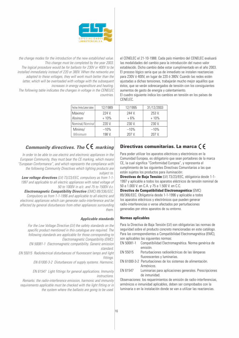
the change modes for the introduction of the new established value.This change must be completed by the year 2003.
The logical procedure would be for ballasts for 230V or 400V to beinstalled immediately instead of 220 or 380V. When the networks are
adapted to these voltages, they will work much better than thelatter, which will be overloaded with voltage with the subsequent
increases in energy expenditure and heating.The following table indicates the changes in voltage in the CENELEC
countries.
Community directives. The ce marking
In order to be able to use electric and electronic appliances in theEuropean Community, they must bear the CE marking, which means
“European Conformance”, and which represents the compliance withthe following Community Directives which lighting products are
subject to.Low voltage directives (LV) 73/23/EEC, compulsory as from 1-1-1997 and applicable to all electric appliances with rated voltage of
50 to 1000V in a/c. and 75 to 1500V d.c.Electromagnetic Compatibility Directive (EMC) 89/336/EEC.
Compulsory as from 1-1-1996 and applicable to all electric andelectronic appliances which can generate radio-interference and beaffected by general disturbances from other appliances surrounding
them.
Applicable standards
For the Low Voltage Directive (LV) the safety standards on thespecific product mentioned in this catalogue are required. Thefollowing standards are applicable for those corresponding to
Electromagnetic Compatibility (EMC):EN 50081-1 Electromagnetic compatibility. Generic emission
standard.EN 55015 Radiolectrical disturbances of fluorescent lamps and light
fittings.EN 61000-3-2 Disturbances of supply systems. Harmonic.
EN 61547 Light fittings for general applications. Immunityinstructions.
Remarks: the radio-interference emission, harmonic and immunityrequirements applicable must be checked with the light fitting or in
the system where the ballasts are going to be used.
el CENELEC el 21-10-1988. Cada país miembro del CENELEC evaluarálas modalidades del cambio para la introducción del nuevo valorestablecido. Dicho cambio debe estar cumplimentado en el año 2003.El proceso lógico sería que ya de inmediato se instalen reactanciaspara 230V ó 400V, en lugar de 220 ó 380V. Cuando las redes esténajustadas a dichas tensiones, trabajarán mucho mejor aquéllos queéstos, que se verán sobrecargados de tensión con los consiguientesaumentos de gasto de energía y calentamiento.El cuadro siguiente indica los cambios en tensión en los países deCENELEC.
Directivas comunitarias. La marca
Para poder utilizar los aparatos eléctricos y electrónicos en laComunidad Europea, es obligatorio que sean portadores de la marcaCE, la cual significa “Conformidad Europea”, y representa elcumplimiento de las siguientes Directivas Comunitarias a las queestán sujetos los productos para iluminación:Directivas de Baja Tensión (LV) 73/23/EEC, obligatoria desde 1-1-1997 y aplicable a todos los aparatos eléctricos de tensión nominal de50 a 1.000 V. en C.A. y 75 a 1.500 V. en C.C.Directiva de Compatibilidad Electromagnética (EMC)89/366/EEC. Obligatoria desde 1-1-1996 y aplicable a todoslos aparatos eléctricos y electrónicos que pueden generarradio-interferencias o verse afectados por perturbacionesgeneradas por otros aparatos de su entorno.
Normas aplicables
Para la Directiva de Baja Tensión (LV) son obligatorias las normas deseguridad sobre el producto concreto mencionadas en este catálogo.Para las correspondientes a Compatibilidad Electromagnética (EMC),son aplicables las siguientes normas:EN 50081-1 Compatibilidad Electromagnética. Norma genérica de
emisión.EN 55015 Perturbaciones radioeléctricas de las lámparas
fluorescentes y luminarias.EN 61000-3-2 Perturbaciones de los sistemas de alimentación.
Armónicos.EN 61547 Luminarias para aplicaciones generales. Prescripciones
de inmunidad.Observaciones: los requerimientos de emisión de radio-interferencias,armónicos e inmunidad aplicables, deben ser comprobados con laluminaria o en la instalación donde se van a utilizar las reactancias.
Fechas límite/Latest dates
Máximo/Maximum
12/1989224 V.+ 10%
244 V.+ 6%
253 V.+ 10%
Mínimo/Minimum
–10%198 V.
–10%207 V.
–10%207 V.
12/1995 31/12/2003
Nominal/Nominal 220 V. 230 V. 230 V.

17
Quality guarantee in ELT products
In order to guarantee the quality and compliance with all the productspecifications, ELT has implemented a quality assurance system
which controls all the purchase materials, manufacturing processesand final product.
The whole system organisation: structure, responsabilities,procedures and methods or control patterns, are contained in a
Quality Assurance Manual, prepared according to EN-ISO 29000standards, equivalent to ISO-9000 standards. ELT’s Quality Assurance
System was audited and approved in February 1993 by AENOR, inaccordance with EN-ISO 29002 standard, obtaining the Company
Register Certificate n.º ER-026/2/93.The quality system is extended on 1999-03-18 o provide for the product design in accordance
with EN-ISO 9001:1994 standard,obtaining the Company Register Certificate N.ER-026/93.
Updated in 2003 and according to standard UNE-EN-ISO 9001:2000with Registered Company certificate number ER-0026/1993.
Marks and indications
Apart from the electric features, a series of indications are printedon the ballasts, which should be studied in order to use them
correctly, thus obtaining maximum electric, safety and durationpossibilities.
Tw This is the maximum temperature at which the ballast windingscan operate constantly under normal conditions, at their rated
voltage and frequency, to ensure an average life of 10 years. Anyincreases or decreases in the temperature of the windings affect
their life span, as shown in the enclosed chart.
∆t Heating of the windings of a ballast over the ambienttemperature where it is installed, operating under nomal conditions
and at rated voltage and frequency.ta Maximum ambient temperature at which a ballast can be
operated under normal conditions.
Garantía de calidad en los productos ELTPara garantizar la calidad y mantenimiento de todas lasespecificaciones de los productos, ELT tiene implantado un sistema deaseguramiento de la calidad que controla todos los materiales decompra, procesos de fabricación y producto final.El conjunto de toda la organización del sistema: estructura,responsabilidades, procesos, y métodos o pautas de control, se hallancontenidos en un Manual de Aseguramiento de la Calidad, elaboradode acuerdo con las normas EN-ISO 29000, equivalente a las normasISO-9000. El sistema de Aseguramiento de la Calidad de ELT fueauditado y aprobado en febrero de 1993 por AENOR, conforme a lanorma EN-ISO 29002, obteniendo el Certificado de EmpresaRegistrada con el n.º ER-026/2/93.Fue ampliado incluyendo también el “Diseño del producto” en fecha18-03-1999 según norma UNE-EN-ISO 9001:1994 y con lo que elCertificado de Empresa Registrada es el Nº ER-0026/1/93.
Renovado en 2003 y acorde a a la norma UNE-EN-ISO 9001:2000 conel certificado de Empresa Registrada nº ER-0026/1993.
Marcas e indicacionesLas reactancias, además de las características eléctricas, llevanimpresas una serie de indicaciones que conviene conocer para hacerel uso adecuado de las mismas, obteniéndose así las máximasprestaciones eléctricas, de seguridad y duración.
Tw Es la temperatura máxima a la cual pueden funcionarconstantemente los bobinados de una reactancia en condicionesnormales, a su tensión y frecuencia nominales, para asegurar una vidamedia de 10 años. Los aumentos o disminuciones de la temperaturade los bobinados tienen una influencia en la vida de los mismos,según se refleja en el gráfico adjunto.
∆t Calentamiento de los bobinados de una reactancia sobre latemperatura ambiente en la que está instalada, funcionando encondiciones normales y a tensión y frecuencia nominales.ta Temperatura de ambiente máxima a la que puede funcionar unareactancia en condiciones normales.
º
18
This is determined by ta = tw–∆t
Example: tw = 130 ∆t = 60 ta = 70°C
Losses: Self-consumed power. If no other way is indicated, this value is measured with rated voltage and frequency and with
the windings at a temperature of 25°C.
λλ: Power Factor is obtained by the following formula.
λ = Line powerLine voltage x line current
: Self-certifying marking which indicates conformity with the European Directives LV and EMC.
Care for the Environment.Environmental Management System.
With his aim of continual improvement ELT has implemented anenvironmental management system EN ISO-14001. Care for the
environment is a firmly commitment of all the members of thecompany.
The main objectives of the environmental policy are:
• Elimination of any hazardous waste.
• Reduction in the emission of gases into theatmosphere and noise prevention.
• Reduction of non hazardous waste.
• Recycling of materials and packing.
• Energy saving in the manufacturing process.
The fulfillment of these objectives is expectedby means of:
The design of more efficient products, the useof less pollutant resources and raw materials.
The introduction into the production processof more efficient energy technologies, the
environmental sensitizing of the staff and theextension of this policy to customers and
suppliers. These actions pretend support asustainable development and a use more
reasonable of the natural resources.
The implementation of the environmentalmanagement system has been certified by
AENOR according to EN-ISO-14001 standard.The AENOR certificate N.CGM-00/041 was
issued on 2000-03-14.
Viene determinada por ta = tw–∆t
Ejemplo: tw = 130 ∆t = 60 ta = 70°C
Pérdidas: Potencia autoconsumida. Si no se indica de otra forma,este valor está medido con voltaje y frecuencia nominales y con losbobinados a una temperatura de 25°C.
λλ: Factor de potencia, se obtiene por la siguiente fórmula.
λ = Potencia de líneaTensión de línea x Corriente de línea
: Marca de autocertificación que declara la conformidad con lasDirectivas Europeas LV y EMC.
Protección del Medio Ambiente.Sistema de Gestión Medio Ambiental.
ELT en su deseo de mejora continua, ha implantado el Sistema deGestión Medioambiental (SGMA), según la norma UNE-EN-ISO-14001,con el compromiso firme de toda la organización de la empresa, en laprotección del Medio Ambiente.
Son objetivos fundamentales:
• La eliminación de residuos peligrosos
• Reducción de las emisiones atmosféricas y de ruido
• Reducción de residuos no peligrosos
• Reciclaje de materiales y reutilización de embalajes
• Ahorro de energía consumida en el proceso productivo
La consecución de estos objetivos se prevé mediante:
El diseño de productos más eficientes, la utilización de materiales ymaterias primas menos contaminantes, la adaptación de su procesoproductivo a tecnologías más eficientes energéticamente, lasensibilización medioambiental de su personal, así como la extensiónde esta política a sus proveedores y clientes, todo ello en pro de undesarrollo sostenible y una utilización racional de los recursosnaturales.
La implantación definitiva del SGMA, le ha permitido obtener enfecha 14-03-2000, el certificado de AENOR Nº CGM-00/041 comoempresa Certificada en Gestión Medio Ambiental, conforme a lasexigencias de la norma UNE-EN-ISO-14001.

19
REACTANCIAS PARA LÁMPARAS DE VAPORDE MERCURIO
BALLASTS FOR MERCURY VAPOUR LAMPS
VM
20
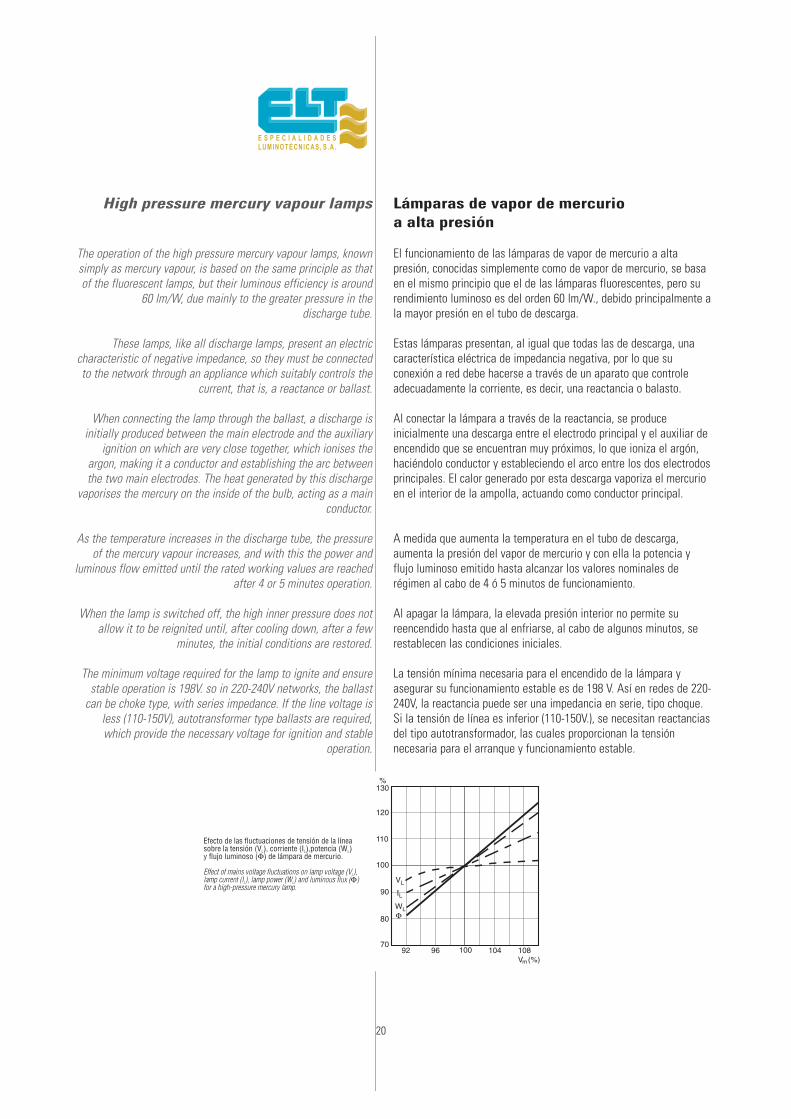
High pressure mercury vapour lamps
The operation of the high pressure mercury vapour lamps, knownsimply as mercury vapour, is based on the same principle as thatof the fluorescent lamps, but their luminous efficiency is around
60 lm/W, due mainly to the greater pressure in the discharge tube.
These lamps, like all discharge lamps, present an electriccharacteristic of negative impedance, so they must be connectedto the network through an appliance which suitably controls the
current, that is, a reactance or ballast.
When connecting the lamp through the ballast, a discharge isinitially produced between the main electrode and the auxiliary
ignition on which are very close together, which ionises theargon, making it a conductor and establishing the arc betweenthe two main electrodes. The heat generated by this discharge
vaporises the mercury on the inside of the bulb, acting as a mainconductor.
As the temperature increases in the discharge tube, the pressureof the mercury vapour increases, and with this the power and
luminous flow emitted until the rated working values are reachedafter 4 or 5 minutes operation.
When the lamp is switched off, the high inner pressure does notallow it to be reignited until, after cooling down, after a few
minutes, the initial conditions are restored.
The minimum voltage required for the lamp to ignite and ensurestable operation is 198V. so in 220-240V networks, the ballast
can be choke type, with series impedance. If the line voltage isless (110-150V), autotransformer type ballasts are required,which provide the necessary voltage for ignition and stable
operation.
Lámparas de vapor de mercurioa alta presión
El funcionamiento de las lámparas de vapor de mercurio a altapresión, conocidas simplemente como de vapor de mercurio, se basaen el mismo principio que el de las lámparas fluorescentes, pero surendimiento luminoso es del orden 60 lm/W., debido principalmente ala mayor presión en el tubo de descarga.
Estas lámparas presentan, al igual que todas las de descarga, unacaracterística eléctrica de impedancia negativa, por lo que suconexión a red debe hacerse a través de un aparato que controleadecuadamente la corriente, es decir, una reactancia o balasto.
Al conectar la lámpara a través de la reactancia, se produceinicialmente una descarga entre el electrodo principal y el auxiliar deencendido que se encuentran muy próximos, lo que ioniza el argón,haciéndolo conductor y estableciendo el arco entre los dos electrodosprincipales. El calor generado por esta descarga vaporiza el mercurioen el interior de la ampolla, actuando como conductor principal.
A medida que aumenta la temperatura en el tubo de descarga,aumenta la presión del vapor de mercurio y con ella la potencia yflujo luminoso emitido hasta alcanzar los valores nominales derégimen al cabo de 4 ó 5 minutos de funcionamiento.
Al apagar la lámpara, la elevada presión interior no permite sureencendido hasta que al enfriarse, al cabo de algunos minutos, serestablecen las condiciones iniciales.
La tensión mínima necesaria para el encendido de la lámpara yasegurar su funcionamiento estable es de 198 V. Así en redes de 220-240V, la reactancia puede ser una impedancia en serie, tipo choque.Si la tensión de línea es inferior (110-150V.), se necesitan reactanciasdel tipo autotransformador, las cuales proporcionan la tensiónnecesaria para el arranque y funcionamiento estable.
130
120
110
100
90
VL
WLΦ
IL
80
7092
Φ
Φ
96 100 104 108Vm(%)
%
Código
Code
LámparaLamp
PotenciaPower
W
CorrienteCurrent
A
∆t
°K
λ PesoWeight
Kg
A B L1 L2 Circuitdiagr. n.º
Esquemaconexión n.º Formato
Format
Homologac.
Approvals
DimensionesDimensions
(mm)
21
EN-61347 y EN-60923 -
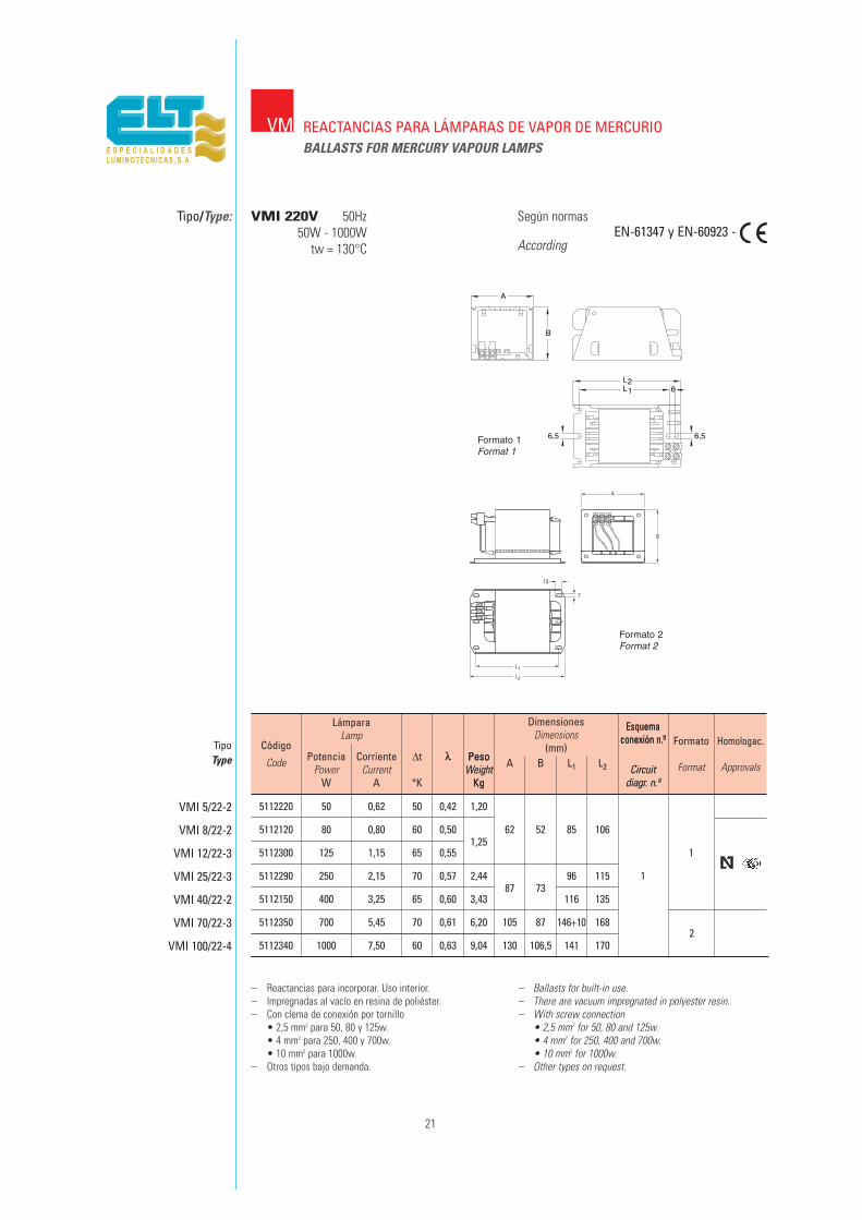
– Reactancias para incorporar. Uso interior.– Impregnadas al vacío en resina de poliéster.– Con clema de conexión por tornillo
• 2,5 mm2 para 50, 80 y 125w.• 4 mm2 para 250, 400 y 700w.• 10 mm2 para 1000w.
– Otros tipos bajo demanda.
– Ballasts for built-in use.– There are vacuum impregnated in polyester resin.– With screw connection
• 2,5 mm2 for 50, 80 and 125w.• 4 mm2 for 250, 400 and 700w.• 10 mm2 for 1000w.
– Other types on request.
VMI 5/22-2
VMI 8/22-2
VMI 12/22-3
VMI 25/22-3
VMI 40/22-2
VMI 70/22-3
VMI 100/22-4
λ PesoWeight
KgCircuit
diagr. n.º
Esquemaconexión n.º
5112220 50 0,62 50 0,42 1,20
5112120 80 0,80 60 0,501,25
62 52 85 106
5112300 125 1,15 65 0,55 1
5112290 250 2,15 70 0,57 2,4487 73
96 115 1
5112150 400 3,25 65 0,60 3,43 116 135
5112350 700 5,45 70 0,61 6,20 105 87 146+10 168
5112340 1000 7,50 60 0,63 9,04 130 106,5 141 1702
VM
Tipo/Type:
REACTANCIAS PARA LÁMPARAS DE VAPOR DE MERCURIOVMBALLASTS FOR MERCURY VAPOUR LAMPS
VMI 220V 50Hz50W - 1000W
tw = 130°C
Formato 1
L2L1
A
B
6
6,5 6,5
Según normas
According
Formato 1Format 1
Formato 2Format 2
TipoType

Código
Code
TipoType
LámparaLamp
PotenciaPower
W
CorrienteCurrent
A
∆t
°K
λ PesoWeight
Kg
A B L1 L2 Circuitdiagr. n.º
Esquemaconexión n.º Formato
Format
Homologac.
Approvals
DimensionesDimensions
(mm)
22
VMI 230V 50Hz50W - 1000W
tw = 130°CEN-61347 y EN-60923 -
– Reactancias para incorporar. Uso interior.– Impregnadas al vacío en resina de poliéster.– Con clema de conexión por tornillo
• 2,5 mm2 para 50, 80 y 125w.• 4 mm2 para 250, 400 y 700w.• 10 mm2 para 1000w.
– Otros tipos bajo demanda.
– Ballasts for built-in use.– There are vacuum impregnated in polyester resin.– With screw connection
• 2,5 mm2 for 50, 80 and 125w.• 4 mm2 for 250, 400 and 700w.• 10 mm2 for 1000w.
– Other types on request.
VMI 5/23-2
VMI 8/23-2
VMI 12/23-3
VMI 25/23-3
VMI 40/23-2
VMI 70/23-3
VHI 100/23-3
λ PesoWeight
KgCircuit
diagr. n.º
Esquemaconexión n.º
5112550 50 0,62 55 0,41 1,20
5112430 80 0,80 60 0,50 1,25 62 52 85 106
5112400 125 1,15 65 0,52 1,25 1
5112410 250 2,15 70 0,55 2,4487 73
96 115 1
5112420 400 3,25 70 0,57 3,43 116 135
5112570 700 5,45 70 0,61 6,20 105 87 146+10 168
6112262 1000 7,50 65 0,60 9,20 130 106,5 141 1702
Formato 1
L2L1
A
B
6
6,5 6,5Formato 1Format 1
Formato 2Format 2
Según normas
According
VM REACTANCIAS PARA LÁMPARAS DE VAPOR DE MERCURIOBALLASTS FOR MERCURY VAPOUR LAMPS
Tipo/Type:
Código
Code
TipoType
LámparaLamp
PotenciaPower
W
CorrienteCurrent
A
∆t
°K
λ PesoWeight
Kg
A B L1 L2 Circuitdiagr. n.º
Esquemaconexión n.º Formato
Format
Homologac.
Approvals
DimensionesDimensions
(mm)
23
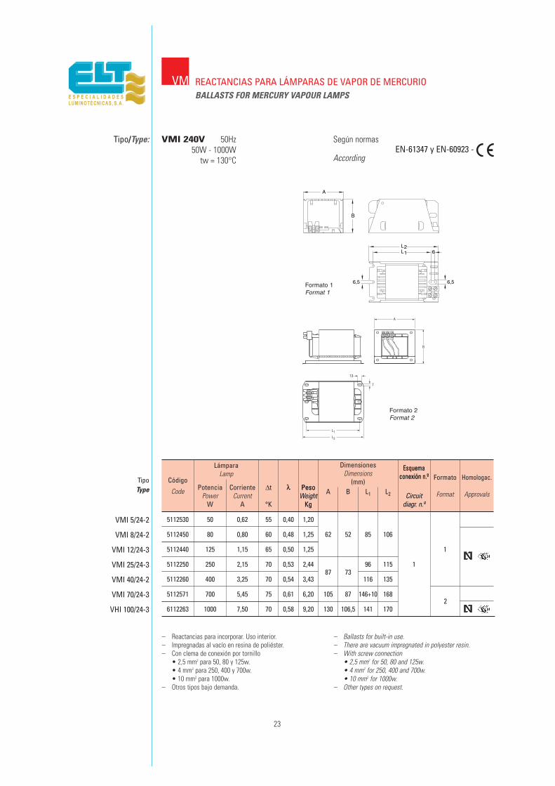
VMI 240V 50Hz50W - 1000W
tw = 130°CEN-61347 y EN-60923 -
– Reactancias para incorporar. Uso interior.– Impregnadas al vacío en resina de poliéster.– Con clema de conexión por tornillo
• 2,5 mm2 para 50, 80 y 125w.• 4 mm2 para 250, 400 y 700w.• 10 mm2 para 1000w.
– Otros tipos bajo demanda.
– Ballasts for built-in use.– There are vacuum impregnated in polyester resin.– With screw connection
• 2,5 mm2 for 50, 80 and 125w.• 4 mm2 for 250, 400 and 700w.• 10 mm2 for 1000w.
– Other types on request.
VMI 5/24-2
VMI 8/24-2
VMI 12/24-3
VMI 25/24-3
VMI 40/24-2
VMI 70/24-3
VHI 100/24-3
λ PesoWeight
KgCircuit
diagr. n.º
Esquemaconexión n.º
5112530 50 0,62 55 0,40 1,20
5112450 80 0,80 60 0,48 1,25 62 52 85 106
5112440 125 1,15 65 0,50 1,25 1
5112250 250 2,15 70 0,53 2,4487 73
96 115 1
5112260 400 3,25 70 0,54 3,43 116 135
5112571 700 5,45 75 0,61 6,20 105 87 146+10 168
6112263 1000 7,50 70 0,58 9,20 130 106,5 141 1702
Formato 1
L2L1
A
B
6
6,5 6,5Formato 1Format 1
Formato 2Format 2
VM REACTANCIAS PARA LÁMPARAS DE VAPOR DE MERCURIOBALLASTS FOR MERCURY VAPOUR LAMPS
Tipo/Type: Según normas
According
Código
Code
TipoType
LámparaLamp
PotenciaPower
W
CorrienteCurrent
A
∆t
°K
λ PesoWeight
Kg
A B L1 L2 Circuitdiagr. n.º
Esquemaconexión n.º Formato
Format
DimensionesDimensions
(mm)
24
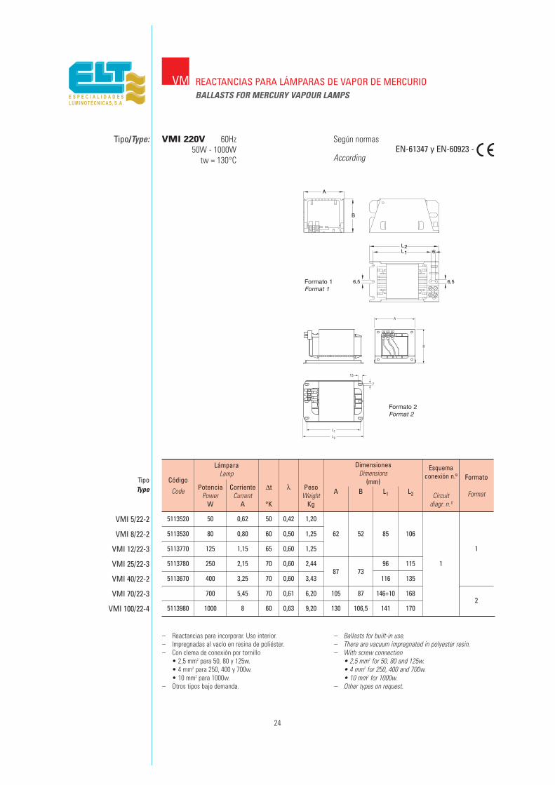
VMI 220V 60Hz50W - 1000W
tw = 130°CEN-61347 y EN-60923 -
– Reactancias para incorporar. Uso interior.– Impregnadas al vacío en resina de poliéster.– Con clema de conexión por tornillo
• 2,5 mm2 para 50, 80 y 125w.• 4 mm2 para 250, 400 y 700w.• 10 mm2 para 1000w.
– Otros tipos bajo demanda.
– Ballasts for built-in use.– There are vacuum impregnated in polyester resin.– With screw connection
• 2,5 mm2 for 50, 80 and 125w.• 4 mm2 for 250, 400 and 700w.• 10 mm2 for 1000w.
– Other types on request.
VMI 5/22-2
VMI 8/22-2
VMI 12/22-3
VMI 25/22-3
VMI 40/22-2
VMI 70/22-3
VMI 100/22-4
5113520 50 0,62 50 0,42 1,20
5113530 80 0,80 60 0,50 1,25 62 52 85 106
5113770 125 1,15 65 0,60 1,25 1
5113780 250 2,15 70 0,60 2,4487 73
96 115 1
5113670 400 3,25 70 0,60 3,43 116 135
700 5,45 70 0,61 6,20 105 87 146+10 168
5113980 1000 8 60 0,63 9,20 130 106,5 141 1702
Formato 1
L2L1
A
B
6
6,5 6,5Formato 1Format 1
Formato 2Format 2
VM REACTANCIAS PARA LÁMPARAS DE VAPOR DE MERCURIOBALLASTS FOR MERCURY VAPOUR LAMPS
Tipo/Type: Según normas
According
50 0,62 55 0,29
5612540 80 0,80 60 0,43 1,48 62 120 69 85 106
5612550 125 1,15 65 0,65 0,90 7
5612560 250 2,15 70 1,27 2,8087 145 91
96 115
5612570 400 3,25 70 2,00 4,00 116 135
50 0,62 50 0,30
5612500 80 0,80 60 0,44 1,48 62 120 69 85 106
5612510 125 1,15 65 0,66 0,90 7
5612520 250 2,15 70 1,30 2,8087 145 91
96 115
5612530 400 3,25 65 2,00 4,00 116 135
25
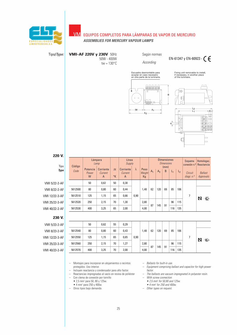
EQUIPOS COMPLETOS PARA LÁMPARAS DE VAPOR DE MERCURIOASSEMBLIES FOR MERCURY VAPOUR LAMPS
Tipo/Type: VMI-AF 220V y 230V 50Hz50W - 400W
tw = 130°C
Según normas
AccordingEN-61347 y EN-60923 -
L2
A2
A1 L1
6
658
B
– Montajes para incorporar en alojamientos o recintosprotegidos. Uso interior.
– Incluyen reactancia y condensador para alto factor.– Reactancias impregnadas al vacío en resina de poliéster– Con clema de conexión por tornillo
• 2,5 mm2 para 50, 80 y 125w.• 4 mm2 para 250 y 400w.
– Otros tipos bajo demanda.
– Ballasts for built-in use.– Equipment comprising ballast and capacitor for high power
factor.– The ballasts are vacuum impregnated in polyester resin.– With screw connection
• 2,5 mm2 for 50,80 and 125w.• 4 mm2 for 250 and 400w.
– Other types on request.
TipoType
220 V.
VMI 5/22-2-AF
VMI 8/22-2-AF
VMI 12/22-3-AF
VMI 25/22-3-AF
VMI 40/22-2-AF
LámparaLamp
PotenciaPower
W
CorrienteCurrent
A
∆t
°K
CorrienteCurrent
A
LíneaSupply
λ PesoWeight
Kg
A1 A2 B L1 L2 Circuitdiagr. n.º
Esquemaconexión n.º
BallastApprovals
Homologac.Reactancia
DimensionesDimensions
(mm)Código
Code
230 V.
VMI 5/23-2-AF
VMI 8/23-2-AF
VMI 12/23-3-AF
VMI 25/23-3-AF
VMI 40/23-2-AF
Escuadra desmontable paraacoplar en caso necesarioen otra parte de la luminaria.
Fixing unit removable to install,if necessary, in another placeof the luminaire.
VM
5110320 50 0,62 55 0,42
5110330 80 0,80 60 0,51 1,39 69 60,3 120 132 1
5110340 125 1,15 75 0,55
5110370 250 2,15 70 0,57 2,60 95 110 12
5110380 400 3,25 70 0,60 3,7092 83
115 130
5110080 700 5,45 60 0,62 8,40 252 2753
5110090 1000 7,50 80 0,64 10,00 302 325
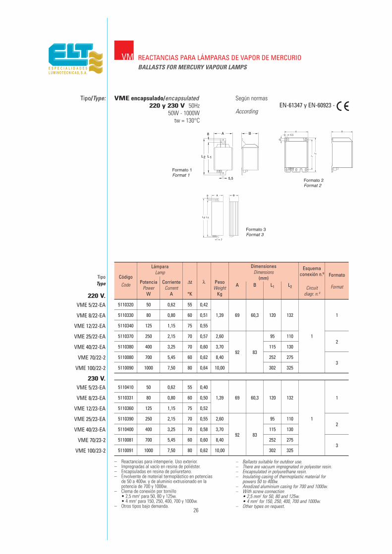
26
VME encapsulado/encapsulated220 y 230 V 50Hz
50W - 1000Wtw = 130°C
EN-61347 y EN-60923 -
8
L2
5,5
L1
BA
L2
7
L1
A9 B
– Reactancias para intemperie. Uso exterior.– Impregnadas al vacío en resina de poliéster.– Encapsuladas en resina de poliuretano.– Envolvente de material termoplástico en potencias
de 50 a 400w. y de aluminio extrusionado en lapotencia de 700 y 1000w.
– Clema de conexión por tornillo• 2,5 mm2 para 50, 80 y 125w.• 4 mm2 para 150, 250, 400, 700 y 1000w.
– Otros tipos bajo demanda.
– Ballasts suitable for outdoor use.– There are vacuum impregnated in polyester resin.– Encapsulated in polyurethane resin.– Insulating casing of thermoplastic material for
powers 50 to 400w.– Anodized aluminium casing for 700 and 1000w.– With screw connection
• 2,5 mm2 for 50, 80 and 125w.• 4 mm2 for 150, 250, 400, 700 and 1000w.
– Other types on request.
Código
Code
TipoType
VME 5/22-EA
VME 8/22-EA
VME 12/22-EA
VME 25/22-EA
VME 40/22-EA
VME 70/22-2
VME 100/22-2
5110410 50 0,62 55 0,40
5110331 80 0,80 60 0,50 1,39 69 60,3 120 132 1
5110360 125 1,15 75 0,52
5110390 250 2,15 70 0,55 2,60 95 110 12
5110400 400 3,25 70 0,58 3,7092 83
115 130
5110081 700 5,45 60 0,60 8,40 252 2753
5110091 1000 7,50 80 0,62 10,00 302 325
VME 5/23-EA
VME 8/23-EA
VME 12/23-EA
VME 25/23-EA
VME 40/23-EA
VME 70/23-2
VME 100/23-2
LámparaLamp
PotenciaPower
W
CorrienteCurrent
A
∆t
°K
λ PesoWeight
Kg
A B L1 L2 Circuitdiagr. n.º
Esquemaconexión n.º Formato
Format
DimensionesDimensions
(mm)
220 V.
230 V.
Formato 1Format 1
Formato 3Format 3
Formato 2Format 2
VM REACTANCIAS PARA LÁMPARAS DE VAPOR DE MERCURIOBALLASTS FOR MERCURY VAPOUR LAMPS
Tipo/Type: Según normas
According
27
REACTANCIAS PARA LÁMPARAS DE VAPORDE SODIO A ALTA PRESIÓN
BALLASTS FOR HIGH PRESSURESODIUM VAPOUR LAMPS
VS
28
High pressure sodium vapour lamps
These lamps are made up of an aluminium oxide discharge tube ableto resist temperatures of 1000°C and the chemical action of the
sodium vapour at those temperatures, which permits thetransmission of 90% the visible light produced by the electricdischarge on the inside. It is closed with synthetic corundum
stoppers, where the electrodes are supported. There is sodium andmercury amalgam in xenon atmosphere at high pressure
on the inside
The discharge tube is housed on the inside of a hard glass bulb,resistant to the inclemency, which acts as protection and electric and
thermal insulation.
Like all discharge lamps they require a ballast which limits thecurrent to the desired values and due to the high pressure of the
gases on the inside of the discharge tube, they require much highervoltages than that of the network for ignition, around 2 to 5 KV.,
depending on the type of lamp. Voltages which are provided by thestarters either on their own or combined with the ballast.
In contrast to other discharge lamps, they have a positivecharacteristics current intensity –arc voltage: that is, with increasesin the lamp current, the voltage in the discharge tube increases withthe subsequent increase in power and vice-versa, with decreases in
the lamp current, the voltage in the discharge tube decreases, aswell as the power absorbed by the lamp.
They also have a peculiarity which is different to the rest of thedischarge lamps, and that is that, with the accumulation of operating
hours, the arc voltage in the discharge tube increases above itsinitial value, until it reaches such a magnitude that the
instantaneous value of the reignition voltage approaches theinstantaneous value of the network, time when the stability of the
arc is not possible and the lamp goes out.
Operation
These lamps must work within some power and arc voltage limitswhich configure a paralelogram like the one which appears in thediagram, specific for each lamp according to EN-60662 = CEI 662.
So that a ballast can comply with the requirements of the H.P.sodium vapour lamps its characteristic curve must pass as near as
possible to the optimum operation point (rated power - rated arcvoltage) and it must also cut the maximum and minimum voltage
lines at points between the maximum and minimum power limits,between which the characteristic curve must remain throughout
the whole variation experienced by the voltage of the lamp duringits working life.
Lámparas de vapor de sodio a alta presión
Estas lámparas están constituidas por un tubo de descarga de óxidode aluminio capaz de resistir temperaturas de 1000°C y la acciónquímica del vapor de sodio a esas temperaturas y que permitetransmitir el 90% de la luz visible producida por la descarga eléctricaen su interior. Está cerrado mediante tapones de corindón sintético,en los que se soportan los electrodos. En su interior se encuentra unaamalgama de sodio y mercurio en atmósfera de xenon a elevadapresión.
El tubo de descarga se aloja en el interior de una ampolla de vidrioduro, resistente a la intemperie, que le sirve de protección yaislamiento eléctrico y térmico.
Como todas las lámparas de descarga necesitan una reactancia quelimite la corriente a los valores deseados y debido a la elevadapresión de los gases en el interior del tubo de descarga, requierentensiones para el encendido muy superiores a la de la red, del ordende 2 a 5 KV., dependiendo del tipo de lámpara. Tensiones que sonproporcionadas por los arrancadores bien por sí solos o encombinación con la reactancia.
Como contraste con las otras lámparas de descarga, tienen unacaracterística intensidad de corriente - tensión de arco, positiva; esdecir, a aumentos de corriente en lámpara, la tensión en el tubo dedescarga aumenta con el consiguiente aumento de potencia yviceversa, a disminuciones de la corriente en la lámpara, la tensión enel tubo de descarga disminuye, así como la potencia absorbida por lalámpara.
También presentan otra particularidad distinta al resto de laslámparas de descarga, y es que, con la acumulación de horas defuncionamiento, la tensión de arco en el tubo de descarga vaincrementándose sobre su valor inicial, hasta que llega a unamagnitud tal, que el valor instantáneo de la tensión de reencendidose aproxima al valor instantáneo de la red, momento en que laestabilidad del arco no es posible y la lámpara se apaga.
Funcionamiento
Estas lámparas deben trabajar dentro de unos límites de potenciay tensión de arco que configuran un paralelogramo como el queaparece en la figura, específico para cada lámpara según normaEN-60662 = CEI 662.
Para que una reactancia cumpla con los requisitos de las lámparas devapor de sodio A.P., es necesario que su curva característica pase lomás cerca posible del punto óptimo de funcionamiento (potencianominal - tensión de arco nominal) y que, además, corte a las líneasde tensión máxima y mínima en puntos comprendidos entre los límitesde potencia máxima y mínima, entre las que debe permanecer lacurva característica a lo largo de toda la variación que experimenta elvoltaje de la lámpara durante su vida útil.

29
Ballasts
For line voltages of 220-240V., the necessary ballast need only bechoke type or series impedance. If the line voltage is 100 ÷ 150 V., or
380 ÷ 400V., the ballast must be autotransformer.
The life of these lamps is affected a great deal by variations in theline voltage, so this must not differ more than ± 5% the rated
voltage of the ballast.
Ballasts are manufactured for two or more voltages in order to, thus,use the most advisable in the installation. If long-lasting or
permanent variations in the line voltage of over 5% are foreseen,self-regulating ballasts must be installed if we wish to obtain a
suitable lifespan of the lamps.
Reactancias
Para tensiones de línea de 220-240V., la reactancia necesaria bastarácon que sea de impedancia en serie o de choque. Si la tensión delínea es de 100 ÷ 150 V., ó 380 ÷ 400V., la reactancia deberá ser deltipo autotransformadora.
La vida de estas lámparas se ve muy afectada por las variaciones dela tensión de línea, por lo que ésta no debe diferir más del ±5% de latensión nominal de la reactancia.
Se fabrican reactancias para dos o más tensiones y así utilizar laque más convenga en la instalación. Si se prevé que habrávariaciones de tensión de línea mayores del 5%, de larga duracióno permanente, se deben instalar reactancias del tipo autorreguladorasi queremos obtener una duración adecuada de las lámparas.
130
120
110
100
90
VL
WL
Φ
IL
80
70
Φ
Φ
92 96 100 104 108Vm(%)
%
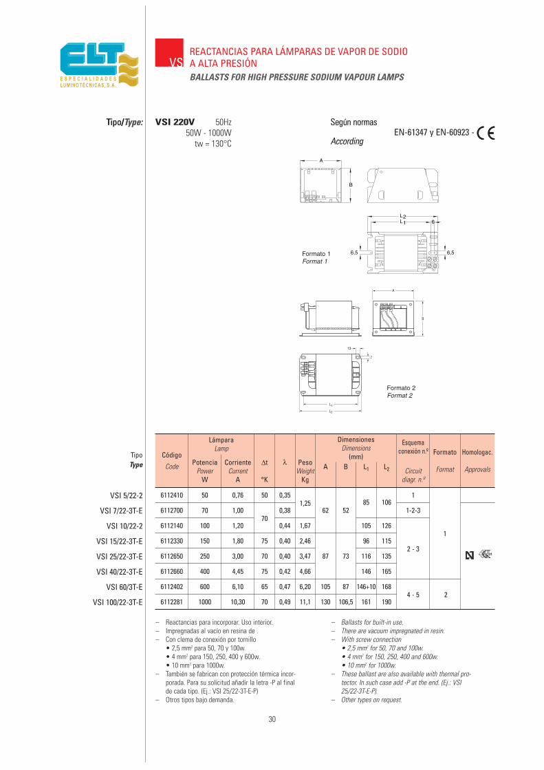
6112410 50 0,76 50 0,351,25
1
6112700 70 1,00 0,38 62 5285 106
1-2-3
6112140 100 1,2070
0,44 1,67 105 1261
6112330 150 1,80 75 0,40 2,46 96 1152 - 3
6112650 250 3,00 70 0,40 3,47 87 73 116 135
6112660 400 4,45 75 0,42 4,66 146 165
6112402 600 6,10 65 0,47 6,20 105 87 146+10 1684 - 5 2
6112281 1000 10,30 70 0,49 11,1 130 106,5 161 190
30
VM
Tipo/Type: Según normas
AccordingEN-61347 y EN-60923 -
– Reactancias para incorporar. Uso interior.– Impregnadas al vacío en resina de .– Con clema de conexión por tornillo
• 2,5 mm2 para 50, 70 y 100w.• 4 mm2 para 150, 250, 400 y 600w.• 10 mm2 para 1000w.
– También se fabrican con protección térmica incor-porada. Para su solicitud añadir la letra -P al finalde cada tipo. (Ej.: VSI 25/22-3T-E-P)
– Otros tipos bajo demanda.
– Ballasts for built-in use.– There are vacuum impregnated in resin.– With screw connection
• 2,5 mm2 for 50, 70 and 100w.• 4 mm2 for 150, 250, 400 and 600w.• 10 mm2 for 1000w.
– These ballast are also available with thermal pro-tector. In such case add -P at the end. (Ej.: VSI25/22-3T-E-P).
– Other types on request.
Código
Code
TipoType
VSI 5/22-2
VSI 7/22-3T-E
VSI 10/22-2
VSI 15/22-3T-E
VSI 25/22-3T-E
VSI 40/22-3T-E
VSI 60/3T-E
VSI 100/22-3T-E
LámparaLamp
PotenciaPower
W
CorrienteCurrent
A
∆t
°K
λ PesoWeight
Kg
A B L1 L2 Circuitdiagr. n.º
Esquemaconexión n.º Formato
Format
Homologac.
Approvals
DimensionesDimensions
(mm)
01
VSREACTANCIAS PARA LÁMPARAS DE VAPOR DE SODIOA ALTA PRESIÓNBALLASTS FOR HIGH PRESSURE SODIUM VAPOUR LAMPS
Tipo/Type: VSI 220V 50Hz50W - 1000W
tw = 130°C
Según normas
According
Formato 1
L2L1
A
B
6
6,5 6,5Formato 1Format 1
Formato 2Format 2

6112420 50 0,76 55 0,341,25
1
6112040 70 1,00 0,37 62 5285 106
1-2-3
6112180 100 1,2070
0,42 1,67 105 126
6112340 150 1,80 75 0,40 2,46 96 115 1
6112350 250 3,00 75 0,40 3,4787 73
116 135 2 - 3
6112360 400 4,45 80 0,42 4,66146 165
6112361 400 4,60 70 0,42 4,77
6112401 600 6,10 70 0,45 6,20 105 87 146+10 1684 - 5 2
6112282 1000 10,30 75 0,47 11,10 130 106,5 161 190
31
Tipo/Type: VSI 230V 50Hz50W - 1000W
tw = 130°C
Según normas
AccordingEN-61347 y EN-60923 -
01
– Reactancias para incorporar. Uso interior.– Impregnadas al vacío en resina de poliéster.– Con clema de conexión por tornillo
• 2,5 mm2 para 50, 70 y 100w.• 4 mm2 para 150, 250, 400 y 600w.• 10 mm2 para 1000w.
– También se fabrican con protección térmica incor-porada. Para su solicitud añadir la letra -P al finalde cada tipo. (Ej.: VSI 25/22-3T-D-P)
– Otros tipos bajo demanda.
– Ballasts for built-in use.– There are vacuum impregnated in polyester resin.– With screw connection
• 2,5 mm2 for 50, 70 and 100w.• 4 mm2 for 150, 250, 400 and 600w.• 10 mm2 for 1000w.
– These ballast are also available with thermal pro-tector. In such case add -P at the end. (Ej.: VSI25/22-3T-D-P).
– Other types on request.
Código
Code
TipoType
VSI 5/23-2
VSI 7/22-3T-D
VSI 10/22-3T-B
VSI 15/22-3T-D
VSI 25/22-3T-D
VSI 40/22-3T-D
VSI 40/23-3T-D
VSI 60/3T-D
VSI 100/22-3T-D
LámparaLamp
PotenciaPower
W
CorrienteCurrent
A
∆t
°K
λ PesoWeight
Kg
A B L1 L2Circuit
diagr. n.º
Esquemaconexión n.º Formato
Format
Homologac.
Approvals
DimensionesDimensions
(mm)
WSVSREACTANCIAS PARA LÁMPARAS DE VAPOR DE SODIOA ALTA PRESIÓNBALLASTS FOR HIGH PRESSURE SODIUM VAPOUR LAMPS
Formato 1
L2L1
A
B
6
6,5 6,5Formato 1Format 1
Formato 2Format 2

6112890 50 0,76 60 0,351,25
1
6111510 70 1,00 0,36 62 5285 106
1 - 2 - 3
6111520 100 1,2070
0,40 1,67 105 1261
6111530 150 1,80 75 0,40 2,46 96 115
6111540 250 3,00 75 0,40 3,47 87 73 116 1352 - 3
6111550 400 4,45 80 0,42 4,66 146 165
6112403 600 6,10 70 0,44 6,20 105 87 146+10 1684 - 5 2
6112283 1000 10,30 80 0,45 11,10 130 106,5 161 190
32
VSI 240V 50Hz50W - 1000W
tw = 130°CEN-61347 y EN-60923 -
– Reactancias para incorporar. Uso interior.– Impregnadas al vacío en resina de poliéster.– Con clema de conexión por tornillo
• 2,5 mm2 para 50, 70 y 100w.• 4 mm2 para 150, 250, 400 y 600w.• 10 mm2 para 1000w.
– También se fabrican con protección térmica incor-porada. Para su solicitud añadir la letra -P al finalde cada tipo. (Ej.: VSI 25/22-3T-G-P)
– Otros tipos bajo demanda.
– Ballasts for built-in use.– There are vacuum impregnated in polyester resin.– With screw connection
• 2,5 mm2 for 50, 70 and 100w.• 4 mm2 for 150, 250, 400 and 600w.• 10 mm2 for 1000w.
– These ballast are also available with thermal pro-tector. In such case add -P at the end. (Ej.: VSI25/22-3T-G-P).
– Other types on request.
Código
Code
TipoType
VSI 5/24-2
VSI 7/22-3T-G
VSI 10/22-3T-G
VSI 15/22-3T-G
VSI 25/22-3T-G
VSI 40/22-3T-G
VSI 60/3T-G
VSI 100/22-3T-G
LámparaLamp
PotenciaPower
W
CorrienteCurrent
A
∆t
°K
λ PesoWeight
Kg
A B L1 L2 Circuitdiagr. n.º
Esquemaconexión n.º Formato
Format
Homologac.
Approvals
DimensionesDimensions
(mm)
WSVSREACTANCIAS PARA LÁMPARAS DE VAPOR DE SODIOA ALTA PRESIÓNBALLASTS FOR HIGH PRESSURE SODIUM VAPOUR LAMPS
01
Formato 1
L2L1
A
B
6
6,5 6,5Formato 1Format 1
Formato 2Format 2
Tipo/Type: Según normas
According

6113870 50 0,76 60 0,351,25
1
6113920 70 1,00 65 0,38 62 5285 106
1-2-3
6113860 100 1,20 0,44 1,67 105 1261
6113590 150 1,8070
0,42 2,46 96 1152 - 3
6113601 250 3,00 0,42 3,47 87 73 116 135
6113610 400 4,45 0,45 4,66 146 165
600 6,10 70 0,47 6,20 105 87 146+10 1684 - 5 2
6113882 1000 10,30 70 0,49 11,10 130 106,5 161 190
33
VSI 220V 60Hz50W - 1000W
tw = 130°CEN-61347 y EN-60923 -
– Reactancias para incorporar. Uso interior.– Impregnadas al vacío en resina de poliéster.– Clema de conexión por tornillo
• 2,5 mm2 para 50, 70 y 100w.• 4 mm2 para 150, 250, 400 y 600w.• 10 mm2 para1000w.
– También se fabrican con protección térmica incor-porada. Para su solicitud añadir la letra -P al finalde cada tipo. (Ej.: VSI 25/22-3T-E6-P)
– Otros tipos bajo demanda.
– Ballasts for built-in use.– There are vacuum impregnated in polyester resin.– With screw connection
• 2,5 mm2 for 50, 70 and 100w.• 4 mm2 for 150, 250, 400 and 600w.• 10 mm2 for 1000w.
– These ballast are also available with thermal pro-tector. In such case add -P at the end. (Ej.: VSI25/22-3T-E6-P).
– Other types on request.
Código
Code
TipoType
VSI 5/22-2
VSI 7/22-3T-E6
VSI 10/22-2
VSI 15/22-3T-E6
VSI 25/22-3T-E6
VSI 40/22-3T-E6
VSI 60/3T-E6
VSI 100/22-3T-E6
LámparaLamp
PotenciaPower
W
CorrienteCurrent
A
∆t
°K
λ PesoWeight
Kg
A B L1 L2 Circuitdiagr. n.º
Esquemaconexión n.º Formato
Format
DimensionesDimensions
(mm)
WSVSREACTANCIAS PARA LÁMPARAS DE VAPOR DE SODIOA ALTA PRESIÓNBALLASTS FOR HIGH PRESSURE SODIUM VAPOUR LAMPS
Formato 1
L2L1
A
B
6
6,5 6,5Formato 1Format 1
Formato 2Format 2
Tipo/Type: Según normas
According
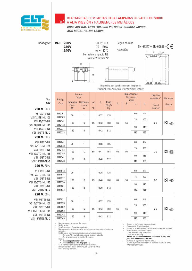
34
VSREACTANCIAS COMPACTAS PARA LÁMPARAS DE VAPOR DE SODIOA ALTA PRESIÓN Y HALOGENUROS METÁLICOSCOMPACT BALLASTS FOR HIGH PRESSURE SODIUM VAPOURAND METAL HALIDE LAMPS
Tipo/Type: VSI 220V 50Hz/60Hz230V 70 - 150W240V tw = 130°C
Formato compacto NLCompact format NL
Según normas
According
Disponible con tapa base de dos longitudesAvailable with base plate of two different lengths
EN-61347 y EN-60923 - -
– Reactancias para incorporar. Uso interior.– Núcleo al aire.– Tamaño compacto. Dimensiones reducidas.– Reactancias para alojar en espacios reducidos, proyectores, cajas y luminarias
pequeñas.– Posibilidad de suministro con dos tamaños de base de anclaje:
• Una corta. Muy ajustada para anclarla, pero muy reducida.• Una larga. Con mayor comodidad de fijación.
– Bornes:• Conexión por tornillo 4 mm2.• Conexión rápida 1-1,5 (bajo pedido)
– Se pueden fabricar reactancias con Protección Térmica.Para solicitar debe añadir la letra P (Ejem. VSI15/3TD-P-NL).
– Otros tipos bajo demanda.
– Ballasts for built-in use. Indoor application.– Compact size. Small dimensions.– Suitable to be used where a low cross-section ballast is required.– Available with two different lengths.
Short: Reduced fixing dimensions.Large: For easier fixing.
– Ballast are equiped with screw connection (4 mm2). Andpush wire connection (1-1,5 mm2).
– Available on request with thermal cut-out.To order it you must include the “P” (Example: VSI15/3TD-P-NL).
– Other types on request.
611270170 1 0,37 1,35
60 856112703
75 1006112141
100 1,2 65 0,43 1,68 66 56 2-36112143
90 1156112331
150 1,8 0,42 2,126112333 110 135
Código
Code
TipoType
VSI 7/3TE-NLVSI 7/3TE-NL-100
VSI 10/3TE-NLVSI 10/3TE-NL-115
VSI 15/3TE-NLVSI 15/3TE-NL-2
LámparaLamp
PotenciaPower
W
CorrienteCurrent
A
∆t
°K
λ PesoWeight
Kg
A B L1 L2 Circuitdiagr. n.º
Esquemaconexión n.º Formato
Format
DimensionesDimensions
(mm)
220 V. 50Hz
01
611204170 1 0,36 1,35
60 856112043
75 1006112183
100 1,2 65 0,41 1,68 66 56 2-36112185
90 1156112341
150 1,8 0,40 2,126112343 110 135
VSI 7/3TD-NLVSI 7/3TD-NL-100
VSI 10/3TD-NLVSI 10/3TD-NL-115
VSI 15/3TD-NLVSI 15/3TD-NL-2
230 V. 50Hz
01
611151270 1 0,35 1,35
60 856111514
75 1006111522
100 1,2 65 0,40 1,68 66 56 2-36111524
90 1156111531
150 1,8 0,39 2,126111533 110 135
VSI 7/3TG-NLVSI 7/3TG-NL-100
VSI 10/3TG-NLVSI 10/3TG-NL-115
VSI 15/3TG-NLVSI 15/3TG-NL-2
240 V. 50Hz
01
611392170 1 0,37 1,35
60 856113923
75 1006113862
100 1,2 65 0,43 1,68 66 56 2-36113863
90 1156113742
150 1,8 0,42 2,126113745 110 135
VSI 7/3TE6-NLVSI 7/3TE6-NL-100
VSI 10/3TE6-NLVSI 10/3TE6-NL-115
VSI 15/3TE6-NLVSI 15/3TE6-NL-2
220 V. 60Hz
01

2 50 0,76 0,28 50 1,47
6212460 70 0,98 0,4070
1,55 62 111 7285 106
6212060 1 100 1,20 0,55 0,90 1,90 105 12620
6212470 150 1,80 0,81+
75 2,75 96 115
62124802
250 3,00 1,380,05
70 3,70 87 145 91 116 1357
6212490 400 4,45 2,10 75 5,00 146 165
35
VSEQUIPOS COMPLETOS PARA LÁMPARAS DE VAPOR DE SODIOA ALTA PRESIÓNASSEMBLIES FOR HIGH PRESSURE SODIUM VAPOUR LAMPS
Tipo/Type: VSI-AF 220V y 230V 50Hz50W - 400W
tw = 130°C
Según normas
AccordingEN-61347 y EN-60923 -
– Montajes para incorporar en alojamientos o recintos prote-gidos. Uso interior.
– Incluyen reactancia, condensador y arrancador de tipotransformación.
– También se fabrican con arrancador de tipo independiente.– También se fabrican con protección térmica incorporada.– Reactancias impregnadas al vacío en resina de políester.– Con clema de conexión por tornillo
• 2,5 mm2 para 50, 70 y 100w.• 4 mm2 para 150, 250 y 400w.
– Otros tipos bajo demanda.
– Ballasts for built-in use.– Equipment comprising ballast, capacitor
and pulse-transformer.– Also available with superimposed ignitor.– Also available with thermal protector.– There are vacuum impregnated in polyester resin.– With screw connection
• 2,5 mm2 for 50, 70 and 100w.• 4 mm2 for 150, 250 and 400w.
– Other types on request.
Código
Code
TipoType
220 V.
230 V.
VSI 5/22-2AF
VSI 7/22-3AF-100
VSI 10/22-2AF-100
VSI 15/22-3AF-100
VSI 25/22-3AF-100
VSI 40/22-3AF-100
LámparaLamp
FormatoFormat
PotenciaPower
W
CorrienteCurrent
A
∆t
°K
CorrienteCurrent
A
LíneaSupply
λ PesoWeight
Kg
A1 A2 B L1 L2 Circuitdiagr. n.º
Esquemaconexión n.º
Approvals
Homologac.DimensionesDimensions
(mm)
VSI 5/23-2AF
VSI 7/23-3AF-100
VSI 10/23-2AF-100
VSI 15/23-2AF-100
VSI 25/23-3AF-100
VSI 40/23-3AF-100
01
(componentes)(components)
2 50 0,76 0,28 50 1,47
6212610 70 0,98 0,40 1,55 62 111 7285 106
6212210 1 100 1,20 0,55 0,9070
1,90 105 12620
6212620 150 1,80 0,78+
2,75 96 115
62122302
250 3,00 1,330,05 75
3,70 87 145 91 116 1357
6212241 400 4,45 2,00 80 5,00 146 165
01
(componentes)(components)
Formato 2Format 2

36
6212704 70 0,98 0,40 1,45 85 158
6212713 100 1,20 0,5570
1,8762 77
105 178
6212730 150 1,80 0,79 2,86 96 175 7
6212780 250 3 1,3375
3,87 87 76 116 195
6212790 400 4,45 2,05 80 5,06 146 225
VSIARCE
EQUIPOS COMPLETOS ENCHUFABLES PARA LÁMPARASDE VAPOR DE SODIO A ALTA PRESIÓNASSEMBLIES FOR HIGH PRESSURE SODIUM VAPOUR LAMPS
Tipo/Type: Según normas
According
EN-61347 y EN-60923EN-60927
– Ballast for built-in use.– Ballast and subset which plugs in are included.
Equipment comprising ignitor, capacitor and termi-nal for the net and lamp.
– The subset is easily separable from the ballast.– Also available with thermal protector.– To demand, please, add the letter -P at the end of
each type. (Ex. VSI 15/23-ARCE-150-P).– It is obligatory to use the central fixing hole
(*) to assure the continuity of the earth termi-nal.
– Quick installation. Only connecting to the net andlamp.
– There are vacuum impregnated in polyester resin.– Connection terminals by screw 2.5 mm.– Other voltages and frequencies on request.
Código
Code
TipoType
VSI 7/23-ARCE-100
VSI 10/23-ARCE-100
VSI 15/23-ARCE-100
VSI 25/23-ARCE-100
VSI 40/23-ARCE-100
LámparaLamp
LíneaSupply
PotenciaPower
W
CorrienteCurrent
A
CorrienteCurrent
A
∆t
°K
λ PesoWeight
Kg
A B L1 L2 Circuitdiagr. n.º
Esquemaconexión
n.º Homol
Approvals
DimensionesDimensions
(mm)
0,90+
0,0501
CON ARRANCADOR DEPENDIENTE / With impulse transformer system230 V.
6212705 70 0,98 0,40 1,50 85 158
6212714 100 1,20 0,55 70 1,9262 77
105 178
6212731 150 1,80 0,79 2,91 96 175 7
6212781 250 3 1,3375
3,92 87 76 116 195
6212791 400 4,45 2,05 80 5,11 146 225
VSI 7/23-ARCE-150
VSI 10/23-ARCE-150
VSI 15/23-ARCE-150
VSI 25/23-ARCE-400
VSI 40/23-ARCE-400
0,90+
0,0501
CON ARRANCADOR INDEPENDIENTE / With superimposed system independent ignitor230 V.
– Equipos para incorporar en alojamientos o recintosprotegidos. Uso interior.
– Incluyen reactancia y subconjunto enchufable queincorpora arrancador, condensador y bornas parared y lámpara.
– El subconjunto es fácilmente separable de la reac-tancia.
– También se fabrican con protección térmica incor-porada. Para su solicitud añadir la letra -P al finalde cada tipo. (ej. VSI 15/23-ARCE-150-P).
– Es obligatorio utilizar el anclaje central (*)para asegurar la continuidad de la toma detierra.
– Gran rapidez de instalación. Sólo conectar red ylámpara.
– Reactancias impregnadas al vacío en resina depoliéster.
– Clemas de conexión por tornillo de 2,5 mm2.– Otras tensiones y frecuencias bajo demanda.
VSI-ARCE 230V 50Hz70 - 400W
tw = 130°C
70 y 100W 150 - 250 y 400W

37
6110190 50 0,76 60 0,35 1,39 1
6110330 70 1,00 0,38 1,52 69 60,3112 132 1
6110170 100 1,20 0,44 1,90 106 118
6110360 150 1,80 70 0,40 2,60 95 111 2 - 3
6110350 250 3,00 0,40 3,70 92 83 115 1312
6110370 400 4,45 0,42 5,00 145 161
VSREACTANCIAS PARA LÁMPARAS DE VAPOR DE SODIOA ALTA PRESIÓNBALLASTS FOR HIGH PRESSURE SODIUM VAPOUR LAMPS
Tipo/Type: VSE encapsulado/encapsulated220 y 230V 50Hz
50W - 400Wtw = 130°C
Según normas
AccordingEN-61347 y EN-60923 -
8
L2
5,5
L1
BA
– Reactancias para intemperie. Uso exterior.– Impregnadas al vacío en resina de poliéster.– Encapsuladas en resina de poliuretano.– Envolvente de material termoplástico.– Clema de conexión por tornillo
• 2,5 mm2 para 50, 70 y 100w.• 4 mm2 para 150, 250 y 400w.
– Se fabrican también con protección térmica incor-porada. Para su solicitud añadir la letra -P al finalde cada tipo. (Ejem.: VSE 25/22-3T-D-P)
– Otros tipos bajo demanda.
– Ballasts for outdoor use.– There are vacuum impregnated in polyester resin.– Encapsulated in polyurethane resin.– Insulating casing of thermoplastic material.– With screw connection
• 2,5 mm2 for 50, 70 and 100w.• 4 mm2 for 150, 250 and 400w.
– These ballast are also available with thermal pro-tection. In such case add -P at the end. (Ej.: VSI25/22-3T-D-P).
– Other types on request.
Código
Code
TipoType
VSE 5/22-EA
VSE 7/22-3T-E
VSE 10/22-EA
VSE 15/22-3T-E
VSE 25/22-3T-E
VSE 40/22-3T-E
6110191 50 0,76 60 0,34 1,39 1
6110340 70 1,00 0,37 1,52 69 60,3112 132 1
6110173 100 1,20 0,42 1,90 106 118
6110390 150 1,80 70 0,38 2,60 95 111 2 - 3
6110400 250 3,00 0,38 3,70 92 83 115 1312
6110410 400 4,45 0,40 5,00 145 161
VSE 5/23-EA
VSE 7/22-3T-D
VSE 10/22-3T-B
VSE 15/22-3T-D
VSE 25/22-3T-D
VSE 40/22-3T-D
LámparaLamp
PotenciaPower
W
CorrienteCurrent
A
∆t
°K
λ PesoWeight
Kg
A B L1 L2 Circuitdiagr. n.º
Esquemaconexión n.º Formato
Format
DimensionesDimensions
(mm)
Formato 1Format 1
Formato 2Format 2
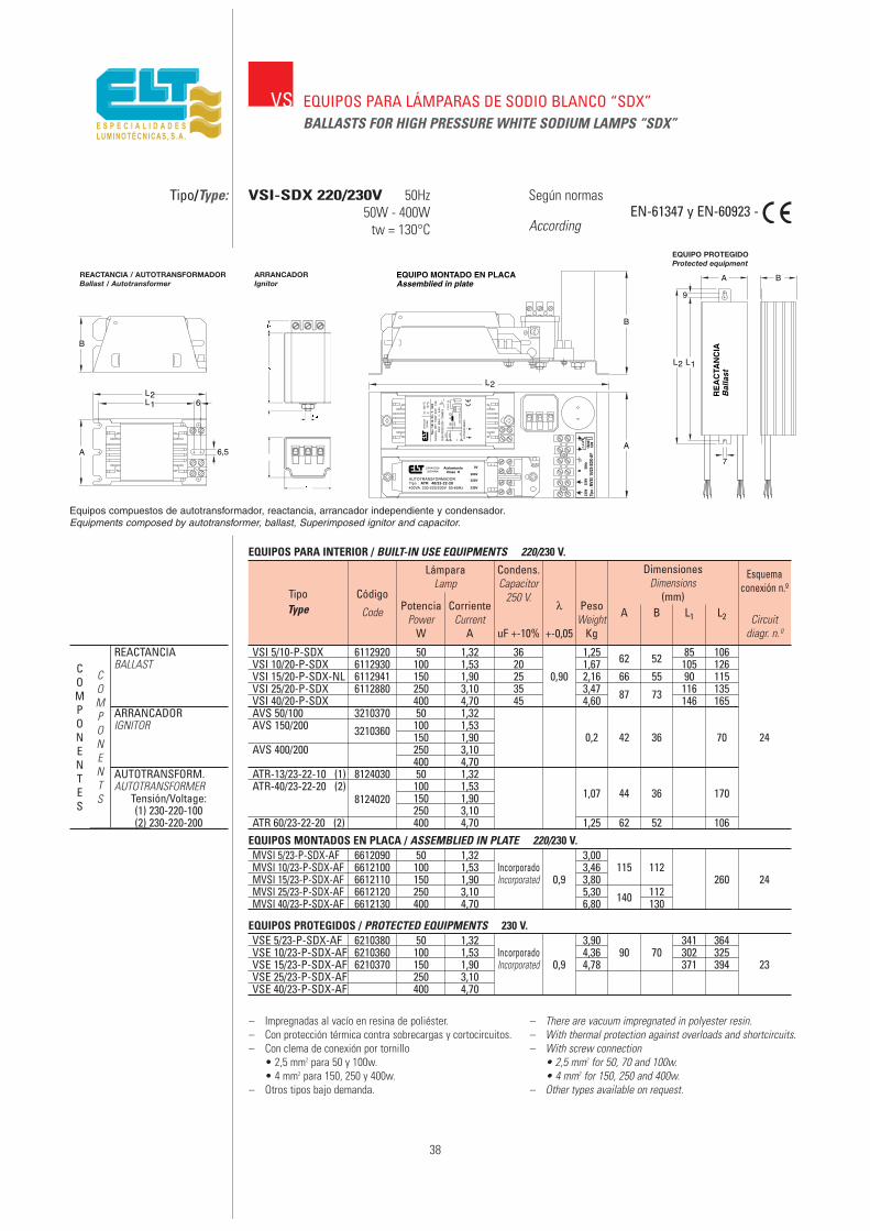
38
VSI 5/10-P-SDX 6112920 50 1,32 36 1,25 85 106VSI 10/20-P-SDX 6112930 100 1,53 20 1,67 62 52 105 126VSI 15/20-P-SDX-NL 6112941 150 1,90 25 0,90 2,16 66 55 90 115VSI 25/20-P-SDX 6112880 250 3,10 35 3,47 87 73 116 135VSI 40/20-P-SDX 400 4,70 45 4,60 146 165AVS 50/100 3210370 50 1,32AVS 150/200 3210360 100 1,53
150 1,90 0,2 42 36 70 24AVS 400/200 250 3,10
400 4,70ATR-13/23-22-10 (1) 8124030 50 1,32ATR-40/23-22-20 (2)
8124020100 1,53
1,07 44 36 170150 1,90250 3,10
ATR 60/23-22-20 (2) 400 4,70 1,25 62 52 106
VS EQUIPOS PARA LÁMPARAS DE SODIO BLANCO “SDX”BALLASTS FOR HIGH PRESSURE WHITE SODIUM LAMPS “SDX”
Tipo/Type: VSI-SDX 220/230V 50Hz50W - 400W
tw = 130°C
Según normas
AccordingEN-61347 y EN-60923 -
Tipo
: MVS
I15
/23-
SDX-
AF
230V
220V 0V
~20
0V31
AVS-
150/
200
2-2,
3 kV
AUT O
TRAN
SFO R
M ADO
R1
3
ZAR
AGO
ZA(E
SPAÑ
A)
2 00 V
50 H
zλ
: 0, 4
5
tw 1
3 0 º
C∆ t
7
0ºC
Lám
para
NH
T 1
50W
SD
X
1,9A
Tipo
: VS
I 15
/ 20
- T-
SD
X
A
R
0V
200V
220V
230V
AUTOTRANSFORMADORTipo : ATR 40/23-22-20400VA 230-220/200V 50-60Hz
ZARAGOZA(ESPAÑA)
AislamientoClase H
EQUIPO MONTADO EN PLACAAssemblied in plate
B
A
L2
RE
AC
TAN
CIA
Bal
last
7
A
9
B
L2 L1
– Impregnadas al vacío en resina de poliéster.– Con protección térmica contra sobrecargas y cortocircuitos.– Con clema de conexión por tornillo
• 2,5 mm2 para 50 y 100w.• 4 mm2 para 150, 250 y 400w.
– Otros tipos bajo demanda.
– There are vacuum impregnated in polyester resin.– With thermal protection against overloads and shortcircuits.– With screw connection
• 2,5 mm2 for 50, 70 and 100w.• 4 mm2 for 150, 250 and 400w.
– Other types available on request.
MVSI 5/23-P-SDX-AF 6612090 50 1,32 3,00MVSI 10/23-P-SDX-AF 6612100 100 1,53 Incorporado 3,46 115 112MVSI 15/23-P-SDX-AF 6612110 150 1,90 Incorporated 0,9 3,80 260 24MVSI 25/23-P-SDX-AF 6612120 250 3,10 5,30 140 112MVSI 40/23-P-SDX-AF 6612130 400 4,70 6,80 130
Código
Code
TipoType
EQUIPOS PARA INTERIOR / BUILT-IN USE EQUIPMENTS 220/230 V.
EQUIPOS MONTADOS EN PLACA / ASSEMBLIED IN PLATE 220/230 V.
VSE 5/23-P-SDX-AF 6210380 50 1,32 3,90 341 364VSE 10/23-P-SDX-AF 6210360 100 1,53 Incorporado 4,36 90 70 302 325VSE 15/23-P-SDX-AF 6210370 150 1,90 Incorporated 0,9 4,78 371 394 23VSE 25/23-P-SDX-AF 250 3,10VSE 40/23-P-SDX-AF 400 4,70
EQUIPOS PROTEGIDOS / PROTECTED EQUIPMENTS 230 V.
LámparaLamp
PotenciaPower
W
CorrienteCurrent
A
λ
+-0,05
PesoWeight
Kg
A B L1 L2 Circuitdiagr. n.º
Esquemaconexión n.º
uF +-10%
Condens.Capacitor
250 V.
DimensionesDimensions
(mm)
COMPONENTES
COMPONENTS
REACTANCIABALLAST
ARRANCADORIGNITOR
AUTOTRANSFORM.AUTOTRANSFORMER
Tensión/Voltage:(1) 230-220-100(2) 230-220-200
EQUIPO PROTEGIDOProtected equipment
L2L1
B
A
6
6,5
REACTANCIA Ballast
REACTANCIA / AUTOTRANSFORMADORBallast / Autotransformer
ARRANCADORIgnitor
Equipos compuestos de autotransformador, reactancia, arrancador independiente y condensador.Equipments composed by autotransformer, ballast, Superimposed ignitor and capacitor.
39
REACTANCIAS PARA LÁMPARAS DE HALOGENUROS METÁLICOS
BALLASTS FOR METAL HALIDE LAMPS
VH

40
Metal halide lamps
Metal halide lamps are made in a similar way to mercury vapourlamps, the difference being that, apart from mercury, they contain
halide from rare soils, such as Dysprosium, Holmium or Thulium,with which greater luminous efficiencies (95 Lm/w.) are obtained, as
well as better chromatic reproduction.
Although their operating conditions are similar to those of mercuryvapour lamps, the addition of halides requires a higher ignition
voltage than what normal networks can supply, so, apart from rareexceptions, they need a starter which provides peak voltage of
between 0.8 and 5 Kv.
The ignition period takes from 3 to 5 minutes, until the lamp givesthe luminous flow foreseen and the reignition period 10 to 20
minutes, depending on the type of light fitting and on the power ofthe lamp. For instantaneous reignition, peak voltages over 25 Kv
must be applied, so only lamps designed for this are adequate,bearing this voltage in mind when selecting the equipment and
materials of the installation.
Depending on the manufacturer of the lamp, for the same power, adifferent piece of equipment may be necessary, as they have
different electric characteristics. Therefore, the parameters of eachlamp must be borne very much in mind in order to connect it to the
right ballast and starter.
Operation
It must be taken into account that these lamps are more sensitive tovariations in the network voltage than other discharge lamps, andmust not differ from the rated voltage by more than 5%, as apart
from affecting the life of the lamp, the colour efficiency varies.Therefore, if voltages other than 220 or 230V. are foreseen, ballasts
for that network voltage, or bi-voltages, must be requested, so themost suitable one can be chosen at the time of the installation.
Lámparas de halogenuros metálicos
La constitución de las lámparas de halogenuros metálicos es similar a la de las de vapor de mercurio, de las que se diferencian en que,además de mercurio, contienen halogenuros de tierras raras, comoDysprosio, Holmio o Tulio, con lo que se obtienen mayoresrendimientos luminosos (95 Lm/w.), y sobre todo una mejorreproducción cromática.
Aunque sus condiciones de funcionamiento son similares a las de laslámparas de vapor de mercurio, la adición de los halogenuros hacenecesaria una tensión de encendido superior a la que las redesnormales pueden suministrar, por lo que necesitan, salvo rarasexcepciones, un arrancador que proporcione tensiones de pico entre0,8 y 5 Kv.
El período de arranque es de 3 a 5 minutos, hasta que la lámpara dael flujo luminoso previsto y el de reencendido de 10 a 20 minutos,dependiendo del tipo de luminaria y de la potencia de la lámpara.Para el reencendido instantáneo es necesario aplicar tensiones depico superiores a 25 Kv., por lo que sólo son adecuadas las lámparasprevistas para ello, teniendo en cuenta esta tensión al seleccionar losequipos y materiales de la instalación.
Según cuál sea el fabricante de la lámpara, para una misma potencia,puede ser necesario distinto equipo, puesto que tienen característicaseléctricas diferentes. Por ello, deben tenerse muy en cuenta losparámetros de cada lámpara para conectarla con la reactanciay arrancador adecuados.
Funcionamiento
Hay que tener en cuenta que estas lámparas son más sensibles a lasvariaciones de la tensión de red que otras de descarga, no debiendodiferir más del 5% del valor nominal, ya que además de afectar a laduración de la lámpara, varía el rendimiento de color de la misma. Porésto, si se prevén tensiones distintas de 220 ó 230V., se deben pedirreactancias para esa tensión de red, o bitensiones, de modo quepueda seleccionarse la más adecuada en el momento de la instalación.
130
120
110
100
90
VL
WLΦ
IL
80
70
Φ
Φ
92 96 100 104 108Vm(%)
%

41
Rectifying effect
The rectifying effect usually produced by the lamps during theignition in a transitory way and permanently at the end of their
lives, entails suitably dimensioning the ballasts and taking certain precautions in independent type starters to be used
with the ballasts.
With the current which is brought about by the one-directional typepressed, the impedance of the ballast is very low and the current
intensity much higher than the rated one, which causes dangerousheatings in the ballast and the starter which can endanger the
safety of the equipment.
To prevent this problem, the lamps must be replaced according to thelife expectation given by the manufacturer and the equipment must
have some kind of protection against this excess current. Theprotection can consist of an external thermal fuse or the use of
ballasts with internal thermal protection.
Efecto rectificador
El efecto rectificador que suelen producir las lámparas de formatransitoria en el encendido y de forma permanente al final de su vida,conlleva el dimensionar adecuadamente las reactancias y tomardeterminadas precauciones en los arrancadores de tipo independiente autilizar con las mismas.
Con la corriente que se origina del tipo unidireccional pulsada, laimpedancia de la reactancia es muy baja y la intensidad de corrientemucho más alta que la nominal, lo que ocasiona peligrososcalentamientos en la reactancia y el arrancador que pueden poner enpeligro la seguridad del equipo.
Para prevenir este problema, las lámparas deben ser reemplazadassegún la expectativa de vida indicada por el fabricante y los equiposdeben llevar alguna protección contra esta sobrecorriente. La protecciónpuede consistir en un fusible térmico externo o en el uso de reactanciascon protección térmica interna.
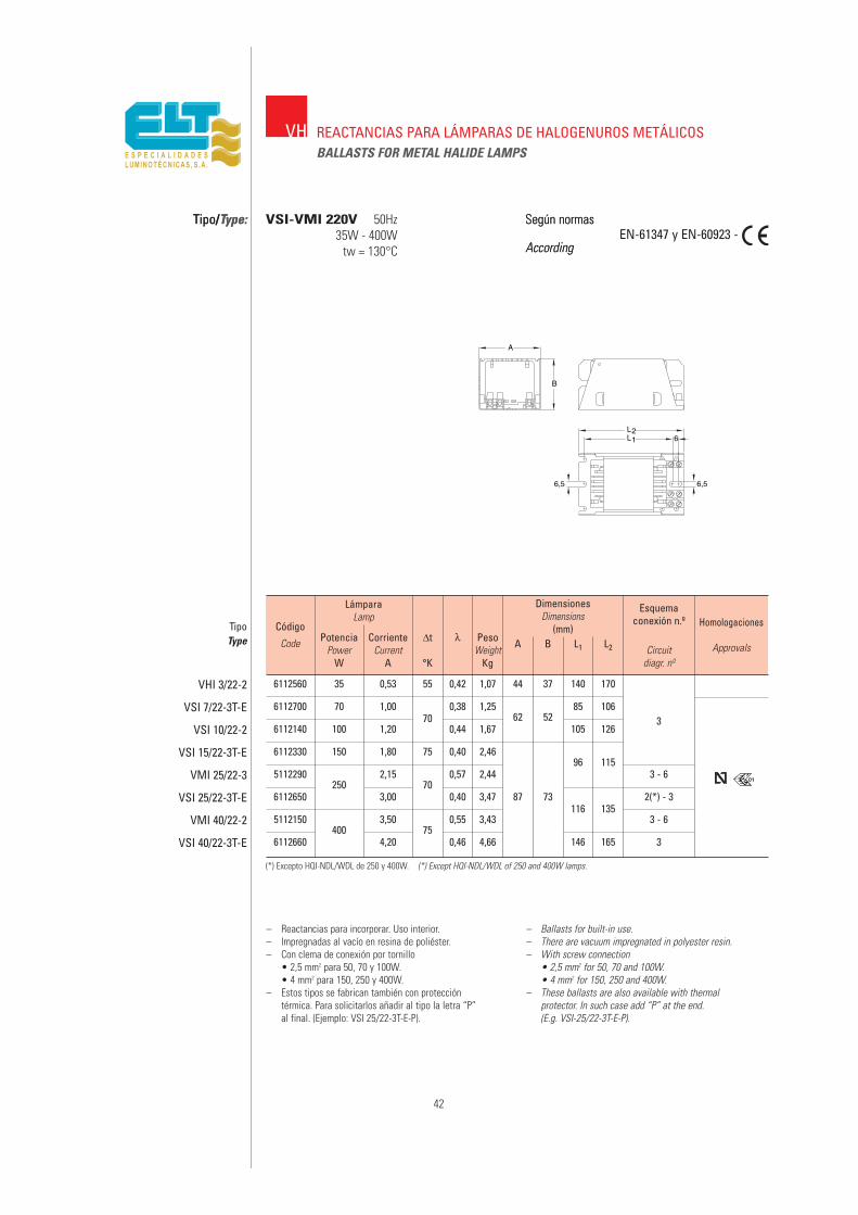
6112560 35 0,53 55 0,42 1,07 44 37 140 170
6112700 70 1,00 0,38 1,25 85 106
6112140 100 1,2070
0,44 1,6762 52
105 1263
6112330 150 1,80 75 0,40 2,4696 115
5112290250
2,1570
0,57 2,44 3 - 6
6112650 3,00 0,40 3,47 87 73 2(*) - 3
5112150400
3,5075
0,55 3,43116 135
3 - 6
6112660 4,20 0,46 4,66 146 165 3
42
Tipo/Type: Según normas
AccordingEN-61347 y EN-60923 -
Formato 1
L2L1
A
B
6
6,5 6,5
– Reactancias para incorporar. Uso interior.– Impregnadas al vacío en resina de poliéster.– Con clema de conexión por tornillo
• 2,5 mm2 para 50, 70 y 100W.• 4 mm2 para 150, 250 y 400W.
– Estos tipos se fabrican también con proteccióntérmica. Para solicitarlos añadir al tipo la letra “P”al final. (Ejemplo: VSI 25/22-3T-E-P).
– Ballasts for built-in use.– There are vacuum impregnated in polyester resin.– With screw connection
• 2,5 mm2 for 50, 70 and 100W.• 4 mm2 for 150, 250 and 400W.
– These ballasts are also available with thermalprotector. In such case add “P” at the end.(E.g. VSI-25/22-3T-E-P).
Código
Code
TipoType
VHI 3/22-2
VSI 7/22-3T-E
VSI 10/22-2
VSI 15/22-3T-E
VMI 25/22-3
VSI 25/22-3T-E
VMI 40/22-2
VSI 40/22-3T-E
LámparaLamp
PotenciaPower
W
CorrienteCurrent
A
∆t
°K
λ PesoWeight
Kg
A B L1 L2 Circuitdiagr. nº
Esquemaconexión n.º Homologaciones
Approvals
DimensionesDimensions
(mm)
VH
Tipo/Type: VSI-VMI 220V 50Hz35W - 400W
tw = 130°C
Según normas
According
REACTANCIAS PARA LÁMPARAS DE HALOGENUROS METÁLICOSBALLASTS FOR METAL HALIDE LAMPS
(*) Excepto HQI-NDL/WDL de 250 y 400W. (*) Except HQI-NDL/WDL of 250 and 400W lamps.
01
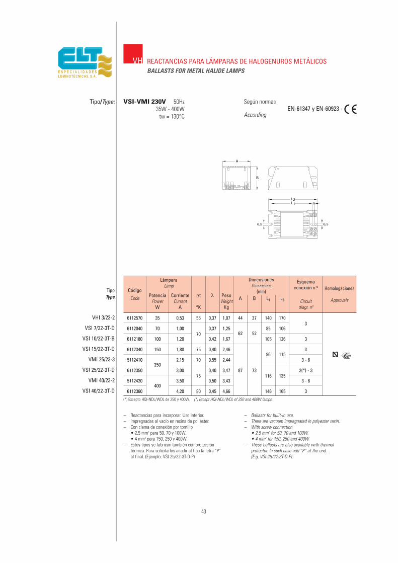
6112570 35 0,53 55 0,37 1,07 44 37 140 1703
6112040 70 1,0070
0,37 1,25 85 106
6112180 100 1,20 0,42 1,6762 52
105 126 3
6112340 150 1,80 75 0,40 2,4696 115
3
5112410250
2,15 70 0,55 2,44 3 - 6
6112350 3,00 0,40 3,47 87 73 2(*) - 3
5112420400
3,5075
0,50 3,43116 135
3 - 6
6112360 4,20 80 0,45 4,66 146 165 3
43
Tipo/Type:
Formato 1
L2L1
A
B
6
6,5 6,5
– Reactancias para incorporar. Uso interior.– Impregnadas al vacío en resina de poliéster.– Con clema de conexión por tornillo
• 2,5 mm2 para 50, 70 y 100W.• 4 mm2 para 150, 250 y 400W.
– Estos tipos se fabrican también con proteccióntérmica. Para solicitarlos añadir al tipo la letra “P”al final. (Ejemplo: VSI 25/22-3T-D-P)
– Ballasts for built-in use.– There are vacuum impregnated in polyester resin.– With screw connection
• 2,5 mm2 for 50, 70 and 100W.• 4 mm2 for 150, 250 and 400W.
– These ballasts are also available with thermalprotector. In such case add “P” at the end.(E.g. VSI-25/22-3T-D-P).
Código
Code
TipoType
VHI 3/23-2
VSI 7/22-3T-D
VSI 10/22-3T-B
VSI 15/22-3T-D
VMI 25/23-3
VSI 25/22-3T-D
VMI 40/23-2
VSI 40/22-3T-D
LámparaLamp
PotenciaPower
W
CorrienteCurrent
A
∆t
°K
λ PesoWeight
Kg
A B L1 L2 Circuitdiagr. nº
Esquemaconexión n.º Homologaciones
Approvals
DimensionesDimensions
(mm)
VH
VSI-VMI 230V 50Hz35W - 400W
tw = 130°C
Según normas
AccordingEN-61347 y EN-60923 -
REACTANCIAS PARA LÁMPARAS DE HALOGENUROS METÁLICOSBALLASTS FOR METAL HALIDE LAMPS
01
(*) Excepto HQI-NDL/WDL de 250 y 400W. (*) Except HQI-NDL/WDL of 250 and 400W lamps.
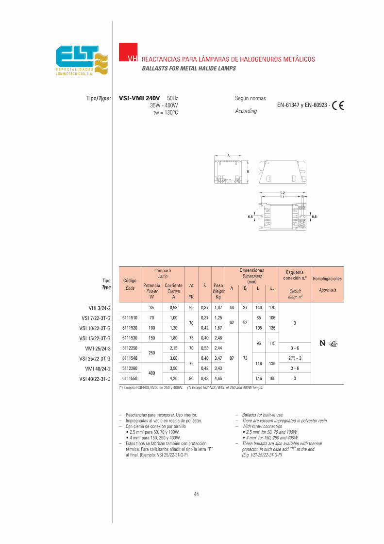
35 0,53 55 0,37 1,07 44 37 140 170
6111510 70 1,00 0,37 1,25 85 106
6111520 100 1,2070
0,42 1,6762 52
105 1263
6111530 150 1,80 75 0,40 2,4696 115
5112250250
2,15 70 0,53 2,44 3 - 6
6111540 3,00 0,40 3,47 87 73116 135
2(*) - 3
5112260400
3,5075
0,48 3,43 3 - 6
6111550 4,20 80 0,43 4,66 146 165 3
44
Tipo/Type:
Formato 1
L2L1
A
B
6
6,5 6,5
– Reactancias para incorporar. Uso interior.– Impregnadas al vacío en resina de poliéster.– Con clema de conexión por tornillo
• 2,5 mm2 para 50, 70 y 100W.• 4 mm2 para 150, 250 y 400W.
– Estos tipos se fabrican también con proteccióntérmica. Para solicitarlos añadir al tipo la letra “P”al final. (Ejemplo: VSI 25/22-3T-G-P).
– Ballasts for built-in use.– There are vacuum impregnated in polyester resin.– With screw connection
• 2,5 mm2 for 50, 70 and 100W.• 4 mm2 for 150, 250 and 400W.
– These ballasts are also available with thermalprotector. In such case add “P” at the end.(E.g. VSI-25/22-3T-G-P).
Código
Code
TipoType
VHI 3/24-2
VSI 7/22-3T-G
VSI 10/22-3T-G
VSI 15/22-3T-G
VMI 25/24-3
VSI 25/22-3T-G
VMI 40/24-2
VSI 40/22-3T-G
LámparaLamp
PotenciaPower
W
CorrienteCurrent
A
∆t
°K
λ PesoWeight
Kg
A B L1 L2 Circuitdiagr. nº
Esquemaconexión n.º Homologaciones
Approvals
DimensionesDimensions
(mm)
VH
VSI-VMI 240V 50Hz35W - 400W
tw = 130°C
Según normas
AccordingEN-61347 y EN-60923 -
REACTANCIAS PARA LÁMPARAS DE HALOGENUROS METÁLICOSBALLASTS FOR METAL HALIDE LAMPS
01
(*) Excepto HQI-NDL/WDL de 250 y 400W. (*) Except HQI-NDL/WDL of 250 and 400W lamps.
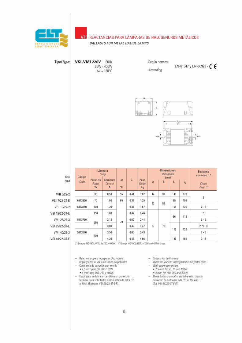
35 0,53 55 0,41 1,07 44 37 140 1703
6113920 70 1,00 65 0,38 1,25 85 106
6113860 100 1,20 0,44 1,6762 52
105 126 2 - 3
150 1,80 0,42 2,4696 115
3
5113780250
2,1570
0,60 2,44 3 - 6
3,00 0,42 3,47 87 73116 135
2(*) - 3
5113670 3,50 0,60 3,43 3 - 6400
4,20 0,47 4,66 146 165 2 - 3
45
Tipo/Type:EN-61347 y EN-60923 -
Formato 1
L2L1
A
B
6
6,5 6,5
– Reactancias para incorporar. Uso interior.– Impregnadas al vacío en resina de poliéster.– Con clema de conexión por tornillo
• 2,5 mm2 para 50, 70 y 100W.• 4 mm2 para 150, 250 y 400W.
– Estos tipos se fabrican también con proteccióntérmica. Para solicitarlos añadir al tipo la letra “P”al final. (Ejemplo: VSI 25/22-3T-E-P).
– Ballasts for built-in use.– There are vacuum impregnated in polyester resin.– With screw connection
• 2,5 mm2 for 50, 70 and 100W.• 4 mm2 for 150, 250 and 400W.
– These ballasts are also available with thermalprotector. In such case add “P” at the end.(E.g. VSI-25/22-3T-E-P).
Código
Code
TipoType
VHI 3/22-2
VSI 7/22-3T-E
VSI 10/22-2
VSI 15/22-3T-E
VMI 25/22-3
VSI 25/22-3T-E
VMI 40/22-2
VSI 40/22-3T-E
LámparaLamp
PotenciaPower
W
CorrienteCurrent
A
∆t
°K
λ PesoWeight
Kg
A B L1 L2 Circuitdiagr. nº
Esquemaconexión n.º
DimensionesDimensions
(mm)
VH
VSI-VMI 220V 60Hz35W - 400W
tw = 130°C
Según normas
According
REACTANCIAS PARA LÁMPARAS DE HALOGENUROS METÁLICOSBALLASTS FOR METAL HALIDE LAMPS
(*) Excepto HQI-NDL/WDL de 250 y 400W. (*) Except HQI-NDL/WDL of 250 and 400W lamps.
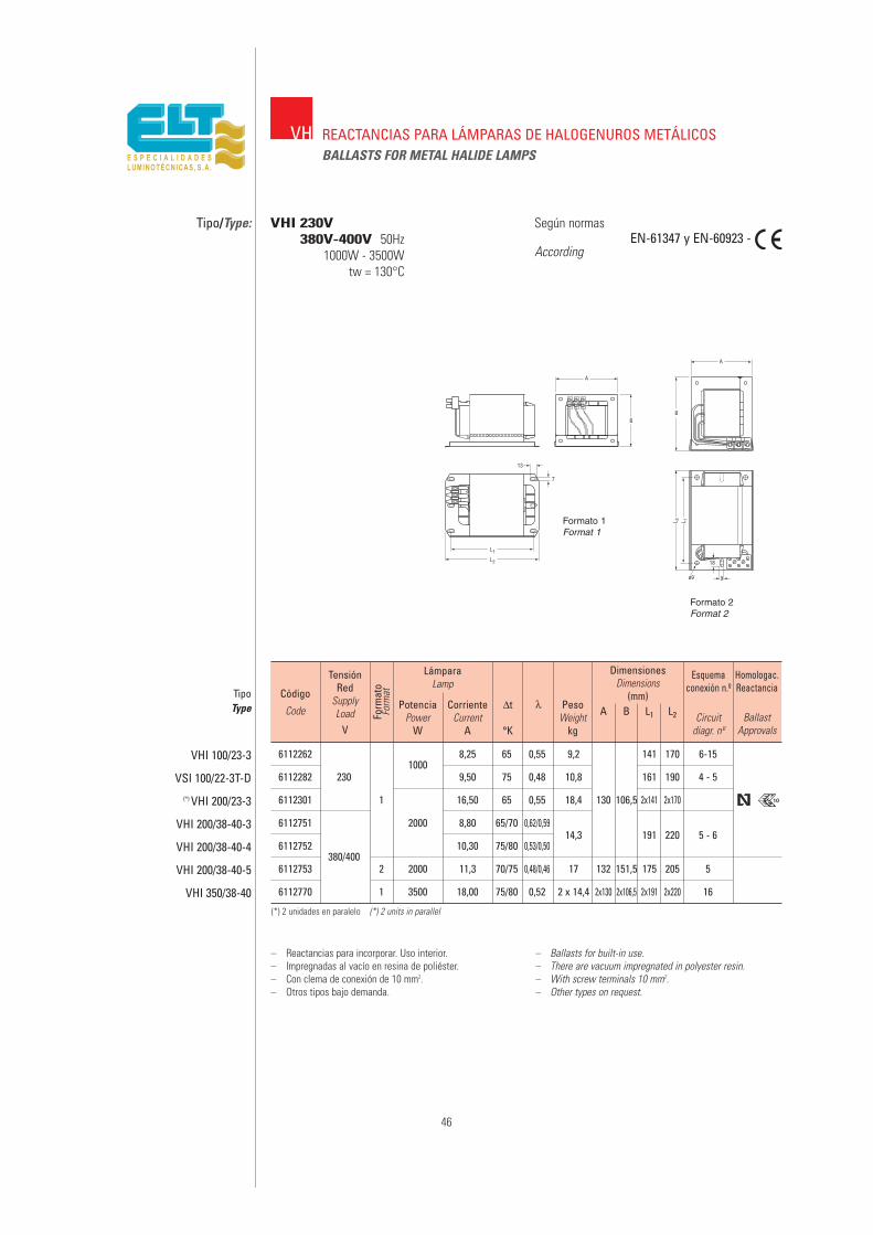
61122621000
8,25 65 0,55 9,2 141 170 6-15
6112282 230 9,50 75 0,48 10,8 161 190 4 - 5
6112301 1 16,50 65 0,55 18,4 130 106,5 2x141 2x170
6112751 2000 8,80 65/70 0,62/0,5914,3 191 220 5 - 6
6112752380/400
10,30 75/80 0,53/0,50
6112753 2 2000 11,3 70/75 0,48/0,46 17 132 151,5 175 205 5
6112770 1 3500 18,00 75/80 0,52 2 x 14,4 2x130 2x106,5 2x191 2x220 16
46
VH REACTANCIAS PARA LÁMPARAS DE HALOGENUROS METÁLICOSBALLASTS FOR METAL HALIDE LAMPS
Tipo/Type: VHI 230V380V-400V 50Hz
1000W - 3500Wtw = 130°C
Según normas
AccordingEN-61347 y EN-60923 -
– Reactancias para incorporar. Uso interior.– Impregnadas al vacío en resina de poliéster.– Con clema de conexión de 10 mm2.– Otros tipos bajo demanda.
– Ballasts for built-in use.– There are vacuum impregnated in polyester resin.– With screw terminals 10 mm2.– Other types on request.
Código
Code
TensiónRed
SupplyLoad
V
TipoType
VHI 100/23-3
VSI 100/22-3T-D(*) VHI 200/23-3
VHI 200/38-40-3
VHI 200/38-40-4
VHI 200/38-40-5
VHI 350/38-40
LámparaLamp
PotenciaPower
W
CorrienteCurrent
A
∆t
°K
λ PesoWeight
kg
A B L1 L2 Circuitdiagr. nº
BallastApprovals
Esquemaconexión n.º
Homologac.Reactancia
DimensionesDimensions
(mm)
(*) 2 unidades en paralelo (*) 2 units in parallel
10
Form
ato
Form
at
Formato 1Format 1
Formato 2Format 2

47
VH EQUIPOS COMPLETOS PARA LÁMPARAS DE HALOGENUROS METÁLICOSASSEMBLIES FOR METAL HALIDE LAMPS
Tipo/Type: VSI-VMI AF 220V y 230V 50Hz70W - 400W
tw = 130°C
Según normas
AccordingEN-61347 y EN-60923 -
– Montajes para incorporar en alojamientos o recintosprotegidos. Uso interior.
– Incluyen reactancia, condensador y arrancador de tipoindependiente.
– También se fabrican con protección térmica incorporada.– Reactancias impregnadas al vacío en resina de políester– Con clema de conexión por tornillo
• 2,5 mm2 para 50, 70 y 100W.• 4 mm2 para 150, 250 y 400W.
– Otros tipos bajo demanda.
– Ballasts for built-in use.– Equipment comprising ballasts, capacitor and
superimposed ignitor.– Also available with thermal protector.– The ballasts are vacuum impregnated in polyester resin.– With screw connection
• 2,5 mm2 for 50, 70 and 125W.• 4 mm2 for 150, 250 and 400W.
– Other types on request.
6212010 70 1,00 0,4070
1,5562 111
85 106
6212100 100 1,20 0,55 2,00 72 105 126 17
6212020 150 1,80 0,81 75 2,80 135
2502,15 1,36
0,902,64
96 115
6212030 3,00 1,3870
3,9387
3,50 2,003,62 145 91 116 135 7
6212090 400 75 3,93
6212120 4,20 2,10 5,10 146 165
Código
Code
TipoType
220V
230V
VSI 7/22-3AF-150VSI 10/22-2AF-150VSI 15/22-3AF-150
VMI 25/22-2AF-002VSI 25/22-3AF-400
VMI 40/22-2AF-002VMI 40/22-2AF-400VSI 40/22-3AF-400
LámparaLamp
PotenciaPower
W
CorrienteCurrent
A
∆t
°K
CorrienteCurrent
A
LíneaSupply
λ PesoWeight
Kg
A1 A2 B L1 L2 Circuitdiagr. nº
Esquemaconexión n.º
Approvals
Homologac.Dimensiones
Dimensions(mm)
6212130 70 1,00 0,40 1,6662 111
85 106
6212140 100 1,20 0,5570
2,08 72 105 126 17
6212150 150 1,80 0,78 75 2,82 135
5612563250
2,15 1,300,90
70 2,6496 115
6212160 3,00 1,33 3,93873,50 75 3,62 145 91 116 135 7
6212180 400 2,00 3,93
6212190 4,20 80 5,10 146 165
VSI 7/23-3AF-150VSI 10/23-2AF-150VSI 15/23-3AF-150
VMI 25/23-3AF-002VSI 25/23-3AF-400
VMI 40/23-2AF-002VMI 40/23-2AF-400VSI 40/23-2AF-400
01
(componentes)(components)
(componentes)(components)
01

6212705 70 0,98 0,40 1,50 85 158
6212714 100 1,20 0,5570
1,9262 77
105 178
6212731 150 1,80 0,79 75 2,91
62127832,10 1,30 70
2,50 96 1757
6212782 250 2,5587 76
6212781 3 1,33 75 3,92
6212793400 3,50 1,80 75
3,42 116 195
6212792 3,92
48
VSI-ARCEVHI-ARCE
EQUIPOS COMPLETOS ENCHUFABLES PARA LÁMPARASDE VAPOR DE HALOGENUROS METÁLICOSASSEMBLIES FOR METAL HALIDE LAMPS
Tipo/Type: VSI-ARCE 230V 50HzVHI-ARCE 70 - 400W
tw = 130°C
Según normas
AccordingEN-61347 y EN-60923
EN-60927
– Ballast for built-in use.– Ballast and subset which plugs in are included.
Equipment comprising ignitor, capacitor and termi-nal for the net and lamp.
– The equipments finished in 002 are only valid forlamps with lighting voltage <800V.
– The subset is easily separable from the ballast.– Also available with thermal protector.– To demand, please, add the letter -P at the end of
each type. (Ex. VSI 15/23-ARCE-150-P).– It is obligatory to use the central fixing hole
(*) to assure the continuity of the earth termi-nal.
– Quick installation. Only connecting to the net andlamp.
– There are vacuum impregnated in polyester resin.– Connection terminals by screw 2.5 mm.– Other voltages and frequencies on request.
Código
Code
TipoType
VSI 7/23-ARCE-150
VSI 10/23-ARCE-150
VSI 15/23-ARCE-150
VHI 25/23-ARCE-002
VHI 25/23-ARCE-400
VSI 25/23-ARCE-400
VHI 40/23-ARCE-002
VHI 40/23-ARCE-400
LámparaLamp
LíneaSupply
PotenciaPower
W
CorrienteCurrent
A
CorrienteCurrent
A
∆t
°K
λ PesoWeight
Kg
A B L1 L2 Circuitdiagr. n.º
Esquemaconexión
n.º Homol
Approvals
DimensionesDimensions
(mm)
01
230 V.
– Equipos para incorporar en alojamientos o recintosprotegidos. Uso interior.
– Incluyen reactancia y subconjunto enchufable queincorpora arrancador, condensador y bornas parared y lámpara.
– Los equipos terminados en 002 sólo son válidospara lámparas de tensión de encendido <800V.
– El subconjunto es fácilmente separable de la reac-tancia.
– También se fabrican con protección térmicaincorporada. Para su solicitud añadir la letra -P alfinal de cada tipo. (ej. VSI 15/23-ARCE-150-P).
– Es obligatorio utilizar el anclaje central (*)para asegurar la continuidad de la toma detierra.
– Gran rapidez de instalación. Sólo conectar red ylámpara.
– Reactancias impregnadas al vacío en resina depoliéster.
– Clemas de conexión por tornillo de 2,5 mm2.– Otras tensiones y frecuencias bajo demanda.
0,90+
0,0501
01
70 y 100W 150 - 250 y 400W

6110330 70 1,00 0,38 1,4069 60,3
120 132 3
6110170 100 1,20 0,44 1,95 106 118 2(*) - 3
6110360 150 1,80 70 0,402,60 95 111
3
5110370250
2,15 0,57 3 - 6
6110350 3,00 0,40 3,66 92 83115 131
2(*) - 3 2
5110380 400 3,50 75 0,55 3,66 3 - 6
6110370 4,20 70 0,46 5,00 145 161 2(*) - 3
Tipo/Type:
– Reactancias para intemperie. Uso exterior.– Impregnadas al vacío en resina de poliéster.– Encapsuladas en resina de poliuretano.– Con clema de conexión por tornillo
• 2,5 mm2 para 50, 70 y 100W.• 4 mm2 para 150, 250 y 400W.
– Estos tipos se fabrican también con proteccióntérmica. Para solicitarlos añadir al tipo la letra “P”al final. (Ejem.: VSE 25/22-3T-E-P).
– Ballasts for outdoor use.– There are vacuum impregnated in polyester resin.– Encapsulated in polyurethane resin.– With screw connection
• 2,5 mm2 for 50, 70 and 100W.• 4 mm2 for 150, 250 and 400W.
– These ballasts are also available with thermalprotector. In such case add “P” at the end.(E.g. VSE-25/22-3T-E-P).
Código
Code
TipoType
VSE 7/22-3T-E
VSE 10/22-EA
VSE 15/22-3T-E
VME 25/22-EA
VSE 25/22-3T-E
VME 40/22-EA
VSE 40/22-3T-E
LámparaLamp
PotenciaPower
W
CorrienteCurrent
A
∆t
°K
λ PesoWeight
Kg
A B L1 L2 Circuitdiagr. nº
Esquemaconexión n.º
DimensionesDimensions
(mm)
VH
Según normas
AccordingEN-61347 y EN-60923 -
REACTANCIAS PARA LÁMPARAS DE HALOGENUROS METÁLICOSBALLASTS FOR METAL HALIDE LAMPS
VSE-VME encapsulado/encapsulated220 y 230V 50Hz
70W - 400Wtw = 130°C
220V
6110181 70 1,00 0,37 1,4069 60,3
120 132 3 1
6110171 100 1,20 0,42 1,95 106 118 2(*) - 3
6110201 150 1,80 70 0,382,60 95 111
3
5110390250
2,15 0,55 3 - 6
6110211 3,00 0,38 3,66 92 83115 131
2(*) - 3 2
5110400400
3,50 75 0,53 3,66 3 - 6
6110221 4,20 70 0,44 5,00 145 161 2(*) - 3
VSE 7/23-EA
VSE 10/23-EA
VSE 15/23-EA
VME 25/22-EA
VSE 25/23-EA
VME 40/23-EA
VSE 40/23-EA
230V
(*) Excepto HQI-NDL/WDL de 250 y 400W. (*) Except HQI-NDL/WDL of 250 and 400W lamps.
49
8
L2
5,5
L1
BA
Form
ato
Form
at
Formato 1Format 1
Formato 2Format 2
1

50
(*) Condensador y Arrancador incorporado. (*) Capacitor and ignitor incorporated.
IP55EQUIPOS COMPLETOS EN COFRE IP55 PARA SODIO ALTA PRESIÓNY HALOGENUROS METÁLICOSELECTROMAGNETIC CONTROL GEAR FOR HIGH PRESSURE SODIUMAND METAL HALIDE LAMPS MOUNTED IN IP 55 BOX
Tipo/Type: VSE 600W - 1000W 230VVHE 1000W - 2000W 380 - 400V
50Hztw = 130°C
Según normas
AccordingEN-61347 y EN-60923 -
– Caja de aluminio inyectado.– Incluye reactancia, condensador y arrancador y bornes
para red y lámpara.– Otros tipos bajo demanda.
– Die-Cast aluminium box.– This gear includes: Ballast, ignitor, capacitor and
terminal block for mains supply and lamp connectionsfully assembled.
– Other types on request.
6210751600 6,20 230 3 50 65/250
AVS 100-1 11,10
0,9 AVS 1000 11,40
62103231000 10,30 230 5
+0,0540 100/250
AVS 100-1 14,70
6210322 AVS 1000 15
Código
Code
TipoType
VSE 60/23-100-AF
VSE 60/23-1000-AF
VSE 100/23-100-AF
VSE 100/23-1000-AF
LámparaLamp
PotenciaPower
W
CorrienteCurrent
A
ta
°K
TensiónVoltage
V
CorrienteCurrent
A
LíneaSupply
λ
62103271000
8,25 545
72/250 AH 002-1 12,10
6210321 9,50 230 5 85/250 AVS 1000 14,70
6210306 16,50 10,3 35 125/250 AH 002-1 19
62103038,80 5,6/5,4
0,945 37/400
16,75
62103022000
+0,05 AH 005 17
621030010,30 380/400 40
17
6210304 AVS 2000/380 17,40
62103056/5,8 60/400
11,30 30AVS 2000/380
19,30
VHE 100/23-002-AF
VHE 100/23-1000-AF
VHE 200/23-002-AF
VHE 200/38-40-3AF
VHE 200/38-40-005-AF
VHE 200/38-40-4AF
VHE 200/38-40-4-2000
VHE 200/38-40-5
VHE 2000/38-5-AF-2000
PesoWeight
Kg
Ignitor
(*)(
Capacitor(*)
µF/V
Arrancador(*)
Condensador(*)
LÁMPARAS VAPOR SODIO ALTA PRESIÓN / HIGH PRESSURE SODIUM VAPOUR LAMPS
LÁMPARAS HALOGENUROS METÁLICOS / METAL HALIDE LAMPS

51
REACTANCIAS PARA LÁMPARAS DE VAPORDE SODIO A BAJA PRESIÓN
BALLASTS FOR LOW PRESSURESODIUM VAPOUR LAMPS
VSB
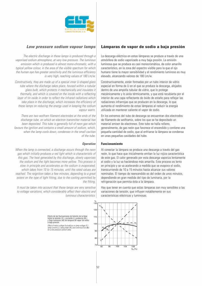
52
Low pressure sodium vapour lamps
The electric discharge in these lamps is produced through avaporised sodium atmosphere, at very low pressure. The luminous
emission which is produced is almost mono-chromatic, with atypical yellow colour, in the area of the visible spectrum for whichthe human eye has greater sensitivity and the luminous efficiency
is very high, reaching values of 180 Lm/w.
Constructively, they are made up of a special inner U-shaped glasstube where the discharge takes place, housed within a tubular
glass bulb, which protects it mechanically and insulates itthermally, and which is covered on the inside with a reflecting
layer of tin oxide in order to reflect the infrared radiations whichtake place in the discharge, which increases the efficiency of
these lamps on reducing the energy used in keeping the sodiumvapour warrn.
There are two wolfram filament electrodes at the ends of thedischarge tube, on which an electron transmitter material hasbeen deposited. This tube is generally full of neon gas which
favours the ignition and contains a small amount of sodium, which,when the lamp cools down, condenses in the small cavities
of the tube.
Operation
When the lamp is connected, a discharge occurs through the neongas which initially produces a red light which is characteristic ofthis gas. The heat generated by this discharge, slowly vaporises
the sodium and the light becomes more yellow. This process isslow in principle and accelerates as the sodium is evaporated,
which takes from 10 to 15 minutes, until the rated values arereached. The reignition takes a few minutes, depending to a greatextent on the type of light fitting, due to the cooling permitted by
the fitting.
It must be taken into account that these lamps are very sensitiveto voltage variations, which considerably affect their electric and
luminous characteristics.
Lámparas de vapor de sodio a baja presión
La descarga eléctrica en estas lámparas se produce a través de unaatmósfera de sodio vaporizado a muy baja presión. La emisiónluminosa que se produce es casi monocromática, de color amarillocaracterístico, en la zona del espectro visible para la que el ojohumano tiene la mayor sensibilidad y el rendimiento luminoso es muyelevado, alcanzando valores de 180 Lm/w.
Constructivamente, están formadas por un tubo interior de vidrioespecial en forma de U en el que se produce la descarga, alojadosdentro de una ampolla tubular de vidrio, que lo protegemecánicamente y lo aisla térmicamente, y que está recubierta por elinterior de una capa reflectante de óxido de estaño para reflejar lasradiaciones infrarrojas que se producen en la descarga, lo queaumenta el rendimiento de estas lámparas al reducir la energíautilizada en mantener caliente el vapor de sodio.
En los extremos del tubo de descarga se encuentran dos electrodosde filamento de wolframio, sobre los que se ha depositado unmaterial emisor de electrones. Este tubo se halla relleno,generalmente, de gas neón que favorece el encendido y contiene unapequeña cantidad de sodio, que al enfriarse la lámpara se condensaen unas pequeñas cavidades del tubo.
Funcionamiento
Al conectar la lámpara se produce una descarga a través del gasneón, lo que hace que inicialmente emitan la luz rojiza característicade este gas. El calor generado por esta descarga vaporiza lentamenteel sodio y la luz va haciéndose más amarilla. Este proceso es lentoen principio y se va acelerando a medida que se evapora el sodio,transcurriendo de 10 a 15 minutos hasta alcanzar sus valoresnominales. El tiempo de reencendido es del orden de unos minutos,dependiendo en gran medida del tipo de luminaria, por larefrigeración que permita ésta a la lámpara.
Hay que tener en cuenta que estas lámparas son muy sensibles a lasvariaciones de tensión, que influyen notablemente en suscaracterísticas eléctricas y luminosas.
130
120
110
100
90
VL
WL
Φ
IL80
70
Φ
Φ
92 96 100 104 108Vm(%)
%
53
The ignition voltage of these lamps rises above 350V, to around600V, depending on the types, so a supply appliance is required
which, apart from controlling the intensity, raises the networkvoltage to the necessary value, normally using autotransformer
ballasts for this.
Some lamp powers, whose operating voltage is less than thenetwork voltage, permit the use of hybrid systems, choke
ballasts instead of autotransformer and electronic starter whichwill produce high voltage pulses which initiate the discharge on
the inside of the lamp, the ballast carrying out the only controlfunction of the intensity of the circuit.
La tensión de encendido de estas lámparas se eleva por encima de350 V, hasta unos 600V, según los tipos, por lo que es preciso unaparato de alimentación que, además de controlar la intensidad,eleve la tensión de red al valor necesario, utilizándose para esto,normalmente, reactancias autotransformadoras.
Algunas potencias de lámpara, cuya tensión de funcionamiento esinferior a la tensión de la red, permiten la utilización de sistemashíbridos, reactancia de choque en lugar de autotransformador yarrancador electrónico que produzca impulsos de tensión elevada queinicie la descarga en el interior de la lámpara, realizando lareactancia la única función de control de la intensidad del circuito.
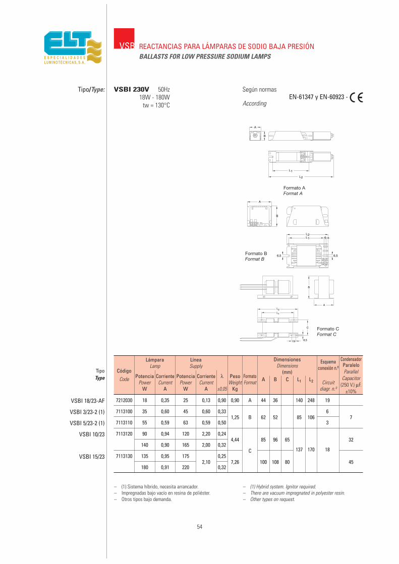
7212030 18 0,35 25 0,13 0,90 0,90 A 44 36 140 248 19
7113100 35 0,60 45 0,60 0,331,25 B 62 52 85 106
67
7113110 55 0,59 63 0,59 0,50 3
7113120 90 0,94 120 2,20 0,244,44 85 96 65 32
140 0,90 165 2,00 0,32C 137 170 18
7113130 135 0,95 1752,10
0,257,26 100 108 80 45
180 0,91 220 0,32
54
VSB REACTANCIAS PARA LÁMPARAS DE SODIO BAJA PRESIÓNBALLASTS FOR LOW PRESSURE SODIUM LAMPS
Tipo/Type: VSBI 230V 50Hz18W - 180W
tw = 130°C
Según normas
AccordingEN-61347 y EN-60923 -
B
A
L2
L1
Formato 1
L2L1
A
B
6
6,5 6,5
B
L1
L2
A
C
6,519
– (1) Sistema híbrido, necesita arrancador.– Impregnadas bajo vacío en resina de poliéster.– Otros tipos bajo demanda.
– (1) Hybrid system. Ignitor required.– There are vacuum impregnated in polyester resin.– Other types on request.
Formato BFormat B
Formato CFormat C
Formato AFormat A
Código
Code
TipoType
VSBI 18/23-AF
VSBI 3/23-2 (1)
VSBI 5/23-2 (1)
VSBI 10/23
VSBI 15/23
LámparaLamp
PotenciaPower
W
CorrienteCurrent
A
LíneaSupply
PotenciaPower
W
CorrienteCurrent
A
λ
±0,05
PesoWeight
Kg
FormatoFormat A B C L1 L2 Circuit
diagr. n.º
Esquemaconexión n.º
ParallelCapacitor
(250 V.) µF. ±10%
CondensadorParalelo
DimensionesDimensions
(mm)
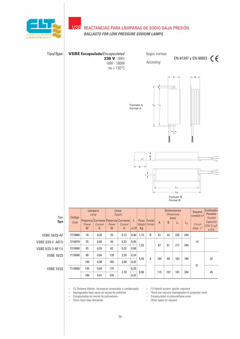
7210060 18 0,35 25 0,13 0,90 1,73 B 61 42 220 240
7210070 35 0,60 45 0,23 0,951,53 67 61 217 240
14
7210080 55 0,59 63 0,32 0,90
7110040 90 0,94 120 2,20 0,245,55 A 104 89 163 186 32
140 0,90 165 2,00 0,3221
7110050 135 0,95 1752,10
0,258,90 115 107 181 204 45
180 0,91 220 0,32
55
VSB REACTANCIAS PARA LÁMPARAS DE SODIO BAJA PRESIÓNBALLASTS FOR LOW PRESSURE SODIUM LAMPS
Tipo/Type: Según normas
AccordingEN-61347 y EN-60923 -
L1L2
7
A
9
B
A
B
7
L2
L1
– (1) Sistema híbrido, incorporan arrancador y condensador.– Impregnadas bajo vacío en resina de poliéster.– Encapsuladas en resina de poliuretano.– Otros tipos bajo demanda.
– (1) Hybrid system. Ignitor required.– There are vacuum impregnated in polyester resin.– Encapsulated in polyurethane resin.– Other types on request.
Código
Code
TipoType
VSBE 18/23-AF
VSBE 3/23-2 -AF(1)
VSBE 5/23-2-AF (1)
VSBE 10/23
VSBE 15/23
LámparaLamp
PotenciaPower
W
CorrienteCurrent
A
LíneaSupply
PotenciaPower
W
CorrienteCurrent
A
λ
±0,05
PesoWeight
Kg
FormatoFormat A B L1 L2 Circuit
diagr. n.º
Esquemaconexión n.º
ParallelCapacitor
(250 V.) µF. ±10%
CondensadorParalelo
DimensionesDimensions
(mm)
Formato BFormat B
Formato AFormat A
VSBE Encapsulado/Encapsulated230 V 50Hz
18W - 180Wtw = 130°C

56

57
REACTANCIAS DEDOBLE NIVEL DE POTENCIA (2P)
BALLASTS BI-POWER SYSTEM (2P)
2P

58
Bi-power system ballasts for energysaving
As already know, these are ballasts designed for installationswhere, at certain hours of the day, the lighting level can be
reduced without considerably decreasing the visibility, but with aconsiderable energy saving.
As the reduction takes place at all the light points, there are no longer any dark areas, which are dangerous for good visibility, as occurs in installations where in order to save energy, alternate
points are switched off or a whole line of lights.
Also important installation costs are avoided on not having to laydouble lines or in quincunxes connections.
Its functioning is based on the fact that they are ballasts whichinitially give the maximum values to the lamp, obtaining the
maximum flow foreseen and which we will call MAXIMUM LEVEL orFIRST LEVEL.
At the time programmed on the device which activates the controlpanel contactor of the installation, or on the timer of each ballast, if
these are the kind with “SM” control line; the relay contactor of eachballast enables the terminal of the winding to switch over to another
of greater impedance, reducing the current in the lamp, the powerand flow emitted by the lamp and, as a result, the power absorbed
from the line. Thus the REDUCED or SECOND LEVEL is obtained.
The reduction of the lighting level according to the type of lamp isconsidered optimum between 45 and 55% that obtained in theMAXIMUM LEVEL, which corresponds to power percentages ofbetween 58% and 63% the power absorbed from the network
at that level; representing a saving of between 37 and 42% theenergy consumed during the whole time we have the installation in
these operating conditions.
PARAMETERS MAXIMUM LEVEL REDUCED LEVEL
Power absorbed from network WT = 100% 58 ÷ 63% de WTLamp flow φL = 100% 45 ÷ 55% de φLSaving 42 ÷ 37% de WT
Greater power reductions are not advisable, as a lack of stability canappear in the lamps.
Reactancias para ahorro de energíadoble nivel de potencia
Como ya se conoce, son reactancias destinadas a instalacionesdonde, a determinadas horas, se puede reducir el nivel de iluminaciónsin una disminución importante de visibilidad, pero con un ahorroenergético considerable.
Como la reducción es en todos los puntos de luz, se eliminan laszonas oscuras, peligrosas por falta de visibilidad, como ocurre eninstalaciones donde a fin de ahorrar energía se apagan puntosalternados o bien toda una línea de calzada.
También se evitan los importantes costos de instalación al no tenerque tender dobles líneas o conexiones al tresbolillo.
Su funcionamiento se basa en que son reactancias que inicialmentedan los valores máximos a la lámpara, obteniéndose el flujo máximoprevisto en la misma y que denominaremos NIVEL MÁXIMO oPRIMER NIVEL.
A la hora programada en el reloj temporizador que acciona el contactordel cuadro de control de la instalación o en el temporizador de cadareactancia (si éstas son del tipo sin línea de mando “SM”) el relé decada reactancia permite conmutar la borna de la bobina a otra demayor impedancia, reduciendo la corriente en la lámpara, la potencia yel flujo emitido por la misma y, como consecuencia, la potenciaabsorbida de la línea. Se obtiene así el NIVEL REDUCIDO o SEGUNDONIVEL.
El descenso del nivel de iluminación según el tipo de lámpara seconsidera óptimo entre el 45 y el 55% del obtenido en el NIVELMÁXIMO, lo que corresponde a porcentajes de potencia entre el 58 yel 63% de la absorbida de red en dicho nivel, representando unahorro entre el 37 y el 42% de energía consumida durante todo eltiempo que tengamos la instalación en estas condiciones defuncionamiento.
PARÁMETROS NIVEL MÁXIMO NIVEL REDUCIDO
Potencia absorbida de red WT = 100% 58 ÷ 63% de WTFlujo lámpara φL = 100% 45 ÷ 55% de φLAhorro 42 ÷ 37% de WT
Reducciones de potencia mayores no son aconsejables, ya que puedeaparecer falta de estabilidad en las lámparas.
MandoCommand wires
Nivel máx.Nominal powerNivel reducidoReduced power
A
R
C1~
a
b
Cco

59
Additional compensation. (CA ballast)
Additional Compensation (CA) is the name given to the productionof H.P. sodium ballasts, with double switched contact relays, so thatone of them, when the REDUCED LEVEL enters, cuts off the capacityCco of compensation which is surplus respect to that which it had forthe MAXIMUM LEVEL. Thus, during the operating hours at REDUCED
LEVEL, the compensation is adjusted to obtaincos ϕ = 0.90 ± 0.05 during the whole life span of the lamp.
Table of capacities for additional compensation
Identification codes for the ELT products
The ELT product types are comprised of a group of letters, whichidentify the family they belong to, followed by digits that indicatenumber of lamps, power and main voltages, and finally initials or
numbers, which express any special peculiarity.
Below are some essential types given as examples.
Compensación adicional. (Reactancia C.A.)
Se le llama Compensación Adicional (C. A.) a la fabricación de lasreactancias de sodio A.P. con relés de dobles contactos conmutados,de forma que uno de ellos, al entrar el NIVEL REDUCIDO, corta lacapacidad Cco de compensación que le sobra respecto a la que teníapara el NIVEL MÁXIMO. Así, durante las horas de funcionamiento enNIVEL REDUCIDO, la compensación está ajustada para obtenercos ϕ = 0,90 ± 0,05 en todo el tiempo de vida de la lámpara.
Tabla de capacidades para compensación adicional
Códigos de identificación de los productos ELT
Los tipos de productos ELT se forman con un grupo de letras queidentifican la familia a la que pertenecen seguido de dígitos queindican número de lámparas, potencia y tensión de red, y finalmentesiglas o números que declaran alguna particularidad especial.
A continuación, como ejemplo, se explican algunos tipos fundamentales.
Tipo de reactanciaPotencialámpara
W
Capacidad nivelmáximoCT (µF)
Capacidad nivelreducido
C1 (µF)
Capacidadadicional o
complementariaCco (µF)
VSI 7/23-2P-CA 70 13 9 4VSI 10/23-2P-CA 100 13 11 2VSI 15/23-2P-CA 150 22 18 4VSI 25/23-2P-CA 250 32 28 4VSI 40/23-2P-CA 400 50 45 5
Type of ballastLamppower
W
Maximum levelcapacityCT (µF)
Reduced levelcapacityC1 (µF)
Complementaryor additional
capacittyCco (µF)
VSI 7/23-2P-CA 70 13 9 4VSI 10/23-2P-CA 100 13 11 2VSI 15/23-2P-CA 150 22 18 4VSI 24/23-2P-CA 250 32 28 4VSI 40/23-2P-CA 400 50 45 5
VSI = Vapor de sodio alta presión tipo interiorVSI = Sodium vapour building use
VMI = Vapor de mercurio tipo interiorVMI = Mercury vapour building use
VSI 7 / 23 - 2P - _C - 150 - SM - PVSI 7 / 23 - 2P - CA - 003 - SM - P
Con protección térmicaWith thermal protection
C = con “compensación” adicional / _ = sin “compensación” adicionalC = with aditional “compensation” / _=without aditional “compensation”
Relé “contacto abierto (A) contacto “cerrado” (C)“Open” contact relay (A) “Closed” contact relay (C)
Sin línea de mandoWithout control line
Tipo de arrancadorIgnitor type
Potencia de lámpara (7=70W; 12=125W; 15=150W…)Lamp power (7=70W; 12=125W; 15=150W…)
Tensión de red (230V)Mains voltage (230V)
Doble nivel de potenciaBy-power system
(_A) “Open” auxiliary contact realy /(_C) “Closed” auxiliary relay
In a control gear with normally “closed” auxiliary contact realy(C) without voltage accross the command wires, the lamp works
at maximum level.In a control gear with normally “open” auxiliary contact relay (A)
we sh ould provide voltage to the command wires in order toreach the lamp works at maximum level.
(We recommend to use preferently the control gears with“closed” auxiliary contact relay).
-I5O ó -400: Models of independent ignitors or superimposedsystem.
-003 ó -100: Models of ignitors impulse transformer system.
(_A) Contacto abierto / (_C) Contacto cerradoEn un equipo con relé de contacto cerrado (C) sin dar tensión a lalínea de mando la lámpara funciona a plena potencia (nivelmáximo).En un equipo con relé de contacto abierto (A) deberemos dartensión a la línea de mando para conseguir que la lámparafuncione a plena potencia (nivel máximo).
(Recomendamos utilizar preferentemente los equipos de contactocerrado).
-150 ó -400: Modelos de arrancadores de tipo independiente osuperposición.-003 ó -100: Modelos de arrancadores de tipo transformación deimpulsos o dependiente.

Distribution lines in installations withby-power system
To avoid possible operation anomalies of the level switchoverrelays, as a result of a possible erroneous distribution and
connection of the distribution and CONTROL lines, these must be carried out as indicated in the following diagrams:
Líneas de distribución en instalaciones de doble nivel depotencia
Para evitar posibles anomalías de funcionamiento de los relés deconmutación de nivel, como consecuencia de una posible distribucióny conexionado erróneos de las líneas de distribución y de MANDO, es necesario realizar las mismas según se indica en los esquemassiguientes:
60

TIMED BI-POWER SYSTEM ballasts(Without Command wires —SM—)
The essential characteristic of these ballasts consists in that it isnot necessary to install a command wires for the centralised
control of the level change, as they incorporate a timed circuitper equipment which is responsible for the change in level, oncethe pre-established time has elapsed from the connection of the
supply voltage.
— The rest of the physical and electric characteristics are thesame as the twin level ballasts with control line.
— The timing leaves the factory pre-set at 4 1/2 hours. Onrequest they can be manufactured with other times.
— Switchover cycle.
The connection and disconnection are controlled by photocell orastronomic dial and the change in level is carried out
automatically by the equipment.
Thus the ignition of the lamp is always ensured at full power, asrecommended by the lamp manufacturers.
Use
These ballasts are designed to be used in installations carriedout with single level equipment, where energy is to be saved
by replacing the existing equipment with twin power levelequipment, as the control wire does not exist or is too costly
to install.
They can also be used in new installations where the controlwire is not required.
Reactancias de DOBLE NIVEL DE POTENCIA TEMPORIZADAS(Sin línea de Mando —SM—)
La característica fundamental de estas reactancias consiste en queno es necesario instalar línea de mando para el control centralizadodel cambio de nivel, ya que incorporan un circuito temporizado porequipo que se encarga de realizar el cambio de nivel, una veztranscurrido el tiempo predeterminado desde la conexión de latensión de alimentación.
— El resto de características físicas y eléctricas son las mismas delas reactancias de doble nivel con línea de mando.
— La temporización sale prefijada de fábrica a 4 1/2 horas. Bajodemanda se fabrican con otras temporizaciones.
— Ciclo de conmutación.
La conexión y desconexión la controla la fotocélula o relojastronómico y el cambio de nivel lo realiza el equipoautomáticamente.
De este modo se asegura siempre el encendido de la lámpara a plenapotencia, tal y como lo recomiendan los fabricantes de lámparas.
Utilización
Estas reactancias están previstas para ser utilizadas en instalacionesrealizadas con equipos de un solo nivel, en las cuales se deseaahorrar energía sustituyendo los equipos existentes por equipos dedoble nivel de potencia, al no existir o ser muy costoso instalar el hilode mando.
También pueden utilizarse en nuevas instalaciones en las cuales nose desea tender el hilo de mando.
61

5114810 80 0,80 0,55 92 55 60 0,50 1,3962 120 77
85 106
5114721 125 1,15 0,72 139 84 60 0,55 1,85 105 126
5114732 250 2,15 1,25 269 155 70 0,55 2,6587 145 91
96 1159
5114741 400 3,25 2,00 426 250 70 0,58 3,93 116 135
62
2PREACTANCIAS PARA LÁMPARAS DE VAPOR DE MERCURIODOBLE NIVEL DE POTENCIABALLASTS BI-POWER SYSTEM FOR MERCURY VAPOUR LAMPS
Tipo/Type: Según normas
AccordingEN-61347 y EN-60923
– Reactancias para incorporar. Uso interior.– Impregnadas al vacío en resina de poliéster.– Los modelos sin línea de mando se fabrican con una
temporización fija de 4 horas y media, durante lascuales las lámparas permanecen en el nivel máximo;pasada esa temporización, cambia a nivel reducido.
– Bajo demanda se fabrican con otras temporizaciones.– Con clema de conexión por tornillo
• 2,5 mm2 para 50, 80 y 125W.• 4 mm2 para 250 y 400W.
– Otros tipos bajo demanda.
– Ballasts for built-in use.– There are vacuum impregnated in polyester resin.– The types without command wires are manufactured
with a timing of 4,5 hours then it switches over thelow power.
– Other timing on request.– With screw connection
• 2,5 mm2 for 50, 80 and 125W.• 4 mm2 for 250 and 400W.
– Other types on request.
VMI-2P 230V 50Hz80W - 400W
tw = 130°C
Código
Code
TipoType
VMI 8/23-2P
VMI 12/23-2P
VMI 25/23-2P
VMI 40/23-2P
LámparaLamp
PotenciaPower
W
Corriente / CurrentNivel máximoMáximum level
A
Nivel reducidoReduced level
A
Nivel máximoMáximum level
W
Nivel reducidoReduced level
W
Potencia / Power
LíneaSupply
∆t
°K
λ PesoWeight
Kg
A1 A2 B L1 L2 Circuitdiagr. nº Approvals
Esquemaconexión
n.ºHomolog.
DimensionesDimensions
(mm)
CON LÍNEA DE MANDO / WITH COMMAND WIRES
5114751 80 0,80 0,55 92 55 60 0,50 1,3962 120 77
85 106
5114761 125 1,15 0,72 139 84 60 0,55 1,85 105 126
5114771 250 2,15 1,25 269 155 70 0,55 2,6587 145 91
96 11510
5114781 400 3,25 2,00 426 250 70 0,58 3,93 116 135
VMI 8/23-2P-SM
VMI 12/23-2P-SM
VMI 25/23-2P-SM
VMI 40/23-2P-SM
SIN LÍNEA DE MANDO –SM– (Temporizadas) / WITHOUT COMMAND WIRES (With timer)
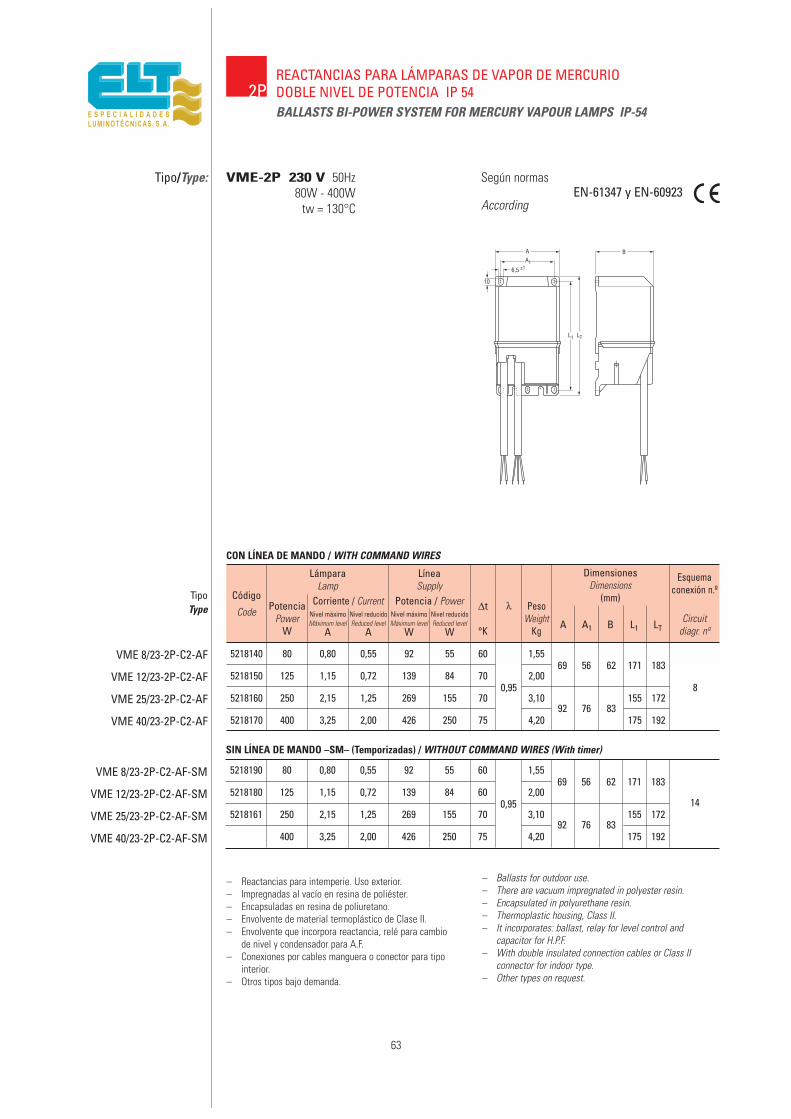
5218140 80 0,80 0,55 92 55 60 1,5569 56 62 171 183
5218150 125 1,15 0,72 139 84 700,95
2,008
5218160 250 2,15 1,25 269 155 70 3,10 155 172
5218170 400 3,25 2,00 426 250 75 4,2092 76 83
175 192
– Reactancias para intemperie. Uso exterior.– Impregnadas al vacío en resina de poliéster.– Encapsuladas en resina de poliuretano.– Envolvente de material termoplástico de Clase II.– Envolvente que incorpora reactancia, relé para cambio
de nivel y condensador para A.F.– Conexiones por cables manguera o conector para tipo
interior.– Otros tipos bajo demanda.
– Ballasts for outdoor use.– There are vacuum impregnated in polyester resin.– Encapsulated in polyurethane resin.– Thermoplastic housing, Class II.– It incorporates: ballast, relay for level control and
capacitor for H.P.F.– With double insulated connection cables or Class II
connector for indoor type.– Other types on request.
63
2PREACTANCIAS PARA LÁMPARAS DE VAPOR DE MERCURIODOBLE NIVEL DE POTENCIA IP 54BALLASTS BI-POWER SYSTEM FOR MERCURY VAPOUR LAMPS IP-54
Tipo/Type: Según normas
AccordingEN-61347 y EN-60923
VME-2P 230 V 50Hz80W - 400W
tw = 130°C
Código
Code
TipoType
VME 8/23-2P-C2-AF
VME 12/23-2P-C2-AF
VME 25/23-2P-C2-AF
VME 40/23-2P-C2-AF
LámparaLamp
PotenciaPower
W
Corriente / CurrentNivel máximoMáximum level
A
Nivel reducidoReduced level
A
Nivel máximoMáximum level
W
Nivel reducidoReduced level
W
Potencia / Power
LíneaSupply
∆t
°K
λ PesoWeight
KgCircuit
diagr. nº
Esquemaconexión n.º
DimensionesDimensions
(mm)
CON LÍNEA DE MANDO / WITH COMMAND WIRES
A A1 B L1 LT
5218190 80 0,80 0,55 92 55 60 1,5569 56 62 171 183
5218180 125 1,15 0,72 139 84 600,95
2,00
5218161 250 2,15 1,25 269 155 70 3,10 155 17214
400 3,25 2,00 426 250 75 4,2092 76 83
175 192
VME 8/23-2P-C2-AF-SM
VME 12/23-2P-C2-AF-SM
VME 25/23-2P-C2-AF-SM
VME 40/23-2P-C2-AF-SM
SIN LÍNEA DE MANDO –SM– (Temporizadas) / WITHOUT COMMAND WIRES (With timer)
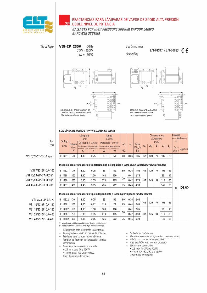
6114622 70 1,00 0,75 83 50 60 0,36 2,0062 120 77 105 126
6114581 100 1,20 0,92 116 72 65 0,44 2,05
6114982 150 1,80 1,30 168 10070
0,41 2,85 96 115
6114561 250 3,00 2,35 278 165 0,42 3,90 87 145 91 116 135
6114692 400 4,45 3,65 435 262 75 0,45 5,20 145 165
6114621 70 1,00 0,75 83 50 60 0,36 1,90 62 120 77 105 126
6114981 150 1,80 1,30 168 10070
0,41 2,75 96 115
6114961 250 3,00 2,35 278 165 0,42 3,70 87 145 91 116 135
6114971 400 4,45 3,65 435 262 75 0,45 4,98 145 165
6114611 70 1,00 0,75 83 50 60 0,36 1,85 62 120 77 105 126
64
2PREACTANCIAS PARA LÁMPARAS DE VAPOR DE SODIO ALTA PRESIÓNDOBLE NIVEL DE POTENCIABALLASTS FOR HIGH PRESSURE SODIUM VAPOUR LAMPSBI-POWER SYSTEM
Tipo/Type: Según normas
AccordingEN-61347 y EN-60923
– Reactancias para incorporar. Uso interior.– Impregnadas al vacío en resina de poliéster.– Previstas para compensación adicional.– También se fabrican con protección térmica
incorporada.– Con clema de conexión por tornillo
• 2,5 mm2 para 70 y 100W.• 4 mm2 para 150, 250 y 400W.
– Otros tipos bajo demanda.
– Ballasts for built-in use.– There are vacuum impregnated in polyester resin.– Additional compensation provided.– Also available with thermal protector.– With screw connection
• 2,5 mm2 for 70 and 100W.• 4 mm2 for 150, 250 and 400W.
– Other types on request.
VSI-2P 230V 50Hz70W - 400W
tw = 130°C
TipoType
VSI 7/23-2P-2-CA s/arr.
VSI 7/23-2P-CA-100
VSI 15/23-2P-CA-003 (*)
VSI 25/23-2P-CA-003 (*)
VSI 40/23-2P-CA-003 (*)
CON LÍNEA DE MANDO / WITH COMMAND WIRES
VSI 7/23-2P-CA-70
VSI 10/23-2P-CA-150
VSI 15/23-2P-CA-150
VSI 25/23-2P-CA-400
VSI 40/23-2P-CA-400(*) Modelos no válidos para lámpara de alto rendimiento.(*) Not suitable for use with HPS High efficiency lamps.
Código
Code
LámparaLamp
PotenciaPower
W
Corriente / CurrentNivel máximoMáximum level
A
Nivel reducidoReduced level
A
Nivel máximoMáximum level
W
Nivel reducidoReduced level
W
Potencia / Power
LíneaSupply
∆t
°K
λ PesoWeight
Kg
A1 A2 B L1 L2 Circuitdiagr. nº Approvals
Esquemaconexión
n.ºHomolog.
DimensionesDimensions
(mm)
12
Modelos con arrancador de transformación de impulsos / With pulse-transformer ignitor models
Modelos con arrancador de tipo independiente / With superimposed ignitor models
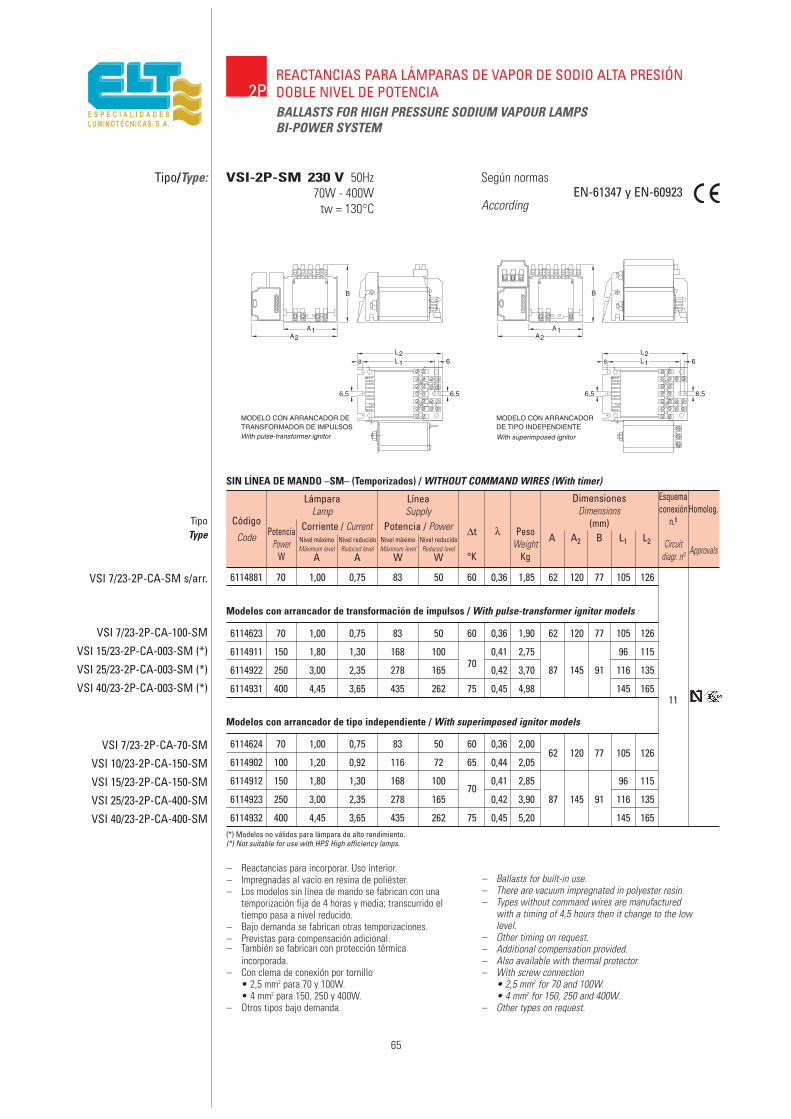
6114881 70 1,00 0,75 83 50 60 0,36 1,85 62 120 77 105 126
65
2PREACTANCIAS PARA LÁMPARAS DE VAPOR DE SODIO ALTA PRESIÓNDOBLE NIVEL DE POTENCIABALLASTS FOR HIGH PRESSURE SODIUM VAPOUR LAMPSBI-POWER SYSTEM
Tipo/Type: Según normas
AccordingEN-61347 y EN-60923
– Reactancias para incorporar. Uso interior.– Impregnadas al vacío en resina de poliéster.– Los modelos sin línea de mando se fabrican con una
temporización fija de 4 horas y media; transcurrido eltiempo pasa a nivel reducido.
– Bajo demanda se fabrican otras temporizaciones.– Previstas para compensación adicional.– También se fabrican con protección térmica
incorporada.– Con clema de conexión por tornillo
• 2,5 mm2 para 70 y 100W.• 4 mm2 para 150, 250 y 400W.
– Otros tipos bajo demanda.
– Ballasts for built-in use.– There are vacuum impregnated in polyester resin.– Types without command wires are manufactured
with a timing of 4,5 hours then it change to the lowlevel.
– Other timing on request.– Additional compensation provided.– Also available with thermal protector.– With screw connection
• 2,5 mm2 for 70 and 100W.• 4 mm2 for 150, 250 and 400W.
– Other types on request.
VSI-2P-SM 230 V 50Hz70W - 400W
tw = 130°C
TipoType
VSI 7/23-2P-CA-SM s/arr.
VSI 7/23-2P-CA-100-SM
VSI 15/23-2P-CA-003-SM (*)
VSI 25/23-2P-CA-003-SM (*)
VSI 40/23-2P-CA-003-SM (*)
6114623 70 1,00 0,75 83 50 60 0,36 1,90 62 120 77 105 126
6114911 150 1,80 1,30 168 10070
0,41 2,75 96 115
6114922 250 3,00 2,35 278 165 0,42 3,70 87 145 91 116 135
6114931 400 4,45 3,65 435 262 75 0,45 4,98 145 165
SIN LÍNEA DE MANDO –SM– (Temporizados) / WITHOUT COMMAND WIRES (With timer)
Modelos con arrancador de transformación de impulsos / With pulse-transformer ignitor models
VSI 7/23-2P-CA-70-SM
VSI 10/23-2P-CA-150-SM
VSI 15/23-2P-CA-150-SM
VSI 25/23-2P-CA-400-SM
VSI 40/23-2P-CA-400-SM
6114624 70 1,00 0,75 83 50 60 0,36 2,0062 120 77 105 126
6114902 100 1,20 0,92 116 72 65 0,44 2,05
6114912 150 1,80 1,30 168 10070
0,41 2,85 96 115
6114923 250 3,00 2,35 278 165 0,42 3,90 87 145 91 116 135
6114932 400 4,45 3,65 435 262 75 0,45 5,20 145 165(*) Modelos no válidos para lámpara de alto rendimiento.(*) Not suitable for use with HPS High efficiency lamps.
11
Modelos con arrancador de tipo independiente / With superimposed ignitor models
Código
Code
LámparaLamp
PotenciaPower
W
Corriente / CurrentNivel máximoMáximum level
A
Nivel reducidoReduced level
A
Nivel máximoMáximum level
W
Nivel reducidoReduced level
W
Potencia / Power
LíneaSupply
∆t
°K
λ PesoWeight
Kg
A A2 B L1 L2 Circuitdiagr. nº Approvals
Esquemaconexión
n.ºHomolog.
DimensionesDimensions
(mm)

6218201 70 1,00 0,75 83 50 60 2,35 69 56 62 171 183
6218210 100 1,20 0,92 116 72 3,10 155 172
6218220 150 1,80 1,30 168 100 70 0,90 3,50 155 172
6218230 250 3,00 2,35 278 165 4,4392 76 83
175 192
6218240 400 4,45 3,65 435 262 75 5,67 205 222
6218200 70 1,00 0,75 83 50 70 0,90 2,10 69 56 62 171 183 8
66
2PREACTANCIAS PARA LÁMPARAS DE VAPOR DE SODIO ALTA PRESIÓNDOBLE NIVEL DE POTENCIA IP-54BALLASTS FOR HIGH PRESSURE SODIUM VAPOUR LAMPSBI-POWER SYSTEM IP-54
Tipo/Type: Según normas
AccordingEN-61347 y EN-60923
– Reactancias para intemperie. Uso exterior.– Impregnadas al vacío en resina de poliéster.– Encapsuladas en resina de poliuretano.– Envolvente de material temoplástico Clase II.– Incluye reactancia, arrancador, condensador
y relé para cambio de nivel.– Conexiones por cables manguera o conector
para tipo interior.– Otros tipos bajo demanda.
– Ballasts for outdoor use.– There are vacuum impregnated in polyester resin.– Encapsulated in polyurethane resin.– Thermoplastic housing, Class II.– This gear includes: ballast, ignitor, capacitor and
relay to change the level.– Connections by double insulated cables.– Other types on request.
VSE-2P 230V 50Hz70W - 400W
tw = 130°C
Código
Code
TipoType
VSE 7/23-2P-C2-AF s/arr.
LámparaLamp
PotenciaPower
W
Corriente / CurrentNivel máximoMáximum level
A
Nivel reducidoReduced level
A
Nivel máximoMáximum level
W
Nivel reducidoReduced level
W
Potencia / Power
LíneaSupply
∆t
°K
λ PesoWeight
KgCircuit
diagr. nº
8
Esquemaconexión n.º
VSE 7/23-2P-C2-AF
VSE 10/23-2P-C2-AF
VSE 15/23-2P-C2-AF (*)
VSE 25/23-2P-C2-AF (*)
VSE 40/23-2P-C2-AF (*)
Modelos con arrancador de transformación de impulsos / With pulse-transformer ignitor models
DimensionesDimensions
(mm)
A A1 B L1 LT
6218250 70 1,00 0,75 83 50 60 2,35 69 56 62 171 183
6218211 100 1,20 0,92 116 72 3,10 155 172
6218221 150 1,80 1,30 168 100 70 0,90 3,50 155 172
250 3,00 2,35 278 165 4,4392 76 83
175 192
400 4,45 3,65 435 262 75 5,67 205 222
70 1,00 0,75 83 50 70 0,90 2,10 69 56 62 171 183 14VSE 7/23-2P-C2-AF-SM s/arr.
14
VSE 7/23-2P-C2-AF-SM
VSE 10/23-2P-C2-AF-SM
VSE 15/23-2P-C2-AF-SM (*)
VSE 25/23-2P-C2-AF-SM (*)
VSE 40/23-2P-C2-AF-SM (*)
Modelos con arrancador de transformación de impulsos / With pulse-transformer ignitor models
CON LÍNEA DE MANDO / WITH COMMAND WIRES
(*) Modelos no válidos para lámpara de alto rendimiento. (Para estas lámparas, solicitar las reactancias con arrancador independiente).(*) Not suitable for use with HPS high efficiency lamps. (Ask in such case for ballasts with superimposed ignitor).
SIN LÍNEA DE MANDO / WITHOUT COMMAND WIRES
67
REACTANCIAS DE CLASE IIBALLASTS CLASS II
CII

68
Ballasts for discharge lamps.
Class II
DEFINITION
Ballasts with complete integrated equipment: Ballast, starter,p. f. corrector capacitor and connector for line and lamp, class II.
All the parts are protected with an insulating casing whichensures the impossibility of contact with active parts or which
can become active due to a fault in the main insulation.
Which defines them as insulation safety against electricchokes class II.
They do not require earth connection.
USES
In installations where extreme safety is required against electricchokes in order to guarantee the safety of the people, animals or
goods. In short, class II installations.
Also ideal for public lighting installations where due to earthbypasses which exist in the equipment, the protection differentials
are activated frequently, cutting off the electricity, forcing theequipment (ballast, starter and capacitor) to be fitted to insulating
plates to prevent currents leaking to earth. Its total externalinsulating protection prevents these currents without the need for
additional insulating elements.
INSTALLATION
For interior use request types VSI.../23-CS-AD or AI.
They must be installed by securing them inside the light fittings orhanging on the inside of the columns by at least two of their
fastening holes.
For use on the inside of light fittings they can be supplied in“Compact assembly” format in type VSI.../23-CS-AI or in
“Interconnected sub-assembly” format types VSI.../23-C2S-AIwhich can be fitted in more reduced spaces if the compact
assembly does not allow this.
They must not be installed outdoors as an independent ballast, asthey require additional protection against water.
For their use, use ballasts type VSE.../23-C2-AIwhich, made with the same insulating casing, have connection
outlets with hoses and which installed in vertical position (wiresdownwards), reach a protection degree of IP-54.
Foresee the capacity of the wire from the ballast to the lampto request them with dependent ignitor (AD) or independent
ignitor (AI)
Balastos para lámparas de descarga.
Clase II
DEFINICIÓN
Balastos con equipo completo integrado: Reactancia, arrancador,condensador de corrección del f. de p. y conector para línea ylámpara, clase II.
Todas sus partes están protegidas con un envolvente aislante queasegura la imposibilidad de contacto con partes activas o que puedanconvertirse en activas por un fallo del aislamiento principal.
Lo que las define como seguridad de aislamiento contra choqueseléctricos clase II.
No necesitan de conexión a tierra.
USOS
En instalaciones donde se desee una seguridad extrema contrachoques eléctricos para garantizar la seguridad de las personas,animales o bienes. En definitiva, instalaciones de clase II.
Igualmente idóneas para instalaciones de alumbrado público donde,por derivaciones a tierra existentes en los equipos, se activan confrecuencia los diferenciales de protección, cortando el servicioeléctrico. Lo que obliga a fijar los equipos (reactancia, arrancador ycondensador) sobre placas aislantes que evite las corrientes de fugaa tierra. Su total protección aislante externa evita tales corrientes sinnecesidad de elementos aislantes adicionales.
INSTALACIÓN
Para uso interior solicitar los tipos VSI.../23-C2-AD o AI.
Su instalación debe ser realizada fijándolos en el interior deluminarias o colgados en el interior de los báculos por al menos dosde sus agujeros de fijación.
Para el uso en el interior de luminarias se pueden suministrar enformato “Conjunto compacto” en el tipo VSI.../23-C2-AI o en elformato “Subconjuntos interconectados” tipos VSI.../23-C2S-AI, quepermiten ser fijados en espacios más reducidos si el conjuntocompacto no lo permite.
No deben instalarse a la intemperie como reactancia independiente,pues requieren de una protección adicional contra la caída de agua.
Para uso intemperie utilizar los balastos del tipo VSE.../23-C2-AIque construidos con el mismo envolvente aislante, llevan salidas deconexión con cables manguera, y que instalados en posición vertical(cables hacia abajo) alcanzan un grado de protección IP-54.
Prever la capacidad del cable desde el balasto a la lámpara parasolicitarlas con arrancador dependiente (AD) o arrancadorindependiente (AI).

69
INPUT AND LAMP CONNECTION
For indoor use
The ballast has a protected class II connector which is securedto the casing by means of a coupling flange which prevents
accidental disconnection.
To disconnect, press the grooved button and pull the connectoroutwards.
The connection is made so that when withdrawingthe setscrews from the cover, the “input” and “lamp” terminals
appear, to be used according to figure.
For outdoor use
By means of 0.6/1kV wires identified by their position,one for INPUT and another for LAMP.
Never work on the ballast unless the service voltage has beenwithdrawn.
TECHNICAL AND CONSTRUCTIVE CHARACTERISTICS
– Windings in thermal class 200° C.
– Vacuum-impregnated in irreversible polymerisation resincarried out at 150° C.
– Internal encapsulation with polyurethane resin.
– Insulating casing in 6.6. polyamide with 30% fibreglass,pigmented in grey as protection against UV rays.
– They include: ballast, starter, p.f. correction capacitor andclass II connector for input and lamp.
– Operating ambient temperatures –25° C a +60° C (max. ta = 60° C).
CONEXIÓN LÍNEA Y LÁMPARA
Para uso interior
El balasto lleva un conector protegido de clase II, que queda sujetoal envolvente mediante una uña de enganche que impide unadesconexión fortuita.
Para desconectarlo, presionar el botón rayado y tirar del conectorhacia fuera.
La conexión se realiza de forma que al retirar los tornillos de fijaciónde la tapa-cubierta aparecen los bornes de “línea” y “lamp.” para serutilizados según figura.
Para uso exterior
Mediante cables de 0,6/1kV identificados por su posicionamiento,uno para LÍNEA y otro para LÁMPARA.
No operar nunca en el balasto sin retirar la tensión de servicio.
CARACTERÍSTICAS TÉCNICAS Y CONSTRUCTIVAS
– Bobinadas en clase térmica 200° C.
– Impregnadas al vacío en resina de polimerización irreversible,realizada a 150° C.
– Encapsulado interno con resina de poliuretano.
– Envolvente aislante en poliamida 6.6 con 30% de fibra de vidrio,pigmentada en gris como protección contra los rayos U.V.
– Llevan incorporados: reactancia, arrancador, condensador decorrección del f. de p. y conector Clase II para línea y lámpara.
– Temperaturas ambiente de funcionamiento –25° C a +60° C(ta máx. = 60° C).
F N
N
F
LÍNEAINPUT
LÍNEAINPUT
LÁMPARALAMP
LÁMP.LAMP
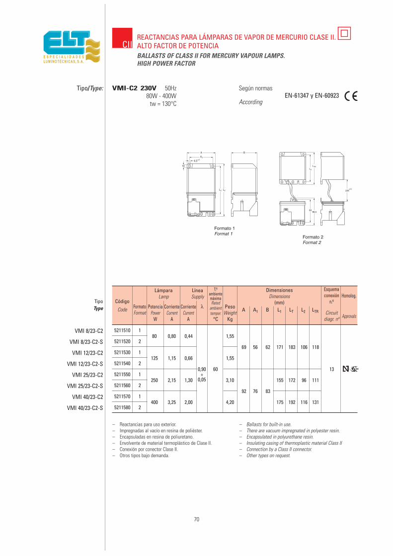
5211510 180 0,80 0,44 1,55
5211520 269 56 62 171 183 106 118
5211530 1125 1,15 0,66 1,55
5211540 20,90 60 13
5211550 1250 2,15 1,30
+3,10 155 172 96 111
5211560 20,05
92 76 835211570 1
400 3,25 2,00 4,20 175 192 116 1315211580 2
70
REACTANCIAS PARA LÁMPARAS DE VAPOR DE MERCURIO CLASE II.ALTO FACTOR DE POTENCIABALLASTS OF CLASS II FOR MERCURY VAPOUR LAMPS.HIGH POWER FACTOR
Según normas
AccordingEN-61347 y EN-60923
– Reactancias para uso exterior.– Impregnadas al vacío en resina de poliéster.– Encapsuladas en resina de poliuretano.– Envolvente de material termoplástico de Clase II.– Conexión por conector Clase II.– Otros tipos bajo demanda.
– Ballasts for built-in use.– There are vacuum impregnated in polyester resin.– Encapsulated in polyurethane resin.– Insulating casing of thermoplastic material Class II– Connection by a Class II connector.– Other types on request.
Código
Code
TipoType
VMI 8/23-C2
VMI 8/23-C2-S
VMI 12/23-C2
VMI 12/23-C2-S
VMI 25/23-C2
VMI 25/23-C2-S
VMI 40/23-C2
VMI 40/23-C2-S
LámparaLamp
PotenciaPower
W
CorrienteCurrent
A
LíneaSupply
CorrienteCurrent
A
λ PesoWeight
Kg°C
T.ªambientemáximaRated
ambienttemper.
FormatoFormat A A1 B L1 LT L2 LTR Circuit
diagr. nº
Esquemaconexión
n.º
DimensionesDimensions
(mm)
VMI-C2 230V 50Hz80W - 400W
tw = 130°C
Approvals
Homolog.
Formato 1Format 1
Formato 2Format 2
CII
Tipo/Type:
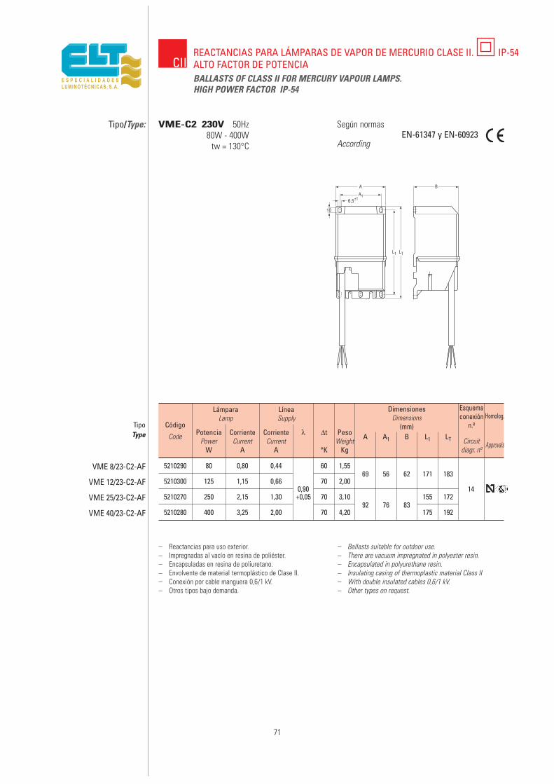
5210290 80 0,80 0,44 60 1,5569 56 62 171 183
5210300 125 1,15 0,660,90
70 2,0014
5210270 250 2,15 1,30 +0,05 70 3,1092 76 83
155 172
5210280 400 3,25 2,00 70 4,20 175 192
71
CIIREACTANCIAS PARA LÁMPARAS DE VAPOR DE MERCURIO CLASE II. IP-54ALTO FACTOR DE POTENCIABALLASTS OF CLASS II FOR MERCURY VAPOUR LAMPS.HIGH POWER FACTOR IP-54
Tipo/Type: Según normas
AccordingEN-61347 y EN-60923
– Reactancias para uso exterior.– Impregnadas al vacío en resina de poliéster.– Encapsuladas en resina de poliuretano.– Envolvente de material termoplástico de Clase II.– Conexión por cable manguera 0,6/1 kV.– Otros tipos bajo demanda.
– Ballasts suitable for outdoor use.– There are vacuum impregnated in polyester resin.– Encapsulated in polyurethane resin.– Insulating casing of thermoplastic material Class II– With double insulated cables 0,6/1 kV.– Other types on request.
Código
Code
TipoType
VME 8/23-C2-AF
VME 12/23-C2-AF
VME 25/23-C2-AF
VME 40/23-C2-AF
LámparaLamp
PotenciaPower
W
CorrienteCurrent
A
LíneaSupply
CorrienteCurrent
A
λ PesoWeight
Kg
∆t
°K
A A1 B L1 LT Circuitdiagr. nº
Esquemaconexión
n.º
DimensionesDimensions
(mm)
VME-C2 230V 50Hz80W - 400W
tw = 130°C
Approvals
Homolog.
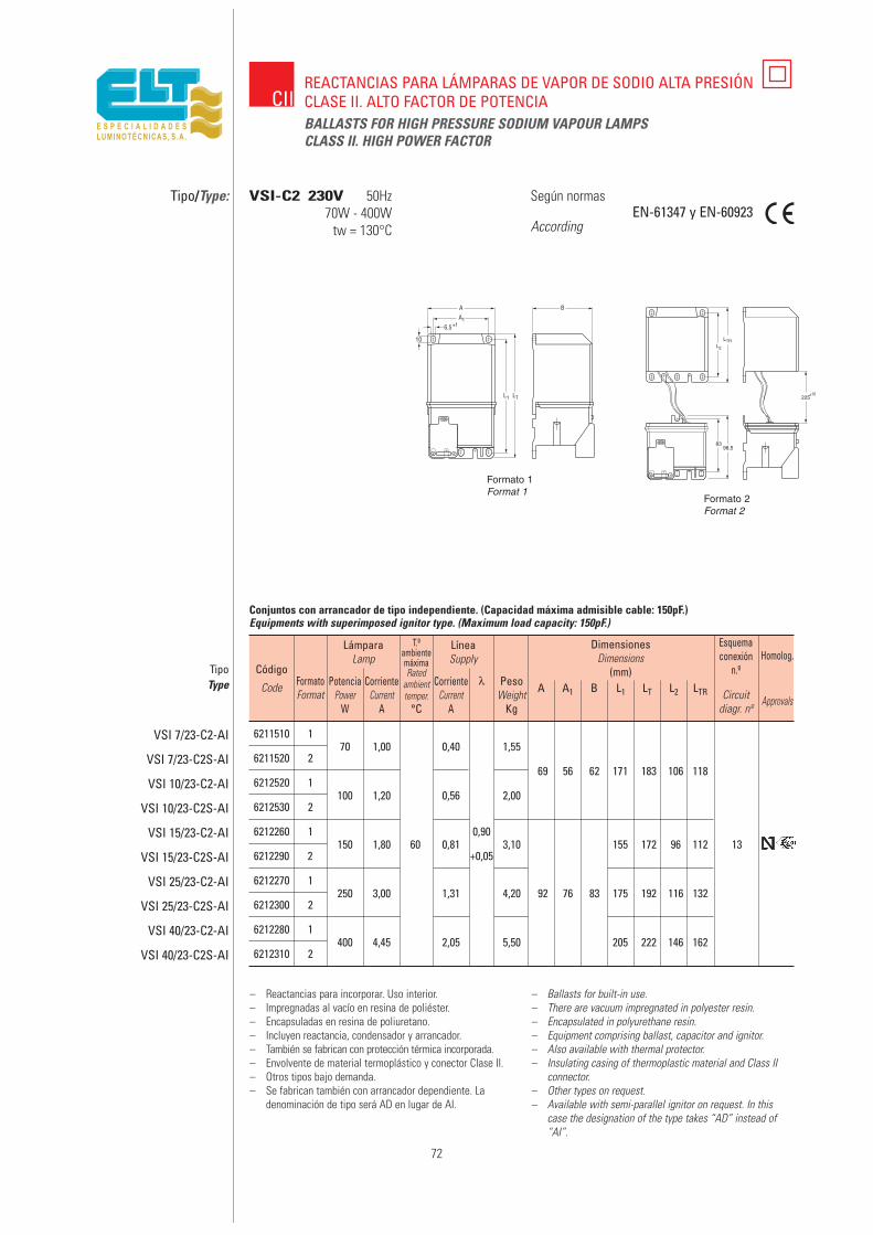
6211510 170 1,00 0,40 1,55
6211520 269 56 62 171 183 106 118
6212520 1100 1,20 0,56 2,00
6212530 2
6212260 1150 1,80 60 0,81
0,903,10 155 172 96 112 13
6212290 2 +0,05
6212270 1250 3,00 1,31 4,20 92 76 83 175 192 116 132
6212300 2
6212280 1400 4,45 2,05 5,50 205 222 146 162
6212310 2
72
CIIREACTANCIAS PARA LÁMPARAS DE VAPOR DE SODIO ALTA PRESIÓNCLASE II. ALTO FACTOR DE POTENCIABALLASTS FOR HIGH PRESSURE SODIUM VAPOUR LAMPSCLASS II. HIGH POWER FACTOR
Tipo/Type: Según normas
AccordingEN-61347 y EN-60923
– Reactancias para incorporar. Uso interior.– Impregnadas al vacío en resina de poliéster.– Encapsuladas en resina de poliuretano.– Incluyen reactancia, condensador y arrancador.– También se fabrican con protección térmica incorporada.– Envolvente de material termoplástico y conector Clase II.– Otros tipos bajo demanda.– Se fabrican también con arrancador dependiente. La
denominación de tipo será AD en lugar de AI.
– Ballasts for built-in use.– There are vacuum impregnated in polyester resin.– Encapsulated in polyurethane resin.– Equipment comprising ballast, capacitor and ignitor.– Also available with thermal protector.– Insulating casing of thermoplastic material and Class II
connector.– Other types on request.– Available with semi-parallel ignitor on request. In this
case the designation of the type takes “AD” instead of“AI”.
Código
Code
TipoType
VSI 7/23-C2-AI
VSI 7/23-C2S-AI
VSI 10/23-C2-AI
VSI 10/23-C2S-AI
VSI 15/23-C2-AI
VSI 15/23-C2S-AI
VSI 25/23-C2-AI
VSI 25/23-C2S-AI
VSI 40/23-C2-AI
VSI 40/23-C2S-AI
LámparaLamp
PotenciaPower
W
CorrienteCurrent
A
LíneaSupply
CorrienteCurrent
A
λ PesoWeight
Kg°C
T.ªambientemáximaRated
ambienttemper.
FormatoFormat A A1 B L1 LT L2 LTR Circuit
diagr. nº
Esquemaconexión
n.º
DimensionesDimensions
(mm)
VSI-C2 230V 50Hz70W - 400W
tw = 130°C
Conjuntos con arrancador de tipo independiente. (Capacidad máxima admisible cable: 150pF.)Equipments with superimposed ignitor type. (Maximum load capacity: 150pF.)
Approvals
Homolog.
Formato 1Format 1
Formato 2Format 2
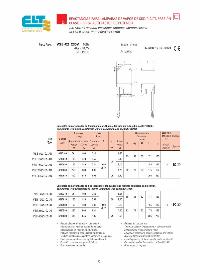
73
Tipo/Type: Según normas
AccordingEN-61347 y EN-60923
– Reactancias para intemperie. Uso exterior.– Impregnadas al vacío en resina de poliéster.– Encapsuladas en resina de poliuretano.– Incluyen reactancia, condensador y arrancador.– También se fabrican con protección térmica incorporada.– Envolvente de material termoplástico de Clase II.– Conexión por cable manguera 0,6/1 kV.– Otros tipos bajo demanda.
– Ballasts for outdoor use.– There are vacuum impregnated in polyester resin.– Encapsulated in polyurethane resin.– Equipment comprising ballast, capacitor and ignitor.– Also available with thermal protector.– Insulating casing of thermoplastic material Class II.– Connection by double insulated cables 0,6/1 kV.– Other types on request.
VSE-C2 230V 50Hz70W - 400W
tw = 130°C
BALLASTS FOR HIGH PRESSURE SODIUM VAPOUR LAMPSCLASS II IP-54. HIGH POWER FACTOR
CIIREACTANCIAS PARA LÁMPARAS DE VAPOR DE SODIO ALTA PRESIÓNCLASE II IP-54. ALTO FACTOR DE POTENCIA
6210160 70 1,00 0,40 1,5569 56 62 171 183
6210640 100 1,20 0,55 2,00
6210650 150 1,80 0,81 0,9070
3,10 155 172 14
6210660 250 3,00 1,31+0,05
4,20 92 76 83 175 192
6210670 400 4,45 2,05 75 5,50 205 222
Código
Code
TipoType
VSE 7/23-C2-AD
VSE 10/23-C2-AD
VSE 15/23-C2-AD
VSE 25/23-C2-AD
VSE 40/23-C2-AD
LámparaLamp
PotenciaPower
W
CorrienteCurrent
A
LíneaSupply
CorrienteCurrent
A
λ PesoWeight
Kg
∆t
°K
A A1 B L1 LT Circuitdiagr. nº
Esquemaconexión
n.º
DimensionesDimensions
(mm)
Conjuntos con arrancador de transformación. (Capacidad máxima admisible cable: 1000pF.)Equipments with pulse transformer ignitor. (Maximum load capacity: 1000pF.)
6210310 70 1,00 0,40 1,5569 56 62 171 183
6210610 100 1,20 0,55 70 2,00
6210580 150 1,80 0,81 0,90 3,10 155 172 14
6210590 250 3,00 1,31+0,05
4,20 92 76 83 175 192
6210600 400 4,45 2,05 75 5,50 205 222
VSE 7/23-C2-AI
VSE 10/23-C2-AI
VSE 15/23-C2-AI
VSE 25/23-C2-AI
VSE 40/23-C2-AI
Conjuntos con arrancador de tipo independiente. (Capacidad máxima admisible cable: 150pF.)Equipments with superimposed ignitor. (Maximum load capacity: 150pF.)
Approvals
Homolog.

6211510 170 1,00 0,40 1,55
6211520 269 56 62 171 183 106 118
6212520 1100 1,20 0,55 2,00
6212530 2
6212260 1150 1,80 0,81 3,10
6212290 2155 172 96 112
6212320 12,20 1,30 3,10 13
6212330 2250
60 0,90
6212270 13,00 1,31
+0,05
4,206212300 2
92 76 83
175 192 116 1326212340 1
3,50 2,00 4,206212350 2
4006212280 1
4,20 2,05 5,506212310 2
205 222 146 162
74
CIIREACTANCIAS PARA LÁMPARAS DE HALOGENUROS METÁLICOSCLASE II. ALTO FACTOR DE POTENCIABALLASTS FOR METAL HALIDE LAMPS CLASS II.HIGH POWER FACTOR
Tipo/Type: Según normas
AccordingEN-61347 y EN-60923
– Reactancias para incorporar. Uso interior.– Impregnadas al vacío en resina de poliéster.– Encapsuladas en resina de poliuretano.– Incluyen reactancia, condensador y arrancador (tipo inde-
pendiente-AI).– También se fabrican con protección térmica incorporada.– Envolvente de material termoplástico y conector Clase II.– Otros tipos bajo demanda.
– Ballasts for built-in use.– There are vacuum impregnated in polyester resin.– Encapsulated in polyurethane resin.– Equipment comprising ballast, capacitor and ignitor.– Also available with thermal protector.– Insulating casing of thermoplastic material and Class II
connector.– Other types on the request.
Código
Code
TipoType
VSI 7/23-C2-AI
VSI 7/23-C2S-AI
VSI 10/23-C2-AI
VSI 10/23-C2S-AI
VSI 15/23-C2-AI
VSI 15/23-C2S-AI
VHI 25/23-C2-AI
VHI 25/23-C2S-AI
VSI 25/23-C2-AI
VSI 25/23-C2S-AI
VHI 40/23-C2-AI
VHI 40/23-C2S-AI
VSI 40/23-C2-AI
VSI 40/23-C2S-AI
LámparaLamp
PotenciaPower
W
CorrienteCurrent
A
LíneaSupply
CorrienteCurrent
A
λ PesoWeight
Kg°C
T.ªambientemáximaRated
ambienttemper.
FormatoFormat A A1 B L1 LT L2 LTR Circuit
diagr. nº
Esquemaconexión
n.º
DimensionesDimensions
(mm)
VHI-C2 230V 50Hz70W - 400W
tw = 130°C
Conjuntos con arrancador de tipo independiente. (Capacidad máxima admisible cable: 150pF.)Equipments with superimposed ignitor. (Máximum load capacity: 150pF.)
Approvals
Homolog.
Formato 1Format 1 Formato 2
Format 2
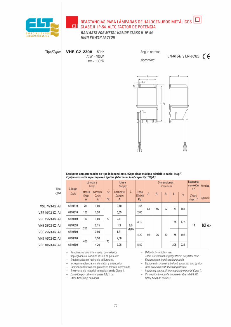
6210310 70 1,00 0,40 1,5569 56 62 171 183
6210610 100 1,20 0,55 2,00
6210580 150 1,80 70 0,813,10 155 172
6210620250
2,15 1,3 0,9 14
6210590 3,00 1,31+0,05
4,20 92 76 83 175 1926210680
4003,50
752,00
6210600 4,20 2,05 5,50 205 222
75
Tipo/Type: Según normas
AccordingEN-61347 y EN-60923
– Reactancias para intemperie. Uso exterior.– Impregnadas al vacío en resina de poliéster.– Encapsuladas en resina de poliuretano.– Incluyen reactancia, condensador y arrancador.– También se fabrican con protección térmica incorporada.– Envolvente de material termoplástico de Clase II.– Conexión por cable manguera 0,6/1 kV.– Otros tipos bajo demanda.
– Ballasts for outdoor use.– There are vacuum impregnated in polyester resin.– Encapsulated in polyurethane resin.– Equipment comprising ballast, capacitor and ignitor.– Also available with thermal protector.– Insulating casing of thermoplastic material Class II.– Connection by double insulated cables 0,6/1 kV.– Other types on request.
VHE-C2 230V 50Hz70W - 400W
tw = 130°C
BALLASTS FOR METAL HALIDE CLASS II IP-54.HIGH POWER FACTOR
CIIREACTANCIAS PARA LÁMPARAS DE HALOGENUROS METÁLICOSCLASE II IP-54. ALTO FACTOR DE POTENCIA
Código
Code
TipoType
VSE 7/23-C2-AI
VSE 10/23-C2-AI
VSE 15/23-C2-AI
VHE 25/23-C2-AI
VSE 25/23-C2-AI
VHE 40/23-C2-AI
VSE 40/23-C2-AI
LámparaLamp
PotenciaPower
W
CorrienteCurrent
A
LíneaSupply
CorrienteCurrent
A
λ PesoWeight
Kg
∆t
°K
A A1 B L1 LT Circuitdiagr. nº
Esquemaconexión
n.º
DimensionesDimensions
Conjuntos con arrancador de tipo independiente. (Capacidad máxima admisible cable: 150pF.)Equipments with superimposed ignitor. (Maximum load capacity: 150pF.)
Approvals
Homolog.
76

77
REACTANCIAS AUTORREGULADASCONSTANT WATTAGE AUTOTRANSFOMER BALLASTS
VSRI

78
Constant wattage autotransformer-type(CWA) ballast
For High Pressure Sodium LampsDEFINITION
Ballast for HP sodium lamps, consisting of a constant wattageautotransformer (CWA) ballast, with a starter and a series
capacitor for stabilising the current in the lamp and correcting thepower factor.
As its name indicates (CWA - Constant Wattage Autotransformer),they are used to maintain good power regulation on the lamp
when faced with power grid variations.– They meet the trapeze limits in accordance with CEI 662.
– They increase the life of the lamp due to they keep its powerbetween very narrow limits.
– Necessary in installations with power supply voltages below198V.
– Manufactured for voltages from 110 to 277V and withfrequencies of 50 or 60 Hz.
– They are ballasts to “be installed”.
USES– They are supplied for use in installations with power supply
voltages below 198V (i.e.: 110, 120, 150V…), the minimum voltagethat the lamp needs for stable operation.
– Likewise valid for installations with strong variations in thepower supply voltage (exceeding ± 10% of the nominal value) in
order to avoiding shortening the life of the lamps.
INSTALLATION– They must be installed in the interior of lighting fixtures, boxes
or housings that protect them against atmospheric agents.– With an independent ignitor starter (AI), they must be installed
close to the lamp (no more than 2 metres).– The cables from the ballast to the lamp must be laid out to
support the high voltage impulses (3–5KV) that the starterganerates for starting the lamp.
– In order to ensure correct operation and a long life of thecomponents (autotransformer, starter and capacitor), verify that
under normal operation the tw and tc temperature limit values ofeach component are not exceeded, which values are indicated by
their respective markings.– As a protective measure, connect the metal parts of the
autotransformer to an earth ground.
TECHNICAL AND CONSTRUCTION CHARACTERISTICS– PA 6.6 polyamide coil support (with 30% fibreglass).
– Cu wire coils, 2000C thermal class.– Vacuum impregnated at 1500C with white, irreversible
polymerisation resin.– Consisting of a constant wattage autotransformer (CWA), starter
and capacitor.– Maximum temperatures on the coils, tw=1300C; on the
independent starter, 1050C; and on the capacitor, 85CC.
Reactancias autorreguladas para lámparasde descarga de Vapor de Sodio Alta Presión(CWA)DEFINICIÓNBalasto para lámparas de sodio A.P., compuesto de reactanciaautotransformador de vataje constante (CWA) con arrancadorindependiente y condensador en serie, para estabilizar la corriente de lalámpara y corregir el factor de potencia.Como su denominación indica (CWA Autotransformador de VatajeConstante), sirven para mantener una buena regulación de potencia enla lámpara, frente a las variaciones de la tensión de la red.– Cumplen los límites del trapecio según CEI 662.– Aumentan la vida de la lámpara debido a que mantienen su potencia
dentro de márgenes muy estrechos.– Necesarias en instalaciones con tensiones de alimentación inferiores
a 198V.– Se fabrican para tensiones desde 110 a 277V y frecuencias de 50 ó 60Hz.– Son balastos “a incorporar”.
USOS– Están previstas para usos en instalaciones con tensiones de
alimentación inferiores a 198V (ej. 110, 120, 150V…), tensión mínimaque la lámpara necesita para un funcionamiento estable.
– Igualmente válidas para instalaciones con fuertes variaciones de latensión de alimentación (que superen el ±10% del valor nominal) paraevitar el acortamiento de la vida de las lámparas.
INSTALACIÓN– Su instalación debe ser realizada en el interior de luminarias, cajas o
cofres de protección contra los agentes atmosféricos.– Con arrancador de tipo independiente, deben instalarse próxima a la
lámpara (no más de 2 m.).– Los cables desde el balasto a la lámpara deben estar previstos para
soportar los impulsos de alta tensión (3 – 5KV) que genera elarrancador para el encendido de la misma.
– Para lograr un correcto funcionamiento y una larga vida de loscomponentes (autotransformador, arrancador y condensador), verificarque en funcionamiento normal no se superan los valores límite detemperaturas tw y tc indicados en el marcaje de cada componente.
– Como medida de protección, contectar a tierra las partes metálicasdel autotransformador.
CARACTERÍSTICAS TÉCNICAS Y CONSTRUCTIVAS– Soporte de bobinado de poliamida PA 6.6 (con 30% de fibra de
vidrio).– Bobinados de hilo Cu clase térmica 2000C.– Impreganadas al vacío en resina blanca de polimerización irreversible,
realizada a 1500C.– Compuestas de autotransformador de vataje constante (CWA),
arrancador y condensador.– Temperatura máxima en los bobinados tw=1300C, en el arrancador
independiente 1050C y en el condensador 850C.

79
Tipo/Type:
– Reactancias para incorporar. Uso interior.– Impregnadas al vacío en resina de poliéster.– Compuestas de autotransformador de vataje constante,
arrancador y condensador en serie.– Otras tensiones y frecuencias bajo demanda.
– Ballasts for built-in use.– There are vacuum impregnated in polyester resin.– Consisting of a constant wattage autotransformer
(CWA), ignitor and a series capacitor.– Other types on request.
VSRI 230V 50Hz150W - 400W
tw = 130°C
Regulación:Tensión de red: ±10%Potencia de lámpara: ±12%
Regulation: Line supply: ±10%Power lamp: ±12%
CONSTANT WATTAGE AUTOTRANSFORMER BALLASTFOR H.P. SODIUM LAMPS
VSRIREACTANCIAS AUTORREGULADAS PARA LÁMPARAS DE VAPOR DE SODIOALTA PRESIÓN
6215521 150 1,80 0,60 0,85 160 180 24 4 68 92 85 136 152
6215531 250 3,00 0,95 1,35 230±10% 160 297 ≥0,95 40 5,8 80 110 92 151 167 26
6215681 400 4,60 1,85 2,10 165 460 64 6,8 80 110 102 151 167
Código
Code
TipoType
VSRI 15/23-CWA
VSRI 25/23-CWA
VSRI 40/23-CWA
LámparaLamp
PotenciaPower
W
PotenciaPower
W
CorrienteCurrent
A
LíneaSupply
ArranqueStarting
A
OperaciónOperation
A
TensiónLine volts
Tensiónde apagadoInput voltaje
a lamp dropout
Corriente / Current λ
Cond
ensa
dor
Capa
citor
µF ±
4% 3
00V
A1 A2 B L1 L2Circuit
diagr. nº
Esquemaconexión
n.º
DimensionesDimensions
mm
Peso
/ W
eigh
t
KgV
80
Constant wattage autotransformer-type(CWA) ballast
For American type METALARCand MULTI-VAPOUR metal halide lamps
DEFINITION– Constant wattage autotransformer type (CWA) ballast using a
forward current circuit by working with a series capacitor,designed for American type METALARC and MULTI-VAPOUR metal
halide lamps.– As its name indicates (CWA – Constant Wattage
Autotransformer), they are used to maintain a very stable wattagein the lamp when faced with considerable power grid variations.
– Necessary in installations with power supply voltages below198V in order to be able to start and keep the lamp stable.
– Manufactured for voltages from 110 to 277V and withfrequencies of 50 or 60Hz.
– These ballasts are to “be installed”.
USES– They are supplied for American type, METALARC and MULTI-
VAPOUR metal halide lamps.– Their forward current typoe circuit (capacitive) maintains a highly
uniform power on the lamp, thereby reducing the heat andextending the life of the desired lamp.
– It does not require a starter, given that the voltage supplied bythe autotransformer is correct for starting the lamp.
INSTALLATION– They must be installed in the interior of lighting fixtures, boxes
or housings that protect them against atmospheric agents andagainst the risk of electrical contacts.
– In order to ensure correct operation and a long life of thecomponents (autotransformer and capacitor), verify that under
normal operation the tw and tc temperature limit values of eachcomponent are not exceeded, which are indicated by their
respective markings.– As a protective measure, connect the metal parts of the
autotransformer to an earth ground.
TECHNICAL AND CONSTRUCTION CHARACTERISTICS– PA 6.6 polyamide coil support (with 30% fibreglass).
– Enamelled copper wire coils, 2000C thermal class.– Vacuum impregnated at 1500C with white, irreversible
polymerisation resin.– Consisting of a constant wattage autotransformer (CWA) and a
series capacitor.– Maximum temperatures on the coils, tw = 1300C, and on the
capacitor, tc = 850C.
Reactancias autorreguladas para lámparasde Halógenuros Metálicos de tipoamericano
DEFINICIÓN– Balasto de tipo autotransformador de vataje constante (CWA), con
circuito en adelanto al trabajar con condensador en serie, previstopara las lámparas de halogenuros metálicos de tipo americanoMETALARC y MULTIVAPOR.
– Como su denominación indica (CWA Autotransformador de VatajeConstante) sirven para mantener muy estable la potencia en lalámpara, frente a importantes variaciones de la tensión de red.
– Necesarias en instalaciones de tensiones de alimentación inferiores a198V, para poder encender y mantaner estable la lámpara.
– Se fabrican para tensiones desde 110 a 277V y frecuencias de 50 o60Hz.
– Son balastos “a incorporar”.
USOS– Están previstas para lámparas de halogenuros metálicos de tipo
americano METALARC y MULTIVAPOR.– Su circuito de tipo adelantado (capacitivo) mantiene muy uniforme la
potencia en la lámpara, obteniéndose la reproducción de color y vidade la lámpara deseada.
– No necesita de arrancador, ya que la tensión suministrada por elautotransformador es la correcta para el encendido de la lámpara.
INSTALACIÓN– Su instalación debe ser realizada en el interior de luminarias, cajas o
cofres de protección contra los agentes atmosféricos y riesgo decontactos eléctricos.
– Para lograr un correcto funcionamiento y una larga vida de loscomponentes (autotransformador y condensador), verificar que enfuncionamiento normal no se superan los valores límite detemperaturas tw y tc de cada componente, indicados en susrespectivos marcajes.
– Como medida de protección, conectar a tierra las partes metálicas delautotransformador.
CARACTERÍSTICAS TÉCNICAS Y CONSTRUCTIVAS– Soporte de bobinado de poliamida PA 6.6 (con 30% de fibra de
vidrio).– Bobinados de hilo de cobre esmaltado clase térmica 2000C.– Impregnadas al vacío en resina blanca de polimerización irreversible,
realizada a 1500C.– Compuestas de autotransformador de vataje constante (CWA) y
condensador en serie.– Temperaturas máximas en los bobinados tw = 1300C y en el
condensador tc = 850C.

81
Tipo/Type:
– Reactancias para incorporar. Uso interior.– Impregnadas al vacío en resina de poliéster.– Compuestas de auttotransformador de vataje constante
y condensador en serie.– Otras tensiones y frecuencias bajo demanda.
– Ballasts for built-in use.– There are vacuum impregnated in polyester resin.– Consisting of a constant wattage autotransformer
(CWA), ignitor and a series capacitor.– Other types on request.
VMMI 230V 50Hz175W - 400W
tw = 130°C
CONSTANT WATTAGE AUTOTRANSFORMER BALLASTFOR AMERICAN TYPE METAL HALIDE LAMPS
VSRIREACTANCIAS AUTORREGULADAS PARA LÁMPARAS DE HALOGENUROSMETÁLICOS DE TIPO AMERICANO
5217512 175 1,55 0,85 1,00 110 210 12 4 68 92 85 136 152
5217522 250 2,10 1,15 1,40 230±10% 100 290 ≥0,90 17 5,2 68 92 100 136 152 27
5217532 400 3,20 1,50 2,20 100 462 24 6,8 80 110 102 151 167
Código
Code
TipoType
VMMI 17/23-CWA
VMMI 25/23-CWA
VMMI 40/23-CWA
LámparaLamp
PotenciaPower
W
PotenciaPower
W
CorrienteCurrent
A
LíneaSupply
ArranqueStarting
A
OperaciónOperation
A
TensiónLine volts
Tensiónde apagadoInput voltaje
a lamp dropout
Corriente / Current λCo
nden
sado
rCa
pacit
orµF
±4%
450
VA1 A2 B L1 L2
Circuitdiagr. nº
Esquemaconexión
n.º
DimensionesDimensions
mmPe
so /
Wei
ght
KgV
Regulación:Tensión de red: ±10%Potencia de lámpara: ±10%
Regulation: Line supply: ±10%Power lamp: ±10%
82
ARRANCADORESIGNITORS
IG
83
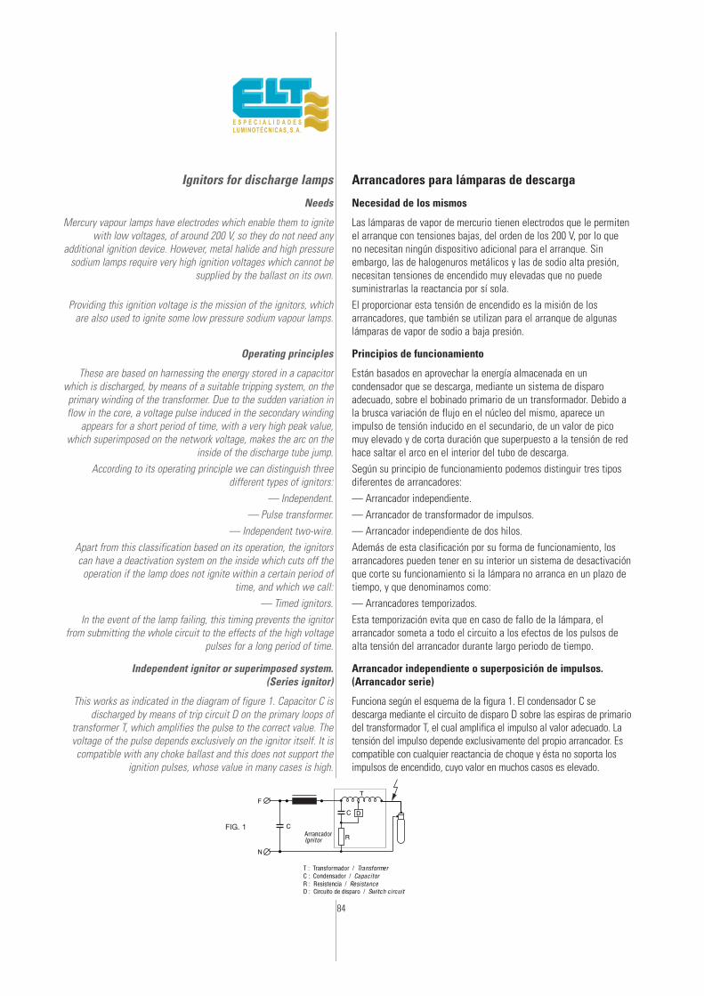
84
Ignitors for discharge lamps
Needs
Mercury vapour lamps have electrodes which enable them to ignitewith low voltages, of around 200 V, so they do not need any
additional ignition device. However, metal halide and high pressuresodium lamps require very high ignition voltages which cannot be
supplied by the ballast on its own.
Providing this ignition voltage is the mission of the ignitors, whichare also used to ignite some low pressure sodium vapour lamps.
Operating principles
These are based on harnessing the energy stored in a capacitorwhich is discharged, by means of a suitable tripping system, on theprimary winding of the transformer. Due to the sudden variation inflow in the core, a voltage pulse induced in the secondary winding
appears for a short period of time, with a very high peak value,which superimposed on the network voltage, makes the arc on the
inside of the discharge tube jump.According to its operating principle we can distinguish three
different types of ignitors:— Independent.
— Pulse transformer.— Independent two-wire.
Apart from this classification based on its operation, the ignitorscan have a deactivation system on the inside which cuts off the
operation if the lamp does not ignite within a certain period oftime, and which we call:
— Timed ignitors.In the event of the lamp failing, this timing prevents the ignitor
from submitting the whole circuit to the effects of the high voltagepulses for a long period of time.
Independent ignitor or superimposed system.(Series ignitor)
This works as indicated in the diagram of figure 1. Capacitor C isdischarged by means of trip circuit D on the primary loops of
transformer T, which amplifies the pulse to the correct value. Thevoltage of the pulse depends exclusively on the ignitor itself. It iscompatible with any choke ballast and this does not support the
ignition pulses, whose value in many cases is high.
Arrancadores para lámparas de descarga
Necesidad de los mismos
Las lámparas de vapor de mercurio tienen electrodos que le permitenel arranque con tensiones bajas, del orden de los 200 V, por lo queno necesitan ningún dispositivo adicional para el arranque. Sinembargo, las de halogenuros metálicos y las de sodio alta presión,necesitan tensiones de encendido muy elevadas que no puedesuministrarlas la reactancia por sí sola.El proporcionar esta tensión de encendido es la misión de losarrancadores, que también se utilizan para el arranque de algunaslámparas de vapor de sodio a baja presión.
Principios de funcionamiento
Están basados en aprovechar la energía almacenada en uncondensador que se descarga, mediante un sistema de disparoadecuado, sobre el bobinado primario de un transformador. Debido ala brusca variación de flujo en el núcleo del mismo, aparece unimpulso de tensión inducido en el secundario, de un valor de picomuy elevado y de corta duración que superpuesto a la tensión de redhace saltar el arco en el interior del tubo de descarga.Según su principio de funcionamiento podemos distinguir tres tiposdiferentes de arrancadores:— Arrancador independiente.— Arrancador de transformador de impulsos.— Arrancador independiente de dos hilos.Además de esta clasificación por su forma de funcionamiento, losarrancadores pueden tener en su interior un sistema de desactivaciónque corte su funcionamiento si la lámpara no arranca en un plazo detiempo, y que denominamos como:— Arrancadores temporizados.Esta temporización evita que en caso de fallo de la lámpara, elarrancador someta a todo el circuito a los efectos de los pulsos dealta tensión del arrancador durante largo periodo de tiempo.
Arrancador independiente o superposición de impulsos.(Arrancador serie)
Funciona según el esquema de la figura 1. El condensador C sedescarga mediante el circuito de disparo D sobre las espiras de primariodel transformador T, el cual amplifica el impulso al valor adecuado. Latensión del impulso depende exclusivamente del propio arrancador. Escompatible con cualquier reactancia de choque y ésta no soporta losimpulsos de encendido, cuyo valor en muchos casos es elevado.
F
N
T
C
C D
R
FIG. 1
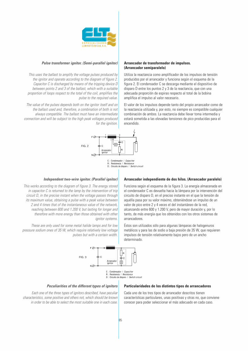
85
Pulse transformer ignitor. (Semi-parallel ignitor)
This uses the ballast to amplify the voltage pulses produced by the ignitor and operate according to the diagram of figure 2. Capacitor C is discharged by means of the tripping device D
between points 2 and 3 of the ballast, which with a suitableproportion of loops respect to the total of the coil, amplifies the
pulse to the required value.
The value of the pulses depends both on the ignitor itself and onthe ballast used and, therefore, a combination of both is not
always compatible. The ballast must have an intermediateconnection and will be subject to the high peak voltages produced
for the ignition.
Independent two-wire ignitor. (Parallel ignitor)
This works according to the diagram of figure 3. The energy storedin capacitor C is returned to the lamp by the intervention of trip
circuit D, in the precise instant when the voltage passes throughits maximum value, obtaining a pulse with a peak value between
2 and 4 times that of the instantaneous value of the network,reaching between 600 and 1.200 V, but lasting for longer and
therefore with more energy than those obtained with other ignitor systems.
These are only used for some metal halide lamps and for lowpressure sodium ones of 35 W, which require relatively low voltage
pulses but with a certain width.
Peculiarities of the different types of ignitors
Each one of the three types of ignitors described, have peculiarcharacteristics, some positive and others not, which should be known
in order to be able to select the most suitable one in each case.
Arrancador de transformador de impulsos.(Arrancador semiparalelo)
Utiliza la reactancia como amplificador de los impulsos de tensiónproducidos por el arrancador y funciona según el esquema de lafigura 2. El condensador C se descarga mediante el dispositivo dedisparo D entre los puntos 2 y 3 de la reactancia, que con unaadecuada proporción de espiras respecto al total de la bobinaamplifica el impulso al valor necesario.
El valor de los impulsos depende tanto del propio arrancador como dela reactancia utilizada y, por esto, no siempre es compatible cualquiercombinación de ambos. La reactancia debe llevar toma intermedia yestará sometida a las elevadas tensiones de pico producidas para elencendido.
Arrancador independiente de dos hilos. (Arrancador paralelo)
Funciona según el esquema de la figura 3. La energía almacenada enel condensador C es devuelta hacia la lámpara por la intervención delcircuito de disparo D, en el preciso instante en el que la tensión deaquélla pasa por su valor máximo, obteniéndose un impulso de unvalor de pico entre 2 y 4 veces el del instantáneo de la red,alcanzando entre 600 y 1.200 V, pero de mayor duración y, por lotanto, de más energía que los obtenidos con los otros sistemas dearrancadores.
Éstos son utilizados sólo para algunas lámparas de halogenurosmetálicos y para las de sodio a baja presión de 35 W, que requierenimpulsos de tensión relativamente bajos pero de un anchodeterminado.
Particularidades de los distintos tipos de arrancadores
Cada uno de los tres tipos de arrancador descritos tienencaracterísticas particulares, unas positivas y otras no, que convieneconocer para poder seleccionar el más adecuado en cada caso.
F
N
C
CD
R
F
N
C C
D
R
FIG. 2
FIG. 3
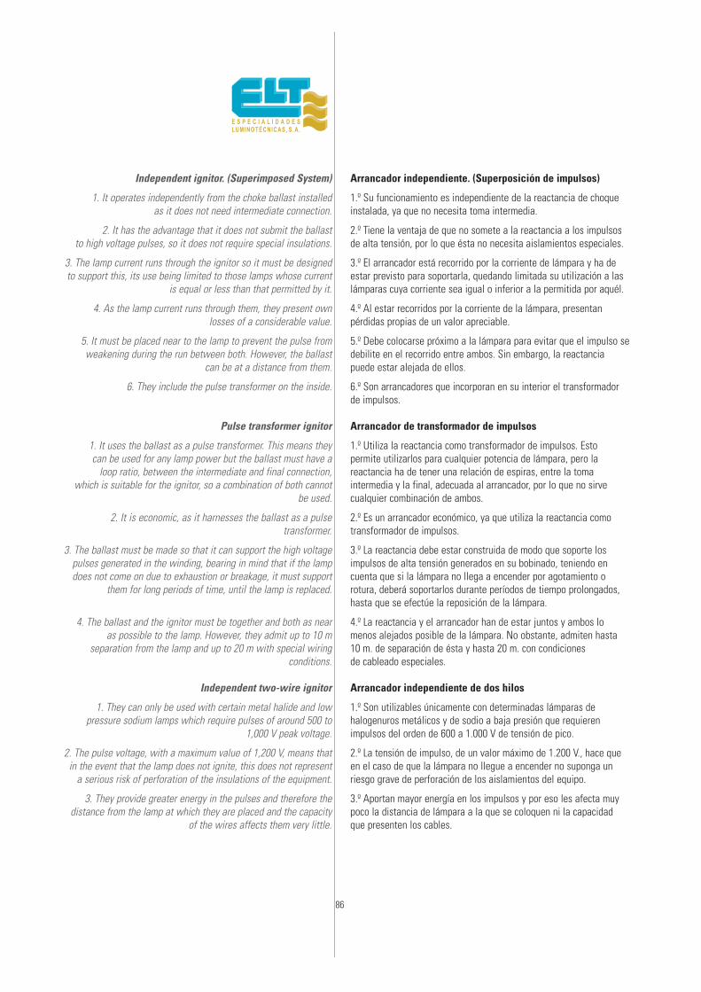
86
Independent ignitor. (Superimposed System)
1. It operates independently from the choke ballast installed as it does not need intermediate connection.
2. It has the advantage that it does not submit the ballast to high voltage pulses, so it does not require special insulations.
3. The lamp current runs through the ignitor so it must be designedto support this, its use being limited to those lamps whose current
is equal or less than that permitted by it.
4. As the lamp current runs through them, they present own losses of a considerable value.
5. It must be placed near to the lamp to prevent the pulse fromweakening during the run between both. However, the ballast
can be at a distance from them.
6. They include the pulse transformer on the inside.
Pulse transformer ignitor
1. It uses the ballast as a pulse transformer. This means they can be used for any lamp power but the ballast must have a
loop ratio, between the intermediate and final connection, which is suitable for the ignitor, so a combination of both cannot
be used.
2. It is economic, as it harnesses the ballast as a pulsetransformer.
3. The ballast must be made so that it can support the high voltagepulses generated in the winding, bearing in mind that if the lampdoes not come on due to exhaustion or breakage, it must support
them for long periods of time, until the lamp is replaced.
4. The ballast and the ignitor must be together and both as near as possible to the lamp. However, they admit up to 10 m
separation from the lamp and up to 20 m with special wiringconditions.
Independent two-wire ignitor
1. They can only be used with certain metal halide and lowpressure sodium lamps which require pulses of around 500 to
1,000 V peak voltage.
2. The pulse voltage, with a maximum value of 1,200 V, means thatin the event that the lamp does not ignite, this does not represent
a serious risk of perforation of the insulations of the equipment.
3. They provide greater energy in the pulses and therefore thedistance from the lamp at which they are placed and the capacity
of the wires affects them very little.
Arrancador independiente. (Superposición de impulsos)
1.º Su funcionamiento es independiente de la reactancia de choqueinstalada, ya que no necesita toma intermedia.
2.º Tiene la ventaja de que no somete a la reactancia a los impulsosde alta tensión, por lo que ésta no necesita aislamientos especiales.
3.º El arrancador está recorrido por la corriente de lámpara y ha deestar previsto para soportarla, quedando limitada su utilización a laslámparas cuya corriente sea igual o inferior a la permitida por aquél.
4.º Al estar recorridos por la corriente de la lámpara, presentanpérdidas propias de un valor apreciable.
5.º Debe colocarse próximo a la lámpara para evitar que el impulso sedebilite en el recorrido entre ambos. Sin embargo, la reactanciapuede estar alejada de ellos.
6.º Son arrancadores que incorporan en su interior el transformadorde impulsos.
Arrancador de transformador de impulsos
1.º Utiliza la reactancia como transformador de impulsos. Estopermite utilizarlos para cualquier potencia de lámpara, pero lareactancia ha de tener una relación de espiras, entre la tomaintermedia y la final, adecuada al arrancador, por lo que no sirvecualquier combinación de ambos.
2.º Es un arrancador económico, ya que utiliza la reactancia comotransformador de impulsos.
3.º La reactancia debe estar construida de modo que soporte losimpulsos de alta tensión generados en su bobinado, teniendo encuenta que si la lámpara no llega a encender por agotamiento orotura, deberá soportarlos durante períodos de tiempo prolongados,hasta que se efectúe la reposición de la lámpara.
4.º La reactancia y el arrancador han de estar juntos y ambos lomenos alejados posible de la lámpara. No obstante, admiten hasta 10 m. de separación de ésta y hasta 20 m. con condiciones de cableado especiales.
Arrancador independiente de dos hilos
1.º Son utilizables únicamente con determinadas lámparas dehalogenuros metálicos y de sodio a baja presión que requierenimpulsos del orden de 600 a 1.000 V de tensión de pico.
2.º La tensión de impulso, de un valor máximo de 1.200 V., hace queen el caso de que la lámpara no llegue a encender no suponga unriesgo grave de perforación de los aislamientos del equipo.
3.º Aportan mayor energía en los impulsos y por eso les afecta muypoco la distancia de lámpara a la que se coloquen ni la capacidadque presenten los cables.

87
Timed ignitors
These are ignitors with an internal device which after a presetpulse production time, de-activates the operation. So, if the lampdoes not ignite due to exhaustion or fault, it stops submitting the
whole circuit to the high voltage pulses.
The ignitor becomes active again after the interruptionof the supply voltage of the circuit although only for a short space
of time (milliseconds).
ELT manufactures two types of ignitor with two different cut-outtimes.
Type Cut-out time UseT5 5 min. For high pressure sodium vapour lampsT15-T20 15-20 min. For metal halide lamps
Standards of reference
The standards applicable to the ignitors, and according to whichthe ELT products are manufactured, are:
EN 61347-2-1 Devices for lamps-part 2-1: particularrequirements for starting devices (other than
glow starters).
EN 60927 Startings devices (other than glow starters).Performance requirements.
EN 60662 High pressure sodium vapour lamps.
EN 61167 Metal halide lamps.
Recomendations for the use of ignitors
— Firstly we must choose the ignitor which adapts to the lampswe wish to install, so that they provide us with:
a) The necessary peak voltage,
b) number of pulses required to ignite the lamp, and
c) admit the load capacity represented by the wires to the lamp.
— Care must be taken to locate them so that there is always aminimum distance from the ignitor to the lamp, so that the wirecapacity is minimum and thus ensure the ignition. This capacitydepends on the separation between the wires and their length.
Hoses, as the conductors are close together and braided, presenthigh capacities (between 70 and 150 pf/m) whilst one-wire cables
with good insulation present much lower capacities(from 20 to 50 pf/m).
— The conductor bearing the high voltage pulse which isindicated on all the ignitors, must have an insulation for a service
voltage of not less than 1 KV (Test voltage 3 KV). And beconnected to the central contact of the lamp-socket in order to
favour the ignition.
Arrancadores temporizadores
Son arrancadores con un dispositivo interno que tras un tiempoprefijado de producción de impulsos, desactiva el funcionamiento delmismo. Si la lámpara no enciende por agotamiento o avería, deja desometer a los impulsos de alta tensión a todo el circuito.
El arrancador vuelve a estar activo tras la interrupción de la tensiónde alimentación del circuito aunque sólo sea por un corto espacio detiempo (milisegundos).
ELT fabrica dos tipos de arrancador con dos diferentes tiempos detemporización o de desactivado.
Tipo Temporización UsoT5 5 min. Para lámpara de vapor de sodio a alta presiónT15-T20 15-20 min. Para lámparas de halogenuros metálicos
Normas de referencia
Las normas aplicables a los arrancadores y según las cuales estánfabricados los de ELT, son:
EN 61347-2-1 Aparatos auxiliares para lámpara-parte 2-1: requisitosparticulares para arrancadores (excepto arrancadoresde destellos).
EN 60927 Aparatos arrancadores y cebadores (excepto los deefluvios). Prescripciones de funcionamiento.
EN 60662 Lámparas de Vapor de Sodio a alta presión.
EN 61167 Lámparas de halogenuros metálicos.
Recomendaciones para el uso de arrancadores
— En primer lugar debemos elegir el arrancador adecuado paralámparas que deseamos instalar, de forma que nos proporcione:
a) El voltaje de pico necesario,
b) número de impulsos exigidos para encender la lámpara, y
c) admita la capacidad de carga que suponen los cables hasta lalámpara.
— Debe cuidarse la ubicación de manera que haya siempre lamínima distancia desde el arrancador a la lámpara, para que lacapacidad de los cables sea mínima y así asegurar el encendido.Dicha capacidad depende de la separación entre sí de los cables y desu longitud. Los cables manguera, al tener los conductores muypróximos y trenzados, presentan capacidades altas (entre 70 y 150pf/m), mientras que los cables unifilares con buen aislamientopresentan capacidades mucho más bajas (de 20 a 50 pf/m).
— El conductor portador del impulso de la alta tensión, el cual seindica en todos los arrancadores, debe de ser de un aislamiento paratensión de servicio no menor de 1 kV (Tensión de prueba 3 KV). Yestar conectado al contacto central del portalámparas para favorecerel encendido de la misma.

88
— Always respect the connection indicated on the ignitordiagram.
— Avoid humidity in the ignitor housing, as well as water orcondensation as this can cause bypasses between terminals or to
earth which would cancel the high voltage pulse, not producing theignition.
— Excessive ambient temperatures must also be avoided asthese can cause overheating in the ignitor and can endanger
its duration.
The temperature at the point indicated on its surface must notexceed the value indicater for tc ... °C, when the lamp is operating
and thermally stabilised.
— The ignitor produces voltages of up to 5 KV so special caremust be taken of the insulations of the cables which support them
and never work on the light fitting without being sure that thesupply voltage has been cut-off.
— Keep the power factor correction capacitor connected in orderto avoid pulse losses towards the network.
Typical parameters of the ignitors
Below a description is given of the electric parameters of theignitors, whose values are given on the characteristics sheets of
each type.
Switch-on voltage: This is the maximum line voltage at whichthe ignitor must begin to give high voltage pulses.
Switch-off voltage: Minimum line voltage at which the ignitormust stop producing pulses.
Main voltage: Range of line voltages within which the ignitor canoperate.
Peak voltage of the pulses: This is the maximum value of thepulses generated by the ignitor. If this is lower than that required
for the ignition, the lamps cannot ignite. If it is higher than thevalue permitted by the insulations of the lamp-sockets and lamp
sleeves, this can spoil them.
Pulse width at “X” KV: Width of the pulse measured at “X” KVwhich must be reached to ensure sufficient energy for the
ignition.
Number of pulses: Number of pulses produced for each period ofthe suply voltage.
Impulse position: Position in electric degrees where the pulses ofthis voltage occur in each semi-period of the supply voltage.
Load capacitance: Maximum load capacity admitted by theignitor for correct operation.
Own losses: The value of losses caused by the ignitor whenthis is working with the maximum permissible current.
— Respetar siempre la forma del conexionado que se indica en elesquema del arrancador.
— Evitar que en el alojamiento del arrancador pueda haber humedad,entrada de agua o condensaciones, ya que ello puede provocarderivaciones entre terminales o a tierra que nos anularían el impulsode alta tensión, no produciéndose el encendido.
— También hay que evitar una excesiva temperatura ambiente quepueda provocar un sobrecalentamiento en el arrancador y ponga enpeligro su duración.
La temperatura en el punto que se indica en la superficie delarrancador, no debe sobrepasar el valor indicado para tc ....°C,cuando la lámpara está funcionando y estabilizada térmicamente.
— El arrancador produce tensiones de hasta 5 KV; por ello debencuidarse especialmente los aislamientos de los cables que lossoportan y no trabajar nunca en la luminaria sin estar seguros de quela tensión de alimentos está cortada.
— Tener conectado el condensador de corrección del factor depotencia para evitar pérdidas de impulso hacia la red.
Parámetros característicos de los arrancadores
A continuación se describen los parámetros eléctricos de losarrancadores, cuyos valores se encuentran en las hojas decaracterísticas de cada tipo de arrancador.
Tensión de arranque: Es la máxima tensión de línea a la que elarrancador debe comenzar a dar impulsos de alta tensión.
Tensión de desconexión: Tensión mínima de línea a la cual elarrancador debe dejar de producir impulsos.
Tensión de vacío: Rango de tensiones de línea en la que puedefuncionar el arrancador.
Tensión de pico de los impulsos: Es el valor máximo de losimpulsos generados por el arrancador. Si es más bajo que elrequerido para la ignición, las lámparas pueden no encender. Si esmás alto del valor permitido por los aislamientos de losportalámparas y casquillos de las lámparas, puede estropearlos.
Anchura del impulso a “X” KV: Anchura del impulso medido a “X”KV, que debe ser alcanzado para asegurar la suficiente aportación deenergía para el encendido.
Número de impulsos: Número de impulsos producidos por cadaperiodo de la tensión de alimentación.
Posición de fase: Posición en grados eléctricos donde se producenlos impulsos de esta tensión en cada semi-periodo de la tensión dealimentación.
Capacidad de carga: La máxima capacidad de carga admitida porel arrancador para un correcto funcionamiento.
Pérdidas propias: El valor de pérdidas originadas por el arrancadorcuando está funcionando con la máxima corriente permitida.

89
Normal heating: Maximum temperature increase in the ignitorcasing at the point indicated, over the ambient temperature where
it is working, under normal conditions.
Temperature admitted in the casing (tc): Maximum admissibletemperature in the ignitor casing to guarantee the life expectation
foreseen.
Ambient temperature of use (ta): Range of ambienttemperatures (minimum-maximum) at which the ignitor can operate
in order to guarantee the life expectation foreseen.
Timing: Approximate time after which, if the lamp has not ignited,the ignitor is deactivated until a new re-activation due to cut-off
and rest of the supply voltage.
Calentamiento normal: Aumento máximo de temperatura en laenvolvente del arrancador en el punto indicado, sobre el ambiente enel que se halla funcionando, en condiciones normales.
Temperatura admitida en el envolvente (tc): Máxima temperaturaadmisible en la envolvente del arrancador para garantizar laexpectativa de vida prevista.
Temperatura ambiente de utilización (ta): Rango de temperaturasambiente (mínima-máxima) a las que puede funcionar el arrancadorpara garantizar la expectativa de vida prevista.
Temporización: Tiempo aproximado tras el cual, si la lámpara no haencendido, el arrancador queda desactivado hasta una nuevareactivación por corte y reposición de la tensión de alimentación.

AVS-100-1
AVS-100-4-T5
AVS-100-4-T15
AVS-70
AVS-150
AVS-150-T2
AVS-150-T10
AVS-400-R
AVS-400
AVS-400-T2
AVS-400-T10
AVS-1000
AH-1000
AVS-2000/380
AH-2000/220
AH-005/380
AH-002-1
ASB-55
IG TABLA PARA LA SELECCIÓN DE ARRANCADORESLIST FOR THE CHOICE OF THE SUITABLE IGNITOR
90
Tipo de arrancadorIgnitor type
W
AVS-003-1(3)
Lámparas de Vapor de Sodio APSHP Lamps
50
• • • • • •
• • • • • • • •
• •
• •
• • • • • •
• • • • • • • •
• • • •
• • • •
• • • •
• • • •
• • • •
• • • •
• • • •
••••• •
• • • •
• • • •
• • •
• • • •
• • • • •
• • • • •
•
•
•
•
• • • •
70 100 150 250 400 600 1000 35 35 5570 100 150 250 400 10002000
220
Lámparas de halogenuros metálicosMH Lamps
Lámparassodio BPLPS Lamps
2000
380
(1)
•(2)
•
•
•(2)
•(2)
•(2)
(1) Para lámparas de tensión de encendi-do 1,2kV.Suitable for lamps with pulse peakvoltage 1,2kV.
(2) Válido para lámparas de tensión deencendido 0,8kV.Suitable for lamps with pulse peakvoltage 0,8kV.
(3) Sólo para lámpara standard.Only suitable for standard lamps
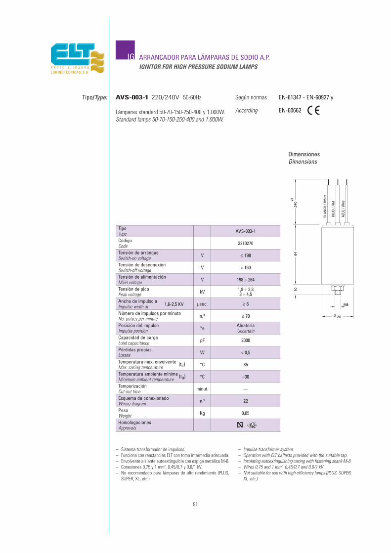
91
IG ARRANCADOR PARA LÁMPARAS DE SODIO A.P.IGNITOR FOR HIGH PRESSURE SODIUM LAMPS
Tipo/Type:
DimensionesDimensions
Según normas
According
EN-61347 - EN-60927 y
EN-60662
– Sistema transformador de impulsos.– Funciona con reactancias ELT con toma intermedia adecuada.– Envolvente aislante autoextinguible con espiga metálica M-8.– Conexiones 0,75 y 1 mm2, 0,45/0,7 y 0,6/1 kV.– No recomendado para lámparas de alto rendimiento (PLUS,
SUPER, XL, etc.).
– Impulse transformer system.– Operation with ELT ballasts provided with the suitable tap.– Insulating autoextinguishing casing with fastening shank M-8.– Wires 0,75 and 1 mm2, 0,45/0,7 and 0,6/1 kV.– Not suitable for use with high efficiency lamps (PLUS, SUPER,
XL, etc.).
AVS-003-1 220/240V 50-60Hz
Lámparas standard 50-70-150-250-400 y 1.000W.Standard lamps 50-70-150-250-400 and 1.000W.
TipoType AVS-003-1
240
6410
M8
30
±5
Tensión de arranqueSwitch-on voltage
Tensión de alimentaciónMain voltage
Ancho de impulso a1,6-2,5 KVImpulse width at
Posición del impulsoImpulse position
V
V
µsec.
°e
≤ 198
198 ÷ 264
≥ 6
AleatoriaUncertain
Pérdidas propiasLosses W < 0,5
CódigoCode 3210270
Tensión de desconexiónSwitch-off voltage V > 160
Tensión de picoPeak voltage kV 1,8 ÷ 2,3
3 ÷ 4,5
Número de impulsos por minutoNo. pulses per minute n.° ≥ 70
Capacidad de cargaLoad capacitance pF 2000
Temperatura máx. envolvente (tc)Max. casing temperature °C 85
TemporizaciónCut-out time minut. ––
PesoWeight Kg 0,05
Temperatura ambiente mínima (ta)Minimum ambient temperature °C –30
Esquema de conexionadoWiring diagram n.º 22
HomologacionesApprovals
01
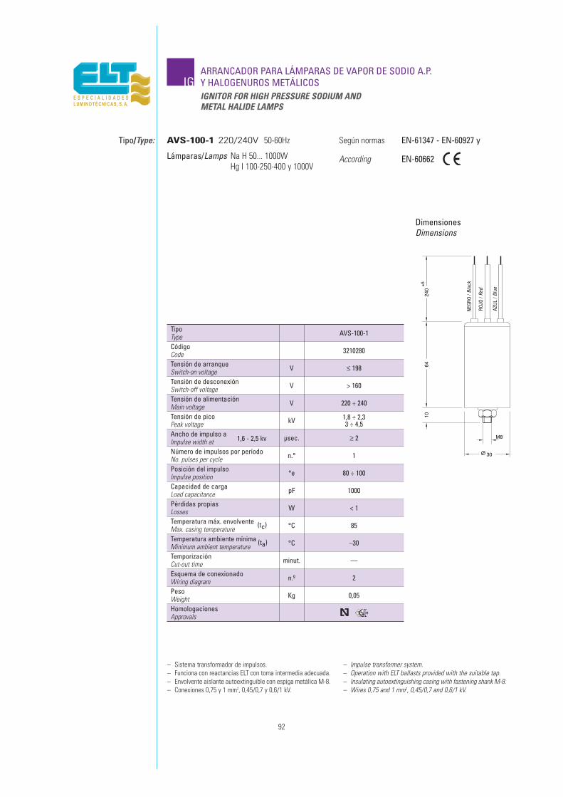
92
IGARRANCADOR PARA LÁMPARAS DE VAPOR DE SODIO A.P.Y HALOGENUROS METÁLICOSIGNITOR FOR HIGH PRESSURE SODIUM ANDMETAL HALIDE LAMPS
Tipo/Type:
DimensionesDimensions
Según normas
According
EN-61347 - EN-60927 y
EN-60662
– Sistema transformador de impulsos.– Funciona con reactancias ELT con toma intermedia adecuada.– Envolvente aislante autoextinguible con espiga metálica M-8.– Conexiones 0,75 y 1 mm2, 0,45/0,7 y 0,6/1 kV.
– Impulse transformer system.– Operation with ELT ballasts provided with the suitable tap.– Insulating autoextinguishing casing with fastening shank M-8.– Wires 0,75 and 1 mm2, 0,45/0,7 and 0,6/1 kV.
AVS-100-1 220/240V 50-60Hz
Lámparas/Lamps Na H 50... 1000WHg I 100-250-400 y 1000V
TipoType AVS-100-1
240
6410
M8
30
±5
Tensión de arranqueSwitch-on voltage
Tensión de alimentaciónMain voltage
Ancho de impulso a1,6 - 2,5 kvImpulse width at
Posición del impulsoImpulse position
V
V
µsec.
°e
≤ 198
220 ÷ 240
≥ 2
80 ÷ 100
Pérdidas propiasLosses W < 1
CódigoCode 3210280
Tensión de desconexiónSwitch-off voltage V > 160
Tensión de picoPeak voltage kV 1,8 ÷ 2,3
3 ÷ 4,5
Número de impulsos por períodoNo. pulses per cycle n.° 1
Capacidad de cargaLoad capacitance pF 1000
Temperatura máx. envolvente (tc)Max. casing temperature °C 85
TemporizaciónCut-out time minut. ––
PesoWeight Kg 0,05
°C –30
Esquema de conexionadoWiring diagram n.º 2
HomologacionesApprovals
Temperatura ambiente mínima (ta)Minimum ambient temperature
01
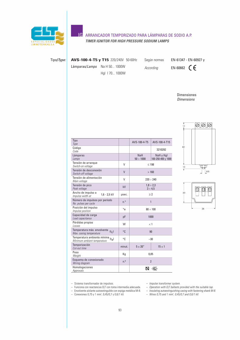
0,05
93
IG ARRANCADOR TEMPORIZADO PARA LÁMPARAS DE SODIO A.P.TIMER IGNITOR FOR HIGH PRESSURE SODIUM LAMPS
Tipo/Type:
DimensionesDimensions
Según normas
According
EN-61347 - EN-60927 y
EN-60662
– Sistema transformador de impulsos.– Funciona con reactancias ELT con toma intermedia adecuada.– Envolvente aislante autoextinguible con espiga metálica M-8.– Conexiones 0,75 y 1 mm2, 0,45/0,7 y 0,6/1 kV.
– Impulse transformer system.– Operation with ELT ballasts provided with the suitable tap.– Insulating autoextinguishing casing with fastening shank M-8.– Wires 0,75 and 1 mm2, 0,45/0,7 and 0,6/1 kV.
AVS-100-4-T5 y T15 220/240V 50-60Hz
Lámparas/Lamps Na H 50... 1000W
HgI I 70... 1000W
TipoType AVS-100-4-T5 AVS-100-4-T15
3210292
Tensión de arranqueSwitch-on voltage
Tensión de alimentaciónMain voltage
Ancho de impulso a1,6 - 2,5 kVImpulse width at
Posición del impulsoImpulse position
V
V
µsec.
°e
≤ 198
220 ÷ 240
≥ 2
80 ÷ 100
Pérdidas propiasLosses W < 1
CódigoCodeLámparasLamps
NaH50 ÷ 1000
NaH y HgI100-250-400 y 1000
Tensión de desconexiónSwitch-off voltage V > 160
Tensión de picoPeak voltage kV 1,8 ÷ 2,3
3 ÷ 4,5
Número de impulsos por períodoNo. pulses per cycle n.° 1
Capacidad de cargaLoad capacitance pF 1000
Temperatura máx. envolvente (tc)Max. casing temperature °C 90
TemporizaciónCut-out time minut. 5 ± 20” 15 ± 1
Esquema de conexionadoWiring diagram
Kg
Temperatura ambiente mínima (ta)Minimum ambient temperature °C –30
PesoWeight
n.º 2
HomologacionesApprovals
01
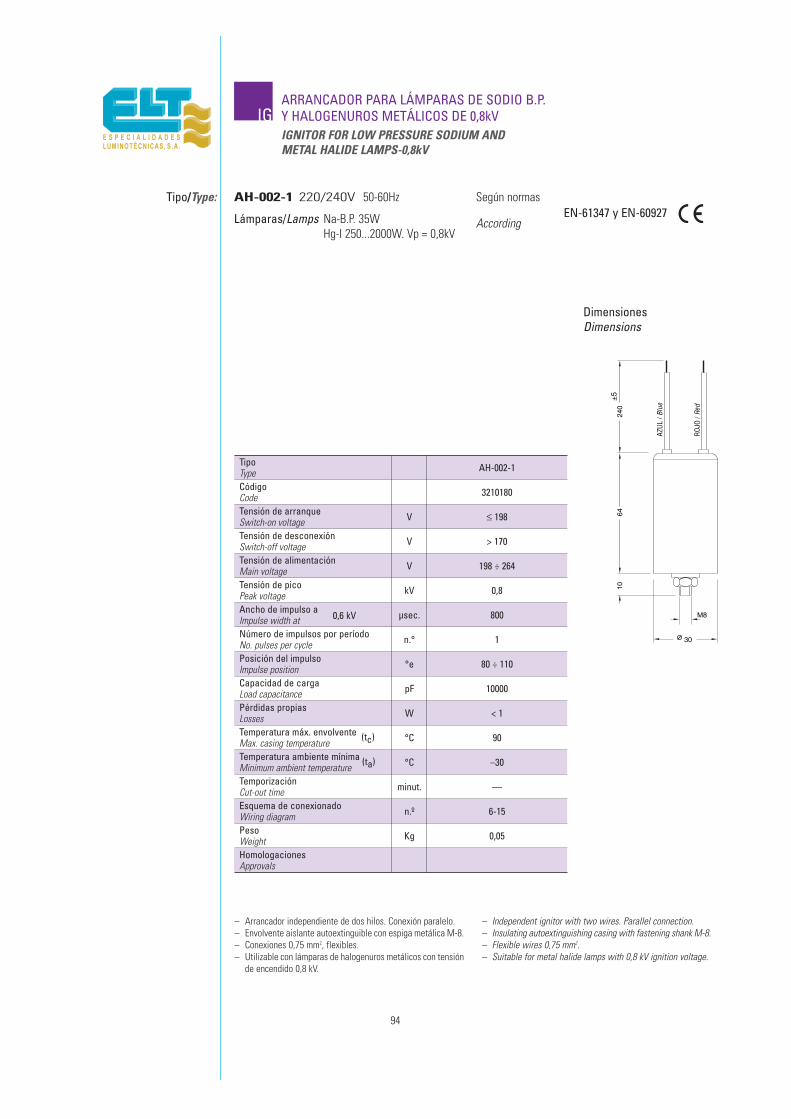
94
IGARRANCADOR PARA LÁMPARAS DE SODIO B.P.Y HALOGENUROS METÁLICOS DE 0,8kVIGNITOR FOR LOW PRESSURE SODIUM ANDMETAL HALIDE LAMPS-0,8kV
Tipo/Type:
DimensionesDimensions
Según normas
AccordingEN-61347 y EN-60927
– Arrancador independiente de dos hilos. Conexión paralelo.– Envolvente aislante autoextinguible con espiga metálica M-8.– Conexiones 0,75 mm2, flexibles.– Utilizable con lámparas de halogenuros metálicos con tensión
de encendido 0,8 kV.
– Independent ignitor with two wires. Parallel connection.– Insulating autoextinguishing casing with fastening shank M-8.– Flexible wires 0,75 mm2.– Suitable for metal halide lamps with 0,8 kV ignition voltage.
AH-002-1 220/240V 50-60Hz
Lámparas/Lamps Na-B.P. 35WHg-I 250...2000W. Vp = 0,8kV
TipoType AH-002-1
240
6410
M8
30
±5
Tensión de arranqueSwitch-on voltage
Tensión de alimentaciónMain voltage
Ancho de impulso a0,6 kVImpulse width at
Posición del impulsoImpulse position
V
V
µsec.
°e
≤ 198
198 ÷ 264
800
80 ÷ 110
Pérdidas propiasLosses W < 1
CódigoCode 3210180
Tensión de desconexiónSwitch-off voltage V > 170
Tensión de picoPeak voltage kV 0,8
Número de impulsos por períodoNo. pulses per cycle n.° 1
Capacidad de cargaLoad capacitance pF 10000
Temperatura máx. envolvente (tc)Max. casing temperature °C 90
TemporizaciónCut-out time minut. ––
PesoWeight Kg 0,05
Temperatura ambiente mínima (ta)Minimum ambient temperature °C –30
Esquema de conexionadoWiring diagram n.º 6-15
HomologacionesApprovals
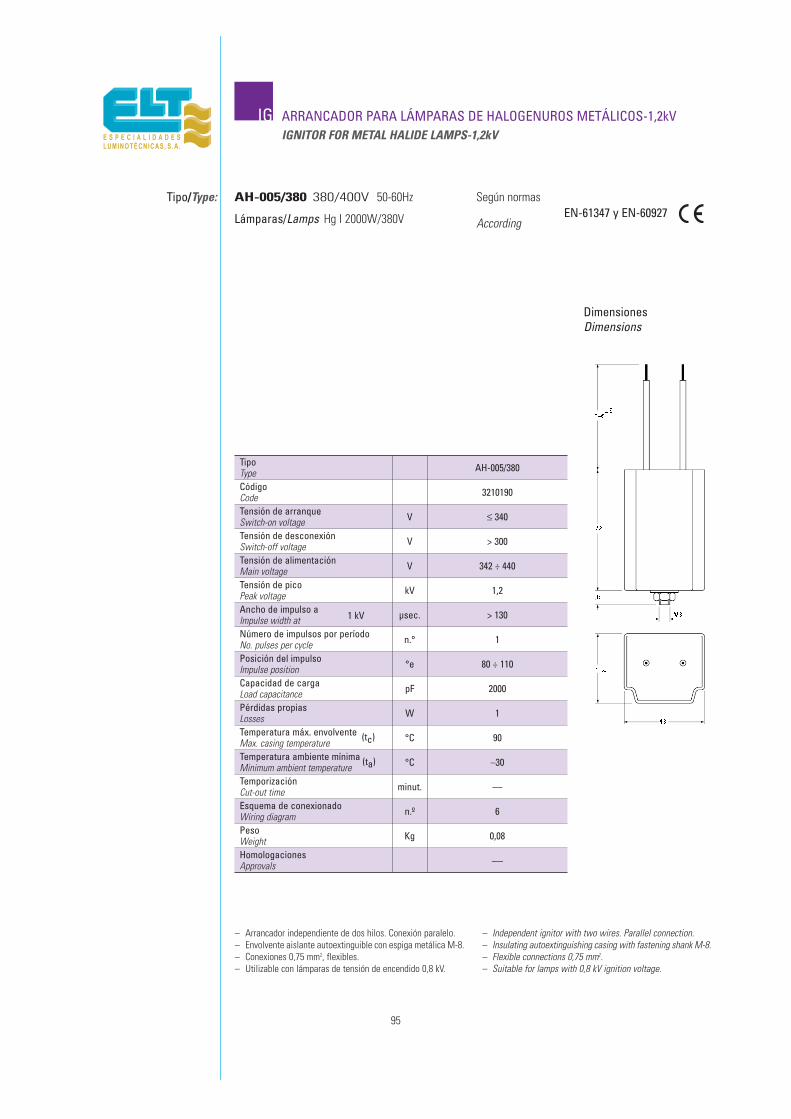
95
IG ARRANCADOR PARA LÁMPARAS DE HALOGENUROS METÁLICOS-1,2kVIGNITOR FOR METAL HALIDE LAMPS-1,2kV
Tipo/Type:
DimensionesDimensions
Según normas
AccordingEN-61347 y EN-60927
– Arrancador independiente de dos hilos. Conexión paralelo.– Envolvente aislante autoextinguible con espiga metálica M-8.– Conexiones 0,75 mm2, flexibles.– Utilizable con lámparas de tensión de encendido 0,8 kV.
– Independent ignitor with two wires. Parallel connection.– Insulating autoextinguishing casing with fastening shank M-8.– Flexible connections 0,75 mm2.– Suitable for lamps with 0,8 kV ignition voltage.
AH-005/380 380/400V 50-60Hz
Lámparas/Lamps Hg I 2000W/380V
TipoType AH-005/380
Tensión de arranqueSwitch-on voltage
Tensión de alimentaciónMain voltage
Ancho de impulso a1 kVImpulse width at
Posición del impulsoImpulse position
V
V
µsec.
°e
≤ 340
342 ÷ 440
> 130
80 ÷ 110
Pérdidas propiasLosses W 1
CódigoCode 3210190
Tensión de desconexiónSwitch-off voltage V > 300
Tensión de picoPeak voltage kV 1,2
Número de impulsos por períodoNo. pulses per cycle n.° 1
Capacidad de cargaLoad capacitance pF 2000
Temperatura máx. envolvente (tc)Max. casing temperature °C 90
TemporizaciónCut-out time minut. ––
PesoWeight Kg 0,08
Temperatura ambiente mínima (ta)Minimum ambient temperature °C –30
Esquema de conexionadoWiring diagram n.º 6
HomologacionesApprovals ––

IG ARRANCADOR PARA LÁMPARAS DE SODIO A.P.IGNITOR FOR HIGH PRESSURE SODIUM
Tipo/Type:
DimensionesDimensions
Según normas
According
– Sistema superposición de impulsos. Independiente.– Utilización universal hasta 2A.– Envolvente aislante autoextinguible con espiga metálica M-8.– Terminales de poliamida 0,75 ÷ 2,5 mm2.– Encapsulado en resina de poliuretano.
– Superimposed system. Independent type.– Universal use up to 2A.– Insulating autoextinguishing casing with fastening shank M-8.– Terminal block in polyamide 0,75 ÷ 2,5 mm2.– Encapsulated in polyurethane resin.
AVS-70 220/240V 50-60Hz
Lámparas/Lamps NaH 50 y 70WI. máx. 2A
TipoType AVS-70
Tensión de arranqueSwitch-on voltage
Tensión de alimentaciónMain voltage
Ancho de impulso a1,5 kVImpulse width at
Posición del impulsoImpulse position
V
V
µsec.
°e
≤ 198
198 ÷ 264
≥ 0,7
60-90240-270
Pérdidas propias a 1ALosses at W 1,5
CódigoCode 3210420
Tensión de desconexiónSwitch-off voltage V > 170
Tensión de picoPeak voltage kV 1,8 - 2,3
Número de impulsos por períodoNo. pulses per cycle n.° 6
Capacidad de cargaLoad capacitance pF 200
Temperatura máx. envolvente (tc)Max. casing temperature °C 105
TemporizaciónCut-out time minut. ––
PesoWeight Kg 0,15
Temperatura ambiente mínima (ta)Minimum ambient temperature °C –30
Esquema de conexionadoWiring diagram n.º 3
HomologacionesApprovals
EN-61347 - EN-60927 y
EN-60662
96
01

IGARRANCADOR PARA LÁMPARAS DE SODIO A.P.Y HALOGENUROS METÁLICOSIGNITOR FOR HIGH PRESSURE SODIUM AND METAL HALIDE LAMPS
Tipo/Type:
DimensionesDimensions
Según normas
According
– Sistema superposición de impulsos. Independiente.– Utilización universal hasta 2A.– Envolvente aislante autoextinguible con espiga metálica M-8.– Terminales de poliamida 0,75 ÷ 2,5 mm2.– Encapsulado en resina de poliuretano.
– Superimposed system. Independent type.– Universal use up to 2A.– Insulating autoextinguishing casing with fastening shank M-8.– Terminal block in polyamide 0,75 ÷ 2,5 mm2.– Encapsulated in polyurethane resin.
AVS-150 220/240V 50-60Hz
Lámparas/Lamps 35-50-70-100 y 150WI. máx. 2A
TipoType AVS-150
Tensión de arranqueSwitch-on voltage
Tensión de alimentaciónMain voltage
Ancho de impulso a2,5 kVImpulse width at
Posición del impulsoImpulse position
V
V
µsec.
°e
≤ 198
198 ÷ 264
≥ 0,5
60-90240-270
Pérdidas propias a 2ALosses at W 2,2
CódigoCode 3210151
Tensión de desconexiónSwitch-off voltage V > 170
Tensión de picoPeak voltage kV 3 ÷ 4,5
Número de impulsos por períodoNo. pulses per cycle n.° 6
Capacidad de cargaLoad capacitance pF 100
Temperatura máx. envolvente (tc)Max. casing temperature °C 105
TemporizaciónCut-out time minut. ––
PesoWeight Kg 0,15
Temperatura ambiente mínima (ta)Minimum ambient temperature °C –30
Esquema de conexionadoWiring diagram n.º 3
HomologacionesApprovals
EN-61347 - EN-60927 y
EN-60662
97
01

TipoType AVS-400R
Tensión de arranqueSwitch-on voltage
Tensión de alimentaciónMain voltage
Ancho de impulso a2,5 kVImpulse width at
Posición del impulsoImpulse position
V
V
µsec.
°e
≤ 198
198 ÷ 264
≥ 0,6
60-90240-270
Pérdidas propias a 4,6ALosses at W 2,4
CódigoCode 3110227
Tensión de desconexiónSwitch-off voltage V > 170
Tensión de picoPeak voltage kV 3 ÷ 4,5
Número de impulsos por períodoNo. pulses per cycle n.° 6
Capacidad de cargaLoad capacitance pF 100
Temperatura máx. envolvente (tc)Max. casing temperature °C 105
TemporizaciónCut-out time minut. ––
PesoWeight Kg 0,2
Temperatura ambiente mínima (ta)Minimum ambient temperature °C –30
Esquema de conexionadoWiring diagram n.º 3
HomologacionesApprovals
IGARRANCADOR PARA LÁMPARAS DE SODIO A.P.Y HALOGENUROS METÁLICOSIGNITOR FOR HIGH PRESSURE SODIUM AND METAL HALIDE LAMPS
Tipo/Type:
DimensionesDimensions
Según normas
According
AVS-400R 220/240V 50-60Hz
Lámparas/Lamps Na H 100-150-250 y 400WHg I 35 a 400WI. máx. 4,6A
EN-61347 - EN-60927 y
EN-60662
– Arrancador Independiente. Sistema superposición de impulsos.– Utilización universal hasta 4,6A.– Envolvente aislante autoextinguible con espiga metálica M-8.– Terminales de poliamida 0,75 ÷ 2,5 mm2.– Encapsulado en resina de poliuretano.
– Independent ignitor. Superimposed system.– Universal use up to 4,6A.– Insulating autoextinguishing casing with fastening shank M-8.– Terminal block in polyamide 0,75 ÷ 2,5 mm2.– Encapsulated in polyurethane resin.
98
01

TipoType AVS-400
Tensión de arranqueSwitch-on voltage
Tensión de alimentaciónMain voltage
Ancho de impulso a2,5 kVImpulse width at
Posición del impulsoImpulse position
V
V
µsec.
°e
≤ 198
198 ÷ 264
≥ 0,75
60-90240-270
Pérdidas propias a 4,6ALosses at W 3,5
CódigoCode 3210500
Tensión de desconexiónSwitch-off voltage V > 170
Tensión de picoPeak voltage kV 3 ÷ 4,5
Número de impulsos por períodoNo. pulses per cycle n.° 6
Capacidad de cargaLoad capacitance pF 100
Temperatura máx. envolvente (tc)Max. casing temperature °C 105
TemporizaciónCut-out time minut. ––
PesoWeight Kg 0,3
Temperatura ambiente mínima (ta)Minimum ambient temperature °C –30
Esquema de conexionadoWiring diagram n.º 3
HomologacionesApprovals
IGARRANCADOR PARA LÁMPARAS DE SODIO A.P.Y HALOGENUROS METÁLICOSIGNITOR FOR HIGH PRESSURE SODIUM AND METAL HALIDE LAMPS
Tipo/Type:
DimensionesDimensions
Según normas
According
AVS-400 220/240V 50-60Hz
Lámparas/Lamps 100-150-250 y 400WI. máx. 4,6A
EN-61347 - EN-60927 y
EN-60662
– Arrancador Independiente. Sistema superposición de impulsos.– Utilización universal hasta 4,6A.– Envolvente aislante autoextinguible con espiga metálica M-8.– Terminales de poliamida 0,75 ÷ 2,5 mm2.– Encapsulado en resina de poliuretano.
– Independent ignitor. Superimposed system.– Universal use up to 4,6A.– Insulating autoextinguishing casing with fastening shank M-8.– Terminal block in polyamide 0,75 ÷ 2,5 mm2.– Encapsulated in polyurethane resin.
99
01

IGARRANCADORES TEMPORIZADOS PARA LÁMPARASDE SODIO A.P. Y HALOGENUROS METÁLICOSTIMER IGNITORS FOR HIGH PRESSURE SODIUM AND METALHALIDE LAMPS
Tipo/Type:
DimensionesDimensions
Según normas
According
– Arrancador independiente. Sistema superposición de impulsos.– Utilización universal hasta 4,6A.– Envolvente aislante autoextinguible con espiga metálica M-8.– Terminales de poliamida 0,75 ÷ 2,5 mm2.– Encapsulado en resina de poliuretano.
– Independent ignitor. Superimposed system.– Universal use up to 4,6A.– Insulating autoextinguishing casing with fastening shank M-8.– Terminal block in polyamide 0,75 ÷ 2,5 mm2.– Encapsulated in polyurethane resin.
AVS-400-R-T5 y T20 220/240V 50-60Hz
Lámparas/Lamps 35... 400WI. máx. 4,6A
TipoType AVS-400-R-T5 AVS-400-R-T20
Tensión de arranqueSwitch-on voltage
Tensión de alimentaciónMain voltage
Ancho de impulso a2,5 kVImpulse width at
Posición del impulsoImpulse position
V
V
µsec.
°e
≤ 198
198 ÷ 264
≥ 0,75
60-90240-270
Pérdidas propias a 4,6ALosses at W 3,5
CódigoCodeLámparasLamps Na-H 100 ÷ 400 Na-H y Hg-I
70 ÷ 400
Tensión de desconexiónSwitch-off voltage V > 170
Tensión de picoPeak voltage kV 4 ÷ 5
Número de impulsos por períodoNo. pulses per cycle n.° 6
Capacidad de cargaLoad capacitance pF 100
Temperatura máx. envolvente (tc)Max. casing temperature °C 105
TemporizaciónCut-out time minut. 5 ± 20” 20 ± 1
PesoWeight Kg 0,20
Temperatura ambiente mínima (ta)Minimum ambient temperature °C –30
Esquema de conexionadoWiring diagram n.º 3
HomologacionesApprovals
EN-61347 - EN-60927 y
EN-60662
100
01

TipoType AVS-1000
Tensión de arranqueSwitch-on voltage
Tensión de alimentaciónMain voltage
Ancho de impulso a2,5 kVImpulse width at
Posición del impulsoImpulse position
V
V
µsec.
°e
≤ 198
198 ÷ 264
≥ 0,9
60-90240-270
Pérdidas propias a 12ALosses at W 6
CódigoCode 3210211
Tensión de desconexiónSwitch-off voltage V > 170
Tensión de picoPeak voltage kV 4 ÷ 5
Número de impulsos por períodoNo. pulses per cycle n.° 4
Capacidad de cargaLoad capacitance pF 200
Temperatura máx. envolvente (tc)Max. casing temperature °C 105
TemporizaciónCut-out time minut. ––
PesoWeight Kg 0,32
°C –30
Esquema de conexionadoWiring diagram n.º 3
HomologacionesApprovals
IG ARRANCADOR PARA LÁMPARAS DE VAPOR DE SODIO A.P.IGNITOR FOR HIGH PRESSURE SODIUM
Tipo/Type:
DimensionesDimensions
Según normas
According
AVS-1000 220/240V 50-60Hz
Lámparas/Lamps 400-600 y 1000W NaI. máx. 12A
EN-61347 - EN-60927 y
EN-60662
– Arrancador independiente. Sistema superposición de impulsos.– Utilización universal hasta 12A.– Envolvente aislante autoextinguible con espiga metálica M-8.– Terminales de poliamida 0,75 ÷ 2,5 mm2.– Encapsulado en resina de poliuretano.
– Independent ignitor. Superimposed system.– Universal use up to 12A.– Insulating autoextinguishing casing with fastening shank M-8.– Terminal block in polyamide 0,75 ÷ 2,5 mm2.– Encapsulated in polyurethane resin.
101
Temperatura ambiente mínima (ta)Minimum ambient temperature
01

TipoType AVS-2000/380
Tensión de arranqueSwitch-on voltage
Tensión de alimentaciónMain voltage
Ancho de impulso a2,5 kVImpulse width at
Posición del impulsoImpulse position
V
V
µsec.
°e
≤ 340
340 ÷ 440
≥ 0,8
70-90250-270
Pérdidas propias a 12ALosses at W 5
CódigoCode 3210241
Tensión de desconexiónSwitch-off voltage V > 320
Tensión de picoPeak voltage kV 3,5 ÷ 5
Número de impulsos por períodoNo. pulses per cycle n.° 2
Capacidad de cargaLoad capacitance pF 200
Temperatura máx. envolvente (tc)Max. casing temperature °C 105
TemporizaciónCut-out time minut. ––
PesoWeight Kg 0,32
°C –30
Esquema de conexionadoWiring diagram n.º 3
HomologacionesApprovals
IG ARRANCADOR PARA LÁMPARAS DE HALOGENUROS METÁLICOSIGNITOR FOR METAL HALIDE LAMPS
Tipo/Type:
DimensionesDimensions
Según normas
According
AVS-2000/380 380/400V 50-60Hz
Lámparas/Lamps Hg I. 2000W/380VI. máx. 12A
EN-61347 y EN-60927 -
– Arrancador independiente. Sistema superposición de impulsos.– Utilización universal hasta 12A.– Envolvente aislante autoextinguible con espiga metálica M-8.– Terminales de poliamida 0,75 ÷ 2,5 mm2.– Encapsulado en resina de poliuretano.
– Independent ignitor. Superimposed system.– Universal use up to 12A.– Insulating autoextinguishing casing with fastening shank M-8.– Terminal block in polyamide 0,75 ÷ 2,5 mm2.– Encapsulated in polyurethane resin.
102
Temperatura ambiente mínima (ta)Minimum ambient temperature
01
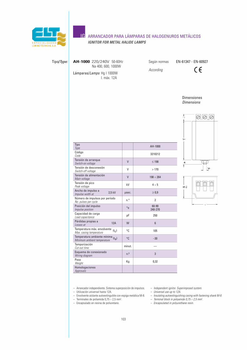
TipoType AH-1000
Tensión de arranqueSwitch-on voltage
Tensión de alimentaciónMain voltage
Ancho de impulso a2,5 kVImpulse width at
Posición del impulsoImpulse position
V
V
µsec.
°e
≤ 198
198 ÷ 264
≥ 0,9
60-90240-270
Pérdidas propias a 12ALosses at W 6
CódigoCode 3210212
Tensión de desconexiónSwitch-off voltage V > 170
Tensión de picoPeak voltage kV 4 ÷ 5
Número de impulsos por períodoNo. pulses per cycle n.° 2
Capacidad de cargaLoad capacitance pF 250
Temperatura máx. envolvente (tc)Max. casing temperature °C 105
TemporizaciónCut-out time minut. ––
PesoWeight Kg 0,32
°C –30
Esquema de conexionadoWiring diagram n.º 3
HomologacionesApprovals
IG ARRANCADOR PARA LÁMPARAS DE HALOGENUROS METÁLICOSIGNITOR FOR METAL HALIDE LAMPS
Tipo/Type:
DimensionesDimensions
Según normas
According
AH-1000 220/240V 50-60HzNa 400, 600, 1000W
Lámparas/Lamps Hg I 1000WI. máx. 12A
EN-61347 - EN-60927
– Arrancador independiente. Sistema superposición de impulsos.– Utilización universal hasta 12A.– Envolvente aislante autoextinguible con espiga metálica M-8.– Terminales de poliamida 0,75 ÷ 2,5 mm2.– Encapsulado en resina de poliuretano.
– Independent ignitor. Superimposed system.– Universal use up to 12A.– Insulating autoextinguishing casing with fastening shank M-8.– Terminal block in polyamide 0,75 ÷ 2,5 mm2.– Encapsulated in polyurethane resin.
103
Temperatura ambiente mínima (ta)Minimum ambient temperature

TipoType AH-2000/220
Tensión de arranqueSwitch-on voltage
Tensión de alimentaciónMain voltage
Ancho de impulso a2,5 kVImpulse width at
Posición del impulsoImpulse position
V
V
µsec.
°e
≤ 198
198 ÷ 264
≥ 0,6
70-90250-270
Pérdidas propias a 18ALosses at W 10
CódigoCode 3210250
Tensión de desconexiónSwitch-off voltage V > 170
Tensión de picoPeak voltage kV 3,5 ÷ 5
Número de impulsos por períodoNo. pulses per cycle n.° 4
Capacidad de cargaLoad capacitance pF 200
Temperatura máx. envolvente (tc)Max. casing temperature °C 90
TemporizaciónCut-out time minut. ––
PesoWeight Kg 1,2
Temperatura ambiente mínima (ta)Minimum ambient temperature °C –30
Esquema de conexionadoWiring diagram n.º 3
HomologacionesApprovals
IG ARRANCADOR PARA LÁMPARAS DE HALOGENUROS METÁLICOSIGNITOR FOR METAL HALIDE LAMPS
Tipo/Type:
DimensionesDimensions
Según normas
According
AH-2000/220 220/240V 50-60Hz
Lámparas/Lamps Hg I. 1000-2000W/220VI. máx. 18A
EN-61347 y EN-60927
– Arrancador independiente. Sistema superposición de impulsos.– Utilización universal hasta 18A.– Envolvente metálico, aluminio extrusionado.– Terminales de poliamida 1,5 ÷ 4 mm2.– Encapsulado en resina de poliuretano.
– Independent ignitor. Superimposed system.– Universal use up to 18A.– Metalic casing in extruded aluminium.– Terminal block in polyamide 1,5 ÷ 4 mm2.– Encapsulated in polyurethane resin.
104
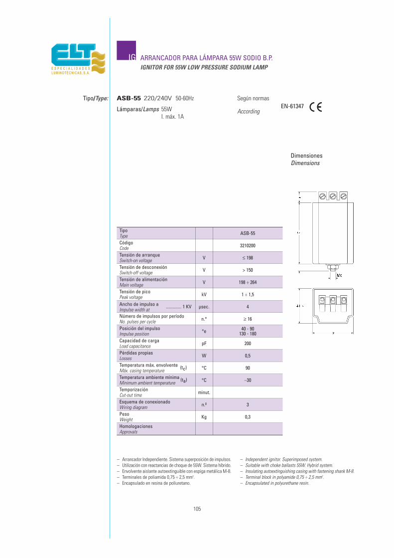
TipoType ASB-55
Tensión de arranqueSwitch-on voltage
Tensión de alimentaciónMain voltage
Ancho de impulso a ................ 1 KVImpulse width at
Posición del impulsoImpulse position
V
V
µsec.
°e
≤ 198
198 ÷ 264
4
40 - 90130 - 180
Pérdidas propiasLosses W 0,5
CódigoCode 3210200
Tensión de desconexiónSwitch-off voltage V > 150
Tensión de picoPeak voltage kV 1 ÷ 1,5
Número de impulsos por períodoNo. pulses per cycle n.° ≥ 16
Capacidad de cargaLoad capacitance pF 200
Temperatura máx. envolvente (tc)Máx. casing temperature °C 90
TemporizaciónCut-out time minut.
PesoWeight Kg 0,3
Temperatura ambiente mínima (ta)Minimum ambient temperature °C –30
Esquema de conexionadoWiring diagram n.º 3
HomologacionesApprovals
IG ARRANCADOR PARA LÁMPARA 55W SODIO B.P. IGNITOR FOR 55W LOW PRESSURE SODIUM LAMP
Tipo/Type:
DimensionesDimensions
Según normas
According
ASB-55 220/240V 50-60Hz
Lámparas/Lamps 55WI. máx. 1A
EN-61347
– Arrancador Independiente. Sistema superposición de impulsos.– Utilización con reactancias de choque de 55W. Sistema híbrido.– Envolvente aislante autoextinguible con espiga metálica M-8.– Terminales de poliamida 0,75 ÷ 2,5 mm2.– Encapsulado en resina de poliuretano.
– Independent ignitor. Superimposed system.– Suitable with choke ballasts 55W. Hybrid system.– Insulating autoextinguishing casing with fastening shank M-8.– Terminal block in polyamide 0,75 ÷ 2,5 mm2.– Encapsulated in polyurethane resin.
105
106

ANEXOANNEX
A
107
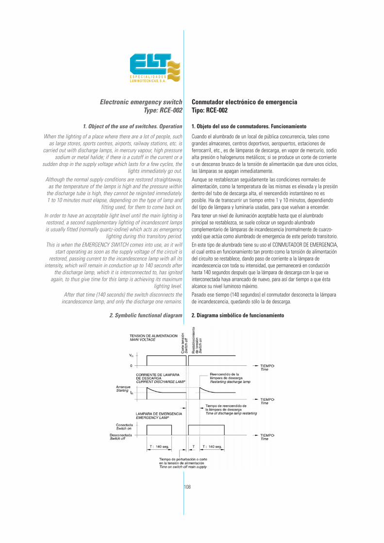
108
Electronic emergency switchType: RCE-002
1. Object of the use of switches. Operation
When the lighting of a place where there are a lot of people, suchas large stores, sports centres, airports, railway stations, etc. is
carried out with discharge lamps, in mercury vapour, high pressuresodium or metal halide; if there is a cutoff in the current or a
sudden drop in the supply voltage which lasts for a few cycles, thelights immediately go out.
Although the normal supply conditions are restored straightaway,as the temperature of the lamps is high and the pressure within
the discharge tube is high, they cannot be reignited immediately. 1 to 10 minutes must elapse, depending on the type of lamp and
fitting used, for them to come back on.In order to have an acceptable light level until the main lighting isrestored, a second supplementary lighting of incandescent lampsis usually fitted (normally quartz-iodine) which acts as emergency
lighting during this transitory period.This is when the EMERGENCY SWITCH comes into use, as it will
start operating as soon as the supply voltage of the circuit isrestored, passing current to the incandescence lamp with all its
intensity, which will remain in conduction up to 140 seconds afterthe discharge lamp, which it is interconnected to, has ignited
again, to thus give time for this lamp is achieving its maximumlighting level.
After that time (140 seconds) the switch disconnects theincandescence lamp, and only the discharge one remains.
2. Symbolic functional diagram
Conmutador electrónico de emergenciaTipo: RCE-002
1. Objeto del uso de conmutadores. Funcionamiento
Cuando el alumbrado de un local de pública concurrencia, tales comograndes almacenes, centros deportivos, aeropuertos, estaciones deferrocarril, etc., es de lámparas de descarga, en vapor de mercurio, sodioalta presión o halogenuros metálicos; si se produce un corte de corrienteo un descenso brusco de la tensión de alimentación que dure unos ciclos,las lámparas se apagan inmediatamente.Aunque se restablezcan seguidamente las condiciones normales dealimentación, como la temperatura de las mismas es elevada y la presióndentro del tubo de descarga alta, el reencendido instantáneo no esposible. Ha de transcurrir un tiempo entre 1 y 10 minutos, dependiendodel tipo de lámpara y luminaria usadas, para que vuelvan a encender.Para tener un nivel de iluminación aceptable hasta que el alumbradoprincipal se restablezca, se suele colocar un segundo alumbradocomplementario de lámparas de incandescencia (normalmente de cuarzo-yodo) que actúa como alumbrado de emergencia de este período transitorio.En este tipo de alumbrado tiene su uso el CONMUTADOR DE EMERGENCIA,el cual entra en funcionamiento tan pronto como la tensión de alimentacióndel circuito se restablece, dando paso de corriente a la lámpara deincandescencia con toda su intensidad, que permanecerá en conducciónhasta 140 segundos después que la lámpara de descarga con la que vainterconectada haya arrancado de nuevo, para así dar tiempo a que éstaalcance su nivel luminoso máximo.Pasado ese tiempo (140 segundos) el conmutador desconecta la lámparade incandescencia, quedando sólo la de descarga.
2. Diagrama simbólico de funcionamiento

109
3. Fitting the switch
The switch and the incandescent lamp are usually installed inthe same fitting, with the discharge lamp and its auxiliary
equipment (ballast, starter and capacitor), but two importantprecautions must be taken:
1. The switch must be placed so that the lamps and theequipment of the discharge lamp heat it as little as possible to
prevent it from reaching high temperatures. It must be as cold aspossible for the internal electronic components to last longer.
2. Make sure that the two lamps do not operate simultaneouslylonger than the time assigned. This would cause strong rises in
temperature endangering the fitting and all its components.
4. Connection circuit
5. Technical characteristics
Rated operation voltage: 220V ± 10% 50/60Hz.Minimum operating voltage: 175V.
Maximum power of the emergency lamp: 250W. (1A).Maximum intensity in the main lamp circuit: 12A.
Own power consumed:Main lamp operating: 1W.
Emergency lamp operating: 1,8W.Operating time after ignition of lamp: 140 seconds.
Maximum temperature in casing: 90°C.
6. Constructions and physical dimensions
Made with self-extinguishing insulating casing.Connection system by means of four polyamide
wire clamps for cables with section up to 2,5 mm2,secured with screws.
All the components are encapsulated inpolyurethane resins to prevent damp from
penetrating.
3. Colocación del conmutador
El conmutador y la lámpara de incandescencia suelen ser instalados en lamisma luminaria, con lámpara de descarga y su equipo auxiliar(reactancia, arrancador y condensador), pero se debe tomar dosprecauciones importantes:1. El conmutador debe estar colocado de forma que las lámparas y elequipo de la descarga le aporten el mínimo calor y evitar que alcancetemperaturas altas. Debe estar lo más frío posible para mayor duración delos componentes electrónicos internos.2. Asegurarse de que no funcionan más del tiempo asignado las doslámparas simultáneamente. Ello ocasionaría fuertes elevaciones detemperatura con peligro para la luminaria y todos sus componentes.
4. Circuito de conexión
5. Características eléctricas
Tensión nominal de funcionamiento: 220V ± 10% 50/60Hz.Tensión mínima de funcionamiento: 175V.Potencia máxima de la lámpara de emergencia: 1.000W. (4A).Intensidad máxima en el circuito de lámpara principal: 12A.
Potencia propia consumida:Funcionando la lámpara principal: 1W.Funcionando la lámpara de emergencia: 1,8W.Tiempo de funcionamiento tras el encendido de la lámpara:140 segundos.Temperatura máxima en el envolvente: 90°C.
6. Construcción y dimensiones físicas
Construido con envolvente aislante autoextinguible.Sistema de conexión mediante cuatro clemas de poliamida,para cables de sección hasta 2,5 mm2, con fijación contornillo.Todos los componentes van encapsulados en resinas depoliuretano para evitar la penetración de humedad.
DimensionesDimmensions

A ESQUEMAS DE CONEXIONADO
Importante: Sobre todos estos esquemas siempre prevalece el esquema marcado en la reactanciaImportant: Between all these diagrams, it will always prevail the diagram shown on the ballast.
110
WIRING DIAGRAMS

111
A ESQUEMAS DE CONEXIONADOWIRING DIAGRAMS
Importante: Sobre todos estos esquemas siempre prevalece el esquema marcado en la reactanciaImportant: Between all these diagrams, it will always prevail the diagram shown on the ballast.
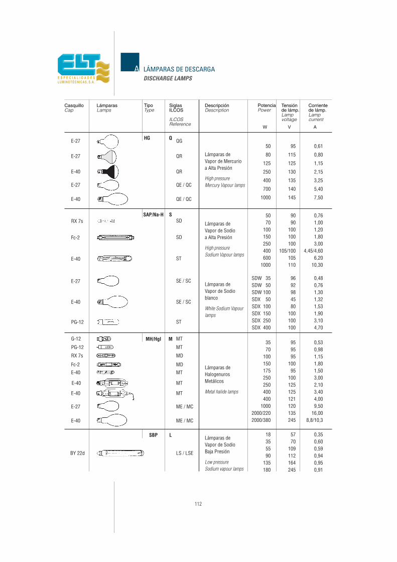
112
A LÁMPARAS DE DESCARGADISCHARGE LAMPS
Lámparas Tipo Descripción Potencia Tensiónde lámp.
Corrientede lámp.
SiglasILCOS
Casquillo
W V A

113
220/230/240Vapor de MercurioMercury vapour lamps
50
80
125
400
1000
70
150
400
1000
70
150
250
1000
2000
2000
250
700
50
100
250
600
35
100
250
400
1000
2000
3500
0,61
0,80
7
8
6
7
9
15
24
40
50
7,5
10
11
17
28
40
55
85
5
10
11
17
15
28
30
60
75
100
32
50
85
10
18
28
45
60
9
12
13
20
32
45
65
100
6
12
13
20
18
32
36
72
85
125
37
60
100
1,15
3,25
7,50
1
1,80
4,45
10,30
1
1,80
3
8,25
16,50
10,30
2,15
5,40
0,76
1,20
3
6,20
0,53
1,10
2,10
3,50
9,50
8,80
18,00
LámparaLamp
Capacidad para λ : 0,90+0,05
Capacity for λ : 0,90+0,05
TipoType
PotenciaPower
W
CorrienteCurrent
A
TensiónVoltage
V
50Hz
µF ± 5%
60Hz
µF ± 5%
A CAPACIDADES PARA CORREGIR EL FACTOR DE POTENCIACAPACITIES FOR POWER FACTOR CORRECTION
220/230/240Vapor de Sodio APHigh-pressuresodium vapour lamps
HalogenurosMetálicosMetal halide lamps
220/230/240
380/400/415
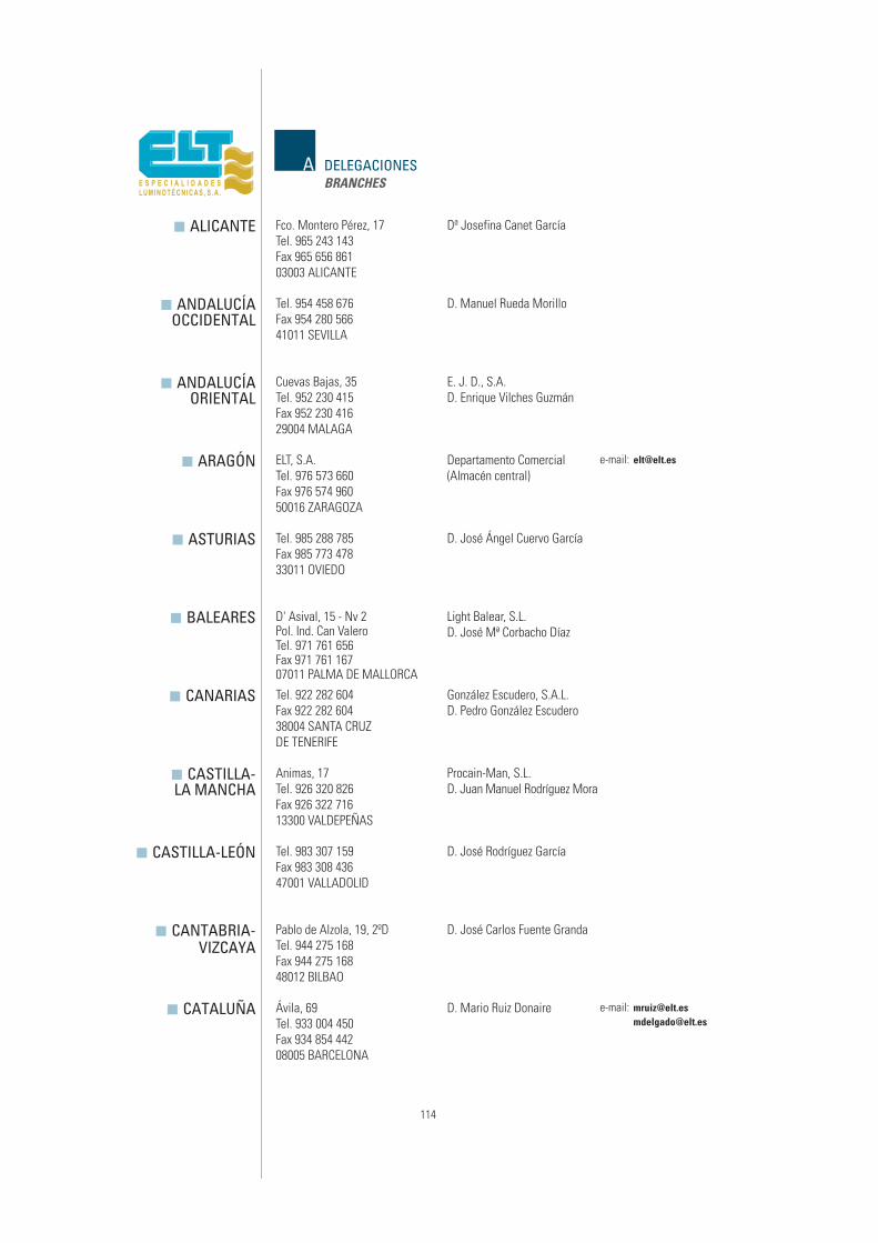
A DELEGACIONESBRANCHES
� ALICANTE
� ANDALUCÍAOCCIDENTAL
� ANDALUCÍAORIENTAL
� ARAGÓN
� ASTURIAS
� BALEARES
� CANARIAS
� CASTILLA-LA MANCHA
� CASTILLA-LEÓN
� CANTABRIA-VIZCAYA
� CATALUÑA
Fco. Montero Pérez, 17Tel. 965 243 143Fax 965 656 86103003 ALICANTE
Dª Josefina Canet García
Tel. 954 458 676Fax 954 280 56641011 SEVILLA
D. Manuel Rueda Morillo
Cuevas Bajas, 35Tel. 952 230 415Fax 952 230 41629004 MALAGA
E. J. D., S.A.D. Enrique Vilches Guzmán
ELT, S.A.Tel. 976 573 660Fax 976 574 96050016 ZARAGOZA
Departamento Comercial(Almacén central)
e-mail: [email protected]
Tel. 985 288 785Fax 985 773 47833011 OVIEDO
D. José Ángel Cuervo García
D' Asival, 15 - Nv 2Pol. Ind. Can ValeroTel. 971 761 656Fax 971 761 16707011 PALMA DE MALLORCA
Light Balear, S.L.D. José Mª Corbacho Díaz
Tel. 922 282 604Fax 922 282 60438004 SANTA CRUZDE TENERIFE
González Escudero, S.A.L.D. Pedro González Escudero
Animas, 17Tel. 926 320 826Fax 926 322 71613300 VALDEPEÑAS
Procain-Man, S.L.D. Juan Manuel Rodríguez Mora
Tel. 983 307 159Fax 983 308 43647001 VALLADOLID
D. José Rodríguez García
Pablo de Alzola, 19, 2ºDTel. 944 275 168Fax 944 275 16848012 BILBAO
D. José Carlos Fuente Granda
Ávila, 69Tel. 933 004 450Fax 934 854 44208005 BARCELONA
D. Mario Ruiz Donaire e-mail: [email protected]@elt.es
114
ADELEGACIONESBRANCHES
EXTREMADURA �García Paredes, 19, L-1Tel. 924 275 405Fax 924 275 40506006 BADAJOZ
Distrel Extremeña, S.L.D. Andrés Granero Guisado
GALICIA �Tel. 981 224 622Fax 981 224 622
LA CORUÑA
D. Alfonso Martín Serrano Sastre
GUIPÚZCOA �Tel. 943 217 095Fax 943 217 095
20009 SAN SEBASTIAN
D. José Mª Benavente Garasa
JAÉN �Pol. Los Olivares, Huelma, 9-10Tel. 953 280 677Fax 953 280 537
23009 JAEN
D. José Ballesta Ramos
LA RIOJA-NAVARRA �Tel. 948 340 672Fax 948 340 944
PUENTE LA REINA (Navarra)
D. Carmelo Ulzurrum Soto
MADRID �Tel. 917 678 721Fax 917 678 72228033 MADRID
D. Manuel de la Torre VélezD. Alfredo Martín Vicente
MURCIA �Pº Virgen Fuensanta, 4 - La FlotaTel. 968 244 046Fax 968 247 95230008 MURCIA
ElectrorrepresentacionesRuiz-Manzano
D. Francisco Ruiz Barceló
VALENCIA- �CASTELLÓN
Isla Cabrera, 6Tel. 963 332 440Fax 963 332 527
46026 VALENCIA
LoymarD. Javier López
D. Juan Martínez
VITORIA �Avda. Sancho El Sabio, 18Tel. 945 223 120Fax 945 226 23101008 VITORIA
Representaciones AnsoteguiDª Amaia Ansotegui Garagarza
e-mail: [email protected]
115

A REPRESENTANTESAGENTS
■ DINAMARCA Hojnaesvej, 44 ELTHERMO SEARCHLIGHT A/SDENMARK Tel. 453 672 22 00
Fax 453 641 07 412610 RODOVRE
■ FRANCIA 38, Rue Adrien Damalix ABAKFRANCE Tel. 01 43 53 20 00
Fax 01 48 93 41 5394410 SAINT MAURICE
■ GRECIA 27, Danaidon Str. ILECTREL LTD.GREECE Tel. 010/682 60 51
Fax 010/680 03 1415232 HALANDRI - ATHENS
■ ITALIA V/ Della Loggetta, 115 ASCOITALY Tel. 055 674 076 TOSCANA
Fax 055 673 19450135 FIRENZE
Stanis Manca, 22 BROZZU CLAUDIOTel. 079 295 415 CERDEÑAFax 079 295 4157100 SASSARI-CERDEÑA
Via Regina Margherita, 133 C.M.C.Tel. 073 368 8304 MARCHE E UMBRIAFax 073 368 616962016 PORTO POTENZA PICENA (MC)
Via Magenta, nr. 77/22 ELPROM, S.R.L.Tel. 02 931 80 210 LOMBARDIAFax 02 935 07 68820017 Rho MILANO
Via delle Libellule, 42 TRILUCETel. 06 505 24 260 LAZIOFax 06 505 13 61700143 ROMA
■ JORDANIA P.O. Box: 7088 AL-AZZAH TRADING AGENCYJORDAN Tel. 6 464 82 39
Fax 6 463 72 3911118 AMMAN
■ REINO UNIDO 13 Gateway Trading Estate PRIME LIGHTUNITED KINGDOM Hythe road ELECTRICAL LTD.
Tel. 208 968 2000Fax 208 968 2020LONDON NW10 6RJ
■ SRI LANKA 25/14. 6th Lane D.L.E. WANIGASOORIYASRI LANKA Tel. 64 60 55
Fax 44 55 59RAWATAWATTA - MORATUWA
e-mail: [email protected]
e-mail: [email protected]
e-mail: [email protected]
e-mail: [email protected]
e-mail: [email protected]
e-mail: [email protected]
e-mail: [email protected]
e-mail: [email protected]
e-mail: [email protected]
116
AREPRESENTANTESAGENTS
ELEKTRIK D&S Rruga Sami Frasheri, ALBANIA ■Ph.9 Shk.6 Ap.46 ALBANIA
Tel. / Fax 355 424 35 33TIRANA
ELT ARGENTINA, S.A. Cochabamba, 881 ARGENTINA ■Área: Sudamérica Villa Martelli ARGENTINA
Tel. 541 147 09 1111Fax 541 147 09 6666
B1603BKQ BUENOS AIRES
MIRABELLA Mirabella Drive AUSTRALIA ■INTERNATIONAL PTY. LTD. Tel. (3) 9335 3633 AUSTRALIA
Fax (3) 9335 4300TULLAMARINE - 3043 VICTORIA
CHEMICO CORPORATION 48/11 Motijheel C/A (4Th Floor) BANGLADESH ■Tel. 02/955 0875 BANGLADESH
Fax 402/956 5038DHAKA 1000
AMBIENTE LTD. Plachkovski Manastir 21A BULGARIA ■Tel. 35 9 29 625 524 BULGARIAFax 35 9 29 621 267
SOFIA
SUFFICE INDUSTRIAL Flat H, 7/Fl., World Tech Centre CHINA ■TECNOLOGY LIMITED 95 How Ming Street, Kwun Tong CHINA
Headoffice-Area in charge: Hong Kong Tel. 852 2343 7563Fax 852 2797 8115
KOWLOON. HONG KONG
SUFFICE WAREHOUSE Room 605, Wang Cheng(Shenzhen) Warehouse Transportation Bldg.
Headoffice-Area in charge: Shenzhen 6# HongMian Road,Futian Free trade ZoneTel. 86 755 8359 3381Fax 86 755 8359 3400
Zip 518038 SHENZHEN. CHINA
GUANGZHOU OFFICE Room 2111, Yian PlazaArea in charge: Southern part of China NO. 33, Jian She Liu Rd.
Tel. 86 20 8363 35 45Fax 86 20 8363 36 37
Zip 510060 GUANGZHOU. CHINA
SUFFICE INTERNATIONAL RM 1401, No. 45aTRADING (Shanghai) LTD. North CaoxiRd.
Area in charge: East, Middle and West territory of China Tel. 86 21 6468 2012Fax 86 21 6474 8667
Zip 200030 SHANGHAI. CHINA
BEIJING OFFICE RM 911, Huashang Bldg., No.2Area in charge: North territory of China Yanjing xili, Chaoyang District
Tel. 86 10 6594 9269Fax 86 10 6594 9778
Zip 100025 BEIJING. CHINA
e-mail: [email protected]
e-mail: [email protected]
e-mail: [email protected]
e-mail: [email protected]
e-mail: [email protected]
e-mail: [email protected]
e-mail: [email protected]
e-mail: [email protected]
e-mail: [email protected]
117

A DISTRIBUIDORESDISTRIBUTORS
■ CROACIA Barciceva, 8 NEON CENTAR D.O.O.CROATIA Tel. 385 1 4553 901
Fax 385 1 4622 93410000 ZAGREB
■ EGIPTO 15 Emad ElDine St. NASSIB TORCOMEGYPT Tel. 591 18 00 TAWACOL N.T.T.
Fax 592 78 4311511 CAIRO
■ ESLOVAQUIA Y Kollarova, 5 TRICOMREP. CHECA Tel. 245 923 147
SLOVAKIA AND Fax 245 923 147CZECH REP. 90301 SENEC
■ FINLANDIA Unkarinkatu 10 ARRANT-LIGHT OYFINLAND Tel. 02 246 23 00
Fax 02 246 23 0120750 TURKU
■ ISRAEL Histadrut Ave, 180, Ind. Centre H.M. SCHÖNGUT LTD.ISRAEL Tel. 4 872 21 56
Fax 4 872 25 63P.O.B. 10023 - HAIFA BAY 26110
■ LÍBANO Tel. 03 - 224 404 BAHIJ ISMAIL EST. FORLEBANON Fax 03 - 596 041 EXTERNAL TRADE
05 - 304 06005 - 300 776GHARIFEH - EL SHOUF
■ MARRUECOS 35, Rue Socrate - Maarif PROMELEC S.A.MOROCCO Tel. 225 97 23
Fax 225 10 8102 CASABLANCA
■ PAKISTAN 1 St. Fl., Mughal Electric HKB POWER ENGINEERINGPAKISTAN Market.Azeem Str, 10 COMPANY
Nishtar Rd., LahoreTel. 42/765 2237Fax 42/766 573754000 PAKISTAN
e-mail: [email protected]
e-mail: [email protected]
e-mail: [email protected]
e-mail: [email protected]
e-mail: [email protected]
e-mail: [email protected]
118

ADISTRIBUIDORESDISTRIBUTORS
BMK CENTRUM Sp. Z.O.O. ul. Azotowa 21 POLONIA ■Tel. 032 245 90 74 POLANDFax 032 245 91 7441-503 CHORZÓW
ELECTRO SILUZ Estrada int. PORTUGAL ■da circunvalaçao, 5139/5157 PORTUGAL
Tel. 351 225 420 350Fax 351 225 401 208
4300 PORTO
DANIKOR LTD. Okrujnoy Proezd, 16, office 500 RUSIA ■Tel. (095) 514 66 56 RUSSIAFax (095) 369 43 83
105187 MOSCOW
MINEL-SCHREDER Tosin Bunar, 51 SERBIA Y ■FABRIKA SVETILJKI Tel. 381 112 100 933 MONTENEGRO
Tel. 351 225 420 350 SERBIA ANDFax 381 112 612 166 MONTENEGRO
11080 BELGRADE-ZEMUN
KUM ENG HUAT NO.4 Kaki Bukit Place SINGAPUR ■ELECTRIC, CO. (Eunos Techpark) SINGAPORE
Tel. 65 6842 18 18Fax 65 6841 28 28
416182 SINGAPORE
URANUS LIGHTING CO. MARJEH SQ. RAMIST SIRIA ■SIOUFI BLD. SYRIA
Tel. 245 4882Fax 245 3223DAMASCUS
GROUPE D’ECLAIRAGE Z. I. Ben Arous TÚNEZ ■DE TUNISIE Tel. 380 525 TUNISIA
G.E.T. Fax 380 6602013 TUNIS
VATRA-SCHREDER Ul. Mikulinetskaya, 46B UCRANIA ■Tel. 380 352 25 49 58 UCRANIAFax 380 352 25 59 53
82001 TERNOPOL-UCRANIA
e-mail: [email protected]
e-mail: [email protected]
e-mail: [email protected]
e-mail: [email protected]
e-mail: [email protected]
e-mail: [email protected]
e-mail: [email protected]
119
descarga