Business Process Modelling - Πανεπιστήμιο...
36
Lecture 2 Business Process Modelling 17/02/2020 CS 565 - LECTURE 2 CS565 - Business Process & Workflow Management Systems
Transcript of Business Process Modelling - Πανεπιστήμιο...
Lecture 2
Business Process Modelling
17/02/2020CS 565 - LECTURE 2
CS565 - Business Process & Workflow Management Systems
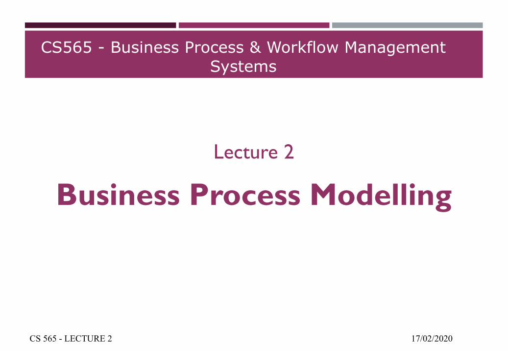
BUSINESS PROCESS LIFECYCLE
17/02/2020CS 565 - LECTURE 2
Evaluation:Process mining
Analytics/Warehousing
Enactment:OperationMonitoring
Maintenance
Configuration:System selectionImplementation
Test & Deployment
Design:Business Process Identification &
Modelling
Analysis:ValidationSimulationVerification
Administration &
Stakeholders
BUSINESS PROCESS MODELLING
¡ The model of a BP can be described via a specific language and be specified through BP modelling tools (part of a BPMS)
¡ Can be performed at different levels:
¡ Organizational (coarse-grained, textual forms)
¡ Operational (fine-grained, semi-structured/formal models)
¡ Explicit representation:
¡ Usually through graphical notations
¡ Ideal for internal communication between stakeholders -> flexibility
17/02/2020CS 565 - LECTURE 2
BUSINESS PROCESS MODELLING
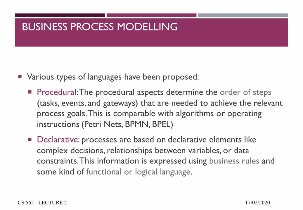
¡ Various types of languages have been proposed:
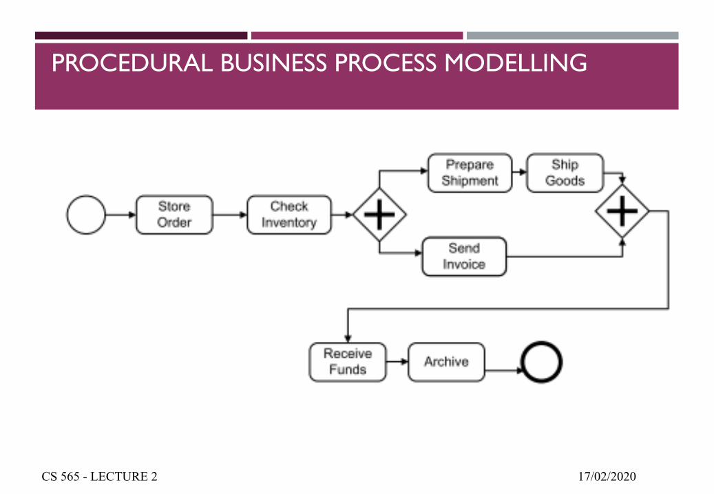
¡ Procedural: The procedural aspects determine the order of steps (tasks, events, and gateways) that are needed to achieve the relevant process goals. This is comparable with algorithms or operating instructions (Petri Nets, BPMN, BPEL)
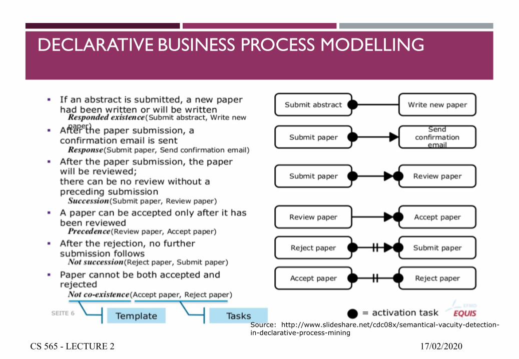
¡ Declarative: processes are based on declarative elements like complex decisions, relationships between variables, or data constraints. This information is expressed using business rules and some kind of functional or logical language.
17/02/2020CS 565 - LECTURE 2
PROCEDURAL BUSINESS PROCESS MODELLING
17/02/2020CS 565 - LECTURE 2
DECLARATIVE BUSINESS PROCESS MODELLING
17/02/2020CS 565 - LECTURE 2
Source: http://www.slideshare.net/cdc08x/semantical-vacuity-detection-in-declarative-process-mining
DECLARATIVE BUSINESS PROCESS MODELLING
17/02/2020CS 565 - LECTURE 2
DECLARATIVE BUSINESS PROCESS MODELLING
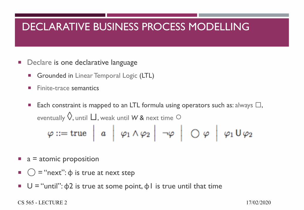
¡ Declare is one declarative language
¡ Grounded in Linear Temporal Logic (LTL)
¡ Finite-trace semantics
¡ Each constraint is mapped to an LTL formula using operators such as: always □,
eventually ◊, until ⊔, weak until W & next time ○
¡ a = atomic proposition
¡ ◯ = “next”: φ is true at next step
¡ U = “until”: φ2 is true at some point, φ1 is true until that time
17/02/2020CS 565 - LECTURE 2
LTL: RESTAURANT EXAMPLE
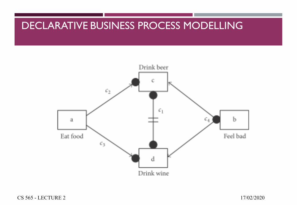
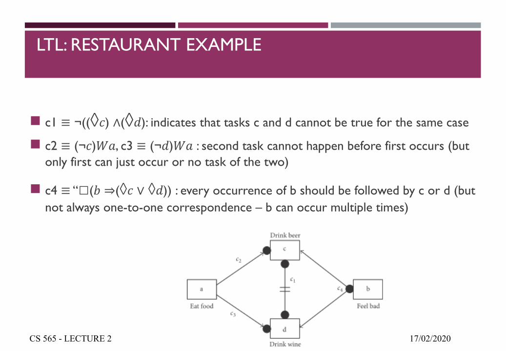
g c1 ≡ ¬((◊") ∧(◊$): indicates that tasks c and d cannot be true for the same case
g c2 ≡ (¬")%&, c3 ≡ (¬$)%& : second task cannot happen before first occurs (but only first can just occur or no task of the two)
g c4 ≡ “□(' ⇒(◊" ∨ ◊$)) : every occurrence of b should be followed by c or d (but not always one-to-one correspondence – b can occur multiple times)
17/02/2020CS 565 - LECTURE 2
LTL: TRAFFIC LIGHT EXAMPLE
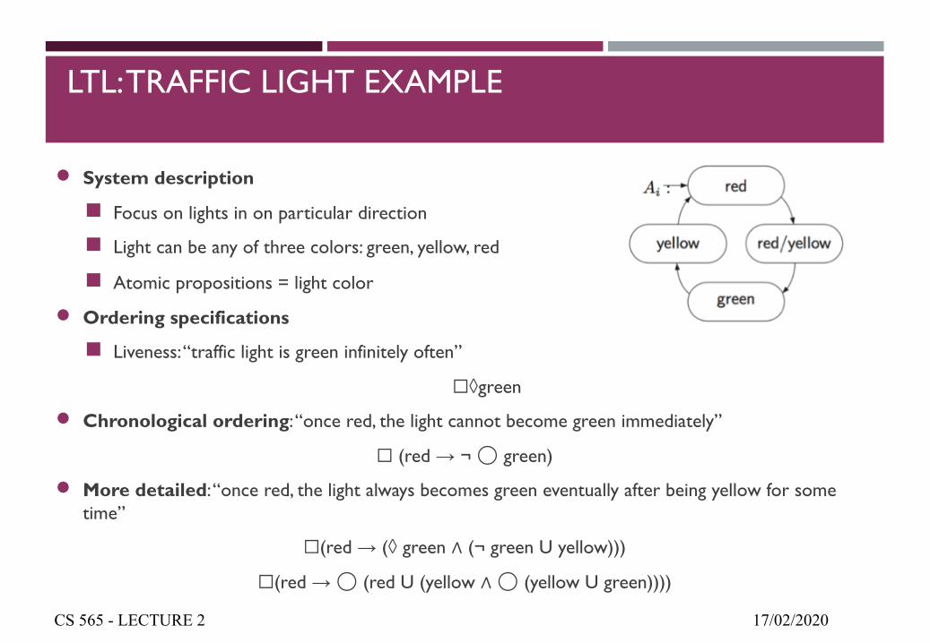
n System description
g Focus on lights in on particular direction
g Light can be any of three colors: green, yellow, red
g Atomic propositions = light color
n Ordering specifications
g Liveness: “traffic light is green infinitely often”
☐◊green
n Chronological ordering: “once red, the light cannot become green immediately”
☐ (red → ¬ ◯ green)
n More detailed: “once red, the light always becomes green eventually after being yellow for some time”
☐(red → (◊ green ∧ (¬ green U yellow)))
☐(red →◯ (red U (yellow ∧◯ (yellow U green))))
17/02/2020CS 565 - LECTURE 2
FORMAL BUSINESS PROCESS LANGUAGES
¡ Have unambiguous semantics
¡ Allow for BP analysis
¡ Require some expertise in Mathematics or Computer Science (wrt the formalism used)
¡ Abstract from implementation details
¡ Different formalisms have been employed:¡ Markov Chains, Queuing Networks, Turing Machines, Transition Systems, Petri Nets,
Temporal Logic and Process Algebras
17/02/2020CS 565 - LECTURE 2
CONCEPTUAL BUSINESS PROCESS LANGUAGES
¡ More comprehensive & easy to use
¡ Do not have well-defined semantics
¡ Do not allow for analysis
¡ The respective specifications cannot be executed
¡ Approximate description of the desired behaviour
¡ Examples: Business Process Modelling Notation (BPMN), Event-Driven Process Chains (EPCs), UML Activity diagrams
17/02/2020CS 565 - LECTURE 2
BUSINESS PROCESS EXECUTION LANGUAGES
¡ Workflow-based languages
¡ Provide the appropriate level of detail for making specifications executable
¡ Precise definition of the desired behaviour
¡ Example: BPEL
17/02/2020CS 565 - LECTURE 2
FLOW CHARTS
¡ Formalised graphic representation of a program/work logic sequence
¡ Sequential flow of actions with no activity breakdown
¡ Characteristics:
¡ Flexibility (various ways for process description)
¡ Easy to use – perfect for communication
¡ Drawbacks:
¡ Process boundaries may not be clear
¡ Tend to be very big
¡ No difference between main & sub-activities
¡ Hard to navigate (no sub-layers)
17/02/2020CS 565 - LECTURE 2
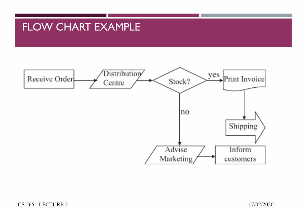
FLOW CHART EXAMPLE
17/02/2020CS 565 - LECTURE 2
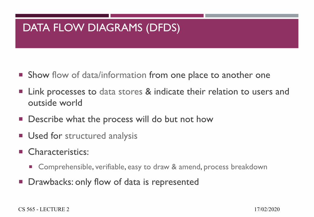
DATA FLOW DIAGRAMS (DFDS)
¡ Show flow of data/information from one place to another one
¡ Link processes to data stores & indicate their relation to users and outside world
¡ Describe what the process will do but not how
¡ Used for structured analysis
¡ Characteristics:¡ Comprehensible, verifiable, easy to draw & amend, process breakdown
¡ Drawbacks: only flow of data is represented
17/02/2020CS 565 - LECTURE 2
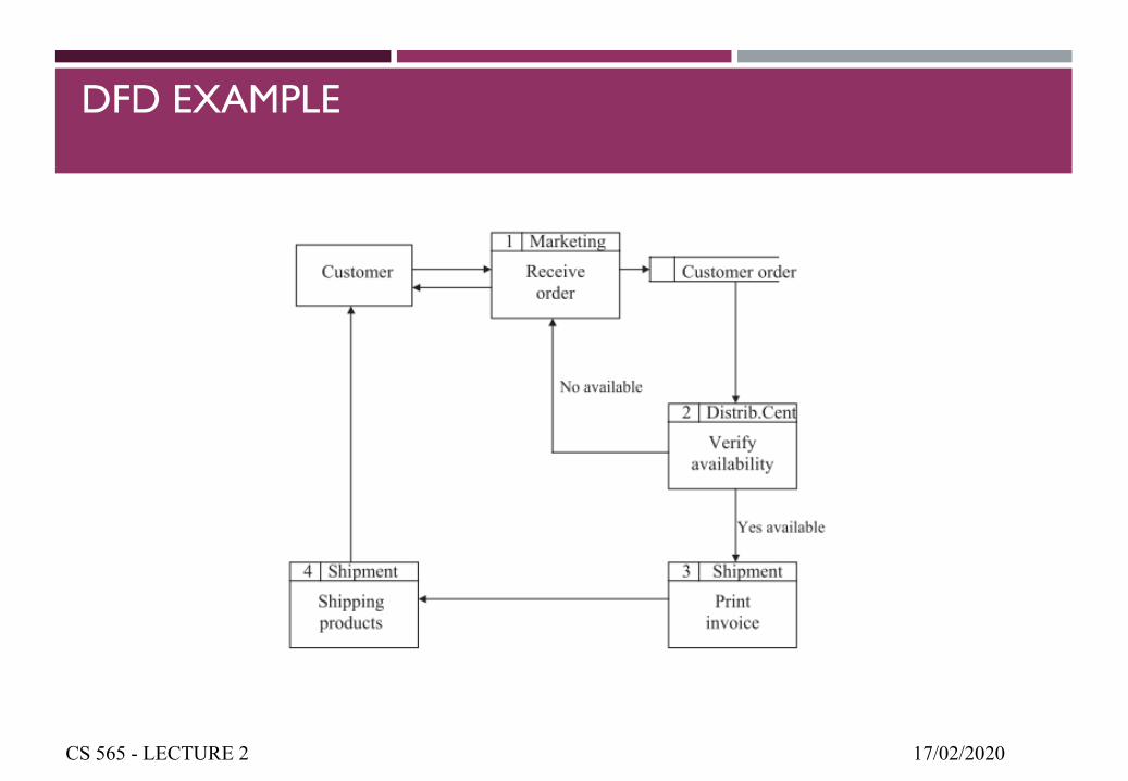
DFD EXAMPLE
17/02/2020CS 565 - LECTURE 2
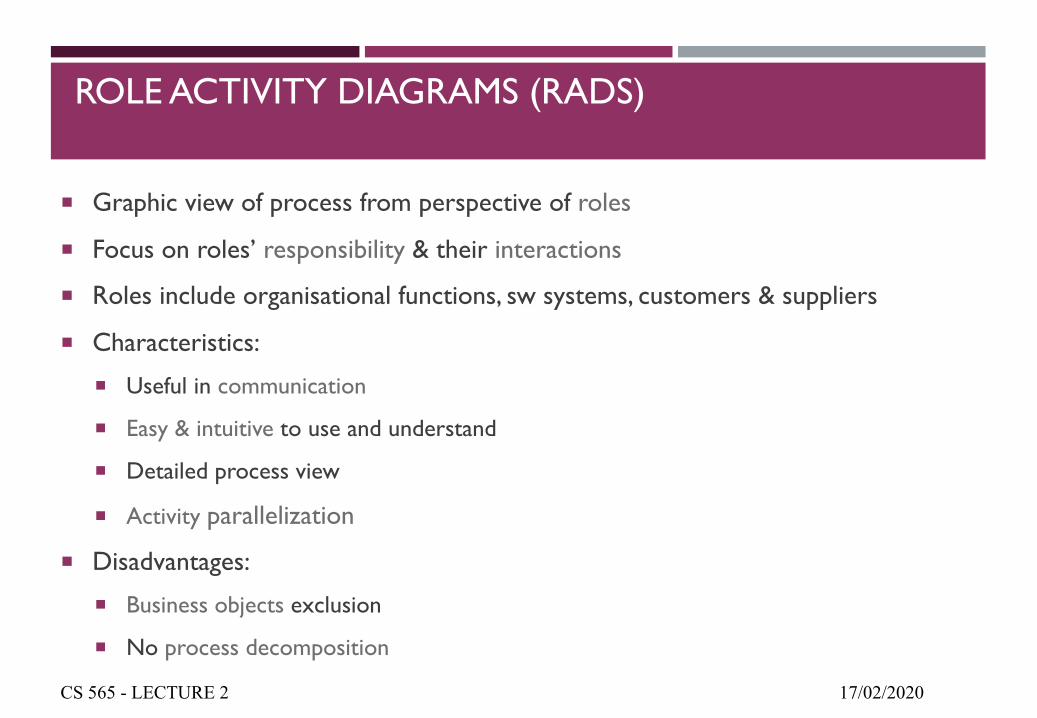
ROLE ACTIVITY DIAGRAMS (RADS)
¡ Graphic view of process from perspective of roles
¡ Focus on roles’ responsibility & their interactions
¡ Roles include organisational functions, sw systems, customers & suppliers
¡ Characteristics:
¡ Useful in communication
¡ Easy & intuitive to use and understand
¡ Detailed process view
¡ Activity parallelization
¡ Disadvantages:
¡ Business objects exclusion
¡ No process decomposition
17/02/2020CS 565 - LECTURE 2
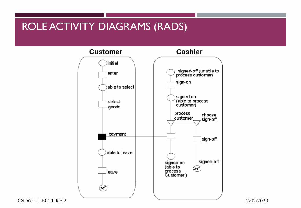
ROLE ACTIVITY DIAGRAMS (RADS)
17/02/2020CS 565 - LECTURE 2
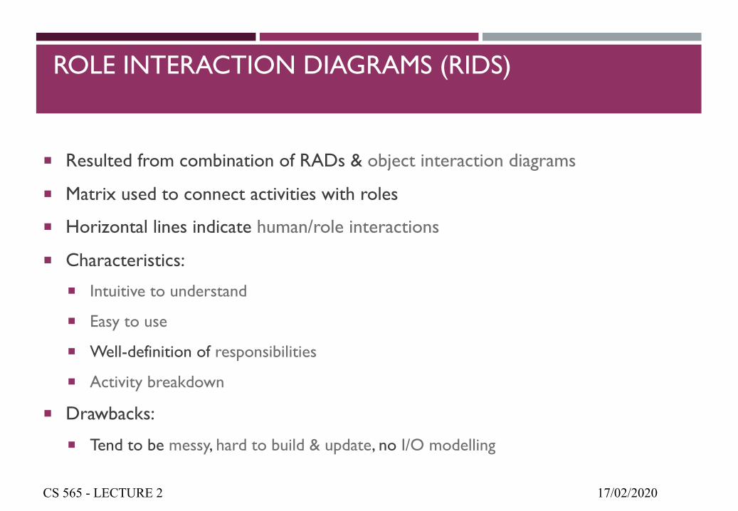
ROLE INTERACTION DIAGRAMS (RIDS)
¡ Resulted from combination of RADs & object interaction diagrams
¡ Matrix used to connect activities with roles
¡ Horizontal lines indicate human/role interactions
¡ Characteristics:
¡ Intuitive to understand
¡ Easy to use
¡ Well-definition of responsibilities
¡ Activity breakdown
¡ Drawbacks:
¡ Tend to be messy, hard to build & update, no I/O modelling
17/02/2020CS 565 - LECTURE 2
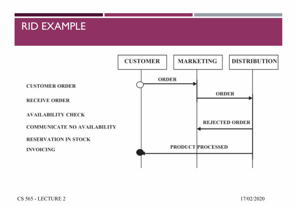
RID EXAMPLE
17/02/2020CS 565 - LECTURE 2
UNIFIED MODELLING LANGUAGE (UML) DIAGRAMS
¡ Object-oriented methods used for modelling
¡ Collection of engineering practices proven successful for large & complex system modelling
¡ Covers both conceptual (BPs & system functions) & concrete elements (programming language classes, DB schemas, sw components)
¡ UML diagrams:
¡ Class diagram: system structure (concepts & relations)
¡ Statechart diagram: states of a class or system
¡ Activity diagram: activities and actions
¡ Sequence diagram: messages sent between set of objects
¡ Collaboration diagram: complete collaboration between objects
17/02/2020CS 565 - LECTURE 2
UML CLASS DIAGRAMS
17/02/2020CS 565 - LECTURE 2
n UML class diagram: a picture of the classes in an OO system, their fields and methods, and connections between the classes that interact or inherit from each other
n details of how the classes interact with each othern algorithmic details; how a particular behavior is implemented
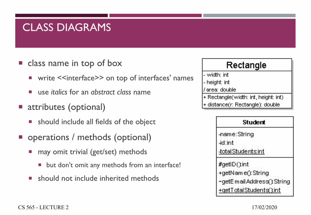
CLASS DIAGRAMS
¡ class name in top of box¡ write <<interface>> on top of interfaces' names
¡ use italics for an abstract class name
¡ attributes (optional)¡ should include all fields of the object
¡ operations / methods (optional)¡ may omit trivial (get/set) methods
¡ but don't omit any methods from an interface!
¡ should not include inherited methods
17/02/2020CS 565 - LECTURE 2
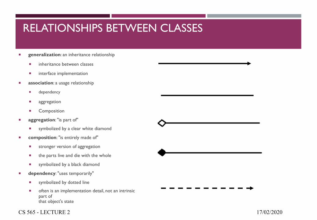
RELATIONSHIPS BETWEEN CLASSES
¡ generalization: an inheritance relationship
¡ inheritance between classes
¡ interface implementation
¡ association: a usage relationship
¡ dependency
¡ aggregation
¡ Composition
¡ aggregation: "is part of"
¡ symbolized by a clear white diamond
¡ composition: "is entirely made of"
¡ stronger version of aggregation
¡ the parts live and die with the whole
¡ symbolized by a black diamond
¡ dependency: "uses temporarily"
¡ symbolized by dotted line
¡ often is an implementation detail, not an intrinsic part ofthat object's state
17/02/2020CS 565 - LECTURE 2
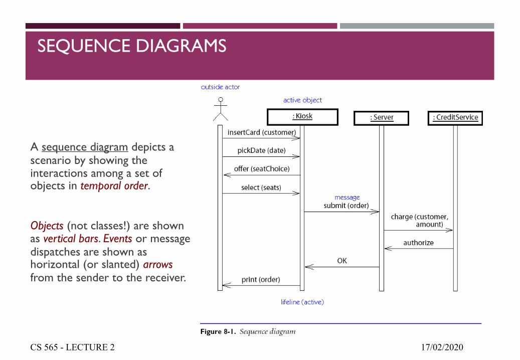
SEQUENCE DIAGRAMS
A sequence diagram depicts a scenario by showing the interactions among a set of objects in temporal order.
Objects (not classes!) are shown as vertical bars. Events or message dispatches are shown as horizontal (or slanted) arrowsfrom the sender to the receiver.
17/02/2020CS 565 - LECTURE 2
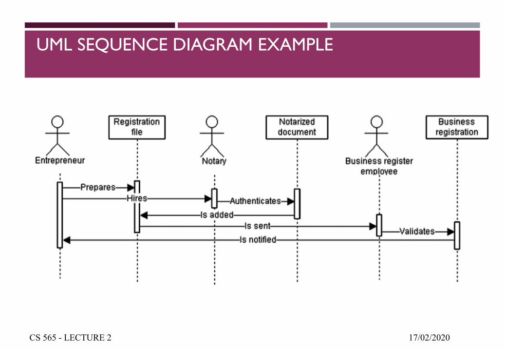
UML SEQUENCE DIAGRAM EXAMPLE
17/02/2020CS 565 - LECTURE 2
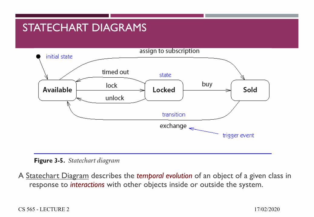
STATECHART DIAGRAMS
A Statechart Diagram describes the temporal evolution of an object of a given class in response to interactions with other objects inside or outside the system.
17/02/2020CS 565 - LECTURE 2
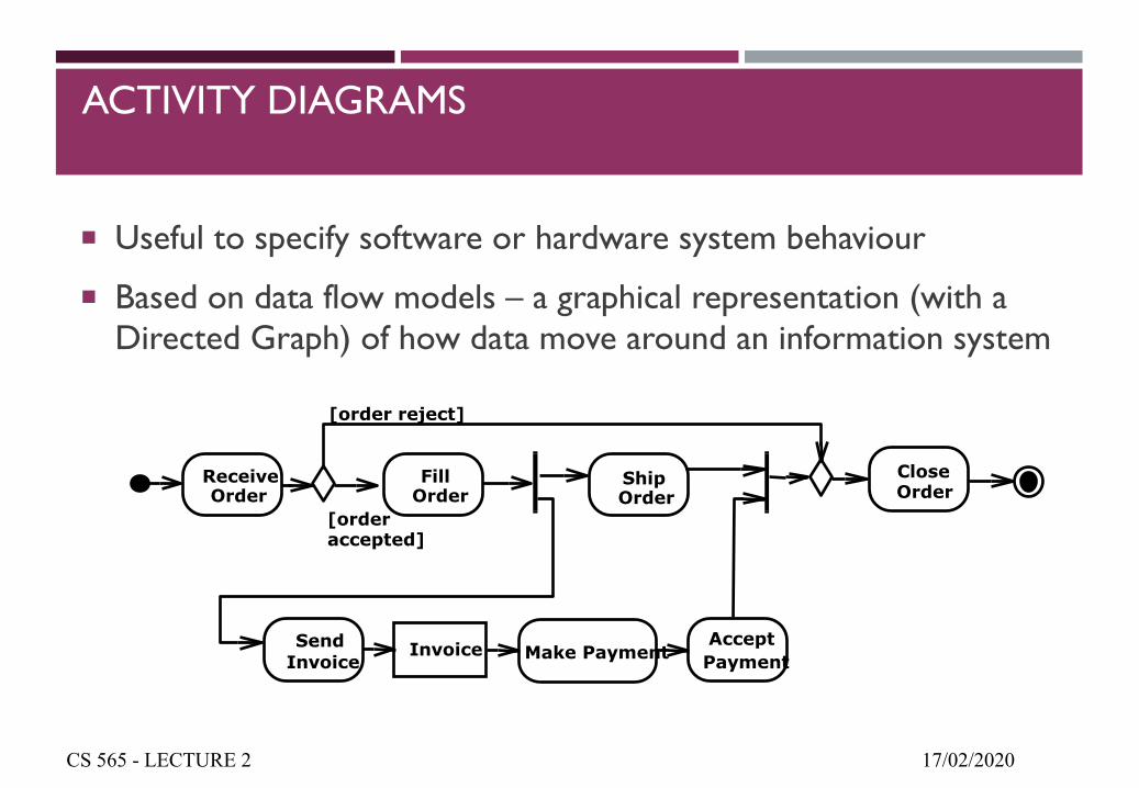
ACTIVITY DIAGRAMS
¡ Useful to specify software or hardware system behaviour
¡ Based on data flow models – a graphical representation (with a Directed Graph) of how data move around an information system
17/02/2020CS 565 - LECTURE 2
FillOrder
ShipOrder
SendInvoice
AcceptPayment
CloseOrder
Make Payment
[orderaccepted]
Invoice
ReceiveOrder
[order reject]
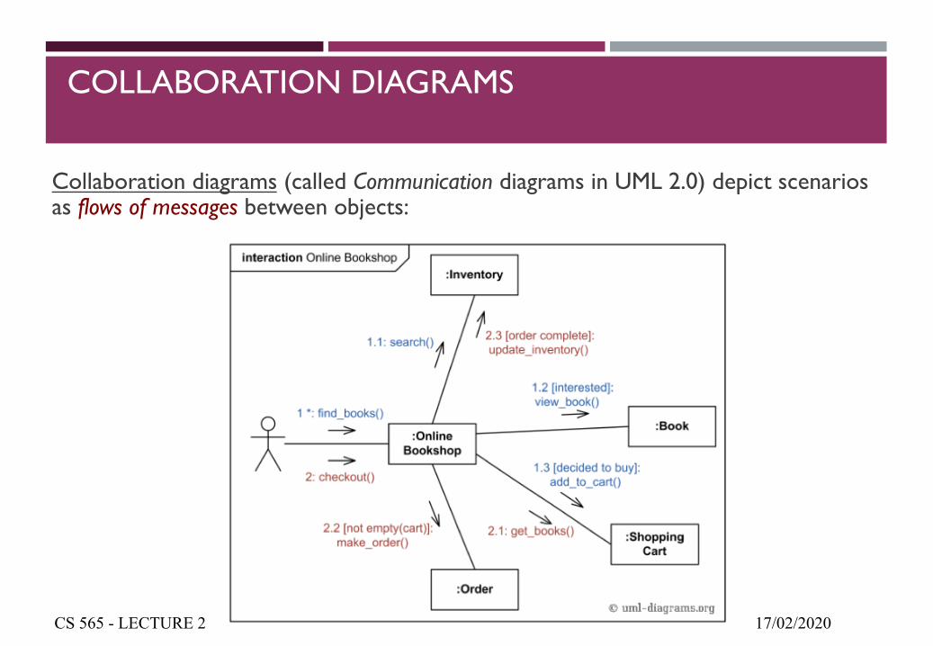
COLLABORATION DIAGRAMS
Collaboration diagrams (called Communication diagrams in UML 2.0) depict scenarios as flows of messages between objects:
17/02/2020CS 565 - LECTURE 2
EVENT PROCESS CHAINS (EPCS)
¡ Informal notation for representing domain concepts & processes
¡ Not focused on technical realization
¡ Part of a holistic modelling approach called the ARIS framework
¡ Main building blocks: events, functions (low-level of granularity), connectors(process logic) & control flow edges
¡ Framework also includes interaction flow diagrams (high-level view of organisational entities & their interactions) & function flow diagrams (refinement of interaction flow diagrams with interaction ordering & interaction representation via coarse-grained functions)
¡ EPC drawbacks:
¡ Verbose & quite complex diagrams
¡ Semi-formal representation -> problems with transformation to executable format
17/02/2020CS 565 - LECTURE 2
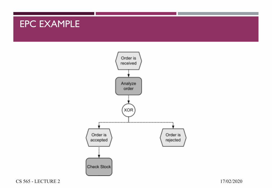
EPC EXAMPLE
17/02/2020CS 565 - LECTURE 2
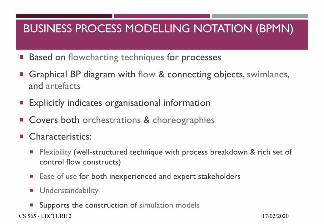
BUSINESS PROCESS MODELLING NOTATION (BPMN)
¡ Based on flowcharting techniques for processes
¡ Graphical BP diagram with flow & connecting objects, swimlanes, and artefacts
¡ Explicitly indicates organisational information
¡ Covers both orchestrations & choreographies
¡ Characteristics:¡ Flexibility (well-structured technique with process breakdown & rich set of
control flow constructs)
¡ Ease of use for both inexperienced and expert stakeholders
¡ Understandability
¡ Supports the construction of simulation models17/02/2020CS 565 - LECTURE 2
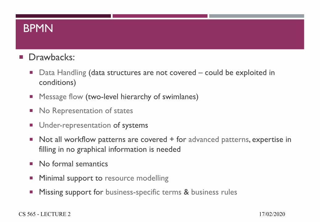
BPMN
¡ Drawbacks:¡ Data Handling (data structures are not covered – could be exploited in
conditions)
¡ Message flow (two-level hierarchy of swimlanes)
¡ No Representation of states
¡ Under-representation of systems
¡ Not all workflow patterns are covered + for advanced patterns, expertise in filling in no graphical information is needed
¡ No formal semantics
¡ Minimal support to resource modelling
¡ Missing support for business-specific terms & business rules
17/02/2020CS 565 - LECTURE 2
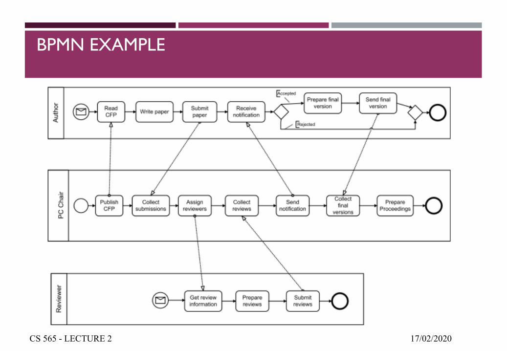
BPMN EXAMPLE
17/02/2020CS 565 - LECTURE 2
RECOMMENDED READING
¡ Ruth Sara Aguilar-Saven. Business Process Modelling: Review and Framework. Int. J. Production Economics 90 (2004) 129–149.
¡ M. Ould “Business Processes”, chapters 1, 2
¡ Koubarakis & Plexousakis, “A Formal Model for Business Process Modeling and Design”, Information Systems 27(2002), pp. 299-319.
¡ http://www.cds.caltech.edu/~murray/courses/afrl-sp12/L3_ltl-24Apr12.pdf
¡ https://www.youtube.com/watch?v=UfBFIAMOYgg&list=PLrAWWpbaj-7JlEV3_BfBLNYdYKrpqoC68&index=2
¡ https://www.youtube.com/watch?v=ztZsEI6C-mI
¡ https://www.youtube.com/watch?v=UfBFIAMOYgg
¡ https://creately.com/blog/diagrams/class-diagram-relationships/
17/02/2020CS 565 - LECTURE 2