C15153 Resistencia de Materiales - mecanica … · Capitulo 05_Hibbeler.indd 180 13/1/11 19:58:01...
19
C15153 Resistencia de Materiales Torsi´ on Roberto Ortega, PhD [email protected] cb Resistencia de Materiales | Torsi´on 1 of 18
Transcript of C15153 Resistencia de Materiales - mecanica … · Capitulo 05_Hibbeler.indd 180 13/1/11 19:58:01...

C15153Resistencia de Materiales
Torsion
Roberto Ortega, PhD
[email protected] cb Resistencia de Materiales | Torsion 1 of 18
TorsionHipotesis
Se analizaran los efectos que produce una carga de torsion sobre unelemento largo y recto como un eje o tubo de seccion transversal circular.
beams. Derivation of the equations used in the analysis of both torsion andbending follows these steps:
. Make simplifying assumptions about the deformation based on experi-mental evidence.. Determine the strains that are geometrically compatible with the as-sumed deformations.. Use Hooke’s law to express the equations of compatibility in terms ofstresses.. Derive the equations of equilibrium. (These equations provide the re-lationships between the stresses and the applied loads.)
3.2 Torsion of Circular Shafts
a. Simplifying assumptions
Figure 3.1 shows the deformation of a circular shaft that is subjected toa twisting couple (torque) T. To visualize the deformation, we scribe thestraight line AB on the surface of the shaft before the torque is applied. Afterloading, this line deforms into the helix AB 0 as the free end of the shaftrotates through the angle y. During the deformation, the cross sectionsare not distorted in any manner—they remain plane, and the radius r doesnot change. In addition, the length L of the shaft remains constant. Based onthese observations, we make the following assumptions:
. Circular cross sections remain plane (do not warp) and perpendicularto the axis of the shaft.. Cross sections do not deform (there is no strain in the plane of thecross section).. The distances between cross sections do not change (the axial normalstrain is zero).
The deformation that results from the above assumptions is relativelysimple: Each cross section rotates as a rigid entity about the axis of the shaft.Although this conclusion is based on the observed deformation of a cylin-drical shaft carrying a constant internal torque, we assume that the resultremains valid even if the diameter of the shaft or the internal torque variesalong the length of the shaft.
FIG. 3.1 Deformation of a circular shaft caused by the torque T. The initiallystraight line AB deforms into a helix.
76 CHAPTER 3 Torsion
Copyright 2010 Cengage Learning. All Rights Reserved. May not be copied, scanned, or duplicated, in whole or in part. Due to electronic rights, some third party content may be suppressed from the eBook and/or eChapter(s). Editorial review has deemed that any suppressed content does not materially affect the overall learning experience. Cengage Learning reserves the right to remove additional content at any time if subsequent rights restrictions require it.
Consideremos un elemento macizode seccion circular empotrado en unextremo A sometido a un momentotorsor T en el extremo libre B.
Tras aplicar la carga la linea rectaAB se deforma en una helice AB ′ yse produce un angulo de rotacion θen el extremo libre.
Las cargas de torsion actuan en planos perpendiculares al eje y losesfuerzos producidos no superan el lımite de proporcionalidad.
[email protected] cb Resistencia de Materiales | Torsion 2 of 18

TorsionHipotesis
Se analizaran los efectos que produce una carga de torsion sobre unelemento largo y recto como un eje o tubo de seccion transversal circular.
beams. Derivation of the equations used in the analysis of both torsion andbending follows these steps:
. Make simplifying assumptions about the deformation based on experi-mental evidence.. Determine the strains that are geometrically compatible with the as-sumed deformations.. Use Hooke’s law to express the equations of compatibility in terms ofstresses.. Derive the equations of equilibrium. (These equations provide the re-lationships between the stresses and the applied loads.)
3.2 Torsion of Circular Shafts
a. Simplifying assumptions
Figure 3.1 shows the deformation of a circular shaft that is subjected toa twisting couple (torque) T. To visualize the deformation, we scribe thestraight line AB on the surface of the shaft before the torque is applied. Afterloading, this line deforms into the helix AB 0 as the free end of the shaftrotates through the angle y. During the deformation, the cross sectionsare not distorted in any manner—they remain plane, and the radius r doesnot change. In addition, the length L of the shaft remains constant. Based onthese observations, we make the following assumptions:
. Circular cross sections remain plane (do not warp) and perpendicularto the axis of the shaft.. Cross sections do not deform (there is no strain in the plane of thecross section).. The distances between cross sections do not change (the axial normalstrain is zero).
The deformation that results from the above assumptions is relativelysimple: Each cross section rotates as a rigid entity about the axis of the shaft.Although this conclusion is based on the observed deformation of a cylin-drical shaft carrying a constant internal torque, we assume that the resultremains valid even if the diameter of the shaft or the internal torque variesalong the length of the shaft.
FIG. 3.1 Deformation of a circular shaft caused by the torque T. The initiallystraight line AB deforms into a helix.
76 CHAPTER 3 Torsion
Copyright 2010 Cengage Learning. All Rights Reserved. May not be copied, scanned, or duplicated, in whole or in part. Due to electronic rights, some third party content may be suppressed from the eBook and/or eChapter(s). Editorial review has deemed that any suppressed content does not materially affect the overall learning experience. Cengage Learning reserves the right to remove additional content at any time if subsequent rights restrictions require it.
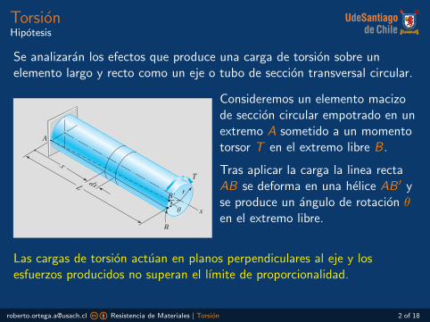
Durante la deformacion:
Las secciones circulares semantienen circulares.
Las secciones transversales a lolargo del eje permanecen planas.
Las lıneas radiales se conservanrectas durante la deformacion.
Si el angulo de giro es pequeno,la longitud del eje y su radio semantendran sin cambio.
Las cargas de torsion actuan en planos perpendiculares al eje y losesfuerzos producidos no superan el lımite de proporcionalidad.
[email protected] cb Resistencia de Materiales | Torsion 2 of 18
TorsionHipotesis
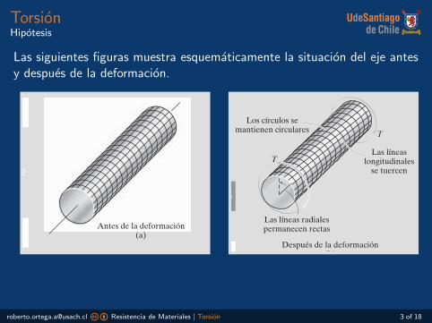
Las siguientes figuras muestra esquematicamente la situacion del eje antesy despues de la deformacion.180 CAPÍTULO 5 TORSIÓN
1
2
3
4
5
6
7
8
9
10
11
Si el eje está fijo en uno de sus extremos y se aplica un par de torsión a su otro extremo, el plano gris oscuro de la figura 5-2 se distorsionará en forma sesgada como se muestra en la misma figura. Aquí, una línea radial situada en la sección transversal a una distancia x del extremo fijo del eje girará un ángulo (x). El ángulo (x), definido de esta forma, se denomi-na ángulo de giro. Éste depende de la posición x y varía a lo largo del eje como se muestra en la figura.
Con el fin de entender la manera en que esta distorsión hace que el material se deforme, se aislará un pequeño elemento situado a una distan-cia radial (rho) de la línea central del eje, figura 5-3. Debido a una de- formación como la indicada en la figura 5-2, las caras frontal y posterior del elemento experimentarán una rotación, la cara posterior de (x) y la cara frontal de (x) + . Como resultado, la diferencia en estas rotacio-nes, , hace que el elemento esté sometido a deformación cortante. Para calcular esta deformación, observe que antes de ésta el ángulo entre las aristas AB y AC era de 90°; sin embargo, después de la deformación los bordes del elemento son AD y AC, y el ángulo entre ellos es de . A partir de la definición de deformación cortante, ecuación 2-4, se tiene
Observe la deformación del elemento rec-tangular cuando esta barra de caucho se somete a un par de torsión.
g = p2
- u¿
Antes de la deformación(a)
Después de la deformación(b)
Las líneaslongitudinales
se tuercen
Los círculos semantienen circulares
Las líneas radialespermanecen rectas
T
T
Figura 5-2
Figura 5-1
T
x
y
x
El ángulo de giro f(x) aumenta a medida que se incrementa x.
Planosin deformar
Planodeformado
z
f(x)
Capitulo 05_Hibbeler.indd 180 13/1/11 19:58:01
180 CAPÍTULO 5 TORSIÓN
1
2
3
4
5
6
7
8
9
10
11
Si el eje está fijo en uno de sus extremos y se aplica un par de torsión a su otro extremo, el plano gris oscuro de la figura 5-2 se distorsionará en forma sesgada como se muestra en la misma figura. Aquí, una línea radial situada en la sección transversal a una distancia x del extremo fijo del eje girará un ángulo (x). El ángulo (x), definido de esta forma, se denomi-na ángulo de giro. Éste depende de la posición x y varía a lo largo del eje como se muestra en la figura.
Con el fin de entender la manera en que esta distorsión hace que el material se deforme, se aislará un pequeño elemento situado a una distan-cia radial (rho) de la línea central del eje, figura 5-3. Debido a una de- formación como la indicada en la figura 5-2, las caras frontal y posterior del elemento experimentarán una rotación, la cara posterior de (x) y la cara frontal de (x) + . Como resultado, la diferencia en estas rotacio-nes, , hace que el elemento esté sometido a deformación cortante. Para calcular esta deformación, observe que antes de ésta el ángulo entre las aristas AB y AC era de 90°; sin embargo, después de la deformación los bordes del elemento son AD y AC, y el ángulo entre ellos es de . A partir de la definición de deformación cortante, ecuación 2-4, se tiene
Observe la deformación del elemento rec-tangular cuando esta barra de caucho se somete a un par de torsión.
g = p2
- u¿
Antes de la deformación(a)
Después de la deformación(b)
Las líneaslongitudinales
se tuercen
Los círculos semantienen circulares
Las líneas radialespermanecen rectas
T
T
Figura 5-2
Figura 5-1
T
x
y
x
El ángulo de giro f(x) aumenta a medida que se incrementa x.
Planosin deformar
Planodeformado
z
f(x)
Capitulo 05_Hibbeler.indd 180 13/1/11 19:58:01
[email protected] cb Resistencia de Materiales | Torsion 3 of 18

TorsionDeformacion
Para analizar la deformacion al interior del eje consideremos una longitudinfinitesimal dx del eje, como muestra la figura. Eliminemos tambienalgunas capas y dejemos el cilindro de radio ρ.
Puesto que las secciones estan separadas unadistancia infinitesimal, la diferencia entre susrotaciones dθ es tambien infinitesimal.
Debido a la rotacion dθ que sufre la linearecta CD, el punto D se desplaza hasta unanueva posicion D ′.
Observando la distorsion del elemento conlineas segmentadas es facil reconocer que elangulo γ es la deformacion por corte delelemento.
b. Compatibility
To analyze the deformation in the interior of the shaft in Fig. 3.1, we con-sider the portion of the shaft shown in Fig. 3.2(a). We first isolate a segmentof the shaft of infinitesimal length dx and then ‘‘peel’’ o¤ its outer layer,leaving us with the cylindrical core of radius r. As the shaft deforms, the twocross sections of the segment rotate about the x-axis. Because the cross sec-tions are separated by an infinitesimal distance, the di¤erence in their rota-tions, denoted by the angle dy, is also infinitesimal. We now imagine that thestraight line CD has been drawn on the cylindrical surface. As the crosssections undergo the relative rotation dy, CD deforms into the helix CD 0. Byobserving the distortion of the shaded element, we recognize that the helixangle g is the shear strain of the element.
From the geometry of Fig. 3.2(a), we obtain DD 0 ¼ r dy ¼ g dx, fromwhich the shear strain is
g ¼ dy
dxr (3.1)
The quantity dy=dx is the angle of twist per unit length, where y is expressedin radians. The corresponding shear stress, illustrated in Fig. 3.2(b), isdetermined from Hooke’s law:
t ¼ Gg ¼ Gdy
dxr (3.2)
Note that Gðdy=dxÞ in Eq. (3.2) is independent of the radial distance r.Therefore, the shear stress varies linearly with the radial distance r from theaxis of the shaft. The variation of the shear stress acting on the cross sectionis illustrated in Fig. 3.3. The maximum shear stress, denoted by tmax, occursat the surface of the shaft.
c. Equilibrium
For the shaft to be in equilibrium, the resultant of the shear stress acting ona cross section must be equal to the internal torque T acting on that crosssection. Figure 3.4 shows a cross section of the shaft containing a di¤erentialelement of area dA located at the radial distance r from the axis of the shaft.The shear force acting on this area is dP ¼ t dA ¼ Gðdy=dxÞr dA, directedperpendicular to the radius. Hence, the moment (torque) of dP about thecenter O is r dP ¼ Gðdy=dxÞr2 dA. Summing the contributions of all thedi¤erential elements across the cross-sectional area A and equating the resultto the internal torque yields
ÐA r dP ¼ T , or
Gdy
dx
ð
A
r2 dA ¼ T
Recognizing thatÐ
A r2 dA ¼ J is (by definition) the polar moment of inertiaof the cross-sectional area, we can write this equation as Gðdy=dxÞJ ¼ T , or
dy
dx¼ T
GJ(3.3)
FIG. 3.2 (a) Shear strain of amaterial element caused by twistingof the shaft; (b) the correspondingshear stress.
FIG. 3.3 Distribution of shearstress along the radius of a circularshaft.
FIG. 3.4 Calculating the resultantof the shear stress acting on the crosssection. Resultant is a couple equalto the internal torque T.
3.2 Torsion of Circular Shafts 77
Copyright 2010 Cengage Learning. All Rights Reserved. May not be copied, scanned, or duplicated, in whole or in part. Due to electronic rights, some third party content may be suppressed from the eBook and/or eChapter(s). Editorial review has deemed that any suppressed content does not materially affect the overall learning experience. Cengage Learning reserves the right to remove additional content at any time if subsequent rights restrictions require it.
DD ′ = ρ dθ = γ dx
γ = ρdθ
dx
[email protected] cb Resistencia de Materiales | Torsion 4 of 18

TorsionEsfuerzo
Aplicando la Ley de Hooke (relacion linealentre la tension y la deformacion) se obtieneel esfuerzo cortante:
τ = G γ = Gdθ
dxρ
Observese que el termino G dθdx no depende
de la distancia ρ, por tanto el esfuerzo decorte varıa linealmente con la distanciaradial ρ medida desde el eje longitudinal.
La variacion del esfuerzo cortante que actuaen la seccion transversal muestra que elesfuerzo maximo τmax se produce en lasuperficie externa del eje.
b. Compatibility
To analyze the deformation in the interior of the shaft in Fig. 3.1, we con-sider the portion of the shaft shown in Fig. 3.2(a). We first isolate a segmentof the shaft of infinitesimal length dx and then ‘‘peel’’ o¤ its outer layer,leaving us with the cylindrical core of radius r. As the shaft deforms, the twocross sections of the segment rotate about the x-axis. Because the cross sec-tions are separated by an infinitesimal distance, the di¤erence in their rota-tions, denoted by the angle dy, is also infinitesimal. We now imagine that thestraight line CD has been drawn on the cylindrical surface. As the crosssections undergo the relative rotation dy, CD deforms into the helix CD 0. Byobserving the distortion of the shaded element, we recognize that the helixangle g is the shear strain of the element.
From the geometry of Fig. 3.2(a), we obtain DD 0 ¼ r dy ¼ g dx, fromwhich the shear strain is
g ¼ dy
dxr (3.1)
The quantity dy=dx is the angle of twist per unit length, where y is expressedin radians. The corresponding shear stress, illustrated in Fig. 3.2(b), isdetermined from Hooke’s law:
t ¼ Gg ¼ Gdy
dxr (3.2)
Note that Gðdy=dxÞ in Eq. (3.2) is independent of the radial distance r.Therefore, the shear stress varies linearly with the radial distance r from theaxis of the shaft. The variation of the shear stress acting on the cross sectionis illustrated in Fig. 3.3. The maximum shear stress, denoted by tmax, occursat the surface of the shaft.
c. Equilibrium
For the shaft to be in equilibrium, the resultant of the shear stress acting ona cross section must be equal to the internal torque T acting on that crosssection. Figure 3.4 shows a cross section of the shaft containing a di¤erentialelement of area dA located at the radial distance r from the axis of the shaft.The shear force acting on this area is dP ¼ t dA ¼ Gðdy=dxÞr dA, directedperpendicular to the radius. Hence, the moment (torque) of dP about thecenter O is r dP ¼ Gðdy=dxÞr2 dA. Summing the contributions of all thedi¤erential elements across the cross-sectional area A and equating the resultto the internal torque yields
ÐA r dP ¼ T , or
Gdy
dx
ð
A
r2 dA ¼ T
Recognizing thatÐ
A r2 dA ¼ J is (by definition) the polar moment of inertiaof the cross-sectional area, we can write this equation as Gðdy=dxÞJ ¼ T , or
dy
dx¼ T
GJ(3.3)
FIG. 3.2 (a) Shear strain of amaterial element caused by twistingof the shaft; (b) the correspondingshear stress.
FIG. 3.3 Distribution of shearstress along the radius of a circularshaft.
FIG. 3.4 Calculating the resultantof the shear stress acting on the crosssection. Resultant is a couple equalto the internal torque T.
3.2 Torsion of Circular Shafts 77
Copyright 2010 Cengage Learning. All Rights Reserved. May not be copied, scanned, or duplicated, in whole or in part. Due to electronic rights, some third party content may be suppressed from the eBook and/or eChapter(s). Editorial review has deemed that any suppressed content does not materially affect the overall learning experience. Cengage Learning reserves the right to remove additional content at any time if subsequent rights restrictions require it.
[email protected] cb Resistencia de Materiales | Torsion 5 of 18
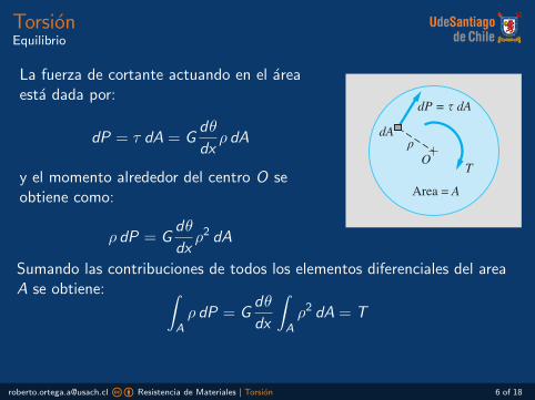
TorsionEquilibrio
La fuerza de cortante actuando en el areaesta dada por:
dP = τ dA = Gdθ
dxρ dA
y el momento alrededor del centro O seobtiene como:
ρ dP = Gdθ
dxρ2 dA
b. Compatibility
To analyze the deformation in the interior of the shaft in Fig. 3.1, we con-sider the portion of the shaft shown in Fig. 3.2(a). We first isolate a segmentof the shaft of infinitesimal length dx and then ‘‘peel’’ o¤ its outer layer,leaving us with the cylindrical core of radius r. As the shaft deforms, the twocross sections of the segment rotate about the x-axis. Because the cross sec-tions are separated by an infinitesimal distance, the di¤erence in their rota-tions, denoted by the angle dy, is also infinitesimal. We now imagine that thestraight line CD has been drawn on the cylindrical surface. As the crosssections undergo the relative rotation dy, CD deforms into the helix CD 0. Byobserving the distortion of the shaded element, we recognize that the helixangle g is the shear strain of the element.
From the geometry of Fig. 3.2(a), we obtain DD 0 ¼ r dy ¼ g dx, fromwhich the shear strain is
g ¼ dy
dxr (3.1)
The quantity dy=dx is the angle of twist per unit length, where y is expressedin radians. The corresponding shear stress, illustrated in Fig. 3.2(b), isdetermined from Hooke’s law:
t ¼ Gg ¼ Gdy
dxr (3.2)
Note that Gðdy=dxÞ in Eq. (3.2) is independent of the radial distance r.Therefore, the shear stress varies linearly with the radial distance r from theaxis of the shaft. The variation of the shear stress acting on the cross sectionis illustrated in Fig. 3.3. The maximum shear stress, denoted by tmax, occursat the surface of the shaft.
c. Equilibrium
For the shaft to be in equilibrium, the resultant of the shear stress acting ona cross section must be equal to the internal torque T acting on that crosssection. Figure 3.4 shows a cross section of the shaft containing a di¤erentialelement of area dA located at the radial distance r from the axis of the shaft.The shear force acting on this area is dP ¼ t dA ¼ Gðdy=dxÞr dA, directedperpendicular to the radius. Hence, the moment (torque) of dP about thecenter O is r dP ¼ Gðdy=dxÞr2 dA. Summing the contributions of all thedi¤erential elements across the cross-sectional area A and equating the resultto the internal torque yields
ÐA r dP ¼ T , or
Gdy
dx
ð
A
r2 dA ¼ T
Recognizing thatÐ
A r2 dA ¼ J is (by definition) the polar moment of inertiaof the cross-sectional area, we can write this equation as Gðdy=dxÞJ ¼ T , or
dy
dx¼ T
GJ(3.3)
FIG. 3.2 (a) Shear strain of amaterial element caused by twistingof the shaft; (b) the correspondingshear stress.
FIG. 3.3 Distribution of shearstress along the radius of a circularshaft.
FIG. 3.4 Calculating the resultantof the shear stress acting on the crosssection. Resultant is a couple equalto the internal torque T.
3.2 Torsion of Circular Shafts 77
Copyright 2010 Cengage Learning. All Rights Reserved. May not be copied, scanned, or duplicated, in whole or in part. Due to electronic rights, some third party content may be suppressed from the eBook and/or eChapter(s). Editorial review has deemed that any suppressed content does not materially affect the overall learning experience. Cengage Learning reserves the right to remove additional content at any time if subsequent rights restrictions require it.
Sumando las contribuciones de todos los elementos diferenciales del areaA se obtiene: ∫
Aρ dP = G
dθ
dx
∫Aρ2 dA = T
[email protected] cb Resistencia de Materiales | Torsion 6 of 18
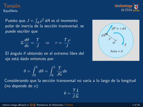
TorsionEquilibrio
Puesto que J =∫A ρ
2 dA es el momentopolar de inercia de la seccion transversal, sepuede escribir que
Gdθ
dx=
T
J⇒ τ =
T ρ
J
El angulo θ obtenido en el extremo libre deleje esta dado entonces por:
θ =
∫ L
0dθ =
∫ L
0
T
JGdx
b. Compatibility
To analyze the deformation in the interior of the shaft in Fig. 3.1, we con-sider the portion of the shaft shown in Fig. 3.2(a). We first isolate a segmentof the shaft of infinitesimal length dx and then ‘‘peel’’ o¤ its outer layer,leaving us with the cylindrical core of radius r. As the shaft deforms, the twocross sections of the segment rotate about the x-axis. Because the cross sec-tions are separated by an infinitesimal distance, the di¤erence in their rota-tions, denoted by the angle dy, is also infinitesimal. We now imagine that thestraight line CD has been drawn on the cylindrical surface. As the crosssections undergo the relative rotation dy, CD deforms into the helix CD 0. Byobserving the distortion of the shaded element, we recognize that the helixangle g is the shear strain of the element.
From the geometry of Fig. 3.2(a), we obtain DD 0 ¼ r dy ¼ g dx, fromwhich the shear strain is
g ¼ dy
dxr (3.1)
The quantity dy=dx is the angle of twist per unit length, where y is expressedin radians. The corresponding shear stress, illustrated in Fig. 3.2(b), isdetermined from Hooke’s law:
t ¼ Gg ¼ Gdy
dxr (3.2)
Note that Gðdy=dxÞ in Eq. (3.2) is independent of the radial distance r.Therefore, the shear stress varies linearly with the radial distance r from theaxis of the shaft. The variation of the shear stress acting on the cross sectionis illustrated in Fig. 3.3. The maximum shear stress, denoted by tmax, occursat the surface of the shaft.
c. Equilibrium
For the shaft to be in equilibrium, the resultant of the shear stress acting ona cross section must be equal to the internal torque T acting on that crosssection. Figure 3.4 shows a cross section of the shaft containing a di¤erentialelement of area dA located at the radial distance r from the axis of the shaft.The shear force acting on this area is dP ¼ t dA ¼ Gðdy=dxÞr dA, directedperpendicular to the radius. Hence, the moment (torque) of dP about thecenter O is r dP ¼ Gðdy=dxÞr2 dA. Summing the contributions of all thedi¤erential elements across the cross-sectional area A and equating the resultto the internal torque yields
ÐA r dP ¼ T , or
Gdy
dx
ð
A
r2 dA ¼ T
Recognizing thatÐ
A r2 dA ¼ J is (by definition) the polar moment of inertiaof the cross-sectional area, we can write this equation as Gðdy=dxÞJ ¼ T , or
dy
dx¼ T
GJ(3.3)
FIG. 3.2 (a) Shear strain of amaterial element caused by twistingof the shaft; (b) the correspondingshear stress.
FIG. 3.3 Distribution of shearstress along the radius of a circularshaft.
FIG. 3.4 Calculating the resultantof the shear stress acting on the crosssection. Resultant is a couple equalto the internal torque T.
3.2 Torsion of Circular Shafts 77
Copyright 2010 Cengage Learning. All Rights Reserved. May not be copied, scanned, or duplicated, in whole or in part. Due to electronic rights, some third party content may be suppressed from the eBook and/or eChapter(s). Editorial review has deemed that any suppressed content does not materially affect the overall learning experience. Cengage Learning reserves the right to remove additional content at any time if subsequent rights restrictions require it.
Considerando que la seccion transversal no varıa a lo largo de la longitud(no depende de x):
θ =T L
J G
[email protected] cb Resistencia de Materiales | Torsion 7 of 18

TorsionFormulas de torsion
El cortante maximo se obtiene reemplazando ρ por el radio del eje:
τmax =T r
J
Seccion maciza
r
D
J = πr4
2
J = πd4
32
τmax =2T
π r3
=16T
π d3
Seccion huecaD
d
D
J = π(R4−r4)2
J = π(D4−d4)32
τmax =2T R
π (R4 − r4)
=16T D
π (D4 − d4)
[email protected] cb Resistencia de Materiales | Torsion 8 of 18
TorsionPotencia transmitida
La potencia P transmitida por un par constante T que gira con velocidadangular constante ω esta dada por:
P = ωT
donde ω se mide en radianes por unida de tiempo.
Si el eje gira a una frecuencia f (revoluciones por unidad de tiempo) yω = 2πf , se tiene:
P = 2πf T
El momento torsor transmitido puede expresarse como:
T =P
2πf
[email protected] cb Resistencia de Materiales | Torsion 9 of 18

TorsionEjemplo
La figura muestra un eje circular macizo de 2 in de diametro que seencuentra empotrado en el extremo C y esta sujeto a las cargasTA = 900 lb·ft y TB = 400 lb·ft
1 Determine el esfuerzo maximo de corte en los segmentos AB y BCdel eje.
2 Calcule el angulo de rotacion en el extremo libre A. UseG = 12× 106 psi para el acero.
Sample Problem 3.1
Figure (a) shows a 2-in.-diameter solid steel cylinder that is built into the support atC and subjected to the torques TA and TB. (1) Determine the maximum shear stressesin segments AB and BC of the cylinder; and (2) compute the angle of rotation of endA. Use G ¼ 12" 106 psi for steel.
3 ftTB = 400 lb·ft TA = 900 lb·ft
5 ft
(a)
(b) FBDs (c) FBDs (using the right-hand rule)
C A
x
2 in. dia.
TB = 400 lb·ft
TB = 400 lb·ft
TC = 500 lb·ft
TBC = 500 lb·ft
TA = 900 lb·ft
TA = 900 lb·ft
3 ft 5 ft 3 ft 5 ftC A
B A
x
TB = 400 lb·ftTBC = 500 lb·ft TA = 900 lb·ft5 ft
B A
TA = 900 lb·ftTAB = 900 lb·ft
A A
TB = 400 lb·ftTC = 500 lb·ft TA = 900 lb·ft
BC A
TAB = 900 lb·ft TA = 900 lb·ft
x
x
x
x
x
B
B
Solution
Preliminary calculations
Before we can find the required stresses and the rotation of end A, we must first useequilibrium analysis to determine the torque in each of the two segments of the cylinder.
Figure (b) displays three FBDs. The top FBD shows the torques acting uponthe entire cylinder. The middle and bottom FBDs expose the internal torques actingon arbitrary sections of segments AB and BC, respectively. Applying the momentequilibrium equation, !Mx ¼ 0, determines the reactive torque at C to beTC ¼ 500 lb # ft, with the torques in the segments being TAB ¼ 900 lb # ft andTBC ¼ 500 lb # ft. Both internal torques are positive according to the sign conventionin Fig. 3.5. Furthermore, note that the torque in each segment is constant.
You may find it convenient to use the equivalent FBDs shown in Fig. (c),where the torques are represented as double-headed vectors using the right-hand rule.
81
Copyright 2010 Cengage Learning. All Rights Reserved. May not be copied, scanned, or duplicated, in whole or in part. Due to electronic rights, some third party content may be suppressed from the eBook and/or eChapter(s). Editorial review has deemed that any suppressed content does not materially affect the overall learning experience. Cengage Learning reserves the right to remove additional content at any time if subsequent rights restrictions require it.
[email protected] cb Resistencia de Materiales | Torsion 10 of 18
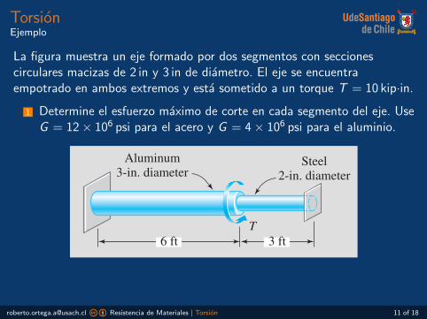
TorsionEjemplo
La figura muestra un eje formado por dos segmentos con seccionescirculares macizas de 2 in y 3 in de diametro. El eje se encuentraempotrado en ambos extremos y esta sometido a un torque T = 10 kip·in.
1 Determine el esfuerzo maximo de corte en cada segmento del eje. UseG = 12× 106 psi para el acero y G = 4× 10⁶ psi para el aluminio.
The polar moment of inertia for the cylinder is
J ¼ pd4
32¼ pð2Þ4
32¼ 1:5708 in:4
Part 1
We calculate the maximum shear stress in each segment using Eq. (3.5b) as follows(converting the torques to pound-inches):
ðtmaxÞAB ¼TABr
J¼ ð900$ 12Þð1:0Þ
1:5708¼ 6880 psi Answer
ðtmaxÞBC ¼TBCr
J¼ ð500$ 12Þð1:0Þ
1:5708¼ 3820 psi Answer
Part 2
The rotation of end A of the cylinder is obtained by summing the angles of twist ofthe two segments:
yA ¼ yA=B þ yB=C
Using Eq. (3.4b), we obtain (converting the lengths to inches and the torques topound-inches)
yA ¼TABLAB þ TBCLBC
GJ¼ 900$ 12ð Þ 5$ 12ð Þ þ 500$ 12ð Þ 3$ 12ð Þ
12$ 106ð Þ 1:5708ð Þ¼ 0:045 84rad ¼ 2:63 Answer
The positive result indicates that the rotation vector of A is in the positive x-direction;that is, yA is directed counterclockwise when viewed from A toward C.
1Sample Problem 3.2
The shaft in Fig. (a) consists of a 3-in.-diameter aluminum segment that is rigidly joinedto a 2-in.-diameter steel segment. The ends of the shaft are attached to rigid supports.Calculate the maximum shear stress developed in each segment when the torque T ¼ 10kip & in. is applied. Use G ¼ 4$ 106 psi for aluminum and G ¼ 12$ 106 psi for steel.
Solution
Equilibrium From the FBD of the entire shaft in Fig. (b), the equilibrium equation is
82
Copyright 2010 Cengage Learning. All Rights Reserved. May not be copied, scanned, or duplicated, in whole or in part. Due to electronic rights, some third party content may be suppressed from the eBook and/or eChapter(s). Editorial review has deemed that any suppressed content does not materially affect the overall learning experience. Cengage Learning reserves the right to remove additional content at any time if subsequent rights restrictions require it.
[email protected] cb Resistencia de Materiales | Torsion 11 of 18

TorsionTubos de pared delgada
Consideremos un tubo de pared delgada (Rt > 10) sometido a un torqueT , como muestra la figura. La seccion es constante al lo largo del tubopero el espesor t podrıa variar a largo de la seccion.
Consider the thin-walled tube subjected to the torque T shown in Fig.3.7(a). We assume the tube to be prismatic (constant cross section), but thewall thickness t is allowed to vary within the cross section. The surface thatlies midway between the inner and outer boundaries of the tube is called themiddle surface. If t is small compared to the overall dimensions of the crosssection, the shear stress t induced by torsion can be shown to be almostconstant through the wall thickness of the tube and directed tangent to themiddle surface, as illustrated in Fig. 3.7(b). It is convenient to introducethe concept of shear flow q, defined as the shear force per unit edge length ofthe middle surface. Thus, the shear flow is
q ¼ tt (3.7)
If the shear stress is not constant through the wall thickness, then t inEq. (3.7) should be viewed as the average shear stress.
We now show that the shear flow is constant throughout the tube. Thisresult can be obtained by considering equilibrium of the element shown inFig. 3.7(c). In labeling the shear flows, we assume that q varies in the lon-gitudinal (x) as well as the circumferential (s) directions. Thus, the termsðqq=qxÞ dx and ðqq=qsÞ ds represent the changes in the shear flow over thedistances dx and ds, respectively. The force acting on each side of the ele-ment is equal to the shear flow multiplied by the edge length, resulting in theequilibrium equations
SFx ¼ 0 qþ qq
qsds
! "dx% q dx ¼ 0
SFs ¼ 0 qþ qq
qxdx
! "ds% q ds ¼ 0
which yield qq=qx ¼ qq=qs ¼ 0, thereby proving that the shear flow is con-stant throughout the tube.
To relate the shear flow to the applied torque T, consider the crosssection of the tube in Fig. 3.8. The shear force acting over the infinitesimal
FIG. 3.7 (a) Thin-walled tube in torsion; (b) shear stress in the wall of the tube;(c) shear flows on wall element.
92 CHAPTER 3 Torsion
Copyright 2010 Cengage Learning. All Rights Reserved. May not be copied, scanned, or duplicated, in whole or in part. Due to electronic rights, some third party content may be suppressed from the eBook and/or eChapter(s). Editorial review has deemed that any suppressed content does not materially affect the overall learning experience. Cengage Learning reserves the right to remove additional content at any time if subsequent rights restrictions require it.
Si el espesor t es pequenocomparado con las dimensiones de laseccion, el esfuerzo cortante τinducido por la torsion puedeconsiderarse constante a traves delespesor de la pared del tubo ytangente a la superficie media.
La superficie que se encuentra entre la superficie exterior e interior deltubo se denomina superficie media.
[email protected] cb Resistencia de Materiales | Torsion 12 of 18

TorsionTubos de pared delgada
Podemos definir el flujo de cortante, como la fuerza de cortante porunidad de longitud como:
q = τ t
Consider the thin-walled tube subjected to the torque T shown in Fig.3.7(a). We assume the tube to be prismatic (constant cross section), but thewall thickness t is allowed to vary within the cross section. The surface thatlies midway between the inner and outer boundaries of the tube is called themiddle surface. If t is small compared to the overall dimensions of the crosssection, the shear stress t induced by torsion can be shown to be almostconstant through the wall thickness of the tube and directed tangent to themiddle surface, as illustrated in Fig. 3.7(b). It is convenient to introducethe concept of shear flow q, defined as the shear force per unit edge length ofthe middle surface. Thus, the shear flow is
q ¼ tt (3.7)
If the shear stress is not constant through the wall thickness, then t inEq. (3.7) should be viewed as the average shear stress.
We now show that the shear flow is constant throughout the tube. Thisresult can be obtained by considering equilibrium of the element shown inFig. 3.7(c). In labeling the shear flows, we assume that q varies in the lon-gitudinal (x) as well as the circumferential (s) directions. Thus, the termsðqq=qxÞ dx and ðqq=qsÞ ds represent the changes in the shear flow over thedistances dx and ds, respectively. The force acting on each side of the ele-ment is equal to the shear flow multiplied by the edge length, resulting in theequilibrium equations
SFx ¼ 0 qþ qq
qsds
! "dx% q dx ¼ 0
SFs ¼ 0 qþ qq
qxdx
! "ds% q ds ¼ 0
which yield qq=qx ¼ qq=qs ¼ 0, thereby proving that the shear flow is con-stant throughout the tube.
To relate the shear flow to the applied torque T, consider the crosssection of the tube in Fig. 3.8. The shear force acting over the infinitesimal
FIG. 3.7 (a) Thin-walled tube in torsion; (b) shear stress in the wall of the tube;(c) shear flows on wall element.
92 CHAPTER 3 Torsion
Copyright 2010 Cengage Learning. All Rights Reserved. May not be copied, scanned, or duplicated, in whole or in part. Due to electronic rights, some third party content may be suppressed from the eBook and/or eChapter(s). Editorial review has deemed that any suppressed content does not materially affect the overall learning experience. Cengage Learning reserves the right to remove additional content at any time if subsequent rights restrictions require it.
Los terminos ∂q/∂x dx y∂q/∂s ds representan loscambios sobre lasdistancias dx y ds.
Se puede demostrar que el flujo es constante atraves del tubo. Supongamos que q varıa enfuncion de la direccion longitudinal x y ladireccion circunferencial s. La fuerza actuandoen cada cara estarıa dada por:
(q +∂q
∂sds)dx − q dx = 0, (1)
(q +∂q
∂xdx)ds − q ds = 0, (2)
lo que conduce a ∂q/∂s = ∂q/∂x = 0.
[email protected] cb Resistencia de Materiales | Torsion 13 of 18

TorsionTubos de pared delgada
La fuerza de cortante actuando en una longitud infinitesimal ds de lasuperficie media es dP = q ds. El momento que produce esta fuerzaalrededor del punto O es r dP = q ds r .
edge length ds of the middle surface is dP ¼ q ds. The moment of this forceabout an arbitrary point O in the cross section is r dP ¼ ðq dsÞr, where r isthe perpendicular distance of O from the line of action of dP. Equilibriumrequires that the sum of these moments must be equal to the applied torqueT; that is,
T ¼þ
S
qr ds (a)
where the integral is taken over the closed curve formed by the intersectionof the middle surface and the cross section, called the median line.
The integral in Eq. (a) need not be evaluated formally. Recalling that qis constant, we can take it outside the integral sign, so that Eq. (a) can bewritten as T ¼ q
ÞS r ds. But from Fig. 3.8 we see that r ds ¼ 2 dA0, where
dA0 is the area of the shaded triangle. Therefore,Þ
S r ds ¼ 2A0, where A0 isthe area of the cross section that is enclosed by the median line. Con-sequently, Eq. (a) becomes
T ¼ 2A0q (3.8a)
from which the shear flow is
q ¼ T
2A0(3.8b)
We can find the angle of twist of the tube by equating the work doneby the shear stress in the tube to the work of the applied torque T. Let usstart by determining the work done by the shear flow acting on the elementin Fig. 3.7(c). The deformation of the element is shown in Fig. 3.9, where gis the shear strain of the element. We see that work is done on the elementby the shear force dP ¼ q ds as it moves through the distance g dx. If we as-sume that g is proportional to t (Hooke’s law), this work is
dU ¼ 1
2ðforce$ distanceÞ ¼ 1
2ðq dsÞðg dxÞ
Substituting g ¼ t=G ¼ q=ðGtÞ yields
dU ¼ q2
2Gtds dx (b)
The work U of the shear flow for the entire tube is obtained byintegrating Eq. (b) over the middle surface of the tube. Noting that q and Gare constants and t is independent of x, we obtain
U ¼ q2
2G
ðL
0
þ
S
ds
t
$ %dx ¼ q2L
2G
þ
S
ds
t(c)
Conservation of energy requires U to be equal to the work of the appliedtorque; that is, U ¼ Ty=2. After substituting the expression for q fromEq. (3.8b) into Eq. (c), we obtain
T
2A0
$ %2 L
2G
þ
S
ds
t¼ 1
2Ty
FIG. 3.8 Calculating the resultantof the shear flow acting on the crosssection of the tube. Resultant is acouple equal to the internal torque T.
FIG. 3.9 Deformation of elementcaused by shear flow.
3.3 Torsion of Thin-Walled Tubes 93
Copyright 2010 Cengage Learning. All Rights Reserved. May not be copied, scanned, or duplicated, in whole or in part. Due to electronic rights, some third party content may be suppressed from the eBook and/or eChapter(s). Editorial review has deemed that any suppressed content does not materially affect the overall learning experience. Cengage Learning reserves the right to remove additional content at any time if subsequent rights restrictions require it.
De la figura podemos deducirque r ds = 2 dA0, por tanto∫S r ds = 2A0.
Por equilibrio, la suma de todos losmomentos debe ser igual al torqueaplicado
T =
∫Sq r ds = q
∫Sr ds
Puesto que∫S r ds = 2A0, donde A0 es
el area encerrada por la linea media, seobtiene:
T = 2A0q ⇒ τ =T
2A0t
[email protected] cb Resistencia de Materiales | Torsion 14 of 18

TorsionEjemplo
Considere un tubo de seccion transversal como se muestra en la figura ycon espesor constante de t = 3
8 in.
1 Si el tubo esta sometido a un torque T = 67,5 klb·in, calcule elesfuerzo de corte maximo en la seccion. Desprecie la concentracion deesfuerzos en las esquinas.Sample Problem 3.6
A steel tube with the cross section shown carries a torque T. The tube is 6 ft long andhas a constant wall thickness of 3/8 in. (1) Compute the torsional sti¤ness k ¼ T=y ofthe tube. (2) If the tube is twisted through 0:5", determine the shear stress in the wallof the tube. Use G ¼ 12# 106 psi, and neglect stress concentrations at the corners.
Solution
Part 1
Because the wall thickness is constant, the angle of twist is given by Eq. (3.9b):
y ¼ TLS
4GA20 t
Therefore, the torsional sti¤ness of the tube can be computed from
k ¼ T
y¼ 4GA2
0 t
LS
The area enclosed by the median line is
A0 ¼ average width# height ¼ 6þ 4
2
! "ð5Þ ¼ 25 in:2
and the length of the median line is
S ¼ 6þ 4þ 2ffiffiffiffiffiffiffiffiffiffiffiffiffiffiffiffi12 þ 52
p¼ 20:20 in:
Consequently, the torsional sti¤ness becomes
k ¼ 4ð12# 106Þð25Þ2ð3=8Þð6# 12Þð20:20Þ ¼ 7:735# 106 lb ' in:=rad
¼ 135:0# 103 lb ' in:=deg Answer
Part 2
The torque required to produce an angle of twist of 0:5" is
T ¼ ky ¼ ð135:0# 103Þð0:5Þ ¼ 67:5# 103 lb ' in:
which results in the shear flow
q ¼ T
2A0¼ 67:5# 103
2ð25Þ¼ 1350 lb=in:
The corresponding shear stress is
t ¼ q
t¼ 1350
3=8¼ 3600 psi Answer
1
95
Copyright 2010 Cengage Learning. All Rights Reserved. May not be copied, scanned, or duplicated, in whole or in part. Due to electronic rights, some third party content may be suppressed from the eBook and/or eChapter(s). Editorial review has deemed that any suppressed content does not materially affect the overall learning experience. Cengage Learning reserves the right to remove additional content at any time if subsequent rights restrictions require it.
[email protected] cb Resistencia de Materiales | Torsion 15 of 18

TorsionEjemplo
Considere un tubo hueco sometido a un torque T .
1 Determine cuando las siguientes expresiones para calcular el esfuerzocortante en la seccion son equivalentes o similares. En otras palabra,cuando se puede considerar como tubo de pared delgada.
Seccion huecaD
d
D
J = π(R4−r4)2
J = π(D4−d4)32
τ =T ρ
J
Tubo de pared delgada
D
d
D
t = D−d2
τ =T
2A0t
[email protected] cb Resistencia de Materiales | Torsion 16 of 18

TorsionBibliografıa
A. Pytel y J. Kiusalaas, Mechanics of Materials. Second Edition, 2010.
A. Pytel y F.L.Singer, Resistencia de Materiales. Cuarta Edicion, 2009.
R. C. Hibbeler, Mecanica de Materiales. Octava Edicion, 2011.
[email protected] cb Resistencia de Materiales | Torsion 17 of 18

C15153Resistencia de Materiales
Torsion
Roberto Ortega, PhD
[email protected] cb Resistencia de Materiales | Torsion 18 of 18