Cat - Electro Persa · Cuautitlan Izcalli Estado de México. C.P ... Debido a la naturaleza...
128
DUCTO CHAROLAS ABRAZADERAS CANALETA TUBERÍA UNICANAL 2013 Fabricantes de soportes y ductos para instalaciones electricas
Transcript of Cat - Electro Persa · Cuautitlan Izcalli Estado de México. C.P ... Debido a la naturaleza...
DU
CT
O
CH
AR
OL
AS
AB
RA
ZA
DE
RA
S
CA
NA
LE
TA
TU
BE
RÍA
UN
ICA
NA
L
S U C U R S A L E S
Cat
álog
o G
ener
al
201
3G
ener
al C
atal
og
2013Fabricantes de soportes y ductos
para instalaciones electricas
MÉXICO (CUAUTITLAN IZCALLI)Calle Alessandro Volta Lote. 1 y 2.
Parque Industrial CuamatlaCuautitlan Izcalli Estado de México.
C.P. 54730TEL: 01 (55) 58-70-11-97
Lada Sin Costo 01800-CROSS LINE 27677 5463
MÉXICO (CENTRO)Revillagigedo 36-A Col. Centro
C.P. 06050 México, DF.TEL: 01 (55) 55-21-68-31
55-21-68-51 53-86-46-54
FAX: 01 (55) 55-21-71-20
ESTADO DE MÉXICO.Calle Manzanillo No. 807
Col. San Jerónimo ChicahualcoMetepec Edo. Méx. C.P, 52170
TEL: 01 (722) 275-08-43 180-19-57
Juncos No.104 Col. Villa de las FloresCoacalco, Edo. Méx. C.P. 55710
TEL: 01 (55) 58-75-77-19FAX: 01 (55) 59-05-21-47
QUERÉTARO, QUERÉTAROAv. Del Bambú No. 13
Col. El Carrizal Santiago de QuerétaroC.P. 76030
TEL: 01 (442) 242-40-37 242-10-01
MONTERREY, NUEVO LEÓNPriv. Ernesto García Ortiz No. 60
Col. Del Norte, C.P. 64500TEL: 01 (81) 83-51-87-31
Lada Sin Costo 01 800-713-93-75 713-09-06
CIUDAD MADERO, TAMAULIPASTEL: 01 (833) 210-57-96
GUADALAJARA, JALCalle 2 No. 2345
Zona Industrial C.P. 44940TEL: 01 (33) 38-10-25-00
38-10-25-05
TIJUANA, B.C.Calle Abasolo No. 7970Col. Mérida C.P. 22660
Tijuana Baja California N.TEL: 01 (664) 689-81-54
629-14-77
SAN LUIS POTOSÍAv. Tecnológico No. 108-A
Col. 21 de Marzo S.L.P. C.P. 78437
TEL: 01 (444) 822-51-08
Av. Salvador Nava Martínez No.704-BCol. Nuevo Paseo S.L.P C.P.78328
TEL: 01 (444) 841-59-71
LEÓN GUANAJUATOBlvd. Juan José Torres Landa No. 6101
Col. San Isidro C.P. 37510León, Gto.
TEL: 01 (477) 771-88-40
HERMOSILLO, SONORACalle Simón Bley No. 8 entreC/Nayarit y C/Aguascalientes
Col. Olivares C.P. 83180TEL: 01 (662) 260-70-90
260-70-94
Calle Manuel I. Loaiza No.162Col. Olivares, Hillo. C.P. 83180
TEL: 01 (662) 216-16-36
Calle Félix Soria No.33ACol. San Benito, Hillo. C.P. 83190
TEL: 01 (662) 267-04-45
PUEBLA, PUEBLAVictoria No.31 Col. Sanctorum C.P.72100
TEL: 01 (222) 187-72-67 210-58-78
MÉRIDA, YUCATÁNAv. Yucatán No. 801 Col. Jardines
de Mérida Yucatán C.P. 97135TEL: 01 (999) 155-80-40
CULIACÁN, SINALOAAv. Ejército Nacional No.2897
Col. Emiliano Zapata C.P. 80260TEL: 01 (667) 727-04-29
718-30-66

1
MENSAJE DEL DIRECTOR
CROSS LINE se complace en presentar la nueva versión del Catálogo de productos integrando más y mejor información referente a los Sistemas de So-portería para Instalaciones Eléctricas.
Una de las metas de este catálogo es proporcionar a nuestros clientes herramientas que les permitan resolver de manera práctica y eficaz los problemas que se les presenten en el campo de la Soportería para Cables, esperando que éste cumpla amplia-mente sus expectativas.
Nuestros productos estan respaldados bajo las Nor-mas NEMA, CSA, UL y ANCE, ya que están fabri-cados con los más estrictos estándares de calidad, así como su fabricación con materiales de primera calidad, permitiéndonos ofrecerle seguridad y con-fianza en sus proyectos, garantizando su completa satisfacción. CROSS LINE agradece a todos nues-tros clientes y amigos de la Industria Eléctrica y de Construcción por la confianza que han depositado en nosotros.
SUCCESS NEEDS A STRONG AND RELIABLE FOUNDATION
My staff and I are particularly pleased to submit this new CROSS LINE catalogue. With its new arrange-ment, new layout and more detailed overview and information than ever before. It presents the exten-sive range of CROSS LINE cable support systems.
It’s our goal to submit to you a convincing planning and arrangement tool enabling you to solve practi-cally every conceivable problem in the field of cable support technology, economically and safely, in-cluding construction and material quality, as well as the processing and delivery security by a close co-operation with all the branches we got. At the same time it means the safety of the NEMA, CSA, UL and ANCE standards applied to CROSS LINE systems.
We take this opportunity to thank all our partners from the fields of planning, trade, industry and the whole same business for decades of cooperation, providing the future with a trustful partnership. We guarantee that this principle will be the basis of our joint future success as it has been in the past.
CATÁLOGO CROSS LINE

2
PRODUCTOS
Sección 1 “Unicanal” 7Sección 1.1 Tramos rectos unicanal 12Sección 1.2 Accesorios de ensamble “unicanal” 15Sección 1.3 Accesorios de montaje “unicanal” 21
Sección 2 “Ducto” 27Sección 2.1 Ducto cuadrado embisagrado 30Sección 2.2 Ducto con tapa a presión NEMA 1 / IP-41 34Sección 2.3 Ducto industrial NEMA 12 / IP-43 38Sección 2.4 Ducto bridado y embisagrado NEMA 3, 3R, 4 4X / IP-67 42Sección 2.5 Ducto con vena y cañuela NEMA 5, 12 / IP-55 46
Sección 3 “Abrazaderas para tubería” 50Sección 3.1 Abrazadera tipo columpio 50Sección 3.2 Abrazadera para tubería 51Sección 3.3 Abrazadera tipo “U” 52
Información técnica de charolas Sección 4 “Charolas” 53Sección 4.1 Tramos rectos y accesorios, “charola” tipo escalera 58Sección 4.2 Tramos rectos y accesorios, “charola” tipo fondo sólido 69Sección 4.3 Accesorios de ensamble 78Sección 4.4 Accesorios de montaje 83
Sección 4.5 “Charolas de fibra de vidrio” 88Sección 4.6 “Charolas tipo marino” 102Sección 4.7 “Charolas tipo malla” 107
Sección 5 “Canal ventilado” 114Sección 5.1 Tramos rectos y accesorios de ensamble 115Sección 5.2 Accesorios de montaje “canal” 118
Sección 6 “Tubería” 119Índice por clave de catálogo 121

3
PRODUCTS
Section 1 “Unistrut” 7Section 1.1 Straigth sections “Unistrut” 12Section 1.2 Unistrut fittings 15Section 1.3 Unistrut accesories 21
Section 2 “Wireway” 27Section 2.1 Square wireway NEMA 1 / IP-30 30Section 2.2 Pressed cover wireway NEMA 1 / IP-40 34Section 2.3 Industrial type wireway NEMA 12 / IP-42 38Section 2.4 Flanged and hinged wireway NEMA 3, 3R, 4, 4X / IP-66 42Section 2.5 Packed and pressed wireway NEMA 5, 12 / IP-54 46
Section 3 “Pipe clamps” 50Section 3.1 Suspension rod pipe clamp 50Section 3.2 Conduit pipe clamp 51Section 3.3 U-bolt 52
Technical informationSection 4 “Cable trays” 53Section 4.1 Straigth sections fittings for ladder type 58Section 4.2 Straigth sections fittings for solid trough type 69Section 4.3 Splice plates 78Section 4.4 Supports and brackets 83
Section 4.5 “Fiber glass cable tray ladder type” 88Section 4.6 “Marine type cable tray system” 102Section 4.7 “Cable tray system wire mesh type” 107
Section 5 “Cable channel” 114Section 5.1 Straigth sections and fittings 115Section 5.2 Cable channel supports 118
Section 6 “Rigid conduit pipe” 119Index for catalog key 121
4
INTRODUCCIÓN
CROSS LINE, con más de 30 años de servicio a México, es una de las empresas más importantes en la fabricación de Soportería para instalaciones eléctricas.
Se ha preocupado porque sus sistemas de soportes para instalaciones eléctricas, tipo Charola Metálica y Unicanal se encuentren respaldados por tecnolo-gía de vanguardia con un compromiso inalterable de calidad.
CROSS LINE, con sus plantas de manufactura y distribuidoras localizadas en México, D.F., Monte-rrey, Hermosillo, Tijuana, Querétaro, Tamaulipas, Guadalajara, Guanajuato y San Luis Potosí, cuen-tan con los últimos adelantos tecnológicos en la fa-bricación de soportes para instalaciones eléctricas realizando con empeño y dedicación nuevo desa-rrollo de productos para cubrir las necesidades de la Industria Nacional e Internacional.
CROSS LINE, manufactura soportes con los más altos estándares de calidad y tiene reconocimientos de organismos como ANCE, CFE., LYF., PEMEX, DGCOSTC, S.T.C. METRO, ASA, FFCC. Entre otros y cumplen sobradamente con las normas y especifi-caciones NOM, NMX, U.L., IEEE, NEMA, etc.
CROSS LINE, a implementado orgullosamente el sistema de calidad ISO 9002 para garantizar un ser-vicio distintivo de la más ALTA CALIDAD, esforzán-donos día a día para que usted obtenga los mejores resultados de seguridad y confiabilidad en sus ins-talaciones eléctricas.
Con el fin de mejorar y mantener nuestra calidad, todos nuestros productos están sujetos a cambio de diseño sin previo aviso tomando como base las nor-mas anteriormente descritas.
INTRODUCTION
CROSS LINE, is a leading manufacturer of steel and aluminum products which are used in the support of cables, pipe and equipment for industrial comercial, utility and OEM installations.
CROSS LINE, is proud of the exacting standards of design engineering and manufacturing in each product. Our costumer, have access to the most complete support systems offered in the industry including cable tray, metal framming, pipe hanger and slotted strut.
CROSS LINE products are produced and distrib-uted in our plants which are located in México, D.F., Monterrey, Hermosillo, Tijuana, Querétaro, Tamauli-pas, Guadalajara, Guanajuato and San Luis Potosí. This catalog is designed as a helpful tool for cable tray and support products for construction and maintenance engineers.
If a unique application requires a special product not included in this catalog, CROSS LINE’s technical personnel are ready to furnish design consultation and realistic cost estimation.
With the purpose of improving and maintain our quality, all our products are subject to change with-out notice, based in norms previously described.

5
INFORMACIÓN TÉCNICA DE MATERIALES Y ACABADOS DE LOS PRODUCTOS CROSS LINE
MATERIALES DE FABRICACIÓN
Los sistemas de soportería para cables CROSS LINE son fabricados con materiales de la más alta calidad, adquiridos a empresas certificadas bajo ISO 9000, además son rigurosamente verificados en nuestras instalaciones para entregar a usted un producto acorde con las necesidades de calidad y excelencia que demanda el desarrollo industrial.
Los materiales disponibles para la fabricación de CHAROLAS, UNICANAL, DUCTO, CANALETA, ABRAZADERAS Y SOPORTERÍA para cables son:
• Acero al carbón AISI C 1010 HR/CR• Acero inoxidable AISI-304• Aluminio AA 6063.• Poliéster reforzado con fibra de vidrio, au-
toextinguible y protegido contra rayos ultra-violeta.
RECUBRIMIENTOS PROTECTORES
Debido a la naturaleza energética de los metales, en ambientes donde se presentan condiciones galvánicas (humedad, agua salda, etc.) o exposi-ción a químicos corrosivos, la aplicación de recu-brimientos anticorrosivos aumentará la vida útil de los materiales. El sistema de soportería para cables de CROSS LINE puede ser suministrado con los si-guientes recubrimientos protectores:
1. Para productos de Acero al Carbón:
√ Galvanizado mecánico ASTM B 695√ Galvanizado por inmersión en caliente después
de manufactura según ASTM A 123√ Galvanizado por inmersión en caliente antes de
manufactura según ASTM A 525√ Galvanizado electrolítico según ASTM B 633√ Tropicalizado√ Recubrimiento de PVC según NEMA RN 1√ Acabado epóxico.
Nota: el acero al carbón no se surte en acabado natural.
2. Para productos de aluminio
√ Acabado natural (oxidación protectora natural)√ Recubrimiento de PVC según NEMA RN 1√ Acabado epóxico Los productos de acero inoxidable se surten en acabado natural.
Para recubrimientos especiales favor de consultar con nuestro Departamento de Ingeniería.
6
TECHNICAL INFORMATION OF MATERIALS AND FINISHED PRODUCT CROSS LINE
MANUFACTURING MATERIALS
CROSS LINE cable tray system is made with high quality materials, all our suppliers are ISO 9000 certificated, also the materials are strictly inspected in our facilities to provide you a product according with your needs of quality and excellence.
The available materials for CABLE TRAY SYSTEM, SQUARE WIREWAY, PIPE CLAMPS, and SUPPORTS are:
• Carbon steel AISI C 1010 HR/CR• Stainless steel AISI-304• Aluminum AA 6063.• Polyester fiber glass reinforced flame-
retardant, auto-extinguish and protectedagainst UV.
FINISHES
Environment where a galvanic condition (humidity, salted water, etc.) or corrosive chemical exposure is present needs the application of a corrosion proof finish to plus the product’s lifetime. CROSS LINE cable tray systems are available in the next protective finishes
1. For carbon steel products:
√ Mechanical Galvanized ASTM B 695√ Hot dip galvanized after manufacture under
ASTM A 123√ Hot dip galvanized before manufacture under
ASTM A 525√ Electrogalvanized under ASTM B 633√ Chromium-zinc coat √ PVC coat under NEMA RN 1√ Epoxy coat
Carbon steel products are not available in natural finish.
2. For aluminum products
√ Natural finish (a coat of natural Al O)√ PVC coat under NEMA RN 1√ Epoxy coat
Stainless steel products are available in natural fin-ish.
For special coatings please consult our Technical Department.
7
SISTEMA DE BASTIDORES UNICANAL
¿Requiere en su industria un sistema de soportes rápido de instalar, económico y versátil?
El sistema de soportes UNICANAL fabricado por CROSS LINE es la solución. Este sistema cuenta con gran versatilidad reduciendo su inversión ya que el diseño permite que la instalación se modi-fique a conveniencia sin necesidad de gastos adi-cionales.
Con el sistema UNICANAL, las estructuras que to-marían horas en soldarse se arman fácilmente en minutos. Su tuerca de seguridad hace esto posible aun en sitios de difícil acceso ya que no requiere de herramientas especiales. Además el sistema UNI-CANAL es fácilmente desarmable para transpor-tarlo y ensamblarlo donde se requiera. El sistema es ideal como soporte de tuberías, instalación de sistemas de iluminación, soporte de charolas para cables, mesas de trabajo, etc. El sistema de so-portes UNICANAL hace que las demás soluciones parezcan problemas. Consúltenos, nuestro depar-tamento técnico esta a sus ordenes.
CARACTERÍSTICAS Y ESPECIFICACIONES DEL SISTEMA DE BASTIDORES METÁLICOS
“UNICANAL”
Los componentes del sistema de soporte UNICA-NAL son: el unicanal, la tuerca de seguridad y sus diferentes conectores.
El unicanal es fabricado en acero al carbón, acero inoxidable, fibra de vidrio o aluminio.
Un lado del canal cuenta con una ranura a lo lar-go con bordes doblados. Estas ranuras sirven para sujetar la tuerca de seguridad y al mismo tiempo sirven de guías para las ranuras de la tuerca UNI-CANAL.
Las tuercas UNICANAL son fabricadas en acero al carbón; sus extremos redondeados permiten insta-larse en cualquier punto a lo largo del UNICANAL y girarse hasta hacer coincidir sus ranuras estriadas con la guía del UNICANAL; el resorte con el que cuenta la tuerca impedirá movimientos de la tuerca quedando lista para el ensamble de los conectores.
Tanto las tuercas como los tornillos cuentan con roscas tipo UNC estándar.
Los conectores son fabricados en acero al carbón, acero inoxidable o aluminio. (Ver acabados).
CROSS LINE se reserva el derecho de cambiar los diseños y dimensiones sin previo aviso.
UNISTRUT METAL FRAME SYSTEM
Does your company require an economical, flexible and easy to install support system?
The UNISTRUT support system manufactured for CROSS LINE is the solution. This kind of system is conformed by the channel, lock nut and other joint accessories, which will give you the versatility and cost reduction wanted when system modifications are needed.
By using UNISTRUT frame system, structures that usually take hours to be welded can be easily as-sembled in a few minutes. Its adjustable lock nut makes possible, exact and simple installations, even in the most difficult access places. This instal-lation doesn’t require special tools.
When you need to transport it, you can do it fast and easily. The system can be used as a pipe support, in the illumination system installation, in cable tray sys-tems, work benches, etc. UNISTRUT support system makes other solutions look like problems. Contact us, our technical department is ready for you.
“UNISTRUT” METAL FRAME SYSTEM CHARACTERISTICS AND SPECIFICATIONS
UNISTRUT metal frame system includes: The chan-nel, the lock nut and the fittings.
The channel can be made of carbon steel, stainless steel, fiberglass reinforced or aluminum.
One side of the channel has a row of slots which run all along of it, each slot can be used to fasten the security lock and at the same time as a guide for the UNISTRUT lock nuts.
UNISTRUT’s lock nuts are made of carbon steel. Its rounded edges allow their installation at any point along the channel and can be turned to align the grooves with the channel guides. The spring located in the lower side of the nut prevent movements, ready to the fitting assembly. Each nut and its bolt have an unified thread.
Fittings are made of carbon steel, stainless steel or aluminum; unless otherwise specified.
CROSS LINE reserve the right to change the de-signs, dimensions or specifications without notice.
Sección 1 Unicanal Section 1 Unistrut
UN
ICA
NA
L Pr
oduc
tos
Cro
ss L
ine
8
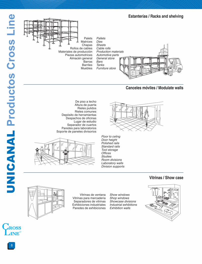
PaletsMatricesChapas
Rollos de cablesMateriales de producción
Piezas automotricesAlmacén general
BarrasBarriles
Muebles
PalletsDiesSheetsCable rollsProduction materialsAutomotive partsGeneral storeBarsTanksFurniture store
De piso a techoAltura de puerta
Rieles pulidosRieles comunes
Depósito de herramientasDespachos de oficinas
Lugar de estudioSeparador de cuartos
Paredes para laboratoriosSoporte de paneles divisorios
Floor to celingDoor heightPolished railsStandard railsTool storageOfficesStudiesRoom divisionsLaboratory wallsDivision supports
Vitrinas de ventanaVitrinas para mercaderíaSeparadores de vitrinas
Exhibiciones industrialesParedes de exhibiciones
Show windowsShop windowsShowcase divisionsIndustrial exhibitionsExhibition walls
Estanterías / Racks and shelving
Canceles móviles / Modulate walls
Vitrinas / Show case

9
UN
IST
RU
T C
ross
Lin
e P
rodu
cts
Equipo fluorescenteReflectores
VitrinasAlumbrado de estudios
Cielorasos luminosos
Fluorescent lightingFloodlightsShow windows lightStage lightingCeling lighting
InstrumentosBastidores de transporte
EstanteríaBastidor de horno
Soporte de rayos xCasetas para soldadores
Armado de escenariosMuelles de embarcaciones
EntrepisosEscaleras
Escaleras para incendiosToldos
InstrumentsTransportation racksStandard racksOven racksX ray supportWelding householdsStage racksDocksEntresolsStairsFire stairsAwnings, vanity tent
ConductosBarra de conducciónSoportes para cables
Equipo eléctricosSoportes para tubería conduit
RacewayElectrical barCable tray supportElectrical equipmentConduit support
Cañerías para aguaPuntales para túneles
Conducción de instalaciones sanitariasTuberías de vapor
TuberíasSujeción de tubería a ductos
Piping raksTunnel pipe stanchionsSanitary pipes supportVapor pipesStandard pipesPipe to wireway clamps
Insertos de concretoInsertos para paredSoporte para vigas
TrapeciosParedes de cortinas
Concrete insertsCantilever insertsBeam attachmentsTrapeze hangersWall framing
Aplicaciones especiales / Special aplications
Soportes para alumbrado / Lighting support
Soportes eléctricos / Electrical supports
Soportes mecánicos / Mechanical applications
Soportes estructurales / Structural supports
UN
ICA
NA
L Pr
oduc
tos
Cro
ss L
ine
10
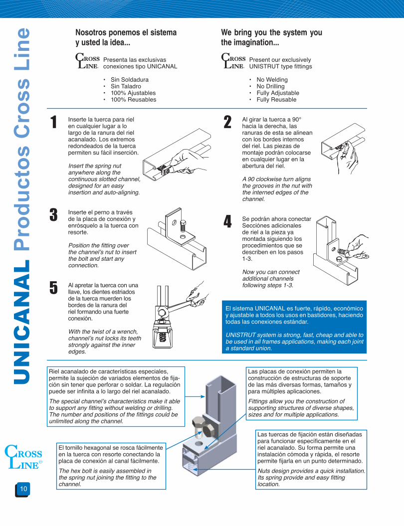
Inserte la tuerca para riel en cualquier lugar a lo largo de la ranura del riel acanalado. Los extremos redondeados de la tuerca permiten su fácil inserción.
Insert the spring nut anywhere along the continuous slotted channel, designed for an easy insertion and auto-aligning.
Presenta las exclusivas conexiones tipo UNICANAL
• Sin Soldadura• Sin Taladro• 100% Ajustables• 100% Reusables
Present our exclusively UNISTRUT type fittings
• No Welding• No Drilling• Fully Adjustable• Fully Reusable
Nosotros ponemos el sistema y usted la idea...
We bring you the system you the imagination...
1 Al girar la tuerca a 90° hacia la derecha, las ranuras de esta se alinean con los bordes internos del riel. Las piezas de montaje podrán colocarse en cualquier lugar en la abertura del riel.
A 90 clockwise turn aligns the grooves in the nut with the interned edges of the channel.
2
Inserte el perno a través de la placa de conexión y enrósquelo a la tuerca con resorte.
Position the fitting over the channel’s nut to insert the bolt and start any connection.
3 Se podrán ahora conectar Secciónes adicionales de riel a la pieza ya montada siguiendo los procedimientos que se describen en los pasos 1-3.
Now you can connect additional channels following steps 1-3.
4
Al apretar la tuerca con una llave, los dientes estriados de la tuerca muerden los bordes de la ranura del riel formando una fuerte conexión.
With the twist of a wrench, channel’s nut locks its teeth strongly against the inner edges.
5El sistema UNICANAL es fuerte, rápido, económico y ajustable a todos los usos en bastidores, haciendo todas las conexiones estándar.
UNISTRUT system is strong, fast, cheap and able to be used in all frames applications, making each joint a standard union.
El tornillo hexagonal se rosca fácilmente en la tuerca con resorte conectando la placa de conexión al canal fácilmente.The hex bolt is easily assembled in the spring nut joining the fitting to the channel.
Las placas de conexión permiten la construcción de estructuras de soporte de las más diversas formas, tamaños y para múltiples aplicaciones.Fittings allow you the construction of supporting structures of diverse shapes, sizes and for multiple applications.
Las tuercas de fijación están diseñadas para funcionar específicamente en el riel acanalado. Su forma permite una instalación cómoda y rápida, el resorte permite fijarla en un punto determinado.Nuts design provides a quick installation. Its spring provide and easy fitting location.
Riel acanalado de características especiales, permite la sujeción de variados elementos de fija-ción sin tener que perforar o soldar. La regulación puede ser infinita a lo largo del riel acanalado.The special channel’s characteristics make it able to support any fitting without welding or drilling. The number and positions of the fittings could be unlimited along the channel.

11
UN
IST
RU
T C
ross
Lin
e P
rodu
cts
Uni
cana
l
Serie
100
0Se
rie 2
000
Serie
330
0Se
rie 4
000
Serie
500
0Se
rie 5
500
LU-6
000
PSLU
- __
__
LU-7
000
PRLU
- __
__
Med
idas
LU-1
000
41.3
x41.
3mm
LU-2
000
41.3
x41.
3mm
LU-3
300
41.3
x20.
6mm
LU-4
000
41.3
x41.
3mm
LU-5
000
41.3
x82.
6mm
LU-5
500
41.3
x61.
9mm
LU-6
000
20.6
x20.
6mm
Dep
ende
del
un
ican
al a
per
fora
rLU
-100
141
.3x8
2.6m
mLU
-200
141
.3x8
2.6m
mLU
-330
141
.3x4
1.3m
mLU
-400
141
.3x4
1.3m
mLU
-500
141
.3x1
65.2
mm
LU-5
501
41.3
x123
.8m
mLU
-700
020
.6x1
1mm
Aca
bado
sA
lum
inio
, Ace
ro a
l car
bón
galv
aniz
ado
por i
nmer
sión
en
calie
nte,
Ace
ro a
l car
bón
galv
aniz
ado
elec
trolít
ico,
Ace
ro in
oxid
able
,A
cero
pin
tado
(pin
tura
ele
ctro
stát
ica
híbr
ida)
, Ace
ro re
cubi
erto
de
PV
C, A
lum
inio
recu
bier
to d
e P
VC
, Lám
ina
galv
aniz
ada,
Fib
ra d
e vi
drio
(ver
pág
. 100
)
Serv
icio
lige
roSe
rvic
io p
esad
o
Her
raje
sun
ican
al
Con
exió
n pl
ana
Con
exió
n “U
”C
onex
ión
“Z”
Con
exió
n a
90º
Con
exió
n de
Ala
Bas
esTu
erca
uni
cana
lA
braz
ader
as y
m
orda
zas
Med
idas
Diá
met
ro o
rifici
o: 1
4.3m
m (0
.562
”), d
ista
ncia
ent
re c
entro
s: 4
7.6m
m (1
.875
”)P
ara
torn
illo
1/4”
, 5/
16”,
3/8”
y 1
/2”
Tubo
3/8
” a 6
”
Par
a cu
alqu
ier
serie
uni
cana
l.In
cluy
e to
rnill
ería
Aca
bado
sA
cero
al c
arbó
n ga
lvan
izad
o po
r inm
ersi
ón e
n ca
lient
e,A
cero
al c
arbó
n ga
lvan
izad
o el
ectro
lític
o, a
cero
inox
idab
le
Ace
ro a
l car
bón
galv
aniz
ado
elec
trolít
ico
Alu
min
io, a
cero
re
cubi
erto
de
PV
CA
cero
gal
vani
zado
, ac
ero
inox
idab
le,
lám
ina
galv
aniz
ada
UN
ICA
NA
L Pr
oduc
tos
Cro
ss L
ine
12
No. de catálogoCatalog number
Profundidad A mm (pulg)Depth A mm (pulg)
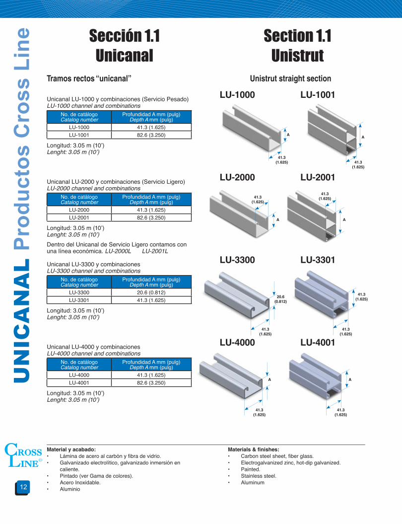
LU-1000 41.3 (1.625)LU-1001 82.6 (3.250)
LU-1000
Material y acabado:• Lámina de acero al carbón y fibra de vidrio.• Galvanizado electrolítico, galvanizado inmersión en caliente.• Pintado (ver Gama de colores).• Acero Inoxidable.• Aluminio
Materials&finishes:• Carbon steel sheet, fiber glass.• Electrogalvanized zinc, hot-dip galvanized.• Painted.• Stainless steel.• Aluminum
Unistrut straight section
Sección 1.1Unicanal
Section 1.1Unistrut
Longitud: 3.05 m (10’)Lenght: 3.05 m (10’)
LU-1001Tramos rectos “unicanal”
Unicanal LU-1000 y combinaciones (Servicio Pesado)LU-1000 channel and combinations
No. de catálogoCatalog number
Profundidad A mm (pulg)Depth A mm (pulg)
LU-2000 41.3 (1.625)LU-2001 82.6 (3.250)
LU-2000
Longitud: 3.05 m (10’)Lenght: 3.05 m (10’)
LU-2001Unicanal LU-2000 y combinaciones (Servicio Ligero)LU-2000 channel and combinations
No. de catálogoCatalog number
Profundidad A mm (pulg)Depth A mm (pulg)
LU-3300 20.6 (0.812)LU-3301 41.3 (1.625)
LU-3300 LU-3301Unicanal LU-3300 y combinacionesLU-3300 channel and combinations
Dentro del Unicanal de Servicio Ligero contamos con una línea económica. LU-2000L LU-2001L
No. de catálogoCatalog number
Profundidad A mm (pulg)Depth A mm (pulg)
LU-4000 41.3 (1.625)LU-4001 82.6 (3.250)
LU-4000 LU-4001Unicanal LU-4000 y combinacionesLU-4000 channel and combinations
A
A
20.6 (0.812)
A
41.3 (1.625)
41.3 (1.625)
41.3 (1.625)
41.3 (1.625)
41.3 (1.625)
41.3 (1.625)41.3
(1.625)
41.3 (1.625) 41.3
(1.625)
A
A
A
Longitud: 3.05 m (10’)Lenght: 3.05 m (10’)
Longitud: 3.05 m (10’)Lenght: 3.05 m (10’)
13
UN
IST
RU
T C
ross
Lin
e P
rodu
cts
No. de catálogoCatalog number
Peso kgWeight kg
LU-1000 6.2LU-1001 12.5LU-2000 5.1LU-2001 10.3LU-3300 4.3LU-3301 8.7LU-4000 3.6LU-4001 7.3LU-5500 8.1LU-5501 16.3
Unistrut weight
Canal con insertos sumar 1.4 kg Para PRLU- restar 0.2 kg Para PSLU-restar 0.4 kgLU-3184 P = 0.42 kg pieza
Pesos de unicanal
Peso aproximado por canal de 3.048 m de longitud.Aproximate weight for 10’ channel length.
For concret insert plus 3 lbFor PRLU- reduce 0.44 lbFor PSLU- reduce 0.88 lb0.92 lb unit
No. de catálogoCatalog number
Profundidad A mm (pulg)Depth A mm (pulg)
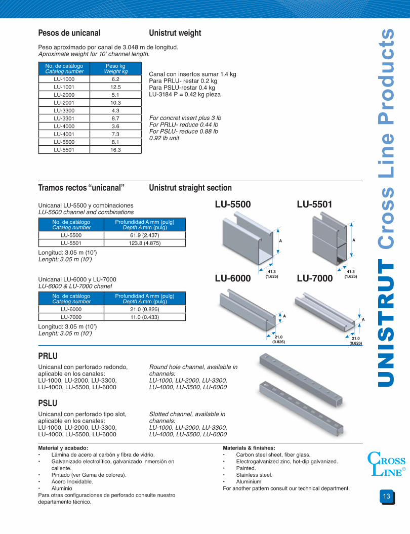
LU-5500 61.9 (2.437)LU-5501 123.8 (4.875)
LU-5500Unistrut straight section
Longitud: 3.05 m (10’)Lenght: 3.05 m (10’)
LU-5501Tramos rectos “unicanal”
Unicanal LU-5500 y combinacionesLU-5500 channel and combinations
No. de catálogoCatalog number
Profundidad A mm (pulg)Depth A mm (pulg)
LU-6000 21.0 (0.826)LU-7000 11.0 (0.433)
LU-6000
Longitud: 3.05 m (10’)Lenght: 3.05 m (10’)
LU-7000Unicanal LU-6000 y LU-7000LU-6000 & LU-7000 chanel
PRLUUnicanal con perforado redondo, aplicable en los canales:LU-1000, LU-2000, LU-3300, LU-4000, LU-5500, LU-6000
Round hole channel, available in channels:LU-1000, LU-2000, LU-3300, LU-4000, LU-5500, LU-6000
PSLUUnicanal con perforado tipo slot, aplicable en los canales:LU-1000, LU-2000, LU-3300, LU-4000, LU-5500, LU-6000
Slotted channel, available in channels:LU-1000, LU-2000, LU-3300, LU-4000, LU-5500, LU-6000
A
AA
A
Material y acabado:• Lámina de acero al carbón y fibra de vidrio.• Galvanizado electrolítico, galvanizado inmersión en caliente.• Pintado (ver Gama de colores).• Acero Inoxidable.• AluminioPara otras configuraciones de perforado consulte nuestro departamento técnico.
Materials&finishes:• Carbon steel sheet, fiber glass.• Electrogalvanized zinc, hot-dip galvanized.• Painted.• Stainless steel.• AluminiumFor another pattern consult our technical department.
41.3 (1.625)
21.0 (0.826)
21.0 (0.826)
41.3 (1.625)

UN
ICA
NA
L Pr
oduc
tos
Cro
ss L
ine
14
Unistrut straight sectionTramos rectos unicanal
Unicanal LU-1000 longitud de 2.00m con insertos
LU-3265
Material y acabado:• Material: lámina de acero al carbón.• Galvanizado electrolítico, galvanizado inmersión en caliente.
Materials&finishes:• Carbon steel sheet.• Electrogalvanized zinc, hot-dip galvanized.
Tira de plástico para cerrar el canalPlastic closure strip
Unicanal con insertosConcrete insert channel
Muro de concreto armadoConcrete ceiling, wall or floor
Plastic closure stripTira de plástico para terminación
LU-3184 PTira de plástico para cerrar el canal para usarse con unicanalLU-1000, LU-2000, LU-3300, LU-4000, LU-5500, LU-6000 y sus combinacio-nes.
Plastic closer strip for use in unistrut LU-1000, LU-2000, LU-3300 LU-4000, LU-5500, LU-6000 and their combina-tions.
Estas tiras son ideales para evitar la entrada de concreto cuando se instalan productos LU-3265
This strip is excelent to avoid the enter of concret when a LU-3265 is used
200
400
400
Materiales y acabados:
P: Cloruro de poliviniloGI: Lámina Galvanizada
Materials&finishes:
P: Polyvinyl ChlorideGI: Galvanized sheet
15
UN
IST
RU
T C
ross
Lin
e P
rodu
cts
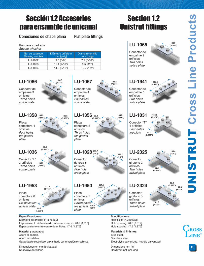
No. de catálogoCatalog number
Diámetro orificio Amm (pulg)
Diámetro tornillomm (pulg)
LU-1062 9.5 (3/8”) 7.9 (5/16”)LU-1063 11.1 (7/16”) 9.5 (3/8”)LU-1064 14.3 (9/16”) 12.7 (1/2”)
Flat plate fittings
Sección 1.2 Accesorios para ensamble de unicanal
Section 1.2Unistrut fittings
Conexiones de chapa plana
Rondana cuadradaSquare whasher
Especificaciones:Diámetro de orificio: 14.3 [0.562]Espaciamiento del centro de orificio al extremo: 20.6 [0.812]Espaciamiento entre centro de orificios: 47.6 [1.875]
Material y acabado:Acero al carbón.Acero inoxidable.Galvanizado electrolítico, galvanizado por inmersión en caliente.
Dimensiones en mm [pulgadas]No incluye tornillería.
Specifications:Hole size: 14.3 [0.562]Hole spacing: 20.6 [0.812]Hole spacing: 47.6 [1.875]
Materials&finishes:Strip steel.Stainless steel.Electrolytic galvanized, hot-dip galvanized.
Dimensions mm [in]Hardware not included.
LU-1358Placa conectora 4 orificiosFour holes tee gusset plate
LU-1356Placa conectora 3 orificiosThree holes tee gusset plate
LU-1031Conector “T” 4 orificiosFour holes tee plate
LU-1036Conector “L” 3 orificiosThree holes corner plate
LU-1028Conector de cruz 5 orificiosFive hole cross plate
LU-1953Placa conectora 6 orificiosSix holes tee gusset plate
LU-1950Placa conectora 7 orificiosSeven holes tee gusset plate
LU-2324Conector giratorio 3 orificiosThree holes swivel plate
LU-1067Conector de empalme 4 orificiosFour holes splice plate
LU-1065Conector de empalme 2 orificiosTwo holes splice plate
LU-1066Conector de empalme 3 orificiosThree holes splice plate
LU-1941Conector de empalme 5 orificiosFive holes splice plate
88.9(3.500”)
136.5(5.375”)
136.5(5.375”)
136.5(5.375”)
184.2(7.25”)
213.8(9.125”)
88.9(3.500”)
88.9(3.500”)
88.9(3.500”)
88.9(3.500”)
88.9(3.500”)
88.9(3.500”)
88.9(3.500”)
231.5 (9.113”)
231.5 (9.113”)
139.7(5.5”)
139.7(5.5”)
139.7(5.5”)
92.1(3.625”)
181.0 (7.125”)
47.6 (1.875”)
92.1(3.625”)
133.4(5.25”)LU-2325
Conector giratorio 2 orificiosTwo holes swivel plate

UN
ICA
NA
L Pr
oduc
tos
Cro
ss L
ine
16
Especificaciones:Diámetro de orificio: 14.3 [0.562]Espaciamiento del centro de orificio al extremo: 20.6 [0.812]Espaciamiento entre centro de orificios: 47.6 [1.875]
Material y acabado:Acero al carbón.Acero inoxidable.Galvanizado electrolítico, galvanizado por inmersión en caliente.
Dimensiones en mm [pulgadas]No incluye tornillería.
Specifications:Hole size: 14.3 [0.562]Hole spacing: 20.6 [0.812]Hole spacing: 47.6 [1.875]
Materials&finishes:Strip steel.Stainless steel.Electrolytic galvanized, hot-dip galvanized.
Dimensions mm [in]Hardware not included.
“U” fittingsConexiones en forma de “U”
LU-1376Conector de horquilla 2 orificiosTwo holes splice clevis
LU-1376AConector de horquilla 3 orificiosThree holes splice clevis
LU-1377Conector de horquilla 4 orificiosFour holes splice clevis
LU-1046AConector de copa 3 orificiosThree holes cup support plate
LU-3347Conector “U” 3 orificiosThree hole “U” support
LU-1043AConector “U” 6 orificiosSix hole “U” support
LU-1737Conector “U” 3 orificiosThree hole “U” support
LU-1047Conector “U” 5 orificiosFive hole “U” support
LU-1320Conector “U” con sujetador 2 orificiosStud ring connection
LU-1044Conector “U” 4 orificiosFour hole clevis
39.5(1.555”)
88.9(3.5”)
39.5(1.555”)
136.5 (5.375”)
39.5(1.555”)
184.1 (7.25”)
41.3 (1.625”)
41.3 (1.625”)
41.3 (1.625”)
41.3 (1.625”)
41.3 (1.625”)177.8
(7.0”)
42.1 (1.656”)
42.1 (1.656”) 42.1
(1.656”)
54.0 (2.125”)
83.3 (3.281”)
83.3 (3.281”)
20.6 (0.812”)
136.5 (5.375”)
136.5 (5.375”)
136.5 (5.375”)
82.5 (3.250”)

17
UN
IST
RU
T C
ross
Lin
e P
rodu
cts“Z” fittingsConexiones en forma de “Z”
LU-3345Conector “Z” 2 orificiosTwo hole “Z” support
LU-1736Conector 3 orificiosThree hole shelf corner connection
90° Angular fittingsConexiones angulares a 90º
LU-1326Conector angular 90º3 orificiosThree hole corner angle
LU-1325Conector angular 90º4 orificiosFour hole corner angle
LU-1026Conector angular 90º2 orificiosTwo hole corner angle
LU-1068Conector angular 90º2 orificiosTwo hole corner angle
LU-2235Conector angular 90º tipo trapecio 5 orificiosFive hole gussetted three way shelf angle
LU-1728Conector angular 90º tipo trapecio 5 orificiosFive hole gussetted shelf angle
LU-1346Conector angular 90º3 orificiosThree hole corner angle
LU-1458Conector angular 90º3 orificiosThree hole corner angle
LU-1045Conector “Z” 3 orificiosThree hole “Z” support
LU-1453Conector “Z” 4 orificiosFour hole “Z” support
95.3 (3.750”)
95.3 (3.750”)
41.3 (1.625”)
41.3 (1.625”)
41.3 (1.625”)
47.6 (1.875”)
79.4 (3.125”)
57.1 (2.250”)98.4
(3.875”)
41.3 (1.625”)
57.2 (2.250”)
104.8 (4.125”)
104.8 (4.125”)
104.8 (4.125”)
104.8 (4.125”)
79.4 (3.125”)
50.8 (2.0”)
47.6 (1.875”)
88.9(3.5”)
88.9(3.5”)
88.9(3.5”)
88.9(3.5”)88.9
(3.5”)
82.5 (3.250”)
20.6 (0.812”)
136.5 (5.375”)
Especificaciones:Diámetro de orificio: 14.3 [0.562]Espaciamiento del centro de orificio al extremo: 20.6 [0.812]Espaciamiento entre centro de orificios: 47.6 [1.875]
Material y acabado:Acero al carbón.Acero inoxidable.Galvanizado electrolítico, galvanizado por inmersión en caliente.
Dimensiones en mm [pulgadas]No incluye tornillería.
Specifications:Hole size: 14.3 [0.562]Hole spacing: 20.6 [0.812]Hole spacing: 47.6 [1.875]
Materials&finishes:Strip steel.Stainless steel.Electrolytic galvanized, hot-dip galvanized.
Dimensions mm [in]Hardware not included.

UN
ICA
NA
L Pr
oduc
tos
Cro
ss L
ine
18
LU-1037Conector angular 90º izquierdo 3 orificiosThree hole (left hand) offset bent angle
LU-1038Conector angular 90º derecho 3 orificiosThree hole (right hand) offset bent angle
LU-1033Conector “T” angular 90º derecho 4 orificiosFour hole (right hand) offset bent tee
LU-1357Conector angular 90º tipo trapecio 3 orificiosThree hole gusseted shelf angle
LU-1727Conector angular a 90º tipo trapecio 4 orificiosFour hole gusseted corner
LU-1956Conector de esquina reforzado derecho 6 orificiosSix hole (right hand) gussetted corner connection
LU-1957Conector de esquina reforzado izquierdo 6 orificiosSix hole (left hand) gussetted corner connetion
LU-1035Conector “T” angular 90º derecho 4 orificiosFour hole (right hand) offset bent tee angle
LU-1034Conector “T” angular 90º izquierdo 4 orificiosFour hole (left hand) offset bent tee angle
LU-1359Conector angular de 90º tipo trapecio 4 orificiosFour hole gussetted shelf angle
LU-1579Conector angular de 90º tipo trapecio 4 orificiosFour hole gussetted three way shelf angle
41.3 (1.625”)
41.3 (1.625”)
41.3 (1.625”)
41.3 (1.625”)
41.3 (1.625”)
41.3 (1.625”)
41.3 (1.625”)
57.2 (2.250”)
57.2 (2.250”)
47.6 (1.875”)
136.5 (5.375”)
136.5 (5.375”)
139.7 (5.500”)
104.8 (4.125”)
104.8 (4.125”) 104.8
(4.125”)
104.8 (4.125”)
88.9(3.5”)
88.9(3.5”)
88.9(3.5”)
88.9(3.5”)
88.9(3.5”) 88.9
(3.5”)
88.9(3.5”)
88.9(3.5”)
88.9(3.5”)
88.9(3.5”)
88.9(3.5”)
88.9(3.5”)
Especificaciones:Diámetro de orificio: 14.3 [0.562]Espaciamiento del centro de orificio al extremo: 20.6 [0.812]Espaciamiento entre centro de orificios: 47.6 [1.875]
Material y acabado:Acero al carbón.Acero inoxidable.Galvanizado electrolítico, galvanizado por inmersión en caliente.
Dimensiones en mm [pulgadas]No incluye tornillería.
Specifications:Hole size: 14.3 [0.562]Hole spacing: 20.6 [0.812]Hole spacing: 47.6 [1.875]
Materials&finishes:Strip steel.Stainless steel.Electrolytic galvanized, hot-dip galvanized.
Dimensions mm [in]Hardware not included.
19
UN
IST
RU
T C
ross
Lin
e P
rodu
cts
Especificaciones:Diámetro de orificio: 14.3 [0.562]Espaciamiento del centro de orificio al extremo: 20.6 [0.812]Espaciamiento entre centro de orificios: 47.6 [1.875]
Material y acabado:Acero al carbón.Acero inoxidable.Galvanizado electrolítico, galvanizado por inmersión en caliente.
Dimensiones en mm [pulgadas]No incluye tornillería.
Specifications:Hole size: 14.3 [0.562]Hole spacing: 20.6 [0.812]Hole spacing: 47.6 [1.875]
Materials&finishes:Strip steel.Stainless steel.Electrolytic galvanized, hot-dip galvanized.
Dimensions mm [in]Hardware not included.
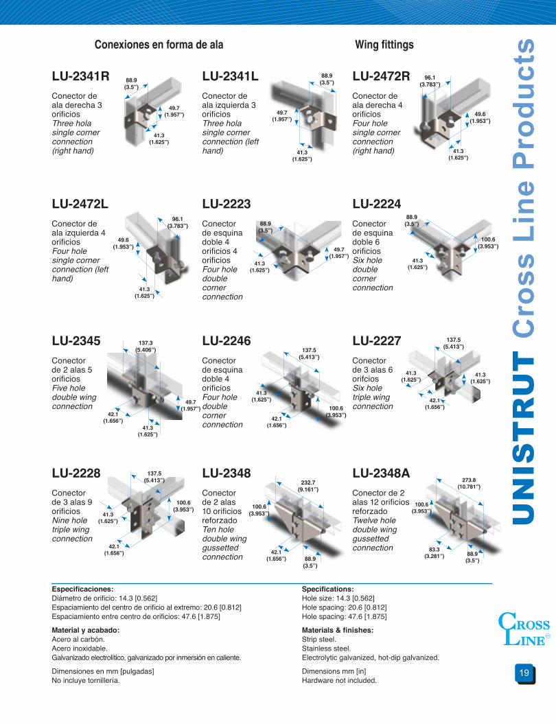
Wing fittingsConexiones en forma de ala
LU-2341RConector de ala derecha 3 orificiosThree hola single corner connection (right hand)
LU-2341LConector de ala izquierda 3 orificiosThree hola single corner connection (left hand)
LU-2472RConector de ala derecha 4 orificiosFour hole single corner connection (right hand)
LU-2472LConector de ala izquierda 4 orificiosFour hole single corner connection (left hand)
LU-2223Conector de esquina doble 4 orificios 4 orificiosFour hole double corner connection
LU-2224Conector de esquina doble 6 orificiosSix hole double corner connection
LU-2345Conector de 2 alas 5 orificiosFive hole double wing connection
LU-2246Conector de esquina doble 4 orificiosFour hole double corner connection
LU-2227Conector de 3 alas 6 orifciosSix hole triple wing connection
LU-2228Conector de 3 alas 9 orificiosNine hole triple wing connection
LU-2348Conector de 2 alas 10 orificios reforzadoTen hole double wing gussetted connection
LU-2348AConector de 2 alas 12 orificios reforzadoTwelve hole double wing gussetted connection
88.9(3.5”)
88.9(3.5”)
88.9(3.5”)
88.9(3.5”)
88.9(3.5”)
100.6 (3.953”)
100.6 (3.953”)
100.6 (3.953”) 100.6
(3.953”)
232.7 (9.161”)
88.9(3.5”)
83.3 (3.281”)
100.6 (3.953”)
273.8 (10.781”)
137.5 (5.413”) 137.5
(5.413”)
137.5 (5.413”)
137.3 (5.406”)
96.1 (3.783”)
96.1 (3.783”)
49.6 (1.953”)
49.6 (1.953”)
41.3 (1.625”)
41.3 (1.625”)
41.3 (1.625”)
41.3 (1.625”)
41.3 (1.625”)
41.3 (1.625”)
41.3 (1.625”)
41.3 (1.625”)
41.3 (1.625”)
42.1 (1.656”)
42.1 (1.656”)
42.1 (1.656”)
42.1 (1.656”)
42.1 (1.656”)
41.3 (1.625”)
41.3 (1.625”)
49.7 (1.957”) 49.7
(1.957”)
49.7 (1.957”)
49.7 (1.957”)
UN
ICA
NA
L Pr
oduc
tos
Cro
ss L
ine
20
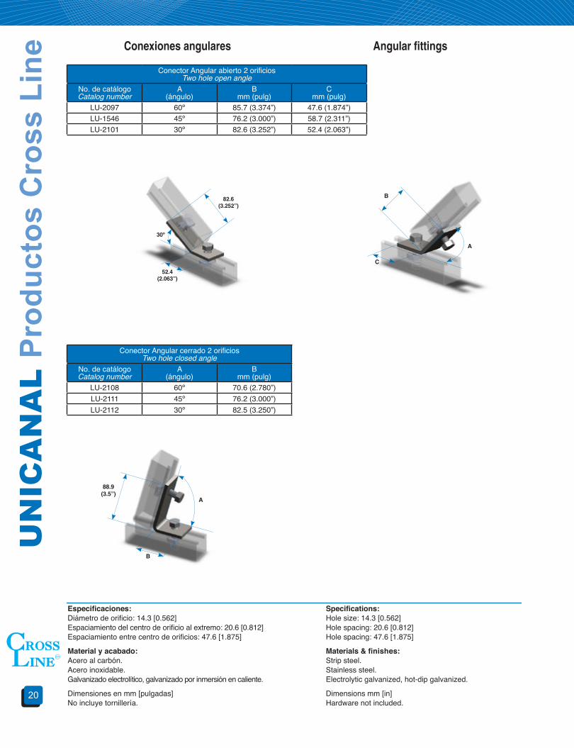
Angular fittingsConexiones angulares
Conector Angular abierto 2 orificiosTwo hole open angle
No. de catálogoCatalog number
A(ángulo)
Bmm (pulg)
Cmm (pulg)
LU-2097 60º 85.7 (3.374”) 47.6 (1.874”)LU-1546 45º 76.2 (3.000”) 58.7 (2.311”)LU-2101 30º 82.6 (3.252”) 52.4 (2.063”)
Conector Angular cerrado 2 orificiosTwo hole closed angle
No. de catálogoCatalog number
A(ángulo)
Bmm (pulg)
LU-2108 60º 70.6 (2.780”)LU-2111 45º 76.2 (3.000”)LU-2112 30º 82.5 (3.250”)
Especificaciones:Diámetro de orificio: 14.3 [0.562]Espaciamiento del centro de orificio al extremo: 20.6 [0.812]Espaciamiento entre centro de orificios: 47.6 [1.875]
Material y acabado:Acero al carbón.Acero inoxidable.Galvanizado electrolítico, galvanizado por inmersión en caliente.
Dimensiones en mm [pulgadas]No incluye tornillería.
Specifications:Hole size: 14.3 [0.562]Hole spacing: 20.6 [0.812]Hole spacing: 47.6 [1.875]
Materials&finishes:Strip steel.Stainless steel.Electrolytic galvanized, hot-dip galvanized.
Dimensions mm [in]Hardware not included.
88.9(3.5”)
A
A
B
B
C
82.6 (3.252”)
30º
52.4 (2.063”)
21
UN
IST
RU
T C
ross
Lin
e P
rodu
cts
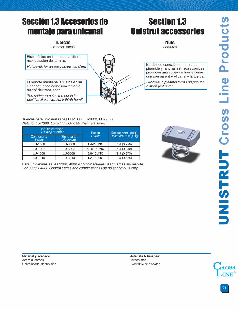
NutsFeatures
Sección 1.3 Accesorios de montaje para unicanal
Section 1.3Unistrut accessories
TuercasCaracterísticas
Bordes de conexión en forma de pirámide y ranuras estriadas cónicas, producen una conexión fuerte como una prensa entre el canal y la tuerca.Grooves in pyramid form and grip for a strongest union.
Bisel cónico en la tuerca, facilita la manipulación del tornillo.Nut bevel, for an easy screw handling
El resorte mantiene la tuerca en su lugar actuando como una “tercera mano” del trabajador.The spring remains the nut in its position like a “worker’s thirth hand”.
Material y acabado:Acero al carbónGalvanizado electrolítico
Materials&finishes:Carbon steelElectrolitic zinc coated
Para unicanales series 3300, 4000 y combinaciones usar tuercas sin resorte.For 3300 y 4000 unistrut series and combinations use no spring nuts only.
Tuercas para unicanal series LU-1000, LU-2000, LU-5500.Nuts for LU-1000, LU-2000, LU-5500 channels series.
No. de catálogoCatalog number Rosca
ThreadEspesor mm (pulg)
Thickness mm (pulg)Con resorteSpring
Sin resorteNo spring
LU-1006 LU-3006 1/4-20UNC 6.4 (0.250)LU-1007 LU-3007 5/16-18UNC 6.4 (0.250)LU-1008 LU-3008 3/8-16UNC 9.5 (0.375)LU-1010 LU-3010 1/2-13UNC 9.5 (0.375)
UN
ICA
NA
L Pr
oduc
tos
Cro
ss L
ine
22
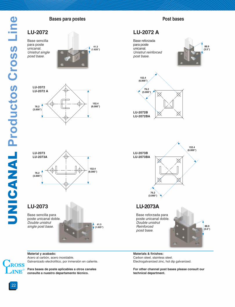
Post basesBases para postes
LU-2072Base sencilla para poste unicanal.Unistrut singleposd base.
LU-2072 ABase reforzada para poste unicanal.Unistrut reinforcedpost base.
Material y acabado:Acero al carbón, acero inoxidable.Galvanizado electrolítico, por inmersión en caliente.
Para bases de poste aplicables a otros canales consulte a nuestro departamento técnico.
Materials&finishes:Carbon steel, stainless steel.Electrogalvanized zinc, hot dip galvanized.
Forotherchannelpostbasespleaseconsultourtechnicaldepartment.
LU-2073Base sencilla para poste unicanal doble.Double unistrut single post base.
41.3 (1.625”)
41.3 (1.625”)
88.9(3.5”)
152.4 (6.000”)
152.4 (6.000”)
76.2 (3.000”)
76.2 (3.000”)
LU-2073ABase reforzada para poste unicanal doble.Double unistrut Reinforcedposd base.
88.9(3.5”)
152.4 (6.000”)
152.4 (6.000”)
76.2 (3.000”)
76.2 (3.000”)
LU-2072LU-2072 A
LU-2073LU-2073A
LU-2073BLU-2073BA
LU-2072BLU-2072BA

23
UN
IST
RU
T C
ross
Lin
e P
rodu
cts Unistrut bracketMénsulas para unicanal
Ménsulas de canal sencillo y doble emsamble tipo pared.Single and double unistrut bracket wall type assembly
No. de catálogoCatalog number
CanalChannel
Altura AHigh A
LU-1075 LU-1000/LU-3301 149.2 (5.875)LU-1593 LU-1001 190.5 (7.5)LU-1076 LU-3300 128.6 (5.06)LU-1077 LU-5500 169.8 (6.68)
LU-1077A LU-5501 231.7 (9.12)
Ménsulas de unión (no carga cantiliver)Union bracket (not for strength)
No. de catálogoCatalog number Ancho de
CharolaTray width
LongitudLenght A
Carga uniformeUniform loadRanura superior
Lips upRanura inferior
Lips downLU-2511 LU-2511A 101.6 (4) 152.4 (6) 484 kgLU-2513 LU-2513A 152.4 (6) 203.2 (8) 403 kgLU-2512 LU-2512A 228.6 (9) 279.4 (11) 282 kgLU-2514 LU-2514A 304.8 (12) 355.6 (14) 221 kgLU-2515 LU-2515A 457.2 (18) 508.0 (20) 161 kgLU-2519 LU-2519A 508.0 (20) 558.8 (22) 140 kgLU-2516 LU-2516A 609.6 (24) 660.4 (26) 115 kgLU-2517 LU-2517A 762.0 (30) 812.8 (32) 100 kgLU-2518 LU-2518A 914.4 (36) 965.2 (38 85 kg
Ménsulas de canal ensamble tipo pestañaUnistrut bracket lift type assembly
AA
A
No. de catálogoCatalog number
Ancho de charolaTray Width
LongitudLenght A
Carga uniformeUniform load
LU-1000 LU-2000LU-2539 101.6 (4) 152.4 (6) 408 kg 363 kgLU-2540 152.4 (6) 203.2 (8) 340 Kg 302 KgLU-2541 228.6 (9) 279.4 (11) 238 Kg 211 KgLU-2542 304.8 (12) 355.6 (14) 187 Kg 166 Kg
LU-2543 A 457.2 (18) 508.0 (20) 453 Kg 403 KgLU-2544 A 609.6 (24) 660.4 (26) 325 Kg 289 KgLU-2545 A 762.0 (30) 812.8 (32) 282 Kg 250 KgLU-2546 A 914.4 (36) 965.2 (38) 240 Kg 213 Kg 165.1
(6.500)
Material y acabado:Acero al carbón, acero inoxidable.Galvanizado electrolítico, por inmersión en caliente.Dimensiones mm (pulg).
Materials&finishes:Carbon steel, stainless steel.Finishes: electrogalvanized zinc, hot dip galvanized.Dimensions mm (in).
A
A
123.8(4.875)
121(4.750)
121(4.750)
88.9(3.500)
UN
ICA
NA
L Pr
oduc
tos
Cro
ss L
ine
24
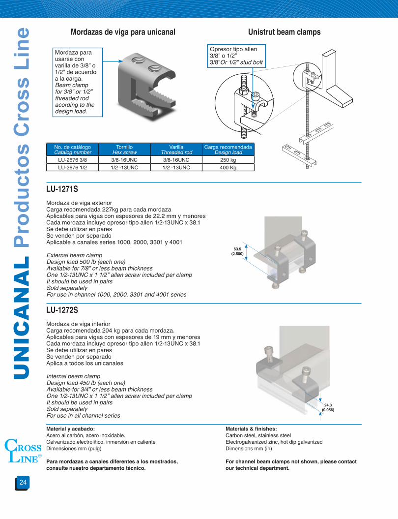
Unistrut beam clampsMordazas de viga para unicanal
Mordaza para usarse con varilla de 3/8” o 1/2” de acuerdo a la carga.Beam clamp for 3/8” or 1/2” threaded rod acording to the design load.
Opresor tipo allen 3/8” o 1/2”3/8”Or 1/2” stud bolt
LU-1271S
Mordaza de viga exteriorCarga recomendada 227kg para cada mordazaAplicables para vigas con espesores de 22.2 mm y menoresCada mordaza incluye opresor tipo allen 1/2-13UNC x 38.1Se debe utilizar en paresSe venden por separadoAplicable a canales series 1000, 2000, 3301 y 4001
External beam clampDesign load 500 lb (each one)Available for 7/8” or less beam thicknessOne 1/2-13UNC x 1 1/2” allen screw included per clampIt should be used in pairsSold separatelyFor use in channel 1000, 2000, 3301 and 4001 series
No. de catálogoCatalog number
TornilloHex screw
Varilla Threaded rod
Carga recomendadaDesign load
LU-2676 3/8 3/8-16UNC 3/8-16UNC 250 kgLU-2676 1/2 1/2 -13UNC 1/2 -13UNC 400 Kg
LU-1272S
Mordaza de viga interiorCarga recomendada 204 kg para cada mordaza.Aplicables para vigas con espesores de 19 mm y menoresCada mordaza incluye opresor tipo allen 1/2-13UNC x 38.1Se debe utilizar en paresSe venden por separadoAplica a todos los unicanales
Internal beam clampDesign load 450 lb (each one)Available for 3/4” or less beam thicknessOne 1/2-13UNC x 1 1/2” allen screw included per clampIt should be used in pairsSold separatelyFor use in all channel series
Material y acabado:Acero al carbón, acero inoxidable.Galvanizado electrolítico, inmersión en calienteDimensiones mm (pulg)
Paramordazasacanalesdiferentesalosmostrados,consulte nuestro departamento técnico.
Materials&finishes:Carbon steel, stainless steelElectrogalvanized zinc, hot dip galvanizedDimensions mm (in)
Forchannelbeamclampsnotshown,pleasecontactourtechnicaldepartment.
24.3(0.956)
63.5 (2.500)
25
UN
IST
RU
T C
ross
Lin
e P
rodu
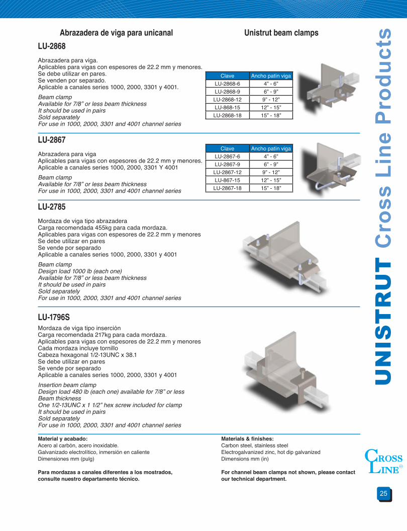
ctsUnistrut beam clampsAbrazadera de viga para unicanal
LU-2868
Abrazadera para viga.Aplicables para vigas con espesores de 22.2 mm y menores.Se debe utilizar en pares.Se venden por separado.Aplicable a canales series 1000, 2000, 3301 y 4001.Beam clampAvailable for 7/8” or less beam thicknessIt should be used in pairs Sold separatelyFor use in 1000, 2000, 3301 and 4001 channel series
LU-2785
Mordaza de viga tipo abrazaderaCarga recomendada 455kg para cada mordaza.Aplicables para vigas con espesores de 22.2 mm y menoresSe debe utilizar en paresSe vende por separadoAplicable a canales series 1000, 2000, 3301 y 4001Beam clampDesign load 1000 lb (each one)Available for 7/8” or less beam thicknessIt should be used in pairsSold separatelyFor use in 1000, 2000, 3301 and 4001 channel series
LU-2867
Abrazadera para vigaAplicables para vigas con espesores de 22.2 mm y menores.Aplicable a canales series 1000, 2000, 3301 Y 4001Beam clampAvailable for 7/8” or less beam thicknessFor use in 1000, 2000, 3301 and 4001 channel series
LU-1796SMordaza de viga tipo inserciónCarga recomendada 217kg para cada mordaza.Aplicables para vigas con espesores de 22.2 mm y menoresCada mordaza incluye tornilloCabeza hexagonal 1/2-13UNC x 38.1Se debe utilizar en paresSe vende por separadoAplicable a canales series 1000, 2000, 3301 y 4001Insertion beam clampDesign load 480 lb (each one) available for 7/8” or less Beam thicknessOne 1/2-13UNC x 1 1/2” hex screw included for clampIt should be used in pairsSold separatelyFor use in 1000, 2000, 3301 and 4001 channel series
Material y acabado:Acero al carbón, acero inoxidable.Galvanizado electrolítico, inmersión en calienteDimensiones mm (pulg)
Paramordazasacanalesdiferentesalosmostrados,consulte nuestro departamento técnico.
Materials&finishes:Carbon steel, stainless steelElectrogalvanized zinc, hot dip galvanizedDimensions mm (in)
Forchannelbeamclampsnotshown,pleasecontactourtechnicaldepartment.
Clave Ancho patín vigaLU-2868-6 4” - 6”LU-2868-9 6” - 9”
LU-2868-12 9” - 12”LU-868-15 12” - 15”
LU-2868-18 15” - 18”
Clave Ancho patín vigaLU-2867-6 4” - 6”LU-2867-9 6” - 9”
LU-2867-12 9” - 12”LU-867-15 12” - 15”
LU-2867-18 15” - 18”
UN
ICA
NA
L Pr
oduc
tos
Cro
ss L
ine
26
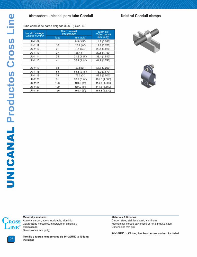
Unistrut Conduit clampsAbrazadera unicanal para tubo Conduit
No. de catálogoCatalog number
Diam nominalDesignacion
Diam extTubo conduit
mm (pulg)Tubo mm (pulg)LU-1109 9.5 (3/8”) 14.7 (0.580)LU-1111 16 12.7 (½”) 17.9 (0.700)LU-1112 21 19.1 (3/4”) 23.4 (0.920)LU-1113 27 25.4 (1”) 29.5 (1.160)LU-1114 35 31.8 (1 ¼”) 38.4 (1.510)LU-1115 41 38.1 (1 ½”) 44.2 (1.740)
LU-1117 53 50.8 (2”) 55.8 (2.200)LU-1118 63 63.5 (2 ½”) 73.0 (2.870)LU-1119 78 76.2 (3”) 88.9 (3.500)LU-1120 91 88.9 (3 ½”) 101.6 (4.000)LU-1121 103 101.6 (4”) 114.3 (4.500)LU-1123 129 127.0 (5”) 141.3 (5.560)LU-1124 155 152.4 (6”) 168.3 (6.630)
Material y acabado:Acero al carbón, acero inoxidable, aluminioGalvanizado mecánico, inmersión en caliente y tropicalizado.Dimensiones mm (pulg)
Tornilloytuercahexagonalesde1/4-20UNC x 19 long incluidos
Materials&finishes:Carbon steel, stainless steel, aluminumMechanical, electro galvanized or hot dip galvanized Dimensions mm (in)
1/4-20UNCx3/4longhexheadscrewandnutincluded
Tubo conduit de pared delgada (E.M.T.) Ced. 40
27
WIR
EW
AY
Cro
ss L
ine
Pro
duct
s
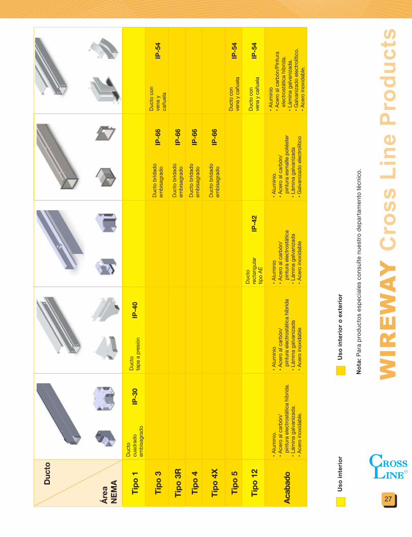
Duc
to
Área
N
EMA
Tipo
1Du
cto
cuad
rado
em
bisa
grad
oIP
-30
Duct
o
tapa
a p
resió
nIP
-40
Tipo
3Du
cto
brid
ado
embi
sagr
ado
IP-6
6Du
cto
con
vena
y
cañu
ela
IP-5
4
Tipo
3R
Duct
o br
idad
o em
bisa
grad
oIP
-66
Tipo
4Du
cto
brid
ado
embi
sagr
ado
IP-6
6
Tipo
4X
Duct
o br
idad
o em
bisa
grad
oIP
-66
Tipo
5Du
cto
con
vena
y c
añue
laIP
-54
Tipo
12
Duct
o re
ctan
gula
rtip
o AE
IP-4
2Du
cto
con
vena
y c
añue
laIP
-54
Acab
ado
• Alu
min
io.
• Ace
ro a
l car
bón/
pi
ntur
a el
ectro
stát
ica
híbr
ida.
• L
ámin
a ga
lvan
izada
.• A
cero
inox
idab
le.
• Alu
min
io• A
cero
al c
arbó
n/
pint
ura
elec
trost
átic
a hí
brid
a• L
ámin
a ga
lvan
izada
• Ace
ro in
oxid
able
• Alu
min
io• A
cero
al c
arbó
n/
pint
ura
elec
trost
átic
a• L
ámin
a ga
lvan
izada
• Ace
ro in
oxid
able
• Alu
min
io.
• Ace
ro a
l car
bón/
pi
ntur
a es
mal
te p
olié
ster
• Lám
ina
galv
aniza
da• G
alva
niza
do e
lect
rolít
ico
• Alu
min
io• A
cero
al c
arbó
n/Pi
ntur
a el
ectro
stát
ica
híbr
ida.
• L
ámin
a ga
lvan
izada
.• G
alva
niza
do e
lect
rolít
ico.
• Ace
ro in
oxid
able
.
Not
a: P
ara
prod
ucto
s es
peci
ales
con
sulte
nue
stro
dep
arta
men
to té
cnic
o.
Uso
inte
rior
Uso
inte
rior
o e
xter
ior
Uso
inte
rior
Uso
inte
rior
o e
xter
ior
Not
a: P
ara
prod
ucto
s es
peci
ales
con
sulte
nue
stro
dep
arta
men
to té
cnic
o.

DU
CT
O P
rodu
ctos
Cro
ss L
ine
28
Producto de la experiencia de más de 30 años dise-ñando y fabricando sistemas de soportería para ca-bles es esta nuestra línea de DUCTOS CERRADOS que CROSS LINE pone a su disposición.
Los ductos cerrados de CROSS LINE cumplen con los más altos estándares de calidad y diseño para cumplir con sus necesidades de instalación de ca-bles en lugares en los cuales existe la presencia de agentes externos dañinos como son químicos agresivos, proyecciones de objetos, circulación de vehículos, afluencia de animales extraños al siste-ma, etc.
Diseñados para cubrir las necesidades de áreas descritas por las normas nacionales e internacio-nales, tipos NEMA desde 1 hasta 12. Con grados IP desde 30 hasta 67.
CROSS LINE como empresa líder en el mercado, ha desarrollado una nueva línea de ducto cuadrado, pensando en los nuevos requerimientos del cliente. Esta nueva línea representa la oferta de uso comer-cial estándar de ducto cuadrado para aplicaciones de distribución y protección de cableado. Siendo más económico frente a otras opciones del merca-do, manteniendo la misma calidad y diseño óptimo para instalaciones de ensamble rápido.
Our WIREWAY line is product of 30 years of inves-tigation, design, manufacturing cable support sys-tems, to comply with the installation in areas were aggressive chemicals, object projections, machines and animals are present.
Those wireways comply with national and interna-tional standards for NEMA areas through 1 to 12 or through 30 to 67 IP protection grade.
Sección 2 Ductos Section 2 Wireway
Uso exteriorProtección contra las siguientes
condiciones ambientalesTipodeenvolvente
3 3R 3S 4 4X 6 6PContacto incidental con el gabinete x x x x x x xLluvia, nieve, granizo x x x x x x xGranizo xPolvoso x x x x x xEscurrimiento en las canalizaciones x x x xAgentes corrosivos x xInmersión temporal ocasional x xInmersión prolongada ocasional x
Uso interiorProtección contra las siguientes
condiciones ambientalesTipodeenvolvente
1 2 4 4X 5 6 6P 12Contacto incidental con el gabinete x x x x x x x xAcumulación de suciedad x x x x x x x xCaída de líquidos y goteo ligero x x x x x x xPolvo circulante, pelusa y fibras x x x x xDepósito de polvo, pelusas y fibras x x x x x xEscurrimiento y salpicaduras de agua x x x xFiltración aceite y líquido refrigerante xSalpicaduras de aceite y refrigeranteAgentes corrosivos xInmersión temporal ocasional x xInmersión prolongada ocasional x

29
WIR
EW
AY
Cro
ss L
ine
Pro
duct
s
Grado de protección contra objetos sólidos Descripción Grado de protección
contra objetos liquidos Descripción
0 Grado inherente de protección 0 Grado inherente de
protección
1Protegido contra objetos
sólidos de 50 mm de largo (ej. contacto accidental
con la mano)1 Protegido contra gotas de
agua cayendo
2Protección contra objetos sólidos de 12 mm de largo (ejem. contacto accidental
con los dedos)2
Protegido contra gotas de agua cayendo a una
inclinación de 15º respecto a la vertical
3Protegido contra objetos
sólidos de 2.5 mm de largo (ejem. herramientas y
alambres)3
Protegido contra gotas de agua cayendo a una
inclinación de 60º respecto a la vertical
4Protegido contra objetos
solidos de 1 mm de largo (ej. herramientas y
alambres4
Protegido contra salpicaduras de agua
desde todas las direcciones
5Protección contra
cantidades de polvo que pudieran interferir con una
operación satisfactoria5
Protegido contra agua a baja presión desde todas
las direcciones
6 Completamente protegido contra el ingreso de polvo 6
Protegido contra agua a alta presión en cualquier
dirección
- - 7Protegido contra la
inmersión entre 15 cm y 1 m
- - 8Protegido contra largos
periodos de inmersión bajo presión
Clasificación IP (XX)
La siguiente tabla resume la nomenclatura IP para dar una idea acerca de la clasificación de acuerdo con la protección provista por los ductos y/o gabinetes para equipos eléctricos.
Grado de protección contra objetos sólidosGrado de protección contra líquidosInternational Protection
IP-X X
DU
CT
O P
rodu
ctos
Cro
ss L
ine
30
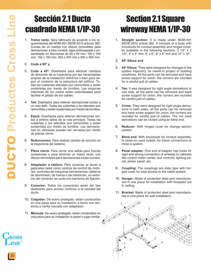
1. Tramo recto: Sera fabricado de acuerdo a los re-querimientos del NOM-001 SEDE-2012 artículo 362. Consta de un cuerpo con discos removibles para derivaciones a tubo conduit, tapa embisagrada y en-samblada; en Secciones de 65 x 65 mm, 100 x 100 mm, 150 x 150 mm, 203 x 203 mm y 305 x 305 mm.
2. Codo a 90° y
3. Codo a 45°: Diseñados para efectuar cambios de dirección de la trayectoria por las necesidades propias de la instalación eléctrica o bien para se-guir el contorno de la estructura del edificio. To-das las cubiertas laterales son removibles y están sostenidas por medio de tornillos. Las esquinas interiores de los codos están redondeadas para facilitar el jalado de los cables.
4. Tee: Diseñados para obtener derivaciones rectas a un solo lado. Todas las cubiertas y los laterales son removibles y están sostenidas por medio de tornillos.
5. Equis: Diseñados para obtener derivaciones rec-tas a ambos lados de la ruta principal. Todas las cubiertas y los laterales son removibles y están sostenidas por medio de tornillos. Las derivacio-nes no utilizadas pueden ser cerradas por medio de placas cierre.
6. Reducciones: Para realizar cambio de sección en la trayectoria del sistema.
7. Placa cierre: Para cerrar una salida para futuras conexiones o para terminar un tramo recto, con discos removibles para derivaciones a tubo conduit.
8. Adaptador a tablero: Para conectar el ducto a gabinetes tales como centros de control de moto-res, controles de máquinas herramientas, tableros de alumbrado, de fuerza o de transición, un extre-mo del conector se surte con barrenos de fijación.
9. Conector: Todos los conectores serán del tipo deslizante para acceso continuo a la cavidad del ducto.
10. Colgador: De acero protegido, están construidos en una pieza para su instalación a techo con ten-sores o varilla roscada con adaptador.
11. Ménsula: De acero protegido, están construidos en una pieza para su instalación a pared o lugar similar.
1. Straight section: It is made under NOM-001 SEDE-2012 article 362. It consists of a body with knockouts for conduit assembly and hinged cover, its available in the following sections: 2 1/2” x 2 1/2”, 4” x 4” mm, 6” x 6”, 8” x 8” mm and 12” x 12”.
2. 90° Elbow and
3. 45° Elbow: They were designed for changes in the system trajectory, for needs in project or building conditions. All the parts can be removed and have screw support for union, the corners are rounded for a careful pull of cables.
4. Tee: It was designed for right angle derivations to one side, all the parts can be removed and have screw support for union, the corners are rounded for careful pull of cables.
5. Cross: They were designed for right angle deriva-tions to both sides, all the parts can be removed and have screw support for union, the corners are rounded for careful pull of cables. The not used derivations can be closed using an blind end.
6. Reducer: With hinged cover for change section system.
7. Blind end: With knockouts for conduit assembly, to close no used outlets, for future connections or close a system.
8. Panel adapter: One end of adapter has holes for rigid and strong connection of wireway to cabinets like control motor center, tool controls, lighting pa-nel, power panel, etc.
9. Coupling: The couplings are slide type with hin-ged cover for total access to the cable system.
10. Hanger: Made of protected steel and manufactu-red in one piece for installation with threaded rod in ceiling.
11. Bracket: Made of protected steel and manufactu-red in one piece for wall installation.
Sección 2.1 Ducto cuadrado NEMA 1/IP-30
Section 2.1 Square wireway NEMA 1/IP-30
31
WIR
EW
AY
Cro
ss L
ine
Pro
duct
s
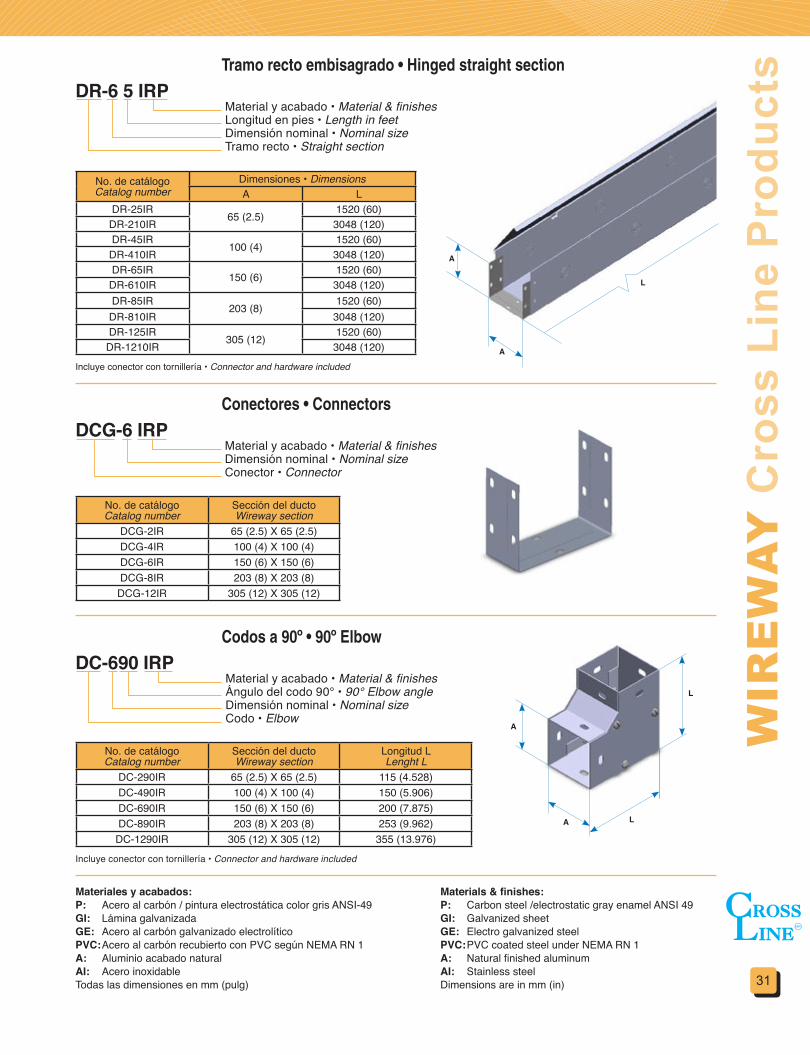
Material y acabado • Material & finishesLongitud en pies • Length in feetDimensión nominal • Nominal sizeTramo recto • Straight section
Material y acabado • Material & finishesDimensión nominal • Nominal sizeConector • Connector
Tramo recto embisagrado • Hinged straight section
No. de catálogoCatalog number
Dimensiones • DimensionsA L
DR-25IR 65 (2.5) 1520 (60)DR-210IR 3048 (120)DR-45IR 100 (4) 1520 (60)
DR-410IR 3048 (120)DR-65IR 150 (6) 1520 (60)
DR-610IR 3048 (120)DR-85IR 203 (8) 1520 (60)
DR-810IR 3048 (120)DR-125IR 305 (12) 1520 (60)
DR-1210IR 3048 (120)
DR-6 5 IRP
No. de catálogoCatalog number
Sección del ductoWireway section
DCG-2IR 65 (2.5) X 65 (2.5)DCG-4IR 100 (4) X 100 (4)DCG-6IR 150 (6) X 150 (6)DCG-8IR 203 (8) X 203 (8)
DCG-12IR 305 (12) X 305 (12)
Materiales y acabados:P: Acero al carbón / pintura electrostática color gris ANSI-49GI: Lámina galvanizadaGE: Acero al carbón galvanizado electrolíticoPVC: Acero al carbón recubierto con PVC según NEMA RN 1A: Aluminio acabado naturalAI: Acero inoxidableTodas las dimensiones en mm (pulg)
Materials&finishes:P: Carbon steel /electrostatic gray enamel ANSI 49GI: Galvanized sheetGE: Electro galvanized steelPVC: PVC coated steel under NEMA RN 1A: Natural finished aluminumAI: Stainless steelDimensions are in mm (in)
Incluye conector con tornillería • Connector and hardware included
Conectores • Connectors
Incluye conector con tornillería • Connector and hardware included
No. de catálogoCatalog number
Sección del ductoWireway section
Longitud LLenght L
DC-290IR 65 (2.5) X 65 (2.5) 115 (4.528)DC-490IR 100 (4) X 100 (4) 150 (5.906)DC-690IR 150 (6) X 150 (6) 200 (7.875)DC-890IR 203 (8) X 203 (8) 253 (9.962)
DC-1290IR 305 (12) X 305 (12) 355 (13.976)
DC-690 IRPMaterial y acabado • Material & finishesÁngulo del codo 90° • 90° Elbow angleDimensión nominal • Nominal sizeCodo • Elbow
Codos a 90º • 90º Elbow
DCG-6 IRP
A
A
A
A
L
L
L
DU
CT
O P
rodu
ctos
Cro
ss L
ine
32
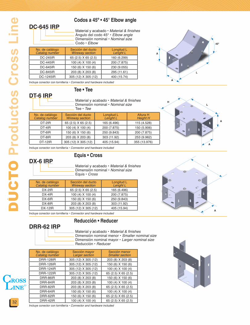
Codos a 45º • 45° Elbow angleDC-645 IRP
Material y acabado • Material & finishesÁngulo del codo 45° • Elbow angleDimensión nominal • Nominal sizeCodo • Elbow
No. de catálogoCatalog number
Sección del ductoWireway section
Longitud LLenght L
DC-245IR 65 (2.5) X 65 (2.5) 160 (6.299)DC-445IR 100 (4) X 100 (4) 200 (7.875)DC-645IR 150 (6) X 150 (6) 230 (9.055)DC-845IR 203 (8) X 203 (8) 295 (11.61)
DC-1245IR 305 (12) X 305 (12) 400 (15.74)Incluye conector con tornillería • Connector and hardware included
Tee • TeeDT-6 IRP
Material y acabado • Material & finishesDimensión nominal • Nominal sizeTee • Tee
No. de catálogoCatalog number
Sección del ductoWireway section
Longitud LLenght L
Altura HHeight H
DT-2IR 65 (2.5) X 65 (2.5) 165 (6.496) 115 (4.528)DT-4IR 100 (4) X 100 (4) 200 (7.875) 150 (5.906)DT-6IR 150 (6) X 150 (6) 250 (9.843) 200 (7.875)DT-8IR 203 (8) X 203 (8) 303 (11.92) 253 (9.962)
DT-12IR 305 (12) X 305 (12) 405 (15.94) 355 (13.976)Incluye conector con tornillería • Connector and hardware included
Equis • CrossDX-6 IRP
Material y acabado • Material & finishesDimensión nominal • Nominal sizeEquis • Cross
Incluye conector con tornillería • Connector and hardware included
No. de catálogoCatalog number
Sección del ductoWireway section
Longitud LLenght L
DX-2IR 65 (2.5) X 65 (2.5) 165 (6.496)DX-4IR 100 (4) X 100 (4) 200 (7.875)DX-6IR 150 (6) X 150 (6) 250 (9.843)DX-8IR 203 (8) X 203 (8) 303 (11.92)
DX-12IR 305 (12) X 305 (12) 405 (15.94)
Reducción • ReducerDRR-62 IRP
Material y acabado • Material & finishesDimensión nominal menor • Smaller nominal sizeDimensión nominal mayor • Larger nominal sizeReducción • Reducer
Incluye conector con tornillería • Connector and hardware included
No. de catálogoCatalog number
Sección mayorLarger section
Sección menorSmaller section
DRR-128IR 305 (12) X 305 (12) 203 (8) X 203 (8)DRR-126IR 305 (12) X 305 (12) 150 (6) X 150 (6)DRR-124IR 305 (12) X 305 (12) 100 (4) X 100 (4)DRR-122IR 305 (12) X 305 (12) 65 (2.5) X 65 (2.5)DRR-86IR 203 (8) X 203 (8) 150 (6) X 150 (6)DRR-84IR 203 (8) X 203 (8) 100 (4) X 100 (4)DRR-82IR 203 (8) X 203 (8) 65 (2.5) X 65 (2.5)DRR-64IR 150 (6) X 150 (6) 100 (4) X 100 (4)DRR-62IR 150 (6) X 150 (6) 65 (2.5) X 65 (2.5)DRR-42IR 100 (4) X 100 (4) 65 (2.5) X 65 (2.5)
A
A
A
A
H
A
L
L
L
45º
33
WIR
EW
AY
Cro
ss L
ine
Pro
duct
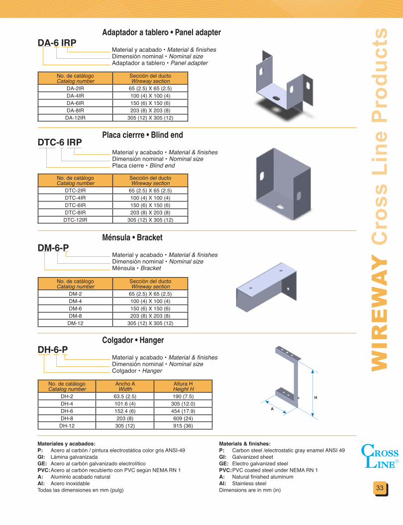
sAdaptador a tablero • Panel adapterDA-6 IRP
Material y acabado • Material & finishesDimensión nominal • Nominal sizeAdaptador a tablero • Panel adapter
No. de catálogoCatalog number
Sección del ductoWireway section
DA-2IR 65 (2.5) X 65 (2.5)DA-4IR 100 (4) X 100 (4)DA-6IR 150 (6) X 150 (6)DA-8IR 203 (8) X 203 (8)
DA-12IR 305 (12) X 305 (12)
Placa cierrre • Blind endDTC-6 IRP
Material y acabado • Material & finishesDimensión nominal • Nominal sizePlaca cierre • Blind end
No. de catálogoCatalog number
Sección del ductoWireway section
DTC-2IR 65 (2.5) X 65 (2.5)DTC-4IR 100 (4) X 100 (4)DTC-6IR 150 (6) X 150 (6)DTC-8IR 203 (8) X 203 (8)
DTC-12IR 305 (12) X 305 (12)
Ménsula • BracketDM-6-P
Material y acabado • Material & finishesDimensión nominal • Nominal sizeMénsula • Bracket
No. de catálogoCatalog number
Sección del ductoWireway section
DM-2 65 (2.5) X 65 (2.5)DM-4 100 (4) X 100 (4)DM-6 150 (6) X 150 (6)DM-8 203 (8) X 203 (8)
DM-12 305 (12) X 305 (12)
Colgador • Hanger
Material y acabado • Material & finishesDimensión nominal • Nominal sizeColgador • Hanger
No. de catálogoCatalog number
Ancho AWidth
Altura HHeight H
DH-2 63.5 (2.5) 190 (7.5)DH-4 101.6 (4) 305 (12.0)DH-6 152.4 (6) 454 (17.9)DH-8 203 (8) 609 (24)
DH-12 305 (12) 915 (36)
Materiales y acabados:P: Acero al carbón / pintura electrostática color gris ANSI-49GI: Lámina galvanizadaGE: Acero al carbón galvanizado electrolíticoPVC: Acero al carbón recubierto con PVC según NEMA RN 1A: Aluminio acabado naturalAI: Acero inoxidableTodas las dimensiones en mm (pulg)
Materials&finishes:P: Carbon steel /electrostatic gray enamel ANSI 49GI: Galvanized sheetGE: Electro galvanized steelPVC: PVC coated steel under NEMA RN 1A: Natural finished aluminumAI: Stainless steelDimensions are in mm (in)
A
H
DH-6-P
DU
CT
O P
rodu
ctos
Cro
ss L
ine
34
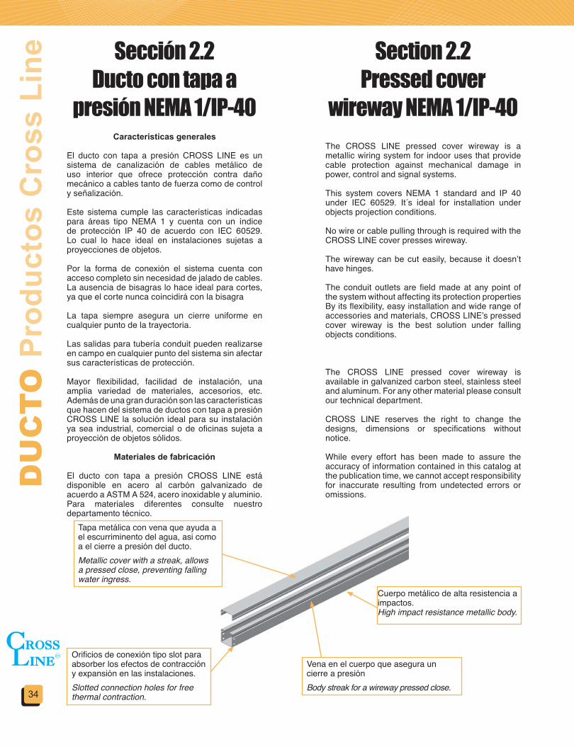
Características generales
El ducto con tapa a presión CROSS LINE es un sistema de canalización de cables metálico de uso interior que ofrece protección contra daño mecánico a cables tanto de fuerza como de control y señalización.
Este sistema cumple las características indicadas para áreas tipo NEMA 1 y cuenta con un índice de protección IP 40 de acuerdo con IEC 60529. Lo cual lo hace ideal en instalaciones sujetas a proyecciones de objetos.
Por la forma de conexión el sistema cuenta con acceso completo sin necesidad de jalado de cables.La ausencia de bisagras lo hace ideal para cortes, ya que el corte nunca coincidirá con la bisagra
La tapa siempre asegura un cierre uniforme en cualquier punto de la trayectoria.
Las salidas para tubería conduit pueden realizarse en campo en cualquier punto del sistema sin afectar sus características de protección.
Mayor flexibilidad, facilidad de instalación, una amplia variedad de materiales, accesorios, etc. Además de una gran duración son las características que hacen del sistema de ductos con tapa a presión CROSS LINE la solución ideal para su instalación ya sea industrial, comercial o de oficinas sujeta a proyección de objetos sólidos.
Materiales de fabricación
El ducto con tapa a presión CROSS LINE está disponible en acero al carbón galvanizado de acuerdo a ASTM A 524, acero inoxidable y aluminio. Para materiales diferentes consulte nuestro departamento técnico.
The CROSS LINE pressed cover wireway is a metallic wiring system for indoor uses that provide cable protection against mechanical damage in power, control and signal systems.
This system covers NEMA 1 standard and IP 40 under IEC 60529. It s ideal for installation under objects projection conditions.
No wire or cable pulling through is required with the CROSS LINE cover presses wireway.
The wireway can be cut easily, because it doesn’t have hinges.
The conduit outlets are field made at any point of the system without affecting its protection propertiesBy its flexibility, easy installation and wide range of accessories and materials, CROSS LINE’s pressed cover wireway is the best solution under falling objects conditions.
The CROSS LINE pressed cover wireway is available in galvanized carbon steel, stainless steel and aluminum. For any other material please consult our technical department.
CROSS LINE reserves the right to change the designs, dimensions or specifications without notice.
While every effort has been made to assure the accuracy of information contained in this catalog at the publication time, we cannot accept responsibility for inaccurate resulting from undetected errors or omissions.
Sección 2.2Ducto con tapa a
presión NEMA 1/IP-40
Section 2.2Pressed cover
wireway NEMA 1/IP-40
Tapa metálica con vena que ayuda a el escurriminento del agua, asi como a el cierre a presión del ducto.Metallic cover with a streak, allows a pressed close, preventing falling water ingress.
Orificios de conexión tipo slot para absorber los efectos de contracción y expansión en las instalaciones.Slotted connection holes for free thermal contraction.
Cuerpo metálico de alta resistencia a impactos.High impact resistance metallic body.
Vena en el cuerpo que asegura un cierre a presiónBody streak for a wireway pressed close.

35
WIR
EW
AY
Cro
ss L
ine
Pro
duct
s
H
A
Tramo recto • Straight Section
No. de catálogoCatalog number
Dimensiones • Dimensions Largo • LengthA H L
DTP-756575 (3) 65 (2.5)
75 (3)
15003000
DTP-7575DTP-15065
150 (6)65 (2.5)75 (3)
100 (4)150 (6)
DTP-15075DTP-150100DTP-150150DTP-30065
300 (12)65 (2.5)75 (3)
100 (4)150 (6)
DTP-30075DTP-300100DTP-300150
DVHTP-15075-45-GI
DTP-15075-1.5-GI
Incluye 2 conectores con tornillería • Two connectors and hardware includedEl ducto y accesorios ancho de 75 (3) solo se surte en peralte 65 (2.5) y 75 (3)
Codo horizontal a 90º • 90º horizontal elbow
No. de catálogoCatalog number
Dimensiones • DimensionsA H
DVHTP-75__-90 75 (3) 65 (2.5)75 (3)100 (4)150 (6)
DVHTP-150__-90 150 (6)DVHTP-300__-90 300 (12)
DVHTP-15075-90-GI
No. de catálogoCatalog number
Dimensiones • DimensionsA H
DVHTP-75__-45 75 (3) 65 (2.5)75 (3)
100 (4)150 (6)
DVHTP-150__-45 150 (6)DVHTP-300__-45 300 (12)
Codo horizontal a 45º • 45º horizontal elbow
Materiales y acabados:GI: Lámina galvanizadaP: Acero al carbón / Pintura electrostática gris ANSI-49A: Aluminio acabado naturalAI: Acero inoxidable Todas las dimensiones en mm (pulg)
Materials&finishes:GI: Galvanized sheetP: Carbon steel / Electrostatic gray enamel ANSI-49A: Natural finished aluminumAI: Stainless steel All dimensions are in mm (in)
H
AR100
(4)
H
A R100(4)
Incluye 2 conectores con tornillería • Two connectors and hardware includedEl ducto y accesorios ancho de 75 (3) solo se surte en peralte 65 (2.5) y 75 (3)
Incluye 2 conectores con tornillería • Two connectors and hardware includedEl ducto y accesorios ancho de 75 (3) solo se surte en peralte 65 (2.5) y 75 (3)
Material y acabado • Material & finishesÁngulo de la curva 90º • Elbow angle 90ºPeralte • HeightAncho • WidthCodo horizontal • Horizontal elbow
Material y acabado • Material & finishesLongitud en metros • Length in metersDisponible en • Available in 1.5 y 3.0 m.Peralte • HeightAncho • WidthTramo recto • Straight section
L
Material y acabado • Material & finishesÁngulo de la curva 45º • Elbow angle 45ºPeralte • HeightAncho • WidthCodo horizontal • Horizontal elbow

DU
CT
O P
rodu
ctos
Cro
ss L
ine
36
H
R100(4)
A
No. de catálogoCatalog number
Dimensiones• DimensionsA B L H
DTHTP-75__ 75 (3) 205 (8) 335 (13.19) 65 (2.5)75 (3)
100 (4)150 (6)
DTHTP-150__ 150 (6) 280 (11) 410 (16.14)DTHTP-300__ 300 (12) 430 (17) 560 (22.04)
DTHTP-15075-GI
Incluye 2 conectores con tornillería • Two connectors and hardware includedEl ducto y accesorios ancho de 75 (3) solo se surte en peralte 65 (2.5) y 75 (3)
Tee horizontal • Horizontal tee
Material y acabado • Material & finishesPeralte • HeightAncho • WidthTee horizontal • Horizontal tee
Equis horizontal • Horizontal cross
Reducción recta • Straicht reducer
Codo vertical interior a 90º • 90º Inside vertical elbow
No. de catálogoCatalog number
Dimensiones • DimensionsA L H
DXHTP-7575 75 (3) 335 (13.19) 65 (2.5)75 (3)
100 (4)150 (6)
DXHTP-15075 150 (6) 410 (16.14)DXHTP-30075 300 (12) 560 (22.04)
Incluye 2 conectores con tornillería • Two connectors and hardware includedEl ducto y accesorios ancho de 75 (3) solo se surte en peralte 65 (2.5) y 75 (3)
Incluye 2 conectores con tornillería • Two connectors and hardware includedEl ducto y accesorios ancho de 75 (3) solo se surte en peralte 65 (2.5) y 75 (3)
Incluye 2 conectores con tornillería • Two connectors and hardware includedEl ducto y accesorios ancho de 75 (3) solo se surte en peralte 65 (2.5) y 75 (3)
DXHTP-15075-GIMaterial y acabado • Material & finishesPeralte • HeightAncho • WidthEquis horizontal • Horizontal cross
No. de catálogoCatalog number
Dimensiones • DimensionsA H
DVITP-75__-90 75 (3) 65 (2.5)75 (3)
100 (4)150 (6)
DVITP-150__-90 150 (6)DVITP-300__-90 300 (12)
DRLTP-15075-GIMaterial y acabado • Material & finishesAncho menor • Smaller widthAncho mayor • Larger widthReducción recta • Straight reducer
No. de catálogoCatalog number
Ancho mayorLarger widht
Ancho menorSmaller widht H
DRLTP-300150 300 (12) 150 (6) 65 (2.5)75 (3)
100 (4)150 (6)
DRLTP-30075 300 (12) 75 (3)DRLTP-15075 150 (6) 75 (3)
DVITP-15075-90-GI
H
Materiales y acabados:GI: Lámina galvanizadaP: Acero al carbón / Pintura electrostática gris ANSI-49A: Aluminio acabado naturalAI: Acero inoxidable Todas las dimensiones en mm (pulg)
Materials&finishes:GI: Galvanized sheetP: Carbon steel / Electrostatic gray enamel ANSI-49A: Natural finished aluminumAI: Stainless steel All dimensions are in mm (in)
Material y acabado • Material & finishesÁngulo de la curva 90º • Elbow angle 90ºPeralte • HeightAncho • WidthCodo vertical interior • Inside vertical elbow
H
AR100
(4)
L
A
H
R100(4) B
L
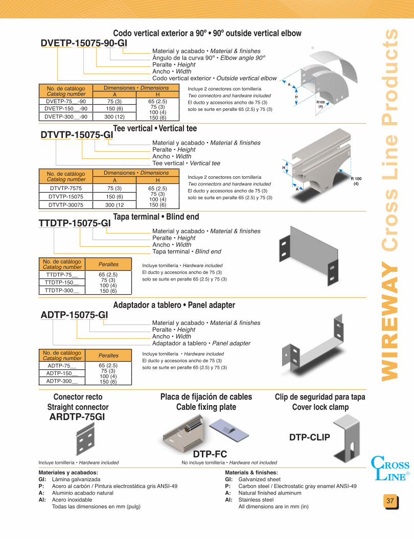
37
WIR
EW
AY
Cro
ss L
ine
Pro
duct
s
Tee vertical • Vertical tee
Tapa terminal • Blind end
Adaptador a tablero • Panel adapter
Conector rectoStraight connector
Placa de fijación de cablesCable fixing plate
Clip de seguridad para tapaCover lock clamp
No. de catálogoCatalog number
Dimensiones • DimensionsA H
DTVTP-7575 75 (3) 65 (2.5)75 (3)
100 (4)150 (6)
DTVTP-15075 150 (6)DTVTP-30075 300 (12
No. de catálogoCatalog number Peraltes
TTDTP-75__ 65 (2.5)75 (3)
100 (4)150 (6)
TTDTP-150__TTDTP-300__
No. de catálogoCatalog number Peraltes
ADTP-75__ 65 (2.5)75 (3)
100 (4)150 (6)
ADTP-150__ADTP-300__
DTVTP-15075-GI
TTDTP-15075-GI
ADTP-15075-GI
DTP-FC
Material y acabado • Material & finishesPeralte • HeightAncho • WidthTee vertical • Vertical tee
Material y acabado • Material & finishesPeralte • HeightAncho • WidthTapa terminal • Blind end
Material y acabado • Material & finishesPeralte • HeightAncho • WidthAdaptador a tablero • Panel adapter
Incluye tornillería • Hardware includedEl ducto y accesorios ancho de 75 (3) solo se surte en peralte 65 (2.5) y 75 (3)
Incluye tornillería • Hardware includedEl ducto y accesorios ancho de 75 (3) solo se surte en peralte 65 (2.5) y 75 (3)
Incluye tornillería • Hardware included No incluye tornillería • Hardware not included
Materiales y acabados:GI: Lámina galvanizadaP: Acero al carbón / Pintura electrostática gris ANSI-49A: Aluminio acabado naturalAI: Acero inoxidable Todas las dimensiones en mm (pulg)
Materials&finishes:GI: Galvanized sheetP: Carbon steel / Electrostatic gray enamel ANSI-49A: Natural finished aluminumAI: Stainless steel All dimensions are in mm (in)
DTP-CLIP
Codo vertical exterior a 90º • 90º outside vertical elbow
Incluye 2 conectores con tornillería Two connectors and hardware includedEl ducto y accesorios ancho de 75 (3) solo se surte en peralte 65 (2.5) y 75 (3)
No. de catálogoCatalog number
Dimensiones • DimensionsA H
DVETP-75__-90 75 (3) 65 (2.5)75 (3)
100 (4)150 (6)
DVETP-150__-90 150 (6)DVETP-300__-90 300 (12)
Material y acabado • Material & finishesÁngulo de la curva 90º • Elbow angle 90ºPeralte • HeightAncho • WidthCodo vertical exterior • Outside vertical elbow
DVETP-15075-90-GI
Incluye 2 conectores con tornillería Two connectors and hardware includedEl ducto y accesorios ancho de 75 (3) solo se surte en peralte 65 (2.5) y 75 (3)
ARDTP-75GI
R100(4)
H
A
A
H
R 100(4)
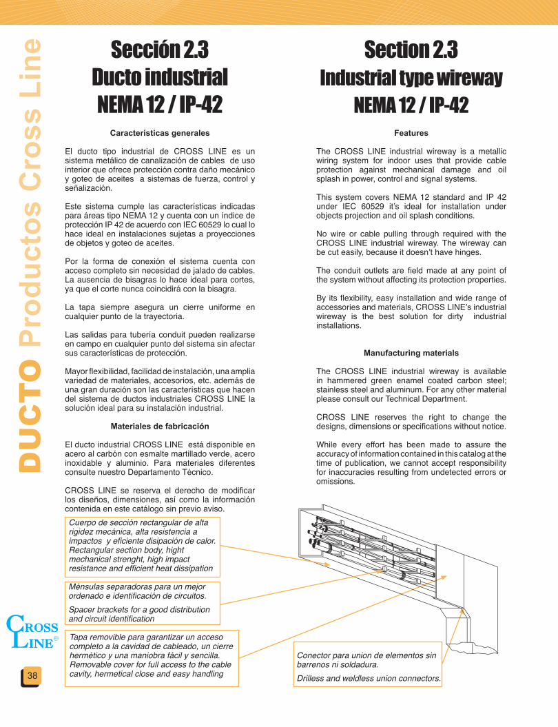
DU
CT
O P
rodu
ctos
Cro
ss L
ine
38
Características generales
El ducto tipo industrial de CROSS LINE es un sistema metálico de canalización de cables de uso interior que ofrece protección contra daño mecánico y goteo de aceites a sistemas de fuerza, control y señalización.
Este sistema cumple las características indicadas para áreas tipo NEMA 12 y cuenta con un índice de protección IP 42 de acuerdo con IEC 60529 lo cual lo hace ideal en instalaciones sujetas a proyecciones de objetos y goteo de aceites.
Por la forma de conexión el sistema cuenta con acceso completo sin necesidad de jalado de cables.La ausencia de bisagras lo hace ideal para cortes, ya que el corte nunca coincidirá con la bisagra.
La tapa siempre asegura un cierre uniforme en cualquier punto de la trayectoria.
Las salidas para tubería conduit pueden realizarse en campo en cualquier punto del sistema sin afectar sus características de protección.
Mayor flexibilidad, facilidad de instalación, una amplia variedad de materiales, accesorios, etc. además de una gran duración son las características que hacen del sistema de ductos industriales CROSS LINE la solución ideal para su instalación industrial.
Materiales de fabricación
El ducto industrial CROSS LINE está disponible en acero al carbón con esmalte martillado verde, acero inoxidable y aluminio. Para materiales diferentes consulte nuestro Departamento Técnico.
CROSS LINE se reserva el derecho de modificar los diseños, dimensiones, así como la información contenida en este catálogo sin previo aviso.
Features
The CROSS LINE industrial wireway is a metallic wiring system for indoor uses that provide cable protection against mechanical damage and oil splash in power, control and signal systems.
This system covers NEMA 12 standard and IP 42 under IEC 60529 it’s ideal for installation under objects projection and oil splash conditions.
No wire or cable pulling through required with the CROSS LINE industrial wireway. The wireway can be cut easily, because it doesn’t have hinges.
The conduit outlets are field made at any point of the system without affecting its protection properties.
By its flexibility, easy installation and wide range of accessories and materials, CROSS LINE’s industrial wireway is the best solution for dirty industrial installations.
Manufacturing materials
The CROSS LINE industrial wireway is available in hammered green enamel coated carbon steel; stainless steel and aluminum. For any other material please consult our Technical Department.
CROSS LINE reserves the right to change the designs, dimensions or specifications without notice.
While every effort has been made to assure the accuracy of information contained in this catalog at the time of publication, we cannot accept responsibility for inaccuracies resulting from undetected errors or omissions.
Sección 2.3 Ducto industrial NEMA 12 / IP-42
Section 2.3 Industrial type wireway
NEMA 12 / IP-42
Cuerpo de sección rectangular de alta rigidez mecánica, alta resistencia a impactos y eficiente disipación de calor.Rectangular section body, hight mechanical strenght, high impact resistance and efficient heat dissipation
Ménsulas separadoras para un mejor ordenado e identificación de circuitos.Spacer brackets for a good distribution and circuit identification
Tapa removible para garantizar un acceso completo a la cavidad de cableado, un cierre hermético y una maniobra fácil y sencilla.Removable cover for full access to the cable cavity, hermetical close and easy handling
Conector para union de elementos sin barrenos ni soldadura.Drilless and weldless union connectors.

39
WIR
EW
AY
Cro
ss L
ine
Pro
duct
sTramo recto • Straight section
Conectores • Connectors
Codo horizontal a 90° • 90° Horizontal elbow
DRAE-150-P
DCGAE-150-GI
DCHAE-15090-GI
Material y acabado • Material & finishesDimensión nominal • Nominal sizeTramo recto • Straight section
Material y acabado • Material & finishesDimensión nominal • Nominal sizeConector • Connector
Material y acabado • Material & finishesÁngulo del codo 90° • Elbow angle 90° Dimensión nominal • Nominal sizeCodo horizontal • Horizontal elbow
Longitudes: 1.51m (60”) y 3.05m (120”)Incluye conector con tornillería y ménsulas • Connector, hardware and brackets included
No. de catálogoCatalog number
Dimensiones • DimensionsA H
DRAE-50 50 (2) 100 (4)DRAE-75 75 (3) 150 (6)
DRAE-100 100 (4) 200 (7.87)DRAE-150 150 (6) 300 (11.81)DRAE-200 200 (7.87) 400 (15.75)
No. de catálogoCatalog number
Dimensiones • DimensionsA H
DCGAE-50 50 (2) 100 (4)DCGAE-75 75 (3) 150 (6)
DCGAE-100 100 (4) 200 (7.87)DCGAE-150 150 (6) 300 (11.81)DCGAE-200 200 (7.87) 400 (15.75)
Materiales y acabados:P: Acero al carbón / Pintura electrostática verde martilladoA: Aluminio acabado naturalAI: Acero inoxidable Todas las dimensiones en mm (pulg)
Materials&finishes:P: Carbon steel / Electrostatic green hamered enamelA: Natural finished aluminumAI: Stainless steel All dimensions are in mm (in)
No. de catálogoCatalog number
Dimensiones• DimensionsA H L
DCHAE-5090 50 (2) 100 (4) 110 (4.33)DCHAE-7590 75 (3) 150 (6) 160 (6.30)
DCHAE-10090 100 (4) 200 (7.87) 210 (8.27)DCHAE-15090 150 (6) 300 (11.81) 280 (11.02)DCHAE-20090 200 (7.87) 400 (15.75) 360 (14.17)
L L
H
A
1524 (60)
250(10)
508(20)
A
H
50 (2)
50 (2)
50 (2)
Incluye tornillería • Hardware included
Incluye conector con tornillería y ménsulas • Connector, hardware and branches inlcuded

DU
CT
O P
rodu
ctos
Cro
ss L
ine
40
Codo horizontal inverso a 90° • 90° Horizontal inverse elbow
Codo horizontal a 45° • 45° Horizontal elbow
Codo horizontal inverso a 45° • 45° Horizontal inverse elbow
Codo vertical a 90° • 90° Vertical elbow
DCIHAE-15090-GI
DCHAE-15045-GI
DCIHAE-15045-GI
DCVAE-15090-GI
No. de catálogoCatalog number
Dimensiones• DimensionsA H L
DCIHAE-5090 50 (2) 100 (4) 110 (4.33)DCIHAE-7590 75 (3) 150 (6) 160 (6.30)
DCIHAE-10090 100 (4) 200 (7.87) 210 (8.27)DCIHAE-15090 150 (6) 300 (11.81) 280 (11.02)DCIHAE-20090 200 (7.87) 400 (15.75) 360 (14.17)
No. de catálogoCatalog number
Dimensiones• DimensionsA H L
DCHAE-5045 50 (2) 100 (4) 100 (4)DCHAE-7545 75 (3) 150 (6) 150 (6)
DCHAE-10045 100 (4) 200 (7.87) 200 (7.8)DCHAE-15045 150 (6) 300 (11.81) 250 (9.8)DCHAE-20045 200 (7.87) 400 (15.75) 300 (11.8)
No. de catálogoCatalog number
Dimensiones• DimensionsA H L
DCIHAE-5045 50 (2) 100 (4) 100 (4)DCIHAE-7545 75 (3) 150 (6) 150 (6)
DCIHAE-10045 100 (4) 200 (7.87) 200 (7.8)DCIHAE-15045 150 (6) 300 (11.81) 250 (9.8)DCIHAE-20045 200 (7.87) 400 (15.75) 300 (11.8)
No. de catálogoCatalog number
Dimensiones• DimensionsA H L
DCVAE-5090 50 (2) 100 (4) 160 (6.3)DCVAE-7590 75 (3) 150 (6) 230 (9)
DCVAE-10090 100 (4) 200 (7.87) 310 (12.2)DCVAE-15090 150 (6) 300 (11.81) 420 (16.5)DCVAE-20090 200 (7.87) 400 (15.75) 560 (22)
H
A
L LMaterial y acabado • Material & finishesÁngulo del codo 90° • Elbow angle 90° Dimensión nominal • Nominal sizeCodo horizontal inverso • Horizontal inverse elbow
Material y acabado • Material & finishesÁngulo del codo 45° • Elbow angle 45° Dimensión nominal • Nominal sizeCodo horizontal • Horizontal elbow
Material y acabado • Material & finishesÁngulo del codo 90° • Elbow angle 90° Dimensión nominal • Nominal sizeCodo vertical • Vertical elbow
H
A
LL
Materiales y acabados:P: Acero al carbón / Pintura electrostática verde martilladoA: Aluminio acabado naturalAI: Acero inoxidable Todas las dimensiones en mm (pulg)
Materials&finishes:P: Carbon steel / Electrostatic green hamered enamelA: Natural finished aluminumAI: Stainless steel All dimensions are in mm (in)
L
L
H
A
L
H
A
Incluye conector con tornillería y ménsulas • Connector, hardware and branches included
Incluye conector con tornillería y ménsulas • Connector, hardware and branches included
Incluye conector con tornillería y ménsulas • Connector, hardware and branches included
Incluye conector con tornillería y ménsulas • Connector hardware and branches included.
Material y acabado • Material & finishesÁngulo del codo 45° • Elbow angle 45° Dimensión nominal • Nominal sizeCodo horizontal inverso • Horizontal inverse elbow

41
WIR
EW
AY
Cro
ss L
ine
Pro
duct
sCodo vertical a 45° • 45° Vertical elbow
Tee horizontal • Horizontal tee
Tee vertical • Vertical tee
DCVAE-15045-GI
DTHAE-150-GI
No. de catálogoCatalog number
Dimensiones• DimensionsA H L
DCVAE-5045 50 (2) 100 (4) 150 (6)DCVAE-7545 75 (3) 150 (6) 230 (7.9)
DCVAE-10045 100 (4) 200 (7.87) 250 (9.8)DCVAE-15045 150 (6) 300 (11.81) 300 (11.8)DCVAE-20045 200 (7.87) 400 (15.75) 400 (15.7)
No. de catálogoCatalog number
Dimensiones• DimensionsA H L L1
DTHAE-50 50 (2) 100 (4) 165 (6.5) 100 (4)DTHAE-75 75 (3) 150 (6) 240 (9.5) 150 (6)
DTHAE-100 100 (4) 200 (7.87) 315(12.4) 200 (7.8)DTHAE-150 150 (6) 300 (11.81) 400 (15.75) 250 (9.8)DTHAE-200 200 (7.87) 400 (15.75) 510 (20) 300 (11.8)
No. de catálogoCatalog number
Dimensiones• DimensionsA H L L1
DTVAE-50 50 (2) 100 (4) 215 (8.5) 170 (6.7)DTVAE-75 75 (3) 150 (6) 315 (12.5) 250 (9.8)
DTVAE-100 100 (4) 200 (7.87) 415 (16.4) 320 (12.6)DTVAE-150 150 (6) 300 (11.81) 550 (21.7) 440 (17.3)DTVAE-200 200 (7.87) 400 (15.75) 710 (27.9) 570 (22.4)
Material y acabado • Material & finishesÁngulo del codo 45° • Elbow angle 45° Dimensión nominal • Nominal sizeCodo vertical • Vertical elbow
Material y acabado • Material & finishesDimensión nominal • Nominal sizeTee horizontal • Horizontal tee
Material y acabado • Material & finishesDimensión nominal • Nominal sizeTee vertical • Vertical tee
Materiales y acabados:P: Acero al carbón / Pintura electrostática verde martilladoA: Aluminio acabado naturalAI: Acero inoxidable Todas las dimensiones en mm (pulg)
Materials&finishes:P: Carbon steel / Electrostatic green hamered enamelA: Natural finished aluminumAI: Stainless steel All dimensions are in mm (in)
H
L
A
LL1
A
A
L
H
L1
H
Incluye conector con tornillería y ménsulas • Connector, hardware and branches included
Incluye conector con tornillería y ménsulas • Connector, hardware and branches included
Incluye conector con tornillería y ménsulas • Connector, hardware and branches included
DTVAE-150-GI
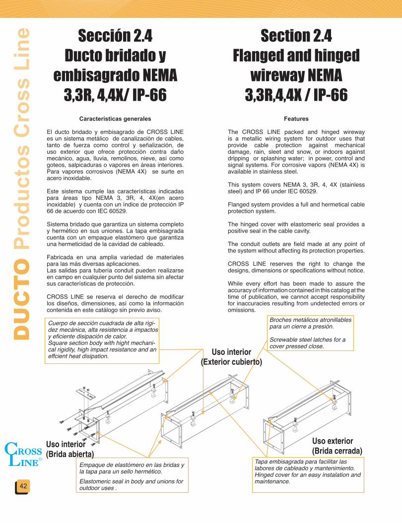
DU
CT
O P
rodu
ctos
Cro
ss L
ine
42
Características generales
El ducto bridado y embisagrado de CROSS LINE es un sistema metálico de canalización de cables, tanto de fuerza como control y señalización, de uso exterior que ofrece protección contra daño mecánico, agua, lluvia, remolinos, nieve, así como goteos, salpicaduras o vapores en áreas interiores. Para vapores corrosivos (NEMA 4X) se surte en acero inoxidable.
Este sistema cumple las características indicadas para áreas tipo NEMA 3, 3R, 4, 4X(en acero inoxidable) y cuenta con un índice de protección IP 66 de acuerdo con IEC 60529.
Sistema bridado que garantiza un sistema completo y hermético en sus uniones. La tapa embisagrada cuenta con un empaque elastómero que garantiza una hermeticidad de la cavidad de cableado.
Fabricada en una amplia variedad de materiales para las más diversas aplicaciones.Las salidas para tubería conduit pueden realizarse en campo en cualquier punto del sistema sin afectar sus características de protección.
CROSS LINE se reserva el derecho de modificar los diseños, dimensiones, así como la información contenida en este catálogo sin previo aviso.
Features
The CROSS LINE packed and hinged wireway is a metallic wiring system for outdoor uses that provide cable protection against mechanical damage, rain, sleet and snow, or indoors against dripping or splashing water; in power, control and signal systems. For corrosive vapors (NEMA 4X) is available in stainless steel.
This system covers NEMA 3, 3R, 4, 4X (stainless steel) and IP 66 under IEC 60529.
Flanged system provides a full and hermetical cable protection system.
The hinged cover with elastomeric seal provides a positive seal in the cable cavity.
The conduit outlets are field made at any point of the system without affecting its protection properties.
CROSS LINE reserves the right to change the designs, dimensions or specifications without notice.
While every effort has been made to assure the accuracy of information contained in this catalog at the time of publication, we cannot accept responsibility for inaccuracies resulting from undetected errors or omissions.
Sección 2.4 Ducto bridado y
embisagrado NEMA 3,3R, 4,4X/ IP-66
Section 2.4 Flanged and hinged
wireway NEMA 3,3R,4,4X / IP-66
Cuerpo de sección cuadrada de alta rigi-dez mecánica, alta resistencia a impactos y eficiente disipación de calor.Square section body with hight mechani-cal rigidity, high impact resistance and an effcient heat disipation.
Empaque de elastómero en las bridas y la tapa para un sello hermético.Elastomeric seal in body and unions for outdoor uses .
Tapa embisagrada para facilitar las labores de cableado y mantenimiento.Hinged cover for an easy instalation and maintenance.
Broches metálicos atronillables para un cierre a presión.
Screwable steel latches for a cover pressed close.
Uso interior(Brida abierta)
Uso exterior(Brida cerrada)
Uso interior(Exterior cubierto)
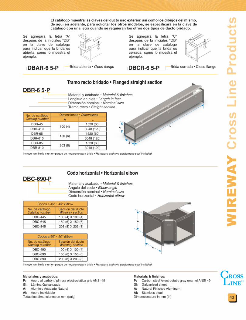
43
WIR
EW
AY
Cro
ss L
ine
Pro
duct
s
A
AL
El catálogo muestra las claves del ducto uso exterior, asi como los dibujos del mismo, de aqui en adelante, para solicitar los otros modelos, se especificara en la clave de catálogo con una letra cuando se requieran los otros dos tipos de ducto bridado.
DBAR-6 5-P DBCR-6 5-P
Se agregara la letra “A” después de la iniciales “DB” en la clave de catálogo para indicar que la brida es abierta, como lo muestra el ejemplo.
Se agregara la letra “C” después de la iniciales “DB” en la clave de catálogo para indicar que la brida es cerrada, como lo muestra el ejemplo.
Brida abierta • Open flange Brida cerrada • Close flange
Tramo recto bridado • Flanged straight section
Codo horizontal • Horizontal elbow
DBR-6 5-PMaterial y acabado • Material & finishesLongitud en pies • Length in feetDimensión nominal • Nominal sizeTramo recto • Staight section
No. de catálogoCatalog number
Dimensiones • DimensionsA L
DBR-45100 (4)
1520 (60)DBR-410 3048 (120)DBR-65
150 (6)1520 (60)
DBR-610 3048 (120)DBR-85
203 (8)1520 (60)
DBR-810 3048 (120)
Codos a 45° • 45° ElbowNo. de catálogoCatalog number
Sección del ductoWireway section
DBC-445 100 (4) X 100 (4)DBC-645 150 (6) X 150 (6)DBC-845 203 (8) X 203 (8)
Codos a 90° • 90° ElbowNo. de catálogoCatalog number
Sección del ductoWireway section
DBC-490 100 (4) X 100 (4)DBC-690 150 (6) X 150 (6)DBC-890 203 (8) X 203 (8)
Material y acabado • Material & finishesÁngulo del codo • Elbow angleDimensión nominal • Nominal sizeCodo horizontal • Horizontal elbow
A
A
Materiales y acabados:P: Acero al carbón / pintura electrostática gris ANSI-49GI: Lámina GalvanizadaA: Aluminio Acabado NaturalAI: Acero inoxidableTodas las dimensiones en mm (pulg)
Materials&finishes:P: Carbon steel /electrostatic gray enamel ANSI 49GI: Galvanized sheetA: Natural Finished AluminumAI: Stainless steelDimensions are in mm (in)
Incluye tornillería y un empaque de neopreno para brida • Hardware and one elastomeric seal included
Incluye tornillería y un empaque de neopreno para brida • Hardware and one elastomeric seal included
DBC-690-P
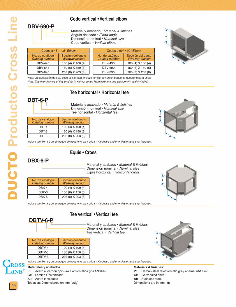
DU
CT
O P
rodu
ctos
Cro
ss L
ine
44
Codo vertical • Vertical elbow
Tee horizontal • Horizontal tee
Equis • Cross
Tee vertical • Vertical tee
DBX-6-P
DBTV-6-P
Codos a 45° • 45° ElbowNo. de catálogoCatalog number
Sección del ductoWireway section
DBV-445 100 (4) X 100 (4)DBV-645 150 (6) X 150 (6)DBV-845 203 (8) X 203 (8)
No. de catálogoCatalog number
Sección del ductoWireway section
DBT-4 100 (4) X 100 (4)DBT-6 150 (6) X 150 (6)DBT-8 203 (8) X 203 (8)
No. de catálogoCatalog number
Sección del ductoWireway section
DBX-4 100 (4) X 100 (4)DBX-6 150 (6) X 150 (6)DBX-8 203 (8) X 203 (8)
No. de catálogoCatalog number
Sección del ductoWireway section
DBTV-4 100 (4) X 100 (4)DBTV-6 150 (6) X 150 (6)DBTV-8 203 (8) X 203 (8)
Codos a 90° • 90° ElbowNo. de catálogoCatalog number
Sección del ductoWireway section
DBV-490 100 (4) X 100 (4)DBV-690 150 (6) X 150 (6)DBV-890 203 (8) X 203 (8)
Material y acabado • Material & finishesÁngulo del codo • Elbow angleDimensión nominal • Nominal sizeCodo vertical • Vertical elbow
Material y acabado • Material & finishesDimensión nominal • Nominal sizeTee horizontal • Horizontal tee
Material y acabado • Material & finishesDimensión nominal • Nominal sizeEquis horizontal • Horizontal cross
Material y acabado • Material & finishesDimensión nominal • Nominal sizeTee vertical • Vertical tee
A
A
A
A
A
A
A
A
Nota: La fabricación de este codo es sin tapa. Incluye tornillería y un empaque de neopreno para brida.Note: The manufacture of this product is without cover. Hardware and one elastomeric seal included.
Materiales y acabados:P: Acero al carbón / pintura electrostática gris ANSI-49GI: Lámina GalvanizadaAI: Acero inoxidableTodas las Dimensiones en mm (pulg)
Materials&finishes:P: Carbon steel /electrostatic gray enamel ANSI 49GI: Galvanized sheetAI: Stainless steelDimensions are in mm (in)
Incluye tornillería y un empaque de neopreno para brida • Hardware and one elastomeric seal included.
Incluye tornillería y un empaque de neopreno para brida • Hardware and one elastomeric seal included.
Incluye tornillería y un empaque de neopreno para brida • Hardware and one elastomeric seal included.
DBV-690-P
DBT-6-P

45
WIR
EW
AY
Cro
ss L
ine
Pro
duct
sReducción • Reducer
Conector de expansión • Expansion connector
Tapa terminal • End blank
DBRR-64-P
DBE-6-P
DBPTR-6-P
No. de catálogoCatalog number
Sección mayorLargest section
Sección menorSmallest section
DBRR-86 203 (8) X 203 (8) 150 (6) X 150 (6)DBRR-84 203 (8) X 203 (8) 100 (4) X 100 (4)DBRR-64 150 (6) X 150 (6) 100 (4) X 100 (4)
No. de catálogoCatalog number
Sección del ductoWireway section
DBE-4 100 (4) X 100 (4)DBE-6 150 (6) X 150 (6)DBE-8 203 (8) X 203 (8)
No. de catálogoCatalog number
Sección del ductoWireway section
DBPTR-4 100 (4) X 100 (4)DBPTR-6 150 (6) X 150 (6)DBPTR-8 203 (8) X 203 (8)
Material y acabado • Material & finishesDimensión nominal menor • Smaller nominal sizeDimensión nominal mayor • Larger nominal sizeReducción • Reducer
Material y acabado • Material & finishesDimensión nominal • Nominal sizeConector de expansión • Expansion connector
Material y acabado • Material & finishesDimensión nominal • Nominal sizeTapa terminal • End blank
Materiales y acabados:P: Acero al carbón / pintura electrostática gris ANSI-49GI: Lámina GalvanizadaAI: Acero inoxidableTodas las Dimensiones en mm (pulg)
Materials&finishes:P: Carbon steel /electrostatic gray enamel ANSI 49GI: Galvanized sheetAI: Stainless steelDimensions are in mm (in)
Incluye tornillería y un empaque de neopreno para bridaHardware and one elastomeric seal included.
Incluye tornillería y un empaque de neopreno para bridaHardware and one elastomeric seal included.
Incluye tornillería y un empaque de neopreno para bridaHardware and one elastomeric seal included.
Colgador • HanderDHBR-6-P
No. de catálogoCatalog number
Sección del ductoWireway section
DHBR-4 100 (4) X 100 (4)DHBR-6 150 (6) X 150 (6)DHBR-8 203 (8) X 203 (8)
Material y acabado • Material & finishesDimensión nominal • Nominal sizeColgador para ducto DBR • DBR wireway hanger
No incluye tornilleríaHardware not included.
Ménsula para pared • Wall BracketDBM-6-P
No. de catálogoCatalog number
Sección del ductoWireway section
DBM-4 100 (4) X 100 (4)DBM-6 150 (6) X 150 (6)DBM-8 203 (8) X 203 (8)
Material y acabado • Material & finishesDimensión nominal • Nominal sizeColgador para ducto DBR • DBR wireway hanger
No incluye tornilleríaHardware not included.
150 a 300(6 a 12)
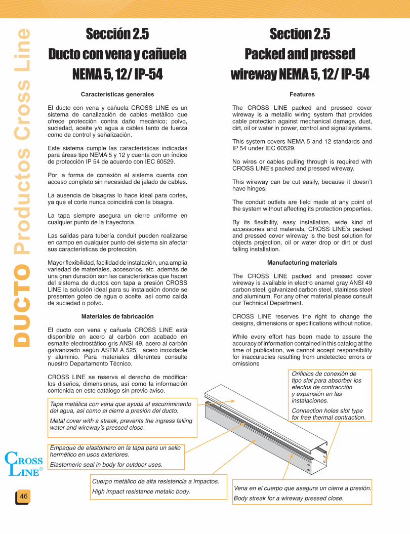
DU
CT
O P
rodu
ctos
Cro
ss L
ine
46
Características generales
El ducto con vena y cañuela CROSS LINE es un sistema de canalización de cables metálico que ofrece protección contra daño mecánico; polvo, suciedad, aceite y/o agua a cables tanto de fuerza como de control y señalización.
Este sistema cumple las características indicadas para áreas tipo NEMA 5 y 12 y cuenta con un índice de protección IP 54 de acuerdo con IEC 60529.
Por la forma de conexión el sistema cuenta con acceso completo sin necesidad de jalado de cables.
La ausencia de bisagras lo hace ideal para cortes, ya que el corte nunca coincidirá con la bisagra.
La tapa siempre asegura un cierre uniforme en cualquier punto de la trayectoria.
Las salidas para tubería conduit pueden realizarse en campo en cualquier punto del sistema sin afectar sus características de protección.
Mayor flexibilidad, facilidad de instalación, una amplia variedad de materiales, accesorios, etc. además de una gran duración son las características que hacen del sistema de ductos con tapa a presión CROSS LINE la solución ideal para su instalación donde se presenten goteo de agua o aceite, así como caída de suciedad o polvo.
Materiales de fabricación
El ducto con vena y cañuela CROSS LINE está disponible en acero al carbón con acabado en esmalte electrostático gris ANSI 49, acero al carbón galvanizado según ASTM A 525, acero inoxidable y aluminio. Para materiales diferentes consulte nuestro Departamento Técnico.
CROSS LINE se reserva el derecho de modificar los diseños, dimensiones, así como la información contenida en este catálogo sin previo aviso.
Features
The CROSS LINE packed and pressed cover wireway is a metallic wiring system that provides cable protection against mechanical damage, dust, dirt, oil or water in power, control and signal systems.
This system covers NEMA 5 and 12 standards and IP 54 under IEC 60529.
No wires or cables pulling through is required with CROSS LINE’s packed and pressed wireway.
This wireway can be cut easily, because it doesn’t have hinges.
The conduit outlets are field made at any point of the system without affecting its protection properties.
By its flexibility, easy installation, wide kind of accessories and materials, CROSS LINE’s packed and pressed cover wireway is the best solution for objects projection, oil or water drop or dirt or dust falling installation.
Manufacturing materials
The CROSS LINE packed and pressed cover wireway is available in electro enamel gray ANSI 49 carbon steel, galvanized carbon steel, stainless steel and aluminum. For any other material please consult our Technical Department.
CROSS LINE reserves the right to change the designs, dimensions or specifications without notice.
While every effort has been made to assure the accuracy of information contained in this catalog at the time of publication, we cannot accept responsibility for inaccuracies resulting from undetected errors or omissions
Sección 2.5Ducto con vena y cañuela
NEMA 5, 12/ IP-54
Section 2.5Packed and pressed
wireway NEMA 5, 12/ IP-54
Tapa metálica con vena que ayuda al escurriminento del agua, asi como al cierre a presión del ducto.Metal cover with a streak, prevents the ingress falling water and wireway’s pressed close.
Empaque de elastómero en la tapa para un sello hermético en usos exteriores.Elastomeric seal in body for outdoor uses.
Cuerpo metálico de alta resistencia a impactos.High impact resistance metalic body. Vena en el cuerpo que asegura un cierre a presión.
Body streak for a wireway pressed close.
Orificios de conexión de tipo slot para absorber los efectos de contracción y expansión en las instalaciones.Connection holes slot type for free thermal contraction.
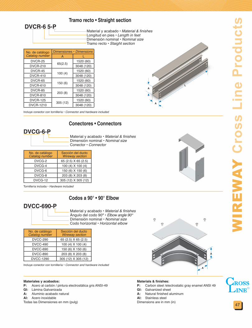
47
WIR
EW
AY
Cro
ss L
ine
Pro
duct
sTramo recto • Straight section
Conectores • Connectors
Codos a 90° • 90° Elbow
DVCR-6 5-PMaterial y acabado • Material & finishesLongitud en pies • Length in feetDimensión nominal • Nominal sizeTramo recto • Staight section
Material y acabado • Material & finishesDimensión nominal • Nominal sizeConector • Connector
Material y acabado • Material & finishesÁngulo del codo 90º • Elbow angle 90°Dimensión nominal • Nominal sizeCodo horizontal • Horizontal elbow
No. de catálogoCatalog number
Dimensiones • DimensionsA L
DVCR-2565(2.5)
1520 (60)DVCR-210 3048 (120)DVCR-45
100 (4)1520 (60)
DVCR-410 3048 (120)DVCR-65
150 (6)1520 (60)
DVCR-610 3048 (120)DVCR-85
203 (8)1520 (60)
DVCR-810 3048 (120)DVCR-125
305 (12)1520 (60)
DVCR-1210 3048 (120) A
LA
Incluye conector con tornillería • Connector and hardware included
Incluye conector con tornillería • Connector and hardware included
Tornillería incluida • Hardware included
No. de catálogoCatalog number
Sección del ductoWireway section
DVCG-2 65 (2.5) X 65 (2.5)DVCG-4 100 (4) X 100 (4)DVCG-6 150 (6) X 150 (6)DVCG-8 203 (8) X 203 (8)
DVCG-12 305 (12) X 305 (12)
No. de catálogoCatalog number
Sección del ductoWireway section
DVCC-290 65 (2.5) X 65 (2.5)DVCC-490 100 (4) X 100 (4)DVCC-690 150 (6) X 150 (6)DVCC-890 203 (8) X 203 (8)
DVCC-1290 305 (12) X 305 (12)
Materiales y acabados:P: Acero al carbón / pintura electrostática gris ANSI-49GI: Lámina GalvanizadaA: Aluminio acabado naturalAI: Acero inoxidableTodas las Dimensiones en mm (pulg)
Materials&finishes:P: Carbon steel /electrostatic gray enamel ANSI 49GI: Galvanized sheetA: Natural finished aluminumAI: Stainless steelDimensions are in mm (in)
A
A
DVCG-6-P
DVCC-690-P
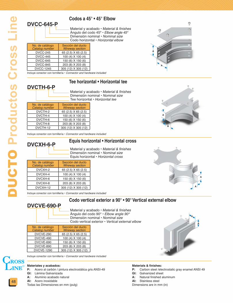
DU
CT
O P
rodu
ctos
Cro
ss L
ine
48
Codos a 45° • 45° Elbow
Tee horizontal • Horizontal tee
Equis horizontal • Horizontal cross
Codo vertical exterior a 90° • 90° Vertical external elbow
DVCTH-6-P
DVCXH-6-P
DVCVE-690-P
Material y acabado • Material & finishesÁngulo del codo 45º • Elbow angle 45°Dimensión nominal • Nominal sizeCodo horizontal • Horizontal elbow
Material y acabado • Material & finishesDimensión nominal • Nominal sizeTee horizontal • Horizontal tee
Material y acabado • Material & finishesDimensión nominal • Nominal sizeEquis horizontal • Horizontal cross
Material y acabado • Material & finishesÁngulo del codo 90° • Elbow angle 90°Dimensión nominal • Nominal sizeCodo vertical exterior • Vertical external elbow
Incluye conector con tornillería • Connector and hardware included
Incluye conector con tornillería • Connector and hardware included
Incluye conector con tornillería • Connector and hardware included
Incluye conector con tornillería • Connector and hardware included
No. de catálogoCatalog number
Sección del ductoWireway section
DVCC-245 65 (2.5) X 65 (2.5)DVCC-445 100 (4) X 100 (4)DVCC-645 150 (6) X 150 (6)DVCC-845 203 (8) X 203 (8)
DVCC-1245 305 (12) X 305 (12)
No. de catálogoCatalog number
Sección del ductoWireway section
DVCTH-2 65 (2.5) X 65 (2.5)DVCTH-4 100 (4) X 100 (4)DVCTH-6 150 (6) X 150 (6)DVCTH-8 203 (8) X 203 (8)
DVCTH-12 305 (12) X 305 (12)
No. de catálogoCatalog number
Sección del ductoWireway section
DVCXH-2 65 (2.5) X 65 (2.5)DVCXH-4 100 (4) X 100 (4)DVCXH-6 150 (6) X 150 (6)DVCXH-8 203 (8) X 203 (8)
DVCXH-12 305 (12) X 305 (12)
No. de catálogoCatalog number
Sección del ductoWireway section
DVCVE-290 65 (2.5) X 65 (2.5)DVCVE-490 100 (4) X 100 (4)DVCVE-690 150 (6) X 150 (6)DVCVE-890 203 (8) X 203 (8)
DVCVE-1290 305 (12) X 305 (12)
Materiales y acabados:P: Acero al carbón / pintura electrostática gris ANSI-49GI: Lámina GalvanizadaA: Aluminio acabado naturalAI: Acero inoxidableTodas las Dimensiones en mm (pulg)
Materials&finishes:P: Carbon steel /electrostatic gray enamel ANSI 49GI: Galvanized sheetA: Natural finished aluminumAI: Stainless steelDimensions are in mm (in)
A
A
A
A
A
A
A
A
DVCC-645-P

49
WIR
EW
AY
Cro
ss L
ine
Pro
duct
sCodo vertical exterior a 45° • 45° Vertical external elbow
Codo vertical interior a 45° • 45° Vertical internal elbow
Tee vertical • Vertical tee
DVCVE-645-P
DVCVI-690-P
DVCVI-645-P
DVCTV-690-P
Material y acabado • Material & finishesÁngulo del codo 90° • Elbow angle 90°Dimensión nominal • Nominal sizeCodo vertical interior • Vertical internal elbow
Material y acabado • Material & finishesÁngulo del codo 90° • Elbow angle 90°Dimensión nominal • Nominal sizeTee vertical • Vertical tee
Incluye conector con tornillería • Connector and hardware included
Incluye conector con tornillería • Connector and hardware included
Incluye conector con tornillería • Connector and hardware included
Incluye conector con tornillería • Connector and hardware included
No. de catálogoCatalog number
Sección del ductoWireway section
DVCVE-245 65 (2.5) X 65 (2.5)DVCVE-445 100 (4) X 100 (4)DVCVE-645 150 (6) X 150 (6)DVCVE-845 203 (8) X 203 (8)
DVCVE-1245 305 (12) X 305 (12)
No. de catálogoCatalog number
Sección del ductoWireway section
DVCVI-290 65 (2.5) X 65 (2.5)DVCVI-490 100 (4) X 100 (4)DVCVI-690 150 (6) X 150 (6)DVCVI-890 203 (8) X 203 (8)
DVCVI-1290 305 (12) X 305 (12)
No. de catálogoCatalog number
Sección del ductoWireway section
DVCVI-245 65 (2.5) X 65 (2.5)DVCVI-445 100 (4) X 100 (4)DVCVI-645 150 (6) X 150 (6)DVCVI-845 203 (8) X 203 (8)
DVCVI-1245 305 (12) X 305 (12)
No. de catálogoCatalog number
Sección del ductoWireway section
DVCTV-2 65 (2.5) X 65 (2.5)DVCTV-4 100 (4) X 100 (4)DVCTV-6 150 (6) X 150 (6)DVCTV-8 203 (8) X 203 (8)
DVCTV-12 305 (12) X 305 (12)
Materiales y acabados:P: Acero al carbón / pintura electrostática gris ANSI-49GI: Lámina GalvanizadaA: Aluminio acabado naturalAI: Acero inoxidableTodas las Dimensiones en mm (pulg)
Materials&finishes:P: Carbon steel /electrostatic gray enamel ANSI 49GI: Galvanized sheetA: Natural finished aluminumAI: Stainless steelDimensions are in mm (in)
A
A
A
A
A
A
Material y acabado • Material & finishesÁngulo del codo 45º • Elbow angle 45°Dimensión nominal • Nominal sizeCodo vertical exterior • Vertical external elbow
Codo vertical interior a 90° • 90° Vertical internal elbow
AA
Material y acabado • Material & finishesÁngulo del codo 45° • Elbow angle 45°Dimensión nominal • Nominal sizeCodo vertical interior • Vertical internal elbow

AB
RA
ZA
DE
RA
S P
rodu
ctos
Cro
ss L
ine
50
Abrazadera tipo columpio servicio pesado y ligero
Heavy & light duty clevis hanger
Tornillo y tuerca de unión incluidosUnion nut and screw included
Sección 3 Abrazaderas para
tubería
Section 3Pipe clamps
No. de catálogoCatalog number
Diámetro nominalConduit size
Diámetro de varillaRod size
ACO65-38 3/8 9.5 (3/8)ACO65-12 1/2 9.5 (3/8)ACO65-34 3/4 9.5 (3/8)ACO65-1 1 9.5 (3/8)
ACO65-114 1 1/4 9.5 (3/8)ACO65-112 1 1/2 9.5 (3/8)ACO65-2 2 9.5 (3/8)
ACO65-212 2 1/2 12.7 (½)ACO65-3 3 12.7 (½)
ACO65-312 3 1/2 12.7 (½)ACO65-4 4 12.7 (½)
ACO260-5 5 15.8 (5/8)ACO260-6 6 19 (3/4)ACO260-8 8 19 (3/4)
ACO260-10 10 22.2 (7/8)ACO260-12 12 22.2 (7/8)ACO260-14 14 25.4 (1)ACO260-16 16 25.4 (1)ACO260-18 18 25.4 (1)ACO260-20 20 31.8 (1 1/4)ACO260-24 24 31.8 (1 1/4)ACO260-30 30 31.8 (1 1/4)ACO260-36 36 38.1 (1 ½)
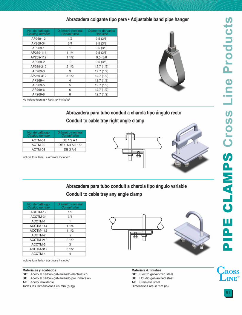
51
PIP
E C
LA
MP
S C
ross
Lin
e P
rodu
ctsAbrazadera colgante tipo pera • Adjustable band pipe hanger
Abrazadera para tubo conduit a charola tipo ángulo recto
Conduit to cable tray right angle clamp
Abrazadera para tubo conduit a charola tipo ángulo variable
Conduit to cable tray any angle clamp
No. de catálogoCatalog number
Diámetro nominalConduit size
Diámetro de varillaRod size
AP269-12 1/2 9.5 (3/8)AP269-34 3/4 9.5 (3/8)AP269-1 1 9.5 (3/8)
AP269-114 1 1/4 9.5 (3/8)AP269-112 1 1/2 9.5 (3/8AP269-2 2 9.5 (3/8)
AP269-212 2 1/2 12.7 (1/2)AP269-3 3 12.7 (1/2)
AP269-312 3 1/2 12.7 (1/2)AP269-4 4 12.7 (1/2)AP269-5 5 12.7 (1/2)AP269-6 6 12.7 (1/2)AP269-8 8 12.7 (1/2)
No. de catálogoCatalog number
Diámetro nominalConduit size
ACTM-01 DE 1/2 A 1ACTM-02 DE 1 1/4 A 2 1/2ACTM-03 DE 3 A 6
No. de catálogoCatalog number
Diámetro nominalConduit size
ACCTM-12 1/2 ACCTM-34 3/4ACCTM-1 1
ACCTM-114 1 1/4ACCTM-112 1 1/2ACCTM-2 2
ACCTM-212 2 1/2ACCTM-3 3
ACCTM-312 3 1/2ACCTM-4 4
No incluye tuercas • Nuts not included
Incluye tornillería • Hardware included
Incluye tornillería • Hardware included
Materiales y acabados:GE: Acero al carbón galvanizado electrolíticoGI: Acero al carbón galvanizado por inmersiónAI: Acero inoxidableTodas las Dimensiones en mm (pulg)
Materials&finishes:GE: Electro galvanized steelGI: Hot dip galvanized steetAI: Stainless steelDimensions are in mm (in)

AB
RA
ZA
DE
RA
S P
rodu
ctos
Cro
ss L
ine
52
Abrazadera tipo “U” servicio ligero • Light duty U-bolt
Abrazadera tipo “U” servicio pesado • Heavy duty U-bolt
Abrazadera tipo “U” con mordaza • Beam U-bolt clamp
No. de catálogoCatalog number
Diámetro nominalConduit size
Diámetro de varillaRod size
AU120-1/2 1/2 6.3 (1/4)AU120-3/4 3/4 6.3 (1/4)AU120-1 1 6.3 (1/4)
AU120-1 1/4 1 1/4 6.3 (1/4)AU120-1 1/2 1 1/2 6.3 (1/4)
AU120-2 2 6.3 (1/4)AU120-2 1/2 2 1/2 9.5 (3/8)
AU120-3 3 9.5 (3/8)AU120-3 1/2 3 1/2 9.5 (3/8)
AU120-4 4 9.5 (3/8)AU120-5 5 9.5 (3/8)AU120-6 6 12.7 (1/2)AU120-8 8 12.7 (1/2)
AU120-10 10 15.8 (5/8)
No. de catálogoCatalog number
Diámetro nominalConduit size
Diámetro de varillaRod size
AU137-1 1/4 1 1/4 9.5 (3/8)AU137-1 1/2 1 1/2 9.5 (3/8)
AU137-2 2 9.5 (3/8)AU137-2 1/2 2 1/2 12.7 (1/2)
AU137-3 3 12.7 (1/2)AU137-3 1/2 3 1/2 12.7 (1/2)
AU137-4 4 12.7 (1/2)AU137-5 5 12.7 (1/2)AU137-6 6 15.8 (5/8)AU137-8 8 15.8 (5/8)
AU137-10 10 19 (3/4)AU137-12 12 22.2 (7/8)AU137-14 14 22.2 (7/8)AU137-16 16 22.2 (7/8)AU137-18 18 25.4 (1)AU137-20 20 25.4 (1)
No. de catálogoCatalog number
Diámetro nominalConduit size
Diámetro de varillaRod size
AU M3012 1/2 6.3 (1/4)AU M3034 3/4 6.3 (1/4)AU M301 1 6.3 (1/4)
AU M30114 1 1/4 6.3 (1/4)AU M30112 1 1/2 9.5 (3/8)AU M302 2 9.5 (3/8)
AU M30212 2 1/2 12.7 (1/2)AU M303 3 12.7 (1/2)
AU M30312 3 1/2 12.7 (1/2)AU M304 4 12.7 (1/2)
No incluye tuercas • Nuts not included
Incluye 4 tuercas • Four nuts included
Incluye 2 tuercas • Two nuts included
Materiales y acabados:GE: Acero al carbón galvanizado electrolíticoGI: Acero al carbón galvanizado por inmersiónAI: Acero inoxidableTodas las Dimensiones en mm (pulg)
Materials&finishes:GE: Electro galvanized steelGI: Hot dip galvanized sheetAI: Stainless steelDimensions are in mm (in)
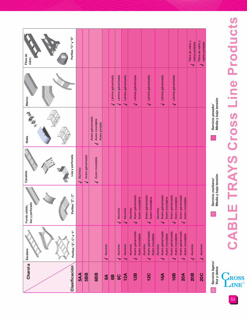
53
CA
BLE
TR
AYS
Cro
ss L
ine
Pro
duct
s
Cha
rola
Esc
aler
aF
ond
o s
ólid
o,
liso
y p
erfo
rad
o
Can
alet
a
Lisa
y p
erfo
rad
a
Mal
laM
arin
oF
ibra
de
vid
rio
5AA
√A
lum
inio
5BB
√A
cero
gal
vani
zad
o
6BB
√A
cero
inox
idab
le√
Ace
ro g
alva
niza
do
Ace
ro in
oxid
able
Ace
ro p
inta
do
8A√
Alu
min
io
8B√
Lám
ina
galv
aniz
ada
8C√
Alu
min
io√
Alu
min
io√
Lám
ina
galv
aniz
ada
12A
√A
lum
inio
√A
lum
inio
√Lá
min
a ga
lvan
izad
a
12B
√A
lum
inio
Ace
ro g
alva
niza
do
Ace
ro in
oxid
able
√A
lum
inio
Ace
ro g
alva
niza
do
Ace
ro in
oxid
able
√Lá
min
a ga
lvan
izad
a
12C
√A
lum
inio
Ace
ro g
alva
niza
do
Ace
ro in
oxid
able
√A
cero
gal
vani
zad
o
Ace
ro in
oxid
able
√Lá
min
a ga
lvan
izad
a
16A
√A
lum
inio
Ace
ro g
alva
niza
do
Ace
ro in
oxid
able
√A
lum
inio
Ace
ro g
alva
niza
do
Ace
ro in
oxid
able
√Lá
min
a ga
lvan
izad
a
16B
√A
cero
gal
vani
zado
Ace
ro in
oxid
able
√A
cero
gal
vani
zado
Ace
ro in
oxid
able
√
20A
√A
cero
gal
vani
zado
Ace
ro in
oxid
able
√A
cero
gal
vani
zado
Ace
ro in
oxid
able
20B
√A
lum
inio
√Fi
bra
de
vid
rio y
resi
na p
olié
ster
20C
√A
lum
inio
√Fi
bra
de
vid
rio y
resi
na p
olié
ster
Ser
vici
o li
ger
o/
Voz
y d
ato
sS
ervi
cio
med
iano
/ M
edia
y b
aja
tens
ión
Ser
vici
o p
esad
o/
Med
ia y
baj
a te
nsió
nLám
ina
galv
aniz
ada
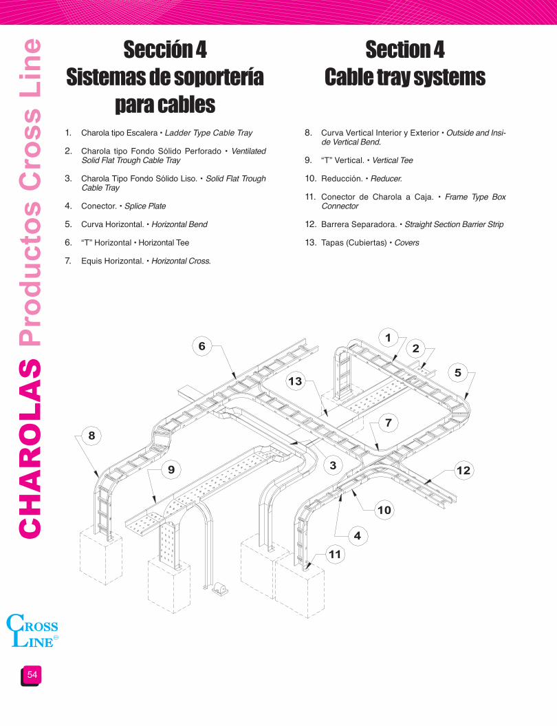
CH
AR
OLA
S P
rodu
ctos
Cro
ss L
ine
54
1. Charola tipo Escalera • Ladder Type Cable Tray
2. Charola tipo Fondo Sólido Perforado • Ventilated Solid Flat Trough Cable Tray
3. Charola Tipo Fondo Sólido Liso. • Solid Flat Trough Cable Tray
4. Conector. • Splice Plate
5. Curva Horizontal. • Horizontal Bend
6. “T” Horizontal • Horizontal Tee
7. Equis Horizontal. • Horizontal Cross.
8. Curva Vertical Interior y Exterior • Outside and Insi-de Vertical Bend.
9. “T” Vertical. • Vertical Tee
10. Reducción. • Reducer.
11. Conector de Charola a Caja. • Frame Type Box Connector
12. Barrera Separadora. • Straight Section Barrier Strip
13. Tapas (Cubiertas) • Covers
Sección 4 Sistemas de soportería
para cables
Section 4 Cable tray systems

55
CA
BLE
TR
AYS
Cro
ss L
ine
Pro
duct
sCertificaciones
CERTIFICADO
DE CONFORMIDAD
DE PRODUCTO
Certificado No.:201001C08148
Este Certificado sustituye al Certificado número: 200901C09542
Página 1 de 2
La Asociación de Normalización y Certificación, A.C., en su cáracter de organismo de Certificación de Producto acreditado y
aprobado en los términos de la Ley Federal sobre Metrología y Normalización (LFMN), de conformidad con los artículos 1, 2, 3
fracciones III, IV-A, XII, XV-A, 38 fracción VI, 52, 53, 68, 70, 70-C, 73, 74, 79, 80, y demás relativos y aplicables de la misma
Ley, así como de su respectivo reglamento, con número de Acreditación 01/10 vigente a partir del 09/03/2010, en atención a la
solicitud con número de Referencia 2007ART00294A/3 de acuerdo al procedimiento de Certificación PROPARCER-10 de
ANCE, otorga el presente Certificado de Conformidad de Producto a:
Titular: CORPORACIÓN MANDRINKA, S.A. DE C.V.
Nombre genérico : SOPORTE PARA CABLES TIPO CHAROLA
MALLA
NINGUNO
Tipo(s):
Subtipo(s):
Marca(s): CROSS LINE
Categoría: NUEVO
Modalidad: PROCEDIMIENTO ANCE
Fabricado y/o importado por: CORPORACIÓN MANDRINKA, S.A. DE C.V.
Bodega : ALESSANDRO VOLTA No. 1 Y 2 INT. S/N COL. PARQUE IND. CUAMATLA DEL. CUAUTITLÁN
IZCALLI C.P. 54730 EDO. DE MÉXICO
Fábrica: ALESSANDRO VOLTA No. 1 Y 2 INT. S/N COL. PARQUE IND. CUAMATLA DEL. CUAUTITLÁN
IZCALLI C.P. 54730 EDO. DE MÉXICO
País(es) de origen: MEXICO
Modelo(s): CL-CL CL (SEGUIDO O NO: -CL)
Especificaciones: Clasificación: 6 BB Ancho: 600 mm Largo: 3 m Malla: 100 mm x 50 mm
Material: Acero Inoxidable
FORCER-P03.07.10
CERTIFICADO
DE CONFORMIDAD
DE PRODUCTO
Certificado No.:201001C08168
Este Certificado sustituye al Certificado número: 200901C09521
Página 1 de 2
La Asociación de Normalización y Certificación, A.C., en su cáracter de organismo de Certificación de Producto acreditado y
aprobado en los términos de la Ley Federal sobre Metrología y Normalización (LFMN), de conformidad con los artículos 1, 2, 3
fracciones III, IV-A, XII, XV-A, 38 fracción VI, 52, 53, 68, 70, 70-C, 73, 74, 79, 80, y demás relativos y aplicables de la misma
Ley, así como de su respectivo reglamento, con número de Acreditación 01/10 vigente a partir del 09/03/2010, en atención a la
solicitud con número de Referencia 2007ART00287A/3 de acuerdo al procedimiento de Certificación PROPARCER-10 de
ANCE, otorga el presente Certificado de Conformidad de Producto a:
Titular: CORPORACIÓN MANDRINKA, S.A. DE C.V.
Nombre genérico : SOPORTE METÁLICO PARA CABLES
MALLA
CHAROLA
Tipo(s):
Subtipo(s):
Marca(s): CROSS LINE
Categoría: NUEVO
Modalidad: PROCEDIMIENTO ANCE
Fabricado y/o importado por: CORPORACIÓN MANDRINKA, S.A. DE C.V.
Bodega : ALESSANDRO VOLTA No. 1 Y 2 INT. S/N COL. PARQUE IND. CUAMATLA DEL. CUAUTITLÁN
IZCALLI C.P. 54730 EDO. DE MÉXICO
Fábrica: ALESSANDRO VOLTA No. 1 Y 2 INT. S/N COL. PARQUE IND. CUAMATLA DEL. CUAUTITLÁN
IZCALLI C.P. 54730 EDO. DE MÉXICO
País(es) de origen: MEXICO
Modelo(s): CL (Seguido o no: -CL)
Especificaciones: MATERIAL: ACERO GALVANIZADO ELECTROLÍTICO
ESPACIAMIENTO ENTRE APOYOS: 1,80 m
DIMENSIONES: LARGO: 3 000 mm ANCHO: 300 mm
CLASIFICACIÓN: 6BB
FORCER-P03.07.10
CH
AR
OLA
S P
rodu
ctos
Cro
ss L
ine
56
Se considera un sistema de soportería tipo charola para cable a una estructura rígida y continua especialmente construida para soportar cables, tubos u otras canalizaciones, las cuales pueden ser de metal u otros materiales no combustibles.
Las charolas para cables CROSS LINE pueden usarse para soportar cables de fuerza, alumbrado, control y señalización que cuenten con aislamiento y cubierta apropiados para este tipo de instalación.
Las charolas CROSS LINE se encuentran disponibles en materiales y acabados adecuados para su instalación a la intemperie o en condiciones ambientales desfavorables.
No se permite su instalación en cubos de ascensores o en aquellos lugares donde estén expuestos a daños mecánicos severos o en áreas clasificadas de acuerdo a los artículos del 500 al 505 de la norma NOM-001 SEDE 2012, a menos que los cables estén aprobados para tal uso.
Las charolas para cables de CROSS LINE cuentan con la suficiente rigidez y resistencia mecánica para proporcionar un soporte adecuado a todo el cableado tendido dentro de ellas.
CROSS LINE cuenta con una amplia gama de charolas metálicas protegidas contra la corrosión, así como no metálicas e incluyen todos los accesorios necesarios para realizar cambios de dirección o de nivel requeridos durante la instalación.
Todas las labores de diseño y fabricación de las charolas CROSS LINE se realizan apegados a las normas tanto nacionales (NMX-J511-ANCE-2011, NOM-001 SEDE 2012) como internacionales (NEMA VE 1-2002, Nacional Electrical Code NEC).
De esta manera el cálculo de las características de un sistema de soportería , tal como ancho, alturas, radios, distancia entre travesaños, etc. Deberá apegarse al artículo 318 de la norma NOM-001 SEDE 2012 o su similar en el código NEC.
El propósito de este catálogo de soportería para cables es el de ayudar a Ingenieros, Proyectistas y Compradores en la selección del material idóneo que cumpla con las características obtenidas en los cálculos indicados en las normas.
Debido a nuestra política de mejora continua de nuestros productos, las especificaciones, dimensiones, así como toda información contenida en este catálogo podrá ser modificada sin previo aviso.
Estamos seguros de que las ventajas que usted encontrará en nuestro sistema de soportería para cables, le convencerán de que:
¡¡¡EN CHAROLAS SEGUIMOS SIENDO LA MEJOR OPCIÓN!!!
A cable tray system is considered as a rigid and continuous metallic structure or other type of non-flammable materials which are built specially to support cable, pipes or others types of electrical channels.
CROSS LINE cable trays can be used as support of different cable type such as power, lighting systems, control or data signals. The cable must have the proper insulation according to the installation type.
CROSS LINE cable trays are available in materials and finishes for outdoors or hostile environment conditions.
Cable tray systems can´t be installed in elevators shafts or areas exposed to mechanical damage.
Cable tray systems can´t be installed in hazardous locations as indicated in articles 500 to 505 of the NEC code unless use a cable approved for this areas.
CROSS LINE cable tray systems are rigid and high mechanical resistance for a proper support of all cables contained inside.
CROSS LINE offers a wide range of cable trays like corrosion resistance metallic systems and non-metallic system, both have the necessary fitting for direction and level changes to offer a complete installation service.
The entire CROSS LINE cable tray’s manufacturing processes, from design to finish are under Mexican (NMX-J511-ANCE-2011, NOM-001 SEDE 2012) as International (NEMA VE 1-2002, National Electrical Code NEC) standards.
So the calculation of cable tray parameters such as width, height, radius, distance between rungs and others, should be according to 318 article of NEC code or NOM-001 SEDE 2012 in Mexico.
This cable tray systems catalog is designed to help general engineers, project engineers and customers for a right cable tray selection, to fulfill the requirements obtained of the standard calculations.
CROSS LINE have a “continuous best product” policy, so the dimensions, specifications and all technical information showed in this catalog can change without notice.
While every effort has been made to assure the accuracy of information contained in this catalog at the time of publication, we cannot accept responsibility for inaccuracies resulting from undetected errors or omissions.
We are sure that the advantages of our cable tray system will convince you that:
IN CABLE TRAY SYSTEMS CROSS LINE IS YOUR BEST CHOICE!!!

57
CA
BLE
TR
AYS
Cro
ss L
ine
Pro
duct
sCargas soportadas
Los sistemas de soportería para cables CROSS LINE al ser diseñados y fabricados bajo la normativa nacional e internacional cumplen con las características de carga indicadas en dichas normas.
Para tal efecto en las siguientes páginas del catálogo se indicará la clasificación requerida por la norma NMX-J-511-ANCE-2011.
Esta norma indica que las cargas soportadas por los sistemas de soportería para cables (de manera principal los tramos rectos) deberán ser declaradas por el fabricante y/o vendedor.
Tomando en cuenta las pruebas declaradas en la norma. La cargas de trabajo admisibles (CTA) están dadas en función del sistema de apoyo, de donde: un sistema continuo de 2 o más charolas son probadas, colocando una carga uniforme a todo lo largo de la charola.
En lo correspondiente a las pruebas de carga admitidas por la norma, la prueba tipo VI da por valido que el fabricante pueda recomendar al instalador la longitud máxima entre apoyos, garantizando así el trabajo mecánico del soporte para cable.
Asimismo la posición de las uniones con respecto al soporte es un factor que el vendedor podrá recomendar al instalador cuando sea un caso desfavorable en la obra.
La carga de seguridad del sistema es la carga destructiva dividida entre un factor de seguridad mínimo de 1.5.
Opcionalmente podrá aplicarse una carga concentrada al centro de la distancia entre apoyos, la magnitud de esta carga deberá ser determinada por el cliente e informada a CROSS LINE para realizar los estudios de factibilidad correspondientes.
Load capacity
CROSS LINE cable tray systems are designed following the standard concepts, covering the required characteristics in load capacity.
In the catalog’s following pages the classification required for the standard NMX-J-511-ANCE-2011 is shown.
This standard indicates that the system supported load (straight sections mainly) will be declared by the manufacturer and/or salesman.
Taking into account the tests declared in the norm. The acceptable workloads (CTA) are given in function of the supporting system, where: a continuous system of 2 or more cable trays are tested, placing a uniformly distributed load all along the tray.
According to standards, admitted load tests, type III test justify the manufacturer recommend to the installer, the maximum distance between supports, guaranteeing the support mechanical work.
Also the joints position with regard to the support is a factor that the salesman can suggest to the installer when adverse work conditions.
The working load is equivalent to the destruction load divided by a 1.5 safety factor.
A concentrated static load is not included in load/span designations but if it is required for the user it should be applied at the center of the span. If the combined load exceeds the working load, CROSS LINE technical department should be consulted.
Separaciónentre apoyos
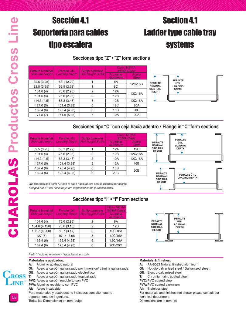
CH
AR
OLA
S P
rodu
ctos
Cro
ss L
ine
58
Sección 4.1Soportería para cables
tipo escalera
Section 4.1Ladder type cable tray
systemsSecciones tipo “Z” • “Z” form sections
Secciones tipo “C” con ceja hacia adentro • Flange in “C” form sections
Secciónes tipo “I” • “I” Form sections
Peralte NominalSide rail height
Peralte ÚtilLoading Depth
Sufijo p/peralteRail height Suffix
Clase NEMANEMA Class
AluminioAluminum
AceroSteel
82.5 (3.25) 58.1 (2.29) 1 8A12C/16B
82.5 (3.25) 56.5 (2.22) 1 8C101.6 (4) 75.6 (2.98) 2 12A
12C/16A101.6 (4) 75.6 (2.98) 2 12B
114.3 (4.5) 88.3 (3.48) 3 12B 12C/16A127.0 (5) 101.4 (3.98) 5 12C 20A152.4 (6) 126.4 (4.98) 6 16C 20C177.8 (7) 151.9 (5.98) 7 12A 20A
Peralte NominalSide rail height
Peralte ÚtilLoading Depth
Sufijo p/peralteRail height Suffix
Clase NEMANEMA Class
AluminioAluminum
AceroSteel
82.5 (3.25) 58.1 (2.29) 1 12A 12B101.6 (4) 75.6 (2.98) 2 12B 12C/16A
114.3 (4.5) 88.3 (3.48) 3 12A 12C/16A127.0 (5) 101.4 (3.98) 5 12A 16B152.4 (6) 126.4 (4.98) 6 16C
20B152.4 (6) 126.4 (4.98) 6 20C
Peralte NominalSide rail height
Peralte ÚtilLoading Depth
Sufijo p/peralteRail height Suffix
Clase NEMANEMA Class
AluminioAluminum
101.6 (4) 75.6 (2.98) 2 8A104.6 (4.120) 78.6 (3.10) 2 12B106.7 (4.200) 80.7 (3.17) 2 12C/16A
127 (5) 101.4 (3.98 5 12C/16A152.4 (6) 126.4 (4.98) 6 12C/16A152.4 (6) 126.4 (4.98) 6 20B/20C
Las charolas con perfil “C” con el patín hacia afuera son solicitadas por escrito.Flanged out “C” rail cable trays are requested in the purchase order.
Perfil “I” solo en Aluminio • I form Aluminum only
Materiales y acabados:A: Aluminio acabado natural GI: Acero al carbón galvanizado por inmersión/ Lámina galvanizadaGE: Acero al carbón galvanizado electrolíticoT: Acero al carbón galvanizado tropicalizadoPVC: Acero al carbón recubierto con PVCPVA: Aluminio recubierto con PVCAI: Acero inoxidablePara materiales y acabados no indicados consulte nuestro departamento de ingeniería.Todas las Dimensiones en mm (pulg)
Materials&finishes:A: AA-6063 Natural finished aluminumGI: Hot dip galvanized steel / Galvanized sheetGE: Electro galvanized steelT: Chromium-zinc coated steelPVC: PVC coated steelPVA: PVC coated aluminumAI: Stainless steelFor materials and finishes not shown please consult our technical department.Dimensions are in mm (in)
PERALTENOMINALSIDE RAIL
HEIGHT
PERALTENOMINALSIDE RAIL
HEIGHT
PERALTENOMINALSIDE RAIL
HEIGHT
PERALTENOMINALSIDE RAIL
HEIGHT
PERALTEÚTIL
LOADINGDEPTH
PERALTEÚTIL
LOADINGDEPTH
PERALTEÚTIL
LOADINGDEPTH
PERALTE ÚTILLOADING DEPTH
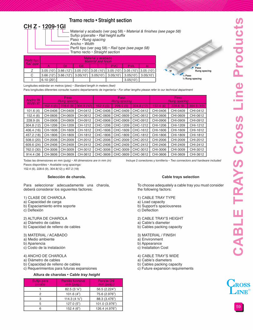
59
CA
BLE
TR
AYS
Cro
ss L
ine
Pro
duct
sTramo recto • Straight section
Perfil tipoRail type
Material y acabadoMaterial and finish
A GI GE T PVC PVA AIZ 3.05 (10’) 3.66 (12’) 3.05 (10’) 3.05 (10’) 3.05 (10’) 3.05 (10’) 3.05 (10’)C 3.66 (12’) 3.66 (12’) 3.05(10’) 3.05(10’) 3.05(10’) 3.05(10’) 3.05(10’)I 6.10 (20’) 3.05(10’)
Ancho WWidth W
PasoRung spacing
PasoRung spacing
PasoRung spacing
152.4 (6) 228.6 (9) 304.8 (12) 152.4 (6) 228.6 (9) 304.8 (12) 152.4 (6) 228.6 (9) 304.8 (12)101.6 (4) CH-0406 CH-0409 CH-0412 CHC-0406 CHC-0409 CHC-0412 CHI-0406 CHI-0409 CHI-0412152.4 (6) CH-0606 CH-0609 CH-0612 CHC-0606 CHC-0609 CHC-0612 CHI-0606 CHI-0609 CHI-0612228.9 (9) CH-0906 CH-0909 CH-0912 CHC-0906 CHC-0909 CHC-0912 CHI-0906 CHI-0909 CHI-0912
304.8 (12) CH-1206 CH-1209 CH-1212 CHC-1206 CHC-1209 CHC-1212 CHI-1206 CHI-1209 CHI-1212406.4 (16) CH-1606 CH-1609 CH-1612 CHC-1606 CHC-1609 CHC-1612 CHI-1606 CHI-1609 CHI-1612457.2 (18) CH-1806 CH-1809 CH-1812 CHC-1806 CHC-1809 CHC-1812 CHI-1806 CHI-1809 CHI-1812508.0 (20) CH-2006 CH-2009 CH-2012 CHC-2006 CHC-2009 CHC-2012 CHI-2006 CHI-2009 CHI-2012609.6 (24) CH-2406 CH-2409 CH-2412 CHC-2406 CHC-2409 CHC-2412 CHI-2406 CHI-2409 CHI-2412762.0 (30) CH-3006 CH-3009 CH-3012 CHC-3006 CHC-3009 CHC-3012 CHI-3006 CHI-3009 CHI-3012914.4 (36 CH-3606 CH-3609 CH-3612 CHC-3606 CHC-3609 CHC-3612 CHI-3606 CHI-3609 CHI-3612
CH Z - 1209-1GIMaterial y acabado (ver pag 58) • Material & finishes (see page 58)Sufijo p/peralte • Rail height suffix Paso • Rung spacingAncho • WidthPerfil tipo (ver pag 58) • Rail type (see page 58)Tramo recto • Straight section
Longitudes estándar en metros (pies) • Standard length in meters (feet)Para longitudes diferentes consulte nuestro departamento de ingeniería • For other lengths please refer to our technical department
Todas las dimensiones en mm (pulg) • All dimensions are in mm (in)Pasos disponibles • Available rung spacings:152.4 (6), 228.6 (9), 304.8(12) y 457.2 (18)
Incluye 2 conectores y tornillería • Two connectors and hardware included
Selección de charola.
Para seleccionar adecuadamente una charola, deberá considerar los siguientes factores:
1) CLASE DE CHAROLAa) Capacidad de carga b) Espaciamiento entre soportec) Deflexión
2) ALTURA DE CHAROLAa) Diámetro de cablesb) Capacidad de relleno de cables
3) MATERIAL / ACABADOa) Medio ambienteb) Aparienciac) Costo de la instalación
4) ANCHO DE CHAROLAa) Diámetro de cablesb) Capacidad de relleno de cablesc) Requerimientos para futuras expansiones
Altura de charolas • Cable tray height
Cable trays selection
To choose adequately a cable tray you must consider the following factors:
1) CABLE TRAY TYPEa) Load capacity b) Support’s spaciousnessc) Deflection
2) CABLE TRAY’S HEIGHTa) Cable’s diameterb) Cables packing capacity
3) MATERIAL / FINISHa) Environmentb) Appearancec) Installation Cost
4) CABLE TRAY’S WIDEa) Cable’s diametersb) Cables packing capacityc) Future expansion requirements
Sufijo para peralte
Peralte Nominalmm (pulg.)
Peralte Útilmm (pulg.)
1 82.5 (3 ¼”) 56.5 (2.224”)2 101.6 (4”) 75.6 (2.976”)3 114.3 (4 ½”) 88.3 (3.476”)5 127.0 (5”) 101.0 (3.976”)6 152.4 (6”) 126.4 (4.976”)
W
½ Paso½ Rung spacing
PasoRung spacing
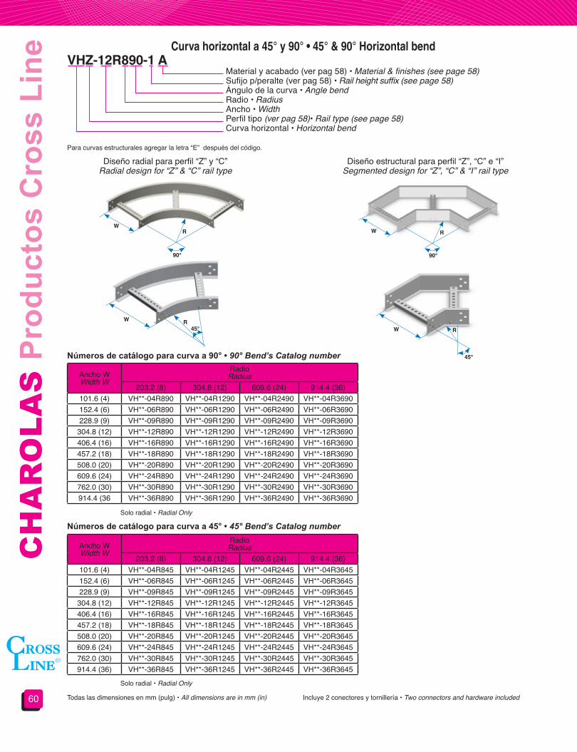
CH
AR
OLA
S P
rodu
ctos
Cro
ss L
ine
60
Curva horizontal a 45° y 90° • 45° & 90° Horizontal bend
Ancho WWidth W
RadioRadius
203.2 (8) 304.8 (12) 609.6 (24) 914.4 (36)101.6 (4) VH**-04R890 VH**-04R1290 VH**-04R2490 VH**-04R3690152.4 (6) VH**-06R890 VH**-06R1290 VH**-06R2490 VH**-06R3690228.9 (9) VH**-09R890 VH**-09R1290 VH**-09R2490 VH**-09R3690
304.8 (12) VH**-12R890 VH**-12R1290 VH**-12R2490 VH**-12R3690406.4 (16) VH**-16R890 VH**-16R1290 VH**-16R2490 VH**-16R3690457.2 (18) VH**-18R890 VH**-18R1290 VH**-18R2490 VH**-18R3690508.0 (20) VH**-20R890 VH**-20R1290 VH**-20R2490 VH**-20R3690609.6 (24) VH**-24R890 VH**-24R1290 VH**-24R2490 VH**-24R3690762.0 (30) VH**-30R890 VH**-30R1290 VH**-30R2490 VH**-30R3690914.4 (36 VH**-36R890 VH**-36R1290 VH**-36R2490 VH**-36R3690
Ancho WWidth W
RadioRadius
203.2 (8) 304.8 (12) 609.6 (24) 914.4 (36)101.6 (4) VH**-04R845 VH**-04R1245 VH**-04R2445 VH**-04R3645152.4 (6) VH**-06R845 VH**-06R1245 VH**-06R2445 VH**-06R3645228.9 (9) VH**-09R845 VH**-09R1245 VH**-09R2445 VH**-09R3645
304.8 (12) VH**-12R845 VH**-12R1245 VH**-12R2445 VH**-12R3645406.4 (16) VH**-16R845 VH**-16R1245 VH**-16R2445 VH**-16R3645457.2 (18) VH**-18R845 VH**-18R1245 VH**-18R2445 VH**-18R3645508.0 (20) VH**-20R845 VH**-20R1245 VH**-20R2445 VH**-20R3645609.6 (24) VH**-24R845 VH**-24R1245 VH**-24R2445 VH**-24R3645762.0 (30) VH**-30R845 VH**-30R1245 VH**-30R2445 VH**-30R3645914.4 (36) VH**-36R845 VH**-36R1245 VH**-36R2445 VH**-36R3645
VHZ-12R890-1 AMaterial y acabado (ver pag 58) • Material & finishes (see page 58)Sufijo p/peralte (ver pag 58) • Rail height suffix (see page 58)Ángulo de la curva • Angle bendRadio • RadiusAncho • WidthPerfil tipo (ver pag 58)• Rail type (see page 58)Curva horizontal • Horizontal bend
Para curvas estructurales agregar la letra “E” después del código.
Números de catálogo para curva a 90° • 90° Bend’s Catalog number
Números de catálogo para curva a 45° • 45° Bend’s Catalog number
Diseño radial para perfil “Z” y “C”Radial design for “Z” & “C” rail type
Diseño estructural para perfil “Z”, “C” e “I”Segmented design for “Z”, “C” & “I” rail type
Todas las dimensiones en mm (pulg) • All dimensions are in mm (in)
Solo radial • Radial Only
Solo radial • Radial Only
Incluye 2 conectores y tornillería • Two connectors and hardware included
W
WW
WR
RR
R
90° 90°
45°
45°

61
CA
BLE
TR
AYS
Cro
ss L
ine
Pro
duct
sCurva vertical exterior a 45° Y 90° • 45° & 90° Outside vertical bendVEZ-12R890-1 A
Material y acabado (ver pag 58) • Material & finishes (see page 58)Sufijo p/peralte (ver pag 58) • Rail height suffix (see page 58)Ángulo de la curva • Angle bendRadio • RadiusAncho • WidthPerfil tipo (ver pag 58)• Rail type (see page 58)Curva vertical exterior • Outside vertical bend
Diseño radial para perfil “Z” y “C”Radial design for “Z” & “C” rail type
Diseño estructural para perfil “Z”, “C” e “I”Segmented design for “Z”, “C” & “I” rail type
Para curvas estructurales agregar la letra “E” después del código.
Ancho WWidth W
RadioRadius
203.2 (8) 304.8 (12) 609.6 (24) 914.4 (36)101.6 (4) VE**-04R890 VE**-04R1290 VE**-04R2490 VE**-04R3690152.4 (6) VE**-06R890 VE**-06R1290 VE**-06R2490 VE**-06R3690228.9 (9) VE**-09R890 VE**-09R1290 VE**-09R2490 VE**-09R3690
304.8 (12) VE**-12R890 VE**-12R1290 VE**-12R2490 VE**-12R3690406.4 (16) VE**-16R890 VE**-16R1290 VE**-16R2490 VE**-16R3690457.2 (18) VE**-18R890 VE**-18R1290 VE**-18R2490 VE**-18R3690508.0 (20) VE**-20R890 VE**-20R1290 VE**-20R2490 VE**-20R3690609.6 (24) VE**-24R890 VE**-24R1290 VE**-24R2490 VE**-24R3690762.0 (30) VE**-30R890 VE**-30R1290 VE**-30R2490 VE**-30R3690914.4 (36) VE**-36R890 VE**-36R1290 VE**-36R2490 VE**-36R3690
Ancho WWidth W
RadioRadius
203.2 (8) 304.8 (12) 609.6 (24) 914.4 (36)101.6 (4) VE**-04R845 VE**-04R1245 VE**-04R2445 VE**-04R3645152.4 (6) VE**-06R845 VE**-06R1245 VE**-06R2445 VE**-06R3645228.9 (9) VE**-09R845 VE**-09R1245 VE**-09R2445 VE**-09R3645
304.8 (12) VE**-12R845 VE**-12R1245 VE**-12R2445 VE**-12R3645406.4 (16) VE**-16R845 VE**-16R1245 VE**-16R2445 VE**-16R3645457.2 (18) VE**-18R845 VE**-18R1245 VE**-18R2445 VE**-18R3645508.0 (20) VE**-20R845 VE**-20R1245 VE**-20R2445 VE**-20R3645609.6 (24) VE**-24R845 VE**-24R1245 VE**-24R2445 VE**-24R3645762.0 (30) VE**-30R845 VE**-30R1245 VE**-30R2445 VE**-30R3645914.4 (36) VE**-36R845 VE**-36R1245 VE**-36R2445 VE**-36R3645
Números de catálogo para curva a 90° • 90° Bend’s Catalog number
Números de catálogo para curva a 45° • 45° Bend’s Catalog number
Todas las dimensiones en mm (pulg) • All dimensions are in mm (in)
Solo radial • Radial Only
Solo radial • Radial Only
Incluye 2 conectores y tornillería • Two connectors and hardware included
W
W
WW
R
R
R R
90°
90°
45°
45°

CH
AR
OLA
S P
rodu
ctos
Cro
ss L
ine
62
Curva vertical interior a 45° Y 90° • 45° & 90° Inside vertical bend
VIZ-12R890-1 A Material y acabado (ver pag 58) • Material & finishes (see page 58)Sufijo p/peralte (ver pag 58) • Rail height suffix (see page 58)Ángulo de la curva • Angle bendRadio • RadiusAncho • WidthPerfil tipo (ver pag 58)• Rail type (see page 58)Curva vertical interior • Inside vertical bend
Diseño radial para perfil “Z” y “C”Radial design for “Z” & “C” rail type
Diseño estructural para perfil “Z”, “C” e “I”Segmented design for “Z”, “C” & “I” rail type
Para curvas estructurales agregar la letra “E” después del código.
Ancho WWidth W
RadioRadius
203.2 (8) 304.8 (12) 609.6 (24) 914.4 (36)101.6 (4) VI**-04R890 VI**-04R1290 VI**-04R2490 VI**-04R3690152.4 (6) VI**-06R890 VI**-06R1290 VI**-06R2490 VI**-06R3690228.9 (9) VI**-09R890 VI**-09R1290 VI**-09R2490 VI**-09R3690
304.8 (12) VI**-12R890 VI**-12R1290 VI**-12R2490 VI**-12R3690406.4 (16) VI**-16R890 VI**-16R1290 VI**-16R2490 VI**-16R3690457.2 (18) VI**-18R890 VI**-18R1290 VI**-18R2490 VI**-18R3690508.0 (20) VI**-20R890 VI**-20R1290 VI**-20R2490 VI**-20R3690609.6 (24) VI**-24R890 VI**-24R1290 VI**-24R2490 VI**-24R3690762.0 (30) VI**-30R890 VI**-30R1290 VI**-30R2490 VI**-30R3690914.4 (36) VI**-36R890 VI**-36R1290 VI**-36R2490 VI**-36R3690
Ancho WWidth W
RadioRadius
203.2 (8) 304.8 (12) 609.6 (24) 914.4 (36)101.6 (4) VI**-04R845 VI**-04R1245 VI**-04R2445 VI**-04R3645152.4 (6) VI**-06R845 VI**-06R1245 VI**-06R2445 VI**-06R3645228.9 (9) VI**-09R845 VI**-09R1245 VI**-09R2445 VI**-09R3645
304.8 (12) VI**-12R845 VI**-12R1245 VI**-12R2445 VI**-12R3645406.4 (16) VI**-16R845 VI**-16R1245 VI**-16R2445 VI**-16R3645457.2 (18) VI**-18R845 VI**-18R1245 VI**-18R2445 VI**-18R3645508.0 (20) VI**-20R845 VI**-20R1245 VI**-20R2445 VI**-20R3645609.6 (24) VI**-24R845 VI**-24R1245 VI**-24R2445 VI**-24R3645762.0 (30) VI**-30R845 VI**-30R1245 VI**-30R2445 VI**-30R3645914.4 (36) VI**-36R845 VI**-36R1245 VI**-36R2445 VI**-36R3645
Números de catálogo para curva a 90° • 90° Bend’s Catalog number
Números de catálogo para curva a 45° • 45° Bend’s Catalog number
Todas las dimensiones en mm (pulg) • All dimensions are in mm (in)
Solo radial • Radial Only
Solo radial • Radial Only
Incluye 2 conectores y tornillería • Two connectors and hardware included
W W
W
W
R R
R
R
90° 90°45°
45°
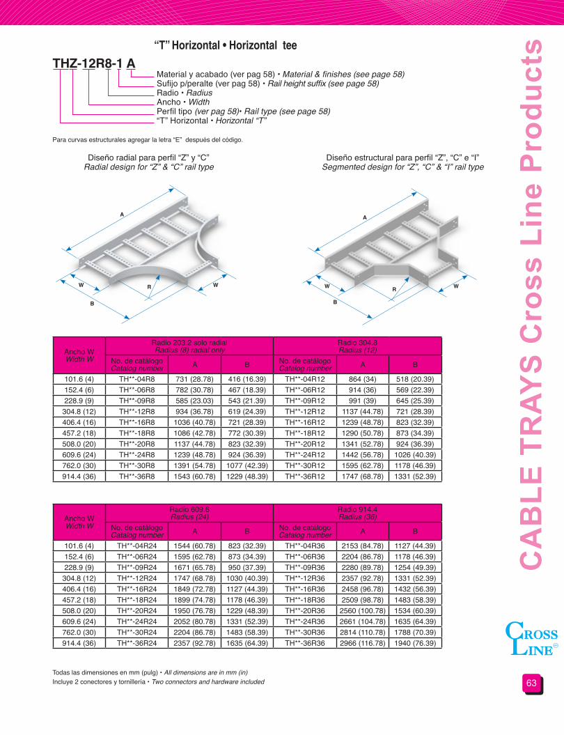
63
CA
BLE
TR
AYS
Cro
ss L
ine
Pro
duct
s“T” Horizontal • Horizontal tee
THZ-12R8-1 AMaterial y acabado (ver pag 58) • Material & finishes (see page 58)Sufijo p/peralte (ver pag 58) • Rail height suffix (see page 58)Radio • RadiusAncho • WidthPerfil tipo (ver pag 58)• Rail type (see page 58)“T” Horizontal • Horizontal “T”
Diseño radial para perfil “Z” y “C”Radial design for “Z” & “C” rail type
Diseño estructural para perfil “Z”, “C” e “I”Segmented design for “Z”, “C” & “I” rail type
Para curvas estructurales agregar la letra “E” después del código.
Ancho WWidth W
Radio 203.2 solo radialRadius (8) radial only
Radio 304.8Radius (12)
No. de catálogoCatalog number A B No. de catálogo
Catalog number A B
101.6 (4) TH**-04R8 731 (28.78) 416 (16.39) TH**-04R12 864 (34) 518 (20.39)152.4 (6) TH**-06R8 782 (30.78) 467 (18.39) TH**-06R12 914 (36) 569 (22.39)228.9 (9) TH**-09R8 585 (23.03) 543 (21.39) TH**-09R12 991 (39) 645 (25.39)
304.8 (12) TH**-12R8 934 (36.78) 619 (24.39) TH**-12R12 1137 (44.78) 721 (28.39)406.4 (16) TH**-16R8 1036 (40.78) 721 (28.39) TH**-16R12 1239 (48.78) 823 (32.39)457.2 (18) TH**-18R8 1086 (42.78) 772 (30.39) TH**-18R12 1290 (50.78) 873 (34.39)508.0 (20) TH**-20R8 1137 (44.78) 823 (32.39) TH**-20R12 1341 (52.78) 924 (36.39)609.6 (24) TH**-24R8 1239 (48.78) 924 (36.39) TH**-24R12 1442 (56.78) 1026 (40.39)762.0 (30) TH**-30R8 1391 (54.78) 1077 (42.39) TH**-30R12 1595 (62.78) 1178 (46.39)914.4 (36) TH**-36R8 1543 (60.78) 1229 (48.39) TH**-36R12 1747 (68.78) 1331 (52.39)
Ancho WWidth W
Radio 609.6Radius (24)
Radio 914.4Radius (36)
No. de catálogoCatalog number A B No. de catálogo
Catalog number A B
101.6 (4) TH**-04R24 1544 (60.78) 823 (32.39) TH**-04R36 2153 (84.78) 1127 (44.39)152.4 (6) TH**-06R24 1595 (62.78) 873 (34.39) TH**-06R36 2204 (86.78) 1178 (46.39)228.9 (9) TH**-09R24 1671 (65.78) 950 (37.39) TH**-09R36 2280 (89.78) 1254 (49.39)
304.8 (12) TH**-12R24 1747 (68.78) 1030 (40.39) TH**-12R36 2357 (92.78) 1331 (52.39)406.4 (16) TH**-16R24 1849 (72.78) 1127 (44.39) TH**-16R36 2458 (96.78) 1432 (56.39)457.2 (18) TH**-18R24 1899 (74.78) 1178 (46.39) TH**-18R36 2509 (98.78) 1483 (58.39)508.0 (20) TH**-20R24 1950 (76.78) 1229 (48.39) TH**-20R36 2560 (100.78) 1534 (60.39)609.6 (24) TH**-24R24 2052 (80.78) 1331 (52.39) TH**-24R36 2661 (104.78) 1635 (64.39)762.0 (30) TH**-30R24 2204 (86.78) 1483 (58.39) TH**-30R36 2814 (110.78) 1788 (70.39)914.4 (36) TH**-36R24 2357 (92.78) 1635 (64.39) TH**-36R36 2966 (116.78) 1940 (76.39)
Todas las dimensiones en mm (pulg) • All dimensions are in mm (in)Incluye 2 conectores y tornillería • Two connectors and hardware included
A A
R R
B B
W WW W
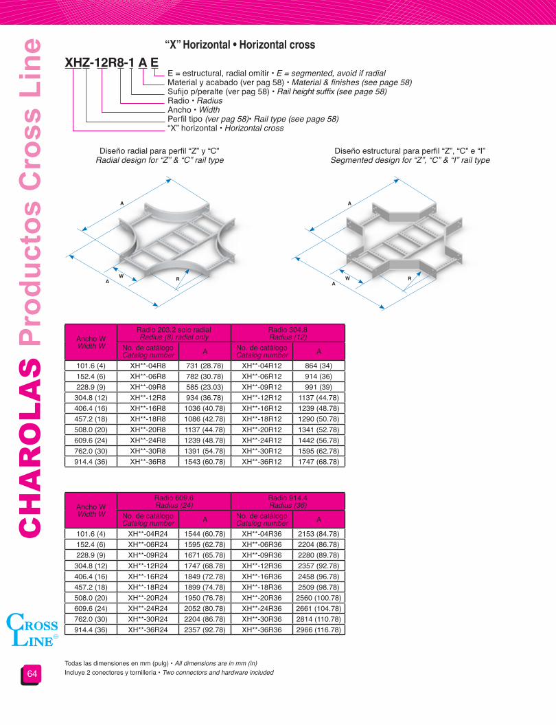
CH
AR
OLA
S P
rodu
ctos
Cro
ss L
ine
64
Ancho WWidth W
Radio 203.2 solo radialRadius (8) radial only
Radio 304.8Radius (12)
No. de catálogoCatalog number A No. de catálogo
Catalog number A
101.6 (4) XH**-04R8 731 (28.78) XH**-04R12 864 (34)152.4 (6) XH**-06R8 782 (30.78) XH**-06R12 914 (36)228.9 (9) XH**-09R8 585 (23.03) XH**-09R12 991 (39)
304.8 (12) XH**-12R8 934 (36.78) XH**-12R12 1137 (44.78)406.4 (16) XH**-16R8 1036 (40.78) XH**-16R12 1239 (48.78)457.2 (18) XH**-18R8 1086 (42.78) XH**-18R12 1290 (50.78)508.0 (20) XH**-20R8 1137 (44.78) XH**-20R12 1341 (52.78)609.6 (24) XH**-24R8 1239 (48.78) XH**-24R12 1442 (56.78)762.0 (30) XH**-30R8 1391 (54.78) XH**-30R12 1595 (62.78)914.4 (36) XH**-36R8 1543 (60.78) XH**-36R12 1747 (68.78)
Ancho WWidth W
Radio 609.6Radius (24)
Radio 914.4Radius (36)
No. de catálogoCatalog number A No. de catálogo
Catalog number A
101.6 (4) XH**-04R24 1544 (60.78) XH**-04R36 2153 (84.78)152.4 (6) XH**-06R24 1595 (62.78) XH**-06R36 2204 (86.78)228.9 (9) XH**-09R24 1671 (65.78) XH**-09R36 2280 (89.78)
304.8 (12) XH**-12R24 1747 (68.78) XH**-12R36 2357 (92.78)406.4 (16) XH**-16R24 1849 (72.78) XH**-16R36 2458 (96.78)457.2 (18) XH**-18R24 1899 (74.78) XH**-18R36 2509 (98.78)508.0 (20) XH**-20R24 1950 (76.78) XH**-20R36 2560 (100.78)609.6 (24) XH**-24R24 2052 (80.78) XH**-24R36 2661 (104.78)762.0 (30) XH**-30R24 2204 (86.78) XH**-30R36 2814 (110.78)914.4 (36) XH**-36R24 2357 (92.78) XH**-36R36 2966 (116.78)
“X” Horizontal • Horizontal cross
XHZ-12R8-1 A EE = estructural, radial omitir • E = segmented, avoid if radialMaterial y acabado (ver pag 58) • Material & finishes (see page 58)Sufijo p/peralte (ver pag 58) • Rail height suffix (see page 58)Radio • RadiusAncho • WidthPerfil tipo (ver pag 58)• Rail type (see page 58)“X” horizontal • Horizontal cross
Diseño radial para perfil “Z” y “C”Radial design for “Z” & “C” rail type
Diseño estructural para perfil “Z”, “C” e “I”Segmented design for “Z”, “C” & “I” rail type
Todas las dimensiones en mm (pulg) • All dimensions are in mm (in)Incluye 2 conectores y tornillería • Two connectors and hardware included
WA R
A
WA
R
A

65
CA
BLE
TR
AYS
Cro
ss L
ine
Pro
duct
s“T” Vertical • Vertical tee
TVZ-12R8-1 A EE = estructural, radial omitir • E = segmented, avoid if radialMaterial y acabado (ver pag 58) • Material & finishes (see page 58)Sufijo p/peralte (ver pag 58) • Rail height suffix (see page 58)Radio • RadiusAncho • WidthPerfil tipo (ver pag 58) • Rail type (see page 58)“T” Vertical • Vertical “T”
Diseño radial para perfil “Z”,radios 203.2 y 304.8 (8 y 12)Radial design for “Z” rail type,radius 203.2 & 304.8 (8 & 12)
Diseño estructural para perfil “Z” y “C” radios 609.6 y 914.4 (24 y 36); perfil “I” radios 203.2, 304.8,
609.6 y 914.4 (8, 12, 24 y 36)Segmented design for “Z” & “C” rail type radius
609.6 & 914.4 (24 & 36); “I” rail type radius 203.2, 304.8, 609.6 & 914.4 (8, 12, 24 & 36)
Ancho WWidth W
RadioRadius
203.2 (8) 304.8 (12) 609.6 (24) 914.4 (36)101.6 (4) TV**-04R8 TV**-04R12 TV**-04R24 TV**-04R36152.4 (6) TV**-06R8 TV**-06R12 TV**-06R24 TV**-06R36228.9 (9) TV**-09R8 TV**-09R12 TV**-09R24 TV**-09R36
304.8 (12) TV**-12R8 TV**-12R12 TV**-12R24 TV**-12R36406.4 (16) TV**-16R8 TV**-16R12 TV**-16R24 TV**-16R36457.2 (18) TV**-18R8 TV**-18R12 TV**-18R24 TV**-18R36508.0 (20) TV**-20R8 TV**-20R12 TV**-20R24 TV**-20R36609.6 (24) TV**-24R8 TV**-24R12 TV**-24R24 TV**-24R36762.0 (30) TV**-30R8 TV**-30R12 TV**-30R24 TV**-30R36914.4 (36) TV**-36R8 TV**-36R12 TV**-36R24 TV**-36R36
Sufijo p/peralteRail height suffix
RadioRadius
203.2 (8) 304.8 (12) 609.6 (24) 914.4 (36)A B A B A B A B
1 489 (19.25) 286 (11.25) 692 (27.25) 387 (15.25) 1302 (51.25) 692 (27.25) 1911 (75.25) 997 (39.25)2 508 (20) 305 (12) 711 (28) 406 (16) 1321 (52) 711 (28) 1930 (76) 1016 (40)3 521 (20.5) 318 (12.5) 724 (28.5) 419 (16.5) 1334 (52.5) 724 (28.5) 1943 (76.5) 1029 (40.5)5 533 (21) 330 (13) 737 (29) 432 (17) 1346 (53) 737 (29) 1956 (77) 1041 (41)6 559 (22) 356 (14) 762 (30) 457 (18) 1372 (54) 762 (30) 1981 (78) 1067 (42)
Todas las dimensiones en mm (pulg) • All dimensions are in mm (in)Incluye 2 conectores y tornillería • Two connectors and hardware included
AW
B
R
A
W
B
R
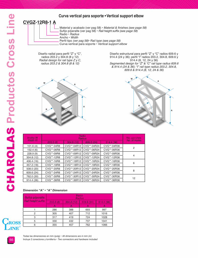
CH
AR
OLA
S P
rodu
ctos
Cro
ss L
ine
66
Diseño radial para perfil “Z” y “C”,radios 203.2 y 304.8 (8 y 12)
Radial design for rail type Z y C,radius 203.2 & 304.8 (8 & 12)
Diseño estructural para perfil “Z” y “C” radios 609.6 y 914.4 (24 y 36); perfil “I” radios 203.2, 304.8, 609.6 y
914.4 (8, 12, 24 y 36)Segmented design for “Z” & “C” rail type radius 609.6
& 914.4 (24 & 36); “I” rail type radius 203.2, 304.8, 609.6 & 914.4 (8, 12, 24 & 36)
Ancho WWidth W
RadioRadius No. ganchos
No. of hooks203.2 (8) 304.8 (12) 609.6 (24) 914.4 (36)
101.6 (4) CVG**-04R8 CVG**-04R12 CVG**-04R24 CVG**-04R362
152.4 (6) CVG**-06R8 CVG**-06R12 CVG**-06R24 CVG**-06R36228.9 (9) CVG**-09R8 CVG**-09R12 CVG**-09R24 CVG**-09R36
4304.8 (12) CVG**-12R8 CVG**-12R12 CVG**-12R24 CVG**-12R36406.4 (16) CVG**-16R8 CVG**-16R12 CVG**-16R24 CVG**-16R36
6457.2 (18) CVG**-18R8 CVG**-18R12 CVG**-18R24 CVG**-18R36508.0 (20) CVG**-20R8 CVG**-20R12 CVG**-20R24 CVG**-20R36
8609.6 (24) CVG**-24R8 CVG**-24R12 CVG**-24R24 CVG**-24R36762.0 (30) CVG**-30R8 CVG**-30R12 CVG**-30R24 CVG**-30R36
12914.4 (36) CVG**-36R8 CVG**-36R12 CVG**-36R24 CVG**-36R36
Sufijo p/peralteRail height suffix
RadioRadius
203.2 (8) 304.8 (12) 609.6 (24) 914.4 (36)A A A A
1 286 388 693 9972 305 407 712 10163 317 419 724 10285 330 432 737 10416 355 457 762 1066
Curva vertical para soporte • Vertical support elbow
CVGZ-12R8-1 AMaterial y acabado (ver pag 58) • Material & finishes (see page 58)Sufijo p/peralte (ver pag 58) • Rail height suffix (see page 58)Radio • RadiusAncho • WidthPerfil tipo (ver pag 58)• Rail type (see page 58)Curva vertical para soporte • Vertical support elbow
Todas las dimensiones en mm (pulg) • All dimensions are in mm (in)Incluye 2 conectores y tornillería • Two connectors and hardware included
AW
AR
AW
A
R
Dimensión “A” • “A” Dimension
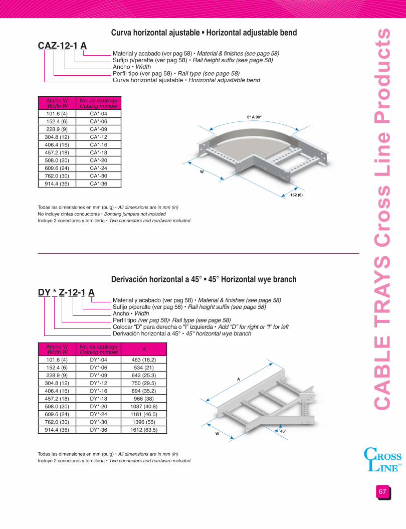
67
CA
BLE
TR
AYS
Cro
ss L
ine
Pro
duct
s
CAZ-12-1 A
DY * Z-12-1 A
Curva horizontal ajustable • Horizontal adjustable bend
Derivación horizontal a 45° • 45° Horizontal wye branch
Material y acabado (ver pag 58) • Material & finishes (see page 58)Sufijo p/peralte (ver pag 58) • Rail height suffix (see page 58)Ancho • WidthPerfil tipo (ver pag 58) • Rail type (see page 58)Curva horizontal ajustable • Horizontal adjustable bend
Material y acabado (ver pag 58) • Material & finishes (see page 58)Sufijo p/peralte (ver pag 58) • Rail height suffix (see page 58)Ancho • WidthPerfil tipo (ver pag 58)• Rail type (see page 58)Colocar “D” para derecha o “I” izquierda • Add “D” for right or “I” for leftDerivación horizontal a 45° • 45° horizontal wye branch
Ancho WWidth W
No. de catálogoCatalog number
101.6 (4) CA*-04152.4 (6) CA*-06228.9 (9) CA*-09
304.8 (12) CA*-12406.4 (16) CA*-16457.2 (18) CA*-18508.0 (20) CA*-20609.6 (24) CA*-24762.0 (30) CA*-30914.4 (36) CA*-36
Ancho WWidth W
No. de catálogoCatalog number A
101.6 (4) DY*-04 463 (18.2)152.4 (6) DY*-06 534 (21)228.9 (9) DY*-09 642 (25.3)
304.8 (12) DY*-12 750 (29.5)406.4 (16) DY*-16 894 (35.2)457.2 (18) DY*-18 966 (38)508.0 (20) DY*-20 1037 (40.8)609.6 (24) DY*-24 1181 (46.5)762.0 (30) DY*-30 1396 (55)914.4 (36) DY*-36 1612 (63.5)
No incluye cintas conductoras • Bonding jumpers not includedTodas las dimensiones en mm (pulg) • All dimensions are in mm (in)
Todas las dimensiones en mm (pulg) • All dimensions are in mm (in)
Incluye 2 conectores y tornillería • Two connectors and hardware included
Incluye 2 conectores y tornillería • Two connectors and hardware included
152 (6)
W
W
A
0° A 90°
45°
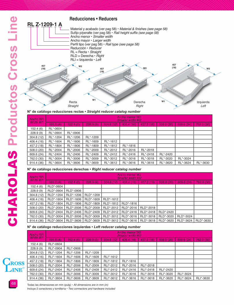
CH
AR
OLA
S P
rodu
ctos
Cro
ss L
ine
68
RectaStraight
DerechaRight
IzquierdaLeft
RL Z-1209-1 AReducciones • Reducers
Material y acabado (ver pag 58) • Material & finishes (see page 58)Sufijo p/peralte (ver pag 58) • Rail height suffix (see page 58)Ancho menor • Smaller widthAncho mayor • Larger widthPerfil tipo (ver pag 58) • Rail type (see page 58)Reducción • ReducerRL = Recta • StraightRLD = Derecha • RightRLI = Izquierda • Left
Todas las dimensiones en mm (pulg) • All dimensions are in mm (in)Incluye 2 conectores y tornillería • Two connectors and hardware included
N° de catálogo reducciones rectas • Straight reducer catalog number
N° de catálogo reducciones derechas • Right reducer catalog number
N° de catálogo reducciones izquierdas • Left reducer catalog number
Ancho W1Width W1
Ancho menor W2Smaller width W2
101.6 (4) 152.4 (6) 228.9 (9) 304.8 (12) 406.4 (16) 457.2 (18) 508.0 (20) 609.6 (24) 762.0 (30)152.4 (6) RL*-0604228.9 (9) RL*-0904 RL*-0906
304.8 (12) RL*-1204 RL*-1206 RL*-1209406.4 (16) RL*-1604 RL*-1606 RL*-1609 RL*-1612457.2 (18) RL*-1804 RL*-1806 RL*-1809 RL*-1812 RL*-1816508.0 (20) RL*-2004 RL*-2006 RL*-2009 RL*-2012 RL*-2016 RL*-2018609.6 (24) RL*-2404 RL*-2406 RL*-2409 RL*-2412 RL*-2416 RL*-2418 RL*-2420762.0 (30) RL*-3004 RL*-3006 RL*-3009 RL*-3012 RL*-3016 RL*-3018 RL*-3020 RL*-3024914.4 (36) RL*-3604 RL*-3606 RL*-3609 RL*-3612 RL*-3616 RL*-3618 RL*-3620 RL*-3624 RL*-3630
Ancho W1Width W1
Ancho menor W2Smaller width W2
101.6 (4) 152.4 (6) 228.9 (9) 304.8 (12) 406.4 (16) 457.2 (18) 508.0 (20) 609.6 (24) 762.0 (30)152.4 (6) RLD*-0604228.9 (9) RLD*-0904 RLD*-0906
304.8 (12) RLD*-1204 RLD*-1206 RLD*-1209406.4 (16) RLD*-1604 RLD*-1606 RLD*-1609 RLD*-1612457.2 (18) RLD*-1804 RLD*-1806 RLD*-1809 RLD*-1812 RLD*-1816508.0 (20) RLD*-2004 RLD*-2006 RLD*-2009 RLD*-2012 RLD*-2016 RLD*-2018609.6 (24) RLD*-2404 RLD*-2406 RLD*-2409 RLD*-2412 RLD*-2416 RLD*-2418 RLD*-2420762.0 (30) RLD*-3004 RLD*-3006 RLD*-3009 RLD*-3012 RLD*-3016 RLD*-3018 RLD*-3020 RLD*-3024914.4 (36) RLD*-3604 RLD*-3606 RLD*-3609 RLD*-3612 RLD*-3616 RLD*-3618 RLD*-3620 RLD*-3624 RLD*-3630
Ancho W1Width W1
Ancho menor W2Smaller width W2
101.6 (4) 152.4 (6) 228.9 (9) 304.8 (12) 406.4 (16) 457.2 (18) 508.0 (20) 609.6 (24) 762.0 (30)152.4 (6) RLI*-0604228.9 (9) RLI*-0904 RLI*-0906
304.8 (12) RLI*-1204 RLI*-1206 RLI*-1209406.4 (16) RLI*-1604 RLI*-1606 RLI*-1609 RLI*-1612457.2 (18) RLI*-1804 RLI*-1806 RLI*-1809 RLI*-1812 RLI*-1816508.0 (20) RLI*-2004 RLI*-2006 RLI*-2009 RLI*-2012 RLI*-2016 RLI*-2018609.6 (24) RLI*-2404 RLI*-2406 RLI*-2409 RLI*-2412 RLI*-2416 RLI*-2418 RLI*-2420762.0 (30) RLI*-3004 RLI*-3006 RLI*-3009 RLI*-3012 RLI*-3016 RLI*-3018 RLI*-3020 RLI*-3024914.4 (36) RLI*-3604 RLI*-3606 RLI*-3609 RLI*-3612 RLI*-3616 RLI*-3618 RLI*-3620 RLI*-3624 RLI*-3630
457(18) 457
(18)
457(18)W2
W2 W2
W1 W1 W1

69
CA
BLE
TR
AYS
Cro
ss L
ine
Pro
duct
sSección 4.2Soportería para cables
tipo fondo sólido y fondo ventilado
Section 4.2Solid and ventilated trough
type cable tray system
Secciónes tipo “Z” • Form “Z” sections
Secciónes tipo “C” • Form “C” sections
Tramo recto • Straight section
Sección típica para tramo rectoStraight typical section
Sección típica para tramo rectoStraight typical section
Sección típica para accesoriosFitting typical section
Sección típica para accesoriosFitting typical section
PERALTE NOMINALSIDE RAIL HEIGHT
PERALTE NOMINALSIDE RAIL HEIGHT
PERALTE NOMINALSIDE RAIL HEIGHT
PERALTE NOMINALSIDE RAIL HEIGHT
CHZP-12-1 AMaterial y acabado • Material & finishesSufijo p/peralte • Rail height suffixAncho • WidthTipo de fondo • Trough typeTramo recto • Straight section
Ancho WWidth W
Perfil tipo Z Form Z
Perfil tipo C C Form
LisoSolid
VentiladoVentilated
LisoSolid
VentiladoVentilated
101.6 (4) CHZL-04 CHZP-04 CHCL-04 CHCP-04152.4 (6) CHZL-06 CHZP-06 CHCL-06 CHCP-06228.9 (9) CHZL-09 CHZP-09 CHCL-09 CHCP-09
304.8 (12) CHZL-12 CHZP-12 CHCL-12 CHCP-12406.4 (16) CHZL-16 CHZP-16 CHCL-16 CHCP-16457.2 (18) CHZL-18 CHZP-18 CHCL-18 CHCP-18508.0 (20) CHZL-20 CHZP-20 CHCL-20 CHCP-20609.6 (24) CHZL-24 CHZP-24 CHCL-24 CHCP-24762.0 (30) CHZL-30 CHZP-30 CHCL-30 CHCP-30914.4 (36) CHZL-36 CHZP-36 CHCL-36 CHCP-36
Materiales y acabados:A: Aluminio aleación AA 3003 acabado naturalGI: Acero al carbón galvanizado por inmersión/ Lámina galvanizadaGE: Acero al carbón Galvanizado electrolíticoT: Acero al carbón TropicalizadoAI: Acero inoxidablePara materiales y acabados no indicados consulte nuestro departamento de ingeniería.Todas las dimensiones en mm (pulg)
Materials&finishes:A: AA-3003 natural finished aluminumGI: Hot dip galvanized steel/ Galvanized sheetGE: Electro galvanized steel T: Chromium-zinc coated steelAI: Stainless steelFor materials and finishes not shown please consult our technical department.All dimensions are in mm (in)
Longitud estándar 3.05 m (10 ft).Para longitudes diferentes consulte nuestro departamento de ingeniería.
Standard lenght 3.05 m (10 ft).For other lenghts refer to our technical departament.Incluye 2 conectores y tornillería • Two connectors and hardware included
W
Sufijo para peralte Peralte Nominal mm (pulg.) Peralte Útil mm (pulg.)0 50.8 (2’’) 50.8 (2’’)1 82.5 (3 ¼”) 82.5 (3 ¼”)2 101.6 (4”) 101.6 (4”)3 114.3 (4 ½”) 114.3 (4 ½”)5 127.0 (5”) 127.0 (5”)6 152.4 (6”) 152.4 (6”)
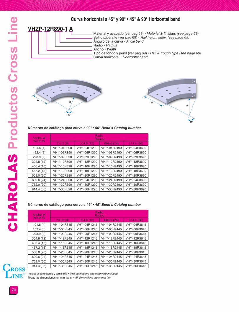
CH
AR
OLA
S P
rodu
ctos
Cro
ss L
ine
70
Curva horizontal a 45° y 90° • 45° & 90° Horizontal bend
VHZP-12R890-1 AMaterial y acabado (ver pag 69) • Material & finishes (see page 69)Sufijo p/peralte (ver pag 69) • Rail height suffix (see page 69)Ángulo de la curva • Angle bendRadio • RadiusAncho • WidthTipo de fondo y perfil (ver pag 69) • Rail & trough type (see page 69)Curva horizontal • Horizontal bend
Números de catálogo para curva a 90° • 90° Bend’s Catalog number
Números de catálogo para curva a 45° • 45° Bend’s Catalog number
Ancho WWidth W
RadioRadius
203.2 (8) 304.8 (12) 609.6 (24) 914.4 (36)101.6 (4) VH**-04R890 VH**-04R1290 VH**-04R2490 VH**-04R3690152.4 (6) VH**-06R890 VH**-06R1290 VH**-06R2490 VH**-06R3690228.9 (9) VH**-09R890 VH**-09R1290 VH**-09R2490 VH**-09R3690
304.8 (12) VH**-12R890 VH**-12R1290 VH**-12R2490 VH**-12R3690406.4 (16) VH**-16R890 VH**-16R1290 VH**-16R2490 VH**-16R3690457.2 (18) VH**-18R890 VH**-18R1290 VH**-18R2490 VH**-18R3690508.0 (20) VH**-20R890 VH**-20R1290 VH**-20R2490 VH**-20R3690609.6 (24) VH**-24R890 VH**-24R1290 VH**-24R2490 VH**-24R3690762.0 (30) VH**-30R890 VH**-30R1290 VH**-30R2490 VH**-30R3690914.4 (36) VH**-36R890 VH**-36R1290 VH**-36R2490 VH**-36R3690
Ancho WWidth W
RadioRadius
203.2 (8) 304.8 (12) 609.6 (24) 914.4 (36)101.6 (4) VH**-04R845 VH**-04R1245 VH**-04R2445 VH**-04R3645152.4 (6) VH**-06R845 VH**-06R1245 VH**-06R2445 VH**-06R3645228.9 (9) VH**-09R845 VH**-09R1245 VH**-09R2445 VH**-09R3645
304.8 (12) VH**-12R845 VH**-12R1245 VH**-12R2445 VH**-12R3645406.4 (16) VH**-16R845 VH**-16R1245 VH**-16R2445 VH**-16R3645457.2 (18) VH**-18R845 VH**-18R1245 VH**-18R2445 VH**-18R3645508.0 (20) VH**-20R845 VH**-20R1245 VH**-20R2445 VH**-20R3645609.6 (24) VH**-24R845 VH**-24R1245 VH**-24R2445 VH**-24R3645762.0 (30) VH**-30R845 VH**-30R1245 VH**-30R2445 VH**-30R3645914.4 (36) VH**-36R845 VH**-36R1245 VH**-36R2445 VH**-36R3645
Todas las dimensiones en mm (pulg) • All dimensions are in mm (in)Incluye 2 conectores y tornillería • Two connectors and hardware included
WWR
R
90°
45°

71
CA
BLE
TR
AYS
Cro
ss L
ine
Pro
duct
sCurva vertical exterior a 45° y 90° • 45° & 90° Outside vertical bend
VEZP-12R890-1 A Material y acabado (ver pag 69) • Material & finishes (see page 69)Sufijo p/peralte (ver pag 69) • Rail height suffix (see page 69)Ángulo de la curva • Angle bendRadio • RadiusAncho • WidthTipo de fondo y perfil (ver pag 69) • Rail & trough type (see page 69)Curva vertical exterior • Outside vertical bend
Números de catálogo para curva a 90° • 90° Bend’s Catalog number
Números de catálogo para curva a 45° • 45° Bend’s Catalog number
Ancho WWidth W
RadioRadius
203.2 (8) 304.8 (12) 609.6 (24) 914.4 (36)101.6 (4) VE**-04R890 VE**-04R1290 VE**-04R2490 VE**-04R3690152.4 (6) VE**-06R890 VE**-06R1290 VE**-06R2490 VE**-06R3690228.9 (9) VE**-09R890 VE**-09R1290 VE**-09R2490 VE**-09R3690
304.8 (12) VE**-12R890 VE**-12R1290 VE**-12R2490 VE**-12R3690406.4 (16) VE**-16R890 VE**-16R1290 VE**-16R2490 VE**-16R3690457.2 (18) VE**-18R890 VE**-18R1290 VE**-18R2490 VE**-18R3690508.0 (20) VE**-20R890 VE**-20R1290 VE**-20R2490 VE**-20R3690609.6 (24) VE**-24R890 VE**-24R1290 VE**-24R2490 VE**-24R3690762.0 (30) VE**-30R890 VE**-30R1290 VE**-30R2490 VE**-30R3690914.4 (36) VE**-36R890 VE**-36R1290 VE**-36R2490 VE**-36R3690
Ancho WWidth W
RadioRadius
203.2 (8) 304.8 (12) 609.6 (24) 914.4 (36)101.6 (4) VE**-04R845 VE**-04R1245 VE**-04R2445 VE**-04R3645152.4 (6) VE**-06R845 VE**-06R1245 VE**-06R2445 VE**-06R3645228.9 (9) VE**-09R845 VE**-09R1245 VE**-09R2445 VE**-09R3645
304.8 (12) VE**-12R845 VE**-12R1245 VE**-12R2445 VE**-12R3645406.4 (16) VE**-16R845 VE**-16R1245 VE**-16R2445 VE**-16R3645457.2 (18) VE**-18R845 VE**-18R1245 VE**-18R2445 VE**-18R3645508.0 (20) VE**-20R845 VE**-20R1245 VE**-20R2445 VE**-20R3645609.6 (24) VE**-24R845 VE**-24R1245 VE**-24R2445 VE**-24R3645762.0 (30) VE**-30R845 VE**-30R1245 VE**-30R2445 VE**-30R3645914.4 (36) VE**-36R845 VE**-36R1245 VE**-36R2445 VE**-36R3645
Todas las dimensiones en mm (pulg) • All dimensions are in mm (in)Incluye 2 conectores y tornillería • Two connectors and hardware included
W
W
R
R90°
45°
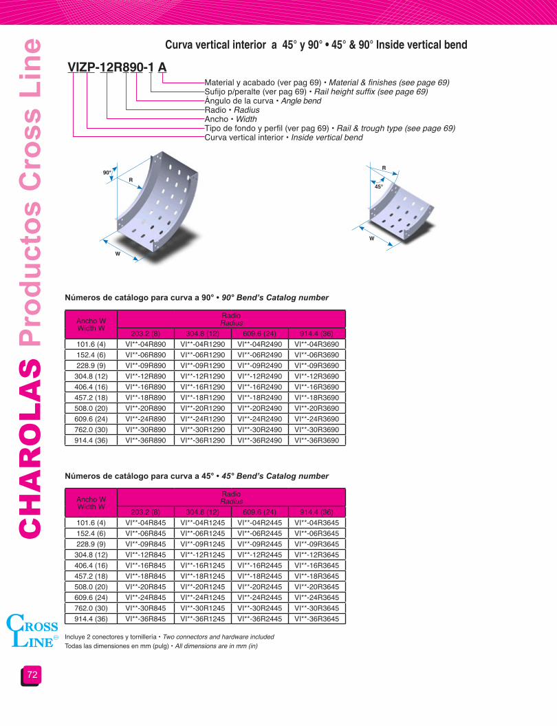
CH
AR
OLA
S P
rodu
ctos
Cro
ss L
ine
72
Curva vertical interior a 45° y 90° • 45° & 90° Inside vertical bend
VIZP-12R890-1 A Material y acabado (ver pag 69) • Material & finishes (see page 69)Sufijo p/peralte (ver pag 69) • Rail height suffix (see page 69)Ángulo de la curva • Angle bendRadio • RadiusAncho • WidthTipo de fondo y perfil (ver pag 69) • Rail & trough type (see page 69)Curva vertical interior • Inside vertical bend
Números de catálogo para curva a 90° • 90° Bend’s Catalog number
Números de catálogo para curva a 45° • 45° Bend’s Catalog number
Ancho WWidth W
RadioRadius
203.2 (8) 304.8 (12) 609.6 (24) 914.4 (36)101.6 (4) VI**-04R890 VI**-04R1290 VI**-04R2490 VI**-04R3690152.4 (6) VI**-06R890 VI**-06R1290 VI**-06R2490 VI**-06R3690228.9 (9) VI**-09R890 VI**-09R1290 VI**-09R2490 VI**-09R3690
304.8 (12) VI**-12R890 VI**-12R1290 VI**-12R2490 VI**-12R3690406.4 (16) VI**-16R890 VI**-16R1290 VI**-16R2490 VI**-16R3690457.2 (18) VI**-18R890 VI**-18R1290 VI**-18R2490 VI**-18R3690508.0 (20) VI**-20R890 VI**-20R1290 VI**-20R2490 VI**-20R3690609.6 (24) VI**-24R890 VI**-24R1290 VI**-24R2490 VI**-24R3690762.0 (30) VI**-30R890 VI**-30R1290 VI**-30R2490 VI**-30R3690914.4 (36) VI**-36R890 VI**-36R1290 VI**-36R2490 VI**-36R3690
Ancho WWidth W
RadioRadius
203.2 (8) 304.8 (12) 609.6 (24) 914.4 (36)101.6 (4) VI**-04R845 VI**-04R1245 VI**-04R2445 VI**-04R3645152.4 (6) VI**-06R845 VI**-06R1245 VI**-06R2445 VI**-06R3645228.9 (9) VI**-09R845 VI**-09R1245 VI**-09R2445 VI**-09R3645
304.8 (12) VI**-12R845 VI**-12R1245 VI**-12R2445 VI**-12R3645406.4 (16) VI**-16R845 VI**-16R1245 VI**-16R2445 VI**-16R3645457.2 (18) VI**-18R845 VI**-18R1245 VI**-18R2445 VI**-18R3645508.0 (20) VI**-20R845 VI**-20R1245 VI**-20R2445 VI**-20R3645609.6 (24) VI**-24R845 VI**-24R1245 VI**-24R2445 VI**-24R3645762.0 (30) VI**-30R845 VI**-30R1245 VI**-30R2445 VI**-30R3645914.4 (36) VI**-36R845 VI**-36R1245 VI**-36R2445 VI**-36R3645
Todas las dimensiones en mm (pulg) • All dimensions are in mm (in)Incluye 2 conectores y tornillería • Two connectors and hardware included
W
W
R
R90°
45°
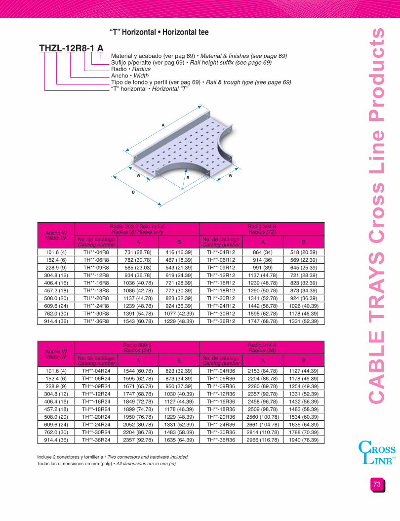
73
CA
BLE
TR
AYS
Cro
ss L
ine
Pro
duct
s“T” Horizontal • Horizontal tee
THZL-12R8-1 AMaterial y acabado (ver pag 69) • Material & finishes (see page 69)Sufijo p/peralte (ver pag 69) • Rail height suffix (see page 69)Radio • RadiusAncho • WidthTipo de fondo y perfil (ver pag 69) • Rail & trough type (see page 69)“T” horizontal • Horizontal “T”
Ancho WWidth W
Radio 203.2 Solo radialRadius (8) Radial only
Radio 304.8Radius (12)
No. de catálogoCatalog number A B No. de catálogo
Catalog number A B
101.6 (4) TH**-04R8 731 (28.78) 416 (16.39) TH**-04R12 864 (34) 518 (20.39)152.4 (6) TH**-06R8 782 (30.78) 467 (18.39) TH**-06R12 914 (36) 569 (22.39)228.9 (9) TH**-09R8 585 (23.03) 543 (21.39) TH**-09R12 991 (39) 645 (25.39)
304.8 (12) TH**-12R8 934 (36.78) 619 (24.39) TH**-12R12 1137 (44.78) 721 (28.39)406.4 (16) TH**-16R8 1036 (40.78) 721 (28.39) TH**-16R12 1239 (48.78) 823 (32.39)457.2 (18) TH**-18R8 1086 (42.78) 772 (30.39) TH**-18R12 1290 (50.78) 873 (34.39)508.0 (20) TH**-20R8 1137 (44.78) 823 (32.39) TH**-20R12 1341 (52.78) 924 (36.39)609.6 (24) TH**-24R8 1239 (48.78) 924 (36.39) TH**-24R12 1442 (56.78) 1026 (40.39)762.0 (30) TH**-30R8 1391 (54.78) 1077 (42.39) TH**-30R12 1595 (62.78) 1178 (46.39)914.4 (36) TH**-36R8 1543 (60.78) 1229 (48.39) TH**-36R12 1747 (68.78) 1331 (52.39)
Ancho WWidth W
Radio 609.6Radius (24)
Radio 914.4Radius (36)
No. de catálogoCatalog number A B No. de catálogo
Catalog number A B
101.6 (4) TH**-04R24 1544 (60.78) 823 (32.39) TH**-04R36 2153 (84.78) 1127 (44.39)152.4 (6) TH**-06R24 1595 (62.78) 873 (34.39) TH**-06R36 2204 (86.78) 1178 (46.39)228.9 (9) TH**-09R24 1671 (65.78) 950 (37.39) TH**-09R36 2280 (89.78) 1254 (49.39)
304.8 (12) TH**-12R24 1747 (68.78) 1030 (40.39) TH**-12R36 2357 (92.78) 1331 (52.39)406.4 (16) TH**-16R24 1849 (72.78) 1127 (44.39) TH**-16R36 2458 (96.78) 1432 (56.39)457.2 (18) TH**-18R24 1899 (74.78) 1178 (46.39) TH**-18R36 2509 (98.78) 1483 (58.39)508.0 (20) TH**-20R24 1950 (76.78) 1229 (48.39) TH**-20R36 2560 (100.78) 1534 (60.39)609.6 (24) TH**-24R24 2052 (80.78) 1331 (52.39) TH**-24R36 2661 (104.78) 1635 (64.39)762.0 (30) TH**-30R24 2204 (86.78) 1483 (58.39) TH**-30R36 2814 (110.78) 1788 (70.39)914.4 (36) TH**-36R24 2357 (92.78) 1635 (64.39) TH**-36R36 2966 (116.78) 1940 (76.39)
Todas las dimensiones en mm (pulg) • All dimensions are in mm (in)Incluye 2 conectores y tornillería • Two connectors and hardware included
WW
B
A
R

CH
AR
OLA
S P
rodu
ctos
Cro
ss L
ine
74
“X” Horizontal • Horizontal cross
XHZP-12R8-1 AMaterial y acabado (ver pag 69) • Material & finishes (see page 69)Sufijo p/peralte (ver pag 69) • Rail height suffix (see page 69)Radio • RadiusAncho • WidthTipo de fondo y perfil (ver pag 69) • Rail & trough type (see page 69)“X” Horizontal • Horizontal cross
Ancho WWidth W
Radio 203.2 Solo radialRadius (8) Radial only
Radio 304.8Radius (12)
No. de catálogoCatalog number A No. de catálogo
Catalog number A
101.6 (4) XH**-04R8 731 (28.78) XH**-04R12 864 (34)152.4 (6) XH**-06R8 782 (30.78) XH**-06R12 914 (36)228.9 (9) XH**-09R8 585 (23.03) XH**-09R12 991 (39)
304.8 (12) XH**-12R8 934 (36.78) XH**-12R12 1137 (44.78)406.4 (16) XH**-16R8 1036 (40.78) XH**-16R12 1239 (48.78)457.2 (18) XH**-18R8 1086 (42.78) XH**-18R12 1290 (50.78)508.0 (20) XH**-20R8 1137 (44.78) XH**-20R12 1341 (52.78)609.6 (24) XH**-24R8 1239 (48.78) XH**-24R12 1442 (56.78)762.0 (30) XH**-30R8 1391 (54.78) XH**-30R12 1595 (62.78)914.4 (36) XH**-36R8 1543 (60.78) XH**-36R12 1747 (68.78)
Ancho WWidth W
Radio 609.6Radius (24)
Radio 914.4Radius (36)
No. de catálogoCatalog number A No. de catálogo
Catalog number A
101.6 (4) XH**-04R24 1544 (60.78) XH**-04R36 2153 (84.78)152.4 (6) XH**-06R24 1595 (62.78) XH**-06R36 2204 (86.78)228.9 (9) XH**-09R24 1671 (65.78) XH**-09R36 2280 (89.78)
304.8 (12) XH**-12R24 1747 (68.78) XH**-12R36 2357 (92.78)406.4 (16) XH**-16R24 1849 (72.78) XH**-16R36 2458 (96.78)457.2 (18) XH**-18R24 1899 (74.78) XH**-18R36 2509 (98.78)508.0 (20) XH**-20R24 1950 (76.78) XH**-20R36 2560 (100.78)609.6 (24) XH**-24R24 2052 (80.78) XH**-24R36 2661 (104.78)762.0 (30) XH**-30R24 2204 (86.78) XH**-30R36 2814 (110.78)914.4 (36) XH**-36R24 2357 (92.78) XH**-36R36 2966 (116.78)
Todas las dimensiones en mm (pulg) • All dimensions are in mm (in)Incluye 2 conectores y tornillería • Two connectors and hardware included
W W
A
AR

75
CA
BLE
TR
AYS
Cro
ss L
ine
Pro
duct
s“T” Vertical • Vertical tee
TVZP-12R8-1 AMaterial y acabado (ver pag 69) • Material & finishes (see page 69)Sufijo p/peralte (ver pag 69) • Rail height suffix (see page 69)Radio • RadiusAncho • WidthTipo de fondo y perfil (ver pag 69) • Rail & trough type (see page 69)“T” vertical • Vertical “T”
Ancho WWidth W
RadioRadius
203.2 (8) 304.8 (12) 609.6 (24) 914.4 (36)101.6 (4) TV**-04R8 TV**-04R12 TV**-04R24 TV**-04R36152.4 (6) TV**-06R8 TV**-06R12 TV**-06R24 TV**-06R36228.9 (9) TV**-09R8 TV**-09R12 TV**-09R24 TV**-09R36
304.8 (12) TV**-12R8 TV**-12R12 TV**-12R24 TV**-12R36406.4 (16) TV**-16R8 TV**-16R12 TV**-16R24 TV**-16R36457.2 (18) TV**-18R8 TV**-18R12 TV**-18R24 TV**-18R36508.0 (20) TV**-20R8 TV**-20R12 TV**-20R24 TV**-20R36609.6 (24) TV**-24R8 TV**-24R12 TV**-24R24 TV**-24R36762.0 (30) TV**-30R8 TV**-30R12 TV**-30R24 TV**-30R36914.4 (36) TV**-36R8 TV**-36R12 TV**-36R24 TV**-36R36
Sufijo p/peralteHeight rail suffix
Radio • Radius203.2 (8) 304.8 (12) 609.6 (24) 914.4 (36)
A B A B A B A B1 489 (19.25) 286 (11.25) 692 (27.25) 387 (15.25) 1302 (51.25) 692 (27.25) 1911 (75.25) 997 (39.25)2 508 (20) 305 (12) 711 (28) 406 (16) 1321 (52) 711 (28) 1930 (76) 1016 (40)3 521 (20.5) 318 (12.5) 724 (28.5) 419 (16.5) 1334 (52.5) 724 (28.5) 1943 (76.5) 1029 (40.5)5 533 (21) 330 (13) 737 (29) 432 (17) 1346 (53) 737 (29) 1956 (77) 1041 (41)6 559 (22) 356 (14) 762 (30) 457 (18) 1372 (54) 762 (30) 1981 (78) 1067 (42)
Todas las dimensiones en mm (pulg) • All dimensions are in mm (in)Incluye 2 conectores y tornillería • Two connectors and hardware included
W
B
A
R

CH
AR
OLA
S P
rodu
ctos
Cro
ss L
ine
76
Curva horizontal ajustable • Horizontal adjustable bend
Derivación horizontal a 45° • 45° Horizontal wye branch
CAZP-12-1 A
DY * ZP-12-1 A
Material y acabado (ver pag 69) • Material & finishes (see page 69)Sufijo p/peralte (ver pag 69) • Rail height suffix (see page 69)Ancho • WidthTipo de fondo y perfil (ver pag 69) • Rail & trough type (see page 69)Curva horizontal ajustable • Horizontal adjustable bend
Material y acabado (ver pag 69) • Material & finishes (see page 69)Sufijo p/peralte (ver pag 69) • Rail height suffix (see page 69)Ancho • WidthTipo de fondo y perfil (ver pag 69) • Rail & trough type (see page 69)Colocar “D” para derecha o “I” izquierda • Add “D” for right or “I” for leftDerivación horizontal a 45° • 45° Horizontal wye branch
Ancho WWidth W
No. de catálogoCatalog number
101.6 (4) CA**-04152.4 (6) CA**-06228.9 (9) CA**-09
304.8 (12) CA**-12406.4 (16) CA**-16457.2 (18) CA**-18508.0 (20) CA**-20609.6 (24) CA**-24762.0 (30) CA**-30914.4 (36) CA**-36
Ancho WWidth W
No. de catálogoCatalog number A
101.6 (4) DY**-04 463 (18.2)152.4 (6) DY**-06 534 (21)228.9 (9) DY**-09 642 (25.3)
304.8 (12) DY**-12 750 (29.5)406.4 (16) DY**-16 894 (35.2)457.2 (18) DY**-18 966 (38)508.0 (20) DY**-20 1037 (40.8)609.6 (24) DY**-24 1181 (46.5)762.0 (30) DY**-30 1396 (55)914.4 (36) DY**-36 1612 (63.5)
Todas las dimensiones en mm (pulg) • All dimensions are in mm (in)
No incluye cintas conductoras • Bonding jumpers not includedTodas las dimensiones en mm (pulg) • All dimensions are in mm (in)
Incluye 2 conectores y tornillería • Two connectors and hardware included
Incluye 2 conectores y tornillería • Two connectors and hardware included
0° A 90°
W
152 (6)
W
A
45°

77
CA
BLE
TR
AYS
Cro
ss L
ine
Pro
duct
s
RectaStraight
DerechaRight
IzquierdaLeft
W2W2
W2
W1 W1W1
457 (18) 457 (18) 457 (18)
RL ZP-1209-1 AReducciones • Reducers
Material y acabado • Material & finishesSufijo p/peralte (ver pag 69) • Rail height suffix (see page 69)Ancho menor • Smaller widthAncho mayor • Larger widthPerfil tipo (ver pag 69) • Rail type (see page 69)Reducción • ReducerRL = Recta • StraightRLD = Derecha • RightRLI = Izquierda • Left
Todas las dimensiones en mm (pulg) • All dimensions are in mm (in)Incluye 2 conectores y tornillería • Two connectors and hardware included
N° de catálogo reducciones rectas • Straight reducer catalog number
N° de catálogo reducciones derechas • Right reducer catalog number
N° de catálogo reducciones izquierdas • Left reducer catalog number
Ancho W1Width W1
Ancho menor W2Smaller width W2
101.6 (4) 152.4 (6) 228.9 (9) 304.8 (12) 406.4 (16) 457.2 (18) 508.0 (20) 609.6 (24) 762.0 (30)152.4 (6) RL**-0604228.9 (9) RL**-0904 RL**-0906
304.8 (12) RL**-1204 RL**-1206 RL**-1209406.4 (16) RL**-1604 RL**-1606 RL**-1609 RL**-1612457.2 (18) RL**-1804 RL**-1806 RL**-1809 RL**-1812 RL**-1816508.0 (20) RL**-2004 RL**-2006 RL**-2009 RL**-2012 RL**-2016 RL**-2018609.6 (24) RL**-2404 RL**-2406 RL**-2409 RL**-2412 RL**-2416 RL**-2418 RL**-2420762.0 (30) RL**-3004 RL**-3006 RL**-3009 RL**-3012 RL**-3016 RL**-3018 RL**-3020 RL**-3024914.4 (36) RL**-3604 RL**-3606 RL**-3609 RL**-3612 RL**-3616 RL**-3618 RL**-3620 RL**-3624 RL**-3630
Ancho W1Width W1
Ancho menor W2Smaller width W2
101.6 (4) 152.4 (6) 228.9 (9) 304.8 (12) 406.4 (16) 457.2 (18) 508.0 (20) 609.6 (24) 762.0 (30)152.4 (6) RLD**-0604228.9 (9) RLD**-0904 RLD**-0906
304.8 (12) RLD**-1204 RLD**-1206 RLD**-1209406.4 (16) RLD**-1604 RLD**-1606 RLD**-1609 RLD**-1612457.2 (18) RLD**-1804 RLD**-1806 RLD**-1809 RLD**-1812 RLD**-1816508.0 (20) RLD**-2004 RLD**-2006 RLD**-2009 RLD**-2012 RLD**-2016 RLD**-2018609.6 (24) RLD**-2404 RLD**-2406 RLD**-2409 RLD**-2412 RLD**-2416 RLD**-2418 RLD**-2420762.0 (30) RLD**-3004 RLD**-3006 RLD**-3009 RLD**-3012 RLD**-3016 RLD**-3018 RLD**-3020 RLD**-3024914.4 (36) RLD**-3604 RLD**-3606 RLD**-3609 RLD**-3612 RLD**-3616 RLD**-3618 RLD**-3620 RLD**-3624 RLD**-3630
Ancho W1Width W1
Ancho menor W2Smaller width W2
101.6 (4) 152.4 (6) 228.9 (9) 304.8 (12) 406.4 (16) 457.2 (18) 508.0 (20) 609.6 (24) 762.0 (30)152.4 (6) RLI**-0604228.9 (9) RLI**-0904 RLI**-0906
304.8 (12) RLI**-1204 RLI**-1206 RLI**-1209406.4 (16) RLI**-1604 RLI**-1606 RLI**-1609 RLI**-1612457.2 (18) RLI**-1804 RLI**-1806 RLI**-1809 RLI**-1812 RLI**-1816508.0 (20) RLI**-2004 RLI**-2006 RLI**-2009 RLI**-2012 RLI**-2016 RLI**-2018609.6 (24) RLI**-2404 RLI**-2406 RLI**-2409 RLI**-2412 RLI**-2416 RLI**-2418 RLI**-2420762.0 (30) RLI**-3004 RLI**-3006 RLI**-3009 RLI**-3012 RLI**-3016 RLI**-3018 RLI**-3020 RLI**-3024914.4 (36) RLI**-3604 RLI**-3606 RLI**-3609 RLI**-3612 RLI**-3616 RLI**-3618 RLI**-3620 RLI**-3624 RLI**-3630
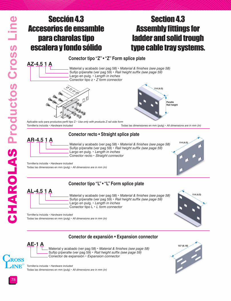
CH
AR
OLA
S P
rodu
ctos
Cro
ss L
ine
78
Todas las dimensiones en mm (pulg) • All dimensions are in mm (in)
Todas las dimensiones en mm (pulg) • All dimensions are in mm (in)
Todas las dimensiones en mm (pulg) • All dimensions are in mm (in)
Todas las dimensiones en mm (pulg) • All dimensions are in mm (in)Tornillería incluida • Hardware included
Tornillería incluida • Hardware included
Tornillería incluida • Hardware included
Tornillería incluida • Hardware included
Aplicable solo para productos perfil tipo Z • Use only with products Z rail side form
Conector tipo “Z” • “Z” Form splice plate
Conector recto • Straight splice plate
Conector tipo “L” • “L” Form splice plate
Conector de expansión • Expansion connector
AZ-4.5 1 A
AR-4.5 1 A
AL-4.5 1 A
AE-1 A
Material y acabado (ver pag 58) • Material & finishes (see page 58)Sufijo p/peralte (ver pag 59) • Rail height suffix (see page 59)Largo en pulg. • Length in inchesConector tipo z • Z form connector
Material y acabado (ver pag 58) • Material & finishes (see page 58)Sufijo p/peralte (ver pag 59) • Rail height suffix (see page 59)Largo en pulg. • Length in inchesConector recto • Straight connector
Material y acabado (ver pag 58) • Material & finishes (see page 58)Sufijo p/peralte (ver pag 59) • Rail height suffix (see page 59)Largo en pulg. • Length in inchesConector tipo L • L form connector
Material y acabado (ver pag 58) • Material & finishes (see page 58)Sufijo p/peralte (ver pag 59) • Rail height suffix (see page 59)Conector de expansión • Expansion connector
PeralteRailheight
114 (4.5)
114 (4.5)
157 (6.18)
114 (4.5)
Sección 4.3Accesorios de ensamble
para charolas tipoescalera y fondo sólido
Section 4.3Assembly fittings for
ladder and solid trough type cable tray systems.
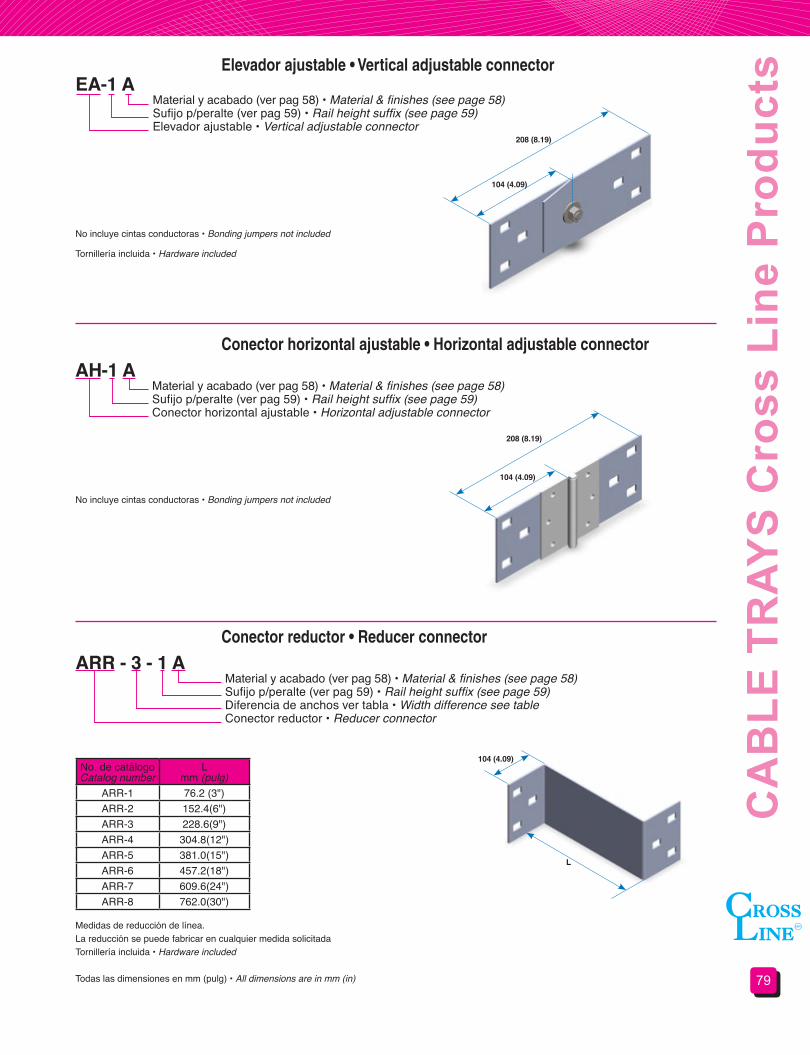
79
CA
BLE
TR
AYS
Cro
ss L
ine
Pro
duct
sElevador ajustable • Vertical adjustable connector
Conector horizontal ajustable • Horizontal adjustable connector
Conector reductor • Reducer connector
EA-1 A
AH-1 A
ARR - 3 - 1 A
Material y acabado (ver pag 58) • Material & finishes (see page 58)Sufijo p/peralte (ver pag 59) • Rail height suffix (see page 59)Elevador ajustable • Vertical adjustable connector
Material y acabado (ver pag 58) • Material & finishes (see page 58)Sufijo p/peralte (ver pag 59) • Rail height suffix (see page 59)Conector horizontal ajustable • Horizontal adjustable connector
Material y acabado (ver pag 58) • Material & finishes (see page 58)Sufijo p/peralte (ver pag 59) • Rail height suffix (see page 59)Diferencia de anchos ver tabla • Width difference see tableConector reductor • Reducer connector
208 (8.19)
208 (8.19)
104 (4.09)
104 (4.09)
104 (4.09)
L
No incluye cintas conductoras • Bonding jumpers not included
No incluye cintas conductoras • Bonding jumpers not included
Tornillería incluida • Hardware included
Medidas de reducción de línea.La reducción se puede fabricar en cualquier medida solicitadaTornillería incluida • Hardware included
Todas las dimensiones en mm (pulg) • All dimensions are in mm (in)
No. de catálogoCatalog number
Lmm (pulg)
ARR-1 76.2 (3")ARR-2 152.4(6")ARR-3 228.6(9")ARR-4 304.8(12")ARR-5 381.0(15")ARR-6 457.2(18")ARR-7 609.6(24")ARR-8 762.0(30")

CH
AR
OLA
S P
rodu
ctos
Cro
ss L
ine
80
Tapa terminal • Blind end
Conector de charola a caja • Frame type box connector
Bajada para cable • Drop-out
PTR-09-1 A
ACC-09-1 A
BC-509-1 A
Material y acabado (ver pag 58) • Material & finishes (see page 58)Sufijo p/peralte (ver pag 59) • Rail height suffix (see page 59)Ancho de la charola • Cable tray widthTapa terminal • Blind end
Material y acabado (ver pag 58) • Material & finishes (see page 58)Sufijo p/peralte (ver pag 59) • Rail height suffix (see page 59)Ancho de la charola • Cable tray widthConector charola a caja • Frame type box connector
Material y acabado (ver pag 58) • Material & finishes (see page 58)Sufijo p/peralte (ver pag 59) • Rail height suffix (see page 59)Ancho de la charola • Cable tray widthRadio de la bajada • Drop-out radiusBajada para cables • Drop-out
W1
W1
W1
R
Tornillería incluida • Hardware included
Tornillería incluida • Hardware included
Tornillería no incluida • Hardware not included
Todas las dimensiones en mm (pulg) • All dimensions are in mm (in)
Ancho de CharolaTray Width W1
101.6 (4) 106(4.19)152.4 (6) 157 (6.19)228.9 (9) 233 (6.19)
304.8 (12) 309 (12.19)406.4 (16) 411 (16.19)457.2 (18) 462 (18.19)508.0 (20) 513 (20.19)609.6 (24) 614 (24.19)762.0 (30) 767 (30.19)914.4 (36) 919 (36.19)
Ancho de CharolaTray Width W1
101.6 (4) 106(4.19)152.4 (6) 157 (6.19)228.9 (9) 233 (6.19)
304.8 (12) 309 (12.19)406.4 (16) 411 (16.19)457.2 (18) 462 (18.19)508.0 (20) 513 (20.19)609.6 (24) 614 (24.19)762.0 (30) 767 (30.19)914.4 (36) 919 (36.19)
Ancho de CharolaTray Width
Radio 50.8Radius (2)
Radio 127Radius (5)
101.6 (4) BC-204 BC-504152.4 (6) BC-206 BC-506228.9 (9) BC-209 BC-509
304.8 (12) BC-212 BC-512406.4 (16) BC-216 BC-516457.2 (18) BC-218 BC-518508.0 (20) BC-220 BC-520609.6 (24) BC-224 BC-524762.0 (30) BC-230 BC-530914.4 (36) BC-236 BC-536
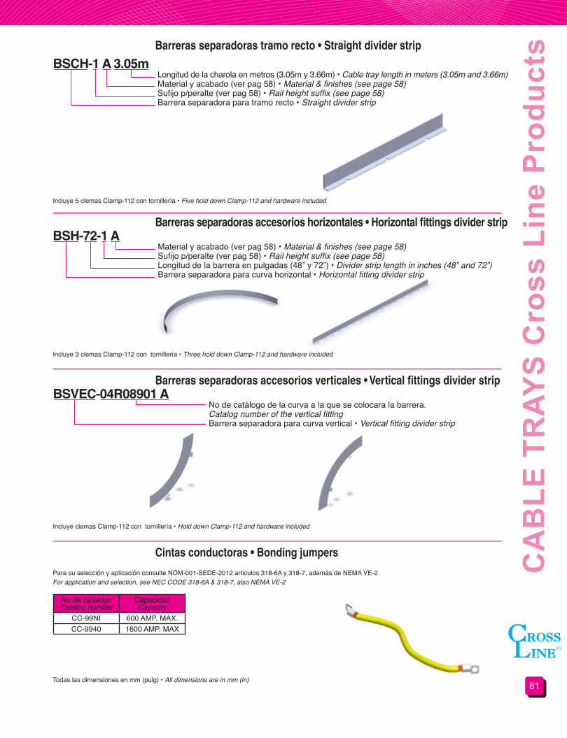
81
CA
BLE
TR
AYS
Cro
ss L
ine
Pro
duct
sBarreras separadoras tramo recto • Straight divider strip
Barreras separadoras accesorios horizontales • Horizontal fittings divider strip
Barreras separadoras accesorios verticales • Vertical fittings divider strip
Cintas conductoras • Bonding jumpers
BSCH-1 A 3.05m
BSH-72-1 A
BSVEC-04R08901 A
Longitud de la charola en metros (3.05m y 3.66m) • Cable tray length in meters (3.05m and 3.66m)Material y acabado (ver pag 58) • Material & finishes (see page 58)Sufijo p/peralte (ver pag 58) • Rail height suffix (see page 58)Barrera separadora para tramo recto • Straight divider strip
Material y acabado (ver pag 58) • Material & finishes (see page 58)Sufijo p/peralte (ver pag 58) • Rail height suffix (see page 58)Longitud de la barrera en pulgadas (48” y 72”) • Divider strip length in inches (48” and 72”)Barrera separadora para curva horizontal • Horizontal fitting divider strip
No de catálogo de la curva a la que se colocara la barrera.Catalog number of the vertical fittingBarrera separadora para curva vertical • Vertical fitting divider strip
Incluye 5 clemas Clamp-112 con tornillería • Five hold down Clamp-112 and hardware included
Incluye 3 clemas Clamp-112 con tornillería • Three hold down Clamp-112 and hardware included
Para su selección y aplicación consulte NOM-001-SEDE-2012 artículos 318-6A y 318-7, además de NEMA VE-2For application and selection, see NEC CODE 318-6A & 318-7, also NEMA VE-2
Incluye clemas Clamp-112 con tornillería • Hold down Clamp-112 and hardware included
Todas las dimensiones en mm (pulg) • All dimensions are in mm (in)
No de catálogoCatalog number
CapacidadCapacity
CC-99NI 600 AMP. MAX.CC-9940 1600 AMP. MAX
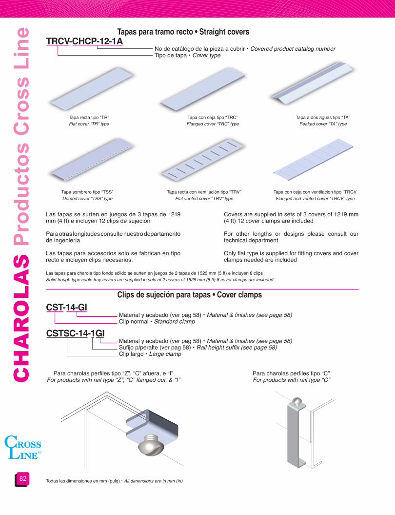
CH
AR
OLA
S P
rodu
ctos
Cro
ss L
ine
82
Tapas para tramo recto • Straight covers
Clips de sujeción para tapas • Cover clamps
TRCV-CHCP-12-1A
CST-14-GI
CSTSC-14-1GI
No de catálogo de la pieza a cubrir • Covered product catalog numberTipo de tapa • Cover type
Material y acabado (ver pag 58) • Material & finishes (see page 58)Clip normal • Standard clamp
Material y acabado (ver pag 58) • Material & finishes (see page 58)Sufijo p/peralte (ver pag 58) • Rail height suffix (see page 58)Clip largo • Large clamp
Tapa recta tipo “TR”Flat cover “TR” type
Tapa sombrero tipo “TSS”Domed cover “TSS” type
Tapa con ceja tipo “TRC”Flanged cover “TRC” type
Tapa recta con ventilación tipo “TRV”Flat vented cover “TRV” type
Tapa a dos aguas tipo “TA”Peaked cover “TA” type
Tapa con ceja con ventilación tipo “TRCVFlanged and vented cover “TRCV” type
Todas las dimensiones en mm (pulg) • All dimensions are in mm (in)
Las tapas se surten en juegos de 3 tapas de 1219 mm (4 ft) e incluyen 12 clips de sujeción
Para otras longitudes consulte nuestro departamento de ingeniería
Las tapas para accesorios solo se fabrican en tipo recto e incluyen clips necesarios.
Covers are supplied in sets of 3 covers of 1219 mm (4 ft) 12 cover clamps are included
For other lengths or designs please consult our technical department
Only flat type is supplied for fitting covers and cover clamps needed are included
Para charolas perfiles tipo “Z”, “C” afuera, e “I”For products with rail type “Z”, “C” flanged out, & “I”
Para charolas perfiles tipo “C” For products with rail type “C”
Las tapas para charola tipo fondo sólido se surten en juegos de 2 tapas de 1525 mm (5 ft) e incluyen 8 clipsSolid trough type cable tray covers are supplied in sets of 2 covers of 1525 mm (5 ft) 8 cover clamps are included.

83
CA
BLE
TR
AYS
Cro
ss L
ine
Pro
duct
sSección 4.4Accesorios de montaje
Section 4.4Supports and brackets
Ménsula para montaje en pared • Wall cantilever bracket
MPPI-09-GIMaterial y acabado • Material & finishes Ancho de la charola • Cable tray widthColocar esta letra para charolas con perfil tipo “C” hacia fuera, e “I”Use this letter for “C” flange out & “I” rail traysMénsula para pared • Wall supported bracket
Ancho de charolaTray width A No de catálogo
Catalog number L No de catálogoCatalog number L Carga soportada
Load capacity101.6 (4)
120 (4.75)
MPP-04 127 (5) MPPI-04 152 (6) 705 kg (1550 lb)152.4 (6) MPP-06 178 (7) MPPI-06 203 (8) 665 kg (1460 lb)228.9 (9) MPP-09 254 (10) MPPI-09 279 (11) 645 kg (1420 lb)
304.8 (12) MPP-12 330 (13) MPPI-12 356 (14) 550 kg (1215 lb)406.4 (16)
158 (6.22)
MPP-16 432 (17) MPPI-16 457 (18) 505 kg (1115 lb)457.2 (18) MPP-18 483 (19) MPPI-18 508 (20) 450 kg (990 lb)508.0 (20) MPP-20 533 (21) MPPI-20 559 (22) 385 kg (850 lb)609.6 (24) MPP-24 635 (25) MPPI-24 660 (26) 325 kg (717 lb)762.0 (30) MPP-30 787 (31) MPPI-30 813 (32) 275 kg (607 lb)914.4 (36) MPP-36 940 (37) MPPI-36 965 (38) 225 kg (496 lb)
Para perfil tipo Z, C, I (ligero)(ver pag 58)
For Z, C, I rail type(see page 58)
Para perfil tipo “C” hacia afuera, e “I” (pesado)
(ver pag 58)For “C” flanged out & “I” rail
type (see page 58)
No incluye tornillería ni sistemas de fijación. • Hardware, clamps or anchoring system are not included
Materiales y acabados:GI: Acero al carbón galvanizado por inmersión en caliente GE: Acero al carbón galvanizado electrolítico T: Acero al carbón tropicalizadoPVC: Acero al carbón recubierto con PVCAI: Acero inoxidable Para materiales y acabados no indicados consulte nuestro departamento de ingeniería Todas las dimensiones en mm (pulg)
La carga soportada muestra la capacidad de la ménsula, CROSS LINE no se hace responsable de fallas atribuibles a los sistemas de anclaje o el sustrato de apoyo.
Las cargas soportadas están basadas en un factor de seguridad de 2.5.
The load shown indicates bracket’s load capacity. CROSS LINE is not responsible for failures caused by the anchoring system or wall materials.
Load capacities are based in a 2.5 safety factor.
Materials&finishes:GI: Hot dip galvanized steel GE: Electro galvanized steel T: Chromium-zinc coated steelPVC: PVC coated steelAI: Stainless steelFor materials and finishes not shown please consult our technical departmentAll dimensions are in mm (in)
14.3 (9/16)
L
A
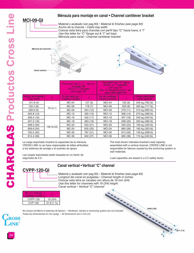
CH
AR
OLA
S P
rodu
ctos
Cro
ss L
ine
84
Ménsula para montaje en canal • Channel cantilever bracket
Canal vertical • Vertical “C” channel
MCI-09-GI
CVPP-120-GI
Material y acabado (ver pag 83) • Material & finishes (see page 83)Ancho de la charola • Cable tray widthColocar esta letra para charolas con perfil tipo “C” hacia fuera, e “I”Use this letter for “C” flange out & “I” rail traysMénsula para canal • Channel cantilever bracket
Material y acabado (ver pag 83) • Material & finishes (see page 83)Longitud del canal en pulgadas • Channel length in inchesColocar esta letra en canales con altura de 19 mm (3/4)Use this letter for channels with 19 (3/4) heightCanal vertical • Vertical “C” channel
Ancho de charolaTray width A No de catálogo
Catalog number L No de catálogoCatalog number L Carga soportada
Load capacity101.6 (4)
79 (3.1)
MC-04 127 (5) MCI-04 152 (6) 345 kg (762 lb)152.4 (6) MC-06 178 (7) MCI-06 203 (8) 325 kg (717 lb)228.9 (9) MC-09 254 (10) MCI-09 279 (11) 315 kg (695 lb)
304.8 (12) MC-12 330 (13) MCI-12 356 (14) 270 kg (596 lb)406.4 (16)
158 (6.22)
MC-16 432 (17) MCI-16 457 (18) 245 kg (540 lb)457.2 (18) MC-18 483 (19) MCI-18 508 (20) 220 kg (485 lb)508.0 (20) MC-20 533 (21) MCI-20 559 (22) 190 kg (420 lb)609.6 (24) MC-24 635 (25) MCI-24 660 (26) 160 kg (353 lb)762.0 (30) MC-30 787 (31) MCI-30 813 (32) 135 kg (298 lb)914.4 (36) MC-36 940 (37) MCI-36 965 (38) 110 kg (243 lb)
No de catálogoCatalog number A
CVPP-120 19 (3/4)CVP-120 31.8 (1 ½)
Para perfil tipo Z, C, I (ligero)(ver pag 58)
For Z, C, I rail type(see page 58)
Para perfil tipo “C” hacia afuera, e “I” (pesado)
(ver pag 58)For “C” flanged out & “I” rail
type (see page 58)
La carga soportada muestra la capacidad de la ménsula, CROSS LINE no se hace responsable de fallas atribuibles a los sistemas de anclaje o el sustrato de apoyo.
Las cargas soportadas están basadas en un factor de seguridad de 2.5.
The load shown indicates bracket’s load capacity assembled with a vertical channel, CROSS LINE is not responsible for failures caused by the anchoring system or wall materials.
Load capacities are based in a 2.5 safety factor.
Ménsula de inserción
Canalvertical
3048 (120)
A
38.1 (1.5)
No incluye tornillería ni sistemas de fijación. • Hardware, clamps or anchoring system are not includedTodas las dimensiones en mm (pulg). • All dimensions are in mm (in)
L
A
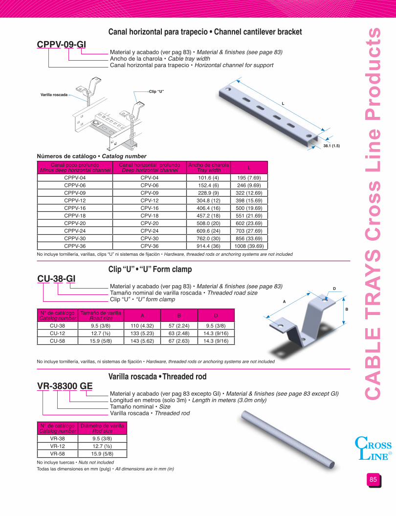
85
CA
BLE
TR
AYS
Cro
ss L
ine
Pro
duct
sCanal horizontal para trapecio • Channel cantilever bracket
Clip “U” • “U” Form clamp
Varilla roscada • Threaded rod
CPPV-09-GI
CU-38-GI
VR-38300 GE
Material y acabado (ver pag 83) • Material & finishes (see page 83)Ancho de la charola • Cable tray widthCanal horizontal para trapecio • Horizontal channel for support
Material y acabado (ver pag 83) • Material & finishes (see page 83)Tamaño nominal de varilla roscada • Threaded road sizeClip “U” • “U” form clamp
Material y acabado (ver pag 83 excepto GI) • Material & finishes (see page 83 except GI)Longitud en metros (solo 3m) • Length in meters (3.0m only)Tamaño nominal • SizeVarilla roscada • Threaded rod
Canal poco profundoMinus deep horizontal channel
Canal horizontal profundoDeep horizontal channel
Ancho de charolaTray width L
CPPV-04 CPV-04 101.6 (4) 195 (7.69)CPPV-06 CPV-06 152.4 (6) 246 (9.69)CPPV-09 CPV-09 228.9 (9) 322 (12.69)CPPV-12 CPV-12 304.8 (12) 398 (15.69)CPPV-16 CPV-16 406.4 (16) 500 (19.69)CPPV-18 CPV-18 457.2 (18) 551 (21.69)CPPV-20 CPV-20 508.0 (20) 602 (23.69)CPPV-24 CPV-24 609.6 (24) 703 (27.69)CPPV-30 CPV-30 762.0 (30) 856 (33.69)CPPV-36 CPV-36 914.4 (36) 1008 (39.69)
N° de catálogoCatalog number
Tamaño de varillaRoad size A B D
CU-38 9.5 (3/8) 110 (4.32) 57 (2.24) 9.5 (3/8)CU-12 12.7 (½) 133 (5.23) 63 (2.48) 14.3 (9/16)CU-58 15.9 (5/8) 143 (5.62) 67 (2.63) 14.3 (9/16)
N° de catálogoCatalog number
Diámetro de varilla Rod size
VR-38 9.5 (3/8)VR-12 12.7 (½)VR-58 15.9 (5/8)
Números de catálogo • Catalog number
Varilla roscadaClip “U”
L
38.1 (1.5)
No incluye tornillería, varillas, clips “U” ni sistemas de fijación • Hardware, threaded rods or anchoring systems are not included
No incluye tornillería, varillas, ni sistemas de fijación • Hardware, threaded rods or anchoring systems are not included
Todas las dimensiones en mm (pulg) • All dimensions are in mm (in)No incluye tuercas • Nuts not included
D
A
B
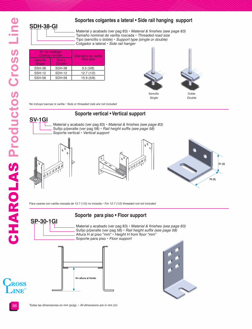
CH
AR
OLA
S P
rodu
ctos
Cro
ss L
ine
86
Soporte vertical • Vertical support
Soportes colgantes a lateral • Side rail hanging support
Soporte para piso • Floor support
SV-1GI
SDH-38-GI
SP-30-1GI
Material y acabado (ver pag 83) • Material & finishes (see page 83)Sufijo p/peralte (ver pag 58) • Rail height suffix (see page 58)Soporte vertical • Vertical support
Material y acabado (ver pag 83) • Material & finishes (see page 83)Tamaño nominal de varilla roscada • Threaded road sizeTipo (sencillo o doble) • Support type (single or double)Colgador a lateral • Side rail hanger
Material y acabado (ver pag 83) • Material & finishes (see page 83)Sufijo p/peralte (ver pag 58) • Rail height suffix (see page 58)Altura H al piso “mm” • Height H from floor “mm”Soporte para piso • Floor support
N° de catálogoCatalog number Diámetro de varilla
Rod sizeSencilloSingle
DobleDouble
SSH-38 SDH-38 9.5 (3/8)SSH-12 SDH-12 12.7 (1/2)SSH-58 SDH-58 15.9 (5/8)
No incluye tuercas ni varilla • Nuts or threaded rods are not included
Para usarse con varilla roscada de 12.7 (1/2) no incluida • For 12.7 (1/2) threaded rod not included
DobleDouble
SencilloSingle
76 (3)
H= altura al fondo
51 (2)
Todas las dimensiones en mm (pulg). • All dimensions are in mm (in)

87
CA
BLE
TR
AYS
Cro
ss L
ine
Pro
duct
sClema para charola • Hold-down clamp
Clips angulares • Angular clamp
CLAMP-112-GI
CAFA-434-GI
Material y acabado (ver pag 83) • Material & finishes (see page 83)Clema para charola • Hold-down clamp
Material y acabado (ver pag 83) • Material & finishes (see page 83)Tipo de clip
Incluye tornillería • Hardware included
Tipo sencilloNo. catálogo CAFC-234
Tipo reforzadoNo. catálogo CAFL-334
Tipo ajustableNo. catálogo CAFC-434
Cople para varilla roscada • Threaded coupling
CVR-38-GEMaterial y acabado (ver pag 83 excepto GI) • Material & finishes (see page 83 except GI)Tamaño nominal • SizeCople para varilla roscada • Threaded coupling
N° de catálogoCatalog number
Diámetro de varilla Rod size
CVR-38 9.5 (3/8)CVR-12 12.7 (½)CVR-58 15.9 (5/8)
Los sistemas de apoyo mostrados en esta sección deberán ser colocados de acuerdo a la norma NEMA VE-2
Frames shown in this section should be installed under NEMA VE 2 standard
Todas las dimensiones en mm (pulg). • All dimensions are in mm (in)

CH
AR
OLA
S P
rodu
ctos
Cro
ss L
ine
88
¡¡¡EN CHAROLAS SEGUIMOS SIENDO SU MEJOR OPCIÓN!!! • IN CABLE TRAY SYSTEMS WE ARE, AGAIN, YOUR BEST CHOICE!!!
El sistema de soportería para cables tipo escalera fabricado en fibra de vidrio marca CROSS LINE es ideal en instalaciones donde se necesita una alta resistencia a la corrosión y donde no se requieran materiales conductores.
Este sistema está diseñado para las condiciones más severas, brindando además el sistema más resistente mecánicamente al tener travesaños atornillados a los perfiles laterales mediante varilla roscada.
Las características que hacen del sistema de fibra de vidrio CROSS LINE, un sistema superior son:
ALTA RESISTENCIA CONTRA RAYOS ULTRAVIOLETA E INTEMPERIE.- Los componentes de poliéster reforzados con fibra de vidrio cuentan con un velo protector aplicado en las superficies exteriores para resistir las inclemencias del tiempo y la acción de los rayos ultravioleta, además, dentro de la formulación, EXCLUSIVA DE CROSS LINE, se integran estabilizadores que aumentan la resistencia, así como pigmentos especiales que sirven como pantalla contra los rayos ultravioleta.
RETARDANTE DE FUEGO.- Por pruebas realizadas en laboratorio y en campo, se demuestra que las charolas evitan la propagación del fuego y auto extinguen cualquier flama en un lapso no mayor a 15 segundos, por otro lado los humos generados durante un evento no son tóxicos a bajas exposiciones.
RESISTENCIA A LA TEMPERATURA.- Las charolas de fibra de vidrio de CROSS LINE tienen un alto grado de resistencia a los cambios de temperatura y a temperaturas extremas, pudiendo ser usadas en cualquier ambiente.
GRAN RESISTENCIA MECÁNICA.- Por su diseño, materiales y método de fabricación estas charolas son más fuertes comparadas con los sistemas metálicos.
FACILIDAD DE INSTALACIÓN.- las charolas de fibra de vidrio son fácilmente perforadas o cortadas con herramientas metálicas, ya que no necesita ser rebabeado. Sus uniones atornillables permiten remover, reponer o trasladar secciones o partes de la instalación.
CROSS LINE’s fiber glass ladder type cable tray system is the best choice for electrical installations where high corrosion resistance and non conductive materials are required.
This system is designed for the most hazardous corrosive environments, being also the most mechanically resistant system as its rungs are bolted to the side rails using threaded rods.
In the following paragraphs we explain why the CROSS LINE fiber glass system is the best choice:
HIGH UV-RAY AND WEATHERING RESISTANCE.- Our fiber glass composite products have an external surface protection veil to protect them against weathering and UV rays.
FLAME RETARDANT.- In field and lab tests, CROSS LINE’s fiber glass products prevent flames spreading and it extinguishes in a no longer than 15 seconds period. Generated smoke is not toxic in low exposures.
TEMPERATURE RESISTANCE.- CROSS LINE’s fiber glass systems have high temperature’s changes resistance grade and can be used in any environment with a good profile.
HIGH MECHANICAL RESISTANCE.- By its design, materials and manufacturing process CROSS LINE’s fiber glass systems are stronger than metallic systems.
EASY INSTALLATION.- CROSS LINE’s fiber glass systems can be easily drilled or cut using metal working tools does not need to be deburred. It’s bolted unions facilitates jobsite removal, replacement and relocate installed parts.
The most important, CROSS LINE’s cable tray systems cover all you need for a complete installation. Straight sections, fittings, connections and covers, all are included in our product line, if you don´t find the accessory you need please consult our technical department..... We can make it.
Sección 4.5Soportería para cables tipo escalera de fibra
de vidrio
Section 4.5Fiber glass ladder type
cable tray systems.

89
CA
BLE
TR
AYS
Cro
ss L
ine
Pro
duct
sSecciónes tipo “C” • “C” Form sections
Tramo recto • Straight section
Peralte NominalSide rail height
Peralte útilLoading depth
Perfil tipoRail type
Sufijo p/peralteRail height Suffix
76. (3) 51 (2)
C, E
3102 (4) 76 (3) 4152 (6) 108 (4 1/4) 6203 (8) 156 (6 1/8) 8
254 (10) 206 (8 1/8) 10
CHC-1209-6FV-6Longitud 6 = 6.10 m 3 = 3.05 m • Length 6 = 20 ft 3 = 10 ftFibra de vidrio • Fiber glassSufijo p/peralte • Rail height suffix Paso • Rung spacingAncho • WidthPerfil tipo • Rail typeTramo recto • Straight section
Ancho WWidth W
PasoRung spacing
152.4 (6) 228.6 (9) 304.8 (12) 457.2 (18)152.4 (6) CHC-0606 CHC-0609 CHC-0612 CHC-0618228.9 (9) CHC-0906 CHC-0909 CHC-0912 CHC-0918
304.8 (12) CHC-1206 CHC-1209 CHC-1212 CHC-1218406.4 (16) CHC-1606 CHC-1609 CHC-1612 CHC-1618457.2 (18) CHC-1806 CHC-1809 CHC-1812 CHC-1818508.0 (20) CHC-2006 CHC-2009 CHC-2012 CHC-2018609.6 (24) CHC-2406 CHC-2409 CHC-2412 CHC-2418762.0 (30) CHC-3006 CHC-3009 CHC-3012 *914.4 (36) CHC-3606 CHC-3609 CHC-3612 *
Números de catálogo • Catalog number
NOTAS :
1. En anchos de 762.0 y 914.4 (30” y 36”) no se fabrican en paso 457 (18”)
2. En pasos de 228.6 y 457.2 (9” y 18”) se consideran nominales y son ajustados a la longitud de la charola.
3. Las longitudes de la charola son de 3.05 m y 6.10 m (10’ y 20’)
NOTES :
1. 762.0 & 914.4 (30” & 36”) widths are not available in 457 (18”) rung spacing.
2. 228.6 & 457.2 (9” & 18”) rung space are considered as nominal and they will be adjusted to the straight section length.
3. Straight sections are available in 3.05 m & 6.10 m (10’ & 20’)
Para longitudes diferentes consulte nuestro departamento de ingeniería. • For any other length please contact our technical department.Incluye conectores y tornillería. • Connectors and hardware included
Todas las dimensiones en mm (pulg). • All dimensions are in mm (in)
W1/2 paso
Paso
Peralte nominalSiderailheight
Peralte útilLoadingdepth

CH
AR
OLA
S P
rodu
ctos
Cro
ss L
ine
90
Curva horizontal a 45° y 90° • 45° & 90° Horizontal bend
VHC-12R1290-4FVFibra de vidrio • Fiber glassSufijo p/peralte (ver pag 89) • Rail height suffix (see page 89)Ángulo de la curva • Angle bendRadio • RadiusAncho • WidthPerfil tipo • Rail typeCurva horizontal • Horizontal bend
Números de catálogo para curva a 90° • 90° Bend’s Catalog number
Números de catálogo para curva a 45° • 45° Bend’s Catalog number
Ancho WWidth W
RadioRadius
304.8 (12) 609.6 (24) 914.4 (36)152.4 (6) VHC-06R1290 VHC-06R2490 VHC-06R3690228.9 (9) VHC-09R1290 VHC-09R2490 VHC-09R3690
304.8 (12) VHC-12R1290 VHC-12R2490 VHC-12R3690406.4 (16) VHC-16R1290 VHC-16R2490 VHC-16R3690457.2 (18) VHC-18R1290 VHC-18R2490 VHC-18R3690508.0 (20) VHC-20R1290 VHC-20R2490 VHC-20R3690609.6 (24) VHC-24R1290 VHC-24R2490 VHC-24R3690762.0 (30) VHC-30R1290 VHC-30R2490 VHC-30R3690914.4 (36) VHC-36R1290 VHC-36R2490 VHC-36R3690
Ancho WWidth W
RadioRadius
304.8 (12) 609.6 (24) 914.4 (36)152.4 (6) VHC-06R1245 VHC-06R2445 VHC-06R3645228.9 (9) VHC-09R1245 VHC-09R2445 VHC-09R3645
304.8 (12) VHC-12R1245 VHC-12R2445 VHC-12R3645406.4 (16) VHC-16R1245 VHC-16R2445 VHC-16R3645457.2 (18) VHC-18R1245 VHC-18R2445 VHC-18R3645508.0 (20) VHC-20R1245 VHC-20R2445 VHC-20R3645609.6 (24) VHC-24R1245 VHC-24R2445 VHC-24R3645762.0 (30) VHC-30R1245 VHC-30R2445 VHC-30R3645914.4 (36) VHC-36R1245 VHC-36R2445 VHC-36R3645
Todas las dimensiones en mm (pulg) • All dimensions are in mm (in)Incluye conectores y tornillería • Connectors and hardware included
W
W
R
R90°
45°
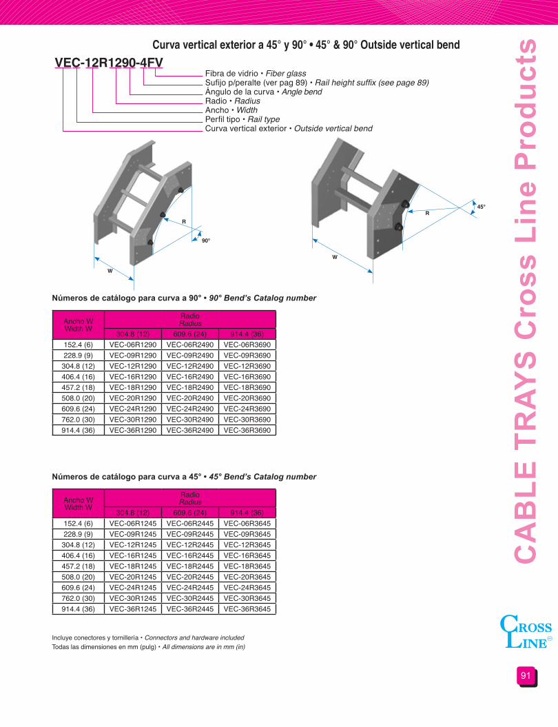
91
CA
BLE
TR
AYS
Cro
ss L
ine
Pro
duct
sCurva vertical exterior a 45° y 90° • 45° & 90° Outside vertical bend
VEC-12R1290-4FVFibra de vidrio • Fiber glassSufijo p/peralte (ver pag 89) • Rail height suffix (see page 89)Ángulo de la curva • Angle bendRadio • RadiusAncho • WidthPerfil tipo • Rail typeCurva vertical exterior • Outside vertical bend
Números de catálogo para curva a 90° • 90° Bend’s Catalog number
Números de catálogo para curva a 45° • 45° Bend’s Catalog number
Ancho WWidth W
RadioRadius
304.8 (12) 609.6 (24) 914.4 (36)152.4 (6) VEC-06R1290 VEC-06R2490 VEC-06R3690228.9 (9) VEC-09R1290 VEC-09R2490 VEC-09R3690
304.8 (12) VEC-12R1290 VEC-12R2490 VEC-12R3690406.4 (16) VEC-16R1290 VEC-16R2490 VEC-16R3690457.2 (18) VEC-18R1290 VEC-18R2490 VEC-18R3690508.0 (20) VEC-20R1290 VEC-20R2490 VEC-20R3690609.6 (24) VEC-24R1290 VEC-24R2490 VEC-24R3690762.0 (30) VEC-30R1290 VEC-30R2490 VEC-30R3690914.4 (36) VEC-36R1290 VEC-36R2490 VEC-36R3690
Ancho WWidth W
RadioRadius
304.8 (12) 609.6 (24) 914.4 (36)152.4 (6) VEC-06R1245 VEC-06R2445 VEC-06R3645228.9 (9) VEC-09R1245 VEC-09R2445 VEC-09R3645
304.8 (12) VEC-12R1245 VEC-12R2445 VEC-12R3645406.4 (16) VEC-16R1245 VEC-16R2445 VEC-16R3645457.2 (18) VEC-18R1245 VEC-18R2445 VEC-18R3645508.0 (20) VEC-20R1245 VEC-20R2445 VEC-20R3645609.6 (24) VEC-24R1245 VEC-24R2445 VEC-24R3645762.0 (30) VEC-30R1245 VEC-30R2445 VEC-30R3645914.4 (36) VEC-36R1245 VEC-36R2445 VEC-36R3645
Todas las dimensiones en mm (pulg) • All dimensions are in mm (in)Incluye conectores y tornillería • Connectors and hardware included
W
W
RR
45°
90°

CH
AR
OLA
S P
rodu
ctos
Cro
ss L
ine
92
W
R90°
Curva vertical interior a 45° y 90° • 45° & 90° Inside vertical bend
VIC-12R1290-4FVFibra de vidrio • Fiber glassSufijo p/peralte (ver pag 89) • Rail height suffix (see page 89)Ángulo de la curva • Angle bendRadio • RadiusAncho • WidthPerfil tipo • Rail typeCurva vertical interior • Inside vertical bend
Números de catálogo para curva a 90° • 90° Bend’s Catalog number
Números de catálogo para curva a 45° • 45° Bend’s Catalog number
Ancho WWidth W
RadioRadius
304.8 (12) 609.6 (24) 914.4 (36)152.4 (6) VIC-06R1290 VIC-06R2490 VIC-06R3690228.9 (9) VIC-09R1290 VIC-09R2490 VIC-09R3690
304.8 (12) VIC-12R1290 VIC-12R2490 VIC-12R3690406.4 (16) VIC-16R1290 VIC-16R2490 VIC-16R3690457.2 (18) VIC-18R1290 VIC-18R2490 VIC-18R3690508.0 (20) VIC-20R1290 VIC-20R2490 VIC-20R3690609.6 (24) VIC-24R1290 VIC-24R2490 VIC-24R3690762.0 (30) VIC-30R1290 VIC-30R2490 VIC-30R3690914.4 (36) VIC-36R1290 VIC-36R2490 VIC-36R3690
Ancho WWidth W
RadioRadius
304.8 (12) 609.6 (24) 914.4 (36)152.4 (6) VIC-06R1245 VIC-06R2445 VIC-06R3645228.9 (9) VIC-09R1245 VIC-09R2445 VIC-09R3645
304.8 (12) VIC-12R1245 VIC-12R2445 VIC-12R3645406.4 (16) VIC-16R1245 VIC-16R2445 VIC-16R3645457.2 (18) VIC-18R1245 VIC-18R2445 VIC-18R3645508.0 (20) VIC-20R1245 VIC-20R2445 VIC-20R3645609.6 (24) VIC-24R1245 VIC-24R2445 VIC-24R3645762.0 (30) VIC-30R1245 VIC-30R2445 VIC-30R3645914.4 (36) VIC-36R1245 VIC-36R2445 VIC-36R3645
Todas las dimensiones en mm (pulg) • All dimensions are in mm (in)Incluye conectores y tornillería • Connectors and hardware included
W
R
45°
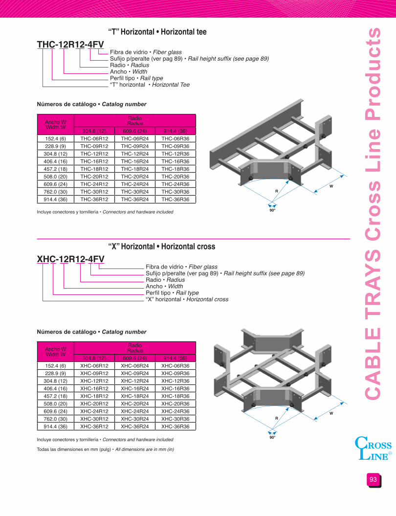
93
CA
BLE
TR
AYS
Cro
ss L
ine
Pro
duct
s“T” Horizontal • Horizontal tee
“X” Horizontal • Horizontal cross
THC-12R12-4FV
XHC-12R12-4FV
Fibra de vidrio • Fiber glassSufijo p/peralte (ver pag 89) • Rail height suffix (see page 89)Radio • RadiusAncho • WidthPerfil tipo • Rail type“T” horizontal • Horizontal Tee
Fibra de vidrio • Fiber glassSufijo p/peralte (ver pag 89) • Rail height suffix (see page 89)Radio • RadiusAncho • WidthPerfil tipo • Rail type“X” horizontal • Horizontal cross
Números de catálogo • Catalog number
Números de catálogo • Catalog number
Ancho WWidth W
RadioRadius
304.8 (12) 609.6 (24) 914.4 (36)152.4 (6) THC-06R12 THC-06R24 THC-06R36228.9 (9) THC-09R12 THC-09R24 THC-09R36
304.8 (12) THC-12R12 THC-12R24 THC-12R36406.4 (16) THC-16R12 THC-16R24 THC-16R36457.2 (18) THC-18R12 THC-18R24 THC-18R36508.0 (20) THC-20R12 THC-20R24 THC-20R36609.6 (24) THC-24R12 THC-24R24 THC-24R36762.0 (30) THC-30R12 THC-30R24 THC-30R36914.4 (36) THC-36R12 THC-36R24 THC-36R36
Ancho WWidth W
RadioRadius
304.8 (12) 609.6 (24) 914.4 (36)152.4 (6) XHC-06R12 XHC-06R24 XHC-06R36228.9 (9) XHC-09R12 XHC-09R24 XHC-09R36
304.8 (12) XHC-12R12 XHC-12R24 XHC-12R36406.4 (16) XHC-16R12 XHC-16R24 XHC-16R36457.2 (18) XHC-18R12 XHC-18R24 XHC-18R36508.0 (20) XHC-20R12 XHC-20R24 XHC-20R36609.6 (24) XHC-24R12 XHC-24R24 XHC-24R36762.0 (30) XHC-30R12 XHC-30R24 XHC-30R36914.4 (36) XHC-36R12 XHC-36R24 XHC-36R36
R
R
W
W
90°
90°
Incluye conectores y tornillería • Connectors and hardware included
Incluye conectores y tornillería • Connectors and hardware included
Todas las dimensiones en mm (pulg) • All dimensions are in mm (in)

CH
AR
OLA
S P
rodu
ctos
Cro
ss L
ine
94
RectaStraight
DerechaRight
IzquierdaLeft
RLC-1209-4FV Reducciones • Reducers
Fibra de vidrio • Fiber glassSufijo p/peralte (ver pag 89) • Rail height suffix (see page 89)Ancho menor • Smaller widthAncho mayor • Larger widthPerfil tipo (ver pag 89) • Rail type (see page 89)Reducción • ReducerRL = Recta • StraightRLD = Derecha • RightRLI = Izquierda • Left
Todas las dimensiones en mm (pulg) • All dimensions are in mm (in)Incluye conectores y tornillería • Connectors and hardware included
N° de catálogo reducciones rectas • Straight reducer catalog number
N° de catálogo reducciones derechas • Right reducer catalog number
N° de catálogo reducciones izquierdas • Left reducer catalog number
Ancho W1Width W1
Ancho menor W2Smaller width W2
152.4 (6) 228.9 (9) 304.8 (12) 406.4 (16) 457.2 (18) 508.0 (20) 609.6 (24) 762.0 (30)152.4 (6)228.9 (9) RLC-0906
304.8 (12) RLC-1206 RLC-1209406.4 (16) RLC-1606 RLC-1609 RLC-1612457.2 (18) RLC-1806 RLC-1809 RLC-1812 RLC-1816508.0 (20) RLC-2006 RLC-2009 RLC-2012 RLC-2016 RLC-2018609.6 (24) RLC-2406 RLC-2409 RLC-2412 RLC-2416 RLC-2418 RLC-2420762.0 (30) RLC-3006 RLC-3009 RLC-3012 RLC-3016 RLC-3018 RLC-3020 RLC-3024914.4 (36) RLC-3606 RLC-3609 RLC-3612 RLC-3616 RLC-3618 RLC-3620 RLC-3624 RLC-3630
Ancho W1Width W1
Ancho menor W2Smaller width W2
152.4 (6) 228.9 (9) 304.8 (12) 406.4 (16) 457.2 (18) 508.0 (20) 609.6 (24) 762.0 (30)152.4 (6)228.9 (9) RLDC-0906
304.8 (12) RLDC-1206 RLDC-1209406.4 (16) RLDC-1606 RLDC-1609 RLDC-1612457.2 (18) RLDC-1806 RLDC-1809 RLDC-1812 RLDC-1816508.0 (20) RLDC-2006 RLDC-2009 RLDC-2012 RLDC-2016 RLDC-2018609.6 (24) RLDC-2406 RLDC-2409 RLDC-2412 RLDC-2416 RLDC-2418 RLDC-2420762.0 (30) RLDC-3006 RLDC-3009 RLDC-3012 RLDC-3016 RLDC-3018 RLDC-3020 RLDC-3024914.4 (36) RLDC-3606 RLDC-3609 RLDC-3612 RLDC-3616 RLDC-3618 RLDC-3620 RLDC-3624 RLDC-3630
Ancho W1Width W1
Ancho menor W2Smaller width W2
152.4 (6) 228.9 (9) 304.8 (12) 406.4 (16) 457.2 (18) 508.0 (20) 609.6 (24) 762.0 (30)152.4 (6)228.9 (9) RLIC-0906
304.8 (12) RLIC-1206 RLIC-1209406.4 (16) RLIC-1606 RLIC-1609 RLIC-1612457.2 (18) RLIC-1806 RLIC-1809 RLIC-1812 RLIC-1816508.0 (20) RLIC-2006 RLIC-2009 RLIC-2012 RLIC-2016 RLIC-2018609.6 (24) RLIC-2406 RLIC-2409 RLIC-2412 RLIC-2416 RLIC-2418 RLIC-2420762.0 (30) RLIC-3006 RLIC-3009 RLIC-3012 RLIC-3016 RLIC-3018 RLIC-3020 RLIC-3024914.4 (36) RLIC-3606 RLIC-3609 RLIC-3612 RLIC-3616 RLIC-3618 RLIC-3620 RLIC-3624 RLIC-3630
W1
W1 W2
W2W2 W1

95
CA
BLE
TR
AYS
Cro
ss L
ine
Pro
duct
s“T” Vertical • Vertical tee
Curva vertical ajustable • Vertical adjustable bend
TVC-12R12-4FV
VAC-12R12-4FV
Fibra de vidrio • Fiber glassSufijo p/peralte (ver pag 89) • Rail height suffix (see page 89)Radio • RadiusAncho • WidthPerfil tipo • Rail type“T” vertical • Vertical Tee
Fibra de vidrio • Fiber glassSufijo p/peralte (ver pag 89) • Rail height suffix (see page 89)Radio • RadiusAncho • WidthPerfil tipo • Rail typeCurva vertical ajustable • Vertical adjustable bend
Ancho WWidth W
RadioRadius
304.8 (12) 609.6 (24) 914.4 (36)152.4 (6) TVC-06R12 TVC-06R24 TVC-06R36228.9 (9) TVC-09R12 TVC-09R24 TVC-09R36
304.8 (12) TVC-12R12 TVC-12R24 TVC-12R36406.4 (16) TVC-16R12 TVC-16R24 TVC-16R36457.2 (18) TVC-18R12 TVC-18R24 TVC-18R36508.0 (20) TVC-20R12 TVC-20R24 TVC-20R36609.6 (24) TVC-24R12 TVC-24R24 TVC-24R36762.0 (30) TVC-30R12 TVC-30R24 TVC-30R36914.4 (36) TVC-36R12 TVC-36R24 TVC-36R36
Ancho WWidth W
RadioRadius
304.8 (12) 609.6 (24) 914.4 (36)152.4 (6) VAC-06R12 VAC-06R24 VAC-06R36228.9 (9) VAC-09R12 VAC-09R24 VAC-09R36
304.8 (12) VAC-12R12 VAC-12R24 VAC-12R36406.4 (16) VAC-16R12 VAC-16R24 VAC-16R36457.2 (18) VAC-18R12 VAC-18R24 VAC-18R36508.0 (20) VAC-20R12 VAC-20R24 VAC-20R36609.6 (24) VAC-24R12 VAC-24R24 VAC-24R36762.0 (30) VAC-30R12 VAC-30R24 VAC-30R36914.4 (36) VAC-36R12 VAC-36R24 VAC-36R36
Todas las dimensiones en mm (pulg) • All dimensions are in mm (in)
Incluye conectores y tornillería • Connectors and hardware included
Incluye conectores y tornillería • Connectors and hardware included
90°W
R
N° de catálogo • Catalog number
N° de catálogo • Catalog number
W
R

CH
AR
OLA
S P
rodu
ctos
Cro
ss L
ine
96
Incluye tornillería de acero inoxidable encapsulados en fibra de vidrio • Stainless steel encased in fiber glass bolts included.
Incluye tornillería de acero inoxidable encapsulados en fibra de vidrio • Stainless steel encased in fiber glass bolts included.
AR Tipo rectoSplice plate AR TYPE
AH Tipo horizontal ajustableHorizontal adjustable AH TYPE
EA Tipo vertical ajustableVertical adjustable EA TYPE
AE Conector de expansiónExpansion connector AE TYPE
Conectores • Connectors
Conectores verticales de ángulo fijo • Fixed angle vertical connectors
Conectores horizontales de ángulo fijo • Fixed angle horizontal connectors
AE-4FV
AV30-4FV
AHF30-4FV
Fibra de vidrio • Fiber glassSufijo p/peralte (ver pag 89) • Rail height suffix (see page 89)Conector tipo • Connector type
Fibra de vidrio • Fiber glassSufijo p/peralte (ver pag 89) • Rail height suffix (see page 89)Conector tipo • Connector type
Fibra de vidrio • Fiber glassSufijo p/peralte (ver pag 89) • Rail height suffix (see page 89)Conector tipo • Connector type
ÁnguloAngle
Conector tipoConnector type
22.5° AV2230° AV3045° AV4560° AV6090° AV90
ÁnguloAngle
Conector tipoConnector type
22.5° AHF2230° AHF3045° AHF4560° AHF6090° AHF90
ÁnguloAngle
ÁnguloAngle
Incluye tornillería de acero inoxidable encapsulados en fibra de vidrio • Stainless steel encased in fiber glass bolts included.SUGERENCIA DE USO: El conector AHF90 puede ser usado en pares como CONECTOR A CAJA.

97
CA
BLE
TR
AYS
Cro
ss L
ine
Pro
duct
s
Todas las dimensiones en mm (pulg) • All dimensions are in mm (in)
Incluye tornillería de acero inoxidable encapsulados en fibra de vidrio • Stainless steel encased in fiber glass bolts included.
Placa terminal • Blind end
Conectores horizontales de ángulo fijo • Fixed angle horizontal connectors
PTR-12-4FV Fibra de vidrio • Fiber glassSufijo p/peralte (ver pag 89) • Rail height suffix (see page 89)Ancho de la charola • Tray widthTapa terminal • Blind end
Tapa recta sin ventilación • Non vented flat cover
Tapa recta con ventilación • Vented flat cover
TR THC-12R12-4FV
TRV THC-12R12-4FV
Fibra de vidrio • Fiber glassSufijo p/peralte (ver pag 89) • Rail height suffix (see page 89)No de catálogo de el producto a recubrir • Covered product catalog numberTapa recta no ventilada • Non vented flat cover
Fibra de vidrio • Fiber glassSufijo p/peralte (ver pag 89) • Rail height suffix (see page 89)No de catálogo de el producto a recubrir • Covered product catalog numberTapa recta ventilada • Vented flat cover
La longitud de la tapa para tramo recto es de 3.048 m.
Cada tapa para tramo recto incluye 6 clips de sujeción de acero inoxidable.
El número de clips para tapas de accesorios estará en función del accesorio.
For straight section, the cover length is 3.048 m (10 ft) and 6 cover clamps are included.
For fittings the cover clamps quantity is according to the fitting.
La longitud de la tapa para tramo recto es de 3.048 m.
Cada tapa para tramo recto incluye 4 pares de juegos de separadores.
El número de clips para tapas de accesorios estará en función del accesorio.
For straight section, the cover length is 3.048 m (10 ft) and 4 pairs cover clamps kits are included.
For fittings the cover clamp quantity is according to the fitting.
The anchorage holes should be field made.

CH
AR
OLA
S P
rodu
ctos
Cro
ss L
ine
98
Las barreras separadoras para tramos rectos se surten en Longitudes de 3.048 metros y deberán ser instaladas en campo.
Cada barrera separadora incluye 3 juegos de clips (placa, y tornillería).
Debido a que es imposible determinar con anticipación la posición de la barrera en un accesorio, cuando se requiera se deberá solicitar barreras para tramos rectos y deberán ser cortadas e instaladas en campo.
For straight section, the barrier length is 3.048 m (10 ft) and 3 barrier clamp kits (platter and hardware) are included.
The barriers should be field installed.
Barreras separadoras • Barrier strips
BSCH-4FV Fibra de vidrio • Fiber glassSufijo p/peralte (ver pag 89) • Rail height suffix (see page 89)Barrera separadora • Barrier strip
Tapa a dos aguas con ventilación • Vented peaked cover
TA CHC-1209-4FV Fibra de vidrio • Fiber glassSufijo p/peralte (ver pag 89) • Rail height suffix (see page 89)No de catálogo de el producto a recubrir • Covered product catalog numberTapa a dos aguas ventilada • Vented peaked cover
La longitud de la tapa es de 3.048 m.
Este tipo de tapa no está disponible para accesorios.
The cover length is 3.048 m (10 ft) and 4 pairs of kits cover clamps are included.
This cover type in not available for fitting.
The anchorage holes should be field made.
Todas las dimensiones en mm (pulg) • All dimensions are in mm (in)
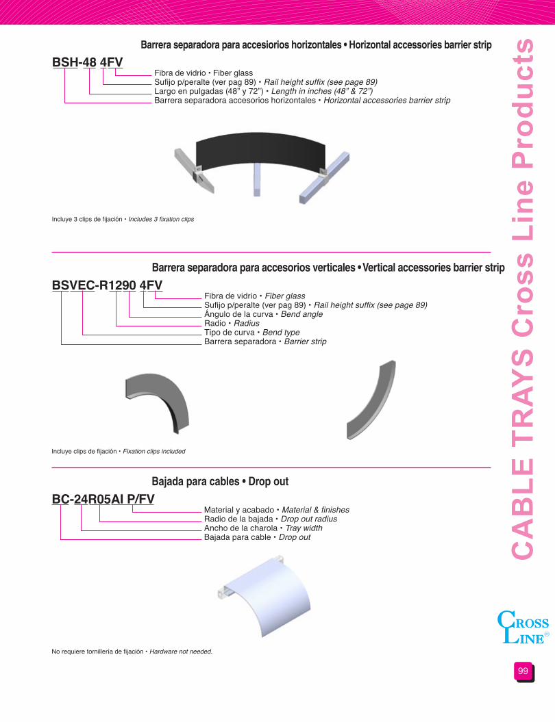
99
CA
BLE
TR
AYS
Cro
ss L
ine
Pro
duct
s
Incluye 3 clips de fijación • Includes 3 fixation clips
Incluye clips de fijación • Fixation clips included
Barrera separadora para accesiorios horizontales • Horizontal accessories barrier strip
Barrera separadora para accesorios verticales • Vertical accessories barrier strip
BSH-48 4FV
BSVEC-R1290 4FV
Fibra de vidrio • Fiber glassSufijo p/peralte (ver pag 89) • Rail height suffix (see page 89)Largo en pulgadas (48” y 72”) • Length in inches (48” & 72”)Barrera separadora accesorios horizontales • Horizontal accessories barrier strip
No requiere tornillería de fijación • Hardware not needed.
Bajada para cables • Drop out
BC-24R05AI P/FVMaterial y acabado • Material & finishesRadio de la bajada • Drop out radiusAncho de la charola • Tray widthBajada para cable • Drop out
Fibra de vidrio • Fiber glassSufijo p/peralte (ver pag 89) • Rail height suffix (see page 89)Ángulo de la curva • Bend angleRadio • RadiusTipo de curva • Bend typeBarrera separadora • Barrier strip
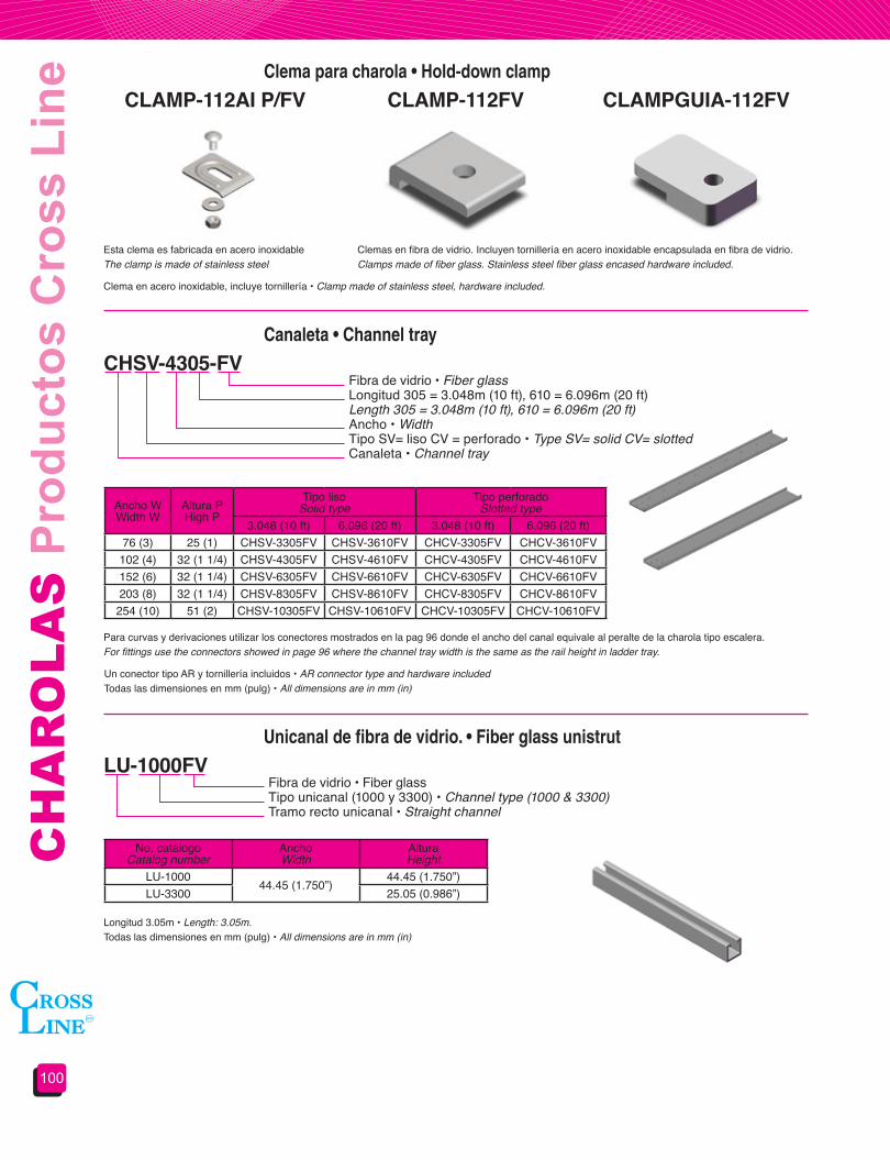
CH
AR
OLA
S P
rodu
ctos
Cro
ss L
ine
100
Longitud 3.05m • Length: 3.05m.Todas las dimensiones en mm (pulg) • All dimensions are in mm (in)
Unicanal de fibra de vidrio. • Fiber glass unistrut
LU-1000FVFibra de vidrio • Fiber glassTipo unicanal (1000 y 3300) • Channel type (1000 & 3300)Tramo recto unicanal • Straight channel
No. catálogoCatalog number
AnchoWidth
AlturaHeight
LU-100044.45 (1.750”)
44.45 (1.750”)LU-3300 25.05 (0.986”)
Un conector tipo AR y tornillería incluidos • AR connector type and hardware includedTodas las dimensiones en mm (pulg) • All dimensions are in mm (in)
Para curvas y derivaciones utilizar los conectores mostrados en la pag 96 donde el ancho del canal equivale al peralte de la charola tipo escalera.For fittings use the connectors showed in page 96 where the channel tray width is the same as the rail height in ladder tray.
Canaleta • Channel tray
CHSV-4305-FV Fibra de vidrio • Fiber glassLongitud 305 = 3.048m (10 ft), 610 = 6.096m (20 ft)Length 305 = 3.048m (10 ft), 610 = 6.096m (20 ft) Ancho • WidthTipo SV= liso CV = perforado • Type SV= solid CV= slottedCanaleta • Channel tray
Ancho WWidth W
Altura PHigh P
Tipo lisoSolid type
Tipo perforado Slotted type
3.048 (10 ft) 6.096 (20 ft) 3.048 (10 ft) 6.096 (20 ft)76 (3) 25 (1) CHSV-3305FV CHSV-3610FV CHCV-3305FV CHCV-3610FV
102 (4) 32 (1 1/4) CHSV-4305FV CHSV-4610FV CHCV-4305FV CHCV-4610FV152 (6) 32 (1 1/4) CHSV-6305FV CHSV-6610FV CHCV-6305FV CHCV-6610FV203 (8) 32 (1 1/4) CHSV-8305FV CHSV-8610FV CHCV-8305FV CHCV-8610FV
254 (10) 51 (2) CHSV-10305FV CHSV-10610FV CHCV-10305FV CHCV-10610FV
Clema en acero inoxidable, incluye tornillería • Clamp made of stainless steel, hardware included.
Clema para charola • Hold-down clamp
CLAMP-112AI P/FV
Clemas en fibra de vidrio. Incluyen tornillería en acero inoxidable encapsulada en fibra de vidrio.Clamps made of fiber glass. Stainless steel fiber glass encased hardware included.
Esta clema es fabricada en acero inoxidable The clamp is made of stainless steel
CLAMP-112FV CLAMPGUIA-112FV
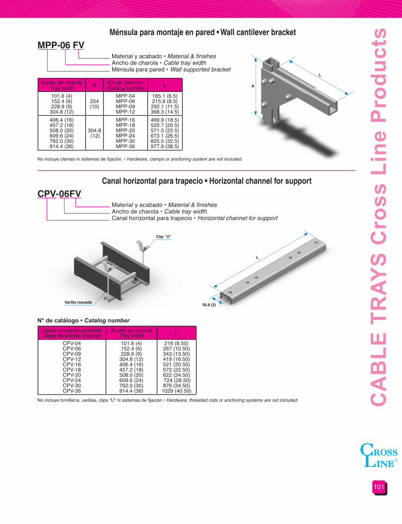
101
CA
BLE
TR
AYS
Cro
ss L
ine
Pro
duct
sMénsula para montaje en pared • Wall cantilever bracket
MPP-06 FVMaterial y acabado • Material & finishesAncho de charola • Cable tray widthMénsula para pared • Wall supported bracket
Ancho de charolaTray width A No de catálogo
Catalog number L
101.6 (4)152.4 (6)228.9 (9)
304.8 (12)
254 (10)
MPP-04MPP-06MPP-09MPP-12
165.1 (6.5)215.9 (8.5)292.1 (11.5)368.3 (14.5)
406.4 (16)457.2 (18)508.0 (20)609.6 (24)762.0 (30)914.4 (36)
304.8 (12)
MPP-16MPP-18MPP-20MPP-24MPP-30MPP-36
469.9 (18.5)520.7 (20.5)571.5 (22.5)673.1 (26.5)825.5 (32.5)977.9 (38.5)
No incluye clemas ni sistemas de fijación. • Hardware, clamps or anchoring system are not included.
Canal horizontal para trapecio • Horizontal channel for support
CPV-06FVMaterial y acabado • Material & finishesAncho de charola • Cable tray widthCanal horizontal para trapecio • Horizontal channel for support
Canal horizontal profundoDeep horizontal channel
Ancho de charolaTray width L
CPV-04CPV-06CPV-09CPV-12CPV-16CPV-18CPV-20CPV-24CPV-30CPV-36
101.6 (4)152.4 (6)228.9 (9)
304.8 (12)406.4 (16)457.2 (18)508.0 (20)609.6 (24)762.0 (30)914.4 (36)
216 (8.50)267 (10.50)343 (13.50)419 (16.50)521 (20.50)572 (22.50)622 (24.50) 724 (28.50)876 (34.50)
1029 (40.50)No incluye tornillería, varillas, clips “U” ni sistemas de fijación • Hardware, threaded rods or anchoring systems are not included.
L
A
L
50.8 (2)
Clip “U”
Varilla roscada
Fibra de vidrio • Fiber glassLongitud 305 = 3.048m (10 ft), 610 = 6.096m (20 ft)Length 305 = 3.048m (10 ft), 610 = 6.096m (20 ft) Ancho • WidthTipo SV= liso CV = perforado • Type SV= solid CV= slottedCanaleta • Channel tray
N° de catálogo • Catalog number
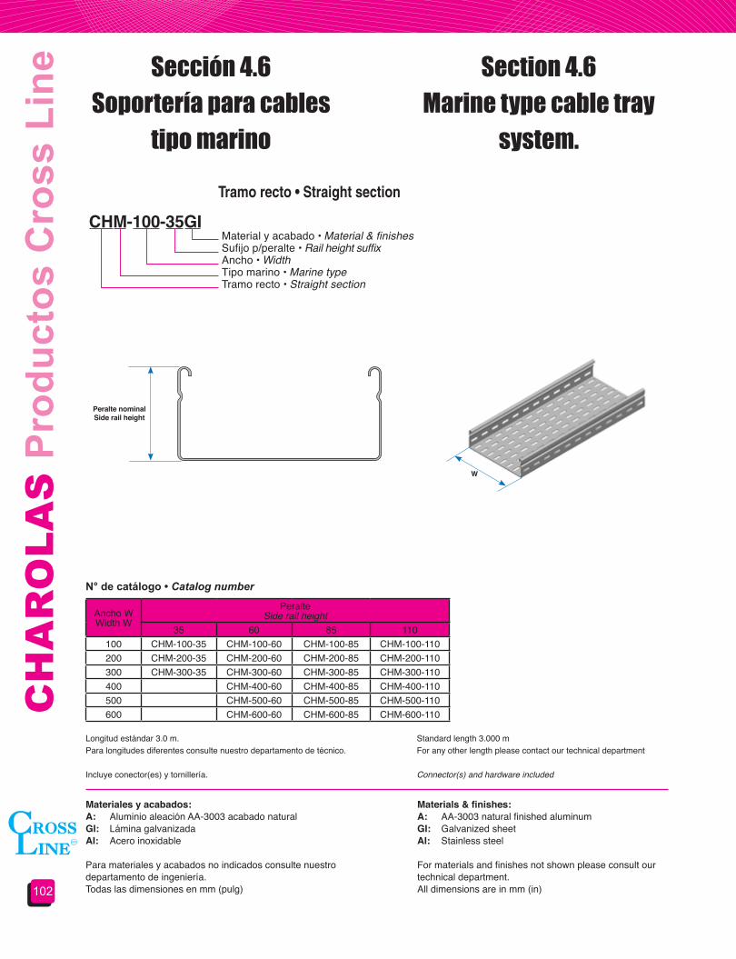
CH
AR
OLA
S P
rodu
ctos
Cro
ss L
ine
102
Ancho WWidth W
PeralteSide rail height
35 60 85 110100 CHM-100-35 CHM-100-60 CHM-100-85 CHM-100-110200 CHM-200-35 CHM-200-60 CHM-200-85 CHM-200-110300 CHM-300-35 CHM-300-60 CHM-300-85 CHM-300-110400 CHM-400-60 CHM-400-85 CHM-400-110500 CHM-500-60 CHM-500-85 CHM-500-110600 CHM-600-60 CHM-600-85 CHM-600-110
Sección 4.6Soportería para cables
tipo marino
Section 4.6Marine type cable tray
system.
Tramo recto • Straight section
CHM-100-35GIMaterial y acabado • Material & finishesSufijo p/peralte • Rail height suffixAncho • WidthTipo marino • Marine typeTramo recto • Straight section
Materiales y acabados:A: Aluminio aleación AA-3003 acabado naturalGI: Lámina galvanizadaAI: Acero inoxidable
Para materiales y acabados no indicados consulte nuestro departamento de ingeniería.Todas las dimensiones en mm (pulg)
Materials&finishes:A: AA-3003 natural finished aluminumGI: Galvanized sheetAI: Stainless steel
For materials and finishes not shown please consult our technical department.All dimensions are in mm (in)
N° de catálogo • Catalog number
Peralte nominalSiderailheight
W
Longitud estándar 3.0 m.Para longitudes diferentes consulte nuestro departamento de técnico.
Incluye conector(es) y tornillería.
Standard length 3.000 mFor any other length please contact our technical department
Connector(s) and hardware included
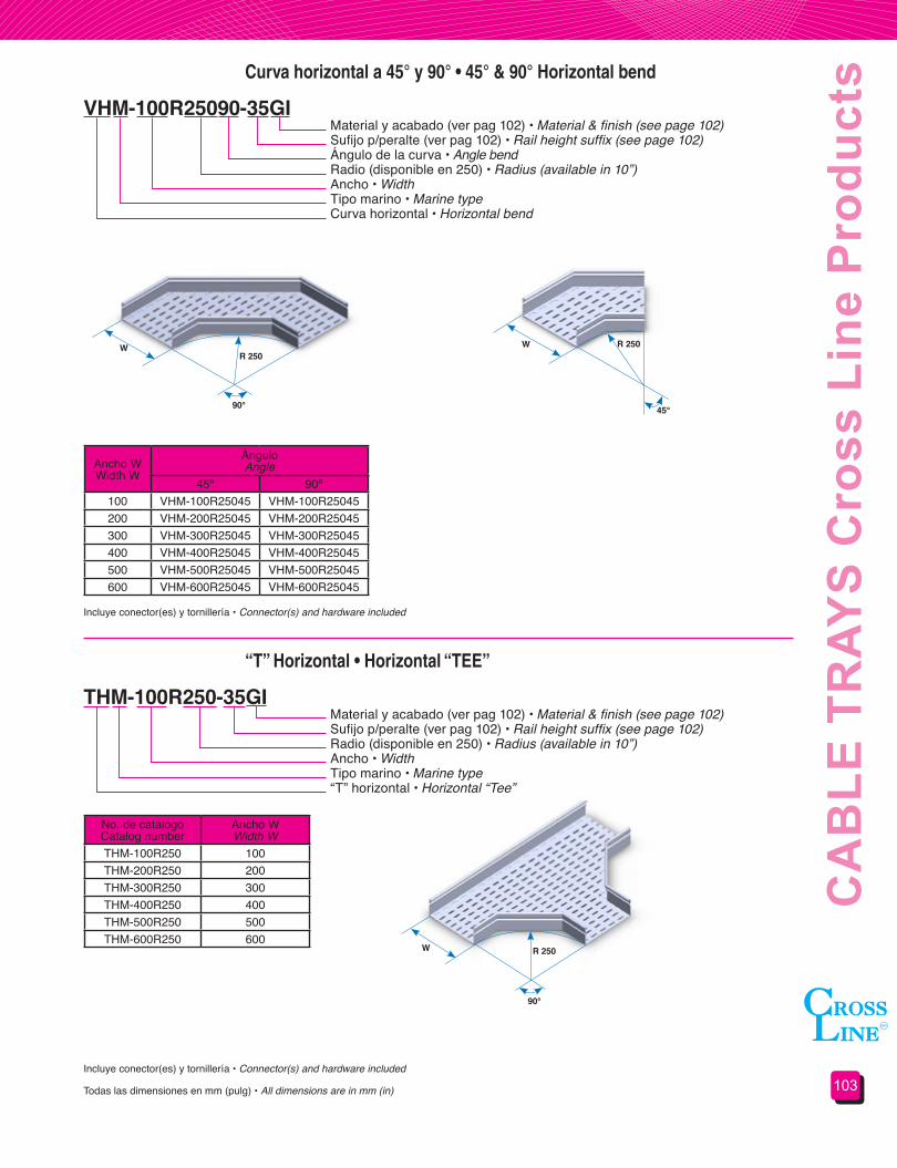
103
CA
BLE
TR
AYS
Cro
ss L
ine
Pro
duct
sCurva horizontal a 45° y 90° • 45° & 90° Horizontal bend
“T” Horizontal • Horizontal “TEE”
VHM-100R25090-35GI
THM-100R250-35GI
Material y acabado (ver pag 102) • Material & finish (see page 102)Sufijo p/peralte (ver pag 102) • Rail height suffix (see page 102)Ángulo de la curva • Angle bendRadio (disponible en 250) • Radius (available in 10”)Ancho • WidthTipo marino • Marine typeCurva horizontal • Horizontal bend
Material y acabado (ver pag 102) • Material & finish (see page 102)Sufijo p/peralte (ver pag 102) • Rail height suffix (see page 102)Radio (disponible en 250) • Radius (available in 10”)Ancho • WidthTipo marino • Marine type“T” horizontal • Horizontal “Tee”
Todas las dimensiones en mm (pulg) • All dimensions are in mm (in)
Incluye conector(es) y tornillería • Connector(s) and hardware included
Incluye conector(es) y tornillería • Connector(s) and hardware included
Ancho WWidth W
ÁnguloAngle
45º 90º100 VHM-100R25045 VHM-100R25045200 VHM-200R25045 VHM-200R25045300 VHM-300R25045 VHM-300R25045400 VHM-400R25045 VHM-400R25045500 VHM-500R25045 VHM-500R25045600 VHM-600R25045 VHM-600R25045
No. de catálogoCatalog number
Ancho WWidth W
THM-100R250 100 THM-200R250 200 THM-300R250 300THM-400R250 400THM-500R250 500THM-600R250 600
W WR 250
R 250
90° 45°
90°
W R 250
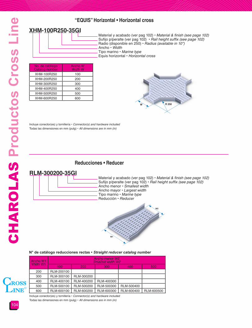
CH
AR
OLA
S P
rodu
ctos
Cro
ss L
ine
104
“EQUIS” Horizontal • Horizontal cross
Reducciones • Reducer
XHM-100R250-35GI
RLM-300200-35GI
Material y acabado (ver pag 102) • Material & finish (see page 102)Sufijo p/peralte (ver pag 102) • Rail height suffix (see page 102)Radio (disponible en 250) • Radius (available in 10”)Ancho • WidthTipo marino • Marine typeEquis horizontal • Horizontal cross
Material y acabado (ver pag 102) • Material & finish (see page 102)Sufijo p/peralte (ver pag 102) • Rail height suffix (see page 102)Ancho menor • Smallest widthAncho mayor • Largest widthTipo marino • Marine typeReducción • Reducer
Todas las dimensiones en mm (pulg) • All dimensions are in mm (in)Incluye conector(es) y tornillería • Connector(s) and hardware included
Incluye conector(es) y tornillería • Connector(s) and hardware includedTodas las dimensiones en mm (pulg) • All dimensions are in mm (in)
Ancho W1Width W1
Ancho menor W2 Smallest width W2
100 200 300 400 500200 RLM-200100300 RLM-300100 RLM-300200400 RLM-400100 RLM-400200 RLM-400300500 RLM-500100 RLM-500200 RLM-500300 RLM-500400600 RLM-600100 RLM-600200 RLM-600300 RLM-600400 RLM-600500
No. de catálogoCatalog number
Ancho WWidth W
XHM-100R250 100 XHM-200R250 200 XHM-300R250 300XHM-400R250 400XHM-500R250 500XHM-600R250 600
W R 250
W1
W2
N° de catálogo reducciones rectas • Straight reducer catalog number

105
CA
BLE
TR
AYS
Cro
ss L
ine
Pro
duct
sCurva vertical ajustable • Vertical adjustable bend
VAM-100R200-35GIMaterial y acabado (ver pag 102) • Material & finish (see page 102)Sufijo p/peralte (ver pag 102) • Rail height suffix (see page 102)Radio • RadiusAncho • WidthTipo marino • Marine typeCurva vertical ajustable • Vertical adjustable bend
RadioRadius
Elementos ajustablesAdjustable elements
200 1350 2500 3625 4
Cantidad de elementos ajustables • Adjustable element quantity
Ancho WWidth W
No. de catálogoCatalog Number
RadioRadius
200 350 500 625100 VAM-100R200 VAM-100R350 VAM-100R500 VAM-100R625200 VAM-200R200 VAM-200R350 VAM-200R500 VAM-200R625300 VAM-300R200 VAM-300R350 VAM-300R500 VAM-300R625400 VAM-400R200 VAM-400R350 VAM-400R500 VAM-400R625500 VAM-500R200 VAM-500R350 VAM-500R500 VAM-500R625600 VAM-600R200 VAM-600R350 VAM-600R500 VAM-600R625
Incluye 4 conectores EACM con tornillería • Four EACM connectors and hardware included
No incluye conectores ni tornillería • Connectors and hardware are not included
Todas las dimensiones en mm (pulg) • All dimensions are in mm (in) Incluye tornillería • Hardware included
No. de catálogoCatalog number
Ancho WWidth W
VAM-100R250 100 VAM-200R250 200 VAM-300R250 300VAM-400R250 400VAM-500R250 500VAM-600R250 600
Elemento vertical ajustable • Vertical adjustable element
Conector vertical ajustable • Vertical adjustable connector
VAM-10035GI
EACM-35GI
Material y acabado (ver pag 102) • Material & finish (see page 102)Sufijo p/peralte (ver pag 102) • Rail height suffix (see page 102)Ancho • WidthTipo marino • Marine typeElemento vertical ajustable • Vertical adjustable element
Material y acabado (ver pag 102) • Material & finish (see page 102)Sufijo p/peralte (ver pag 102) • Rail height suffix (see page 102)Tipo marino • Marine typeConector para curva vertical ajustable • Vertical adjustable bend connector

CH
AR
OLA
S P
rodu
ctos
Cro
ss L
ine
106
No requiere clips o tornillería • Clamps and hardware are not required
Incluye tornillería • Hardware included
Incluye tornillería • Hardware included
Tapa terminal • Blind end
Conectores • Connectors
PTRM-100-35GI
ARM-35GI
Material y acabado (ver pag 102) • Material & finish (see page 102)Sufijo p/peralte (ver pag 102) • Rail height suffix (see page 102)Ancho • WidthTipo marino • Marine typeTapa terminal • Blind end
Material y acabado (ver pag 102) • Material & finish (see page 102)Sufijo p/peralte (ver pag 102) • Rail height suffix (see page 102)Tipo marino • Marine typeConector tipo • Connector type
Todas las dimensiones en mm (pulg) • All dimensions are in mm (in)
Tapas • Covers
TCV THM-100R250-GIMaterial y acabado (ver pag 102) • Material & finish (see page 102)No de catálogo del producto a cubrir • Covered product catalog numberTapa con ceja y vena • Flanged and streaked cover
AR Tipo rectoSplice plate AR TYPE
AH Tipo horizontal ajustableHorizontal adjustable AH TYPE
EA Tipo vertical ajustableVertical adjustable EA TYPE
No. de catálogoCatalog number
Ancho WWidth W
PTRM-100 100 PTRM-200 200 PTRM-300 300PTRM-400 400PTRM-500 500PTRM-600 600
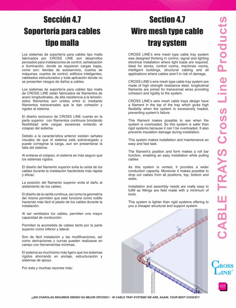
107
CA
BLE
TR
AYS
Cro
ss L
ine
Pro
duct
s
¡¡¡EN CHAROLAS SEGUIMOS SIENDO SU MEJOR OPCION!!! • IN CABLE TRAY SYSTEMS WE ARE, AGAIN, YOUR BEST CHOICE!!!
Los sistemas de soportería para cables tipo malla fabricados por CROSS LINE son desarrollos pensados para instalaciones de control, señalización e iluminación, donde se requieren cargas bajas, como son: tiendas de autoservicio, cuartos de máquinas, cuartos de control, edificios inteligentes, cableados estructurados y toda aplicación donde no se presenten riesgos de daños a cables.
Los sistemas de soportería para cables tipo malla de CROSS LINE están fabricados de filamentos de acero longitudinales, de alta resistencia a la tensión, estos filamentos son unidos entre sí mediante filamentos transversales que le dan cohesión y rigidez al sistema.
El diseño exclusivo de CROSS LINE cuenta en la parte superior con filamentos continuos brindando flexibilidad ante cargas excesivas evitando el colapso del sistema.
Debido a la característica anterior existen señales visuales de que el sistema está sobrecargado y puede corregirse la carga, aun sin presentarse la falla del sistema.
Al evitarse el colapso, el sistema es más seguro que los sistemas rígidos.
El diseño del filamento superior evita la caída de los cables durante la instalación haciéndola más rápida y eficaz.
La posición del filamento superior evita el daño al aislamiento de los cables.
El diseño de la varilla continua, así como la geometría del mismo permiten que este funcione como rodillo haciendo más fácil el jalado de los cables durante la instalación.
Al ser ventilados los cables, permiten una mayor capacidad de conducción.
Permiten la acometida de cables tanto por la parte superior como inferior y lateral.
Son de fácil instalación y las modificaciones, así como derivaciones y curvas pueden realizarse en campo con herramientas mínimas.
El sistema es muchísimo más ligero que los sistemas rígidos ahorrando en anclaje, estructuración y sistemas de apoyo.
Por esta y muchas razones más:
CROSS LINE’s wire mesh type cable tray system was designed thinking in control, signal and lighting electrical installation where light loads are required. Ideal for stores, control rooms, machines rooms, intelligent buildings, structural cabling and all applications where cables aren’t in risk of damage.
CROSS LINE’s wire mesh type cable tray system are made of high strength resistance steel, longitudinal filaments are joined for transversal wires providing cohesion and rigidity to the system.
CROSS LINE’s wire mesh cable trays design have a filament in the top of the tray which gives high flexibility when the system is excessively loaded, preventing system’s failure.
This filament makes possible to see when the system is overloaded. So this system is safer than rigid systems because it can´t be overloaded. It also prevents insulation damage during installation.
This system makes installation and maintenance an easy and fast task.
The filament’s position and form makes a roll bar function, enabling an easy installation while pulling cables
As this system is vented, it provides a wider conduction capacity. Moreover it makes possible to drop out cables from all positions, top, bottom and sides.
Installation and assembly needs are really easy to fulfill as fittings are field made with a minimum of tools.
This system is lighter than rigid systems offering to you a cheaper structural and support system.
Sección 4.7Soportería para cables
tipo malla
Section 4.7Wire mesh type cable
tray system
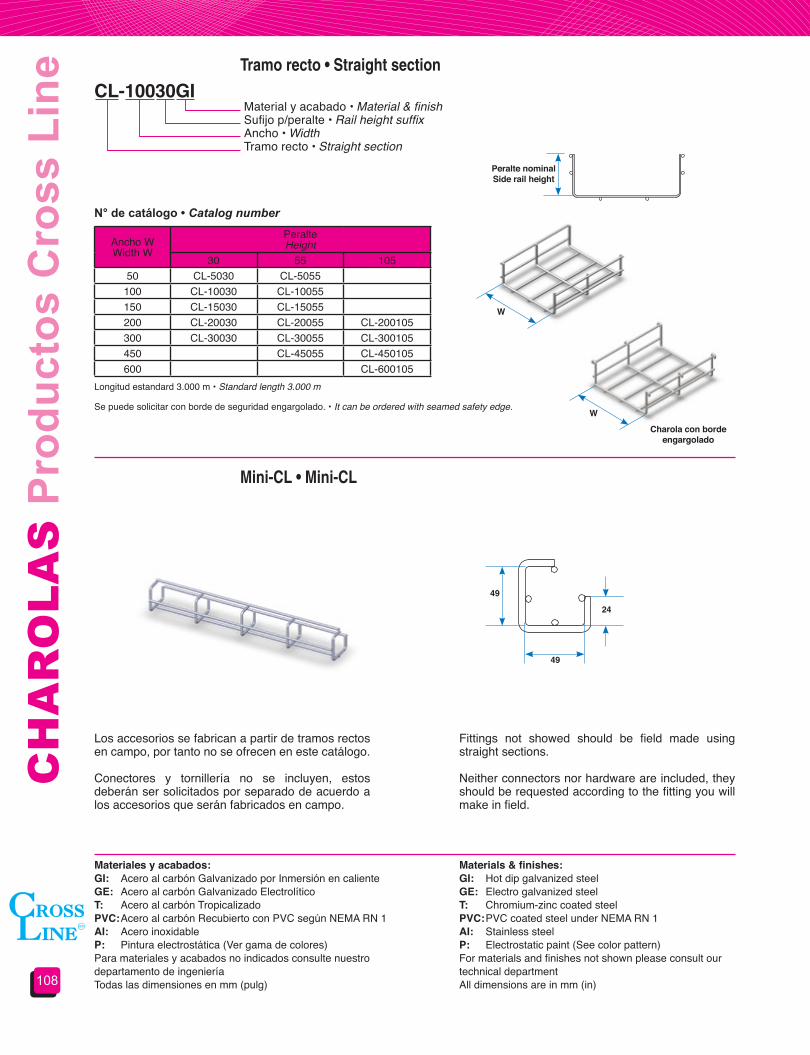
CH
AR
OLA
S P
rodu
ctos
Cro
ss L
ine
108
Los accesorios se fabrican a partir de tramos rectos en campo, por tanto no se ofrecen en este catálogo.
Conectores y tornillería no se incluyen, estos deberán ser solicitados por separado de acuerdo a los accesorios que serán fabricados en campo.
Fittings not showed should be field made using straight sections.
Neither connectors nor hardware are included, they should be requested according to the fitting you will make in field.
Tramo recto • Straight section
Mini-CL • Mini-CL
CL-10030GIMaterial y acabado • Material & finishSufijo p/peralte • Rail height suffixAncho • WidthTramo recto • Straight section
Ancho WWidth W
PeralteHeight
30 55 10550 CL-5030 CL-5055
100 CL-10030 CL-10055150 CL-15030 CL-15055200 CL-20030 CL-20055 CL-200105300 CL-30030 CL-30055 CL-300105450 CL-45055 CL-450105600 CL-600105
N° de catálogo • Catalog number
Longitud estandard 3.000 m • Standard length 3.000 m
Se puede solicitar con borde de seguridad engargolado. • It can be ordered with seamed safety edge.
W
W
Peralte nominalSiderailheight
49
49
24
Materiales y acabados:GI: Acero al carbón Galvanizado por Inmersión en caliente GE: Acero al carbón Galvanizado ElectrolíticoT: Acero al carbón TropicalizadoPVC: Acero al carbón Recubierto con PVC según NEMA RN 1AI: Acero inoxidableP: Pintura electrostática (Ver gama de colores)Para materiales y acabados no indicados consulte nuestro departamento de ingeniería Todas las dimensiones en mm (pulg)
Materials&finishes:GI: Hot dip galvanized steelGE: Electro galvanized steelT: Chromium-zinc coated steelPVC: PVC coated steel under NEMA RN 1AI: Stainless steelP: Electrostatic paint (See color pattern)For materials and finishes not shown please consult our technical departmentAll dimensions are in mm (in)
Charolaconbordeengargolado

109
CA
BLE
TR
AYS
Cro
ss L
ine
Pro
duct
sConectores universales • Standard connectors
Conector reforzado • Reinforced connector
Conector angular • Angle connector
CUCL-01
AEDT
AT 90
No. de catálogoCatalog number
Pieza 1Ditto 1
Pieza 2Ditto 2
CUCL-01 CE-25 CE-30
Cada conector incluye • Each connector includes
Los conectores pueden ser solicitados por juego (CUCL) o por partes (CE)Ambos conectores incluyen tornillería cuando son solicitados en juegoAl final del número de catálogo indicar material y acabado (ver página 108)
Connectors can be requested in kit (CUCL) or in parts (CE)Hardware included when they are requested in kitAt the end of the catalog number add material and finish (see page 108)
CUCL-01
No incluye conectores ni tornillería • Hardware and connectors are not included
No incluye conectores ni tornillería • Hardware and connectors are not included
Al final del número de catálogo indicar material y acabado (ver página 108) • At the end of the catalog number add material and finish (see page 108)
Al final del número de catálogo indicar material y acabado (ver página 108) • At the end of the catalog number add material and finish (see page 108)

CH
AR
OLA
S P
rodu
ctos
Cro
ss L
ine
110
Conectores rectos • Long splice plate
Conectores angular corto • Small angular connector
Clip colgante • Hanger clamp
AD 275AD 75
AD 250/90
AS
No incluye conectores ni tornillería • Hardware and connectors are not included
No incluye conectores ni tornillería • Hardware and connectors are not included
No incluye varilla • Rod not included
Al final del número de catálogo indicar material y acabado (ver página 108) • At the end of the catalog number add material and finish (see page 108)
Al final del número de catálogo indicar material y acabado (ver página 108) • At the end of the catalog number add material and finish (see page 108)
Al final del número de catálogo indicar material y acabado (ver página 108) • At the end of the catalog number add material and finish (see page 108)Todas las dimensiones en mm (pulg) • All dimensions are in mm (in)

111
CA
BLE
TR
AYS
Cro
ss L
ine
Pro
duct
s
Ancho charolaTray width
No. de catálogoCatalog number
50 SCCL-50100 SCCL-100150 SCCL-150200 SCCL-200300 SCCL-300450 SCCL-450600 SCCL-600
Ancho charolaTray width
No. de catálogoCatalog number
50 CRP-50100 CRP-100150 CRP-150200 CRP-200300 CRP-300450 CRP-450600 CRP-600
Ancho charolaTray width
No. de catálogoCatalog number
50 CS-50100 CS-100150 CS-150200 CS-200300 CS-300450 CS-450600 CS-600
Todas las dimensiones en mm (pulg) • All dimensions are in mm (in)No incluye tornillería, varillas, clips “U” ni sistemas de fijación • Hardware, “U” clamp, threaded rods or anchoring systems are not included.
Soporte colgante • Hanger support
Ménsula para pared • Wall cantilever bracket
Canal horizontal para trapecio • Horizontal channel for trapeze support
SCCL-100GI
CRP-100GI
CS-100GI
Material y acabado (ver pag 108) • Material & finish (see page 108)Ancho • WidthColgador • Hanger
Material y acabado (ver pag 108) • Material & finish (see page 108)Ancho • WidthMénsula para charola de malla • Wire mesh tray bracket
Material y acabado (ver pag 108) • Material & finish (see page 108)Ancho • WidthCanal horizontal charola de malla • Wire mesh tray horizontal channel
Clip “U”“U” Form clampVarilla roscada
Threadedrod

CH
AR
OLA
S P
rodu
ctos
Cro
ss L
ine
112
Longitud del canalChannel length
No. de catálogoCatalog number
150 UCSN-150200 UCSN-200300 UCSN-300400 UCSN-400500 UCSN-500600 UCSN-600
1000 UCSN-10002000 UCSN-20003000 UCSN-3000
No. de catálogoCatalog number
Longitud LLength L
MSNC-100 178MSNC-150 228MSNC-200 278MSNC-300 378MSNC-450 528MSNC-600 678
Todas las dimensiones en mm (pulg) • All dimensions are in mm (in)
No incluye tornillería, varillas, clips “U” ni sistemas de fijación • Hardware, “u” clamp, threaded rods or anchoring systems are not included
Canal universal • Universal channel
Ménsula de ensamble rápido • Fast assembly bracket
Soporte para piso • Floor support
UCSN-500GI
SPCL
MSNC
Material y acabado (ver pag 108) • Material & finish (see page 108)Longitud • LengthCanal universal • Universal channel
L
63
100
Clip “U”“U” Form clamp
Varilla roscadaThreadedrod
Al final del número de catálogo indicar material y acabado (ver página 108) • At the end of the catalog number add material and finish (see page 108)
Al final del número de catálogo indicar material y acabado (ver página 108) • At the end of the catalog number add material and finish (see page 108)
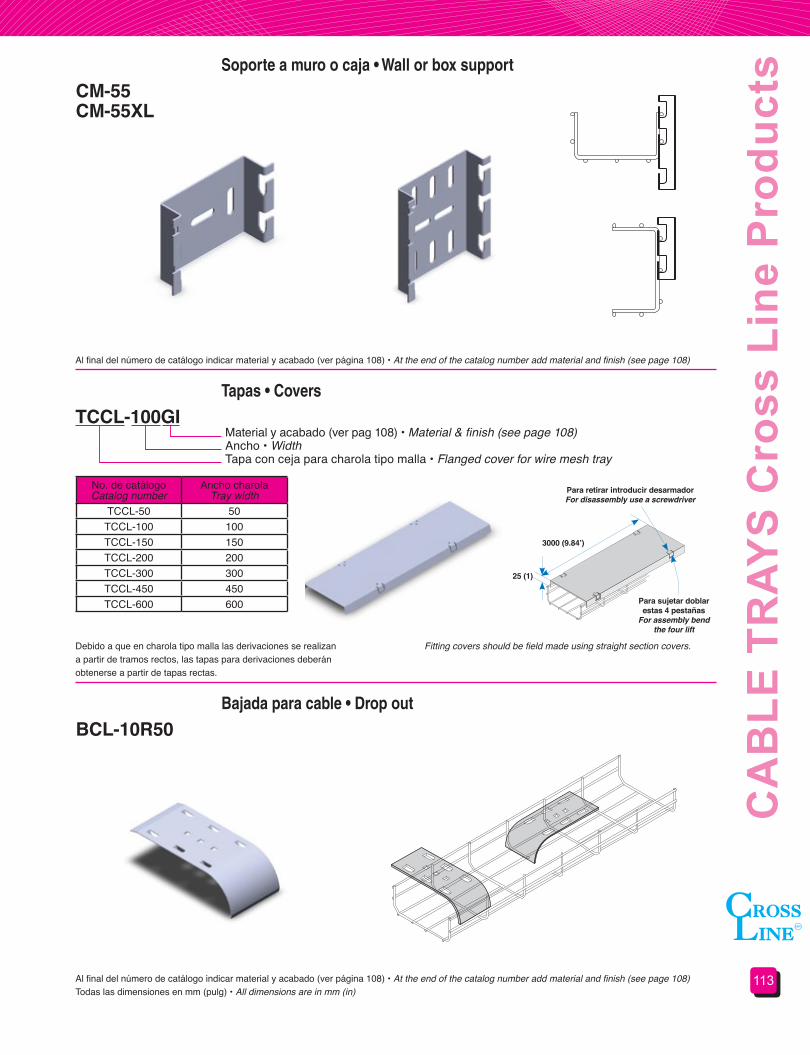
113
CA
BLE
TR
AYS
Cro
ss L
ine
Pro
duct
s
No. de catálogoCatalog number
Ancho charolaTray width
TCCL-50 50 TCCL-100 100 TCCL-150 150 TCCL-200 200 TCCL-300 300 TCCL-450 450 TCCL-600 600
Todas las dimensiones en mm (pulg) • All dimensions are in mm (in)
Soporte a muro o caja • Wall or box support
Tapas • Covers
Bajada para cable • Drop out
CM-55CM-55XL
TCCL-100GI
BCL-10R50
Material y acabado (ver pag 108) • Material & finish (see page 108)Ancho • WidthTapa con ceja para charola tipo malla • Flanged cover for wire mesh tray
Al final del número de catálogo indicar material y acabado (ver página 108) • At the end of the catalog number add material and finish (see page 108)
Al final del número de catálogo indicar material y acabado (ver página 108) • At the end of the catalog number add material and finish (see page 108)
Debido a que en charola tipo malla las derivaciones se realizan a partir de tramos rectos, las tapas para derivaciones deberán obtenerse a partir de tapas rectas.
Fitting covers should be field made using straight section covers.
3000(9.84’)
Para retirar introducir desarmadorFor disassembly use a screwdriver
Para sujetar doblar estas 4 pestañas
For assembly bend the four lift
25 (1)
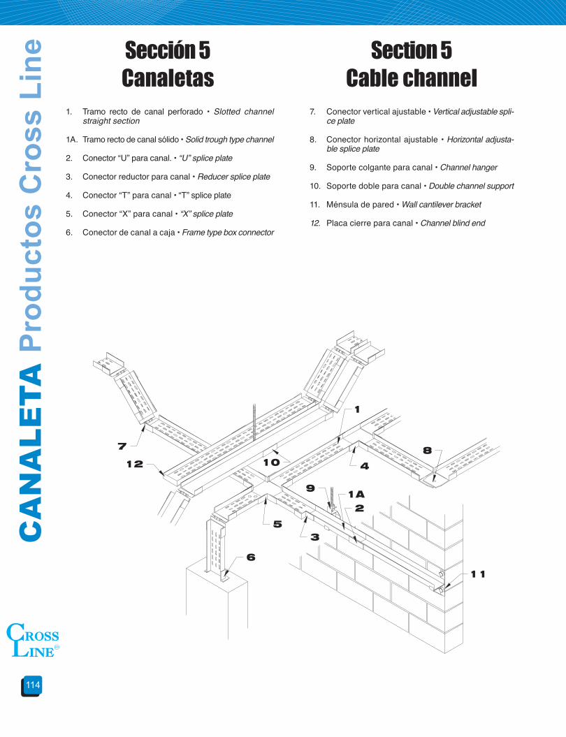
CA
NA
LETA
Pro
duct
os C
ross
Lin
e
114
1. Tramo recto de canal perforado • Slotted channel straight section
1A. Tramo recto de canal sólido • Solid trough type channel
2. Conector “U” para canal. • “U” splice plate
3. Conector reductor para canal • Reducer splice plate
4. Conector “T” para canal • “T” splice plate
5. Conector “X” para canal • “X” splice plate
6. Conector de canal a caja • Frame type box connector
7. Conector vertical ajustable • Vertical adjustable spli-ce plate
8. Conector horizontal ajustable • Horizontal adjusta-ble splice plate
9. Soporte colgante para canal • Channel hanger
10. Soporte doble para canal • Double channel support
11. Ménsula de pared • Wall cantilever bracket
12. Placa cierre para canal • Channel blind end
Sección 5 Canaletas
Section 5 Cable channel

115
CA
BLE
CH
AN
NE
L C
ross
Lin
e Pr
oduc
tsTramo recto • Straight section
Conector “U” • “U” Splice plate
CHSV-4152 32A
AUCV-3 A
Material y acabado • Material & finishPeralte en mm • Depth in mmLongitud en cm • Length in cmAncho en pulgadas • Width in inchesTipo de fondo • Trough typeTramo recto • Straight section
Material y acabado • Material & finishAncho en pulgadas • Width in inchesPara canaleta • For cable channelConector “U” • “U” splice plate
Ancho WWidth W
Fondo perforadoSlotted Trough
Fondo lisoSolid Trough
Longitud • Length Longitud • Length1524 (60) 3048 (120) 1524 (60) 3048 (120)
76 (3) CHCV-3152 CHCV-3305 CHSV-3152 CHSV-3305102 (4) CHCV-4152 CHCV-4305 CHSV-4152 CHSV-4305152 (6) CHCV-6152 CHCV-6305 CHSV-6152 CHSV-6305
N° de catálogo • Catalog number
Incluye conector y tornillería • Connector and hardware included
Incluye tornillería • Hardware included
Materiales y acabados:A: Aluminio aleación AA-3003 acabado naturalGI: Acero al carbón galvanizado por inmersión en calienteGE: Acero al carbón galvanizado electrolíticoT: Acero al carbón tropicalizadoPVC: Acero al carbón recubierto con PVC según NEMA RN 1PVA: Aluminio recubierto con PVC según NEMA RN 1 AI: Acero inoxidablePara materiales y acabados no indicados consulte nuestro departamento de ingeniería.Todas las dimensiones en mm (pulg).
Materials&finishes:A: AA-3003 natural finished aluminumGI: Hot dip galvanized steelGE: Electro galvanized steelT: Chromium-zinc coated steelPVC: PVC coated steel under NEMA RN 1PVA: PVC coated aluminum under NEMA RN 1AI: Stainless steelFor materials and finishes not shown please consult our technical department.All dimensions are in mm (in).
Ancho WWidth W
PeralteDepth
76 (3) 32 mm ( 1 1/4”)
102 (4)32 mm ( 1 1/4”)44 mm ( 1 3/4”)
152 (6) 44 mm ( 1 3/4”)
No. de catálogoCatalog number
Ancho WWidth W
AUCV-3 76 (3)AUCV-4 102 (4)AUCV-6 152 (6)
W
W

CA
NA
LETA
Pro
duct
os C
ross
Lin
e
116
Conector “T” • “T” Splice plate
Conector “X” • “X” Splice plate
Conector reductor • Reducer splice plate
ATCV-3 A
AXCV-3 A
ARCV-63 A
Material y acabado (ver pág. 115) • Material & finish (see page 115)Ancho en pulgadas • Width in inchesPara canaleta • For cable channelConector “T” • “T” splice plate
Material y acabado (ver pág. 115) • Material & finish (see page 115)Ancho en pulgadas • Width in inchesPara canaleta • For cable channelConector “X” • “X” splice plate
Material y acabado (ver pág. 115) • Material & finish (see page 115)Ancho menor en pulg. • Smallest width in inchesAncho mayor en pulg. • Largest width in inchesPara canaleta • For cable channelConector reductor • Reducer splice plate
Incluye tornillería • Hardware included
Incluye tornillería • Hardware included
Incluye tornillería • Hardware includedTodas las dimensiones en mm (pulg) • All dimensions are in mm (in)
No. de catálogoCatalog number
Ancho WWidth W
ATCV-3 76 (3)ATCV-4 102 (4)ATCV-6 152 (6)
No. de catálogoCatalog number
Ancho WWidth W
AXCV-3 76 (3)AXCV-4 102 (4)AXCV-6 152 (6)
Ancho W1Width W1
Ancho W2Width W2
76 (3) 102 (4)102 (4) ARCV-43152 (6) ARCV-63 ARCV-64
N° de catálogo • Catalog number
Conector vertical ajustable • Vertical adjustable splice plate
AVACV-3 AMaterial y acabado (ver pág. 115) • Material & finish (see page 115)Ancho en pulgadas • Width in inchesPara canaleta • For cable channel Conector vertical ajustable • Vertical adjustable splice plate
Incluye tornillería • Hardware included
No. de catálogoCatalog number
Ancho WWidth W
AVACV-3 76 (3)AVACV-4 102 (4)AVACV-6 152 (6)
W1
W2
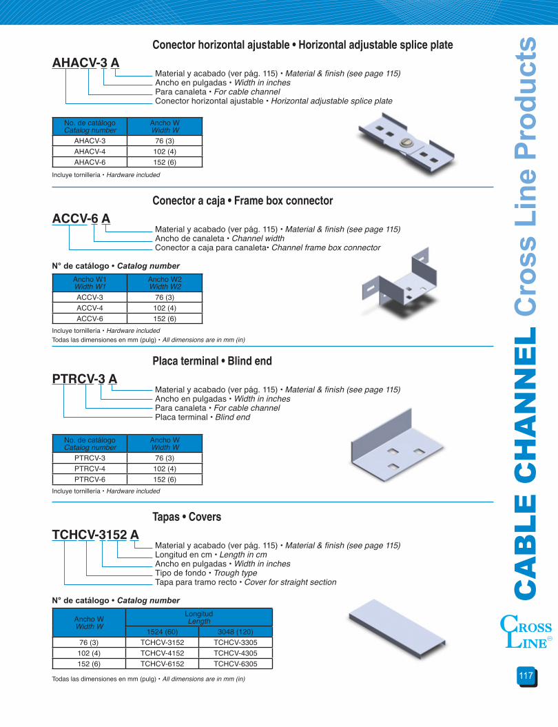
117
CA
BLE
CH
AN
NE
L C
ross
Lin
e Pr
oduc
ts
Placa terminal • Blind end
Conector horizontal ajustable • Horizontal adjustable splice plate
Tapas • Covers
Conector a caja • Frame box connector
PTRCV-3 A
AHACV-3 A
TCHCV-3152 A
ACCV-6 A
Material y acabado (ver pág. 115) • Material & finish (see page 115)Ancho en pulgadas • Width in inchesPara canaleta • For cable channel Placa terminal • Blind end
Material y acabado (ver pág. 115) • Material & finish (see page 115)Ancho en pulgadas • Width in inchesPara canaleta • For cable channelConector horizontal ajustable • Horizontal adjustable splice plate
Material y acabado (ver pág. 115) • Material & finish (see page 115)Longitud en cm • Length in cmAncho en pulgadas • Width in inchesTipo de fondo • Trough typeTapa para tramo recto • Cover for straight section
Material y acabado (ver pág. 115) • Material & finish (see page 115)Ancho de canaleta • Channel widthConector a caja para canaleta• Channel frame box connector
Incluye tornillería • Hardware included
Incluye tornillería • Hardware included
Incluye tornillería • Hardware includedTodas las dimensiones en mm (pulg) • All dimensions are in mm (in)
Todas las dimensiones en mm (pulg) • All dimensions are in mm (in)
No. de catálogoCatalog number
Ancho WWidth W
PTRCV-3 76 (3)PTRCV-4 102 (4)PTRCV-6 152 (6)
No. de catálogoCatalog number
Ancho WWidth W
AHACV-3 76 (3)AHACV-4 102 (4)AHACV-6 152 (6)
Ancho WWidth W
LongitudLength
1524 (60) 3048 (120)76 (3) TCHCV-3152 TCHCV-3305
102 (4) TCHCV-4152 TCHCV-4305152 (6) TCHCV-6152 TCHCV-6305
Ancho W1Width W1
Ancho W2Width W2
ACCV-3 76 (3)ACCV-4 102 (4)ACCV-6 152 (6)
N° de catálogo • Catalog number
N° de catálogo • Catalog number

CA
NA
LETA
Pro
duct
os C
ross
Lin
e
118
Ménsula para pared • Wall cantilever bracket
Soporte doble • Double hanger support
Soporte colgante • Hanger support
Clip de sujeción para tapa • Cover clamp
MPCV-3GI
SDCV-3GI
SCCV-3GI
CSTCV-14GI
Material y acabado (ver pág. 115 excepto aluminio) • Material & finish (see page 115 except aluminum)Ancho en pulgadas • Width in inchesPara canaleta • For cable channel Ménsula para pared • Wall cantilever bracket
Material y acabado (ver pág. 115 excepto aluminio) • Material & finish (see page 115 except aluminum)Ancho en pulgadas • Width in inchesPara canaleta • For cable channel Soporte doble • Double support
Material y acabado (ver pág. 113 excepto aluminio) • Material & finish (see page 113 except aluminum)Ancho en pulgadas • Width in inchesPara canaleta • For cable channel Soporte colgante • Hanger support
Material y acabado (ver pág. 115) • Material & finish (see page 115)Clip de sujeción para tapa • Cover clamp
Incluye tornillería • Hardware included
Todas las dimensiones en mm (pulg) • All dimensions are in mm (in)
No. de catálogoCatalog number
Ancho WWidth W
MPCV-3 76 (3)MPCV-4 102 (4)MPCV-6 152 (6)
No. de catálogoCatalog number
Ancho WWidth W
SDCV-3 76 (3)SDCV-4 102 (4)SDCV-6 152 (6)
No. de catálogoCatalog number
Ancho WWidth W
SCCV-3 76 (3)SCCV-4 102 (4)SCCV-6 152 (6)
W
W
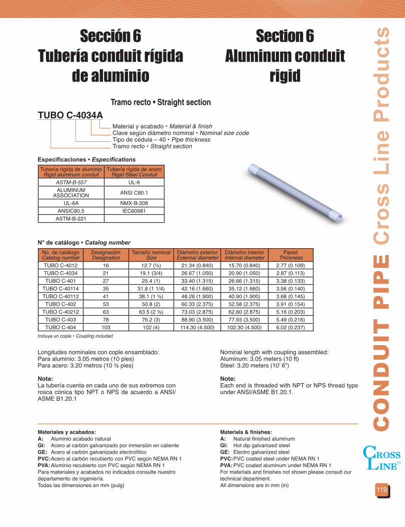
119
CO
ND
UIT
PIP
E C
ross
Lin
e P
rodu
cts
TUBO C-4034A
Sección 6Tubería conduit rígida
de aluminio
Section 6Aluminum conduit
rigidTramo recto • Straight section
Material y acabado • Material & finishClave según diámetro nominal • Nominal size codeTipo de cédula – 40 • Pipe thicknessTramo recto • Straight section
Tubería rígida de aluminioRigid aluminum conduit
Tubería rígida de aceroRigid Steel Conduit
ASTM-B-557 UL-6ALUMINUM
ASSOCIATION ANSI C80.1
UL-6A NMX-B-208ANSIC80.5 IEC60981
ASTM-B-221
No. de catálogoCatalog number
DesignaciónDesignation
Tamaño nominalSize
Diámetro exteriorExternal diameter
Diámetro interiorInternal diameter
ParedThickness
TUBO C-4012 16 12.7 (½) 21.34 (0.840) 15.70 (0.840) 2.77 (0.109)TUBO C-4034 21 19.1 (3/4) 26.67 (1.050) 20.90 (1.050) 2.87 (0.113)TUBO C-401 27 25.4 (1) 33.40 (1.315) 26.66 (1.315) 3.38 (0.133)
TUBO C-40114 35 31.8 (1 1/4) 42.16 (1.660) 35.12 (1.660) 3.56 (0.140)TUBO C-40112 41 38.1 (1 ½) 48.26 (1.900) 40.90 (1.900) 3.68 (0.145)TUBO C-402 53 50.8 (2) 60.33 (2.375) 52.58 (2.375) 3.91 (0.154)
TUBO C-40212 63 63.5 (2 ½) 73.03 (2.875) 62.60 (2.875) 5.16 (0.203)TUBO C-403 78 76.2 (3) 88.90 (3.500) 77.93 (3.500) 5.49 (0.216)TUBO C-404 103 102 (4) 114.30 (4.500) 102.30 (4.500) 6.02 (0.237)
Especificaciones • Especifications
N° de catálogo • Catalog number
Longitudes nominales con cople ensamblado:Para aluminio: 3.05 metros (10 pies)Para acero: 3.20 metros (10 ½ pies)
Nota:La tubería cuenta en cada uno de sus extremos con rosca cónica tipo NPT o NPS de acuerdo a ANSI/ASME B1.20.1
Nominal length with coupling assembled:Aluminum: 3.05 meters (10 ft)Steel: 3.20 meters (10’ 6”)
Note:Each end is threaded with NPT or NPS thread type under ANSI/ASME B1.20.1.
Materiales y acabados:A: Aluminio acabado naturalGI: Acero al carbón galvanizado por inmersión en calienteGE: Acero al carbón galvanizado electrolíticoPVC: Acero al carbón recubierto con PVC según NEMA RN 1PVA: Aluminio recubierto con PVC según NEMA RN 1Para materiales y acabados no indicados consulte nuestro departamento de ingeniería.Todas las dimensiones en mm (pulg)
Materials&finishes:A: Natural finished aluminumGI: Hot dip galvanized steelGE: Electro galvanized steelPVC: PVC coated steel under NEMA RN 1PVA: PVC coated aluminum under NEMA RN 1For materials and finishes not shown please consult our technical department.All dimensions are in mm (in)
Incluye un cople • Coupling included
FALTA IMAGEN

TU
BE
RÍA
Pro
duct
os C
ross
Lin
e
120
Codo conduit a 90° • 90° Conduit elbow
Coples conduit • Conduit coupling
CODO90-12A
COPLE-12A
Material y acabado (ver pág. 119) • Material & finish (see page 119)Clave según diámetro nominal • Nominal size codeCodo conduit a 90°• 90° Conduit elbow
Material y acabado (ver pág. 119) • Material & finish (see page 119)Clave según diámetro nominal • Nominal size codeCople conduit • Conduit coupling
Tubería rígida de aluminioRigid aluminum conduit
Tubería rígida de aceroRigid steel conduit
ALUMINUM ASSOCIATION UL-6,
UL-6A ANSI C80.1, ANSIC80.5
No. de catálogoCatalog number
Tamaño nominalSize
Diámetro exteriorExternal diameter
ParedThickness
COPLE-12 12.7 (½) 27.4 (1.08) 49.2 (1.94)COPLE-34 19.1 (3/4) 33.7 (1.33) 41.3 (1.62)COPLE-1 25.4 (1) 39.7 (1.56) 50.8 (2.00)
COPLE-114 31.8 (1 1/4) 49.6 (1.95) 52.4 (2.06)COPLE-112 38.1 (1 ½) 56.3 (2.22) 52.4 (2.06)COPLE-2 50.8 (2) 69.8 (2.75) 54.0 (2.12)
COPLE-212 63.5 (2 ½) 83.3 (3.28) 79.4 (3.12)COPLE-3 76.2 (3) 100 (3.94) 82.5 (3.25)COPLE-4 102 (4) 127 (5.00) 88.9 (3.50)
No. de catálogoCatalog number
Tamaño nominalSize
Radio al eje neutroNeutral axis radius
CODO90-12 12.7 (½) 101.6 (4.00)CODO90-34 19.1 (3/4) 114.3 (4.50)CODO90-1 25.4 (1) 146.1 (5.75)
CODO90-114 31.8 (1 1/4) 184.2 (7.25)CODO90-112 38.1 (1 ½) 209.6 (8.25)CODO90-2 50.8 (2) 241.3 (9.50)
CODO90-212 63.5 (2 ½) 266.7 (10.50)CODO90-3 76.2 (3) 330.2 (13.00)CODO90-4 102 (4) 508.0 (20.00)
Especificaciones • Especifications
Nota:La tubería cuenta en cada uno de sus extremos con rosca cónica tipo NPT o NPS de acuerdo a ANSI/ASME B1.20.1
Cuenta en cada uno de sus extremos con rosca cónica tipo NPT o NPS de acuerdo a ANSI/ASME B1.20.1
Note:Each end is threaded with NPT or NPS thread type under ANSI/ASME B1.20.1
Threaded with NPT or NPS thread type under ANSI/ASME B1.20.1
No incluye cople • Coupling not included
Todas las dimensiones en mm (pulg) • All dimensions are in mm (in)
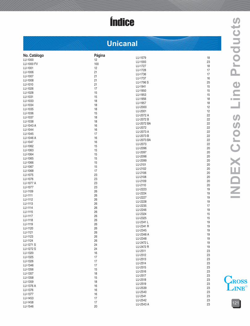
121
IND
EX C
ross
Lin
e P
rodu
ctsÍndice
UnicanalNo. Catálogo PáginaLU-1000 12LU-1000 FV 100LU-1001 12LU-1006 21LU-1007 21LU-1008 21LU-1010 21LU-1026 17LU-1028 15LU-1031 15LU-1033 18LU-1034 18LU-1035 18LU-1036 15LU-1037 18LU-1038 18LU-1043 A 16LU-1044 16LU-1045 17LU-1046 A 16LU-1047 16LU-1062 15LU-1063 15LU-1064 15LU-1065 15LU-1066 15LU-1067 15LU-1068 17LU-1075 23LU-1076 23LU-1077 A 23LU-1077 23LU-1109 26LU-1111 26LU-1112 26LU-1113 26LU-1114 26LU-1115 26LU-1117 26LU-1118 26LU-1119 26LU-1120 26LU-1121 26LU-1123 26LU-1124 26LU-1271 S 24LU-1272 S 24LU-1320 16LU-1325 17LU-1326 17LU-1346 17LU-1356 15LU-1357 18LU-1358 15LU-1359 18LU-1376 A 16LU-1376 16LU-1377 16LU-1453 17LU-1458 17LU-1546 20
LU-1579 18LU-1593 23LU-1727 18LU-1728 17LU-1736 17LU-1737 16LU-1796 S 25LU-1941 15LU-1950 15LU-1953 15LU-1956 18LU-1957 18LU-2000 12LU-2001 12LU-2072 A 22LU-2072 B 22LU-2072 BA 22LU-2072 22LU-2073 A 22LU-2073 B 22LU-2073 BA 22LU-2073 22LU-2096 20LU-2097 20LU-2098 20LU-2099 20LU-2101 20LU-2102 20LU-2106 20LU-2108 20LU-2109 20LU-2110 20LU-2223 19LU-2224 19LU-2227 19LU-2228 19LU-2235 17LU-2246 19LU-2324 15LU-2325 15LU-2341 L 19LU-2341 R 19LU-2345 19LU-2348 A 19LU-2348 19LU-2472 L 19LU-2472 R 19LU-2511 23LU-2512 23LU-2513 23LU-2514 23LU-2515 23LU-2516 23LU-2517 23LU-2518 23LU-2519 23LU-2539 23LU-2540 23LU-2541 23LU-2542 23LU-2543 A 23

ÍND
ICE
Prod
ucto
s C
ross
Lin
e
122
ÍndiceLU-2544 A 23LU-2545 A 23LU-2546 A 23LU-2676 24LU-2785 25LU-2867 25LU-2868 25LU-3006 21LU-3007 21LU-3008 21LU-3010 21LU-3184 P 14LU-3265 14
LU-3300 12LU-3300 FV 99LU-3301 12LU-3345 17LU-3347 16LU-4000 12LU-4001 12LU-5500 13LU-5501 13LU-6000 13LU-7000 13PRLU 13PSLU 13
Abrazaderas
Ductos
No. Catálogo páginaACCTM 51ACO 50ACTM 51
AP 51AU120 52AU137 52AUM 52
No. Catálogo páginaADTP 37ARDTP 37DA 33DBC 43DBE 45DBPTR 45DBR 43DBRR 45DBT 44DBTV 44DBV 44DBX 44DC 90 31DC 45 32DCG 31DCGAE 39DCHAE 90 39DCHAE 45 40DCIHAE 90 40DCIHAE 45 40DCVAE 90 40DCVAE 45 41DH 33DHBR 45DM 33DR 31
DRAE 39DRLTP 36DRR 32DT 32DTC 33DTHAE 41DTHTP 36DTP 35DTP-CLIP 37DTP-FC 37DTVAE 41DTVTP 37DVCC 90 47DVCC 45 48DVCG 47DVCR 47DVCTH 48DVCTV 49DVCVE 90 48DVCVE 45 49DVCVI 90 49DVCVI 45 49DVCXH 48DVETP 37DVHTP 35DVITP 36DX 32DXHTP 36TTDTP 37
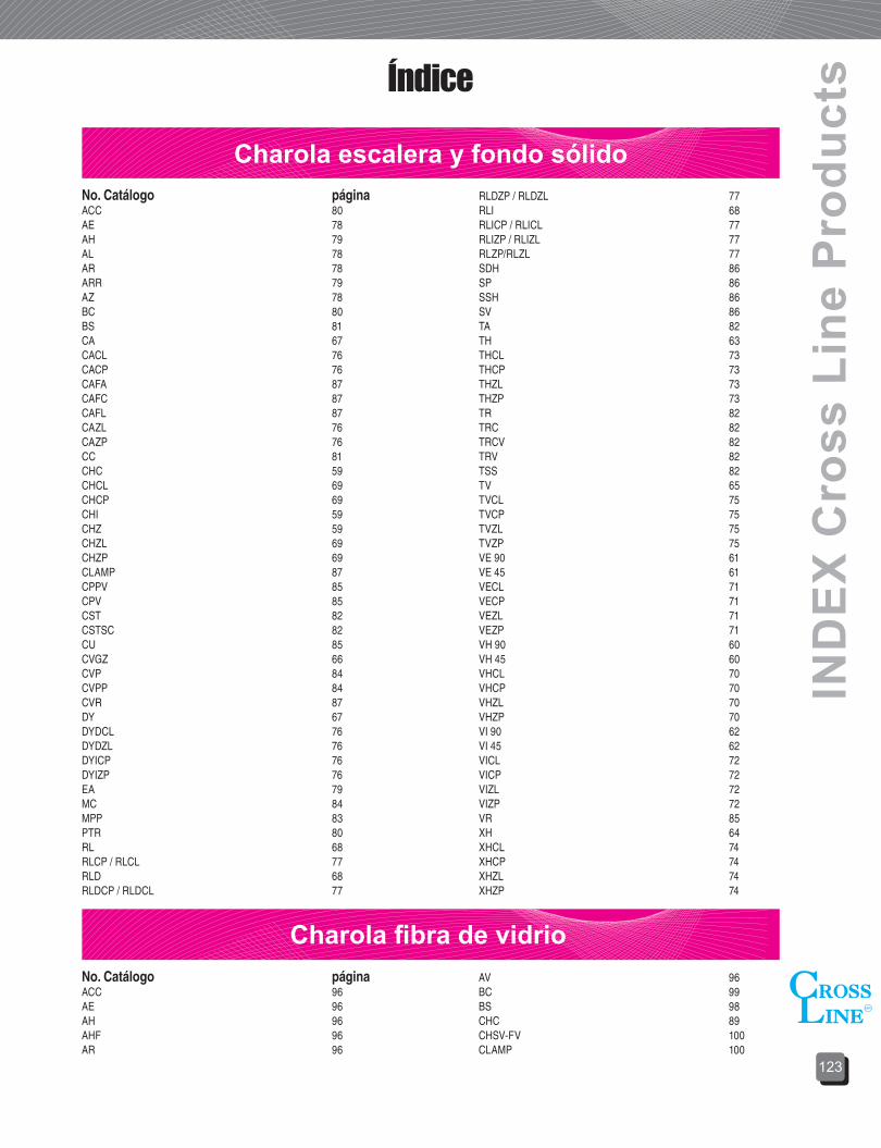
123
IND
EX C
ross
Lin
e P
rodu
ctsÍndice
Charola escalera y fondo sólidoNo. Catálogo páginaACC 80AE 78AH 79AL 78AR 78ARR 79AZ 78BC 80BS 81CA 67CACL 76CACP 76CAFA 87CAFC 87CAFL 87CAZL 76CAZP 76CC 81CHC 59CHCL 69CHCP 69CHI 59CHZ 59CHZL 69CHZP 69CLAMP 87CPPV 85CPV 85CST 82CSTSC 82CU 85CVGZ 66CVP 84CVPP 84CVR 87DY 67DYDCL 76DYDZL 76DYICP 76DYIZP 76EA 79MC 84MPP 83PTR 80RL 68RLCP / RLCL 77RLD 68RLDCP / RLDCL 77
RLDZP / RLDZL 77RLI 68RLICP / RLICL 77RLIZP / RLIZL 77RLZP/RLZL 77SDH 86SP 86SSH 86SV 86TA 82TH 63THCL 73THCP 73THZL 73THZP 73TR 82TRC 82TRCV 82TRV 82TSS 82TV 65TVCL 75TVCP 75TVZL 75TVZP 75VE 90 61VE 45 61VECL 71VECP 71VEZL 71VEZP 71VH 90 60VH 45 60VHCL 70VHCP 70VHZL 70VHZP 70VI 90 62VI 45 62VICL 72VICP 72VIZL 72VIZP 72VR 85XH 64XHCL 74XHCP 74XHZL 74XHZP 74
Charola fibra de vidrioNo. Catálogo páginaACC 96AE 96AH 96AHF 96AR 96
AV 96BC 99BS 98CHC 89CHSV-FV 100CLAMP 100

ÍND
ICE
Prod
ucto
s C
ross
Lin
e
124
Índice
CanaletaNo. Catálogo páginaACCV 117AHACV 117ARCV 116ATCV 116AUCV 113AVACV 116AXCV 116
CHCV 115CHSV 115CSTCV 118MPCV 118PTRCV 117SCCV 118SDCV 118TCHCV 117
Tubo conduitNo. Catálogo páginaTUBO 119CODO90 120COPLE 120
Charolas tipo marino No. Catálogo páginaAHM 106ARM 106CHM 102EACM 105EAM 106
PTRM 106RLM 104TCV 106THM 103VAM 105VHM 103XHM 104
Soporte tipo mallaNo. Catálogo páginaAD 250 / 90 110AD 275 110AD 75 110AEDT 109AS 110AT90 109BCL 113CL 108
CM 113CRP 111CS 111CUCL 109MINI CL 108MSNC 112SCCL 111SPCL 112TCCL 113UCSN 112
CLAMP-FV 100CLAMPGUIA-FV 100CPV-FV 101EA 96MPP-FV 101PTR 97RLC 94RLDC 94RLIC 94
TA 98THC 93TR 97TRV 97TVC 95VAC 95VEC 91VHC 90VIC 92XHC 93


DU
CT
O
CH
AR
OL
AS
AB
RA
ZA
DE
RA
S
CA
NA
LE
TA
TU
BE
RÍA
UN
ICA
NA
L
S U C U R S A L E S
Cat
álog
o G
ener
al
201
3G
ener
al C
atal
og
2013Fabricantes de soportes y ductos
para instalaciones electricas
MÉXICO (CUAUTITLAN IZCALLI)Calle Alessandro Volta Lote. 1 y 2.
Parque Industrial CuamatlaCuautitlan Izcalli Estado de México.
C.P. 54730TEL: 01 (55) 58-70-11-97
Lada Sin Costo 01800-CROSS LINE 27677 5463
MÉXICO (CENTRO)Revillagigedo 36-A Col. Centro
C.P. 06050 México, DF.TEL: 01 (55) 55-21-68-31
55-21-68-51 53-86-46-54
FAX: 01 (55) 55-21-71-20
ESTADO DE MÉXICO.Calle Manzanillo No. 807
Col. San Jerónimo ChicahualcoMetepec Edo. Méx. C.P, 52170
TEL: 01 (722) 275-08-43 180-19-57
Juncos No.104 Col. Villa de las FloresCoacalco, Edo. Méx. C.P. 55710
TEL: 01 (55) 58-75-77-19FAX: 01 (55) 59-05-21-47
QUERÉTARO, QUERÉTAROAv. Del Bambú No. 13
Col. El Carrizal Santiago de QuerétaroC.P. 76030
TEL: 01 (442) 242-40-37 242-10-01
MONTERREY, NUEVO LEÓNPriv. Ernesto García Ortiz No. 60
Col. Del Norte, C.P. 64500TEL: 01 (81) 83-51-87-31
Lada Sin Costo 01 800-713-93-75 713-09-06
CIUDAD MADERO, TAMAULIPASTEL: 01 (833) 210-57-96
GUADALAJARA, JALCalle 2 No. 2345
Zona Industrial C.P. 44940TEL: 01 (33) 38-10-25-00
38-10-25-05
TIJUANA, B.C.Calle Abasolo No. 7970Col. Mérida C.P. 22660
Tijuana Baja California N.TEL: 01 (664) 689-81-54
629-14-77
SAN LUIS POTOSÍAv. Tecnológico No. 108-A
Col. 21 de Marzo S.L.P. C.P. 78437
TEL: 01 (444) 822-51-08
Av. Salvador Nava Martínez No.704-BCol. Nuevo Paseo S.L.P C.P.78328
TEL: 01 (444) 841-59-71
LEÓN GUANAJUATOBlvd. Juan José Torres Landa No. 6101
Col. San Isidro C.P. 37510León, Gto.
TEL: 01 (477) 771-88-40
HERMOSILLO, SONORACalle Simón Bley No. 8 entreC/Nayarit y C/Aguascalientes
Col. Olivares C.P. 83180TEL: 01 (662) 260-70-90
260-70-94
Calle Manuel I. Loaiza No.162Col. Olivares, Hillo. C.P. 83180
TEL: 01 (662) 216-16-36
Calle Félix Soria No.33ACol. San Benito, Hillo. C.P. 83190
TEL: 01 (662) 267-04-45
PUEBLA, PUEBLAVictoria No.31 Col. Sanctorum C.P.72100
TEL: 01 (222) 187-72-67 210-58-78
MÉRIDA, YUCATÁNAv. Yucatán No. 801 Col. Jardines
de Mérida Yucatán C.P. 97135TEL: 01 (999) 155-80-40
CULIACÁN, SINALOAAv. Ejército Nacional No.2897
Col. Emiliano Zapata C.P. 80260TEL: 01 (667) 727-04-29
718-30-66