CORTATUBOS BISELADOR ELÉCTRICO / ELECTRIC … · Si utiliza el motor hidráulico, compruebe la...
26
MANUAL DE INSTRUCCIONES OPERATING INSTRUCTIONS CORTATUBOS BISELADOR ELÉCTRICO / ELECTRIC CUTTING AND BEVELLING MACHINE ESPAÑOL ............................... 2 ENGLISH .............................. 12 GARANTIA / GUARANTEE... 23 COD. 55815 COD. 55824 COD. 55816 COD. 55825 COD. 55817 COD. 55826 COD. 55818 COD. 55827 COD. 55819 COD. 55828 COD. 55820 COD. 55829 COD. 55821 COD. 55830 COD. 55822 COD. 55831 COD. 55823 COD. 55832
Transcript of CORTATUBOS BISELADOR ELÉCTRICO / ELECTRIC … · Si utiliza el motor hidráulico, compruebe la...

MANUAL DE INSTRUCCIONESOPERATING INSTRUCTIONS
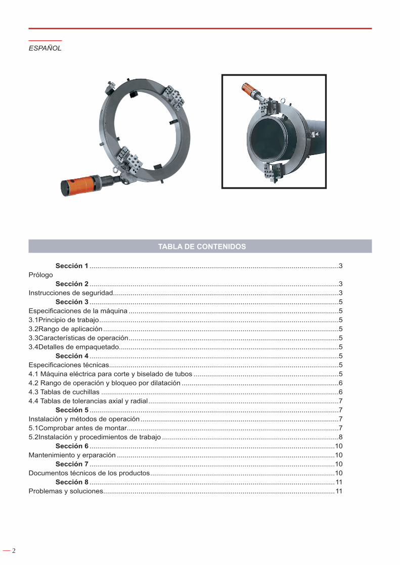
CORTATUBOS BISELADOR ELÉCTRICO / ELECTRIC CUTTING
AND BEVELLING MACHINE
ESPAÑOL ............................... 2
ENGLISH .............................. 12
GARANTIA / GUARANTEE ... 23
COD. 55815COD. 55824COD. 55816COD. 55825COD. 55817COD. 55826COD. 55818COD. 55827COD. 55819COD. 55828COD. 55820COD. 55829COD. 55821COD. 55830COD. 55822COD. 55831COD. 55823COD. 55832
2
TABLA DE CONTENIDOS
Sección 1 ...............................................................................................................................3Prólogo Sección 2 ...............................................................................................................................3Instrucciones de seguridad...................................................................................................................3 Sección 3 ...............................................................................................................................5Especificaciones de la máquina ...........................................................................................................53.1 Principio de trabajo ..........................................................................................................................53.2 Rango de aplicación ........................................................................................................................53.3 Características de operación ...........................................................................................................53.4 Detalles de empaquetado................................................................................................................5 Sección 4 ...............................................................................................................................5Especificaciones técnicas.....................................................................................................................54.1 Máquina eléctrica para corte y biselado de tubos ..........................................................................54.2 Rango de operación y bloqueo por dilatación ................................................................................64.3 Tablas de cuchillas .........................................................................................................................64.4 Tablas de tolerancias axial y radial .................................................................................................7 Sección 5 ...............................................................................................................................7Instalación y métodos de operación .....................................................................................................75.1 Comprobar antes de montar............................................................................................................75.2 Instalación y procedimientos de trabajo ..........................................................................................8 Sección 6 .............................................................................................................................10Mantenimiento y erparación ...............................................................................................................10 Sección 7 .............................................................................................................................10Documentos técnicos de los productos ..............................................................................................10 Sección 8 .............................................................................................................................11Problemas y soluciones......................................................................................................................11
ESPAÑOL

3
SECCION 1
PRÓLOGO
Gracias por comprar nuestras máquinas para corte y biselado de tubos.Este manual de instrucciones introduce el principio, instrucción, función, especificaciones técnicas,
distribución e instalación, métodos de operación e instrucciones de seguridad. Por favor, lea el manual de instrucciones antes de usar el equipo para su correcta instalación y uso.
SECCION 2
INSTRUCCIONES DE SEGURIDAD
Nuestra compañía tiene el gran orgullo de fabricar productos seguros y de calidad, dando prioridad a la seguridad del usuario. Nuestra compañía recomienda que todos los usuarios cumplan con las siguientes reglas de seguridad e instrucciones. Por su seguridad y por la seguridad de otros, lea y comprenda estas recomendaciones de seguridad e instrucciones de operación antes de operar.
Atención! Para evitar causas medioambientales o humanas imprevisibles, antes de operar con las máquinas, los usuarios deben leer las instrucciones detenidamente, comprender los procedimientos de operación y usar el rango indicado. Mantenga el manual limpio y adecuado para consultas en cualquier momento.
Peligro: Causas de peligro que, probablemente, si la máquina es operada incorrectamente, pueden causar la muerte o serias lesiones.
Precaución: Causas de peligro que, probablemente, si la máquina es operada incorrectamente, pueden causar lesiones medias o leves lesiones.
Diferentes casos pueden causar probablemente graves resultados. Las notas de precaución y peligro deben ser obedecidas estrictamente.
El equipo debe ser operado por técnicos cualificados, que hayan recibido entrenamiento acerca de cómo operar con la máquina.
El equipo pude ser aplicado solamente para el propósito del diseño correspondiente.
Mantenga el lugar de trabajo limpio, un lugar de trabajo desordenado incrementa el riesgo de accidentes.
Considerando el ambiente de trabajo al operar, no moje el equipo y no use el equipo en ambientes húmedos. Realice el trabajo de la máquina en buenas condiciones.
No opere el interruptor eléctrico con las manos mojadas por riesgo a descarga eléctrica .Proteja el cuerpo de lesiones por descarga eléctrica, y evite tocar partes eléctricas.
Ponga el equipo en condiciones secas y seguras si la máquina no ha sido usada durante un largo periodo de tiempo.
Lleve la vestimenta adecuada para el trabajo. No lleve ropa suelta y joyas.
Manténgase alejado de partes rotatorias durante la operación.Lleve puestos protecciones oculares y auditivas resistentes al impacto cuando durante la operación. Si
hay mucho polvo, utilice el respirador a prueba de polvo o una máscara.
Antes de realizar el mantenimiento o cambio de accesorios, como las cuchillas de las herramientas, asegúrese de que el enchufe ha sido desconectado.
Evite encender el equipo inconscientemente. Cuando lo enchufe, no ponga las manos en el interruptor y asegúrese de que está apagado.

4
Use el cuadro de potencia adecuado. Si el equipo es utilizado en el exterior, el cuadro de potencia debe ser limitado a su uso en el exterior
Céntrese en el equipo de operación. El operador debe tener cuidado acerca del proceso. Si está enfermo o cansado, detenga la operación.
El equipo debe ser reparado por profesionales de acuerdo a las normas de seguridad.Si utiliza el motor eléctrico, asegúrese de que la tensión entrante es la misma que la indicada en la
placa del fabricante.
Si utiliza el motor hidráulico, compruebe la presión del aire comprimido.
Compruebe el mango y el pedal de seguridad regularmente (sólo para máquinas neumáticas).
Asegúrese de la manera correcta de operar el equipo.No cambie partes clave del equipo por miedo a peligro o bajo rendimiento. Señal de aviso parcial en
la máquina por uso de la misma.
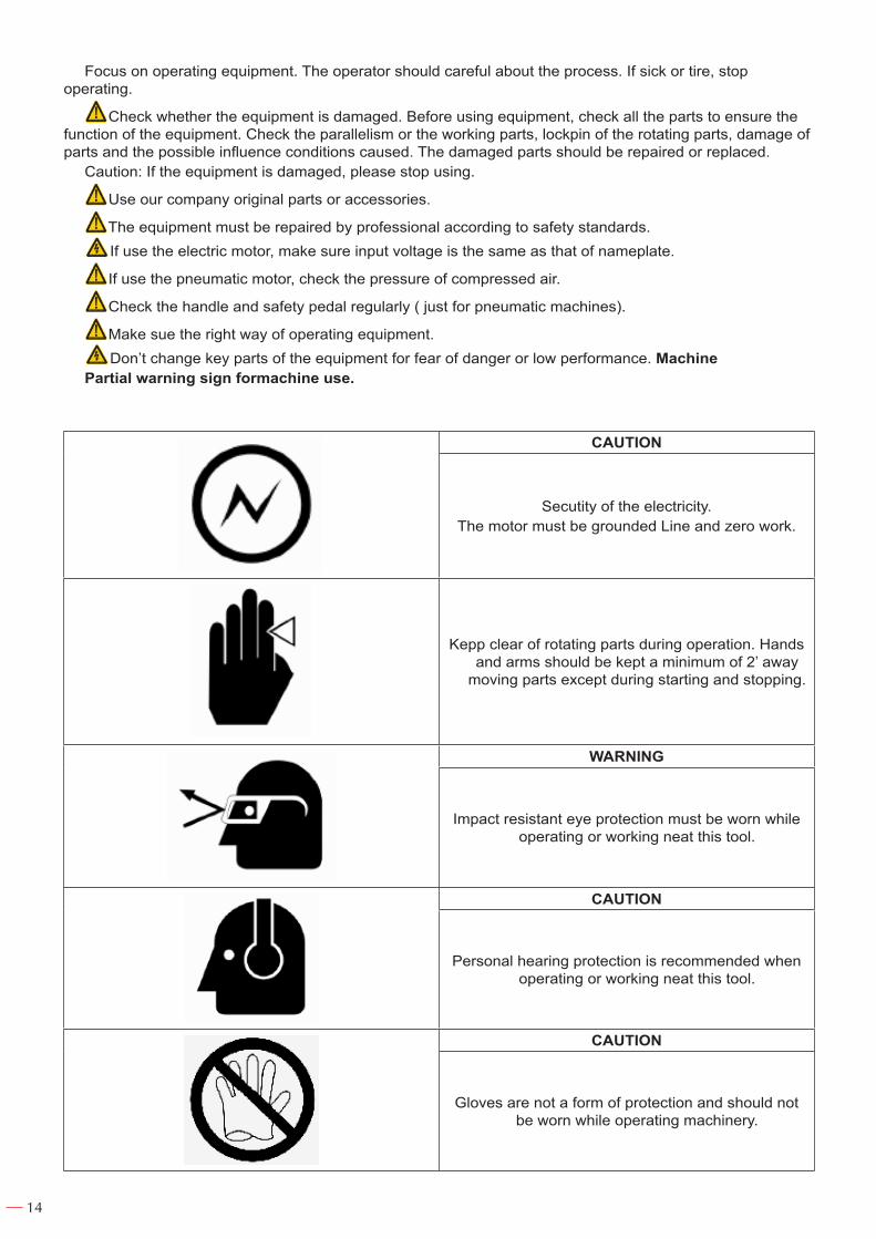
PRECAUCIÓN
Seguridad de la electricidad.El motor debe ser conectado a tierra en línea y con
trabajo cero.
Manténgase alejado de piezas rotatorias durante la operación.
Las manos y los brazos deben ser mantenidos a un mínimo de 2” de las partes móviles excepto
durante el inicio y parada.
ATENCIÓN
La protección ocular resistente al impacto debe ser llevada mientras se opera o trabaja
ordenadamente esta herramienta.
PRECAUCIÓN
La protección auditiva personal es recomendada cuando opere o trabaje ordenadamente esta
herramienta.
PRECAUCIÓN
Los guantes no son una forma de protección y no se deben llevar puestos mientras opere la máquina.

5
SECCION 3
ESPECIFICACIONES DE LA MÁQUINA
3.1 PRINCIPIO DE TRABAJO
Las máquinas para corte y biselado de tubos son fijadas mediante ektexine por las pinzas en el anillo estacionario. Adopta el Motor Eléctrico para conducir el anillo a rotar, lo que hace que los dos postes de la herramienta roten alrededor de la tangente del tubo. Trabaja conjuntamente con el poste de alimentación de la herramienta en el anillo estacionario para finalizar el proceso de corte y biselado.
3.2 RANGO DE APLICACIÓN
Nuestra compañía es una compañía avanzada en el mundo, que está especializada en la fabricación de máquinas portátiles de corte y biselado de tubo. Los modelos de máquinas de corte y biselado son diseñados para tubos de 10-1300mm (OD), con utilidad incomparable. La máquina puede procesar los tubos y la cara de las bridas. Nuestros productos pueden ajustarse a su demanda para cualquier grosor de los tubos.
3.3 CARACTERÍSTICAS DE OPERACIÓN
1. Peso ligero, transporte cómodo, adecuado para líneas de tuberías in situ y para trabajos de reparación rápida.
2. Poco espacio de montaje, pegar a los tubos, gran seguridad.3. Formato simple y compacto, reduce en un 40% las piezas de trabajo comparado con productos de la
misma funcionalidad.4. Función potente, usada para cortar y biselar al mismo tiempo.5. Gran intensidad, larga vida de servicio, gran precisión de proceso.6. Pinza para tubo simple, sólo llave de un tamaño para el ajuste.7. Varios tipos de manejo, adecuados para diferentes lugares de trabajo y procesos requeridos.
3.4 DETALLES DE EMPAQUETADO
La máquina está colocada dentro de una carcasa portátil de madera con adaptadores, cuchillas para herramienta y herramientas para el montaje. Nuestra compañía proporciona todas las herramientas importantes para la operación, consulte la lista de partes del producto para conocer los detalles.
SECCION 4
ESPECIFICACIONES TÉCNICAS
4.1 MÁQUINA ELÉCTRICA PARA CORTE Y BISELADO DE TUBOS
6
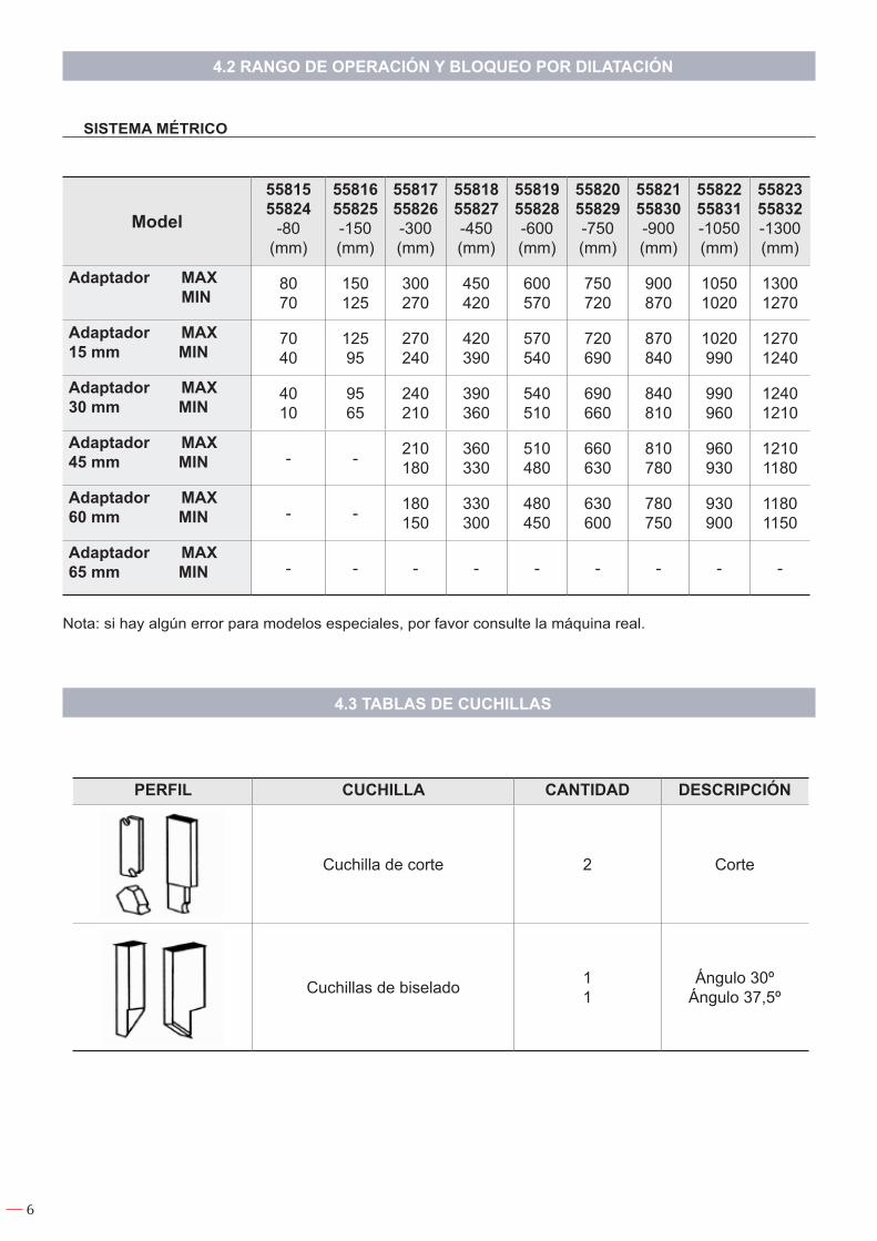
4.2 RANGO DE OPERACIÓN Y BLOQUEO POR DILATACIÓN
SISTEMA MÉTRICO
Nota: si hay algún error para modelos especiales, por favor consulte la máquina real.
4.3 TABLAS DE CUCHILLAS
Model
5581555824
-80(mm)
5581655825-150(mm)
5581755826-300(mm)
5581855827-450(mm)
5581955828-600(mm)
5582055829-750(mm)
5582155830-900(mm)
5582255831-1050(mm)
5582355832-1300(mm)
Adaptador MAX MIN
8070
150125
300270
450420
600570
750720
900870
10501020
13001270
Adaptador MAX15 mm MIN
7040
12595
270240
420390
570540
720690
870840
1020990
12701240
Adaptador MAX30 mm MIN
4010
9565
240210
390360
540510
690660
840810
990960
12401210
Adaptador MAX45 mm MIN - - 210
180360330
510480
660630
810780
960930
12101180
Adaptador MAX60 mm MIN - - 180
150330300
480450
630600
780750
930900
11801150
Adaptador MAX65 mm MIN - - - - - - - - -
PERFIL CUCHILLA CANTIDAD DESCRIPCIÓN
Cuchilla de corte 2 Corte
Cuchillas de biselado 11
Ángulo 30ºÁngulo 37,5º

7
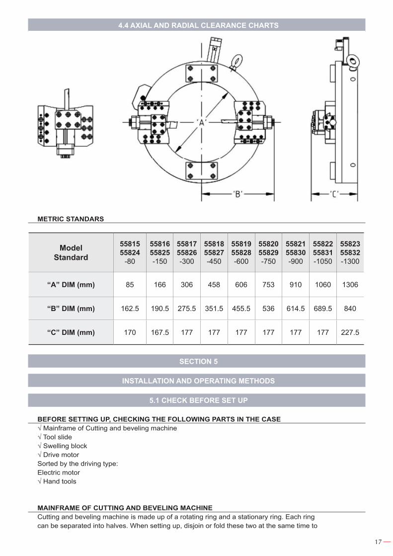
4.4 TABLAS DE TOLERANCIAS AXIAL Y RADIAL
NORMA MÉTRICA
SECCION 5
INSTALACIÓN Y MÉTODOS DE OPERACIÓN
5.1 COMPROBAR ANTES DE MONTAR
ANTES DE MONTAR, COMPROBAR LAS SIGUIENTES PARTES EN EL CASO√ Ordenador central de la máquina de corte y biselado√ Deslizado de la herramienta√ Bloqueo de hinchamiento√ Unidad motrizClasificados por el tipo de forma motriz:Motor eléctrico √ Herramientas de mano
ORDENADOR CENTRAL DE LA MÁQUINA DE CORTE Y BISELADOLa máquina de corte y biselado está formada por un anillo rotatorio y un anillo estacionario. Cada anillo
puede ser separado en mitades. Al montarla, separe o plegue estos dos al mismo tiempo para hacer más fácil la conexión a los tubos. El ordenador central ha sido prefijado y ajustado por la fábrica.
ModelStandard
5581555824
-80
5581655825-150
5581755826-300
5581855827-450
5581955828-600
5582055829-750
5582155830-900
5582255831-1050
5582355832-1300
“A” DIM (mm) 85 166 306 458 606 753 910 1060 1306
“B” DIM (mm) 162.5 190.5 275.5 351.5 455.5 536 614.5 689.5 840
“C” DIM (mm) 170 167.5 177 177 177 177 177 177 227.5

8
DESLIZADO DE LA HERRAMIENTANuestros productos tienen el deslizamiento estándar de un nivel.
BLOQUEO DE HINCHAMIENTO Parte necesaria para el proceso de corte y biselado de diferentes tipos y tamaños de tubos.
UNIDAD MOTRIZ Motor eléctrico
HERRAMIENTAS DE MANOCada máquina de corte y biselado es suministrada con herramientas de mano(incluyendo cuchillas) para
el ajuste y la operación.
5.2 INSTALACIÓN Y PROCEDIMIENTOS DE TRABAJO
1. Saque el ordenador central de la carcasa de madera:Precaución: si el modelo de la máquina es por encima de 450mm, por favor use más personal o muchas
herramientas, así como cuerda para quitar el ordenador central para que no cause lesiones a operadores o daño a las máquinas.
2. Deslice el pasador dentro del Anillo Circular.Este pasador puede evitar que el Anillo Circular se afloje cuando la máquina se abre para trabajo en serie.3. Instalar el deslizamiento de la herramientaA. Seis agujeros y cuatro pasadores en dos líneas en la parte trasera del deslizamiento de la herramienta.
Los pasadores se usan para establecer la posición, tres agujeros representan posibles posiciones de instalación: posición alta, media y baja.
B. Deslice los pasadores en el agujero apropiado.C. Atornille cuatro tornillos M8 Inner Hex y ajuste el deslizamiento de la herramienta en el anillo rotatorio.4. Atornille tres tornillos M8 Inner Hex e instale el mecanismo de unión.Precaución: instale un o dos bloqueos de extensión para el alcance dado.Precaución: el mecanismo de unión está instalado adecuadamente, la unión de alimentación debe ser
extraída en diferentes posiciones.5. Instalar las cuchillas de corte y biselado en una posición adecuada en el poste de herramientas.Precaución: asegúrese de que la hoja de cada cuchilla rota en sentido horario.6. Instale el plato cubridor del poste de herramienta para fijar la posición de la cuchilla. Atornille los cuatro tornillos Inner Hex en cada plato cubridor del poste de herramienta.Precaución: la distancia entre el plato cubridor de herramienta debe ser el mismo en ambos lados de las
cuchillas.7. Después de instalar el plato cubridor de deslizamiento de la herramienta, atornille dos tornillos Inner
Hex en el centro del plato cubridor.8. Mida el diámetro exterior de los tubos para ver si el bloqueo de hinchamiento es necesario, si
es necesario, selecciones el adecuado e instálelo( consulte la SECCIÓN de selección de bloqueo de hinchamiento). Si es sólo para cortar o conectar tubos, vaya directamente al paso 11 para proceso de corte, de otra forma vaya al paso 9.
9. En cuanto al trabajo de biselado de la pieza: Deslice el ordenador central hasta el final. El equipo de elevación como “Elevador” puede ser requerido para ello.
10. Vaya al paso 12.11. Proceso de conexión.A. Afloje todos los tornillos de cierre en el anillo.B. Separe la máquina en dos mitades. Hágalas igual para evitar conglutinación.C. Instale la mitad superior (la que tiene piñón) a la parte superior del tubo de proceso.D. Instale la otra mitad a la parte inferior del tubo de proceso, uniendo dos partes con la clavija de
localización.E. Apriete un tornillo de cierre en el anillo rotatorio, y luego apriete otro tornillo de cierre para unir los
anillos rápidamente y efectivamente.Precaución: Apriete todos los tornillos cuidadosamente para evitar daños al ordenador central.12. Después de que el ordenador central está firmemente instalado en los tubos, extraiga la clavija circular
de cierre.

9
Precaución: asegúrese de que todos los tornillos circulares de cierre están apretados antes de continuar el proceso de instalación.
13. Ajuste el bloqueo de hinchamiento fijado apuntando a la posición 12 en punto o cerca de 12 en punto. Apriete el perno fijado del bloqueo de hinchamiento para hacerlo equivalente a la distancia del ordenador central a la parte superior e inferior de los tubos.
14. Ajuste en la posición de 6 en punto el bloqueo de hinchamiento fijado, y apriete el perno. De la misma forma que en el paso 13.
15. Ajuste en la posición de 3 en punto el bloqueo de hinchamiento fijado, apriete el perno. De la misma forma que en el paso 13. Para este momento, el ordenador central está casi en la posición adecuada.
16. Use el cuadrado proporcionado para ajustar el ángulo adecuado de la máquina y amplíe el diámetro de los tubos.
Precaución: aquí, la máquina todavía puede moverse. Si es necesario, afloje el perno fijado a la posición de 3 en punto y 9 en punto para ajustarlos de nuevo.
17. Cuando el ángulo entre la máquina y el tubo sea un ángulo recto, apriete el tornillo de bloqueo de hinchamiento, y fije el ordenador central a los tubos.
18. Centre la máquina.A. Rote la cuchilla de corte a la posición de 12 en punto a mano.B. Baje la cuchilla a la posición que está 2mm a la parte superior del diámetro externo.C. Rote la cuchilla a la posición a la posición de 6 en punto, ajuste al centro el bloqueo de hinchamiento
fijado.C1. Si la cuchilla en la posición de 6 en punto está más cerca a esa posición que la que está en las 12
en punto, afloje el perno fijo a la posición 12 en punto, luego apriete el perno a la posición de 6 en punto. Haciendo esto, hará que la máquina se aleje de la ektexina del tubo a la posición de 6 en punto y cerca de la posición de 12 en punto.
19. Repetir los pasos de arriba si es necesario.20. Después de eso, ajuste la cuchilla para asegurarse de que puede funcionar correctamente y evitar
daños.A. La distancia extensible desde la cuchilla al fondo del poste de herramienta resulta en un espesor de
pared +3mm.B. La distancia extensible desde la cuchilla de biselado al fondo del poste de herramienta, resulta en un
espesor de pared +2mm.Precaución: Fije la cuchilla de este modo para asegurarse de que la cuchilla pude ir primero a lo largo del
tubo, y luego haga que la cuchilla de biselado funcione efectivamente.Precaución: Asegúrese de que la cuchilla toca el lado correcto o la línea de corte del tubo, y luego21. Tiempo de alimentación del sistema de rueda estrella.A. Rote la rueda estrella en sentido horario para asegurarse de que no hay espacio entre el vástago de
tornillo de rueda estrella y la tapa.B. Haga que cualquier punto de la rueda estrella apunte a la línea roja en la parte superior del cursor de la
herramienta.C. Ajuste el otro cursor de herramienta del mismo modo.D. Presione el enlace de alimentación y la alimentación de la rueda estrella.22. Instale la unidad motriz, afloje dos tornillos de 8mm en la parte trasera del alojamiento del piñón.23. Ajuste dos agujeros de perno en el motor, posicione la brida en el motor usando un el tornillo en el
piñón y empujando la brida al tornillo superior.24. Apriete dos tornillos para fijar el motor.25. Inicialice la máquina y confirme la holgura de la cuchilla.A. Rote el cursor de la cuchilla de la rueda estrella en sentido horario hasta que haga que la herramienta
esté a 2mm de la ektexina de los tubos.B. Conecte el suministro de electricidad.C. Encienda el motor, rote alrededor de la ektexina del tubo para comprobar la holgura.D. Ajuste para cumplir las necesidades.26. Empiece el proceso de corte.Primeramente, haga que el poste de herramienta rote a una velocidad uniforme para comprobar si la
rueda de estrella está adecuadamente temporizada. Si la rueda de estrella no puede engranar el enlace de alimentación suavemente, corte la potencia y reajuste temporizando el proceso de rueda de estrella (paso 21, de la A a la C).
27. Ajuste la velocidad de rotación del poste de herramienta.28. Al maquinar, asegúrese de que hay gran cantidad de refrigerante para procesado constante.Precaución: al cortar, haga que el cursor de la cuchilla vaya por la línea roja.

10
Precaución: preocúpese por los tubos que caen al cortar piezas de largas.29. Después de completar el corte, afloje el gatillo del motor o apague la electricidad, y desmantele el
proceso.Precaución: Después de mecanizar, asegúrese de que la máquina está limpia, no hay residuos
metálicos, no queda refrigerante en el almacenamiento de la máquina. Abra la máquina en dos mitades y compruebe si hay algún residuo en el lado del cursor.
30. Extraiga el enlace de alimentación, cuchillas de corte y biselado.31. Afloje el bloqueo de hinchamiento ajustado e inserte el pasador de cierre en el anillo del ordenador
central.
SECCION 6
MANTENIMIENTO Y REPARACIÓN
El mantenimiento y reparación deben ser operados por técnicos competentes.Para garantizar que la máquina trabaja bien, las partes originales y accesorios son preferibles.Precaución: Antes del mantenimiento del equipo, asegúrese de que la electricidad está cortada.Guarde el paquete original en condiciones para transportar equipos y accesorios convenientemente y con
rapidez.Mantenga el equipo limpio para hacer que el equipo trabaje en las condiciones óptimas.Después de usarlo en cualquier momento, el equipo debe ser limpiado con cepillo y grasa antioxidante.No ponga el equipo en un lugar húmedo y sucio.Precaución: No ponga nada en el eje de rotación.Precaución: Limpie el equipo con cepillo.Advertencia: No limpie el equipo con aire comprimido.Antes de usarlo en cualquier momento, por favor limpie el equipo y asegúrese de que no hay restos.Desmonte la pieza de trabajo y la grasa lubricante por profesionales todos los años.Limpie la máquina regularmente y compruebe la condición de uso del deterioro de piezas de trabajo. Si
pone la máquina en la caja de almacenamiento, opere como sigue:1. Compruebe el cable de alimentación.2. Compruebe la tensión del cursor de herramienta. Si se afloja, ajuste el caracol de cuña en el cursor de
herramienta.Ajuste la tensión del cursor de herramienta:1. Apriete el tornillo inner Hex, el cursor de herramienta toca un poco.2. Rote la rueda de estrella para comprobar la tensión del rechequeo del cursor de herramienta.
Sistema de rodamientos:Precaución: No mueva el rodamiento fuera del punto de establecimiento, o el anillo probablemente cause
daños. El sistema de rodamientos del equipo ha sido instalado cuando la máquina abandona la fábrica. El ajuste de todo el sistema de rodamientos debe ser operado por técnicos de mantenimiento concedido por nuestra compañía. Si necesita apoyo o ayuda, por favor contacte con nuestra compañía o representante local.
SECCION 7
DOCUMENTOS TÉCNICOS DE LOS PRODUCTOS
Los documentos técnicos de los productos incluyen montaje general de la tabla de máquinas. Por favor refié-rase al apéndice de instrucción para detalles, como sigue:
a) Tabla de máquina principalb) Tabla de cursor de herramienta

11
SECCION 8
PROBLEMAS Y SOLUCIONES
Problema Posible Causa Solución
La máquina no funcionaCable de alimentación o
suministro de aire no conectado
Comprobar cable de alimentación o suministro de aire
Pieza de trabajo se desplaza durante operaciones de corte Aflojamiento de abrazadera fijada Comprobar tensión en el mango
de la abrazadera fijadaCalidad de mecanizado pobre Cuchillas desafilladas y dañadas Remplace o raspe la cuchilla
El cursor de herramienta no puede alimentar
Cabeza de cortador rota o no en la posición de trabajo
Remplace la cabeza del cortador o ajuste a la posición de trabajo
La cuchilla salta y se atascaPiñón planetario en el cursor
de herramienta no ajustado correctamente
Reajustar
Si un problema persiste o no esta listado en la tabla de arriba, por favor cese la operación y consulte al fabricante para instrucción adicional.
NOTAS
¡IMPORTANTE!
El fabricante no se responsabiliza de los daños o mal funcionamiento de la máquina en caso de que no se use correctamente o se haya utilizado para trabajos para los que no está diseñada.
Para pedir cualquier repuesto, mirar en el dibujo de despiece el número de la pieza deseada.
Según la directiva sobre residuos eléctricos de aparatos eléctricos y electrónicos (RAEE), éstos deberán recogerse y tratarse por separado. Si en el futuro tiene que deshacerse de este producto, no se deshaga de él junto con la basura doméstica. Póngase en contacto con su distribuidor para proceder a su reciclaje de manera gratuita cuando sea posible.
GARANTÍA
El fabricante garantiza al comprador de ésta máquina la garantía total durante 12 meses de las piezas con defectos de fabricación.
Esta garantía no cubre aquellas piezas que por su uso normal tienen un desgaste.
Nota: para obtener la validez de la garantía, es absolutamente imprescindible que complete y remita al fabricante el documento de “CERTIFICADO DE GARANTIA”, dentro de los siete dias a partir de la fecha de compra.

12
TABLE OF CONTENTS
Section 1 ...........................................................................................................................................13 Prelogue ...............................................................................................................................13 Section 2 ...........................................................................................................................................13 Safety instructions ................................................................................................................13 Section 3 ...........................................................................................................................................15 Machine specifications ..........................................................................................................15 3.1 Working principle ............................................................................................................15 3.2 Application range ............................................................................................................15 3.3 Operating features ..........................................................................................................15 3.4 Package details ..............................................................................................................15Section 4 ...........................................................................................................................................15 Technical specifications ........................................................................................................15 4.1 Electric pipe cutting and beveling machine .....................................................................15 4.2 Working range and swelling block ..................................................................................16 4.3 Toolbit charts ...................................................................................................................16 4.4 Axial and radial clearance charts ....................................................................................17Section 5 ...........................................................................................................................................17 Installation and operating methods .......................................................................................17 5.1 Check before set up ........................................................................................................17 5.2 Installation and working procedures ...............................................................................18Section 6 ...........................................................................................................................................20 Maintenance and repair ........................................................................................................20 Section 7 ...........................................................................................................................................20 Technical documents of products .........................................................................................20Section 8 ...........................................................................................................................................20 Troubles and solutions ..........................................................................................................20
ENGLISH

13
SECTION 1
PRELOGUE
Thanks for purchasing our pipe cutting and beveling machines.This instruction introduces the principle, instruction, function, technical specifications, delivery and
installation, operation methods and safety instructions. Please read the instruction beforeusing the equipment for correct installation and use.
SECTION 2
SAFETY INSTRUCTIONS
Our Company takes great pride in manufacturing safe, quality products with user safety apriority. Our Company recommends that all users comply with the following safety rules and instructions when operating our equipment. For your safety and the safety of others, read and understand these safety recommendations and operating instructions before operating.
Warn! To avoid unforeseeable environment or man causes, before operating the machines, the users should read the instruction carefully, understand the operating procedures and use range. Keep the manual clean and well for reference at any time.
Regarding the safety instructions, sorted into two grades: Danger and Caution.
Danger: danger causes if the machine is operated wrongly, probably, death or serious injury will cause.
Caution: danger causes if the machine is operated wrongly, probably, medium or gentle injury and damage to equipment will cause.
Different cases probably cause serious result. The caution and danger notes should be obeyed strictly.
The equipment must be operated by qualified technician, who has received training about how to operate the machine.
The equipment can just be applied for corresponding design purpose.
Keep working place clean, messy working site will increase the risk of accidents.
Considering the working environment of operating, don’t get the equipment wet and don’t use the equipment in humid circumstance. Make the machine work in good conditon.
Don’t operate the electric switch, button with wet hands for fear of electric shock .Protect the body from injury of electric shock, and avoid touch electric parts.
Put the euqipment in dry and safe circumstance if the machine has not been used for a long time.Wear suitable work clothes. Don’t wear loose clothing and jewelry.
Keep clear of rotating parts during opeating.
Wear impact resistant eye and ear protection while operating. If much dust, wear the dustproof respirator or mask.
Don’t overuse the cable. Don’t pull the equipment with the cable or sintak the cable to cut off the power. The cable should be kept away from heat power, oil dirt and sharp-pointed tools. Check the cable regularly, change it if damaged and repair it if loose. Maintain the equipment regularly. To make the machine work in good performance, keep it clean. Add oil lubricant and change parts as per operating rules.
Before maintenance or change accessories, such as Tool Bits, make sure the power plug has been pulled out.
Avoid start up the euqipment unconsciously. When plug in, don’t put hands on the switch and ensure it is cut off.
Use suitable extending power board. If the equipment is used in outdoor, the power board must be restricted to the outdoor use.
14
Focus on operating equipment. The operator should careful about the process. If sick or tire, stop operating.
Check whether the equipment is damaged. Before using equipment, check all the parts to ensure the function of the equipment. Check the parallelism or the working parts, lockpin of the rotating parts, damage of parts and the possible influence conditions caused. The damaged parts should be repaired or replaced.
Caution: If the equipment is damaged, please stop using.
Use our company original parts or accessories.
The equipment must be repaired by professional according to safety standards.If use the electric motor, make sure input voltage is the same as that of nameplate.
If use the pneumatic motor, check the pressure of compressed air.
Check the handle and safety pedal regularly ( just for pneumatic machines).
Make sue the right way of operating equipment.Don’t change key parts of the equipment for fear of danger or low performance. Machine
Partial warning sign formachine use.
CAUTION
Secutity of the electricity.The motor must be grounded Line and zero work.
Kepp clear of rotating parts during operation. Hands and arms should be kept a minimum of 2’ away
moving parts except during starting and stopping.
WARNING
Impact resistant eye protection must be worn while operating or working neat this tool.
CAUTION
Personal hearing protection is recommended when operating or working neat this tool.
CAUTION
Gloves are not a form of protection and should not be worn while operating machinery.

15
SECTION 3
MACHINE SPECIFICATIONS
3.1 WORKING PRINCIPLE
Pipe Cutting and Beveling Machines are fixed the ektexine of the pipes by the clamps on the Stationary Ring. It adopts Electric Motor to drive the ring rotate, which makes two tool posts rotate around the pipe tangent. It coworks with the Feed Tool Post on the Stationary
Ring to finish the cutting and beveling process.
3.2 APPLICATION RANGE
Our company is an advanced company in the world, which is specialized in manufacturing portable pipe cutting and beveling machine. The models of pipe cutting and beveling machine is designed for 10-1300mm (OD) pipes, with incomparable utility. The machine can process the pipes and flange face. Our products can meets your demand for any thickness of the pipes.
3.3 OPERATING FEATURES
1. Light weight, convenient carry, suitable for on site pipelines and rush repair working.2. Low clearance, stick to the pipes, high security.3. Simple and compact frame, reduce 40% work pieces compared with products with the samefunction.4. Powerful function, used for cutting and beveling at the same time.5. High intensity, long service life, high process precision.6. Simple pipe clamp, just one size wrench for adjustment.7. Various Driving type, suitable for different working place and process requirement.
3.4 PACKAGE DETAILS
The machine is placed in a portable wooden case with fittings, tool bits and tools for assembly.Our company provides all the important operating tools, refer to the product parts list for details.
SECTION 4
TECHNICAL SPECIFICATIONS
4.1 ELECTRIC PIPE CUTTING AND BEVELING MACHINE

16
4.2 WORKING RANGE AND SWELLING BLOCK CHARTS
METRIC SYSTEM
Note: if any error for special models, please refer to the actual machine.
4.3 TOOL BIT CHARTS
Model
5581555824
-80(mm)
5581655825-150(mm)
5581755826-300(mm)
5581855827-450(mm)
5581955828-600(mm)
5582055829-750(mm)
5582155830-900(mm)
5582255831-1050(mm)
5582355832-1300(mm)
Swelling block MAX MIN
8070
150125
300270
450420
600570
750720
900870
10501020
13001270
Swelling block MAX15 mm MIN
7040
12595
270240
420390
570540
720690
870840
1020990
12701240
Swelling block MAX30 mm MIN
4010
9565
240210
390360
540510
690660
840810
990960
12401210
Swelling block MAX45 mm MIN - - 210
180360330
510480
660630
810780
960930
12101180
Swelling block MAX60 mm MIN - - 180
150330300
480450
630600
780750
930900
11801150
Swelling block MAX65 mm MIN - - - - - - - - -
PATTERN PART NAME QUANTITY DESCRIPTION
Cut-off toool bit 2 Cut-off
Bevelling blades 11
Angle 30ºAngle 37,5º
17
4.4 AXIAL AND RADIAL CLEARANCE CHARTS
METRIC STANDARS
SECTION 5
INSTALLATION AND OPERATING METHODS
5.1 CHECK BEFORE SET UP
BEFORE SETTING UP, CHECKING THE FOLLOWING PARTS IN THE CASE√ Mainframe of Cutting and beveling machine√ Tool slide√ Swelling block√ Drive motorSorted by the driving type:Electric motor √ Hand tools
MAINFRAME OF CUTTING AND BEVELING MACHINECutting and beveling machine is made up of a rotating ring and a stationary ring. Each ringcan be separated into halves. When setting up, disjoin or fold these two at the same time to
ModelStandard
5581555824
-80
5581655825-150
5581755826-300
5581855827-450
5581955828-600
5582055829-750
5582155830-900
5582255831-1050
5582355832-1300
“A” DIM (mm) 85 166 306 458 606 753 910 1060 1306
“B” DIM (mm) 162.5 190.5 275.5 351.5 455.5 536 614.5 689.5 840
“C” DIM (mm) 170 167.5 177 177 177 177 177 177 227.5
18
make it easier to be connected to the pipes. The mainframe has been preset and adjusted by thefactory.
TOOL SLIDEOur products standard tool slide of one level.
SWELLING BLOCK Necessary part for cutting and beveling process of different types and sizes pipes.
DRIVING MOTOR Electric motor
HAND TOOLSEach cutting and beveling machine is supplied with hand tools(including tool bits) forsetting and operating.
5.2 INSTALLATION AND WORKING PROCEDURES
1. Remove the mainframe from wooden case.Caution: if the model of the machine is above 450mm, please use more workforce or plenty tools, such as
rope to remove the mainframe lest it causes injury to operators or damage to machines.2. Slide the Lock Pin into the Circular RingThis pin can prevent the Circular Ring from loosening when the machine is opened for series working.3. Install Tool SlideA. Six holes and four Lock Pins in two lines on the back of the Tool Slide. Lock Pins are used for setting
position, three holes represent possible installing position: high, mediate and low position.B. Slide Pins into proper hole.C. Screw down four M8 Inner Hex Screws and fix the Tool Slide on the Rotating Ring.4. Screw down three M8 Inner Hex Screw and install Link Mechanism.Caution: set up one or two extending blocks as per the given scope.Caution: the Link Mechanism is properly installed, feed link should be pull out in separate positions.5. Install cutting and beveling Tool Bits in a proper position on the Tool Post.6. Install Tool Post cover plate to fasten Tool bit position.Screw down the four Inner Hex Screws on each Tool Post Cover Plate.Caution: the distance between Tool Slide Cover Plate should be the same on both sides of the cutting Tool
Bits.7. After installing the Tool Slide Cover Plate, screw down two Inner Hex Screws in the center of the cover
plate.8. Measure the external diameter of pipes to see whether the Swelling Block is needed, if needed, select
proper one and install it( refer to the ● SECTION of Swelling Block selection). If just for cutting and connecting pipes, come directly to Step 11 for cutting process, otherwise come to Step 9.
9. Regarding beveling work piece: Slide the mainframe to the end. The lift equipment like “Lifter” may be required for it.
Caution: when installing the machine on the pipes, make the clearance between drive motor and link mechanism convenient for use.
10. Come to Step 12.11. Connecting process.A. Loosen all Lock Screw on the ring.B. Separate the machine into halves. Make them equal to avoid conglutinating.C. Install the upper half ( the one with pinion) to the top of the process pipe.D. Install the other half to the bottom of the process pipe, jointing two parts with Locating Dowel.E. Tighten one Lock Screw on the Rotating Ring, and then tighten another Lock Screw to joint the rings
quickly and effectively.Caution: tighten all the screws carefully to avoid damage to mainframe.

19
12. After the mainframe is firmly installed on the pipes, take away circular Lock Pin.Caution: make sure all the circular Lock Screw tightened before continuing the installing process.13. Adjust the fixed Swelling Block pointed to the position of 12 o’clock or close to 12’clock.Tighten fixed bolt of Swelling Block to make it equivalent that the distance from the mainframe to the top
and the bottom of the pipes.14. Adjust the fixed Swelling Block at the position of 6 o’clock, and tighten the bolt. The sameway as Step 13.15. Adjust the fixed Swelling Block at the position of 3 o’clock, tighten the bolt. The same way as Step 13.
by here, the mainframe is almost at a proper position.16. Use the provided square to adjust the right and angle of machine and extend diameter of pipes.Caution: here, the machine still can move. If necessary, loosen the fixed bolt at position of 3 o’clock and 9
o’clock to adjust them again.17. When the angle between machine and pipe becomes a right angle, tighten Swelling Block Screw, and
fix the mainframe on the pipes.18. Center the machineA. Rotate the Cut-off Tool Bit to the position of 12 o’clock by hand.B. Lower Tool Bit to the position which is 2mm to the upper of external diameter. C. Rotate Tool Bit to the position of 6 o’clock, adjust the fixed swelling block to the center.C1. If the Tool Bit at the position of 6 o’clock is closer to that at position of 12 o’clock, loosen the fixed bolt
at the position of 12 o’clock, then tighten the bolt at the position of 6 o’clock. By doing this, it will make the machine move away from ektexine of pipe at the position of 6 o’clock and close to 12 o’clock position.
19. Repeat the steps above if necessary.20. Thereafter, adjust Tool Bit to make sure it can run normally and avoid damage.A. The extending distance from Cutting Tool Bit to the bottom of Tool Post equals to wall thickness + 3mm.B. the extending distance from Beveling Tool Bit to the bottom of Tool Post equals to wall thickness + 2mm.Caution: Fix Tool Bit in this way to make sure that Cutting Tool Bit can go first through thepipe, and then make the Beveling Tool Bit work effectively.Caution: Make sure that Tool Bit touch the correct side or the pipe’s cutting line, and then A.21. Rotate Star wheel clockwise to make sure no clearance between Star wheel Screw Stem and crew cap.B. Make any point of the Star wheel point to red line on the top of Tool Slide.C. Adjust the other Tool Slide by the same way.D. Press Feed Link and mess Feed Star wheel.22. Install Driving Motor, loosen two 8mm screws on the back of Pinion Housing.23. Adjust two bolt holes on the motor, position the flange on the motor by using the screw on the pinion
and push the flange to upper screw.Caution: Drive Motor can be installed in different positions for operators’ convenience.24. Tighten two screws to fasten the motor.25. Start up the machine and confirm the Tool Bit clearance.A. Rotate Cutting Tool Slide Star wheel clockwise until it make the tool 2mm off the ektexine of pipes.B. Connect electricity.C. Switch on the engine, rotate around the ektexine of the pipe to check theclearance.D. Adjust to meet needs.26. Start cutting processAt first, make the tool post rotate at a uniform speed to check if the Star wheel is properly timed. If the Star
wheel can’t mesh the Feed Link smoothly, cut off the power and readjust by timing process of Star wheel (Step 21, from A to C).
27. Adjust rotation speed of Tool post.28. while machining, ensure plenty coolant for constant processing.Caution: while cutting, make Tool Slide within the red line.Caution: mind the falling pipes while cutting long work piece.29. After complete cutting, loosen the motor trigger or switch off the electricity, and dismantle the process.Caution: after machining, ensure the machine clean, no metal scraps, no coolant remainsfor machine storage. Open the machine into halves and check if there is any remains in the slide way.30. Pull out the Feed Link, Cutting and Beveling Tool Bit.31. Loose fixed Swelling Block and insert the Lock Pin into the mainframe ring.

20
SECTION 6
MAINTENANCE AND REPAIR
Maintenance and repair must be operated by proficient technician.To guarantee the machine to work well, original parts and accessories are preferable.Caution: before equipment maintenance, make sure the power is cut off.Keep original package well to transport equipments and accessories conveniently and promptly.Keep the equipment clean to make the equipment work on the optimal condition.After using every time, the equipment should be cleaned by brush and grease antirust.Don’t put the equipment in the humid and dirty place.Caution: don’t put any thing on the rotation axis. Caution: clean the equipment with brush.Warn: Don’t clean equipment with compressed air.Before using every time, please clean the equipment and ensure no remains.Take apart the work piece and grease lubricant by professionals every year.Clean the machine regularly and check the using condition of spoilage work pieces. If put the machine in
the storage case, operate as follows:1. Check the power cord.2. Check the tension of Tool Slide. If loose, adjust the wedge snail on the Tool Slide.Adjust the tension of Tool Slide:1. Tighten the inner Hex Screw, Tool Slide touches a little.2. Rotate the Star wheel to check the tension of recheck the Tool Slide.
BEARING SYSTEM:Caution: Do not move the bearing off the set-point, or the ring probably cause damage. The Bearing
system of equipment have been set when the machine leaves the factory. The adjustment of all the bearing system must be operated by maintenance technician granted by Our Company. If need support or help, please contact Our company or local representative.
SECTION 7
TECHNICAL DOCUMENTS OF PRODUCTS
Technical documents of products include general assembly chart of machines. Please refer to instruction appendix for details, as follows:a) Main Machine Chartb) Tool Slide Chart
SECTION 8
TROUBLES AND SOLUTIONS
Trouble Possible Cause Solution
Machine won’t work Power cord or air supply not connected Check power cord or air supply
Work piece shifts duringcutting operations
Loose fixed clamp Check tension on fixed clamp handle
Poor machining quality Blunt and damaged tool bits Replace or scrape the tool bit
Tool Slide can not feedBroken cutter head or not on the
working positionReplace cutter head or adjusted to
the working position
Tool bit jumps and jams Planet gear on the tool slide not well adjusted readjust

If a problem persists or is not listed in the above table, please cease operation and consult the manufacturer for additional instruction.
NOTES
IMPORTANT!
The maker will not take responsibility for damage or malfunction as a result of the machine being incorrectly used or, applied for a purpose for which it was not intended.
For ordering spare parts, please refer to the Spare Parts Drawing and note the needed number.
According to Waste Electrical and Electronic Equipment directive (WEEE), these ones must be collected and arranged separately. If you have to throw them out, please, do not use the usual rubbish. Please, contact your distributor for free recycling.
GUARANTEE
The maker guarantees to the machine owner 12 months against any manifacture defect.This guaranteee do not cover the parts wich are consumables.
Note: to apply the guarantee its necesary to send the “GUARANTEE CERTIFICATE” duly filled within one week after purchased the machine to the maker.


ARTICULO / ITEM / ARTICLE: .................................................................................................................................................
Nº DE SERIE / SERIE Nº / Nº SERIE: ....................................................................................................................................
DISTRIBUIDOR / DISTRIBUTOR / DISTRIBUTEUR: ..............................................................................................................
PAIS / COUNTRY / PAYS: ..........................................................................................................TEL.:....................................
FECHA DE VENTA / SALE DATE / DATE VENTE: ..................................................................................................................
NOMBRE DEL COMPRADOR / BUYER NAME / NOM DE L’ACHETEUR: ............................................................................
TEL. COMPRADOR / BUYER TEL. / TEL. DE L’ACHETEUR: ................................................................................................
CERTIFICADO DE GARANTIAGUARANTEE CERTIFICATECERTIFICAT DE GARANTIE
SELLO / STAMP / CACHET
EGA MASTER GARANTIZA AL COMPRADOR DE ESTA MAQUINA LA GARANTIA TOTAL (DURANTE 12 MESES), DE LAS PIEZAS CON DEFECTOS DE FABRICACION. ESTA GARANTIA NO CUBRE AQUELLAS PIEZAS QUE POR SU USO NORMAL TIENEN UN DESGASTE. PARA OBTENER LA VALIDEZ DE LA GARANTIA , ES ABSOLUTAMENTE IMPRESCINDIBLE QUE COMPLETE Y REMITA ESTE DOCUMENTO A EGA MASTER , DENTRO DE LOS SIETE DIAS A PARTIR DE LA FECHA DE COMPRA.
EGA MASTER GUARANTEES TO THE BUYER OF THIS MACHINE THE TOTAL WARRANTY (DURING 12 MONTHS), OF THE PIECES WITH MANUFACTURING FAULTS.THIS GUARANTEE DOES NOT COVER THOSE PIECES WORN OUT DUE TO A NORMAL USE. IN ORDER TO OBTAIN THE VALIDITY OF THIS WARRANTY , IT IS ABSOLUTELY NECESSARY TO FULFILL THIS DOCUMENT AND RESEND IT TO EGA MASTER WITHIN 7 DAYS FROM SALE DATE.
EGA MASTER GARANTIE A L’ACHETEUR DE CETTE MACHINE LA GARANTIE TOTALE (PENDANT 12 MOIS) DES PIECES AVEC DEFAUTS DE FABRICATION. CETTE GARANTIE NE COUVRE PAS LES PIECES QUE PAR UN USAGE NORMAL, SOIENT DETERIOREES. POUR OBTENIR LA VALIDITE DE LA GARANTIE, IL EST ABSOLUMENT IMPERATIF COMPLETER ET ENVOYER CE DOCUMENT EGA MASTER, DANS UN DELAI DE 7 JOURS A PARTIR DE LA DATE D’ACHAT.
EJEMPLAR PARA EGA MASTER / COPY FOR EGA MASTER / EXEMPLAIRE POUR EGA MASTER
ARTICULO / ITEM / ARTICLE: .................................................................................................................................................
Nº DE SERIE / SERIE Nº / Nº SERIE: ....................................................................................................................................
DISTRIBUIDOR / DISTRIBUTOR / DISTRIBUTEUR: ..............................................................................................................
PAIS / COUNTRY / PAYS: ..........................................................................................................TEL.:....................................
FECHA DE VENTA / SALE DATE / DATE VENTE: ..................................................................................................................
NOMBRE DEL COMPRADOR / BUYER NAME / NOM DE L’ACHETEUR: ............................................................................
TEL. COMPRADOR / BUYER TEL. / TEL. DE L’ACHETEUR: ................................................................................................
CERTIFICADO DE GARANTIAGUARANTEE CERTIFICATECERTIFICAT DE GARANTIE
SELLO / STAMP / CACHET
EGA MASTER GARANTIZA AL COMPRADOR DE ESTA MAQUINA LA GARANTIA TOTAL (DURANTE 12 MESES), DE LAS PIEZAS CON DEFECTOS DE FABRICACION. ESTA GARANTIA NO CUBRE AQUELLAS PIEZAS QUE POR SU USO NORMAL TIENEN UN DESGASTE. PARA OBTENER LA VALIDEZ DE LA GARANTIA , ES ABSOLUTAMENTE IMPRESCINDIBLE QUE COMPLETE Y REMITA ESTE DOCUMENTO A EGA MASTER , DENTRO DE LOS SIETE DIAS A PARTIR DE LA FECHA DE COMPRA.
EGA MASTER GUARANTEES TO THE BUYER OF THIS MACHINE THE TOTAL WARRANTY (DURING 12 MONTHS), OF THE PIECES WITH MANUFACTURING FAULTS.THIS GUARANTEE DOES NOT COVER THOSE PIECES WORN OUT DUE TO A NORMAL USE. IN ORDER TO OBTAIN THE VALIDITY OF THIS WARRANTY , IT IS ABSOLUTELY NECESSARY TO FULFILL THIS DOCUMENT AND RESEND IT TO EGA MASTER WITHIN 7 DAYS FROM SALE DATE.
EGA MASTER GARANTIE A L’ACHETEUR DE CETTE MACHINE LA GARANTIE TOTALE (PENDANT 12 MOIS) DES PIECES AVEC DEFAUTS DE FABRICATION. CETTE GARANTIE NE COUVRE PAS LES PIECES QUE PAR UN USAGE NORMAL, SOIENT DETERIOREES. POUR OBTENIR LA VALIDITE DE LA GARANTIE, IL EST ABSOLUMENT IMPERATIF COMPLETER ET ENVOYER CE DOCUMENT EGA MASTER, DANS UN DELAI DE 7 JOURS A PARTIR DE LA DATE D’ACHAT.
EJEMPLAR PARA EL CLIENTE / COPY FOR THE CUSTOMER / EXEMPLAIRE POUR LE CLIENT


C/ ZORROLLETA 11, POL. IND. JUNDIZ01015 VITORIA, SPAIN P.O.B. APTDO. 5005TEL. 34 - 945 290 001 FAX. 34 - 945 290 141