DCP8040 DCP8045D MFC8440 MFC8840D MFC8840DN Manuales Técnicos.pdf
362
SERVICE MANUAL MODEL: MFC8440/8840D/8840DN DCP8040/8045D/8045DN TRC Servicios s.r.l. Tel:2941 420643
Transcript of DCP8040 DCP8045D MFC8440 MFC8840D MFC8840DN Manuales Técnicos.pdf

8/9/2019 DCP8040 DCP8045D MFC8440 MFC8840D MFC8840DN Manuales Técnicos.pdf
http://slidepdf.com/reader/full/dcp8040-dcp8045d-mfc8440-mfc8840d-mfc8840dn-manuales-tecnicospdf 1/361
SERVICE MANUAL
MODEL: MFC8440/8840D/8840DNDCP8040/8045D/8045DN
TRC Servicios s.r.l. Tel:2941 420643

8/9/2019 DCP8040 DCP8045D MFC8440 MFC8840D MFC8840DN Manuales Técnicos.pdf
http://slidepdf.com/reader/full/dcp8040-dcp8045d-mfc8440-mfc8840d-mfc8840dn-manuales-tecnicospdf 2/361
© Copyright Brother Industries, Ltd. 2004 All rights reserved.
No part of this publication may be reproduced in any form or by any means without permissionin writing from the publisher.
Specifications are subject to change without notice.
Trademarks:
The brother logo is a registered trademark of Brother Industries, Ltd.
Apple, the Apple Logo, and Macintosh are trademarks, registered in the United States andother countries, and TrueType is a trademark of Apple computer, Inc.
Microsoft and MS-DOS are registered trademarks of Microsoft Corporation.
Windows is a registered trademark of Microsoft Corporation in the U.S. and other countries.
8/9/2019 DCP8040 DCP8045D MFC8440 MFC8840D MFC8840DN Manuales Técnicos.pdf
http://slidepdf.com/reader/full/dcp8040-dcp8045d-mfc8440-mfc8840d-mfc8840dn-manuales-tecnicospdf 3/361
MFC-8440/8840D/8840DN, DCP-8040/8045D/8045DNSERVICE MANUAL
i
PREFACE
This publication is a Service Manual covering the specifications, construction, theory ofoperation, and maintenance of the Brother machine. It includes information required for fieldtroubleshooting and repair--disassembly, reassembly, and lubrication--so that servicepersonnel will be able to understand machine function, to rapidly repair the machine and order
any necessary spare parts.
To perform appropriate maintenance so that the machine is always in best condition for thecustomer, the service personnel must adequately understand and apply this manual.
This manual is made up of six chapters and appendices.
CHAPTER 1: GENERAL
CHAPTER 2: INSTALLATION AND BASIC OPERATION
CHAPTER 3: THEORY OF OPERATION
CHAPTER 4: DISASSEMBLY AND RE-ASSEMBLY
CHAPTER 5: PERIODIC MAINTENANCE
CHAPTER 6: TROUBLESHOOTING
CHAPTER 7: MAINTENANCE MODE
APPENDIX 1: EEPROM CUSTOMIZING CODES
APPENDIX 2: INSTALLING THE UPDATE DATA
APPENDIX 3: FIRMWARE SWITCHS (WSW)
APPENDIX 4: CIRCUIT DIAGRAMS
Information in this manual is subject to change due to improvement or redesign of the product. All relevant information in such cases will be supplied in service information bulletins(Technical Information).
A thorough understanding of this printer, based on information in this service manual andservice information bulletins, is required for maintaining its print quality performance and forimproving the practical ability to find the cause of problems.

8/9/2019 DCP8040 DCP8045D MFC8440 MFC8840D MFC8840DN Manuales Técnicos.pdf
http://slidepdf.com/reader/full/dcp8040-dcp8045d-mfc8440-mfc8840d-mfc8840dn-manuales-tecnicospdf 4/361
TABLE OF CONTENTS
ii
TABLE OF CONTENTS
REGULATION............................................................................................ viii
SAFETY INFORMATION .............................................................................. x
CHAPTER 1 GENERAL........................................................................... 1-1
1. OVERVIEW ............................................................................................................ 1-1
2. SPECIFICATIONS.................................................................................................. 1-3
2.1 General.............................................................................................................................1-3
2.2 General (Continued) .........................................................................................................1-3
2.3 Print Media .......................................................................................................................1-4
2.4 Copy .................................................................................................................................1-4
2.5 Fax....................................................................................................................................1-52.6 Scanner ............................................................................................................................1-6
2.7 Printer ...............................................................................................................................1-6
2.8 Interfaces..........................................................................................................................1-7
2.9 Consumable Items ...........................................................................................................1-7
2.10 Network (LAN) Board (NC-9100h) ...................................................................................1-7
2.11 Computer Requirements ..................................................................................................1-8
2.12 Paper ................................................................................................................................1-9
2.12.1 Type and size of paper........................................................................................................1-9
2.12.2 Recommended paper..........................................................................................................1-9
2.12.3 Paper capacity of the paper trays........................................................................................1-9
2.12.4 Paper specifications for each paper tray.......................................... ................................ 1-10
2.13 Printable Area.................................................................................................................1-11
2.13.1 PCL5e/EPSON/IBM emulation..........................................................................................1-11
2.13.2 PCL6/BR-Script3 emulation ................................................. ............................................. 1-14
2.14 Print Speeds with Various Settings ................................................................................1-15
2.15 Toner Cartridge Weight Information...............................................................................1-15
3. SERIAL NO. DESCRIPTIONS .............................................................................. 1-16
CHAPTER 2 INSTALLATION AND BASIC OPERATION....................... 2-1
1. CONDITIONS REQUIRED FOR INSTALLATION................................................... 2-1
1.1 Power Supply....................................................................................................................2-1
1.2 Environment .....................................................................................................................2-1
2. UNPACKING........................................................................................................... 2-2
3. INSTALL THE MACHINE........................................................................................ 2-3
3.1 For All Users.....................................................................................................................2-3
3.1.1 Install the Automatic Document Feed (ADF) support.............. ...................................... ......2-4
3.1.2 Install the drum unit assembly............................................. ...................................... ..........2-5
3.1.3 Load paper into the paper tray ............................................. ............................................ ...2-6
3.1.4 Release the scanner lock..... ........................................... .......................................... ..........2-7
3.2 Installing the Driver & Software ........................................................................................2-83.2.1 For USB Interface Cable Users (For Windows
® 98/98SE/Me/2000 Professional/XP) ........2-8

8/9/2019 DCP8040 DCP8045D MFC8440 MFC8840D MFC8840DN Manuales Técnicos.pdf
http://slidepdf.com/reader/full/dcp8040-dcp8045d-mfc8440-mfc8840d-mfc8840dn-manuales-tecnicospdf 5/361
MFC-8440/8840D/8840DN, DCP-8040/8045D/8045DNSERVICE MANUAL
iii
3.2.2 For Parallel Interface Cable Users
(For Windows® 95/98/98SE/Me/2000 Professional/XP) ............................................ .......2-13
3.2.3 For Windows NT® Workstation Version 4.0 Users............................................................2-18
3.2.4 For Network Interface Cable Users
(For Windows® 95/98/98SE/Me/NT/2000 Professional/XP)..............................................2-20
3.2.5 For USB Interface Cable Users (For Mac® OS 8.6 to 9.2 Users)..... ................................. 2-23
3.2.6 For USB Interface Cable Users (For Mac® OS X 10.1/10.2.1 or greater Users)...............2-24
3.2.7 For Network Interface Cable Users (For Mac® OS 8.6 to 9.2 Users) ................................ 2-25
3.2.8 For Network Interface Cable Users (For Mac® OS X 10.1/10.2.1 or greater Users) .........2-26
CHAPTER 3 THEORY OF OPERATION................................................. 3-1
1. ELECTRONICS ...................................................................................................... 3-1
1.1 General Block Diagram ....................................................................................................3-1
1.2 Main PCB Block Diagram.................................................................................................3-2
1.3 Main PCB .........................................................................................................................3-3
1.3.1 CPU.....................................................................................................................................3-3
1.3.2 USB.....................................................................................................................................3-3
1.3.3 IEEE 1284 ................................................... .................................................... ....................3-4
1.3.4 ROM....................................................................................................................................3-4
1.3.5 Flash ROM........................................... .................................................. .............................3-5
1.3.6 SDRAM ................................................... ....................................................... .....................3-5
1.3.7 Optional RAM.................................................... ................................................. .................3-6
1.3.8 EEPROM.............................................................................................................................3-7
1.3.9 Reset circuit ............................................ ............................................... .............................3-7
1.3.10 Engine I/O .............................................. ................................................. ............................3-7
1.3.11 Panel I/O .............................................. .................................................. .............................3-7
1.3.12 Video I/O .............................................. .................................................. .............................3-8
1.3.13 Scanner control ........................................ .............................................. .............................3-81.3.14 Power supply.......................................................................................................................3-9
1.4 Engine PCB ....................................................................................................................3-10
1.5 Power Supply..................................................................................................................3-11
1.5.1 Low-voltage power supply....... ............................................ ............................................. .3-11
1.5.2 High-voltage power supply ........................................... ............................................ .........3-12
2. MECHANICS ........................................................................................................ 3-13
2.1 Overview of Printing Mechanism....................................................................................3-13
2.2 Scanner Mechanism.......................................................................................................3-14
2.3 Paper Transfer ...............................................................................................................3-15
2.3.1 Paper supply ............................................. ................................................. .......................3-152.3.2 Paper registration........................................ ............................................ ..........................3-15
2.3.3 Paper eject .............................................. .................................................. ........................3-16
2.3.4 Duplex printing ........................................... ............................................ ...........................3-16
2.4 Sensors ..........................................................................................................................3-17
2.4.1 Cover sensors ................................................. ................................................. .................3-17
2.4.2 Toner sensors ......................................... ............................................... ...........................3-17
2.4.3 Cassette sensor / Paper empty sensor ...................................... ....................................... 3-18
2.4.4 Paper eject sensor ............................................ ............................................. ...................3-18
2.4.5 MP-PE sensor ................................................ ................................................. ..................3-19
2.4.6 Document cover sensor ......................................... ............................................ ...............3-19
2.4.7 Document front sensor / Document rear sensor ................................... ............................ 3-20
2.4.8 DX-sensor PCB ASSY............................................................................... ........................3-20

8/9/2019 DCP8040 DCP8045D MFC8440 MFC8840D MFC8840DN Manuales Técnicos.pdf
http://slidepdf.com/reader/full/dcp8040-dcp8045d-mfc8440-mfc8840d-mfc8840dn-manuales-tecnicospdf 6/361
TABLE OF CONTENTS
iv
2.4.9 Rear cover sensor............................................ ............................................... ..................3-21
2.4.10 HP sensor .............................................. ................................................. ..........................3-21
2.5 Drum Unit .......................................................................................................................3-22
2.5.1 Photosensitive drum........................... ............................................. .................................. 3-22
2.5.2 Primary charger...................... ............................................... ............................................ 3-22
2.5.3 Transfer roller ............................................ ................................................. .......................3-22
2.5.4 Cleaner..............................................................................................................................3-22
2.6 Toner Cartridge ..............................................................................................................3-22
2.7 Print Process ..................................................................................................................3-22
2.7.1 Charging............................................................................................................................3-22
2.7.2 Exposure stage ............................................ ............................................ .........................3-23
2.7.3 Developing ............................................. ................................................. ..........................3-24
2.7.4 Transfer.............................................................................................................................3-24
2.7.5 Fixing stage......................................... ............................................ ..................................3-25
CHAPTER 4 DISASSEMBLY AND RE-ASSEMBLY .............................. 4-1
1. SAFETY PRECAUTIONS ....................................................................................... 4-1
2. DISASSEMBLY FLOW ........................................................................................... 4-2
3. DISASSEMBLY PROCEDURE ............................................................................... 4-3
3.1 AC Cord............................................................................................................................4-3
3.2 Drum Unit .........................................................................................................................4-3
3.3 Paper Tray........................................................................................................................4-4
3.4 DX Feed ASSY (MFC-8840D/8840DN, DCP-8045D/8045DN only) ..............................4-14
3.5 Access Cover / Battery ...................................................................................................4-17
3.6 Driver PCB Access Cover ..............................................................................................4-18
3.7 ADF Unit .........................................................................................................................4-193.8 Document Scanner.........................................................................................................4-28
3.9 Panel Unit .......................................................................................................................4-33
3.10 Rear Cover C (MFC-8440, DCP-8040 only)...................................................................4-36
3.11 Outer Chute (MFC-8440, DCP-8040 only) .....................................................................4-37
3.12 Rear Cover MP ASSY / Outer Chute MP ASSY
(MFC-8840D/8840DN, DCP-8045D/8045DN only) ........................................................4-38
3.13 Rear Cover L/R...............................................................................................................4-39
3.14 Side Cover L/R ...............................................................................................................4-40
3.15 Joint Cover .....................................................................................................................4-41
3.16 Front Cover ASSY (MFC-8440, DCP-8040 only) ...........................................................4-45
3.17 MP Unit (MFC-8840D/8840DN, DCP-8045D/8045DN only) ..........................................4-46
3.18 Rear Cover Sensor.........................................................................................................4-51
3.19 NCU (MFC-8440/8840D/8840DN only) ..........................................................................4-52
3.20 Fixing Unit.......................................................................................................................4-53
3.21 Laser Unit .......................................................................................................................4-62
3.22 Main PCB .......................................................................................................................4-64
3.23 Base Plate / LV Insulation Sheet ....................................................................................4-66
3.24 DX-Sensor PCB ASSY (MFC-8840D/8840DN, DCP-8045D/8045DN only)...................4-67
3.25 Engine PCB ....................................................................................................................4-68
3.26 High-voltage PS PCB ASSY...........................................................................................4-69
3.27 Low-voltage PS PCB ASSY............................................................................................4-70

8/9/2019 DCP8040 DCP8045D MFC8440 MFC8840D MFC8840DN Manuales Técnicos.pdf
http://slidepdf.com/reader/full/dcp8040-dcp8045d-mfc8440-mfc8840d-mfc8840dn-manuales-tecnicospdf 7/361
MFC-8440/8840D/8840DN, DCP-8040/8045D/8045DNSERVICE MANUAL
v
3.28 Paper Feeder..................................................................................................................4-71
3.29 Frame L / Drive Unit .......................................................................................................7-78
3.30 Reversing Release Solenoid (MFC-8840D/8840DN, DCP-8045D/8045DN only).......... 4-82
3.31 Thermistor ASSY............................................................................................................4-83
3.32 Fan Motor 60 Unit LV / Fan Motor 60 Unit......................................................................4-83
3.33 Frame R..........................................................................................................................4-84
4. PACKING.............................................................................................................. 4-86
5. GUIDELINES FOR LEAD FREE SOLDER............................................................ 4-87
6. SCREW TORQUE LIST........................................................................................ 4-90
7. LUBRICATION...................................................................................................... 4-92
8. HARNESS ROUTING ........................................................................................... 4-97
CHAPTER 5 PERIODIC MAINTENANCE ............................................... 5-1
1. CONSUMABLE PARTS.......................................................................................... 5-1
1.1 Drum Unit .........................................................................................................................5-1
1.2 Toner Cartridge ................................................................................................................5-3
2. PERIODICAL REPLACEMENT PARTS.................................................................. 5-7
2.1 Fixing Unit .........................................................................................................................5-8
2.2 Paper Feeding Kit ...........................................................................................................5-16
3. PERIODICAL CLEANING..................................................................................... 5-20
3.1 Cleaning the Machine Exterior .......................................................................................5-20
3.2 Cleaning the Scanner .....................................................................................................5-20
3.3 Cleaning the Printer ........................................................................................................5-21
3.4 Cleaning the Drum Unit ..................................................................................................5-223.5 Cleaning the Scanner Window .......................................................................................5-22
3.6 Cleaning the Electrical Terminals ...................................................................................5-23
4. MTBF / MTTR....................................................................................................... 5-24
CHAPTER 6 TROUBLESHOOTING ....................................................... 6-1
1. INTRODUCTION .................................................................................................... 6-1
1.1 Initial Check ......................................................................................................................6-1
1.2 Warnings for Maintenance Work ......................................................................................6-2
1.3 Identify the Problem..........................................................................................................6-3
2. ERROR MESSAGE ................................................................................................ 6-4
2.1 Error Message on the LCD...............................................................................................6-4
2.2 Error Codes Shown in the “MACHINE ERROR X X” message........................................6-7
3. PAPER PROBLEMS............................................................................................. 6-11
3.1 Paper Loading Problems ................................................................................................6-11
3.2 Original Jams..................................................................................................................6-12
3.2.1 Original is jammed in the top of the ADF unit................ ....................................... .............6-12
3.2.2 Original is jammed inside the ADF unit .................................... ....................................... ..6-12
3.3 Paper Jams ....................................................................................................................6-13
3.3.1 Clearing jammed paper........................................... ............................................ ..............6-13
3.3.2 Paper is jammed in the Duplex Tray (For MFC-8840D/8840DN, DCP-8045D/8045DN) ..6-163.3.3 Causes & countermeasures......... ............................................. ........................................ 6-17

8/9/2019 DCP8040 DCP8045D MFC8440 MFC8840D MFC8840DN Manuales Técnicos.pdf
http://slidepdf.com/reader/full/dcp8040-dcp8045d-mfc8440-mfc8840d-mfc8840dn-manuales-tecnicospdf 8/361
TABLE OF CONTENTS
vi
3.4 Paper Feeding Problems................................................................................................6-18
4. SOFTWARE SETTING PROBLEMS .................................................................... 6-20
5. MALFUNCTIONS.................................................................................................. 6-23
6. TROUBLESHOOTING OF THE CONTROL PANEL ............................................. 6-28
7. TROUBLESHOOTING OF FAX FUNCTIONS ...................................................... 6-30
8. IMAGE DEFECTS................................................................................................. 6-34
8.1 Image Defect Examples .................................................................................................6-34
8.2 Diameter of Rollers.........................................................................................................6-34
8.3 Troubleshooting Image Defect .......................................................................................6-35
8.4 Location of Grounding Contacts .....................................................................................6-53
8.4.1 Drum unit..................... .................................................. .................................................... 6-53
8.4.2 Machine body & Paper tray ......................................................... ..................................... 6-53
9. INCORRECT PRINTOUT ..................................................................................... 6-54
10. NETWORK PROBLEM......................................................................................... 6-56
10.1 Installation Problem ........................................................................................................6-56
10.2 Intermittent Problem .......................................................................................................6-57
10.3 TCP/IP Troubleshooting .................................................................................................6-58
10.4 UNIX Troubleshooting ....................................................................................................6-58
10.5 Windows® NT/LAN Server (TCP/IP) Troubleshooting....................................................6-59
10.6 Windows® 95/98/Me Peer to Peer Print (LPR) Troubleshooting ....................................6-59
10.7 Windows® 95/98/Me Peer to Peer (HP JetAdmin Compatible Method) Troubleshooting........ 6-59
10.8 Windows® 95/98/Me/NT 4.0/2000 Peer to Peer Print (NetBIOS) Troubleshooting ........6-60
10.9 Brother Internet Print (TCP/IP) Troubleshooting ............................................................6-60
10.10 Windows® 95/98/Me/2000/XP IPP Troubleshooting.......................................................6-60
10.11 Novell Netware Troubleshooting ....................................................................................6-6110.12 AppleTalk Troubleshooting.............................................................................................6-62
10.13 DLC/LLC Troubleshooting ..............................................................................................6-62
10.14 Web Browser Troubleshooting (TCP/IP)........................................................................6-62
10.15 Internet Fax Troubleshooting..........................................................................................6-63
CHAPTER 7 MAINTENANCE MODE...................................................... 7-1
1. ENTRY INTO THE MAINTENANCE MODE............................................................ 7-1
2. LIST OF MAINTENANCE–MODE FUNCTIONS ..................................................... 7-2
3. DETAILED DESCRIPTION OF MAINTENANCE-MODE FUNCTIONS ................... 7-43.1 EEPROM Parameter Initialization (Maintenance mode 01/91) ........................................7-4
3.2 Printout of Scanning Compensation Data (Maintenance mode 05) .................................7-5
3.3 Placement of CCD Unit in Position for Transportation (Maintenance mode 06) ..............7-7
3.4 ADF Performance Test (Maintenance mode 08) .............................................................7-7
3.5 Test Pattern 1 (Maintenance mode 09)............................................................................7-8
3.6 Firmware Switch Setting and Printout ..............................................................................7-9
3.6.1 Firmware switch setting (Maintenance mode 10)................................ ................................ 7-9
3.6.2 Printout of firmware switch data (Maintenance mode 11) ................................. ................7-11
3.7 Operation Check of LCD (Maintenance mode 12) .........................................................7-12
3.8 Operational Check of Control Panel PCB (Maintenance mode 13) ...............................7-13
3.9 Sensor Operational Check (Maintenance mode 32) ......................................................7-143.10 Received Data Transfer Function (Maintenance mode 53)............................................7-16

8/9/2019 DCP8040 DCP8045D MFC8440 MFC8840D MFC8840DN Manuales Técnicos.pdf
http://slidepdf.com/reader/full/dcp8040-dcp8045d-mfc8440-mfc8840d-mfc8840dn-manuales-tecnicospdf 9/361
MFC-8440/8840D/8840DN, DCP-8040/8045D/8045DNSERVICE MANUAL
vii
3.11 Fine Adjustment of Scan Start/End Positions (Maintenance mode 54)..........................7-18
3.12 CCD Scanner Area Setting (Maintenance mode 55) .....................................................7-20
3.13 EEPROM Customizing (Maintenance mode 74) ............................................................7-21
3.14 Printing out of Machine Log Information (Maintenance mode 77)..................................7-22
3.15 Display of the Equipment’s Log Information (Maintenance mode 80)............................7-24
3.16 Machine Error Code Indication (Maintenance mode 82)................................................7-263.17 Output of Transmission Log to the Telephone Line (Maintenance mode 87) ................7-26
3.18 Cancellation of the Memory Security Mode (Not applicable to the Japanese version) .7-27
APPENDIX 1 EEPROM CUSTOMIZING CODES ...................................A-1
APPENDIX 2 INSTALLING THE UPDATE DATA....................................A-3
1. INSTALLING THE UPDATE DATA TO THE MACHINE.......................................... A-3
1.1 Connecting the Machine to Your PC ................................................................................A-3
1.2 Setting up the Machine and Your PC ...............................................................................A-31.3 Installing the Update Data onto the Flash ROM of the Machine ......................................A-4
2. SETTING ID CODES TO MACHINES.....................................................................A-5
2.1 Connecting the Machine to Your PC ................................................................................A-5
2.2 Setting Up the Machine and Your PC...............................................................................A-5
2.3 Running the Setup Utility ..................................................................................................A-6
APPENDIX 3 FIRMWARE SWITCHS (WSW) .........................................A-7
APPENDIX 4 CIRCUIT DIAGRAMS4.1 Main PCB Circuit Diagram (1/7) .....................................................................................A-50
4.2 Main PCB Circuit Diagram (2/7) .....................................................................................A-51
4.3 Main PCB Circuit Diagram (3/7) .....................................................................................A-52
4.4 Main PCB Circuit Diagram (4/7) .....................................................................................A-53
4.5 Main PCB Circuit Diagram (5/7) .....................................................................................A-54
4.6 Main PCB Circuit Diagram (6/7) .....................................................................................A-55
4.7 Main PCB Circuit Diagram (7/7) .....................................................................................A-56
4.8 Driver PCB Circuit Diagram ...........................................................................................A-57
4.9 Engine PCB Circuit Diagram (1/2)..................................................................................A-58
4.10 Engine PCB Circuit Diagram (2/2)..................................................................................A-59
4.11 NCU PCB Circuit Diagram (U.S.A.)................................................................................A-60
4.12 NCU PCB Circuit Diagram (Europe) ..............................................................................A-61
4.13 NCU PCB Circuit Diagram (Asia) ...................................................................................A-62
4.14 NCU PCB Circuit Diagram (Oceania).............................................................................A-63
4.15 Control Panel PCB Circuit Diagram................................................................................A-64
4.16 Low-voltage Power Supply PCB Circuit Diagram (200V) ...............................................A-65
4.17 Low-voltage Power Supply PCB Circuit Diagram (100V) ...............................................A-66
4.18 High-voltage Power Supply PCB Circuit Diagram (200V) ..............................................A-67
4.19 High-voltage Power Supply PCB Circuit Diagram (100V) ..............................................A-68

8/9/2019 DCP8040 DCP8045D MFC8440 MFC8840D MFC8840DN Manuales Técnicos.pdf
http://slidepdf.com/reader/full/dcp8040-dcp8045d-mfc8440-mfc8840d-mfc8840dn-manuales-tecnicospdf 10/361
REGULATION
viii
REGULATION
LASER SAFETY (110 - 120V MODEL ONLY)
This printer is certified as a Class I laser product under the US Department of Health andHuman Services (DHHS) Radiation Performance Standard according to the Radiation
Control for Health and Safety Act of 1968. This means that the printer does not producehazardous laser radiation.
Since radiation emitted inside the printer is completely confined within the protectivehousing and external covers. the laser beam cannot escape form the machine during anyphase of user operation.
FDA REGULATIONS (110 - 120V MODEL ONLY)
The US Food and Drug Administration (FDA) has implemented regulations for laserproducts manufactured on and after August 2, 1976. Compliance is mandatory forproducts marketed in the United States. One of the following labels on the back of theprinter indicates compliance with the FDA regulations and must be attached to laserproducts marketed in the United States.
The label for Japanese manufactured products
MANUFACTURED: KBROTHER INDUSTRIES, LTD.
15-1, Naeshiro-cho, Mizuho-ku, Nagoya 467-8561,Japan.This product complies with FDA radiation performancestandards, 21 CFR Subchapter J.
The label for Chinese manufactured products
MANUFACTURED: CBROTHER Corporation (Asia) Ltd.Shenzen Buji Nan Ling Factory
Gold Garden Ind., Nan Ling Village, Buji, Rong Gang,Shenzen, CHINAThis product complies with FDA radiation performancestandards, 21 CFR Subchapter J.
CautionUse of controls, adjustments or performance of procedures other than those specified inthis manual may result in hazardous radiation exposure.

8/9/2019 DCP8040 DCP8045D MFC8440 MFC8840D MFC8840DN Manuales Técnicos.pdf
http://slidepdf.com/reader/full/dcp8040-dcp8045d-mfc8440-mfc8840d-mfc8840dn-manuales-tecnicospdf 11/361
MFC-8440/8840D/8840DN, DCP-8040/8045D/8045DNSERVICE MANUAL
ix
IEC 825 (220-240V MODEL ONLY)
This printer is a Class I laser product as defined in IEC 825 specifications. The labelshown below is attached in countries where required.
CLASS 1LASERP RODUCTAPPAREIL Å LASER DE CLASSE 1LASER KLASSE 1 PRODUKT
This printer has a laser diode which emits invisible laser radiation in the Laser Unit. TheLaser Unit should not be opened without disconnecting the two connectors connected withthe AC power supply and laser unit. Since the variable resistor in the laser unit is adjustedin accordance with the standards, never touch it.
Caution
Use of controls, adjustments or performance of procedures other than those specified inthis manual may result in hazardous radiation exposure.
For Finland and Sweden
LUOKAN 1 LASERLAITE
KLASS 1 LASER APPARAT
Varoitus! Laitteen käyttäminen muulla kuin tässä käyttöohjeessa mainitulla tavalla saattaaaltistaa käyttäjän turvallisuusluokan 1 ylittävälle näkymättömälle lasersäteilylle.
Varning – Om apparaten används på annat sätt än i denna Bruksanvisning specificerats,kan användaren utsättas för osynlig laserstrålning, som överskrider gränsen för laserklass1.

8/9/2019 DCP8040 DCP8045D MFC8440 MFC8840D MFC8840DN Manuales Técnicos.pdf
http://slidepdf.com/reader/full/dcp8040-dcp8045d-mfc8440-mfc8840d-mfc8840dn-manuales-tecnicospdf 12/361
SAFETY INFORMATION
x
SAFETY INFORMATION
CAUTION FOR LASER PRODUCT (WARNHINWEIS FUR LASER DRUCKER)
CAUTION: When the machine during servicing is operated with the cover open, theregulations of VBG 93 and the performance instructions for VBG 93 are
valid.
CAUTION: In case of any trouble with the laser unit, replace the laser unit itself. Toprevent direct exposure to the laser beam, do not try to open the enclosureof the laser unit.
ACHTUNG: Im Falle von Störungen der Lasereinheit muß diese ersetzt werden. DasGehäuse der Lasereinheit darf nicht geöffnet werden, da sonstLaserstrahlen austreten können.
<Location of the laser beam window>
ADDITIONAL INFORMATION
When servicing the optical system of the printer, be careful not to place a screwdriver orother reflective object in the path of the laser beam. Be sure to take off any personalaccessories such as watches and rings before working on the printer. A reflected beam,though invisible, can permanently damage the eyes.
Since the beam is invisible, the following caution label is attached on the laser unit.

8/9/2019 DCP8040 DCP8045D MFC8440 MFC8840D MFC8840DN Manuales Técnicos.pdf
http://slidepdf.com/reader/full/dcp8040-dcp8045d-mfc8440-mfc8840d-mfc8840dn-manuales-tecnicospdf 13/361
MFC-8440/8840D/8840DN, DCP-8040/8045D/8045DNSERVICE MANUAL
xi
DEFINITIONS OF WARNINGS, CAUTIONS AND NOTES
The following conventions are used in this service manual:
WARNING
Ind icates warnings th at must b e observed to prevent possib le personal in jury.
! CAUTION:
Indicates cautions that must be observed to service the printer properly or prevent damageto the printer.
NOTE:
Indicates notes and useful tips to remember when servicing the printer.
**Listed below are the various kinds of “WARNING” messages included in this manual.
WARNING
Always turn of f the power switch and unplug th e power cord from the power out le t
before accessing any p arts inside the printer.
WARNING
Some parts inside the printer are extremely hot immediately after the printer is used.
When opening the front cov er or back cover to access any par ts inside the pr in ter ,
never touch the shaded par ts shown in the fo l lowing f igures.
WARNING
I f you analyze malfunct ions w ith the pow er plug inser ted into the pow er out let ,
specia l caut ion should be exercised even i f the power sw itch is OFF because i t is a
single pole switch .

8/9/2019 DCP8040 DCP8045D MFC8440 MFC8840D MFC8840DN Manuales Técnicos.pdf
http://slidepdf.com/reader/full/dcp8040-dcp8045d-mfc8440-mfc8840d-mfc8840dn-manuales-tecnicospdf 14/361
MFC-8440/8840D/8840DN, DCP-8040/8045D/8045DNSERVICE MANUAL
1-1
CHAPTER 1 GENERAL
1. OVERVIEW
<Front View>
Fig. 1-1
<Back View>
Fig. 1-2
ADF document support extension
Document cover
Power switch
Front cover
Automatic document feeder (ADF)
Control panel
Face-down outputtray support flap
Front cover release button
Manual feed tray(MFC-8440, DCP-8040)Multi-purpose tray (MP tray)(MFC-8840D/8840DN,DCP-8045D/8045DN)
ADF cover
Telephone line jack
USB interface connector
Parallel interface connector
External telephone line jack
Paper adjustment leverfor duplex printing(MFC-8840D/8840DN,DCP-8045D/8045DN)
Duplex tray(MFC-8840D/8840DN,DCP-8045D/8045DN)
AC power connector
Face-up output tray(Back output tray)
ADF document output support flap
Paper tray (Tray #1)

8/9/2019 DCP8040 DCP8045D MFC8440 MFC8840D MFC8840DN Manuales Técnicos.pdf
http://slidepdf.com/reader/full/dcp8040-dcp8045d-mfc8440-mfc8840d-mfc8840dn-manuales-tecnicospdf 15/361
CHAPTER 1 GENERAL
1-2
<Inside View (Document Cover Open)>
Fig. 1-3
White film
Scanner glass
Document guidelines
Glass strip
Scanner lock lever
Document cover

8/9/2019 DCP8040 DCP8045D MFC8440 MFC8840D MFC8840DN Manuales Técnicos.pdf
http://slidepdf.com/reader/full/dcp8040-dcp8045d-mfc8440-mfc8840d-mfc8840dn-manuales-tecnicospdf 16/361
MFC-8440/8840D/8840DN, DCP-8040/8045D/8045DNSERVICE MANUAL
1-3
2. SPECIFICATIONS
2.1 General
Memory Capacity 32 MB
Optional Memory 1 DIMM slot; Memory expandable up to 160 MB
Automatic Document Up to 50 pages
Paper Tray 250 Sheets (20 lb)
Multi-Purpose Tray 50 Sheets (20 lb) (MFC-8840D/8840DN, DCP-8045D/8045DNonly)
Manual Feed Tray Single sheet (20 lb) (MFC-8440, DCP-8040 only)
Printer Type Laser
Print Method Electrophotography by semiconductor laser beam scanning
LCD
(Liquid CrystalDisplay)
22 characters x 5 lines
Warm-up Max. 18 seconds at 73.4°F (23°C)
Power Source 120V AC 50/60Hz (U.S.A., CANADA Version only)
Power Consumption Average Operating (Copying): 450 W or less (25°C)
Peak: 1090 W or less
Sleep: with Network 16 W or lesswith out Network 14 W or less
Standby: 85 W or less (25°C)
Dimensions 20.7 x 17.3 x 18.3 (in.)532 x 444 x 469 (mm)
Weight Without Drum/Toner Unit:
MFC-8440, DCP-8040: 36.6 lb/16.6 kg
MFC-8840D/8840DN, DCP-8045D/8045DN: 39.9 lb/18.1 kg
Noise Operating: 53 dB A or less
Standby: 30 dB A or less
2.2 General (Continued)
Temperature Operating: 50 - 90.5°F (10 - 32.5°C)
Storage: 32 - 104°F (0 - 40°C)
Humidity Storage: 20 to 80% (without condensation)
Operating: 10 to 90% (without condensation)

8/9/2019 DCP8040 DCP8045D MFC8440 MFC8840D MFC8840DN Manuales Técnicos.pdf
http://slidepdf.com/reader/full/dcp8040-dcp8045d-mfc8440-mfc8840d-mfc8840dn-manuales-tecnicospdf 17/361
CHAPTER 1 GENERAL
1-4
2.3 Print Media
Paper Input <Paper Tray>
• Paper type:
Plain paper, recycled paper and transparencies, envelopes(Manual Feed/Multi-purpose Tray)
• Paper size:
A4, Letter, Legal, B5 (ISO), B5 (JIS), Executive, A5, A6,B6 (ISO)
Weight: 16 - 28 lb (60 - 105 g/m2) (Paper Tray)
For more details, see Paper specifications for each papertray on page 1-10.
• Maximum paper tray capacity:
Approx. 250 sheets of 20 lb (80 g/m2) plain paper
• Maximum multi-purpose tray capacity:
Approx. 50 sheets of 20 lb (80 g/m2) plain paper
(MFC-8840D/8840DN, DCP-8045D/8045DN only)
< Manual Feed Tray/Multi-Purpose Tray >
• Paper size:
Width: 20 lb 2.75 - 8.66" (69.8 - 220.0 mm)
Height: 4.60 - 16.00" (116.0 - 406.4 mm)
Weight: 16 - 43 lb (60 - 161 g/m2)
Paper Output Up to 150 sheets of plain paper (Face up print delivery to theoutput paper support)
2.4 Copy
Color/Monochrome Monochrome
Copy Speed Up to 21 copies/minute (Letter paper)
Up to 20 copies/minute (A4 paper)
Multiple Copies Stacks or Sorts up to 99 pages
Enlarge/Reduce 25% to 400% (in increments of 1%)
Resolution 600 dpi

8/9/2019 DCP8040 DCP8045D MFC8440 MFC8840D MFC8840DN Manuales Técnicos.pdf
http://slidepdf.com/reader/full/dcp8040-dcp8045d-mfc8440-mfc8840d-mfc8840dn-manuales-tecnicospdf 18/361
MFC-8440/8840D/8840DN, DCP-8040/8045D/8045DNSERVICE MANUAL
1-5
2.5 Fax
Compatibility ITU-T Group 3
Coding System MH/MR/MMR/JBIG
Modem Speed 33600 bps
Automatic Fallback
Original Size ADF Width: 5.8" to 8.5" (148 mm to 216 mm)
ADF Height: 5.8" to 14.0" (148 mm to 356 mm)
Scanner Width: Max. 8.48" (212 mm)
Scanner Height: Max. 14.0" (356 mm)
Scanning Width 8.2 inches (208 mm)
Printing Width 8.2 inches (208 mm)
Gray Scale 64 levels
Polling Types Standard, Sequential
Contrast Control Automatic/Light/Dark (manual setting)
Resolution • Horizontal 203 dot/inch (8 dot/mm)
• Vertical
• Standard 98 line/inch (3.85 line/mm)
• Fine, Photo 196 line/inch (7.7 line/mm)
• Superfine 392 line/inch (15.4 line/mm)
One-Touch Dial 40 (20 x 2)
Speed-Dial 300 stations
Automatic Redial One time
Auto Answer 0, 1, 2, 3 or 4 rings
Communication
Source
Public switched telephone network.
Memory Transmission Up to 600 pages (Brother #1 Chart)
Out of Paper
Reception
Up to 600 pages (Brother #1 Chart)

8/9/2019 DCP8040 DCP8045D MFC8440 MFC8840D MFC8840DN Manuales Técnicos.pdf
http://slidepdf.com/reader/full/dcp8040-dcp8045d-mfc8440-mfc8840d-mfc8840dn-manuales-tecnicospdf 19/361
CHAPTER 1 GENERAL
1-6
2.6 Scanner
Color/Monochrome Color/Monochrome
TWAIN Compliant Yes (Windows® 95/98/98SE/Me/2000 Professional and Windows
NT® Workstation Version 4.0)
WIA Compliant Yes (Windows®
XP)
Resolution Up to 9,600 x 9,600 dpi (interpolated)*
Up to 600 x 2,400 dpi (optical)
* Maximum 1200 x 1200 dpi scanning with Windows® XP
(resolution up to 9600 x 9600 dpi can be selected by using theBrother scanner utility)
Document Size ADF Width: 5.8" to 8.5" (148 mm to 216 mm)
ADF Height: 5.8" to 14.0" (148 mm to 356 mm)
Scanner Glass Width: Max. 8.5" (216 mm)
Scanner Glass Height: Max. 14.0" (356 mm)
Scanning Width 8.35 inches (212 mm)
Gray Scale 256 levels
Scanning Speed Color: 1.80 msec/line (Up to 300 x 300 dpi)
: 3.60 msec/line (400 x 400 dpi or higher)
Monochrome: 0.84 msec/line (ADF)
: 1.01 msec/line (Scanner Glass)
NOTE:
• Scanning directly to a networked PC is available with Windows®
98/98SE/Me/2000Professional and XP.
• OS X scanning is supported in OS X 10.2.1 or greater.
2.7 Printer
Emulation PCL6 (Brother Printing System for Windows® emulation mode of
HP LaserJet) and BR-Script (PostScript®) Level 3
Printer Driver Windows® 95/98/98SE/Me/2000 Professional/XP and Windows
NT® Workstation Version 4.0 driver supporting Brother Native
Compression mode and bi-directional capability
Apple® Macintosh
® Quick Draw
® Driver and PostScript (PPD) for
OS 8.6-9.2/OS X 10.1/10.2.1 or Greater
Resolution HQ1200 (Max. 2400 x 600 dots/inch)
Print Quality Normal printing mode
Economy printing mode (saves toner usage)
Print Speed Up to 21 pages/minute letter size
Up to 20 pages/minute A4 size
(when loading paper from paper tray)
Duplex Printing Up to 9 images/minute: (MFC-8840D/8840DN,DCP-8045D/8045DN only)
First Print Up to 12 seconds (using letter size paper in paper tray)

8/9/2019 DCP8040 DCP8045D MFC8440 MFC8840D MFC8840DN Manuales Técnicos.pdf
http://slidepdf.com/reader/full/dcp8040-dcp8045d-mfc8440-mfc8840d-mfc8840dn-manuales-tecnicospdf 20/361
MFC-8440/8840D/8840DN, DCP-8040/8045D/8045DNSERVICE MANUAL
1-7
2.8 Interfaces
Interface Recommended Cable
Parallel A bi-directional shielded parallel cable that is IEEE 1284 compliantand not longer than 6 feet (2 m).
USB A Hi-Speed USB 2.0 cable that is not longer than 6 feet (2 m).
NOTE:
• Please make sure that you use a Hi-Speed USB 2.0 certified cable if your computer uses aHi-Speed USB 2.0 interface.
• Even if your computer has a USB 1.1 interface you can connect the MFC.
• To meet FCC/CISPR emission requirements for the MFC, you must attach the includedfilter core and cable tie to the parallel interface cable.
2.9 Consumable Items
Toner Cartridge Life
Expectancy
TN-540/TN-3030: Standard Toner Cartridge - Up to 3,500* pages
TN-570/TN-3060: High Yield Toner Cartridge - Up to 6,700* pages
*(when printing letter size or A4 paper at 5% print coverage)
NOTE:
Toner life expectancy will vary depending upon the type ofaverage print job.
Drum Unit Life
Expectancy
Up to 20,000 pages/drum unit (DR-3000)
NOTE:
There are many factors that determine the actual drum life, suchas temperature, humidity, type of paper, toner you use andnumber of pages per print job.
2.10 Network (LAN) Board (NC-9100h)
MFC-8440/8840D(Option)
MFC-8840DN(Standard)
DCP-8040/8045D(Option)
When you add the optional Network (LAN) Board (NC-9100h), youcan connect your MFC into the network to use the Internet FAX,Network Scanner, Network Printer and Network Managementsoftware operations for small workgroups.
NOTE:
SMTP/POP3 E-mail Services are required for Internet Fax.
Support for:
Windows® 95/98/Me/NT
® 4.0/2000/XP Novell NetWare 3.X,
4.X, 5.X Mac OS 8.6 - 9.2, X 10.0-10.2.1 or Greater Ethernet10/100 BASE-TX Auto Negotiation TCP/IP, IPX/SPX, AppleTalk, DLC/LLC RARP, BOOTP, DHCP, APIPA,NetBIOS, WINS LPR/LPD, Port9100, SMTP/POP3SMB(NetBIOS/ IP), IPP, SSDP, Rendezvous, FTP MIBII aswell as Brother private MIB TELNET, SNMP, HTTP, TFTP
Included Utilities:
BRAdmin Professional and Web BasedManagement
NOTE:
• Scanning directly to a networked PC is not supported inWindows
® 95, NT
® and Mac OS.
• BRAdmin Professional is not supported in Mac OS.

8/9/2019 DCP8040 DCP8045D MFC8440 MFC8840D MFC8840DN Manuales Técnicos.pdf
http://slidepdf.com/reader/full/dcp8040-dcp8045d-mfc8440-mfc8840d-mfc8840dn-manuales-tecnicospdf 21/361
CHAPTER 1 GENERAL
1-8
2.11 Computer Requirements
Minimum System Requirements
Available Hard DiskSpace
Computer Platform &Operating
System Version
Processor Minimum
Speed
MinimumRAM
Recom-mended
RAM Driver ApplicationSoftware*1
95, 98,98SE
Pentium75MHz
24 MB 32 MB
Me Pentium150MHz
NT®
Workstation4.0
Pentium75MHz
32 MB 64 MB
2000Professional
Pentium133MHz
100 MB Windows®
OperatingSystem
XP Pentium233MHz
64 MB 128 MB
80 MB
180 MB
OS 8.6 - 9.2(Printing,Scanningand PC-FAXSend Only)
32 MB 64 MB
Apple®
Macintosh®
OperatingSystem
Mac OS X10.1/10.2.1or greater(Printing,Scanning
*2
PC-FAX
Send andRemoteSetup Only)
All basemodels meetminimum
Requirements
128 MB 160 MB
50 MB 200 MB
NOTE:
USB is not supported under Windows® 95 or Windows NT
® WS 4.0.
All registered trademarks referenced herein are the property of their respective companies.
For the latest drivers, go to the Brother Solutions Center at http://solutions.brother.com/
*1 Application software is different for Windows
® and Macintosh
®.
*2 Scanning is supported in 10.2.1 or greater.

8/9/2019 DCP8040 DCP8045D MFC8440 MFC8840D MFC8840DN Manuales Técnicos.pdf
http://slidepdf.com/reader/full/dcp8040-dcp8045d-mfc8440-mfc8840d-mfc8840dn-manuales-tecnicospdf 22/361
MFC-8440/8840D/8840DN, DCP-8040/8045D/8045DNSERVICE MANUAL
1-9
2.12 Paper
2.12.1 Type and size of paper
The machine loads paper from the installed paper tray, manual feed tray, multi-purpose tray oroptional lower tray.
Tray type Model name
Paper tray (Tray #1) MFC-8440/8840D/8840DN, DCP-8040/8045D/8045DN
Manual feed tray MFC-8440, DCP-8040
Multi-purpose tray (MP tray) MFC-8840D/8840DN, DCP-8045D/8045DN
Optional lower tray (Tray #2) Option for MFC-8440/8840D/8840DN,DCP-8040/8045D/8045DN
2.12.2 Recommended paper
Plain Paper: Plain Paper: Xerox 4200DP 20 lb
Hammermill Laser Paper 24 lb
Transparency: 3M CG 3300
Labels: Avery laser label # 5160
2.12.3 Paper capacity of the paper trays
Paper size Number of sheets
Multi-purpose tray (MP tray)
(MFC-8840D/8840DN,DCP-8045D/8045DN)
Width: 69.8 to 220 mm(2.75 to 8.66 in.)
Height: 116 to 406.4 mm(4.57 to 16.0 in.)
50 sheets(80 g/m
2 or 20 lb)
Manual feed tray
(MFC-8440, DCP-8040)
Width: 69.8 to 220 mm(2.75 to 8.66 in.)
Height: 116 to 406.4 mm(4.57 to 16.0 in.)
Single sheet
Paper tray (Tray #1) A4, Letter, Legal, B5 (ISO),
B5 (JIS), Executive, A5, A6,B6 (ISO)
250 sheets
(80 g/m
2
or 20 lb)
Optional lower tray (Tray #2) A4, Letter, Legal, B5 (ISO),B5 (JIS), Executive, A5, B6(ISO)
250 sheets(80 g/m
2 or 20 lb)
Duplex printing A4, Letter, Legal —

8/9/2019 DCP8040 DCP8045D MFC8440 MFC8840D MFC8840DN Manuales Técnicos.pdf
http://slidepdf.com/reader/full/dcp8040-dcp8045d-mfc8440-mfc8840d-mfc8840dn-manuales-tecnicospdf 23/361
CHAPTER 1 GENERAL
1-10
2.12.4 Paper specifications for each paper tray
ModelMFC-8440DCP-8040
MFC-8840D/8840DNDCP-8045D/8045DN
Multi-purpose tray N/A
Plain paper, Bond paper,
Recycled paper,Envelope
*1, Labels, and
Transparency*2
Manual feed tray
Plain paper, Bond paper,Recycled paper,Envelope, Labels, andTransparency
N/A
Paper tray Plain paper, Recycled paper, and Transparency*2
Paper types
Optional lower tray Plain paper, Recycled paper, and Transparency*2
Multi-purpose trayN/A
60 to 161 g/m2
(16 to 43 lb)
Manual feed tray 60 to 161 g/m2
(16 to 43 lb)N/A
Paper tray 60 to 105 g/m2 (16 to 28 lb)
Paper weights
Optional lower tray 60 to 105 g/m2 (16 to 28 lb)
Multi- purpose tray
N/A
Width: 69.8 to 220 mm(2.75 to 8.66 in.)
Height: 116 to 406.4 mm(4.57 to 16.0 in.)
Manual feed tray Width: 69.8 to 220 mm(2.75 to 8.66 in.)
Height: 116 to 406.4 mm(4.57 to 16.0 in.)
N/A
Paper tray A4, Letter, Legal, B5 (ISO), B5 (JIS), Executive, A5, A6, B6 (ISO)
Paper sizes
Optional lower Tray A4, Letter, Legal, B5 (ISO), B5 (JIS), Executive, A5,B6 (ISO)
*1 Up to 3 envelopes
*2 Up to 10 sheets
NOTE:
Remove each transparency immediately.

8/9/2019 DCP8040 DCP8045D MFC8440 MFC8840D MFC8840DN Manuales Técnicos.pdf
http://slidepdf.com/reader/full/dcp8040-dcp8045d-mfc8440-mfc8840d-mfc8840dn-manuales-tecnicospdf 24/361
MFC-8440/8840D/8840DN, DCP-8040/8045D/8045DNSERVICE MANUAL
1-11
! CAUTION:
When you are choosing print media, be sure to follow the information given below to preventany paper jams, print quality problems or machine damage;
•
It is recommended to use long-grained paper for the best print quality. If short-grained paper is being used, it might be the cause of paper jams.
• Use neutral paper. Do not use acid paper to avoid any damage to the drum unit.
• Avoid using coated paper such as vinyl coated paper.
• Avoid using preprinted or highly textured paper.
• It is recommended to use labels or transparencies which are designed for use in laser printers.
• Avoid feeding labels with the carrier sheet exposed, or the machine will be damaged.
• Before loading paper with holes such as organizer sheets, be sure to fan the stack well.
• Do not use organizer sheets that are stuck together. The glue that is used might causeddamaged to the machine.
• When printing on the back of pre-printed paper, if the paper is curled, be sure to straightenthe paper as much as possible.
• Different types of paper should not be loaded at the same time in the paper tray to avoidany paper jams or misfeeds.
2.13 Printable Area
2.13.1 PCL5e/EPSON/IBM emulation
The figure below shows the printable area each emulation guarantees when printing on Portrait
and Landscape.
Portrait
A
B
C
D
E
F
GF
G
E
G G
Physical page
Printable area
Logical page
B Physical page length
D Maximum logical page length
F Distance from edge of physical page to
edge of logical page
8/9/2019 DCP8040 DCP8045D MFC8440 MFC8840D MFC8840DN Manuales Técnicos.pdf
http://slidepdf.com/reader/full/dcp8040-dcp8045d-mfc8440-mfc8840d-mfc8840dn-manuales-tecnicospdf 25/361
CHAPTER 1 GENERAL
1-12
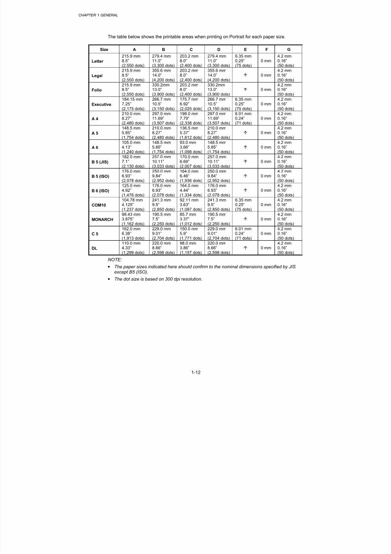
The table below shows the printable areas when printing on Portrait for each paper size.
Size A B C D E F G
Letter
215.9 mm8.5”(2,550 dots)
279.4 mm11.0”(3,300 dots)
203.2 mm8.0”(2,400 dots)
279.4 mm11.0”(3,300 dots)
6.35 mm0.25”(75 dots)
0 mm4.2 mm0.16”(50 dots)
Legal
215.9 mm8.5”(2,550 dots)
355.6 mm14.0”(4,200 dots)
203.2 mm8.0”(2,400 dots)
355.6 mm14.0”(4,200 dots)
0 mm
4.2 mm0.16”(50 dots)
Folio
215.9 mm8.5”(2,550 dots)
330.2mm13.0”(3,900 dots)
203.2 mm8.0”(2,400 dots)
330.2mm13.0”(3,900 dots)
0 mm
4.2 mm0.16”(50 dots)
Executive
184.15 mm7.25”(2,175 dots)
266.7 mm10.5”(3,150 dots)
175.7 mm6.92”(2,025 dots)
266.7 mm10.5”(3,150 dots)
6.35 mm0.25”(75 dots)
0 mm4.2 mm0.16”(50 dots)
A 4
210.0 mm8.27”(2,480 dots)
297.0 mm11.69”(3,507 dots)
198.0 mm7.79”(2,338 dots)
297.0 mm11.69”(3,507 dots)
6.01 mm0.24”(71 dots)
0 mm4.2 mm0.16”(50 dots)
A 5
148.5 mm5.85”
(1,754 dots)
210.0 mm8.27”
(2,480 dots)
136.5 mm5.37”
(1,612 dots)
210.0 mm8.27”
(2,480 dots)
0 mm
4.2 mm0.16”
(50 dots)
A 6
105.0 mm4.13”(1,240 dots)
148.5 mm5.85”(1,754 dots)
93.0 mm3.66”(1,098 dots)
148.5 mm5.85”(1,754 dots)
0 mm
4.2 mm0.16”(50 dots)
B 5 (JIS)
182.0 mm7.1”(2,130 dots)
257.0 mm10.11”(3,033 dots)
170.0 mm6.69”(2,007 dots)
257.0 mm10.11”(3,033 dots)
0 mm
4.2 mm0.16”(50 dots)
B 5 (ISO)
176.0 mm6.93”(2,078 dots)
250.0 mm9.84”(2,952 dots)
164.0 mm6.46”(1,936 dots)
250.0 mm9.84”(2,952 dots)
0 mm
4.2 mm0.16”(50 dots)
B 6 (ISO)
125.0 mm4.92”(1,476 dots)
176.0 mm6.93”(2,078 dots)
164.0 mm4.44”(1,334 dots)
176.0 mm6.93”(2.078 dots)
0 mm
4.2 mm0.16”(50 dots)
COM10
104.78 mm
4.125”(1,237 dots)
241.3 mm
9.5”(2,850 dots)
92.11 mm
3.63”(1,087 dots)
241.3 mm
9.5”(2,850 dots)
6.35 mm
0.25”(75 dots)
0 mm
4.2 mm
0.16”(50 dots)
MONARCH
98.43 mm3.875”(1,162 dots)
190.5 mm7.5”(2,250 dots)
85.7 mm3.37”(1,012 dots)
190.5 mm7.5”(2,250 dots)
0 mm
4.2 mm0.16”(50 dots)
C 5
162.0 mm6.38”(1,913 dots)
229.0 mm9.01”(2,704 dots)
150.0 mm5.9”(1,771 dots)
229.0 mm9.01”(2,704 dots)
6.01 mm0.24”(71 dots)
0 mm4.2 mm0.16”(50 dots)
DL
110.0 mm4.33”(1,299 dots)
220.0 mm8.66”(2,598 dots)
98.0 mm3.86”(1,157 dots)
220.0 mm8.66”(2,598 dots)
0 mm
4.2 mm0.16”(50 dots)
NOTE:
• The paper sizes indicated here should confirm to the nominal dimensions specified by JIS
except B5 (ISO).• The dot size is based on 300 dpi resolution.

8/9/2019 DCP8040 DCP8045D MFC8440 MFC8840D MFC8840DN Manuales Técnicos.pdf
http://slidepdf.com/reader/full/dcp8040-dcp8045d-mfc8440-mfc8840d-mfc8840dn-manuales-tecnicospdf 26/361
MFC-8440/8840D/8840DN, DCP-8040/8045D/8045DNSERVICE MANUAL
1-13

8/9/2019 DCP8040 DCP8045D MFC8440 MFC8840D MFC8840DN Manuales Técnicos.pdf
http://slidepdf.com/reader/full/dcp8040-dcp8045d-mfc8440-mfc8840d-mfc8840dn-manuales-tecnicospdf 27/361
CHAPTER 1 GENERAL
1-14
The table below shows the printable areas when printing on Landscape for each paper size.
Size A B C D E F G
Letter
279.4 mm11.0”(3,300 dots)
215.9 mm8.5”(2,550 dots)
269.3 mm10.6”(3,180 dots)
215.9 mm8.5”(2,550 dots)
5.0 mm0.2”(60 dots)
0 mm4.2 mm0.16”(50 dots)
Legal
355.6 mm14.0”(4,200 dots)
215.9 mm8.5”(2,550 dots)
345.5 mm13.6”(4,080 dots)
215.9 mm8.5”(2,550 dots)
0 mm
4.2 mm0.16”(50 dots)
Folio
330.2mm13.0”(3,900 dots)
215.9 mm8.5”(2,550 dots)
320.0mm12.6”(3,780 dots)
215.9 mm8.5”(2,550 dots)
0 mm
4.2 mm0.16”(50 dots)
Executive
266.7 mm10.5”(3,150 dots)
184.15 mm7.25”(2,175 dots)
256.6 mm10.1”(3,030 dots)
184.15 mm7.25”(2,175 dots)
5.0 mm0.2”(60 dots)
0 mm4.2 mm0.16”(50 dots)
A 4
297.0 mm11.69”(3,507 dots)
210.0 mm8.27”(2,480 dots)
287.0 mm11.2”(3,389 dots)
210.0 mm8.27”(2,480 dots)
4.8 mm0.19”(59 dots)
0 mm4.2 mm0.16”(50 dots)
A 5
210.0 mm8.27”
(2,480 dots)
148.5 mm5.85”
(1,754 dots)
200.0mm7.87”
(2,362 dots)
148.5 mm5.85”
(1,754 dots)
0 mm
4.2 mm0.16”
(50 dots)
A 6
148.5 mm5.85”(1,754 dots)
105.0 mm4.13”(1,240 dots)
138.5 mm5.45”(1,636 dots)
105.0 mm4.13”(1,240 dots)
0 mm
4.2 mm0.16”(50 dots)
B 5 (JIS)
257.0 mm10.11”(3,033 dots)
182.0 mm7.1”(2,130 dots)
247.0 mm9.72”(2,916 dots)
182.0 mm7.1”(2,130 dots)
0 mm
4.2 mm0.16”(50 dots)
B 5 (ISO)
250.0 mm9.84”(2,952 dots)
176.0 mm6.93”(2,078 dots)
240.0 mm9.44”(2,834 dots)
176.0 mm6.93”(2,078 dots)
0 mm
4.2 mm0.16”(50 dots)
B 6 (ISO)
176.0 mm6.93”(2,078 dots)
125.0 mm4.92”(1,476 dots)
166.4 mm6.55”(1,960 dots)
125.0 mm4.92”(1,476 dots)
0 mm
4.2 mm0.16”(50 dots)
COM10
241.3 mm
9.5”(2,850 dots)
104.78 mm
4.125”(1,237 dots)
231.1 mm
9.1”(2,730 dots)
104.78 mm
4.125”(1,237 dots)
5.0 mm
0.2”(60 dots)
0 mm
4.2 mm
0.16”(50 dots)
MONARCH
190.5 mm7.5”(2,250 dots)
98.43 mm3.875”(1,162 dots)
180.4 mm7.1”(2,130 dots)
98.43 mm3.875”(1,162 dots)
0 mm
4.2 mm0.16”(50 dots)
C 5
229 mm9.01”(2,704 dots)
162 mm6.38”(1,913 dots)
219.0 mm8.62”(2,586 dots)
162 mm6.38”(1,913 dots)
4.8 mm0.19”(59 dots)
0 mm4.2 mm0.16”(50 dots)
DL
220 mm8.66”(2,598 dots)
110 mm4.33”(1,299 dots)
210.0 mm8.26”(2,480 dots)
110 mm4.33”(1,299 dots)
0 mm
4.2 mm0.16”(50 dots)
NOTE:
• The paper sizes indicated here should confirm to the nominal dimensions specified by JIS
except B5 (ISO).• The dot size is based on 300 dpi resolution.
2.13.2 PCL6/BR-Script3 emulation
You can not print within 4.2 mm (50dots in 300 dpi mode) on all four sides of the paper.

8/9/2019 DCP8040 DCP8045D MFC8440 MFC8840D MFC8840DN Manuales Técnicos.pdf
http://slidepdf.com/reader/full/dcp8040-dcp8045d-mfc8440-mfc8840d-mfc8840dn-manuales-tecnicospdf 28/361
MFC-8440/8840D/8840DN, DCP-8040/8045D/8045DNSERVICE MANUAL
1-15
2.14 Print Speeds with Various Settings
Print speed of the machine is up to 16/17 ppm when loading A4 or Letter size paper from thepaper tray in the plain paper mode.
Actual print speed varies depending on the media type or paper size as shown in the tablesbelow;
<A4 / Letter size>
Media type setting All models
Transparencies Up to 21/20 ppm
Thin Paper Up to 21/20 ppm
Plain paper, Env.Thin Up to 21/20 ppm
Thick Paper, Envelopes Up to 21/20 ppm
Thicker/Bond Paper, Env.Thick 4 ppm *
<Smaller size than A4 or Letter>
Media type setting All models
Transparency Up to 21/20 ppm
Thin Paper Up to 21/20 ppm
Plain paper, Env.Thin 8 ppm after 5 min. have passed.
Thick Paper, Envelopes 8 ppm after 30 sec. have passed.
Thicker/Bond Paper, Env.Thick 4 ppm *
*The print speed may vary according to conditions, such as paper size and paper tray.
NOTE:
• When a smaller size paper than A4 or Letter is printed, the temperature on both edges ofthe fixing unit is much higher than the temperature on the center of the unit where the paperis fed depending on the setting or model. Therefore, the print speed is slowed in order todecrease the temperature on the edges after the specified time, it is maximum print speedwhen you first start printing.
• Max. speed is 16/17 ppm or more. It varies depending on the paper size.
2.15 Toner Cartridge Weight InformationToner Cartridge Weight (approx weight)
TN3060/TN570 TN3030/TN540
Brand new Toner Cartridge Weight 827.5g 772.5g
Toner Weight at Brand New Toner Cartridge 197.5±2.5g 142.5±2.5g
Toner Cartridge Weight at Toner Near Empty 693.5-698.5g 693.5-698.5g
Remain Toner Weight at Toner Near Empty 80-85g 80-85g
Toner Cartridge Weight at Toner Empty 678.5-683.5g 678.5-683.5g
Remain Toner Weight at Toner Empty 60-70g 60-70g
You can print 500 to 600 pages with 10g toner. *Without yellow protector
*Toner cartridge weight may vary within 2 to 3g depending on the cartridge weight.
8/9/2019 DCP8040 DCP8045D MFC8440 MFC8840D MFC8840DN Manuales Técnicos.pdf
http://slidepdf.com/reader/full/dcp8040-dcp8045d-mfc8440-mfc8840d-mfc8840dn-manuales-tecnicospdf 29/361
CHAPTER 1 GENERAL
1-16
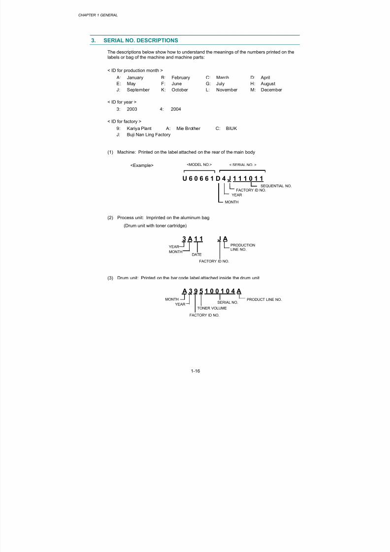
3. SERIAL NO. DESCRIPTIONS
The descriptions below show how to understand the meanings of the numbers printed on thelabels or bag of the machine and machine parts:
< ID for production month >
A: January B: February C: March D: April
E: May F: June G: July H: August
J: September K: October L: November M: December
< ID for year >
3: 2003 4: 2004
< ID for factory >
9: Kariya Plant A: Mie Brother C: BIUK
J: Buji Nan Ling Factory
(1) Machine: Printed on the label attached on the rear of the main body
<Example>
U 6 0 6 6 1 D 4 J 1 1 1 0 1 1
(2) Process unit: Imprinted on the aluminum bag
(Drum unit with toner cartridge)
3 A 1 1 J A
(3) Drum unit: Printed on the bar code label attached inside the drum unit
A 3 9 5 1 0 0 1 0 4 A
YEAR
MONTHDATE
FACTORY ID NO.
YEAR
MONTHSERIAL NO.
<MODEL NO.>
MONTH
YEAR
FACTORY ID NO.SEQUENTIAL NO.
< SERIAL NO. >
FACTORY ID NO.
PRODUCTIONLINE NO.
TONER VOLUME
PRODUCT LINE NO.

8/9/2019 DCP8040 DCP8045D MFC8440 MFC8840D MFC8840DN Manuales Técnicos.pdf
http://slidepdf.com/reader/full/dcp8040-dcp8045d-mfc8440-mfc8840d-mfc8840dn-manuales-tecnicospdf 30/361
MFC-8440/8840D/8840DN, DCP-8040/8045D/8045DNSERVICE MANUAL
1-17
(4) Toner cartridge: Imprinted on the aluminum bag
3 A 3 0 J
Printed on the bar code label attached on the toner cartridge
M 3 9 A 0 0 0 1 9 9 A
(5) Laser unit: On the laser unit
2 8 0 0 1
YEAR
MONTH DATE
FACTORY ID NO.
YEAR
MONTH SERIAL NO.
PRODUCTION LOT NO.
LASER UNIT NO. 8: LJ7516001 Laser Unit ZL2
FACTORY ID NO.
FACTORY ID NO.
CARTRIDGEPRODUCTION INFO.
1: Kariya Plant2: Buji Nan Ling Factory
TONER VOLUME
PRODUCT LINE NO.

8/9/2019 DCP8040 DCP8045D MFC8440 MFC8840D MFC8840DN Manuales Técnicos.pdf
http://slidepdf.com/reader/full/dcp8040-dcp8045d-mfc8440-mfc8840d-mfc8840dn-manuales-tecnicospdf 31/361
MFC-8440/8840D/8840DN, DCP-8040/8045D/8045DNSERVICE MANUAL
2-1
CHAPTER 2 INSTALLATION AND BASIC OPERATION
1. CONDITIONS REQUIRED FOR INSTALLATION
1.1 Power Supply
• The source voltage must stay within ±10% of the rated voltage shown on the rating plate.
• The power cord, including extensions, should not exceed 5 meters (16.5 feet).
• Do no share the same power circuit with other high-power appliances, particularly an airconditioner, copier or shredder. If it is unavoidable that you must use the machine withthese appliances, it is recommended that you use an isolation transformer or a high-frequency noise filter.
• Use a voltage regulator if the power source is not stable.
1.2 Environment• The machine should be installed near a power outlet, which is easily accessible.
• The room temperature is maintained between 10°C and 32.5°C. The relative humidity ismaintained between 20% and 80%.
• The machine should be used in a well ventilated room.
• Place the machine on a flat, horizontal surface.
• Keep the machine clean. Do not place the machine in a dusty place.
• Do not place the machine where the ventilation hole of the machine is blocked. Keepapproximately 100 mm (4 inches) between the ventilation hole and the wall.
• Do not place the machine where it is exposed to direct sunlight. Use a blind or a heavy
curtain to protect the machine from direct sunlight when the machine is unavoidably set upnear a window.
• Do not place the machine near devices that contain magnets or generate magnetic fields.
• Do not subject the machine to strong physical shocks or vibrations.
• Do not expose the machine to open flames or salty or corrosive gasses.
• Do not place objects on top of the machine.
• Do not place the machine near an air conditioner.
• Keep the machine horizontal when carrying.
• Do not cover the slots in the side cover.
8/9/2019 DCP8040 DCP8045D MFC8440 MFC8840D MFC8840DN Manuales Técnicos.pdf
http://slidepdf.com/reader/full/dcp8040-dcp8045d-mfc8440-mfc8840d-mfc8840dn-manuales-tecnicospdf 32/361
CHAPTER 2 INSTALLATION AND BASIC OPERATION
2-2
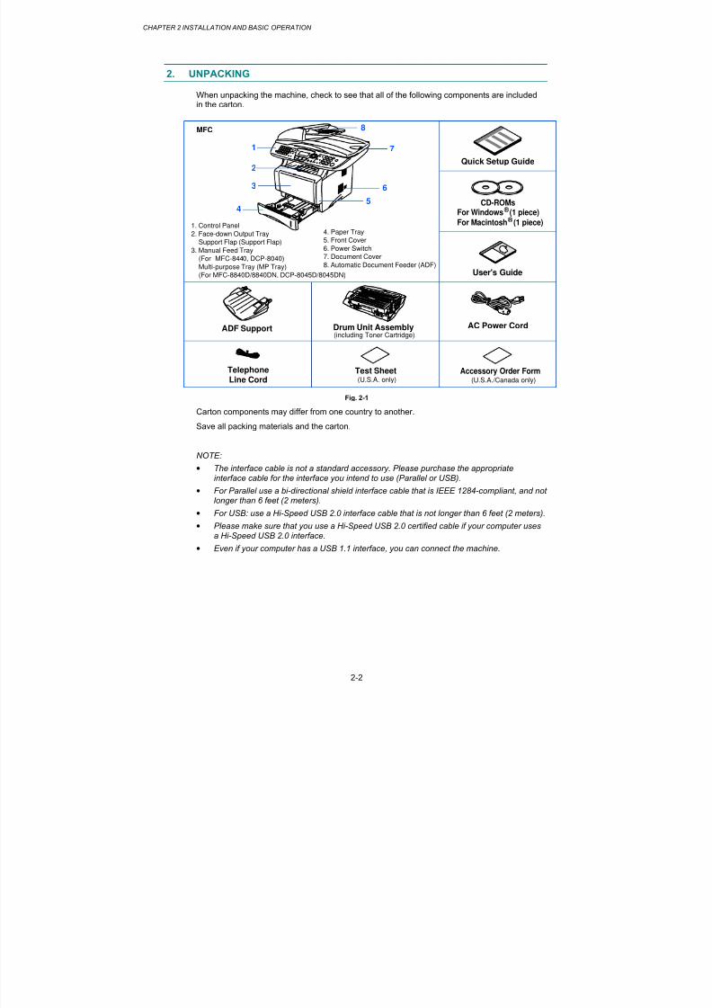
2. UNPACKING
When unpacking the machine, check to see that all of the following components are includedin the carton.
Quick Setup Guide
CD-ROMsFor Windows (1 piece) ®
For Macintosh (1 piece) ®
User's Guide
ADF Support Drum Unit Assembly AC Power Cord
TelephoneLine Cord Test Sheet(U.S.A. only) (U.S.A./Canada only)
(including Toner Cartridge)
Accessory Order Form
4
3
1
1. Control Panel
2. Face-down Output Tray
Support Flap (Support Flap)
3. Manual Feed Tray (For MFC-8440, DCP-8040)
Multi-purpose Tray (MP Tray)
(For MFC-8840D/8840DN, DCP-8045D/8045DN)
4. Paper Tray
5. Front Cover
6. Power Switch7. Document Cover
8. Automatic Document Feeder (ADF)
2
MFC
5
6
7
8
Fig. 2-1
Carton components may differ from one country to another.
Save all packing materials and the carton.
NOTE:
• The interface cable is not a standard accessory. Please purchase the appropriateinterface cable for the interface you intend to use (Parallel or USB).
• For Parallel use a bi-directional shield interface cable that is IEEE 1284-compliant, and not
longer than 6 feet (2 meters).
• For USB: use a Hi-Speed USB 2.0 interface cable that is not longer than 6 feet (2 meters).
• Please make sure that you use a Hi-Speed USB 2.0 certified cable if your computer usesa Hi-Speed USB 2.0 interface.
• Even if your computer has a USB 1.1 interface, you can connect the machine.

8/9/2019 DCP8040 DCP8045D MFC8440 MFC8840D MFC8840DN Manuales Técnicos.pdf
http://slidepdf.com/reader/full/dcp8040-dcp8045d-mfc8440-mfc8840d-mfc8840dn-manuales-tecnicospdf 33/361

8/9/2019 DCP8040 DCP8045D MFC8440 MFC8840D MFC8840DN Manuales Técnicos.pdf
http://slidepdf.com/reader/full/dcp8040-dcp8045d-mfc8440-mfc8840d-mfc8840dn-manuales-tecnicospdf 34/361
CHAPTER 2 INSTALLATION AND BASIC OPERATION
2-4
3.1.1 Install the Automatic Document Feed (ADF) support
(1) Open the ADF cover.
Fig. 2-2
Fig. 2-3
(2) Slide ADF support into the groove on ADF.
Fig. 2-4
ADF cover

8/9/2019 DCP8040 DCP8045D MFC8440 MFC8840D MFC8840DN Manuales Técnicos.pdf
http://slidepdf.com/reader/full/dcp8040-dcp8045d-mfc8440-mfc8840d-mfc8840dn-manuales-tecnicospdf 35/361
MFC-8440/8840D/8840DN, DCP-8040/8045D/8045DNSERVICE MANUAL
2-5
(3) Close the ADF cover.
Fig. 2-5
3.1.2 Install the drum unit assembly
(1) Open the front cover by pressing the front cover release button.
(2) Unpack the drum unit assembly. Remove the protective part.
(3) Rock it from side to side several times to distribute the toner evenly inside the assembly.
Fig. 2-6
(4) Push the drum unit assembly into the machine (until it snaps into place).
Fig. 2-7
(5) Close the front cover of the machine.
8/9/2019 DCP8040 DCP8045D MFC8440 MFC8840D MFC8840DN Manuales Técnicos.pdf
http://slidepdf.com/reader/full/dcp8040-dcp8045d-mfc8440-mfc8840d-mfc8840dn-manuales-tecnicospdf 36/361
CHAPTER 2 INSTALLATION AND BASIC OPERATION
2-6
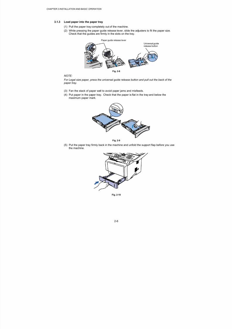
3.1.3 Load paper into the paper tray
(1) Pull the paper tray completely out of the machine.
(2) While pressing the paper guide release lever, slide the adjusters to fit the paper size.Check that the guides are firmly in the slots on the tray.
Fig. 2-8
NOTE:
For Legal size paper, press the universal guide release button and pull out the back of the paper tray.
(3) Fan the stack of paper well to avoid paper jams and misfeeds.
(4) Put paper in the paper tray. Check that the paper is flat in the tray and below themaximum paper mark.
Fig. 2-9
(5) Put the paper tray firmly back in the machine and unfold the support flap before you usethe machine.
Fig. 2-10
Universal guiderelease button
Paper guide release lever

8/9/2019 DCP8040 DCP8045D MFC8440 MFC8840D MFC8840DN Manuales Técnicos.pdf
http://slidepdf.com/reader/full/dcp8040-dcp8045d-mfc8440-mfc8840d-mfc8840dn-manuales-tecnicospdf 37/361
MFC-8440/8840D/8840DN, DCP-8040/8045D/8045DNSERVICE MANUAL
2-7
3.1.4 Release the scanner lock
(1) Push the lever up to unlock the scanner. (Refer to Fig.2-11.)
Fig. 2-11
Scanner lock lever

8/9/2019 DCP8040 DCP8045D MFC8440 MFC8840D MFC8840DN Manuales Técnicos.pdf
http://slidepdf.com/reader/full/dcp8040-dcp8045d-mfc8440-mfc8840d-mfc8840dn-manuales-tecnicospdf 38/361
CHAPTER 2 INSTALLATION AND BASIC OPERATION
2-8
3.2 Installing the Driver & Software
3.2.1 For USB Interface Cable Users (For Windows ®
98/98SE/Me/2000 Professional/XP)
(1) Switch off and unplug the machine from the AC outlet and disconnect it from yourcomputer, if you already connected an interface cable.
(2) Turn on your computer.(For Windows
® 2000 Professional/XP, you must be logged on as the administrator.)
(3) Insert the supplied CD-ROM for the operating system you are using into your CD-ROMdrive. If the model name screen appears, select your machine. If the language screenappears, select your language..
(4) The CD-ROM main menu will appear.
Click Install Software.
NOTE:
If this window does not appear, use Windows® Explore to run the setup.exe program from the
root directory of the Brother CD-ROM.
(5) Click MFL-Pro Suite in Main Application.
NOTE:
• MFL-Pro Suite includes Printer Driver, Scanner Driver, ScanSoft ® PaperPort
® , ScanSoft
®
Text Bridge® , PC-FAX software, Remote Setup and True Type fonts.
• PaperPort ® is a document management application for viewing scanned documents.
• ScanSoft ® TextBridge
® , which is integrated into PaperPort
® , is an OCR application that
converts an image into text and inserts it into your default word processor.
(6) Click Install.
NOTE:
• If you see the following screen, click OK to install the Windows® updates. After the
updates are installed your PC may restart.
• If it does the installation will automatically continue.
• If the installation does not continue automatically, please open the installer menu again by
double-clicking the setup.exe program from the root directory of the Brother CD-ROM, andcontinue from Step (4).
(7) When the PaperPort® 8.0 SE Setup window is displayed, click Next.
(8) After reading and accepting the ScanSoft License Agreement, enter your user
information and click Next.
(9) Select Typical and click Next.
(10) Click Install and PaperPort® will start installing on your computer.
(11) When the ScanSoft Registration screen is displayed, make your selection and follow theon-screen instructions.
(12) Click Finish to complete installation.

8/9/2019 DCP8040 DCP8045D MFC8440 MFC8840D MFC8840DN Manuales Técnicos.pdf
http://slidepdf.com/reader/full/dcp8040-dcp8045d-mfc8440-mfc8840d-mfc8840dn-manuales-tecnicospdf 39/361
MFC-8440/8840D/8840DN, DCP-8040/8045D/8045DNSERVICE MANUAL
2-9
(13) When the Brother MFL-Pro Suite Installation window appears, click Next.
NOTE:
• If an error message appears during the installation process, or if you have previouslyinstalled the MFL-Pro Suite, you will first have to uninstall it.
•From the Start menu, select Programs, Brothe r, Bro ther MFL-Pro Suite , Uninsta l l , andthen follow the instructions on the screen.
(14) When the Brother Software License Agreement window appears, click Yes.
(15) Select Local Interface, and then click Next.
(16) Select Standard, and then click Next. The application files will be copied and installed toyour computer.
< For Windows® 98/98SE/Me Users Only >
Make sure that you followed the instructions in (1) to (16) on pages 2-8 to 2-9.
(17) When this screen appears, connect the USB interface cable to your PC, and thenconnect it to the machine.
Turn on the machine by plugging in the power cord. Turn the power switch on.
It will take a few seconds for the installation screen to appear.
The installation of the Brother drivers will automatically start. Follow the instructions onthe screen.
(18) Select BRUSB: USB Printer Port, and then click Next.
(19) Accept the default Printer name by selecting Yes, and then click Next.
(20) Select Yes (recommended), and then click Finish. A test page will be printed so youcan check the print quality.
(21) If the test page is printed correctly, click Yes. If you click No, follow the prompts on thescreen to correct the problem.
(22) The README.WRI file will be displayed. Please read this file for troubleshootinginformation and then close the file to continue installation.
(23) Click Finish to restart your computer.
(24) After the computer restarts, click Yes to have the Control Center load each time
Windows®
is started. The Control Center will appear as an icon in the task tray.If you click No the Scan keys on the machine will be disabled.
NOTE:
Even if you select NO , later you will be able to launch the Brother Control Center to use the
Scan to key by double clicking the Smart UI icon on the desktop. This loads the BrotherControl Center to the task tray. See AutoLoad the Brother Control Center, Chapter 15 in theDocumentation (User’s Guide) located on the CD-ROM.
OK:
The Broth er PC-FAX, Printer and Scann er drivers have been instal led and the
insta l lat ion is no w complete.

8/9/2019 DCP8040 DCP8045D MFC8440 MFC8840D MFC8840DN Manuales Técnicos.pdf
http://slidepdf.com/reader/full/dcp8040-dcp8045d-mfc8440-mfc8840d-mfc8840dn-manuales-tecnicospdf 40/361
CHAPTER 2 INSTALLATION AND BASIC OPERATION
2-10
< For Windows® 2000 Professional Users Only >
Make sure that you followed the instructions in (1) to (16) on pages 2-8 to 2-9.
(17) When this screen appears, connect the USB interface cable to your PC, and then
connect it to the machine.Turn on the machine by plugging in the power cord. Turn the power switch on.
It will take a few seconds for the installation screen to appear.
The installation of the Brother drivers will automatically start. Follow the instructions onthe screen.
(18) If the Digital Signature Not Found dialog boxes appear, click Yes to install the driver.
(19) The README.WRI file will be displayed.
Please read this file for troubleshooting information and then close the file to continueinstallation.
(20) Click Finish to restart your computer.
(21) After the computer restarts, click Yes to have the Control Center load each timeWindows
® is started. The Control Center will appear as an icon in the task tray.
If you click No the Scan keys on the machine will be disabled.
NOTE:
Even if you select NO , later you will be able to launch the Brother Control Center to use the
Scan to key by double clicking the Smart UI icon on the desktop. This loads the BrotherControl Center to the task tray. See AutoLoad the Brother Control Center, Chapter 15 in theDocumentation (User’s Guide) located on the CD-ROM.
OK:
This com pletes the insta l lat ion of the Window s ® Logo Tested (WHQL) printer driv er and
the Broth er PC-FAX and scanner drivers.
Bro ther also off ers a Native Driver on t he CD-ROM. The Bro ther Native Driver offers
some features that are not avai lab le with the Window s ® Logo Tested Driver. To instal l
the Bro ther Native driver proc eed to step (22).
Brother Native driver Installation
(22) Click Start and select Settings and then Pointers. Click on Add a printer and the AddPrinter Wizard will start.
When this screen appears, click Next.
(23) Un-check the Automatically detect and install my Plug and Play printer selection
and then click Next.
(24) Select USBXXX from the pull down window for the Printer Port Selection and then click
Next.
(25) Click on Have Disk.
(26) Browse the CD-ROM for the W2K folder.
Highlight the W2K folder and click Open.
Highlight the Addprt folder and click Open.
(27) Click Open.

8/9/2019 DCP8040 DCP8045D MFC8440 MFC8840D MFC8840DN Manuales Técnicos.pdf
http://slidepdf.com/reader/full/dcp8040-dcp8045d-mfc8440-mfc8840d-mfc8840dn-manuales-tecnicospdf 41/361
MFC-8440/8840D/8840DN, DCP-8040/8045D/8045DNSERVICE MANUAL
2-11
(28) Make sure X:\W2K\Addprt is displayed in the window and click OK (X:\ is the driveletter of your CD-ROM).
(29) Highlight the model you are installing from the list of machines and click Next.
(30) The model you are installing will be listed in the window. Select Yes or No if you wantthis driver to be your default printer.
(31) Select Do not share this printer and Next.
(32) Select Yes and Next to print a test page.
(33) When this screen appears, click Finish.
(34) If the Digital Signature Not Found dialog box appears, click Yes.
(35) If the test page printed, click OK.
NOTE:
• There will be two Brother printer drivers listed in the Printers selection.
• The driver with "Printer" after the model name (ex. Brother MFC-8840D Printer) is the
Brother Native Driver.
OK:
The Broth er Native Drivers have been instal led and the instal lat ion is no w comp lete.
< For Windows® XP Users Only >
Make sure that you followed the instructions in (1) to (16) on pages 2-8 to 2-9.
(17) When this screen appears, connect the USB interface cable to your PC, and thenconnect it to the machine.
Turn on the machine by plugging in the power cord. Turn the power switch on.
It will take a few seconds for the installation screen to appear.
The installation of the Brother drivers will automatically start. The screen appears oneafter another, please wait for a while.
(18) The README.WRI file will be displayed.
Please read this file for troubleshooting information and then close the file to continueinstallation.
(19) Click Finish to restart your computer.
OK:
This com pletes the insta l lat ion of the Window s ® Logo Tested (WHQL) printer driv er and
the Broth er PC-FAX and scanner drivers.
Bro ther also offers a Native Driver on the CD-ROM. The Broth er Native Driver offers
some features that are not avai lab le with the Window s ® Logo Tested Driver. To instal l
the Bro ther Native driver proc eed to step (20).

8/9/2019 DCP8040 DCP8045D MFC8440 MFC8840D MFC8840DN Manuales Técnicos.pdf
http://slidepdf.com/reader/full/dcp8040-dcp8045d-mfc8440-mfc8840d-mfc8840dn-manuales-tecnicospdf 42/361
CHAPTER 2 INSTALLATION AND BASIC OPERATION
2-12
Brother Native driver Installation
(20) Click Start and select Printers and Faxes.
Click on Add a printer and the Add Printer Wizard will start.
When this screen appears, click Next.
(21) Un-check the Automatically detect and install my Plug and Play printer selection
and then click Next.
(22) Select USBXXX from the pull down window for the Printer Port Selection and then click
Next.
(23) Click on Have Disk.
(24) Browse the CD-ROM for the WXP folder.
Highlight the WXP folder and click Open.
Highlight the Addprt folder and click Open.
(25) Click Open.
(26) Make sure X:\WXP\Addprt is displayed in the window and click OK (X:\ is the drive your
CD-ROM).
(27) Highlight the model you are installing from the list of machines and click Next.
(28) The model you are installing will be listed in the window. Select Yes or No if you wantthis driver to be your default printer.
(29) Select Do not share this printer and Next.
(30) Select Yes and Next to print a test page.
(31) When this screen appears, click Finish.
(32) When the Windows Logo testing screen appears, click Continue Anyway.
NOTE:
• There will be two Brother printer drivers listed in the “Printers” selection.
• The driver with Printer after the model name (ex. Brother MFC-8840D Printer) is theBrother Native Driver.
OK:
The Broth er Native Drivers have been instal led and the instal lat ion is no w comp lete.

8/9/2019 DCP8040 DCP8045D MFC8440 MFC8840D MFC8840DN Manuales Técnicos.pdf
http://slidepdf.com/reader/full/dcp8040-dcp8045d-mfc8440-mfc8840d-mfc8840dn-manuales-tecnicospdf 43/361
MFC-8440/8840D/8840DN, DCP-8040/8045D/8045DNSERVICE MANUAL
2-13
3.2.2 For Parallel Interface Cable Users (For Windows ®
95/98/98SE/Me/2000 Professional/XP)
(1) Switch off and unplug the machine from the AC outlet and disconnect it from yourcomputer, if you already connected an interface cable.
(2) Turn on your computer.
(For Windows® 2000 Professional/XP, you must be logged on as the administrator.)
(3) Insert the supplied CD-ROM for the operating system you are using into your CD-ROMdrive. If the model name screen appears, select your machine. If the language screenappears, select your language.
(4) The CD-ROM main menu will appear.
Click Install Software.
NOTE:
If this window does not appear, use Windows® Explore to run the setup.exe program from the
root directory of the Brother CD-ROM.
(5) Click MFL-Pro Suite in Main Application.
NOTE:
• MFL-Pro Suite includes Printer Driver, Scanner Driver, ScanSoft ® PaperPort
® ,
ScanSoft ® Text Bridge
® , PC-FAX software, Remote Setup and True Type fonts.
PaperPort ® is a document management application for viewing scanned documents.
• ScanSoft ® TextBridge
® , which is integrated into PaperPort
® , is an OCR application that
converts an image into text and inserts it into your default word processor.
(6) Click Install.
NOTE:
•
If you see the following screen, click OK to install the Windows
®
updates. After theupdates are installed your PC may restart.
• If it does the installation will automatically continue.
• If the installation does not continue automatically, please open the installer menu again by
double-clicking the setup.exe program from the root directory of the Brother CD-ROM,and continue from step (4).
(7) When the PaperPort® 8.0 SE Setup window is displayed, click Next.
(8) After reading and accepting the ScanSoft License Agreement, enter your user
information and click Next.
(9) Select Typical and click Next.
(10) Click Install and PaperPort ® will start installing on your computer.
(11) When the ScanSoft Registration screen is displayed, make your selection and follow theon- screen instructions.
(12) Click Finish to complete installation.
(13) When the Brother MFL-Pro Suite Installation window appears, click Next.
NOTE:
If an error message appears during the installation process, or if you have previously installed
the MFL-Pro Suite, you will first have to uninstall it. From the Start menu, select Programs,
Bro the r, Bro ther MFL-Pro Suite , Uninsta l l , and then follow the instructions on the screen.

8/9/2019 DCP8040 DCP8045D MFC8440 MFC8840D MFC8840DN Manuales Técnicos.pdf
http://slidepdf.com/reader/full/dcp8040-dcp8045d-mfc8440-mfc8840d-mfc8840dn-manuales-tecnicospdf 44/361
CHAPTER 2 INSTALLATION AND BASIC OPERATION
2-14
(14) When the Brother Software License Agreement window appears, click Yes.
(15) Select Local Interface, and then click Next.
(16) Select Standard, and then click Next. The application files will be copied to yourcomputer.
< For Windows® 95/98/98SE/Me Users Only >
Make sure that you followed the instructions in (1) to (16) on pages 2-13 to 2-14.
(17) When this screen appears, connect the parallel interface cable to your PC, and thenconnect it to the machine.
Turn on the machine by plugging in the power cord. Turn the power switch on.
(18) Click Next.
(19) The README.WRI file will be displayed.
Please read this file for troubleshooting information and then close the file to continueinstallation.
(20) Click Finish to restart your computer.
(21) After the computer restarts, the installation of the Brother drivers will automatically start.
Follow the instructions on the screen.
(22) Click Yes to have the Brother MFL-Pro Control Center load each time Windows® is
started. The Control Center will appear as an icon in the task tray.
If you click No the Scan keys on the machine will be disabled.
NOTE:Even if you select NO , later you will be able to launch the Brother Control Center to use the
Scan to key by double clicking the Smart UI icon on the desktop. This loads the BrotherControl Center to the task tray. See AutoLoad the Brother Control Center, Chapter 15 in theDocumentation (User’s Guide) located on the CD-ROM.
OK:
The Broth er PC-FAX, Printer and Scann er drivers have been instal led and the
insta l lat ion is now com plete.
< For Windows® 2000 Professional Users Only >
Make sure that you followed the instructions in (1) to (16) on pages 2-13 to 2-14.
(17) When this screen appears, connect the parallel interface cable to your PC, and thenconnect it to the machine.
Turn on the machine by plugging in the power cord. Turn the power switch on.
(18) Click the Next.
(19) The README.WRI file will be displayed.
Please read this file for troubleshooting information and then close the file to continueinstallation.

8/9/2019 DCP8040 DCP8045D MFC8440 MFC8840D MFC8840DN Manuales Técnicos.pdf
http://slidepdf.com/reader/full/dcp8040-dcp8045d-mfc8440-mfc8840d-mfc8840dn-manuales-tecnicospdf 45/361
MFC-8440/8840D/8840DN, DCP-8040/8045D/8045DNSERVICE MANUAL
2-15
(20) Click Finish to restart your computer.
(21) After the computer restarts, the installation of the Brother drivers will automatically start.
Follow the instructions on the screen.
(22) If the Digital Signature Not Found dialog boxes appear, click Yes to install the driver.
(23) Click Yes to have the Control Center loaded each time Windows®
is started. The ControlCenter will appear as an icon in the task tray.
If you click No the Scan keys on the machine will be disabled.
NOTE:
Even if you select NO , later you will be able to launch the Brother Control Center to use the
Scan to key by double clicking the Smart UI icon on the desktop. This loads the BrotherControl Center to the task tray. See AutoLoad the Brother Control Center, Chapter 15 in theDcumentation (User’s Guide) located on the CD-ROM.
OK:
This com pletes the insta l lat ion of the Window s® Logo Tested (WHQL) printer driver and
the Broth er PC-FAX and scanner drivers.
Bro ther also off ers a Native Driver on t he CD-ROM. The Bro ther Native Driver offers
some features that are not avai lab le with the Window s® Logo Tested Driver. To instal l
the Bro ther Native driver proc eed to step (21).
Brother Native driver Installation
(24) Click Start and select Settings and then Pointers. Click on Add a printer and the AddPrinter Wizard will start.
When this screen appears, click Next.
(25) Un-check the Automatically detect and install my Plug and Play printer selection and
then click Next.
(26) Select BMFC (Brother MFL Port) from the pull down window for the Printer Port
Selection and then click Next.
(27) Click on Have Disk.
(28) Browse the CD-ROM for the W2K folder.
Highlight the W2K folder and click Open.
Highlight the Addprt folder and click Open.
(29) Click Open.
(30) Make sure X:\W2K\Addprt is displayed in the window and click OK (X:\ is the drive letter
of your CD-ROM).
(31) Highlight the model you are installing from the list of machines and click Next.
(32) The model you are installing will be listed in the window. Select Yes or No if you want thisdriver to be your default printer.
(33) Select Do not share this printer and Next.
(34) Select Yes and Next to print a test page.
(35) When this screen appears, click Finish.
(36) If the Digital Signature Not Found dialog box appears, click Yes.
(37) If the test page printed, click OK.

8/9/2019 DCP8040 DCP8045D MFC8440 MFC8840D MFC8840DN Manuales Técnicos.pdf
http://slidepdf.com/reader/full/dcp8040-dcp8045d-mfc8440-mfc8840d-mfc8840dn-manuales-tecnicospdf 46/361
CHAPTER 2 INSTALLATION AND BASIC OPERATION
2-16
NOTE:
• There will be two Brother printer drivers listed in the Printers selection.
• The driver with "Printer" after the model name (ex. Brother MFC-8840D Printer) is theBrother Native Driver.
OK:
The Broth er Native Drivers have been instal led and the instal lat ion is no w comp lete.
< For Windows® XP Users Only >
Make sure that you followed the instructions in (1) to (16) on pages 2-13 to 2-14.
(17) When this screen appears, connect the parallel interface cable to your PC, and then
connect it to the machine.Turn on the machine by plugging in the power cord. Turn the power switch on.
The installation of the Brother drivers will automatically start.
The screen appears one after another, please wait for a while.
(18) The README.WRI file will be displayed.
Please read this file for troubleshooting information and then close the file to continueinstallation.
(19) When the following screen appears, click Finish and wait as the PC restarts Windowsand continues the installation.
OK:
This com pletes the insta l lat ion of the Window s ® Logo Tested (WHQL) printer driv er and
the Broth er PC-FAX and scanner drivers.
Bro ther also off ers a Native Driver on t he CD-ROM. The Bro ther Native Driver offers
some features that are not avai lab le with the Window s ® Logo Tested Driver. To instal l
the Bro ther Native driver proc eed to step (20).
Brother Native driver Installation
(20) Click Start and select Printers and Faxes.
Click on Add a printer and the Add Printer Wizard will start.
When this screen appears, click Next.
(21) Un-check the Automatically detect and install my Plug and Play printer selection and
then click Next.
(22) Select BMFC (Brother MFL Port) from the pull down window for the Printer Port
Selection and then click Next.
(23) Click on Have Disk.
(24) Browse the CD-ROM for the WXP folder.
Highlight the WXP folder and click Open.
Highlight the Addprt folder and click Open.
(25) Click Open.
(26) Make sure X:\WXP\Addprt is displayed in the window and click OK (X:\ is the drive letterof your CD-ROM).

8/9/2019 DCP8040 DCP8045D MFC8440 MFC8840D MFC8840DN Manuales Técnicos.pdf
http://slidepdf.com/reader/full/dcp8040-dcp8045d-mfc8440-mfc8840d-mfc8840dn-manuales-tecnicospdf 47/361
MFC-8440/8840D/8840DN, DCP-8040/8045D/8045DNSERVICE MANUAL
2-17
(27) Highlight the model you are installing from the list of machines and click Next.
(28) The model you are installing will be listed in the window. Select Yes or No if you want thisdriver to be your default printer.
(29) Select Do not share this printer and Next.
(30) Select Yes and Next to print a test page.
(31) When this screen appears, click Finish.
(32) When the Windows Logo testing screen appears, click Continue Anyway.
NOTE:
• There will be two Brother printer drivers listed in the Printers selection.
• The driver with "Printer" after the model name (ex. Brother MFC-8840D Printer) is theBrother Native Driver.
OK:
The Broth er Native Drivers have been instal led and the instal lat ion is no w comp lete.

8/9/2019 DCP8040 DCP8045D MFC8440 MFC8840D MFC8840DN Manuales Técnicos.pdf
http://slidepdf.com/reader/full/dcp8040-dcp8045d-mfc8440-mfc8840d-mfc8840dn-manuales-tecnicospdf 48/361
CHAPTER 2 INSTALLATION AND BASIC OPERATION
2-18
3.2.3 For Windows NT ®
Workstation Version 4.0 Users
(1) Turn on your computer.
You must be logged on as the Administrator.
(2) Connect the parallel interface cable to your computer, and then connect it to the machine.
(3) Make sure you turn on the machine by plugging in the power cord, and turning the powerswitch on.
(4) Insert the Supplied CD-ROM for the operating system you are using into your CD-ROMdrive. If the model name screen appears, select your machine. If the language screenappears, select your language.
(5) The CD-ROM main menu will appear.
Click Install Software.
NOTE:
If this window does not appear, use Windows® Explore to run the setup.exe program from the
root directory of the Brother CD-ROM.
(6) Click MFL-Pro Suite in Main Application.
NOTE:
• MFL-Pro Suite includes Printer Driver, Scanner Driver, ScanSoft ® PaperPort
® ScanSoft
® ,
Text Bridge® , PC-FAX software, Remote Setup and True Type fonts.
• PaperPort ® is a document management application for viewing scanned documents.
• ScanSoft ® TextBridge
® , which is integrated into PaperPort
® , is an OCR application that
converts an image into text and inserts it into your default word processor.
(7) Click Install.
NOTE:
• If you see the following screen, click OK to install the Windows® updates. After the updates
are installed your PC may restart.
• If it does the installation will automatically continue.
• If the installation does not continue automatically, please open the installer menu again by
double-clicking the setup.exe program on the Brother CD-ROM, and continue from Step(5).
(8) When the PaperPort® 8.0 SE Setup window is displayed, click Next.
(9) After reading and accepting the ScanSoft License Agreement, enter your user
information and click Next.
(10) Select Typical and click Next.
(11) Click Install and PaperPort® will start installing on your computer.
(12) When the ScanSoft Registration screen is displayed, make your selection and follow theon- screen instructions.
(13) Click Finish to complete installation.
(14) When the Brother MFL-Pro Suite Installation window appears, click Next.
NOTE:
If an error message appears during the installation process, or you have previously installed
MFL-Pro Suite, you will first have to uninstall it. From the Start menu, select Programs ,
Brother , Bro ther MFL-Pro Suite, Uninstal l , and then follow the instructions on the screen.

8/9/2019 DCP8040 DCP8045D MFC8440 MFC8840D MFC8840DN Manuales Técnicos.pdf
http://slidepdf.com/reader/full/dcp8040-dcp8045d-mfc8440-mfc8840d-mfc8840dn-manuales-tecnicospdf 49/361
MFC-8440/8840D/8840DN, DCP-8040/8045D/8045DNSERVICE MANUAL
2-19
(15) When the Brother Software License Agreement window appears, click Yes. If you agreeto it and go to next screen.
(16) Select Local Interface, and then click Next.
(17) When the Setup Type window appears, select Standard, and then click Next.
(18) The README.WRI file will be displayed.Please read this file for troubleshooting information and then close the file to continueinstallation.
(19) Click Finish restart your computer.
(20) After the computer restarts, click Yes to have the Control Center load each timeWindows
® is started. The Control Center will appear as an icon in the task tray.
If you click No the Scan keys on the machine will be disabled.
NOTE:
Even if you select NO , later you will be able to launch the Brother Control Center to use the
Scan to key by double clicking the Smart UI icon on the desktop. This loads the Brother
Control Center to the task tray. See AutoLoad the Brother Control Center, Chapter 15 in theDocumentation (User’s Guide) located on the CD-ROM.
OK:
The Broth er PC-FAX, Printer and Scann er drivers have been instal led and the
insta l lat ion is now com plete.

8/9/2019 DCP8040 DCP8045D MFC8440 MFC8840D MFC8840DN Manuales Técnicos.pdf
http://slidepdf.com/reader/full/dcp8040-dcp8045d-mfc8440-mfc8840d-mfc8840dn-manuales-tecnicospdf 50/361
CHAPTER 2 INSTALLATION AND BASIC OPERATION
2-20
3.2.4 For Network Interface Cable Users (For Windows ®
95/98/98SE/Me/NT/2000
Professional/XP)
(1) Connect the network cable to the machine, and then connect it to a free port on your hub.
Turn on the machine by plugging in the power cord. Turn the power switch on.
(2) Turn on your computer.
(For Windows® 2000 Professional/XP, you must be logged on as the administrator.)
(3) Insert the supplied CD-ROM for the operating system you are using into your CD-ROMdrive. If the model name screen appears, select your machine. If the language screenappears, select your language.
(4) The CD-ROM main menu will appear.
Click Install Software.
NOTE:
If this window does not appear, use Windows® Explore to run the setup.exe program from the
root directory of the Brother CD-ROM.
(5) Click MFL-Pro Suite in Main Application.
NOTE:
• MFL-Pro Suite includes Printer Driver, Scanner Driver, ScanSoft ® PaperPort
® ,
ScanSoft ® Text Bridge
® , PC-FAX software and True Type fonts.
• PaperPort ® is a document management application for viewing scanned documents.
• ScanSoft ® TextBridge
® , which is integrated into PaperPort
® , is an OCR application that
converts an image into text and inserts it into your default word processor.
(6) Click Install.
NOTE:
• If you see the following screen, click OK to install the Windows® updates. After the updates
are installed your PC may restart.
• If it does the installation will automatically continue.
• If the installation does not continue automatically, please open the installer menu again by
double-clicking the setup.exe program from the root directory of the Brother CD-ROM,and continue from Step (4).
(7) When the PaperPort® 8.0 SE Setup window is displayed, click Next.
(8) After reading and accepting the ScanSoft License Agreement, enter your user
information and click Next.
(9) Select Typical and click Next.
(10) Click Install and PaperPort® will start installing on your computer.
(11) When the ScanSoft Registration screen is displayed, make your selection and follow theon- screen instructions.
(12) Click Finish to complete installation.
(13) When the Brother MFL-Pro Suite Installation window appears, click Next.
NOTE:
If an error message appears during the installation process, or if you have previously installed
the MFL-Pro Suite, you will first have to uninstall it. From the Start menu, select Programs,
Brother , Bro ther MFL-Pro Suite , Uninsta l l , and then follow the instructions on the screen.
8/9/2019 DCP8040 DCP8045D MFC8440 MFC8840D MFC8840DN Manuales Técnicos.pdf
http://slidepdf.com/reader/full/dcp8040-dcp8045d-mfc8440-mfc8840d-mfc8840dn-manuales-tecnicospdf 51/361
MFC-8440/8840D/8840DN, DCP-8040/8045D/8045DNSERVICE MANUAL
2-21
(14) When the Brother Software License Agreement window appears, click Yes.
(15) Select Network Interface, and then click Next.
(16) Select Standard, and then click Next.
The application files will be copied to your computer.
(17) Select Search from a list of available devices, and then click Next.
NOTE:
If you see the following screen, click OK .
(18) If the machine is un-configured for your network:
Select the un-configured device from the list and then click Next. Go to (19)
If the machine is configured for your network:
Select the machine from the list and then click Next. Go to (22)
(19) Click Configure IP Address.
(20) Enter the proper IP Address information for your network, and then click OK.(e.g. Enter 10.134.43.79 for IP Address)
(21) Click Next.
NOTE:
See the For Administrator section of this guide or the NC-9100h User's Guide located on theCD-ROM for more network configuration information.
Windows® 98/Me/2000/XP Users Go to (22)
Windows® 95/NT Users Go to (24)
(22) Select yes and then click Next.
(23) Click Next or enter the name you want displayed on the LCD for your PC and then click
Next. The default name is the name of your PC .
NOTE:
You can avoid receiving unwanted documents by setting a 4-digit PIN Number.
For Windows® 98/Me/2000/XP Users Only
Please wait for the window to open.
(24) Click Finish restart your computer.
Windows ® 95/98/98SE/Me/NT/2000 Users follow step (25).
NOTE:
The Network Scanning feature is not supported in Windows® 95 or NT.
OK:
For Windows ® XP Users Only
The Broth er PC-FAX, Printer and Scann er drivers have been instal led and the
insta l lat ion is now com plete.

8/9/2019 DCP8040 DCP8045D MFC8440 MFC8840D MFC8840DN Manuales Técnicos.pdf
http://slidepdf.com/reader/full/dcp8040-dcp8045d-mfc8440-mfc8840d-mfc8840dn-manuales-tecnicospdf 52/361
CHAPTER 2 INSTALLATION AND BASIC OPERATION
2-22
(25) After the computer restarts, click Yes to have the Control Center load each timeWindows
® is started. The Control Center will appear as an icon in the task tray.
If you click No the Scan keys on the machine will be disabled.
NOTE:
Even if you select NO , later you will be able to launch the Brother Control Center to use theScan to key by double clicking the Smart UI icon on the desktop. This loads the BrotherControl Center to the task tray. See AutoLoad the Brother Control Center, Chapter 15 in theDocumentation (User’s Guide) located on the CD-ROM.
OK:
For Windows ® 98/Me/2000 Users
The Broth er PC-FAX, Printer and Scann er drivers have been instal led and the
insta l lat ion is now com plete.
For Windows ® 95/NT Users
The Broth er PC-FAX and Printer drivers have been instal led and the instal lat ion is now
complete.
8/9/2019 DCP8040 DCP8045D MFC8440 MFC8840D MFC8840DN Manuales Técnicos.pdf
http://slidepdf.com/reader/full/dcp8040-dcp8045d-mfc8440-mfc8840d-mfc8840dn-manuales-tecnicospdf 53/361
MFC-8440/8840D/8840DN, DCP-8040/8045D/8045DNSERVICE MANUAL
2-23
3.2.5 For USB Interface Cable Users (For Mac ®
OS 8.6 to 9.2 Users)
(1) Switch off and unplug the machine from the AC outlet and disconnect it from yourMacintosh if you already connected an interface cable.
(2) Turn on your Macintosh®.
(3) Insert the supplied CD-ROM for the operating system you are using into your CD-ROMdrive.
(4) Double-click the Start Here! icon to install the printer, scanner and PC-FAX Senddrivers. If the language screen appears, select your language.
(5) Click MFL-Pro Suite for your country to install.
(6) After the installation is completed, restart your Macintosh®.
(7) Connect the USB interface cable to your Macintosh®, and then connect it to the machine.
Caut ion
Do not co nnect the machine to a USB por t on a keyboard or a non powered USB hub.
(8) Turn on the machine by plugging in the power cord. Turn the power switch on.
(9) From the Apple® menu, open the Chooser .
(10) Click the Brother Laser icon you installed.
On the right side of the Chooser , select the printer to which you want to print.
Close the Chooser .
OK:
The Brot her PC-FAX Send, Printer and Scann er drivers have been ins tal led.
(11) To install Presto! Page Manager, click the Presto! PageManager icon and follow on theScreen instructions.
NOTE:
You can easily scan, share and organize photos and documents using Presto! PageManager ® .
OK:
Presto! PageManager ® has b een insta l led and the insta l la t ion is now com plete.

8/9/2019 DCP8040 DCP8045D MFC8440 MFC8840D MFC8840DN Manuales Técnicos.pdf
http://slidepdf.com/reader/full/dcp8040-dcp8045d-mfc8440-mfc8840d-mfc8840dn-manuales-tecnicospdf 54/361
CHAPTER 2 INSTALLATION AND BASIC OPERATION
2-24
3.2.6 For USB Interface Cable Users (For Mac ®
OS X 10.1/10.2.1 or greater Users)
(1) Switch off and unplug the machine from the AC outlet and disconnect it from yourMacintosh if you already connected an interface cable.
(2) Turn on your Macintosh®.
(3) Insert the supplied CD-ROM for the operating system you are using into your CD-ROMdrive.
(4) Double-click the Start Here OS X icon to install the printer driver, Scanner driver, BrotherPC-FAX Send and Remote Setup program. If the language screen appears, select yourlanguage.
(5) Click MFL-Pro Suite to install.
(6) Connect the USB interface cable to your Macintosh®, and then connect it to the machine.
Caut ion
Do not co nnect the machine to a USB por t on a keyboard or a non powered USB hub.
(7) Turn on the machine by pluging in the power cord. Turn the power switch on.
(8) Select Applications from the Go menu.
(9) Open the Utilities folder.
(10) Open the Printer Center icon.
(11) Click Add Printer....
(12) Select USB.
(13) Select MFC-XXXX, and then click Add.
(14) Select Quit Printer Center from the Printer Center menu.
OK:
The Broth er Printer driver, Scanner driver, Broth er PC-FAX Send and Remo te Setup
Program have been insta l led and the insta l lat ion is now com plete.
(15) To install Presto! Page Manager, click the Presto! PageManager icon and follow on theScreen instructions.
NOTE:
You can easily scan, share and organize photos and documents using Presto! PageManager ® .
OK:
Presto! PageManager ® has b een insta l led and the insta l la t ion is now com plete.

8/9/2019 DCP8040 DCP8045D MFC8440 MFC8840D MFC8840DN Manuales Técnicos.pdf
http://slidepdf.com/reader/full/dcp8040-dcp8045d-mfc8440-mfc8840d-mfc8840dn-manuales-tecnicospdf 55/361
MFC-8440/8840D/8840DN, DCP-8040/8045D/8045DNSERVICE MANUAL
2-25
3.2.7 For Network Interface Cable Users (For Mac ®
OS 8.6 to 9.2 Users)
(1) Switch off and unplug the machine from the AC outlet and disconnect it from yourMacintosh if you already connected an interface cable.
(2) Turn on your Macintosh®.
(3) Insert the supplied CD-ROM for the operating system you are using into your CD-ROMdrive.
(4) Double-click the Start Here! icon to install the printer, scanner and PC-FAX Send drivers.If the language screen appears, select your language.
(5) Click MFL-Pro Suite for your country to install.
(6) After the installation is completed, restart your Macintosh®.
(7) Connect the network interface cable to the printer, and then connect it to a free port onyour hub.
(8) Turn on the machine by plugging in the power cord. Turn the power switch on.
(9) Open the Chooser from the Apple menu.
(10) Click the Brother Laser (AT) icon, and then select BRN_xxxxxx_P1.
Close the Chooser .
NOTE:
xxxxxx are the last six digits of the Ethernet address.
OK:
The setup is now comp lete.

8/9/2019 DCP8040 DCP8045D MFC8440 MFC8840D MFC8840DN Manuales Técnicos.pdf
http://slidepdf.com/reader/full/dcp8040-dcp8045d-mfc8440-mfc8840d-mfc8840dn-manuales-tecnicospdf 56/361
CHAPTER 2 INSTALLATION AND BASIC OPERATION
2-26
3.2.8 For Network Interface Cable Users (For Mac ®
OS X 10.1/10.2.1 or greater Users)
(1) Switch off and unplug the machine from the AC outlet and disconnect it from yourMacintosh if you already connected an interface cable.
(2) Turn on your Macintosh®.
(3) Insert the supplied CD-ROM for the operating system you are using into your CD-ROMdrive.
(4) Double-click the Start Here OS X folder to install the printer driver and Remote Setupprogram. If the language screen appears, select your language.
(5) Click MFL-Pro Suite to install.
(6) Connect the network interface cable to the printer, and then connect it to a free port onyour hub.
(7) Turn on the machine by plugging in the power cord. Turn the power switch on.
(8) Select Applications from the Go menu.
(9) Open the Utilities folder.
(10) Open the Print Center icon.
(11) Click the Add Printer... button..
(12) Select AppleTalk.
(13) Select BRN_xxxxxx_P1, and then click the Add button.
NOTE:
xxxxxx are the last six digits of the Ethernet address.
(14) Select Quit Printer Center from the Printer Center menu.
OK:
The setup is now comp lete.
NOTE:
For Mac ® OS 10.2.1 or greater Users Only Please visit http://solutions.brother.com/ for
information about using Rendezvous.

8/9/2019 DCP8040 DCP8045D MFC8440 MFC8840D MFC8840DN Manuales Técnicos.pdf
http://slidepdf.com/reader/full/dcp8040-dcp8045d-mfc8440-mfc8840d-mfc8840dn-manuales-tecnicospdf 57/361
MFC-8440/8840D/8840DN, DCP-8040/8045D/8045DNSERVICE MANUAL
3-1
CHAPTER 3 THEORY OF OPERATION
1. ELECTRONICS
1.1 General Block Diagram
Fig. 3-1 shows a general block diagram.
Control Section
Centronicsparallel interface
USB interface
Host Computer
Controlpanel
Printerdata
Fax data
Low- andhigh-voltagepower
supplies
AC
Paperfeedingmechanism
Laser printing unit
*Provided on models supporting facsimile function.
Charging, exposing,developing,transferring, andheat-fixing processes
- Electrical charger- Laser unit (including the polygon motor)- Laser-sensitive drum- Developer roller- Transfer roller- Heater roller- Main motor
Scanner unitADF unitNCU*Line Speaker
- CCD unit- CCD motor
- ADF motor
Fig. 3-1

8/9/2019 DCP8040 DCP8045D MFC8440 MFC8840D MFC8840DN Manuales Técnicos.pdf
http://slidepdf.com/reader/full/dcp8040-dcp8045d-mfc8440-mfc8840d-mfc8840dn-manuales-tecnicospdf 58/361
CHAPTER 3 THEORY OF OPERATION
3-2
1.2 Main PCB Block Diagram
Fig. 3-2 shows the block diagram of the main PCB.
Reset Circuit
Program + Font ROM1MB, 4MB, 8MB
RAM4MB, 8MB, 16MB
RAM (DIMM) (max. 128MB)
EEPROM512 x 8 bit, 8192 x 8 bit
CPU Core
(SPARClite 133MHz)
A S I C
Oscillator 66.6MHz
Address Decoder
DRAM Control
Timer
FIFO
CDCC Parallel I/O
Soft Support
EEPROM I/O
Engine Control I/O
To Engine PCB
BUS INT
To PCUSB I/O
To PC
Network Program
(
MB)
PCI Bus ControlScanner ControllerCCD unit
Oscillator 12MHz
Fig. 3-2

8/9/2019 DCP8040 DCP8045D MFC8440 MFC8840D MFC8840DN Manuales Técnicos.pdf
http://slidepdf.com/reader/full/dcp8040-dcp8045d-mfc8440-mfc8840d-mfc8840dn-manuales-tecnicospdf 59/361
MFC-8440/8840D/8840DN, DCP-8040/8045D/8045DNSERVICE MANUAL
3-3
1.3 Main PCB
For the entire circuit diagram of the main PCB, see APPENDIX 4.1 to 4.7 ‘MAIN PCB CIRCUITDIAGRAM’ in this manual.
1.3.1 CPU
A Fujitsu 32bit RISC CPU, SPARClite is built in the ASIC. While the CPU is driven with a clockfrequency of 66.66 MHz in the user logic block, it itself runs at 133.33 MHz, which is generatedby multiplying the source clock by two.
DATA[15]
DATA[14]
DATA[13]
DATA[12]
DATA[11]
DATA[10]
DATA[9]
DATA[8]
DATA[7]
DATA[6]
DATA[5]
DATA[4]
DATA[3]
DATA[2]
DATA[1]
DATA[0] ADR[1]
ADR[2]
ADR[3]
ADR[4]
ADR[5]
ADR[6]
ADR[7]
ADR[8]
ADR[9]
ADR[10]
ADR[11]
ADR[12]
ADR[13]
ADR[14]
ADR[23]
ADR[20]
ADR[18]
ADR[16]
ADR[15]
ADR[22]
ADR[19]
ADR[17]
ADR[21]
R128 33
R127 33
R126 33
R92 33
@R95 33
R89 33
R91 33
R8151
R850
R900
R7551
R6751
R5833
R7033
R7233
R6833
6D/7DROMCSN0
4-7DROMCSN1
6D/4-7DIOWEN
6D/7D/4-7DIORDN
7BSDCLK0
3-3CSDCLK1
3-3CSDCLK2
7BSDCKE0
7A SDCSN0
3-2DSDCSN1
3-2DSDCSN2
3-2CSDSDA
3-2CSDSCL
5F/6C/7F/3-2E/
3-3D/4-6E/3-3C/
7A/7B/3-2D
ADR[23-1]
6F/8F/3-6ADATA[15-0]
RA11 0
2 7
1 8
3 6
4 5
RA14 0
2 7
1 8
3 6
4 5
RA12 0
2 7
1 8
3 6
4 5
RA13 0
2 7
1 8
3 6
4 5
RA8 0
2 7
1 8
3 6
4 5
RA7 0
2 7
1 8
3 6
4 5
RA10 0
2 7
1 8
3 6
4 5
RA9 0
2 7
1 8
3 6
4 5
@U8
CY25814
XIN1
XOUT8
FRSEL6
S13
S04
SSCLK5
VDD7
VSS 2
VDD3
@X3AT-49 66.6666MHZ
1
2
VDD3
0V@C83
C103
0V
@C88
C270
@C91
C2P
R88 0
R87 0
VDD3
@ R 1 0 4
1 M
@R100
0
@R107
0
@R103
0
R73
4.7kVDD3
3-3CSDCKE1
C77
C101
0V
R 6 0
1 0 k
R 5 9
1 0 k
R 3 0
1 0 k
R 3 1
1 0 k
R 3 2
1 0 k
R 2 5
1 0 k
R 2 9
1 0 k
R 4 9
1 0 k
R 5 3
1 0 k
R 2 7
1 0 k
R 2 6
1 0 k
R 5 1
1 0 k
R 5 0
1 0 k
R 5 2
1 0 k
R 4 8
1 0 k
VDD3
0 V
0V
TP6
TP7
TP8
TP9
TP5
TP2
TP3
TP35
TP36
TP37
TP10
TP11
TP12
TP13
TP14
TP15
TP16
TP17
R780
TP26
TP29
TP30
TP31
TP32
TP33
TP195
TP196
TP197
TP198 R
3 3
1 0 k
R 5 4
1 0 k
R 6 2
1 0 k
TP700
TP701
TP702
TP703
TP705
R 6 1
1 0 k
R7 9 4. 7k
R76 4.7k0V
TP722
TP723
TP724
TP725
TP726
TP727
TP728
TP729
TP730
TP731
U7
Aurora
DATA0040
DATA0141
DATA0242
DATA0343
DATA0444
DATA0545
DATA0646
DATA0747
DATA0848
DATA0949
DATA1053
DATA1154
DATA1255
DATA13
56
DATA1457
DATA1558
DATA16/IO59
DATA17/IO60
DATA18/IO61
DATA19/IO62
DATA20/IO63
DATA21/IO64
DATA22/IO67
DATA23/IO68
DATA24/IO69
DATA25/IO70
DATA26/IO71
DATA27/IO72
DATA28/IO73
DATA29/IO74
DATA30/IO75
DATA31/IO76
EXINTN0196
RSTN216
SCKOUT87
SCKIN85
ADR01/249
ADR0210
ADR0311
ADR0412
ADR0513
ADR0614
ADR0715
ADR0816
ADR0917
ADR1018
ADR1119
ADR1225
ADR1326
ADR14
27
ADR15/BA028
ADR16/BA129
ADR17/RASN30
ADR18/CASN31
ADR19/WEN32
ADR20/DQM033
ADR21/DQM134
ADR22/DQM235
ADR23/DQM336
ROMCSN0211
ROMCSN1212
IOWEN213
IORDN214
SDCLK095
SDCLK194
SDCLK293
SDCKE096
SDCKE197
SDCSN0
90
SDCSN189
SDCSN288
SDSDA92
SDSCL91
TP739
R124 33
R129 0
R130 0
R125 0
TP740
TP741
TP742
0V
C159
C103
L23
0.68uH
TP1000
Fig. 3-3
The functions of the interface block communication with external devices are described below;
1.3.2 USB
Stores the data received from the PC into DRAM as controlled by the DMA controller. Thetransmission speed is 480Mbps or 12Mbps.
Aurora
U15
Fig. 3-4

8/9/2019 DCP8040 DCP8045D MFC8440 MFC8840D MFC8840DN Manuales Técnicos.pdf
http://slidepdf.com/reader/full/dcp8040-dcp8045d-mfc8440-mfc8840d-mfc8840dn-manuales-tecnicospdf 60/361
CHAPTER 3 THEORY OF OPERATION
3-4
1.3.3 IEEE1284
Stores the data received from the PC into DRAM as controlled by the DMA controller. It isapplicable to both normal receiving and bi-directional communication (nibble mode, byte mode,ECP mode).74LVX161284, 3.3V 5.0V level shifter IC stores the pull-up resistance in signal wire at the
connector side
CDCC_D[2]
CDCC_D[3]
CDCC_D[4]
CDCC_D[5]
CDCC_D[6]
CDCC_D[7]
CDCC_D[0]
CDCC_D[1]
CDCC_D[7]
D[4]
CDCC_D[2]
D[0]
D [ 7 - 0 ]
CDCC_D[4]
CDCC_D[6]
D[3]
D[2]
D[6]
D[6]
CDCC_D[3]
D[0]
D[4]
D[5]
D[3]
D[1]
D[2]
D[7]
D[1]
D[7]
CDCC_D[5]
CDCC_D[0]
D[5]
CDCC_D[1]
5DINITN
5DSEINN
5DHBUSY
5DSTBN
2BCDCC_DIR
L PC Printer
H Printer PC
1BINITN
1BSEINN
1B
1B
HBUSY
STBN
1CCDCC_D[7-0]
3ACDCC_D[7-0]
2BCDCC_HD
U7
Aurora
CDCCINITN230
CDCCSINN229
CDCCHBUSY228
CDCCSTBN227
CDCC_D0240
CDCC_D1239
CDCC_D2238
CDCC_D3235
CDCC_D4234
CDCC_D5233
CDCC_D6232
CDCC_D7231
CDCCACKN245
CDCCBUSY244
CDCCPEN243
CDCCSLCT242
CDCCFLTN241
0V
0V
0V
CDC-.cir/3AD[7-0]
0V
R131 33
ZD1
UDZS6.8B
R113 33
R119 33
R11533
VDD5
CDC-.cir/2BHBUSY_IN
CDC-.cir/2BSELINN_IN
CDC-.cir/2BINITN_IN
CDC-.cir/2BSTBN_IN
0V
VDD5
VDD3
C 1 2 1
C 1 0 3
C 1 3 5
C 1 0 3
C 1 2 0
C 1 0 3
C 1 3 6
C 1 0 3
CDC-.cir/1BINITN_IN
CDC-.cir/1B
SELINN_IN
CDC-.cir/1BSTBN_IN
CDC-.cir/1B
HBUSY_IN
C 1 1 5
C 1 0 1
C 1 1 6
C 1 0 1
C 1 1 8
C 1 0 1
C 1 1 9
C 1 0 1
0V
CDC-.cir/3CD[7-0]
C 1 2 3
C 1 0 1
C 1 2 7
C 1 0 1
C 1 2 9
C 1 0 1
C 1 3 3
C 1 0 1
C 1 2 4
C 1 0 1
0V
C 1 3 2
C 1 0 1
C 1 3 0
C 1 0 1
C 1 2 6
C 1 0 1
RA6 33
2 7
1 8
3 6
4 5RA5 33
2 7
1 8
3 6
4 5
IF_FG2
U11
74LVX161284
48DIR
1HD
34GND
8A1
9A2
11A3
12A4
13A5
14A6
16A7
17A8
2A9
3A10
4A11
5A12
6A13
20A14
21A15
22A16
23A17
19PLHIN
24HLH
18VCC
7VCC
31VCC_CABLE
42VCC_CABLE
10GND
15GND
39GND
41B1
40B2
38B3
37B4
36B5
35B6
33B7
32B8
47Y9
46Y10
45Y11
44Y12
43Y13
29C14
28C15
27C16
26C17
30PLH
25HLHIN
IF_FG
TP118
TP119
TP120
TP121
TP122
TP123
DA2
DF5A6.8FU
C 3
C 1
C 2
A
C 4 DA3
DF5A6.8FU
C 3
C 1
C 2
A
C 4
DA4
DF5A6.8FU
C 3
C 1
C 2
A
C 4
DA5
DF5A6.8FU
C 3
C 1
C 2
A
C 4
0V
TP998
TP999
CN5
18 +5V
16 0V
17 0V
25 0V
21 0V
19 0V
22 0V
24 0V
20 0V
23 0V
26 0V
27 0V
28 0V
29 0V
30 0V
10ACK
11BUSY
12PE
13SELECT
32FLT
14 ATFEED
36 SELIN
31 INPRIM
1 STB
2 DI1
3 DI2
4 DI3
5 DI4
6 DI5
7 DI6
8 DI7
9 DI8
15 NC
33 NC
34 NC
35 NC
37 FG
38 FG
NC
NC
NC
NC
Fig. 3-5
1.3.4 ROM
Fig. 3-6

8/9/2019 DCP8040 DCP8045D MFC8440 MFC8840D MFC8840DN Manuales Técnicos.pdf
http://slidepdf.com/reader/full/dcp8040-dcp8045d-mfc8440-mfc8840d-mfc8840dn-manuales-tecnicospdf 61/361
MFC-8440/8840D/8840DN, DCP-8040/8045D/8045DNSERVICE MANUAL
3-5
1.3.5 Flash ROM
A 16Mbit flash ROM (x 16bit) is fitted.
Fig. 3-7
1.3.6 SDRAM
Fig. 3-8

8/9/2019 DCP8040 DCP8045D MFC8440 MFC8840D MFC8840DN Manuales Técnicos.pdf
http://slidepdf.com/reader/full/dcp8040-dcp8045d-mfc8440-mfc8840d-mfc8840dn-manuales-tecnicospdf 62/361
CHAPTER 3 THEORY OF OPERATION
3-6
1.3.7 Optional RAM
A 32bit (100 pin) DIMM can be fitted as optional RAM. The main PCB has one slot and thecapacity of DIMM can be from 16MB to 128MB.
DQ[13]
DQ[0]
DQ[26]
DQ[18]
ADR[8]
DQ[19]
ADR[14]
DQ[20]
DQ[31]
DQ[27]
ADR[4]
DQ[29]
ADR[11]
DQ[3]
DQ[16]
DQ[2]
ADR[5]
DQ[17]
DQ[28]
DQ[4]
DQ[10]
DQ[14]
DQ[8]
DQ[15]
DQ[6]
DQ[25]
ADR[3]
DQ[7]
ADR[12]
DQ[21]
DQ[24]
ADR[10]
ADR[2]
ADR[7]
ADR[13]
DQ[30]
ADR[9]
DQ[9]
DQ[12]
DQ[1]
DQ[23]
DQ[5]
ADR[6]
DQ[11]
DQ[22]
VDD3
1-5F/1-6A/1-6C/1-7F/2E/4-6E
ADR[22]DQM2
1-4CSDCSN1
1-4CSDCLK1
1-4CSDCLK2
VDD3
1-5F/1-6A/1-6C/
1-7F/3D/4-6E/3C/
1-7A/1-7B/2D
ADR[23-1]
1-5DSDSDA
1-5F/1-6A/1-6C/1-7A/1-7F/2E/4-6EADR[21]
DQM11-5F/1-6A/1-6C/1-7A/1-7F/2E/4-6EADR[20]
DQM0
1-5F/1-6A/1-6C/1-7F/2E/4-6EADR[23]
DQM3
1-4DSDCSN2
1-5F/1-6A/1-6C/1-7A/1-7F/2E/4-6EADR[17]
RASN
1-5DSDSCL
1-5F/1-6A/1-6C/1-7A/1-7F/2E/4-6EADR[19]
WEN
1-5F/1-6A/1-6C/1-7B/1-7F/2E/4-6E
ADR[16]BA1
1-5F/1-6A/1-6C/1-7B/1-7F/2E/4-6E
ADR[15]BA0
1-5CSDCKE1
1-5F/1-6A/1-6C/1-7A/1-7F/2E/4-6EADR[18]
CASN
1-8C/7D/4-7EDQ[31-0]
0V
0V
0V
0V
C51 C47C131 C97C79 C114 C98C81
C103 C103 C103 C103 C103 C103 C103 C103 C103
C117
18 A10,AP/A10
14 A2
60 DQ15
43 DQ20
3 DQ1
38 DQ16
49 SCL
66 A7
58 DQ13
67 A9
68 BA0/A11
13 A0
54 DQ10
53 DQ9
79 SN1/RASN1/E1
91 DQ27
99 SA1
40 DQ18
94 DQ29
20 A12/NotUse/A14
70 A13/NotUse/A15
69 A11/A13
4 DQ2
10 DQ7
100 SA2
90 DQ26
17 A8
9 DQ6
30 SN2/RASN2/E2
CN4
2 DQ0
41 DQ19
64 A3
16 A6
57 DQ12
65 A5
95 DQ30
89 DQ25
52 DQ8
29 SN0/RASN0/E0
39 DQ17
59 DQ14
8 DQ5
48 SDA
80 SN3/RASN3/E3
15 A4
63 A1
46 DQ23
19 BA1/A12
7 DQ4
44 DQ21
45 DQ22
96 DQ31
55 DQ11
5 DQ3
98 SA0
93 DQ28
88 DQ24
33 NC[C82]
50 VDD
26 VSS
87 DQMB3/CASN3/NotUse
CN4
6 VDD
78 NotUse/OE
97 VSS
1 VSS
76 VSS
72 RASN/NotUse
74 RFU
83 NC[C83]
37 DQMB2/CASN2/NotUse
24 RFU
71 VDD
32 NC[C80]
35 NC[C86]
47 VSS
21 VDD
77 CKE1/NotUse
27 CKE0/NotUse
82 NC[C81]
12 VSS
84 NC[C85]
92 VDD
56 VDD
73 CASN/NotUse
61 DQMB1/CASN1/NotUse
62 VSS
75 CK1/NotUse
85 NC[C87]
28 WEN/WEN/NotUse
42 VDD
34 NC[C84]
81 VDD
31 VDD
36 VSS
51 VSS
86 VSS
25 CK0/NotUse
11 DQMB0/CASN0/NotUse
23 RFU
22VREF/Not Use
NC
NC
NC
NC
NC
NC
NC
NC
NC
NC
NC
NC
NC
DIMM
Fig. 3-9

8/9/2019 DCP8040 DCP8045D MFC8440 MFC8840D MFC8840DN Manuales Técnicos.pdf
http://slidepdf.com/reader/full/dcp8040-dcp8045d-mfc8440-mfc8840d-mfc8840dn-manuales-tecnicospdf 63/361
MFC-8440/8840D/8840DN, DCP-8040/8045D/8045DNSERVICE MANUAL
3-7
1.3.8 EEPROM
The EEPROM is BR24126 type of two-wire method with a 8192 x 8bit configuration.
Aurora
U15
Fig. 3-10
1.3.9 Reset circuit
The reset IC is a R3112N281C. The reset voltage is 2.8V (typ.) and the LOW period of reset is22.4ms (typ.)
R84
68
C77
C101
0V
TP4
U5
R3112N281C
5CD
2VCC
1VOUT
4NC
3GND
C75
C103
0V
VDD3
C71
C103
TP310
Fig. 3-11
1.3.10 Engine I/O
The interface with the engine PCB is by full-duplex synchronous serial method, of whichtransfer rate is 520kbps.
3DENGDI
1DENGDI
ENGDI
U7
Aurora
254ENGRSTN
253
ENGDO255
R 1 3 9
4 . 7 k
VDD5
VDD3
R 1 4 0
4 . 7 k
L11 0
VDD3
0V
C 1 4 3
C 1 0 2
R141
100
C 1 5 2
C 1 0 3
C 1 5 4
C 1 0 3
C 1 5 3
C 1 0 1
C 1 4 2
C 1 0 1
L10 0
L15 0
L14 0
L12 0
L13 0
R142 1k
R138100
TP202
TP203
TP200
TP201
TP204 TP205
CN9
1 3.3V
B6B-PH-K-S
2 0V
3 TXD
4 RXD
5RESET
6 5V
ENGINE
Fig. 3-12
1.3.11 Panel I/O
The interface with the panel PCB is by full-duplex synchronous serial method.
Fig. 3-13

8/9/2019 DCP8040 DCP8045D MFC8440 MFC8840D MFC8840DN Manuales Técnicos.pdf
http://slidepdf.com/reader/full/dcp8040-dcp8045d-mfc8440-mfc8840d-mfc8840dn-manuales-tecnicospdf 64/361
CHAPTER 3 THEORY OF OPERATION
3-8
1.3.12 Video I/O
The video signal output from the ASIC is reversed through a transistor and output after beingcorrected by the buffer IC.
1DBDN
2DVDON0
2DENBN0
VDD5
L7 0
VDD5
L6 0
R21
680
C 2 2
C 1 0 2
VDD5
R 7
2 2 0 k
R13
100
C27
C471Q3
C3735
C
B
E
R8
1k
VDD3
R19
680
0V
0V
L5 0
0V
L3 0
L4 0
VDD3
R16
680
R15
330
1/10W
0V
0V
C21
C103
C18
C103
C 2 3
C 1 0 1
C 2 0
C 2 7 0
1BD
CN1
5DATA1
2ENB1
3+5V
4GND
R10
0
R12 0
TP230 TP231
TP232
TP233
TP234 TP235
U2
TC7SH08FU
1B
4Y
5VCC
2A
3GND
VDD3
R 1 5 1
3 3 0
1 / 1 0 W
Fig. 3-14
1.3.13 Scanner control
Fig. 3-15

8/9/2019 DCP8040 DCP8045D MFC8440 MFC8840D MFC8840DN Manuales Técnicos.pdf
http://slidepdf.com/reader/full/dcp8040-dcp8045d-mfc8440-mfc8840d-mfc8840dn-manuales-tecnicospdf 65/361
MFC-8440/8840D/8840DN, DCP-8040/8045D/8045DNSERVICE MANUAL
3-9
1.3.14 Power supply
+5V is generated by the 3-pin regulator from astable 7V supplied from the LVPS. +5V is usedfor the IEEE1284 interface, the LD PCB and the engine PCB. In addition, +1.9V is generatedby the 3-pin regulator from 3.3V supplied from the LVPS. +1.9V is used for the CPU within the
ASIC and the logic circuit.
+
+
+
+
+
VDD7D2
RB751V-40
0V
VDD5
Q6 NJM2391DL1-19
OUTVCCGND
C157
C22
16V
C151
C104
FG1
O T 1
C140
C10
16V
C158
C104
VDD7
0V
C141 C2206.3V 6V
VDD3
B3B-EH
1+3V
CN8
2+7V
30V
C138
C220
6.3V 6V
VDD3
C128
C104
0V
VDD1.8
Q5
NJU7223DL1-19
1OUT
2VCC
3 GND
C137
C104
C125
C10
16V
D1
RB751V-40
LVPS
Fig. 3-16

8/9/2019 DCP8040 DCP8045D MFC8440 MFC8840D MFC8840DN Manuales Técnicos.pdf
http://slidepdf.com/reader/full/dcp8040-dcp8045d-mfc8440-mfc8840d-mfc8840dn-manuales-tecnicospdf 66/361
CHAPTER 3 THEORY OF OPERATION
3-10
1.4 Engine PCB
The gate array which transforms the serial signal from the main PCB into the parallel signal ismounted on the engine PCB.
The engine PCB controls the following parts by using the transferred signal data;
•
Main motor• Solenoid
• Fan motor • Upper cassette sensor
• Thermistor • Lower cassette sensor
• Polygon motor • Upper paper exist sensor
• High-voltage power supply • Lower paper exist sensor
• Toner sensor • Lower cassette exist sensor
• Cover sensor • Paper eject sensor
• Front registration sensor • Fixing unit cover sensor
• Rear registration sensor • Multi-purpose tray paper exit sensor
For the circuit diagram of the engine PCB, see APPENDIX 4.9 and 4.10 ‘ENGINE PCBCIRCUIT DIAGRAM’ in this manual.
Sensor configuration varies according to machine types.
DCP-8040/MFC-8440 DCP-8045D/8045DN
MFC-8840D/8840DN
Upper cassette sensor
Upper paper exit sensor
Multi-purpose tray paper exit sensor
DX sensorDX paper select sensor
: Built-in : Not built-in

8/9/2019 DCP8040 DCP8045D MFC8440 MFC8840D MFC8840DN Manuales Técnicos.pdf
http://slidepdf.com/reader/full/dcp8040-dcp8045d-mfc8440-mfc8840d-mfc8840dn-manuales-tecnicospdf 67/361
MFC-8440/8840D/8840DN, DCP-8040/8045D/8045DNSERVICE MANUAL
3-11
1.5 Power Supply
1.5.1 Low-voltage power supply
The power supply uses a switching regulation system to generate the regulated DC power(+3.3V, +8V [non regulated] and +24V), which are converted from the AC line.
The regulated output is listed below;
Regulated Output
+3.3V / 1.5A
+8V / 0.4A+24V / 2.2A
For the circuit diagram of the low-voltage power supply PCB, see APPENDIX 4.16 or 4.17‘LOW-VOLTAGE POWER SUPPLY PCB CIRCUIT DIAGRAM’ in this manual.
HeaterCircuit
ThermalFuse
Feedback
Line
Filter
Fuse
Rectifier Oscillator
24V
RegulationCircuit
24V
3.3V
Lamp
(Heater)
(Engin Circuit / Main Circuit)
3.3VRegulation
Circuit
LightningSurge
Absorber
Fuse
8V
Fig. 3-17

8/9/2019 DCP8040 DCP8045D MFC8440 MFC8840D MFC8840DN Manuales Técnicos.pdf
http://slidepdf.com/reader/full/dcp8040-dcp8045d-mfc8440-mfc8840d-mfc8840dn-manuales-tecnicospdf 68/361
CHAPTER 3 THEORY OF OPERATION
3-12
1.5.2 High-voltage power supply
The high-voltage power supply generates and outputs the voltages and currents for thecharging, development and transfer functions.
For the circuit diagram of the high-voltage power supply PCB, see APPENDIX 4.18 or 4.19‘HIGH-VOLTAGE POWER SUPPLY PCB CIRCUIT DIAGRAM’ in this manual.
Transfer Roller
SupplyRoller
PhotosensitiveDrum
DevelopmentRoller
CoronaUnit
CurrentRegulator
CurrentRegulator
VoltageRegulator
VoltageRegulator
B1
B201 Q 205
B251 Q 253
VoltageRegulator
Z101 VR101
VR52
24VI
GND
VR251
VoltageRegulator
VR102
Cleaning Brush
Fig. 3-18

8/9/2019 DCP8040 DCP8045D MFC8440 MFC8840D MFC8840DN Manuales Técnicos.pdf
http://slidepdf.com/reader/full/dcp8040-dcp8045d-mfc8440-mfc8840d-mfc8840dn-manuales-tecnicospdf 69/361
3-13
2. MECHANICS
2.1 Overview of Printing Mechanism
Fig. 3-19
Paper
Cleaner Photosensitivedrum
Transfer roller Regist rearactuator
Scanner motor
LASER UNITCorona wire
Heat roller
Second eject roller
Outer chute MP
PressurePaper Feed roller
Rear cover
PAPER TRAY
First eject roller
FIXING UNIT
Pressure roller
DX feed ASSY

8/9/2019 DCP8040 DCP8045D MFC8440 MFC8840D MFC8840DN Manuales Técnicos.pdf
http://slidepdf.com/reader/full/dcp8040-dcp8045d-mfc8440-mfc8840d-mfc8840dn-manuales-tecnicospdf 70/361
CHAPTER 3 THEORY OF OPERATION
3-14
2.2 Scanner Mechanism
Fig. 3-20
This scanner mechanism supports a dual scanning system.
(1) If you set documents with their faces up on the document chute and start the scanningoperation, the ADF motor rotates so that the document feed roller ASSY feeds thosedocuments into the ADF unit, starting from the top sheet to the bottom, page by page.Each then document curves downwards and turns to the right so as to advance abovethe CCD unit, and then it is fed out to the document tray with the document ejection roller
ASSY.
This way, documents move above the CCD unit being kept in a stationary position.
(2) If you open the document cover, put a sheet of document (or put a bound book opened)on the glass of the scanner top cover, close the document cover, and start the scanningoperation, then the CCD drive mechanism will be driven. That is, the CCD motor rotatesand its rotation will be transmitted via the gear train to the CCD drive belt.
The CCD unit, which is supported and guide by the CCD rail, is secured to the CCD drivebelt. Clockwise and counterclockwise rotations of the CCD motor move the CCD unit tothe right and left, respectively.
In this scanning system, the CCD unit moves horizontally beneath a document beingkept in stationary position.
The CCD unit contains a charge coupled device (CCD) image sensor. The cold-cathode
florescent lamp illuminates a document and the reflected light of the scanned image datais transmitted via the mirrors into the lens which reduces the scanned data so as to formthe image on the CCD.
Top cover
Guide shaft
Front sensoractuator ASSY
PF roller holder ASSY
ADF cover
LF roller 1 ASSY
Pulley ASSY
BeltScanner base
CCD module
HP sensor
Eject roller ASSYLF roller 2 ASSY

8/9/2019 DCP8040 DCP8045D MFC8440 MFC8840D MFC8840DN Manuales Técnicos.pdf
http://slidepdf.com/reader/full/dcp8040-dcp8045d-mfc8440-mfc8840d-mfc8840dn-manuales-tecnicospdf 71/361
MFC-8440/8840D/8840DN, DCP-8040/8045D/8045DNSERVICE MANUAL
3-15
2.3 Paper Transfer
2.3.1 Paper supply
The paper pick-up roller picks up one sheet of paper from the paper tray every time it is rotatedand feeds it to the paper feed roller.
Fig. 3-21
The paper is gripped between the paper pick-up roller and the separation pad and separatedinto individual sheets.
The pick-up roller is directly connected to the clutch mechanism, whose rotation is stopped bythe stopper arm. When the pick-up solenoid is activated, the clutch mechanism is engaged bythe solenoid action and the paper pick-up roller is driven. The paper drawn out of the tray bythe pick-up roller pushes against the regist front actuator and the paper top position/absence ofpaper is detected by sensing the motion of the actuator.
2.3.2 Paper registration
After the paper top position is detected by the regist front actuator, the paper, separated intoindividual sheets by the paper pick-up roller, is fed further for a specified time, and the papertop position reaches the paper feed roller so that the paper skew is adjusted. Then, thesolenoid is turned off, the paper feed roller starts turning, and the paper is fed to the transferblock in the drum unit.
Fig. 3-22
The regist rear actuator in the path from the feed roller to the transfer roller controls the first
print position on the paper.
Paper feed pinch roller
Paper pick-up roller
Regist frontactuator
Paper feed roller
Pressure plate
Transfer roller
Regist front actuator
Separation pad
First feed pinch roller
First feed roller
Regist rear actuator
Photosensitive drumPaper feed roller
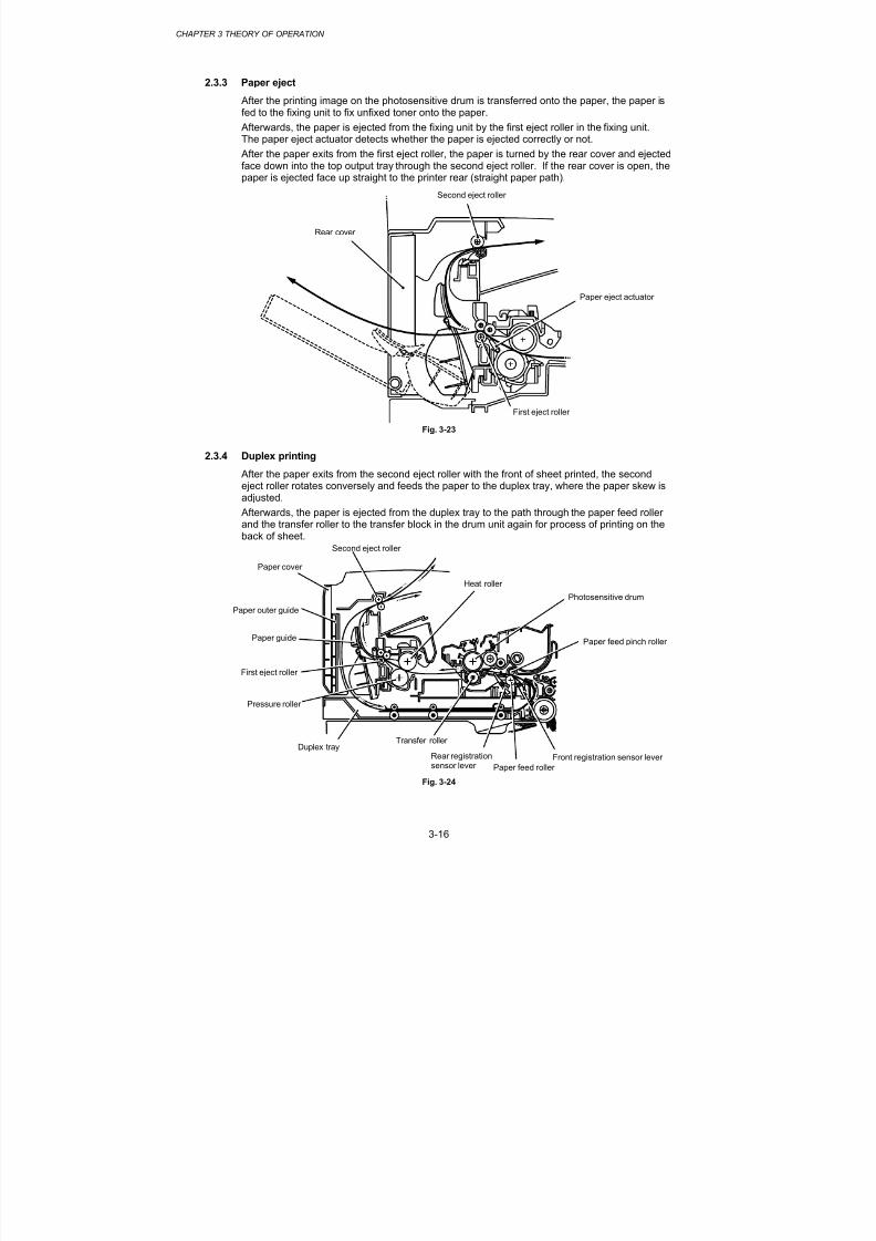
8/9/2019 DCP8040 DCP8045D MFC8440 MFC8840D MFC8840DN Manuales Técnicos.pdf
http://slidepdf.com/reader/full/dcp8040-dcp8045d-mfc8440-mfc8840d-mfc8840dn-manuales-tecnicospdf 72/361
CHAPTER 3 THEORY OF OPERATION
3-16
2.3.3 Paper eject
After the printing image on the photosensitive drum is transferred onto the paper, the paper isfed to the fixing unit to fix unfixed toner onto the paper.
Afterwards, the paper is ejected from the fixing unit by the first eject roller in the fixing unit.The paper eject actuator detects whether the paper is ejected correctly or not.
After the paper exits from the first eject roller, the paper is turned by the rear cover and ejectedface down into the top output tray through the second eject roller. If the rear cover is open, thepaper is ejected face up straight to the printer rear (straight paper path).
Fig. 3-23
2.3.4 Duplex printing After the paper exits from the second eject roller with the front of sheet printed, the secondeject roller rotates conversely and feeds the paper to the duplex tray, where the paper skew isadjusted.
Afterwards, the paper is ejected from the duplex tray to the path through the paper feed rollerand the transfer roller to the transfer block in the drum unit again for process of printing on theback of sheet.
Fig. 3-24
Second eject roller
Rear cover
Paper eject actuator
First eject roller
Second eject roller
Paper cover
Heat roller
Photosensitive drum
Paper feed pinch roller
Front registration sensor lever
Paper feed roller
Rear registration
sensor lever
Transfer rollerDuplex tray
Pressure roller
First eject roller
Paper guide
Paper outer guide

8/9/2019 DCP8040 DCP8045D MFC8440 MFC8840D MFC8840DN Manuales Técnicos.pdf
http://slidepdf.com/reader/full/dcp8040-dcp8045d-mfc8440-mfc8840d-mfc8840dn-manuales-tecnicospdf 73/361
MFC-8440/8840D/8840DN, DCP-8040/8045D/8045DNSERVICE MANUAL
3-17
2.4 Sensors
2.4.1 Cover sensors
Detect opening and closing of the front cover.
Fig. 3-25
2.4.2 Toner sensors
Detects if there is toner in the toner cartridge. The toner sensor at the left side emits lightthrough the window on the left side of the toner cartridge, then the toner sensor at the rightside receives it when the toner is low. They also detect whether or not the drum unit isinstalled. (The toner cartridge is installed in the drum unit.)
Fig. 3-26
Toner sensor (Light emission)
Toner sensor(Light reception)
Front cover sensor
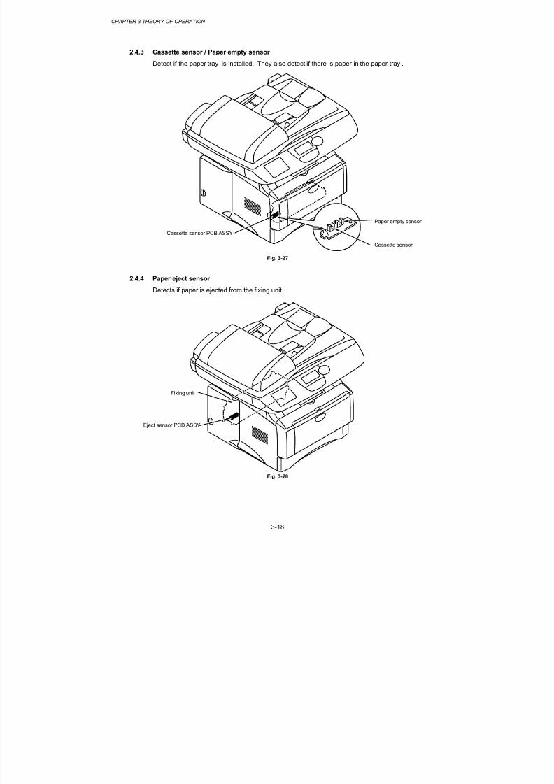
8/9/2019 DCP8040 DCP8045D MFC8440 MFC8840D MFC8840DN Manuales Técnicos.pdf
http://slidepdf.com/reader/full/dcp8040-dcp8045d-mfc8440-mfc8840d-mfc8840dn-manuales-tecnicospdf 74/361
CHAPTER 3 THEORY OF OPERATION
3-18
2.4.3 Cassette sensor / Paper empty sensor
Detect if the paper tray is installed. They also detect if there is paper in the paper tray .
Fig. 3-27
2.4.4 Paper eject sensor
Detects if paper is ejected from the fixing unit.
Fig. 3-28
Paper empty sensor
Eject sensor PCB ASSY
Cassette sensor PCB ASSY
Cassette sensor
Fixing unit

8/9/2019 DCP8040 DCP8045D MFC8440 MFC8840D MFC8840DN Manuales Técnicos.pdf
http://slidepdf.com/reader/full/dcp8040-dcp8045d-mfc8440-mfc8840d-mfc8840dn-manuales-tecnicospdf 75/361
MFC-8440/8840D/8840DN, DCP-8040/8045D/8045DNSERVICE MANUAL
3-19
2.4.5 MP-PE sensor
Detects if there is paper in the MP tray.
Fig. 3-29
2.4.6 Document cover sensor
Fig. 3-30
Feed MP unit
MP-PE sensor PCB ASSY
Document cover sensor

8/9/2019 DCP8040 DCP8045D MFC8440 MFC8840D MFC8840DN Manuales Técnicos.pdf
http://slidepdf.com/reader/full/dcp8040-dcp8045d-mfc8440-mfc8840d-mfc8840dn-manuales-tecnicospdf 76/361
CHAPTER 3 THEORY OF OPERATION
3-20
2.4.7 Document front sensor /Document rear sensor
Fig. 3-31
2.4.8 DX-sensor PCB ASSY
Fig. 3-32
Document front sensor
Document rear sensor
DX-sensor PCB ASSY

8/9/2019 DCP8040 DCP8045D MFC8440 MFC8840D MFC8840DN Manuales Técnicos.pdf
http://slidepdf.com/reader/full/dcp8040-dcp8045d-mfc8440-mfc8840d-mfc8840dn-manuales-tecnicospdf 77/361
MFC-8440/8840D/8840DN, DCP-8040/8045D/8045DNSERVICE MANUAL
3-21
2.4.9 Rear cover sensor
Fig. 3-33
2.4.10 HP sensor
Fig. 3-34
Rear cover sensor
HP sensor

8/9/2019 DCP8040 DCP8045D MFC8440 MFC8840D MFC8840DN Manuales Técnicos.pdf
http://slidepdf.com/reader/full/dcp8040-dcp8045d-mfc8440-mfc8840d-mfc8840dn-manuales-tecnicospdf 78/361
CHAPTER 3 THEORY OF OPERATION
3-22
2.5 Drum Unit
2.5.1 Photosensitive drum
Generates the latent electrostatic image and develops the image on the drum surface.
2.5.2 Primary chargerForms a uniform charge on the drum surface.
(1) Corona wireGenerates the ion charge on the drum.
(2) GridSpreads the ion charge evenly over the drum surface.
2.5.3 Transfer roller
Transfers the toner image to the paper from the drum surface.
2.5.4 CleanerRemoves the paper dust or dirt on the surface of the photosensitive drum.
2.6 Toner Cartridge
Develops the electrostatic latent image on the photosensitive drum with toner and forms thevisible image.
2.7 Print Process
2.7.1 Charging
The drum is charged to approximately 870V by an ion charge which is generated by theprimary charger. The charge is generated by ionization of the corona wire, which has a DCbias from the high-voltage power supply applied to it. The flow of the ion charge is controlledby the grid to ensure it is distributed evenly on the drum surface. The aluminum drum sleevein the photosensitive drum is grounded.
+++
++ + + + +
++
+++
+++
+ + ++
-- --- -- - - - -
Fig. 3-35
The primary charge uses a corona wire, but since the drum is positively charged, only less than1/10 of the usual quantity of ozone is generated compared with the negatively charged drum.The level of ozone expelled from the printer is therefore not harmful to the human body.
Applicable safety standards have been complied with.
Aluminum drum sleeveOrganic photoconductor layer
Photosensitivedrum
Voltageregulator
870V Grid
HVPS
Corona wire

8/9/2019 DCP8040 DCP8045D MFC8440 MFC8840D MFC8840DN Manuales Técnicos.pdf
http://slidepdf.com/reader/full/dcp8040-dcp8045d-mfc8440-mfc8840d-mfc8840dn-manuales-tecnicospdf 79/361
MFC-8440/8840D/8840DN, DCP-8040/8045D/8045DNSERVICE MANUAL
3-23
2.7.2 Exposure stage
After the drum is positively charged, it is exposed to the light emitted from the laser unit.
Fig. 3-36
The area exposed to the laser beam is the image to be printed. The surface potential of theexposed area is reduced, forming the electrostatic image to be printed.
Fig. 3-37
Drum
Lens
Laser beam
Polygon mirror
Paper
Laser detector
Laser diode
Motor
Laser beam
f θ lens
3 Primary charging
Laser beam exposure and developing
(a) Unexposed area
(Non image area)
(b) Exposed area
(Image area)
Transfer the image to paper
Time
Drumsleeve 0
21 1
2
3
(a)
(b)
+150
+400
+870
Surfacepotential (V)
1 Cycle of drum

8/9/2019 DCP8040 DCP8045D MFC8440 MFC8840D MFC8840DN Manuales Técnicos.pdf
http://slidepdf.com/reader/full/dcp8040-dcp8045d-mfc8440-mfc8840d-mfc8840dn-manuales-tecnicospdf 80/361
CHAPTER 3 THEORY OF OPERATION
3-24
2.7.3 Developing
Developing causes the toner to be attracted to the electrostatic image on the drum so as totransform it into a visible image.
The developer consists of a non-magnetic toner. The development roller is made ofconductive rubber and the supply roller (which is also made of conductive sponge) rotate
against each other. The toner is charged and carried from the supply roller to the developmentroller. The toner adheres to the development roller and is conveyed to the photosensitive drumat an even thickness controlled by the blade. The toner is nipped between the developmentroller and the drum and developed onto the latent image on the drum. The electrostatic fieldbetween the drum and the development roller, which is DC-biased from the high-voltage powersupply, creates the electrostatic potential to attract toner particles from the development rollerto the latent image area on the drum surface.
Fig. 3-38
2.7.4 Transfer
(1) Transfer process
After the drum has been charged and exposed, and has received a developed image, thetoner formed is transferred onto the paper by applying a negative charge to the back ofthe paper. The negative charge applied to the paper causes the positively charged tonerto leave the drum, and adhere to the paper. As a result, the image is visible on the paper.
(2) Cleaning process of transfer roller
If the toner is not transferred onto the paper perfectly it is possible that there may be
residual toner on the drum which will adhere to the transfer roller. The transfer voltagechanges to a positive voltage during non-printing rotation of the drum. Therefore thetransfer roller is cleaned by returning the positively charged toner adhering to the transferroller onto the photo-conductive drum.
Photosensitive drum
Corona wireDevelopment roller
Blade
Supply roller Transfer roller

8/9/2019 DCP8040 DCP8045D MFC8440 MFC8840D MFC8840DN Manuales Técnicos.pdf
http://slidepdf.com/reader/full/dcp8040-dcp8045d-mfc8440-mfc8840d-mfc8840dn-manuales-tecnicospdf 81/361
MFC-8440/8840D/8840DN, DCP-8040/8045D/8045DNSERVICE MANUAL
3-25
2.7.5 Fixing stage
The image transferred to the paper by static electricity is fixed by heat and pressure whenpassing through the heat roller and the pressure roller in the fixing unit. The thermistor keepsthe surface temperature of the heat roller constant by detecting the surface temperature of theheat roller and turning on or off the halogen heater lamp.
Fig. 3-39
First eject roller
Thermistor
Pressure roller
Heat roller
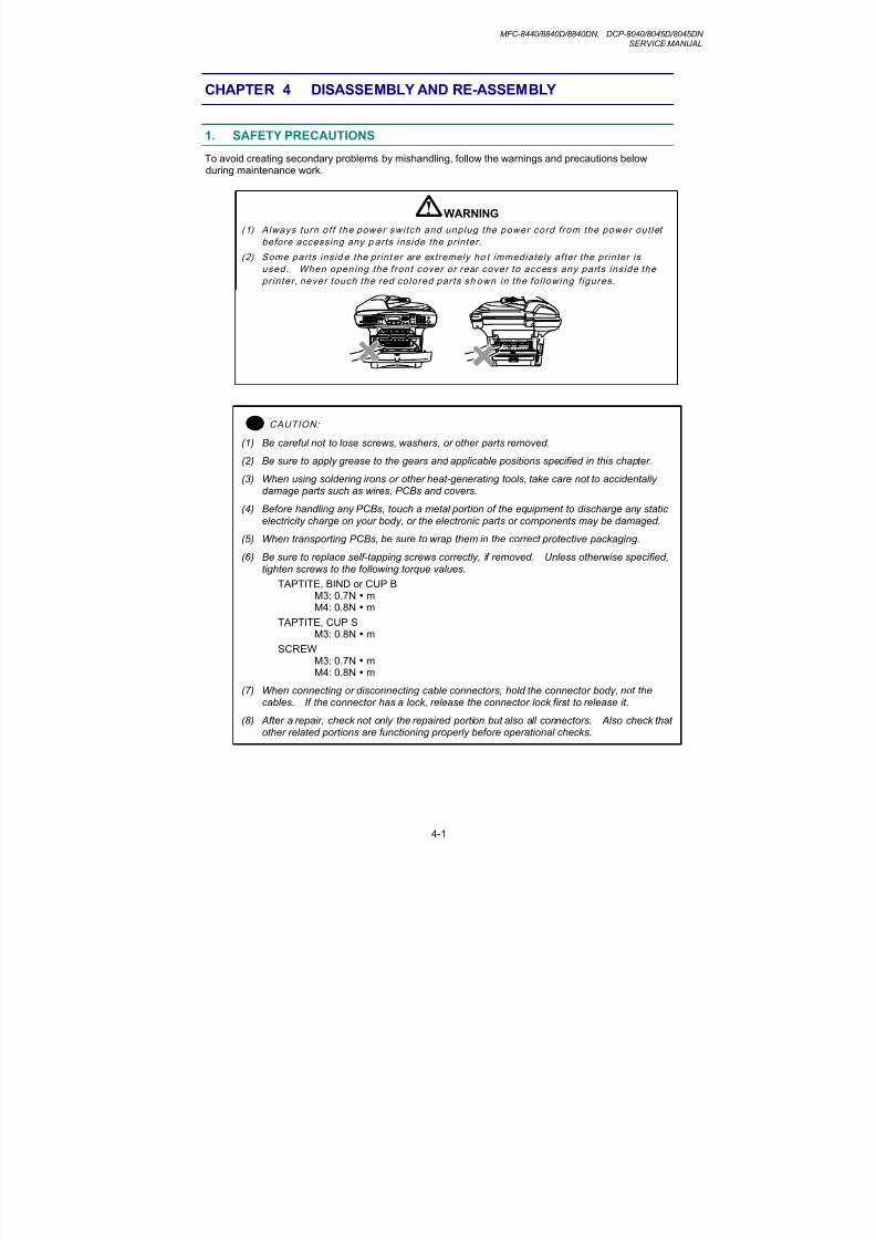
8/9/2019 DCP8040 DCP8045D MFC8440 MFC8840D MFC8840DN Manuales Técnicos.pdf
http://slidepdf.com/reader/full/dcp8040-dcp8045d-mfc8440-mfc8840d-mfc8840dn-manuales-tecnicospdf 82/361
MFC-8440/8840D/8840DN, DCP-8040/8045D/8045DNSERVICE MANUAL
4-1
CHAPTER 4 DISASSEMBLY AND RE-ASSEMBLY
1. SAFETY PRECAUTIONS
To avoid creating secondary problems by mishandling, follow the warnings and precautions belowduring maintenance work.
WARNING
(1) Always turn of f the power switch and unplug the power cord from the power out let
before accessing any p arts inside the printer.
(2) Some parts insid e the print er are extremely ho t immediately after the printer is
used. When opening the front cover or rear cover to access any parts inside the
pr in ter , never touch the red colored par ts sh own in the fo l lowing f igures.
! CAUTION:
(1) Be careful not to lose screws, washers, or other parts removed.
(2) Be sure to apply grease to the gears and applicable positions specified in this chapter.
(3) When using soldering irons or other heat-generating tools, take care not to accidentallydamage parts such as wires, PCBs and covers.
(4) Before handling any PCBs, touch a metal portion of the equipment to discharge any staticelectricity charge on your body, or the electronic parts or components may be damaged.
(5) When transporting PCBs, be sure to wrap them in the correct protective packaging.
(6) Be sure to replace self-tapping screws correctly, if removed. Unless otherwise specified,tighten screws to the following torque values.
TAPTITE, BIND or CUP BM3: 0.7N mM4: 0.8N m
TAPTITE, CUP SM3: 0.8N m
SCREWM3: 0.7N mM4: 0.8N m
(7) When connecting or disconnecting cable connectors, hold the connector body, not thecables. If the connector has a lock, release the connector lock first to release it.
(8) After a repair, check not only the repaired portion but also all connectors. Also check thatother related portions are functioning properly before operational checks.

8/9/2019 DCP8040 DCP8045D MFC8440 MFC8840D MFC8840DN Manuales Técnicos.pdf
http://slidepdf.com/reader/full/dcp8040-dcp8045d-mfc8440-mfc8840d-mfc8840dn-manuales-tecnicospdf 83/361
CHAPTER 4 DISASSEMBLY AND RE-ASSEMBLY
4-2
2. DISASSEMBLY FLOW
AC CORD
1
DRUM UNIT
2
PAPER TRAY
3
DX FEED ASSY(MFC-8840D/8840DN, DCP-8045D/8045DN only)
4
OUTER CHUTE(MFC-8440, DCP-8040 only)
11
REAR COVER C(MFC-8440, DCP-8040 only)
10
REAR COVER MP ASSY / OUTER CHUTE MP ASSY(MFC-8840D/8840DN, DCP-8045D/8045DN only)
12
13
REAR COVER SENSOR
18
6
(3.5 (1) and (2) are contained. )
DRIVER PCB ACCESS COVER
5
ACCESS COVER/BATTERY
7
ADF UNIT
9
PANEL UNIT
8
DOCUMENT SCANNER
REAR COVER L/R
SIDE COVER L/R
14
MAIN PCB
22
FRONT C(MFC-844
16
MP UNIT(MFC-884
REVERSING RELEASE SOLENOID(MFC-8840D/8840DN, DCP-8045D/8045DN only
DX-SENSOR PCB ASSY(MFC-8840D/8840DN, DCP-8045D/8045DN only)
17
BASE PLATE / LV INSULATION SHEET
23
LASER UNIT
21
FRAME L / DRIVE UNIT
PAPER FEEDER
28
29
30
THERMISTOR ASSY
31
JOINT COVER
15
HIGH-VOLTAGE PS PCB ASSY
LOW-VOLTAGE PS PCB ASSY
26
24
ENGINE PCB
25
27
NCU (MFC-8440/8840D/8840DN)
19
FIXING UNIT
20

8/9/2019 DCP8040 DCP8045D MFC8440 MFC8840D MFC8840DN Manuales Técnicos.pdf
http://slidepdf.com/reader/full/dcp8040-dcp8045d-mfc8440-mfc8840d-mfc8840dn-manuales-tecnicospdf 84/361
MFC-8440/8840D/8840DN, DCP-8040/8045D/8045DNSERVICE MANUAL
4-3
3. DISASSEMBLY PROCEDURE
3.1 AC Cord
(1) Disconnect the AC cord from the machine.
Fig. 4-1
3.2 Drum Unit
(1) Open the front cover and remove the drum unit.
Fig. 4-2
AC cord
Machine
Drum unit
Front cover

8/9/2019 DCP8040 DCP8045D MFC8440 MFC8840D MFC8840DN Manuales Técnicos.pdf
http://slidepdf.com/reader/full/dcp8040-dcp8045d-mfc8440-mfc8840d-mfc8840dn-manuales-tecnicospdf 85/361
CHAPTER 4 DISASSEMBLY AND RE-ASSEMBLY
4-4
3.3 Paper Tray
(1) Close the front cover and pull out the paper tray.
(2) Remove the paper from the paper tray.
Fig. 4-3
(3) Remove the pad holder and the separation pad spring from the paper tray.
Fig. 4-4
Front cover
Paper tray
Pad holder
Separation pad spring
Paper tray
1
2

8/9/2019 DCP8040 DCP8045D MFC8440 MFC8840D MFC8840DN Manuales Técnicos.pdf
http://slidepdf.com/reader/full/dcp8040-dcp8045d-mfc8440-mfc8840d-mfc8840dn-manuales-tecnicospdf 86/361
MFC-8440/8840D/8840DN, DCP-8040/8045D/8045DNSERVICE MANUAL
4-5
NOTE:
When replacing/re-assembling the pad holder ZL2 ASSY, remove the old grease and apply asuitable amount of grease referring to the figure below;
Fig. 4-5
(4) Remove the four bind B M4x12 Taptite screws, and then remove the paper tray frontcover.
Fig. 4-6
Paper tray
Paper pick-up roller
Grease: Molykote PG-662(4 mm dia.ball)
Taptite, bind B M4x12
Taptite, bind BM4x12
Paper tray front cover
Paper tray
Hook
Hook

8/9/2019 DCP8040 DCP8045D MFC8440 MFC8840D MFC8840DN Manuales Técnicos.pdf
http://slidepdf.com/reader/full/dcp8040-dcp8045d-mfc8440-mfc8840d-mfc8840dn-manuales-tecnicospdf 87/361
CHAPTER 4 DISASSEMBLY AND RE-ASSEMBLY
4-6
(5) Remove the two cup B M3x10 Taptite screws, and then remove the paper tray cover.
Fig. 4-7
(6) Remove the pressure roller holder.
Fig. 4-8
Paper tray
Taptite, cupB M3x10
Paper tray cover
Flat screwdriver
Pressure roller holder
Paper tray
Taptite, cup B M3x10

8/9/2019 DCP8040 DCP8045D MFC8440 MFC8840D MFC8840DN Manuales Técnicos.pdf
http://slidepdf.com/reader/full/dcp8040-dcp8045d-mfc8440-mfc8840d-mfc8840dn-manuales-tecnicospdf 88/361
MFC-8440/8840D/8840DN, DCP-8040/8045D/8045DNSERVICE MANUAL
4-7
(7) Remove the pressure roller collar.
(8) Remove the pressure roller shaft.
Fig. 4-9
(9) Remove the scratch spongy holder ASSY from the pressure roller holder.
(10) Remove the two scratch spongy springs.
(11) Remove the scratch spongy from the scratch spongy holder ASSY.
Fig. 4-10
Pressure roller shaft
Pressure roller holder ASSY
Scratch spongy
Scratch spongy holder ASSY
Pressure roller holderScratch spongy springs
1
2
Pressure roller collar
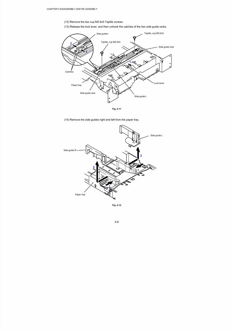
8/9/2019 DCP8040 DCP8045D MFC8440 MFC8840D MFC8840DN Manuales Técnicos.pdf
http://slidepdf.com/reader/full/dcp8040-dcp8045d-mfc8440-mfc8840d-mfc8840dn-manuales-tecnicospdf 89/361
CHAPTER 4 DISASSEMBLY AND RE-ASSEMBLY
4-8
(12) Remove the two cup M2.6x5 Taptite screws.
(13) Release the lock lever, and then unhook the catches of the two side guide racks.
Fig. 4-11
(14) Remove the side guides right and left from the paper tray.
Fig. 4-12
Taptite, cup M2.6x5
Taptite, cup M2.6x5
Side guide rack
Lock leverPaper tray
Catches
Paper tray
Side guide L
Side guide R
Side guide L
Side guide L
2
2
1
2
1
2
1
Side guide rack

8/9/2019 DCP8040 DCP8045D MFC8440 MFC8840D MFC8840DN Manuales Técnicos.pdf
http://slidepdf.com/reader/full/dcp8040-dcp8045d-mfc8440-mfc8840d-mfc8840dn-manuales-tecnicospdf 90/361
MFC-8440/8840D/8840DN, DCP-8040/8045D/8045DNSERVICE MANUAL
4-9
(15) Unhook the two catches (A) of the pressure plate while pulling the plastic frame outwards,then unhook the other two catches (B) of the plate while pulling the plastic frame outwardsto remove the pressure plate ASSY.
Fig. 4-13
(16) Unhook the pressure plate spring from the plastic hook to remove the two pressure plate
springs.
Fig. 4-14
Pressure plate ASSY
Plastic frame
Catches (A)
Paper tray
Paper tray
Pressure plate spring
Pressure plate spring
Catch (B)
Hook

8/9/2019 DCP8040 DCP8045D MFC8440 MFC8840D MFC8840DN Manuales Técnicos.pdf
http://slidepdf.com/reader/full/dcp8040-dcp8045d-mfc8440-mfc8840d-mfc8840dn-manuales-tecnicospdf 91/361
CHAPTER 4 DISASSEMBLY AND RE-ASSEMBLY
4-10
NOTE:
When re-assembling the pressure plate ASSY, ensure that the paper indicator arm is under the pressure plate.
! CAUTION:
When unhooking the catches to remove the pressure plate, do not bend the pressure plate,gently ease the plastic cover. If the pressure plate is deformed, paper feeding problems mayoccur.
(17) Remove the herical extension spring.
(18) Remove the lock lever.
Fig. 4-15
NOTE:
When re-assembling the lock lever, insert it upwards from underneath the cassette and rotateit until the two catches lock into place.
Herical extension spring
Lock lever
1
2
3
Paper tray
Paper tray
Lock lever

8/9/2019 DCP8040 DCP8045D MFC8440 MFC8840D MFC8840DN Manuales Técnicos.pdf
http://slidepdf.com/reader/full/dcp8040-dcp8045d-mfc8440-mfc8840d-mfc8840dn-manuales-tecnicospdf 92/361
MFC-8440/8840D/8840DN, DCP-8040/8045D/8045DNSERVICE MANUAL
4-11
(19) Remove the cup B M3x8 Taptite screw, and then remove the side guide gear and thefriction spring.
(20) Remove the two side guide racks.
Fig. 4-16
(21) Remove the paper indicator.
Fig. 4-17
Side guide rack
Side guide rack
Paper tray
Paper indicator
Taptite, cup B M3x8
Side guide gear
Friction spring
2
1
1
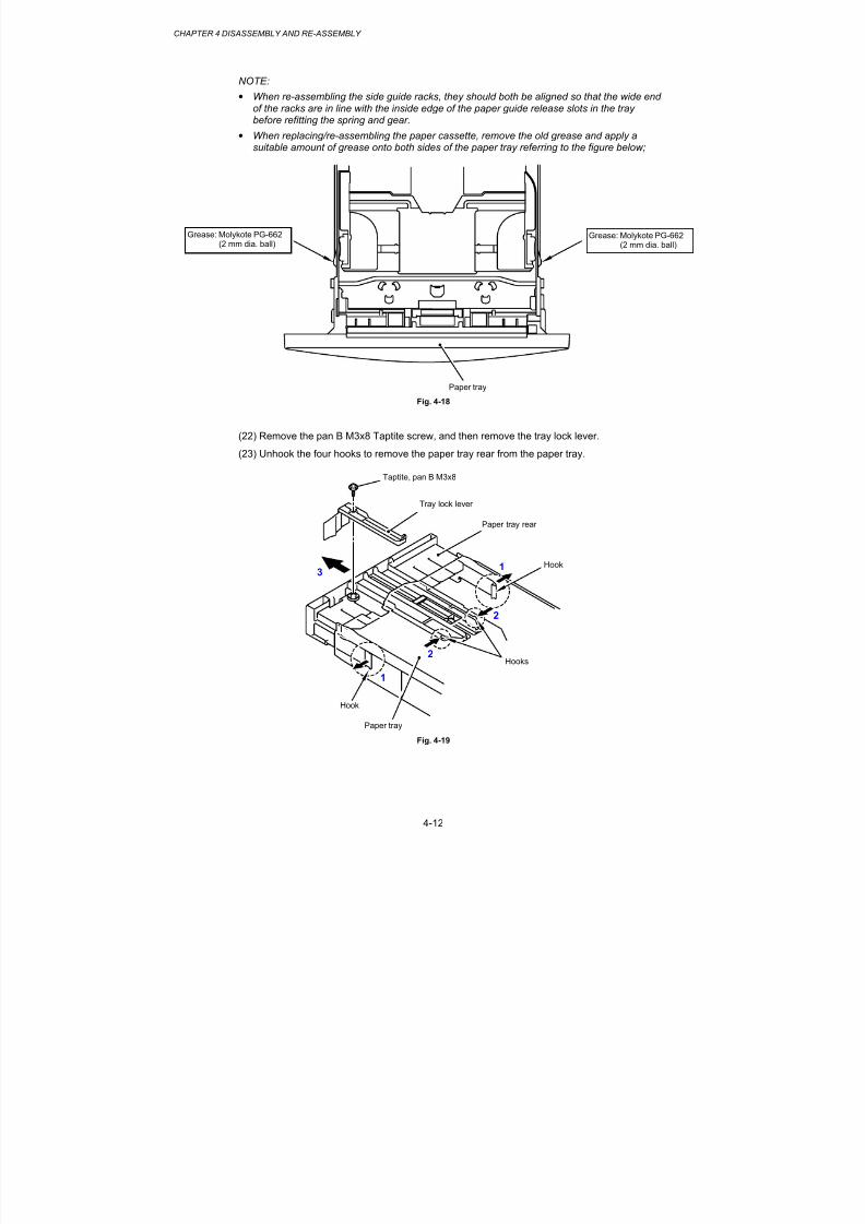
8/9/2019 DCP8040 DCP8045D MFC8440 MFC8840D MFC8840DN Manuales Técnicos.pdf
http://slidepdf.com/reader/full/dcp8040-dcp8045d-mfc8440-mfc8840d-mfc8840dn-manuales-tecnicospdf 93/361
CHAPTER 4 DISASSEMBLY AND RE-ASSEMBLY
4-12
NOTE:
• When re-assembling the side guide racks, they should both be aligned so that the wide endof the racks are in line with the inside edge of the paper guide release slots in the traybefore refitting the spring and gear.
• When replacing/re-assembling the paper cassette, remove the old grease and apply a
suitable amount of grease onto both sides of the paper tray referring to the figure below;
Fig. 4-18
(22) Remove the pan B M3x8 Taptite screw, and then remove the tray lock lever.
(23) Unhook the four hooks to remove the paper tray rear from the paper tray.
Fig. 4-19
Taptite, pan B M3x8
Tray lock lever
Paper tray
Hook
Paper tray rear
Paper tray
Grease: Molykote PG-662(2 mm dia. ball)
Grease: Molykote PG-662(2 mm dia. ball)
Hooks
Hook
1
1
2
2
3

8/9/2019 DCP8040 DCP8045D MFC8440 MFC8840D MFC8840DN Manuales Técnicos.pdf
http://slidepdf.com/reader/full/dcp8040-dcp8045d-mfc8440-mfc8840d-mfc8840dn-manuales-tecnicospdf 94/361
MFC-8440/8840D/8840DN, DCP-8040/8045D/8045DNSERVICE MANUAL
4-13
(24) Remove the paper rear guide.
Fig. 4-20
Paper tray
Paper rear guide
2
1
1

8/9/2019 DCP8040 DCP8045D MFC8440 MFC8840D MFC8840DN Manuales Técnicos.pdf
http://slidepdf.com/reader/full/dcp8040-dcp8045d-mfc8440-mfc8840d-mfc8840dn-manuales-tecnicospdf 95/361
CHAPTER 4 DISASSEMBLY AND RE-ASSEMBLY
4-14
3.4 DX Feed ASSY (MFC-8840D/8840DN, DCP-8045D/8045DN only)
(1) Remove the DX feed ASSY.
Fig. 4-21
(2) Remove the four bind B M3x8 Taptite screws, and then remove the DX roller holder and
three pressure rollers.(3) Remove the three pressure roller springs.
Fig. 4-22
DX feed ASSY
Tray feed ZL2
Pressure roller
Pressure roller spring
Taptite, bind B M3x8
Taptite, bind B M3x8
Pressure rollers
Pressure roller springs
DX roller holder

8/9/2019 DCP8040 DCP8045D MFC8440 MFC8840D MFC8840DN Manuales Técnicos.pdf
http://slidepdf.com/reader/full/dcp8040-dcp8045d-mfc8440-mfc8840d-mfc8840dn-manuales-tecnicospdf 96/361
MFC-8440/8840D/8840DN, DCP-8040/8045D/8045DNSERVICE MANUAL
4-15
NOTE:
Set pressure roller, and assemble pressure roller spring after assembling DX roller holder.
Fig. 4-23
(4) Remove the two bind B M3x8 Taptite screws, and then remove the guide plate stopper.
(5) Remove the two left guide spring 2.
Fig. 4-24
Left guide spring 2
Taptite, bind B M3x8
Taptite, bind B M3x8
Guide plate stopper
Guide plate stopper
Left guide spring 2
Left guide spring 2
Tray feed ZL2
Tray feed ZL2
Pressure roller
Pressure roller spring
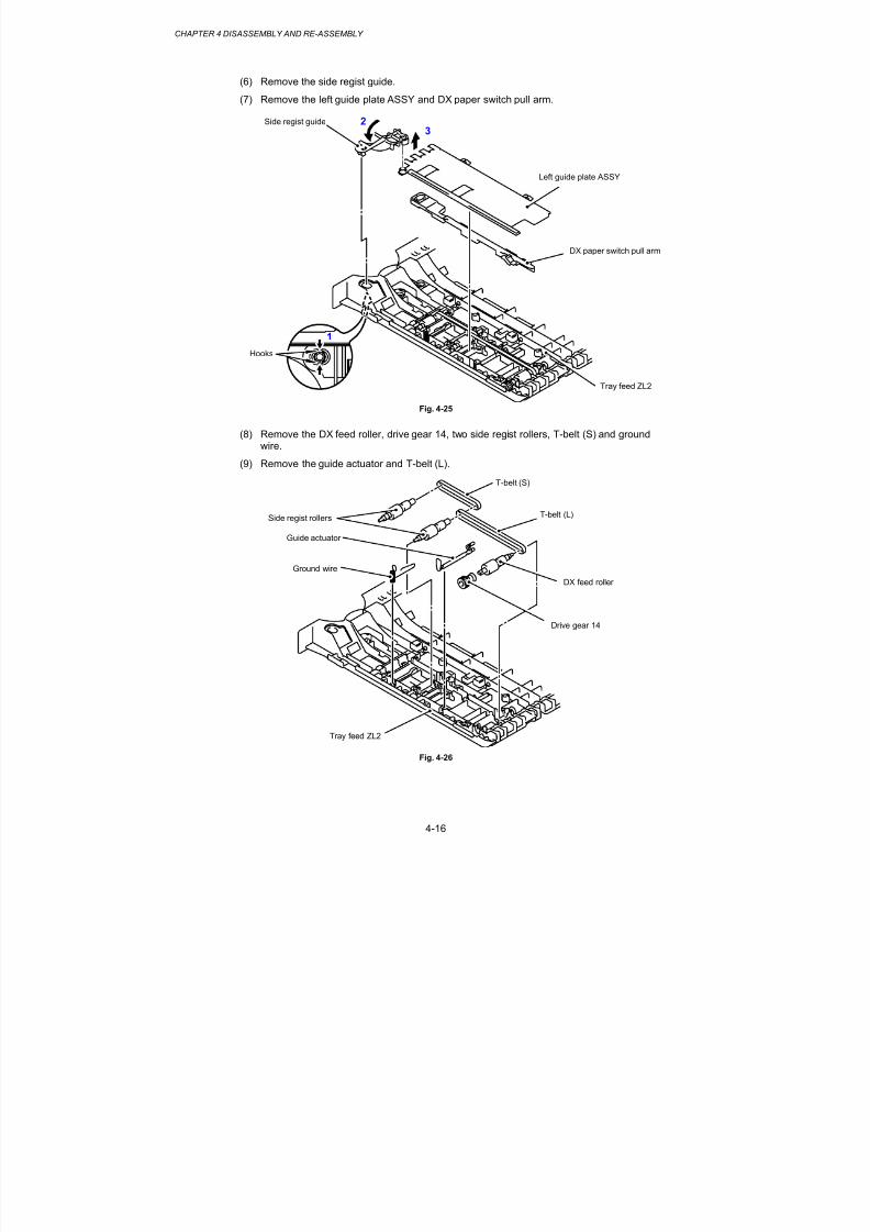
8/9/2019 DCP8040 DCP8045D MFC8440 MFC8840D MFC8840DN Manuales Técnicos.pdf
http://slidepdf.com/reader/full/dcp8040-dcp8045d-mfc8440-mfc8840d-mfc8840dn-manuales-tecnicospdf 97/361
CHAPTER 4 DISASSEMBLY AND RE-ASSEMBLY
4-16
(6) Remove the side regist guide.
(7) Remove the left guide plate ASSY and DX paper switch pull arm.
Fig. 4-25
(8) Remove the DX feed roller, drive gear 14, two side regist rollers, T-belt (S) and groundwire.
(9) Remove the guide actuator and T-belt (L).
Fig. 4-26
Tray feed ZL2
DX paper switch pull arm
Left guide plate ASSY
Side regist guide
DX feed roller
T-belt (S)
T-belt (L)
Drive gear 14
Tray feed ZL2
Hooks
1
23
Guide actuator
Ground wire
Side regist rollers

8/9/2019 DCP8040 DCP8045D MFC8440 MFC8840D MFC8840DN Manuales Técnicos.pdf
http://slidepdf.com/reader/full/dcp8040-dcp8045d-mfc8440-mfc8840d-mfc8840dn-manuales-tecnicospdf 98/361
MFC-8440/8840D/8840DN, DCP-8040/8045D/8045DNSERVICE MANUAL
4-17
3.5 Access Cover / Battery
(1) Remove the access cover.
(2) Loosen the two access plate screws.
(3) Remove the access plate.
Fig. 4-27
(4) Disconnect the connector, and then remove the battery. (MFC-8440/8840D/8840DN only)
Fig. 4-28
Access cover
Hooks
Hooks
Hooks
Hooks
Access plate
Access plate screw
Access platescrew
Battery
Main PCB

8/9/2019 DCP8040 DCP8045D MFC8440 MFC8840D MFC8840DN Manuales Técnicos.pdf
http://slidepdf.com/reader/full/dcp8040-dcp8045d-mfc8440-mfc8840d-mfc8840dn-manuales-tecnicospdf 99/361
CHAPTER 4 DISASSEMBLY AND RE-ASSEMBLY
4-18
3.6 Driver PCB Access Cover
(1) Remove the bind B M4x12 Taptite screw, and then remove the driver PCB access cover.
Fig. 4-29
Driver PCB access cover
Taptite, bind B M4x12

8/9/2019 DCP8040 DCP8045D MFC8440 MFC8840D MFC8840DN Manuales Técnicos.pdf
http://slidepdf.com/reader/full/dcp8040-dcp8045d-mfc8440-mfc8840d-mfc8840dn-manuales-tecnicospdf 100/361
MFC-8440/8840D/8840DN, DCP-8040/8045D/8045DNSERVICE MANUAL
4-19
3.7 ADF Unit
(1) Remove the document tray ASSY.
Fig. 4-30
(2) Disconnect the three connectors.
(3) Remove the cup B M3x10 Taptite screw, and then remove the ground wire.
Fig. 4-31
Taptite, cup B M3x10
Ground wire
Connector
Connector
Connector
Main PCB
Driver PCB ASSY
Document tray ASSY
Hooks
Hooks
12

8/9/2019 DCP8040 DCP8045D MFC8440 MFC8840D MFC8840DN Manuales Técnicos.pdf
http://slidepdf.com/reader/full/dcp8040-dcp8045d-mfc8440-mfc8840d-mfc8840dn-manuales-tecnicospdf 101/361
CHAPTER 4 DISASSEMBLY AND RE-ASSEMBLY
4-20
(4) Remove the two bind B M4x12 Taptite screws, and then remove the document cover.
Fig. 4-32
(5) Remove the hinge base R.
(6) Remove the three cup B M3x10 Taptite screws, and then remove the hinge arm R.(7) Remove the three cup B M3x10 Taptite screws, and then remove the hinge ASSY L.
Fig. 4-33
Document cover
Taptite, cup B M3x10
Taptite, cup B M3x10Taptite, cup B M3x10
Hinge base R
Hinge arm R
Hinge ASSY L
Document cover LGL
1
2
Hinge arm R
Hinge base R
Taptite, bind BM4x12

8/9/2019 DCP8040 DCP8045D MFC8440 MFC8840D MFC8840DN Manuales Técnicos.pdf
http://slidepdf.com/reader/full/dcp8040-dcp8045d-mfc8440-mfc8840d-mfc8840dn-manuales-tecnicospdf 102/361
MFC-8440/8840D/8840DN, DCP-8040/8045D/8045DNSERVICE MANUAL
4-21
(8) Remove the document hold ASSY and document hold spring.
(9) Remove the two cup B M3x10 Taptite screws, and then remove the rear sensor cover.
Fig. 4-34
(10) Remove the ADF cover.
Fig. 4-35
Document hold ASSY
Taptite, cup B M3x10
Rear sensor cover
ADF cover
Documenthold spring
Document hold ASSY
Hooks
Hooks
Hook
1
2
3
4
2
1
Document cover LGL
Document hold spring
Hooks

8/9/2019 DCP8040 DCP8045D MFC8440 MFC8840D MFC8840DN Manuales Técnicos.pdf
http://slidepdf.com/reader/full/dcp8040-dcp8045d-mfc8440-mfc8840d-mfc8840dn-manuales-tecnicospdf 103/361
CHAPTER 4 DISASSEMBLY AND RE-ASSEMBLY
4-22
(11) Remove the document ejection tray.
Fig. 4-36
(12) Remove the cup B M3x10 Taptite screw, and then remove the side cover F.
(13) Remove the cup B M3x10 Taptite screw, and then remove the side cover R.
Fig. 4-37
Document ejection tray
Document cover LGL
Side cover F
Side cover R
Taptite, cup BM3x10
Taptite, cup B M3x10
Hook
Hook
Document cover LGL
2
1
3
4
Hook
Hook

8/9/2019 DCP8040 DCP8045D MFC8440 MFC8840D MFC8840DN Manuales Técnicos.pdf
http://slidepdf.com/reader/full/dcp8040-dcp8045d-mfc8440-mfc8840d-mfc8840dn-manuales-tecnicospdf 104/361
MFC-8440/8840D/8840DN, DCP-8040/8045D/8045DNSERVICE MANUAL
4-23
(14) Disconnect the four connectors.
(15) Remove the cup S M3x6 Taptite screw, and then remove the ground wire.
(16) Remove the four cup B M3x10 Taptite screws, and then remove the ADF chute ASSY.
Fig. 4-38
(17) Remove the conductive bushing, and then remove the PF roller holder ASSY.
(18) Remove the conductive bushing, and then remove the LF roller 1 ASSY.
Fig. 4-39
Document cover LGL
Taptite, cup B M3x10
Taptite, cup B M3x10
ADF chute ASSY
Conductive bushings
LF roller 1 ASSY
PF roller holder ASSY
ADF chute ASSY
Conductive bushing
ADF motor
ADF relay PCB ASSY
Taptite, cup S M3x6Ground wire
Connector
Connector
2
1
1
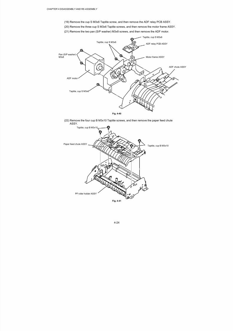
8/9/2019 DCP8040 DCP8045D MFC8440 MFC8840D MFC8840DN Manuales Técnicos.pdf
http://slidepdf.com/reader/full/dcp8040-dcp8045d-mfc8440-mfc8840d-mfc8840dn-manuales-tecnicospdf 105/361
CHAPTER 4 DISASSEMBLY AND RE-ASSEMBLY
4-24
(19) Remove the cup S M3x6 Taptite screw, and then remove the ADF relay PCB ASSY.
(20) Remove the three cup S M3x6 Taptite screws, and then remove the motor frame ASSY.
(21) Remove the two pan (S/P washer) M3x8 screws, and then remove the ADF motor.
Fig. 4-40
(22) Remove the four cup B M3x10 Taptite screws, and then remove the paper feed chute
ASSY.
Fig. 4-41
ADF chute ASSY
Taptite, cup S M3x6
ADF relay PCB ASSY
ADF motor
Pan (S/P washer)M3x8
Taptite, cup S M3x6
Motor frame ASSY
Taptite, cup B M3x10
Taptite, cup B M3x10
Paper feed chute ASSY
PF roller holder ASSY
Taptite, cup S M3x6

8/9/2019 DCP8040 DCP8045D MFC8440 MFC8840D MFC8840DN Manuales Técnicos.pdf
http://slidepdf.com/reader/full/dcp8040-dcp8045d-mfc8440-mfc8840d-mfc8840dn-manuales-tecnicospdf 106/361
MFC-8440/8840D/8840DN, DCP-8040/8045D/8045DNSERVICE MANUAL
4-25
(23) Remove the ADF film.
(24) Remove the B M3x6 Taptite screw, and then remove the spring plate ADF front A ASSY.
(25) Remove the separation rubber, rubber holder and compression spring.
(26) Remove the two pressure rollers and pressure roller shaft S.
Fig. 4-42
(27) Remove the front sensor actuator ASSY and document front sensor.
Fig. 4-43
Taptite, bind B M3x6
Pressure rollers
Spring plate ADF front A ASSY
Separation rubber
Rubber holder
Pressure roller shaft S
Front sensor actuator ASSY Connector
Paper feed chute
Document front sensor
Paper feed chute
Compression spring
ADF film
Hook
Pressure roller shaft S
21
Hook
12
3

8/9/2019 DCP8040 DCP8045D MFC8440 MFC8840D MFC8840DN Manuales Técnicos.pdf
http://slidepdf.com/reader/full/dcp8040-dcp8045d-mfc8440-mfc8840d-mfc8840dn-manuales-tecnicospdf 107/361
CHAPTER 4 DISASSEMBLY AND RE-ASSEMBLY
4-26
(28) Remove the conductive bushing, and then remove the LF roller 2 ASSY.
(29) Remove the conductive bushing, and then remove the ejection roller ASSY.
Fig. 4-44
(30) Remove the two pressure rollers and pressure roller shaft S.(31) Remove the two cup S M3x10 Taptite screws, and then remove the two LF springs.
(32) Remove the two pressure rollers and pressure roller shaft S.
Fig. 4-45
LF roller 2 ASSY
Conductive bushing
Ejection roller ASSY
Taptite, cupS M3x10
Pressure rollers
Pressure rollers
Pressure roller shaft S
Pressure roller shaft S
LF springs
Pressure rollers
Pressure rollers Pressure roller shaft S
Pressure roller shaft S
PF roller holder
Pressure roller shaft S
Hook
21
Conductive bushing
1
1
2

8/9/2019 DCP8040 DCP8045D MFC8440 MFC8840D MFC8840DN Manuales Técnicos.pdf
http://slidepdf.com/reader/full/dcp8040-dcp8045d-mfc8440-mfc8840d-mfc8840dn-manuales-tecnicospdf 108/361
MFC-8440/8840D/8840DN, DCP-8040/8045D/8045DNSERVICE MANUAL
4-27
(33) Remove the film.
(34) Remove the document rear sensor, and then disconnect the connector.
(35) Remove the document cover sensor.
Fig. 4-46
Document rear sensor
Document coversensor
Document cover LGL
Document rear sensor
1
2
Connector
Connector
Film

8/9/2019 DCP8040 DCP8045D MFC8440 MFC8840D MFC8840DN Manuales Técnicos.pdf
http://slidepdf.com/reader/full/dcp8040-dcp8045d-mfc8440-mfc8840d-mfc8840dn-manuales-tecnicospdf 109/361
CHAPTER 4 DISASSEMBLY AND RE-ASSEMBLY
4-28
3.8 Document Scanner
NOTE:
The disassembly job of the scanner unit should be done in a clean room to prevent dust or dirtfrom getting into the scanner unit.
(1) Disconnect the FFC cable.
(2) Remove the two cup B M3x10 Taptite screws, and then remove the driver PCB shield.
(3) Disconnect the two connectors.
Fig. 4-47
(4) Remove the two bind B M4x20 Taptite screws, and then remove the scanner unit.
Fig. 4-48
Taptite, bind B M4x20
Scanning motorFB harness
Document scanner
Document scanner
Taptite, cup BM3x10
Photo interrupter harness
FFC cable
Driver PCB ASSY
Driver PCB shield
Main PCB
1 2
Driver PCB shield

8/9/2019 DCP8040 DCP8045D MFC8440 MFC8840D MFC8840DN Manuales Técnicos.pdf
http://slidepdf.com/reader/full/dcp8040-dcp8045d-mfc8440-mfc8840d-mfc8840dn-manuales-tecnicospdf 110/361
MFC-8440/8840D/8840DN, DCP-8040/8045D/8045DNSERVICE MANUAL
4-29
(5) Remove the six cup B M4x12 Taptite screws, and then remove the top cover ASSY.
Fig. 4-49
(6) Remove the cup B M3x6 Taptite screw, and then remove the lock lever B.
(7) Remove the two cup B M3x6 Taptite screws, and then remove the lock lever ASSY.
NOTE: After moving the lock lever ASSY to “A” direction, assemble “B” of lock lever B that is to thedirection of the top cover rib in touch.
Fig. 4-50
Taptite, cup B M4x12
Taptite, cup B M4x12
Taptite, cup B M4x12
Taptite, cup B M4x12
Top cover ASSY
Taptite, cup B M3x6
Taptite, cup B M3x6
Lock lever B
Lock lever ASSY
Lock lever B
Scanner base ASSY
“B”
Lock lever ASSY
Top cover
“A”

8/9/2019 DCP8040 DCP8045D MFC8440 MFC8840D MFC8840DN Manuales Técnicos.pdf
http://slidepdf.com/reader/full/dcp8040-dcp8045d-mfc8440-mfc8840d-mfc8840dn-manuales-tecnicospdf 111/361
CHAPTER 4 DISASSEMBLY AND RE-ASSEMBLY
4-30
(8) Remove the guide shaft from the CCD module.
(9) Release the belt from the pulley ASSY.
(10) Remove the belt support rubber, and then remove the belt from the CCD module.
(11) Disconnect the FFC cable from the CCD module.
(12) Remove the CCD module from the scanner base.
Fig. 4-51
CCD module
Guide shaft
Belt
2
1
Pulley ASSYScanner base
Belt
CCD module
Belt
4
5
7
6Belt support rubber
3

8/9/2019 DCP8040 DCP8045D MFC8440 MFC8840D MFC8840DN Manuales Técnicos.pdf
http://slidepdf.com/reader/full/dcp8040-dcp8045d-mfc8440-mfc8840d-mfc8840dn-manuales-tecnicospdf 112/361
MFC-8440/8840D/8840DN, DCP-8040/8045D/8045DNSERVICE MANUAL
4-31
(13) Remove the cup B M3x8 Taptite screw, and then remove the FFC plate.
(14) Remove the sponge and FFC cable ASSY.
Fig. 4-52
(15) Remove the cup S M3x6 Taptite screw, and then remove the ground wire.
(16) Remove the four pan B M3x8 Taptite screws, and then remove the drive plate ASSY.
(17) Remove the HP sensor, and then disconnect the connector.
Fig. 4-53
FFC plate
FFC cable ASSY
Taptite, cup S M3x6
Scanner base
Sponge
Hook
Taptite, cup B M3x8
Pin
Ground wire
Taptite, pan B M3x8
Taptite, pan BM3x8
Drive plate ASSY
Connector
HP sensor
Scanner base

8/9/2019 DCP8040 DCP8045D MFC8440 MFC8840D MFC8840DN Manuales Técnicos.pdf
http://slidepdf.com/reader/full/dcp8040-dcp8045d-mfc8440-mfc8840d-mfc8840dn-manuales-tecnicospdf 113/361
CHAPTER 4 DISASSEMBLY AND RE-ASSEMBLY
4-32
(18) Remove the two pan (S/P washer) M3x6 screws, and then remove the scanning motorFB.
Fig. 4-54
(19) Remove the B M3x6 Taptite screw, and then remove the pulley ASSY and pulley spring.
Fig. 4-55
Pulley spring
Taptite, B M3x6
Pulley ASSY
Scanner base
Drive plate ASSY
Scanning motor FB
Pan (S/P washer) M3x6

8/9/2019 DCP8040 DCP8045D MFC8440 MFC8840D MFC8840DN Manuales Técnicos.pdf
http://slidepdf.com/reader/full/dcp8040-dcp8045d-mfc8440-mfc8840d-mfc8840dn-manuales-tecnicospdf 114/361
MFC-8440/8840D/8840DN, DCP-8040/8045D/8045DNSERVICE MANUAL
4-33
3.9 Panel Unit
(1) Remove the four cup B M4x12 Taptite screws, and then remove the connector and panelunit.
Fig. 4-56
(2) Remove the six cup B M3x8 Taptite screws, and then remove the panel rear cover.
Fig. 4-57
Panel unit
Taptite, cup B M3x8
Taptite, cup B M3x8
Panel rear cover
Panel cover
Taptite, cup B M4x12
Taptite, cup B M4x12
Panel PCB harness
1
2
Hook
Hooks

8/9/2019 DCP8040 DCP8045D MFC8440 MFC8840D MFC8840DN Manuales Técnicos.pdf
http://slidepdf.com/reader/full/dcp8040-dcp8045d-mfc8440-mfc8840d-mfc8840dn-manuales-tecnicospdf 115/361
CHAPTER 4 DISASSEMBLY AND RE-ASSEMBLY
4-34
(3) Disconnect the three cables.
Fig. 4-58
(4) Remove the two cup B M3x8 Taptite screws, and then remove panel PCB ASSY.
Fig. 4-59
Panel cover
Lock
Cables
1
2
Lock
Cable
Taptite, cup B M3x8
Panel cover
Hooks
Panel PCB ASSY
1
2

8/9/2019 DCP8040 DCP8045D MFC8440 MFC8840D MFC8840DN Manuales Técnicos.pdf
http://slidepdf.com/reader/full/dcp8040-dcp8045d-mfc8440-mfc8840d-mfc8840dn-manuales-tecnicospdf 116/361
MFC-8440/8840D/8840DN, DCP-8040/8045D/8045DNSERVICE MANUAL
4-35
(5) Remove the backlight holder and the deffusion film.
Fig. 4-60
(6) Remove the LCD.
Fig. 4-61
Backlight holder
Deffusion film
Panel cover
2
1
3
4
LCD
Hooks
Hooks
Hook
LCD
Panel cover
LCD
Hook

8/9/2019 DCP8040 DCP8045D MFC8440 MFC8840D MFC8840DN Manuales Técnicos.pdf
http://slidepdf.com/reader/full/dcp8040-dcp8045d-mfc8440-mfc8840d-mfc8840dn-manuales-tecnicospdf 117/361
CHAPTER 4 DISASSEMBLY AND RE-ASSEMBLY
4-36
3.10 Rear Cover C (MFC-8440, DCP-8040 only)
(1) Remove the bind B M4x12 Taptite screw, and then remove the rear cover C.
Fig. 4-62
Taptite, bind B M4x12
Rear cover C

8/9/2019 DCP8040 DCP8045D MFC8440 MFC8840D MFC8840DN Manuales Técnicos.pdf
http://slidepdf.com/reader/full/dcp8040-dcp8045d-mfc8440-mfc8840d-mfc8840dn-manuales-tecnicospdf 118/361
MFC-8440/8840D/8840DN, DCP-8040/8045D/8045DNSERVICE MANUAL
4-37
3.11 Outer Chute (MFC-8440, DCP-8040 only)
(1) Remove the outer chute.
Fig. 4-63
(2) Remove the outer chute tray.
Fig. 4-64
Hook
Outer Chute
Outer Chute
Outer chute tray

8/9/2019 DCP8040 DCP8045D MFC8440 MFC8840D MFC8840DN Manuales Técnicos.pdf
http://slidepdf.com/reader/full/dcp8040-dcp8045d-mfc8440-mfc8840d-mfc8840dn-manuales-tecnicospdf 119/361
CHAPTER 4 DISASSEMBLY AND RE-ASSEMBLY
4-38
3.12 Rear Cover MP ASSY / Outer Chute MP ASSY
(MFC-8840D/8840DN, DCP-8045D/8045DN only)
(1) Remove the rear cover MP ASSY.
Fig. 4-65
(2) Remove the outer chute MP ASSY.
Fig. 4-66
Outer chute MP ASSY
Rear cover MP ASSY
Hook
Hook
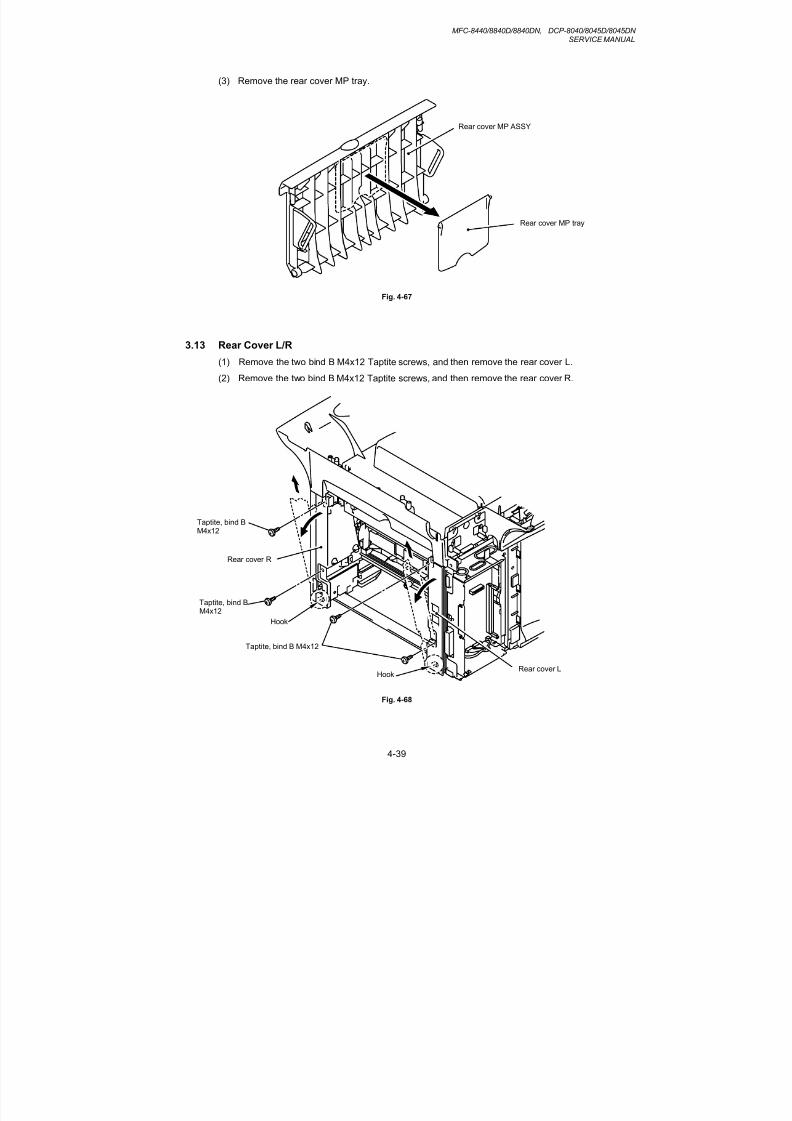
8/9/2019 DCP8040 DCP8045D MFC8440 MFC8840D MFC8840DN Manuales Técnicos.pdf
http://slidepdf.com/reader/full/dcp8040-dcp8045d-mfc8440-mfc8840d-mfc8840dn-manuales-tecnicospdf 120/361
MFC-8440/8840D/8840DN, DCP-8040/8045D/8045DNSERVICE MANUAL
4-39
(3) Remove the rear cover MP tray.
Fig. 4-67
3.13 Rear Cover L/R
(1) Remove the two bind B M4x12 Taptite screws, and then remove the rear cover L.
(2) Remove the two bind B M4x12 Taptite screws, and then remove the rear cover R.
Fig. 4-68
Rear cover MP ASSY
Rear cover MP tray
Taptite, bind B M4x12
Rear cover L
Taptite, bind BM4x12
Hook
Hook
Taptite, bind BM4x12
Rear cover R

8/9/2019 DCP8040 DCP8045D MFC8440 MFC8840D MFC8840DN Manuales Técnicos.pdf
http://slidepdf.com/reader/full/dcp8040-dcp8045d-mfc8440-mfc8840d-mfc8840dn-manuales-tecnicospdf 121/361
CHAPTER 4 DISASSEMBLY AND RE-ASSEMBLY
4-40
3.14 Side Cover L/R
(1) Remove the three bind B M4x12 Taptite screws, and then remove the side cover R.
Fig. 4-69
(2) Remove the four bind B M4x12 Taptite screws, and then remove the side cover L.
Fig. 4-70
Side cover R
Taptite, bind BM4x12
Side cover L
Taptite, bind B M4x12
Taptite, bind B M4x12
Taptite, bind B M4x12
Taptite, bind B M4x12
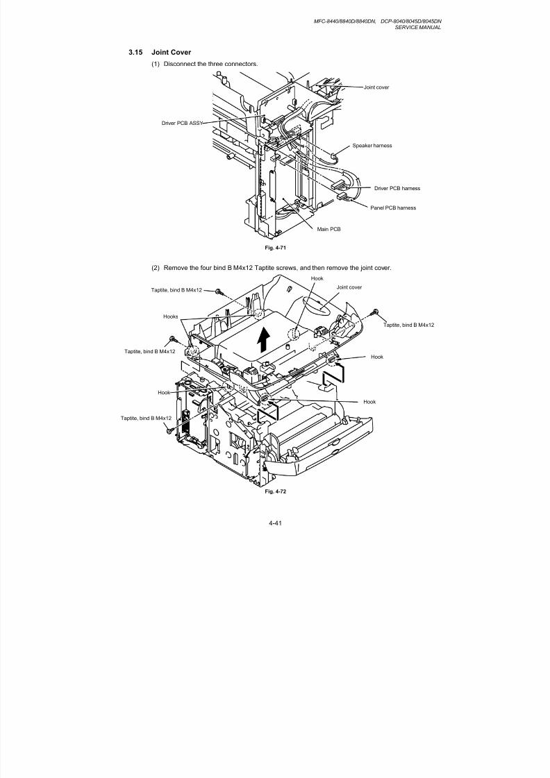
8/9/2019 DCP8040 DCP8045D MFC8440 MFC8840D MFC8840DN Manuales Técnicos.pdf
http://slidepdf.com/reader/full/dcp8040-dcp8045d-mfc8440-mfc8840d-mfc8840dn-manuales-tecnicospdf 122/361
MFC-8440/8840D/8840DN, DCP-8040/8045D/8045DNSERVICE MANUAL
4-41
3.15 Joint Cover
(1) Disconnect the three connectors.
Fig. 4-71
(2) Remove the four bind B M4x12 Taptite screws, and then remove the joint cover.
Fig. 4-72
Taptite, bind B M4x12
Taptite, bind B M4x12
Joint cover
Hook
Hooks
Hook
Hook
Hook
Panel PCB harness
Driver PCB harness
Speaker harness
Joint cover
Driver PCB ASSY
Main PCB
Taptite, bind B M4x12
Taptite, bind B M4x12

8/9/2019 DCP8040 DCP8045D MFC8440 MFC8840D MFC8840DN Manuales Técnicos.pdf
http://slidepdf.com/reader/full/dcp8040-dcp8045d-mfc8440-mfc8840d-mfc8840dn-manuales-tecnicospdf 123/361
CHAPTER 4 DISASSEMBLY AND RE-ASSEMBLY
4-42
(3) Remove the speaker hold spring and the speaker.
Fig. 4-73
(4) Remove the four bind B M4x12 Taptite screws, and then remove the inner chute.
Fig. 4-74
Speaker hold spring
Hook
Speaker
1
2
Taptite, bind B M4x12
Taptite, bind B M4x12
Taptite, bind B M4x12
Inner chute
Hooks
Hook
Joint cover

8/9/2019 DCP8040 DCP8045D MFC8440 MFC8840D MFC8840DN Manuales Técnicos.pdf
http://slidepdf.com/reader/full/dcp8040-dcp8045d-mfc8440-mfc8840d-mfc8840dn-manuales-tecnicospdf 124/361
MFC-8440/8840D/8840DN, DCP-8040/8045D/8045DNSERVICE MANUAL
4-43
(5) Remove the corrugation pinch roller L, R and pinch roller holder.
Fig. 4-75
(6) Remove the two bind B M4x12 Taptite screws, and then remove the joint cover front L.
(7) Remove the two bind B M4x12 Taptite screws, and then remove the joint cover front R.
Fig. 4-76
Taptite, bind B M4x12
Joint cover
Taptite, bind BM4x12
Joint cover front R
Joint cover front LHooks
Corrugation pinch roller L, R
Pinch roller holder
Inner chute

8/9/2019 DCP8040 DCP8045D MFC8440 MFC8840D MFC8840DN Manuales Técnicos.pdf
http://slidepdf.com/reader/full/dcp8040-dcp8045d-mfc8440-mfc8840d-mfc8840dn-manuales-tecnicospdf 125/361
CHAPTER 4 DISASSEMBLY AND RE-ASSEMBLY
4-44
(8) Remove the cup B M3x10 Taptite screw, and then remove the driver PCB ASSY.
Fig. 4-77
(9) Remove the support flap and the support flap S.
Fig. 4-78
Support flap
Support flap S
Taptite, cup B M3x10
Driver PCB harness
Joint cover
Driver PCB ASSY

8/9/2019 DCP8040 DCP8045D MFC8440 MFC8840D MFC8840DN Manuales Técnicos.pdf
http://slidepdf.com/reader/full/dcp8040-dcp8045d-mfc8440-mfc8840d-mfc8840dn-manuales-tecnicospdf 126/361
MFC-8440/8840D/8840DN, DCP-8040/8045D/8045DNSERVICE MANUAL
4-45
3.16 Front Cover ASSY (MFC-8440, DCP-8040 only)
(1) Release the link.
(2) Remove the front cover ASSY.
Fig. 4-79
Frame
Front cover ASSYLink

8/9/2019 DCP8040 DCP8045D MFC8440 MFC8840D MFC8840DN Manuales Técnicos.pdf
http://slidepdf.com/reader/full/dcp8040-dcp8045d-mfc8440-mfc8840d-mfc8840dn-manuales-tecnicospdf 127/361
CHAPTER 4 DISASSEMBLY AND RE-ASSEMBLY
4-46
3.17 MP Unit (MFC-8840D/8840DN, DCP-8045D/8045DN only)
(1) Disconnect the two connectors.
(2) Remove the MP ground spring.
(3) Remove the bind B M3x8 Taptite screw and cup S M3x6 Taptite screw.
(4) Remove the MP solenoid holder unit.
Fig. 4-80
(5) Remove the cup S M3x6 Taptite screw, and then open the MP chute ASSY cover.
(6) Remove the paper pick-up roller ASSY from the shaft.
Fig. 4-81
MP ground spring
Paper pick-up roller ASSY
Taptite, cup S M3x6
MP chute ASSY cover
MP sensor harness
Hook
Shaft
Engine PCBconnector
Taptite, bind BM3x8
MP solenoid holder unit
Taptite, cup S M3x6

8/9/2019 DCP8040 DCP8045D MFC8440 MFC8840D MFC8840DN Manuales Técnicos.pdf
http://slidepdf.com/reader/full/dcp8040-dcp8045d-mfc8440-mfc8840d-mfc8840dn-manuales-tecnicospdf 128/361
MFC-8440/8840D/8840DN, DCP-8040/8045D/8045DNSERVICE MANUAL
4-47
(7) While pushing the MP pressure plate, remove the separation plate ASSY.
Fig. 4-82
NOTE:
When replacing with the new separation plate ASSY, attach it after peeling the cover paper ofdouble-faced tape.
Fig. 4-83
Separation plate ASSY
MP chute ASSY
MP pressure plate
Separation plate ASSY
Double faced tape

8/9/2019 DCP8040 DCP8045D MFC8440 MFC8840D MFC8840DN Manuales Técnicos.pdf
http://slidepdf.com/reader/full/dcp8040-dcp8045d-mfc8440-mfc8840d-mfc8840dn-manuales-tecnicospdf 129/361
CHAPTER 4 DISASSEMBLY AND RE-ASSEMBLY
4-48
(8) Remove the shaft of the MP front cover ASSY from the drive release link, and thenremove the MP front cover ASSY from the MP chute ASSY.
Fig. 4-84
(9) Remove the bosses from the guide at 2 spots in the MP tray ASSY, and then remove the
MP paper guide ASSY.
Fig. 4-85
MP tray ASSY
MP front cover ASSY
Drive release link
MP chute ASSY
MP chute ASSY
MP paper guide ASSY
Shaft
Shaft

8/9/2019 DCP8040 DCP8045D MFC8440 MFC8840D MFC8840DN Manuales Técnicos.pdf
http://slidepdf.com/reader/full/dcp8040-dcp8045d-mfc8440-mfc8840d-mfc8840dn-manuales-tecnicospdf 130/361
MFC-8440/8840D/8840DN, DCP-8040/8045D/8045DNSERVICE MANUAL
4-49
(10) Remove the MP tray ASSY.
Fig. 4-86
(11) Remove the MP tray support flap 2 and the MP tray support flap 3 from the MP tray ASSY.
Fig. 4-87
MP tray support flap 3
MP tray support flap 2
MP tray ASSY
MP tray ASSY
MP chute ASSY

8/9/2019 DCP8040 DCP8045D MFC8440 MFC8840D MFC8840DN Manuales Técnicos.pdf
http://slidepdf.com/reader/full/dcp8040-dcp8045d-mfc8440-mfc8840d-mfc8840dn-manuales-tecnicospdf 131/361
CHAPTER 4 DISASSEMBLY AND RE-ASSEMBLY
4-50
(12) Open the MP chute ASSY cover.
(13) Remove the MP-PE actuator.
Fig. 4-88
(14) Remove the four bind B M4x12 Taptite screws, and then remove the MP chute ASSY.
Fig. 4-89
MP-PE actuator
Taptite, bind B M4x12
Taptite, bind B M4x12
MP chute ASSY
MP chute ASSY

8/9/2019 DCP8040 DCP8045D MFC8440 MFC8840D MFC8840DN Manuales Técnicos.pdf
http://slidepdf.com/reader/full/dcp8040-dcp8045d-mfc8440-mfc8840d-mfc8840dn-manuales-tecnicospdf 132/361
MFC-8440/8840D/8840DN, DCP-8040/8045D/8045DNSERVICE MANUAL
4-51
(15) Remove the cup S M3x6 Tite screws, and then remove the MP gear cover.
(16) Remove the MP roller cover.
(17) Remove the MP-PE sensor PCB ASSY.
Fig. 4-90
3.18 Rear Cover Sensor
(1) Disconnect the connector, and then remove the rear cover sensor.
Fig. 4-91
MP-PE sensor PCB ASSY
Hook (pin)
Hook
Hooks
Rear cover sensor
Connector
Hook
MP chute ASSY
Tite, cup S M3x6
MP gear cover
Hook (pin)
MP roller cover
Hook

8/9/2019 DCP8040 DCP8045D MFC8440 MFC8840D MFC8840DN Manuales Técnicos.pdf
http://slidepdf.com/reader/full/dcp8040-dcp8045d-mfc8440-mfc8840d-mfc8840dn-manuales-tecnicospdf 133/361
CHAPTER 4 DISASSEMBLY AND RE-ASSEMBLY
4-52
3.19 NCU (MFC-8440/8840D/8840DN only)
(1) Disconnect the connector.
(2) Remove the two cup S M3x6 Taptite screws, and then remove the NCU unit.
Fig. 4-92
(3) Remove the cup S M3x6 Taptite screw, and then remove the NCU shield cover.
(4) Remove the two cup S M3x6 Taptite screws, and then disconnect the connector.
(5) Remove the NCU.
Fig. 4-93
Taptite, cup S M3x6
Taptite, cup S M3x6
Taptite, cup S M3x6
Taptite, cup S M3x6
NCU harness
NCU shield cover
NCU shield plate
Hook
Hook
NCU harness
NCU
NCU unit

8/9/2019 DCP8040 DCP8045D MFC8440 MFC8840D MFC8840DN Manuales Técnicos.pdf
http://slidepdf.com/reader/full/dcp8040-dcp8045d-mfc8440-mfc8840d-mfc8840dn-manuales-tecnicospdf 134/361
MFC-8440/8840D/8840DN, DCP-8040/8045D/8045DNSERVICE MANUAL
4-53
3.20 Fixing Unit
(1) Disconnect the heater harness and thermistor harness.
(2) Remove the bind B M4x12 Taptite screw and the shoulder screw, and then remove thefixing unit.
Fig. 4-94
(3) Remove the three cup B M3x10 Taptite screws, and then remove the FU paper guide.
Fig. 4-95
Pin
Pins
FU paper guide
Taptite, cup B M3x10
Fixing unit
Fixing unit
Thermistor harness
Heater harness
Taptite, bind B M4x12
Shoulder screw

8/9/2019 DCP8040 DCP8045D MFC8440 MFC8840D MFC8840DN Manuales Técnicos.pdf
http://slidepdf.com/reader/full/dcp8040-dcp8045d-mfc8440-mfc8840d-mfc8840dn-manuales-tecnicospdf 135/361
CHAPTER 4 DISASSEMBLY AND RE-ASSEMBLY
4-54
(4) Remove the three cup B M3x10 Taptite screws, and then remove the star wheel holder.
Fig. 4-96
(5) Remove the cup B M3x12 Taptite screw.
(6) Release the thermistor ASSY harness from the hooks.
(7) Remove the thermistor ASSY.
Fig. 4-97
Thermistor relayPCB ASSY
Taptite, cup B M3x10
Fixing unit
Pins
Pin
Star wheel holder
Taptite, cup B M3x12
Fixing unitThermistor ASSY
Hooks
Hook
Thermistor relayPCB ASSY
Thermistor ASSY harness
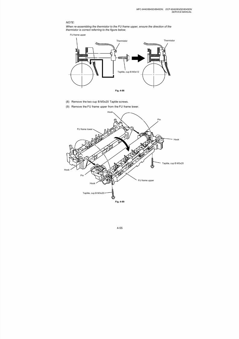
8/9/2019 DCP8040 DCP8045D MFC8440 MFC8840D MFC8840DN Manuales Técnicos.pdf
http://slidepdf.com/reader/full/dcp8040-dcp8045d-mfc8440-mfc8840d-mfc8840dn-manuales-tecnicospdf 136/361
MFC-8440/8840D/8840DN, DCP-8040/8045D/8045DNSERVICE MANUAL
4-55
NOTE:
When re-assembling the thermistor to the FU frame upper, ensure the direction of thethermistor is correct referring to the figure below;
Fig. 4-98
(8) Remove the two cup B M3x20 Taptite screws.
(9) Remove the FU frame upper from the FU frame lower.
Fig. 4-99
ThermistorThermistor
Taptite, cup B M3x12
FU frame upper
FU frame lower
Hook
Hook
Pin
FU frame upper
Hook
Pin
Hook
Taptite, cup B M3x20
Taptite, cup B M3x20

8/9/2019 DCP8040 DCP8045D MFC8440 MFC8840D MFC8840DN Manuales Técnicos.pdf
http://slidepdf.com/reader/full/dcp8040-dcp8045d-mfc8440-mfc8840d-mfc8840dn-manuales-tecnicospdf 137/361
CHAPTER 4 DISASSEMBLY AND RE-ASSEMBLY
4-56
(10) Remove the two pan (washer) M2.6x6 Taptite screws.
(11) Remove the heat roller 25.
(12) Remove the halogen lamp.
Fig. 4-100
NOTE:
When re-assembling the halogen heater lamp, ensure that the direction of the halogen heaterlamp is correct referring to the figure above.
! CAUTION:
• Never touch the surface of the halogen heater lamp.
• When securing the screw to assemble the halogen lamp connector plate, ensure you usethe Fu lamp assembly jig ASSY as shown in the figure below to avoid damaging the edge ofthe halogen heater lamp.
Fig. 4-101
Screw, pan (washer) M2.6x6
Fu lamp assembly jig ASSY
Halogen lamp connector plate
Halogen heater lamp
Screw, pan(washer) M2.6x6
Heat roller 25
FU frame upper
Heat roller 25
Halogen lamp
Halogen lampconnector plate
Screw, pan (washer)M2.6x6
Halogen lamp
Colored side115V:Orange230V:Black

8/9/2019 DCP8040 DCP8045D MFC8440 MFC8840D MFC8840DN Manuales Técnicos.pdf
http://slidepdf.com/reader/full/dcp8040-dcp8045d-mfc8440-mfc8840d-mfc8840dn-manuales-tecnicospdf 138/361
MFC-8440/8840D/8840DN, DCP-8040/8045D/8045DNSERVICE MANUAL
4-57
(13) Remove the HR bearing 25.
(14) Remove the HR gear 34.
(15) Remove the HR retaining ring 25.
(16) Remove the heat roller washer 25.
(17) Remove the HR bearing 25.
Fig. 4-102
!CAUTION:
Never touch the surface of the heat roller.
NOTE:
• When re-assembling the heat roller 25 to the FU frame upper, place the two projectionsonto the bosses on the frame as shown in the figure below.
Fig. 4-103
HR gear 34
HR retaining ring 25
Heat roller 25
HR bearing 25
Heat roller 25
(projection)
HR gear 34
HR bearing 25
(boss)
Heat roller washer 25
HR bearing 25

8/9/2019 DCP8040 DCP8045D MFC8440 MFC8840D MFC8840DN Manuales Técnicos.pdf
http://slidepdf.com/reader/full/dcp8040-dcp8045d-mfc8440-mfc8840d-mfc8840dn-manuales-tecnicospdf 139/361
CHAPTER 4 DISASSEMBLY AND RE-ASSEMBLY
4-58
• When re-assembling the heat roller 25 to the FU frame upper, ensure you do not damagethe heat roller 25 with the four separate claw ASSY on the FU frame upper.
Fig. 4-104
(18) Remove the pressure roller 25.
Fig. 4-105
Separate claw ASSY
FU frame upper
Separate claw ASSY
Heat roller 25
Pressure roller 25
FU frame lower
FU jam remove cover
2
3
1

8/9/2019 DCP8040 DCP8045D MFC8440 MFC8840D MFC8840DN Manuales Técnicos.pdf
http://slidepdf.com/reader/full/dcp8040-dcp8045d-mfc8440-mfc8840d-mfc8840dn-manuales-tecnicospdf 140/361
MFC-8440/8840D/8840DN, DCP-8040/8045D/8045DNSERVICE MANUAL
4-59
(19) Remove the three cleaner spring S.
(20) Remove the three cleaner pinch roller ASSY S.
(21) Remove the cleaner spring L.
(22) Remove the cleaner pinch roller ASSY L.
Fig. 4-106
NOTE:
• When re-assembling the cleaner pinch roller ASSY complete with the cleaner spring ontothe FU frame lower, ensure the direction of the roller is correct referring to the figure above.
• Ensure that the both springs are seated correctly in the locating channel and does not protrude from either end.
• Ensure also that the proper spring is fixed to the each cleaner pinch roller ASSY becausethe both springs are NOT identical with each other.
Fig. 4-107
FU frame lower
Cleaner pinch roller ASSY S
Cleaner pinch roller ASSY S
Cleaner pinch roller ASSY L
Cleaner spring S
Cleaner spring
FU frame lower
Cleaner pinch roller ASSY
Cleaner spring S
Cleaner spring L

8/9/2019 DCP8040 DCP8045D MFC8440 MFC8840D MFC8840DN Manuales Técnicos.pdf
http://slidepdf.com/reader/full/dcp8040-dcp8045d-mfc8440-mfc8840d-mfc8840dn-manuales-tecnicospdf 141/361
CHAPTER 4 DISASSEMBLY AND RE-ASSEMBLY
4-60
(23) Disconnect the connector for the eject sensor harness from the thermistor relay PCB ASSY.
(24) Release the eject sensor harness from the three hooks.
(25) Remove the bind B M3x10 Taptite screw, and then remove the eject sensor PCB ASSY.
(26) Remove the bind B M3x10 Taptite screw, and then remove the thermistor relay PCB ASSY.
Fig. 4-108
(27) Remove the paper eject actuator and eject actuator spring.
Fig. 4-109
Taptite, bind B M3x10
Taptite, bind B M3x10
FU frame lower
Thermistor relay PCB ASSY
Eject sensor PCB ASSY
FU frame lower
Eject actuator springPaper eject actuator
Hook
HooksHook
Eject sensor harness
1
2
3

8/9/2019 DCP8040 DCP8045D MFC8440 MFC8840D MFC8840DN Manuales Técnicos.pdf
http://slidepdf.com/reader/full/dcp8040-dcp8045d-mfc8440-mfc8840d-mfc8840dn-manuales-tecnicospdf 142/361
MFC-8440/8840D/8840DN, DCP-8040/8045D/8045DNSERVICE MANUAL
4-61
NOTE:
When re-assembling the paper eject actuator and the eject actuator spring to the FU framelower, ensure the paper eject actuator is seated correctly in the locating channel referring tothe figure below;
Fig. 4-110
(28) Disconnect the heater harness.
(29) Remove the four cup B M3x6 Taptite screws.
(30) Remove the four claw holder plate.
(31) Remove the four separate claw ASSY.
Fig. 4-111
Paper eject actuator
Eject actuator spring
FU frame lower
Separate claw ASSY
Separate claw ASSY
Heater harness
Claw holder plate
Taptite, cup B M3x6
Tweezers

8/9/2019 DCP8040 DCP8045D MFC8440 MFC8840D MFC8840DN Manuales Técnicos.pdf
http://slidepdf.com/reader/full/dcp8040-dcp8045d-mfc8440-mfc8840d-mfc8840dn-manuales-tecnicospdf 143/361
CHAPTER 4 DISASSEMBLY AND RE-ASSEMBLY
4-62
3.21 Laser Unit
(1) Remove the filter, and then remove the cup S M3x8 Taptite screw and the air duct.
Fig. 4-112
(2) Disconnect the LD harness 5P from the laser unit.
(3) Disconnect the polygon motor harness and remove the spongy from the laser unit.
(4) Remove the six cup S M3x8 Taptite screws, and then remove the laser unit.
Fig. 4-113
Filter
Air duct
Taptite, cup S M3x8
Taptite, cup SM3x8
LD harness 5P
Laser unit Polygon motor harness
Spongy
Taptite, cup S M3x8
Hook
Hook

8/9/2019 DCP8040 DCP8045D MFC8440 MFC8840D MFC8840DN Manuales Técnicos.pdf
http://slidepdf.com/reader/full/dcp8040-dcp8045d-mfc8440-mfc8840d-mfc8840dn-manuales-tecnicospdf 144/361
MFC-8440/8840D/8840DN, DCP-8040/8045D/8045DNSERVICE MANUAL
4-63
(5) Remove the shutter arm C.
Fig. 4-114
Shutter arm C
Frame L

8/9/2019 DCP8040 DCP8045D MFC8440 MFC8840D MFC8840DN Manuales Técnicos.pdf
http://slidepdf.com/reader/full/dcp8040-dcp8045d-mfc8440-mfc8840d-mfc8840dn-manuales-tecnicospdf 145/361
CHAPTER 4 DISASSEMBLY AND RE-ASSEMBLY
4-64
3.22 Main PCB
(1) Disconnect the LD harness 5P.
(2) Disconnect the four connectors.
Fig. 4-115
Main PCB ASSY
LVPS connector
Engine connector
LVPS connector
Thermistor connector
LD harness 5P

8/9/2019 DCP8040 DCP8045D MFC8440 MFC8840D MFC8840DN Manuales Técnicos.pdf
http://slidepdf.com/reader/full/dcp8040-dcp8045d-mfc8440-mfc8840d-mfc8840dn-manuales-tecnicospdf 146/361
MFC-8440/8840D/8840DN, DCP-8040/8045D/8045DNSERVICE MANUAL
4-65
(3) Remove the three pan M3x6 screws.
(4) Remove the five cup S M3x6 Taptite screws, and then remove the main PCB ASSY.
Fig. 4-116
NOTE:
After replacing the Main PCB, please perform the following operations.
• APPENDIX 1 EEPROM CUSTOMIZING CODES (Refer to A-1.)
• APPENDIX 2.1 INSTALING THE UPDATE DATA TO THE MACHINE (Refer to A-3.)
• APPENDIX 2.2 SETTING ID CODES TO MACHINES (Refer to A-5.)
• Chapter 7 3.12 CCD Scanner Area Setting (Maintenance mode 55) (Refer to P7-20.)
Main PCB ASSY
Taptite, cup S M3x6
Taptite, cup S M3x6
Screw, panM3x6

8/9/2019 DCP8040 DCP8045D MFC8440 MFC8840D MFC8840DN Manuales Técnicos.pdf
http://slidepdf.com/reader/full/dcp8040-dcp8045d-mfc8440-mfc8840d-mfc8840dn-manuales-tecnicospdf 147/361
CHAPTER 4 DISASSEMBLY AND RE-ASSEMBLY
4-66
3.23 Base Plate / LV Insulation Sheet
(1) Remove the eight bind B M4x12 Taptite screws.
(2) Remove the four cup S M3x6 Taptite screws.
(3) Remove the pan (washer) M3.5x6 Taptite screw, and then remove the ground wire.
(4) Remove the base plate.
Fig. 4-117
(5) Remove the two bind B M4x12 Taptite screws, and then remove the LV insulation sheet 1,2, 3.
Fig. 4-118
Taptite, cup S M3x6
Taptite, bind B M4x12Taptite, bind B M4x12
Taptite, bind B M4x12
Taptite, cup S M3x6
Base plate
Screw, pan(washer) M3.5x6
Ground wire
LV insulation sheet 2
Taptite, bind B M4x12
LV insulation sheet 1
LV insulation sheet 3

8/9/2019 DCP8040 DCP8045D MFC8440 MFC8840D MFC8840DN Manuales Técnicos.pdf
http://slidepdf.com/reader/full/dcp8040-dcp8045d-mfc8440-mfc8840d-mfc8840dn-manuales-tecnicospdf 148/361
MFC-8440/8840D/8840DN, DCP-8040/8045D/8045DNSERVICE MANUAL
4-67
3.24 DX-Sensor PCB ASSY (MFC-8840D/8840DN, DCP-8045D/8045DN only)
(1) Disconnect the connector.
(2) Remove the bind B M3x10 Taptite screws, and then remove the DX-sensor PCB ASSY.
Fig. 4-119
Taptite, bind B M3x10
DX-sensor PCB ASSY
Engine PCB ASSY

8/9/2019 DCP8040 DCP8045D MFC8440 MFC8840D MFC8840DN Manuales Técnicos.pdf
http://slidepdf.com/reader/full/dcp8040-dcp8045d-mfc8440-mfc8840d-mfc8840dn-manuales-tecnicospdf 149/361
CHAPTER 4 DISASSEMBLY AND RE-ASSEMBLY
4-68
3.25 Engine PCB
(1) Disconnect the connectors.
Fig. 4-120
(2) Remove the two bind B M4x12 Taptite screws, and then remove the engine PCB ASSY.
Fig. 4-121
Taptite, bind B M4x12
Engine PCB ASSY
Engine PCB ASSY
Toner sensor(light reception) connector
Thermistor relay PCB connector
Main motor connector
Main PCB connector
MP tray PCB connector
FR solenoid connector
PF solenoid connector
Fan motor 60 unit connector
LT connector
Polygon motor connector
Fan motor 60 connector
LVPS connector
Cassette sensor PCB connector
Toner sensor(light emission) connector
HVPS connector
Document cover sensor connector
DX sensor connector
Reversing release solenoid connector

8/9/2019 DCP8040 DCP8045D MFC8440 MFC8840D MFC8840DN Manuales Técnicos.pdf
http://slidepdf.com/reader/full/dcp8040-dcp8045d-mfc8440-mfc8840d-mfc8840dn-manuales-tecnicospdf 150/361
MFC-8440/8840D/8840DN, DCP-8040/8045D/8045DNSERVICE MANUAL
4-69
3.26 High-voltage PS PCB ASSY
(1) Remove the bind B M4x12 Taptite screw, and then remove the high-voltage PS PCB ASSY.
(2) Disconnect the flat cable from the high-voltage PS PCB ASSY.
Fig. 4-122
Taptite, bind B M4x12
Flat cable
High-voltage PS PCB ASSY

8/9/2019 DCP8040 DCP8045D MFC8440 MFC8840D MFC8840DN Manuales Técnicos.pdf
http://slidepdf.com/reader/full/dcp8040-dcp8045d-mfc8440-mfc8840d-mfc8840dn-manuales-tecnicospdf 151/361
CHAPTER 4 DISASSEMBLY AND RE-ASSEMBLY
4-70
3.27 Low-voltage PS PCB ASSY
(1) Remove the bind B M4x12 Taptite screw.
(2) Disconnect the three connectors from the low-voltage PS PCB, and then remove the low-voltage PS PCB.
Fig. 4-123
(3) Remove the two bind B M4x12 Taptite screws, and then remove the inlet holder.
(4) Remove the bind B M4x12 Taptite screw, and then remove the SW holder.
(5) Remove the Fan motor 60.
(6) Remove the low-voltage PS PCB.
Fig. 4-124
Main PCB/Engine
PCB Connector
Heater Connector
Taptite, bind B M4x12
Low-voltage PS PCB
Taptite, bind BM4x12
Inlet holder
Inlet
SW holder
Taptite, bind B M4x12
Low-voltage PS PCB
Main PCB connector
Fan motor 60

8/9/2019 DCP8040 DCP8045D MFC8440 MFC8840D MFC8840DN Manuales Técnicos.pdf
http://slidepdf.com/reader/full/dcp8040-dcp8045d-mfc8440-mfc8840d-mfc8840dn-manuales-tecnicospdf 152/361
MFC-8440/8840D/8840DN, DCP-8040/8045D/8045DNSERVICE MANUAL
4-71
3.28 Paper Feeder
(1) Remove the bearing R.
(2) Remove the paper pick-up roller ASSY.
(3) Remove the two roller collars from the paper pick-up roller ASSY.
Fig. 4-125
(4) Remove the bind B M3x10 Taptite screw, and then remove the PE sensor cover.
(5) Remove the cassette sensor PCB ASSY.
Fig. 4-126
Roller collar
Roller collar
Paper pick-up roller ASSY
Bearing R
Taptite, bind B M3x10
PE sensor cover
Cassette sensor PCB ASSY
1
2

8/9/2019 DCP8040 DCP8045D MFC8440 MFC8840D MFC8840DN Manuales Técnicos.pdf
http://slidepdf.com/reader/full/dcp8040-dcp8045d-mfc8440-mfc8840d-mfc8840dn-manuales-tecnicospdf 153/361
CHAPTER 4 DISASSEMBLY AND RE-ASSEMBLY
4-72
(6) Remove the PE actuator and the CA actuator.
Fig. 4-127
(7) Remove the spring, extension P/R from the gear 63P/R.
(8) Remove the gear 63P/R.
(9) Remove the ground spring from the conductor bearing.
Fig. 4-128
Gear 63P/R
Spring, extension P/R
Ground spring
PE actuator
CA actuator
Frame
Hooks
Conductor Bearing
Hooks

8/9/2019 DCP8040 DCP8045D MFC8440 MFC8840D MFC8840DN Manuales Técnicos.pdf
http://slidepdf.com/reader/full/dcp8040-dcp8045d-mfc8440-mfc8840d-mfc8840dn-manuales-tecnicospdf 154/361
MFC-8440/8840D/8840DN, DCP-8040/8045D/8045DNSERVICE MANUAL
4-73
(10) Remove the bearing L from the P/R shaft.
(11) Remove the P/R shaft.
Fig. 4-129
(12) Remove the idle gear 22.
(13) Remove the middle roller gear.
(14) Remove the bind B M3x10 taptite screw and the conductor bearing.
(15) Remove the 1st F/R shaft.
Fig. 4-130
Bearing L
P/R shaft
1st F/R shaft
Conductor bearing
Taptite bind B M3x10
Idle gear 22
Frame
Hook
1
2
Middle roller gear
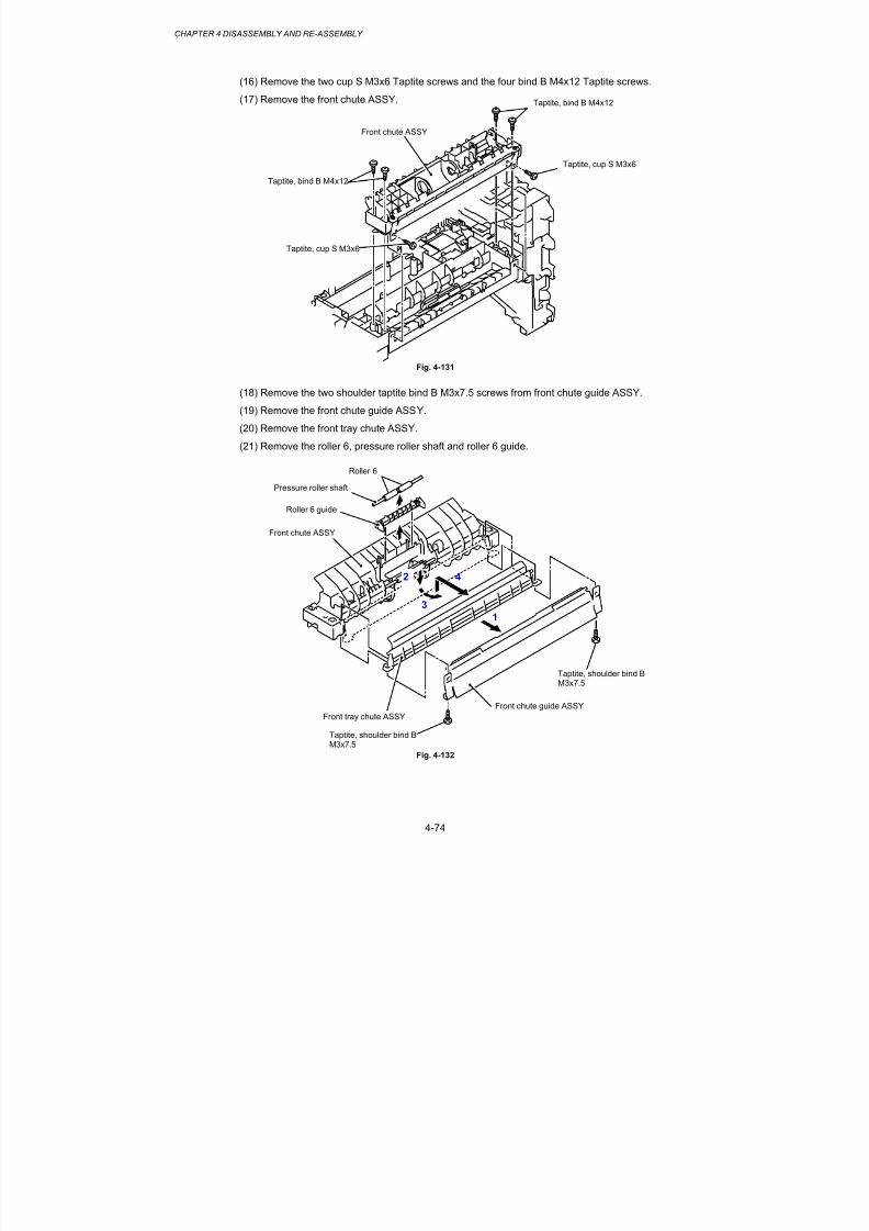
8/9/2019 DCP8040 DCP8045D MFC8440 MFC8840D MFC8840DN Manuales Técnicos.pdf
http://slidepdf.com/reader/full/dcp8040-dcp8045d-mfc8440-mfc8840d-mfc8840dn-manuales-tecnicospdf 155/361
CHAPTER 4 DISASSEMBLY AND RE-ASSEMBLY
4-74
(16) Remove the two cup S M3x6 Taptite screws and the four bind B M4x12 Taptite screws.
(17) Remove the front chute ASSY.
Fig. 4-131
(18) Remove the two shoulder taptite bind B M3x7.5 screws from front chute guide ASSY.
(19) Remove the front chute guide ASSY.
(20) Remove the front tray chute ASSY.
(21) Remove the roller 6, pressure roller shaft and roller 6 guide.
Fig. 4-132
Front chute ASSY
Taptite, bind B M4x12
Taptite, bind B M4x12
Taptite, cup S M3x6
Taptite, cup S M3x6
Roller 6 guide
Front tray chute ASSY
Front chute guide ASSY
Taptite, shoulder bind BM3x7.5
Taptite, shoulder bind BM3x7.5
Front chute ASSY
1
4
3
2
Pressure roller shaft
Roller 6

8/9/2019 DCP8040 DCP8045D MFC8440 MFC8840D MFC8840DN Manuales Técnicos.pdf
http://slidepdf.com/reader/full/dcp8040-dcp8045d-mfc8440-mfc8840d-mfc8840dn-manuales-tecnicospdf 156/361
MFC-8440/8840D/8840DN, DCP-8040/8045D/8045DNSERVICE MANUAL
4-75
(22) Remove the two bind B M4x12 Taptite screws, and then remove the chute 3.
Fig. 4-133
(23) Remove the feed roller gear.
(24) Remove the bearing F/R.
(25) Remove the feed roller gear shaft.
Fig. 4-134
Feed roller gear shaft
Feed roller gear
Bearing F/R
Bearing F/R
Hook
Frame
Taptite, bind B M4x12
Chute 3

8/9/2019 DCP8040 DCP8045D MFC8440 MFC8840D MFC8840DN Manuales Técnicos.pdf
http://slidepdf.com/reader/full/dcp8040-dcp8045d-mfc8440-mfc8840d-mfc8840dn-manuales-tecnicospdf 157/361
CHAPTER 4 DISASSEMBLY AND RE-ASSEMBLY
4-76
(26) Remove the hook of the bearing 5, and then slide the feed roller ASSY in the direction ofthe arrow.
(27) Remove the feed roller ASSY.
(28) Remove the joint 5 and the bearing 5 from the feed roller ASSY.
Fig. 4-135
NOTE:
Be careful that the different direction installation causes jam when you install joint 5.
Fig. 4-136
Bearing 5
Joint 5
Feed roller ASSY
Hook
1
2
3
4
5
Bearing 5
Joint 5

8/9/2019 DCP8040 DCP8045D MFC8440 MFC8840D MFC8840DN Manuales Técnicos.pdf
http://slidepdf.com/reader/full/dcp8040-dcp8045d-mfc8440-mfc8840d-mfc8840dn-manuales-tecnicospdf 158/361
MFC-8440/8840D/8840DN, DCP-8040/8045D/8045DNSERVICE MANUAL
4-77
(29) Remove the chute cover.
Fig. 4-137
(30) Remove the regist front actuator and regist front actuator spring.
(31) Remove the regist rear actuator and regist rear actuator spring.
Fig. 4-138
NOTE:
When assembling the regist front actuator and the regist rear actuator, set the spring as shownin the figure.
Fig. 4-139
Regist front actuator
Regist front actuator spring
Regist rear actuator
Regist rear actuator spring
Chute cover
Hook
Hook
Regist front actuator spring
Regist rear actuatorRegist rear actuator spring
Regist front actuator
Hole
Hole
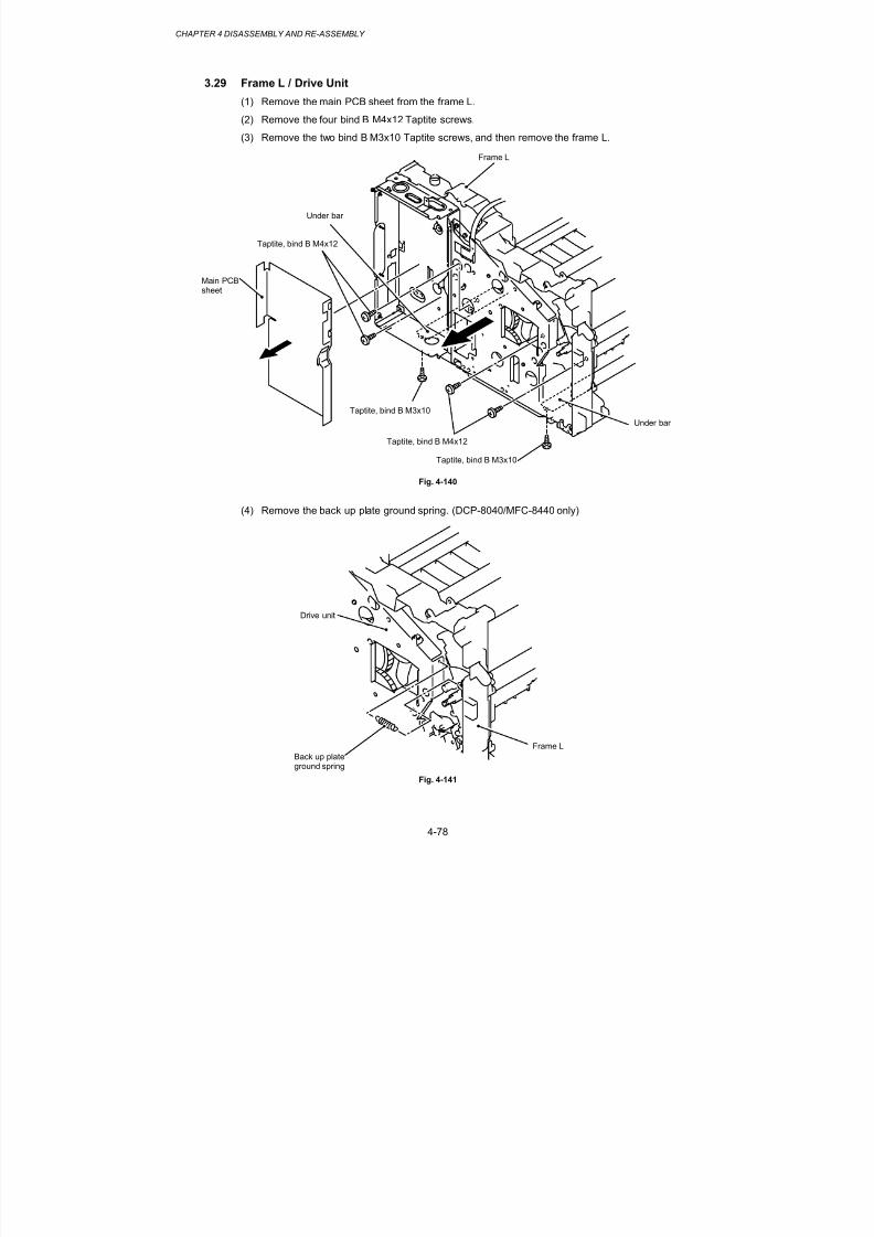
8/9/2019 DCP8040 DCP8045D MFC8440 MFC8840D MFC8840DN Manuales Técnicos.pdf
http://slidepdf.com/reader/full/dcp8040-dcp8045d-mfc8440-mfc8840d-mfc8840dn-manuales-tecnicospdf 159/361
CHAPTER 4 DISASSEMBLY AND RE-ASSEMBLY
4-78
3.29 Frame L / Drive Unit
(1) Remove the main PCB sheet from the frame L.
(2) Remove the four bind B M4x12 Taptite screws.
(3) Remove the two bind B M3x10 Taptite screws, and then remove the frame L.
Fig. 4-140
(4) Remove the back up plate ground spring. (DCP-8040/MFC-8440 only)
Fig. 4-141
Taptite, bind B M3x10
Taptite, bind B M3x10
Under bar
Under bar
Main PCBsheet
Frame L
Frame L
Back up plate
ground spring
Drive unit
Taptite, bind B M4x12
Taptite, bind B M4x12

8/9/2019 DCP8040 DCP8045D MFC8440 MFC8840D MFC8840DN Manuales Técnicos.pdf
http://slidepdf.com/reader/full/dcp8040-dcp8045d-mfc8440-mfc8840d-mfc8840dn-manuales-tecnicospdf 160/361
MFC-8440/8840D/8840DN, DCP-8040/8045D/8045DNSERVICE MANUAL
4-79
(5) Remove the cup S M3x6 Taptite screw.
(6) Remove the ground wire.
(7) Remove the six bind B M4x12 Taptite screws.
(8) Remove the cup S M3x10 Taptite screw.
(9) Remove the cup S M3x6 Taptite screw, and then remove the sub gear plate.
(10) Remove the LD harness 5P from the drive unit.
(11) Remove the drive unit.
(12) Disconnect the connector for the main motor harness from the main motor ASSY.
Fig. 4-142
Taptite, bind B M4x12
Taptite, bind B M4x12
Taptite, cup S M3x6
Taptite, cup S M3x10
Main motor harness
Taptite, cup SM3x6
Sub gear plate
Frame L
Drive unit
Main motor ASSY
Ground wire
LD harness 5P

8/9/2019 DCP8040 DCP8045D MFC8440 MFC8840D MFC8840DN Manuales Técnicos.pdf
http://slidepdf.com/reader/full/dcp8040-dcp8045d-mfc8440-mfc8840d-mfc8840dn-manuales-tecnicospdf 161/361
CHAPTER 4 DISASSEMBLY AND RE-ASSEMBLY
4-80
(13) Remove the four cup S M3x6 Taptite screws, and then remove the main motor ASSY.
(14) Remove the develop joint and joint spring from the drive unit.
(15) Release the two hooks from the
(16) develop joint, and remove the joint stopper.
Fig. 4-143
(17) Remove the gear 40/54Y, gear 17 planetary, gear 45 arm F/R and gear 20 center F/Rfrom the main frame L.
Fig. 4-144
Taptite, cup S M3x6
Main motor ASSY
Drive unit
Taptite, cup S M3x6
Develop joint
Joint stopper
Joint spring
Gear 40/54Y
Gear 17planetary
Gear 20center F/R
Gear 45arm F/R

8/9/2019 DCP8040 DCP8045D MFC8440 MFC8840D MFC8840DN Manuales Técnicos.pdf
http://slidepdf.com/reader/full/dcp8040-dcp8045d-mfc8440-mfc8840d-mfc8840dn-manuales-tecnicospdf 162/361
MFC-8440/8840D/8840DN, DCP-8040/8045D/8045DNSERVICE MANUAL
4-81
(18) Remove the bind B M3x10 Taptite screw.
(19) Remove the P/R solenoid ASSY, the P/R solenoid lever and the solenoid release springP/R.
(20) Remove the bind B M3x10 Taptite screw.
(21) Remove the F/R solenoid ASSY and solenoid release spring F/ R.
Fig. 4-145
(22) Disconnect the connector from the front cover sensor.
(23) Remove the bind B M3x10 Taptite screw.
(24) Remove t
(25) he toner LED PCB unit ASSY.
(26) Remove the sensor clip.
(27) Remove the front cover sensor from the frame L.
Fig. 4-146
Taptite, bind B M3x10
F/R solenoid ASSY
Solenoid release spring P/R
P/R solenoid ASSY
Toner LED PCBunit ASSY
Sensor clip
Front cover sensor
Sensor clip
P/R solenoid lever
Solenoid releasespring F/R
Taptite, bind B M3x10
Taptite, bind B M3x10
Frame L
Front cover sensor
Connector

8/9/2019 DCP8040 DCP8045D MFC8440 MFC8840D MFC8840DN Manuales Técnicos.pdf
http://slidepdf.com/reader/full/dcp8040-dcp8045d-mfc8440-mfc8840d-mfc8840dn-manuales-tecnicospdf 163/361
CHAPTER 4 DISASSEMBLY AND RE-ASSEMBLY
4-82
3.30 Reversing Release Solenoid (MFC-8840D/8840DN, DCP-8045D/8045DN only)
(1) Remove the two bind B M4x12 Taptite screws, and then remove the PCP case.
(2) Remove the two bind B M4x12 Taptite screws, and then remove the eject gear frame unit.
Fig. 4-147
(3) Remove the switch arm return spring and sector gear spring.
(4) Remove the idle gear and switch arm ASSY.
(5) Remove the reversing sector gear and release solenoid lever.
(6) Remove the bind B M3x4 Taptite screw, and then remove the reversing release solenoidand solenoid release spring.
Fig. 4-148
Taptite, bind BM4x12
PCP case
Taptite, bind B M4x12
Eject gear frame unit
Switch arm return spring
Solenoid release spring
Frame L
Idle gear
Hooks
Sector gear spring
Release solenoid lever
Reversing release solenoid
Switch arm ASSY
Reversing sector gear
Hook
Eject gear frame
Taptite, bind B M3x4
Gear A
Gear B

8/9/2019 DCP8040 DCP8045D MFC8440 MFC8840D MFC8840DN Manuales Técnicos.pdf
http://slidepdf.com/reader/full/dcp8040-dcp8045d-mfc8440-mfc8840d-mfc8840dn-manuales-tecnicospdf 164/361
MFC-8440/8840D/8840DN, DCP-8040/8045D/8045DNSERVICE MANUAL
4-83
3.31 Thermistor ASSY
(1) Remove the thermistor ASSY.
Fig. 4-149
3.32 Fan Motor 60 Unit LV / Fan Motor 60 Unit
(1) Remove the fan motor 60 unit LV and the fan motor 60 unit.
Fig. 4-150
Main frame R
Fan motor 60 unit
Fan motor 60 unit LV
Thermistor ASSY
Frame L

8/9/2019 DCP8040 DCP8045D MFC8440 MFC8840D MFC8840DN Manuales Técnicos.pdf
http://slidepdf.com/reader/full/dcp8040-dcp8045d-mfc8440-mfc8840d-mfc8840dn-manuales-tecnicospdf 165/361
CHAPTER 4 DISASSEMBLY AND RE-ASSEMBLY
4-84
3.33 Frame R
(1) Remove the four bind B M4x12 Taptite screws.
(2) Remove the cup S M3x16 Taptite screw.
(3) Remove the two cup S M3x6 Taptite screws.
(4) Remove the main frame R unit.
Fig. 4-151
Taptite, bind B M4x12
Taptite, cup S M3x6
Under bar
Main frame R unit
Under bar
Taptite, cup S M3x6
Taptite, bind B M4x12
Taptite, bind
B M4x12
Taptite, cup S M3x16

8/9/2019 DCP8040 DCP8045D MFC8440 MFC8840D MFC8840DN Manuales Técnicos.pdf
http://slidepdf.com/reader/full/dcp8040-dcp8045d-mfc8440-mfc8840d-mfc8840dn-manuales-tecnicospdf 166/361
MFC-8440/8840D/8840DN, DCP-8040/8045D/8045DNSERVICE MANUAL
4-85
(5) Remove the two bind B M4x12 Taptite screws.
(6) Remove the cup S M3x6 Taptite screw.
(7) Remove the drum spring R.
(8) Remove the FG plate.
Fig. 4-152
(9) Remove the toner sensor PCB unit (Light reception).
Fig. 4-153
Toner sensor PCB unit(Light reception)
Pin
Drum spring R
Taptite, bind B M4x12
Taptite, bind B M4x12
FG plate
Taptite, cup S M3x6
Main frame R
Main frame R

8/9/2019 DCP8040 DCP8045D MFC8440 MFC8840D MFC8840DN Manuales Técnicos.pdf
http://slidepdf.com/reader/full/dcp8040-dcp8045d-mfc8440-mfc8840d-mfc8840dn-manuales-tecnicospdf 167/361
CHAPTER 4 DISASSEMBLY AND RE-ASSEMBLY
4-86
4. PACKING
Fig. 4-154
Machine
Pad
Carton
Telephoneline cord
Pad
Drum unit
Pad
AC power cord
Carton
Carton
ADFsupport
Carton

8/9/2019 DCP8040 DCP8045D MFC8440 MFC8840D MFC8840DN Manuales Técnicos.pdf
http://slidepdf.com/reader/full/dcp8040-dcp8045d-mfc8440-mfc8840d-mfc8840dn-manuales-tecnicospdf 168/361
MFC-8440/8840D/8840DN, DCP-8040/8045D/8045DNSERVICE MANUAL
4-87
5. GUIDELINES FOR LEAD FREE SOLDER
Information on Manually Repairing PCB Soldered with Lead-Free Solder
This document provides information on how to correctly make manual repairs to a printed circuit
board (PCB) soldered with lead-free solder.
1. Characteristics of lead-free solder
Melting point higher than that of conventional tin-lead solder
(Lead-free solder: approx. 220'C, Conventional tin-lead solder: approx. 180'C)
Relatively poor solder wettability and spread (difficult to wet and spread), and hard
Appearance (dull and grainy surface) different from that of conventional solder
Relatively poor wettability, rough surface (bumps are likely to be formed), and solder
dragging
Poor solder elevation
Poor thermal conductivity and heat resistant (difficult to melt)
2. Metal composition & wire solderThe metal composition of lead-free solder allowed for use on PCBs for Brother's products is
following.
LF
Indication
Compositon Manufacturer Origin Name
1 Sn/Ag/Cu Nihon
Genma
Japan DHB-RMA3
NP303
H only
Component-
side
Sn/Ag/Cu Nihon
Genma
Japan DHB-RMA3
NP303
We use wire solder which is indicated by digit after LF indication on PCB.Wire solder made in the contries except Japan are under investigation,and will be evaluated.
3. Appearance quality criteria
The appearance of the surface of portions soldered with lead-free solder is basically the same
as that for those soldered with conventional lead-tin solder, except for the following points.
1) The surface of a portion soldered with lead-free solder is dull and not smooth.
2) Shrinkage cracks can be observed on the surface of a portion soldered with lead-free
solder. (They can be observed using a magnifying glass with approx. 10x
magnification.)
S r n agecracks
Figure 1 Shrinkage Cracks
4. Identification of lead-free solder on PCBs
For PCBs that use lead-free solder, "LF" is indicated by silk-screen printing or attaching a
label. "LF" stands for lead free and indicates that the PCBs bearing such an indication have
been soldered with lead-free solder. A digit is given in a box following "LF" if produced by
silk-screen printing or follows "LF" without a box on an attached label, the digit indicating the
metal composition and wire solder.

8/9/2019 DCP8040 DCP8045D MFC8440 MFC8840D MFC8840DN Manuales Técnicos.pdf
http://slidepdf.com/reader/full/dcp8040-dcp8045d-mfc8440-mfc8840d-mfc8840dn-manuales-tecnicospdf 169/361
CHAPTER 4 DISASSEMBLY AND RE-ASSEMBLY
4-88
5. Precautions for hand soldering operations
1) Soldering operations using lead-free solder are basically the same as those using tin-
lead solder, however, due to the lead-free solder's characteristics of being difficult to
melt, wet, and spread, as well as being hard, a soldering iron needs to be applied for
a longer period of time than when soldering with conventional tin-lead solder. While
soldering is being performed, it must be confirmed that the lead-free solder is
spreading. When solder needs to be added when repairing PCBs, the solder must
only be added after sufficiently melting the previously soldered area. When poor
soldering is repaired, the solder of the poorly soldered area must be sufficiently
removed and lead-free solder newly supplied.
2) Before starting soldering operations, it must be determined whether or not the PCB
has an "LF" indication. If the PCB has an "LF" indication, lead-free solder
corresponding to the digit following "LF" must be used. Conventional solder
including lead (tin-lead solder) must not be used on a PCB that has an "LF" indication.
(Use of tin-lead solder on a PCB having an "LF" indication is prohibited.)
3) A soldering iron for exclusive use with lead-free solder must only be used; a soldering
iron used for soldering with tin-lead solder must not be used with lead-free solder.
The use of soldering irons designed for lead-free solder is desirable (see "7. Soldering
iron" below).4) The requirement for the temperature of the soldering iron’s tip is the same as that for
soldering using conventional solder; the temperature of the soldering iron's tip must
not be raised even though the melting point of the lead-free solder is higher. The
temperature of the soldering iron's tip is restricted to the temperature that the
component to be soldered can resist. It should be noted that the temperature that
the components to be soldered with lead-free solder can resist has not increased
even though the melting point of the solder has.
5) A soldering iron must be correctly applied.
Even though the melting point of the solder has increased, soldering operations must
be performed with the soldering iron’s tip at the same temperature as prescribed
before. Therefore, heat needs to be effectively applied from the tip of the soldering
iron to the base metal. For effective heat application, the shape of the solderingiron's tip and application of the soldering iron (position and angle relative to the base
metal) need to be more strictly controlled than before.
6) The soldered point must be left as it is after the soldering iron is removed for a period
of time longer than that required when soldering is performed with conventional
solder.
The amount of heat applied to the base metal increases due to the higher melting
point of the lead-free solder, and the base metal is heated to higher temperatures.
Consequently, it takes time for the melted solder to cool and to solidify and, therefore,
the soldered area must be left as it is after the soldering iron is removed for a longer
period of time.
7) A localized ventilation system and gloves are required for soldering operations.
Lead-free solder does not contain the toxic substance lead, however, inhalation of the
fumes may adversely affect the health of workers. The silver contained in lead-freesolder is also a toxic substance, though it is not as toxic as lead, and, therefore, a
localized ventilation system and gloves are required for lead-free solder soldering
operations, as required for those with conventional solder.

8/9/2019 DCP8040 DCP8045D MFC8440 MFC8840D MFC8840DN Manuales Técnicos.pdf
http://slidepdf.com/reader/full/dcp8040-dcp8045d-mfc8440-mfc8840d-mfc8840dn-manuales-tecnicospdf 170/361
MFC-8440/8840D/8840DN, DCP-8040/8045D/8045DNSERVICE MANUAL
4-89
6. Soldering irons
When soldering is performed manually using lead-free solder, a soldering iron that has
little reduction in its temperature needs to be used. This refers to a soldering iron that
has a smaller degree of decrease in the temperature at the soldering iron's tip, such as
when the soldering iron is applied to the base metal or solder is supplied, and the
temperature is soon returned to the specified temperature.
With soldering operations using lead-free solder, the requirement for the temperature of
the soldering iron's tip is the same as that for conventional solder, however, the melting
point of lead-free solder is higher than that of conventional solder so productivity will
decrease with conventional soldering irons.
Some tool manufacturers sell soldering irons designed for lead-free solder and that can
maintain the productivity of the soldering operations.
The soldering irons used at BIL are model no. 941 manufactured by HAKKO and M6-SIC-
40 manufactured by BONKOTE. The prices of these soldering irons for use with lead-
free solder are three to four times higher than those for conventional soldering irons with a
temperature controller built in.
7. No mixing of different solders
When repairs are made on a PCB with an "LF" indication on it, lead-free solder with the same metal composition, which is expressed bythe digit following "LF", must be used on a single PCB. For a PCBwith an "LF" indication on it, neither tin-lead solder nor lead-free solderwith a different metal composition must be used.
Compatible solder for each countries are listed below. Solders are freely available from each
manufacturer. Visit the web site below for more detail.
Countries Manufacturer Origin Name Web site
For Japan, UK,
Finland,Germany,
France,
Sweden
ALMIT JAPAN KR-19 SH RMA
LFM-48
http://www.almit.com
For World wide
except
Australia, New
Zealand
KESTER U.S.A. KESTER245
KESTER285
http://www.kester.com
For Worldwide AIM CANADA CASTIN RMA2 http://www.aimsolder.com

8/9/2019 DCP8040 DCP8045D MFC8440 MFC8840D MFC8840DN Manuales Técnicos.pdf
http://slidepdf.com/reader/full/dcp8040-dcp8045d-mfc8440-mfc8840d-mfc8840dn-manuales-tecnicospdf 171/361
CHAPTER 4 DISASSEMBLY AND RE-ASSEMBLY
4-90
6. SCREW TORQUE LIST
1. Main Body
No. Parts code Parts name Location Pcs. Tightening torque
N⋅m (Kgf
⋅cm)
NCU PCB ASSY 2
NCU shield cover 11 087320-616 Taptite, cup S M3x6
NCU shield plate 2
0.686 ±0.098 (7 ±1)
2 087320-616 Taptite, cup S M3x6 Main PCB ASSY 5 0.686 ±0.098 (7 ±1)
2. Cover
No. Parts code Parts name Location Pcs. Tightening torque
N⋅m (Kgf ⋅cm)
Inner chute 4Joint cover front L 21 085412-216 Taptite, bind B M4x12
Joint cover front R 2
0.784 ±0.098 (8 ±1)
2 087311-016 Taptite, cup S M3x10 Driver PCB ASSY 3 0.392 ±0.049 (4 ±0.5)
3 087320-616 Taptite, cup B M3x6 D-PCB shield 1 0.686 ±0.098 (7 ±1)
Joint cover ASSY 4
Side cover R 3
Side cover L 4
Rear cover R 2
Rear cover L MFC 2
Driver PCB access cover 1
4 085412-216 Taptite, bind B M4x12
Rear cover C 1
0.784 ±0.098 (8 ±1)
3. Document Scanner
No. Parts code Parts name Location Pcs. Tightening torque
N⋅m (Kgf ⋅cm)
10A4300-605
Rew, pan (S/P washer)M3
FB motor 20.784 ±0.098 (8 ±1)
2 087320-616 Taptite, cup S M3x6 FG harness 1 0.784 ±0.098 (8 ±1)
3 LE2861-001 Taptite, pan B M3x8 Driver plate ASSY 4 0.490 ±0.098 (5 ±1)
4 UF5034-001 Taptite, B M3x6 Pulley ASSY 1 0.392 ±0.049 (4 ±0.5)
FG plate 35087310-816 Taptite, cup B M3x8
FFC plate 10.490 ±0.098 (5 ±1)
Lock lever B 16UF5034-001 Taptite, B M3x6
Lock lever A 20.392 ±0.049 (4 ±0.5)
7 087411-216 Taptite, cup B M4x12 For the top cover 6 0.784 ±0.098 (8 ±1)
8 087412-016 Taptite, cup B M4x20 For the scanner unit 2 0.784 ±0.098 (8 ±1)

8/9/2019 DCP8040 DCP8045D MFC8440 MFC8840D MFC8840DN Manuales Técnicos.pdf
http://slidepdf.com/reader/full/dcp8040-dcp8045d-mfc8440-mfc8840d-mfc8840dn-manuales-tecnicospdf 172/361
MFC-8440/8840D/8840DN, DCP-8040/8045D/8045DNSERVICE MANUAL
4-91
4. ADF Unit
No. Parts code Parts name Location Pcs. Tightening torque
N⋅m (Kgf ⋅cm)
LF spring 21087311-016 Taptite, cup B M3x10
Hinge arm R 3
0.490 ±0.098 (5 ±1)
20A4300-605
Rew, pan (S/P washer)M3
ADF motor 20.686 ±0.098 (7 ±1)
3 087320-616 Taptite, cup S M3x6 Motor frame 3 0.686 ±0.098 (7 ±1)
4 087311-016 Taptite, cup B M3x10 Paper feed chute 4 0.686 ±0.098 (7 ±1)
ADF chute ASSY 4
Side cover F 15 087311-016 Taptite, cup B M3x10
Side cover R 1
0.490 ±0.098 (5 ±1)
6 UF5034-001 Taptite, B M3x6 Separation rubber 1 0.392 ±0.049 (4 ±0.5)
7 087311-016 Taptite, cup B M3x10 Hinge ASSY L 3 0.588 ±0.098 (6 ±1)
8 087311-016 Taptite, cup B M3x10 Rear sensor cover 2 0.490 ±0.098 (5 ±1)
9 087320-616 Taptite, cup S M3x6 Ground wire 1 0.686 ±0.098 (7 ±1)
5. Panel
No. Parts code Parts name Location Pcs. Tightening torque
N⋅m (Kgf ⋅cm)
Panel PCB ASSY 21 087310-815 Taptite, cup B M3x8
Panel rear cover 60.392 ±0.049 (4 ±0.5)
2 087411-215 Taptite, cup B M4x12 Panel unit 4 0.784 ±0.098 (8 ±1)

8/9/2019 DCP8040 DCP8045D MFC8440 MFC8840D MFC8840DN Manuales Técnicos.pdf
http://slidepdf.com/reader/full/dcp8040-dcp8045d-mfc8440-mfc8840d-mfc8840dn-manuales-tecnicospdf 173/361
CHAPTER 4 DISASSEMBLY AND RE-ASSEMBLY
4-92
7. LUBRICATION
PG4
PG4
PG4
PG4
PG4
PG4
PG4
PG4
PG4
PG4
Shaft idle gear 16Idle gear 16A
Shaft idle gear 16
Idle gear 16A
Drive unit
Gear 58/88
Pendulum gear 22
Flame L
* PG4: Grease PG662 4 mm dia. ballGear 58/88

8/9/2019 DCP8040 DCP8045D MFC8440 MFC8840D MFC8840DN Manuales Técnicos.pdf
http://slidepdf.com/reader/full/dcp8040-dcp8045d-mfc8440-mfc8840d-mfc8840dn-manuales-tecnicospdf 174/361
MFC-8440/8840D/8840DN, DCP-8040/8045D/8045DNSERVICE MANUAL
4-93
EM3
EM3
* EM3: Grease EM-D1103 mm dia. ball
DX feed roller
Tray feed ZL2
Side regist roller ZL2
Side regist roller ZL2

8/9/2019 DCP8040 DCP8045D MFC8440 MFC8840D MFC8840DN Manuales Técnicos.pdf
http://slidepdf.com/reader/full/dcp8040-dcp8045d-mfc8440-mfc8840d-mfc8840dn-manuales-tecnicospdf 175/361
CHAPTER 4 DISASSEMBLY AND RE-ASSEMBLY
4-94
SK4
PG2
* SK4: Grease SK-6234 mm dia. ball
Separation plate ASSY
* PG2: Grease PG-6622 mm dia. ball
Paper feed chute
Rubber holder

8/9/2019 DCP8040 DCP8045D MFC8440 MFC8840D MFC8840DN Manuales Técnicos.pdf
http://slidepdf.com/reader/full/dcp8040-dcp8045d-mfc8440-mfc8840d-mfc8840dn-manuales-tecnicospdf 176/361
MFC-8440/8840D/8840DN, DCP-8040/8045D/8045DNSERVICE MANUAL
4-95
PG4
PG4
LF roller 2 ASSY
Ejection roller ASSY
LF roller 1 ASSY
PF roller holder ASSY
ADF chute ASSY
* PG4: Grease PG662 4 mm dia. ball
* PG4: Grease PG662 4 mm dia. ball
ADF chute ASSY

8/9/2019 DCP8040 DCP8045D MFC8440 MFC8840D MFC8840DN Manuales Técnicos.pdf
http://slidepdf.com/reader/full/dcp8040-dcp8045d-mfc8440-mfc8840d-mfc8840dn-manuales-tecnicospdf 177/361
CHAPTER 4 DISASSEMBLY AND RE-ASSEMBLY
4-96
BG4
ADF motor
ADF chute ASSY
ADF relay PCB ASSY
Motor frame ASSY
* BG4: Grease BG999 4 mm dia. ball

8/9/2019 DCP8040 DCP8045D MFC8440 MFC8840D MFC8840DN Manuales Técnicos.pdf
http://slidepdf.com/reader/full/dcp8040-dcp8045d-mfc8440-mfc8840d-mfc8840dn-manuales-tecnicospdf 178/361
4-97
8. HARNESS ROUTING
Fan motor 60 unit LV
Laser unit (LD harness 5P)
Toner sensor PCB
Toner sensor PCB
Engine PCB
Main PCB Main PCB
Thermistor
Laser unitMP solenoid holder unit
Fan motor 60 unit
Engine PCB
Fan motor 60 unit LV
Engine PCB
1 3Fan motor 60 unit2
5 Main PCB6 MP-PE sensor PCB7

8/9/2019 DCP8040 DCP8045D MFC8440 MFC8840D MFC8840DN Manuales Técnicos.pdf
http://slidepdf.com/reader/full/dcp8040-dcp8045d-mfc8440-mfc8840d-mfc8840dn-manuales-tecnicospdf 179/361

8/9/2019 DCP8040 DCP8045D MFC8440 MFC8840D MFC8840DN Manuales Técnicos.pdf
http://slidepdf.com/reader/full/dcp8040-dcp8045d-mfc8440-mfc8840d-mfc8840dn-manuales-tecnicospdf 180/361
MFC-8440/8840D/8840DN, DCP-8040/8045D/8045DNSERVICE MANUAL
5-1
CHAPTER 5 PERIODIC MAINTENANCE
To avoid creating secondary problems by mishandling, follow the warnings below duringmaintenance work.
WARNING
(1) Always turn of f the power sw itch and unp lug the pow er cord from th e power out le t
before accessing any p ar ts inside the m achine.
(2) Some parts inside the mach ine are extremely ho t imm ediately after the machin e is
used. When opening the front co ver or rear cover to access any par ts inside the
machine, never touch the shaded par ts show n in the fo l lowing f igures.
1. CONSUMABLE PARTS
The consumable parts described in this section are parts which are subject to deterioration ordamage and should be replaced at least once during the period of warranty of the product ifany print quality problem appears.
1.1 Drum Unit
Life expectancy: 20,000 pages
(When printing A4 or Letter size paper at 5% print coverage)
*The actual number of printed pages will vary depending on theaverage type of print job and paper.
NOTE:
• There are many factors that determine the actual drum life, such as temperature, humidity,type of paper, type of toner used, number of pages per print job and so on. Under idealconditions, the average drum life is estimated at up to 20,000 pages. The actual number of pages that your drum will print may be significantly less than this estimate. Because wehave no control over the many factors that determine the actual drum life, we cannotguarantee a minimum number of pages that will be printed by your drum.
• For best performance, use only genuine Brother toner. The machine should be used onlyin a clean, dust-free environment with adequate ventilation.
• Printing with a third-party drum unit may reduce not only the print quality but also thequality and life of the machine itself. Warranty coverage does not apply to problemscaused by the use of third-party drum unit.
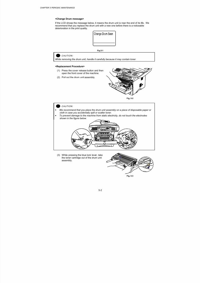
8/9/2019 DCP8040 DCP8045D MFC8440 MFC8840D MFC8840DN Manuales Técnicos.pdf
http://slidepdf.com/reader/full/dcp8040-dcp8045d-mfc8440-mfc8840d-mfc8840dn-manuales-tecnicospdf 181/361
CHAPTER 5 PERIODIC MAINTENANCE
5-2
<Change Drum message>
If the LCD shows the message below, it means the drum unit is near the end of its life. Werecommend that you replace the drum unit with a new one before there is a noticeabledeterioration in the print quality.
Fig.5-1
! CAUTION:
While removing the drum unit, handle it carefully because it may contain toner.
<Replacement Procedure>
(1) Press the cover release button and thenopen the front cover of the machine.
(2) Pull out the drum unit assembly.
Fig. 5-2
! CAUTION:
• We recommend that you place the drum unit assembly on a piece of disposable paper orcloth in case you accidentally spill or scatter toner.
• To prevent damage to the machine from static electricity, do not touch the electrodesshown in the figure below.
(3) While pressing the blue lock lever, takethe toner cartridge out of the drum unitassembly.
Fig. 5-3

8/9/2019 DCP8040 DCP8045D MFC8440 MFC8840D MFC8840DN Manuales Técnicos.pdf
http://slidepdf.com/reader/full/dcp8040-dcp8045d-mfc8440-mfc8840d-mfc8840dn-manuales-tecnicospdf 182/361
MFC-8440/8840D/8840DN, DCP-8040/8045D/8045DNSERVICE MANUAL
5-3
(4) Unpack the new drum unit.
(5) Put the toner cartridge in the new drumunit until you hear it lock into place witha click. When the toner cartridge isinstalled correctly, the blue lock lever islifted automatically. Make sure you fitthe toner cartridge properly, or it mayseparate from the drum unit when youpick up the drum unit assembly. Fig. 5-4
(6) Put the drum unit assembly in the machine.
(7) Reset the drum counter referring to the instructions supplied with the new drum unit.
(8) Press the Clear/Back button.
(9) Press 1 key and when the LCD shows accepted, and close the front cover.
! CAUTION:
• Only unpack a drum unit immediately before you need to install it into the machine. If anunpacked drum unit is subjected to excessive direct sunlight or room light, the unit may bedamaged.
• Handle the drum unit and toner cartridge carefully. If toner scatters on your hands orclothes, wipe or wash it off with cold water immediately.
• Discard the used drum unit according to local regulations, keeping it separate fromdomestic waste. If you have questions, call your local waste disposal office.
• Be sure to seal up the drum unit tightly so that toner powder does not spill out of the unit.
• Do not reset the drum counter when replacing the toner cartridge only.
• It is recommended to clean the machine when you replace the drum unit. Refer tosubsection 3. ‘PERIODICAL CLEANING’ in this Chapter .
1.2 Toner Cartridge
Life expectancy: 6,700 pages / high-yield toner cartridge
3,500 pages / standard cartridge
(When printing A4 or Letter size paper at 5% print coverage)
NOTE:
• There are many factors that determine the actual toner life, such as temperature, humidity,type of paper that you use, the number of pages per print job, etc.
• The amount of toner used varies according to what is printed on the page and the printdensity setting.
• The more that is printed, the more toner will be used.
• If you change the print density setting for lighter or darker printing, the amount of toner thatis used will change
• Wait to unpack the toner cartridge until immediately before you install it in the machine.

8/9/2019 DCP8040 DCP8045D MFC8440 MFC8840D MFC8840DN Manuales Técnicos.pdf
http://slidepdf.com/reader/full/dcp8040-dcp8045d-mfc8440-mfc8840d-mfc8840dn-manuales-tecnicospdf 183/361
CHAPTER 5 PERIODIC MAINTENANCE
5-4
<Toner Low message>
When the toner cartridge is running low, the LCD shows Toner Low.
Fig.5-5
If the LCD shows this message, the toner cartridge has nearly run out of toner. Buy a newtoner cartridge and have it ready before you get a Toner Empty message.
<Toner Empty message>
Fig.5-6
<Replacement Procedure>
(1) Press the cover release button and then open the front cover.
(2) Pull out the drum unit assembly. (Drum unit with toner cartridge).
Fig.5-7
! CAUTION:
• It is recommended to place the drum unit assembly on a piece of disposable paper or clothin case you accidentally spill or scatter toner.
• To prevent damage to the machine from static electricity, do not touch the electrodesshown in the figure below

8/9/2019 DCP8040 DCP8045D MFC8440 MFC8840D MFC8840DN Manuales Técnicos.pdf
http://slidepdf.com/reader/full/dcp8040-dcp8045d-mfc8440-mfc8840d-mfc8840dn-manuales-tecnicospdf 184/361
MFC-8440/8840D/8840DN, DCP-8040/8045D/8045DNSERVICE MANUAL
5-5
(3) Push down the blue lock lever and takethe toner cartridge out of the drum unitassembly.
(4) Unpack the new toner cartridge. Holdthe cartridge level with both hands andgently rock it from side to side five or sixtimes to spread the toner evenly insidethe cartridge. Fig. 5-8
(5) Remove the protective cover.
Fig. 5-9
(6) Put the new toner cartridge firmly intothe drum unit until you hear it lock intoplace. If you put it in properly, the locklever will lift automatically. Make sureyou fit the toner cartridge properly or itmay separate from the drum unit.
Fig. 5-10
(7) Clean the primary corona wire inside the drum unit by gently sliding the blue tab fromright to left several times. Return the tab to the home position before you put the drumunit back in the machine. If you do not, printed pages may have a vertical stripe.
Fig. 5-11
(8) Put the drum unit assembly back in the machine. Close the front cover of the machine.
Home position

8/9/2019 DCP8040 DCP8045D MFC8440 MFC8840D MFC8840DN Manuales Técnicos.pdf
http://slidepdf.com/reader/full/dcp8040-dcp8045d-mfc8440-mfc8840d-mfc8840dn-manuales-tecnicospdf 185/361
CHAPTER 5 PERIODIC MAINTENANCE
5-6
! CAUTION:
• Handle the drum unit and toner cartridge carefully. If toner scatters on your hands orclothes, wipe or wash it off with cold water immediately.
• Be sure to seal the toner cartridge tightly so that toner powder does not spill out of the
cartridge.
• Dispose of the used toner cartridge in accordance with local plastic waste regulations.
• Only unpack a toner cartridge immediately before you need to install it into the machine. Ifa toner cartridge is left unpacked for a long period of time, the toner life is shortened
• If an unpacked drum unit is subjected to excessive direct sunlight or room light, the unitmay be damaged.
• Use a Brother genuine toner cartridge which is specially formulated to ensure top printquality.
• Printing with a 3rd party toner or toner cartridge may reduce not only the printing quality butalso the quality and life of the machine itself. It may also cause serious damage to the performance and life of a genuine Brother drum unit. Warranty cover is not applied to
problems caused by the use of 3rd party toner or toner cartridges.• Brother strongly recommends that you do not refill the toner cartridge provided with the
machine. We also strongly recommend that you continue to use only Genuine BrotherBrand replacement toner cartridges. Using or attempting to use potentially incompatibletoner and/or toner cartridges in the machine may cause damage to the machine itselfand/or it may result in unsatisfactory print quality.
• Make sure that the wire cleaner on the drum unit is returned to the home position ( mark position) before re-installing the drum unit into the machine, or printed pages may havevertical stripes. (Refer to Fig. 5-11.)
• Install the toner cartridge immediately after you remove the protective cover. Do not touchthe development roller and photosensitive drum shaded as shown below;
NOTE:
It is recommended to clean the machine when you replace the toner cartridge. Refer to
subsection 3. ‘PERIODICAL CLEANING’ in this Chapter .

8/9/2019 DCP8040 DCP8045D MFC8440 MFC8840D MFC8840DN Manuales Técnicos.pdf
http://slidepdf.com/reader/full/dcp8040-dcp8045d-mfc8440-mfc8840d-mfc8840dn-manuales-tecnicospdf 186/361
MFC-8440/8840D/8840DN, DCP-8040/8045D/8045DNSERVICE MANUAL
5-7
2. PERIODICAL REPLACEMENT PARTS
Periodical replacement parts are the parts to be replaced periodically to maintain productquality. These parts would affect the product quality greatly if they lost their function even ifthey do not appear to be damaged or there is no change in their appearance.)
The periodical replacement parts listed below should be replaced at the service centerreferring to the service life. For the procedures to replace these parts, refer to CHAPTER 4“DISASSEMBLY AND RE-ASSEMBLY”.
Parts Name Part No. QtyService life
(number of prints)Replacement Procedure
Fixing Unit (115V) LM2579001 1 80,000 pagesSee subsection 3.20 in
CHAPTER 4.
Paper Feeding Kit
(Pad holder ZL2 / Paper
pick-up roller ASSY ZL2)
LM2578001 1 50,000 pagesSee subsection 3.3 and 3.28 in CHAPTER 4.
NOTE:
• The above table shows only estimated values. They are subject to change without priornotice.
• The actual number of printed pages may vary depending on your average type of print joband paper. These figures are based on 5% coverage per page.

8/9/2019 DCP8040 DCP8045D MFC8440 MFC8840D MFC8840DN Manuales Técnicos.pdf
http://slidepdf.com/reader/full/dcp8040-dcp8045d-mfc8440-mfc8840d-mfc8840dn-manuales-tecnicospdf 187/361
CHAPTER 5 PERIODIC MAINTENANCE
5-8
2.1 Fixing Unit
<Disassembly Procedure>
1) Disconnect the AC cord from the machine.
Fig.5-12
2) Close the front cover and pull out the paper tray.
Fig.5-13
Front cover
AC cord
Paper Tray
Machine

8/9/2019 DCP8040 DCP8045D MFC8440 MFC8840D MFC8840DN Manuales Técnicos.pdf
http://slidepdf.com/reader/full/dcp8040-dcp8045d-mfc8440-mfc8840d-mfc8840dn-manuales-tecnicospdf 188/361
MFC-8440/8840D/8840DN, DCP-8040/8045D/8045DNSERVICE MANUAL
5-9
3) Remove the DX feed ASSY.
Fig.5-14
4) Remove the rear cover MP ASSY.
Fig.5-15
Hook
DX feed ASSY
Rear cover MP ASSY

8/9/2019 DCP8040 DCP8045D MFC8440 MFC8840D MFC8840DN Manuales Técnicos.pdf
http://slidepdf.com/reader/full/dcp8040-dcp8045d-mfc8440-mfc8840d-mfc8840dn-manuales-tecnicospdf 189/361
CHAPTER 5 PERIODIC MAINTENANCE
5-10
5) Remove the outer chute MP ASSY.
Fig.5-16
6) Remove the two bind B M4x12 Taptite screws, and then remove the rear cover L.
7) Remove the two bind B M4x12 Taptite screws, and then remove the rear cover R.
Fig.5-17
Taptite, bind B M4x12
Rear cover R
Rear cover LHook
Taptite, bind B M4x12
Hook
Taptite, bind B M4x12
Hook
Outer chute MP ASSY

8/9/2019 DCP8040 DCP8045D MFC8440 MFC8840D MFC8840DN Manuales Técnicos.pdf
http://slidepdf.com/reader/full/dcp8040-dcp8045d-mfc8440-mfc8840d-mfc8840dn-manuales-tecnicospdf 190/361
MFC-8440/8840D/8840DN, DCP-8040/8045D/8045DNSERVICE MANUAL
5-11
8) Remove the two cup S M3x6 Taptite screws, and then remove the NCU unit.
Fig.5-18
9) Disconnect the heater harness and thermistor harness.
10) Remove the bind B M4x12 Taptite screw and the shoulder screw, and then remove thefixing unit.
Fig.5-19
Shoulder screw
Heater harness
Taptite, bind B M4x12
Thermistor harness
Taptite, cup S M3x6
NCU unit
Fixing unit

8/9/2019 DCP8040 DCP8045D MFC8440 MFC8840D MFC8840DN Manuales Técnicos.pdf
http://slidepdf.com/reader/full/dcp8040-dcp8045d-mfc8440-mfc8840d-mfc8840dn-manuales-tecnicospdf 191/361
CHAPTER 5 PERIODIC MAINTENANCE
5-12
<Assembly Procedure>
(1) Mount the fixing unit using the bind B M4x12 Taptite screw and the shoulder screw.
(2) Insert the heater harness and the thermistor harness.
Fig.5-20
(3) Mount the NCU unit using the two cup S M3x6 Taptite screws.
Fig.5-21
Shoulder screw
Heater harness
Taptite, bind B M4x12
Thermistor harness
Fixing unit
Taptite, cup S M3x6
NCU unit

8/9/2019 DCP8040 DCP8045D MFC8440 MFC8840D MFC8840DN Manuales Técnicos.pdf
http://slidepdf.com/reader/full/dcp8040-dcp8045d-mfc8440-mfc8840d-mfc8840dn-manuales-tecnicospdf 192/361
MFC-8440/8840D/8840DN, DCP-8040/8045D/8045DNSERVICE MANUAL
5-13
(4) Mount the rear cover L using the two bind B M4x12 Taptite screws.
(5) Mount the rear cover R using the two bind B M4x12 Taptite screws.
Fig.5-22
(6) Mount the outer chute MP ASSY.
Fig.5-23
Taptite, bind B M4x12
Rear cover R
Rear cover L
Hook
Taptite, bind B M4x12
Hook
Taptite, bind B M4x12
Hook
Outer chute MP ASSY

8/9/2019 DCP8040 DCP8045D MFC8440 MFC8840D MFC8840DN Manuales Técnicos.pdf
http://slidepdf.com/reader/full/dcp8040-dcp8045d-mfc8440-mfc8840d-mfc8840dn-manuales-tecnicospdf 193/361
CHAPTER 5 PERIODIC MAINTENANCE
5-14
(7) Mount the rear cover MP ASSY.
Fig.5-24
(8) Mount the DX feed ASSY.
Fig.5-25
DX feed ASSY
Hook
Rear cover MP ASSY

8/9/2019 DCP8040 DCP8045D MFC8440 MFC8840D MFC8840DN Manuales Técnicos.pdf
http://slidepdf.com/reader/full/dcp8040-dcp8045d-mfc8440-mfc8840d-mfc8840dn-manuales-tecnicospdf 194/361
MFC-8440/8840D/8840DN, DCP-8040/8045D/8045DNSERVICE MANUAL
5-15
(9) Insert the paper tray.
Fig.5-26
(10) Insert the power cord to the machine.
Fig.5-27
Front cover ASSY
Paper Tray
Power cord
Machine

8/9/2019 DCP8040 DCP8045D MFC8440 MFC8840D MFC8840DN Manuales Técnicos.pdf
http://slidepdf.com/reader/full/dcp8040-dcp8045d-mfc8440-mfc8840d-mfc8840dn-manuales-tecnicospdf 195/361
CHAPTER 5 PERIODIC MAINTENANCE
5-16
2.2 Paper Feeding Kit
<Disassembly Procedure>
1) Disconnect the AC cord from the machine.
Fig.5-28
2) Close the front cover and pull out the paper tray.
Fig.5-29
Machine
AC cord
Front cover
Paper tray

8/9/2019 DCP8040 DCP8045D MFC8440 MFC8840D MFC8840DN Manuales Técnicos.pdf
http://slidepdf.com/reader/full/dcp8040-dcp8045d-mfc8440-mfc8840d-mfc8840dn-manuales-tecnicospdf 196/361
MFC-8440/8840D/8840DN, DCP-8040/8045D/8045DNSERVICE MANUAL
5-17
3) Remove the pad holder and the separation pad spring from the paper tray.
Fig.5-30
4) Turn the machine over.
5) Remove the bearing R.
6) Remove the paper pick-up roller ASSY.7) Remove the two roller collars from the paper pick-up roller ASSY.
Fig.5-31
Pad holder
Separation pad spring
Paper pick-up roller ASSY
Bearing R
Roller collar
Roller collar
1
2

8/9/2019 DCP8040 DCP8045D MFC8440 MFC8840D MFC8840DN Manuales Técnicos.pdf
http://slidepdf.com/reader/full/dcp8040-dcp8045d-mfc8440-mfc8840d-mfc8840dn-manuales-tecnicospdf 197/361
CHAPTER 5 PERIODIC MAINTENANCE
5-18
<Assembly Procedure>
(1) Mount the two roller collars to the paper pick-up roller ASSY.
(2) Mount the paper pick-up roller ASSY.
(3) Mount the bearing R.
(4) Turn the machine back to the original orientation.
Fig.5-32
(5) Mount the pad holder and the separation pad spring to the paper tray.
Fig.5-33
Paper pick-up roller ASSY
Bearing R
Roller collar
Roller collar
2
1
Pad holder
Separation pad spring

8/9/2019 DCP8040 DCP8045D MFC8440 MFC8840D MFC8840DN Manuales Técnicos.pdf
http://slidepdf.com/reader/full/dcp8040-dcp8045d-mfc8440-mfc8840d-mfc8840dn-manuales-tecnicospdf 198/361
MFC-8440/8840D/8840DN, DCP-8040/8045D/8045DNSERVICE MANUAL
5-19
(6) Insert the paper tray.
Fig.5-34
(7) Insert the power cord to the machine.
Fig.5-35
Front cover
Paper Tray
Power cord
Machine

8/9/2019 DCP8040 DCP8045D MFC8440 MFC8840D MFC8840DN Manuales Técnicos.pdf
http://slidepdf.com/reader/full/dcp8040-dcp8045d-mfc8440-mfc8840d-mfc8840dn-manuales-tecnicospdf 199/361
CHAPTER 5 PERIODIC MAINTENANCE
5-20
3. PERIODICAL CLEANING
Clean the following parts periodically to avoid any machine problems or print image defects.
! CAUTION: While drum unit and scanner window cleaning basically can be implemented by the end user,the electrical terminals inside the machine and on the drum unit should be cleaned by a servicetechnician. Instruct the users not to touch those terminals.
WARNING
There are high v oltage electrod es inside the machine. Before cleaning the machin e,
make sure that the pow er switch has been turned of f and the pow er cord has been
unplugg ed from the pow er out le t.
3.1 Cleaning the Machine Exterior
Clean the machine exterior to keep the machine clean.
1) Turn off the power switch and unplug the power cord.
2) Wipe dirt and dust away from the machine exterior with a damp cloth and allow themachine to dry completely before turning the power on again.
3) Plug in the power cord.
! CAUTION:
•
Use water or neutral detergents for cleaning. Cleaning with volatile liquids such as thinneror benzene will damage the surface of the machine.
• Do not use cleaning materials that contain ammonia. They will damage the machine andthe toner cartridge.
3.2 Cleaning the Scanner
Turn the machine power switch off and lift the document cover. Clean the scanner glass andglass strip with dry cloth and the white film with isopropyl alcohol on a lint free cloth.
Fig.5-36
White film
Glass stripDocument cover

8/9/2019 DCP8040 DCP8045D MFC8440 MFC8840D MFC8840DN Manuales Técnicos.pdf
http://slidepdf.com/reader/full/dcp8040-dcp8045d-mfc8440-mfc8840d-mfc8840dn-manuales-tecnicospdf 200/361
MFC-8440/8840D/8840DN, DCP-8040/8045D/8045DNSERVICE MANUAL
5-21
Fig.5-37
3.3 Cleaning the Printer
! CAUTION:
• Do not use isopropyl alcohol to remove dirt from the control panel. It many crack the panel.
• Do not use isopropyl alcohol to clean the scanner window or toner sensor.
• Do not touch the scanner window with you finger.
• The drum unit contains toner, so handle it carefully. If toner scatters and you hands orcloths get dirty, immediately wipe or wash it off with cold water.
1) Open the front cover.
2) Remove the drum unit and toner cartridge assembly.
3) Gently clean the scanner window by wiping it with a clean soft dry cloth. Do not useisoproply alcohol.
Fig.5-38
White film
Scanner window

8/9/2019 DCP8040 DCP8045D MFC8440 MFC8840D MFC8840DN Manuales Técnicos.pdf
http://slidepdf.com/reader/full/dcp8040-dcp8045d-mfc8440-mfc8840d-mfc8840dn-manuales-tecnicospdf 201/361
CHAPTER 5 PERIODIC MAINTENANCE
5-22
3.4 Cleaning the Drum Unit
When replacing the drum unit or toner cartridge with a new one, be sure to clean the drum unit.
1) Turn off the power switch and unplug the power cord.
2) Press the cover release button, and then open the front cover.
3) Pull out the drum unit assembly.
! CAUTION:
It is recommended to place the drum unit assembly on a piece of disposable paper or cloth incase you accidentally spill or scatter toner.
4) Clean the primary corona wire inside the drum unit by gently sliding the blue tab fromright to left several times. Return the tab to the home position before re-install the drumunit assembly.
Fig. 5-39
! CAUTION: Make sure that the blue tab on the drum unit is returned to the home position ( mark position)before re-installing the drum unit into the machine, or printed pages may have vertical stripes.
5) Re-install the drum unit into the machine.
6) Close the front cover.
3.5 Cleaning the Scanner Window
When replacing the drum unit or toner cartridge with a new one, be sure to clean the scannerwindow.
1) Turn off the power switch and unplug the power cord.
2) Press the cover release button, and then open the front cover.
3) Pull the drum unit assembly out of the machine.
! CAUTION:
It is recommended to place the drum unit assembly on a piece of disposable paper or cloth incase you accidentally spill or scatter toner.
Home position

8/9/2019 DCP8040 DCP8045D MFC8440 MFC8840D MFC8840DN Manuales Técnicos.pdf
http://slidepdf.com/reader/full/dcp8040-dcp8045d-mfc8440-mfc8840d-mfc8840dn-manuales-tecnicospdf 202/361
MFC-8440/8840D/8840DN, DCP-8040/8045D/8045DNSERVICE MANUAL
5-23
4) Gently wipe the scanner window with a soft dry cloth.
Fig. 5-40
5) Re-install the drum unit assembly into the machine. Close the front cover.
6) Plug in the power cord, and then turn on the power switch.
! CAUTION:
• Handle the drum unit carefully since it contains toner. If toner scatters and your hands orcloths get dirty, immediately wipe or wash it off with cold water.
• Do not touch the scanner window with your fingers.
• Do not wipe the scanner window with isopropyl alcohol.
3.6 Cleaning the Electrical Terminals
To obtain the best print performance, be sure to clean the electrical terminals inside themachine.
1) Turn off the power switch and unplug the power cord.
2) Remove the drum unit from the machine.
3) Wipe the electrical terminals as shown in the figure below with a soft dry cloth.
Fig. 5-41

8/9/2019 DCP8040 DCP8045D MFC8440 MFC8840D MFC8840DN Manuales Técnicos.pdf
http://slidepdf.com/reader/full/dcp8040-dcp8045d-mfc8440-mfc8840d-mfc8840dn-manuales-tecnicospdf 203/361

8/9/2019 DCP8040 DCP8045D MFC8440 MFC8840D MFC8840DN Manuales Técnicos.pdf
http://slidepdf.com/reader/full/dcp8040-dcp8045d-mfc8440-mfc8840d-mfc8840dn-manuales-tecnicospdf 204/361
MFC-8440/8840D/8840DN, DCP-8040/8045D/8045DNSERVICE MANUAL
6-1
CHAPTER 6 TROUBLESHOOTING
1. INTRODUCTION
1.1 Initial Check
(1) Operating environment
Check if:
• The source voltage stays within ±10% from the rated voltage shown on the rating plate.
• The machine is installed on a solid, level surface.
• The room temperature is maintained between 10°C and 32.5°C. The relative humidityis maintained between 20% and 80%.
• The machine is not located in a dusty place.
• The machine is not exposed to ammonia fumes or other harmful gases.
• The machine is not located in a hot or humid area (such as near water or a humidifier).
• The machine is not exposed to direct sunlight.
• The room is well-ventilated.
• The machine is not placed where the ventilation hole of the machine is blocked.
(2) Print paper
Check if :
• A recommended type of print paper is being used. [If the paper is too thick or too thin,or tends to curl, paper jams or paper feed problems may occur, or printed images may
be blurred.]
• The print paper is damp. [If so, use fresh paper, and check whether the print qualityimproves or not.]
• The print paper is short-grained paper or acid paper. [If so, print quality problems mayoccur.]
For further information on paper, refer to subsection 2.12 ‘Paper’ in CHAPTER 1.
(3) Consumable parts
Check if:
• The LCDs on the machine control panel indicate “Toner Empty”. If the LCDs indicate“Toner Empty”, replace the cartridge with a new one.
For further information on consumable parts, refer to 1. ‘CONSUMABLE PARTS’ inCHAPTER 5.

8/9/2019 DCP8040 DCP8045D MFC8440 MFC8840D MFC8840DN Manuales Técnicos.pdf
http://slidepdf.com/reader/full/dcp8040-dcp8045d-mfc8440-mfc8840d-mfc8840dn-manuales-tecnicospdf 205/361
CHAPTER 6 TROUBLESHOOTING
6-2
(4) Others
Condensation:
When the machine is moved from a cold room into a warm room in cold weather,condensation may occur inside the machine, causing various problems as listed below:
• Condensation on the optical surfaces such as the scanning mirror, lenses, the reflectionmirror and the protection glass may cause the print image to be light.
• If the photosensitive drum is cold, the electrical resistance of the photosensitive layer isincreased, making it impossible to obtain the correct contrast when printing.
• Condensation on the corona unit may cause corona charge leakage.
• Condensation on the hopper plate and separation pad may cause paper feed troubles.
If condensation has occurred, print several pages or leave the machine for 2 hours to allow it toreach room temperature.
If the drum unit is unpacked soon after it is moved from a cold room to a warm room,condensation may occur inside the unit, which may cause incorrect images. Instruct the userto allow the unit to come to room temperature before unpacking it. This will take one or two
hours.
1.2 Warnings for Maintenance Work
To avoid creating secondary problems by mishandling, follow the warnings below duringmaintenance work.
WARNING
(1) Always turn of f the power sw itch and unp lug the pow er cord from th e power out le t
before accessing any p ar ts inside the m achine.
(2) Some parts inside the mach ine are extremely ho t imm ediately after the machin e is
used. When opening the front co ver or rear cover to access any par ts inside themachine, never touch the shaded par ts show n in the fo l lowing f igures.

8/9/2019 DCP8040 DCP8045D MFC8440 MFC8840D MFC8840DN Manuales Técnicos.pdf
http://slidepdf.com/reader/full/dcp8040-dcp8045d-mfc8440-mfc8840d-mfc8840dn-manuales-tecnicospdf 206/361
6-3
1.3 Identify the Problem
If you encounter any machine error or problem, first identify it referring to the chart below, then see the appropria
NOTE:
The following troubleshooting sections contain both the actions which users should take or check and the ones perform.
10. Network Problems
3.3
3.4
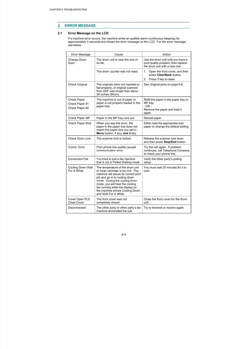
8/9/2019 DCP8040 DCP8045D MFC8440 MFC8840D MFC8840DN Manuales Técnicos.pdf
http://slidepdf.com/reader/full/dcp8040-dcp8045d-mfc8440-mfc8840d-mfc8840dn-manuales-tecnicospdf 207/361
CHAPTER 6 TROUBLESHOOTING
6-4
2. ERROR MESSAGE
2.1 Error Message on the LCD
If a machine error occurs, the machine emits an audible alarm (continuous beeping) for
approximately 4 seconds and shows the error message on the LCD. For the error message,see below.
Error Message Cause Action
The drum unit is near the end ofits life.
Use the drum unit until you have aprint quality problem; then replacethe drum unit with a new one.
Change DrumSoon
The drum counter was not reset. 1. Open the front cover, and then
press Clear/Back button.
2. Press 1 key to reset.
Check Original The originals were not inserted orfed properly, or original scannedfrom ADF was longer than about36 inches (90cm).
See Original jams on page 6-8.
Check Paper
Check Paper #1
Check Paper #2
The machine is out of paper orpaper is not properly loaded in thepaper tray.
Refill the paper in the paper tray orMP tray.- OR -Remove the paper and load itagain.
Check Paper MP Paper in the MP tray runs out. Reload paper.
Check Paper Size When you see this error, thepaper in the paper tray does not
match the paper size you set inMenu button, 1 key, and 3 key.
Either load the appropriate sizepaper or change the default setting.
Check Scan Lock The scanner lock is locked. Release the scanner lock lever,
and then press Stop/Exit button.
Comm. Error Poor phone line quality causedcommunication error.
Try the call again. If problemcontinues, call Telephone Companyto check your phone line.
Connection Fail You tried to poll a fax machinethat is not in Polled Waiting mode.
Verify the other party’s pollingsetup.
Cooling Down WaitFor A While
The temperature of the drum unitor toner cartridge is too hot. Themachine will pause its current print
job and go in to cooling downmode. During the cooling downmode, you will hear the coolingfan running while the display onthe machine shows Cooling Down,and Wait For A While.
You must wait 20 minutes for it tocool.
Cover Open PLSClose Cover
The front cover was notcompletely closed.
Close the front cover for the drumunit.
Disconnected The other party or other party’s faxmachine terminated the call.
Try to transmit or receive again.

8/9/2019 DCP8040 DCP8045D MFC8440 MFC8840D MFC8840DN Manuales Técnicos.pdf
http://slidepdf.com/reader/full/dcp8040-dcp8045d-mfc8440-mfc8840d-mfc8840dn-manuales-tecnicospdf 208/361
MFC-8440/8840D/8840DN, DCP-8040/8045D/8045DNSERVICE MANUAL
6-5
Error Message Cause Action
DX Lever Error The paper adjustment lever forduplex printing is not correctly setfor the paper size.
Set the duplex lever to the correctposition.
Fuser Open The fuser cover is open. Please close the jam clear cover.
(See Paper Jam on page 6-13.)
Machine Error XX Machine has a mechanicalproblem.
Refer to ‘2.2 Error Codes Shown inthe “MACHINE ERROR X X”message’.
Out of Memory You can’t store data in thememory.
(Fax sending in process)
Press Stop button and wait until theother operations in progress finishand then try again.- OR -Clear the data in the memory.
(Copy operation in process)
Press Stop button and wait until theother operations in process finishand then try again.- OR -Clear the data in the memory.- OR -
Add an optional memory.
(Printing operation in process)Reduce print resolution.- OR -Clear the data in the memory.- OR -
Add an optional memory.
NoResponse/Busy
The number you dialed does notanswer or is busy.
Verify the number and try again.
NotRegistered
You tried to access a One-Touchor Speed-Dial number that is notprogrammed.
Set up the One-Touch or Speed-Dial number.
PLS Open Cover A page, piece of paper or paperclip, etc. may be jammed insidethe machine.
Open the front cover. If you seeany jammed paper or other item,gently pull it out, then close thefront cover. If the error messageremains, open and close the frontcover again. If the machine cannot
reset itself and return to the dateand time prompt, it will displayMachine Error XX.Refer to ‘2.2 Error Codes Shown inthe “MACHINE ERROR X X”message’.

8/9/2019 DCP8040 DCP8045D MFC8440 MFC8840D MFC8840DN Manuales Técnicos.pdf
http://slidepdf.com/reader/full/dcp8040-dcp8045d-mfc8440-mfc8840d-mfc8840dn-manuales-tecnicospdf 209/361
CHAPTER 6 TROUBLESHOOTING
6-6
Error Message Cause Action
No DX Tray You tried to make duplexprinting with duplex coveropen.
Install the duplex tray correctly.(See Paper is jammed in the duplex tray(For MFC-8840D/8840DN,DCP-8045D/8045DN) on page 6-16.)
Paper Jam The paper is jammed in themachine.
See Paper Jam on page 6-13 or Paperis jammed in the Duplex Tray (For MFC-8840D/8840DN, DCP-8045D/8045DN)on page 6-16.
Toner Empty Toner cartridge is notinstalled.- OR -Toner is used up and printingis not possible.
Reinstall the toner cartridge.
- OR -
Replace the toner cartridge with a newone.
Toner Low If the LCD shows Toner Low,you can still print.
But the toner is depleted andthe machine is telling you thatthe toner will soon run out.
Order a new toner cartridge now.

8/9/2019 DCP8040 DCP8045D MFC8440 MFC8840D MFC8840DN Manuales Técnicos.pdf
http://slidepdf.com/reader/full/dcp8040-dcp8045d-mfc8440-mfc8840d-mfc8840dn-manuales-tecnicospdf 210/361
MFC-8440/8840D/8840DN, DCP-8040/8045D/8045DN SERVICE MANUAL
6-7
2.2 Error Codes Shown in the “MACHINE ERROR X X” message.
If the LCD shows the "PLS OPEN COVER" message, you can display the detailed error codefollowing the MACHINE ERROR, by using the maintenance-mode function code 82 describedin Chapter 7, Section 3.16.
NOTE:
• When checking a PCB as instructed in the "Check:" column, check its harness also.
• To check sensors, use the maintenance-mode function code 32 described in Chapter 7,Section 3.9 (that is, press the 3 and 2 keys in the maintenance mode).
Error Code(Hex)
Error factor Check:
56 MP front cover opened. • MP front cover
57 Recording paper jam (inside DX unit). • DX unit
58
Reserved
(Recording paper jam (no DX unit)).
• DX unit
59Reserved
(Recording paper jam (inside MP tray)).
• MP tray
5AReserved
(Out of recording paper).
• Recording paper
5BReserved (Paper size error in case of
double-sided print).
• Recording paper
5CReserved (Paper size error of one side only
in case of double-sided print).
5DReserved
(MP tray sensor remains ON).
• MP tray sensor
5E
Reserved
(MP tray sensor remains OFF).
• MP tray sensor
5FReserved
(DX unit sensor is inactivated).
• DX unit sensor
6AHeater warming-up timeout error.
(Heater does not reach 60°C within 11 sec.)
• Thermistor ASSY
• Halogen lamp
6B
Heater warming-up timeout error.
(Heater does not reach 100°C within 15
sec.)
• Thermistor ASSY
• Halogen lamp
6C
Heater temperature exceeds the maximum
high temperature.
(270°C or more is detected for 1 sec.)
• Thermistor ASSY
• Power supply PCB
6D
Heater temperature lowers the minimum
low temperature.(60°C or less is detected for 1 sec.)
• Thermistor ASSY
• Power supply PCB
6E
Heater temperature does not go up enough.
(Slower temperature rise rate than 2°C/5
sec. is detected.)
• Halogen lamp
• Power supply PCB
6FHeater hard limiter operates. • Thermistor ASSY
• Power supply PCB
71Scanner motor does not synchronize with
the reference clock.
• Scanner motor
72Cannot detect Beam Detect signal. • Scanner motor
• MP tray open sensor

8/9/2019 DCP8040 DCP8045D MFC8440 MFC8840D MFC8840DN Manuales Técnicos.pdf
http://slidepdf.com/reader/full/dcp8040-dcp8045d-mfc8440-mfc8840d-mfc8840dn-manuales-tecnicospdf 211/361
CHAPTER 6 TROUBLESHOOTING
6-8
Error Code(Hex)
Error factor Check:
73Drum unit is not mounted. • Toner sensor
•
Drum unit
74Toner empty. • Toner sensor
• Toner cartridge
75 In-casing temperature error. • Thermistor ASSY
76Heater harness disconnected or broken. • Thermistor ASSY
• Halogen lamp
78Heater thermistor harness disconnected or broken.
• Thermistor ASSY
79In-casing temperature sensor harnessdisconnected or broken.
7AMain motor does not synchronize with thereference clock.
7B ASIC error on the main PCB.
7C Engine PCB error.
• Thermistor ASSY
• Main PCB
• Engine PCB• Main motor
80 At the start of recording operation, thecontroller detects that paper is smaller than A4 size in length or width.
• Paper size
• Front registration sensor
81 Paper jam. • Jammed paper
82 Paper feeding error. • Paper pick up roller
83Recording paper jam.(At the retry of paper pulling-in operation,the registration sensor is not OFF.)
• Registration sensor • Main PCB
84
Recording paper jam.(The paper width sensor and/or registrationsensor has detected a paper jam.)
• Registration sensor actuator
• If the paper width sensor isdefective, replace the needle tube& head flat cable ASSY.
• Main PCB
85 No paper cassette loaded.
86 No 2nd paper cassette loaded.
87Main motor stop position error. •
Main motor
88
Recording paper jam.(Even after paper pulling-in operation, theregistration sensor is still OFF.)
• Registration sensor actuator
• If the paper width sensor isdefective, replace the needle tube& head flat cable ASSY.
• Main PCB
A1Front cover opened. • Front cover sensor
• Main PCB

8/9/2019 DCP8040 DCP8045D MFC8440 MFC8840D MFC8840DN Manuales Técnicos.pdf
http://slidepdf.com/reader/full/dcp8040-dcp8045d-mfc8440-mfc8840d-mfc8840dn-manuales-tecnicospdf 212/361
MFC-8440/8840D/8840DN, DCP-8040/8045D/8045DNSERVICE MANUAL
6-9
ErrorCode(Hex)
Error factor Check:
A2 Document too long to scan.
A3
Document not detected by the document
rear sensor.
• Document front sensor
• Document rear sensor
• Document sensor PCB• Document feed roller
• ADF motor
• Main PCB
AAThe document cover is not closed. Remove the document and close the
document cover.
AE The CCD HP sensor will not come ON.
AFThe CCD HP sensor will not go OFF.
• CCD unit
• CCD flat cable
• Driver PCB
• Main PCB
B0 Reading motor half inserted. • Reading motor harness
B1Dark level offset data level error forscanning.
B2 Gain control data level error for scanning.
• CCD unit
• Main PCB
B3 Scan area left edge detection error.
B4
Scan area right edge detection error.
• CCD unit
• Main PCB
• Black markings on the white-levelreference film inside the scannertop cover
B5Horizontal scanning edge reductiondetection error in scanning area setting.
B6 Horizontal scanning edge enlargementdetection error in scanning area setting.
BB
White level data error. • CCD unit
• CCD flat cable
• Driver PCB
BDBlack level data error. • CCD unit
• Main PCB
BE
Scan starting edge detection error. • CCD unit
• CCD flat cable
• Driver PCB
• Black markings on the white-level
reference film inside the scannertop cover
D* Modem error. • Main PCB
E4
Out of recording paper. • ASF
• Registration sensor
• Main PCB
E6 Write error in EEPROM. • Driver PCB
E8 Data scanning error during transmission.
EA Document removed at phase B.
• CCD unit
• Main PCB

8/9/2019 DCP8040 DCP8045D MFC8440 MFC8840D MFC8840DN Manuales Técnicos.pdf
http://slidepdf.com/reader/full/dcp8040-dcp8045d-mfc8440-mfc8840d-mfc8840dn-manuales-tecnicospdf 213/361
CHAPTER 6 TROUBLESHOOTING
6-10
ErrorCode(Hex)
Error factor Check:
F5 Internal software error. • Replace the main PCB if this erroroccurs frequently.
F6 PC interface error. • Interface cable• Main PCB
FA Reading motor error detected. • Reading motor
FF Memory management error. • Replace the main PCB if this erroroccurs frequently.

8/9/2019 DCP8040 DCP8045D MFC8440 MFC8840D MFC8840DN Manuales Técnicos.pdf
http://slidepdf.com/reader/full/dcp8040-dcp8045d-mfc8440-mfc8840d-mfc8840dn-manuales-tecnicospdf 214/361
MFC-8440/8840D/8840DN, DCP-8040/8045D/8045DNSERVICE MANUAL
6-11
3. PAPER PROBLEMS
3.1 Paper Loading Problems
First, make sure that you are using paper that meets Brother recommended paper
specifications. See 2.12 Paper in Chapter 1.
Problem Remedy
The machine does not feedpaper.
• If there is paper in the paper tray, make sure it is straight. Ifthe paper is curled, you should straighten it before printing.Sometimes it is helpful to remove the paper, turn the stackover and put it back in the paper tray.
• Reduce the amount of paper in the paper tray, and then tryagain.
• Check that manual feed mode is not selected in the printerdriver.
The machine does not feed
paper from the manual feedslot.
• Re-insert the paper firmly, one sheet at a time.
• Make sure that manual feed mode is selected in the printerdriver.
The machine will not feedenvelopes.
• The machine can feed envelopes from the manual feedtray or multi-purpose tray. Your application software mustbe set up correctly to print on the envelope size you areusing. This is usually done in the page setup or documentsetup menu of your software. Please see your softwareapplication manual.
A paper jam has occurred. • Clear the jammed paper. Please see paper jams and howto clear them or the paper jam instructional video on theCD-ROM.
The machine does not printinto the top output tray.
• Close the back output tray.
The machine does not print onthe specified paper.(with optional lower tray unit)
• Make sure that the appropriate printer driver is selected.
The back light not light upappears although documentsare set.
• Check the sensors by using the maintenance-modefunction code 32. (Refer to Chapter 7, Subsection 3.9)
• Check the document front sensor actuator and documentrear sensor actuator.
• Check the main PCB.
Document not fed. • Check the ADF and its related sections.
• Check the ADF motor and its harness.
• Check the document feed roller and its related gears.
• Check the main PCB.
Document double feeding. • Check the ADF parts.
Document jam. • Check the ADF motor.

8/9/2019 DCP8040 DCP8045D MFC8440 MFC8840D MFC8840DN Manuales Técnicos.pdf
http://slidepdf.com/reader/full/dcp8040-dcp8045d-mfc8440-mfc8840d-mfc8840dn-manuales-tecnicospdf 215/361
CHAPTER 6 TROUBLESHOOTING
6-12
3.2 Original Jams
Based upon where the original or printed sheet is jammed, follow the appropriate set ofinstructions to remove it.
3.2.1 Original is jammed in the top of the ADF unit
(1) Take out any paper from the ADF that is not jammed.
(2) Lift the ADF cover.
(3) Pull the jammed original out to the right.
(4) Close the ADF cover.
(5) Press Stop/Exit button.
Fig. 6-1
3.2.2 Original is jammed inside the ADF unit
(1) Take out any paper from the ADF that is not jammed.
(2) Lift the document cover.
(3) Pull the jammed original out to the right.
(4) Close the document cover.
(5) Press Stop/Exit button.
Fig. 6-2
-OR-
(1) Remove the ADF support out of the ADF unit.
(2) Pull the jammed original out to the right.
(3) Press Stop/Exit button.
Fig. 6-3

8/9/2019 DCP8040 DCP8045D MFC8440 MFC8840D MFC8840DN Manuales Técnicos.pdf
http://slidepdf.com/reader/full/dcp8040-dcp8045d-mfc8440-mfc8840d-mfc8840dn-manuales-tecnicospdf 216/361
MFC-8440/8840D/8840DN, DCP-8040/8045D/8045DNSERVICE MANUAL
6-13
3.3 Paper Jams
3.3.1 Clearing jammed paper
Clear the jammed paper following the procedures below;
(1) Pull the paper tray completely out of the machine.
(2) Pull the jammed paper up and out of the machine.
Fig. 6-4
(3) Press the cover release button and then open the front cover.
(4) Pull out the drum unit assembly. Pull the jammed paper up and out of the machine. If youcannot remove the drum unit assembly easily at this time, do not use extra force. Instead,pull the edge of the jammed paper from the paper tray.
Fig. 6-5

8/9/2019 DCP8040 DCP8045D MFC8440 MFC8840D MFC8840DN Manuales Técnicos.pdf
http://slidepdf.com/reader/full/dcp8040-dcp8045d-mfc8440-mfc8840d-mfc8840dn-manuales-tecnicospdf 217/361
CHAPTER 6 TROUBLESHOOTING
6-14
! CAUTION:
To prevent damage to the machine caused by static electricity, do not touch the electrodesshown in Figure 6-6.
Fig. 6-6
(5) Open the back output tray. Pull the jammed paper out of the fuser unit. If the paper jamcan be cleared, go to Step 7.
Fig. 6-7
NOTE:
If you have to pull the paper toward the back of the machine, the fuser may get dirty with toner powder and it may scatter on the next printouts. Print a few copies of the test page until thescattering of toner stops.
! CAUTION:
After you have just used the machine, some internal parts of the machine are extremely hot!Wait for the machine to cool down before you touch the internal parts of the machine.
Fig. 6-8

8/9/2019 DCP8040 DCP8045D MFC8440 MFC8840D MFC8840DN Manuales Técnicos.pdf
http://slidepdf.com/reader/full/dcp8040-dcp8045d-mfc8440-mfc8840d-mfc8840dn-manuales-tecnicospdf 218/361
MFC-8440/8840D/8840DN, DCP-8040/8045D/8045DNSERVICE MANUAL
6-15
(6) Open the jam clear cover. Pull the jammed paper out of the fuser unit.
Fig. 6-9
(7) Close the jam clear cover. Close the back output tray.(8) Push the lock lever down and take the toner cartridge out of the drum unit assembly. Take
out the jammed paper if there is any inside the drum unit.
Fig. 6-10
(9) Put the drum unit assembly back in the machine.
(10) Put the paper tray in the machine.
(11) Close the front cover.

8/9/2019 DCP8040 DCP8045D MFC8440 MFC8840D MFC8840DN Manuales Técnicos.pdf
http://slidepdf.com/reader/full/dcp8040-dcp8045d-mfc8440-mfc8840d-mfc8840dn-manuales-tecnicospdf 219/361

8/9/2019 DCP8040 DCP8045D MFC8440 MFC8840D MFC8840DN Manuales Técnicos.pdf
http://slidepdf.com/reader/full/dcp8040-dcp8045d-mfc8440-mfc8840d-mfc8840dn-manuales-tecnicospdf 220/361
MFC-8440/8840D/8840DN, DCP-8040/8045D/8045DNSERVICE MANUAL
6-17
3.3.3 Causes & countermeasures
The causes for paper jam problems vary depending on the location of the paper jam. When apaper jam occurs inside the machine, you have to find the location of the paper jam first,remove the jammed paper and then take the appropriate countermeasure referring to the tablebelow;
Problem Type of Jam Cause Remedy
Jam when themachine is turnedon.
Paper stuck The front registrationsensor or paper ejectsensor is turned on.
Remove the paperinside the machine.If there is no paper,check the suspectsensors referring to‘3.9 SensorOperationaI Check’in Chapter 7.
Top of paperstopped at 350mm
from the second exitroller. Next paper isnot fed.
Jam caused bypaper length
detected as longerthan 400mm (16 in).
The front registrationsensor is not
returning properlyand is not turning off.
Check frontregistration sensor
motion referring to‘3.9 SensorOperationaI Check’in Chapter 7.
Bottom of paperstopped around thetransfer roller.
Jam caused bypaper lengthdetected as shorterthan 80mm.
The front registrationsensor was turnedoff early.Malfunction ofactuator or hardwarenoise.
Check the frontregistration sensorreferring to ‘3.9Sensor OperationaICheck’ in Chapter 7.
Top of paperstopped between the
paper feed roller andthe pick-up roller.
Jam caused by apaper feed delay.
Paper was not fed inat the proper timing
due to paper dust orwear of the rubberpick-up roller.
Remove the paperdust attached to the
pick-up roller. If therubber is worn out,replace it with a newone.
Top of paperstopped at 50mmfrom the contactpoint of the heatroller and pressureroller.
Jam caused by thepaper not beingsensed when ejectedfrom the paper ejectsensor.
The paper ejectsensor is not workingproperly and has notturned off. (singleprinting)
Check sensor motionreferring to ‘3.9Sensor OperationaICheck’ in Chapter 7.
Jam after paper isejected.
Jam caused by thepaper not beingsensed when ejectedfrom the paper ejectsensor.
The paper ejectsensor or frontregistration sensor isnot working properlyand has not turnedoff. (continuousprinting)
Check sensor motionreferring to ‘3.9Sensor OperationaICheck’ in Chapter 7.

8/9/2019 DCP8040 DCP8045D MFC8440 MFC8840D MFC8840DN Manuales Técnicos.pdf
http://slidepdf.com/reader/full/dcp8040-dcp8045d-mfc8440-mfc8840d-mfc8840dn-manuales-tecnicospdf 221/361
CHAPTER 6 TROUBLESHOOTING
6-18
3.4 Paper Feeding Problems
Even if the paper is printed and ejected without any problems such as paper jams, paperfeeding problems below may appear.
Users can clear these problems by following the ‘User Check’ items for each problem. Even ifthe same problem occurs again, follow the procedures in the table below.
F-1 Double feeding
User Check
Check the paper used meets the recommended paper specifications.
Possible cause Step Check Result Remedy
Separation pad 1 Is the surface of the separationpad worn out?
Yes Replace the separation pad.
F-2 Wrinkles or creases
User Check
(1) Check that paper is loaded into the paper tray correctly.
(2) Check the paper used meets the recommended paper specifications.
(3) Try printing using the straight-through output path.
(4) Turn over the stack of paper in the cassette or try rotating the paper 180° in the cassette.
Possible cause Step Check Result Remedy
Paper 1 Is the problem solved if newpaper is used?
Yes Instruct the user how to storepaper so that it does notabsorb moisture.
Fixing unitentrance guide
2 Is the entrance guide dirty? Yes Clean the entrance guide.
Fixing unit 3 Is the pressure roller dirty? Yes Clean the pressure roller.
No Replace the fixing unit.
F-3 Page skew
User Check
(1) Check that the paper or other media is loaded into the paper tray correctly and that the paperguides are not too tight or too loose against the paper stack.
(2) If using the manual feed slot, check how to load paper into the manual feed slot correctly.
(3) The paper tray may be too full. Load paper below 27mm in depth.
(4) Check the paper used meets the recommended paper specifications.

8/9/2019 DCP8040 DCP8045D MFC8440 MFC8840D MFC8840DN Manuales Técnicos.pdf
http://slidepdf.com/reader/full/dcp8040-dcp8045d-mfc8440-mfc8840d-mfc8840dn-manuales-tecnicospdf 222/361
MFC-8440/8840D/8840DN, DCP-8040/8045D/8045DNSERVICE MANUAL
6-19
F-4 Curl or Wave
User Check
(1) Check the paper used meets the recommended paper specifications. Both high temperature andhumidity will cause paper to curl.
(2) If the machine is used infrequently, the paper may have sat for too long in the paper tray . Turnover the stack of paper in the paper tray . Also, try rotating the paper 180° in the paper tray .
(3) Try printing using the straight-through output path.
NOTE:
For no paper supplied as the cause of a malfunction, see M-4 ‘No paper supplied’ in 6.‘MALFUNCTIONS’ in this Chapter.

8/9/2019 DCP8040 DCP8045D MFC8440 MFC8840D MFC8840DN Manuales Técnicos.pdf
http://slidepdf.com/reader/full/dcp8040-dcp8045d-mfc8440-mfc8840d-mfc8840dn-manuales-tecnicospdf 223/361
CHAPTER 6 TROUBLESHOOTING
6-20
4. SOFTWARE SETTING PROBLEMS
The machine may not print the data correctly if there are incorrect software settings.
S-1 “There was an error writing to LPT1: (or BRUSB) for the machine” error messageappears.
User Check
(1) Check that the printer cable is not damaged or broken. Check also that the cable is connectedto the correct interface connectors of both the machine and PC.
(2) Check that the correct machine is selected if you have an interface switching device.
(3) Check that the appropriate printer driver is selected as ‘Set as Default’. Check also that thecorrect print port is set for the selected printer driver.
(4) Check that the machine is not connected to the same port which is also connected to a mass
storage device or scanner. Remove all other devices and connect the port to the machine only.Turn off the printer status monitor in the device options tab in the printer driver.
(5) If the print port is set as an ECP port, change it to a normal port.
(6) Try resetting the factory settings.
Possible cause Step Check Result Remedy
Main PCBfailure
1 Is it possible to print withanother PC and printer cable?
No Replace the main PCB.
Yes This problem may appearunder the specified systemenvironment. Check the
environment which the userused.

8/9/2019 DCP8040 DCP8045D MFC8440 MFC8840D MFC8840DN Manuales Técnicos.pdf
http://slidepdf.com/reader/full/dcp8040-dcp8045d-mfc8440-mfc8840d-mfc8840dn-manuales-tecnicospdf 224/361
MFC-8440/8840D/8840DN, DCP-8040/8045D/8045DNSERVICE MANUAL
6-21
S-3 Although the USB driver is installed, it is unable to find the BRUSB: port.(Windows98/Me only)
User Check
(1) Re-install, according to the instruction of the subsection 3.2 in Chapter 2.
(2) Try to connect the machine directly to the computer if it is connected through a USB hub.
Possible cause Step Check Result Remedy
ComputerOperatingSystem
1 Windows 95 or WindowsNT4.0?
Yes Not supported.
Computersettings
2 Does ‘Universal Serial BusControllers’ appear in theDevice Manager tab of ‘SystemProperties’ in Control Panel?
No This problem can be causedby your computer settings.See the computer manual.
USB cable/machinedamage
3 Does “Add New HardwareWizard” appears on the screenor Does test print complete?
No The USB cable is damaged.Replace the cable. If thesame problem appears, themachine will be damaged.
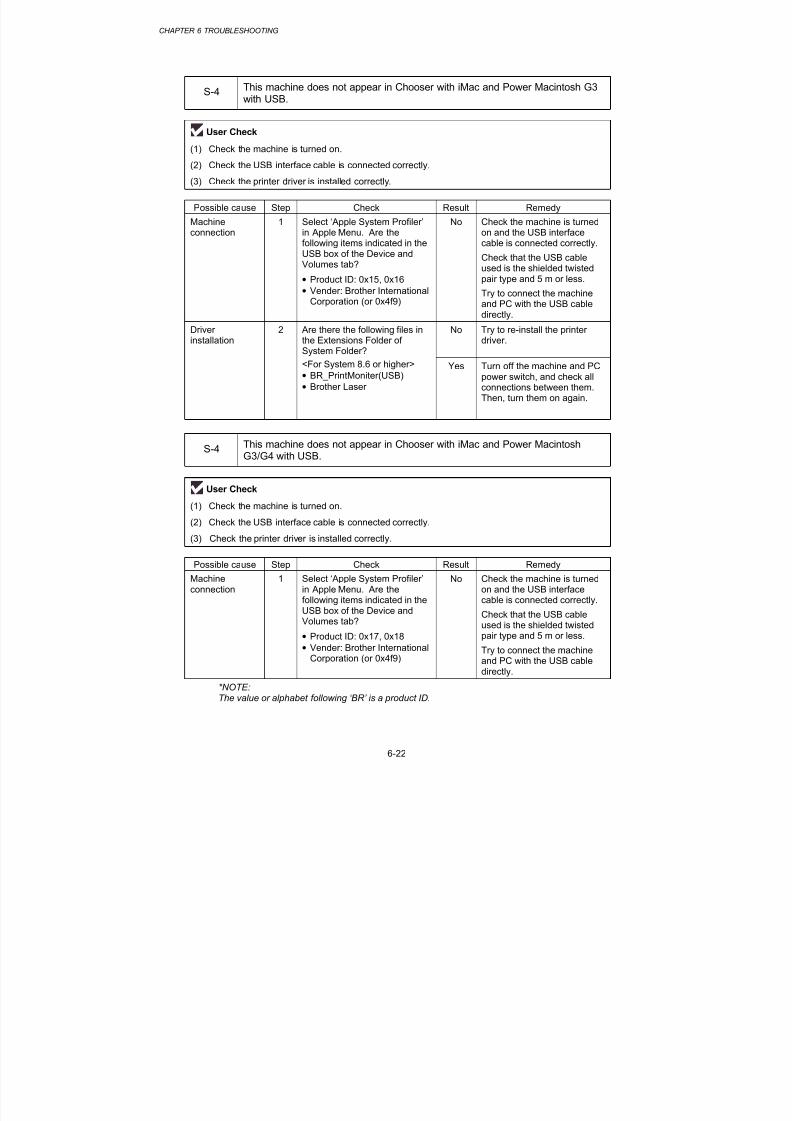
8/9/2019 DCP8040 DCP8045D MFC8440 MFC8840D MFC8840DN Manuales Técnicos.pdf
http://slidepdf.com/reader/full/dcp8040-dcp8045d-mfc8440-mfc8840d-mfc8840dn-manuales-tecnicospdf 225/361
CHAPTER 6 TROUBLESHOOTING
6-22
S-4 This machine does not appear in Chooser with iMac and Power Macintosh G3with USB.
User Check
(1) Check the machine is turned on.
(2) Check the USB interface cable is connected correctly.
(3) Check the printer driver is installed correctly.
Possible cause Step Check Result Remedy
Machineconnection
1 Select ‘Apple System Profiler’in Apple Menu. Are thefollowing items indicated in theUSB box of the Device andVolumes tab?
• Product ID: 0x15, 0x16• Vender: Brother International
Corporation (or 0x4f9)
No Check the machine is turnedon and the USB interfacecable is connected correctly.
Check that the USB cableused is the shielded twisted
pair type and 5 m or less.
Try to connect the machineand PC with the USB cabledirectly.
Driverinstallation
2 Are there the following files inthe Extensions Folder ofSystem Folder?
No Try to re-install the printerdriver.
<For System 8.6 or higher>
• BR_PrintMoniter(USB)
• Brother Laser
Yes Turn off the machine and PCpower switch, and check allconnections between them.Then, turn them on again.
S-4 This machine does not appear in Chooser with iMac and Power MacintoshG3/G4 with USB.
User Check
(1) Check the machine is turned on.
(2) Check the USB interface cable is connected correctly.
(3) Check the printer driver is installed correctly.
Possible cause Step Check Result Remedy
Machineconnection
1 Select ‘Apple System Profiler’in Apple Menu. Are thefollowing items indicated in theUSB box of the Device andVolumes tab?
• Product ID: 0x17, 0x18
• Vender: Brother InternationalCorporation (or 0x4f9)
No Check the machine is turnedon and the USB interfacecable is connected correctly.
Check that the USB cableused is the shielded twistedpair type and 5 m or less.
Try to connect the machineand PC with the USB cabledirectly.
*NOTE:The value or alphabet following ‘BR’ is a product ID.

8/9/2019 DCP8040 DCP8045D MFC8440 MFC8840D MFC8840DN Manuales Técnicos.pdf
http://slidepdf.com/reader/full/dcp8040-dcp8045d-mfc8440-mfc8840d-mfc8840dn-manuales-tecnicospdf 226/361
MFC-8440/8840D/8840DN, DCP-8040/8045D/8045DNSERVICE MANUAL
6-23
5. MALFUNCTIONS
When taking countermeasures for malfunctions as described in this section, check connectorsfor contact failure before measuring the voltage at the specified connector pins.
M-1 No AC power supplied
Possible cause Step Check Result Remedy
Supply voltage 1 Is the correct voltage presentat the outlet?
No Inform the user that thecorrect voltage is not suppliedat the outlet.
Power plug 2 Is the power cord securelyplugged into the outlet?
No Plug the power cord securelyinto the outlet.
Fuse (F1, F2) 3 Is the fuse blown? Yes If the fuse blows againimmediately after replacingthe low-voltage power supply
PCB, check that there is not ashort circuit somewhere in the
AC power supply line.
Wiring 4 Unplug the power supply plug.Is there a broken wire betweenthe AC input connector of thelow-voltage power supply andthe power plug?
Yes Replace the AC power cord.
M-2 No DC power supplied
Possible cause Step Check Result Remedy
AC powersupply
1 Is AC power supplied betweenconnectors CN1-L and CN1-Nwhen the power plug isplugged into the outlet?
No Follow the same checkprocedure of M-1 “No ACpower supplied”.
Wiring, DC load 2 Turn on the power switch.Measure the voltages betweenthe terminals. Do themeasured voltage satisfy theprescribed valued in the tablebelow?
Yes Turn off the power switch,reconnect the connector andturn the power switch onagain. If the protector circuitis activated, check theconnector, the wiring from theconnector, and the DC load.
Low-voltagepower supplyPCB
3 Refer to the chart *1 below. No Replace the low-voltagepower supply PCB.
*1
PCB +lead pin - lead pin Voltage
Engine CN8-3
CN10-6
CN8-2
CN10-5
Approx. 24V
Approx. 3.3V

8/9/2019 DCP8040 DCP8045D MFC8440 MFC8840D MFC8840DN Manuales Técnicos.pdf
http://slidepdf.com/reader/full/dcp8040-dcp8045d-mfc8440-mfc8840d-mfc8840dn-manuales-tecnicospdf 227/361
CHAPTER 6 TROUBLESHOOTING
6-24
WARNING
I f you analyze malfunct ions w ith the pow er plug inser ted into the po wer out le t , specia l
caut ion shou ld be exerc ised even i f the pow er switch is OFF because i t is a single pole
switch.
M-3 Main motor failure
Possible cause Step Check Result Remedy
Failure ofconnector
1 Is the connection of connectorCN9 on the engine PCBcorrect?
No Reconnect the connector.
Main motor 2 Is the problem solved byreplacing the main motor?
Yes Replace the main motor.
Engine PCB 3 Is the problem solved byreplacing the engine PCB?
Yes Replace the engine PCB.
Main PCB 4 Is the problem solved byreplacing the main PCB?
Yes Replace the main PCB.
M-4 No paper supplied
Possible cause Step Check Result Remedy
Failure of
connector
1 Is the contact of the solenoid
connector on the engine PCBgood?
No Reconnect the connector.
Engine PCBcircuit
2 Set paper in the manual paperslot and make a test print bypressing the control panelbutton.
Yes Replace the engine PCB.
Paper pick-upclutch solenoid
Does the voltage between pins2 (SOLENOID) and 1 (24V) ofthe CN16 connector on theengine PCB change fromapprox. 24V DC to 0V withinthe specified time?
No Replace the paper pick-upsolenoid.
Separation pad /pick-up rollerfailure
3 Is the surface of the separationpad or the pick-up roller dirty orworn out?
Yes 1) Clean the surface of theseparation pad or pick-uproller.
2) Replace the separationpad or pick-up roller.
Main PCB 4 Is the problem solved byreplacing the main PCB?
Yes Replace the main PCB.
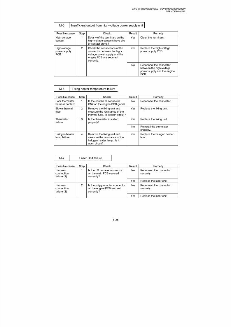
8/9/2019 DCP8040 DCP8045D MFC8440 MFC8840D MFC8840DN Manuales Técnicos.pdf
http://slidepdf.com/reader/full/dcp8040-dcp8045d-mfc8440-mfc8840d-mfc8840dn-manuales-tecnicospdf 228/361
MFC-8440/8840D/8840DN, DCP-8040/8045D/8045DNSERVICE MANUAL
6-25
M-5 Insufficient output from high-voltage power supply unit
Possible cause Step Check Result Remedy
High-voltage
contact
1 Do any of the terminals on the
high-voltage contacts have dirtor contact burns?
Yes Clean the terminals.
High-voltagepower supplyPCB
2 Check the connections of theconnector between the high-voltage power supply and theengine PCB are securedcorrectly.
Yes Replace the high-voltagepower supply PCB
No Reconnect the connectorbetween the high-voltagepower supply and the enginePCB.
M-6 Fixing heater temperature failure
Possible cause Step Check Result Remedy
Poor thermistorharness contact
1 Is the contact of connectorCN7 on the engine PCB good?
No Reconnect the connector.
Blown thermalfuse
2 Remove the fixing unit andmeasure the resistance of thethermal fuse. Is it open circuit?
Yes Replace the fixing unit.
Thermistorfailure
3 Is the thermistor installedproperly?
Yes Replace the fixing unit.
No Reinstall the thermistorproperly.
Halogen heaterlamp failure
4 Remove the fixing unit andmeasure the resistance of thehalogen heater lamp. Is itopen circuit?
Yes Replace the halogen heaterlamp.
M-7 Laser Unit failure
Possible cause Step Check Result Remedy
Harnessconnectionfailure (1)
1 Is the LD harness connectoron the main PCB securedcorrectly?
No Reconnect the connectorsecurely.
Yes Replace the laser unit.
Harnessconnectionfailure (2)
2 Is the polygon motor connectoron the engine PCB securedcorrectly?
No Reconnect the connectorsecurely.
Yes Replace the laser unit.

8/9/2019 DCP8040 DCP8045D MFC8440 MFC8840D MFC8840DN Manuales Técnicos.pdf
http://slidepdf.com/reader/full/dcp8040-dcp8045d-mfc8440-mfc8840d-mfc8840dn-manuales-tecnicospdf 229/361
CHAPTER 6 TROUBLESHOOTING
6-26
M-9 Fixing Unit failure
Possible cause Step Check Result Remedy
Poor thermistor
harness contact
1 Is the contact of connector
CN7 on the engine PCB good?
No Reconnect the connector.
Blown thermalfuse
2 Remove the fixing unit andmeasure the resistancebetween the input connectors.Is it open circuit?
Yes Replace the fixing unit.
Thermistorfailure
3 Is the thermistor installedproperly?
Yes Replace the fixing unit.
No Reinstall the thermistorproperly.
Halogen heaterlamp failure
4 Remove the fixing unit andmeasure the resistance of the
halogen heater lamp. Is itopen circuit?
Yes Replace the halogen heaterlamp.
Heater harnessconnectionfailure
5 Is the heater harnessconnector connected to thelow-voltage power supply PCBand fixing unit secure?
No Reconnect the connectorssecurely.
NOTE:
• This problem will be cleared if leaving the printer power ON for ten minutes.
• If the heater is cooled down sufficiently, this problem may be cleared by enter the
maintenance mode after press 9 key twice. Be w arned, however , that th is operat ion
wi l l melt the f ix ing u ni t i f the heater is hot .
M-10 Main PCB failure
Possible cause Step Check Result Remedy
Main PCB 1 Is it possible to copy? No Replace the main PCB.
Software bug 2 Does this problem appearwhen printing specific data orprinting under a specificenvironment?
Yes Inform the Brother office ofthe used specific data,machine condition andsystem environment.

8/9/2019 DCP8040 DCP8045D MFC8440 MFC8840D MFC8840DN Manuales Técnicos.pdf
http://slidepdf.com/reader/full/dcp8040-dcp8045d-mfc8440-mfc8840d-mfc8840dn-manuales-tecnicospdf 230/361
MFC-8440/8840D/8840DN, DCP-8040/8045D/8045DNSERVICE MANUAL
6-27
M-12 Engine PCB error
Possible cause Step Check Result Remedy
Fixing unit
ground wireconnection
1 Is the ground wire on the fixing
unit secured with the shoulderscrew correctly?
No Secure the ground wire
correctly with the shoulderscrew.
Harnessconnectionfailure
2 Is the connection of theconnector between the mainPCB and the engine PCBconnected correctly?
No Reconnect the connectorssecurely.
Engine PCB 3 Is the problem solved byreplacing the engine PCB?
Yes Replace the engine PCB.
Main PCB 4 Is the problem solved byreplacing the main PCB?
Yes Replace the main PCB.
M-14 DIMM failure
Possible cause Step Check Result Remedy
DIMM failure 1 Try installing DIMM intoanother machine, then checkthe memory size in PrintSettings.
Yes Replace the main PCB.
Is it possible to print the data? No Replace the DIMM.

8/9/2019 DCP8040 DCP8045D MFC8440 MFC8840D MFC8840DN Manuales Técnicos.pdf
http://slidepdf.com/reader/full/dcp8040-dcp8045d-mfc8440-mfc8840d-mfc8840dn-manuales-tecnicospdf 231/361
CHAPTER 6 TROUBLESHOOTING
6-28
6. TROUBLESHOOTING OF THE CONTROL PANEL
L-1 Nothing is displayed on the LCD.
User Check
(1) Verify if the power switch is turned off.
Possible cause Step Check Result Remedy
Connectionbetween mainPCB, relay PCB,and controlpanel PCB
1 Main PCB and control panel
PCB are properly connected.
No Fix the connector properly.
Harness
between mainPCB, relay PCB,and controlpanel PCB
2 Harness wire is damaged. Yes Replace the harness with a
normal part.
Connectionbetween mainPCB and low-voltage powersupply PCB
3 Main PCB and low-voltage
power supply PCB are
properly connected.
No Fix the connection properly.
Harnessbetween mainPCB and low-
voltage powersupply PCB LCD
4 Harness wire is damaged. Yes Replace the harness with a
normal part.
LCD 5 Replacement of LCD solves
the problem.
Yes Replace the LCD with a
normal part.
Control panelPCB
6 Replacement of control panel
PCB solves the problem.
Yes Replace the control panel
PCB with a normal part.
Relay PCB 7 Replacement of relay PCB
solves the problem.
Yes Replace the relay PCB with a
normal part.
Low-voltagepower supplyPCB
8 Replacement of low-voltage
power supply PCB solves the
problem.
Yes Replace the low-voltage
power supply PCB with a
normal part.
Main PCB 9 Replacement of main PCB
solves the problem.
Yes Replace the main PCB with
a normal part.

8/9/2019 DCP8040 DCP8045D MFC8440 MFC8840D MFC8840DN Manuales Técnicos.pdf
http://slidepdf.com/reader/full/dcp8040-dcp8045d-mfc8440-mfc8840d-mfc8840dn-manuales-tecnicospdf 232/361
MFC-8440/8840D/8840DN, DCP-8040/8045D/8045DNSERVICE MANUAL
6-29
L-2 The control panel does not work.
User Check
(1) No
Possible cause Step Check Result Remedy
Key sticking 1 Any key on control panel is
stuck.
Yes Clean up the panel cover, or
remove the burrs from panel
cover and panel keys.
Connectionbetween mainPCB, relay PCB,and controlpanel PCB
2 Main PCB, relay PCB, and
control panel PCB are
properly connected.
No Fix the connection properly.
Harnessbetween mainPCB, relay PCB,and controlpanel PCB
3 Harness wire is damaged. Yes Replace the harness with a
normal part.
Connection ofFPC key
4 FPC key is properly
connected.
No Fix the connection properly.
FPC key 5 Replacement of FPC key
solves the problem.
Yes Replace the FPC key with a
normal part.
Relay PCB 6 Replacement of relay PCB
solves the problem.
Yes Replace the relay PCB with a
normal part.
Control panel
PCB
7 Replacement of control panel
PCB solves the problem.
Yes Replace the control panel
PCB with a normal part.
Main PCB 8 Replacement of main PCB
solves the problem.
Yes Replace the main PCB with
a normal part.
L-3 Printing from Macintosh applications fails.
User Check
(1) Verify that the printer driver supplied with the printer has been installed in the system folder andselected in the selector.
(2) Check the port selected in the selector. The selected port has to match the actual port to whichthe printer cable is connected.
Possible cause Step Check Result Remedy
Fault in printer 1 Test page can be printed
using the method described in
3.5 ‘Test Pattern 1’ in Chapter
7.
No Check the symptom of the
problem and refer to an
appropriate section in this
Chapter to solve the
problem.
Breakage ofmain PCB
2 Printing can be made using
an appropriate PC, printer
cable, and RS-100M ?
No Replace the main PCB.

8/9/2019 DCP8040 DCP8045D MFC8440 MFC8840D MFC8840DN Manuales Técnicos.pdf
http://slidepdf.com/reader/full/dcp8040-dcp8045d-mfc8440-mfc8840d-mfc8840dn-manuales-tecnicospdf 233/361

8/9/2019 DCP8040 DCP8045D MFC8440 MFC8840D MFC8840DN Manuales Técnicos.pdf
http://slidepdf.com/reader/full/dcp8040-dcp8045d-mfc8440-mfc8840d-mfc8840dn-manuales-tecnicospdf 234/361
MFC-8440/8840D/8840DN, DCP-8040/8045D/8045DNSERVICE MANUAL
6-31
F-2 Speed dialing and One-touch dialing can't be used.
Possible cause Step Check Result Remedy
Speed dialing,
One-touchdialing
1 A fax transmission can be
made using the key, ten?
Yes Replace the main PCB.
Dialing modesetting
2 Dialing signal (PB or DP)
comes out normally in each
mode.
(Use telephone line emulator.)
Yes Check the dialing mode
setting at customer's again.
Check the telephone line
cord between machine and
socket.
Connectionbetween mainPCB and NCUPCB
3 Main PCB and NCU PCB are
properly connected.
No Fix the connection properly.
Harnessbetween mainPCB and NCUPCB
4 Harness wire is damaged. Yes Replace the harness with a
normal part.
Connectionbetween mainPCB and controlpanel PCB
5 Main PCB and control panel
PCB are properly connected.
No Fix the connection properly.
Harnessbetween mainPCB and controlpanel PCB
6 Harness wire is damaged. Yes Replace the harness with a
normal part.
Connection ofFPC key 7FPC key is properly
connected.
No Fix the connection properly.
FPC key 8 Replacement of FPC key
solves the problem.
Yes Replace the FPC key with a
normal part.
NCU PCB 9 Replacement of NCU PCB
solves the problem.
Yes Replace the NCU PCB with
a normal part.
Control panelPCB
10 Replacement of control panel
PCB solves the problem.
Yes Replace the control panel
PCB with a normal part.
F-3 FAX can't be received.
User Check (1) Verify that the telephone cord is securely inserted.
Possible cause Step Check Result Remedy
Receive modesetting
1 Receive mode is set to
automatic receive mode.
No Set the receive mode to
automatic receive mode.
NCU PCB 2 Replacement of NCU PCB
solves the problem.
Yes Replace the NCU PCB with
a normal part.
Main PCB 3 Replacement of main PCB
solves the problem.
Yes Replace the main PCB with
a normal part.

8/9/2019 DCP8040 DCP8045D MFC8440 MFC8840D MFC8840DN Manuales Técnicos.pdf
http://slidepdf.com/reader/full/dcp8040-dcp8045d-mfc8440-mfc8840d-mfc8840dn-manuales-tecnicospdf 235/361
CHAPTER 6 TROUBLESHOOTING
6-32
F-4 No bell ring.
Possible cause Step Check Result Remedy
Ring delay 1 Ring delay is set to "0". Yes Set the ring delay to other
than "0".
Ring volume 2 Ring volume is set to "OFF". Yes Set the ring volume to other
than "OFF".
Connectionbetween mainPCB and NCUPCB
3 Main PCB and NCU PCB are
properly connected.
No Fix the connection properly.
Harnessbetween mainPCB and NCUPCB
4 Harness wire is damaged. Yes Replace the harness with a
normal part.
Speaker 5 Replacement of speaker
solves the problem.
Yes Replace the speaker with a
normal part.
Relay PCB 6 Replacement of relay PCB
solves the problem.
Yes Replace the relay PCB with a
normal part.
NCU PCB 7 Replacement of NCU PCB
solves the problem.
Yes Replace the NCU PCB with
a normal part.
Main PCB 8 Replacement of main PCB
solves the problem.
Yes Replace the main PCB with
a normal part.

8/9/2019 DCP8040 DCP8045D MFC8440 MFC8840D MFC8840DN Manuales Técnicos.pdf
http://slidepdf.com/reader/full/dcp8040-dcp8045d-mfc8440-mfc8840d-mfc8840dn-manuales-tecnicospdf 236/361
MFC-8440/8840D/8840DN, DCP-8040/8045D/8045DNSERVICE MANUAL
6-33
F-5Speaker is silent during on-hook dialing.
Possible cause Step Check Result Remedy
Connectionbetween mainPCB andspeaker
1 Main PCB and speaker areproperly connected.
No Fix the connection properly.
Speaker 2 Replacement of speaker
solves the problem.
Yes Replace the speaker with a
normal part.
Connectionbetween mainPCB and NCUPCB
3 Main PCB and NCU PCB are
properly connected.
No Fix the connection properly.
Harnessbetween main
PCB and NCUPCB
4 Harness wire is damaged. Yes Replace the harness with a
normal part.
Connectionbetween mainPCB, relay PCB,and controlpanel PCB
5 Main PCB, relay PCB, and
control panel PCB are
properly connected.
No Fix the connection properly.
Harnessbetween mainPCB, relay PCB,and controlpanel PCB
6 Harness wire is damaged. Yes Replace the harness with a
normal part.
NCU PCB 7 Replacement of NCU PCBsolves the problem.
Yes Replace the NCU PCB witha normal part.
Relay PCB 8 Replacement of relay PCB
solves the problem.
Yes Replace the relay PCB with a
normal part.
Main PCB 9 Replacement of main PCB
solves the problem.
Yes Replace the main PCB with
a normal part.
F-6Dialing function does not switch between "tone" and "pulse".
Possible cause Step Check Result Remedy
Connectionbetween mainPCB and NCUPCB
1 Main PCB and NCU PCB areproperly connected.
No Fix the connection properly.
Harnessbetween mainPCB and NCUPCB
2 Harness wire is damaged. Yes Replace the harness with a
normal part.
NCU PCB 3 Replacement of NCU PCB
solves the problem.
Yes Replace the NCU PCB with
a normal part.
Main PCB 4 Replacement of main PCB
solves the problem.
Yes Replace the main PCB with
a normal part.

8/9/2019 DCP8040 DCP8045D MFC8440 MFC8840D MFC8840DN Manuales Técnicos.pdf
http://slidepdf.com/reader/full/dcp8040-dcp8045d-mfc8440-mfc8840d-mfc8840dn-manuales-tecnicospdf 237/361
CHAPTER 6 TROUBLESHOOTING
6-34
8. IMAGE DEFECTS
8.1 Image Defect Examples
I-2 DarkI-1 Light I-2 Dark I-3 Completely blank I-4 All black I-5 Dirt on back of paper
I-6 Black vertical streaks
I-6 Black verticalstreaks
I-7 Black horizontalstripes
I-12 Poor fixing I-13 Image distortion I-14 Faint print
Print out test print out test print out test Print out test print or int out test pr int out test pr int out test r int out test pr int o Print out test print o
Print out test print out test print out test Print out test print or int out test pr int out test pr int out test r int out test pr int o Print out test print o
Print out test print out test print out test Print out test print or int out test pr int out test pr int out test r int out test pr int o Print out test print o
Print out test print out test print out test Print out test print or int out test pr int out test pr int out test r int out test pr int o Print out test print o
Print out test print out test print out test Print out test print or int out test pr int out test pr int out test r int out test pr int o Print out test print o
Print out test print out test print out test Print out test print or int out test pr int out test pr int out test r int out test pr int o Print out test print o
Print out test print out test print out test Print out test print or int out test pr int out test pr int out test r int out test pr int o Print out test print o
Print out test print out test print out test Print out test print or int out test pr int out test pr int out test r int out test pr int o Print out test print o
Print out test print out test print out test Print out test print or int out test pr int out test pr int out test r int out test pr int o Print out test print o
Print out test print out test print out test Print out test print or int out test pr int out test pr int out test r int out test pr int o Print out test print o
Print out test print out test print out test Print out test print or int out test pr int out test pr int out test r int out test pr int o Print out test print o
Print out test print out test print out test Print out test print or int out test pr int out test pr int out test r int out test pr int o Print out test print o
Print out test print out test print out test Print out test print or int out test pr int out test pr int out test r int out test pr int o Print out test print o
P r i n t o u t t e s t p r i n t o u t t e s t p r i n t o u t t e s t P r i n t o u t t e s t p r i n t o P r i n t o u t t e s t p r i n t o
P r i n t o u t t e s t p r i n t o u t t e s t p r i n t o u t t e s t P r i n t o u t t e s t p r i n t o P r i n t o u t t e s t p r i n t o
P r i n t o u t t e s t p r i n t o u t t e s t p r i n t o u t t e s t P r i n t o u t t e s t p r i n t o P r i n t o u t t e s t p r i n t o
P r i n t o u t t e s t p r i n t o u t t e s t p r i n t o u t t e s t P r i n t o u t t e s t p r i n t o P r i n t o u t t e s t p r i n t o
P r i n t o u t t e s t p r i n t o u t t e s t p r i n t o u t t e s t P r i n t o u t t e s t p r i n t o P r i n t o u t t e s t p r i n t o
P r i n t o u t t e s t p r i n t o u t t e s t p r i n t o u t t e s t P r i n t o u t t e s t p r i n t o P r i n t o u t t e s t p r i n t o
P r i n t o u t t e s t p r i n t o u t t e s t p r i n t o u t t e s t P r i n t o u t t e s t p r i n t o P r i n t o u t t e s t p r i n t o
P r i n t o u t t e s t p r i n t o u t t e s t p r i n t o u t t e s t P r i n t o u t t e s t p r i n t o P r i n t o u t t e s t p r i n t o
P r i n t o u t t e s t p r i n t o u t t e s t p r i n t o u t t e s t P r i n t o u t t e s t p r i n t o P r i n t o u t t e s t p r i n t o
P r i n t o u t t e s t p r i n t o u t t e s t p r i n t o u t t e s t P r i n t o u t t e s t p r i n t o P r i n t o u t t e s t p r i n t o
P r i n t o u t t e s t p r i n t o u t t e s t p r i n t o u t t e s t P r i n t o u t t e s t p r i n t o P r i n t o u t t e s t p r i n t o
P r i n t o u t t e s t p r i n t o u t t e s t p r i n t o u t t e s t P r i n t o u t t e s t p r i n t o P r i n t o u t t e s t p r i n t o
P r i n t o u t t e s t p r i n t o u t t e s t p r i n t o u t t e s t P r i n t o u t t e s t p r i n t o P r i n t o u t t e s t p r i n t o
I-19 Hollow printI-15 White spots I-16 Black spots I-18 Gray backgroundI-17 Black band
I-20 Downward foggingof solid black
I-21 Horizontal lines
I-11 Faultyregistration
I-10 White horizontalstreaks
I-8 Black verticalstreaks
I-9 White verticalstreaks
I-23 GhostI-22 Light rain I-24 Toner specks
Fig. 6-14
8.2 Diameter of Rollers
The diameter of each roller and the pitch which appears in the image are listed below;
No. Parts Name Diameter (The pitch whichappears in the image)
1 First Paper Feed Roller φ 13.6 mm (42.7 mm)
2 Paper Feed Roller φ 14.0 mm (44.0 mm)
3 Transfer Roller φ 15.20 mm (47.7 mm)
4 Photosensitive Drum φ 29.97 mm (94.1 mm)
5 Heat Roller φ 25.0 mm (78.5 mm)
6 Pressure Roller φ 25.0 mm (78.5 mm)
7 Development Roller φ 20.0 mm (39.0 mm)

8/9/2019 DCP8040 DCP8045D MFC8440 MFC8840D MFC8840DN Manuales Técnicos.pdf
http://slidepdf.com/reader/full/dcp8040-dcp8045d-mfc8440-mfc8840d-mfc8840dn-manuales-tecnicospdf 238/361
MFC-8440/8840D/8840DN, DCP-8040/8045D/8045DNSERVICE MANUAL
6-35
8.3 Troubleshooting Image Defect
Several types of the image defects can be cleared by end users. For those defects, instructthe user to check the ‘User Check’ items described in each table. Even if the same imagedefect appears, the following procedures should be followed in the event of specific imagedefects.
See also subsection 8.4 ‘Location of Ground Contacts’ in this Chapter f or information about thelocation of the grounding contacts.
! CAUTION:
When using the machine for a special job, such as printing of name cards, print quality cannotbe guaranteed.
I-1 Light
Possible cause Step Check Result RemedyGroundcontacts
Toner sensingfailure
(machine side)
1 Can printing be started with thedrum unit and toner cartridge
removed?
Yes Check if the tonersensor is dirty and
check the tonersensor connection.
Toner sensingfailure(toner cartridgeside)
2 Is the problem solved when 4or 5 pages are printed after thetoner cartridge is replaced witha full one?
Yes The wiper of the tonercartridge is defective.Replace the tonercartridge.
Drumconnectionfailure
3 Are all the contacts betweenthe drum unit and machineconnected correctly?
No Clean contactelectrodes both on thedrum unit and in themachine.
(1), (4),
(5), (6)
High-voltage
power supplyPCB failure
4 Is the harness connection
between the high-voltagepower supply PCB and theengine PCB correct?
Yes Replace the high-
voltage power supplyPCB.
Engine PCB /Main PCBfailure
5 Is the harness connectionbetween the engine PCB andthe main PCB correct?
Yes Replace the enginePCB or the main PCB.
Dirt on thescanner window
6 Is there any dirt on the scannerwindow?
Yes Wipe it off with a softclean paper.
Laser unit failure 7 Is the problem solved afterreplacing the laser unit?
Yes Replace the laser unit.
User Check (1) Check the printer’s environment. Conditions such as humidity, high
temperatures, etc. may cause this situation to occur.
(2) If the whole page is light, toner save mode may be on. Disable toner save modewithin Printer Properties tab of the driver.
(3) Try installing a new toner cartridge or drum unit.

8/9/2019 DCP8040 DCP8045D MFC8440 MFC8840D MFC8840DN Manuales Técnicos.pdf
http://slidepdf.com/reader/full/dcp8040-dcp8045d-mfc8440-mfc8840d-mfc8840dn-manuales-tecnicospdf 239/361
CHAPTER 6 TROUBLESHOOTING
6-36
I-2 Dark
Possible cause Step Check Result RemedyGroundcontacts
Corona failure(contact failure)
1 Are the charge electrodesbetween the machine and thedrum unit dirty?
Yes Clean both electrodes.(3)
Drum unit failure 2 Is the problem solved afterreplacing the drum unit?
Yes Replace the drum unitwith a new one.
Toner cartridgefailure
3 Is the problem solved afterreplacing the toner cartridge?
Yes Replace the tonercartridge with a newone.
High-voltagepower supplyPCB failure
4 Is the connections of theconnector between the high-voltage power supply PCB andthe engine PCB securedcorrectly?
Yes Replace the high-voltage power supplyPCB.
Main PCBfailure
5 Are there any disconnectedconnectors?
No Replace the mainPCB.
Engine PCBfailure
6 Are there any disconnectedconnectors?
No Replace the enginePCB.
User Check
(1) Check the paper used meets the recommended paper specifications.
(2) Check the machine’s environment. High temperature and high humidityconditions can increase the amount of background shading.
(3) Clean the corona wire with the wire cleaner.
(4) Try installing a new toner cartridge or drum unit.

8/9/2019 DCP8040 DCP8045D MFC8440 MFC8840D MFC8840DN Manuales Técnicos.pdf
http://slidepdf.com/reader/full/dcp8040-dcp8045d-mfc8440-mfc8840d-mfc8840dn-manuales-tecnicospdf 240/361
MFC-8440/8840D/8840DN, DCP-8040/8045D/8045DNSERVICE MANUAL
6-37
I-3 Completely blank
Possible cause Step Check Result RemedyGroundcontacts
Developing biascontact failure
1 Are the developing biascontacts between the machinebody and drum unit dirty?
Yes Clean the electrodesat both sides. (4)
Drum unit 2 Are the drum shaft and drumelectrode of the machine
connected correctly?
Yes Clean the shaft andthe electrode. (1)
No Check the connectionbetween the shaft andthe electrode.
(1)
Drum unit failure 3 Is the problem solved afterreplacing the drum unit?
Yes Replace the drumunit.
Toner cartridgefailure
4 Is the problem solved afterreplacing the toner cartridge?
Yes Replace the tonercartridge with a newone.
Scannerharness
connectionfailure
5 Is the scanner harnessconnected securely?
(Check if there is any play inthe connection.)
No Reconnect theconnector correctly.
Main PCBfailure
6 Are printing signals being inputto the laser unit?
Is the problem solved afterreplacing the main PCB?
Yes Replace the mainPCB.
Laser unit failure 7 Is the scanner interlock leverdamaged?
Yes Replace the laser unit.
Is the scanner mirror broken orloose?
No Replace the high-voltage power supply
PCB.CCD unit 8 Is the problem occurring on
CCD replacement? Yes Replace the CCD.
User Check
(1) Check for the setting of originals.

8/9/2019 DCP8040 DCP8045D MFC8440 MFC8840D MFC8840DN Manuales Técnicos.pdf
http://slidepdf.com/reader/full/dcp8040-dcp8045d-mfc8440-mfc8840d-mfc8840dn-manuales-tecnicospdf 241/361
CHAPTER 6 TROUBLESHOOTING
6-38
I-4 All black
Possible cause Step Check Result RemedyGroundcontacts
Corona failure 1 Is the corona wire dirty? Yes Clean the corona wirewith the wire cleaner.
(2)
2 Is the corona wire broken? Yes Replace the drumunit.
3 Are the charge electrodesbetween the machine and thedrum unit dirty?
Yes Clean both electrodes.(3)
Harnessconnection
4 Is the laser unit connected tothe main PCB correctly?
No Connect the harnessbetween the laser unitand the main PCBcorrectly.
High-voltagepower supplyPCB failure
5 Is the problem solved afterreplacing the high-voltagepower supply PCB?
Yes Replace the high-voltage power supplyPCB.
Main PCBfailure
6 Is the problem solved afterreplacing the main PCB?
Yes Replace the mainPCB.
CCD unit 7 Is the problem occurring onCCD replacement?
Yes Replace the CCD.
User Check
(1) Clean the corona wire of the drum unit.(2) The drum unit may be damaged. Install a new drum unit.

8/9/2019 DCP8040 DCP8045D MFC8440 MFC8840D MFC8840DN Manuales Técnicos.pdf
http://slidepdf.com/reader/full/dcp8040-dcp8045d-mfc8440-mfc8840d-mfc8840dn-manuales-tecnicospdf 242/361
MFC-8440/8840D/8840DN, DCP-8040/8045D/8045DN SERVICE MANUAL
6-39
I-5 Dirt on the back of paper
Possible cause Step Check Result Remedy
Fixing unit dirty 1 Is the pressure roller dirty?
Is any other area in themachine dirty?
Yes Clean the pressure roller referring to the followingprocedure.
Dirt in the drumunit
2 Is the transfer roller dirty?
Is the problem solved after
replacing the drum unit?
Yes Replace the drum unit
No Replace the high-voltage power supply PCB.
NOTE:
This problem may disappear after printing approximately 10 pages of completely blank sheets.
How to clean the pressure roller
Clean the pressure roller as follows
(1) Set ten or more sheets of paper in the paper tray.
(2) Check the absence of paper in the ADF and on the scanner glass.
(3) Press Copy button to copy and repeat it five times.
(4) Check whether any stain are observed on the back of paper or not.

8/9/2019 DCP8040 DCP8045D MFC8440 MFC8840D MFC8840DN Manuales Técnicos.pdf
http://slidepdf.com/reader/full/dcp8040-dcp8045d-mfc8440-mfc8840d-mfc8840dn-manuales-tecnicospdf 243/361
CHAPTER 6 TROUBLESHOOTING
6-40
I-6 Black and blurred vertical streaks
Possible cause Step Check Result Remedy
Dirt on the
scanner glass.
1 Is there any dirt on that? Yes Clean the scanner glass.
Dirt on the CCD. 2 Is there any dirt on that? Yes Replace the CCD.
Corona failure 3 Is the vertical block streakabout 10mm wide?(Check if the wire cleaner is atits home position.)
Yes Return the wire cleaner to itshome position.
Dirt in the paperfeed system
4 Is the paper tray or feedsystem on the drum unit dirtywith toner?
Yes Clean the toner off.
Scratch on thedrum
5 Is the drum surface scratched? Yes Replace the drum unit.
Cleaning failure 6 Is the drum surface dirty withtoner in streaks?
Yes Replace the drum unit.
Scratch on theheat roller
7 Is the surface of the heat rollerscratched?
Yes Replace the fixing unit.
NOTE:
• If you print the same pattern continuously, the drum will be worn and black vertical streakswill appear on the paper.
• This problem may occur with noise due to the corona wire being dirty. In that case, cleanthe corona wire with the wire cleaner.
User Check
(1) Clean the corona wire in the drum unit.
(2) Check that the corona wire cleaner is at the home position.
(3) Check that the toner cartridge is not empty.
(4) The drum unit may be damaged. Install a new drum unit.
(5) The toner cartridge may be damaged. Install a new toner cartridge.

8/9/2019 DCP8040 DCP8045D MFC8440 MFC8840D MFC8840DN Manuales Técnicos.pdf
http://slidepdf.com/reader/full/dcp8040-dcp8045d-mfc8440-mfc8840d-mfc8840dn-manuales-tecnicospdf 244/361
MFC-8440/8840D/8840DN, DCP-8040/8045D/8045DNSERVICE MANUAL
6-41
I-7 Black and blurred horizontal stripes
Possible cause Step Check Result Remedy Groundcontacts
Scratch on thedrum
1 Are the horizontal stripes at94mm (photosensitive drum)intervals?
Yes The photosensitivedrum was scratched.Replace the drumunit.
Toner stuck onthe developerroller
2 Are the horizontal stripes at39mm (developer roller)intervals?
Yes After printing severalpages, the problemwill disappear.If not, replace thetoner cartridge.
Scratch on theheat roller
3 Are the horizontal stripes at79mm (heat roller) intervals?
Yes Replace the heatroller.
Corona contactfailure
4 Are the charge electrodesbetween the machine and thedrum unit dirty?
Yes Clean both electrodes.
(3)
High-voltage
power supplyPCB failure
5 Is the problem solved after
replacing the high-voltagepower supply PCB?
Yes Replace the high-
voltage power supplyPCB.
I-8 Black vertical streaks (in a gray background)
Possible cause Step Check Result RemedyGroundcontacts
Translucentstain on thescanner window
1 Is there any dirt on the scannerwindow?
Yes 1) Clean the scannerwindow.
2) If it is not effective,replace the laserunit.
Corona failure 2 Is the corona wire dirty? Yes Clean the corona wirewith the wire cleaner.
(2)
User Check
(1) The drum unit may be damaged. Install a new drum unit.
(2) Check the paper used meets the recommended paper specifications.
(3) Clean the machine interior and the corona wire in the drum unit.

8/9/2019 DCP8040 DCP8045D MFC8440 MFC8840D MFC8840DN Manuales Técnicos.pdf
http://slidepdf.com/reader/full/dcp8040-dcp8045d-mfc8440-mfc8840d-mfc8840dn-manuales-tecnicospdf 245/361
CHAPTER 6 TROUBLESHOOTING
6-42
I-9 White vertical streaks
Possible cause Step Check Result Remedy
Dirt on the CCD. 1 Is there any dirt on that? Yes Replace the CCD.
Transfer failure 2 Is the transfer roller scratched? Yes Replace the drum unit.
Condensation 3 Has condensation occurredinside the machine?
Yes Try to print several pages orleave the machine 2 hours toallow it to reach roomtemperature.
I-10 White horizontal stripes
Possible cause Step Check Result RemedyGroundcontacts
Developing biascontact failure
1 Are the developing biascontacts between the machineand toner cartridge dirty?
Yes Clean the electrodesat both sides. (4)
User Check
(1) Try to wipe the scanner window with a soft cloth.
(2) The toner cartridge may be damaged. Install a new toner cartridge.
(3) Check the machine’s environment. High temperature and high humidityconditions can cause this problem.
(4) Damp (wet) paper might be used. Try to change to freshly unpacked paper.
User Check (1) Check the paper used meets the recommended paper specifications. A rough
surfaced paper, damp paper or thick media can cause the problem.
(2) Check that the appropriate media type is selected in the printer driver.
(3) The problem may disappear by itself. Try printing multiple pages to clear thisproblem especially if the machine has not been used for a long time.
(4) The drum unit may be damaged. Install a new drum unit.

8/9/2019 DCP8040 DCP8045D MFC8440 MFC8840D MFC8840DN Manuales Técnicos.pdf
http://slidepdf.com/reader/full/dcp8040-dcp8045d-mfc8440-mfc8840d-mfc8840dn-manuales-tecnicospdf 246/361
MFC-8440/8840D/8840DN, DCP-8040/8045D/8045DNSERVICE MANUAL
6-43
I-11 Faulty registration
Possible cause Step Check Result Remedy
Excessive paperload
1 Is the paper loaded in thepaper tray more than 27mmhigh?
Yes Instruct the user to keep paperloads below 27mm in depth.
Print paper 2 Is the specified weight of therecommended paper being
used?
No Recommend to use thespecified types of paper.
3 Is the first printing positionwithin ±1mm of the tolerancespecification?
Yes Adjust the Y offset by using theutility software supplied.
Rear registsensor positionincorrect
4 Is the position of the rearregistration sensor normal?
No Reposition the sensor to thecorrect position.
I-12 Poor fixing
Possible cause Step Check Result Remedy
Print paper 1 Is thick paper of more than43lb being used?
Yes Recommend to use thespecified types of paper.
Toner sensing
failure(When printingis faint.)
2 Is the problem solved by
replacing the drum unit or thetoner cartridge?
Yes 1) Toner is empty.
2) The toner sensing isdefective. Clean the tonersensor.
3) If the wiper in the tonercartridge is broken, replacethe toner cartridge with a newone.
Fixing unitthermistor failure
3 Is the thermistor fittedcorrectly?
No Fit the thermistor correctly.
Low-voltagepower supplyPCB failure
4 Is the problem solved byreplacing the low-voltagepower supply PCB?
Yes Replace the low-voltage powersupply PCB.

8/9/2019 DCP8040 DCP8045D MFC8440 MFC8840D MFC8840DN Manuales Técnicos.pdf
http://slidepdf.com/reader/full/dcp8040-dcp8045d-mfc8440-mfc8840d-mfc8840dn-manuales-tecnicospdf 247/361
CHAPTER 6 TROUBLESHOOTING
6-44
I-13 Image distortion
Possible cause Step Check Result Remedy
Laser unitinstallation
1 Is the laser unit secured to theframe incorrectly?(Check if there is any play.)
Yes Secure the unit correctly andtighten the screws.
Laser scannerLD emissionfailure
Laser scannermotor rotationfailure
2 Is the laser diode or thescanner motor defective?
Yes Replace the laser unit.
Laser scannerconnectionfailure
3 Is the scanner harnessconnected properly?(Check if it is coming loose.)
No Connect the harness correctly.
I-14 Faint print
rint out test print out test print out test rint out test print o
Print out test print o
rint out test print out test print out test rint out test print o Print out test print o
rint out test print out test print out test rint out test print o
Print out test print o
rint out test print out test print out test rint out test print o Print out test print o
rint out test print out test print out test rint out test print o
Print out test print o
rint out test print out test print out test rint out test print o Print out test print o
rint out test print out test print out test rint out test print o
Print out test print o
rint out test print out test print out test rint out test print o Print out test print o
rint out test print out test print out test rint out test print o
Print out test print o
rint out test print out test print out test rint out test print o Print out test print o
rint out test print out test print out test rint out test print o
Print out test print o
rint out test print out test print out test rint out test print o Print out test print o
rint out test print out test print out test rint out test print o
Print out test print o
P r i n t o u t t e s t p r i n t o
P r i n t o u t t e s t p r i n t o
P r i n t o u t t e s t p r i n t o
P r i n t o u t t e s t p r i n t o
P r i n t o u t t e s t p r i n t o
P r i n t o u t t e s t p r i n t o
P r i n t o u t t e s t p r i n t o
P r i n t o u t t e s t p r i n t o
P r i n t o u t t e s t p r i n t o
P r i n t o u t t e s t p r i n t o
P r i n t o u t t e s t p r i n t o
P r i n t o u t t e s t p r i n t o
P r i n t o u t t e s t p r i n t o
Possible cause Step Check Result Remedy
Machineinstallation
1 Is the machine placedhorizontally?
No Place the machine on a flatsurface.
Toner cartridge 2 Does the problem happenimmediately after replacing thetoner cartridge with a newone?
Yes Remove and carefully shake thetoner cartridge horizontally.
Scanner windowdirty
3 Is the scanner window dirty? Yes Clean the scanner window with asoft dry cloth.
Laser unit failure 4 Is the problem solved byreplacing the laser unit?
Yes Replace the laser unit.

8/9/2019 DCP8040 DCP8045D MFC8440 MFC8840D MFC8840DN Manuales Técnicos.pdf
http://slidepdf.com/reader/full/dcp8040-dcp8045d-mfc8440-mfc8840d-mfc8840dn-manuales-tecnicospdf 248/361
MFC-8440/8840D/8840DN, DCP-8040/8045D/8045DNSERVICE MANUAL
6-45
I-15 White spots
Possible cause Step Check Result Remedy
Drum unit failure 1 Are the white spot at 94mmintervals?
Yes 1) If toner or glue remainsstuck, wipe it off gently with acotton swab. (Refer to NOTE in the next page.)
2) If the drum surface isscratched, replace the drumunit.
Drum unit failure 2 Is the problem solved afterreplacing the drum unit?
Yes Replace the drum unit.
No toner 3 Is the toner in the tonercartridge almost empty?
Yes Replace the toner cartridge witha new one.
Print paper 4 Is the problem solved afterchanging to specified freshlyunpacked paper?
Yes Damp (wet) paper might beused. Recommend to changefreshly unpacked paper.
Environment 5 Does the problem still appear
after the machine has warmedup?
Yes 1) Replace the drum unit.
2) Advise the user of thespecified print environment.
User Check
(1) If the problem is not solved after printing a few pages, the drum unit may haveglue from label stock on the photosensitive drum surface. Refer to Step 1 in thetable below and NOTE in the next page.
(2) The drum unit may be damaged. Install a new drum unit.

8/9/2019 DCP8040 DCP8045D MFC8440 MFC8840D MFC8840DN Manuales Técnicos.pdf
http://slidepdf.com/reader/full/dcp8040-dcp8045d-mfc8440-mfc8840d-mfc8840dn-manuales-tecnicospdf 249/361
CHAPTER 6 TROUBLESHOOTING
6-46
NOTE:
Clean the drum unit as follows:
(1) Remove the toner cartridge from the drum unit. Place the printing samples in front of thedrum unit, and find the exact position of the image defect.
Fig. 6-15
(2) Turn the drum gear by hand while looking at the surface of the photosensitive drum.
Fig. 6-16
(3) Wipe the surface of the photosensitive drum with a cotton swab until the dust or paper powder on the surface comes off.
Fig. 6-17
! CAUTION:
• Do not wipe the surface of the photosensitive drum with something sharp. (ball-point penetc.)
• Use cleaning liquid which is a 50-50 mixture of ethyl alcohol and pure water.
Position of smudge onthe drum
94mm interval
Printing sample
Drum unit
Photosensitive drum
Photosensitive drum

8/9/2019 DCP8040 DCP8045D MFC8440 MFC8840D MFC8840DN Manuales Técnicos.pdf
http://slidepdf.com/reader/full/dcp8040-dcp8045d-mfc8440-mfc8840d-mfc8840dn-manuales-tecnicospdf 250/361
MFC-8440/8840D/8840DN, DCP-8040/8045D/8045DNSERVICE MANUAL
6-47
I-16 Black spots
Possible cause Step Check Result RemedyGroundcontacts
Drum unit 1 Are the spots at 94mmintervals?(The problem is not solvedafter printing a few pages.)
Yes 1) If toner or glueremains stuck, wipe itoff gently with acotton swab. (Refer
to NOTE in theprevious page.)
2) If the photosensitivedrum is scratched ordeteriorated(exposed), replacethe drum unit.
Drumconnectionfailure
2 Is the contact between thedrum unit and machineconnected correctly?
No Clean contact electrodeboth on the drum unitand in the machine.
(8)
Fixing unit 3 Are the spots at 79mmintervals?(The problem is not solvedafter printing a few pages.)
Yes 1) Check and clean theheat roller with a clothdampened withalcohol.
2) Replace the fixingunit.
High-voltagepower supplyPCB failure
4 Is the problem solved afterreplacing the high-voltagepower supply PCB?
Yes Replace the high-voltagepower supply PCB.
User Check
(1) If the problem is not solved after printing a few pages, the drum unit may haveglue from label stock on the photosensitive drum surface. Refer to Step 1 in thetable below and NOTE in the previous page.
(2) The drum unit may be damaged. Install a new drum unit.

8/9/2019 DCP8040 DCP8045D MFC8440 MFC8840D MFC8840DN Manuales Técnicos.pdf
http://slidepdf.com/reader/full/dcp8040-dcp8045d-mfc8440-mfc8840d-mfc8840dn-manuales-tecnicospdf 251/361
CHAPTER 6 TROUBLESHOOTING
6-48
I-17 Black band
Possible cause Step Check Result Remedy Groundcontacts
Corona failure 1 Is the wire cleaner at its homeposition?
No Return the wire cleanerto its home position. (2)
Corona failure 2 Is the corona wire dirty? Yes 1) Clean the coronawire.
2) If the problem still
appears aftercleaning, replacethe drum unit.
(2)

8/9/2019 DCP8040 DCP8045D MFC8440 MFC8840D MFC8840DN Manuales Técnicos.pdf
http://slidepdf.com/reader/full/dcp8040-dcp8045d-mfc8440-mfc8840d-mfc8840dn-manuales-tecnicospdf 252/361
MFC-8440/8840D/8840DN, DCP-8040/8045D/8045DNSERVICE MANUAL
6-49
I-18 Gray background
Possible cause Step Check Result Remedy
Print paper 1 Does the paper being usedmeet the paper specification(weight, etc.)?
No Recommend to use thespecified types of paper.
Yes Recommend to change tofreshly unpacked paper.
Toner sensingfailure(machine side)
2 Is the sign "Toner Empty"displayed on the LCD evenafter removing the drum unitand toner cartridge?
(Be sure to close the coverafter removing the drum unitand toner cartridge.)
Yes Toner sensor failure. Clean thetoner sensor and check thetoner sensor connection.
Toner cartridgefailure
3 Is the problem solved afterreplacing the toner cartridge?
Yes Replace the toner cartridge.
Drum unit failure 4 Is the problem solved afterreplacing the drum unit?
Yes Replace the drum unit.
No Replace the high-voltage powersupply PCB.
NOTE:
The following cases increase the possibility of this problem.
• Acid paper is being used.
• The drum unit is at the end of its life.
• There is dust or paper powder.

8/9/2019 DCP8040 DCP8045D MFC8440 MFC8840D MFC8840DN Manuales Técnicos.pdf
http://slidepdf.com/reader/full/dcp8040-dcp8045d-mfc8440-mfc8840d-mfc8840dn-manuales-tecnicospdf 253/361
CHAPTER 6 TROUBLESHOOTING
6-50
I-19 Hollow print
Possible cause Step Check Result Remedy
Print paper 1 Is thick paper of more than43lb being used or extremelyrough surface paper?
Yes Recommend to use thespecified types of paper.
No Refer and compare with I-15.
I-20 Downward fogging of solid black
Possible cause Step Check Result Remedy
Toner cartridgefailure
1 Is the problem solved afterreplacing the toner cartridge?
Yes Replace the toner cartridge.
High-voltagepower supplyPCB failure
2 Is the problem solved afterreplacing the high-voltagepower supply PCB?
Yes Replace the high-voltage powersupply PCB.
User Check
(1) Check the paper used meets the recommended paper specifications.
(2) Select the ‘Thick paper mode’ in the printer driver, or use thinner paper than youare currently using.
(3) Check the machine’s environment, conditions such as high humidity may causethis situation to occur.

8/9/2019 DCP8040 DCP8045D MFC8440 MFC8840D MFC8840DN Manuales Técnicos.pdf
http://slidepdf.com/reader/full/dcp8040-dcp8045d-mfc8440-mfc8840d-mfc8840dn-manuales-tecnicospdf 254/361
MFC-8440/8840D/8840DN, DCP-8040/8045D/8045DNSERVICE MANUAL
6-51
I-21 Horizontal lines
Possible cause Step Check Result RemedyGroundcontacts
Paper feed roller 1 Are the feed roller shaft andthe ground contact connectedcorrectly?
No Check the connectionbetween the shaft andthe ground contact.
Also check the groundcontact on the back ofthe feed roller.
Paper traycontacts
2 Are the ground contacts on theback side of the paper trayconnecting correctly?
No Clean the contacts.(7)
I-22 Light rain
Possible cause Step Check Result Remedy Groundcontact
Drum unit failure 1 Is the problem solved afterreplacing the drum unit?
Yes Replace the drumunit.
Drumconnectionfailure
2 Is the contact between thedrum unit and machineconnected correctly?
No Clean contactelectrode both on thedrum unit and in the
machine.
(8)
High-voltagepower supplyPCB failure
3 Is the problem solved afterreplacing the high-voltagepower supply PCB?
Yes Replace the high-voltage power supplyPCB.

8/9/2019 DCP8040 DCP8045D MFC8440 MFC8840D MFC8840DN Manuales Técnicos.pdf
http://slidepdf.com/reader/full/dcp8040-dcp8045d-mfc8440-mfc8840d-mfc8840dn-manuales-tecnicospdf 255/361
CHAPTER 6 TROUBLESHOOTING
6-52
I-23 Ghost
Possible cause Step Check Result Remedy
Driver setting 1 Is thin paper such as 64g/m2
used under the thick papermode?
Yes 1) Change the current mode tothe normal mode from thedriver setting.
2) Print 5 or 6 blank pages ifthis problem occurs.
Drum unit failure 2 Is the problem solved afterreplacing the drum unit?
Yes Replace the drum unit.
High-voltagepower supplyPCB failure
3 Is the problem solved afterreplacing the high-voltagepower supply PCB?
Yes Replace the high-voltage powersupply PCB.
I-24 Toner specks
User Check
(1) Check the paper used meets the recommended paper specifications. Damppaper, thick media or rough surfaced paper can cause the problem.
(2) Check the machine’s environment. High temperature and high humidityconditions can cause the problem.
(3) Check that the appropriate media type is selected in the printer driver.
(4) Try installing a new drum unit.
User Check
(1) Check the paper used meets the recommended paper specifications. A roughsurfaced paper may cause the problem.
(2) The toner cartridge may be damaged. Install a new toner cartridge.
(3) The drum unit may be damaged, or may be nearly at the end of life. Install a newdrum unit.

8/9/2019 DCP8040 DCP8045D MFC8440 MFC8840D MFC8840DN Manuales Técnicos.pdf
http://slidepdf.com/reader/full/dcp8040-dcp8045d-mfc8440-mfc8840d-mfc8840dn-manuales-tecnicospdf 256/361
MFC-8440/8840D/8840DN, DCP-8040/8045D/8045DNSERVICE MANUAL
6-53
8.4 Location of Grounding Contacts
8.4.1 Drum unit
Fig. 6-18
8.4.2 Machine body & Paper tray
Fig. 6-19
Drum Unit
Paper Tray
(2) Wire cleaner
(3) Charge
(1) Photosensitive drum
(7) Ground
(5) Grid(3) Charge
(1) Photosensitive drum
(6) Transfer roller
(6) Transfer roller
(4) Development roller
(4) Development roller
(8) Cleaner
(8) Cleaner
(5) Grid

8/9/2019 DCP8040 DCP8045D MFC8440 MFC8840D MFC8840DN Manuales Técnicos.pdf
http://slidepdf.com/reader/full/dcp8040-dcp8045d-mfc8440-mfc8840d-mfc8840dn-manuales-tecnicospdf 257/361
CHAPTER 6 TROUBLESHOOTING
6-54
9. INCORRECT PRINTOUT
When the data is not printed correctly as it is seen on the PC screen, follow the proceduresbelow in the event of a specific error.
P-1 The machine prints unexpectedly or it prints garbage.
User Check
(1) Check if the printer cable is not too long. It is recommended to use a parallel cable of less than 2meters (6.6 feet) in length.
(2) Check that the printer cable is not damaged or broken. Check also that the printer cable isconnected to the correct interface connectors of both the machine and PC.
(3) If an interface switching device is used, remove it and connect the computer directly to themachine and try again.
(4) Check that the appropriate printer driver is selected as ‘Set as Default’. Check also that thecorrect print port is set for the selected printer driver.
(5) Check that the machine is not connected to the same port which is also connected to a massstorage device or scanner. Remove all other devices and connect the port to the machine only.Turn off the printer status monitor in the device options tab in the printer driver.
(6) If the print port is set as an ECP port, change it to a normal port.
(7) Try printing the test page referring to 3.5 ‘Test Pattern 1’ in Chapter 7.
(8) Try resetting the factory settings.
Possible cause Step Check Result Remedy
Failure insidethe machine
1 Is it possible to print the testpage with the method of 3.5‘Test Pattern 1’ in Chapter 7?
No Identify the error type, thenrefer to the specified section ofthis chapter.

8/9/2019 DCP8040 DCP8045D MFC8440 MFC8840D MFC8840DN Manuales Técnicos.pdf
http://slidepdf.com/reader/full/dcp8040-dcp8045d-mfc8440-mfc8840d-mfc8840dn-manuales-tecnicospdf 258/361
MFC-8440/8840D/8840DN, DCP-8040/8045D/8045DNSERVICE MANUAL
6-55
P-2 Unable to print full pages of a document with the “MEMORY FULL” message.
User Check
(1) Menu and 2,5,4 are pushed, and the data accumulated by a memory are output.
(2) Reduce the complexity of your document or reduce the machine resolution.
(3) Expand the printer memory by adding a commercially available DIMM.
NOTE:
This problem may appear if the data is too complex.
Possible cause Step Check Result Remedy
Unable torecognize DIMM
1 Check the memory size in PrintConfiguration. Is it the defaultsize?
Yes Expand the memory size byadding DIMM.
If the memory is already at the
maximum size, it will beimpossible to print the dataunder the machinespecifications.
DIMM / mainPCB failure
2 Try installing DIMM intoanother machine, and thencheck the memory size in PrintSettings.
Yes Replace the main PCB.
Is it possible to print the data? No Replace the DIMM.
P-3 Headers or footers are not printed out even though they are viewed on PC screen.
User Check
Most laser machines have a restricted area that cannot be printed on. Usually the first two lines andlast two lines of text cannot print (leaving 62 printable lines). Adjust the top and bottom margins inyour document to allow for this.
P-4 The machine sometimes prints a couple of characters and then ejects the page.
User Check
(For DOS environment only)
The application machine emulation setting and the machine’s emulation do not match. Check in theapplication software which machine you have selected to make sure the machine is set up correctly.Remember that the machine emulates widely used machine selections:
MFC-8440, DCP-8040: HP Laser Jet 6PMFC-8840D/8840DN, DCP-8045D/8045DN: HP Laser Jet 6P, Brother BR-Script Level 3,
Epson FX-850, IBM Proprinter XL
Try setting the machine into HP emulation and then select the HP LaserJet 6P machine in the
application software.

8/9/2019 DCP8040 DCP8045D MFC8440 MFC8840D MFC8840DN Manuales Técnicos.pdf
http://slidepdf.com/reader/full/dcp8040-dcp8045d-mfc8440-mfc8840d-mfc8840dn-manuales-tecnicospdf 259/361
CHAPTER 6 TROUBLESHOOTING
6-56
10. NETWORK PROBLEM
If the error related to network occurs, refer to the following sections;
10.1 Installation ProblemIf you cannot print over the network, check the following:
(1) Make sure that the machine is powered on, is on-line and ready to print.
Verify that the machine and the configuration are good by printing the machine settingspage. If the test fails, check:
a) If the LED is not blinking after connected to the network, then the network firmwaresettings may be corrupted. Please refer to step (3).
b) In this event, try to restore the factory default settings of the print/fax server. To learnhow to reset the print server, set APIPA to off using control panel. Once you have donethat, switch the machine off and then on again, and try to print out the configurationpage.
(2) If the configuration page is prints but you cannot print documents, try the following.
NOTE:
If none of the following steps are successful, there is almost certainly a hardware ornetwork problem!
a) If you are using TCP/IP:
Try pinging the print/fax server from the host operating system command prompt withthe command:
ping ipaddress
Where ipaddress is the print/fax server IP address (note that in some instances it can
take up to two minutes for the print/fax server to load its IP address after setting the IPaddress). If a successful response is received, then proceed to the UNIX, TCP/IPWindows
® NT/LAN Server, Windows
® 98/95/Me Peer to Peer (LPR), Internet Printing
or Web Browser troubleshooting section. Otherwise, proceed to step (3), and then goto subsection 10.3 ‘TCP/IP Troubleshooting’.
b) If you are using Novell system:
Verify that the machine server can be seen on the network. To do this, login as theSUPERVISOR (not as someone with supervisor privileges) or ADMIN (for Netware 4or later servers), go into PCONSOLE or NWADMIN, select PRINT/FAX SERVERINFORMATION, and select the name of the print/fax server (make sure that you haveentered the print/fax server name). If you can see Print/Fax Server Status and Controlin the menu, then the Brother print/fax server is visible to the network, proceed to
subsection 10.11 ‘Novell NetWare Troubleshooting’. Otherwise, go to step (3).
c) If you are running AppleTalk for Macintosh:
In case of using Postscript driver make sure that you can see the print/fax server nameunder the LaserWriter 8 icon in the Chooser. If it is visible, then the connection isgood, so proceed to subsection 10.12 ‘AppleTalk Troubleshooting’. Otherwise, go tostep (3).
If you use the Rendevous function, please visit the Brother Solution Center web siteon: http://solutions.brother.com

8/9/2019 DCP8040 DCP8045D MFC8440 MFC8840D MFC8840DN Manuales Técnicos.pdf
http://slidepdf.com/reader/full/dcp8040-dcp8045d-mfc8440-mfc8840d-mfc8840dn-manuales-tecnicospdf 260/361
MFC-8440/8840D/8840DN, DCP-8040/8045D/8045DNSERVICE MANUAL
6-57
(3) If you cannot make any of the connections in step (2), check the following:
a) Make sure the machine is powered on and on-line.
b) Check the cabling, network connection, and print out a configuration page in theNetwork STATISTICS information to see if bytes are being transmitted and received.
c) Check to see if there is any LED activity.The NC-9100h print/fax server has two LEDs on the back panel of the machine.The upper side LED shows Link/Speed status. The lower side LED shows Activity(Receive/Transmit) status.
• No light:
If the both of the two LEDs are off, then the print/fax server is notconnected to the network.
• Link/Speed LED is orange: Fast Ethernet
The Link/Speed LED will be orange if the print/fax server is connected to a100BaseTX Fast Ethernet network.
• Link/Speed LED is green: 10BaseT Ethernet
The Link/Speed LED will blink if the print/fax server is receiving ortransmitting data.
(4) If you are using a repeater or hub, make sure that SQE (heartbeat) is turned off at the hub(if applicable). Also, if you have a hub or multi-port repeater, verify that the hub orrepeater port is good by trying the print/fax server on a different port or on the other hub ormulti-port repeater.
(5) If you have a bridge or router located between the print/fax server and host computer,make sure that the device is set up to allow the print/fax server to send and receive datafrom the host. For example, a bridge can be set up to only allow certain types of Ethernetaddresses to pass through (a process known as filtering); therefore, such a bridge mustbe configured to allow Brother print/fax server addresses. Likewise, a router can be setup to pass only certain protocols, so be sure that the desired protocol can be passed
through to the print/fax server.
(6) If the job exits the queue but does not print, make sure that you are not trying to print atext job to a PostScript printer. If you have a machine that is capable of automaticlanguage switching, make sure that the machine is not forced into PostScript mode.
10.2 Intermittent Problem
If the print/fax server and machine start up OK, but you intermittently have problems printing,check the following:
(1) If you can print small jobs but large graphics jobs are distorted or incomplete, make surethat you have adequate memory in your machine and the latest printer driver installed onyour computer. The latest Brother printer drivers can be downloaded fromhttp://solutions.brother.com
(2) Check the individual protocol troubleshooting sections in this chapter for additional causesof intermittent machine problems.

8/9/2019 DCP8040 DCP8045D MFC8440 MFC8840D MFC8840DN Manuales Técnicos.pdf
http://slidepdf.com/reader/full/dcp8040-dcp8045d-mfc8440-mfc8840d-mfc8840dn-manuales-tecnicospdf 261/361
CHAPTER 6 TROUBLESHOOTING
6-58
10.3 TCP/IP Troubleshooting
If you are using TCP/IP and cannot print to the print server and you have checked thehardware and network as described in the previous steps, then check the following:
NOTE:
It is always a good idea to try the following in order to eliminate the possibility of setup errors.
• Turning off the machine and then on again,
• Deleting and recreating the print/fax server and creating a new print queue in order toeliminate the possibility of setup errors.
(1) The problem may be the result of mismatched or duplicate IP address. Verify that the IPaddress is correctly loaded into the print/fax server (via the configuration page). Makesure that no other nodes on the network have this address (DUPLICATE IP ADDRESS
ARE THE BIGGEST CAUSE OF TCP/IP PRINTING PROBLEMS).
(2) Make sure that the TCP/IP protocol of the print server is enabled.
(3) If you used rarp, make sure that you started the rarp daemon on any workstation using therarpd, rarpd-a, or equivalent command. Verify that the /etc/ethers file contains the correctEthernet address and that the print/fax server name matches the name in the /etc/hosts file.
(4) If you used bootp, make sure that you started the bootp daemon on any UNIX workstationand bootp is enabled (i.e., the “#” is removed from the bootp entry) in the /etc/bootptab fileis correctly configured.
(5) Also verify that host computer and the print/fax server are either on the same subnet,otherwise that the router is properly configured to pass data between the two devices.
10.4 UNIX Troubleshooting
(1) Make sure that the /etc/printcap file (if applicable) is typed in correctly. In particular, lookfor missing ":" and "\" characters, because a small error anywhere in the file can havemajor consequences. Also check the /usr/spool directory to make sure that you havecreated a valid spool directory.
(2) If you are using a Linux operating system, the X-Window Print tool program that isincluded with Linux may not properly configure the etc/printcap file for lpd operation, thenyou might also edit the etc/printcap file and change the following line in the entry for themachine.
if
:lp = /dev/null: \
then to:lp = :\
(3) If you are using a Berkeley-based UNIX, make sure that the daemon is started onBerkeley based systems with the command lpc start machine, where machine is thename of the local print queue.
(4) If you are using an AT&T-based UNIX, make sure the machine is enabled (enablemachine, where machine is the name of the local print queue).
(5) Make sure that the lpr/lpd remote line machine service are running on the host computer(refer to your host computer documentation for information on how to do this).
(6) If text or PCL jobs are run together, try setting the service (remote machine) with EOT setto string number 2 (<ESC>E). For example:
SET SERVICE BRN_xxxxxx_P1 EOT 2

8/9/2019 DCP8040 DCP8045D MFC8440 MFC8840D MFC8840DN Manuales Técnicos.pdf
http://slidepdf.com/reader/full/dcp8040-dcp8045d-mfc8440-mfc8840d-mfc8840dn-manuales-tecnicospdf 262/361
MFC-8440/8840D/8840DN, DCP-8040/8045D/8045DNSERVICE MANUAL
6-59
(7) If PostScript jobs fail to print or are run together, try setting the service (remote machine)with EOT set to string number 3 (control-D). For example:
SET SERVICE BRN_xxxxxx_P1 EOT 3
(8) If the lines of a text file are staggered, make sure that you have specified a remote printer(rp) name of TEXT in your /etc/printcap file.
(9) If you are using Sun Solaris V2.4 or earlier, there is a bug which causes long print jobs tofail when using a print/fax server. If you are having trouble printing long jobs (over 1MB),add the line mx#0 to your etc/printcap file entry.
(10) If you cannot print from DEC TCP/IP Service for VMS (UCX), make sure that you haveversion 2.0B or later of this software, because earlier versions will not work with Brotherprint/fax servers.
10.5 Windows ®
NT/LAN Server (TCP/IP) Troubleshooting
If you are having trouble printing with Windows® NT or LAN Server, check the following:
(1) Make sure that TCP/IP and TCP/IP print service are installed and running on theWindows
® NT system or the LAN Server file server.
(2) If you are using DHCP and you have not created a reservation for the print/fax server,
make sure that you enter the NetBIOS name of the print/fax server in the Name or
address of server providing lpd box.
10.6 Windows ®
95/98/Me Peer to Peer Print (LPR) Troubleshooting
If you are having trouble printing on a Windows® 95/98/Me Peer to Peer network (LPR
method), check the following:
(1) Make sure that the Brother LPR Port driver is correctly installed and configured accordingto the Windows
® 95/98/Me Peer to Peer chapters.
(2) Try to turn the Byte Count on in the Configure port area of printer driver properties.
You may find that during the installation of BLP software, the screen that prompts you for aPort name is not displayed. This may happen on some Windows
® 95/98/Me computers.
Press the ALT and TAB keys to make it appear.
10.7 Windows ®
95/98/Me Peer to Peer (HP JetAdmin Compatible Method)
TroubleshootingIf you are having trouble printing on a Windows
® 95/98/Me Peer to Peer network, check the
following (HP JetAdmin compatible method):
(1) If the print/fax server does not show up under JetAdmin on a Windows® 95/98 Peer to
Peer network, try removing all of the Windows® 95/98/Me network software from the
Network Control panel and then reinstalling them as follows:
• First install the IPX/SPX-Compatible Protocol (or the TCP/IP protocol if you are using alater version of JetAdmin), the Client for Microsoft Networks, and the network adaptercard driver.
• Install the Latest HP JetAdmin software.
• Restart the system, and then add the HP JetAdmin service.

8/9/2019 DCP8040 DCP8045D MFC8440 MFC8840D MFC8840DN Manuales Técnicos.pdf
http://slidepdf.com/reader/full/dcp8040-dcp8045d-mfc8440-mfc8840d-mfc8840dn-manuales-tecnicospdf 263/361
CHAPTER 6 TROUBLESHOOTING
6-60
10.8 Windows ®
95/98/Me/2000/XP/NT 4.0 Peer to Peer Print (NetBIOS)
Troubleshooting
If you are having trouble printing on a Windows® 95/98/Me/2000/XP/NT 4.0 (or later) Peer to
Peer network (NetBIOS), check the following:
(1) Make sure that the Brother NetBIOS Port driver is securely installed and configuredaccording to the Windows® 95/98/Me/2000/XP/NT 4.0 Peer to Peer (NetBIOS) chapters.You may find that during the installation of the port driver, the screen that prompts you fora Port name is not displayed. This happens on some Windows 95/98/Me/2000/XP/NT 4.0computers. Press the ALT and TAB keys to make it appear.
(2) Make sure that the print/fax server is configured to be in the same workgroup or domainas the rest of your computers. It may take several minutes for the print/fax server toappear in the network neighborhood.
10.9 Brother Internet Print (TCP/IP) Troubleshooting
(1) The first step in troubleshooting is to make sure that you have a valid E-mail connection
on both the sending PC and the receiving print/fax server. Try sending an E-mailmessage from the PC to a user at the remote site who can receive mail via the POP3server. If this does not work, there may be an E-mail configuration problem on the PC, onthe local E-mail server, or on the remote POP3 server. Double check to make sure thatthe E-mail parameters that you configured on the PC and on the remote print/fax servermatch those that are configured on the E-mail servers.
(2) If you can print small files OK but are having problems printing large files, the problemmay be in the e-mail system. Some e-mail systems have difficulties printing large files. Ifthe file does not reach its destination intact, then the problem is with the E-mail system.
(3) You can also enable the partial e-mail print facility on your client PC, this will split the e-mail up into fragments which should then not overwhelm your e-mail server. To do this,select the property dialog of the Brother Internet Print Port.
10.10 Windows ®
95/98/Me/2000/XP IPP Troubleshooting
Want to use a different Port number other than 631If you are using Port 631 for IPP printing, you may find that your firewall may not let the printdata through. If this is the case, use a different port number (port 80), or configure yourFirewall to allow Port 631 data through.
To send a print job using IPP to a machine using Port 80 (the standard HTTP port) enter thefollowing when configuring your Windows® 2000/XP system.http://ip_address/ipp
“Get More Info” option in Windows® 2000 not working
“Go to Printer’s Web site” in Windows® XP not working
If you are using a URL of:http://ip_address:631 or http://ip_address:631/ipp,
the Get More Info option in Windows® 2000 or the Go to Printer’s Web site option in
Windows® XP will not function. If you wish to use the Get More Info or the Go to Printer’s
Web site option use the following URL:http://ip_address This will then force Windows® 2000/XP to use Port 80 to communicate with the Brotherprint/fax server.
Windows® 95/98/Me clients not able to get the driver from a Windows
® 2000/XP system.
You must be using version 4.0 or later of Internet Explorer and the Microsoft Internet Print
Services software must be installed on your client computers.

8/9/2019 DCP8040 DCP8045D MFC8440 MFC8840D MFC8840DN Manuales Técnicos.pdf
http://slidepdf.com/reader/full/dcp8040-dcp8045d-mfc8440-mfc8840d-mfc8840dn-manuales-tecnicospdf 264/361
MFC-8440/8840D/8840DN, DCP-8040/8045D/8045DNSERVICE MANUAL
6-61
10.11 Novell Netware Troubleshooting
If you cannot print from NetWare and you have checked the hardware and network asdescribed in the previous steps, first verify that the Brother print/fax server is attached to theserver queue by going to PCONSOLE, selecting PRINT QUEUE INFORMATION, and thenCURRENTLY ATTACHED SERVERS. If the print/fax server does not appear in the list of
attached servers, then check the following:NOTE:
It is always a good idea to try followings in order to eliminate the possibility of setup errors.
• Turning off the machine and then on again to force to rescan the Netware queue.
• Deleting and recreating the print/fax server and creating a new print queue in order toeliminate the possibility of setup errors.
(1) If you changed the login password, you must change the password in both the Brotherprint/fax server (using the SET NETWARE PASSWORD command if you are using theBRConfig software) or by using a web browser or the BRAdmin Professional utility and inthe file server (using the PCONSOLE Print/Fax Server Information Change Passwordcommand).
(2) If you created the print queue using PCONSOLE and instead of BRAdmin Professionalutility, make sure that you have enabled at least one NetWare file server using the SETNETWARE SERVER servername ENABLED command.
(3) Have you exceeded your NetWare user limit?
(4) Make sure that the print/fax server name you used in PCONSOLE exactly matches thename that is configured in the print/fax server, and make sure it is defined as a QueueServer for the print queue.
(5) If you are running both 802.3 and Ethernet II frames on different file servers on yournetwork, there is a possibility that the print/fax server may not make a connection to thedesired file server. Try forcing the frame type to the desired one using the SETNETWARE FRAME command from the print/fax server remote console or using
BRAdmin Professional utility.
(6) If you are using DOS CAPTURE statement and losing portions of your print job, try settingthe TIMEOUT parameter in your CAPTURE statement to a higher value (at least 50seconds for Windows
®).

8/9/2019 DCP8040 DCP8045D MFC8440 MFC8840D MFC8840DN Manuales Técnicos.pdf
http://slidepdf.com/reader/full/dcp8040-dcp8045d-mfc8440-mfc8840d-mfc8840dn-manuales-tecnicospdf 265/361
CHAPTER 6 TROUBLESHOOTING
6-62
10.12 AppleTalk Troubleshooting
In case of using Postscript driver, if you cannot print from an AppleTalk for Macintoshcomputer and you have checked the hardware and network as described in the previous steps,then check the following:
(1) Make sure that you are running Phase 2 AppleTalk and that you have selected the correct
network interface from the Apple Talk Control Panel on the Macintosh.
(2) Make sure that the AppleTalk protocol of the print/fax server is enabled.
(3) If you have a large network, make sure that you have the Laser Writer V8.xx or equivalentdriver, since earlier versions may cause PostScript errors. Also, verify that you get the
correct printer information when you select Printer Info from the Setup button in theChooser.
(4) Make sure that you have selected the correct Printer Description File (PPD) from theChooser (otherwise PostScript errors may result).
(5) Verify that you have selected the correct AppleTalk zone. Because the print/fax servergets its zone information from router broadcasts, it may not be in the zone you expect,and will therefore not show up in the Chooser. If this is the case, you may need to force
the zone name using BRAdmin Professional utility, a web browser.
10.13 DLC/LLC Troubleshooting
If you are having trouble printing with DLC/LLC, check the following:
(1) Make sure that the DLC/LLC protocol is enabled using either BRAdmin Professional utility,a web browser or TELNET.
(2) Make sure that the MAC address of the Windows® setting is the same as shown in the
print configuration page printout.
10.14 Web Browser Troubleshooting (TCP/IP)
(1) If you cannot connect to the print/fax server using your web browser it may be worthchecking the Proxy Settings of your browser. Look in the Exceptions setting and ifnecessary, type in the IP address of the print/ax server. This will stop your PC from tryingto connect to your ISP or proxy server every time you wish to look at the print/fax server.
(2) Make sure that you are using the proper Web Browser, we recommend NetscapeNavigator version 4.0 or later/ Microsoft Internet Explorer version 4.0 or later.

8/9/2019 DCP8040 DCP8045D MFC8440 MFC8840D MFC8840DN Manuales Técnicos.pdf
http://slidepdf.com/reader/full/dcp8040-dcp8045d-mfc8440-mfc8840d-mfc8840dn-manuales-tecnicospdf 266/361
MFC-8440/8840D/8840DN, DCP-8040/8045D/8045DNSERVICE MANUAL
6-63
10.15 Internet Fax Troubleshooting
(1) If there is a mail delivery error while sending an Internet Fax, the mail server will send anerror message back to the machine and the error message will be printed. If there is anerror while receiving mail, an error message is printed (Ex. The message being sent tothe machine was not in a TIFF-F format.) All documents transmitted to the machine via e-
mail must be in a TIFF-F format.(2) If an error message is printed while receiving e-mail text from a PC “ATTACHED FILE
FORMAT NOT SUPPORTED” the senders mail application may not be set for a “PlainText” format or “Vcard” the virtual business card feature may be set to ON.
(3) If the receiver’s mail system is not compatible with the MIME format, you cannot transmita document to the receiver. Depending on the receiver’s server, there are some casesthat the error mail will not be sent back.
(4) Message cannot be received in an HTML format. This format is not supported. Allmessage must be received in a TIFF-F Format.
(5) If the size of a documents image data is huge, there is a possibility of unsuccessfultransmission if the system administrator has imposed a limit on the maximum size of e-
mail and their attachments. The document you are sending should be separated intosmaller documents that will be accepted by the mail server. (Ex A 42 page document ofthe CCITT#1 test chart is approximately 1Mbyte in size).
(6) If you do not receive e-mail, check the Auto Polling setting and Polling frequency.
(7) If you cannot retrieve mail from the mail server, check the setting for the POP3 server andMailbox name. Check that the POP3 password is entered correctly. This setting is casesensitive.
(8) If Relay Broadcast is not forwarding e-mail to a G3 Fax, check the Relay Broadcastsettings and Relay Domain registration. A Relay Domain must be entered for this functionto work.
(9) The Relay Broadcasting and Broadcasting features cannot be used at the same time.
(10) Relay Broadcast can support the relay of a document up to a maximum of 48 Faxmachines through conventional telephone lines. If sending to more than 48 locations thesender must divide the transmission locations into 48 locations or less for each relaybroadcast.
(11) When receiving e-mail messages from the POP3 server, the machine can receive amaximum of 32 mail messages. If there are more than 32 mail messages in the POP3server, the machine will receive a maximum of 32 mail massages and then receive theremaining after the next polling interval.
(12) The NC-9100h print/fax server requires a portion of the user memory for operation. Withthe NC-9100h installed the number of fax sheets that can be sent or received will bereduced (by approximately 30 pages of the brother No.1 Test Chart) from the standardmachine capacity.

8/9/2019 DCP8040 DCP8045D MFC8440 MFC8840D MFC8840DN Manuales Técnicos.pdf
http://slidepdf.com/reader/full/dcp8040-dcp8045d-mfc8440-mfc8840d-mfc8840dn-manuales-tecnicospdf 267/361
MFC-8440/8840D/8840DN, DCP-8040/8045D/8045DNSERVICE MANUAL
7-1
CHAPTER 7 MAINTENANCE MODE
1. ENTRY INTO THE MAINTENANCE MODE
To make the machine enter the maintenance mode, press the Menu button,
*, 2, 8, 6, and 4 keys in this order.
Within 2 seconds
The machine beeps for approx. one second and displays " " on theLCD, indicating that it is placed in the initial stage of the maintenance mode, a mode in whichthe machine is ready to accept entry from the keys.
To select one of the maintenance-mode functions listed in Section 2, enter the corresponding2-digit function code with the numerical keys on the control panel. (The details of eachmaintenance-mode function are described in Section 3.)
NOTE:• Pressing the 9 key twice in the initial stage of the maintenance mode makes the machine
exit from the maintenance mode, restoring it to the standby state.
• Pressing the Stop button after entering only one digit restores the machine to the initialstage of the maintenance mode.
• If an invalid function code is entered, the machine resumes the initial stage of themaintenance mode.

8/9/2019 DCP8040 DCP8045D MFC8440 MFC8840D MFC8840DN Manuales Técnicos.pdf
http://slidepdf.com/reader/full/dcp8040-dcp8045d-mfc8440-mfc8840d-mfc8840dn-manuales-tecnicospdf 268/361
CHAPTER 7 MAINTENANCE MODE
7-2
2. LIST OF MAINTENANCE–MODE FUNCTIONS
Maintenance-mode Functions
FunctionCode
Function ReferenceSubsection(Page)
01 EEPROM Parameter Initialization 3.1 (7-4)
02
03
04
05 Printout of Scanning Compensation Data 3.2 (7-5)
06 Placement of CCD Unit in Position for Transportation 3.3 (7-7)
0708 ADF* Performance Test 3.4 (7-7)
09 Test Pattern 1 3.5 (7-8)
10 Firmware Switch Setting 3.6.1 (7-9)
11 Printout of Firmware Switch Data 3.6.2 (7-11)
12 Operational Check of LCD 3.7 (7-12)
13 Operational Check of Control Panel PCB 3.8 (7-13)
14
15
32 Sensor Operational Check 3.9 (7-14)
53 Received Data Transfer Function 3.10 (7-16)
54 Fine Adjustment of Scan Start/End Positions 3.11 (7-18)
55 CCD Scanner Area Setting 3.12 (7-20)
74 EEPROM Customizing 3.13 (7-21)
77 Printing out of Machine Log Information 3.14 (7-22)
80 Display of the Equipment's Log Information 3.15 (7-24)
82 Machine Error Code Indication 3.16 (7-26)
87 Output of Transmission Log to the Telephone Line 3.17 (7-26)
91 EEPROM Parameter Initialization 3.1 (7-4)
99 Exit from the Maintenance Mode
Cancellation of the Memory Security Mode(No applicable to the Japanese version)
3.18 (7-27)
* ADF: Automatic document feeder

8/9/2019 DCP8040 DCP8045D MFC8440 MFC8840D MFC8840DN Manuales Técnicos.pdf
http://slidepdf.com/reader/full/dcp8040-dcp8045d-mfc8440-mfc8840d-mfc8840dn-manuales-tecnicospdf 269/361
MFC-8440/8840D/8840DN, DCP-8040/8045D/8045DNSERVICE MANUAL
7-3
< IMPORTANT>
Basically, the maintenance-mode functions listed on the previous page should be accessed byservice personnel only. However, you may allow end users to access some of these under theguidance of service personnel (e.g., by telephone).
The user-accessible functions (codes 06, 10, 11, 12, 54, 80, 82, 87 and 91) are shaded in the
table given on the previous page. Function code 10 accesses the firmware switches (WSW),each of which has eight selectors. You should not allow end users to access all of thoseselectors, but you may allow them to access user-accessible selectors which are shaded in thefirmware switch tables in Appendix 3.
The service personnel should instruct end users to follow the procedure given below.
(1) Press the Menu and Enlarge/Reduce button in this order.NOTE:
The Enlarge/Reduce button does not work when the machine is in the retry mode or thetimer function is set.
(2) Press the 0 key.
(3) Enter the desired function code (06, 10, 11, 12, 54, 80, 82, 87, or 91) with the numericalkeys.For function code 10, access the desired firmware switch according to the operatingprocedure described in Appendix 3.
(4) To make the machine return to the standby state, press the Stop button.
MFC8440/MFC8840D/MFC8840DN
Fig.7-1
DCP8040/DCP8045D/DCP8045DN
Fig.7-2
Menu button 0 key Stop button
Enlarge/Reduce button
Menu button 0 key Stop button
Enlarge/Reduce button

8/9/2019 DCP8040 DCP8045D MFC8440 MFC8840D MFC8840DN Manuales Técnicos.pdf
http://slidepdf.com/reader/full/dcp8040-dcp8045d-mfc8440-mfc8840d-mfc8840dn-manuales-tecnicospdf 270/361
CHAPTER 7 MAINTENANCE MODE
7-4
3. DETAILED DESCRIPTION OF MAINTENANCE-MODE FUNCTIONS
3.1 EEPROM Parameter Initialization (Maintenance mode 01/91)
< Function >
The machine initializes the parameters, user switches, and firmware switches registered inthe EEPROM, to the initial values. Entering the function code 01 initializes all of theEEPROM areas, but entering 91 does not initialize some areas, as listed below.
Function code
Data item01 91
Maintenance-mode functions
User switches
Firmware switches
These will be initialized
Remote activation code These will not be initialized
Station ID data
Outside line number
Telephone function registration
One-touch dialing
Speed dialing
Group dialing
All of these will beinitialized
These will not beinitialized
NOTE:
If you replace the main PCB with one used for any other machine, carry out this procedure andthen customize the EEPROM (maintenance-mode function code 74 in Subsection 3.13).
< Operating Procedure >
(1) Press the 0 and 1 keys (or the 9 and 1 keys according to your need) in this order in theinitial stage of the maintenance mode.
The "PARAMETER INIT" will appear on the LCD.
(2) Upon completion of parameter initialization, the machine returns to the initial stage ofthe maintenance mode.
(3) Be sure to turn the machine power off. If you press the 9 key twice to exit from the
maintenance mode without turning the power off, then the machine will not fully initializethe EEPROM.

8/9/2019 DCP8040 DCP8045D MFC8440 MFC8840D MFC8840DN Manuales Técnicos.pdf
http://slidepdf.com/reader/full/dcp8040-dcp8045d-mfc8440-mfc8840d-mfc8840dn-manuales-tecnicospdf 271/361

8/9/2019 DCP8040 DCP8045D MFC8440 MFC8840D MFC8840DN Manuales Técnicos.pdf
http://slidepdf.com/reader/full/dcp8040-dcp8045d-mfc8440-mfc8840d-mfc8840dn-manuales-tecnicospdf 272/361
CHAPTER 7 MAINTENANCE MODE
7-6
Fig.7-3
l)
m)
a)
b)
c)d)
e)
f)
g)h)
i)
)
k)

8/9/2019 DCP8040 DCP8045D MFC8440 MFC8840D MFC8840DN Manuales Técnicos.pdf
http://slidepdf.com/reader/full/dcp8040-dcp8045d-mfc8440-mfc8840d-mfc8840dn-manuales-tecnicospdf 273/361
MFC-8440/8840D/8840DN, DCP-8040/8045D/8045DNSERVICE MANUAL
7-7
3.3 Placement of CCD Unit in Position for Transportation (Maintenance mode 06)
< Function >
This function is to move the CCD unit in position for transportation located at the right end.When you fix the FAX equipment and check its operation, you need to perform this functionright before packing and shipping it.
NOTE:
Please instruct end users to perform this function if possible before packing and shippingtheir FAX equipment to a sales agent or a service dealer for the purpose of repair. (For the procedure to allow users to perform maintenance modes, please see P.7-3.)
< Operating Procedure >
(1) Press the 0 and 6 keys in this order in the initial stage of the maintenance mode.
The CCD unit moves to the designated position for transportation located at the rightend. The “MAINTENANCE 06” is displayed until the CCD unit is placed in position.
When the CCD unit is placed in the position, the “PLEASE SCAN LOCK” appears on
the LCD.(2) Open the document cover, and lock the scanner lock lever at the rear left of the scanner
unit. When the scanner lock lever is locked, the “SCAN LOCKED” appears.
To terminate this operation, press the Stop button. The machine returns to the initialstage of the maintenance mode.
3.4 ADF Performance Test (Maintenance mode 08)
< Function >
The machine counts the documents fed by the automatic document feeder (ADF) anddisplays the count on the LCD for checking the ADF performance.
< Operating Procedure >
(1) Set documents. (Allowable up to the ADF capacity.)
The "DOC. READY" will appear on the LCD.
(2) Press the 0 and 8 keys in this order.
While counting the documents, the machine feeds them in and out, displaying thecurrent count on the LCD as shown below.
Current count (1st page in this example)
(3) To return the machine to the initial stage of the maintenance mode, press the Stop button.

8/9/2019 DCP8040 DCP8045D MFC8440 MFC8840D MFC8840DN Manuales Técnicos.pdf
http://slidepdf.com/reader/full/dcp8040-dcp8045d-mfc8440-mfc8840d-mfc8840dn-manuales-tecnicospdf 274/361
CHAPTER 7 MAINTENANCE MODE
7-8
3.5 Test Pattern 1 (Maintenance mode 09)
< Function >
This function, much like the copying function, prints out test pattern 1 to allow the servicepersonnel to check for record data missing or print quality.
< Operating Procedure >
Press the 0 and 9 keys in this order in the initial stage of the maintenance mode.
The figure below shows test pattern 1.
Fig.7-4

8/9/2019 DCP8040 DCP8045D MFC8440 MFC8840D MFC8840DN Manuales Técnicos.pdf
http://slidepdf.com/reader/full/dcp8040-dcp8045d-mfc8440-mfc8840d-mfc8840dn-manuales-tecnicospdf 275/361
MFC-8440/8840D/8840DN, DCP-8040/8045D/8045DNSERVICE MANUAL
7-9
3.6 Firmware Switch Setting and Printout
3.6.1 Firmware switch setting (Maintenance mode 10)
< Function >
The machine incorporates the following firmware switch functions which may be activated
with the procedures using the control panel keys and buttons.The firmware switches have been set at the factory in conformity to the communicationsstandards and codes of each country. Do not disturb them unless necessary. Somefirmware switches may not be applicable in some versions. The firmware switch data listindicates "Not used." for those inapplicable switches.
Firmware Switches (WSW01 through WSW50)
WSW No. Function
WSW01 Dial pulse setting
WSW02 Tone signal setting
WSW03 PABX mode setting
WSW04 TRANSFER facility setting
WSW05 1st dial tone and busy tone detection
WSW06 Pause button setting and 2nd dial tone detection
WSW07 Dial tone setting 1
WSW08 Dial tone setting 2
WSW09 Protocol definition 1
WSW10 Protocol definition 2
WSW11 Busy tone setting
WSW12 Signal detection condition setting
WSW13 Modem setting
WSW14 AUTO ANS facility setting
WSW15 REDIAL facility setting
WSW16 Function setting 1
WSW17 Function setting 2
WSW18 Function setting 3
WSW19 Transmission speed setting
WSW20 Overseas communications mode setting
WSW21 TAD setting 1
WSW22 ECM setting
WSW23 Communications setting
WSW24 TAD setting 2WSW25 TAD setting 3
WSW26 Function setting 4
WSW27 Function setting 5
WSW28 Function setting 6
WSW29 Function setting 7
WSW30 Function setting 8
WSW31 Function setting 9
WSW32 Function setting 10
WSW33 Function setting 11
WSW34 Function setting 12

8/9/2019 DCP8040 DCP8045D MFC8440 MFC8840D MFC8840DN Manuales Técnicos.pdf
http://slidepdf.com/reader/full/dcp8040-dcp8045d-mfc8440-mfc8840d-mfc8840dn-manuales-tecnicospdf 276/361
CHAPTER 7 MAINTENANCE MODE
7-10
WSW No. Function
WSW35 Function setting 13
WSW36 Function setting 14
WSW37 Function setting 15
WSW38 Function setting 16
WSW39 Function setting 17
WSW40 Function setting 18
WSW41 Function setting 19
WSW42 Function setting 20
WSW43 Function setting 21
WSW44 Speeding up scanning-1
WSW45 Speeding up scanning-2
WSW46 Monitor of PC ON/OFF state
WSW47 Function setting 22
WSW48 Function setting 23
WSW49 Function setting 24
WSW50 Not used.
< Operating Procedure >
(1) Press the 1 and 0 keys in this order in the initial stage of the maintenance mode.
The machine displays the "WSW00" on the LCD and becomes ready to accept afirmware switch number.
(2) Enter the desired number from the firmware switch numbers (01 through 50).
The following appears on the LCD:
Selector 1 Selector 8
↓ ↓
WSWXX = 0 0 0 0 0 0 0 0
(3) Use the and keys to move the cursor to the selector position to be modified.
(4) Enter a value to be set (0 or 1) using the 0 and 1 keys.
(5) Press the Set button. This operation saves the newly entered selector values onto theEEPROM and readies the machine for accepting a firmware switch number.
(6) Repeat steps (2) through (5) until the modification for the desired firmware switches iscompleted.
(7) Press the Stop button to return the machine to the initial stage of the maintenancemode.
NOTE:
• To cancel this operation and return the machine to the initial stage of the maintenance
mode during the above procedure, press the Stop button.
• If there is a pause of more than one minute after a single-digit number is entered for double-digit firmware switch numbers, the machine will automatically return to the initial stage ofthe maintenance mode.
< Details of Firmware Switches >
The details of the firmware switches are described in Appendix 3 in which the user-accessible selectors of the firmware switches are shaded.

8/9/2019 DCP8040 DCP8045D MFC8440 MFC8840D MFC8840DN Manuales Técnicos.pdf
http://slidepdf.com/reader/full/dcp8040-dcp8045d-mfc8440-mfc8840d-mfc8840dn-manuales-tecnicospdf 277/361
MFC-8440/8840D/8840DN, DCP-8040/8045D/8045DNSERVICE MANUAL
7-11
3.6.2 Printout of firmware switch data (Maintenance mode 11)
< Function >
The machine prints out the setting items and contents specified by the firmware switches.
< Operating Procedure >
(1) Press the 1 key twice in the initial stage of the maintenance mode.
The "PRINTING" will appear on the LCD.
(2) The machine prints out the configuration list as shown in the figure below.
(3) Upon completion of printing, the machine returns to the initial stage of the maintenancemode.
Fig.7-5

8/9/2019 DCP8040 DCP8045D MFC8440 MFC8840D MFC8840DN Manuales Técnicos.pdf
http://slidepdf.com/reader/full/dcp8040-dcp8045d-mfc8440-mfc8840d-mfc8840dn-manuales-tecnicospdf 278/361
CHAPTER 7 MAINTENANCE MODE
7-12
3.7 Operation Check of LCD (Maintenance mode 12)
< Function >
This function allows you to check whether the LCD on the control panel works normally.
< Operating Procedure >
(1) Press the 1 and 2 keys in this orderin the initial stage of the maintenancemode.
The LCD shows.
(2) Press the Start button. Each time
you press the Start button, the LCDcycles through the displays shown atright. The Status lamp also changesfrom orange, red, to green each time
you press the Start button.
(3) Press the Stop button in any processof the above display cycle. Themachine beeps for one second andreturns to the initial stage of themaintenance mode.
Fig.7-6

8/9/2019 DCP8040 DCP8045D MFC8440 MFC8840D MFC8840DN Manuales Técnicos.pdf
http://slidepdf.com/reader/full/dcp8040-dcp8045d-mfc8440-mfc8840d-mfc8840dn-manuales-tecnicospdf 279/361
MFC-8440/8840D/8840DN, DCP-8040/8045D/8045DNSERVICE MANUAL
7-13
3.8 Operational Check of Control Panel PCB (Maintenance mode 13)
< Function >
This function allows you to check the control panel PCB for normal operation.
< Operating Procedure >
(1) Press the 1 and 3 keys in this order in the initial stage of the maintenance mode.
The "00 " will appear on the LCD.
(2) Press the keys and buttons in the order designated in the illustration shown below.
The LCD shows the corresponding number in decimal notation each time a key orbutton is pressed. Check that the displayed number is correct by referring to theillustration below.
If a key or button is pressed out of order, the machine beeps and displays the"INVALID OPERATE" on the LCD. To return to the status ready to accept key &
button entry for operational check, press the Stop button.
(3) After the last number key or button is pressed, the machine beeps for one second andreturns to the initial stage of the maintenance mode.
To terminate this operation, press the Stop button. The machine returns to the initialstage of the maintenance mode.
MFC8440/MFC8840D/MFC8840DN
Fig.7-7
DCP8040/DCP8045D/8045DN
Fig.7-8

8/9/2019 DCP8040 DCP8045D MFC8440 MFC8840D MFC8840DN Manuales Técnicos.pdf
http://slidepdf.com/reader/full/dcp8040-dcp8045d-mfc8440-mfc8840d-mfc8840dn-manuales-tecnicospdf 280/361
CHAPTER 7 MAINTENANCE MODE
7-14
3.9 Sensor Operational Check (Maintenance mode 32)
< Function >
This function allows you to check whether the 13 sensors--document front sensor,document rear sensor, cover sensor, registration sensor, toner sensor, paper ejectionsensor, CCD HP sensor, manual insertion sensor, cassette sensor, jam sensor, document
tray open sensor, 2nd registration sensor*, and 2nd cassette sensor*--operate correctly.
(* These sensors are provided for models supporting a 2nd paper cassette.)
< Operating Procedure >
(1) Press the 3 and 2 keys in this order in the initial stage of the maintenance mode. Themachine beeps 1100 Hz and 400 Hz tones cyclically through the following volumes for
testing the speaker. To stop beeping, press the Menu button.
OFF
400 HzLow Medium High
1100 HzHigh Medium Low
OFF
Fig.7-9
If the sensing status are as listed below, the LCD will show the following:
"DFDRFCFHCVMP" and "TNMNRSCSP1P2C2R2 FAFUPOLVDX" (which can be
switched by pressing the Start button for machines.)
Given below is the relationship between the LCD indication, sensor names and sensorstatus.
LCD Sensors Sensing status
DF Document front sensor No document detected.
DR Document rear sensor No document detected.
FC Document tray open sensor Document cover close.
FH CCD HP sensor CCD unit placed in home position.
CV Cover sensor Front cover closed.
MP Multi-purpose tray sensor No recording paper detected.
TN Toner sensor Toner detected.
MN Manual insertion sensor No paper detected.
RS Registration sensor No paper detected.
CS Cassette sensor No paper tray loaded.
P1 Tray 1 recording paper sensor Recording paper detected.
P2 Tray 2 recording paper sensor Recording paper detected.
C2 2nd cassette sensor* No paper tray loaded.
R2 2nd registration sensor* No paper detected.
FA Face-up tray sensor Cover closed.
FU Fixing sensor No recording paper detected.
PO Paper ejection sensor No paper jam.
LV Size lever Letter
DX Duplex tray Tray detected.
(* These error indications will always be displayed in models not equipped with a 2nd paper
cassette.)

8/9/2019 DCP8040 DCP8045D MFC8440 MFC8840D MFC8840DN Manuales Técnicos.pdf
http://slidepdf.com/reader/full/dcp8040-dcp8045d-mfc8440-mfc8840d-mfc8840dn-manuales-tecnicospdf 281/361
MFC-8440/8840D/8840DN, DCP-8040/8045D/8045DNSERVICE MANUAL
7-15
(2) Change the detecting conditions to check that the indication on the LCD changesaccording to the sensor states. For instance, insert paper through the document front(or rear) sensor or the registration sensor (s), open the front cover or the documentcover, remove the toner cartridge, jam paper at the paper outlet, insert paper from themanual feeder, and load a recording paper tray, etc.
(3) Press the Stop button. The machine beeps for one second and return to the initialstage of the maintenance mode.
NOTE:
If you have opened and closed the front cover during the above procedure, you need toopen and close the front cover again upon completion of the procedure.

8/9/2019 DCP8040 DCP8045D MFC8440 MFC8840D MFC8840DN Manuales Técnicos.pdf
http://slidepdf.com/reader/full/dcp8040-dcp8045d-mfc8440-mfc8840d-mfc8840dn-manuales-tecnicospdf 282/361
CHAPTER 7 MAINTENANCE MODE
7-16
3.10 Received Data Transfer Function (Maintenance mode 53)
(MFC-8440/8840D/8840DN only)
< Function >
This function is to transfer received data to another FAX equipment when the machine failsto print out the data because of a recording system failure.
NOTE:
• The maximum number of files to be transferred at a time is 99. If there are 100 files ormore, you need to perform this function more than once.
• If both color data and monochrome data exist, monochrome data is transferred first. Ifthe receiving end does not support color, color data cannot be transferred, resulting inan error.
< Operating Procedure >
(1) Press the 5 and 3 keys in this order in the initial stage of the maintenance mode.
The “FAX TRANSFER” will appear on the LCD.
(2) Press the 1 key to display the number of received documents.
The “1. NO. OF JOBS” will appear.
Press the Set button, and then the number of received documents is displayed: e.g.,“NO. OF JOBS: 10.”
(3) Press the 2 key to transmit an activity report.
The “2. ACTIVITY” will appear.
Press the 3 key to transfer received data. (It is transferred with an activity reportattached.)
The “3. DOCUMENTS” will appear. If no received data exists, “NO DOCUMENT” willappear.
(4) Press the Set button while the “2. ACTIVITY” or “3. DOCUMENTS” is displayed.
The “ENTER NO. & SET” will appear.
(5) Enter a phone number of the receiving end to which data will be transferred, and then
press the Set button.
NOTE:
Be sure to enter a phone number directly from the numeric keypad. One-touch dialingfunctions cannot be used for this function.
The “ACCEPTED” is displayed for approx. 2 sec., and then the machine starts dialing.
The transferred data does not include the transmission terminal ID. Instead, a cover
page and an end page as shown on the next page are automatically attached.
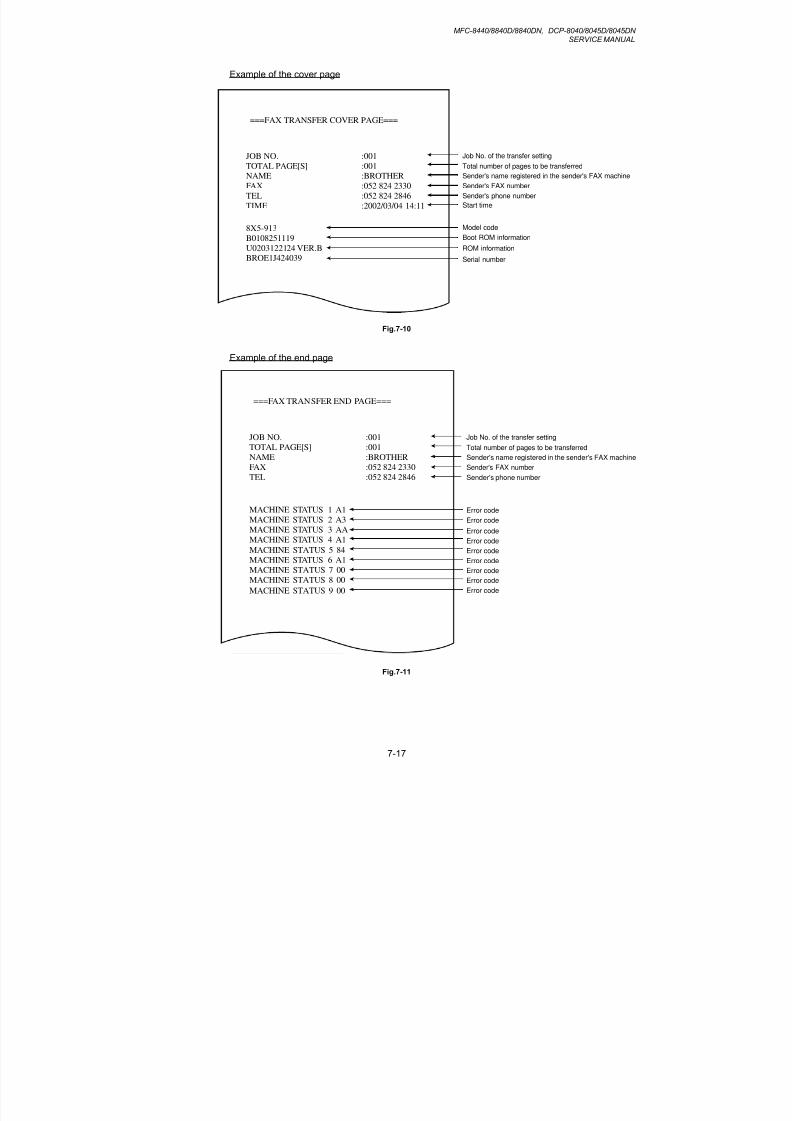
8/9/2019 DCP8040 DCP8045D MFC8440 MFC8840D MFC8840DN Manuales Técnicos.pdf
http://slidepdf.com/reader/full/dcp8040-dcp8045d-mfc8440-mfc8840d-mfc8840dn-manuales-tecnicospdf 283/361
MFC-8440/8840D/8840DN, DCP-8040/8045D/8045DNSERVICE MANUAL
7-17
Example of the cover page
===FAX TRANSFER COVER PAGE===
JOB NO.
TOTAL PAGE[S]
NAME
FAX
TEL
TIME
:001
:001
:BROTHER
:052 824 2330
:052 824 2846
:2002/03/04 14:11
8X5-913
B0108251119
U0203122124 VER.B
BROE1J424039
Job No. of the transfer setting
Total number of pages to be transferred
Sender's name registered in the sender's FAX machine
Sender's FAX number
Sender's phone number
Start time
Model code
Boot ROM information
ROM information
Serial number
Fig.7-10
Example of the end page
===FAX TRANSFER END PAGE===
JOB NO.
TOTAL PAGE[S]
NAME
FAX
TEL
:001
:001
:BROTHER
:052 824 2330
:052 824 2846
MACHINE STATUS 1 A1
MACHINE STATUS 2 A3
MACHINE STATUS 3 AA
MACHINE STATUS 4 A1
MACHINE STATUS 5 84MACHINE STATUS 6 A1
MACHINE STATUS 7 00
MACHINE STATUS 8 00
MACHINE STATUS 9 00
Job No. of the transfer setting
Total number of pages to be transferred
Sender's name registered in the sender's FAX machine
Sender's FAX number
Sender's phone number
Error code
Error code
Error code
Error code
Error codeError code
Error code
Error code
Error code
Fig.7-11

8/9/2019 DCP8040 DCP8045D MFC8440 MFC8840D MFC8840DN Manuales Técnicos.pdf
http://slidepdf.com/reader/full/dcp8040-dcp8045d-mfc8440-mfc8840d-mfc8840dn-manuales-tecnicospdf 284/361
CHAPTER 7 MAINTENANCE MODE
7-18
3.11 Fine Adjustment of Scan Start/End Positions (Maintenance mode 54)
< Function >
This function is to adjust the scan start/end positions.
< Operating Procedure >(1) Press the 5 and 4 keys in this order in the initial stage of the maintenance mode.
The “SCAN START ADJ.” will appear on the LCD.
(2) The “1. ADF 2. FB” will appear.
Select one of them that you want to adjust the start position. If you want to adjust the
start position of the ADF, press 1 key, and if you want to adjust that of the FB unit,
press 2 key.
(3) Press the 1 or 2 key to display the present compensation level for the start position.
Compensation levels can be adjusted in 11 steps from +5 to –5 (mm).
(4) Press the left arrow key to increase compensation levels, and the right arrow key tolower them.
Press the Stop button, and the machine returns to the initial state of the maintenancemode without adjusting compensation levels.
(5) Press the Set button.
The “ACCEPTED” will appear on the LCD. One second later, the machine returns tothe initial stage of the maintenance mode.
Leading edge of document
Trailling edge of document
-5-4-3
-2-1 0+1+2+3+4+5
-5-4-3-2-1 0+1
+2+3+4+5
Fig.7-12
NOTE:
The correlation between the scan start/end positions and compensation levels is shownbelow.

8/9/2019 DCP8040 DCP8045D MFC8440 MFC8840D MFC8840DN Manuales Técnicos.pdf
http://slidepdf.com/reader/full/dcp8040-dcp8045d-mfc8440-mfc8840d-mfc8840dn-manuales-tecnicospdf 285/361
MFC-8440/8840D/8840DN, DCP-8040/8045D/8045DNSERVICE MANUAL
7-19
MAINTENANCE
ACCEPTED
1. ADF 2. FB
SCAN START ADJ.
+ -
+ - + -
MAINTENANCE
MAINTENANCE
Fig.7-13
Fig.7-14
Stop button
5 and 4 keys
Right arrow key
Stop button
Left arrow key
Set button
1 second later
Set button
Right arrow keyLeft arrow key
2 second later
1 or 2 keys

8/9/2019 DCP8040 DCP8045D MFC8440 MFC8840D MFC8840DN Manuales Técnicos.pdf
http://slidepdf.com/reader/full/dcp8040-dcp8045d-mfc8440-mfc8840d-mfc8840dn-manuales-tecnicospdf 286/361
CHAPTER 7 MAINTENANCE MODE
7-20
3.12 CCD Scanner Area Setting (Maintenance mode 55)
< Function >
The machine sets the CCD scanner area and stores it into the EEPROM.
< Operating Procedure >
(1) Press the 5 key twice in the initial stage of the maintenance mode. The "SCANNER AREA SET” will appear on the LCD.
(2) When setting of the scanner area is completed, a 4-digit number will appear on theLCD. (e.g., 4723?)
* If you press the Stop button at this point, the machine will return to the maintenanceinitial stage of the maintenance mode.
Based on this 4-digit number and referring to the input data specified in the table, inputits corresponding 5-digit data value (input data). (e.g., 4723? 47247)
(3) Save the magnification compensation setting value in the EEPROM, and then return to
the initial stage of the maintenance mode.
< Input Data for Magnification Compensation after Performing Maintenance 55 >
Maintenance 55 Required Input Data Input data
1 4610 4619 46156
2 4620 4629 46257
3 4630 4639 46358
4 4640 4649 46459
5 4650 4659 46550
6 4660 4669 466517 4670 4679 46752
8 4680 4689 46853
9 4690 4699 46954
10 4700 4709 47056
11 4710 4719 47157
12 4720 4729 47247
13 4730 4739 47359
14 4740 4749 47450
15 4750 4759 47551
16 4760 4769 47652
17 4770 4779 47753
18 4780 4789 47854
19 4790 4799 47955
20 4800 4809 48057
21 4810 4819 48158
22 4820 4829 48259
23 4830 4839 48350

8/9/2019 DCP8040 DCP8045D MFC8440 MFC8840D MFC8840DN Manuales Técnicos.pdf
http://slidepdf.com/reader/full/dcp8040-dcp8045d-mfc8440-mfc8840d-mfc8840dn-manuales-tecnicospdf 287/361
MFC-8440/8840D/8840DN, DCP-8040/8045D/8045DNSERVICE MANUAL
7-21
3.13 EEPROM Customizing (Maintenance mode 74)
< Function >
This function allows you to customize the EEPROM according to language, f unctionsettings, and firmware switch settings. The customizing codes list is given in Appendix 1.
NOTE:If you replace the main PCB, be sure to carry out this procedure.
< Operating Procedure >
(1) Press the 7 and 4 keys in this order in the initial stage of the maintenance mode.
The current customizing code (e.g., 0302 in the case of MFC8840D CANADA version)appears.
(2) Enter the desired customizing code (e.g., 9301 in the case of MFC8840D U.S.A.version). The newly entered code appears.
NOTE:
The machine does not work properly when an incorrect code is entered.
(3) Press the Start button.
The machine saves the setting and appears the “PARAMETER INIT” on the LCD.
The machine returns to the initial stage of the maintenance mode.
If you press the Stop button or no keys are pressed for one minute in the aboveprocedure, the machine stops the procedure and returns to the initial stage of themaintenance mode.

8/9/2019 DCP8040 DCP8045D MFC8440 MFC8840D MFC8840DN Manuales Técnicos.pdf
http://slidepdf.com/reader/full/dcp8040-dcp8045d-mfc8440-mfc8840d-mfc8840dn-manuales-tecnicospdf 288/361
CHAPTER 7 MAINTENANCE MODE
7-22
3.14 Printing out of Machine Log Information (Maintenance mode 77)
< Function >
This function is to print out log information.
< Operating Procedure >
(1) Press the 7 key twice in the initial stage of the maintenance mode.
The “MAINTENANCE 77” will appear on the LCD.
(2) The machine prints out a list of log information. The example of the log information isshown below.
Fig.7-15
(1)
(2)
(3)
(4)
(5)
(6)
(7)
(8)
(9)
(10)
(11)
(12)
(13)
(14)
(15)
(16)
(17)
(18)
(19)
(20)
(21)
(22)

8/9/2019 DCP8040 DCP8045D MFC8440 MFC8840D MFC8840DN Manuales Técnicos.pdf
http://slidepdf.com/reader/full/dcp8040-dcp8045d-mfc8440-mfc8840d-mfc8840dn-manuales-tecnicospdf 289/361
MFC-8440/8840D/8840DN, DCP-8040/8045D/8045DNSERVICE MANUAL
7-23
(1) Loader version
(2) Program version and checksum
(3) RTC check result and RTC backup check result
(4) WHQL serial number
(5) Reading process information
(6) Presence or absence of maintenance upon process inspection
(7) Drum counter
(8) Average black coverage
(9) Total number of pages printed
(10) Number of pages picked up from each tray
(11) Number of pages picked up according to the paper size
(12) Total number of paper jams
(13) Number of jams that occurred at each tray
(14) Number of jams that occurred inside/at the rear
(15) Number of times the drum has been changed, and the last date when the drum wasreplaced
(16) Number of pages printed by a drum
(17) Number of times the toner cartridge has been changed, and the last date when the tonercartridge was replaced
(18) Number of pages printed by a toner cartridge
(19) Last 10 machine error codes
(20) Number of jams that occurred at the ADF
(21) Number of scanned pages from the ADF and the flatbed each
(22) Last 3 communication error codes

8/9/2019 DCP8040 DCP8045D MFC8440 MFC8840D MFC8840DN Manuales Técnicos.pdf
http://slidepdf.com/reader/full/dcp8040-dcp8045d-mfc8440-mfc8840d-mfc8840dn-manuales-tecnicospdf 290/361
CHAPTER 7 MAINTENANCE MODE
7-24
3.15 Display of the Equipment’s Log Information (Maintenance mode 80)
< Function >
The equipment may display its log information on the LCD.
< Operating Procedure >
(1) Press the 8 and 0 keys in this order in the initial stage of the maintenance mode.
The USB serial number appears on the LCD.
(2) Press the Start button. Each time the Start button is pressed, one of the following loginformation items appears on the LCD in the order given below.
1) Jam count, indicating how many times a paper jam has been occurred
2) Page count, indicating how many pages the photosensitive drum has been printed
3) Total page count, indicating how many pages the equipment has been printedsince produced
4) Drum count, indicating how many times the photosensitive drum has been rotated
5) Drum change count, indicating how many times drum replacement has beenmade
6) Toner change count, indicating how many times toner replacement has beenmade
7) Copy page count, indicating how many copies have been made
8) PC print page count, indicating how many pages the equipment has been printedas an output device of the connected PC
9) FAX page count, indicating how many received FAX pages have been printed
10) Error code of the most recent machine error *1
11) Error code of the most recent communications error *2
12) ADF jam count, indicating how many times a document jam has been occurred
13) ADF page count, indicating how many documents have been fed
(3) To stop this operation and return to the equipment to the initial stage of the
maintenance mode, press the Stop button.
*1 When you press the Set button while the MACHINE ERR error code is displayed,
the last error code is displayed. Each time the Set button is pressed, up to the tenerror codes are displayed one by one in reverse order.
*2 When you press the Set button while the COMEER1 error is displayed, the lasterror, the previous error, and the second previous error are displayed in turn. Theindication changes from COMEER1, COMEER2, to COMEER3.

8/9/2019 DCP8040 DCP8045D MFC8440 MFC8840D MFC8840DN Manuales Técnicos.pdf
http://slidepdf.com/reader/full/dcp8040-dcp8045d-mfc8440-mfc8840d-mfc8840dn-manuales-tecnicospdf 291/361
MFC-8440/8840D/8840DN, DCP-8040/8045D/8045DNSERVICE MANUAL
7-25
USB: USB Serial No.
T1_JAM: Number of jams that occurred at the tray 1
T2_JAM Number of jams that occurred at the tray 2
MP_JAM Number of jams that occurred at the MP tray
IN_JAM Number of jams that occurred at the feeding
RE_JAM Number of jams that occurred at the ejecting
DX_JAM Number of jams that occurred at the DX tray
TOTAL PG Total number of pages printed
DRUM_PG Number of pages printed by a drum
TNER_PG Number of pages printed by a toner cartridge
T1_PAGE Number of pages picked up from the tray 1
T2_PAGE Number of pages picked up from the tray 2
MP_PAGE Number of pages picked up from the MP tray
DX_PAGE Number of pages picked up from the DX tray
A4/LTR Number of A4/Letter size sheets picked up
LG/A4L Number of Legal/A4-Long size sheets picked up
B5/EXE Number of B5/Executive size sheets picked up
ENVLOP Number of envelopes picked up
OTHER Number of other-size sheets picked up
DRUM: Drum counter
COVERAGE: Average black coverage
DRUM_CH Number of times the drum has been replaced
DATE Last date when the drum was replaced
TNER_CH Number of times the toner cartridge has been replaced
DATE Last date when the toner cartridge was replaced
COPY Number of copies madePC PRINT Number of PC prints made
FAX Number of FAX outputs made
MACHINE ERR Last machine error code
COMERR1 Last communication error code
ADF_JAM Number of document jams that occurred at the ADF
AD_PAGE Number of scanned pages from the ADF
FB_PAGE Number of scanned pages from the FB

8/9/2019 DCP8040 DCP8045D MFC8440 MFC8840D MFC8840DN Manuales Técnicos.pdf
http://slidepdf.com/reader/full/dcp8040-dcp8045d-mfc8440-mfc8840d-mfc8840dn-manuales-tecnicospdf 292/361
CHAPTER 7 MAINTENANCE MODE
7-26
3.16 Machine Error Code Indication (Maintenance mode 82)
< Function >
This function displays an error code of the last error on the LCD.
< Operating Procedure >
(1) Press the 8 and 2 keys in this order in the initial stage of the maintenance mode.
The LCD shows the "MACHINE ERROR X X."
(2) Press the Stop button. Return to the initial stage of the maintenance mode.
3.17 Output of Transmission Log to the Telephone Line (Maintenance mode 87)
< Function >
This function outputs the transmission log (that the machine has stored about the latesttransmission) to the telephone line. It allows the service personnel to receive thetransmission log of the user's machine at a remote location and use it for analyzingproblems arising in the user's machine.
< Operating Procedure >
(1) If the user's machine has a transmission-related problem, call the user's machine at aremote location from your machine.
(2) If the line is connected, have the user perform the following:
1) Hook up to the external phone.
2) Press the Menu button, Enlarge/Reduce button, and 0 keys in this order.
3) Press the 8 and 7 keys.
The above operation makes the user's machine send CNG to your machine forsending the transmission log.
(3) If you hear the CNG sent from the user's machine, press the Start button of yourmachine.Your machine will start to receive the transmission log from the user's machine.

8/9/2019 DCP8040 DCP8045D MFC8440 MFC8840D MFC8840DN Manuales Técnicos.pdf
http://slidepdf.com/reader/full/dcp8040-dcp8045d-mfc8440-mfc8840d-mfc8840dn-manuales-tecnicospdf 293/361
MFC-8440/8840D/8840DN, DCP-8040/8045D/8045DNSERVICE MANUAL
7-27
3.18 Cancellation of the Memory Security Mode (Not applicable to the Japanese
version)
< Function >
This procedure can cancel the memory security mode. Use this procedure if the userforgets his/her password entered when setting the memory security mode so as not to exitfrom the memory security mode.
NOTE:
Carrying out this procedure will lose passwords previously entered but retain FAXmessages received in the memory security mode.
< Operating Procedure >
(1) When the SECURE MODE is displayed on the LCD, hold down the Menu button and
press the # key. Within two seconds, start to press the 2, 7, 9, 0, and 0 keys.
The memory security mode will be canceled and the machine returns to the calendarclock screen.

8/9/2019 DCP8040 DCP8045D MFC8440 MFC8840D MFC8840DN Manuales Técnicos.pdf
http://slidepdf.com/reader/full/dcp8040-dcp8045d-mfc8440-mfc8840d-mfc8840dn-manuales-tecnicospdf 294/361
MFC-8440/8840D/8840DN, DCP-8040/8045D/8045DNSERVICE MANUAL
A-1
APPENDIX 1 EEPROM CUSTOMIZING CODES
This function allows you to customize the EEPROM according to language, function settings,and firmware switch settings.
< Operating Procedure >
(1) To make the machine enter the maintenance mode, press the Menu button,
*, 2, 8, 6, and 4 keys in this order.
Within 2 seconds
The machine beeps for approx. one second and displays " "on the LCD, indicating that it is placed in the initial stage of the maintenance mode, amode in which the machine is ready to accept entry from the keys.
(2) Press the 7 and 4 keys in this order in the initial stage of the maintenance mode.
The current customizing code (e.g., 0302 in the case of MFC8840D CANADA version)appears.
(3) Enter the desired customizing code (e.g., 9301 in the case of MFC8840D U.S.A.version). The newly entered code appears.
NOTE:
The machine does not work properly when an incorrect code is entered.
(4) Press the Start button.
The machine saves the setting and returns to the initial stage of the maintenancemode.
If you press the Stop button or no keys are pressed for one minute in the aboveprocedure, the machine stops the procedure and returns to the initial stage of themaintenance mode.

8/9/2019 DCP8040 DCP8045D MFC8440 MFC8840D MFC8840DN Manuales Técnicos.pdf
http://slidepdf.com/reader/full/dcp8040-dcp8045d-mfc8440-mfc8840d-mfc8840dn-manuales-tecnicospdf 295/361
APPENDIX 1 EEPROM CUSTOMIZING CODES
A-2
< EEPROM Customizing Codes List >
ModelsVersions
DCP8040 DCP8045D DCP8045DN MFC8440 MFC8840D MFC8840DN
U.S.A. 0001 0101 - 9201 9301 9301
CANADA 0002 - - 0202 0302 -
BRZIL - - - - 0342 -
GERMAN 0003 0103 0103 0203 0303 0303
UNITED KINGDOM 0004 0104 0104 0204 0304 0304
FRANCE 0005 0105 0105 0205 0305 0305
BELGIUM 0008 0108 - 0208 0308 0308
NETHERLANDS 0009 0109 - 0209 0309 -
SWITZERLAND 0010 0110 - 0210 0310 -
IRELAND - - - 0204 0304 -DENMARK 0013 0113 0113 0213 0313 0313
AUSTRIA - - - 0203 0303 0303
SPAIN 0015 0115 0115 0215 0315 0315
ITALY 0016 0116 - 0216 0316 -
PORTUGAL 0018 0118 0118 0218 0318 0318
SOUTH AFRICA 0004 0104 - 2204 2304 -
ASIA 0004 0104 - - 0340 -
PAN NORDIC 0057 0157 - 0257 0357 -
OCEANIA - - - - 0356 -
EURO GENERIC 0099 0199 0199 0299 0399 0399
GENERAL 0050 - - 0250 0350 -

8/9/2019 DCP8040 DCP8045D MFC8440 MFC8840D MFC8840DN Manuales Técnicos.pdf
http://slidepdf.com/reader/full/dcp8040-dcp8045d-mfc8440-mfc8840d-mfc8840dn-manuales-tecnicospdf 296/361
MFC-8440/8840D/8840DN, DCP-8040/8045D/8045DNSERVICE MANUAL
A-3
APPENDIX 2 INSTALLING THE UPDATE DATA
1. INSTALLING THE UPDATE DATA TO THE MACHINE
If you want to update the current program stored in the flash ROM of the main PCB to thenewer version or after you replace the main PCB, install the update program onto the flashROM.
The program installation requires a PC/AT-compatible computer (which is capable of runningMS-DOS or its compatible OS).
1.1 Connecting the Machine to Your PC
(1) Make sure that your PC is turned off.
(2) Make sure that the power cord of the machine is unplugged from a wall socket or otherpower source.
(3) Connect the parallel interface cable to the parallel port on the back of the machine andsecure it with the lock wires.
(4) Connect the other end of the interface cable to the printer port of your PC and secure itwith the two screws.
1.2 Setting up the Machine and Your PC
(1) Plug the power cord of the machine into a wall socket, and turn on the power switch while
pressing the 5 key on the machine's control panel.
(2) Check to see that the following pattern displays on the LCD. If it does not display, goback to step (2) above.
(3) Turn on your PC.
Lock wires
Parallel interface cableHost computer
2
2
1

8/9/2019 DCP8040 DCP8045D MFC8440 MFC8840D MFC8840DN Manuales Técnicos.pdf
http://slidepdf.com/reader/full/dcp8040-dcp8045d-mfc8440-mfc8840d-mfc8840dn-manuales-tecnicospdf 297/361
APPENDIX 2 INSTALLING THE UPDATE DATA
A-4
1.3 Installing the Update Data onto the Flash ROM of the Machine
< On a PC running Windows 95 >
(1) Copy the update data and transfer utility onto the desired same directory of the harddisk. e.g., C:\UPDATE
(2) Click the Start button, point to Programs, and then click MS-DOS Prompt to open anMS-DOS window.
(3) Type the drive letter where the update data and transfer utility are located. In the
above example, type C:\ from the command line and press the Enter key.
Then type CD UPDATE and press the Enter key.
(4) To start the transfer utility transmitting the update data to the flash ROM of themachine, type the following:
ICEN filename /b
Where filename is an update data file, e.g., 8840xxxx.dat.
Then press the Enter key.During downloading, the machine beeps intermittentl y.
Upon completion of the downloading, the machine beeps continuousl y.
NOTE:
If the machine cannot return to the standby state after completion of downloading,turn the power off and on.
< On a PC running Windows 98/Me/2000 >
(1) Install the printer driver for the parallel port to your PC. (Once installed, no moreprinter driver is required for your PC.)
(2) Copy the update data onto the desired directory of the hard disk.e.g., C:\UPDATE
(3) Copy the transfer utility “Filedg32.exe” onto the desired directory of the hard disk.
(4) Run “Filedg32.exe”.The Filedrgs window will appear as shown below. (e.g., DCP-8040)
(5) Drag and drop the update data onto the icon of the model being used in the Filedrgswindows.
During downloading, the machine beeps intermittentl y.Upon completion of the downloading, the machine beeps continuousl y.
NOTE:
If the machine cannot return to the standby state after completion of downloading,turn the power off and on.
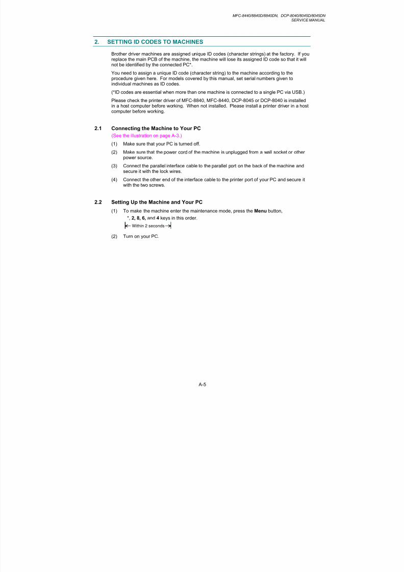
8/9/2019 DCP8040 DCP8045D MFC8440 MFC8840D MFC8840DN Manuales Técnicos.pdf
http://slidepdf.com/reader/full/dcp8040-dcp8045d-mfc8440-mfc8840d-mfc8840dn-manuales-tecnicospdf 298/361
MFC-8440/8840D/8840DN, DCP-8040/8045D/8045DNSERVICE MANUAL
A-5
2. SETTING ID CODES TO MACHINES
Brother driver machines are assigned unique ID codes (character strings) at the factory. If youreplace the main PCB of the machine, the machine will lose its assigned ID code so that it willnot be identified by the connected PC*.
You need to assign a unique ID code (character string) to the machine according to theprocedure given here. For models covered by this manual, set serial numbers given toindividual machines as ID codes.
(*ID codes are essential when more than one machine is connected to a single PC via USB.)
Please check the printer driver of MFC-8840, MFC-8440, DCP-8045 or DCP-8040 is installedin a host computer before working. When not installed. Please install a printer driver in a hostcomputer before working.
2.1 Connecting the Machine to Your PC
(See the illustration on page A-3.)
(1) Make sure that your PC is turned off.
(2) Make sure that the power cord of the machine is unplugged from a wall socket or otherpower source.
(3) Connect the parallel interface cable to the parallel port on the back of the machine andsecure it with the lock wires.
(4) Connect the other end of the interface cable to the printer port of your PC and secure itwith the two screws.
2.2 Setting Up the Machine and Your PC
(1) To make the machine enter the maintenance mode, press the Menu button,*, 2, 8, 6, and 4 keys in this order.
Within 2 seconds
(2) Turn on your PC.

8/9/2019 DCP8040 DCP8045D MFC8440 MFC8840D MFC8840DN Manuales Técnicos.pdf
http://slidepdf.com/reader/full/dcp8040-dcp8045d-mfc8440-mfc8840d-mfc8840dn-manuales-tecnicospdf 299/361
APPENDIX 2 INSTALLING THE UPDATE DATA
A-6
2.3 Running the Setup Utility
(1) On your PC, run the ID/head property setup utility (BRUSBSN.EXE). The followingwindow will appear.
(2) On the Model menu, click MFC 2.
In Port, make sure that the HFC/DCP ports connected are shown.
When not select, please click button and select the USB port of MFC-8840 or MFC-8440 or DCP-8045 or DCP-8040.
In the Serial No = 000 box, type the 9-digit serial number (e.g., G01012345) printed on
the nameplate labeled to the back of the machine as an ID code. Then press the OKbutton.
The setup utility will transmit the ID code data from your PC to the machine and then itwill terminate.
The machine will automatically return to the standby mode.
(3) To check whether the entered character string (ID code) is correct, make the machinethen press the 8 key and 0 key in this order (refer to CHAPTER 7, Subsection 3.15).
The USB serial number appears on the LCD.
(4) Check that the character string entered in step (2) is appears on “XXXXXXXXX.”
If it is OK, press the Stop button and press the 9 key twice to exit from the maintenancemode.
If something other than that is printed in XXXXXXXXX, check the connection betweenthe PC and machine and go back to step (1).

8/9/2019 DCP8040 DCP8045D MFC8440 MFC8840D MFC8840DN Manuales Técnicos.pdf
http://slidepdf.com/reader/full/dcp8040-dcp8045d-mfc8440-mfc8840d-mfc8840dn-manuales-tecnicospdf 300/361
MFC-8440/8840D/8840DN, DCP-8040/8045D/8045DNSERVICE MANUAL
A-7
APPENDIX 3 FIRMWARE SWITCHS (WSW)
WSW No. Function Reference Page
WSW01 Dial pulse setting A-8
WSW02 Tone signal setting A-9
WSW03 PABX mode setting A-10
WSW04 TRANSFER facility setting A-10
WSW05 1st dial tone and busy tone detection A-11
WSW06 Pause button setting and 2nd dial tone detection A-12
WSW07 Dial tone setting 1 A-14
WSW08 Dial tone setting 2 A-15
WSW09 Protocol definition 1 A-16
WSW10 Protocol definition 2 A-17
WSW11 Busy tone setting A-18
WSW12 Signal detection condition setting A-19
WSW13 Modem setting A-20
WSW14 AUTO ANS facility setting A-21
WSW15 REDIAL facility setting A-22
WSW16 Function setting 1 A-23
WSW17 Function setting 2 A-24
WSW18 Function setting 3 A-25
WSW19 Transmission speed setting A-26
WSW20 Overseas communications mode setting A-27
WSW21 TAD setting 1 A-28
WSW22 ECM setting A-28
WSW23 Communications setting A-29
WSW24 TAD setting 2 A-30
WSW25 TAD setting 3 A-30
WSW26 Function setting 4 A-31WSW27 Function setting 5 A-32
WSW28 Function setting 6 A-33
WSW29 Function setting 7 A-34
WSW30 Function setting 8 A-34
WSW31 Function setting 9 A-35
WSW32 Function setting 10 A-36
WSW33 Function setting 11 A-36
WSW34 Function setting 12 A-37
WSW35 Function setting 13 A-37
WSW36 Function setting 14 A-38
WSW37 Function setting 15 A-39
WSW38 Function setting 16 A-40WSW39 Function setting 17 A-41
WSW40 Function setting 18 A-42
WSW41 Function setting 19 A-43
WSW42 Function setting 20 A-44
WSW43 Function setting 21 A-45
WSW44 Speeding up scanning-1 A-46
WSW45 Speeding up scanning-2 A-47
WSW46 Monitor of PC ON/OFF state A-48
WSW47 Function setting 22 A-48
WSW48 Function setting 23 A-49
WSW49 Function setting 24 A-49
WSW50 Not used. A-49

8/9/2019 DCP8040 DCP8045D MFC8440 MFC8840D MFC8840DN Manuales Técnicos.pdf
http://slidepdf.com/reader/full/dcp8040-dcp8045d-mfc8440-mfc8840d-mfc8840dn-manuales-tecnicospdf 301/361
APPENDIX 3 FIRMWARE SWITCHS (WSW)
A-8
WSW01 (Dial pulse setting)
SelectorNo. Function Setting and Specifications
1
2
Dial pulse generation mode
No. 1 2
0 0 : N
0 1 : N+1
1 0 : 10-N
1 1 : N
3
4
Break time length in pulse dialing
No. 3 4
0 0 : 60 ms
0 1 : 67 ms
1 0 : 40 ms (for 16 PPS)
1 1 : 64 ms (at 106-ms intervals)
5
6
Inter-digit pause
No. 5 6
0 0 : 800 ms
0 1 : 850 ms
1 0 : 950 ms
1 1 : 600 ms
7
Switching between pulse (DP) andtone (PB) dialing, by the functionswitch
0: Yes 1: No
8Default dialing mode, pulse (DP) ortone (PB) dialing
0: PB 1: DP
Selectors 1 and 2: Dial pulse generation mode
These selectors set the number of pulses to be generated in pulse dialing.
N: Dialing "N" generates "N" pulses. (Dialing "0" generates 10 pulses.)N + 1: Dialing "N" generates "N + 1" pulses.10 - N: Dialing "N" generates "10 - N" pulses.
Selectors 3 and 4: Break time length in pulse dialing
These selectors set the break time length in pulse dialing.(Example: If "1," "2," and "3" are dialed when N is set by selectors 1 and 2.)
Selectors 5 and 6: Inter-digit pause
These selectors set the inter-digit pause in pulse dialing.(Example: If "1," "2," and "3" are dialed when N is set by selectors 1 and 2.)

8/9/2019 DCP8040 DCP8045D MFC8440 MFC8840D MFC8840DN Manuales Técnicos.pdf
http://slidepdf.com/reader/full/dcp8040-dcp8045d-mfc8440-mfc8840d-mfc8840dn-manuales-tecnicospdf 302/361
MFC-8440/8840D/8840DN, DCP-8040/8045D/8045DNSERVICE MANUAL
A-9
Selector 7: Switching between pulse (DP) and tone (PB) dialing, by the function switch
This selector determines whether or not the dialing mode may be switched between the pulse(DP) and tone (PB) dialing by using the function switch.
Selector 8: Default dialing mode, pulse (DP) or tone (PB) dialing
This selector sets the default dialing mode (pulse dialing or tone dialing) which may bechanged by the function switch. If the user switches it with the function switch when selector7 is set to "0," the setting specified by this selector will also be switched automatically.
WSW02 (Tone signal setting)
SelectorNo. Function Setting and Specifications
1
2
Tone signal transmission time
length
No. 1 2
0 0 : 70 ms
0 1 : 80 ms
1 0 : 90 ms
1 1 : 100 ms
3
4
Min. pause in tone dialing
No. 3 4
0 0 : 70 ms
0 1 : 80 ms
1 0 : 90 ms
1 1 : 140 ms
5
|
8
Attenuator for pseudo ringbacktone to the line (selectable inthe range of 0-15 dB)
0 : 0 dB 1: 8 dB
0 : 0 dB 1: 4 dB
0 : 0 dB 1: 2 dB
0 : 0 dB 1: 1 dB
Selectors 1 through 4: Tone signal transmission time length and Min. pause in tone dialing
These selectors set the tone signal transmission time length and minimum pause in tonedialing.
(Example: If "1," "2," "3," "4," and "5" are dialed.)
Selectors 5 through 8: Attenuator for pseudo ring backtone to the line
These selectors are used to adjust the sound level of beep generated as a ring backtone inthe F/T mode or as a signal during remote control operation or at the start of ICM recording.
Setting two or more selectors to "1" produces addition of attenuation assigned to eachselector.

8/9/2019 DCP8040 DCP8045D MFC8440 MFC8840D MFC8840DN Manuales Técnicos.pdf
http://slidepdf.com/reader/full/dcp8040-dcp8045d-mfc8440-mfc8840d-mfc8840dn-manuales-tecnicospdf 303/361
APPENDIX 3 FIRMWARE SWITCHS (WSW)
A-10
WSW03 (PABX* mode setting)
SelectorNo.
Function Setting and Specifications
1
CNG detection when sharing amodular wall socket with a
telephone
0: A 1: B
2
|
4
Not used.
5
CNG detection when sharing amodular wall socket with atelephone
0: A 1: B
6
|
8
Not used.
* PABX: Private automatic branch exchange
NOTE:
Selectors 2 through 4, 6 and 7 are not applicable where no PABX is installed.
Selectors 1 and 5: CNG detection when sharing a modular wall socket with a telephone
These selectors determine whether or not the machine detects a CNG signal when a line isconnected to a telephone sharing a modular wall socket with the machine. Upon detection ofCNG signals by the number of cycles specified by these selectors, the machine interpretsCNG as an effective signal and then starts FAX reception.
SelectorNo. 1 No. 5
Cycle
0 (A) 0 (A)0 (A) 1 (B)
1 (B) 0 (A)1 (B) 1 (B)
0.5 cycle1.0 cycle
1.5 cycles2.0 cycles
WSW04 (TRANSFER facility setting)
SelectorNo. Function Setting and Specifications
1
|
6
Not used.
7
8
Break time length for flashfunction
No. 7 8
0 0 : 80 ms
0 1 : 110 ms
1 0 : 250 ms
1 1 : 500 ms
NOTE:
Selectors 5 through 8 are not applicable in those countries where no transfer facility issupported.
Selectors 7 and 8: Break time length for flash function
These selectors set the break time length.
This setting is effective only when the flash function is selected for the R key by using thefunction switch.
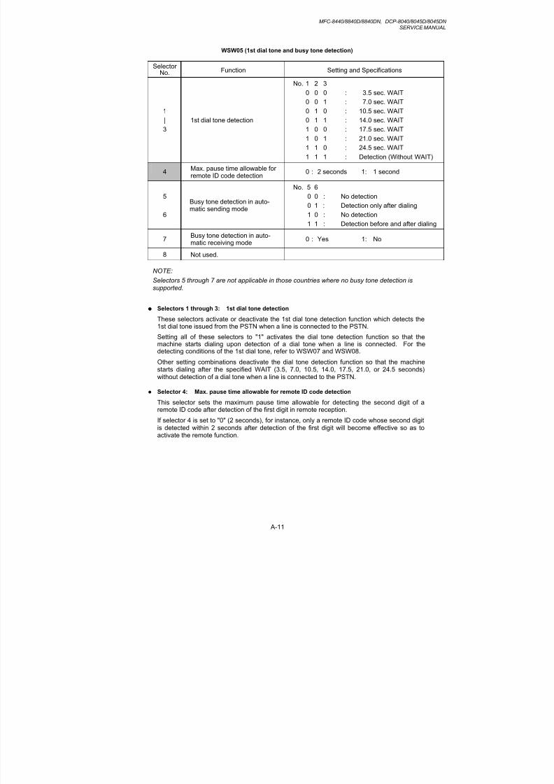
8/9/2019 DCP8040 DCP8045D MFC8440 MFC8840D MFC8840DN Manuales Técnicos.pdf
http://slidepdf.com/reader/full/dcp8040-dcp8045d-mfc8440-mfc8840d-mfc8840dn-manuales-tecnicospdf 304/361
MFC-8440/8840D/8840DN, DCP-8040/8045D/8045DNSERVICE MANUAL
A-11
WSW05 (1st dial tone and busy tone detection)
SelectorNo. Function Setting and Specifications
1
|
3
1st dial tone detection
No. 1 2 3
0 0 0 : 3.5 sec. WAIT
0 0 1 : 7.0 sec. WAIT
0 1 0 : 10.5 sec. WAIT
0 1 1 : 14.0 sec. WAIT
1 0 0 : 17.5 sec. WAIT
1 0 1 : 21.0 sec. WAIT
1 1 0 : 24.5 sec. WAIT
1 1 1 : Detection (Without WAIT)
4Max. pause time allowable forremote ID code detection
0 : 2 seconds 1: 1 second
5
6
Busy tone detection in auto-matic sending mode
No. 5 6
0 0 : No detection
0 1 : Detection only after dialing
1 0 : No detection
1 1 : Detection before and after dialing
7Busy tone detection in auto-matic receiving mode
0 : Yes 1: No
8 Not used.
NOTE:
Selectors 5 through 7 are not applicable in those countries where no busy tone detection is
supported.
Selectors 1 through 3: 1st dial tone detection
These selectors activate or deactivate the 1st dial tone detection function which detects the1st dial tone issued from the PSTN when a line is connected to the PSTN.
Setting all of these selectors to "1" activates the dial tone detection function so that themachine starts dialing upon detection of a dial tone when a line is connected. For thedetecting conditions of the 1st dial tone, refer to WSW07 and WSW08.
Other setting combinations deactivate the dial tone detection function so that the machinestarts dialing after the specified WAIT (3.5, 7.0, 10.5, 14.0, 17.5, 21.0, or 24.5 seconds)without detection of a dial tone when a line is connected to the PSTN.
Selector 4: Max. pause time allowable for remote ID code detection
This selector sets the maximum pause time allowable for detecting the second digit of aremote ID code after detection of the first digit in remote reception.
If selector 4 is set to "0" (2 seconds), for instance, only a remote ID code whose second digitis detected within 2 seconds after detection of the first digit will become effective so as toactivate the remote function.

8/9/2019 DCP8040 DCP8045D MFC8440 MFC8840D MFC8840DN Manuales Técnicos.pdf
http://slidepdf.com/reader/full/dcp8040-dcp8045d-mfc8440-mfc8840d-mfc8840dn-manuales-tecnicospdf 305/361
APPENDIX 3 FIRMWARE SWITCHS (WSW)
A-12
Selectors 5 and 6: Busy tone detection in automatic sending mode
These selectors determine whether or not the machine automatically disconnects a line upondetection of a busy tone in automatic sending mode.
Setting selector 6 to "0" ignores a busy tone so that the machine does not disconnect the line.
Setting selectors 5 and 6 to "0" and "1," respectively, makes the machine detect a busy tone
only after dialing and disconnect the line.
Setting both of selectors 5 and 6 to "1" makes the machine detect a busy tone before andafter dialing and then disconnect the line.
Selector 7: Busy tone detection in automatic receiving mode
This selector determines whether or not the machine automatically disconnects a line upondetection of a busy tone in automatic receiving mode.
WSW06 (Pause button setting and 2nd dial tone detection)
SelectorNo.
Function Setting and Specifications
1
|
3
Pause button setting and 2nd dialtone detection
No. 1 2 3
0 0 0 : No pause
0 0 1 : 3.5 sec. WAIT
0 1 0 : 7 sec. WAIT
0 1 1 : 10.5 sec. WAIT
1 0 0 : 14 sec. WAIT
1 1 0 : 2nd dial tone detectiononly in pulse dialing (DP)system
1 0 1 : 2nd dial tone detection1 1 1 : both in DP and push-button
(PB) dialing system
4
|
6
Detection of 2nd dial tone
No. 4 5 6
0 0 0 : 50 ms
0 0 1 : 210 ms
0 1 0 : 500 ms
0 1 1 : 800 ms
1 0 0 : 900 ms
1 0 1 : 1.5 sec.
1 1 0 : 2.0 sec.
1 1 1 : 2.5 sec.
7 No. of 2nd dial tone detection times 0: Once 1: Twice
82nd dial tone interrupt detectingtime
0: 30 ms 1: 50 ms

8/9/2019 DCP8040 DCP8045D MFC8440 MFC8840D MFC8840DN Manuales Técnicos.pdf
http://slidepdf.com/reader/full/dcp8040-dcp8045d-mfc8440-mfc8840d-mfc8840dn-manuales-tecnicospdf 306/361
MFC-8440/8840D/8840DN, DCP-8040/8045D/8045DNSERVICE MANUAL
A-13
Selectors 1 through 3: Pause button setting and 2nd dial tone detection
Selectors1 2 3
0 0 0 No WAIT is inserted even if the Pause button is pressed.
0 0 10 1 00 1 11 0 0
If you press the Pause button during dialing, the machine will insert WAITas defined in the above table.
If the Pause button is pressed repeatedly, the machine inserts thespecified WAIT multiplied by the number of depressions. It applies also inhook-up dialing.
1 0 11 1 01 1 1
When these selectors are set to "1, 0, 1":
If you press the Pause button during dialing, the machine will wait for the2nd dial tone to be sent via the communications line.
When these selectors are set to "1, 1, 0" or "1, 1, 1":
If you press the Pause button during dialing, the machine will first wait forthe 2nd dial tone to be sent via the communications line. After that, the
machine will insert a WAIT of 3.5 seconds.If no 2nd dial tone is received within the specified time length (set byWSW08), the machine will disconnect the line if in automatic dialing, or itwill start transmitting the dial signal if given after depression of the Pause button in hook-up dialing.
Selectors 4 through 6: Detection of 2nd dial tone
Upon detection of the 2nd dial tone for the time length specified by these selectors, themachine starts dialing.
This setting is effective only when the 2nd dial tone detection function is activated by
selectors 1 through 3 (Setting 101, 110, or 111).
This function does not apply in those countries where no dial tone detection function issupported.
Selector 7: No. of 2nd dial tone detection times
This selector sets the number of dial tone detection times required for starting dialing.
Selector 8: 2nd dial tone interrupt detecting time
This selector sets the allowable time length of an interrupt which should not be interpreted asan interrupt in the 2nd tone dialing.

8/9/2019 DCP8040 DCP8045D MFC8440 MFC8840D MFC8840DN Manuales Técnicos.pdf
http://slidepdf.com/reader/full/dcp8040-dcp8045d-mfc8440-mfc8840d-mfc8840dn-manuales-tecnicospdf 307/361
APPENDIX 3 FIRMWARE SWITCHS (WSW)
A-14
WSW07 (Dial tone setting 1)
SelectorNo. Function Setting and Specifications
1
2Frequency band range
No. 1 2
0 0 : Narrows by 10 Hz0 1 : Initial value
1 X : Widens by 10 Hz
3 Not used.
4
|
6
2nd dial tone detection level
(Z = 600 Ω)
No. 4 5 6
0 0 0 : -21 dBm
0 0 1 : -24 dBm
0 1 0 : -27 dBm
0 1 1 : -30 dBm
1 0 0 : -33 dBm
1 0 1 : -36 dBm
1 1 0 : -39 dBm
1 1 1 : -42 dBm
7 1st dial tone interrupt detecting
time0: 30 ms 1: 50 ms
8 Not used.
NOTE:
Selectors 1 through 7 are not applicable in those countries where no dial tone or line currentdetection is supported, e.g., U.S.A.
Selectors 1 and 2: Frequency band range
These selectors set the frequency band for the 1st dial tone and the busy tone (beforedialing) to be detected.
This setting is effective only when selectors 1 through 3 of WSW05 are set to "1,1,1."
Selectors 4 through 6: 2nd dial tone detection level
These selectors set the detection level of the 2nd dial tone.
Selector 7: 1st dial tone interrupt detecting time
This selector sets the allowable time length of an interrupt which should not be interpreted as
an interrupt in the 1st dial tone dialing.

8/9/2019 DCP8040 DCP8045D MFC8440 MFC8840D MFC8840DN Manuales Técnicos.pdf
http://slidepdf.com/reader/full/dcp8040-dcp8045d-mfc8440-mfc8840d-mfc8840dn-manuales-tecnicospdf 308/361
MFC-8440/8840D/8840DN, DCP-8040/8045D/8045DNSERVICE MANUAL
A-15
WSW08 (Dial tone setting 2)
SelectorNo.
Function Setting and Specifications
1
|
3
1st dial tone detection timelength
No. 1 2 3
0 0 0 : 50 ms0 0 1 : 210 ms
0 1 0 : 500 ms
0 1 1 : 800 ms
1 0 0 : 900 ms
1 0 1 : 1.5 sec.
1 1 0 : 2.0 sec.
1 1 1 : 2.5 sec.
4
5
Time-out length for 1st and 2nddial tone detection
No. 4 50 0 : 10 sec.
0 1 : 20 sec.
1 0 : 15 sec.
1 1 : 30 sec.
6
|
8
Detection level of 1st dial toneand busy tone before dialing
No. 6 7 8
0 0 0 : -21 dBm
0 0 1 : -24 dBm
0 1 0 : -27 dBm
0 1 1 : -30 dBm
1 0 0 : -33 dBm
1 0 1 : -36 dBm
1 1 0 : -39 dBm
1 1 1 : -42 dBm
NOTE:
The WSW08 is not applicable in those countries where no dial tone detection is supported,e.g., U.S.A.
Selectors 1 through 3: 1st dial tone detection time length
Upon detection of the 1st dial tone for the time length set by these selectors, the machinestarts dialing.
This setting is effective only when selectors 1 through 3 of WSW05 are set to "1,1,1."
Selectors 4 and 5: Time-out length for 1st and 2nd dial tone detection
These selectors set the time-out length for the 1st and 2nd dial tone detection so that themachine waits dial tone input for the specified time length and disconnects itself from the linewhen no dial tone is inputted.

8/9/2019 DCP8040 DCP8045D MFC8440 MFC8840D MFC8840DN Manuales Técnicos.pdf
http://slidepdf.com/reader/full/dcp8040-dcp8045d-mfc8440-mfc8840d-mfc8840dn-manuales-tecnicospdf 309/361
APPENDIX 3 FIRMWARE SWITCHS (WSW)
A-16
WSW09 (Protocol definition 1)
SelectorNo.
Function Setting and Specifications
1 Frame length selection 0: 256 octets 1: 64 octets
2 Use of non-standard commands 0: Allowed 1: Prohibited
3
4
No. of retries
No. 3 4
0 0 : 4 times
0 1 : 3 times
1 0 : 2 times
1 1 : 1 time
5 T5 timer 0: 300 sec. 1: 60 sec.
6 T1 timer 0: 35 sec. 1: 40 sec.
7
8
Elapsed time for time-out
control for no response from thecalled station in automaticsending mode
No. 7 8
0 0 : 60 sec.
(55 sec. for US and Canada)
0 1 : 140 sec.
1 0 : 90 sec.
1 1 : 35 sec.
NOTE:
Selectors 1 through 6 are not applicable in those models which do not support ECM.
Selector 1: Frame length selection
Usually a single frame consists of 256 octets (1 octet = 8 bits). For communications lines
with higher bit error rate, however, set selector 1 to "1" so that the machine can divide amessage into 64-octet frames.
Remarks: The error correction mode (ECM) is a facsimile transmission manner in whichthe machine divides a message into frames for transmission so that if any dataerror occurs on the transmission line, the machine retransmits only those framescontaining the error data.
Selector 2: Use of non-standard commands
If this selector is set to "0," the machine may use non-standard commands (the machine’snative-mode commands, e.g., NSF, NSC, and NSS) for communications. If it is set to "1,"the machine will use standard commands only.
Selectors 3 and 4: No. of retries
These selectors set the number of retries in each specified modem transmission speed.
Selector 5: T5 timer
This selector sets the time length for the T5 timer.
Selector 6: T1 timer
This selector sets the time length for the T1 timer.
Selectors 7 and 8: Elapsed time for time-out control
If the machine receives no response (no G3 command) from the called terminal in automaticsending during the time set by these selectors, it disconnects the line.

8/9/2019 DCP8040 DCP8045D MFC8440 MFC8840D MFC8840DN Manuales Técnicos.pdf
http://slidepdf.com/reader/full/dcp8040-dcp8045d-mfc8440-mfc8840d-mfc8840dn-manuales-tecnicospdf 310/361
MFC-8440/8840D/8840DN, DCP-8040/8045D/8045DNSERVICE MANUAL
A-17
WSW10 (Protocol definition 2)
SelectorNo.
Function Setting and Specifications
1 Not used.
2 Time length from transmission ofthe last dial digit to CML ON
0: 100 ms 1: 50 ms
3Time length from CML ON to CNGtransmission
0: 2 sec. 1: 4 sec.
4Time length from CML ON to CEDtransmission (except for facsimile-to-telephone switching)
0: 0.5 sec. 1: 2 sec.
5
6No. of training retries
No. 5 6
0 0 : 1 time
0 1 : 2 times
1 0 : 3 times
1 1 : 4 times
7 Encoding system MR 0: Allowed 1: Not allowed
8 (Compression) MMR 0: Allowed 1: Not allowed
Selector 2: Time length from transmission of the last dial digit to CML ON
This selector sets the time length from when the machine transmits the last dial digit until theCML relay comes on.
Selector 3: Time length from CML ON to CNG transmission
This selector sets the time length until the machine transmits a CNG after it turns on the CML
relay.
Selector 4: Time length from CML ON to CED transmission
This selector sets the time length until the machine transmits a CED after it turns on the CMLrelay. This setting does not apply to switching between facsimile and telephone.
Selectors 5 and 6: No. of training retries
These selectors set the number of training retries to be repeated before automatic fallback.
Selectors 7 and 8: Encoding system (Compression)
This selector determines whether or not use of the MR/MMR coding system will be allowed.

8/9/2019 DCP8040 DCP8045D MFC8440 MFC8840D MFC8840DN Manuales Técnicos.pdf
http://slidepdf.com/reader/full/dcp8040-dcp8045d-mfc8440-mfc8840d-mfc8840dn-manuales-tecnicospdf 311/361
APPENDIX 3 FIRMWARE SWITCHS (WSW)
A-18
WSW11 (Busy tone setting)
SelectorNo.
Function Setting and Specifications
12
Frequency band range
No. 1 2
0 0 : Narrows by 10 Hz0 1 : Initial value
1 x : Widens by 10 Hz
3 1: 250-750/250-750 ms
4 1: 400-600/400-600 ms
5 1: 175-440/175-440 ms
6 1: 100-1000/17-660 ms
7 1: 110-410/320-550 ms
8
ON/OFF time length ranges
(More than one setting allowed)
1: 100-660/100-660 ms
NOTE:
• WSW11 is not applicable in those countries where no busy tone detection is supported.
• The setting of WSW11 is effective only when selectors 5 and 6 of WSW05 are set to "0, 1"or "1, 1" (Busy tone detection).
Selectors 1 and 2: Frequency band range
These selectors set the frequency band for busy tone to be detected.
Selectors 3 through 8: ON/OFF time length ranges
These selectors set the ON and OFF time length ranges for busy tone to be detected. If
more than one selector is set to "1," the ranges become wider. For example, if selectors 4and 5 are set to "1," the ON and OFF time length ranges are from 175 to 600 ms.

8/9/2019 DCP8040 DCP8045D MFC8440 MFC8840D MFC8840DN Manuales Técnicos.pdf
http://slidepdf.com/reader/full/dcp8040-dcp8045d-mfc8440-mfc8840d-mfc8840dn-manuales-tecnicospdf 312/361
MFC-8440/8840D/8840DN, DCP-8040/8045D/8045DNSERVICE MANUAL
A-19
WSW12 (Signal detection condition setting)
SelectorNo.
Function Setting and Specifications
1
2
Min. OFF time length of callingsignal (Ci)
No. 1 2
0 0 : 1500 ms0 1 : 500 ms
1 0 : 700 ms
1 1 : 900 ms
3
4
Max. OFF time length of callingsignal (Ci)
No. 3 4
0 0 : 6 sec.
0 1 : 7 sec.
1 0 : 9 sec.
1 1 : 11 sec.
5
6
Detecting time setting
No. 5 6
0 0 : 800 ms
0 1 : 200 ms
1 0 : 250 ms
1 1 : 150 ms
7 Not used.
8 Not used.
Selectors 1 through 4: Min. and max. OFF time length of calling signal (Ci)
If the machine detects the OFF state of calling signal (Ci) for a time length which is greaterthan the value set by selectors 1 and 2 and less than the value set by selectors 3 and 4, itinterprets the Ci signal as OFF.
Selectors 5 and 6: Detecting time setting
These selectors set the time length required to make the machine acknowledge itself to becalled. That is, if the machine continuously detects calling signals with the frequency set byselectors 1 through 4 of WSW14 during the time length set by these selectors 5 and 6, itacknowledges the call.

8/9/2019 DCP8040 DCP8045D MFC8440 MFC8840D MFC8840DN Manuales Técnicos.pdf
http://slidepdf.com/reader/full/dcp8040-dcp8045d-mfc8440-mfc8840d-mfc8840dn-manuales-tecnicospdf 313/361
APPENDIX 3 FIRMWARE SWITCHS (WSW)
A-20
WSW13 (Modem setting)
SelectorNo.
Function Setting and Specifications
1
2Cable equalizer
No. 1 2
0 0 : 0 km0 1 : 1.8 km
1 0 : 3.6 km
1 1 : 5.6 km
3
4Reception level
No. 3 4
0 0 : -43 dBm
0 1 : -47 dBm
1 0 : -49 dBm
1 1 : -51 dBm
5
|8
Modem attenuator
0: 0 dB 1: 8 dB
0: 0 dB 1: 4 dB
0: 0 dB 1: 2 dB
0: 0 dB 1: 1 dB
The modem should be adjusted according to the user's line conditions.
Selectors 1 and 2: Cable equalizer
These selectors are used to improve the pass-band characteristics of analogue signals on aline. (Attenuation in the high-band frequency is greater than in the low-band frequency.)
Set these selectors according to the distance from the telephone switchboard to the machine.
Selectors 3 and 4: Reception level
These selectors set the optimum receive signal level.
Selectors 5 through 8: Modem attenuator
These selectors are used to adjust the transmitting level of the modem when the receptionlevel at the remote station is improper due to line loss. This function applies to G3 protocolsignals.
Setting two or more selectors to "1" produces addition of attenuation assigned to eachselector.
This setting will be limited if selector 8 of WSW23 is set to "0."

8/9/2019 DCP8040 DCP8045D MFC8440 MFC8840D MFC8840DN Manuales Técnicos.pdf
http://slidepdf.com/reader/full/dcp8040-dcp8045d-mfc8440-mfc8840d-mfc8840dn-manuales-tecnicospdf 314/361
MFC-8440/8840D/8840DN, DCP-8040/8045D/8045DNSERVICE MANUAL
A-21
WSW14 (AUTO ANS facility setting)
SelectorNo.
Function Setting and Specifications
1
2
Frequency band selection(Lower limit)
No. 1 2
0 0 : 13 Hz0 1 : 15 Hz
1 0 : 23 Hz
1 1 : 20 Hz
3
4
Frequency band selection(Upper limit)
No. 3 4
0 0 : 30 Hz
0 1 : 55 Hz
1 0 : 70 Hz
1 1 : 200 Hz
5
|
8
No. of rings in AUTO ANS mode
No. 5 6 7 8
0 0 0 0 : Fixed to once
0 0 0 1 : Fixed to 2 times
0 0 1 0 : Fixed to 3 times
0 0 1 1 : Fixed to 4 times
0 1 0 0 : 1 to 2 times
0 1 0 1 : 1 to 3 times
0 1 1 0 : 1 to 4 times
0 1 1 1 : 1 to 5 times
1 0 0 0 : 2 to 3 times
1 0 0 1 : 2 to 4 times
1 0 1 0 : 2 to 5 times
1 0 1 1 : 2 to 6 times
1 1 0 0 : 1 to 10 times
1 1 0 1 : 2 to 10 times1 1 1 0 : 3 to 5 times
1 1 1 1 : 4 to 10 times
Selectors 1 through 4: Frequency band selection
These selectors are used to select the frequency band of calling signals for activating the AUTO ANS facility.
In the French versions, if the user sets the PBX to OFF from the control panel, the settingmade by selectors 1 and 2 will take no effect and the frequency's lower limit will be fixed to 32Hz. (Even if the setting made by these selectors does not apply, it will be printed on theconfiguration list.)
Selectors 5 through 8: No. of rings in AUTO ANS mode
These selectors set the number of rings to initiate the AUTO ANS facility.

8/9/2019 DCP8040 DCP8045D MFC8440 MFC8840D MFC8840DN Manuales Técnicos.pdf
http://slidepdf.com/reader/full/dcp8040-dcp8045d-mfc8440-mfc8840d-mfc8840dn-manuales-tecnicospdf 315/361
APPENDIX 3 FIRMWARE SWITCHS (WSW)
A-22
WSW15 (REDIAL facility setting)
SelectorNo.
Function Setting and Specifications
1
2
Selection of redial interval
No. 1 2
0 0 : 5 minutes0 1 : 1 minute
1 0 : 2 minutes
1 1 : 3 minutes
3
|
6
No. of redialings
No. 3 4 5 6
0 0 0 0 : 16 times
0 0 0 1 : 1 times
0 0 1 0 : 2 times
0 0 1 1 : 3 times
| |
1 1 1 1 : 15 times
7Redialing for no response sentfrom the called terminal
0: Redialing 1: No redialing
8 CRP option0: Disable 1: Enable
Selectors 1 through 6: Selection of redial interval and No. of redialings
The machine redials by the number of times set by selectors 3 through 6 at intervals set byselectors 1 and 2.
This setting is effective only when selector 7 is set to "0."
Selectors 7: Redialing for no response sent from the called terminal
This selector determines whether or not the machine redials if no G3 command responsecomes from the called station after dialing within the time length set by selectors 7 and 8 ofWSW09.
Selectors 8: CRP option
If a command error occurs in the equipment (calling station), the equipment usually waits forthree seconds and then makes a retry three times. This CRP option is a request commandthat can be sent from the called station for requesting the calling station to retry the failedcommand immediately.

8/9/2019 DCP8040 DCP8045D MFC8440 MFC8840D MFC8840DN Manuales Técnicos.pdf
http://slidepdf.com/reader/full/dcp8040-dcp8045d-mfc8440-mfc8840d-mfc8840dn-manuales-tecnicospdf 316/361
MFC-8440/8840D/8840DN, DCP-8040/8045D/8045DNSERVICE MANUAL
A-23
WSW16 (Function setting 1)
SelectorNo.
Function Setting and Specifications
1 Not used.
2 CCITT superfine recommendation 0: OFF 1: ON
3|6
Not used.
7 Max. document length limitation 0: 400 cm 1: 90 cm
8 Stop button pressed duringreception
0: Not functional 1: Functional
Selector 2: CCITT superfine recommendation
If this selector is set to "1," the machine communicates in CCITT recommended superfinemode (15.4 lines/mm). If it is set to "0," it communicates in native superfine mode.
Selector 7: Max. document length limitation
This selector is used to select the maximum length of a document to be sent.
Selector 8: Stop key pressed during reception
If this selector is set to "1," pressing the Stop button can stop the current receiving operation.The received data will be lost.

8/9/2019 DCP8040 DCP8045D MFC8440 MFC8840D MFC8840DN Manuales Técnicos.pdf
http://slidepdf.com/reader/full/dcp8040-dcp8045d-mfc8440-mfc8840d-mfc8840dn-manuales-tecnicospdf 317/361
APPENDIX 3 FIRMWARE SWITCHS (WSW)
A-24
WSW17 (Function setting 2)
SelectorNo.
Function Setting and Specifications
12
Off-hook alarm
No. 1 2
0 0 : No alarm0 1 : Always valid
1 X : Valid except when'call reservation'is selected.
34
Not used.
5 Calendar clock type 0: U.S.A. type 1: European type
6 Not used.
7 Non-ring reception 0: OFF 1: ON
8 Not used.
Selectors 1 and 2: Off-hook alarm
These selectors activate or deactivate the alarm function which sounds an alarm when thehandset is off the hook after the communication is completed.
The off-hook alarm works also for an external telephone connected to the EXT modularsocket.
Selector 5: Calendar clock type
If this selector is set to "0" (USA), the MM/DD/YY hh:mm format applies; if it is set to "1"(Europe), the DD/MM/YY hh:mm format applies: DD is the day, MM is the month, YY is thelast two digits of the year, hh is the hour, and mm is the minute.
Selector 7: Non-ring reception
Setting this selector to "1" makes the machine receive calls without ringer sound if the ringdelay is set to 0.

8/9/2019 DCP8040 DCP8045D MFC8440 MFC8840D MFC8840DN Manuales Técnicos.pdf
http://slidepdf.com/reader/full/dcp8040-dcp8045d-mfc8440-mfc8840d-mfc8840dn-manuales-tecnicospdf 318/361
MFC-8440/8840D/8840DN, DCP-8040/8045D/8045DNSERVICE MANUAL
A-25
WSW18 (Function setting 3)
SelectorNo.
Function Setting and Specifications
1 Not used.
2
3
Detection enabled time for CNGand no tone
No. 2 30 0 : 40 sec.
0 1 : 0 sec. (No detection)
1 0 : 5 sec.
1 1 : 80 sec.
4
5Not used.
6 Registration of station ID 0: Permitted 1: Prohibited
7
8
Tone sound monitoring
No. 7 8
0 X : No monitoring
1 0 : Up to phase B at thecalling station only
1 1 : All transmission phasesboth at the calling andcalled stations
Selectors 2 and 3: Detection enabled time for CNG and no tone
After the line is connected via the machine or the external telephone, the machine can detecta CNG signal or no tone for the time length specified by these selectors. The settingspecified by these selectors becomes effective only when selector 8 of WSW20 is set to "1."
Selectors 7 and 8: Tone sound monitoring
These selectors set monitoring specifications of the tone sound inputted from the line.

8/9/2019 DCP8040 DCP8045D MFC8440 MFC8840D MFC8840DN Manuales Técnicos.pdf
http://slidepdf.com/reader/full/dcp8040-dcp8045d-mfc8440-mfc8840d-mfc8840dn-manuales-tecnicospdf 319/361
APPENDIX 3 FIRMWARE SWITCHS (WSW)
A-26
WSW19 (Transmission speed setting)
SelectorNo.
Function Setting and Specifications
1|
3
First transmission speed choicefor fallback
No. 1 2 3
No. 4 5 60 0 0 : 2,400 bps
0 0 1 : 4,800 bps
0 1 0 : 7,200 bps
4
|
6
Last transmission speed choicefor fallback
0 1 1 : 9,600 bps
1 0 0 : 12,000 bps
1 0 1 :
1 1 0 : 14,400 bps
1 1 1 :
7 V. 34 mode 0: Permitted 1: Prohibited
8 V. 17 mode 0: Permitted 1: Prohibited
NOTE:
For the transmission speed setting in V.34 mode, refer to WSW39.
Selectors 1 through 6: First and last choices of transmission speed for fallback
These selectors are used to set the modem speed range. With the first transmission speedchoice specified by selectors 1 through 3, the machine attempts to establish the transmissionlink via the modem. If the establishment fails, the machine automatically steps down to thenext highest speed and attempts to establish the transmission link again. The machinerepeats this sequence while stepping down the transmission speed to the last choicespecified by selectors 4 through 6.
If the modem always falls back to a low transmission speed (e.g., 4,800 bps), set the firsttransmission speed choice to the lower one (e.g., modify it from 12,000 bps to 7,200 bps) inorder to deactivate the high-speed modem function and reduce the training time for shortertransmission time.
Generally, to save the transmission time, set the last transmission speed choice to a higherone.
Selector 7: V. 34 mode
This selector determines whether or not the machine communicates with the remote stationin the V. 34 mode when that station supports the V. 34 mode.

8/9/2019 DCP8040 DCP8045D MFC8440 MFC8840D MFC8840DN Manuales Técnicos.pdf
http://slidepdf.com/reader/full/dcp8040-dcp8045d-mfc8440-mfc8840d-mfc8840dn-manuales-tecnicospdf 320/361
MFC-8440/8840D/8840DN, DCP-8040/8045D/8045DNSERVICE MANUAL
A-27
WSW20 (Overseas communications mode setting)
SelectorNo.
Function Setting and Specifications
1 EP* tone prefix 0: OFF 1: ON
2 Overseas communications mode(Reception)
0: 2100 Hz 1: 1100 Hz
3Overseas communications mode(Transmission)
0: OFF 1: Ignores DIS once.
4
5
Min. time length from reception ofCFR to start of transmission ofvideo signals
No. 4 5
0 0 : 100 ms
0 1 : 200 ms
1 0 : 300 ms
1 1 : 400 ms
67
Chattering noise elimination atdetection of CNG
No. 6 7
0 0 : Yes (When CNG goes eitherON or OFF)
0 1 : Yes(Only when CNG goes OFF)
1 0 : No
1 1 : No
8 CNG detection on/off 0: OFF 1: ON
* EP: Echo protection
Selector 1: EP tone prefix
Setting this selector to "1" makes the machine transmit a 1700 Hz echo protection (EP) toneimmediately preceding training in V.29 modulation system to prevent omission of trainingsignals.
Prefixing an EP tone is effective when the machine fails to transmit at the V.29 modem speedand always has to fall back to 4800 bps transmission.
Selectors 2 and 3: Overseas communications mode
These selectors should be used if the machine malfunctions in overseas communications. According to the communications error state, select the signal specifications.
Setting selector 2 to "1" allows the machine to use 1100 Hz CED signal instead of 2100 Hz inreceiving operation. This prevents malfunctions resulting from echoes, since the 1100 Hzsignal does not disable the echo suppressor (ES) while the 2100 Hz signal does.
Setting selector 3 to "1" allows the machine to ignore a DIS signal sent from the called stationonce in sending operation. This operation suppresses echoes since the first DIS signalimmediately follows a 2100 Hz CED (which disables the ES) so that it is likely to be affectedby echoes in the disabled ES state. However, such a disabled ES state will be removed soonso that the second and the following DIS signals are not susceptible to data distortion due toechoes. Note that some models when called may cause error by receiving a self-outputtedDIS.
Selectors 8: CNG detection on/off
If this selector is set to "1," the machine detects a CNG signal according to the conditionpreset by selectors 2 and 3 of WSW18 after a line is connected. If it is set to "0," the
machine detects a CNG signal as long as the line is connected.

8/9/2019 DCP8040 DCP8045D MFC8440 MFC8840D MFC8840DN Manuales Técnicos.pdf
http://slidepdf.com/reader/full/dcp8040-dcp8045d-mfc8440-mfc8840d-mfc8840dn-manuales-tecnicospdf 321/361
APPENDIX 3 FIRMWARE SWITCHS (WSW)
A-28
WSW21 (TAD setting 1)
SelectorNo.
Function Setting and Specifications
1|
7
Not used.
8
Erasure of message stored in thememory after the messagetransfer
0: Yes 1: No
Selector 8: Erasure of message
Setting this selector to "0" will erase the message recorded in the memory after the documentretrieval feature transfers the message.
WSW22 (ECM setting)
SelectorNo.
Function Setting and Specifications
1 ECM* in sending 0: ON 1: OFF
2 ECM* in receiving 0: ON 1: OFF
3 Call Waiting Caller ID 0: ON 1: OFF
4 Not used.
5|8
Not used.
* ECM: Error correction mode
NOTE:
• Selector 3 is applicable to the American version only, but not applicable to those modelsequipped with high-speed modem.
• Selectors 5 through 8 are applicable to the Asian version only.
Selector 3: Call Waiting Caller ID
Setting this selector to "0" allows the user to decide whether or not to interrupt the current callwhen a new call comes in. If Call Waiting Caller ID service is available in the area and theuser subscribes to it, he/she can see information about his/her incoming call.

8/9/2019 DCP8040 DCP8045D MFC8440 MFC8840D MFC8840DN Manuales Técnicos.pdf
http://slidepdf.com/reader/full/dcp8040-dcp8045d-mfc8440-mfc8840d-mfc8840dn-manuales-tecnicospdf 322/361
MFC-8440/8840D/8840DN, DCP-8040/8045D/8045DNSERVICE MANUAL
A-29
WSW23 (Communications setting)
SelectorNo.
Function Setting and Specifications
1Starting point of training check(TCF)
0: From the head of a series of zeros
1: From any arbitrary point
2
3
Allowable training error rate
No. 2 3
0 0 : 0%
0 1 : 0.5%
1 0 : 1%
1 1 : 2%
4
5
Decoding error rate fortransmission of RTN
No. 4 5
0 0 : 16%
0 1 : 14%
1 0 : 10%
1 1 : 8%
67
Not used.
8 Limitation of attenuation level 0: Yes 1: No
NOTE:
Selector 8 is not applicable to the French versions.
Selector 1: Starting point of training check (TCF)
At the training phase of receiving operation, the called station detects for 1.0 second atraining check (TCF) command, a series of zeros which is sent from the calling station for 1.5seconds to verify training and give the first indication of the acceptability of the line.
This selector sets the starting point from which the called station should start counting thosezeros. If this selector is set to "0," the called station starts counting zeros 100 ms after thehead of a series of zeros is detected.
If it is set to "1," the called station starts counting zeros upon detection of 10-ms successivezeros 50 ms after the head of a series of zeros is detected. In this case, if the detection of10-ms successive zeros is too late, the data counting period will become less than 1.0second, making the called station judge the line condition unacceptable.
Selectors 2 and 3: Allowable training error rate
The called station checks a series of zeros gathered in training (as described in Selector 1)
according to the allowable training error rate set by these selectors. If the called station judges the line condition to be accepted, it responds with CFR; if not, it responds with FTT.
Selectors 4 and 5: Decoding error rate for transmission of RTN
The machine checks the actual decoding errors and then transmits an RTN according to thedecoding error rate (Number of lines containing an error per page ÷ Total number of lines perpage) set by these selectors.
Selector 8: Limitation of attenuation level
Setting this selector to "0" limits the transmitting level of the modem to 10 dB.
This setting has priority over the settings selected by WSW02 (selectors 5 through 8) and
WSW13 (selectors 5 through 8).

8/9/2019 DCP8040 DCP8045D MFC8440 MFC8840D MFC8840DN Manuales Técnicos.pdf
http://slidepdf.com/reader/full/dcp8040-dcp8045d-mfc8440-mfc8840d-mfc8840dn-manuales-tecnicospdf 323/361
APPENDIX 3 FIRMWARE SWITCHS (WSW)
A-30
WSW24 (TAD setting 2)
SelectorNo.
Function Setting and Specifications
12
Not used.
3
4
Time length from CML ON tostart of pseudo ring backtonetransmission
No. 3 4
0 0 : 4 sec.
0 1 : 3 sec.
1 0 : 2 sec.
1 1 : 1 sec.
5|8
Not used.
Selectors 3 and 4: Time length from CML ON to start of pseudo ring backtone transmission
These selectors set the length of time from CML-ON up to the start of pseudo ring backtonetransmission.
WSW25 (TAD setting 3)
SelectorNo.
Function Setting and Specifications
1|4
Not used.
5
|
7
Pause between paging numberand PIN
No. 5 6 7
0 0 0 : 2 sec.
0 0 1 : 4 sec.
0 1 0 : 6 sec.
0 1 1 : 8 sec.
1 0 0 : 10 sec.
1 0 1 : 12 sec.
1 1 0 : 14 sec.
1 1 1 : 16 sec.
8 Not used.
Selectors 5 through 7: Pause between paging number and PIN
These selectors set the pause time between a telephone number being paged and PIN(private identification number) for the paging feature.

8/9/2019 DCP8040 DCP8045D MFC8440 MFC8840D MFC8840DN Manuales Técnicos.pdf
http://slidepdf.com/reader/full/dcp8040-dcp8045d-mfc8440-mfc8840d-mfc8840dn-manuales-tecnicospdf 324/361
MFC-8440/8840D/8840DN, DCP-8040/8045D/8045DNSERVICE MANUAL
A-31
WSW26 (Function setting 4)
SelectorNo.
Function Setting and Specifications
12
Not used.
3Dialing during document readinginto the temporary memory in in-memory message transmission
0: Disabled 1: Enabled
4
5
No. of CNG cycles to be detected
(when the line is connected via theexternal telephone except in theexternal TAD mode)
No. 4 5
0 0 : 0.5 (A)
0 1 : 1 (B)
1 0 : 1.5 (C)
1 1 : 2 (D)
6
7
No. of CNG cycles to be detected
(when the line is connected via theexternal telephone in the externalTAD mode)
No. 4 5
0 0 : 0.5 (A)
0 1 : 1 (B)
1 0 : 1.5 (C)1 1 : 2 (D)
8 Not used.
NOTE:
Selectors 6 and 7 take effect only in the V.34 mode.
Selector 3: Dialing during document reading into the temporary memory in in-memory
message transmission
If this selector is set to "0," the machine waits for document reading into the memory tocomplete and then starts dialing. This enables the machine to list the total number of pagesin the header of the facsimile message.
Selectors 4 and 5: No. of CNG cycles to be detected (when the line is connected via the
external
telephone except in the external TAD mode)
The machine interprets a CNG as an effective signal if it detects a CNG signal by the numberof cycles specified by these selectors when the line is connected via the external telephoneexcept in the external TAD mode.
Selectors 6 and 7: No. of CNG cycles to be detected (when the line is connected via the
external telephone in the external TAD mode)
The machine interprets a CNG as an effective signal if it detects a CNG signal by the number
of cycles specified by these selectors when the line is connected via the external telephone inthe external TAD mode.

8/9/2019 DCP8040 DCP8045D MFC8440 MFC8840D MFC8840DN Manuales Técnicos.pdf
http://slidepdf.com/reader/full/dcp8040-dcp8045d-mfc8440-mfc8840d-mfc8840dn-manuales-tecnicospdf 325/361
APPENDIX 3 FIRMWARE SWITCHS (WSW)
A-32
WSW27 (Function setting 5)
SelectorNo.
Function Setting and Specifications
1 Not used.
2 Ringer OFF setting 0: Yes 1: No
3 Not used.
4Detection of distinctive ringingpattern
0: No 1: Yes
5|7
Not used.
8 Not used. 0: Yes 1: No
NOTE:
• Selector 1 takes effect only in models/versions having a TEL key.
• Selector 4 is applicable only to the U.S.A. versions.
Selector 2: Ringer OFF setting
This selector determines whether or not the ringer can be set to OFF.
Selector 4: Detection of distinctive ringing pattern
If this selector is set to "1," the machine detects only the number of rings; if it is set to "0," themachine detects the number of rings and the ringing time length to compare the detectedringing pattern with the registered distinctive one.

8/9/2019 DCP8040 DCP8045D MFC8440 MFC8840D MFC8840DN Manuales Técnicos.pdf
http://slidepdf.com/reader/full/dcp8040-dcp8045d-mfc8440-mfc8840d-mfc8840dn-manuales-tecnicospdf 326/361
MFC-8440/8840D/8840DN, DCP-8040/8045D/8045DNSERVICE MANUAL
A-33
WSW28 (Function setting 6)
SelectorNo.
Function Setting and Specifications
1
|
3
Transmission level of DTMF high-band frequency signal
No. 1 2 3
0 0 0 : 0 dB
0 0 1 : +1 dB
0 1 0 : +2 dB
0 1 1 : +3 dB
1 0 0 : 0 dB
1 0 1 : -1 dB
1 1 0 : -2 dB
1 1 1 : -3 dB
4
|
6
Transmission level of DTMF
low-band frequency signal
No. 4 5 6
0 0 0 : 0 dB
0 0 1 : +1 dB
0 1 0 : +2 dB
0 1 1 : +3 dB
1 0 0 : 0 dB
1 0 1 : -1 dB
1 1 0 : -2 dB
1 1 1 : -3 dB
78
Not used.
Selectors 1 through 6: Transmission level of DTMF high-/low-band frequency signal
These selectors are intended for the manufacturer who tests the machine for the Standard.Never access them.

8/9/2019 DCP8040 DCP8045D MFC8440 MFC8840D MFC8840DN Manuales Técnicos.pdf
http://slidepdf.com/reader/full/dcp8040-dcp8045d-mfc8440-mfc8840d-mfc8840dn-manuales-tecnicospdf 327/361
APPENDIX 3 FIRMWARE SWITCHS (WSW)
A-34
WSW29 (Function setting 7)
SelectorNo.
Function Setting and Specifications
1|
8
Not used.
WSW30 (Function setting 8)
SelectorNo.
Function Setting and Specifications
1|3
Not used.
4Duty cycle control of pulsed currentfor the heat-fixing unit
0: OFF 1: ON
5 Drum cleaning prompt settings 0: ON 1: OFF
6|8
Not used.
NOTE:
Selector 4 is applicable to the European version only.
Selector 4: Duty cycle control of pulsed current for the heat-fixing unit
Setting this selector to "1" activates the duty cycle control that suppresses the rush current.The duty cycle is 10-ms ON and 20-ms OFF.
However, the duty cycle control may emit switching noise to the AC line. Depending upon thecodes and regulations in the country, this selector should be set to "0."
Selector 5: Drum cleaning prompt settings
Setting this selector to "1" (OFF) deactivates all of the drum cleaning prompt settings enabledby selectors 5 to 7 of WSW42.

8/9/2019 DCP8040 DCP8045D MFC8440 MFC8840D MFC8840DN Manuales Técnicos.pdf
http://slidepdf.com/reader/full/dcp8040-dcp8045d-mfc8440-mfc8840d-mfc8840dn-manuales-tecnicospdf 328/361
MFC-8440/8840D/8840DN, DCP-8040/8045D/8045DNSERVICE MANUAL
A-35
WSW31 (Function setting 9)
SelectorNo.
Function Setting and Specifications
1 Not used.
2Default reduction rate for failure ofautomatic reduction duringrecording
0: ON 1: OFF
34
Not used.
5Minimum short-OFF duration indistinctive ringing
0: 130 ms 1: 90 ms
67
Not used.
8"CHANGE DRUM SOON"message
0: Yes 1: No
Selector 2: Default reduction rate for failure of automatic reduction during recording
This selector sets the default reduction rate to be applied if the automatic reduction functionfails to record one-page data sent from the calling station in a single page of the currentrecording paper.
If it is set to "0," the machine records one-page data at full size (100%) without reduction; if itis set to "1," the machine records it at the size* specified according to the current paper size.
Selector 5: Minimum short-OFF duration in distinctive ringing
The ringer pattern consists of short and long rings, e.g., short-short-long rings. This selectorsets the minimum OFF duration following a short ring in order to avoid missing ringer tones in
distinctive ringing.
If this selector is set to "1," when the short-OFF duration is a minimum of 90 ms long, thenthe machine will interpret the short-OFF as OFF.
Selector 8: "CHANGE DRUM SOON" message
This selector determines whether or not the "CHANGE DRUM SOON" message shouldappear on the LCD when the service life of the laser-sensitive drum in the laser unit willexpire soon.

8/9/2019 DCP8040 DCP8045D MFC8440 MFC8840D MFC8840DN Manuales Técnicos.pdf
http://slidepdf.com/reader/full/dcp8040-dcp8045d-mfc8440-mfc8840d-mfc8840dn-manuales-tecnicospdf 329/361
APPENDIX 3 FIRMWARE SWITCHS (WSW)
A-36
WSW32 (Function setting 10)
SelectorNo.
Function Setting and Specifications
1|
4
Not used.
5
6Default resolution
No. 5 6
0 0 : Standard
0 1 : Fine
1 0 : Super fine
1 1 : Photo
7
8Default contrast
No. 7 8
0 X : Automatic
1 0 : Super light
1 1 : Super dark
Selectors 5 and 6: Default resolution
These selectors set the default resolution which applies when the machine is powered up orcompletes a transaction.
Selectors 7 and 8: Default contrast
These selectors set the default contrast which applies when the machine is powered up orcompletes a transaction.
WSW33 (Function setting 11)
SelectorNo.
Function Setting and Specifications
1|5
Not used.
6Report output of polled trans-mission requests
0: Yes 1: No
7
8 Not used.
NOTE:
Selector 6 is not applicable to American versions.
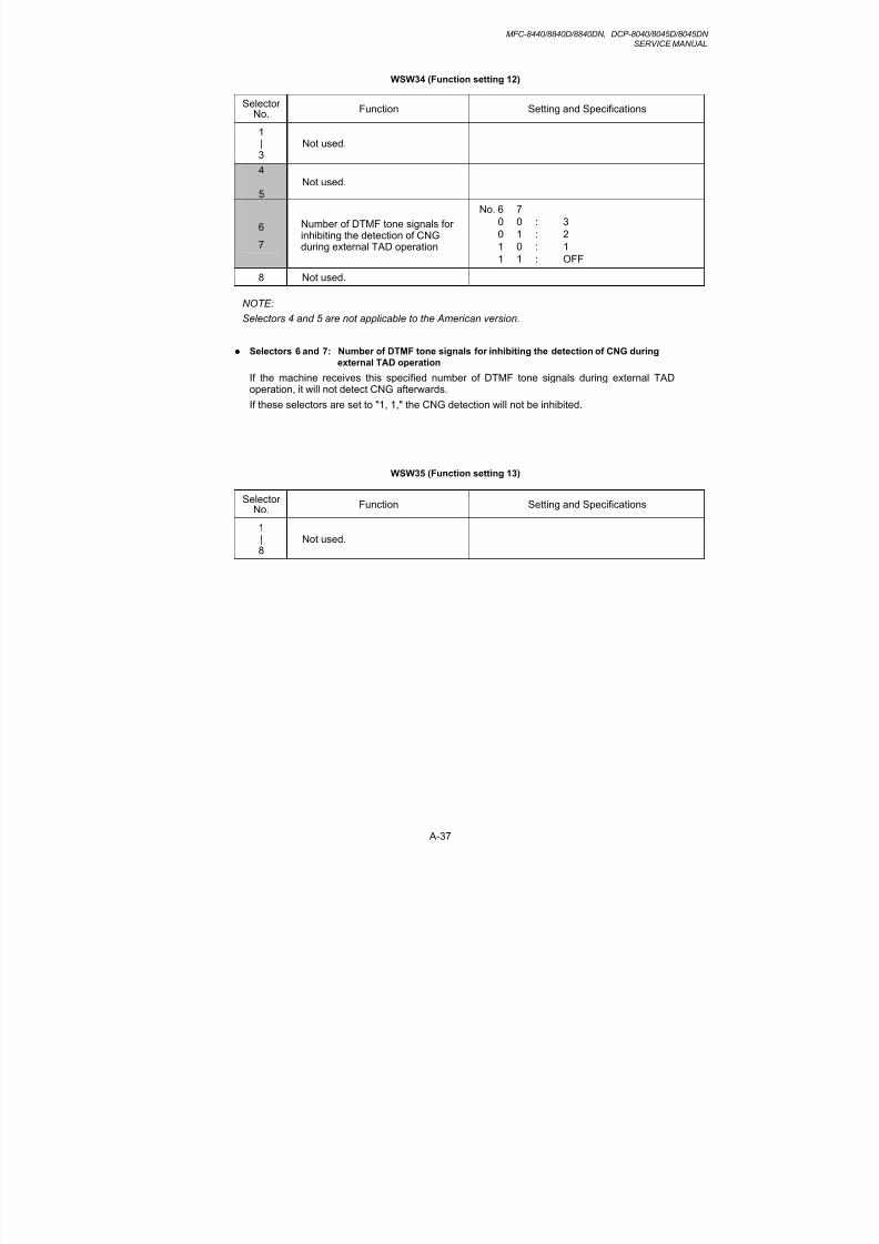
8/9/2019 DCP8040 DCP8045D MFC8440 MFC8840D MFC8840DN Manuales Técnicos.pdf
http://slidepdf.com/reader/full/dcp8040-dcp8045d-mfc8440-mfc8840d-mfc8840dn-manuales-tecnicospdf 330/361
MFC-8440/8840D/8840DN, DCP-8040/8045D/8045DNSERVICE MANUAL
A-37
WSW34 (Function setting 12)
SelectorNo.
Function Setting and Specifications
1|
3
Not used.
4
5Not used.
6
7
Number of DTMF tone signals forinhibiting the detection of CNGduring external TAD operation
No. 6 7
0 0 : 3
0 1 : 2
1 0 : 1
1 1 : OFF
8 Not used.
NOTE:Selectors 4 and 5 are not applicable to the American version.
Selectors 6 and 7: Number of DTMF tone signals for inhibiting the detection of CNG during
external TAD operation
If the machine receives this specified number of DTMF tone signals during external TADoperation, it will not detect CNG afterwards.
If these selectors are set to "1, 1," the CNG detection will not be inhibited.
WSW35 (Function setting 13)
SelectorNo.
Function Setting and Specifications
1|8
Not used.

8/9/2019 DCP8040 DCP8045D MFC8440 MFC8840D MFC8840DN Manuales Técnicos.pdf
http://slidepdf.com/reader/full/dcp8040-dcp8045d-mfc8440-mfc8840d-mfc8840dn-manuales-tecnicospdf 331/361
APPENDIX 3 FIRMWARE SWITCHS (WSW)
A-38
WSW36 (Function setting 14)
SelectorNo.
Function Setting and Specifications
1 ECP* mode 0: ON 1: OFF
2 Recovery from inactive PCinterface 0: Disabled 1: Enabled
3 PC power-off recognition time 0: Normal 1: Long
4 Not used.
5 Escape from phase C 0: Yes 1: No
6|8
Lower limit of frequency to beignored after detection of callingsignals (Ci)
No. 6 7 8
0 0 0 : 0 (Not ignored)
0 0 1 : 4 (448 Hz)
0 1 0 : 8 (244 Hz)
0 1 1 : 12 (162 Hz)
1 0 0 : 16 (122 Hz)
1 0 1 : 20 (97 Hz)1 1 0 : 24 (81 Hz)
1 1 1 : 28 (69 Hz)
*ECP (Enhanced Capabilities Port)
Selector 1: ECP mode
The ECP mode enhances the normal bidirectional communications between the machineand the connected PC for higher transmission speed.
Selector 2: Recovery from inactive PC interface
If the machine recognizes via the STB signal line that the connected PC is powered off, it willturn the PC interface outputs Low to protect the PC from hazards that could be caused by
weak electric current accidentally flown from the machine.This selector determines whether the machine should recover from the inactive PC interfaceto normal interfacing state upon receipt of data from the PC.
Selector 3: PC power-off recognition time
This selector sets the time length from when the machine detects the PC powered off until itrecognizes the detected state as power-off.
If selector 2 is set to "0," it is recommended that selector 3 be set to "1": otherwise, themachine may mistakenly detect PC powered off.
Selector 5: Escape from phase C
This selector determines whether or not the machine will escape from phase C when itdetects an RTC (Return to Control) in non-ECM mode or an RCP (Return to Control Partialpage) in ECM mode.
Selectors 6 through 8: Lower limit of frequency to be ignored after detection of calling signals
(Ci)
At the start of reception, if the machine detects the frequency of calling signals (Ci) specifiedby selectors 1 through 4 of WSW14, it will start the ringer sounding. When doing so, themachine may fail to detect the calling signals normally due to noises superimposed at thetime of reception. To prevent it, use selectors 6 through 8 of WSW36.
If the machine detects higher frequencies than the lower limit specified by these selectors, itwill regard them as noise and interpret that detecting state as being normal, allowing theringer to keep sounding (until the machine starts automatic reception of FAX data if in the
FAX mode, according to the preset number of ringers).

8/9/2019 DCP8040 DCP8045D MFC8440 MFC8840D MFC8840DN Manuales Técnicos.pdf
http://slidepdf.com/reader/full/dcp8040-dcp8045d-mfc8440-mfc8840d-mfc8840dn-manuales-tecnicospdf 332/361
MFC-8440/8840D/8840DN, DCP-8040/8045D/8045DNSERVICE MANUAL
A-39
WSW37 (Function setting 15)
SelectorNo.
Function Setting and Specifications
1Printout of the stored image data ofan unsent document onto the error
report
0: No 1: Yes
2
Erasure of the stored image data ofan unsent document at the time ofthe subsequent in-memorymessage transmission
0: No 1: Yes
3|8
Not used.
Selector 1: Printout of the stored image data of an unsent document onto an error report
This selector determines whether or not the 1st-page image data of a document will beprinted out onto the error report if the document image data stored in the temporary memorycannot be transmitted normally.
Selector 2: Erasure of the stored image data of an unsent document at the time of the
subsequent in-memory message transmission
If in-memory message transmission fails repeatedly when selector 1 is set to "1," thetemporary memory will be occupied with image data. Setting selector 2 to "1" willautomatically erase the stored 1st-page image data of an unsent document at the time of thesubsequent in-memory message transmission only when recording paper or toner runs out.

8/9/2019 DCP8040 DCP8045D MFC8440 MFC8840D MFC8840DN Manuales Técnicos.pdf
http://slidepdf.com/reader/full/dcp8040-dcp8045d-mfc8440-mfc8840d-mfc8840dn-manuales-tecnicospdf 333/361
APPENDIX 3 FIRMWARE SWITCHS (WSW)
A-40
WSW38 (Function setting 16)
SelectorNo.
Function Setting and Specifications
12 Setting of the equalizer
No. 1 2
0 X Automatic1 0 : Fixed to 4 points
1 1 : Fixed to 16 points
3 Sending level of guard tone atphase 2
0: Normal - 7 db 1: Normal
4 Stepping down the transmissionspeed at fallback each
0: 2400 bps 1: 4800 bps
5
6
Automatic control of modem's
EQM gain for proper transmissionspeed choice
No. 5 6
0 0 For higher transmission speedthan the current setting
0 1 : No change from the current
setting1 0 : For lower transmission speed
than the current setting
1 1 : For further lower transmissionthan the setting made by 1, 0
7 Redialing when a communicationserror occurs
0: ON 1: OFF
8 CED detection for CNG stoppage 0: ON 1: OFF
NOTE:
WSW38 takes effect only in the V. 34 mode.
Selectors 1 and 2: Setting of the equalizer
These selectors set the equalizer's training level to be applied if the machine fails to sendtraining due to weak line connection. If these selectors are set to "0, X," the modem willautomatically set the appropriate training level.
Selector 3: Sending level of guard tone at phase 2
This selector sets the sending level of guard tone for 1800 Hz to be sent at Phase 2 in the V.34 mode.
Selector 4: Stepping down the transmission speed at fallback each
This selector determines how much the modem steps down the transmission speed atfallback when called by the remote station. If this selector is set to "1," the modem may stepdown the transmission speed from 33600 bps to 28800 bps by one-time fallback.
Selectors 5 and 6: Automatic control of modem's EQM gain for proper transmission speed
choice
These selectors determine how the modem controls the EQM (Eye Quality Monitor) gain forproper choice of the transmission speed, which applies if the modem selects highertransmission speed than the possible speed so that it always repeats falling back.

8/9/2019 DCP8040 DCP8045D MFC8440 MFC8840D MFC8840DN Manuales Técnicos.pdf
http://slidepdf.com/reader/full/dcp8040-dcp8045d-mfc8440-mfc8840d-mfc8840dn-manuales-tecnicospdf 334/361
MFC-8440/8840D/8840DN, DCP-8040/8045D/8045DNSERVICE MANUAL
A-41
WSW39 (Function setting 17)
SelectorNo.
Function Setting and Specifications
1|4
First transmission speed choicefor fallback
No. 1 2 3 4No. 5 6 7 8
0 0 0 0 : 2400 bps
0 0 0 1 : 4800 bps
0 0 1 0 : 7200 bps
0 0 1 1 : 9600 bps
0 1 0 0 : 12000 bps
0 1 0 1 : 14400 bps
0 1 1 0 : 16800 bps
0 1 1 1 : 19200 bps
5|8
Last transmission speed choicefor fallback
1 0 0 0 : 21600 bps
1 0 0 1 : 24000 bps
1 0 1 0 : 26400 bps1 0 1 1 : 28800 bps
1 1 0 0 : 31200 bps
1 1 0 1 : 33600 bps
1 1 1 0 : 33600 bps
1 1 1 1 : 33600 bps
NOTE:
WSW39 takes effect only in V. 34 mode. For the transmission speed setting in other modes,refer to WSW19.
Selectors 1 through 8: First and last choices of transmission speed for fallback
These selectors are used to set the modem speed range. With the first transmission speedchoice specified by selectors 1 through 4, the machine attempts to establish the transmissionlink via the modem. If the establishment fails, the machine automatically steps down to thenext highest speed and attempts to establish the transmission link again. The machinerepeats this sequence while stepping down the transmission speed to the last choicespecified by selectors 5 through 8.
If the modem always falls back to a low transmission speed (e.g., 24,000 bps), set the firsttransmission speed choice to the lower one (e.g., modify it from 31,200 bps to 26,400 bps) inorder to deactivate the high-speed modem function and reduce the training time for shortertransmission time.
WSW39 will be limited by selectors 3 through 8 of WSW40.

8/9/2019 DCP8040 DCP8045D MFC8440 MFC8840D MFC8840DN Manuales Técnicos.pdf
http://slidepdf.com/reader/full/dcp8040-dcp8045d-mfc8440-mfc8840d-mfc8840dn-manuales-tecnicospdf 335/361
APPENDIX 3 FIRMWARE SWITCHS (WSW)
A-42
WSW40 (Function setting 18)
SelectorNo.
Function Setting and Specifications
1 Not used.
2 Not used.
3|8
Masking of symbol rate(s)
Not masking Masking
No. 3 0 1 3429 symbols/secNo. 4 0 1 3200 symbols/secNo. 5 0 1 3000 symbols/secNo. 6 0 1 2800 symbols/secNo. 7 - - Not used.No. 8 0 1 2400 symbols/sec
NOTE:
• WSW40 takes effect only in the V. 34 mode.
• Selector 2 is applicable only to models equipped with a flat-bed scanner.
Selectors 3 and 8: Masking of symbol rate(s)
These selectors allow you to limit the transmission speed range in the V. 34 mode bymasking the desired symbol rate(s). Transmission speeds assigned to the symbol rates arelisted below. The setting made by these selectors will limit the setting made by selectors 1through 4 of WSW39.
If selector 3 is set to "1" to mask the 3429 symbols/second when the first transmission speedchoice is 33600 bps (specified by selectors 1 through 4 of WSW39), for example, theallowable maximum transmission speed will be limited to 31200 bps. If selector 8 is set to "1"to mask the 2400 symbols/second when the first transmission speed choice is 33600 bps,then the allowable maximum transmission speed remains 33600 bps.
If selector 8 is set to "1" to mask the 2400 symbols/second when the first transmission speedchoice is 21600 bps (specified by selectors 1 through 4 of WSW39), the allowable maximumtransmission speed remains 21600 bps but the minimum transmission speed will be limitedto 4800 bps.
Symbol rate Transmission speed(bps)
Symbol rate Transmission speed(bps)
Symbol rate Transmission speed(bps)
2400 2400 3000 4800 3429 4800
4800 7200 7200
7200 9600 9600
9600 12000 12000
12000 14400 14400
14400 16800 16800
16800 19200 19200
19200 21600 21600
21600 24000 24000
2800 4800 26400 28800
7200 28800 31200
9600 3200 4800 33600
12000 7200
14400 9600
16800 12000
19200 14400
21600 16800
24000 19200
26400 21600
24000
26400
2880031200

8/9/2019 DCP8040 DCP8045D MFC8440 MFC8840D MFC8840DN Manuales Técnicos.pdf
http://slidepdf.com/reader/full/dcp8040-dcp8045d-mfc8440-mfc8840d-mfc8840dn-manuales-tecnicospdf 336/361
MFC-8440/8840D/8840DN, DCP-8040/8045D/8045DNSERVICE MANUAL
A-43
WSW41 (Function setting 19)
SelectorNo.
Function Setting and Specifications
1|3
ON-duration of the fluorescent lampbuilt in the CCD unit
No. 1 2 3
0 0 0 : 16 hours0 0 1 : 24 hours
0 1 0 : 12 hours
0 1 1 : 8 hours
1 0 0 : 4 hours
1 0 1 : 2 hours
1 1 0 : 10 minutes
1 1 1 : 0 minute
4 Broadcast report via e-mail 0: ON 1: OFF
5|8
Modem attenuator
No. 5 6 7 8
0 0 0 0 : -10 dBm0 0 0 1 : -11 dBm
0 0 1 0 : -12 dBm
0 0 1 1 : -13 dBm
0 1 0 0 : -14 dBm
| |
1 1 1 1 : -25 dBm
NOTE:
• WSW41 takes effect only in the V. 34 mode.
• Selectors 1 through 3 are applicable only to models equipped with a flat-bed scanner.
Selectors 1 through 3: ON-duration of the fluorescent lamp built in the CCD unit
If the scanning operation is started when the fluorescent lamp is off, then the lamp will comeon for scanning. These selectors determine how long the lamp will stay ON after scanning.
If these selectors are set to "1, 1, 1," the fluorescent lamp will go off after the scanningsequence.
Selectors 5 through 8: Modem attenuator
These selectors are used to adjust the transmitting level of the modem when the receptionlevel at the remote station is improper due to line loss. This function applies to super G3
protocol signals.

8/9/2019 DCP8040 DCP8045D MFC8440 MFC8840D MFC8840DN Manuales Técnicos.pdf
http://slidepdf.com/reader/full/dcp8040-dcp8045d-mfc8440-mfc8840d-mfc8840dn-manuales-tecnicospdf 337/361
APPENDIX 3 FIRMWARE SWITCHS (WSW)
A-44
WSW42 (Function setting 20)
SelectorNo.
Function Setting and Specifications
1 Incoming mail server POP*1 0: OFF 1: ON
2 Incoming mail server SMTP*2
0: OFF 1: ON
3 Internet-FAX forward function 0: OFF 1: ON
4 JBIG*3 coding system 0: Disabled 1: Enabled
*1
POP: Post Office Protocol*
2SMTP: Simple Mail Transfer
Protocol*
3JBIG: Joint Bi-level Image
Group
NOTE:
• Selectors 1 through 3 are applicable to those models equipped with LAN interface.
Selector 3: Internet-FAX forward function
If this selector is set to "ON," the machine may forward a FAX message received throughInternet to other remote G3 facsimile equipment.

8/9/2019 DCP8040 DCP8045D MFC8440 MFC8840D MFC8840DN Manuales Técnicos.pdf
http://slidepdf.com/reader/full/dcp8040-dcp8045d-mfc8440-mfc8840d-mfc8840dn-manuales-tecnicospdf 338/361
MFC-8440/8840D/8840DN, DCP-8040/8045D/8045DNSERVICE MANUAL
A-45
WSW43 (Function setting 21)
SelectorNo.
Function Setting and Specifications
1 Addition of a header (station ID) toFAX images to be sent to PCs
having e-mail addresses
0: Yes 1: No
2
3
Wait time for PCFax reception(Class 2) and FPTS commandtransmission
No. 2 3
0 0 : 50 ms
0 1 : 100 ms
1 0 : 150 ms
1 1 : 0 ms
4
5
Detection time of 2100 Hz CED or ANSam
No. 4 5
0 0 : 200 ms
0 1 : 300 ms
1 0 : 400 ms
1 1 : 500 ms
6 Not used.
7 Automatic start of remotemaintenance
0: No 1: Yes
8 JPEG coding 0: Disabled 1: Enabled
NOTE:
Selector 1 is applicable to those models equipped with LAN interface.
Selector 8: JPEG coding
Setting this selector to “0” disables the equipment from sending/receiving JPEG color imagesand from receiving JPEG monochrome images.

8/9/2019 DCP8040 DCP8045D MFC8440 MFC8840D MFC8840DN Manuales Técnicos.pdf
http://slidepdf.com/reader/full/dcp8040-dcp8045d-mfc8440-mfc8840d-mfc8840dn-manuales-tecnicospdf 339/361
APPENDIX 3 FIRMWARE SWITCHS (WSW)
A-46
WSW44 (Speeding up scanning-1)
SelectorNo.
Function Setting and Specifications
1|
5
Not used.
6|8
Effective time length of the white levelcompensation data obtainedbeforehand
No. 6 7 8
0 0 0 : Obtained compensation dataineffective
0 0 1 : 1 min.
0 1 0 : 3 min.
0 1 1 : 5 min.
1 0 0 : 10 min.
1 0 1 : 15 min.
1 1 0 : 20 min.
1 1 1 : 30 min.
NOTE:
WSW44 is applicable only to models equipped with a flat-bed scanner.
Selectors 6 through 8: Effective time length of the white level compensation data obtained
beforehand
If you set documents in the ADF and the document front sensor detects them or if you openthe document tray ASSY and the document tray open sensor detects the open state, then thecontroller will make correction of the reference voltage to be applied to white levelcompensation for document scanning before the Copy button is pressed.
These selectors determine how long compensation data obtained beforehand will keep
effective.

8/9/2019 DCP8040 DCP8045D MFC8440 MFC8840D MFC8840DN Manuales Técnicos.pdf
http://slidepdf.com/reader/full/dcp8040-dcp8045d-mfc8440-mfc8840d-mfc8840dn-manuales-tecnicospdf 340/361
MFC-8440/8840D/8840DN, DCP-8040/8045D/8045DNSERVICE MANUAL
A-47
WSW45 (Speeding up scanning-2)
SelectorNo.
Function Setting and Specifications
1|3
Delay time from when documentsare set until the ADF starts drawingthem in
No. 1 2 3
0 0 0 : No automatic drawing-in
0 0 1 : 1 sec.
0 1 0 : 2 sec.
0 1 1 : 3 sec.
1 0 0 : 4 sec.
1 0 1 : 5 sec.
1 1 0 : 6 sec.
1 1 1 : 7 sec.
4
|6
Periodical correction intervals of the
reference voltage to be applied towhite level compensation fordocument scanning, during standby
No. 4 5 6
0 0 0 : No correction of referencevoltage during standby
0 0 1 : 10 sec.
0 1 0 : 30 sec.
0 1 1 : 1 min.
1 0 0 : 3 min.
1 0 1 : 5 min.
1 1 0 : 10 min.
1 1 1 : 30 min.
7 Standby position of the CCD unit0: CCD lock position 1: Location of
(Home position) the white-levelreference film
8 Not used.
NOTE:
WSW45 is applicable only to models equipped with a flat-bed scanner.
Selectors 1 through 3: Delay time from when documents are set until the ADF starts drawing
them in
These selectors determine how long the ADF will delay automatic drawing-in of documents(to the scanning standby position) after you set them in the ADF, as well as determiningwhether or not the ADF automatically draws in documents.
Selectors 4 through 6: Periodical correction intervals of the reference voltage applied to white
level compensation for document scanning, during standby
These selectors set the correction intervals (in seconds) of the reference voltage to beapplied to white level compensation for document scanning during standby, as well asdetermining whether or not the controller makes the reference voltage correction duringstandby. (Conventionally, the correction has been made immediately before the start ofactual scanning)
This function takes effect in copying. Making the correction during standby may shorten thepreparation time for copying.
NOTE:
Do not access these selectors.
Selector 7: Standby position of the CCD unit
This selector determines whether the standby position of the CCD unit should be the CCDlock position (home position) or the location of the white-level reference film (attached to theinside of the scanner top cover). If the location of the reference film is selected, the CCD unit
will not return to the lock position so as to shorten the travel time, decreasing the preparationtime for copying.

8/9/2019 DCP8040 DCP8045D MFC8440 MFC8840D MFC8840DN Manuales Técnicos.pdf
http://slidepdf.com/reader/full/dcp8040-dcp8045d-mfc8440-mfc8840d-mfc8840dn-manuales-tecnicospdf 341/361
APPENDIX 3 FIRMWARE SWITCHS (WSW)
A-48
WSW46 (Monitor of PC ON/OFF state)
SelectorNo.
Function Setting and Specifications
12
Monitoring the PC ON/OFF state
No. 1 2
0 0 : Disabled
0 1 : Monitor SELECT IN
1 0 : Monitor STROBE
1 1 : Monitor both SELECT IN andSTROBE
3Parallel port output pins kept at highlevel
0: Enabled 1: Disabled
4Scanned garbage correctionprocessing
0: ON 1: OFF
5|8
Not used.
NOTE:
• Selector 3 is applicable only to models equipped with a parallel interface.
• Selectors 6 through 8 are applicable only to models equipped with a flat-bed scanner.
Selectors 1 and 2: Monitoring the PC ON/OFF state
For the related functions, refer to WSW36, selectors 2 and 3.
Selectors 3: Parallel port output pins kept at high level
Setting this selector to “0” will keep all parallel output pins of the facsimile equipment at highlevel. Use this setting if Resource Manager (bundled with MFC models) installed to WindowsNT running on the connected PC fails to monitor the power ON/OFF state of the facsimileequipment.
WSW47 (Function setting 22)
SelectorNo.
Function Setting and Specifications
1|
7
Not used.
8 Switching of USB High/Full Speed0: Auto (Automatic switching)
1: Full speed is set.

8/9/2019 DCP8040 DCP8045D MFC8440 MFC8840D MFC8840DN Manuales Técnicos.pdf
http://slidepdf.com/reader/full/dcp8040-dcp8045d-mfc8440-mfc8840d-mfc8840dn-manuales-tecnicospdf 342/361

8/9/2019 DCP8040 DCP8045D MFC8440 MFC8840D MFC8840DN Manuales Técnicos.pdf
http://slidepdf.com/reader/full/dcp8040-dcp8045d-mfc8440-mfc8840d-mfc8840dn-manuales-tecnicospdf 343/361
APPENDIX 4 CIRCUIT DIAGRAMS
A-50
Appendix 4.1 Main PCB Circuit Diagram (1/7)

8/9/2019 DCP8040 DCP8045D MFC8440 MFC8840D MFC8840DN Manuales Técnicos.pdf
http://slidepdf.com/reader/full/dcp8040-dcp8045d-mfc8440-mfc8840d-mfc8840dn-manuales-tecnicospdf 344/361
A-51
Appendix 4.2 Main PCB Circuit Diagram (2/7)
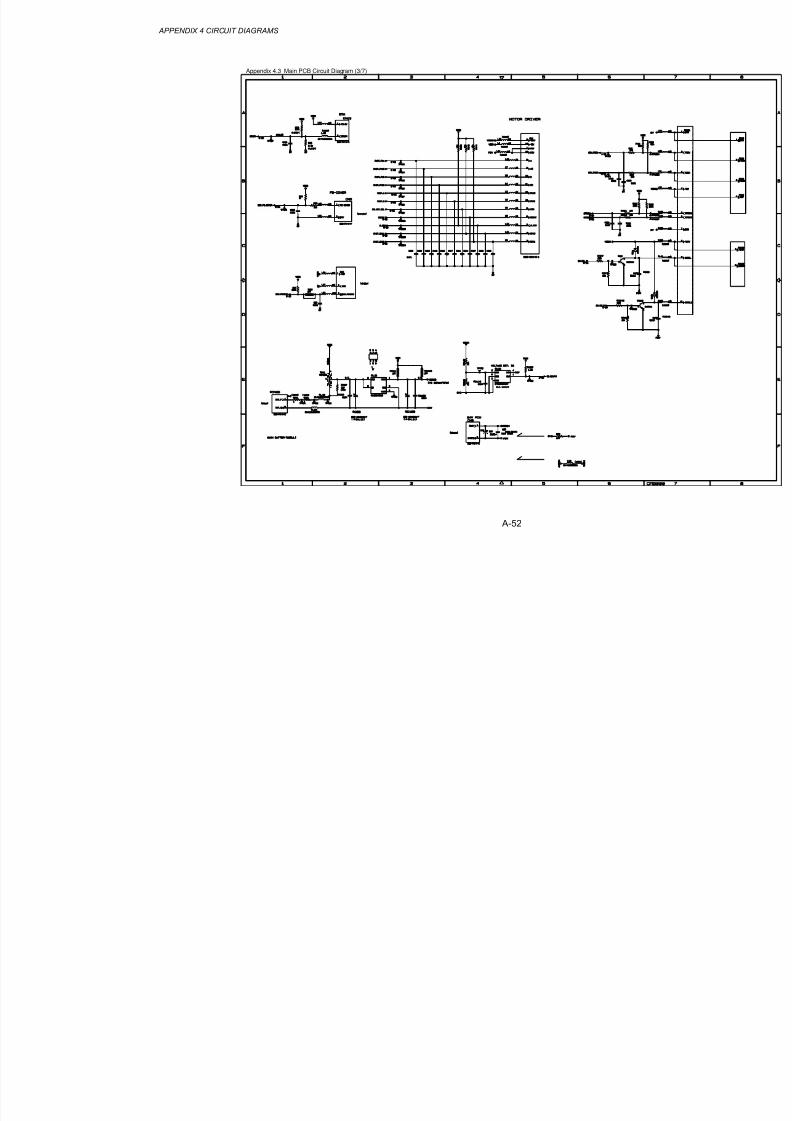
8/9/2019 DCP8040 DCP8045D MFC8440 MFC8840D MFC8840DN Manuales Técnicos.pdf
http://slidepdf.com/reader/full/dcp8040-dcp8045d-mfc8440-mfc8840d-mfc8840dn-manuales-tecnicospdf 345/361
APPENDIX 4 CIRCUIT DIAGRAMS
A-52
Appendix 4.3 Main PCB Circuit Diagram (3/7)

8/9/2019 DCP8040 DCP8045D MFC8440 MFC8840D MFC8840DN Manuales Técnicos.pdf
http://slidepdf.com/reader/full/dcp8040-dcp8045d-mfc8440-mfc8840d-mfc8840dn-manuales-tecnicospdf 346/361
A-53
Appendix 4.4 Main PCB Circuit Diagram (4/7)

8/9/2019 DCP8040 DCP8045D MFC8440 MFC8840D MFC8840DN Manuales Técnicos.pdf
http://slidepdf.com/reader/full/dcp8040-dcp8045d-mfc8440-mfc8840d-mfc8840dn-manuales-tecnicospdf 347/361
APPENDIX 4 CIRCUIT DIAGRAMS
A-54
Appendix 4.5 Main PCB Circuit Diagram (5/7)

8/9/2019 DCP8040 DCP8045D MFC8440 MFC8840D MFC8840DN Manuales Técnicos.pdf
http://slidepdf.com/reader/full/dcp8040-dcp8045d-mfc8440-mfc8840d-mfc8840dn-manuales-tecnicospdf 348/361
A-55
Appendix 4.6 Main PCB Circuit Diagram (6/7)

8/9/2019 DCP8040 DCP8045D MFC8440 MFC8840D MFC8840DN Manuales Técnicos.pdf
http://slidepdf.com/reader/full/dcp8040-dcp8045d-mfc8440-mfc8840d-mfc8840dn-manuales-tecnicospdf 349/361
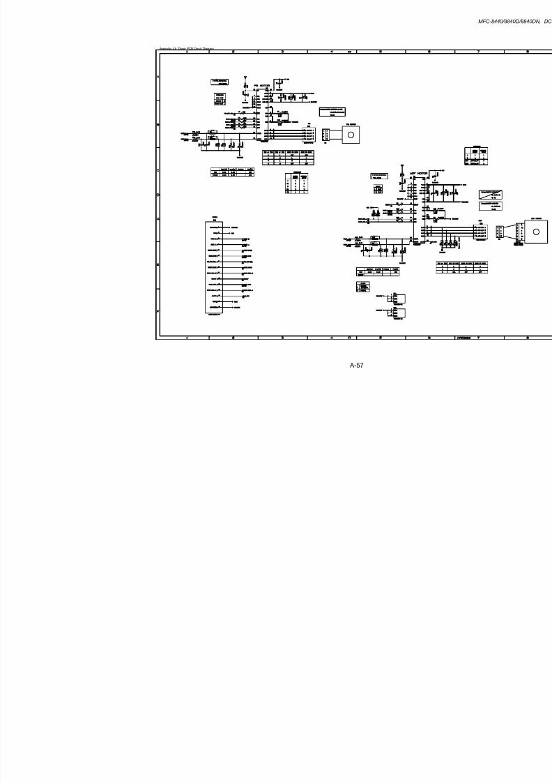
8/9/2019 DCP8040 DCP8045D MFC8440 MFC8840D MFC8840DN Manuales Técnicos.pdf
http://slidepdf.com/reader/full/dcp8040-dcp8045d-mfc8440-mfc8840d-mfc8840dn-manuales-tecnicospdf 350/361
A-57
Appendix 4.8 Driver PCB Circuit Diagram
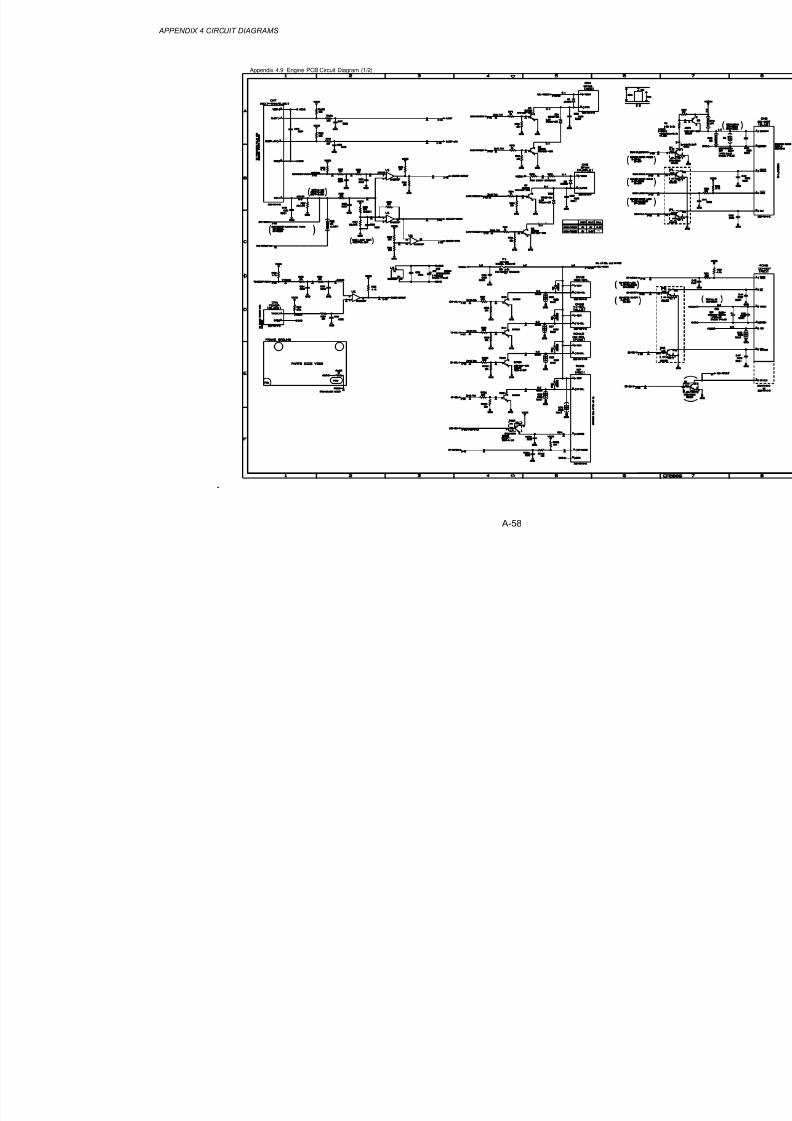
8/9/2019 DCP8040 DCP8045D MFC8440 MFC8840D MFC8840DN Manuales Técnicos.pdf
http://slidepdf.com/reader/full/dcp8040-dcp8045d-mfc8440-mfc8840d-mfc8840dn-manuales-tecnicospdf 351/361
APPENDIX 4 CIRCUIT DIAGRAMS
A-58
Appendix 4.9 Engine PCB Circuit Diagram (1/2)

8/9/2019 DCP8040 DCP8045D MFC8440 MFC8840D MFC8840DN Manuales Técnicos.pdf
http://slidepdf.com/reader/full/dcp8040-dcp8045d-mfc8440-mfc8840d-mfc8840dn-manuales-tecnicospdf 352/361
A-59
Appendix 4.10 Engine PCB Circuit Diagram (2/2)

8/9/2019 DCP8040 DCP8045D MFC8440 MFC8840D MFC8840DN Manuales Técnicos.pdf
http://slidepdf.com/reader/full/dcp8040-dcp8045d-mfc8440-mfc8840d-mfc8840dn-manuales-tecnicospdf 353/361
APPENDIX 4 CIRCUIT DIAGRAMS
A-60
Appendix 4.11 NCU PCB Circuit Diagram (U.S.A.)

8/9/2019 DCP8040 DCP8045D MFC8440 MFC8840D MFC8840DN Manuales Técnicos.pdf
http://slidepdf.com/reader/full/dcp8040-dcp8045d-mfc8440-mfc8840d-mfc8840dn-manuales-tecnicospdf 354/361
A-61
Appendix 4.12 NCU PCB Circuit Diagram (Europe)

8/9/2019 DCP8040 DCP8045D MFC8440 MFC8840D MFC8840DN Manuales Técnicos.pdf
http://slidepdf.com/reader/full/dcp8040-dcp8045d-mfc8440-mfc8840d-mfc8840dn-manuales-tecnicospdf 355/361
APPENDIX 4 CIRCUIT DIAGRAMS
A-62
Appendix 4.13 NCU PCB Circuit Diagram (Asia)

8/9/2019 DCP8040 DCP8045D MFC8440 MFC8840D MFC8840DN Manuales Técnicos.pdf
http://slidepdf.com/reader/full/dcp8040-dcp8045d-mfc8440-mfc8840d-mfc8840dn-manuales-tecnicospdf 356/361
A-63
Appendix 4.14 NCU PCB Circuit Diagram (Oceania)

8/9/2019 DCP8040 DCP8045D MFC8440 MFC8840D MFC8840DN Manuales Técnicos.pdf
http://slidepdf.com/reader/full/dcp8040-dcp8045d-mfc8440-mfc8840d-mfc8840dn-manuales-tecnicospdf 357/361
APPENDIX 4 CIRCUIT DIAGRAMS
A-64
Appendix 4.15 Control Panel PCB Circuit Diagram

8/9/2019 DCP8040 DCP8045D MFC8440 MFC8840D MFC8840DN Manuales Técnicos.pdf
http://slidepdf.com/reader/full/dcp8040-dcp8045d-mfc8440-mfc8840d-mfc8840dn-manuales-tecnicospdf 358/361
A-65
Appendix 4.16 Low-voltage Power Supply PCB Circuit Diagram (200V)

8/9/2019 DCP8040 DCP8045D MFC8440 MFC8840D MFC8840DN Manuales Técnicos.pdf
http://slidepdf.com/reader/full/dcp8040-dcp8045d-mfc8440-mfc8840d-mfc8840dn-manuales-tecnicospdf 359/361
APPENDIX 4 CIRCUIT DIAGRAMS
A-66
Appendix 4.17 Low-voltage Power Supply PCB Circuit Diagram (100V)

8/9/2019 DCP8040 DCP8045D MFC8440 MFC8840D MFC8840DN Manuales Técnicos.pdf
http://slidepdf.com/reader/full/dcp8040-dcp8045d-mfc8440-mfc8840d-mfc8840dn-manuales-tecnicospdf 360/361
A-67
Appendix 4.18 High-voltage Power Supply PCB Circuit Diagram (200V)

8/9/2019 DCP8040 DCP8045D MFC8440 MFC8840D MFC8840DN Manuales Técnicos.pdf
http://slidepdf.com/reader/full/dcp8040-dcp8045d-mfc8440-mfc8840d-mfc8840dn-manuales-tecnicospdf 361/361
APPENDIX 4 CIRCUIT DIAGRAMS
A-68
Appendix 4.19 High-voltage Power Supply PCB Circuit Diagram (100V)