Desarrollo de sensores basados en Fibra Óptica para la ......basados en Fibra Óptica para la...
27
Desarrollo de sensores basados en Fibra Óptica para la Medición de Variables Eléctricas para Sistemas de Potencia Laboratorio Alto Voltaje Laboratorio Fotónica y Optoelectrónica Universidad Nacional de Colombia - sede Medellín Laboratory of Smart Composites University of Wisconsin-Milwaukee Presentadores: Esteban Jiménez Mejía Clara Rojo Ceballos
Transcript of Desarrollo de sensores basados en Fibra Óptica para la ......basados en Fibra Óptica para la...

Desarrollo de sensores basados en Fibra Óptica para
la Medición de Variables Eléctricas para Sistemas de
PotenciaLaboratorio Alto Voltaje
Laboratorio Fotónica y Optoelectrónica
Universidad Nacional de Colombia - sede Medellín
Laboratory of Smart Composites
University of Wisconsin-Milwaukee
Presentadores: Esteban Jiménez Mejía
Clara Rojo Ceballos

2
Electrical variables in high voltagepower-lines have been measuredtraditionally by CTs and PTs.
CTs and PTs:• have shown to be a high
reliable technology• Presents long-term stability• Are fully incorporated in
the power delivery marketTaken from: http://www.lightningprotection.co.nz/substation-transformers/
Current Transformers CTs Potential Transformers PTs
Scope

3
• Elaborative selection process.• Continuous maintenance to guarantee its proper
functioning.• In CTs secondary openings could lead to dangerous
high-voltages and explosions.• Magnetic core saturation• Reduced frequency bandwidth operation.
CTs and PTs require

4
OPTs and OCTs
Optical-based devices for measuring electricalvariables in high voltage power systems offer severaladvantages respect to conventional systems:• Inherent insulation level and high dielectric
strength• Electromagnetic noise immunity• No magnetic cores and saturation problems• Wide Frequency Bandwidth response• Reduced size and lighter weight

5
Two main type of these sensors can beidentified depending on its constitutiveelements:
• Hybrid Sensors• All-optical-based sensors
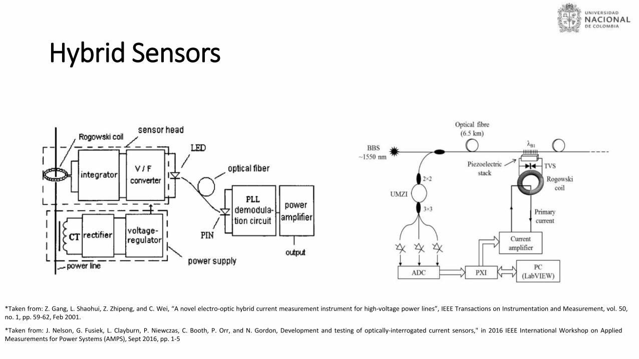
Hybrid Sensors
*Taken from: Z. Gang, L. Shaohui, Z. Zhipeng, and C. Wei, “A novel electro-optic hybrid current measurement instrument for high-voltage power lines”, IEEE Transactions on Instrumentation and Measurement, vol. 50,no. 1, pp. 59-62, Feb 2001.
*Taken from: J. Nelson, G. Fusiek, L. Clayburn, P. Niewczas, C. Booth, P. Orr, and N. Gordon, Development and testing of optically-interrogated current sensors," in 2016 IEEE International Workshop on AppliedMeasurements for Power Systems (AMPS), Sept 2016, pp. 1-5

7
Main disadvantages of hybrid sensors is that they inherit all measurement limitations such as: • Saturation effects • Poor frequency response• Active electronic for processing and powering are
required
Hybrid Sensors

All-optical-based sensors
*Taken from: M. Kanoe, G. Takahashi, T. Sato, M. Higaki, E. Mori, and K. Okumura, “Optical voltage and current measuring system for electric power systems”, IEEE Transactions on Power Delivery, vol. 1,no. 1, pp. 91-97, Jan 1986
*Taken from: R. Wang, S. Xu, W. Li, and X. Wang, "Optical fiber current sensor research: review and outlook", Optical and Quantum Electronics, vol. 48, no. 9, p. 442, 2016
*Taken from: M. H. Samimi, A. A. S. Akmal, and H. Mohseni, "Optical current transducers and error sources in them: A review", IEEE Sensors Journal, vol. 15, no. 9, pp. 4721-4728, Sept 2015.

9
Main disadvantages of All-fiber Optical sensors: • Intrinsic birefringence effects could lead to great
amount of errors.• Highly precise manufacturing processes are required.• Strong dependence to vibration shocks and
temperature drifts.
All Fiber Optical Sensors

10
This approach deals with the proposal, analyticalbackground and practical implementation of two fiberoptic based sensors that could be used for measuringelectrical variables in high voltage systems:
• the physical and mathematical formulation for each ofthe sensing principles that were tackled in theproposition:• MagnetostrictionMagnetic field/Current• Piezoelectricity Electric field/Voltage

11
Magnetic field sensing principle
The mechanical strain from magnetostriction in the composite can betransferred to a Fiber Bragg Grating (FBG) for enabling strain measurementthrough optical devices.
after the interaction with magnetostriction inside the body
Initially non-chirped FBG
Chirped FBG due to magnetostriction interaction
central wavelength shifting with constant linewidth (constant reflected optical power)
central wavelength shifting and spectrum broadening (variable reflected optical power)
Magnetic field
12
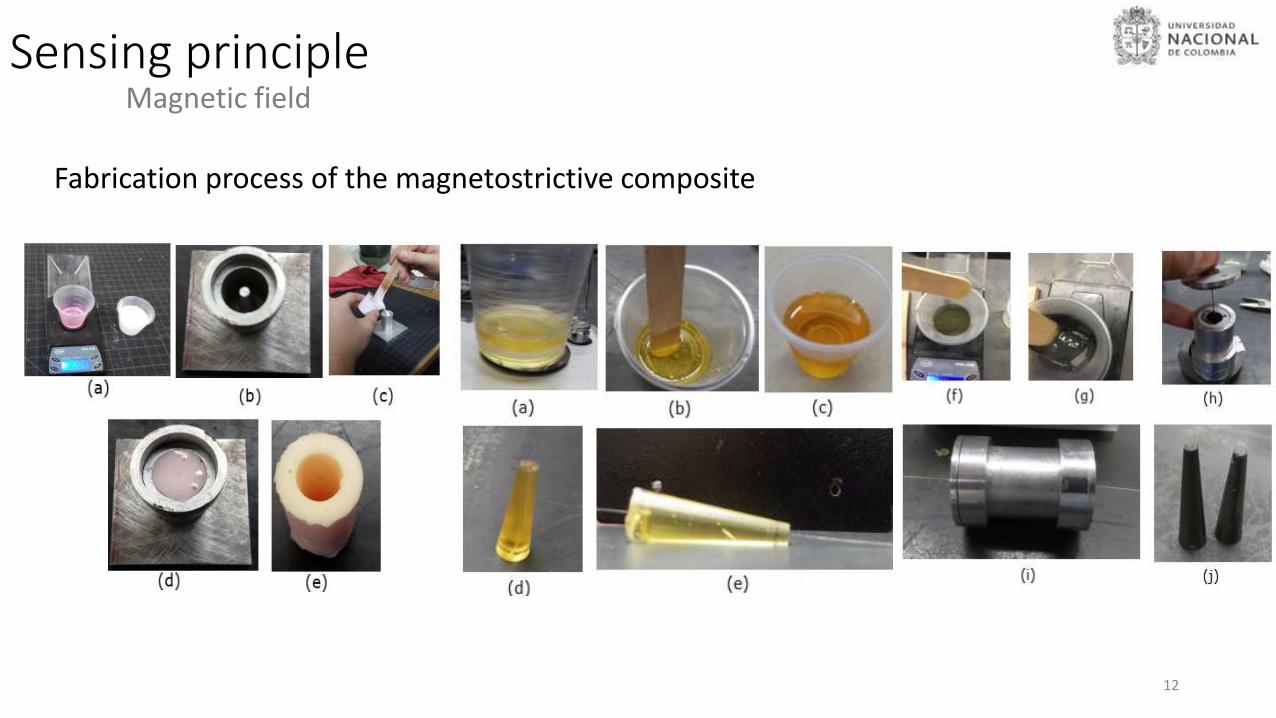
Sensing principleMagnetic field
Fabrication process of the magnetostrictive composite

13
Sensing principle and Optical detectionMagnetic field – Experimental Results

14
Sensing principle and Optical detectionMagnetic field – Experimental Results
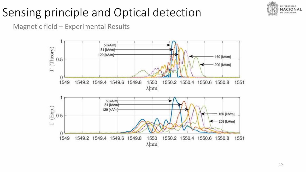
15
Sensing principle and Optical detectionMagnetic field – Experimental Results

16
Sensing principle and Optical detectionMagnetic field – Experimental Results
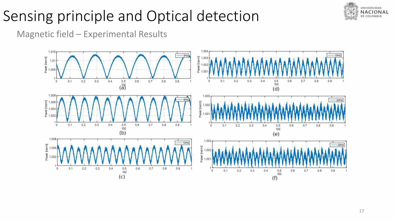
17
Sensing principle and Optical detectionMagnetic field – Experimental Results

18
Sensing principle and Optical detectionVoltage measurement

19
Sensing principle and Optical detectionVoltage measurement
(a) Configuration A: Upper layer is excited. (b) Configuration B: Bottom layer is excited.

20
Sensing principle and Optical detectionVoltage measurement

21
Sensing principle and Optical detectionVoltage measurement

22
Sensing principle and Optical detectionHigh voltage measurement
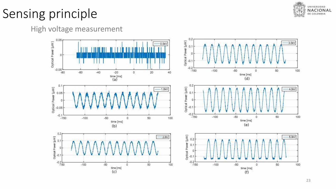
23
Sensing principleHigh voltage measurement

24
Sensing principleHigh voltage measurement

Conclusions• A suitable sensor arrangement for measuring electricalvariables by using magnetostrictive and piezoelectricmaterials coupled to optical fibers was presented andimplemented in practice.
• The geometrical effects upon the demagnetization field andits consequences upon the transferred strain to theembedded fiber grating were successfully modeled andexperimentally evidenced.
25

Future work
• Fabrication process showed to have a strong influencein the overall performance of the implementedsensors. A systematic standardization process isrequired to guarantee initial conditions andrepeatability.
• Implementation of the voltage sensor with out theinitial capacitive divisor (it will be more suitable forhigher voltage systems)
26

Preguntas?