diseño de marcos trabe columna
12
Lecture 15 – Page 1 of 12 Lecture 15 – Columns (cont.) In the previous lecture, we talked about columns having small eccentricity (i.e., small applied moment) . While this may be the case fo r interior columns with offsetting moments, the majority of concrete columns do experience applied moments. Concrete framed buildings typically have columns that are poured monolithically with beams and slabs, thus creating a statically-indetermin ate frame such as the one shown below: The analysis of such a frame is usually quite complex and requires computer softwar e such as STAAD or approximate analysis methods such as the Portal Method and others discussed in Structural Theory.
-
Upload
jorge-galvan-godoy -
Category
Documents
-
view
222 -
download
0
Transcript of diseño de marcos trabe columna

7/28/2019 diseño de marcos trabe columna
http://slidepdf.com/reader/full/diseno-de-marcos-trabe-columna 1/12
Lecture 15 – Page 1 of 12
Lecture 15 – Columns (cont.)
In the previous lecture, we talked about columns having small eccentricity (i.e.,small applied moment). While this may be the case for interior columns withoffsetting moments, the majority of concrete columns do experience appliedmoments.
Concrete framed buildings typically have columns that are poured monolithicallywith beams and slabs, thus creating a statically-indeterminate frame such as the
one shown below:
The analysis of such a frame is usually quite complex and requires computer software such as STAAD or approximate analysis methods such as the PortalMethod and others discussed in Structural Theory.

7/28/2019 diseño de marcos trabe columna
http://slidepdf.com/reader/full/diseno-de-marcos-trabe-columna 2/12
Lecture 15 – Page 2 of 12
The compression capacity of a reinforced column is reduced by the bendingstresses on the column and vice-versa. A graph of the axial load capacity of a
column vs. the moment capacity of a typical column is shown below (fromLecture 14):
Determining points along the curve is quite laborious and typically not done usinghand calculations. Instead, computer programs or design guides are used toperform column analysis and design.
Below are some “Column Interaction Diagrams” that are used for column
analysis and design.
A x
i a l c o m p r e s s i o n c a p a c i t y
Bending moment capacity
Pure compression (no
applied moment)
Pure bending (no
applied axial load)

7/28/2019 diseño de marcos trabe columna
http://slidepdf.com/reader/full/diseno-de-marcos-trabe-columna 3/12
Lecture 15 – Page 3 of 12
Rectangular TIED Column Interaction Diagrams
R4-60.75
“R” = Rectangular cross-section“4” = f’c = 4 KSI
“60” = Grade 60 vertical bars
“75” = γ

7/28/2019 diseño de marcos trabe columna
http://slidepdf.com/reader/full/diseno-de-marcos-trabe-columna 4/12
Lecture 15 – Page 4 of 12
Circular SPIRAL Column Interaction Diagrams
7/28/2019 diseño de marcos trabe columna
http://slidepdf.com/reader/full/diseno-de-marcos-trabe-columna 5/12
Lecture 15 – Page 5 of 12
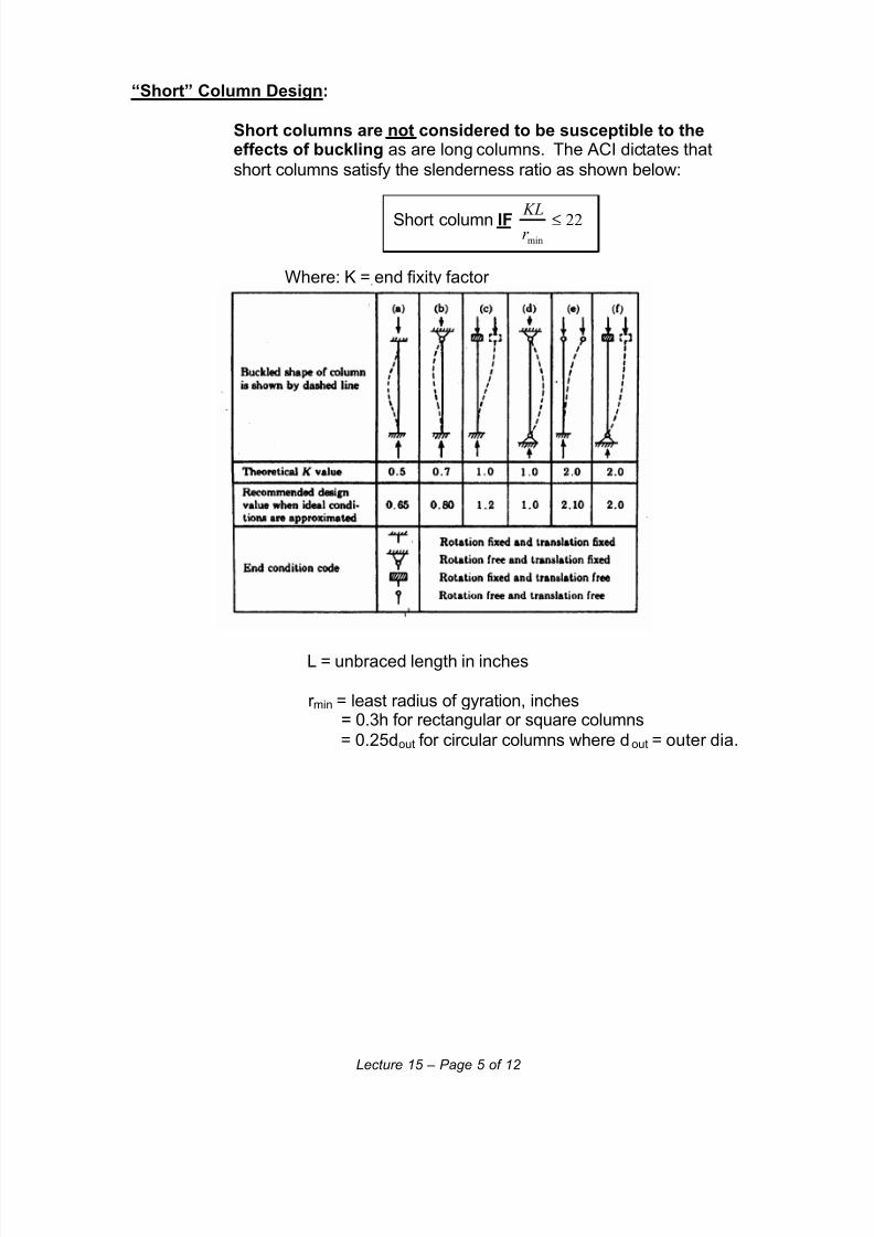
“Short” Column Design:
Short columns are not considered to be susceptible to theeffects of buckling as are long columns. The ACI dictates that
short columns satisfy the slenderness ratio as shown below:
Short column IF 22min
≤r KL
Where: K = end fixity factor
L = unbraced length in inches
r min = least radius of gyration, inches= 0.3h for rectangular or square columns
= 0.25dout for circular columns where dout = outer dia.

7/28/2019 diseño de marcos trabe columna
http://slidepdf.com/reader/full/diseno-de-marcos-trabe-columna 6/12
Lecture 15 – Page 6 of 12
ExampleGIVEN: A 20” x 20” square interior tied column is shown below. Use concrete f’c
= 4000 PSI and 8 - #8 grade 60 vertical bars and #3 ties. Concrete cover = 1½”. All loads are factored and includes beam weight. Assume the beams are “fixed”to the columns.
REQUIRED:
1) Determine the applied factored axial load, Pu on the middle column. Besure to add column weight. Assume the loads from the roof above are75% of the floor load.
2) Determine the slenderness ratiominr
KLusing K = 0.7 and determine if
column qualifies as “short.”3) Determine total factored moments Mtotal applied to the column.
4) Determine if the column is acceptable based on “Column InteractionDiagram.”
wu = 1.7 KLF wu = 2.5 KLF
46 K46 K
14’-0”
30’-0”22’-0”
Beam 1
20” x 20” Middle
column
Beam 2

7/28/2019 diseño de marcos trabe columna
http://slidepdf.com/reader/full/diseno-de-marcos-trabe-columna 7/12
Lecture 15 – Page 7 of 12
Step 1 – Determine the total factored axial load, Pu on the middle column:
a) Beam 1:
End reaction = ½(46 K + 46 K + 1.7 KLF(22’-0”))= 64.7 KIPS
b) Beam 2:
End reaction = ½(2.5 KLF(30’-0”))= 37.5 KIPS
c) Column weight:
Weight = (1.2) )150)("0'14(/144
"20"2022
PCF ft in
x−
= (1.2)5833 Lbs.= 7.0 KIPS
Total Pu = Pfloor + Proof
= [(64.7K + 37.5K + 7.0K)] + [0.75(64.7K + 37.5K + 7.0K)]
Total Pu = 191.1 KIPS
Step 2 - Determine the slenderness ratiominr
KLusing K = 0.7:
minr
KL=
)"20(3.0
)/"12"0'14)(7.0( ft x−
minr
KL= 19.6
Since KL/r min < 22→ it is a “short” column
75%
ACI Dead
Load factor

7/28/2019 diseño de marcos trabe columna
http://slidepdf.com/reader/full/diseno-de-marcos-trabe-columna 8/12
Lecture 15 – Page 8 of 12
Step 3 – Determine total factored moment Mtotal applied to the column:
a) Beam 1:
To determine the moment applied to the column, we mustdetermine the “Fixed End Moment.” A useful table obtained
from the AISC Manual can be used to determine themoment.
wu = 1.7 KLF
46 K46 K
22’-0”
Ln = 20.33’
Fixed end Fixed end

7/28/2019 diseño de marcos trabe columna
http://slidepdf.com/reader/full/diseno-de-marcos-trabe-columna 9/12
Lecture 15 – Page 9 of 12
Mcolumn = Maximum negative moment acting on column
= Muniform + Mpoint
= (bPL)unif + (bPL)point
= [(0.083)(1.7 Kips/ft)(20.33 ft)(20.33 ft)]+[(0.222)(46 Kips)(20.33 ft )]
= 58.6 Kip-ft + 207.6 Kip-ft
Beam 1 → Mcolumn = 266.2 Kip-ft
Point Loads
Unif. Load

7/28/2019 diseño de marcos trabe columna
http://slidepdf.com/reader/full/diseno-de-marcos-trabe-columna 10/12
Lecture 15 – Page 10 of 12
b) Beam 2:
Mcolumn = Maximum negative moment acting on column
= Muniform
= (bPL)unif
= [(0.083)(2.5 Kips/ft)(28.33 ft)(28.33 ft)]
= 166.5 Kip-ft
Beam 2 → Mcolumn = 166.5 Kip-ft
c) Determine Mtotal:
Since these moments are offsetting each other,
Mtotal = MBeam 1 – MBeam 2
= (266.2 Kip-ft) – (166.5 Kip-ft)
Mtotal = 99.7 KIP-FT
wu = 2.5 KLF
30’-0”
Ln = 28.33’
Fixed end Fixed end

7/28/2019 diseño de marcos trabe columna
http://slidepdf.com/reader/full/diseno-de-marcos-trabe-columna 11/12
Lecture 15 – Page 11 of 12
Step 4 - Determine if the column is acceptable based on “ColumnInteraction Diagram.”
a) Determineh
eratio:
e = eccentricity
=u
total
P
ft M )/"12(
= KIPS
ft FT KIP
1.191
)/"12(7.99 −
e = 6.26”
"20"26.6=h
e
h
e= 0.31 > 0.10 → CANNOT use small eccentricity formula
b) Determine γ:
X = concrete cover + stirrup dia. + ½(vert. bar dia.)
= 1½” + "8
3+ ½
"8
8
= 2.375”
γ h = 20” – (X + X)
= 20” – (2.375” + 2.375”)= 15.25”
γ (20”) = 15.25”
γ = 0.76 → USE γ = 0.75
XX λh
20”
h = 20”
8 - #8 vertical bars

7/28/2019 diseño de marcos trabe columna
http://slidepdf.com/reader/full/diseno-de-marcos-trabe-columna 12/12
Lecture 15 – Page 12 of 12
c) Use Interaction Diagram R4-60.75:
g
u
g
n
A
P
A
P =
φ
="20"20
1.191 KIPS
g
n
A
P φ = 0.48 KSI
h
e x
A
P
h
e x
A
P
g
u
g
n =φ
= (0.48 KSI)(0.31)
h
e x A
P
g
nφ = 0.15 KSI
ρg = g
s
A
A
="20"20
) _ 8 _# _ 79.0( _ 8 2
x
bar per inbars = 0.016
Since ρg = 0.016 > 0.01→ col. is acceptable
Use ρg = 0.01