EDL Presentation
26
Oceanus The Titan Exploration Ship ASTE 599 Spring 2015 Entry, Descent, and Landing University of Southern California David Rodriguez Fady Tawadrous James Petersen Will Bezouska
-
Upload
david-e-rodriguez -
Category
Documents
-
view
113 -
download
2
Transcript of EDL Presentation

OceanusThe Titan
Exploration Ship
ASTE 599Spring 2015Entry, Descent, and LandingUniversity of Southern California
David RodriguezFady TawadrousJames PetersenWill Bezouska

Our Target: Titan’s Kraken Mare
● Stable liquid hydrocarbon ocean● 400,000 square km
○ Titan’s largest ocean ● Up to 160 m deep● Possible
SmallWaves
Sun Glint
Mission Objectives
1. Deliver a lander to Titan’s liquid surface2. Determine liquid composition,
temperature, and viscosity3. Determine local ocean depth4. Collect high resolution visual images

Science Payloads
Phoebe: ● Mass Spectrometer
Hyperion: ● Visible Spectrum Camera
Artemis:● Ocean Depth Ranger
Reflected Sound
Depth Charge
Explosion

Special Considerations
● Must maintain buoyancy after landing● Must remain stable to avoid capsizing● Must remain sealed to avoid sinking● Must survive cold surface conditions
We are trying to avoid this
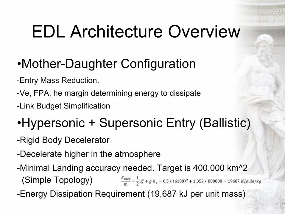
EDL Architecture Overview
•Mother-Daughter Configuration-Entry Mass Reduction.-Ve, FPA, he margin determining energy to dissipate-Link Budget Simplification
•Hypersonic + Supersonic Entry (Ballistic)-Rigid Body Decelerator-Decelerate higher in the atmosphere-Minimal Landing accuracy needed. Target is 400,000 km^2 (Simple Topology)-Energy Dissipation Requirement (19,687 kJ per unit mass)

EDL Architecture Overview (cont’d)
•Subsonic Regime-Descent time on Titan is too large (Atmospheric Sciences)-Exposed to atmospheric uncertainties for too long .- Heat Shield Separation Drag( Area, cd) Reduction Accelerated Descent.
•Landing-After 1.8 hours in Titan’s Atmosphere (3.7m/s)-No Attenuation Systems-Buoyancy Effects-Impact Load Consideration (less than 0.5 g)
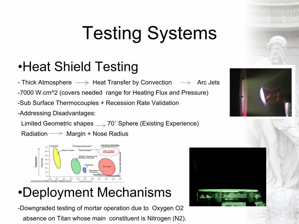
Testing Systems
•Heat Shield Testing - Thick Atmosphere Heat Transfer by Convection Arc Jets-7000 W.cm^2 (covers needed range for Heating Flux and Pressure)-Sub Surface Thermocouples + Recession Rate Validation-Addressing Disadvantages: Limited Geometric shapes 70˚ Sphere (Existing Experience) Radiation Margin + Nose Radius
•Deployment Mechanisms-Downgraded testing of mortar operation due to Oxygen O2 absence on Titan whose main constituent is Nitrogen (N2).

Testing Systems (cont’d)•Separation Parachute-Less focus on terminal Velocity-CFD Simulation and Wind Tunnels validation with High Speed cameras to Capture Inflation Dynamics.-More focus on Stability for quick inflation in a subsonic regime.
•Landing Parachute-Similar atmosphere (N2 + Density)-Flight Testing (Easy to adjust dropping altitudeto match the atmospheric model.
•Confirm Buoyancy Properties-Test of the displacememt volume in liquid ethane

Testing Systems (cont’d)
•Fully Integrated Vehicle - Thermal Vacuum Chamber testing to simulate temperature and pressure range- Anechoic Chamber to calibrate and verify antennae and RADAR- Vibration Table to verify launch and landing robustness
•Telecommunications (en route) - Bi-annual system checkouts (ping lander, compare with expected result)- Annual End-to-End relay test:
- Send test signal from Earth to orbiter and/or lander. Removes system error

Subsystems
•Aeroshell-2.5 m diameter (Drag Vs Turbulence)
-70˚ Sphere cone (Stability Vs Drag)
-Rn=0.88 (Heating Consideration)
•Heat Shield-SLA 561V (120 Kg)
-Thickness-Material
(Uncertain Aerothermal Environment + Material Performance, spallation)
•Structure-Aluminum 6061-T6 (40 Kg)
-Commonly and Previously Used
-Splashdown & Buoyancy Consideration

Subsystems (Cont’d)
•Separation Parachute-3 second Deployment, Disk-Gap-Band Stability Control-Diameter 8.5 m, Cd 0.5, Cx 1.2-Temporarily Velocity Reduction
•Landing Parachute-Conical Ribbon Low Oscillation Angle-Diameter 6m, Cd 0.5, Cx 1.2-In 100m, velocity down to 3.7 m/s
•Parachute Mechanisms 35 kg

Subsystems (Cont’d)
● Antenna Relay System-Lander uses redundant quadrifilar helix antennas, 6s delay -- S-band: 2.098GHz and 2.040GHz -- 810Mbps data rate, Gain of 11dB -- .0545m diameter x .127m length-Orbiter uses 4m parabolic reflector antenna -- X-band to Earth: 9.5 GHz -- 6kbps data rate -- Gain of 36dB (to lander) -- Gain of 49.4dB (to Goldstone 70m)
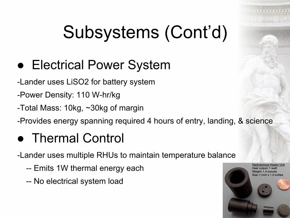
Subsystems (Cont’d)
● Electrical Power System-Lander uses LiSO2 for battery system-Power Density: 110 W-hr/kg-Total Mass: 10kg, ~30kg of margin-Provides energy spanning required 4 hours of entry, landing, & science
● Thermal Control-Lander uses multiple RHUs to maintain temperature balance -- Emits 1W thermal energy each -- No electrical system load

Telecom Data Link
● Lander-to-Orbiter Link (Quad Helix)- Requirement of Bit Error Rate (BER) of 10^-8, Required Eb/No: 12dB- 2.040Ghz and 2.098GHz Carrier Freq- SSPA output power: 7W- Data Rate: 810Mbps- System Noise Temp: 300K- Space Loss: -157dB- Atmospheric Loss: -0.03dB (!!!)- Lander antenna efficiency: 0.7- Orbiter antenna efficiency: 0.55- Max height at surface
Space Loss (Ls):

Telecom Data Link
● Orbiter-to-Earth Link (4m Parabolic)- Requirement of Bit Error Rate (BER) of 5x10^-7, Required Eb/No 11dB- 9.5GHz Carrier Freq- TWTA output power: 65W- Data Rate: 6kbps- System Noise Temp: 65K- Space Loss: -296dB- Atmospheric Loss: -5dB (Rainy Day)- Lander antenna efficiency: 0.55- Goldstone 70m antenna efficiency: 0.57
Space Loss (Ls):

Planetary Properties & Entry Challenges•Surface Density is 5.3 Kg/m^3 or 4.3 times earths
•Scale Height is 40 km almost 5 times that of earth
•The surface temperature is only 90K and the surface gravity is one seventh of earths
•This makes for a long descent through a thick atmosphere

Entry Considerations For Mission Success
● Minimise total time of descent due to short mission lifetime
● Use an entry trajectory compatible with mothership flyby trajectory and to facilitate uninterrupted uplink with mothership
● Release from mothership at an altitude of 800 km● Entry angle of 15 degrees● Entry velocity of 6.1 km/s
Required Entry Parameters
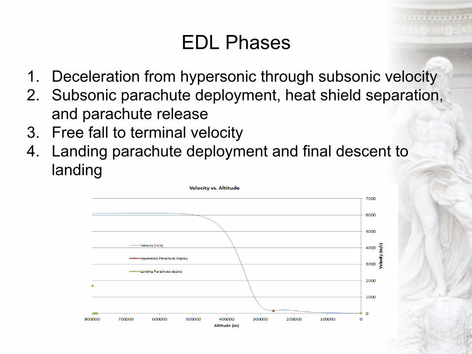
EDL Phases1. Deceleration from hypersonic through subsonic velocity2. Subsonic parachute deployment, heat shield separation,
and parachute release3. Free fall to terminal velocity4. Landing parachute deployment and final descent to
landing

First Descent Phase ● Follows initial ballistic trajectory● Velocity changes from 6100 m/s to 153 m/s● 99.94% of entry energy is dissipated in this phase● Phase where peak heating and peak deceleration
occurs
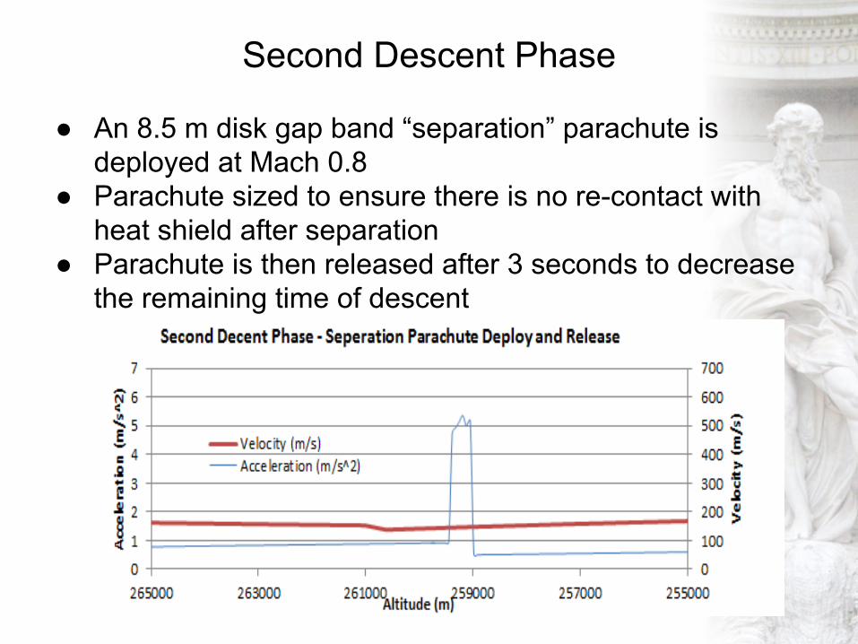
Second Descent Phase
● An 8.5 m disk gap band “separation” parachute is deployed at Mach 0.8
● Parachute sized to ensure there is no re-contact with heat shield after separation
● Parachute is then released after 3 seconds to decrease the remaining time of descent

Third Descent Phase● Free fall to terminal velocity occurring at approximately
75 km● Of note is the continued reduction in terminal velocity as
altitude decreases due to increasing density
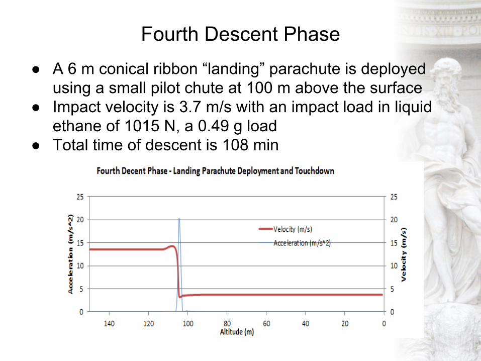
Fourth Descent Phase● A 6 m conical ribbon “landing” parachute is deployed
using a small pilot chute at 100 m above the surface● Impact velocity is 3.7 m/s with an impact load in liquid
ethane of 1015 N, a 0.49 g load● Total time of descent is 108 min
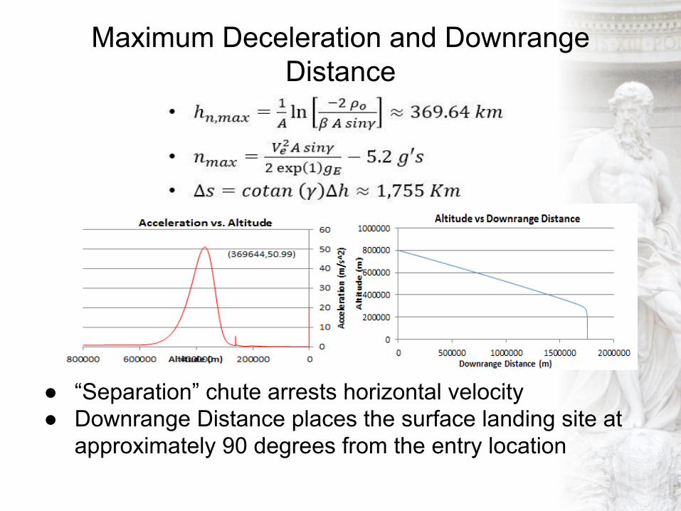
Maximum Deceleration and Downrange Distance
● “Separation” chute arrests horizontal velocity● Downrange Distance places the surface landing site at
approximately 90 degrees from the entry location

Heat Flux and Thermal Protection System
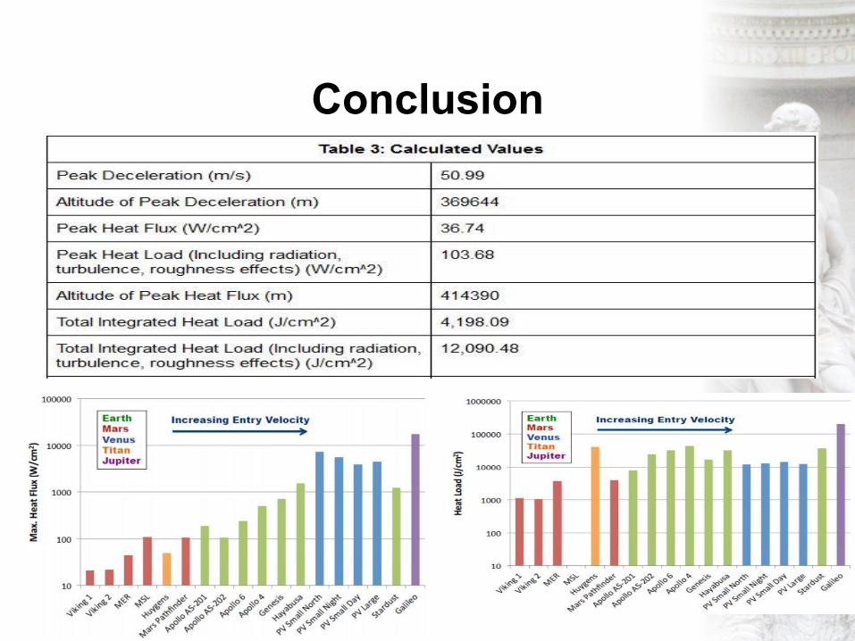
Conclusion