Ejercicios autocad dibujo tecnico
6
Bertoline−Wiebe: Fundamentals of Graphics Communication, Fifth Edition 3. Engineer i ng Geometr y Text 135 © The McGraw−Hill Companies, 2007 3.6 Using isometric grid paper, construct the X, Y, and Z axes. Reference Figure 3.4. Using the right-hand rule, place points at the following locations: a. 0,0,0 b. 4,0,0 c. 4,2,0 d. 0,2,0 e. 0,0,2 f. 4,0,2 g. 4,2,2 h. 0,2,2 Connect points a–b, b–c, c–d, d–a. Connect points e–f, f–g, g–h, h–e. Connect points d–h, c–g, a–e, b–f. What geometric solid is produced? 3.7 (Figure 3.67) Draw the offset arm, using the given dimensions. 3.8 (Figure 3.68) Draw the rocker arm gasket, using the given dimensions. 3.9 (Figure 3.69) Draw the adjustable support, using the given dimensions. 3.10 (Figure 3.70) Draw the ratchet and detent, using the given dimensions. Engineering Geometry 123 100 R38 R16 2X O38 Offset arm Figure 3.67 178 R48 O24 O64 R24 Rocker-arm gasket Figure 3.68 8.00 1.00 1.00 O2.50 R4.75 R4.75 4.00 R1.62 R1.62 1.12 2 HOLES Adjustable support Figure 3.69 1.13 ø .50 ø 1.50 ø 3.00 1.75 .63 65 ø 1.50 .25 .38 Ratchet Wheel (15 Teeth) Detent Detent Pivot ø 3.00 TYP. ø .50 ø 1.00 1.36 ø 2.75 1.50 1.40 Ratchet and detent Figure 3.70
-
Upload
ing-miguel-angel-rmz-hdez -
Category
Documents
-
view
324 -
download
2
Transcript of Ejercicios autocad dibujo tecnico
7/24/2019 Ejercicios autocad dibujo tecnico
http://slidepdf.com/reader/full/ejercicios-autocad-dibujo-tecnico 1/5
Bertoline−Wiebe:
Fundamentals of Graphics
Communication, Fifth
Edition
3. Engineer ing Geometry Text 135© The McGraw−Hill
Companies, 2007
3.6 Using isometric grid paper, construct the X, Y, andZ axes. Reference Figure 3.4. Using the right-hand
rule, place points at the following locations:
a. 0,0,0
b. 4,0,0
c. 4,2,0
d. 0,2,0
e. 0,0,2
f. 4,0,2
g. 4,2,2
h. 0,2,2
Connect points a–b, b–c, c–d, d–a.
Connect points e–f, f–g, g–h, h–e.
Connect points d–h, c–g, a–e, b–f.
What geometric solid is produced?
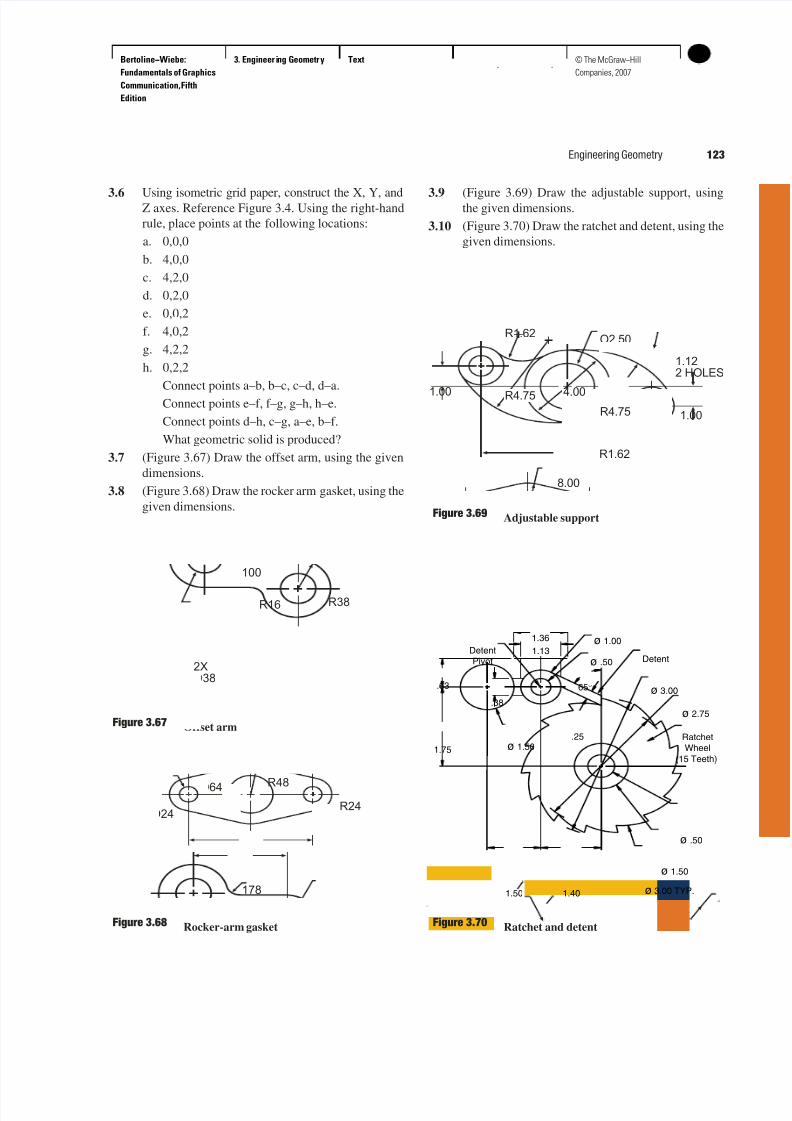
3.7 (Figure 3.67) Draw the offset arm, using the given
dimensions.
3.8 (Figure 3.68) Draw the rocker arm gasket, using the
given dimensions.
3.9 (Figure 3.69) Draw the adjustable support, usingthe given dimensions.
3.10 (Figure 3.70) Draw the ratchet and detent, using the
given dimensions.
Engineering Geometry 123
100
R38R16
2X
O38
Offset armFigure 3.67
178
R48
O24
O64
R24
Rocker-arm gasketFigure 3.68
8.00
1.00
1.00
O2.50
R4.75
R4.75 4.00
R1.62
R1.62
1.12
2 HOLES
Adjustable supportFigure 3.69
1.13
ø .50
ø 1.50
ø 3.00
1.75
.63 65°
ø 1.50.25
.38
Ratchet
Wheel
(15 Teeth)
DetentDetent
Pivot
ø 3.00 TYP.
ø .50
ø 1.001.36
ø 2.75
1.50 1.40
Ratchet and detentFigure 3.70
7/24/2019 Ejercicios autocad dibujo tecnico
http://slidepdf.com/reader/full/ejercicios-autocad-dibujo-tecnico 2/5
Bertoline−Wiebe:
Fundamentals of Graphics
Communication, Fifth
Edition
3. Engineer ing Geometry Text136 © The McGraw−Hill
Companies, 2007
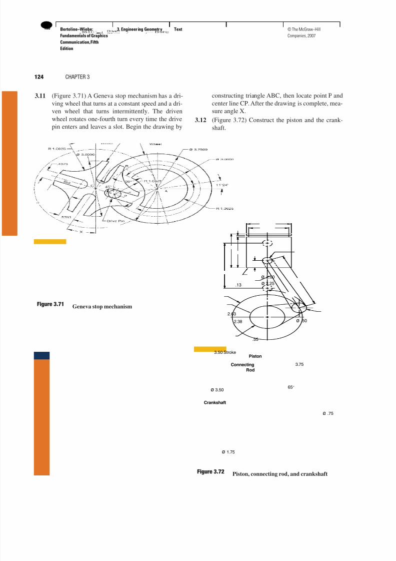
3.11 (Figure 3.71) A Geneva stop mechanism has a dri-ving wheel that turns at a constant speed and a dri-
ven wheel that turns intermittently. The driven
wheel rotates one-fourth turn every time the drive
pin enters and leaves a slot. Begin the drawing by
constructing triangle ABC, then locate point P andcenter line CP. After the drawing is complete, mea-
sure angle X.
3.12 (Figure 3.72) Construct the piston and the crank-
shaft.
124 CHAPTER 3
Geneva stop mechanismFigure 3.71
ø 2.25
2.38
.13
2.63
3.50 Stroke
.55
ø .50
3.75
65°ø 3.50
ø 1.75
ø .75
Piston
Connecting
Rod
Crankshaft
ø 2.00
Piston, connecting rod, and crankshaftFigure 3.72
7/24/2019 Ejercicios autocad dibujo tecnico
http://slidepdf.com/reader/full/ejercicios-autocad-dibujo-tecnico 3/5
Bertoline−Wiebe:
Fundamentals of Graphics
Communication, Fifth
Edition
3. Engineer ing Geometry Text 137© The McGraw−Hill
Companies, 2007
3.13 Create an A-size drawing sheet, then constructa helix from a right circular cylinder that has a
2-inch-diameter base and is 4 high.
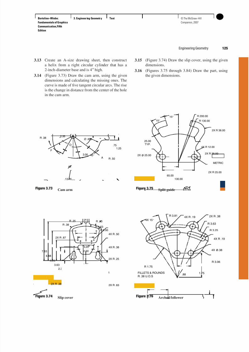
3.14 (Figure 3.73) Draw the cam arm, using the given
dimensions and calculating the missing ones. The
curve is made of five tangent circular arcs. The rise
is the change in distance from the center of the hole
in the cam arm.
3.15 (Figure 3.74) Draw the slip cover, using the givendimensions.
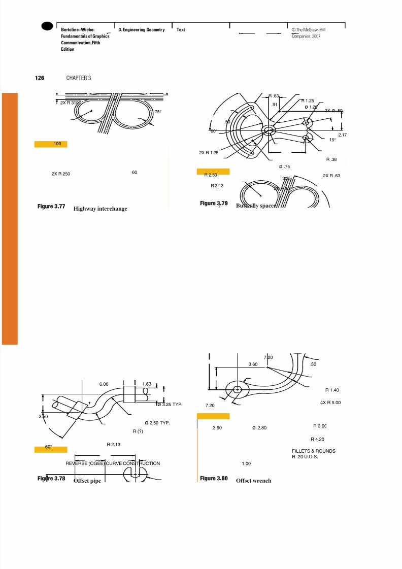
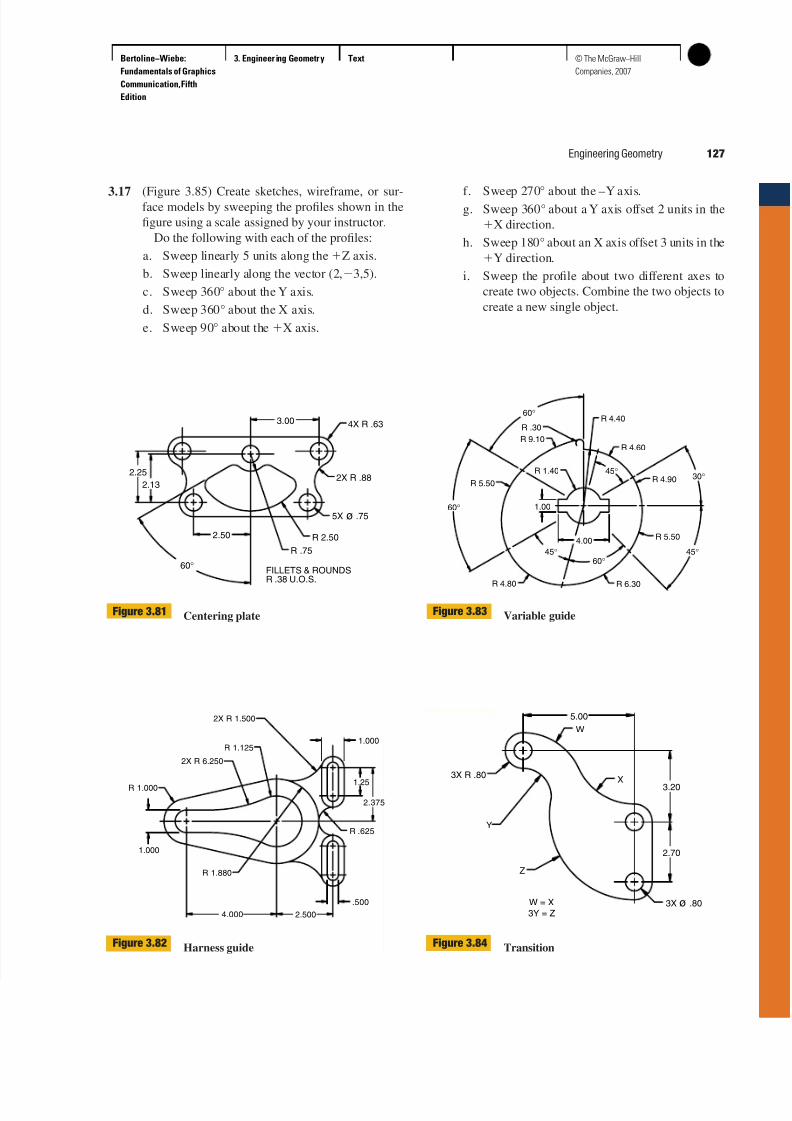
3.16 (Figures 3.75 through 3.84) Draw the part, using
the given dimensions.
Engineering Geometry 125
.751.25
2.35
35°
40°
O
42°
32°
A
B
CD
E
F
3.00
R .50
R .38Ø .625
.13 RISE.25 RISE
.06 RISE
Cam armFigure 3.73
Slip coverFigure 3.74
1.51
2.37
3.63
5.25
.45
4X R .50
R .50R .25
R 5.00
1.88
R 4.63
3.25
2.50
1.75
R .38
1.38
2X R .632X R .38
2X R .87
2X R .25
4X R .38
6.88
7.63
R 200.00
R 130.00
130.00
15°
65.00
2X ø 25.00
25.00
TYP.
2X R 25.00
2X R 38.00
4X R 12.00
2X R 25.00
15°
METRIC
Split guideFigure 3.75
4X 15°
.881.75
4X R .19
4X R .19
R 1.75
R 3.06
2X R .38
R 3.63
R 3.25
R 3.81
FILLETS & ROUNDS
R .38 U.O.S
4X ø.38
Arched followerFigure 3.76
7/24/2019 Ejercicios autocad dibujo tecnico
http://slidepdf.com/reader/full/ejercicios-autocad-dibujo-tecnico 4/5
Bertoline−Wiebe:
Fundamentals of Graphics
Communication, Fifth
Edition
3. Engineer ing Geometry Text138 © The McGraw−Hill
Companies, 2007
126 CHAPTER 3
2X R 310
2X R 250
75°
100
60
Highway interchangeFigure 3.77
6.00 1.63
R 2.1360°
3.50
ø 2.50 TYP.
ø 3.25 TYP.
R (?)
REVERSE (OGEE) CURVE CONSTRUCTION
Offset pipeFigure 3.78
15°
R .38
2X R .63
2X ø .50ø 1.26
R 1.25
ø .75
3.25
R .63
2X R .63
.50
60°
2X R 1.25
R 2.50
R 3.13
.91
2.17
Butterfly spacerFigure 3.79
7.204X R 5.00
R 1.40
.50
FILLETS & ROUNDS
R .20 U.O.S.
7.20
1.00
R 4.20
R 3.00ø 2.80
3.60
3.60
Offset wrenchFigure 3.80
7/24/2019 Ejercicios autocad dibujo tecnico
http://slidepdf.com/reader/full/ejercicios-autocad-dibujo-tecnico 5/5
Bertoline−Wiebe:
Fundamentals of Graphics
Communication, Fifth
Edition
3. Engineer ing Geometry Text 139© The McGraw−Hill
Companies, 2007
3.17 (Figure 3.85) Create sketches, wireframe, or sur-face models by sweeping the profiles shown in the
figure using a scale assigned by your instructor.
Do the following with each of the profiles:
a. Sweep linearly 5 units along theZ axis.
b. Sweep linearly along the vector (2,3,5).
c. Sweep 360° about the Y axis.
d. Sweep 360° about the X axis.
e. Sweep 90° about the X axis.
f. Sweep 270° about the –Y axis.g. Sweep 360° about a Y axis offset 2 units in the
X direction.
h. Sweep 180° about an X axis offset 3 units in the
Y direction.
i. Sweep the profile about two different axes to
create two objects. Combine the two objects to
create a new single object.
Engineering Geometry 127
3.00
2X R .88
4X R .63
2.50
60°
R .75
R 2.50
FILLETS & ROUNDSR .38 U.O.S.
2.13
2.25
5X ø .75
Centering plateFigure 3.81
R 1.125
2X R 6.250
1.000
R 1.000
4.000 2.500
2X R 1.500
R 1.880
.500
1.000
R .625
1.25
2.375
Harness guideFigure 3.82
R 4.40
R 4.60
R 5.50
R 6.30R 4.80
45°
4.00
R 4.90
60°45°
R 1.40
R 9.10
60°
1.00
R 5.50
60°
45°
30°
R .30
Variable guideFigure 3.83
2.70
3.20
5.00
3X ø .80
X
W
Z
3X R .80
Y
W = X
3Y = Z
TransitionFigure 3.84