
GUÍA DE REFERENCIA DE COMANDOS CISCO...GUÍA DE REFERENCIA DE COMANDOS CISCO Guía de comandos de...
188
GUÍA DE REFERENCIA DE COMANDOS CISCO Guía de comandos de Cisco desde Básico hacia Avanzado, con este manual usted podrá encontrar ejemplos al más alto nivel de expertos en configuraciones CISCO
Transcript of GUÍA DE REFERENCIA DE COMANDOS CISCO...GUÍA DE REFERENCIA DE COMANDOS CISCO Guía de comandos de...
GUÍA DE REFERENCIA DE COMANDOS CISCO
Guía de comandos de Cisco desde Básico hacia Avanzado, con este
manual usted podrá encontrar ejemplos al más alto nivel de expertos en
configuraciones CISCO
1 Ing. Gerardo Morales https://mr-telecomunicaciones.com [email protected]
Contenido
Comandos Básicos ...............................................................................................................9
Copiar el Running config al Startup ...............................................................9
Ver la configuración ..................................................................................................9
Habilitar CDP .............................................................................................................10
Habilitar CDP por interfaz ..............................................................................10
Monitorear y mantener CDP ....................................................................................10
LLDP ......................................................................................................................................10
Habilitar LLDP ..........................................................................................................10
Show Commands .............................................................................................................10
Cambiar el nombre al Router o Switch ..........................................................10
Configurar enlaces WAN SERIALES ......................................................................10
Configurar interfaces fastethernet ...............................................................11
Mensajes no solicitados de iOS.........................................................................11
Configurar Mensaje de Ingreso a los router o switchs .....................11
Configurar PoE ..............................................................................................................11
Contraseñas .........................................................................................................................11
Consola ...............................................................................................................................11
Telnet .................................................................................................................................11
SSH ........................................................................................................................................12
MTU ...........................................................................................................................................13
IPv4 ........................................................................................................................................13
IPv6 ........................................................................................................................................13
NAT ............................................................................................................................................13
Static NAT ........................................................................................................................13
Configurando Dynamic NAT .......................................................................................13
Configurar PAT OVERLOAD .........................................................................................14
Clear Commands ..............................................................................................................15
Troueblesooting ............................................................................................................15
DHCP ..........................................................................................................................................15
Configurar DHCP ............................................................................................................15
Configurando IP-Helper Address.........................................................................16
Troublesooting ..............................................................................................................16
2 Ing. Gerardo Morales https://mr-telecomunicaciones.com [email protected]
IP SLA .....................................................................................................................................17
Configurar IP SLA .......................................................................................................17
Troubleshooting ............................................................................................................17
SNMP ..........................................................................................................................................18
SNMPv2c ...............................................................................................................................18
Configurar SNMPv2c Support for Trap and Inform ...................................18
Troubleshooting ............................................................................................................18
SNMPv3 .................................................................................................................................19
Administrando archivos IOS ......................................................................................20
Actualizando imágenes IOS ....................................................................................20
Copiando imágenes con TFTP ..................................................................................20
Verificando integridad de IOS con MD5 ........................................................20
Copiando imágenes con FTP ....................................................................................21
Copiando imágenes con SCP ....................................................................................22
Copiar un archivo en una unidad USB .............................................................23
Configuración tradicional de backup y restauración con el
comando copy ...................................................................................................................23
Alternativas para la configuración de Backup y la restauración
de manera automática ................................................................................................23
Borrando Archivos de Configuración ...............................................................23
Comandos Antiguos ...................................................................................................23
Comandos Nuevos ........................................................................................................24
Troubleshooting ............................................................................................................24
Administración de las licencias de IOS ......................................................24
Activación manual de licencias IOS ...........................................................24
Licencias de Derecho de Uso (60 días) ........................................................27
Troubleshooting ............................................................................................................27
Access Control List (ACL) ........................................................................................27
ACL Standars ...............................................................................................................27
Borrar Access List .....................................................................................................29
Opción de Host ..............................................................................................................30
Rangos de Access List ..............................................................................................30
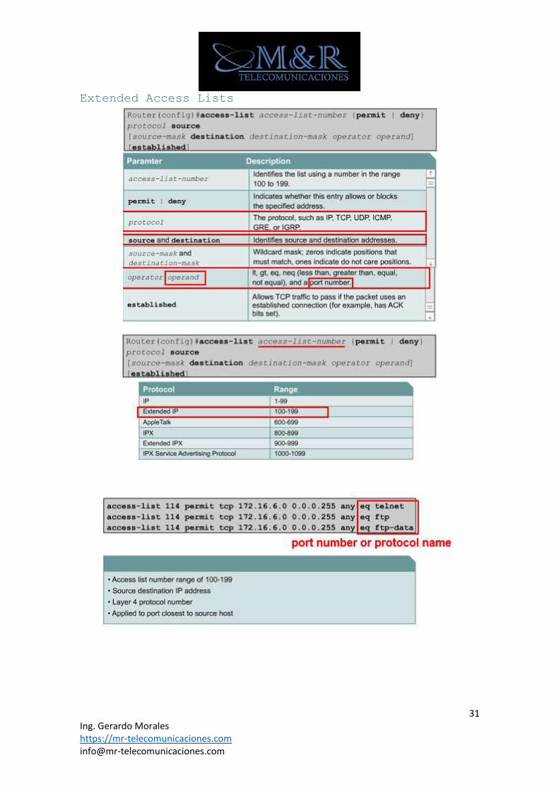
Extended Access Lists ..............................................................................................31
3 Ing. Gerardo Morales https://mr-telecomunicaciones.com [email protected]
Named ACLs ........................................................................................................................32
Criterio de ubicación de la ACL Extendidas ............................................34
Colocando Estándar Acess List ...........................................................................35
Restricción del acceso de terminal virtual a un router ................36
IPV6 ACL ............................................................................................................................36
Verificar IPv6 ACLs...............................................................................................40
Configurar Rutas Estáticas ......................................................................................40
Borrar rutas estáticas ...........................................................................................41
Configurar rutas por defecto .................................................................................41
Debug .......................................................................................................................................41
Uso de enrutamiento de IP de depuración ...................................................41
Protocolos de Enrutamiento ......................................................................................41
Classfull ..........................................................................................................................41
Classless ..........................................................................................................................41
IPv6 ......................................................................................................................................41
Distancia Administrativa .......................................................................................41
Verificando distancia administrativa y tipo de Protocolo ...........42
RIPv1 ...................................................................................................................................42
Configurando RIPv1 .................................................................................................42
Verificación y solución de problemas ......................................................42
Configurar Passive Interface .........................................................................42
Desabilitando Automatic Summarization ....................................................42
Configurar Default-Information Originate .............................................43
RIPv2 ...................................................................................................................................43
Configurando RIPv2 .................................................................................................43
Verificación y solución de problemas ......................................................43
Desabilitando Automatic Summarization ....................................................43
Configurar Default-Information Originate .............................................43
Configurar Passive Interface .........................................................................43
Verificando actualizaciones ............................................................................43
EIGRP (Distance Vector Protocol) ....................................................................43
Enabling EIGRP Routing .......................................................................................44
EIGRP Interface commands ...................................................................................44
4 Ing. Gerardo Morales https://mr-telecomunicaciones.com [email protected]
Miscellaneous .............................................................................................................44
Show commands .............................................................................................................44
Modificar la métrica EIGRP ..............................................................................45
Configurando Hello Intervals and Hold Times ......................................45
Troubleshooting ............................................................................................................45
Dirección muticast .....................................................................................................46
OSPF (Link-state routing protocol) ...............................................................46
Configuring OSPF Routing ...................................................................................46
Prioritizing the DR (Router ID) ..................................................................46
Show commands .............................................................................................................46
Timers .............................................................................................................................47
Miscellaneous .............................................................................................................47
Referencia rápida: OSPF Routing - Multiple Areas ........................47
Configuring OSPF Routing ...................................................................................48
OSPF Routing - Area Range (Summarization) ...........................................49
Troubleshooting .................................................................................................................49
IPv6 ..........................................................................................................................................50
Comando para habilitar IPv6 ................................................................................50
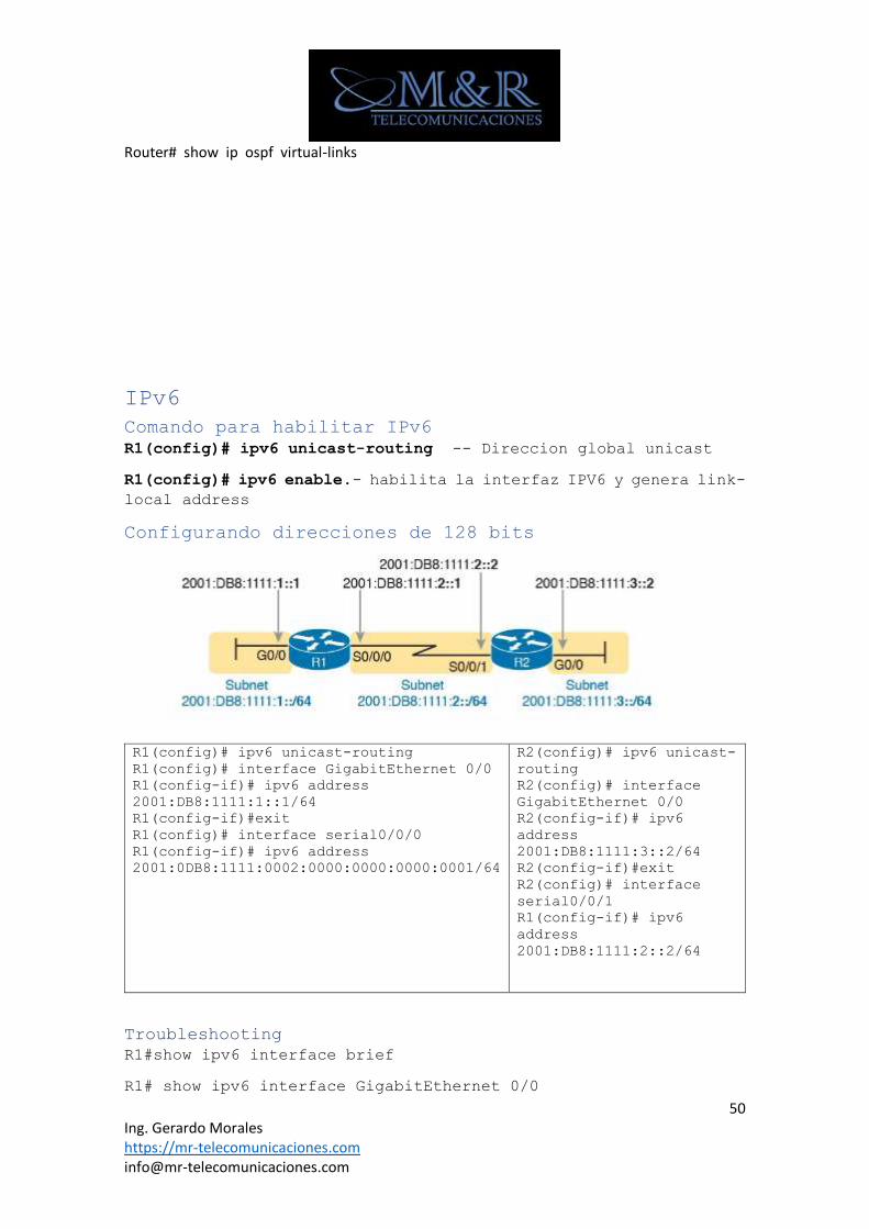
Configurando direcciones de 128 bits ..........................................................50
Troubleshooting ........................................................................................................50
Generando interface única ID usando EUI-64 Modificado ..................51
Configurando IPv6 interfaces usando EUI-64 ............................................52
Configuración de dirección Dynamic Unicast ............................................52
Configurando y Verificando Anycast Address ............................................52
Troubleshooting ............................................................................................................53
Configurando IPv6 DHCP Relay .............................................................................53
Configurando rutas Estaticas con IPv6 ........................................................53
Configurando Rutas por Defecto.........................................................................54
Configurando Rutas por Defecto con SLAAC sobre las interfaces
del Router ........................................................................................................................54
Troubleshooting para Rutas Estaticas ..........................................................54
RIPNG ...................................................................................................................................55
Configurando RIPng .................................................................................................55
5 Ing. Gerardo Morales https://mr-telecomunicaciones.com [email protected]
Propagando Default Route ...................................................................................55
EIGRP for IPv6 ..............................................................................................................56
Dirección de Multicast .......................................................................................56
Show commands .............................................................................................................56
Sumarizacion Manual...............................................................................................56
Configuración de EIGRP for IPv6 ..................................................................56
OSPF V3 .............................................................................................................................101
Show Commands ...........................................................................................................101
Configurando Interfaces ...................................................................................101
RADIUS Server...................................................................................................................129
Show Commands ...............................................................................................................129
Dialer Interface ...........................................................................................................129
Switching ............................................................................................................................130
VLANS .................................................................................................................................130
Crear un Vlan ...........................................................................................................130
Configuración de un Puerto Troncal .........................................................130
Configurando Puertos de Acesso ...................................................................130
Configurar VLAN ......................................................................................................131
Asignando un Puerto a una VLAN ...................................................................131
Borrando VLANs ........................................................................................................131
Configurando VLAN Nativa .................................................................................131
Configurando Private Vlans ............................................................................131
Configurando Asociaciones de puertos en PVlans .............................132
Troubleshooting ......................................................................................................132
Vlan de Voz ...................................................................................................................132
Switchport voice vlan none ............................................................................133
Switchport voice vlan dot1p ..........................................................................133
Switchport voice vlan untagged ...................................................................133
Switchport voice vlan vvid (opción recomendada)...........................133
VTP ......................................................................................................................................133
Configurando Dominios ........................................................................................133
Configurando el servidor y cliente .........................................................133
Configurando VTP Pruning .................................................................................133
6 Ing. Gerardo Morales https://mr-telecomunicaciones.com [email protected]
EtherChannel .................................................................................................................133
Configurando EtherChannel Load Balancing ...........................................133
Asignando puertos y configurando el protocolo ...............................134
Configurando metodos en Pagp .......................................................................134
Configurando LACP .................................................................................................134
Troubleshooting ......................................................................................................135
Spanning tree (STP) ................................................................................................135
Configurando STP ....................................................................................................135
Configurando un Root Bridge ..........................................................................135
Cambiar el Root Bridge .....................................................................................135
Configurando PortFast ........................................................................................135
Configuración de BPDU GUARD ..........................................................................136
Configuración de Root Guard ..........................................................................136
Implementar PVST ....................................................................................................136
Implementar PVST+ .................................................................................................136
Implementar Multiple Spanning Tree Protocol (MSTP) ...................137
Troubleshooting ......................................................................................................137
DHCPv6 ...............................................................................................................................138
Troublesooting ........................................................................................................139
WAN ..........................................................................................................................................140
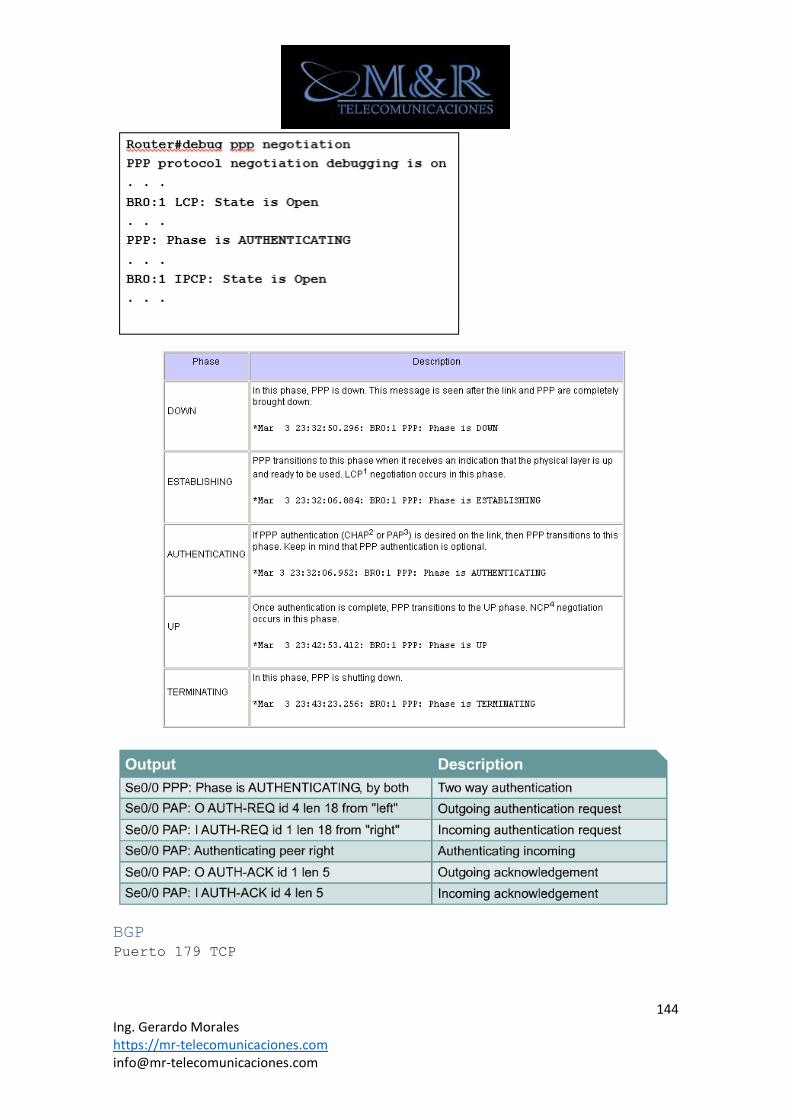
Comandos PPP .................................................................................................................140
Configurar PPP ........................................................................................................140
Verificación de PPP.............................................................................................140
Configuración de la autenticación (PAP o CHAP) .............................141
Configuring PPP Multilink (MLP) ................................................................142
Error Detection ......................................................................................................143
Troubleshooting ......................................................................................................143
BGP ......................................................................................................................................144
Configuración de EBGP ........................................................................................145
Configurar rutas de descarte .......................................................................145
Show Commands ...........................................................................................................145
Estado vecino con el Neighbor Shut Down .............................................145
Alta disponibilidad ....................................................................................................145
7 Ing. Gerardo Morales https://mr-telecomunicaciones.com [email protected]
HSRP ....................................................................................................................................145
Configuración HSRP Switchs ............................................................................145
Autenticación texto plano ..............................................................................146
Autenticación MD5 .................................................................................................146
Configurando HSRP Interface Tracking ....................................................146
Configuración HSRP Routers ............................................................................147
Configurar HSRP Interface Tracking .........................................................148
Diferencias entre HSRPv1 y HSRPv2............................................................148
Troubleshooting ......................................................................................................148
VRRP (Virtual Router Redundancy Protocol) .............................................149
GBLP ....................................................................................................................................149
Configurar GBLP ......................................................................................................149
GLBP Interface Tracking ...................................................................................150
Netflow IOS .......................................................................................................................150
SPAN ........................................................................................................................................150
Configurar Local SPAN ............................................................................................150
Configurar SPAN ..........................................................................................................151
Troubleshooting ..........................................................................................................151
Seguridad ............................................................................................................................152
Switch Security ..........................................................................................................152
BPDU GUARD ..................................................................................................................152
Root Guard ..................................................................................................................152
Port Security ...........................................................................................................153
Troubleshooting Port security .....................................................................153
DHCP SNOOPING ...........................................................................................................154
IP Source Guard ......................................................................................................155
Troubleshooting DHCP SNOOPING .....................................................................155
Prevencion de ARP Spoofing ................................................................................155
Mejorando seguridad en Telnet .....................................................................156
HTTP Secure Server ...............................................................................................156
Authentication, Authorization, and Accounting (AAA) .................157
TACACS+ .........................................................................................................................157
Radius ...........................................................................................................................157
8 Ing. Gerardo Morales https://mr-telecomunicaciones.com [email protected]
Accounting ..................................................................................................................158
Security Using IEEE 802.1X Port-Based Authentication ............158
QoS ..........................................................................................................................................159
Configurando CoS trust using the IOS ........................................................159
Asignando CoS on a per-port basis ...............................................................159
Reescribiendo el CoS ..............................................................................................160
Implementing QoS for Voice ................................................................................160
Configuración de QoS para voz .........................................................................160
Auto QoS ..........................................................................................................................160
Interfaz de línea de comandos de QoS modular (CLI) .......................160
Classification of traffic – The class-map .........................................160
Definiendo the QoS policy – The policy-map ......................................161
Aplicando the policy to an interface – The service-policy ...161
IP Precedence and DSCP .........................................................................................161
Configuración de la confianza cos mediante el iOS ......................161
Asignando CoS on a per-port basis............................................................162
Rescribiendo the CoS ..........................................................................................162
Usando a MAC ACL to assign a DSCP value .............................................162
Configurando DSCP usando a MAC ACL .........................................................162
Uso de una ACL IP para definir el DSCP o la precedencia ........163
Configuración weighted fair queuing (WFQ) .............................................163
Configuración Class-Based Weighted Fair Queuing ..............................164
CBWFQ Using WRED Packet Drop .......................................................................164
Low Latency Queuing (LLQ) ..................................................................................164
Multicast ............................................................................................................................165
PIM ......................................................................................................................................165
Configuración RPs .................................................................................................166
IGMP - Internet Group Management Protocol .............................................166
Configuración de las joins IGMP ................................................................166
CGMP ................................................................................................................................166
VPN ..........................................................................................................................................167
GRE ......................................................................................................................................167
IPSEC VPN ........................................................................................................................168
9 Ing. Gerardo Morales https://mr-telecomunicaciones.com [email protected]
Paso 1 Configurar las interfaces ..............................................................168
Paso 2 Configurar EIGRP ...................................................................................169
Paso 3 Crear Políticas IKE ............................................................................169
Paso 4 Configurar pre-shared keys............................................................169
Paso 5 configurar IPsec transform set Lifetimes...........................170
Paso 6 definir interesting traffic .........................................................170
Paso 7 Crear y aplicar Crypto Maps .........................................................170
Paso 8 Verificar Ipsec configuration ....................................................170
Paso 9 Verificar operación IPSEC ..............................................................170
Paso 10 Probar ........................................................................................................171
MPLS ........................................................................................................................................172
Comandos Básicos
Copiar el Running config al Startup
Router# copy running-config startup-config
Ver la configuración
Router# show running-config
Router# show ip route
Router# show ip interface brief
10 Ing. Gerardo Morales https://mr-telecomunicaciones.com [email protected]
Router# show interfaces
R1# show interfaces fastethernet 0/0
R1# show controllers serial 0/0/0
Habilitar CDP
Switch(config)# cdp run
Router(config)# no cdp run -------------- Deshabilitar CDP
Habilitar CDP por interfaz
Switch(config)# interface fastethernet 5/1
Switch(config-if)# cdp enable
Switch(config)# interface fastethernet 5/1
Switch(config-if)# no cdp enable
Monitorear y mantener CDP
Switch# clear cdp counters
Switch# clear cdp table
Switch# show cdp
R3# show cdp neighbors
R3# show cdp neighbors detail ----Se puede visualizar la IP del
router remoto
LLDP
Habilitar LLDP
switch(config)# lldp run
switch(config)# end
Switch(config)# interface fastethernet 5/1
Switch(config-if)# lldp enable
Show Commands
R1#show lldp neighbors
Cambiar el nombre al Router o Switch
Router# configure terminal
Router(config)# hostname R1
Configurar enlaces WAN SERIALES
R1(config)# interface Serial0/0
R1(config-if)# ip address 192.168.2.1 255.255.255.0
R1(config-if)# description Link to R2
R1(config-if)# clock rate 64000 DCE Only
11 Ing. Gerardo Morales https://mr-telecomunicaciones.com [email protected]
R1(config-if)# no shutdown
Configurar interfaces fastethernet
R1(config)# interface fastethernet0/0
R1(config-if)# ip address 172.16.3.1 255.255.255.0
R1(config-if)# no shutdown
R1(config-if)# description R1 LAN
R1(config-if)# no shutdown
Mensajes no solicitados de iOS
Para mantener la salida no solicitada separada de la entrada,
introduzca el modo de configuración de línea para el puerto de la
consola y añada el logging synchronous
R1(config)# line console 0
R1(config-line)# logging synchronous
Configurar Mensaje de Ingreso a los router o switchs
Router(config)# banner motd # message #
Configurar PoE
Switch(config)# interface type mod/num
Switch(config-if)# power inline {auto [max milli-watts] | never
| static [max milli-watts]}
Ejemplo
Switch(config)# interface fastethernet 0/1
Switch(config-if)# power inline auto
Switch# show power inline fastethernet 0/1
Contraseñas
Consola
Router(config)# enable secret password privilege password
Router(config)# line console 0 console password
Router(config-line)# password password
Router(config-line)# login
Telnet
Router(config)# line vty 0 4 telnet password
Router(config-line)# password password
Router(config-line)# login
12 Ing. Gerardo Morales https://mr-telecomunicaciones.com [email protected]
SSH
Paso 1
• Switch(config)# Hostname SW1
• SW1(config)# ip domain-name example.com
• SW1(config)#crypto key generate rsa
How many bits in the module [512]: 1024
Paso 2
• SW1(config)#ip ssh version 2
Paso 3 (Opcional)
Router(config-line)# transport input ssh
Este comando asegura que solo las conexiones SSH son permitidas,
nadie por medio de telnet tendrá una conexión exitosa hacia el
router
Paso 4
• SW1(config)#line vty 0 15
• SW1(config-line)#login local
• SW1(config-line)#exit
• SW1(config)#username wendell password odom
• SW1(config)#username chris password youdaman
Ejemplo 2
switch(config)# username xyz password abc123
switch(config)# ip domain-name xyz.com
switch(config)# crypto key generate rsa
switch(config)# ip ssh version 2
switch(config)# line vty 0 15
switch(config-line)# login local
switch(config-line)# transport input ssh
13 Ing. Gerardo Morales https://mr-telecomunicaciones.com [email protected]
MTU
IPv4 R1(config)# interface gigabitethernet 0/0
R1(config-if)# ipv4 mtu 1400
IPv6 R1(config)# interface gigabitethernet 0/0
R1(config-if)# ipv6 mtu 1400
NAT
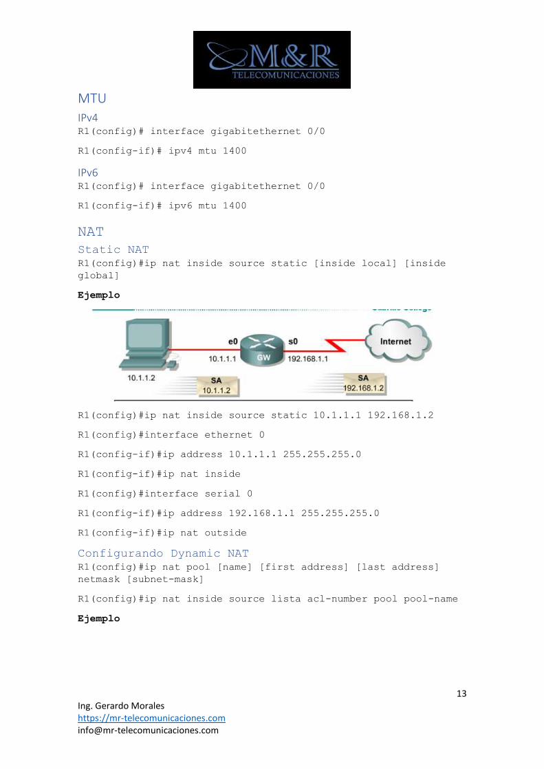
Static NAT
R1(config)#ip nat inside source static [inside local] [inside
global]
Ejemplo
R1(config)#ip nat inside source static 10.1.1.1 192.168.1.2
R1(config)#interface ethernet 0
R1(config-if)#ip address 10.1.1.1 255.255.255.0
R1(config-if)#ip nat inside
R1(config)#interface serial 0
R1(config-if)#ip address 192.168.1.1 255.255.255.0
R1(config-if)#ip nat outside
Configurando Dynamic NAT
R1(config)#ip nat pool [name] [first address] [last address]
netmask [subnet-mask]
R1(config)#ip nat inside source lista acl-number pool pool-name
Ejemplo
14 Ing. Gerardo Morales https://mr-telecomunicaciones.com [email protected]
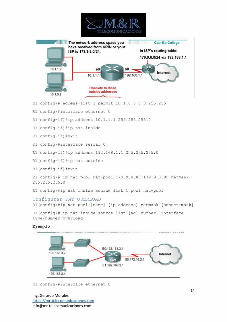
R1(config)# access-list 1 permit 10.1.0.0 0.0.255.255
R1(config)#interface ethernet 0
R1(config-if)#ip address 10.1.1.1 255.255.255.0
R1(config-if)#ip nat inside
R1(config-if)#exit
R1(config)#interface serial 0
R1(config-if)#ip address 192.168.1.1 255.255.255.0
R1(config-if)#ip nat outside
R1(config-if)#exit
R1(config)# ip nat pool nat-pool 179.9.8.80 179.9.8.95 netmask
255.255.255.0
R1(config)#ip nat inside source list 1 pool nat-pool
Configurar PAT OVERLOAD
R1(config)#ip nat pool [name] [ip address] netmask [subnet-mask]
R1(config)# ip nat inside source list [acl-number] interface
type/number overload
Ejemplo
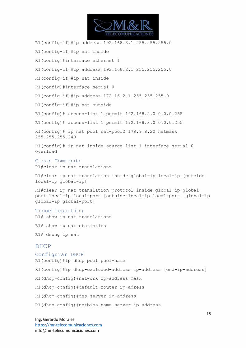
R1(config)#interface ethernet 0
15 Ing. Gerardo Morales https://mr-telecomunicaciones.com [email protected]
R1(config-if)#ip address 192.168.3.1 255.255.255.0
R1(config-if)#ip nat inside
R1(config)#interface ethernet 1
R1(config-if)#ip address 192.168.2.1 255.255.255.0
R1(config-if)#ip nat inside
R1(config)#interface serial 0
R1(config-if)#ip address 172.16.2.1 255.255.255.0
R1(config-if)#ip nat outside
R1(config)# access-list 1 permit 192.168.2.0 0.0.0.255
R1(config)# access-list 1 permit 192.168.3.0 0.0.0.255
R1(config)# ip nat pool nat-pool2 179.9.8.20 netmask
255.255.255.240
R1(config)# ip nat inside source list 1 interface serial 0
overload
Clear Commands
R1#clear ip nat translations
R1#clear ip nat translation inside global-ip local-ip [outside
local-ip global-ip]
R1#clear ip nat translation protocol inside global-ip global-
port local-ip local-port [outside local-ip local-port global-ip
global-ip global-port]
Troueblesooting
R1# show ip nat translations
R1# show ip nat statistics
R1# debug ip nat
DHCP
Configurar DHCP
R1(config)#ip dhcp pool pool-name
R1(config)#ip dhcp-excluded-address ip-address [end-ip-address]
R1(dhcp-config)#network ip-address mask
R1(dhcp-config)#default-router ip-adress
R1(dhcp-config)#dns-server ip-address
R1(dhcp-config)#netbios-name-server ip-address
16 Ing. Gerardo Morales https://mr-telecomunicaciones.com [email protected]
R1(dhcp-config)#domain-name name
Ejemplo
Router (config) #ip excluded-address 172.16.1.254
Router (config) dhcp pool subnet12
Router (dhcp-config)#network 172 . 16. 12.0 255.255 .255.0
Router (dhcp—config)# default-router 172.16.12.254
Router (dhcp—config)#dns-server 172. 16. 1.2
R1(dhcp-config)#netbios-name-server 172.16.1.3
Router (dhc-confi )#domain—name foo.com
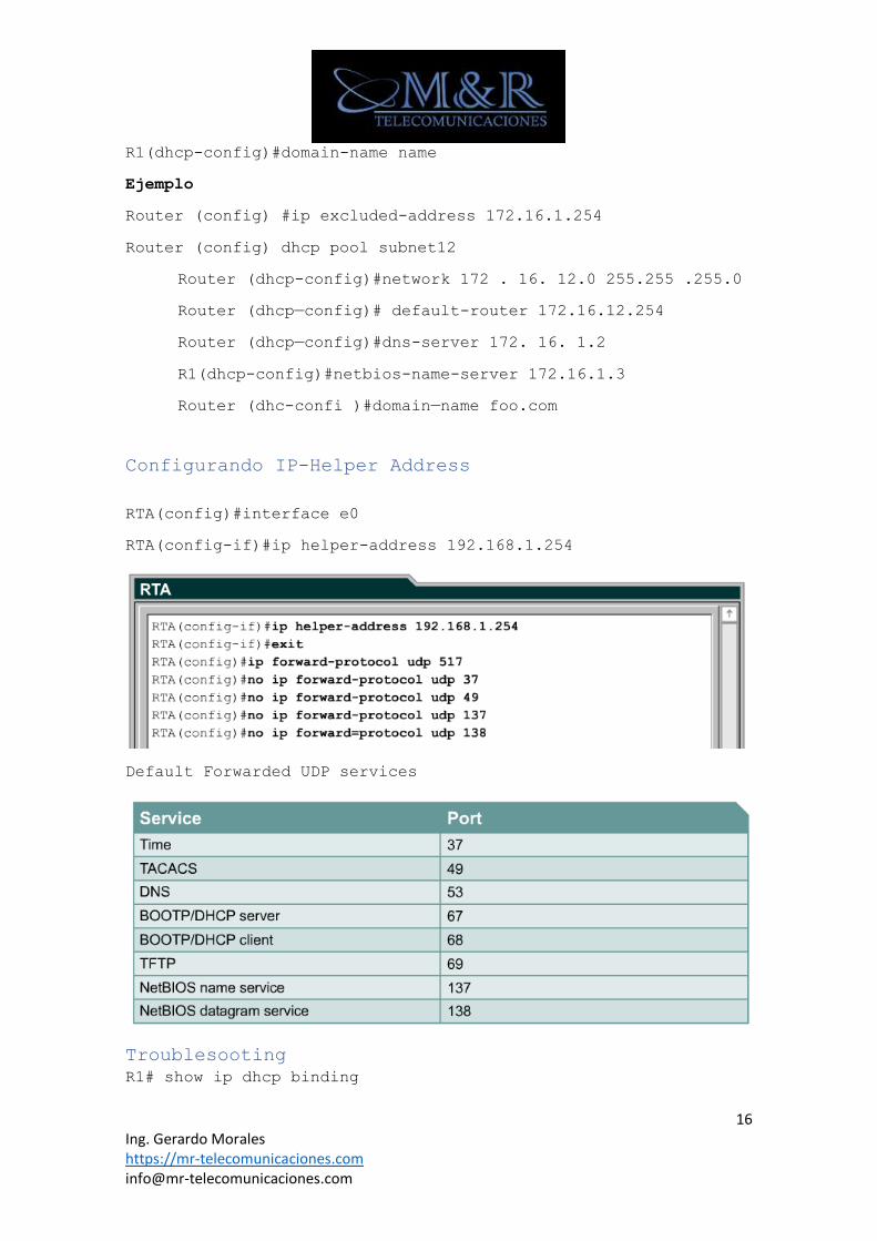
Configurando IP-Helper Address
RTA(config)#interface e0
RTA(config-if)#ip helper-address 192.168.1.254
Default Forwarded UDP services
Troublesooting
R1# show ip dhcp binding
17 Ing. Gerardo Morales https://mr-telecomunicaciones.com [email protected]
R1# debug ip dhcp server events
IP SLA
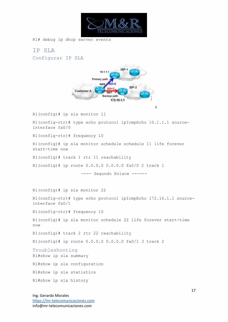
Configurar IP SLA
R1(config)# ip sla monitor 11
R1(config-rtr)# type echo protocol ipIcmpEcho 10.1.1.1 source-
interface fa0/0
R1(config-rtr)# frequency 10
R1(config)# ip sla monitor schedule schedule 11 life forever
start-time now
R1(config)# track 1 rtr 11 reachability
R1(config)# ip route 0.0.0.0 0.0.0.0 fa0/0 2 track 1
---- Segundo Enlace ------
R1(config)# ip sla monitor 22
R1(config-rtr)# type echo protocol ipIcmpEcho 172.16.1.1 source-
interface fa0/1
R1(config-rtr)# frequency 10
R1(config)# ip sla monitor schedule 22 life forever start-time
now
R1(config)# track 2 rtr 22 reachability
R1(config)# ip route 0.0.0.0 0.0.0.0 fa0/1 3 track 2
Troubleshooting
R1#show ip sla summary
R1#show ip sla configuration
R1#show ip sla statistics
R1#show ip sla history
18 Ing. Gerardo Morales https://mr-telecomunicaciones.com [email protected]
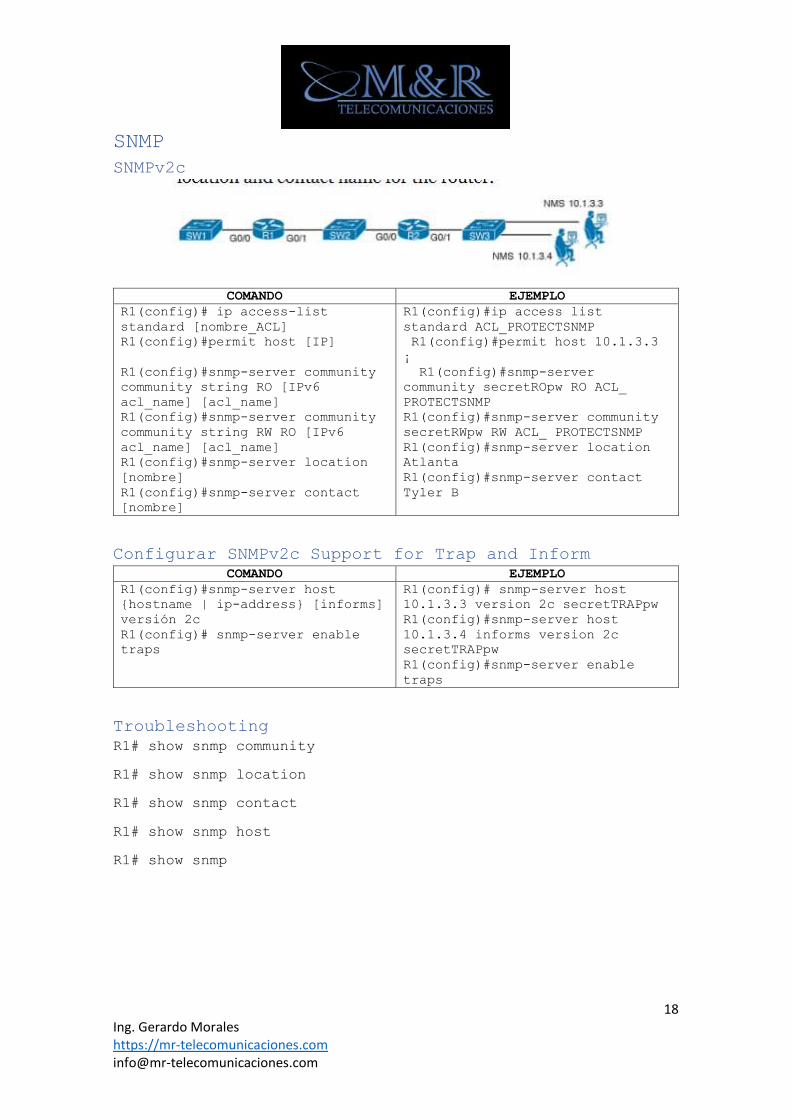
SNMP
SNMPv2c
COMANDO EJEMPLO
R1(config)# ip access-list
standard [nombre_ACL]
R1(config)#permit host [IP]
R1(config)#snmp-server community
community string RO [IPv6
acl_name] [acl_name]
R1(config)#snmp-server community
community string RW RO [IPv6
acl_name] [acl_name]
R1(config)#snmp-server location
[nombre]
R1(config)#snmp-server contact
[nombre]
R1(config)#ip access list
standard ACL_PROTECTSNMP
R1(config)#permit host 10.1.3.3
¡
R1(config)#snmp-server
community secretROpw RO ACL_
PROTECTSNMP
R1(config)#snmp-server community
secretRWpw RW ACL_ PROTECTSNMP
R1(config)#snmp-server location
Atlanta
R1(config)#snmp-server contact
Tyler B
Configurar SNMPv2c Support for Trap and Inform
COMANDO EJEMPLO
R1(config)#snmp-server host
{hostname | ip-address} [informs]
versión 2c
R1(config)# snmp-server enable
traps
R1(config)# snmp-server host
10.1.3.3 version 2c secretTRAPpw
R1(config)#snmp-server host
10.1.3.4 informs version 2c
secretTRAPpw
R1(config)#snmp-server enable
traps
Troubleshooting
R1# show snmp community
R1# show snmp location
R1# show snmp contact
R1# show snmp host
R1# show snmp
19 Ing. Gerardo Morales https://mr-telecomunicaciones.com [email protected]
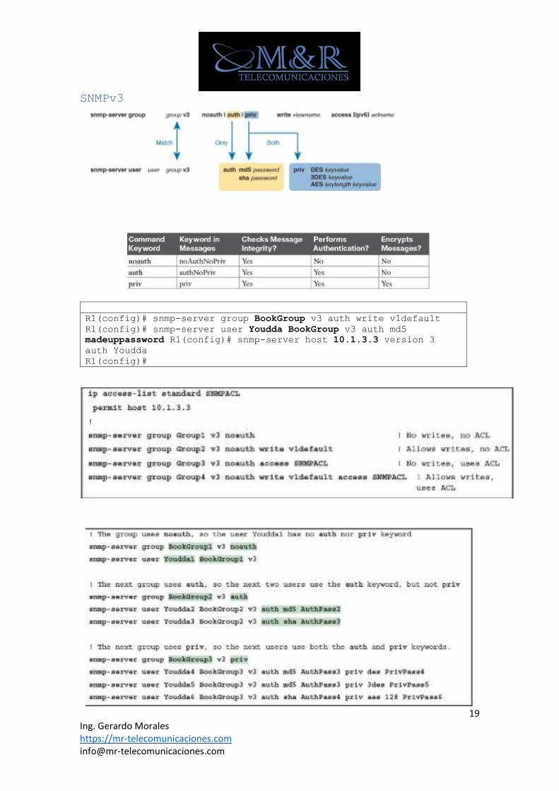
SNMPv3
R1(config)# snmp-server group BookGroup v3 auth write v1default
R1(config)# snmp-server user Youdda BookGroup v3 auth md5
madeuppassword R1(config)# snmp-server host 10.1.3.3 version 3
auth Youdda
R1(config)#
20 Ing. Gerardo Morales https://mr-telecomunicaciones.com [email protected]
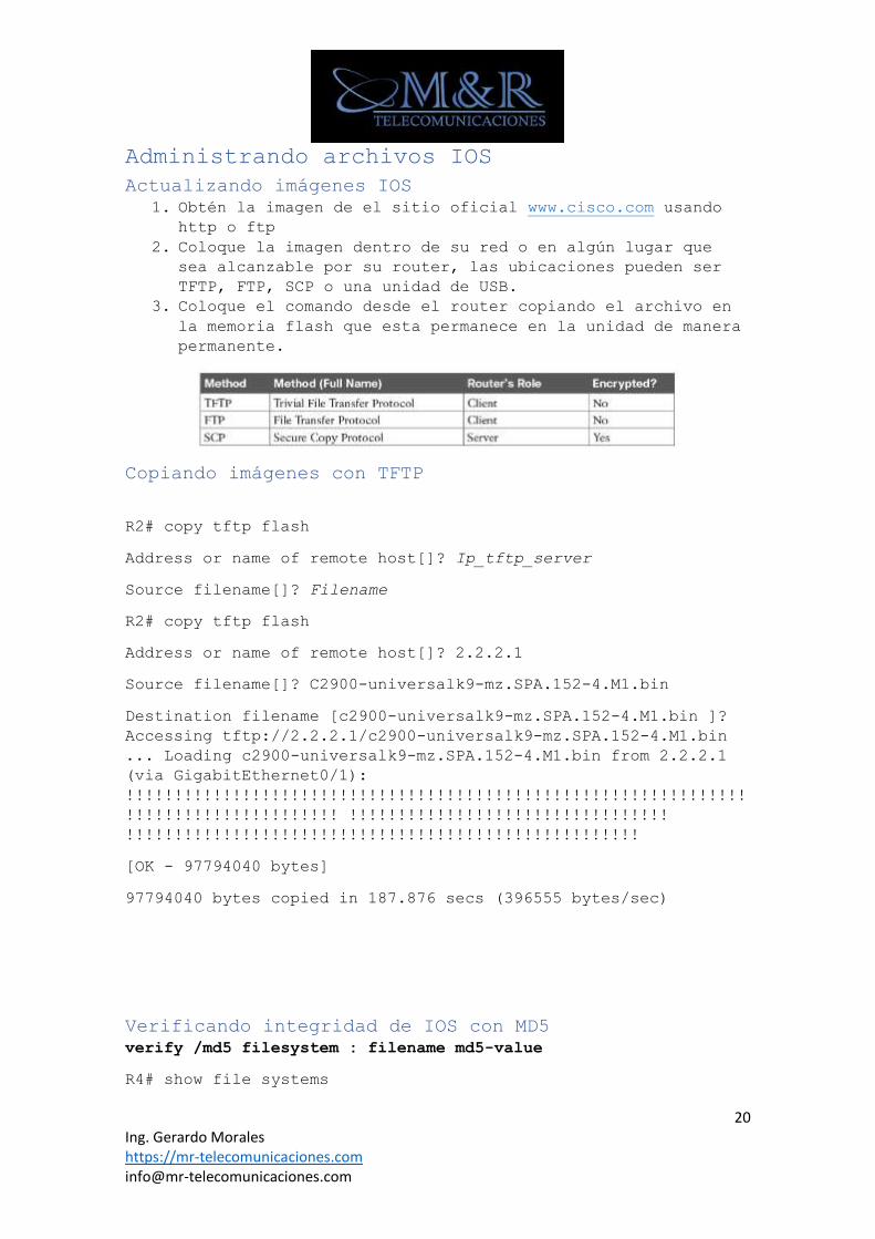
Administrando archivos IOS
Actualizando imágenes IOS
1. Obtén la imagen de el sitio oficial www.cisco.com usando
http o ftp
2. Coloque la imagen dentro de su red o en algún lugar que
sea alcanzable por su router, las ubicaciones pueden ser
TFTP, FTP, SCP o una unidad de USB.
3. Coloque el comando desde el router copiando el archivo en
la memoria flash que esta permanece en la unidad de manera
permanente.
Copiando imágenes con TFTP
R2# copy tftp flash
Address or name of remote host[]? Ip_tftp_server
Source filename[]? Filename
R2# copy tftp flash
Address or name of remote host[]? 2.2.2.1
Source filename[]? C2900-universalk9-mz.SPA.152-4.M1.bin
Destination filename [c2900-universalk9-mz.SPA.152-4.M1.bin ]?
Accessing tftp://2.2.2.1/c2900-universalk9-mz.SPA.152-4.M1.bin
... Loading c2900-universalk9-mz.SPA.152-4.M1.bin from 2.2.2.1
(via GigabitEthernet0/1):
!!!!!!!!!!!!!!!!!!!!!!!!!!!!!!!!!!!!!!!!!!!!!!!!!!!!!!!!!!!!!!!!
!!!!!!!!!!!!!!!!!!!!!! !!!!!!!!!!!!!!!!!!!!!!!!!!!!!!!!!
!!!!!!!!!!!!!!!!!!!!!!!!!!!!!!!!!!!!!!!!!!!!!!!!!!!!!
[OK - 97794040 bytes]
97794040 bytes copied in 187.876 secs (396555 bytes/sec)
Verificando integridad de IOS con MD5
verify /md5 filesystem : filename md5-value
R4# show file systems
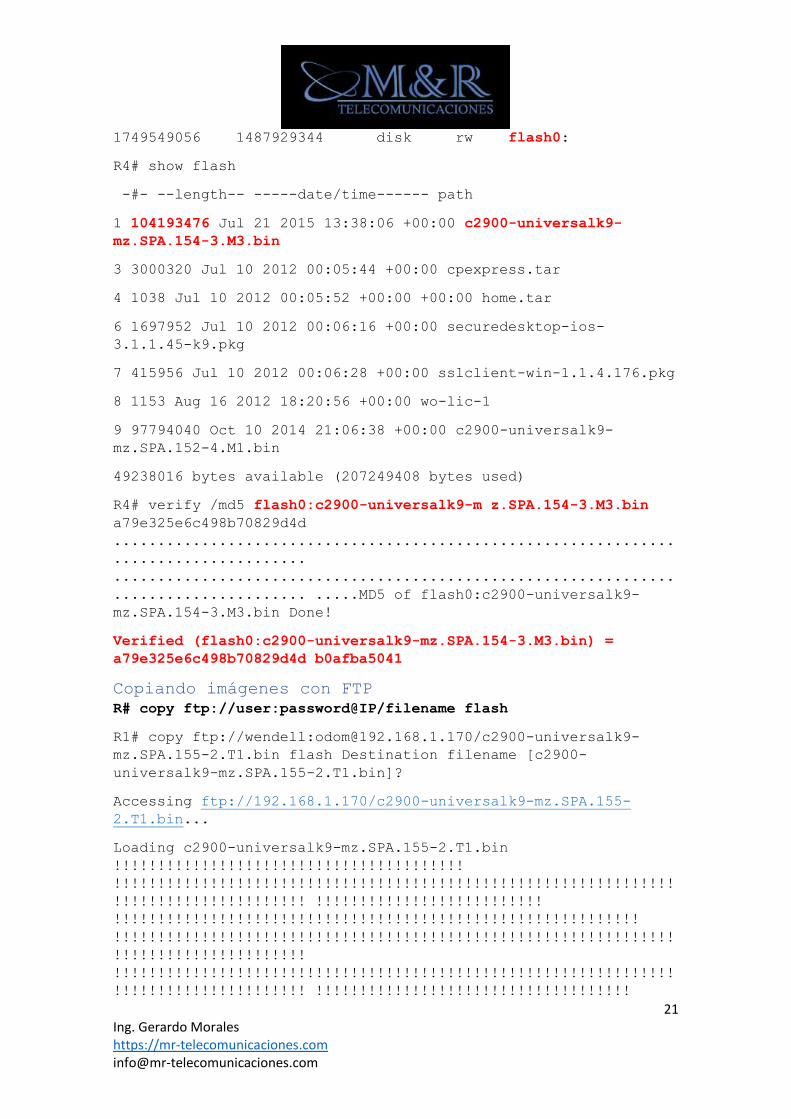
21 Ing. Gerardo Morales https://mr-telecomunicaciones.com [email protected]
1749549056 1487929344 disk rw flash0:
R4# show flash
-#- --length-- -----date/time------ path
1 104193476 Jul 21 2015 13:38:06 +00:00 c2900-universalk9-
mz.SPA.154-3.M3.bin
3 3000320 Jul 10 2012 00:05:44 +00:00 cpexpress.tar
4 1038 Jul 10 2012 00:05:52 +00:00 +00:00 home.tar
6 1697952 Jul 10 2012 00:06:16 +00:00 securedesktop-ios-
3.1.1.45-k9.pkg
7 415956 Jul 10 2012 00:06:28 +00:00 sslclient-win-1.1.4.176.pkg
8 1153 Aug 16 2012 18:20:56 +00:00 wo-lic-1
9 97794040 Oct 10 2014 21:06:38 +00:00 c2900-universalk9-
mz.SPA.152-4.M1.bin
49238016 bytes available (207249408 bytes used)
R4# verify /md5 flash0:c2900-universalk9-m z.SPA.154-3.M3.bin
a79e325e6c498b70829d4d
................................................................
......................
................................................................
...................... .....MD5 of flash0:c2900-universalk9-
mz.SPA.154-3.M3.bin Done!
Verified (flash0:c2900-universalk9-mz.SPA.154-3.M3.bin) =
a79e325e6c498b70829d4d b0afba5041
Copiando imágenes con FTP
R# copy ftp://user:password@IP/filename flash
R1# copy ftp://wendell:[email protected]/c2900-universalk9-
mz.SPA.155-2.T1.bin flash Destination filename [c2900-
universalk9-mz.SPA.155-2.T1.bin]?
Accessing ftp://192.168.1.170/c2900-universalk9-mz.SPA.155-
2.T1.bin...
Loading c2900-universalk9-mz.SPA.155-2.T1.bin
!!!!!!!!!!!!!!!!!!!!!!!!!!!!!!!!!!!!!!!!
!!!!!!!!!!!!!!!!!!!!!!!!!!!!!!!!!!!!!!!!!!!!!!!!!!!!!!!!!!!!!!!!
!!!!!!!!!!!!!!!!!!!!!! !!!!!!!!!!!!!!!!!!!!!!!!!!
!!!!!!!!!!!!!!!!!!!!!!!!!!!!!!!!!!!!!!!!!!!!!!!!!!!!!!!!!!!!
!!!!!!!!!!!!!!!!!!!!!!!!!!!!!!!!!!!!!!!!!!!!!!!!!!!!!!!!!!!!!!!!
!!!!!!!!!!!!!!!!!!!!!!
!!!!!!!!!!!!!!!!!!!!!!!!!!!!!!!!!!!!!!!!!!!!!!!!!!!!!!!!!!!!!!!!
!!!!!!!!!!!!!!!!!!!!!! !!!!!!!!!!!!!!!!!!!!!!!!!!!!!!!!!!!!
22 Ing. Gerardo Morales https://mr-telecomunicaciones.com [email protected]
Copiando imágenes con SCP
Para que SCP funcione en un enrutador, primero el enrutador
necesita admitir inicio de sesión SSH de manera normal.
1. Enable
2. configure terminal
3. aaa new-model
4. aaa authentication login {default | list-name} method1 [
method2... ]
5. aaa authorization {network | exec | commands level |
reverse-access | configuration} {default | list-name}
[method1 [ method2... ]]
6. username name [privilege level] password encryption-type
encrypted-password
7. ip scp server enable
8. exit
Ejemplo 1
Device> enable
Device# configure terminal
Device(config)# aaa new-model
Device(config)# aaa authentication login default group tacacs+
Device(config)# aaa authorization exec default group tacacs+
Device(config)# username superuser privilege 2 password 0
superpassword
Device(config)# ip scp server enable
Device(config)# exit
Ejemplo 2
Device> enable
Device# configure terminal
Device(config)# username fred privilege 15 password barney
Device(config)# ip scp server enable
Computadora
23 Ing. Gerardo Morales https://mr-telecomunicaciones.com [email protected]
WO-iMac:Desktop wendellodom$ scp c2900-universalk9-mz.SPA.155-
2.T1.bin [email protected]:flash0:c2900-universalk9-
mz.SPA.155-2.T1.bin
Password:
c2900-universalk9-mz.SPA.155-2.T1.bin 100% 102MB 322.8KB/s
Copiar un archivo en una unidad USB
Device# show file systems
- - disk rw usbflash1:
Device # copy running-config usbflash1:temp-copy-of-config
R1# dir usbflash1:
Directory of usbflash1:/
! lines listing other files omitted for brevity.
74 -rw- 3159 Feb 12 2013 22:17:00 +00:00 temp-copy-of-config
7783804928 bytes total (7685111808 bytes free)
Configuración tradicional de backup y restauración con
el comando copy
1. Device# copy running-config tftp
2. Device#copy tftp startup-config
3. Device# reload
Alternativas para la configuración de Backup y la
restauración de manera automática
R1# configure terminal
Enter configuration commands, one per line. End with CNTL/Z.
R1(config)# archive
R1(config-archive)# path ftp://wendell:[email protected]/
R1(config-archive)# time-period 1440
R1(config-archive)# write-memory
R1(config-archive)# ^Z
Borrando Archivos de Configuración
Comandos Antiguos
Device# write erase
Device# erase startup-config
24 Ing. Gerardo Morales https://mr-telecomunicaciones.com [email protected]
Comandos Nuevos
Device# erase nvram:
Nota: no existe un comando en Cisco IOS que borre el contenido
del running-config. Para borrar el archivo de configuración usted
deberá realizar lo siguiente. Borre el archivo de configuración
de inicio, luego recargue el enrutador para que el mismo cargue
un archivo de configuración en el arranque vacío.
Troubleshooting
Device# show flash
Device# show file systems
Device# dir filesystem:
Device# dir filesystem:directory
Device# show archive
Administración de las licencias de IOS
Activación manual de licencias IOS
1. Ve a la pagina www.cisco.com/go/licence
2. Colocar el siguiente comando R1# show license udi
3. En el portal de la pagina web ingrese el PAK (producto
authorizathion key)
4. Cisco le enviara la licencia a su mail, con el enlace para
su descarga.
5. Copie la licencia en una USB para equipos nuevos o utilice
tftp, ftp o scp.
6. Coloque el siguiente comando device# licence install url
7. Coloque el comando reload.
Ejemplo
R1# show license
Index 1 Feature: ipbasek9
Period left: Life time
License Type: Permanent
License State: Active, In Use
License Count: Non-Counted
License Priority: Medium
Index 2 Feature: securityk9
Period left: Not Activated
Period Used: 0 minute 0 second
25 Ing. Gerardo Morales https://mr-telecomunicaciones.com [email protected]
License Type: EvalRightToUse
License State: Not in Use, EULA not accepted
License Count: Non-Counted License Priority: None
Index 3 Feature: uck9
Period left: Not Activated
Period Used: 0 minute 0 second
License Type: EvalRightToUse
License State: Not in Use, EULA not accepted
License Count: Non-Counted
License Priority: None
Index 4 Feature: datak9
Period left: Not Activated
Period Used: 0 minute 0 second
License Type: Permanent
License State: Active, Not in Use
License Count: Non-Counted
License Priority: Medium ! Lines omitted for brevity; 8 more
feature licenses available
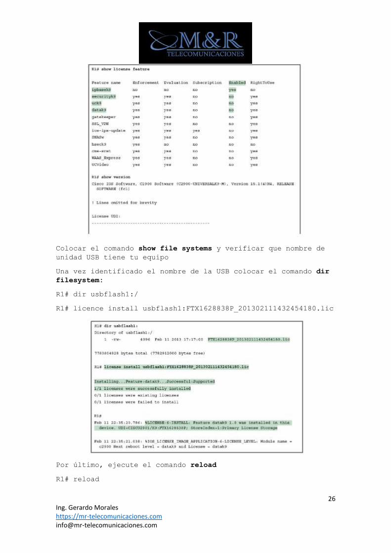
Los comandos show licence feature enumera una lista de salida,
con la columna habilitado a la derecha que muestre el lado
actual.
26 Ing. Gerardo Morales https://mr-telecomunicaciones.com [email protected]
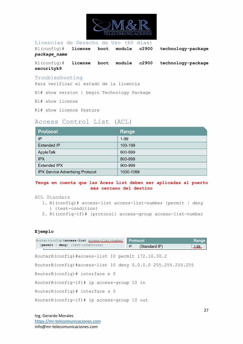
Colocar el comando show file systems y verificar que nombre de
unidad USB tiene tu equipo
Una vez identificado el nombre de la USB colocar el comando dir
filesystem:
R1# dir usbflash1:/
R1# licence install usbflash1:FTX1628838P_201302111432454180.lic
Por último, ejecute el comando reload
R1# reload
27 Ing. Gerardo Morales https://mr-telecomunicaciones.com [email protected]
Licencias de Derecho de Uso (60 días)
R1(config)# license boot module c2900 technology-package
package_name
R1(config)# license boot module c2900 technology-package
securityk9
Troubleshooting
Para verificar el estado de la licencia
R1# show version | begin Technology Package
R1# show license
R1# show licence feature
Access Control List (ACL)
Tenga en cuenta que las Acess List deben ser aplicadas al puerto
más cercano del destino
ACL Standars
1. R1(config)# access-list access-list-number {permit | deny
} {test-condition}
2. R1(config-if)# {protocol} access-group access-list-number
Ejemplo
RouterB(config)#access-list 10 permit 172.16.30.2
RouterB(config)#access-list 10 deny 0.0.0.0 255.255.255.255
RouterB(config)# interface e 0
RouterB(config-if)# ip access-group 10 in
RouterB(config)# interface s 0
RouterB(config-if)# ip access-group 10 out
28 Ing. Gerardo Morales https://mr-telecomunicaciones.com [email protected]
RouterB(config)# interface s 1
RouterB(config-if)# ip access-group 10 out
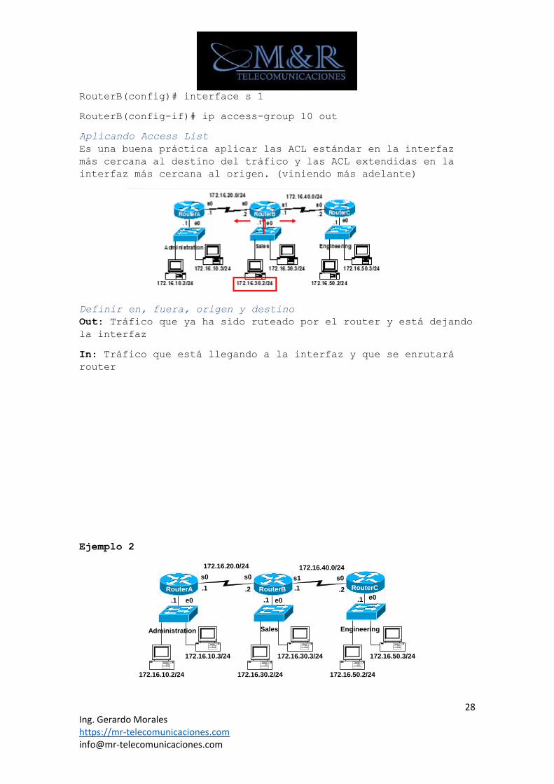
Aplicando Access List
Es una buena práctica aplicar las ACL estándar en la interfaz
más cercana al destino del tráfico y las ACL extendidas en la
interfaz más cercana al origen. (viniendo más adelante)
Definir en, fuera, origen y destino
Out: Tráfico que ya ha sido ruteado por el router y está dejando
la interfaz
In: Tráfico que está llegando a la interfaz y que se enrutará
router
Ejemplo 2
172.16.10.2/24
172.16.10.3/24
172.16.30.2/24
172.16.30.3/24
172.16.50.2/24
172.16.50.3/24
172.16.20.0/24 172.16.40.0/24
e0 e0 e0.1 .1 .1
.1 .1.2 .2
s0 s0 s1 s0
RouterA RouterB RouterC
Administration Sales Engineering
29 Ing. Gerardo Morales https://mr-telecomunicaciones.com [email protected]
1. Permitir sólo los hosts 172.16.30.2, 172.16.30.3,
172.16.30.4, 172.16.30.5 de salir de la red de ventas.
2. Deniegue a todos los demás hosts de la red de ventas que
abandonen la red 172.16.30.0/24.
RouterB(config)#access-list 10 permit 172.16.30.2
RouterB(config)#access-list 10 permit 172.16.30.3
RouterB(config)#access-list 10 permit 172.16.30.4
RouterB(config)#access-list 10 permit 172.16.30.5
Implicit “deny any” -do not need to add this, discussed later
RouterB(config)#access-list 10 deny 0.0.0.0 255.255.255.255
RouterB(config)# interface e 0
RouterB(config-if)# ip access-group 10 in
Borrar Access List
RouterB(config)#no access-list 10
RouterB(config)# interface e 0
RouterB(config-if)# no ip access-group 10 in
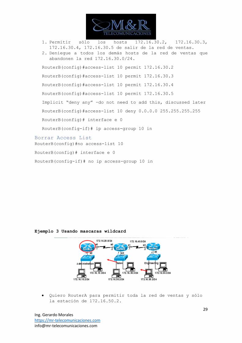
Ejemplo 3 Usando mascaras wildcard
• Quiero RouterA para permitir toda la red de ventas y sólo
la estación de 172.16.50.2.
30 Ing. Gerardo Morales https://mr-telecomunicaciones.com [email protected]
• Negar cualquier otro tráfico de entrar en la red
administrativa.
RouterA(config)#access-list 11 permit 172.16.30.0 0.0.0.255
RouterA(config)#access-list 11 permit 172.16.50.2 0.0.0.0
RouterA(config)# interface e 0
RouterA(config-if)#ip access-group 11 out
Usando la palabra ANY
RouterA(config)#access-list 11 deny 0.0.0.0 255.255.255.255
Or
RouterA(config)#access-list 11 deny any
Opción de Host
RouterB(config)#access-list 10 permit 192.168.1.100 0.0.0.0
RouterB(config)#access-list 10 permit host 192.168.1.100
172.16.10.100 0.0.0.0 replaced by host 172.16.10.100
192.168.1.100 0.0.0.0 replaced by host 192.168.1.100
Rangos de Access List
El administrador desea utilizar bits de enmascaramiento de
comodín de IP para permitir, coincidir con las subredes
172.30.16.0 a 172.30.31.0.
access-list 20 permit 172.30.16.0 0.0.15.255
Enlazar Subredes 172.30.16.0 a 172.30.31.0
access-list 20 permit 172.30.16.0 0.0.15.255
32 Ing. Gerardo Morales https://mr-telecomunicaciones.com [email protected]
Ejemplo
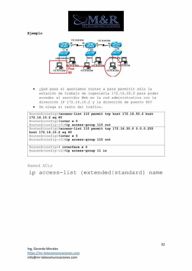
• ¿Qué pasa si queríamos router a para permitir sólo la
estación de trabajo de ingeniería 172.16.50.2 para poder
acceder al servidor Web en la red administrativa con la
dirección IP 172.16.10.2 y la dirección de puerto 80?
• Se niega el resto del tráfico.
RouterA(config)#access-list 110 permit tcp host 172.16.50.2 host
172.16.10.2 eq 80
RouterA(config)#inter e 0
RouterA(config-if)#ip access-group 110 out
RouterA(config)#access-list 110 permit tcp 172.16.30.0 0.0.0.255
host 172.16.10.2 eq 80
RouterA(config)#inter e 0
RouterA(config-if)#ip access-group 110 out
RouterA(config)# interface e 0
RouterA(config-if)#ip access-group 11 in
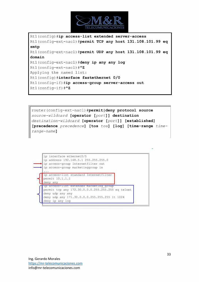
Named ACLs
33 Ing. Gerardo Morales https://mr-telecomunicaciones.com [email protected]
34 Ing. Gerardo Morales https://mr-telecomunicaciones.com [email protected]
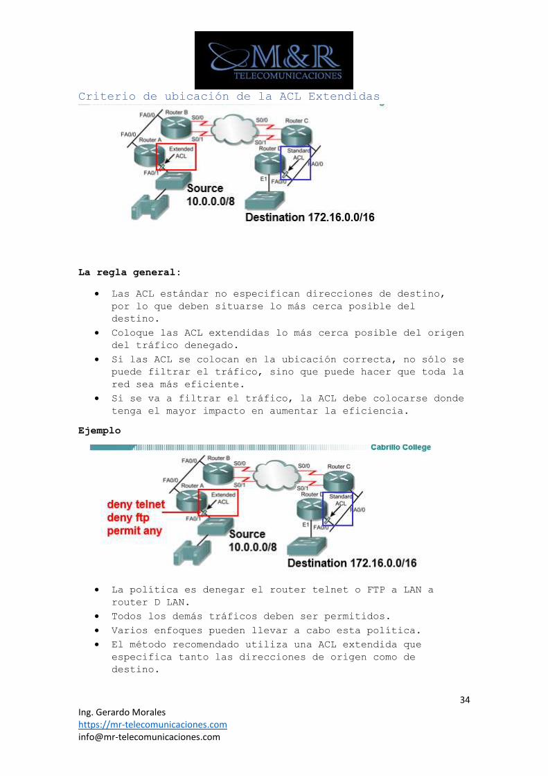
Criterio de ubicación de la ACL Extendidas
La regla general:
• Las ACL estándar no especifican direcciones de destino,
por lo que deben situarse lo más cerca posible del
destino.
• Coloque las ACL extendidas lo más cerca posible del origen
del tráfico denegado.
• Si las ACL se colocan en la ubicación correcta, no sólo se
puede filtrar el tráfico, sino que puede hacer que toda la
red sea más eficiente.
• Si se va a filtrar el tráfico, la ACL debe colocarse donde
tenga el mayor impacto en aumentar la eficiencia.
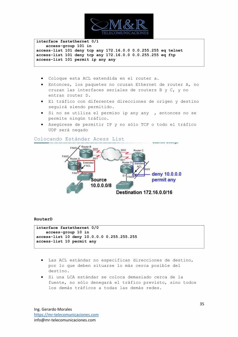
Ejemplo
• La política es denegar el router telnet o FTP a LAN a
router D LAN.
• Todos los demás tráficos deben ser permitidos.
• Varios enfoques pueden llevar a cabo esta política.
• El método recomendado utiliza una ACL extendida que
especifica tanto las direcciones de origen como de
destino.
35 Ing. Gerardo Morales https://mr-telecomunicaciones.com [email protected]
interface fastethernet 0/1
access-group 101 in
access-list 101 deny tcp any 172.16.0.0 0.0.255.255 eq telnet
access-list 101 deny tcp any 172.16.0.0 0.0.255.255 eq ftp
access-list 101 permit ip any any
• Coloque esta ACL extendida en el router a.
• Entonces, los paquetes no cruzan Ethernet de router A, no
cruzan las interfaces seriales de routers B y C, y no
entran router D.
• El tráfico con diferentes direcciones de origen y destino
seguirá siendo permitido.
• Si no se utiliza el permiso ip any any , entonces no se
permite ningún tráfico.
• Asegúrese de permitir IP y no sólo TCP o todo el tráfico
UDP será negado
Colocando Estándar Acess List
RouterD
interface fastethernet 0/0
access-group 10 in
access-list 10 deny 10.0.0.0 0.255.255.255
access-list 10 permit any
• Las ACL estándar no especifican direcciones de destino,
por lo que deben situarse lo más cerca posible del
destino.
• Si una LCA estándar se coloca demasiado cerca de la
fuente, no sólo denegará el tráfico previsto, sino todos
los demás tráficos a todas las demás redes.
36 Ing. Gerardo Morales https://mr-telecomunicaciones.com [email protected]
• Es mejor utilizar listas de acceso extendido, y colocarlas
cerca de la fuente, ya que este tráfico se desplazará
hasta el router antes de ser negado.
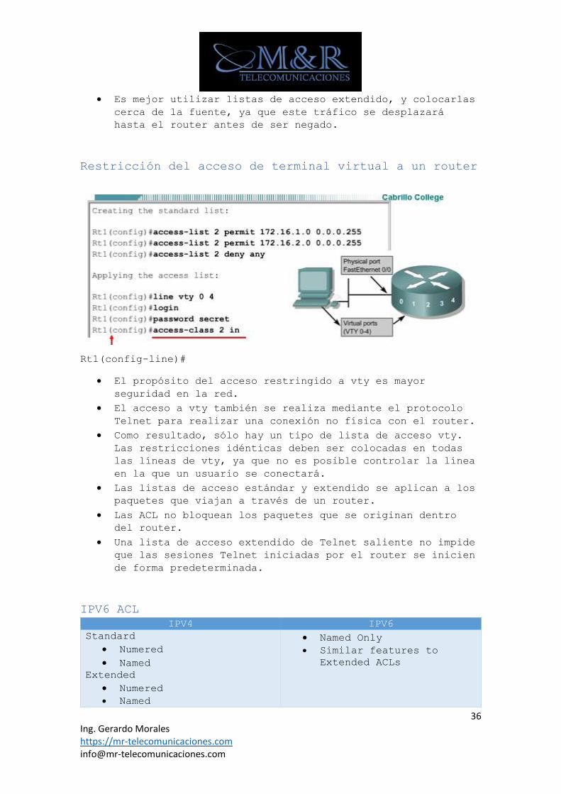
Restricción del acceso de terminal virtual a un router
Rt1(config-line)#
• El propósito del acceso restringido a vty es mayor
seguridad en la red.
• El acceso a vty también se realiza mediante el protocolo
Telnet para realizar una conexión no física con el router.
• Como resultado, sólo hay un tipo de lista de acceso vty.
Las restricciones idénticas deben ser colocadas en todas
las líneas de vty, ya que no es posible controlar la línea
en la que un usuario se conectará.
• Las listas de acceso estándar y extendido se aplican a los
paquetes que viajan a través de un router.
• Las ACL no bloquean los paquetes que se originan dentro
del router.
• Una lista de acceso extendido de Telnet saliente no impide
que las sesiones Telnet iniciadas por el router se inicien
de forma predeterminada.
IPV6 ACL
IPV4 IPV6
Standard
• Numered
• Named
Extended
• Numered
• Named
• Named Only
• Similar features to
Extended ACLs
37 Ing. Gerardo Morales https://mr-telecomunicaciones.com [email protected]
IPv4 - ip access-group IPv6 - ipv6 traffic-
filter
Wildcard Mask No Wildcard Masks -
Instead, the prefix-
length is used
permit icmp any any nd-na
permit icmp any any nd-ns
38 Ing. Gerardo Morales https://mr-telecomunicaciones.com [email protected]
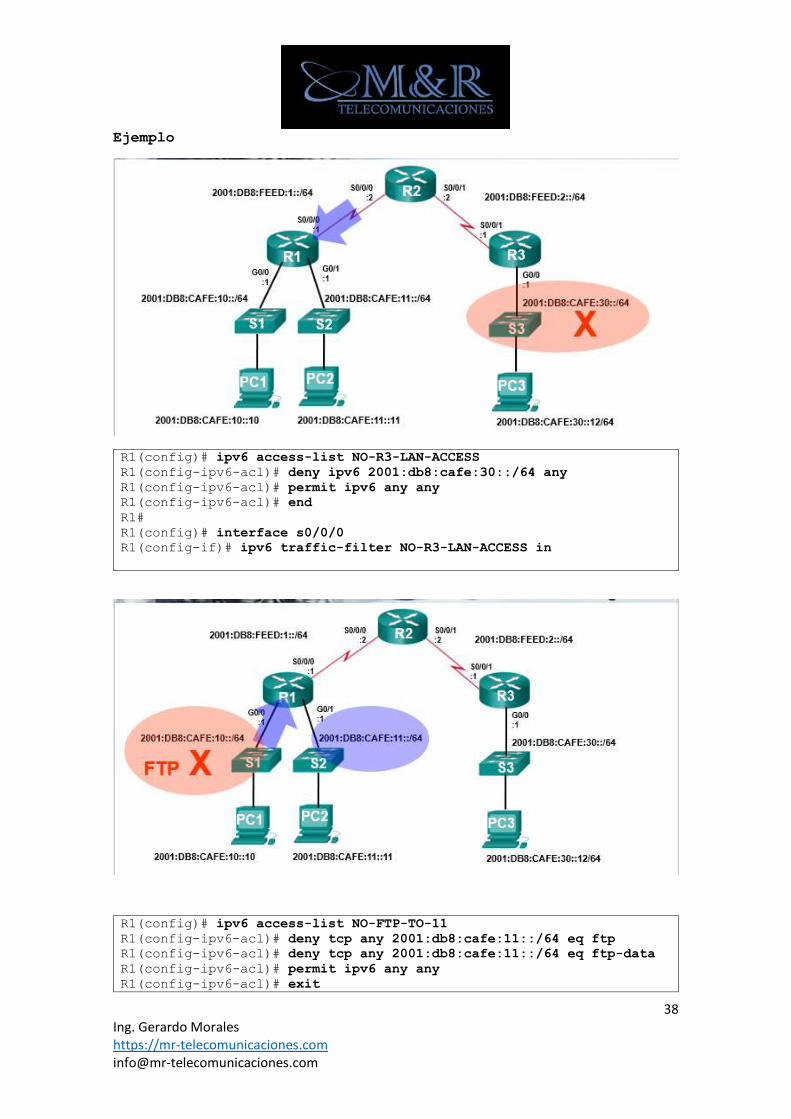
Ejemplo
R1(config)# ipv6 access-list NO-R3-LAN-ACCESS
R1(config-ipv6-acl)# deny ipv6 2001:db8:cafe:30::/64 any
R1(config-ipv6-acl)# permit ipv6 any any
R1(config-ipv6-acl)# end
R1#
R1(config)# interface s0/0/0
R1(config-if)# ipv6 traffic-filter NO-R3-LAN-ACCESS in
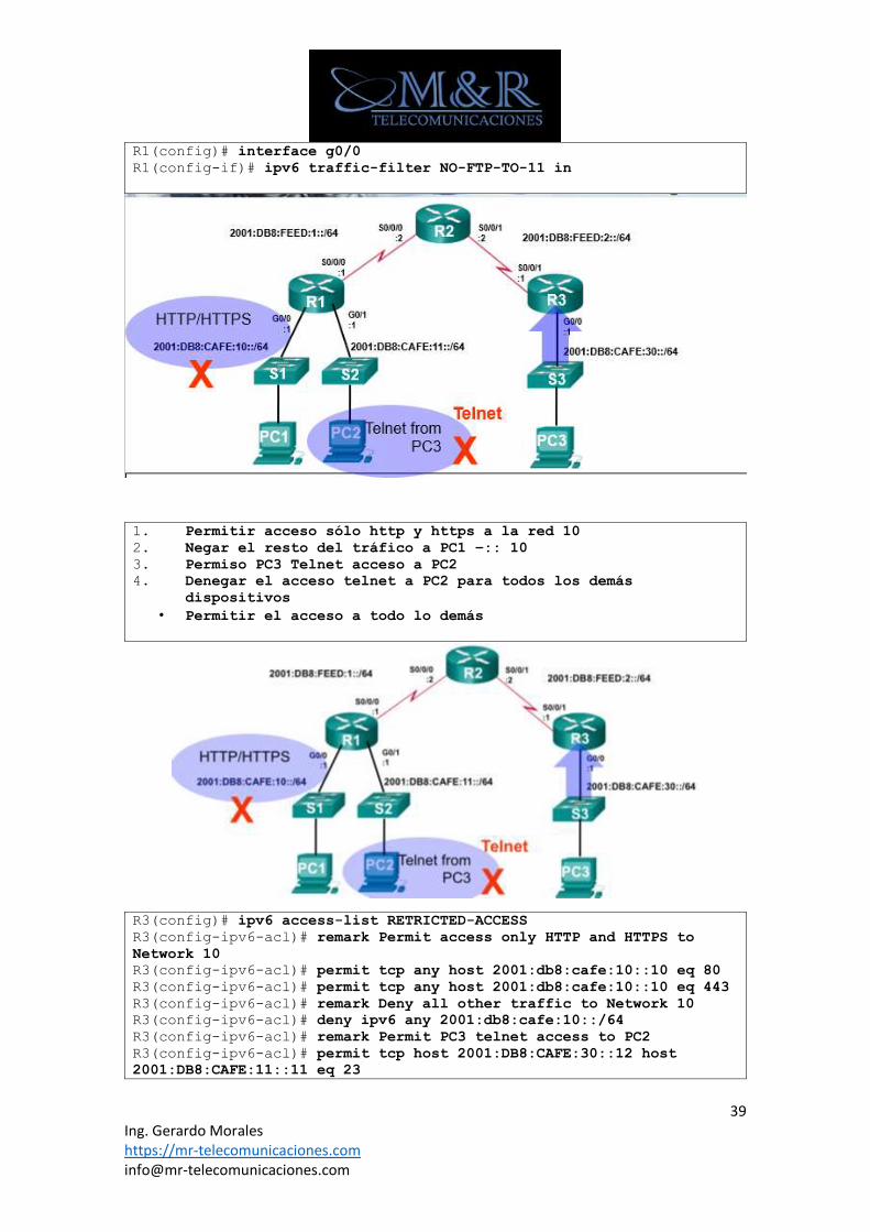
R1(config)# ipv6 access-list NO-FTP-TO-11
R1(config-ipv6-acl)# deny tcp any 2001:db8:cafe:11::/64 eq ftp
R1(config-ipv6-acl)# deny tcp any 2001:db8:cafe:11::/64 eq ftp-data
R1(config-ipv6-acl)# permit ipv6 any any
R1(config-ipv6-acl)# exit
39 Ing. Gerardo Morales https://mr-telecomunicaciones.com [email protected]
R1(config)# interface g0/0
R1(config-if)# ipv6 traffic-filter NO-FTP-TO-11 in
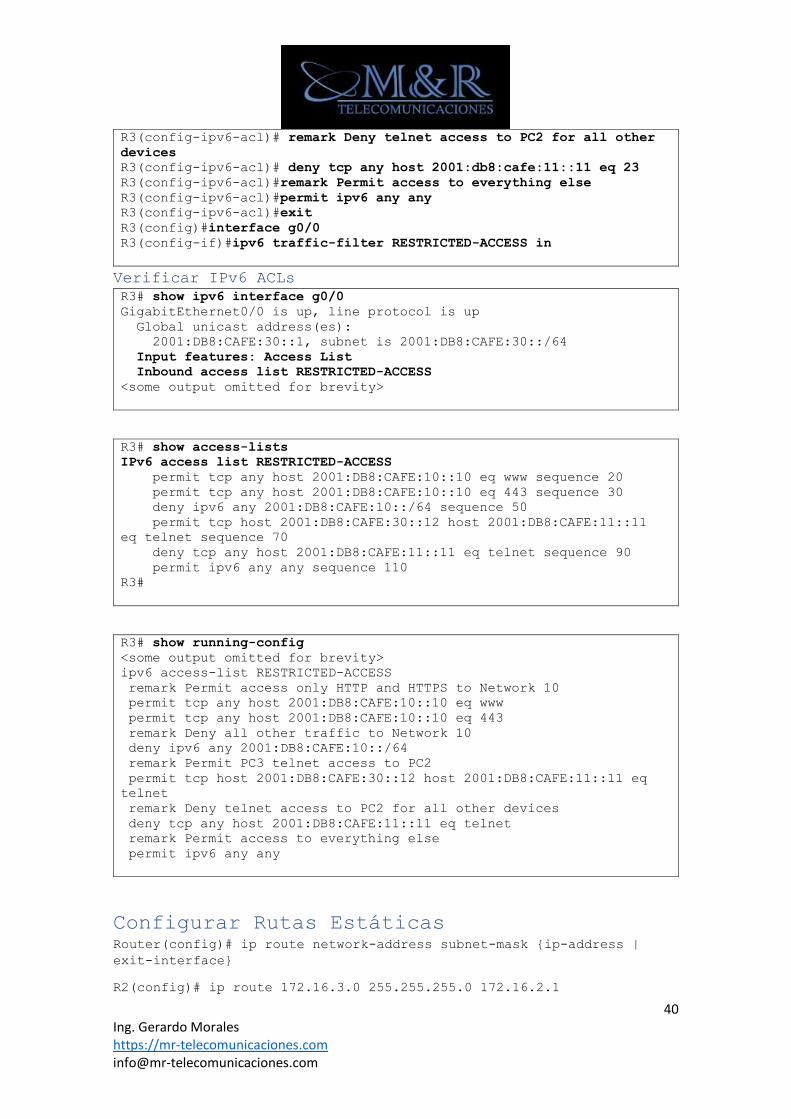
1. Permitir acceso sólo http y https a la red 10
2. Negar el resto del tráfico a PC1 –:: 10
3. Permiso PC3 Telnet acceso a PC2
4. Denegar el acceso telnet a PC2 para todos los demás
dispositivos
• Permitir el acceso a todo lo demás
R3(config)# ipv6 access-list RETRICTED-ACCESS
R3(config-ipv6-acl)# remark Permit access only HTTP and HTTPS to
Network 10
R3(config-ipv6-acl)# permit tcp any host 2001:db8:cafe:10::10 eq 80
R3(config-ipv6-acl)# permit tcp any host 2001:db8:cafe:10::10 eq 443
R3(config-ipv6-acl)# remark Deny all other traffic to Network 10
R3(config-ipv6-acl)# deny ipv6 any 2001:db8:cafe:10::/64
R3(config-ipv6-acl)# remark Permit PC3 telnet access to PC2
R3(config-ipv6-acl)# permit tcp host 2001:DB8:CAFE:30::12 host
2001:DB8:CAFE:11::11 eq 23
40 Ing. Gerardo Morales https://mr-telecomunicaciones.com [email protected]
R3(config-ipv6-acl)# remark Deny telnet access to PC2 for all other
devices
R3(config-ipv6-acl)# deny tcp any host 2001:db8:cafe:11::11 eq 23
R3(config-ipv6-acl)#remark Permit access to everything else
R3(config-ipv6-acl)#permit ipv6 any any
R3(config-ipv6-acl)#exit
R3(config)#interface g0/0
R3(config-if)#ipv6 traffic-filter RESTRICTED-ACCESS in
Verificar IPv6 ACLs
R3# show ipv6 interface g0/0
GigabitEthernet0/0 is up, line protocol is up
Global unicast address(es):
2001:DB8:CAFE:30::1, subnet is 2001:DB8:CAFE:30::/64
Input features: Access List
Inbound access list RESTRICTED-ACCESS
<some output omitted for brevity>
R3# show access-lists
IPv6 access list RESTRICTED-ACCESS
permit tcp any host 2001:DB8:CAFE:10::10 eq www sequence 20
permit tcp any host 2001:DB8:CAFE:10::10 eq 443 sequence 30
deny ipv6 any 2001:DB8:CAFE:10::/64 sequence 50
permit tcp host 2001:DB8:CAFE:30::12 host 2001:DB8:CAFE:11::11
eq telnet sequence 70
deny tcp any host 2001:DB8:CAFE:11::11 eq telnet sequence 90
permit ipv6 any any sequence 110
R3#
R3# show running-config
<some output omitted for brevity>
ipv6 access-list RESTRICTED-ACCESS
remark Permit access only HTTP and HTTPS to Network 10
permit tcp any host 2001:DB8:CAFE:10::10 eq www
permit tcp any host 2001:DB8:CAFE:10::10 eq 443
remark Deny all other traffic to Network 10
deny ipv6 any 2001:DB8:CAFE:10::/64
remark Permit PC3 telnet access to PC2
permit tcp host 2001:DB8:CAFE:30::12 host 2001:DB8:CAFE:11::11 eq
telnet
remark Deny telnet access to PC2 for all other devices
deny tcp any host 2001:DB8:CAFE:11::11 eq telnet
remark Permit access to everything else
permit ipv6 any any
Configurar Rutas Estáticas Router(config)# ip route network-address subnet-mask {ip-address |
exit-interface}
R2(config)# ip route 172.16.3.0 255.255.255.0 172.16.2.1
41 Ing. Gerardo Morales https://mr-telecomunicaciones.com [email protected]
Borrar rutas estáticas
R2(config)# no ip route 172.16.3.0 255.255.255.0 172.16.2.1
Configurar rutas por defecto Router(config)# ip route 0.0.0.0 0.0.0.0 [exit-interface | ip-address
]
R1(config)# ip route 0.0.0.0 0.0.0.0 serial 0/0/0
Debug
Uso de enrutamiento de IP de depuración
R2# debug ip routing
R2# undebug all
R2# undebug ip routing
Protocolos de Enrutamiento
Classfull
• RIP
• IGRP
Classless
• RIP v2
• EIGRP
• OSPF v2
• IS-IS
IPv6
• RIPng
• EIGRP for IPv6
• OSPF v3
• IS-IS for IPv6
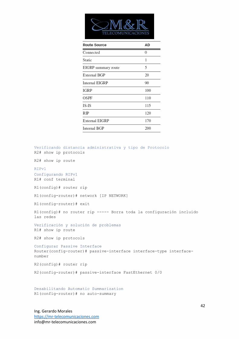
Distancia Administrativa
42 Ing. Gerardo Morales https://mr-telecomunicaciones.com [email protected]
Verificando distancia administrativa y tipo de Protocolo
R2# show ip protocols
R2# show ip route
RIPv1
Configurando RIPv1
R1# conf terminal
R1(config)# router rip
R1(config-router)# network [IP NETWORK]
R1(config-router)# exit
R1(config)# no router rip ----- Borra toda la configuración incluido
las redes
Verificación y solución de problemas
R1# show ip route
R2# show ip protocols
Configurar Passive Interface
Router(config-router)# passive-interface interface-type interface-
number
R2(config)# router rip
R2(config-router)# passive-interface FastEthernet 0/0
Desabilitando Automatic Summarization
R1(config-router)# no auto-summary
43 Ing. Gerardo Morales https://mr-telecomunicaciones.com [email protected]
Configurar Default-Information Originate
R2(config)# router rip
R2(config-router)# default-information originate
R2(config-router)# end
RIPv2
Configurando RIPv2
R1# conf terminal
R1(config)# router rip
R1(config-router)# version 2
R1(config-router)# network [IP NETWORK]
R1(config-router)# exit
R1(config)# no router rip ----- Borra toda la configuración incluido
las redes
Verificación y solución de problemas
R1# show ip route
R2# show ip protocols
Desabilitando Automatic Summarization
R1(config-router)# no auto-summary
Configurar Default-Information Originate
R2(config)# router rip
R2(config-router)# default-information originate
R2(config-router)# end
Configurar Passive Interface
Router(config-router)# passive-interface interface-type interface-
number
R2(config)# router rip
R2(config-router)# passive-interface FastEthernet 0/0
Verificando actualizaciones
R2# debug ip rip
RIP: sending v2 update to 224.0.0.9 via Serial0/0/0 (209.165.200.229)
EIGRP (Distance Vector Protocol)
44 Ing. Gerardo Morales https://mr-telecomunicaciones.com [email protected]
Enabling EIGRP Routing
Router(config)# router eigrp AS number (Must be the same on all
routers)
Router(config-router)# network network-address [wildcard mask]
EIGRP Interface commands
Router(config-if)# ip summary-address eigrp as-number network-
address mask
• RTC(config-if)#ip summary-address eigrp 2446 2.1.0.0 255.255.0.0
Router(config-if)# no auto-summary
1. auto-Resumen encendido por defecto. EIGRP resume
automaticallyentre límites de clase. Debe ser utilizado para
VLSM.
Router(config-if)#bandwidth kilobits
• Configures the bandwidth used by routing metrics on the outgoing
interface.
Router(config-if)#ip bandwidth-percent eigrp as-number bandwidth-
percentage
1. De forma predeterminada, EIGRP se establece para utilizar sólo
hasta el 50% del ancho de banda de una interfaz para
intercambiar información de enrutamiento.
Router(config-router)#eigrp log-neighbor-changes
1. Este comando permite registrar los cambios de adyacencia del
vecino para monitorear la estabilidad del sistema de
enrutamiento y para ayudar a detectar problemas.
RTA(config-router)# variance number
1. La Varianza comando instruye al router a incluir rutas con una
métrica menor o igual a n veces la ruta métrica mínima para ese
destino, donde n es el número especificado por el comando
varianza.
Miscellaneous
Router(config-router)# default-metric 56 100 255 10 1500 {k
values)
Show commands
Router# show ip eigrp neighbors {muestra los vecinos}
Router# show ip eigrp topology
Router# show ip eigrp topology [network]
Router# show ip eigrp topology all links
• displays topology, active/passive (well) state, successors
Router# debug eigrp fsm
Router# debug eigrp packet
Comando para verificar si existe algún problema con las
autenticaciones en los paquetes que se intercambian.
45 Ing. Gerardo Morales https://mr-telecomunicaciones.com [email protected]
Router# show ip route eigrp {Rutas EIGRP en la tabla de
enrutamiento}
Router# show ip protocols
• AS number, filtering, redistribution, neighbors, distance
Router# show ip eigrp traffic EIGRP packets sent and received
Redistribution
Example 1: EIGRP y IGRP se redistribuyen automáticamente siempre que
se utilice el mismo identificador de proceso.
Router(config)# router eigrp 44 and Router(config)# router igrp
44
Modificar la métrica EIGRP
Router (config-router) #metric weights tos k1 k2 k3 k4 k5
Configurando Hello Intervals and Hold Times
Hello intervals and hold times no tienen que coincidir con otros
routers EIGRP para establecer adyacentes el rango es desde 1-
65535. Solo OSPF’s Hello y otros temporizadores tienen que
coincidir.
Router(config-if)# ip hello-interval eigrp as-number seconds
Router(config-if)# ip hold-time eigrp as-number seconds
R1(config)# int s0/0/0
R1(config-if)# ip hello-interval eigrp 1 60
R1(config-if)# ip hold-time eigrp 1 180
Troubleshooting
1. ¿Qué se debe hacer si no estas las tablas de los neighbors?
a. Compruebe las interfaces locales para asegurarse de que se
activa con el comando show ip interface brief
b. Tratar de hacer ping a la dirección del neighbors
2. ¿Qué sucede si hay PING exitoso y el router no puede visualizar
al router vecino?
a. Verificar si ambos router están en el mismo EIGRP process
ID con el comando show ip eigrp neighbors
b. Verificar si no existen passive-interface con el comando
show ip protocols
c. Verificar si es que los pesos de las métricas se
encuentran establecidos por defecto con los valores K1=1,
K2=0, K3=1, K4=0, K5=0 con el comando show ip protocols
d. Verificar si se está realizando un auto-summary, si es el
caso deshabilitar con el comando no auto-summary.
3. ¿Como que comando se encuentra Successor y Feasible Successor?
a. El comando que se debe aplicar es show ip eigrp topology
46 Ing. Gerardo Morales https://mr-telecomunicaciones.com [email protected]
Router# show ip eigrp neighbors {muestra los vecinos}
Router# show ip eigrp topology
Router# show ip eigrp topology [network]
Router# show ip eigrp topology all links
• displays topology, active/passive (well) state, successors
Router# debug eigrp fsm
Router# debug eigrp packet
Dirección muticast
224.0.0.10
OSPF (Link-state routing protocol)
Configuring OSPF Routing
Router(config)# router ospf process-id
Router(config-router)# network network-address wild-card-mask area
area-number
Prioritizing the DR (Router ID)
Sequence (Si se añade un router con mayor prioridad a la red, el Dr y
los Fusileros no cambian.):
1. Priority
Router(config-if)# ip ospf priority number {0 = No DR; 1 =
default; highest = DR}
2. Highest Loopback Address
Router(config)# interface loopback 0
Router(config-if)# ip address ip-address mask
3. Highest Interface Address
Authentication
Router(config-router)# area area-number authentication
Router(config-if)# ip ospf authentication-key password
Show commands
Router# show ip protocols
Router# show ip ospf
Router# show ip ospf interface interface
Router# show ip ospf neighbor
47 Ing. Gerardo Morales https://mr-telecomunicaciones.com [email protected]
Router# show ip ospf neighbor detail
Router# show ip ospf database
Router# show ip ospf adjacencies
Router# show ip ospf border-router
Router# show ip ospf virtual-links
Timers
Router(config-if)# ip ospf hello-interval value
Router(config-if)# ip ospf dead-interval value
Miscellaneous
Router# debug ip ospf
Router# debug ip ospf adj
Router# debug ip ospf events
Referencia rápida: OSPF Routing - Multiple Areas
Backbone Area (Area 0) -
• Interconnects areas
• Accepts all LSAs
• Connects to other AS’s (External Routes)
Stub Area
• Receives summary LSAs (routes) within its own autonomous system
• Does not receive external LSAs (routes)
• Default route injected automatically by ABR
El siguiente comando debe estar en todos los enrutadores de esa área,
tanto ABR como enrutadores internos:
Router(config-router)# area area-id stub
Totally Stubby Area
• Does not receive summary LSAs (routes) within its own autonomous
system
• Does not receive external LSAs (routes)
• Default route injected automatically by ABR
Estos comandos deben estar en el ABR Router:
Router(config-router)# area area-id stub no-summary
El siguiente comando debe estar en todos enrutadores internos en esa
área:
Router(config-router)# area area-id stub
48 Ing. Gerardo Morales https://mr-telecomunicaciones.com [email protected]
NSSA (Not So Stubby Area)
• Receives summary LSAs (routes) within its own autonomous system
• Does not receive external LSAs (routes)
• Allows for redistribution of external routes
• “NSSAs allow external routes to be advertised into the OSPF
autonomous system while retaining the characteristics of a stub
area to the rest of the autonomous system.” - Jeff Doyle
Uno de estos comandos debe estar en el ABR Router:
Router(config-router)# area area-id nssa
Router(config-router)# area area-id nssa default-information-
originate
{Will cause the ASBR to advertise a default route into the
NSSA.}
El siguiente comando debe estar en todos enrutadores internos en esa
área:
Router(config-router)# area area-id nssa
Configuring OSPF Routing
Router(config)# router ospf process-id
Router(config-router)# network network-address wild-card-mask area
area-1-number
Router(config-router)# network network-address wild-card-mask area
area-2-number
{ABR would have multiple area statements.}
49 Ing. Gerardo Morales https://mr-telecomunicaciones.com [email protected]
OSPF Routing - Area Range (Summarization)
On the ABR (Resume las rutas antes de inyectarlas en diferentes
áreas)
Router(config-router)# area area-id range network-address subnet-
mask
{Summarization is off by default}
{Useful for supernetting}
On the ASBR (Resume las rutas externas antes de inyectarlas en el
dominio OSPF.)
Router(config-router)# summary-address network-address subnet-mask
Virtual Links
Router(config-router)# area area-id virtual-link abr-ip-add
{abr-ip-add usually loopback of ABR on remote area 0}
{Virtual links are used to connect discontinuous area 0’s}
Miscellaneous
Router(config-router)# area process-id default-cost metric
Router(config-if)# bandwidth value
Router(config-if)# ip ospf cost value
Troubleshooting Router# clear ip ospf process
Router# show ip protocols
Router# show ip ospf
Router# show ip ospf interface interface
Router# show ip ospf neighbor
Router# show ip ospf neighbor detail
Router# show ip ospf database
Router# show ip ospf adjacencies
Router# show ip ospf border-router
50 Ing. Gerardo Morales https://mr-telecomunicaciones.com [email protected]
Router# show ip ospf virtual-links
IPv6
Comando para habilitar IPv6
R1(config)# ipv6 unicast-routing -- Direccion global unicast
R1(config)# ipv6 enable.- habilita la interfaz IPV6 y genera link-
local address
Configurando direcciones de 128 bits
R1(config)# ipv6 unicast-routing
R1(config)# interface GigabitEthernet 0/0
R1(config-if)# ipv6 address
2001:DB8:1111:1::1/64
R1(config-if)#exit
R1(config)# interface serial0/0/0
R1(config-if)# ipv6 address
2001:0DB8:1111:0002:0000:0000:0000:0001/64
R2(config)# ipv6 unicast-
routing
R2(config)# interface
GigabitEthernet 0/0
R2(config-if)# ipv6
address
2001:DB8:1111:3::2/64
R2(config-if)#exit
R2(config)# interface
serial0/0/1
R1(config-if)# ipv6
address
2001:DB8:1111:2::2/64
Troubleshooting
R1#show ipv6 interface brief
R1# show ipv6 interface GigabitEthernet 0/0
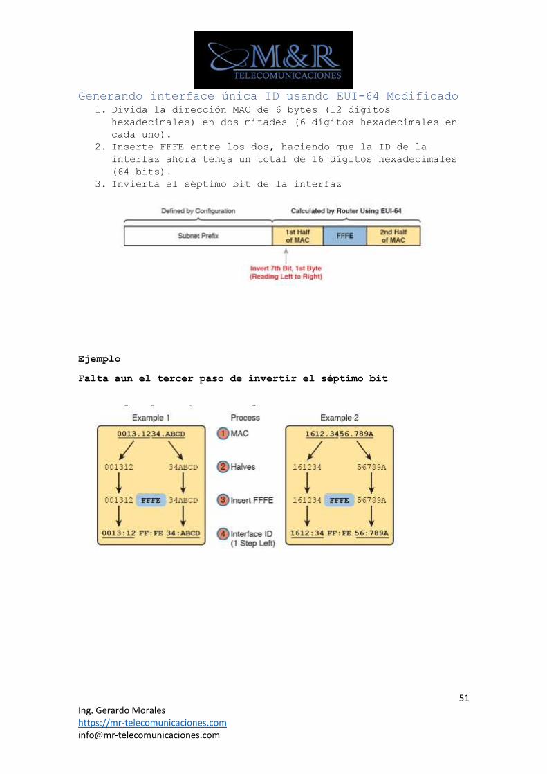
51 Ing. Gerardo Morales https://mr-telecomunicaciones.com [email protected]
Generando interface única ID usando EUI-64 Modificado
1. Divida la dirección MAC de 6 bytes (12 dígitos
hexadecimales) en dos mitades (6 dígitos hexadecimales en
cada uno).
2. Inserte FFFE entre los dos, haciendo que la ID de la
interfaz ahora tenga un total de 16 dígitos hexadecimales
(64 bits).
3. Invierta el séptimo bit de la interfaz
Ejemplo
Falta aun el tercer paso de invertir el séptimo bit
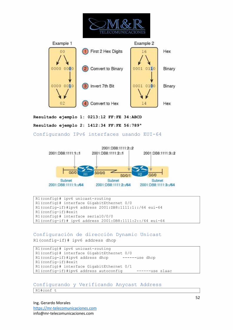
52 Ing. Gerardo Morales https://mr-telecomunicaciones.com [email protected]
Resultado ejemplo 1: 0213:12 FF:FE 34:ABCD
Resultado ejemplo 2: 1412:34 FF:FE 56:789ª
Configurando IPv6 interfaces usando EUI-64
R1(config)# ipv6 unicast-routing
R1(config)# interface GigabitEthernet 0/0
R1(config-if)#ipv6 address 2001:DB8:1111:1::/64 eui-64
R1(config-if)#exit
R1(config)# interface serial0/0/0
R1(config-if)# ipv6 address 2001:DB8:1111:2::/64 eui-64
Configuración de dirección Dynamic Unicast
R1(config-if)# ipv6 address dhcp
R1(config)# ipv6 unicast-routing
R1(config)# interface GigabitEthernet 0/0
R1(config-if)#ipv6 address dhcp ------use dhcp
R1(config-if)#exit
R1(config)# interface GigabitEthernet 0/1
R1(config-if)#ipv6 address autoconfig ------use slaac
Configurando y Verificando Anycast Address
R1#conf t
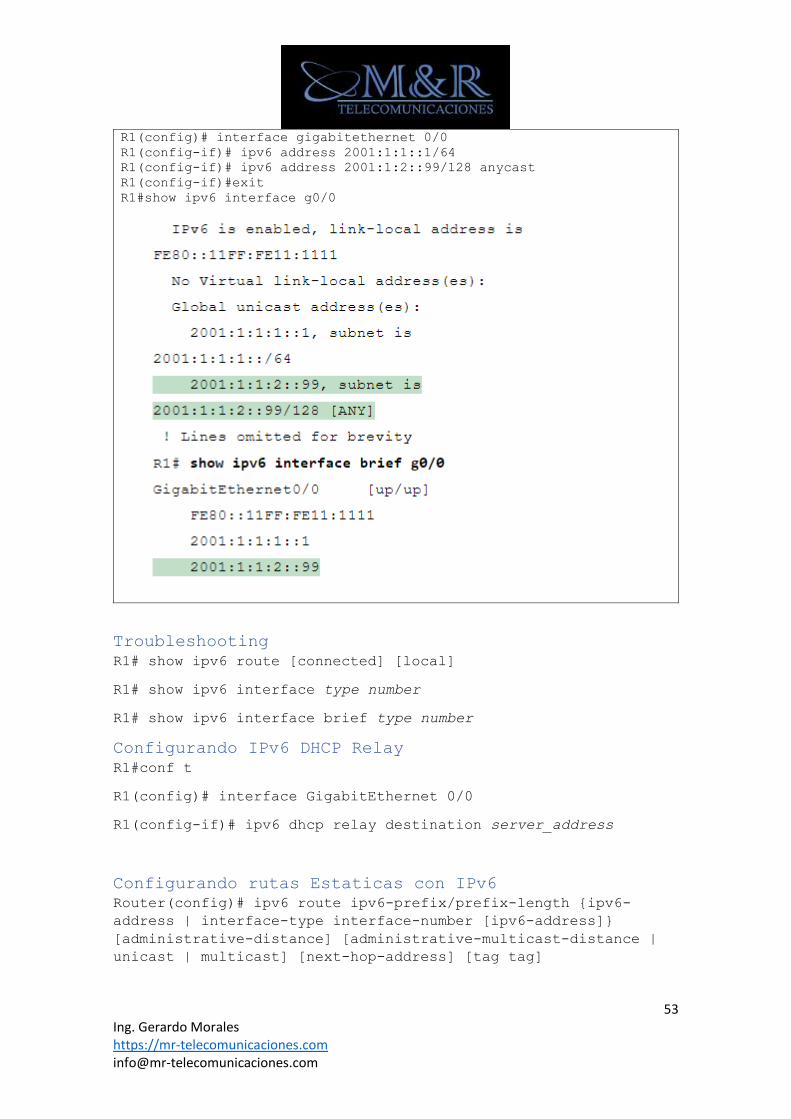
53 Ing. Gerardo Morales https://mr-telecomunicaciones.com [email protected]
R1(config)# interface gigabitethernet 0/0
R1(config-if)# ipv6 address 2001:1:1::1/64
R1(config-if)# ipv6 address 2001:1:2::99/128 anycast
R1(config-if)#exit
R1#show ipv6 interface g0/0
Troubleshooting
R1# show ipv6 route [connected] [local]
R1# show ipv6 interface type number
R1# show ipv6 interface brief type number
Configurando IPv6 DHCP Relay
R1#conf t
R1(config)# interface GigabitEthernet 0/0
R1(config-if)# ipv6 dhcp relay destination server_address
Configurando rutas Estaticas con IPv6
Router(config)# ipv6 route ipv6-prefix/prefix-length {ipv6-
address | interface-type interface-number [ipv6-address]}
[administrative-distance] [administrative-multicast-distance |
unicast | multicast] [next-hop-address] [tag tag]
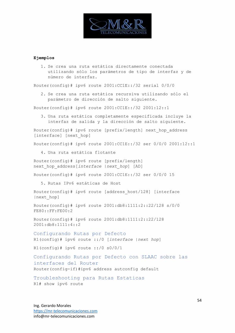
54 Ing. Gerardo Morales https://mr-telecomunicaciones.com [email protected]
Ejemplos
1. Se crea una ruta estática directamente conectada
utilizando sólo los parámetros de tipo de interfaz y de
número de interfaz.
Router(config)# ipv6 route 2001:CC1E::/32 serial 0/0/0
2. Se crea una ruta estática recursiva utilizando sólo el
parámetro de dirección de salto siguiente.
Router(config)# ipv6 route 2001:CC1E::/32 2001:12::1
3. Una ruta estática completamente especificada incluye la
interfaz de salida y la dirección de salto siguiente.
Router(config)# ipv6 route [prefix/length] next_hop_address
[interface] [next_hop]
Router(config)# ipv6 route 2001:CC1E::/32 ser 0/0/0 2001:12::1
4. Una ruta estática flotante
Router(config)# ipv6 route [prefix/length]
next_hop_address[interface |next_hop] [AD]
Router(config)# ipv6 route 2001:CC1E::/32 ser 0/0/0 15
5. Rutas IPv6 estáticas de Host
Router(config)# ipv6 route [address_host/128] [interface
|next_hop]
Router(config)# ipv6 route 2001:db8:1111:2::22/128 s/0/0
FE80::FF:FE00:2
Router(config)# ipv6 route 2001:db8:1111:2::22/128
2001:db8:1111:4::2
Configurando Rutas por Defecto
R1(config)# ipv6 route ::/0 [interface |next hop]
R1(config)# ipv6 route ::/0 s0/0/1
Configurando Rutas por Defecto con SLAAC sobre las
interfaces del Router
Router(config-if)#ipv6 address autconfig default
Troubleshooting para Rutas Estaticas
R1# show ipv6 route
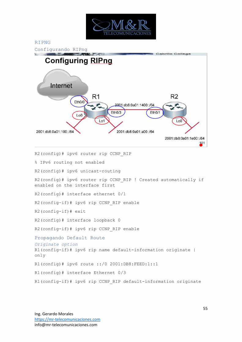
55 Ing. Gerardo Morales https://mr-telecomunicaciones.com [email protected]
RIPNG
Configurando RIPng
R2(config)# ipv6 router rip CCNP_RIP
% IPv6 routing not enabled
R2(config)# ipv6 unicast-routing
R2(config)# ipv6 router rip CCNP_RIP ! Created automatically if
enabled on the interface first
R2(config)# interface ethernet 0/1
R2(config-if)# ipv6 rip CCNP_RIP enable
R2(config-if)# exit
R2(config)# interface loopback 0
R2(config-if)# ipv6 rip CCNP_RIP enable
Propagando Default Route
Originate option
R1(config-if)# ipv6 rip name default-information originate |
only
R1(config)# ipv6 route ::/0 2001:DB8:FEED:1::1
R1(config)# interface Ethernet 0/3
R1(config-if)# ipv6 rip CCNP_RIP default-information originate
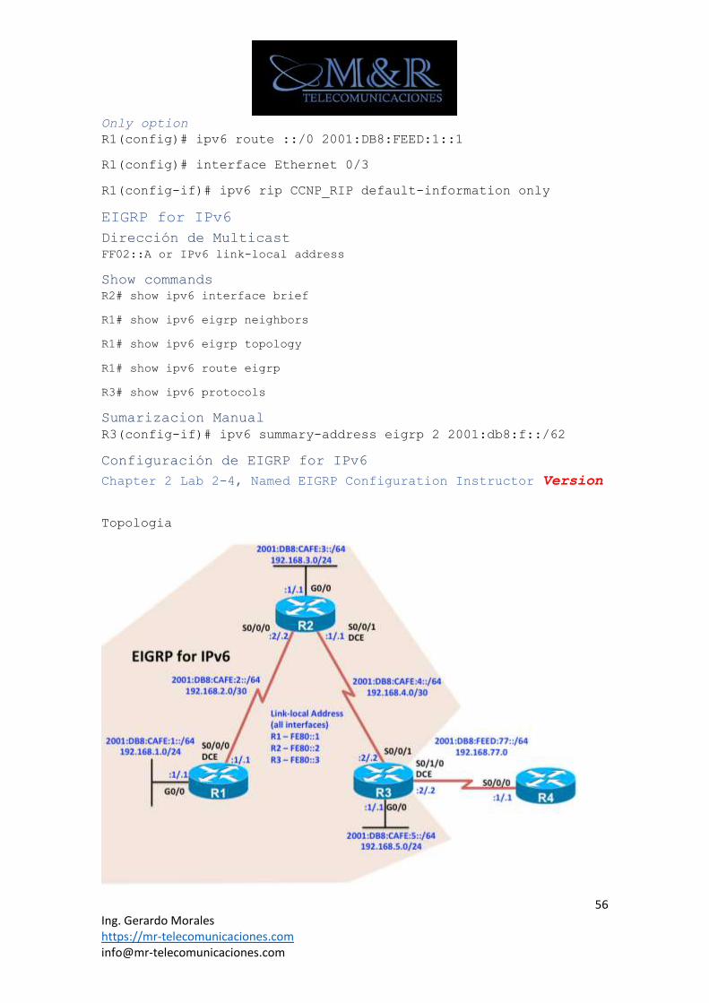
56 Ing. Gerardo Morales https://mr-telecomunicaciones.com [email protected]
Only option
R1(config)# ipv6 route ::/0 2001:DB8:FEED:1::1
R1(config)# interface Ethernet 0/3
R1(config-if)# ipv6 rip CCNP_RIP default-information only
EIGRP for IPv6
Dirección de Multicast
FF02::A or IPv6 link-local address
Show commands
R2# show ipv6 interface brief
R1# show ipv6 eigrp neighbors
R1# show ipv6 eigrp topology
R1# show ipv6 route eigrp
R3# show ipv6 protocols
Sumarizacion Manual
R3(config-if)# ipv6 summary-address eigrp 2 2001:db8:f::/62
Configuración de EIGRP for IPv6
Chapter 2 Lab 2-4, Named EIGRP Configuration Instructor Version
Topologia
57 Ing. Gerardo Morales https://mr-telecomunicaciones.com [email protected]
Objectives
• Configure Named EIGRP for IPv4 and IPv6.
• Verify Named EIGRP configuration.
• Configure and verify passive routes Named EIGRP
configuration.
• Configure and verify default route using Named EIGRP
configuration.
Background
What is known as “classic” EIGRP requires separate EIGRP
configuration modes and commands for IPv4 and IPv6. Each process is
configured separately, router eigrp as-number for IPv4 and ipv6
router eigrp as-number for IPv6.
Named EIGRP uses the address family (AF) feature to unify the
configuration process when implementing both IPv4 and IPv6. In this
lab, you will configure named EIGRP for IPv4 and IPv6.
Note: This lab uses Cisco 1941 routers with Cisco IOS Release 15.4
with IP Base. The switches are Cisco WS-C2960-24TT-L with
Fast Ethernet interfaces, therefore the router will use routing
metrics associated with a 100 Mb/s interface. Depending on the
router or switch model and Cisco IOS Software version, the commands
available and output produced might vary from what is shown in this
lab.
Required Resources
• 4 routers (Cisco IOS Release 15.2 or comparable)
• 3 switches (LAN interfaces)
• Serial and Ethernet cables
Step 0: Suggested starting configurations.
a. Apply the following configuration to each router along with the
appropriate hostname. The exec-timeout 0 0 command should only
be used in a lab environment.
Router(config)# no ip domain-lookup
Router(config)# line con 0
Router(config-line)# logging synchronous
Router(config-line)# exec-timeout 0 0
Step 1: Configure the addressing and serial links.
a. Using the topology, configure the IPv4 and IPv6 addresses on the
interfaces of each router.
R1(config)# interface GigabitEthernet0/0
R1(config-if)# ip address 192.168.1.1 255.255.255.0
58 Ing. Gerardo Morales https://mr-telecomunicaciones.com [email protected]
R1(config-if)# ipv6 address FE80::1 link-local
R1(config-if)# ipv6 address 2001:DB8:CAFE:1::1/64
R1(config-if)# no shutdown
R1(config-if)# exit
R1(config)# interface Serial0/0/0
R1(config-if)# ip address 192.168.2.1 255.255.255.252
R1(config-if)# ipv6 address FE80::1 link-local
R1(config-if)# ipv6 address 2001:DB8:CAFE:2::1/64
R1(config-if)# clock rate 64000
R1(config-if)# no shutdown
R2(config)# interface GigabitEthernet0/0
R2(config-if)# ip address 192.168.3.1 255.255.255.0
R2(config-if)# ipv6 address FE80::2 link-local
R2(config-if)# ipv6 address 2001:DB8:CAFE:3::1/64
R2(config-if)# no shutdown
R2(config-if)# exit
R2(config)# interface Serial0/0/0
R2(config-if)# ip address 192.168.2.2 255.255.255.252
R2(config-if)# ipv6 address FE80::2 link-local
R2(config-if)# ipv6 address 2001:DB8:CAFE:2::2/64
R2(config-if)# no shutdown
R2(config-if)# exit
R2(config)# interface Serial0/0/1
R2(config-if)# ip address 192.168.4.1 255.255.255.252
R2(config-if)# ipv6 address FE80::2 link-local
R2(config-if)# ipv6 address 2001:DB8:CAFE:4::1/64
R2(config-if)# clock rate 64000
R2(config-if)# no shutdown
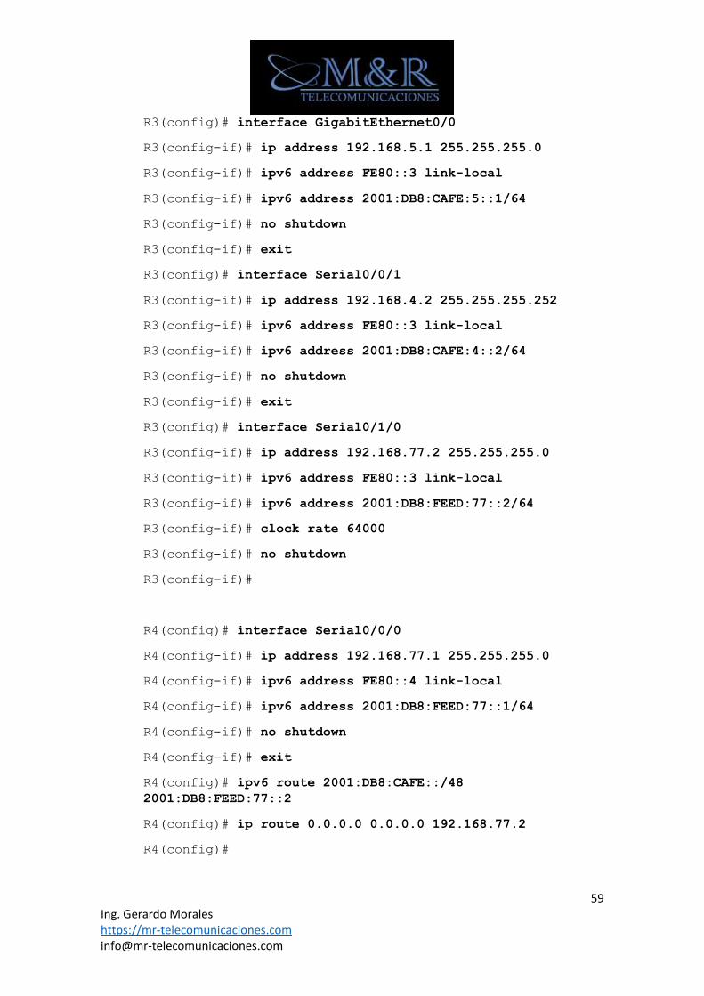
59 Ing. Gerardo Morales https://mr-telecomunicaciones.com [email protected]
R3(config)# interface GigabitEthernet0/0
R3(config-if)# ip address 192.168.5.1 255.255.255.0
R3(config-if)# ipv6 address FE80::3 link-local
R3(config-if)# ipv6 address 2001:DB8:CAFE:5::1/64
R3(config-if)# no shutdown
R3(config-if)# exit
R3(config)# interface Serial0/0/1
R3(config-if)# ip address 192.168.4.2 255.255.255.252
R3(config-if)# ipv6 address FE80::3 link-local
R3(config-if)# ipv6 address 2001:DB8:CAFE:4::2/64
R3(config-if)# no shutdown
R3(config-if)# exit
R3(config)# interface Serial0/1/0
R3(config-if)# ip address 192.168.77.2 255.255.255.0
R3(config-if)# ipv6 address FE80::3 link-local
R3(config-if)# ipv6 address 2001:DB8:FEED:77::2/64
R3(config-if)# clock rate 64000
R3(config-if)# no shutdown
R3(config-if)#
R4(config)# interface Serial0/0/0
R4(config-if)# ip address 192.168.77.1 255.255.255.0
R4(config-if)# ipv6 address FE80::4 link-local
R4(config-if)# ipv6 address 2001:DB8:FEED:77::1/64
R4(config-if)# no shutdown
R4(config-if)# exit
R4(config)# ipv6 route 2001:DB8:CAFE::/48
2001:DB8:FEED:77::2
R4(config)# ip route 0.0.0.0 0.0.0.0 192.168.77.2
R4(config)#
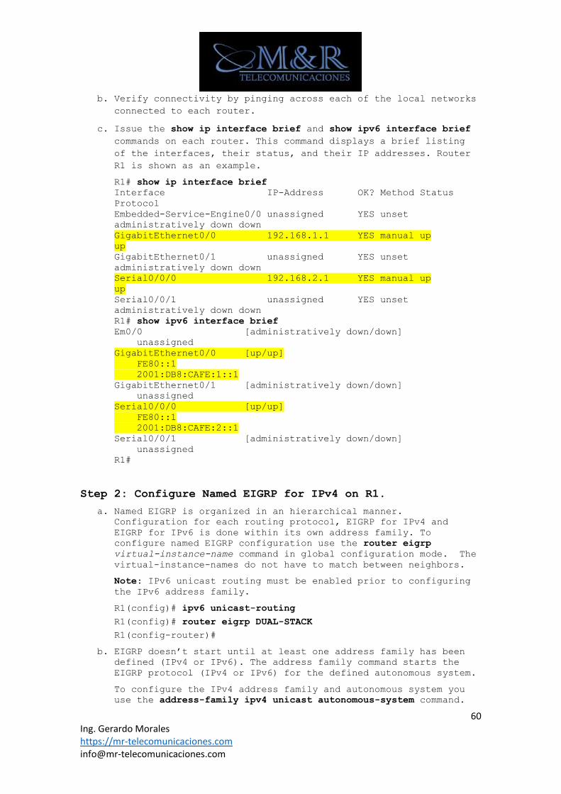
60 Ing. Gerardo Morales https://mr-telecomunicaciones.com [email protected]
b. Verify connectivity by pinging across each of the local networks
connected to each router.
c. Issue the show ip interface brief and show ipv6 interface brief
commands on each router. This command displays a brief listing
of the interfaces, their status, and their IP addresses. Router
R1 is shown as an example.
R1# show ip interface brief
Interface IP-Address OK? Method Status
Protocol
Embedded-Service-Engine0/0 unassigned YES unset
administratively down down
GigabitEthernet0/0 192.168.1.1 YES manual up
up
GigabitEthernet0/1 unassigned YES unset
administratively down down
Serial0/0/0 192.168.2.1 YES manual up
up
Serial0/0/1 unassigned YES unset
administratively down down
R1# show ipv6 interface brief
Em0/0 [administratively down/down]
unassigned
GigabitEthernet0/0 [up/up]
FE80::1
2001:DB8:CAFE:1::1
GigabitEthernet0/1 [administratively down/down]
unassigned
Serial0/0/0 [up/up]
FE80::1
2001:DB8:CAFE:2::1
Serial0/0/1 [administratively down/down]
unassigned
R1#
Step 2: Configure Named EIGRP for IPv4 on R1.
a. Named EIGRP is organized in an hierarchical manner. Configuration for each routing protocol, EIGRP for IPv4 and
EIGRP for IPv6 is done within its own address family. To
configure named EIGRP configuration use the router eigrp
virtual-instance-name command in global configuration mode. The
virtual-instance-names do not have to match between neighbors.
Note: IPv6 unicast routing must be enabled prior to configuring
the IPv6 address family.
R1(config)# ipv6 unicast-routing
R1(config)# router eigrp DUAL-STACK
R1(config-router)#
b. EIGRP doesn’t start until at least one address family has been defined (IPv4 or IPv6). The address family command starts the
EIGRP protocol (IPv4 or IPv6) for the defined autonomous system.
To configure the IPv4 address family and autonomous system you
use the address-family ipv4 unicast autonomous-system command.
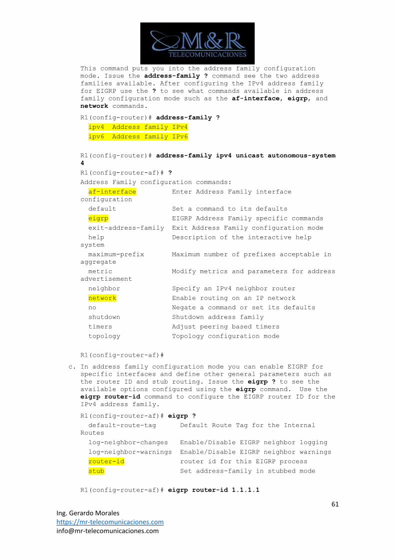
61 Ing. Gerardo Morales https://mr-telecomunicaciones.com [email protected]
This command puts you into the address family configuration
mode. Issue the address-family ? command see the two address
families available. After configuring the IPv4 address family
for EIGRP use the ? to see what commands available in address
family configuration mode such as the af-interface, eigrp, and
network commands.
R1(config-router)# address-family ?
ipv4 Address family IPv4
ipv6 Address family IPv6
R1(config-router)# address-family ipv4 unicast autonomous-system
4
R1(config-router-af)# ?
Address Family configuration commands:
af-interface Enter Address Family interface
configuration
default Set a command to its defaults
eigrp EIGRP Address Family specific commands
exit-address-family Exit Address Family configuration mode
help Description of the interactive help
system
maximum-prefix Maximum number of prefixes acceptable in
aggregate
metric Modify metrics and parameters for address
advertisement
neighbor Specify an IPv4 neighbor router
network Enable routing on an IP network
no Negate a command or set its defaults
shutdown Shutdown address family
timers Adjust peering based timers
topology Topology configuration mode
R1(config-router-af)#
c. In address family configuration mode you can enable EIGRP for specific interfaces and define other general parameters such as
the router ID and stub routing. Issue the eigrp ? to see the
available options configured using the eigrp command. Use the
eigrp router-id command to configure the EIGRP router ID for the
IPv4 address family.
R1(config-router-af)# eigrp ?
default-route-tag Default Route Tag for the Internal
Routes
log-neighbor-changes Enable/Disable EIGRP neighbor logging
log-neighbor-warnings Enable/Disable EIGRP neighbor warnings
router-id router id for this EIGRP process
stub Set address-family in stubbed mode
R1(config-router-af)# eigrp router-id 1.1.1.1
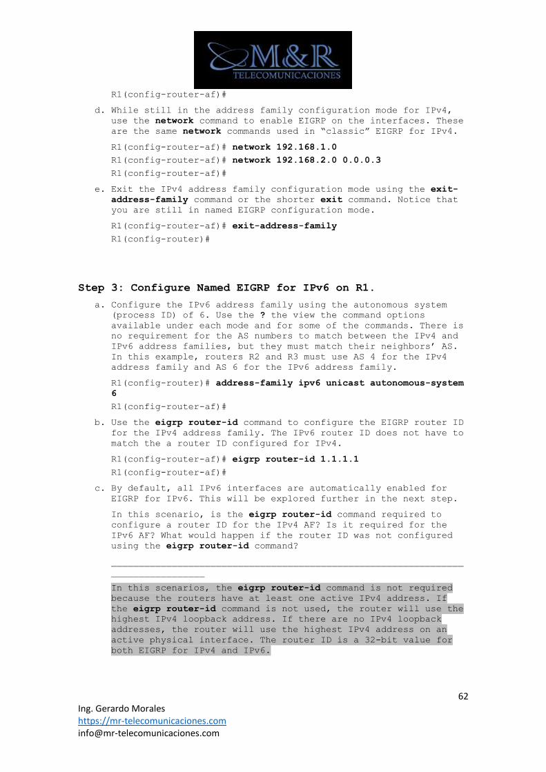
62 Ing. Gerardo Morales https://mr-telecomunicaciones.com [email protected]
R1(config-router-af)#
d. While still in the address family configuration mode for IPv4, use the network command to enable EIGRP on the interfaces. These
are the same network commands used in “classic” EIGRP for IPv4.
R1(config-router-af)# network 192.168.1.0
R1(config-router-af)# network 192.168.2.0 0.0.0.3
R1(config-router-af)#
e. Exit the IPv4 address family configuration mode using the exit-address-family command or the shorter exit command. Notice that
you are still in named EIGRP configuration mode.
R1(config-router-af)# exit-address-family
R1(config-router)#
Step 3: Configure Named EIGRP for IPv6 on R1.
a. Configure the IPv6 address family using the autonomous system (process ID) of 6. Use the ? the view the command options
available under each mode and for some of the commands. There is
no requirement for the AS numbers to match between the IPv4 and
IPv6 address families, but they must match their neighbors’ AS.
In this example, routers R2 and R3 must use AS 4 for the IPv4
address family and AS 6 for the IPv6 address family.
R1(config-router)# address-family ipv6 unicast autonomous-system
6
R1(config-router-af)#
b. Use the eigrp router-id command to configure the EIGRP router ID for the IPv4 address family. The IPv6 router ID does not have to
match the a router ID configured for IPv4.
R1(config-router-af)# eigrp router-id 1.1.1.1
R1(config-router-af)#
c. By default, all IPv6 interfaces are automatically enabled for EIGRP for IPv6. This will be explored further in the next step.
In this scenario, is the eigrp router-id command required to
configure a router ID for the IPv4 AF? Is it required for the
IPv6 AF? What would happen if the router ID was not configured
using the eigrp router-id command?
________________________________________________________________
_________________
In this scenarios, the eigrp router-id command is not required
because the routers have at least one active IPv4 address. If
the eigrp router-id command is not used, the router will use the
highest IPv4 loopback address. If there are no IPv4 loopback
addresses, the router will use the highest IPv4 address on an
active physical interface. The router ID is a 32-bit value for
both EIGRP for IPv4 and IPv6.
63 Ing. Gerardo Morales https://mr-telecomunicaciones.com [email protected]
Step 4: Configure Named EIGRP on R2 and R3.
a. Configure named EIGRP on R2 for the IPv4 address family. The IPv6 unicast routing is enabled in preparation for configuring
the IPv6 address family.
R2(config)# ipv6 unicast-routing
R2(config)# router eigrp DUAL-STACK
R2(config-router)# address-family ipv4 unicast autonomous-system
4
R2(config-router-af)# eigrp router-id 2.2.2.2
R2(config-router-af)# network 192.168.2.0 0.0.0.3
*Jul 25 20:11:37.643: %DUAL-5-NBRCHANGE: EIGRP-IPv4 4: Neighbor
192.168.2.1 (Serial0/0/0) is up: new adjacency
R2(config-router-af)# network 192.168.3.0
R2(config-router-af)# network 192.168.4.0 0.0.0.3
R2(config-router-af)# exit-address-family
R2(config-router)#
Notice that the adjacency between R1 and R2 is established after
enabling EIGRP for IPv4 on the serial 0/0/0 interface.
b. Configure the IPv6 address family for EIGRP on R2.
R2(config-router)# address-family ipv6 unicast autonomous-system
6
*Jul 25 20:19:05.435: %DUAL-5-NBRCHANGE: EIGRP-IPv6 6: Neighbor
FE80::1 (Serial0/0/0) is up: new adjacency
R2(config-router-af)# eigrp router-id 2.2.2.2
R2(config-router-af)#
Notice that the IPv6 adjacency with R1 comes up immediately
after configuring the IPv6 AF. This is because by default, all
IPv6 interfaces are enabled automatically.
c. On R3, configure named EIGRP on R3 for both the IPv4 and IPv6 address families. After the appropriate commands are configured
the IPv4 and IPv6 EIGRP adjacencies are established between R2
and R3. The serial link between R3 and R4 is also automatically
enabled in EIGRP for IPv6. This link is not suppose to be
included and will be disabled in EIGRP for IPv6 later in step 6.
R3(config)# ipv6 unicast-routing
R3(config)# router eigrp DUAL-STACK
R3(config-router)# address-family ipv4 unicast autonomous-system
4
R3(config-router-af)# eigrp router-id 3.3.3.3
R3(config-router-af)# network 192.168.4.0 0.0.0.3
*Jun 26 13:11:41.343: %DUAL-5-NBRCHANGE: EIGRP-IPv4 4: Neighbor
192.168.4.1 (Serial0/0/1) is up: new adjacency
R3(config-router-af)# network 192.168.5.0
R3(config-router-af)# exit-address-family
R3(config-router)# address-family ipv6 unicast autonomous-system
6
64 Ing. Gerardo Morales https://mr-telecomunicaciones.com [email protected]
*Jun 26 13:12:22.819: %DUAL-5-NBRCHANGE: EIGRP-IPv6 6: Neighbor
FE80::2 (Serial0/0/1) is up: new adjacency
R3(config-router-af)# eigrp router-id 3.3.3.3
R3(config-router-af)#
Step 5: Configure passive interfaces for named EIGRP.
a. Within each IPv4 and IPv6 AF is the address family interface configuration mode. This mode is used to configure EIGRP
specific parameters on an interface, such as the hello timer and
summarization. From address family configuration mode, use the
af-interface interface-type interface-number command to enter
address family interface configuration mode. The following
output shows the sequence of commands starting from global
configuration mode.
R1(config)# router eigrp DUAL-STACK
R1(config-router)# address-family ipv4 unicast autonomous-system
4
R1(config-router-af)# af-interface gigabitethernet 0/0
R1(config-router-af-interface)#
b. Issue the ? to see the commands available in address family interface configuration mode. Notice various commands to
configure interface specific parameters such as the hello
interval, hold timer, passive interfaces, and summarization.
R1(config-router-af-interface)# ?
Address Family Interfaces configuration commands:
add-paths Advertise add paths
authentication authentication subcommands
bandwidth-percent Set percentage of bandwidth percentage
limit
bfd Enable Bidirectional Forwarding Detection
dampening-change Percent interface metric must change to
cause update
dampening-interval Time in seconds to check interface metrics
default Set a command to its defaults
exit-af-interface Exit from Address Family Interface
configuration mode
hello-interval Configures hello interval
hold-time Configures hold time
next-hop-self Configures EIGRP next-hop-self
no Negate a command or set its defaults
passive-interface Suppress address updates on an interface
shutdown Disable Address-Family on interface
split-horizon Perform split horizon
summary-address Perform address summarization
R1(config-router-af-interface)#
65 Ing. Gerardo Morales https://mr-telecomunicaciones.com [email protected]
The interface configuration mode commands are similar for both
the IPv4 and IPv6 address families. Commands issued are specific
for an interface within the address family, IPv4 or IPv6.
c. Using the passive-interface command, configure G0/0 interface as passive for both the IPv4 and IPv6 EIGRP address families.
R1(config-router-af-interface)# passive-interface
R1(config-router-af-interface)# exit-af-interface
R1(config-router-af)# exit-address-family
R1(config-router)# address-family ipv6 unicast autonomous-system
6
R1(config-router-af)# af-interface gigabitethernet 0/0
R1(config-router-af-interface)# passive-interface
R1(config-router-af-interface)# exit-af-interface
R1(config-router-af)# exit-address-family
R1(config-router)#
d. Configure R2’s G0/0 interface as passive for both the IPv4 and IPv6 address families.
R2(config)# router eigrp DUAL-STACK
R2(config-router)# address-family ipv4 unicast autonomous-system
4
R2(config-router-af)# af-interface gigabitethernet 0/0
R2(config-router-af-interface)# passive-interface
R2(config-router-af-interface)# exit-af-interface
R2(config-router-af)# exit-address-family
R2(config-router)# address-family ipv6 unicast autonomous-system
6
R2(config-router-af)# af-interface gigabitethernet 0/0
R2(config-router-af-interface)# passive-interface
R2(config-router-af-interface)# exit
R2(config-router-af)# exit
R2(config-router)#
e. Configure R3’s G0/0 interface as passive for both the IPv4 and IPv6 address families.
R3(config)# router eigrp DUAL-STACK
R3(config-router)# address-family ipv4 unicast autonomous-system
4
R3(config-router-af)# af-interface gigabitethernet 0/0
R3(config-router-af-interface)# passive-interface
R3(config-router-af-interface)# exit-af-interface
R3(config-router-af)# exit-address-family
R3(config-router)# address-family ipv6 unicast autonomous-system
6
R3(config-router-af)# af-interface gigabitethernet 0/0
R3(config-router-af-interface)# passive-interface
R3(config-router-af-interface)# exit
66 Ing. Gerardo Morales https://mr-telecomunicaciones.com [email protected]
R3(config-router-af)# exit
R3(config-router)#
Notice the exit command was used as the shorter method for the
exit-af-interface and exit-address-family commands.
Step 6: Disable named EIGRP on a specific IPv6 interface.
a. By default, all IPv6 interfaces are enabled for EIGRP for IPv6. This happens when enabling the IPv6 address family with the
address-family ipv6 unicast autonomous-system command. Issue the
show ipv6 protocols command on R3 to verify that all three of
its IPv6 interfaces are enabled for EIGRP for IPv6. Notice that
the Serial 0/1/0 interface is also included.
R3# show ipv6 protocols
IPv6 Routing Protocol is "connected"
IPv6 Routing Protocol is "application"
IPv6 Routing Protocol is "ND"
IPv6 Routing Protocol is "eigrp 6"
EIGRP-IPv6 VR(DUAL-STACK) Address-Family Protocol for AS(6)
Metric weight K1=1, K2=0, K3=1, K4=0, K5=0 K6=0
Metric rib-scale 128
Metric version 64bit
NSF-aware route hold timer is 240
Router-ID: 3.3.3.3
Topology : 0 (base)
Active Timer: 3 min
Distance: internal 90 external 170
Maximum path: 16
Maximum hopcount 100
Maximum metric variance 1
Total Prefix Count: 6
Total Redist Count: 0
Interfaces:
Serial0/0/1
Serial0/1/0
GigabitEthernet0/0 (passive)
Redistribution:
None
R3#
b. As shown in the topology, R3’s S0/1/0 interface does not need to be included in the EIGRP updates. A default route will be
configured later in this lab for reachability beyond the EIGRP
routing domain. When we configured the IPv4 AF we excluded the
network command for this interface. However, the same interface
is automatically included when configuring the IPv6 AF. The
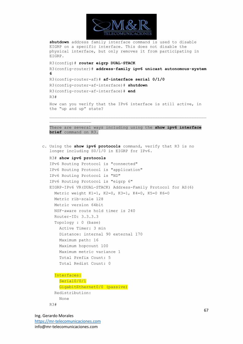
67 Ing. Gerardo Morales https://mr-telecomunicaciones.com [email protected]
shutdown address family interface command is used to disable
EIGRP on a specific interface. This does not disable the
physical interface, but only removes it from participating in
EIGRP.
R3(config)# router eigrp DUAL-STACK
R3(config-router)# address-family ipv6 unicast autonomous-system
6
R3(config-router-af)# af-interface serial 0/1/0
R3(config-router-af-interface)# shutdown
R3(config-router-af-interface)# end
R3#
How can you verify that the IPv6 interface is still active, in
the “up and up” state?
________________________________________________________________
_________________
There are several ways including using the show ipv6 interface
brief command on R3.
c. Using the show ipv6 protocols command, verify that R3 is no longer including S0/1/0 in EIGRP for IPv6.
R3# show ipv6 protocols
IPv6 Routing Protocol is "connected"
IPv6 Routing Protocol is "application"
IPv6 Routing Protocol is "ND"
IPv6 Routing Protocol is "eigrp 6"
EIGRP-IPv6 VR(DUAL-STACK) Address-Family Protocol for AS(6)
Metric weight K1=1, K2=0, K3=1, K4=0, K5=0 K6=0
Metric rib-scale 128
Metric version 64bit
NSF-aware route hold timer is 240
Router-ID: 3.3.3.3
Topology : 0 (base)
Active Timer: 3 min
Distance: internal 90 external 170
Maximum path: 16
Maximum hopcount 100
Maximum metric variance 1
Total Prefix Count: 5
Total Redist Count: 0
Interfaces:
Serial0/0/1
GigabitEthernet0/0 (passive)
Redistribution:
None
R3#
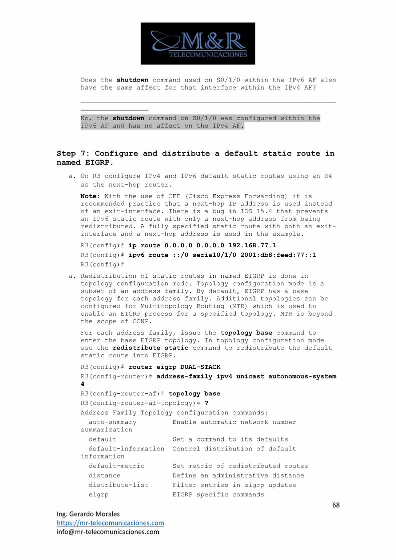
68 Ing. Gerardo Morales https://mr-telecomunicaciones.com [email protected]
Does the shutdown command used on S0/1/0 within the IPv6 AF also
have the same affect for that interface within the IPv4 AF?
________________________________________________________________
_________________
No, the shutdown command on S0/1/0 was configured within the
IPv6 AF and has no affect on the IPv4 AF.
Step 7: Configure and distribute a default static route in
named EIGRP.
a. On R3 configure IPv4 and IPv6 default static routes using an R4
as the next-hop router.
Note: With the use of CEF (Cisco Express Forwarding) it is
recommended practice that a next-hop IP address is used instead
of an exit-interface. There is a bug in IOS 15.4 that prevents
an IPv6 static route with only a next-hop address from being
redistributed. A fully specified static route with both an exit-
interface and a next-hop address is used in the example.
R3(config)# ip route 0.0.0.0 0.0.0.0 192.168.77.1
R3(config)# ipv6 route ::/0 serial0/1/0 2001:db8:feed:77::1
R3(config)#
a. Redistribution of static routes in named EIGRP is done in topology configuration mode. Topology configuration mode is a
subset of an address family. By default, EIGRP has a base
topology for each address family. Additional topologies can be
configured for Multitopology Routing (MTR) which is used to
enable an EIGRP process for a specified topology. MTR is beyond
the scope of CCNP.
For each address family, issue the topology base command to
enter the base EIGRP topology. In topology configuration mode
use the redistribute static command to redistribute the default
static route into EIGRP.
R3(config)# router eigrp DUAL-STACK
R3(config-router)# address-family ipv4 unicast autonomous-system
4
R3(config-router-af)# topology base
R3(config-router-af-topology)# ?
Address Family Topology configuration commands:
auto-summary Enable automatic network number
summarization
default Set a command to its defaults
default-information Control distribution of default
information
default-metric Set metric of redistributed routes
distance Define an administrative distance
distribute-list Filter entries in eigrp updates
eigrp EIGRP specific commands
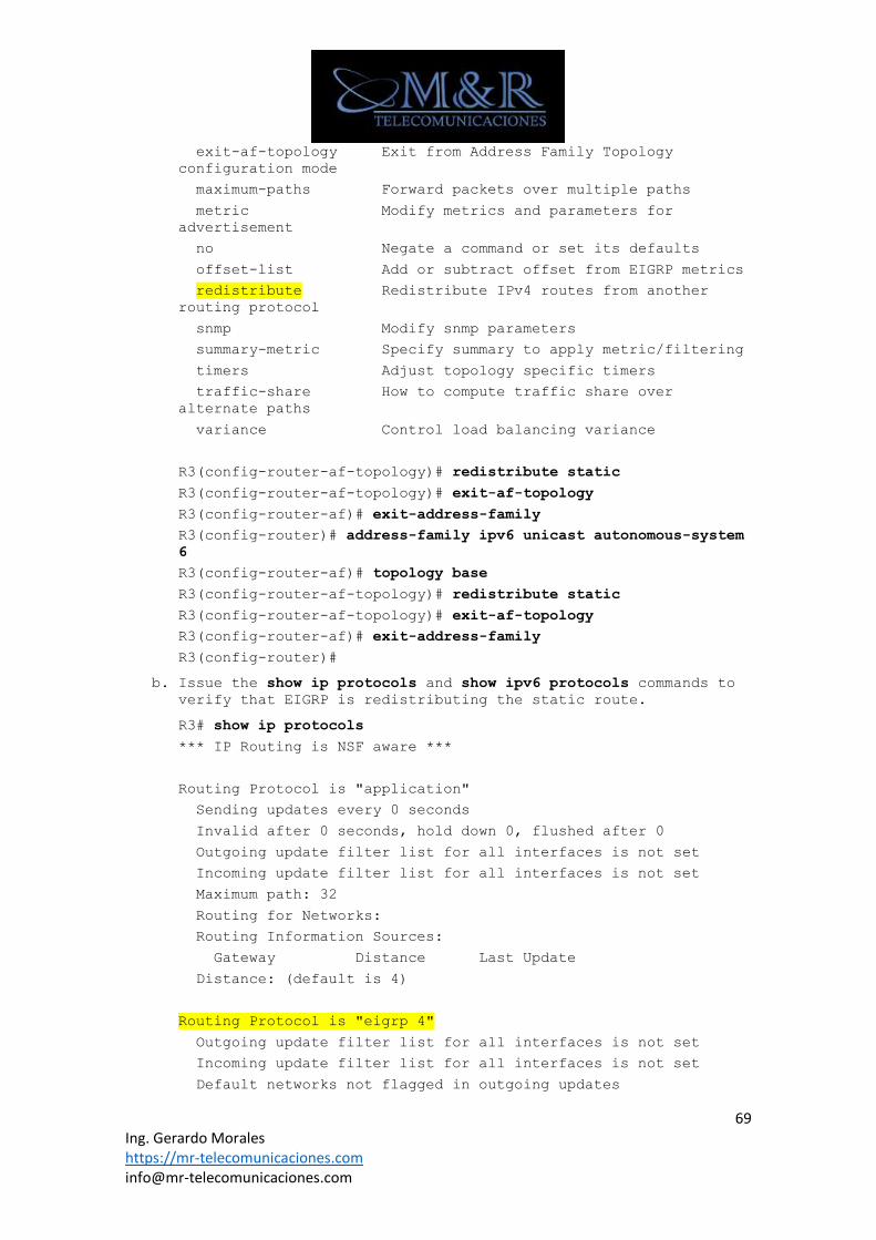
69 Ing. Gerardo Morales https://mr-telecomunicaciones.com [email protected]
exit-af-topology Exit from Address Family Topology
configuration mode
maximum-paths Forward packets over multiple paths
metric Modify metrics and parameters for
advertisement
no Negate a command or set its defaults
offset-list Add or subtract offset from EIGRP metrics
redistribute Redistribute IPv4 routes from another
routing protocol
snmp Modify snmp parameters
summary-metric Specify summary to apply metric/filtering
timers Adjust topology specific timers
traffic-share How to compute traffic share over
alternate paths
variance Control load balancing variance
R3(config-router-af-topology)# redistribute static
R3(config-router-af-topology)# exit-af-topology
R3(config-router-af)# exit-address-family
R3(config-router)# address-family ipv6 unicast autonomous-system
6
R3(config-router-af)# topology base
R3(config-router-af-topology)# redistribute static
R3(config-router-af-topology)# exit-af-topology
R3(config-router-af)# exit-address-family
R3(config-router)#
b. Issue the show ip protocols and show ipv6 protocols commands to verify that EIGRP is redistributing the static route.
R3# show ip protocols
*** IP Routing is NSF aware ***
Routing Protocol is "application"
Sending updates every 0 seconds
Invalid after 0 seconds, hold down 0, flushed after 0
Outgoing update filter list for all interfaces is not set
Incoming update filter list for all interfaces is not set
Maximum path: 32
Routing for Networks:
Routing Information Sources:
Gateway Distance Last Update
Distance: (default is 4)
Routing Protocol is "eigrp 4"
Outgoing update filter list for all interfaces is not set
Incoming update filter list for all interfaces is not set
Default networks not flagged in outgoing updates
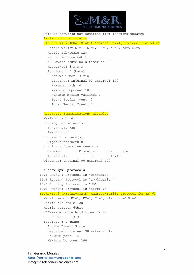
70 Ing. Gerardo Morales https://mr-telecomunicaciones.com [email protected]
Default networks not accepted from incoming updates
Redistributing: static
EIGRP-IPv4 VR(DUAL-STACK) Address-Family Protocol for AS(4)
Metric weight K1=1, K2=0, K3=1, K4=0, K5=0 K6=0
Metric rib-scale 128
Metric version 64bit
NSF-aware route hold timer is 240
Router-ID: 3.3.3.3
Topology : 0 (base)
Active Timer: 3 min
Distance: internal 90 external 170
Maximum path: 4
Maximum hopcount 100
Maximum metric variance 1
Total Prefix Count: 5
Total Redist Count: 1
Automatic Summarization: disabled
Maximum path: 4
Routing for Networks:
192.168.4.0/30
192.168.5.0
Passive Interface(s):
GigabitEthernet0/0
Routing Information Sources:
Gateway Distance Last Update
192.168.4.1 90 02:07:02
Distance: internal 90 external 170
R3# show ipv6 protocols
IPv6 Routing Protocol is "connected"
IPv6 Routing Protocol is "application"
IPv6 Routing Protocol is "ND"
IPv6 Routing Protocol is "eigrp 6"
EIGRP-IPv6 VR(DUAL-STACK) Address-Family Protocol for AS(6)
Metric weight K1=1, K2=0, K3=1, K4=0, K5=0 K6=0
Metric rib-scale 128
Metric version 64bit
NSF-aware route hold timer is 240
Router-ID: 3.3.3.3
Topology : 0 (base)
Active Timer: 3 min
Distance: internal 90 external 170
Maximum path: 16
Maximum hopcount 100
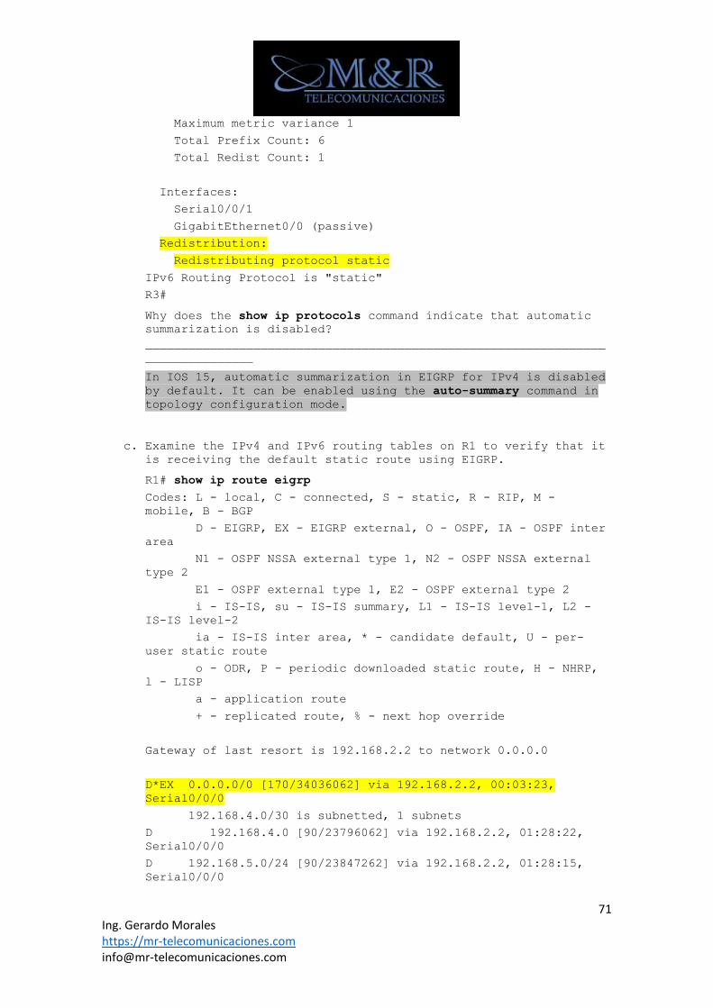
71 Ing. Gerardo Morales https://mr-telecomunicaciones.com [email protected]
Maximum metric variance 1
Total Prefix Count: 6
Total Redist Count: 1
Interfaces:
Serial0/0/1
GigabitEthernet0/0 (passive)
Redistribution:
Redistributing protocol static
IPv6 Routing Protocol is "static"
R3#
Why does the show ip protocols command indicate that automatic
summarization is disabled?
________________________________________________________________
_______________
In IOS 15, automatic summarization in EIGRP for IPv4 is disabled
by default. It can be enabled using the auto-summary command in
topology configuration mode.
c. Examine the IPv4 and IPv6 routing tables on R1 to verify that it is receiving the default static route using EIGRP.
R1# show ip route eigrp
Codes: L - local, C - connected, S - static, R - RIP, M -
mobile, B - BGP
D - EIGRP, EX - EIGRP external, O - OSPF, IA - OSPF inter
area
N1 - OSPF NSSA external type 1, N2 - OSPF NSSA external
type 2
E1 - OSPF external type 1, E2 - OSPF external type 2
i - IS-IS, su - IS-IS summary, L1 - IS-IS level-1, L2 -
IS-IS level-2
ia - IS-IS inter area, * - candidate default, U - per-
user static route
o - ODR, P - periodic downloaded static route, H - NHRP,
l - LISP
a - application route
+ - replicated route, % - next hop override
Gateway of last resort is 192.168.2.2 to network 0.0.0.0
D*EX 0.0.0.0/0 [170/34036062] via 192.168.2.2, 00:03:23,
Serial0/0/0
192.168.4.0/30 is subnetted, 1 subnets
D 192.168.4.0 [90/23796062] via 192.168.2.2, 01:28:22,
Serial0/0/0
D 192.168.5.0/24 [90/23847262] via 192.168.2.2, 01:28:15,
Serial0/0/0
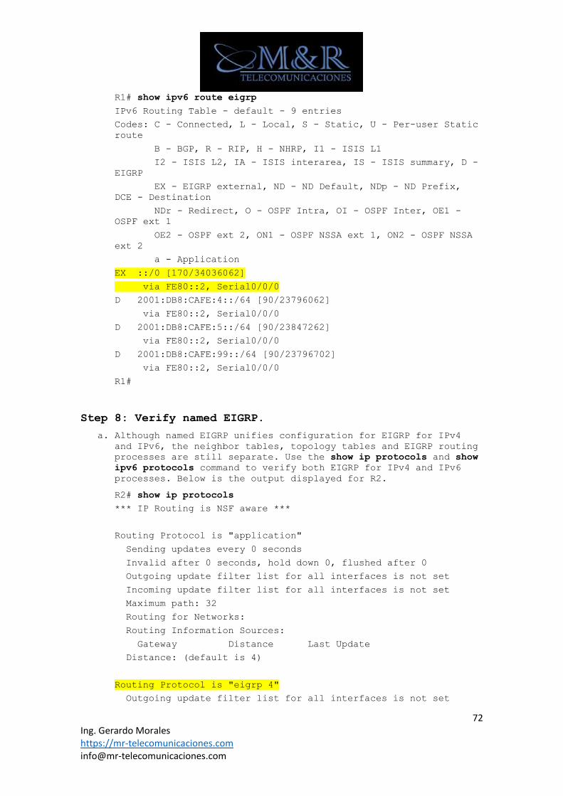
72 Ing. Gerardo Morales https://mr-telecomunicaciones.com [email protected]
R1# show ipv6 route eigrp
IPv6 Routing Table - default - 9 entries
Codes: C - Connected, L - Local, S - Static, U - Per-user Static
route
B - BGP, R - RIP, H - NHRP, I1 - ISIS L1
I2 - ISIS L2, IA - ISIS interarea, IS - ISIS summary, D -
EIGRP
EX - EIGRP external, ND - ND Default, NDp - ND Prefix,
DCE - Destination
NDr - Redirect, O - OSPF Intra, OI - OSPF Inter, OE1 -
OSPF ext 1
OE2 - OSPF ext 2, ON1 - OSPF NSSA ext 1, ON2 - OSPF NSSA
ext 2
a - Application
EX ::/0 [170/34036062]
via FE80::2, Serial0/0/0
D 2001:DB8:CAFE:4::/64 [90/23796062]
via FE80::2, Serial0/0/0
D 2001:DB8:CAFE:5::/64 [90/23847262]
via FE80::2, Serial0/0/0
D 2001:DB8:CAFE:99::/64 [90/23796702]
via FE80::2, Serial0/0/0
R1#
Step 8: Verify named EIGRP.
a. Although named EIGRP unifies configuration for EIGRP for IPv4 and IPv6, the neighbor tables, topology tables and EIGRP routing
processes are still separate. Use the show ip protocols and show
ipv6 protocols command to verify both EIGRP for IPv4 and IPv6
processes. Below is the output displayed for R2.
R2# show ip protocols
*** IP Routing is NSF aware ***
Routing Protocol is "application"
Sending updates every 0 seconds
Invalid after 0 seconds, hold down 0, flushed after 0
Outgoing update filter list for all interfaces is not set
Incoming update filter list for all interfaces is not set
Maximum path: 32
Routing for Networks:
Routing Information Sources:
Gateway Distance Last Update
Distance: (default is 4)
Routing Protocol is "eigrp 4"
Outgoing update filter list for all interfaces is not set
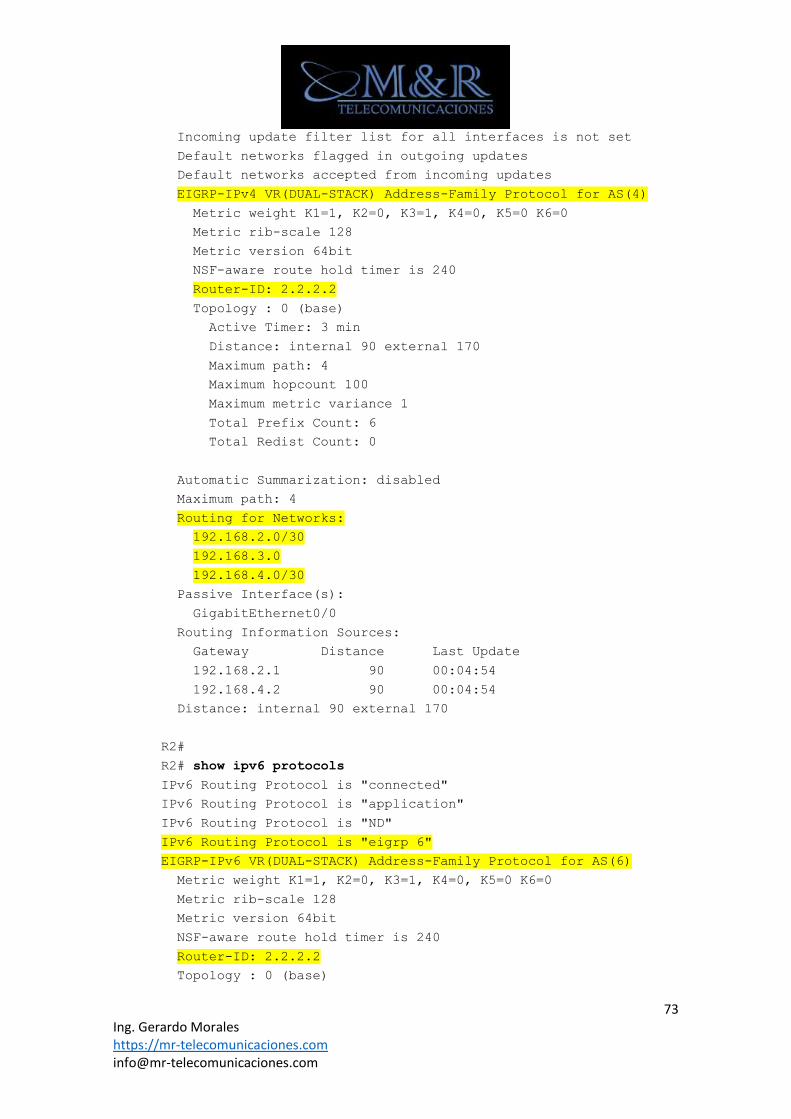
73 Ing. Gerardo Morales https://mr-telecomunicaciones.com [email protected]
Incoming update filter list for all interfaces is not set
Default networks flagged in outgoing updates
Default networks accepted from incoming updates
EIGRP-IPv4 VR(DUAL-STACK) Address-Family Protocol for AS(4)
Metric weight K1=1, K2=0, K3=1, K4=0, K5=0 K6=0
Metric rib-scale 128
Metric version 64bit
NSF-aware route hold timer is 240
Router-ID: 2.2.2.2
Topology : 0 (base)
Active Timer: 3 min
Distance: internal 90 external 170
Maximum path: 4
Maximum hopcount 100
Maximum metric variance 1
Total Prefix Count: 6
Total Redist Count: 0
Automatic Summarization: disabled
Maximum path: 4
Routing for Networks:
192.168.2.0/30
192.168.3.0
192.168.4.0/30
Passive Interface(s):
GigabitEthernet0/0
Routing Information Sources:
Gateway Distance Last Update
192.168.2.1 90 00:04:54
192.168.4.2 90 00:04:54
Distance: internal 90 external 170
R2#
R2# show ipv6 protocols
IPv6 Routing Protocol is "connected"
IPv6 Routing Protocol is "application"
IPv6 Routing Protocol is "ND"
IPv6 Routing Protocol is "eigrp 6"
EIGRP-IPv6 VR(DUAL-STACK) Address-Family Protocol for AS(6)
Metric weight K1=1, K2=0, K3=1, K4=0, K5=0 K6=0
Metric rib-scale 128
Metric version 64bit
NSF-aware route hold timer is 240
Router-ID: 2.2.2.2
Topology : 0 (base)
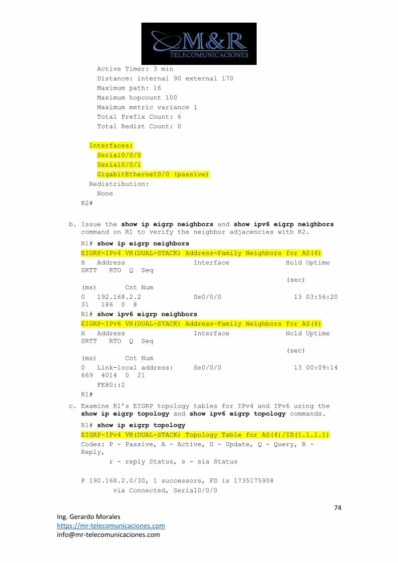
74 Ing. Gerardo Morales https://mr-telecomunicaciones.com [email protected]
Active Timer: 3 min
Distance: internal 90 external 170
Maximum path: 16
Maximum hopcount 100
Maximum metric variance 1
Total Prefix Count: 6
Total Redist Count: 0
Interfaces:
Serial0/0/0
Serial0/0/1
GigabitEthernet0/0 (passive)
Redistribution:
None
R2#
b. Issue the show ip eigrp neighbors and show ipv6 eigrp neighbors command on R1 to verify the neighbor adjacencies with R2.
R1# show ip eigrp neighbors
EIGRP-IPv4 VR(DUAL-STACK) Address-Family Neighbors for AS(4)
H Address Interface Hold Uptime
SRTT RTO Q Seq
(sec)
(ms) Cnt Num
0 192.168.2.2 Se0/0/0 13 03:56:20
31 186 0 8
R1# show ipv6 eigrp neighbors
EIGRP-IPv6 VR(DUAL-STACK) Address-Family Neighbors for AS(6)
H Address Interface Hold Uptime
SRTT RTO Q Seq
(sec)
(ms) Cnt Num
0 Link-local address: Se0/0/0 13 00:09:14
669 4014 0 21
FE80::2
R1#
c. Examine R1’s EIGRP topology tables for IPv4 and IPv6 using the show ip eigrp topology and show ipv6 eigrp topology commands.
R1# show ip eigrp topology
EIGRP-IPv4 VR(DUAL-STACK) Topology Table for AS(4)/ID(1.1.1.1)
Codes: P - Passive, A - Active, U - Update, Q - Query, R -
Reply,
r - reply Status, s - sia Status
P 192.168.2.0/30, 1 successors, FD is 1735175958
via Connected, Serial0/0/0
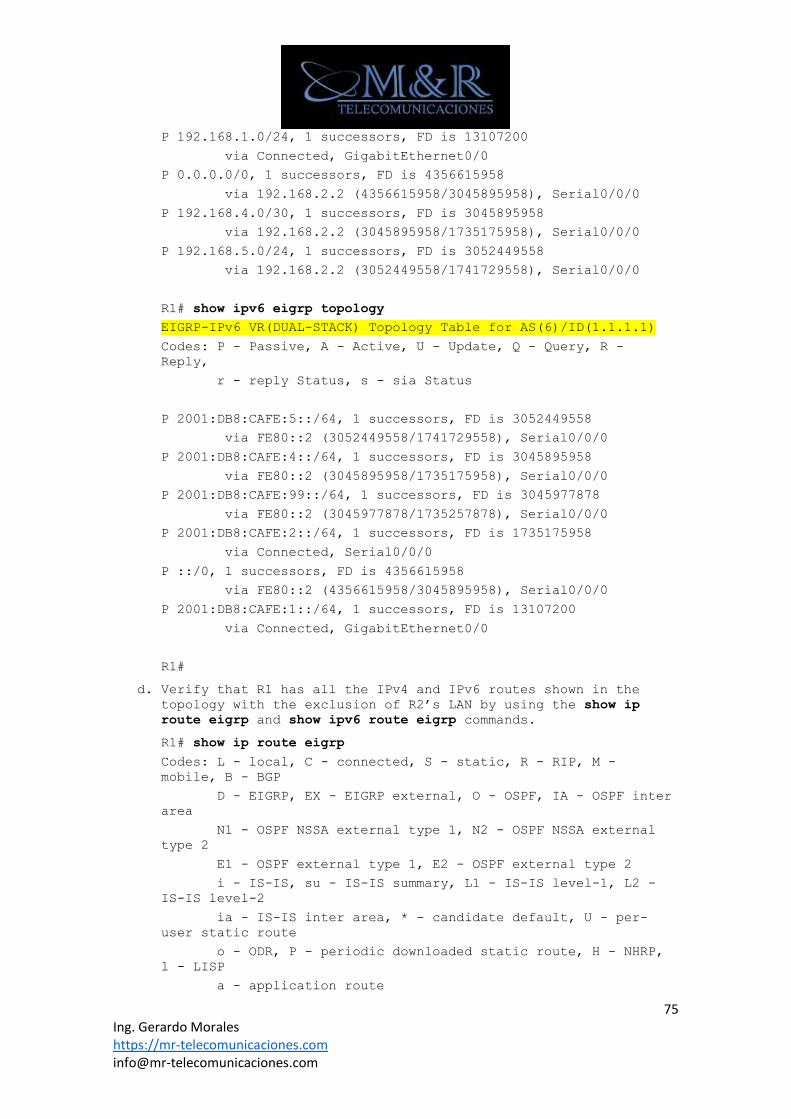
75 Ing. Gerardo Morales https://mr-telecomunicaciones.com [email protected]
P 192.168.1.0/24, 1 successors, FD is 13107200
via Connected, GigabitEthernet0/0
P 0.0.0.0/0, 1 successors, FD is 4356615958
via 192.168.2.2 (4356615958/3045895958), Serial0/0/0
P 192.168.4.0/30, 1 successors, FD is 3045895958
via 192.168.2.2 (3045895958/1735175958), Serial0/0/0
P 192.168.5.0/24, 1 successors, FD is 3052449558
via 192.168.2.2 (3052449558/1741729558), Serial0/0/0
R1# show ipv6 eigrp topology
EIGRP-IPv6 VR(DUAL-STACK) Topology Table for AS(6)/ID(1.1.1.1)
Codes: P - Passive, A - Active, U - Update, Q - Query, R -
Reply,
r - reply Status, s - sia Status
P 2001:DB8:CAFE:5::/64, 1 successors, FD is 3052449558
via FE80::2 (3052449558/1741729558), Serial0/0/0
P 2001:DB8:CAFE:4::/64, 1 successors, FD is 3045895958
via FE80::2 (3045895958/1735175958), Serial0/0/0
P 2001:DB8:CAFE:99::/64, 1 successors, FD is 3045977878
via FE80::2 (3045977878/1735257878), Serial0/0/0
P 2001:DB8:CAFE:2::/64, 1 successors, FD is 1735175958
via Connected, Serial0/0/0
P ::/0, 1 successors, FD is 4356615958
via FE80::2 (4356615958/3045895958), Serial0/0/0
P 2001:DB8:CAFE:1::/64, 1 successors, FD is 13107200
via Connected, GigabitEthernet0/0
R1#
d. Verify that R1 has all the IPv4 and IPv6 routes shown in the topology with the exclusion of R2’s LAN by using the show ip
route eigrp and show ipv6 route eigrp commands.
R1# show ip route eigrp
Codes: L - local, C - connected, S - static, R - RIP, M -
mobile, B - BGP
D - EIGRP, EX - EIGRP external, O - OSPF, IA - OSPF inter
area
N1 - OSPF NSSA external type 1, N2 - OSPF NSSA external
type 2
E1 - OSPF external type 1, E2 - OSPF external type 2
i - IS-IS, su - IS-IS summary, L1 - IS-IS level-1, L2 -
IS-IS level-2
ia - IS-IS inter area, * - candidate default, U - per-
user static route
o - ODR, P - periodic downloaded static route, H - NHRP,
l - LISP
a - application route
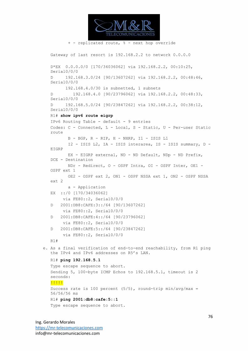
76 Ing. Gerardo Morales https://mr-telecomunicaciones.com [email protected]
+ - replicated route, % - next hop override
Gateway of last resort is 192.168.2.2 to network 0.0.0.0
D*EX 0.0.0.0/0 [170/34036062] via 192.168.2.2, 00:10:25,
Serial0/0/0
D 192.168.3.0/24 [90/13607262] via 192.168.2.2, 00:48:46,
Serial0/0/0
192.168.4.0/30 is subnetted, 1 subnets
D 192.168.4.0 [90/23796062] via 192.168.2.2, 00:48:33,
Serial0/0/0
D 192.168.5.0/24 [90/23847262] via 192.168.2.2, 00:38:12,
Serial0/0/0
R1# show ipv6 route eigrp
IPv6 Routing Table - default - 9 entries
Codes: C - Connected, L - Local, S - Static, U - Per-user Static
route
B - BGP, R - RIP, H - NHRP, I1 - ISIS L1
I2 - ISIS L2, IA - ISIS interarea, IS - ISIS summary, D -
EIGRP
EX - EIGRP external, ND - ND Default, NDp - ND Prefix,
DCE - Destination
NDr - Redirect, O - OSPF Intra, OI - OSPF Inter, OE1 -
OSPF ext 1
OE2 - OSPF ext 2, ON1 - OSPF NSSA ext 1, ON2 - OSPF NSSA
ext 2
a - Application
EX ::/0 [170/34036062]
via FE80::2, Serial0/0/0
D 2001:DB8:CAFE:3::/64 [90/13607262]
via FE80::2, Serial0/0/0
D 2001:DB8:CAFE:4::/64 [90/23796062]
via FE80::2, Serial0/0/0
D 2001:DB8:CAFE:5::/64 [90/23847262]
via FE80::2, Serial0/0/0
R1#
e. As a final verification of end-to-end reachability, from R1 ping the IPv4 and IPv6 addresses on R5’s LAN.
R1# ping 192.168.5.1
Type escape sequence to abort.
Sending 5, 100-byte ICMP Echos to 192.168.5.1, timeout is 2
seconds:
!!!!!
Success rate is 100 percent (5/5), round-trip min/avg/max =
56/56/56 ms
R1# ping 2001:db8:cafe:5::1
Type escape sequence to abort.
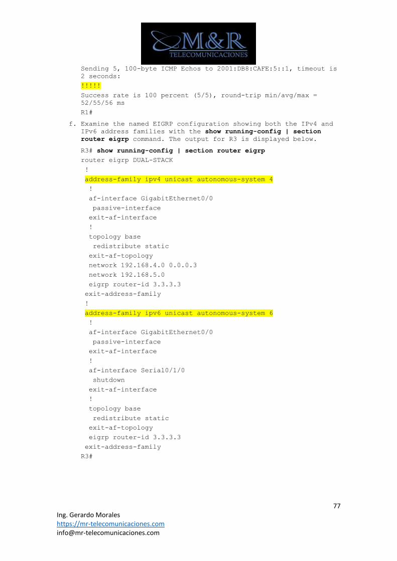
77 Ing. Gerardo Morales https://mr-telecomunicaciones.com [email protected]
Sending 5, 100-byte ICMP Echos to 2001:DB8:CAFE:5::1, timeout is
2 seconds:
!!!!!
Success rate is 100 percent (5/5), round-trip min/avg/max =
52/55/56 ms
R1#
f. Examine the named EIGRP configuration showing both the IPv4 and IPv6 address families with the show running-config | section
router eigrp command. The output for R3 is displayed below.
R3# show running-config | section router eigrp
router eigrp DUAL-STACK
!
address-family ipv4 unicast autonomous-system 4
!
af-interface GigabitEthernet0/0
passive-interface
exit-af-interface
!
topology base
redistribute static
exit-af-topology
network 192.168.4.0 0.0.0.3
network 192.168.5.0
eigrp router-id 3.3.3.3
exit-address-family
!
address-family ipv6 unicast autonomous-system 6
!
af-interface GigabitEthernet0/0
passive-interface
exit-af-interface
!
af-interface Serial0/1/0
shutdown
exit-af-interface
!
topology base
redistribute static
exit-af-topology
eigrp router-id 3.3.3.3
exit-address-family
R3#
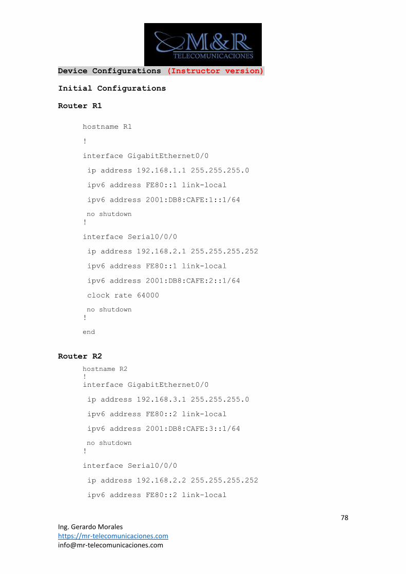
78 Ing. Gerardo Morales https://mr-telecomunicaciones.com [email protected]
Device Configurations (Instructor version)
Initial Configurations
Router R1
hostname R1
!
interface GigabitEthernet0/0
ip address 192.168.1.1 255.255.255.0
ipv6 address FE80::1 link-local
ipv6 address 2001:DB8:CAFE:1::1/64
no shutdown
!
interface Serial0/0/0
ip address 192.168.2.1 255.255.255.252
ipv6 address FE80::1 link-local
ipv6 address 2001:DB8:CAFE:2::1/64
clock rate 64000
no shutdown
!
end
Router R2
hostname R2
!
interface GigabitEthernet0/0
ip address 192.168.3.1 255.255.255.0
ipv6 address FE80::2 link-local
ipv6 address 2001:DB8:CAFE:3::1/64
no shutdown
!
interface Serial0/0/0
ip address 192.168.2.2 255.255.255.252
ipv6 address FE80::2 link-local
79 Ing. Gerardo Morales https://mr-telecomunicaciones.com [email protected]
ipv6 address 2001:DB8:CAFE:2::2/64
no shutdown
!
interface Serial0/0/1
ip address 192.168.4.1 255.255.255.252
ipv6 address FE80::2 link-local
ipv6 address 2001:DB8:CAFE:4::1/64
clock rate 64000
no shutdown
!
end
Router R3
hostname R3
!
interface GigabitEthernet0/0
ip address 192.168.5.1 255.255.255.0
ipv6 address FE80::3 link-local
ipv6 address 2001:DB8:CAFE:5::1/64
no shutdown
!
interface Serial0/0/1
ip address 192.168.4.2 255.255.255.252
ipv6 address FE80::3 link-local
ipv6 address 2001:DB8:CAFE:4::2/64
no shutdown
!
interface Serial0/1/0
ip address 192.168.77.2 255.255.255.0
ipv6 address FE80::3 link-local
ipv6 address 2001:DB8:FEED:77::2/64
clock rate 64000
no shutdown
!
end
Router R4
hostname R4
80 Ing. Gerardo Morales https://mr-telecomunicaciones.com [email protected]
!
interface Serial0/0/0
ip address 192.168.77.1 255.255.255.0
ipv6 address FE80::4 link-local
ipv6 address 2001:DB8:FEED:77::1/64
no shutdown
!
ipv6 route 2001:DB8:ABCD::/48 2001:DB8:FEED:77::2
ipv6 route 2001:DB8:CAFE::/48 2001:DB8:FEED:77::2
ip route 0.0.0.0 0.0.0.0 192.168.77.2
!
end
Final Configurations
Router R1
hostname R1
!
ipv6 unicast-routing
ip cef
ipv6 cef
!
interface GigabitEthernet0/0
ip address 192.168.1.1 255.255.255.0
ipv6 address FE80::1 link-local
ipv6 address 2001:DB8:CAFE:1::1/64
!
interface Serial0/0/0
ip address 192.168.2.1 255.255.255.252
ipv6 address FE80::1 link-local
ipv6 address 2001:DB8:CAFE:2::1/64
clock rate 64000
!
router eigrp DUAL-STACK
!
address-family ipv4 unicast autonomous-system 4
!
af-interface GigabitEthernet0/0
passive-interface
exit-af-interface
!
topology base
exit-af-topology
network 192.168.1.0
network 192.168.2.0 0.0.0.3
eigrp router-id 1.1.1.1
exit-address-family
!
address-family ipv6 unicast autonomous-system 6
!
af-interface GigabitEthernet0/0
passive-interface
exit-af-interface
!
topology base
81 Ing. Gerardo Morales https://mr-telecomunicaciones.com [email protected]
exit-af-topology
eigrp router-id 1.1.1.1
exit-address-family
!
end
Router R2
hostname R2
!
ipv6 unicast-routing
ip cef
ipv6 cef
!
interface GigabitEthernet0/0
ip address 192.168.3.1 255.255.255.0
ipv6 address FE80::2 link-local
ipv6 address 2001:DB8:CAFE:3::1/64
!
interface Serial0/0/0
ip address 192.168.2.2 255.255.255.252
ipv6 address FE80::2 link-local
ipv6 address 2001:DB8:CAFE:2::2/64
!
interface Serial0/0/1
ip address 192.168.4.1 255.255.255.252
ipv6 address FE80::2 link-local
ipv6 address 2001:DB8:CAFE:4::1/64
clock rate 64000
!
router eigrp DUAL-STACK
!
address-family ipv4 unicast autonomous-system 4
!
af-interface GigabitEthernet0/0
passive-interface
exit-af-interface
!
topology base
exit-af-topology
network 192.168.2.0 0.0.0.3
network 192.168.3.0
network 192.168.4.0 0.0.0.3
eigrp router-id 2.2.2.2
exit-address-family
!
address-family ipv6 unicast autonomous-system 6
!
af-interface GigabitEthernet0/0
passive-interface
exit-af-interface
!
topology base
exit-af-topology
eigrp router-id 2.2.2.2
82 Ing. Gerardo Morales https://mr-telecomunicaciones.com [email protected]
exit-address-family
!
end
Router R3
hostname R3
!
ipv6 unicast-routing
ip cef
ipv6 cef
!
interface GigabitEthernet0/0
ip address 192.168.5.1 255.255.255.0
ipv6 address FE80::3 link-local
ipv6 address 2001:DB8:CAFE:5::1/64
!
interface Serial0/0/1
ip address 192.168.4.2 255.255.255.252
ipv6 address FE80::3 link-local
ipv6 address 2001:DB8:CAFE:4::2/64
!
interface Serial0/1/0
ip address 192.168.77.2 255.255.255.0
ipv6 address FE80::3 link-local
ipv6 address 2001:DB8:FEED:77::2/64
clock rate 64000
!
router eigrp DUAL-STACK
!
address-family ipv4 unicast autonomous-system 4
!
af-interface GigabitEthernet0/0
passive-interface
exit-af-interface
!
topology base
redistribute static
exit-af-topology
network 192.168.4.0 0.0.0.3
network 192.168.5.0
eigrp router-id 3.3.3.3
exit-address-family
!
address-family ipv6 unicast autonomous-system 6
!
af-interface GigabitEthernet0/0
passive-interface
exit-af-interface
!
af-interface Serial0/1/0
shutdown
exit-af-interface
!
topology base
redistribute static
83 Ing. Gerardo Morales https://mr-telecomunicaciones.com [email protected]
exit-af-topology
eigrp router-id 3.3.3.3
exit-address-family
!
ip route 0.0.0.0 0.0.0.0 192.168.77.1
!
ipv6 route ::/0 Serial0/1/0 2001:DB8:FEED:77::1
!
end
Router R4
hostname R4
!
interface Serial0/0/0
ip address 192.168.77.1 255.255.255.0
ipv6 address FE80::4 link-local
ipv6 address 2001:DB8:FEED:77::1/64
!
ipv6 route 2001:DB8:CAFE::/48 2001:DB8:FEED:77::2
ip route 0.0.0.0 0.0.0.0 192.168.77.2
!
end
Chapter 2 Lab 2-3, EIGRP for IPv6 Instructor Version
Topology
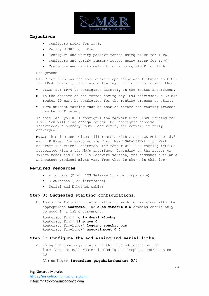
84 Ing. Gerardo Morales https://mr-telecomunicaciones.com [email protected]
Objectives
• Configure EIGRP for IPv6.
• Verify EIGRP for IPv6.
• Configure and verify passive routes using EIGRP for IPv6.
• Configure and verify summary routes using EIGRP for IPv6.
• Configure and verify default route using EIGRP for IPv6.
Background
EIGRP for IPv6 has the same overall operation and features as EIGRP
for IPv4. However, there are a few major differences between them:
• EIGRP for IPv6 is configured directly on the router interfaces.
• In the absence of the router having any IPv4 addresses, a 32-bit
router ID must be configured for the routing process to start.
• IPv6 unicast routing must be enabled before the routing process
can be configured.
In this lab, you will configure the network with EIGRP routing for
IPv6. You will also assign router IDs, configure passive
interfaces, a summary route, and verify the network is fully
converged.
Note: This lab uses Cisco 1941 routers with Cisco IOS Release 15.2
with IP Base. The switches are Cisco WS-C2960-24TT-L with Fast
Ethernet interfaces, therefore the router will use routing metrics
associated with a 100 Mb/s interface. Depending on the router or
switch model and Cisco IOS Software version, the commands available
and output produced might vary from what is shown in this lab.
Required Resources
• 4 routers (Cisco IOS Release 15.2 or comparable)
• 3 switches (LAN interfaces)
• Serial and Ethernet cables
Step 0: Suggested starting configurations.
b. Apply the following configuration to each router along with the
appropriate hostname. The exec-timeout 0 0 command should only
be used in a lab environment.
Router(config)# no ip domain-lookup
Router(config)# line con 0
Router(config-line)# logging synchronous
Router(config-line)# exec-timeout 0 0
Step 1: Configure the addressing and serial links.
c. Using the topology, configure the IPv6 addresses on the
interfaces of each router including the loopback addresses on
R3.
R1(config)# interface gigabitethernet 0/0
85 Ing. Gerardo Morales https://mr-telecomunicaciones.com [email protected]
R1(config-if)# ipv6 address 2001:db8:cafe:1::1/64
R1(config-if)# ipv6 address fe80::1 link-local
R1(config-if)# no shutdown
R1(config-if)# exit
R1(config)# interface serial 0/0/0
R1(config-if)# ipv6 address 2001:db8:cafe:2::1/64
R1(config-if)# ipv6 address fe80::1 link-local
R1(config-if)# clock rate 64000
R1(config-if)# no shutdown
R1(config-if)# exit
R2(config)# interface serial 0/0/0
R2(config-if)# ipv6 address 2001:db8:cafe:2::2/64
R2(config-if)# ipv6 address fe80::2 link-local
R2(config-if)# no shutdown
R2(config-if)# exit
R2(config)# interface gigabitethernet 0/0
R2(config-if)# ipv6 address 2001:db8:cafe:3::1/64
R2(config-if)# ipv6 address fe80::2 link-local
R2(config-if)# no shutdown
R2(config)# interface serial 0/0/1
R2(config-if)# ipv6 address 2001:db8:cafe:4::1/64
R2(config-if)# ipv6 address fe80::2 link-local
R2(config-if)# clock rate 64000
R2(config-if)# no shutdown
R2(config-if)# exit
R3(config)# interface serial 0/0/1
86 Ing. Gerardo Morales https://mr-telecomunicaciones.com [email protected]
R3(config-if)# ipv6 address 2001:db8:cafe:4::2/64
R3(config-if)# ipv6 address fe80::3 link-local
R3(config-if)# no shutdown
R3(config-if)# exit
R3(config)# interface gigabitethernet 0/0
R3(config-if)# ipv6 address 2001:db8:cafe:5::1/64
R3(config-if)# ipv6 address fe80::3 link-local
R3(config-if)# no shutdown
R3(config-if)# exit
R3(config)# interface loopback 1
R3(config-if)# ipv6 address 2001:db8:abcd:1::1/64
R3(config-if)# exit
R3(config)# interface loopback 2
R3(config-if)# ipv6 address 2001:db8:abcd:2::1/64
R3(config-if)# exit
R3(config)# interface loopback 3
R3(config-if)# ipv6 address 2001:db8:abcd:3::1/64
R3(config-if)# exit
R3(config)# interface loopback 4
R3(config-if)# ipv6 address 2001:db8:abcd:4::1/64
R3(config-if)# exit
R3(config)# interface loopback 5
R3(config-if)# ipv6 address 2001:db8:abcd:5::1/64
R3(config-if)# exit
R3(config)# interface serial 0/1/0
R3(config-if)# ipv6 address 2001:db8:feed:77::2/64
R3(config-if)# ipv6 address fe80::3 link-local
R3(config-if)# clock rate 64000
R3(config-if)# no shutdown
R3(config-if)# exit
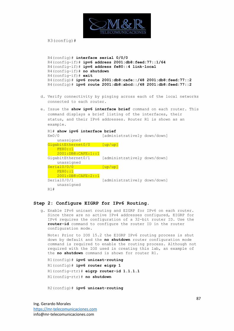
87 Ing. Gerardo Morales https://mr-telecomunicaciones.com [email protected]
R3(config)#
R4(config)# interface serial 0/0/0
R4(config-if)# ipv6 address 2001:db8:feed:77::1/64
R4(config-if)# ipv6 address fe80::4 link-local
R4(config-if)# no shutdown
R4(config-if)# exit
R4(config)# ipv6 route 2001:db8:cafe::/48 2001:db8:feed:77::2
R4(config)# ipv6 route 2001:db8:abcd::/48 2001:db8:feed:77::2
d. Verify connectivity by pinging across each of the local networks
connected to each router.
e. Issue the show ipv6 interface brief command on each router. This
command displays a brief listing of the interfaces, their
status, and their IPv6 addresses. Router R1 is shown as an
example.
R1# show ipv6 interface brief
Em0/0 [administratively down/down]
unassigned
GigabitEthernet0/0 [up/up]
FE80::1
2001:DB8:CAFE:1::1
GigabitEthernet0/1 [administratively down/down]
unassigned
Serial0/0/0 [up/up]
FE80::1
2001:DB8:CAFE:2::1
Serial0/0/1 [administratively down/down]
unassigned
R1#
Step 2: Configure EIGRP for IPv6 Routing.
g. Enable IPv6 unicast routing and EIGRP for IPv6 on each router. Since there are no active IPv4 addresses configured, EIGRP for
IPv6 requires the configuration of a 32-bit router ID. Use the
router-id command to configure the router ID in the router
configuration mode.
Note: Prior to IOS 15.2 the EIGRP IPv6 routing process is shut
down by default and the no shutdown router configuration mode
command is required to enable the routing process. Although not
required with the IOS used in creating this lab, an example of
the no shutdown command is shown for router R1.
R1(config)# ipv6 unicast-routing
R1(config)# ipv6 router eigrp 1
R1(config-rtr)# eigrp router-id 1.1.1.1
R1(config-rtr)# no shutdown
R2(config)# ipv6 unicast-routing
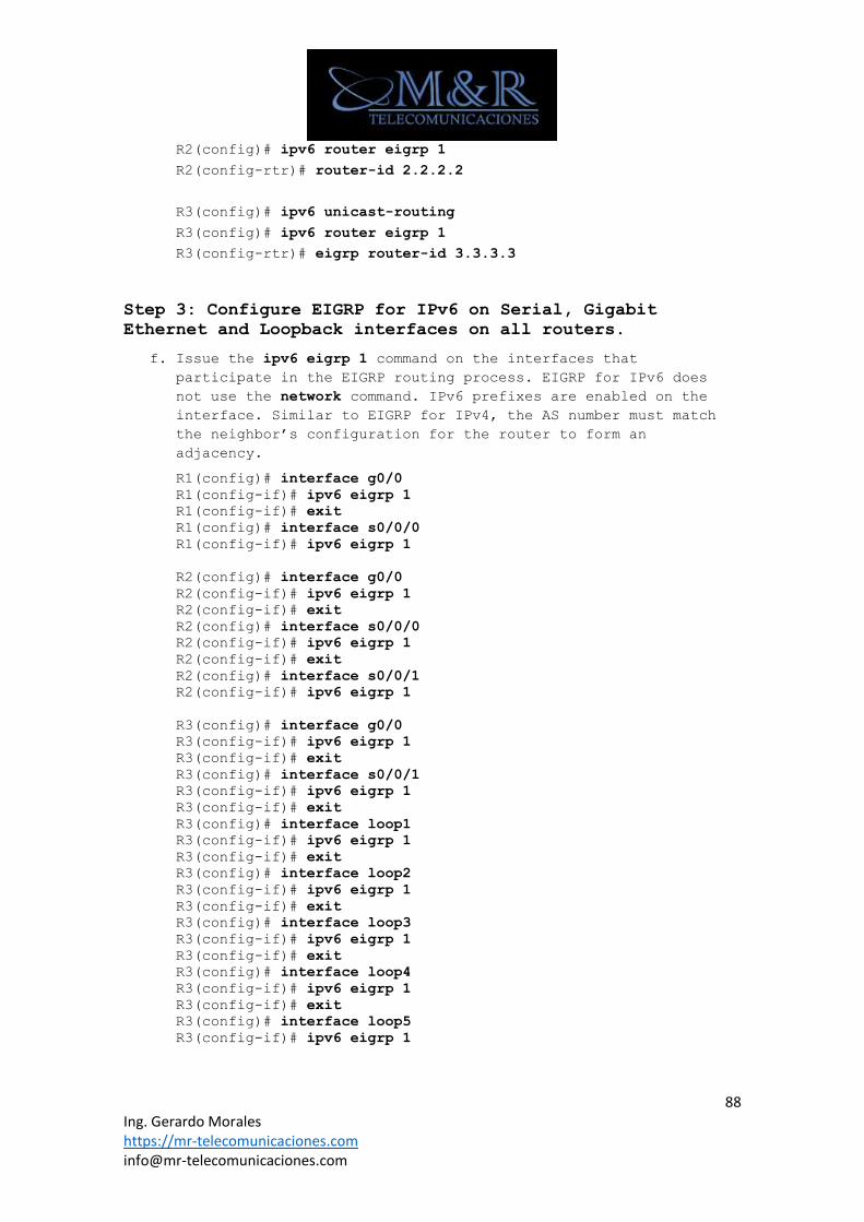
88 Ing. Gerardo Morales https://mr-telecomunicaciones.com [email protected]
R2(config)# ipv6 router eigrp 1
R2(config-rtr)# router-id 2.2.2.2
R3(config)# ipv6 unicast-routing
R3(config)# ipv6 router eigrp 1
R3(config-rtr)# eigrp router-id 3.3.3.3
Step 3: Configure EIGRP for IPv6 on Serial, Gigabit
Ethernet and Loopback interfaces on all routers.
f. Issue the ipv6 eigrp 1 command on the interfaces that
participate in the EIGRP routing process. EIGRP for IPv6 does
not use the network command. IPv6 prefixes are enabled on the
interface. Similar to EIGRP for IPv4, the AS number must match
the neighbor’s configuration for the router to form an
adjacency.
R1(config)# interface g0/0
R1(config-if)# ipv6 eigrp 1
R1(config-if)# exit
R1(config)# interface s0/0/0
R1(config-if)# ipv6 eigrp 1
R2(config)# interface g0/0
R2(config-if)# ipv6 eigrp 1
R2(config-if)# exit
R2(config)# interface s0/0/0
R2(config-if)# ipv6 eigrp 1
R2(config-if)# exit
R2(config)# interface s0/0/1
R2(config-if)# ipv6 eigrp 1
R3(config)# interface g0/0
R3(config-if)# ipv6 eigrp 1
R3(config-if)# exit
R3(config)# interface s0/0/1
R3(config-if)# ipv6 eigrp 1
R3(config-if)# exit
R3(config)# interface loop1
R3(config-if)# ipv6 eigrp 1
R3(config-if)# exit
R3(config)# interface loop2
R3(config-if)# ipv6 eigrp 1
R3(config-if)# exit
R3(config)# interface loop3
R3(config-if)# ipv6 eigrp 1
R3(config-if)# exit
R3(config)# interface loop4
R3(config-if)# ipv6 eigrp 1
R3(config-if)# exit
R3(config)# interface loop5
R3(config-if)# ipv6 eigrp 1
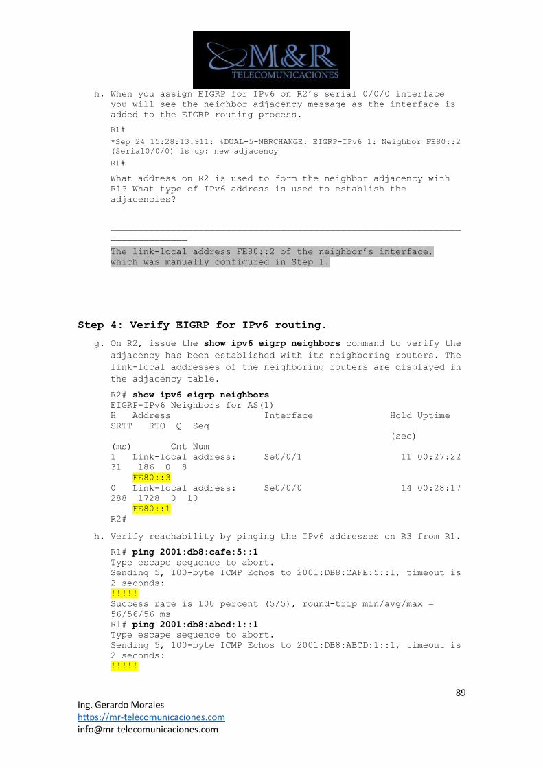
89 Ing. Gerardo Morales https://mr-telecomunicaciones.com [email protected]
h. When you assign EIGRP for IPv6 on R2’s serial 0/0/0 interface you will see the neighbor adjacency message as the interface is
added to the EIGRP routing process.
R1#
*Sep 24 15:28:13.911: %DUAL-5-NBRCHANGE: EIGRP-IPv6 1: Neighbor FE80::2
(Serial0/0/0) is up: new adjacency
R1#
What address on R2 is used to form the neighbor adjacency with
R1? What type of IPv6 address is used to establish the
adjacencies?
________________________________________________________________
______________
The link-local address FE80::2 of the neighbor’s interface,
which was manually configured in Step 1.
Step 4: Verify EIGRP for IPv6 routing.
g. On R2, issue the show ipv6 eigrp neighbors command to verify the
adjacency has been established with its neighboring routers. The
link-local addresses of the neighboring routers are displayed in
the adjacency table.
R2# show ipv6 eigrp neighbors
EIGRP-IPv6 Neighbors for AS(1)
H Address Interface Hold Uptime
SRTT RTO Q Seq
(sec)
(ms) Cnt Num
1 Link-local address: Se0/0/1 11 00:27:22
31 186 0 8
FE80::3
0 Link-local address: Se0/0/0 14 00:28:17
288 1728 0 10
FE80::1
R2#
h. Verify reachability by pinging the IPv6 addresses on R3 from R1.
R1# ping 2001:db8:cafe:5::1
Type escape sequence to abort.
Sending 5, 100-byte ICMP Echos to 2001:DB8:CAFE:5::1, timeout is
2 seconds:
!!!!!
Success rate is 100 percent (5/5), round-trip min/avg/max =
56/56/56 ms
R1# ping 2001:db8:abcd:1::1
Type escape sequence to abort.
Sending 5, 100-byte ICMP Echos to 2001:DB8:ABCD:1::1, timeout is
2 seconds:
!!!!!
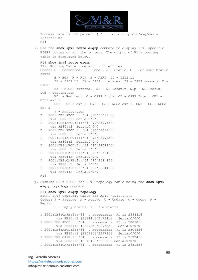
90 Ing. Gerardo Morales https://mr-telecomunicaciones.com [email protected]
Success rate is 100 percent (5/5), round-trip min/avg/max =
52/55/56 ms
R1#
i. Use the show ipv6 route eigrp command to display IPv6 specific
EIGRP routes on all the routers. The output of R1’s routing
table is displayed below.
R1# show ipv6 route eigrp
IPv6 Routing Table - default - 13 entries
Codes: C - Connected, L - Local, S - Static, U - Per-user Static
route
B - BGP, R - RIP, H - NHRP, I1 - ISIS L1
I2 - ISIS L2, IA - ISIS interarea, IS - ISIS summary, D -
EIGRP
EX - EIGRP external, ND - ND Default, NDp - ND Prefix,
DCE - Destination
NDr - Redirect, O - OSPF Intra, OI - OSPF Inter, OE1 -
OSPF ext 1
OE2 - OSPF ext 2, ON1 - OSPF NSSA ext 1, ON2 - OSPF NSSA
ext 2
a - Application
D 2001:DB8:ABCD:1::/64 [90/2809856]
via FE80::2, Serial0/0/0
D 2001:DB8:ABCD:2::/64 [90/2809856]
via FE80::2, Serial0/0/0
D 2001:DB8:ABCD:3::/64 [90/2809856]
via FE80::2, Serial0/0/0
D 2001:DB8:ABCD:4::/64 [90/2809856]
via FE80::2, Serial0/0/0
D 2001:DB8:ABCD:5::/64 [90/2809856]
via FE80::2, Serial0/0/0
D 2001:DB8:CAFE:3::/64 [90/2172416]
via FE80::2, Serial0/0/0
D 2001:DB8:CAFE:4::/64 [90/2681856]
via FE80::2, Serial0/0/0
D 2001:DB8:CAFE:5::/64 [90/2684416]
via FE80::2, Serial0/0/0
R1#
j. Examine R1’s EIGRP for IPv6 topology table using the show ipv6
eigrp topology command.
R1# show ipv6 eigrp topology
EIGRP-IPv6 Topology Table for AS(1)/ID(1.1.1.1)
Codes: P - Passive, A - Active, U - Update, Q - Query, R -
Reply,
r - reply Status, s - sia Status
P 2001:DB8:CAFE:5::/64, 1 successors, FD is 2684416
via FE80::2 (2684416/2172416), Serial0/0/0
P 2001:DB8:ABCD:1::/64, 1 successors, FD is 2809856
via FE80::2 (2809856/2297856), Serial0/0/0
P 2001:DB8:ABCD:2::/64, 1 successors, FD is 2809856
via FE80::2 (2809856/2297856), Serial0/0/0
P 2001:DB8:CAFE:3::/64, 1 successors, FD is 2172416
via FE80::2 (2172416/28160), Serial0/0/0
P 2001:DB8:CAFE:4::/64, 1 successors, FD is 2681856
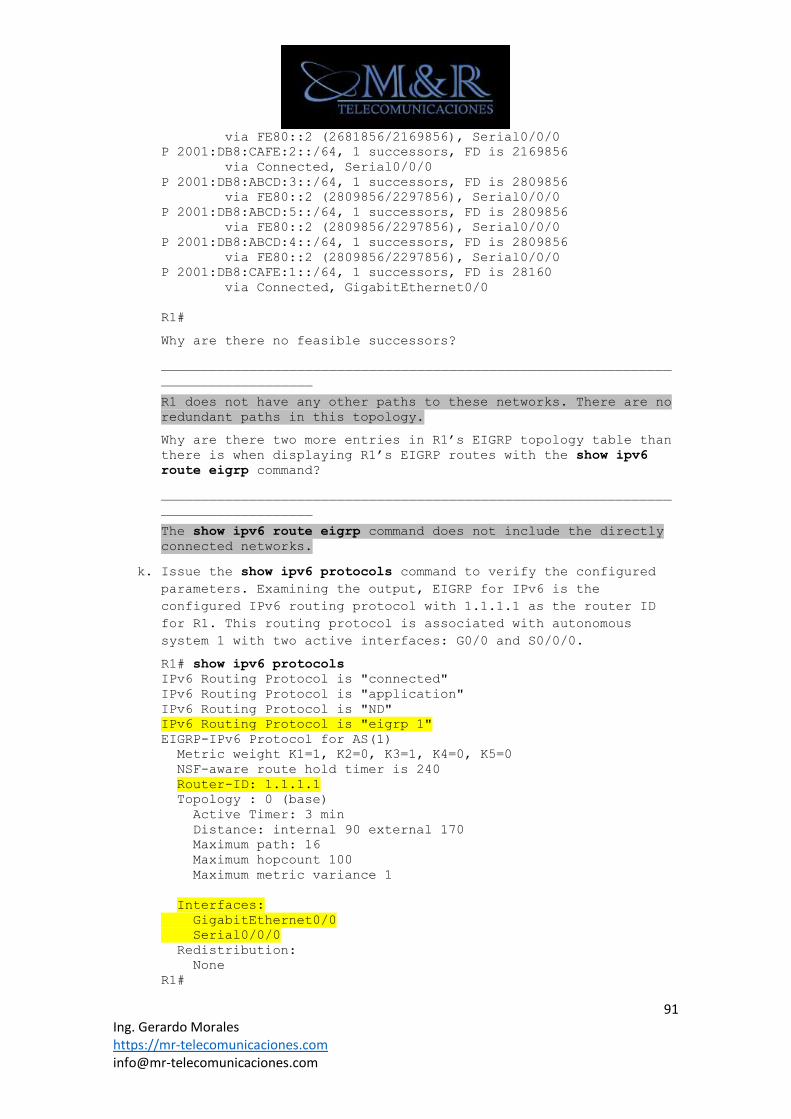
91 Ing. Gerardo Morales https://mr-telecomunicaciones.com [email protected]
via FE80::2 (2681856/2169856), Serial0/0/0
P 2001:DB8:CAFE:2::/64, 1 successors, FD is 2169856
via Connected, Serial0/0/0
P 2001:DB8:ABCD:3::/64, 1 successors, FD is 2809856
via FE80::2 (2809856/2297856), Serial0/0/0
P 2001:DB8:ABCD:5::/64, 1 successors, FD is 2809856
via FE80::2 (2809856/2297856), Serial0/0/0
P 2001:DB8:ABCD:4::/64, 1 successors, FD is 2809856
via FE80::2 (2809856/2297856), Serial0/0/0
P 2001:DB8:CAFE:1::/64, 1 successors, FD is 28160
via Connected, GigabitEthernet0/0
R1#
Why are there no feasible successors?
________________________________________________________________
___________________
R1 does not have any other paths to these networks. There are no
redundant paths in this topology.
Why are there two more entries in R1’s EIGRP topology table than
there is when displaying R1’s EIGRP routes with the show ipv6
route eigrp command?
________________________________________________________________
___________________
The show ipv6 route eigrp command does not include the directly
connected networks.
k. Issue the show ipv6 protocols command to verify the configured
parameters. Examining the output, EIGRP for IPv6 is the
configured IPv6 routing protocol with 1.1.1.1 as the router ID
for R1. This routing protocol is associated with autonomous
system 1 with two active interfaces: G0/0 and S0/0/0.
R1# show ipv6 protocols
IPv6 Routing Protocol is "connected"
IPv6 Routing Protocol is "application"
IPv6 Routing Protocol is "ND"
IPv6 Routing Protocol is "eigrp 1"
EIGRP-IPv6 Protocol for AS(1)
Metric weight K1=1, K2=0, K3=1, K4=0, K5=0
NSF-aware route hold timer is 240
Router-ID: 1.1.1.1
Topology : 0 (base)
Active Timer: 3 min
Distance: internal 90 external 170
Maximum path: 16
Maximum hopcount 100
Maximum metric variance 1
Interfaces:
GigabitEthernet0/0
Serial0/0/0
Redistribution:
None
R1#
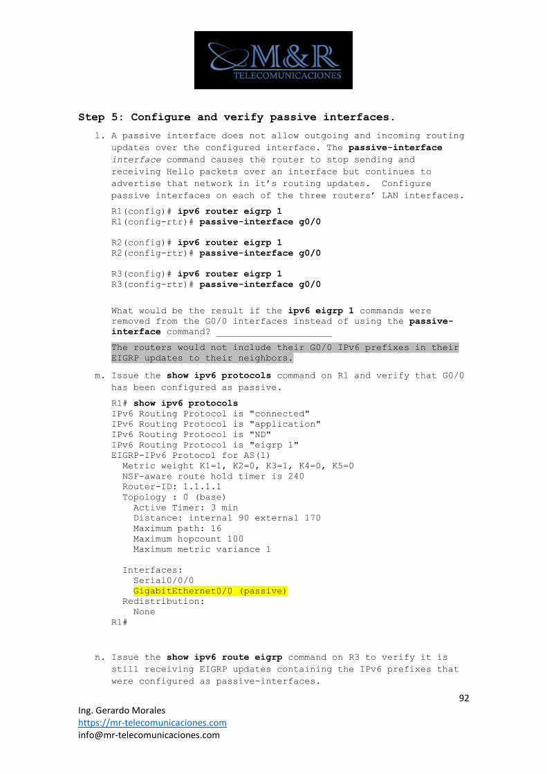
92 Ing. Gerardo Morales https://mr-telecomunicaciones.com [email protected]
Step 5: Configure and verify passive interfaces.
l. A passive interface does not allow outgoing and incoming routing
updates over the configured interface. The passive-interface
interface command causes the router to stop sending and
receiving Hello packets over an interface but continues to
advertise that network in it’s routing updates. Configure
passive interfaces on each of the three routers’ LAN interfaces.
R1(config)# ipv6 router eigrp 1
R1(config-rtr)# passive-interface g0/0
R2(config)# ipv6 router eigrp 1
R2(config-rtr)# passive-interface g0/0
R3(config)# ipv6 router eigrp 1
R3(config-rtr)# passive-interface g0/0
What would be the result if the ipv6 eigrp 1 commands were
removed from the G0/0 interfaces instead of using the passive-
interface command? _____________________
The routers would not include their G0/0 IPv6 prefixes in their
EIGRP updates to their neighbors.
m. Issue the show ipv6 protocols command on R1 and verify that G0/0
has been configured as passive.
R1# show ipv6 protocols
IPv6 Routing Protocol is "connected"
IPv6 Routing Protocol is "application"
IPv6 Routing Protocol is "ND"
IPv6 Routing Protocol is "eigrp 1"
EIGRP-IPv6 Protocol for AS(1)
Metric weight K1=1, K2=0, K3=1, K4=0, K5=0
NSF-aware route hold timer is 240
Router-ID: 1.1.1.1
Topology : 0 (base)
Active Timer: 3 min
Distance: internal 90 external 170
Maximum path: 16
Maximum hopcount 100
Maximum metric variance 1
Interfaces:
Serial0/0/0
GigabitEthernet0/0 (passive)
Redistribution:
None
R1#
n. Issue the show ipv6 route eigrp command on R3 to verify it is
still receiving EIGRP updates containing the IPv6 prefixes that
were configured as passive-interfaces.
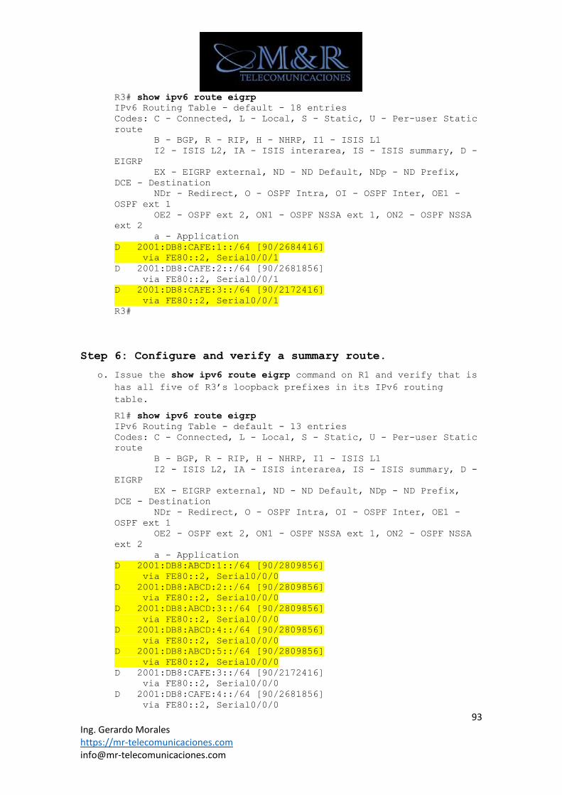
93 Ing. Gerardo Morales https://mr-telecomunicaciones.com [email protected]
R3# show ipv6 route eigrp
IPv6 Routing Table - default - 18 entries
Codes: C - Connected, L - Local, S - Static, U - Per-user Static
route
B - BGP, R - RIP, H - NHRP, I1 - ISIS L1
I2 - ISIS L2, IA - ISIS interarea, IS - ISIS summary, D -
EIGRP
EX - EIGRP external, ND - ND Default, NDp - ND Prefix,
DCE - Destination
NDr - Redirect, O - OSPF Intra, OI - OSPF Inter, OE1 -
OSPF ext 1
OE2 - OSPF ext 2, ON1 - OSPF NSSA ext 1, ON2 - OSPF NSSA
ext 2
a - Application
D 2001:DB8:CAFE:1::/64 [90/2684416]
via FE80::2, Serial0/0/1
D 2001:DB8:CAFE:2::/64 [90/2681856]
via FE80::2, Serial0/0/1
D 2001:DB8:CAFE:3::/64 [90/2172416]
via FE80::2, Serial0/0/1
R3#
Step 6: Configure and verify a summary route.
o. Issue the show ipv6 route eigrp command on R1 and verify that is
has all five of R3’s loopback prefixes in its IPv6 routing
table.
R1# show ipv6 route eigrp
IPv6 Routing Table - default - 13 entries
Codes: C - Connected, L - Local, S - Static, U - Per-user Static
route
B - BGP, R - RIP, H - NHRP, I1 - ISIS L1
I2 - ISIS L2, IA - ISIS interarea, IS - ISIS summary, D -
EIGRP
EX - EIGRP external, ND - ND Default, NDp - ND Prefix,
DCE - Destination
NDr - Redirect, O - OSPF Intra, OI - OSPF Inter, OE1 -
OSPF ext 1
OE2 - OSPF ext 2, ON1 - OSPF NSSA ext 1, ON2 - OSPF NSSA
ext 2
a - Application
D 2001:DB8:ABCD:1::/64 [90/2809856]
via FE80::2, Serial0/0/0
D 2001:DB8:ABCD:2::/64 [90/2809856]
via FE80::2, Serial0/0/0
D 2001:DB8:ABCD:3::/64 [90/2809856]
via FE80::2, Serial0/0/0
D 2001:DB8:ABCD:4::/64 [90/2809856]
via FE80::2, Serial0/0/0
D 2001:DB8:ABCD:5::/64 [90/2809856]
via FE80::2, Serial0/0/0
D 2001:DB8:CAFE:3::/64 [90/2172416]
via FE80::2, Serial0/0/0
D 2001:DB8:CAFE:4::/64 [90/2681856]
via FE80::2, Serial0/0/0
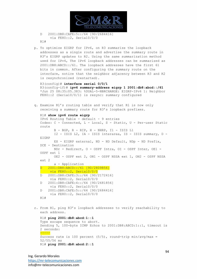
94 Ing. Gerardo Morales https://mr-telecomunicaciones.com [email protected]
D 2001:DB8:CAFE:5::/64 [90/2684416]
via FE80::2, Serial0/0/0
R1#
p. To optimize EIGRP for IPv6, on R3 summarize the loopback
addresses as a single route and advertise the summary route in
R3’s EIGRP updates to R2. Using the same summarization method
used for IPv4, The IPv6 loopback addresses can be summarized as
2001:DB8:ABCD::/61. The loopback addresses have the first 61
bits in common. After configuring the summary route on the
interface, notice that the neighbor adjacency between R3 and R2
is resynchronized (restarted).
R3(config)# interface serial 0/0/1
R3(config-if)# ipv6 summary-address eigrp 1 2001:db8:abcd::/61
*Jun 25 08:35:05.383: %DUAL-5-NBRCHANGE: EIGRP-IPv6 1: Neighbor
FE80::2 (Serial0/0/1) is resync: summary configured
q. Examine R1’s routing table and verify that R1 is now only
receiving a summary route for R3’s loopback prefixes.
R1# show ipv6 route eigrp
IPv6 Routing Table - default - 9 entries
Codes: C - Connected, L - Local, S - Static, U - Per-user Static
route
B - BGP, R - RIP, H - NHRP, I1 - ISIS L1
I2 - ISIS L2, IA - ISIS interarea, IS - ISIS summary, D -
EIGRP
EX - EIGRP external, ND - ND Default, NDp - ND Prefix,
DCE - Destination
NDr - Redirect, O - OSPF Intra, OI - OSPF Inter, OE1 -
OSPF ext 1
OE2 - OSPF ext 2, ON1 - OSPF NSSA ext 1, ON2 - OSPF NSSA
ext 2
a - Application
D 2001:DB8:ABCD::/61 [90/2809856]
via FE80::2, Serial0/0/0
D 2001:DB8:CAFE:3::/64 [90/2172416]
via FE80::2, Serial0/0/0
D 2001:DB8:CAFE:4::/64 [90/2681856]
via FE80::2, Serial0/0/0
D 2001:DB8:CAFE:5::/64 [90/2684416]
via FE80::2, Serial0/0/0
R1#
r. From R1, ping R3’s loopback addresses to verify reachability to
each address.
R1# ping 2001:db8:abcd:1::1
Type escape sequence to abort.
Sending 5, 100-byte ICMP Echos to 2001:DB8:ABCD:1::1, timeout is
2 seconds:
!!!!!
Success rate is 100 percent (5/5), round-trip min/avg/max =
52/55/56 ms
R1# ping 2001:db8:abcd:2::1
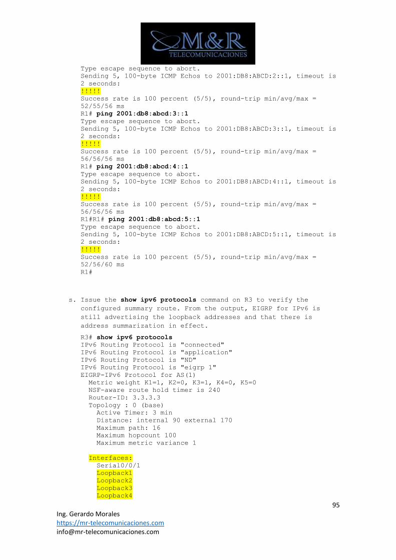
95 Ing. Gerardo Morales https://mr-telecomunicaciones.com [email protected]
Type escape sequence to abort.
Sending 5, 100-byte ICMP Echos to 2001:DB8:ABCD:2::1, timeout is
2 seconds:
!!!!!
Success rate is 100 percent (5/5), round-trip min/avg/max =
52/55/56 ms
R1# ping 2001:db8:abcd:3::1
Type escape sequence to abort.
Sending 5, 100-byte ICMP Echos to 2001:DB8:ABCD:3::1, timeout is
2 seconds:
!!!!!
Success rate is 100 percent (5/5), round-trip min/avg/max =
56/56/56 ms
R1# ping 2001:db8:abcd:4::1
Type escape sequence to abort.
Sending 5, 100-byte ICMP Echos to 2001:DB8:ABCD:4::1, timeout is
2 seconds:
!!!!!
Success rate is 100 percent (5/5), round-trip min/avg/max =
56/56/56 ms
R1#R1# ping 2001:db8:abcd:5::1
Type escape sequence to abort.
Sending 5, 100-byte ICMP Echos to 2001:DB8:ABCD:5::1, timeout is
2 seconds:
!!!!!
Success rate is 100 percent (5/5), round-trip min/avg/max =
52/56/60 ms
R1#
s. Issue the show ipv6 protocols command on R3 to verify the
configured summary route. From the output, EIGRP for IPv6 is
still advertising the loopback addresses and that there is
address summarization in effect.
R3# show ipv6 protocols
IPv6 Routing Protocol is "connected"
IPv6 Routing Protocol is "application"
IPv6 Routing Protocol is "ND"
IPv6 Routing Protocol is "eigrp 1"
EIGRP-IPv6 Protocol for AS(1)
Metric weight K1=1, K2=0, K3=1, K4=0, K5=0
NSF-aware route hold timer is 240
Router-ID: 3.3.3.3
Topology : 0 (base)
Active Timer: 3 min
Distance: internal 90 external 170
Maximum path: 16
Maximum hopcount 100
Maximum metric variance 1
Interfaces:
Serial0/0/1
Loopback1
Loopback2
Loopback3
Loopback4
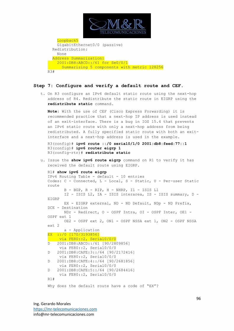
96 Ing. Gerardo Morales https://mr-telecomunicaciones.com [email protected]
Loopback5
GigabitEthernet0/0 (passive)
Redistribution:
None
Address Summarization:
2001:DB8:ABCD::/61 for Se0/0/1
Summarizing 5 components with metric 128256
R3#
Step 7: Configure and verify a default route and CEF.
t. On R3 configure an IPv6 default static route using the next-hop
address of R4. Redistribute the static route in EIGRP using the
redistribute static command.
Note: With the use of CEF (Cisco Express Forwarding) it is
recommended practice that a next-hop IP address is used instead
of an exit-interface. There is a bug in IOS 15.4 that prevents
an IPv6 static route with only a next-hop address from being
redistributed. A fully specified static route with both an exit-
interface and a next-hop address is used in the example.
R3(config)# ipv6 route ::/0 serial0/1/0 2001:db8:feed:77::1
R3(config)# ipv6 router eigrp 1
R3(config-rtr)# redistribute static
u. Issue the show ipv6 route eigrp command on R1 to verify it has
received the default route using EIGRP.
R1# show ipv6 route eigrp
IPv6 Routing Table - default - 10 entries
Codes: C - Connected, L - Local, S - Static, U - Per-user Static
route
B - BGP, R - RIP, H - NHRP, I1 - ISIS L1
I2 - ISIS L2, IA - ISIS interarea, IS - ISIS summary, D -
EIGRP
EX - EIGRP external, ND - ND Default, NDp - ND Prefix,
DCE - Destination
NDr - Redirect, O - OSPF Intra, OI - OSPF Inter, OE1 -
OSPF ext 1
OE2 - OSPF ext 2, ON1 - OSPF NSSA ext 1, ON2 - OSPF NSSA
ext 2
a - Application
EX ::/0 [170/3193856]
via FE80::2, Serial0/0/0
D 2001:DB8:ABCD::/61 [90/2809856]
via FE80::2, Serial0/0/0
D 2001:DB8:CAFE:3::/64 [90/2172416]
via FE80::2, Serial0/0/0
D 2001:DB8:CAFE:4::/64 [90/2681856]
via FE80::2, Serial0/0/0
D 2001:DB8:CAFE:5::/64 [90/2684416]
via FE80::2, Serial0/0/0
R1#
Why does the default route have a code of “EX”?
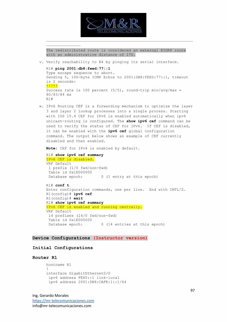
97 Ing. Gerardo Morales https://mr-telecomunicaciones.com [email protected]
________________________________________________________________
_______________
The redistributed route is considered an external EIGRP route
with an administrative distance of 170.
v. Verify reachability to R4 by pinging its serial interface.
R1# ping 2001:db8:feed:77::1
Type escape sequence to abort.
Sending 5, 100-byte ICMP Echos to 2001:DB8:FEED:77::1, timeout
is 2 seconds:
!!!!!
Success rate is 100 percent (5/5), round-trip min/avg/max =
80/83/84 ms
R1#
w. IPv6 Routing CEF is a forwarding mechanism to optimize the layer
3 and layer 2 lookup processes into a single process. Starting
with IOS 15.4 CEF for IPv6 is enabled automatically when ipv6
unicast-routing is configured. The show ipv6 cef command can be
used to verify the status of CEF for IPv6. If CEF is disabled,
it can be enabled with the ipv6 cef global configuration
command. The output below shows an example of CEF currently
disabled and then enabled.
Note: CEF for IPv4 is enabled by default.
R1# show ipv6 cef summary
IPv6 CEF is disabled.
VRF Default
1 prefix (1/0 fwd/non-fwd)
Table id 0x1E000000
Database epoch: 0 (1 entry at this epoch)
R1# conf t
Enter configuration commands, one per line. End with CNTL/Z.
R1(config)# ipv6 cef
R1(config)# exit
R1# show ipv6 cef summary
IPv6 CEF is enabled and running centrally.
VRF Default
14 prefixes (14/0 fwd/non-fwd)
Table id 0x1E000000
Database epoch: 0 (14 entries at this epoch)
Device Configurations (Instructor version)
Initial Configurations
Router R1
hostname R1
!
interface GigabitEthernet0/0
ipv6 address FE80::1 link-local
ipv6 address 2001:DB8:CAFE:1::1/64
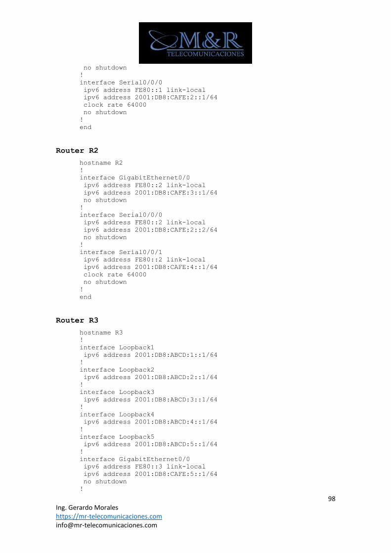
98 Ing. Gerardo Morales https://mr-telecomunicaciones.com [email protected]
no shutdown
!
interface Serial0/0/0
ipv6 address FE80::1 link-local
ipv6 address 2001:DB8:CAFE:2::1/64
clock rate 64000
no shutdown
!
end
Router R2
hostname R2
!
interface GigabitEthernet0/0
ipv6 address FE80::2 link-local
ipv6 address 2001:DB8:CAFE:3::1/64
no shutdown
!
interface Serial0/0/0
ipv6 address FE80::2 link-local
ipv6 address 2001:DB8:CAFE:2::2/64
no shutdown
!
interface Serial0/0/1
ipv6 address FE80::2 link-local
ipv6 address 2001:DB8:CAFE:4::1/64
clock rate 64000
no shutdown
!
end
Router R3
hostname R3
!
interface Loopback1
ipv6 address 2001:DB8:ABCD:1::1/64
!
interface Loopback2
ipv6 address 2001:DB8:ABCD:2::1/64
!
interface Loopback3
ipv6 address 2001:DB8:ABCD:3::1/64
!
interface Loopback4
ipv6 address 2001:DB8:ABCD:4::1/64
!
interface Loopback5
ipv6 address 2001:DB8:ABCD:5::1/64
!
interface GigabitEthernet0/0
ipv6 address FE80::3 link-local
ipv6 address 2001:DB8:CAFE:5::1/64
no shutdown
!
99 Ing. Gerardo Morales https://mr-telecomunicaciones.com [email protected]
interface Serial0/0/1
ipv6 address FE80::3 link-local
ipv6 address 2001:DB8:CAFE:4::2/64
no shutdown
!
interface Serial0/1/0
ipv6 address FE80::3 link-local
ipv6 address 2001:DB8:FEED:77::2/64
clock rate 64000
no shutdown
!
end
Router R4
hostname R4
!
interface Serial0/0/0
ipv6 address FE80::4 link-local
ipv6 address 2001:DB8:FEED:77::1/64
no shutdown
!
ipv6 route 2001:DB8:ABCD::/48 2001:DB8:FEED:77::2
ipv6 route 2001:DB8:CAFE::/48 2001:DB8:FEED:77::2
!
end
Final Configurations
Router R1
hostname R1
!
ipv6 unicast-routing
ipv6 cef
!
interface GigabitEthernet0/0
ipv6 address FE80::1 link-local
ipv6 address 2001:DB8:CAFE:1::1/64
ipv6 eigrp 1
!
interface Serial0/0/0
ipv6 address FE80::1 link-local
ipv6 address 2001:DB8:CAFE:2::1/64
ipv6 eigrp 1
clock rate 64000
!
ipv6 router eigrp 1
passive-interface GigabitEthernet0/0
eigrp router-id 1.1.1.1
!
end
100 Ing. Gerardo Morales https://mr-telecomunicaciones.com [email protected]
Router R2
hostname R2
!
ipv6 unicast-routing
ipv6 cef
!
interface GigabitEthernet0/0
ipv6 address FE80::2 link-local
ipv6 address 2001:DB8:CAFE:3::1/64
ipv6 eigrp 1
!
interface Serial0/0/0
ipv6 address FE80::2 link-local
ipv6 address 2001:DB8:CAFE:2::2/64
ipv6 eigrp 1
!
interface Serial0/0/1
ipv6 address FE80::2 link-local
ipv6 address 2001:DB8:CAFE:4::1/64
ipv6 eigrp 1
clock rate 64000
!
ipv6 router eigrp 1
passive-interface GigabitEthernet0/0
eigrp router-id 2.2.2.2
!
end
Router R3
hostname R3
!
ipv6 unicast-routing
ipv6 cef
!
interface Loopback1
ipv6 address 2001:DB8:ABCD:1::1/64
ipv6 eigrp 1
!
interface Loopback2
ipv6 address 2001:DB8:ABCD:2::1/64
ipv6 eigrp 1
!
interface Loopback3
ipv6 address 2001:DB8:ABCD:3::1/64
ipv6 eigrp 1
!
interface Loopback4
ipv6 address 2001:DB8:ABCD:4::1/64
ipv6 eigrp 1
!
interface Loopback5
ipv6 address 2001:DB8:ABCD:5::1/64
ipv6 eigrp 1
!
interface GigabitEthernet0/0
101 Ing. Gerardo Morales https://mr-telecomunicaciones.com [email protected]
ipv6 address FE80::3 link-local
ipv6 address 2001:DB8:CAFE:5::1/64
ipv6 eigrp 1
!
interface Serial0/0/1
ipv6 address FE80::3 link-local
ipv6 address 2001:DB8:CAFE:4::2/64
ipv6 eigrp 1
ipv6 summary-address eigrp 1 2001:DB8:ABCD::/61
!
interface Serial0/1/0
ipv6 address FE80::3 link-local
ipv6 address 2001:DB8:FEED:77::2/64
clock rate 64000
!
ipv6 route ::/0 Serial0/1/0 2001:DB8:FEED:77::1
ipv6 router eigrp 1
passive-interface GigabitEthernet0/0
eigrp router-id 3.3.3.3
redistribute static
!
end
Router R4
hostname R4
!
interface Serial0/0/0
ipv6 address FE80::4 link-local
ipv6 address 2001:DB8:FEED:77::1/64
!
ipv6 route 2001:DB8:ABCD::/48 2001:DB8:FEED:77::2
ipv6 route 2001:DB8:CAFE::/48 2001:DB8:FEED:77::2
!
end
OSPF V3
Show Commands
R1# show ipv6 ospf neighbor
R1# show ipv6 ospf database
R3# show ipv6 route ospf
Configurando Interfaces
Chapter 3 Lab 3-1, OSPF Virtual Links Instructor Version
Topology
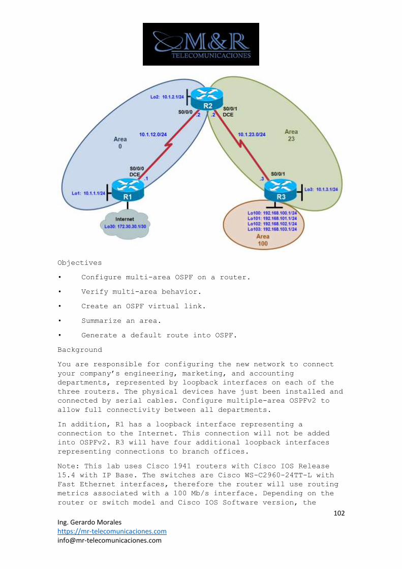
102 Ing. Gerardo Morales https://mr-telecomunicaciones.com [email protected]
Objectives
• Configure multi-area OSPF on a router.
• Verify multi-area behavior.
• Create an OSPF virtual link.
• Summarize an area.
• Generate a default route into OSPF.
Background
You are responsible for configuring the new network to connect
your company’s engineering, marketing, and accounting
departments, represented by loopback interfaces on each of the
three routers. The physical devices have just been installed and
connected by serial cables. Configure multiple-area OSPFv2 to
allow full connectivity between all departments.
In addition, R1 has a loopback interface representing a
connection to the Internet. This connection will not be added
into OSPFv2. R3 will have four additional loopback interfaces
representing connections to branch offices.
Note: This lab uses Cisco 1941 routers with Cisco IOS Release
15.4 with IP Base. The switches are Cisco WS-C2960-24TT-L with
Fast Ethernet interfaces, therefore the router will use routing
metrics associated with a 100 Mb/s interface. Depending on the
router or switch model and Cisco IOS Software version, the
103 Ing. Gerardo Morales https://mr-telecomunicaciones.com [email protected]
commands available and output produced might vary from what is
shown in this lab.
Required Resources
• 3 routers (Cisco IOS Release 15.2 or comparable)
• Serial and Ethernet cables
Step 0: Suggested starting configurations.
a. Apply the following configuration to each router along with
the appropriate hostname. The exec-timeout 0 0 command should
only be used in a lab environment.
Router(config)# no ip domain-lookup
Router(config)# line con 0
Router(config-line)# logging synchronous
Router(config-line)# exec-timeout 0 0
Step 1: Configure addressing and loopbacks.
Using the addressing scheme in the diagram, apply IP addresses
to the serial interfaces on R1, R2, and R3. Create loopbacks on
R1, R2, and R3, and address them according to the diagram.
R1# configure terminal
Enter configuration commands, one per line. End with CNTL/Z.
R1(config)# interface loopback 1
R1(config-if)# description Engineering Department
R1(config-if)# ip address 10.1.1.1 255.255.255.0
R1(config-if)# interface loopback 30
R1(config-if)# ip address 172.30.30.1 255.255.255.252
R1(config-if)# interface serial 0/0/0
R1(config-if)# ip address 10.1.12.1 255.255.255.0
R1(config-if)# clockrate 64000
R1(config-if)# no shutdown
R2# configure terminal
Enter configuration commands, one per line. End with CNTL/Z.
R2(config)# interface loopback 2
104 Ing. Gerardo Morales https://mr-telecomunicaciones.com [email protected]
R2(config-if)# description Marketing Department
R2(config-if)# ip address 10.1.2.1 255.255.255.0
R2(config-if)# interface serial 0/0/0
R2(config-if)# ip address 10.1.12.2 255.255.255.0
R2(config-if)# no shutdown
R2(config-if)# interface serial 0/0/1
R2(config-if)# ip address 10.1.23.2 255.255.255.0
R2(config-if)# clockrate 64000
R2(config-if)# no shutdown
R3# configure terminal
Enter configuration commands, one per line. End with CNTL/Z.
R3(config)# interface loopback 3
R3(config-if)# description Accounting Department
R3(config-if)# ip address 10.1.3.1 255.255.255.0
R3(config-if)# interface loopback 100
R3(config-if)# ip address 192.168.100.1 255.255.255.0
R3(config-if)# interface loopback 101
R3(config-if)# ip address 192.168.101.1 255.255.255.0
R3(config-if)# interface loopback 102
R3(config-if)# ip address 192.168.102.1 255.255.255.0
R3(config-if)# interface loopback 103
R3(config-if)# ip address 192.168.103.1 255.255.255.0
R3(config-if)# interface serial 0/0/1
R3(config-if)# ip address 10.1.23.3 255.255.255.0
R3(config-if)# no shutdown
Step 2: Add interfaces into OSPF.
a. Create OSPF process 1 and OSPF router ID on all three
routers. Using the network command, configure the subnet of the
serial link between R1 and R2 to be in OSPF area 0. Add loopback
1 on R1 and loopback 2 on R2 into OSPF area 0.
105 Ing. Gerardo Morales https://mr-telecomunicaciones.com [email protected]
Note: The default behavior of OSPF for loopback interfaces is to
advertise a 32-bit host route. To ensure that the full /24
network is advertised, use the ip ospf network point-to-point
command. Change the network type on the loopback interfaces so
that they are advertised with the correct subnet.
R1(config)# router ospf 1
R1(config-router)# router-id 1.1.1.1
R1(config-router)# network 10.1.12.0 0.0.0.255 area 0
R1(config-router)# network 10.1.1.0 0.0.0.255 area 0
R1(config-router)# exit
R1(config)# interface loopback 1
R1(config-if)# ip ospf network point-to-point
R1(config-if)# end
The show ip ospf command should be used to verify the OSPF
router ID. If the OSPF router ID is using a 32-bit value other
than the one specified by the router-id command, you can reset
the router ID by using the clear ip ospf pid process command and
re-verify using the command show ip ospf.
R1# show ip ospf
Routing Process "ospf 1" with ID 172.30.30.1
Start time: 04:19:23.024, Time elapsed: 00:31:01.416
Supports only single TOS(TOS0) routes
Supports opaque LSA
Supports Link-local Signaling (LLS)
Supports area transit capability
Supports NSSA (compatible with RFC 3101)
Event-log enabled, Maximum number of events: 1000, Mode: cyclic
Router is not originating router-LSAs with maximum metric
Initial SPF schedule delay 5000 msecs
Minimum hold time between two consecutive SPFs 10000 msecs
Maximum wait time between two consecutive SPFs 10000 msecs
106 Ing. Gerardo Morales https://mr-telecomunicaciones.com [email protected]
Incremental-SPF disabled
Minimum LSA interval 5 secs
Minimum LSA arrival 1000 msecs
LSA group pacing timer 240 secs
Interface flood pacing timer 33 msecs
Retransmission pacing timer 66 msecs
Number of external LSA 0. Checksum Sum 0x000000
Number of opaque AS LSA 0. Checksum Sum 0x000000
Number of DCbitless external and opaque AS LSA 0
Number of DoNotAge external and opaque AS LSA 0
Number of areas in this router is 1. 1 normal 0 stub 0 nssa
R1# clear ip ospf 1 process
Reset OSPF process 1? [no]: yes
R1# show ip ospf
Routing Process "ospf 1" with ID 1.1.1.1
Start time: 04:19:23.024, Time elapsed: 00:31:01.416
Supports only single TOS(TOS0) routes
Supports opaque LSA
Supports Link-local Signaling (LLS)
Supports area transit capability
Supports NSSA (compatible with RFC 3101)
Event-log enabled, Maximum number of events: 1000, Mode: cyclic
Router is not originating router-LSAs with maximum metric
Initial SPF schedule delay 5000 msecs
Minimum hold time between two consecutive SPFs 10000 msecs
Maximum wait time between two consecutive SPFs 10000 msecs
Incremental-SPF disabled
Minimum LSA interval 5 secs
Minimum LSA arrival 1000 msecs
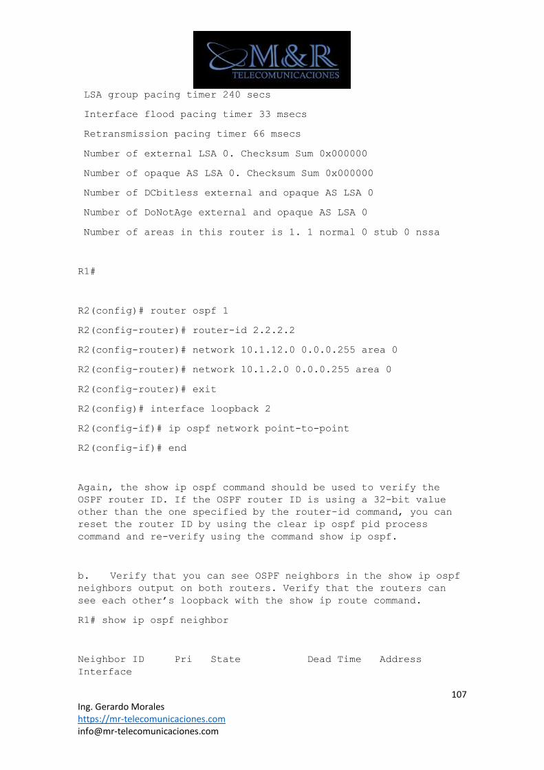
107 Ing. Gerardo Morales https://mr-telecomunicaciones.com [email protected]
LSA group pacing timer 240 secs
Interface flood pacing timer 33 msecs
Retransmission pacing timer 66 msecs
Number of external LSA 0. Checksum Sum 0x000000
Number of opaque AS LSA 0. Checksum Sum 0x000000
Number of DCbitless external and opaque AS LSA 0
Number of DoNotAge external and opaque AS LSA 0
Number of areas in this router is 1. 1 normal 0 stub 0 nssa
R1#
R2(config)# router ospf 1
R2(config-router)# router-id 2.2.2.2
R2(config-router)# network 10.1.12.0 0.0.0.255 area 0
R2(config-router)# network 10.1.2.0 0.0.0.255 area 0
R2(config-router)# exit
R2(config)# interface loopback 2
R2(config-if)# ip ospf network point-to-point
R2(config-if)# end
Again, the show ip ospf command should be used to verify the
OSPF router ID. If the OSPF router ID is using a 32-bit value
other than the one specified by the router-id command, you can
reset the router ID by using the clear ip ospf pid process
command and re-verify using the command show ip ospf.
b. Verify that you can see OSPF neighbors in the show ip ospf
neighbors output on both routers. Verify that the routers can
see each other’s loopback with the show ip route command.
R1# show ip ospf neighbor
Neighbor ID Pri State Dead Time Address
Interface
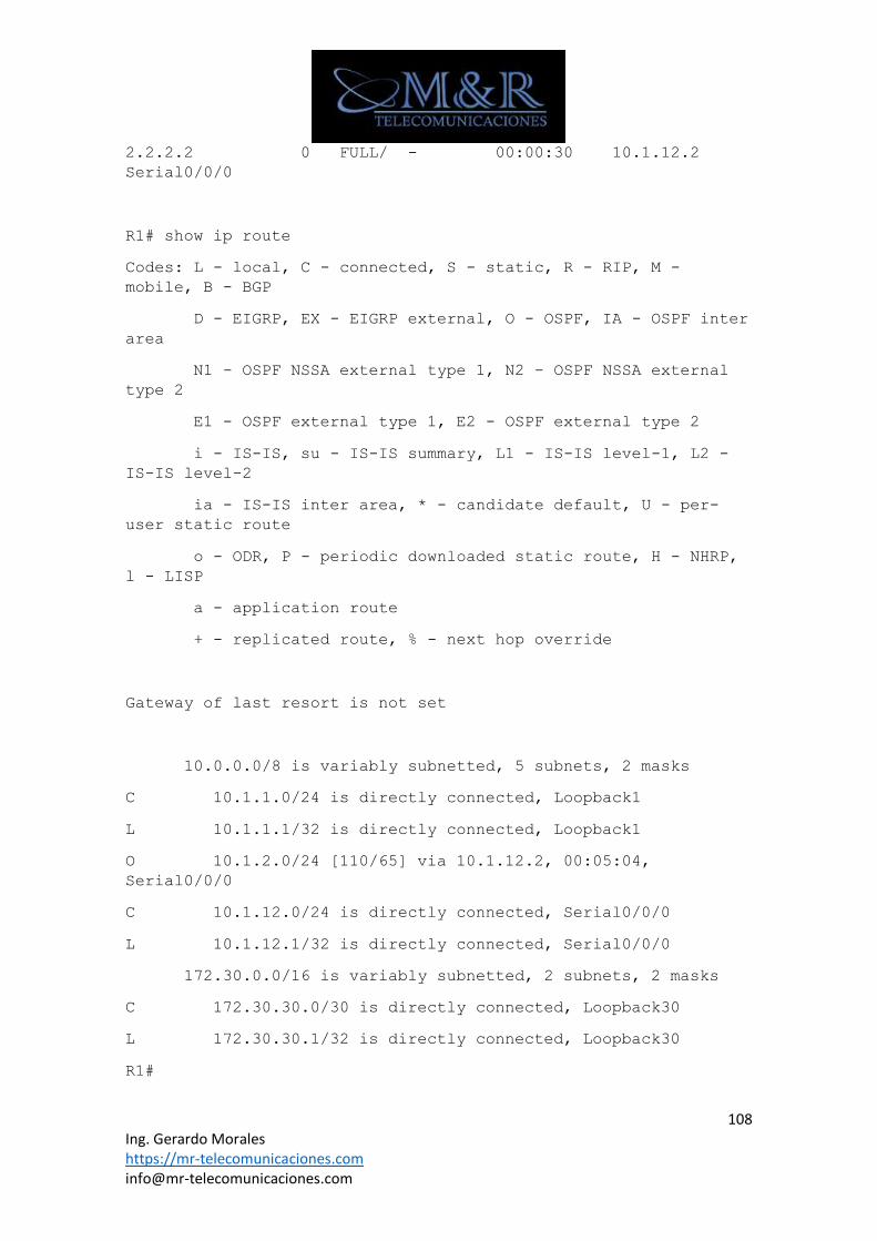
108 Ing. Gerardo Morales https://mr-telecomunicaciones.com [email protected]
2.2.2.2 0 FULL/ - 00:00:30 10.1.12.2
Serial0/0/0
R1# show ip route
Codes: L - local, C - connected, S - static, R - RIP, M -
mobile, B - BGP
D - EIGRP, EX - EIGRP external, O - OSPF, IA - OSPF inter
area
N1 - OSPF NSSA external type 1, N2 - OSPF NSSA external
type 2
E1 - OSPF external type 1, E2 - OSPF external type 2
i - IS-IS, su - IS-IS summary, L1 - IS-IS level-1, L2 -
IS-IS level-2
ia - IS-IS inter area, * - candidate default, U - per-
user static route
o - ODR, P - periodic downloaded static route, H - NHRP,
l - LISP
a - application route
+ - replicated route, % - next hop override
Gateway of last resort is not set
10.0.0.0/8 is variably subnetted, 5 subnets, 2 masks
C 10.1.1.0/24 is directly connected, Loopback1
L 10.1.1.1/32 is directly connected, Loopback1
O 10.1.2.0/24 [110/65] via 10.1.12.2, 00:05:04,
Serial0/0/0
C 10.1.12.0/24 is directly connected, Serial0/0/0
L 10.1.12.1/32 is directly connected, Serial0/0/0
172.30.0.0/16 is variably subnetted, 2 subnets, 2 masks
C 172.30.30.0/30 is directly connected, Loopback30
L 172.30.30.1/32 is directly connected, Loopback30
R1#
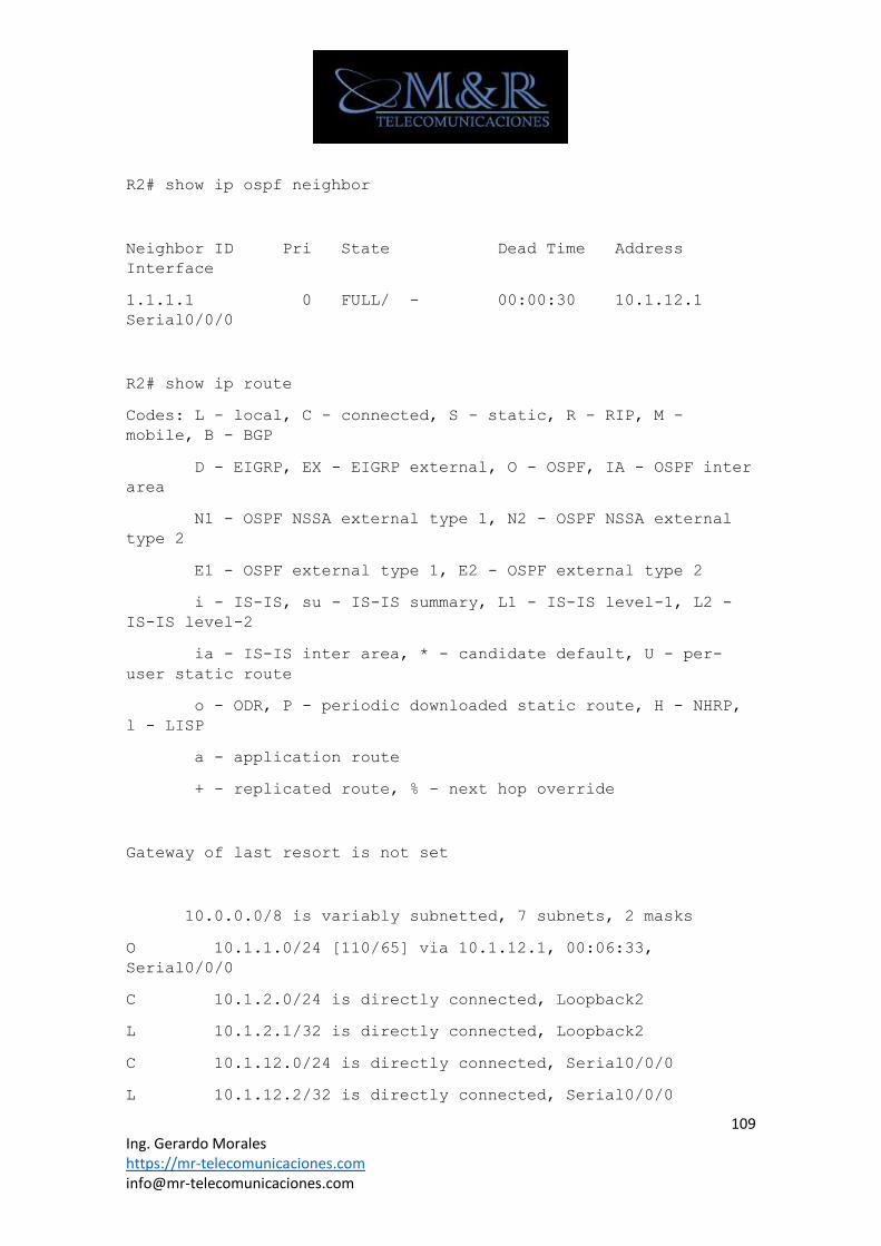
109 Ing. Gerardo Morales https://mr-telecomunicaciones.com [email protected]
R2# show ip ospf neighbor
Neighbor ID Pri State Dead Time Address
Interface
1.1.1.1 0 FULL/ - 00:00:30 10.1.12.1
Serial0/0/0
R2# show ip route
Codes: L - local, C - connected, S - static, R - RIP, M -
mobile, B - BGP
D - EIGRP, EX - EIGRP external, O - OSPF, IA - OSPF inter
area
N1 - OSPF NSSA external type 1, N2 - OSPF NSSA external
type 2
E1 - OSPF external type 1, E2 - OSPF external type 2
i - IS-IS, su - IS-IS summary, L1 - IS-IS level-1, L2 -
IS-IS level-2
ia - IS-IS inter area, * - candidate default, U - per-
user static route
o - ODR, P - periodic downloaded static route, H - NHRP,
l - LISP
a - application route
+ - replicated route, % - next hop override
Gateway of last resort is not set
10.0.0.0/8 is variably subnetted, 7 subnets, 2 masks
O 10.1.1.0/24 [110/65] via 10.1.12.1, 00:06:33,
Serial0/0/0
C 10.1.2.0/24 is directly connected, Loopback2
L 10.1.2.1/32 is directly connected, Loopback2
C 10.1.12.0/24 is directly connected, Serial0/0/0
L 10.1.12.2/32 is directly connected, Serial0/0/0
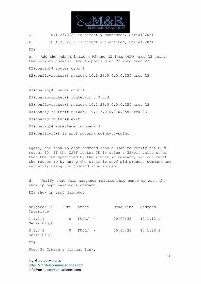
110 Ing. Gerardo Morales https://mr-telecomunicaciones.com [email protected]
C 10.1.23.0/24 is directly connected, Serial0/0/1
L 10.1.23.2/32 is directly connected, Serial0/0/1
R2#
c. Add the subnet between R2 and R3 into OSPF area 23 using
the network command. Add loopback 3 on R3 into area 23.
R2(config)# router ospf 1
R2(config-router)# network 10.1.23.0 0.0.0.255 area 23
R3(config)# router ospf 1
R3(config-router)# router-id 3.3.3.3
R3(config-router)# network 10.1.23.0 0.0.0.255 area 23
R3(config-router)# network 10.1.3.0 0.0.0.255 area 23
R3(config-router)# exit
R3(config)# interface loopback 3
R3(config-if)# ip ospf network point-to-point
Again, the show ip ospf command should used to verify the OSPF
router ID. If the OSPF router ID is using a 32-bit value other
than the one specified by the router-id command, you can reset
the router ID by using the clear ip ospf pid process command and
re-verify using the command show ip ospf.
d. Verify that this neighbor relationship comes up with the
show ip ospf neighbors command.
R2# show ip ospf neighbor
Neighbor ID Pri State Dead Time Address
Interface
1.1.1.1 0 FULL/ - 00:00:35 10.1.12.1
Serial0/0/0
3.3.3.3 0 FULL/ - 00:00:33 10.1.23.3
Serial0/0/1
R2#
Step 3: Create a virtual link.
111 Ing. Gerardo Morales https://mr-telecomunicaciones.com [email protected]
e. Add loopbacks 100 through 103 on R3 to R3’s OSPF process in
area 100 using the network command. Change the network type to
advertise the correct subnet mask.
R3(config)# router ospf 1
R3(config-router)# network 192.168.100.0 0.0.3.255 area 100
R3(config-router)# exit
R3(config)# interface loopback 100
R3(config-if)# ip ospf network point-to-point
R3(config-if)# interface loopback 101
R3(config-if)# ip ospf network point-to-point
R3(config-if)# interface loopback 102
R3(config-if)# ip ospf network point-to-point
R3(config-if)# interface loopback 103
R3(config-if)# ip ospf network point-to-point
f. Look at the output of the show ip route command on R2.
Notice that the routes to those networks do not appear. The
reason for this behavior is that area 100 on R3 is not connected
to the backbone. It is only connected to area 23. If an area is
not connected to the backbone, its routes are not advertised
outside of its area.
R2#show ip route
Codes: L - local, C - connected, S - static, R - RIP, M -
mobile, B - BGP
D - EIGRP, EX - EIGRP external, O - OSPF, IA - OSPF inter
area
N1 - OSPF NSSA external type 1, N2 - OSPF NSSA external
type 2
E1 - OSPF external type 1, E2 - OSPF external type 2
i - IS-IS, su - IS-IS summary, L1 - IS-IS level-1, L2 -
IS-IS level-2
ia - IS-IS inter area, * - candidate default, U - per-
user static route
o - ODR, P - periodic downloaded static route, H - NHRP,
l - LISP
a - application route
112 Ing. Gerardo Morales https://mr-telecomunicaciones.com [email protected]
+ - replicated route, % - next hop override
Gateway of last resort is not set
10.0.0.0/8 is variably subnetted, 8 subnets, 2 masks
O 10.1.1.0/24 [110/65] via 10.1.12.1, 00:09:22,
Serial0/0/0
C 10.1.2.0/24 is directly connected, Loopback2
L 10.1.2.1/32 is directly connected, Loopback2
O 10.1.3.0/24 [110/65] via 10.1.23.3, 00:08:03,
Serial0/0/1
C 10.1.12.0/24 is directly connected, Serial0/0/0
L 10.1.12.2/32 is directly connected, Serial0/0/0
C 10.1.23.0/24 is directly connected, Serial0/0/1
L 10.1.23.2/32 is directly connected, Serial0/0/1
R2#
What would happen if routes could pass between areas without
going through the backbone?
Routing loops might occur because any route could get advertised
to different areas. By passing through the backbone, type 3 LSAs
are generated by their respective areas and not sent back in.
You can get around this situation by creating a virtual link. A
virtual link is an OSPF feature that creates a logical extension
of the backbone area across a regular area, without actually
adding any physical interfaces into area 0.
Note: Prior to creating a virtual link you need to identify the
OSPF router ID for the routers involved (R2 and R3), using a
command such as show ip ospf, show ip protocols or show ip ospf
interface. The output for the show ip ospf command on R1 and R3
is shown below.
R2# show ip ospf
113 Ing. Gerardo Morales https://mr-telecomunicaciones.com [email protected]
Routing Process "ospf 1" with ID 2.2.2.2
<output omitted>
R3# show ip ospf
Routing Process "ospf 1" with ID 3.3.3.3
<output omitted>
g. Create a virtual link using the area transit_area virtual-
link router-id OSPF configuration command on both R2 and R3.
R2(config)# router ospf 1
R2(config-router)# area 23 virtual-link 3.3.3.3
R2(config-router)#
R3(config)# router ospf 1
R3(config-router)# area 23 virtual-link 2.2.2.2
*Aug 9 12:47:46.110: %OSPF-5-ADJCHG: Process 1, Nbr 2.2.2.2 on
OSPF_VL0 from LOADING to FULL, Loading Done
R3(config-router)#
Notice after virtual links are established IOS will report full
adjacency between both routers.
h. After you see the adjacency over the virtual interface come
up, issue the show ip route command on R2 and see the routes
from area 100. You can verify the virtual link with the show ip
ospf neighbor and show ip ospf interface commands.
R2# show ip route
Codes: L - local, C - connected, S - static, R - RIP, M -
mobile, B - BGP
D - EIGRP, EX - EIGRP external, O - OSPF, IA - OSPF inter
area
N1 - OSPF NSSA external type 1, N2 - OSPF NSSA external
type 2
E1 - OSPF external type 1, E2 - OSPF external type 2
i - IS-IS, su - IS-IS summary, L1 - IS-IS level-1, L2 -
IS-IS level-2
114 Ing. Gerardo Morales https://mr-telecomunicaciones.com [email protected]
ia - IS-IS inter area, * - candidate default, U - per-
user static route
o - ODR, P - periodic downloaded static route, H - NHRP,
l - LISP
a - application route
+ - replicated route, % - next hop override
Gateway of last resort is not set
10.0.0.0/8 is variably subnetted, 8 subnets, 2 masks
O 10.1.1.0/24 [110/65] via 10.1.12.1, 00:18:16,
Serial0/0/0
C 10.1.2.0/24 is directly connected, Loopback2
L 10.1.2.1/32 is directly connected, Loopback2
O 10.1.3.0/24 [110/65] via 10.1.23.3, 00:16:57,
Serial0/0/1
C 10.1.12.0/24 is directly connected, Serial0/0/0
L 10.1.12.2/32 is directly connected, Serial0/0/0
C 10.1.23.0/24 is directly connected, Serial0/0/1
L 10.1.23.2/32 is directly connected, Serial0/0/1
O IA 192.168.100.0/24 [110/65] via 10.1.23.3, 00:03:28,
Serial0/0/1
O IA 192.168.101.0/24 [110/65] via 10.1.23.3, 00:03:28,
Serial0/0/1
O IA 192.168.102.0/24 [110/65] via 10.1.23.3, 00:03:28,
Serial0/0/1
O IA 192.168.103.0/24 [110/65] via 10.1.23.3, 00:03:28,
Serial0/0/1
R2#
R2# show ip ospf neighbor
Neighbor ID Pri State Dead Time Address
Interface
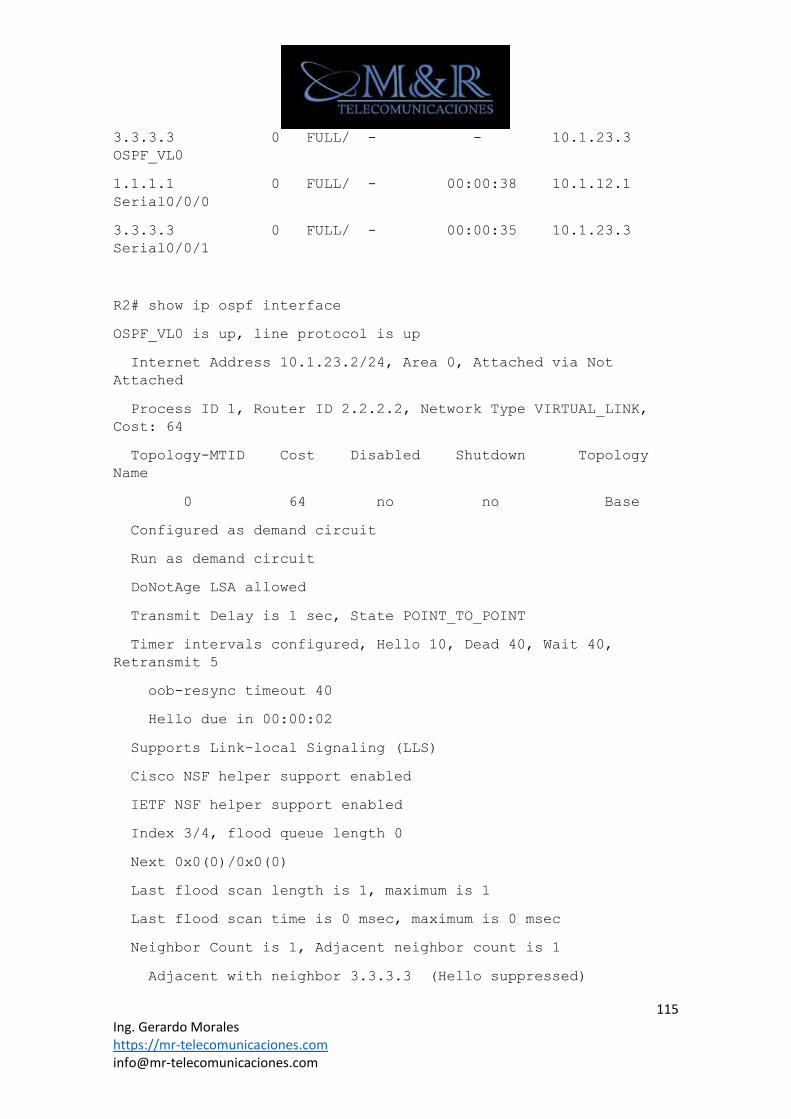
115 Ing. Gerardo Morales https://mr-telecomunicaciones.com [email protected]
3.3.3.3 0 FULL/ - - 10.1.23.3
OSPF_VL0
1.1.1.1 0 FULL/ - 00:00:38 10.1.12.1
Serial0/0/0
3.3.3.3 0 FULL/ - 00:00:35 10.1.23.3
Serial0/0/1
R2# show ip ospf interface
OSPF_VL0 is up, line protocol is up
Internet Address 10.1.23.2/24, Area 0, Attached via Not
Attached
Process ID 1, Router ID 2.2.2.2, Network Type VIRTUAL_LINK,
Cost: 64
Topology-MTID Cost Disabled Shutdown Topology
Name
0 64 no no Base
Configured as demand circuit
Run as demand circuit
DoNotAge LSA allowed
Transmit Delay is 1 sec, State POINT_TO_POINT
Timer intervals configured, Hello 10, Dead 40, Wait 40,
Retransmit 5
oob-resync timeout 40
Hello due in 00:00:02
Supports Link-local Signaling (LLS)
Cisco NSF helper support enabled
IETF NSF helper support enabled
Index 3/4, flood queue length 0
Next 0x0(0)/0x0(0)
Last flood scan length is 1, maximum is 1
Last flood scan time is 0 msec, maximum is 0 msec
Neighbor Count is 1, Adjacent neighbor count is 1
Adjacent with neighbor 3.3.3.3 (Hello suppressed)
116 Ing. Gerardo Morales https://mr-telecomunicaciones.com [email protected]
Suppress hello for 1 neighbor(s)
<output omitted>
When are virtual links useful?
Virtual links are useful when there needs to be a temporary
extension of the backbone, either because the backbone became
discontiguous or a new area got added onto an existing area.
Why are virtual links a poor long-term solution?
Virtual links are a poor long-term solution because they add
processing overhead and basically extend the backbone area onto
routers where it might not belong. They can also add a lot of
complexity to troubleshooting.
Step 4: Summarize an area.
Loopbacks 100 through 103 can be summarized into one supernet of
192.168.100.0 /22. You can configure area 100 to be represented
by this single summary route.
i. Configure R3 (the ABR) to summarize this area using the
area area range network mask command.
R3(config)# router ospf 1
R3(config-router)# area 100 range 192.168.100.0 255.255.252.0
j. You can see the summary route on R2 with the show ip route
and show ip ospf database commands.
R2#show ip route
Codes: L - local, C - connected, S - static, R - RIP, M -
mobile, B - BGP
D - EIGRP, EX - EIGRP external, O - OSPF, IA - OSPF inter
area
N1 - OSPF NSSA external type 1, N2 - OSPF NSSA external
type 2
E1 - OSPF external type 1, E2 - OSPF external type 2
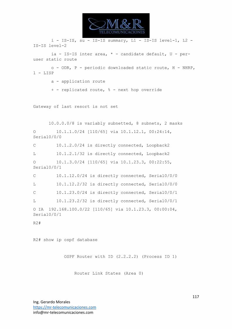
117 Ing. Gerardo Morales https://mr-telecomunicaciones.com [email protected]
i - IS-IS, su - IS-IS summary, L1 - IS-IS level-1, L2 -
IS-IS level-2
ia - IS-IS inter area, * - candidate default, U - per-
user static route
o - ODR, P - periodic downloaded static route, H - NHRP,
l - LISP
a - application route
+ - replicated route, % - next hop override
Gateway of last resort is not set
10.0.0.0/8 is variably subnetted, 8 subnets, 2 masks
O 10.1.1.0/24 [110/65] via 10.1.12.1, 00:24:14,
Serial0/0/0
C 10.1.2.0/24 is directly connected, Loopback2
L 10.1.2.1/32 is directly connected, Loopback2
O 10.1.3.0/24 [110/65] via 10.1.23.3, 00:22:55,
Serial0/0/1
C 10.1.12.0/24 is directly connected, Serial0/0/0
L 10.1.12.2/32 is directly connected, Serial0/0/0
C 10.1.23.0/24 is directly connected, Serial0/0/1
L 10.1.23.2/32 is directly connected, Serial0/0/1
O IA 192.168.100.0/22 [110/65] via 10.1.23.3, 00:00:04,
Serial0/0/1
R2#
R2# show ip ospf database
OSPF Router with ID (2.2.2.2) (Process ID 1)
Router Link States (Area 0)
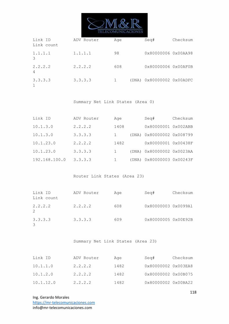
118 Ing. Gerardo Morales https://mr-telecomunicaciones.com [email protected]
Link ID ADV Router Age Seq# Checksum
Link count
1.1.1.1 1.1.1.1 98 0x80000006 0x00AA98
3
2.2.2.2 2.2.2.2 608 0x80000006 0x00AF0B
4
3.3.3.3 3.3.3.3 1 (DNA) 0x80000002 0x00ADFC
1
Summary Net Link States (Area 0)
Link ID ADV Router Age Seq# Checksum
10.1.3.0 2.2.2.2 1408 0x80000001 0x002ABB
10.1.3.0 3.3.3.3 1 (DNA) 0x80000002 0x008799
10.1.23.0 2.2.2.2 1482 0x80000001 0x00438F
10.1.23.0 3.3.3.3 1 (DNA) 0x80000002 0x0023AA
192.168.100.0 3.3.3.3 1 (DNA) 0x80000003 0x00243F
Router Link States (Area 23)
Link ID ADV Router Age Seq# Checksum
Link count
2.2.2.2 2.2.2.2 608 0x80000003 0x0099A1
2
3.3.3.3 3.3.3.3 609 0x80000005 0x00E92B
3
Summary Net Link States (Area 23)
Link ID ADV Router Age Seq# Checksum
10.1.1.0 2.2.2.2 1482 0x80000002 0x003EA8
10.1.2.0 2.2.2.2 1482 0x80000002 0x00B075
10.1.12.0 2.2.2.2 1482 0x80000002 0x00BA22
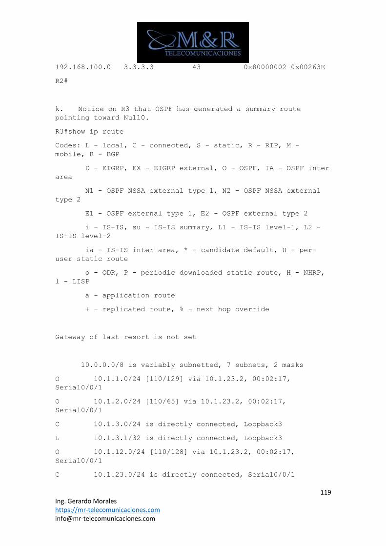
119 Ing. Gerardo Morales https://mr-telecomunicaciones.com [email protected]
192.168.100.0 3.3.3.3 43 0x80000002 0x00263E
R2#
k. Notice on R3 that OSPF has generated a summary route
pointing toward Null0.
R3#show ip route
Codes: L - local, C - connected, S - static, R - RIP, M -
mobile, B - BGP
D - EIGRP, EX - EIGRP external, O - OSPF, IA - OSPF inter
area
N1 - OSPF NSSA external type 1, N2 - OSPF NSSA external
type 2
E1 - OSPF external type 1, E2 - OSPF external type 2
i - IS-IS, su - IS-IS summary, L1 - IS-IS level-1, L2 -
IS-IS level-2
ia - IS-IS inter area, * - candidate default, U - per-
user static route
o - ODR, P - periodic downloaded static route, H - NHRP,
l - LISP
a - application route
+ - replicated route, % - next hop override
Gateway of last resort is not set
10.0.0.0/8 is variably subnetted, 7 subnets, 2 masks
O 10.1.1.0/24 [110/129] via 10.1.23.2, 00:02:17,
Serial0/0/1
O 10.1.2.0/24 [110/65] via 10.1.23.2, 00:02:17,
Serial0/0/1
C 10.1.3.0/24 is directly connected, Loopback3
L 10.1.3.1/32 is directly connected, Loopback3
O 10.1.12.0/24 [110/128] via 10.1.23.2, 00:02:17,
Serial0/0/1
C 10.1.23.0/24 is directly connected, Serial0/0/1
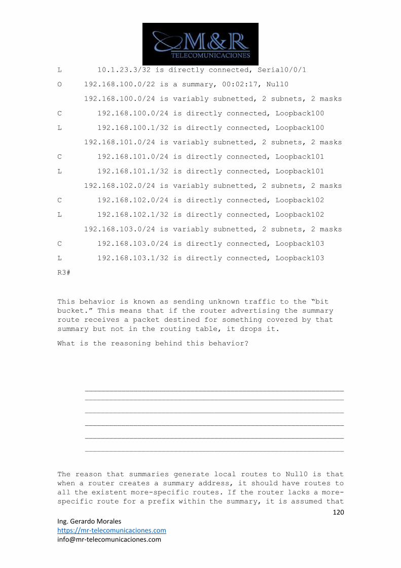
120 Ing. Gerardo Morales https://mr-telecomunicaciones.com [email protected]
L 10.1.23.3/32 is directly connected, Serial0/0/1
O 192.168.100.0/22 is a summary, 00:02:17, Null0
192.168.100.0/24 is variably subnetted, 2 subnets, 2 masks
C 192.168.100.0/24 is directly connected, Loopback100
L 192.168.100.1/32 is directly connected, Loopback100
192.168.101.0/24 is variably subnetted, 2 subnets, 2 masks
C 192.168.101.0/24 is directly connected, Loopback101
L 192.168.101.1/32 is directly connected, Loopback101
192.168.102.0/24 is variably subnetted, 2 subnets, 2 masks
C 192.168.102.0/24 is directly connected, Loopback102
L 192.168.102.1/32 is directly connected, Loopback102
192.168.103.0/24 is variably subnetted, 2 subnets, 2 masks
C 192.168.103.0/24 is directly connected, Loopback103
L 192.168.103.1/32 is directly connected, Loopback103
R3#
This behavior is known as sending unknown traffic to the “bit
bucket.” This means that if the router advertising the summary
route receives a packet destined for something covered by that
summary but not in the routing table, it drops it.
What is the reasoning behind this behavior?
________________________________________________________________
________________________________________________________________
________________________________________________________________
________________________________________________________________
________________________________________________________________
________________________________________________________________
The reason that summaries generate local routes to Null0 is that
when a router creates a summary address, it should have routes to
all the existent more-specific routes. If the router lacks a more-
specific route for a prefix within the summary, it is assumed that
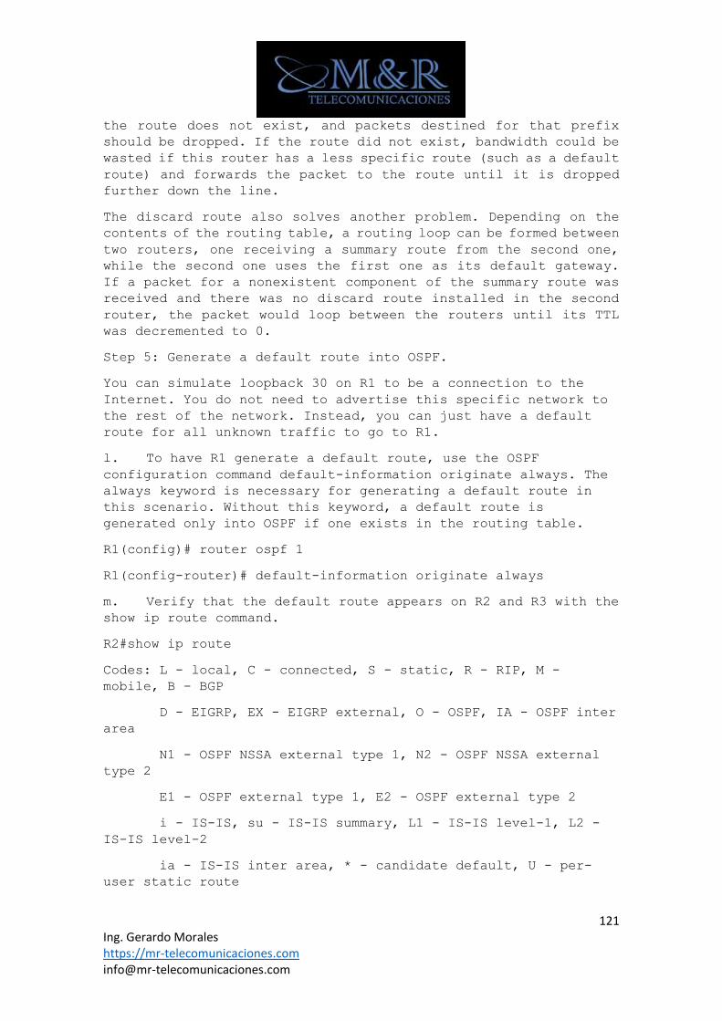
121 Ing. Gerardo Morales https://mr-telecomunicaciones.com [email protected]
the route does not exist, and packets destined for that prefix
should be dropped. If the route did not exist, bandwidth could be
wasted if this router has a less specific route (such as a default
route) and forwards the packet to the route until it is dropped
further down the line.
The discard route also solves another problem. Depending on the
contents of the routing table, a routing loop can be formed between
two routers, one receiving a summary route from the second one,
while the second one uses the first one as its default gateway.
If a packet for a nonexistent component of the summary route was
received and there was no discard route installed in the second
router, the packet would loop between the routers until its TTL
was decremented to 0.
Step 5: Generate a default route into OSPF.
You can simulate loopback 30 on R1 to be a connection to the
Internet. You do not need to advertise this specific network to
the rest of the network. Instead, you can just have a default
route for all unknown traffic to go to R1.
l. To have R1 generate a default route, use the OSPF
configuration command default-information originate always. The
always keyword is necessary for generating a default route in
this scenario. Without this keyword, a default route is
generated only into OSPF if one exists in the routing table.
R1(config)# router ospf 1
R1(config-router)# default-information originate always
m. Verify that the default route appears on R2 and R3 with the
show ip route command.
R2#show ip route
Codes: L - local, C - connected, S - static, R - RIP, M -
mobile, B - BGP
D - EIGRP, EX - EIGRP external, O - OSPF, IA - OSPF inter
area
N1 - OSPF NSSA external type 1, N2 - OSPF NSSA external
type 2
E1 - OSPF external type 1, E2 - OSPF external type 2
i - IS-IS, su - IS-IS summary, L1 - IS-IS level-1, L2 -
IS-IS level-2
ia - IS-IS inter area, * - candidate default, U - per-
user static route
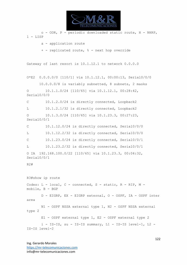
122 Ing. Gerardo Morales https://mr-telecomunicaciones.com [email protected]
o - ODR, P - periodic downloaded static route, H - NHRP,
l - LISP
a - application route
+ - replicated route, % - next hop override
Gateway of last resort is 10.1.12.1 to network 0.0.0.0
O*E2 0.0.0.0/0 [110/1] via 10.1.12.1, 00:00:13, Serial0/0/0
10.0.0.0/8 is variably subnetted, 8 subnets, 2 masks
O 10.1.1.0/24 [110/65] via 10.1.12.1, 00:28:42,
Serial0/0/0
C 10.1.2.0/24 is directly connected, Loopback2
L 10.1.2.1/32 is directly connected, Loopback2
O 10.1.3.0/24 [110/65] via 10.1.23.3, 00:27:23,
Serial0/0/1
C 10.1.12.0/24 is directly connected, Serial0/0/0
L 10.1.12.2/32 is directly connected, Serial0/0/0
C 10.1.23.0/24 is directly connected, Serial0/0/1
L 10.1.23.2/32 is directly connected, Serial0/0/1
O IA 192.168.100.0/22 [110/65] via 10.1.23.3, 00:04:32,
Serial0/0/1
R2#
R3#show ip route
Codes: L - local, C - connected, S - static, R - RIP, M -
mobile, B - BGP
D - EIGRP, EX - EIGRP external, O - OSPF, IA - OSPF inter
area
N1 - OSPF NSSA external type 1, N2 - OSPF NSSA external
type 2
E1 - OSPF external type 1, E2 - OSPF external type 2
i - IS-IS, su - IS-IS summary, L1 - IS-IS level-1, L2 -
IS-IS level-2
123 Ing. Gerardo Morales https://mr-telecomunicaciones.com [email protected]
ia - IS-IS inter area, * - candidate default, U - per-
user static route
o - ODR, P - periodic downloaded static route, H - NHRP,
l - LISP
a - application route
+ - replicated route, % - next hop override
Gateway of last resort is 10.1.23.2 to network 0.0.0.0
O*E2 0.0.0.0/0 [110/1] via 10.1.23.2, 00:00:45, Serial0/0/1
10.0.0.0/8 is variably subnetted, 7 subnets, 2 masks
O 10.1.1.0/24 [110/129] via 10.1.23.2, 00:05:08,
Serial0/0/1
O 10.1.2.0/24 [110/65] via 10.1.23.2, 00:05:08,
Serial0/0/1
C 10.1.3.0/24 is directly connected, Loopback3
L 10.1.3.1/32 is directly connected, Loopback3
O 10.1.12.0/24 [110/128] via 10.1.23.2, 00:05:08,
Serial0/0/1
C 10.1.23.0/24 is directly connected, Serial0/0/1
L 10.1.23.3/32 is directly connected, Serial0/0/1
O 192.168.100.0/22 is a summary, 00:05:08, Null0
192.168.100.0/24 is variably subnetted, 2 subnets, 2 masks
C 192.168.100.0/24 is directly connected, Loopback100
L 192.168.100.1/32 is directly connected, Loopback100
192.168.101.0/24 is variably subnetted, 2 subnets, 2 masks
C 192.168.101.0/24 is directly connected, Loopback101
L 192.168.101.1/32 is directly connected, Loopback101
192.168.102.0/24 is variably subnetted, 2 subnets, 2 masks
C 192.168.102.0/24 is directly connected, Loopback102
L 192.168.102.1/32 is directly connected, Loopback102
192.168.103.0/24 is variably subnetted, 2 subnets, 2 masks
124 Ing. Gerardo Morales https://mr-telecomunicaciones.com [email protected]
C 192.168.103.0/24 is directly connected, Loopback103
L 192.168.103.1/32 is directly connected, Loopback103
R3#
n. You should be able to ping the interface connecting to the
Internet from R2 or R3, despite never being advertised into
OSPF.
R3# ping 172.30.30.1
Type escape sequence to abort.
Sending 5, 100-byte ICMP Echos to 172.30.30.1, timeout is 2
seconds:
!!!!!
Success rate is 100 percent (5/5), round-trip min/avg/max =
28/30/32 ms
Device Configurations (Instructor version)
Initial Configurations
hostname R1
!
interface Loopback1
description Engineering Department
ip address 10.1.1.1 255.255.255.0
!
interface Loopback30
ip address 172.30.30.1 255.255.255.252
!
interface Serial0/0/0
ip address 10.1.12.1 255.255.255.0
clock rate 64000
no shutdown
!
125 Ing. Gerardo Morales https://mr-telecomunicaciones.com [email protected]
end
Router R2
hostname R2
!
interface Loopback2
description Marketing Department
ip address 10.1.2.1 255.255.255.0
!
interface Serial0/0/0
ip address 10.1.12.2 255.255.255.0
no shutdown
!
interface Serial0/0/1
ip address 10.1.23.2 255.255.255.0
clock rate 64000
no shutdown
!
end
Router R3
hostname R3
!
interface Loopback3
description Accounting Department
ip address 10.1.3.1 255.255.255.0
!
interface Loopback100
ip address 192.168.100.1 255.255.255.0
126 Ing. Gerardo Morales https://mr-telecomunicaciones.com [email protected]
!
interface Loopback101
ip address 192.168.101.1 255.255.255.0
!
interface Loopback102
ip address 192.168.102.1 255.255.255.0
!
interface Loopback103
ip address 192.168.103.1 255.255.255.0
!
interface Serial0/0/1
ip address 10.1.23.3 255.255.255.0
no shutdown
!
end
Device Configurations (Instructor version)
Router R1
hostname R1
!
interface Loopback1
description Engineering Department
ip address 10.1.1.1 255.255.255.0
ip ospf network point-to-point
!
interface Loopback30
ip address 172.30.30.1 255.255.255.252
!
interface Serial0/0/0
127 Ing. Gerardo Morales https://mr-telecomunicaciones.com [email protected]
ip address 10.1.12.1 255.255.255.0
clock rate 64000
no shutdown
!
router ospf 1
router-id 1.1.1.1
network 10.1.1.0 0.0.0.255 area 0
network 10.1.12.0 0.0.0.255 area 0
default-information originate always
!
end
Router R2
hostname R2
!
interface Loopback2
description Marketing Department
ip address 10.1.2.1 255.255.255.0
ip ospf network point-to-point
!
interface Serial0/0/0
ip address 10.1.12.2 255.255.255.0
no shutdown
!
interface Serial0/0/1
ip address 10.1.23.2 255.255.255.0
clock rate 64000
no shutdown
!
router ospf 1
128 Ing. Gerardo Morales https://mr-telecomunicaciones.com [email protected]
router-id 2.2.2.2
area 23 virtual-link 3.3.3.3
network 10.1.2.0 0.0.0.255 area 0
network 10.1.12.0 0.0.0.255 area 0
network 10.1.23.0 0.0.0.255 area 23
!
end
Router R3
hostname R3
!
interface Loopback3
description Accounting Department
ip address 10.1.3.1 255.255.255.0
ip ospf network point-to-point
!
interface Loopback100
ip address 192.168.100.1 255.255.255.0
ip ospf network point-to-point
!
interface Loopback101
ip address 192.168.101.1 255.255.255.0
ip ospf network point-to-point
!
interface Loopback102
ip address 192.168.102.1 255.255.255.0
ip ospf network point-to-point
!
interface Loopback103
ip address 192.168.103.1 255.255.255.0
129 Ing. Gerardo Morales https://mr-telecomunicaciones.com [email protected]
ip ospf network point-to-point
!
interface Serial0/0/1
ip address 10.1.23.3 255.255.255.0
no shutdown
!
router ospf 1
router-id 3.3.3.3
area 23 virtual-link 2.2.2.2
area 100 range 192.168.100.0 255.255.252.0
network 10.1.3.0 0.0.0.255 area 23
network 10.1.23.0 0.0.0.255 area 23
network 192.168.100.0 0.0.3.255 area 100
!
end
RADIUS Server
Show Commands
R1# show aaa servers
R1# show radius server-group all
Dialer Interface Router (config-if)#ip address negotiated
Router (config-if)#encapsulation ppp
Router (config-if)#dialer pool number
Configurar Externally Facing Ethernet Interface
Router(config-if)#ppoe-client dial-pool-number number
Router(config-if)#ip nat outside
130 Ing. Gerardo Morales https://mr-telecomunicaciones.com [email protected]
Switching
VLANS
Crear un Vlan
Switch# configure terminal
Switch(config)# vlan 5
Switch(config-vlan)# name Engineering
Switch(config-vlan)# exit
Configuración de un Puerto Troncal
Switch(config)# interface FastEthernet 5/8
Switch(config-if)# switchport trunk encapsulation dot1q -----
Varios switchs ya no necesitan este commando
Switch(config-if)# switchport mode trunk --- Por defecto pasa
todas las VLANs
Switch(config-if)# switchport nonegotiate optional
Switch(config-if)# switchport trunk allowed vlan 1-100
Switch(config-if)# no shutdown
Switch(config-if)# end
Configurando Puertos de Acesso
ALS1(config)# inter fa 0/6
ALS1(config-if)# switchport mode access
131 Ing. Gerardo Morales https://mr-telecomunicaciones.com [email protected]
Configurar VLAN
Switch# configure terminal
Enter configuration commands, one per line. End with CNTL/Z.
Switch(config)# hostname DLS1
DLS1(config)# interface vlan 1
DLS1(config-if)# ip address 10.1.1.101 255.255.255.0
DLS1(config-if)# no shutdown
DLS1(config)# end
Asignando un Puerto a una VLAN
Switch(config)# interface FastEthernet 5/6
Switch(config-if)# description PC A
Switch(config-if)# switchport access vlan 200
Switch(config-if)# no shutdown
Switch(config-if)# end
Borrando VLANs
DLS1(config)# inter fa 0/1
DLS1(config-if)# no switchport access vlan 55
DLS1(config-if)# exit
DLS1(config)# no vlan 55
DLS1(config)# end
Configurando VLAN Nativa
DLS2(config)# interface fa 0/11
DLS2(config-if)# switchport trunk native vlan 2
Configurando Private Vlans
Creando PVlans
Switch(config)# vlan 100
Switch(config-vlan)# private-vlan primary
Switch(config)# vlan 200
Switch(config-vlan)# private-vlan community
Switch(config)# vlan 201
Switch(config-vlan)# private-vlan community
Switch(config)# vlan 300
132 Ing. Gerardo Morales https://mr-telecomunicaciones.com [email protected]
Switch(config-vlan)# private-vlan isolated
Switch(config)# vlan 100
Switch(config-vlan)# private-vlan association 200,201,300
Switch(config)# interface vlan 100
Switch(config-if)# private-vlan mapping add 200,201,300
Configurando Asociaciones de puertos en PVlans
Switch(config)# interface range fa 0/1 – 5
Switch(config-if)# switchport mode private-vlan promiscuous
Switch(config-if)# exit
Switch(config)# interface range fa 0/10 – 12
Switch(config-if)# switchport mode private-vlan host
Switch(config-if)# switchport private-vlan host-association 100
200
Switch(config-if)# exit
Switch(config)# interface range fa 0/15 – 18
Switch(config-if)# switchport mode private-vlan host
Switch(config-if)# switchport private-vlan host-association 100
201
Switch(config-if)# exit
Switch(config)# interface range fa 0/20 – 25
Switch(config-if)# switchport mode private-vlan host
Switch(config-if)# switchport private-vlan host-association 100
300
Switch(config-if)# exit
Troubleshooting
Switch# show vlan id [numero de vlan]
Switch# show running-config interface FastEthernet [interface]
Switch# show interfaces f0/18 switchport
Switch# show mac-address-table interface GigabitEthernet 0/1
vlan 1
ALS1# show interface trunk
Vlan de Voz
Switch(config)# interface type mod/num

133 Ing. Gerardo Morales https://mr-telecomunicaciones.com [email protected]
Switch(config-if)# switchport voice vlan {vlan-id | dot1p |
untagged | none}
Switchport voice vlan none
Switch(config)# interface type mod/num
Switch(config-if)# switchport voice vlan none
Switchport voice vlan dot1p
Switch(config)# interface type mod/num
Switch(config-if)# switchport voice vlan dot1p
Switchport voice vlan untagged
Switch(config)# interface type mod/num
Switch(config-if)# switchport voice vlan untagged
Switchport voice vlan vvid (opción recomendada)
Switch(config)# interface type mod/num
Switch(config-if)# switchport voice vlan vlan-id
VTP
Configurando Dominios
Servidor
DLS1(config)# vtp domain SWLAB
DLS1(config)# vtp password cisco
Cliente
ALS1(config)# vtp domain Cabrillo
ALS1(config)# vtp password cisco
Configurando el servidor y cliente
DLS1(config)# vtp mode server
ALS1(config)# vtp mode client
Configurando VTP Pruning
DLS1(config)# vtp pruning
DLS1(config)# end
EtherChannel
Configurando EtherChannel Load Balancing
Switch(config)# port-channel load-balance src-dst-ip
134 Ing. Gerardo Morales https://mr-telecomunicaciones.com [email protected]
Asignando puertos y configurando el protocolo
DLS1(config)# interface range fa 0/1 - 4
DLS1(config-if-range)# channel-protocol ?
lacp Prepare interface for LACP protocol
pagp Prepare interface for PAgP protocol
DLS1(config-if-range)# channel-protocol pagp
Configurando metodos en Pagp
Desirable - auto
DLS1(config-if-range)# channel-group 1 mode ?
active Enable LACP unconditionally
auto Enable PAgP only if a PAgP device is detected
desirable Enable PAgP unconditionally
on Enable Etherchannel only
passive Enable LACP only if a LACP device is detected
DLS1(config-if-range)# channel-group 1 mode desirable
DLS2(config-if-range)# channel-group 1 mode auto
Configurando LACP
DLS1(config)# interface range fa 0/11 - 12
DLS1(config-if-range)# switchport trunk encapsulation dot1q
DLS1(config-if-range)# switchport mode trunk
DLS1(config-if-range)# channel-protocol lacp
DLS1(config-if-range)# channel-group 1 mode active
DLS1(config-if-range)# lacp port-priority 99
DLS1(config)# interface range fa 0/13 - 14
DLS1(config-if-range)# switchport trunk encapsulation dot1q
DLS1(config-if-range)# switchport mode trunk
DLS1(config-if-range)# channel-protocol lacp
DLS1(config-if-range)# channel-group 1 mode active
DLS2(config)# port-channel load-balance src-dst-ip
135 Ing. Gerardo Morales https://mr-telecomunicaciones.com [email protected]
DLS2(config)# interface range fa 0/11 - 12
DLS2(config-if-range)# switchport trunk encapsulation dot1q
DLS2(config-if-range)# channel-protocol lacp
DLS2(config-if-range)# channel-group 1 mode passive
DLS2(config)# interface range fa 0/13 - 14
DLS2(config-if-range)# switchport trunk encapsulation dot1q
DLS2(config-if-range)# switchport mode trunk
DLS2(config-if-range)# channel-protocol lacp
DLS2(config-if-range)# channel-group 1 mode active
Troubleshooting
DLS1# show etherchannel protocol
DLS1# show etherchannel summary
Spanning tree (STP)
Configurando STP
Switch(config)# spanning-tree vlan vlan-id
Switch(config)# no spanning-tree vlan vlan-id
Configurando un Root Bridge
Switch(config)# spanning-tree vlan 1 priority priority
Este comando configura estáticamente la prioridad (en múltiplos
de 4096). Los valores válidos son de 0 a 61.440, Default is
32768. Los valores más bajos se convierten en root Bridge.
Switch(config)# spanning-tree vlan 1 root secondary
Este comando configura este modificador como la raíz secundaria
en caso de que falle el puente raíz. El comando secundario de la
raíz del árbol de expansión modifica la prioridad de puente de
esta conmutación a 28.672.
Cambiar el Root Bridge
Core(config)# spanning-tree vlan 1-30 root primary
Distribution1(config)# spanning-tree vlan 1-30 root secondary
Configurando PortFast
Access2(config)#interface range fa 0/10 - 24
Access2(config-if-range)#switchport mode access
<Previously configured>
136 Ing. Gerardo Morales https://mr-telecomunicaciones.com [email protected]
Access2(config-if-range)#spanning-tree portfast
O
Access2(config)#spanning-tree portfast default
ADVERTENCIA: PortFast sólo se debe activar en los puertos que
están conectados a un solo host.
Configuración de BPDU GUARD
Distribution1(config)#interface range fa 0/10 - 24
Distribution1(config-if-range)#spanning-tree bpduguard
Configuración de Root Guard
Distribution1(config)#interface fa 0/3
Distribution1(config-if-range)#spanning-tree guard root
Distribution1(config)#interface gig 0/2
Distribution1(config-if-range)#spanning-tree guard root
Distribution2(config)#interface fa 0/3
Distribution2(config-if-range)#spanning-tree guard root
Distribution2(config)#interface gig 0/1
Distribution2(config-if-range)#spanning-tree guard root
Access2(config)#no spanning-tree uplinkfast
Implementar PVST
Switch(config)# spanning-tree mode pvst
Implementar PVST+
Switch(config)# spanning-tree mode rapid-pvst
Switch(config-if)# spanning-tree portfast
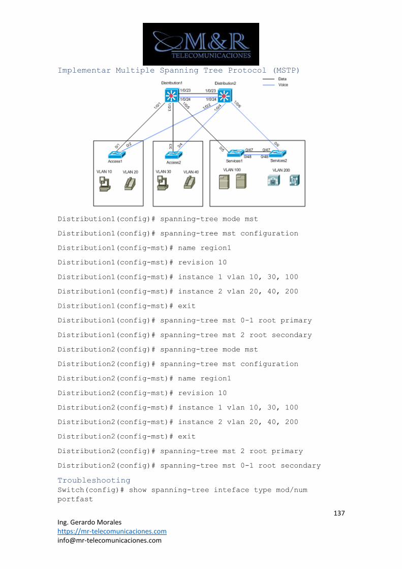
137 Ing. Gerardo Morales https://mr-telecomunicaciones.com [email protected]
Implementar Multiple Spanning Tree Protocol (MSTP)
Distribution1(config)# spanning-tree mode mst
Distribution1(config)# spanning-tree mst configuration
Distribution1(config-mst)# name region1
Distribution1(config-mst)# revision 10
Distribution1(config-mst)# instance 1 vlan 10, 30, 100
Distribution1(config-mst)# instance 2 vlan 20, 40, 200
Distribution1(config-mst)# exit
Distribution1(config)# spanning-tree mst 0-1 root primary
Distribution1(config)# spanning-tree mst 2 root secondary
Distribution2(config)# spanning-tree mode mst
Distribution2(config)# spanning-tree mst configuration
Distribution2(config-mst)# name region1
Distribution2(config-mst)# revision 10
Distribution2(config-mst)# instance 1 vlan 10, 30, 100
Distribution2(config-mst)# instance 2 vlan 20, 40, 200
Distribution2(config-mst)# exit
Distribution2(config)# spanning-tree mst 2 root primary
Distribution2(config)# spanning-tree mst 0-1 root secondary
Troubleshooting
Switch(config)# show spanning-tree inteface type mod/num
portfast
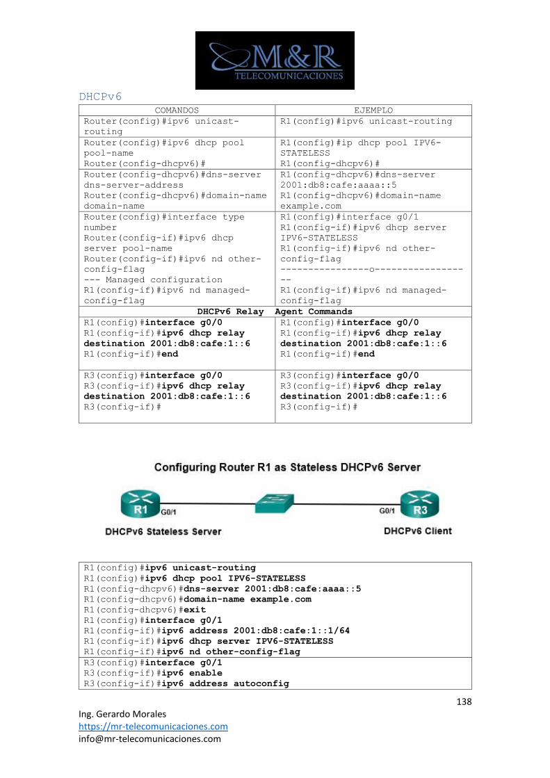
138 Ing. Gerardo Morales https://mr-telecomunicaciones.com [email protected]
DHCPv6
COMANDOS EJEMPLO
Router(config)#ipv6 unicast-
routing
R1(config)#ipv6 unicast-routing
Router(config)#ipv6 dhcp pool
pool-name
Router(config-dhcpv6)#
R1(config)#ip dhcp pool IPV6-
STATELESS
R1(config-dhcpv6)#
Router(config-dhcpv6)#dns-server
dns-server-address
Router(config-dhcpv6)#domain-name
domain-name
R1(config-dhcpv6)#dns-server
2001:db8:cafe:aaaa::5
R1(config-dhcpv6)#domain-name
example.com
Router(config)#interface type
number
Router(config-if)#ipv6 dhcp
server pool-name
Router(config-if)#ipv6 nd other-
config-flag
--- Managed configuration
R1(config-if)#ipv6 nd managed-
config-flag
R1(config)#interface g0/1
R1(config-if)#ipv6 dhcp server
IPV6-STATELESS
R1(config-if)#ipv6 nd other-
config-flag
----------------o----------------
--
R1(config-if)#ipv6 nd managed-
config-flag
DHCPv6 Relay Agent Commands
R1(config)#interface g0/0
R1(config-if)#ipv6 dhcp relay
destination 2001:db8:cafe:1::6
R1(config-if)#end
R1(config)#interface g0/0
R1(config-if)#ipv6 dhcp relay
destination 2001:db8:cafe:1::6
R1(config-if)#end
R3(config)#interface g0/0
R3(config-if)#ipv6 dhcp relay
destination 2001:db8:cafe:1::6
R3(config-if)#
R3(config)#interface g0/0
R3(config-if)#ipv6 dhcp relay
destination 2001:db8:cafe:1::6
R3(config-if)#
R1(config)#ipv6 unicast-routing
R1(config)#ipv6 dhcp pool IPV6-STATELESS
R1(config-dhcpv6)#dns-server 2001:db8:cafe:aaaa::5
R1(config-dhcpv6)#domain-name example.com
R1(config-dhcpv6)#exit
R1(config)#interface g0/1
R1(config-if)#ipv6 address 2001:db8:cafe:1::1/64
R1(config-if)#ipv6 dhcp server IPV6-STATELESS
R1(config-if)#ipv6 nd other-config-flag
R3(config)#interface g0/1
R3(config-if)#ipv6 enable
R3(config-if)#ipv6 address autoconfig
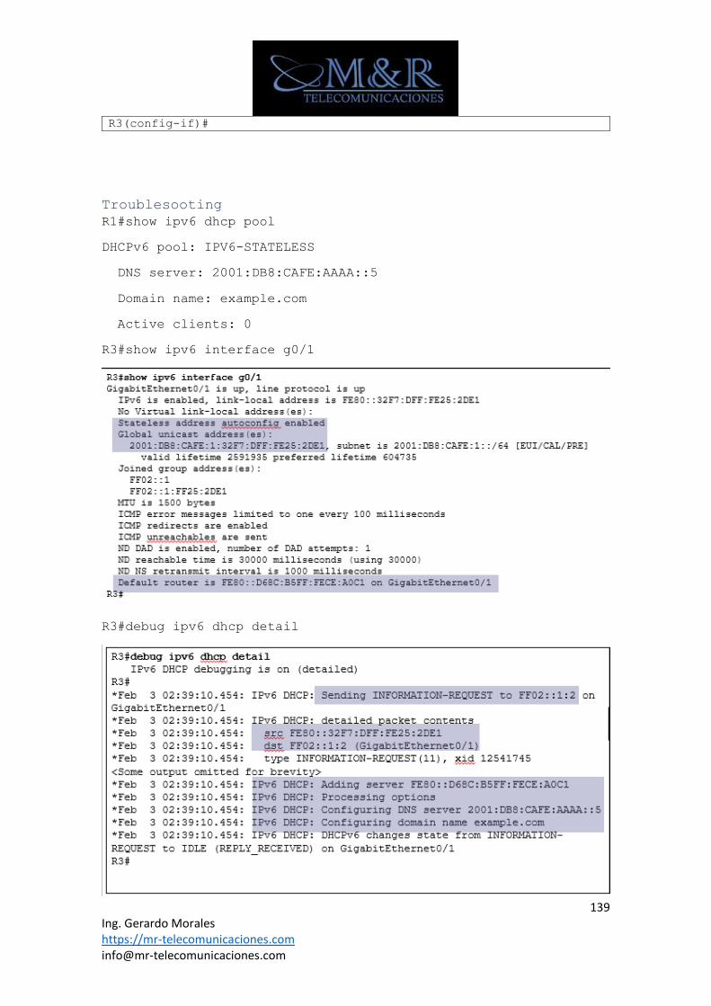
139 Ing. Gerardo Morales https://mr-telecomunicaciones.com [email protected]
R3(config-if)#
Troublesooting
R1#show ipv6 dhcp pool
DHCPv6 pool: IPV6-STATELESS
DNS server: 2001:DB8:CAFE:AAAA::5
Domain name: example.com
Active clients: 0
R3#show ipv6 interface g0/1
R3#debug ipv6 dhcp detail
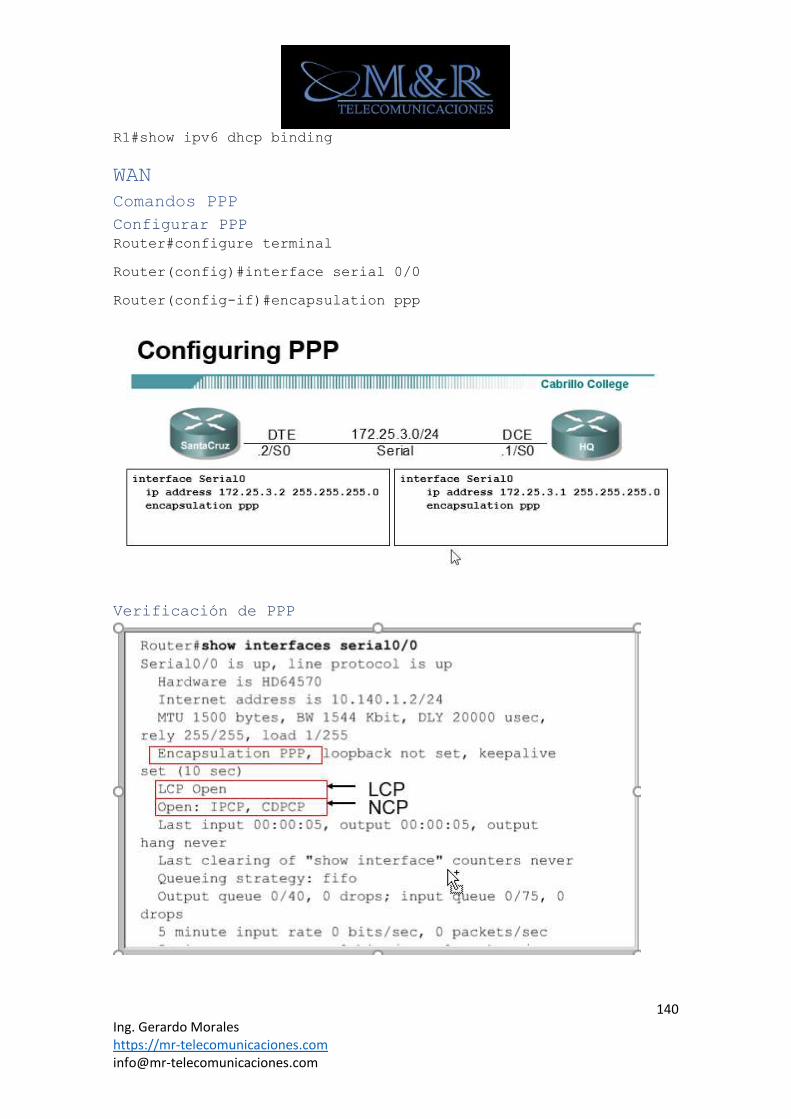
140 Ing. Gerardo Morales https://mr-telecomunicaciones.com [email protected]
R1#show ipv6 dhcp binding
WAN
Comandos PPP
Configurar PPP
Router#configure terminal
Router(config)#interface serial 0/0
Router(config-if)#encapsulation ppp
Verificación de PPP
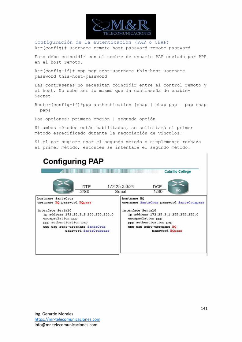
141 Ing. Gerardo Morales https://mr-telecomunicaciones.com [email protected]
Configuración de la autenticación (PAP o CHAP)
Rtr(config)# username remote-host password remote-password
Esto debe coincidir con el nombre de usuario PAP enviado por PPP
en el host remoto.
Rtr(config-if)# ppp pap sent-username this-host username
password this-host-password
Las contraseñas no necesitan coincidir entre el control remoto y
el host. No debe ser lo mismo que la contraseña de enable-
Secret.
Router(config-if)#ppp authentication {chap | chap pap | pap chap
| pap}
Dos opciones: primera opción | segunda opción
Si ambos métodos están habilitados, se solicitará el primer
método especificado durante la negociación de vínculos.
Si el par sugiere usar el segundo método o simplemente rechaza
el primer método, entonces se intentará el segundo método.
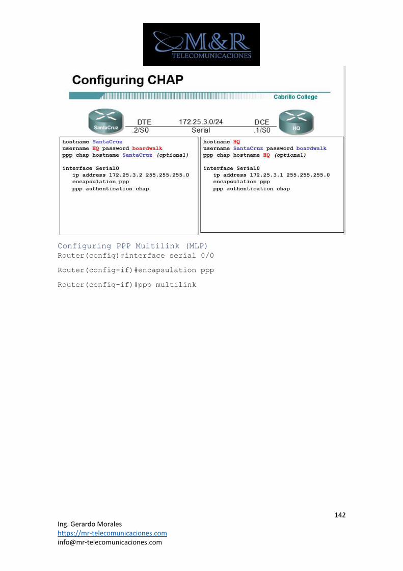
142 Ing. Gerardo Morales https://mr-telecomunicaciones.com [email protected]
Configuring PPP Multilink (MLP)
Router(config)#interface serial 0/0
Router(config-if)#encapsulation ppp
Router(config-if)#ppp multilink
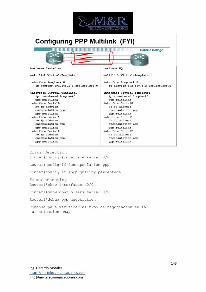
143 Ing. Gerardo Morales https://mr-telecomunicaciones.com [email protected]
Error Detection
Router(config)#interface serial 0/0
Router(config-if)#encapsulation ppp
Router(config-if)#ppp quality percentage
Troubleshooting
Router1#show interfaces s0/0
Router1#show controllers serial 0/0
Router1#debug ppp negotiation
Comando para verificar el tipo de negociacion en la
autenticacion chap
145 Ing. Gerardo Morales https://mr-telecomunicaciones.com [email protected]
Configuración de EBGP
Router(config)#router bgp AS-number
RTA(config)#router bgp 100
Router(config-router)#neighbor ip-address remote-as AS-number
RTA(config-router)#neighbor 10.1.1.1 remote-as 200
RTA(config)#router bgp 100
Router(config-router)#network 192.0.2.0 mask 255.255.255.0
Configurar rutas de descarte
Ip route 192.0.2.0 255.255.255.0 null0
Show Commands
R1# show ip interface brief
R1# show ip bgp
R1# show ip bgp neighbors
R1# show ip bgp summary
R1# show tcp brief
Primero, el comando show tcp brief muestra todas las conexiones
TCP que termnan en este enrutador (RI ya sea BGP o no. Cada
linea enumera la dirección IP del enrutador local)
R1# show ip route [network mask] longer-prefixes
R1# show ip route 192.0.2.0 255.255.255.0 longer-prefixes
Directamente el proceso BGP añadira a la entrada BGP con
prefijo/mascara si el prefijo/mascara existe en la table IP
Estado vecino con el Neighbor Shut Down
R1# configure terminal
Enter configuration commands, one per line. End with CNTL/Z.
R1(config)# router bgp 1001
R1(config-router)# neighbor 198.51.100.2 shutdown
Alta disponibilidad
HSRP
Configuración HSRP Switchs
Switch(config-if)#standby group-number ip virtual-ip-address
Switch(config-if)#standby version 2 ------se configura la
versión 2 HSRP por defecto viene la versión 1----
146 Ing. Gerardo Morales https://mr-telecomunicaciones.com [email protected]
Switch(config-if)#standby group-number priority priority-value
El valor de prioridad indica el número que prioriza un enrutador
de reserva potencial. La gama es 0 a 255; el valor por defecto
es 100
Switch(config-if)#standby group-number preempt [delay [minimum
seconds] [reload seconds]]
Minimo: 0-3600
Reload: 0-3600
Para habilitar un enrutador para reanudar el estado activo
después de un cambio de estado, introduzca el siguiente comando
en el modo de configuración de interfaz
Switch(config-ig)# standby group timers [msec] hellotime [msec]
holdtime
Autenticación texto plano
Switch(config-if)# standby group-number authentication string
Switch(config-if)# standby 1 authentication password
Autenticación MD5
Switch(config-if)#standby group-number authentication md5 key-
string [0|7] string
Switch(config-if)#standby 1 authentication md5 key-string
password
Configurando HSRP Interface Tracking
Hellotime
Default = 3 seconds
Value varies from 1 to 255.
Holdtime
Default = 10 seconds
Value varies from 1 to 255
group-number: se refiere al número de grupo de espera HSRP, el
número de grupo puede variar entre 0 y 255.
virtual-ip-address: indica la dirección IP virtual del grupo
HSRP
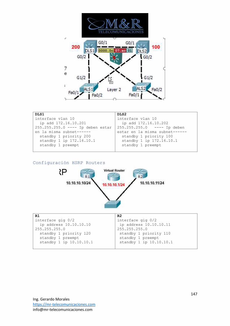
147 Ing. Gerardo Morales https://mr-telecomunicaciones.com [email protected]
DLS1
interface vlan 10
ip add 172.16.10.201
255.255.255.0 ---- Ip deben estar
en la misma subnet------
standby 1 priority 200
standby 1 ip 172.16.10.1
standby 1 preempt
DLS2
interface vlan 10
ip add 172.16.10.202
255.255.255.0 ---- Ip deben
estar en la misma subnet------
standby 1 priority 100
standby 1 ip 172.16.10.1
standby 1 preempt
Configuración HSRP Routers
R1
interface gig 0/2
ip address 10.10.10.10
255.255.255.0
standby 1 priority 120
standby 1 preempt
standby 1 ip 10.10.10.1
R2
interface gig 0/2
ip address 10.10.10.11
255.255.255.0
standby 1 priority 110
standby 1 preempt
standby 1 ip 10.10.10.1
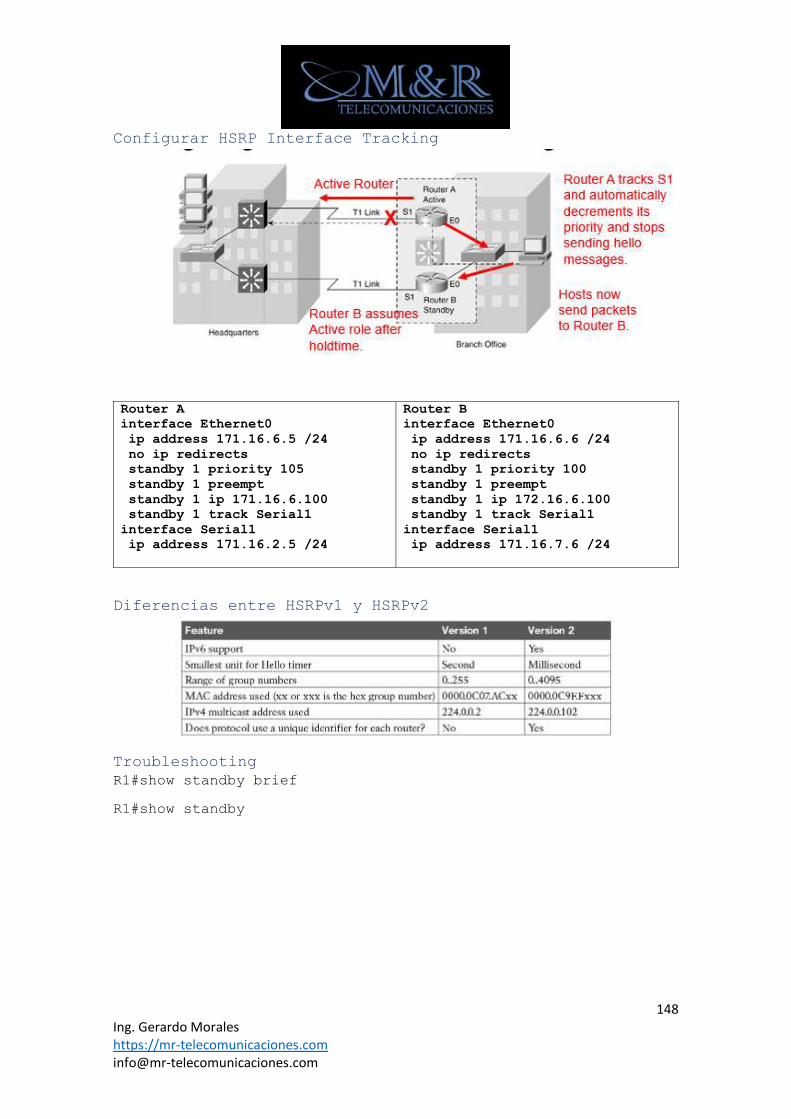
148 Ing. Gerardo Morales https://mr-telecomunicaciones.com [email protected]
Configurar HSRP Interface Tracking
Router A
interface Ethernet0
ip address 171.16.6.5 /24
no ip redirects
standby 1 priority 105
standby 1 preempt
standby 1 ip 171.16.6.100
standby 1 track Serial1
interface Serial1
ip address 171.16.2.5 /24
Router B
interface Ethernet0
ip address 171.16.6.6 /24
no ip redirects
standby 1 priority 100
standby 1 preempt
standby 1 ip 172.16.6.100
standby 1 track Serial1
interface Serial1
ip address 171.16.7.6 /24
Diferencias entre HSRPv1 y HSRPv2
Troubleshooting
R1#show standby brief
R1#show standby
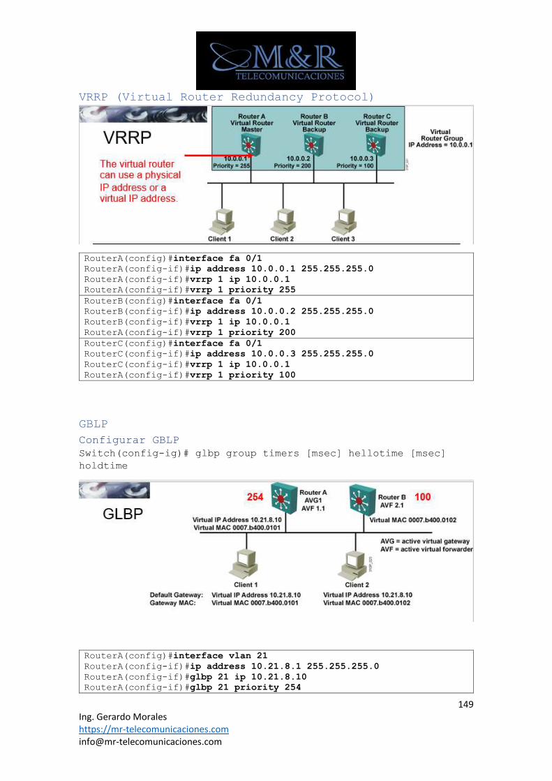
149 Ing. Gerardo Morales https://mr-telecomunicaciones.com [email protected]
VRRP (Virtual Router Redundancy Protocol)
RouterA(config)#interface fa 0/1
RouterA(config-if)#ip address 10.0.0.1 255.255.255.0
RouterA(config-if)#vrrp 1 ip 10.0.0.1
RouterA(config-if)#vrrp 1 priority 255
RouterB(config)#interface fa 0/1
RouterB(config-if)#ip address 10.0.0.2 255.255.255.0
RouterB(config-if)#vrrp 1 ip 10.0.0.1
RouterA(config-if)#vrrp 1 priority 200
RouterC(config)#interface fa 0/1
RouterC(config-if)#ip address 10.0.0.3 255.255.255.0
RouterC(config-if)#vrrp 1 ip 10.0.0.1
RouterA(config-if)#vrrp 1 priority 100
GBLP
Configurar GBLP
Switch(config-ig)# glbp group timers [msec] hellotime [msec]
holdtime
RouterA(config)#interface vlan 21
RouterA(config-if)#ip address 10.21.8.1 255.255.255.0
RouterA(config-if)#glbp 21 ip 10.21.8.10
RouterA(config-if)#glbp 21 priority 254
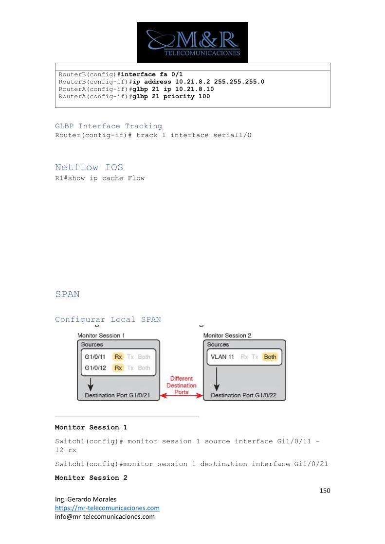
150 Ing. Gerardo Morales https://mr-telecomunicaciones.com [email protected]
RouterB(config)#interface fa 0/1
RouterB(config-if)#ip address 10.21.8.2 255.255.255.0
RouterA(config-if)#glbp 21 ip 10.21.8.10
RouterA(config-if)#glbp 21 priority 100
GLBP Interface Tracking
Router(config-if)# track 1 interface serial1/0
Netflow IOS R1#show ip cache Flow
SPAN
Configurar Local SPAN
Monitor Session 1
Switch1(config)# monitor session 1 source interface Gi1/0/11 -
12 rx
Switch1(config)#monitor session 1 destination interface Gi1/0/21
Monitor Session 2
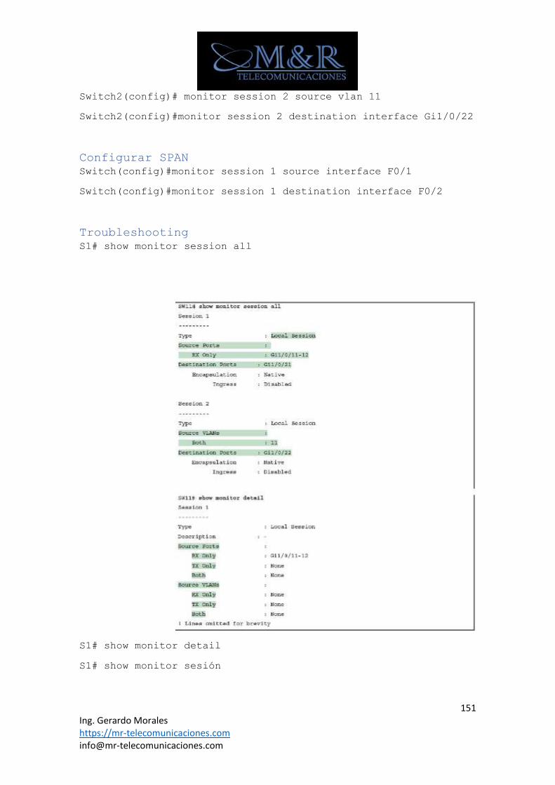
151 Ing. Gerardo Morales https://mr-telecomunicaciones.com [email protected]
Switch2(config)# monitor session 2 source vlan 11
Switch2(config)#monitor session 2 destination interface Gi1/0/22
Configurar SPAN
Switch(config)#monitor session 1 source interface F0/1
Switch(config)#monitor session 1 destination interface F0/2
Troubleshooting
S1# show monitor session all
S1# show monitor detail
S1# show monitor sesión
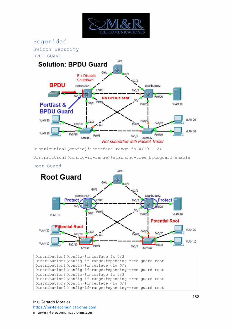
152 Ing. Gerardo Morales https://mr-telecomunicaciones.com [email protected]
Seguridad
Switch Security
BPDU GUARD
Distribution1(config)#interface range fa 0/10 - 24
Distribution1(config-if-range)#spanning-tree bpduguard enable
Root Guard
Distribution1(config)#interface fa 0/3
Distribution1(config-if-range)#spanning-tree guard root
Distribution1(config)#interface gig 0/2
Distribution1(config-if-range)#spanning-tree guard root
Distribution2(config)#interface fa 0/3
Distribution2(config-if-range)#spanning-tree guard root
Distribution2(config)#interface gig 0/1
Distribution2(config-if-range)#spanning-tree guard root
153 Ing. Gerardo Morales https://mr-telecomunicaciones.com [email protected]
Access2(config)#no spanning-tree uplinkfast
Port Security
S1(config)#interface FastEthernet0/2
S1(config-if)# switchport port-security
S1(config-if)# switchport port-security maximum 6
S1(config-if)# switchport port-security aging time 5
S1(config-if)# switchport port-security mac-address
0000.0000.000b
S1(config-if)# switchport port-security mac-address sticky
Opcional habilita aprendizaje stick sobre la interfaz
S1(config-if)# switchport port-security violation shutdown
Switch(config-if)# switchport port-security [maximum value]
violation {protect | restrict | shutdown} mac-address mac-
address
Troubleshooting Port security
Switch#show port-security
Switch# show port-security interface type mod/port
Switch#show port-security address
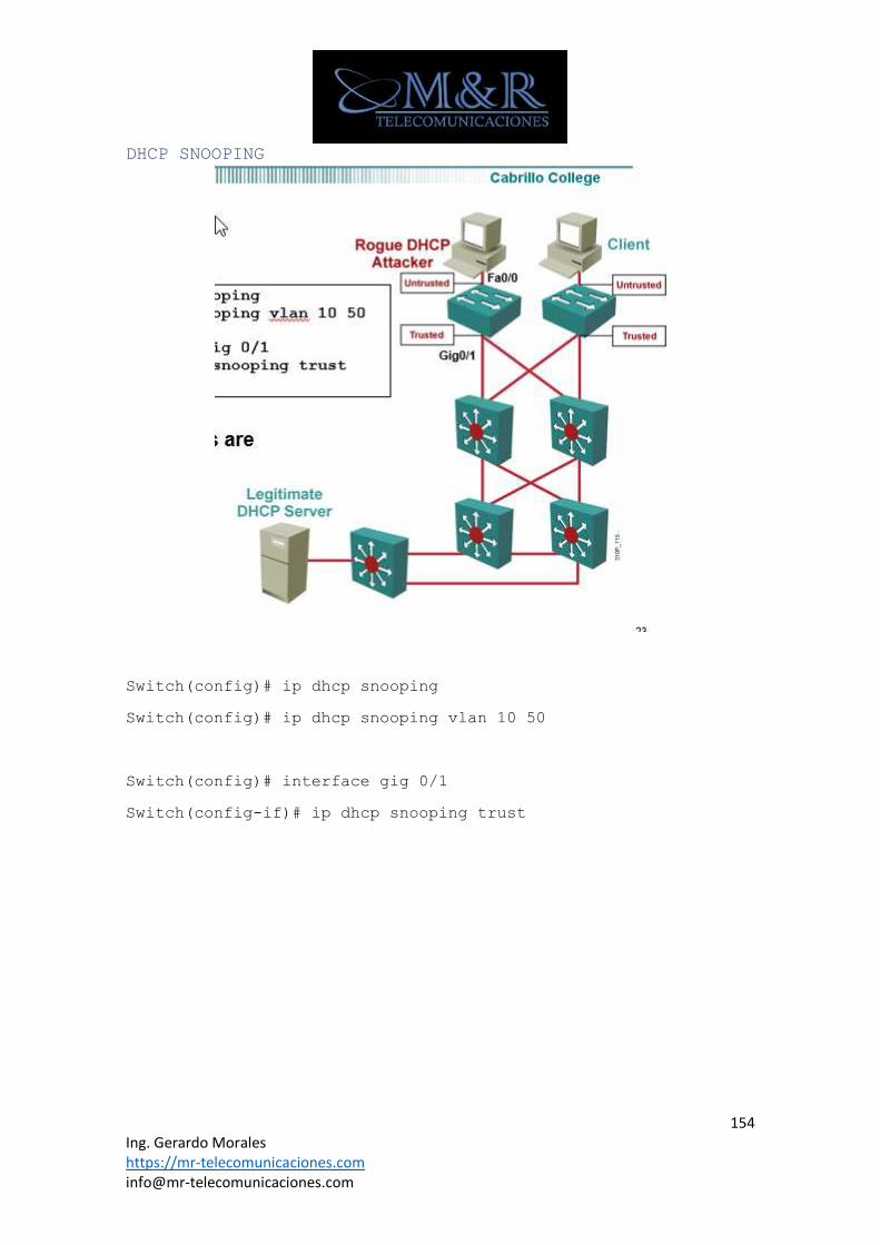
154 Ing. Gerardo Morales https://mr-telecomunicaciones.com [email protected]
DHCP SNOOPING
Switch(config)# ip dhcp snooping
Switch(config)# ip dhcp snooping vlan 10 50
Switch(config)# interface gig 0/1
Switch(config-if)# ip dhcp snooping trust
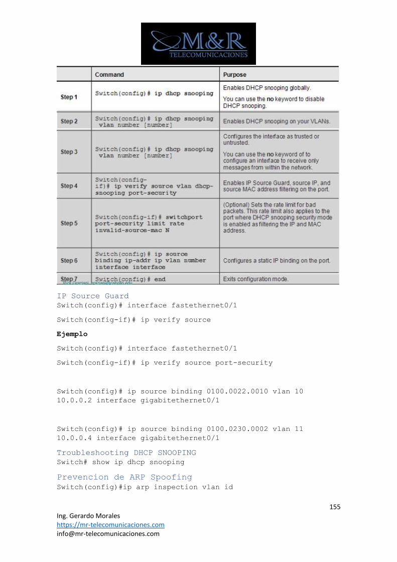
155 Ing. Gerardo Morales https://mr-telecomunicaciones.com [email protected]
IP Source Guard
Switch(config)# interface fastethernet0/1
Switch(config-if)# ip verify source
Ejemplo
Switch(config)# interface fastethernet0/1
Switch(config-if)# ip verify source port-security
Switch(config)# ip source binding 0100.0022.0010 vlan 10
10.0.0.2 interface gigabitethernet0/1
Switch(config)# ip source binding 0100.0230.0002 vlan 11
10.0.0.4 interface gigabitethernet0/1
Troubleshooting DHCP SNOOPING
Switch# show ip dhcp snooping
Prevencion de ARP Spoofing
Switch(config)#ip arp inspection vlan id
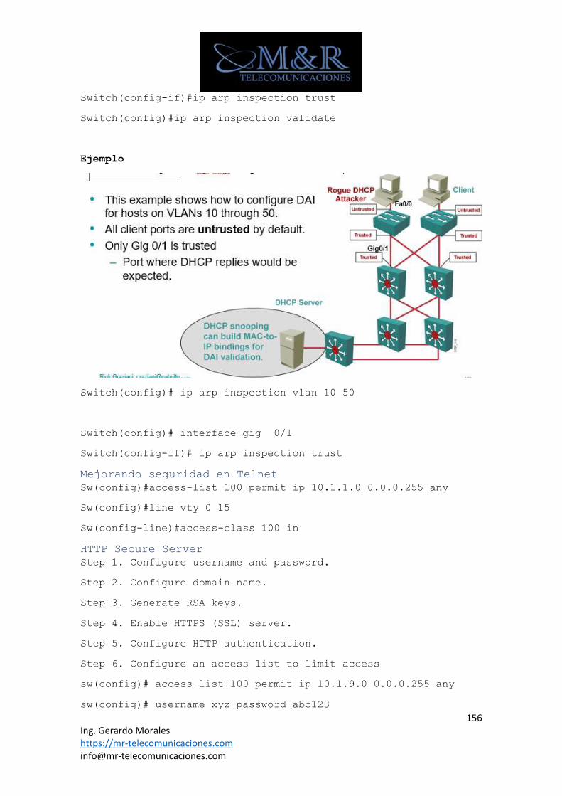
156 Ing. Gerardo Morales https://mr-telecomunicaciones.com [email protected]
Switch(config-if)#ip arp inspection trust
Switch(config)#ip arp inspection validate
Ejemplo
Switch(config)# ip arp inspection vlan 10 50
Switch(config)# interface gig 0/1
Switch(config-if)# ip arp inspection trust
Mejorando seguridad en Telnet
Sw(config)#access-list 100 permit ip 10.1.1.0 0.0.0.255 any
Sw(config)#line vty 0 15
Sw(config-line)#access-class 100 in
HTTP Secure Server
Step 1. Configure username and password.
Step 2. Configure domain name.
Step 3. Generate RSA keys.
Step 4. Enable HTTPS (SSL) server.
Step 5. Configure HTTP authentication.
Step 6. Configure an access list to limit access
sw(config)# access-list 100 permit ip 10.1.9.0 0.0.0.255 any
sw(config)# username xyz password abc123
157 Ing. Gerardo Morales https://mr-telecomunicaciones.com [email protected]
sw(config)# ip domain-name xyz.com
sw(config)# crypto key generate rsa
sw(config)# no ip http server
sw(config)# ip http secure-server
sw(config)# http access-class 100 in
sw(config)# http authentication local
Authentication, Authorization, and Accounting (AAA)
Switch(config)# aaa new-model
Switch(config)# aaa authentication login TEST tacacs+
Switch(config)# tacacs-server host 192.168.100.100
Switch(config)# line vty 0 4
Switch(config-line)# login authentication TEST
TACACS+
RTA(config)#tacacs-server host 192.168.0.11
RTA(config)#tacacs-server host 192.168.0.12
RTA(config)#tacacs-server key topsecret
RTA(config)# aaa new-model
RTA(config)#aaa authentication enable default group tacacs+
enable none
Radius
RTB(config)#radius-server host 192.168.0.22
RTB(config)#radius-server host 192.168.0.23
RTB(config)#radius-server key topsecret
RTB(config)# aaa new-model
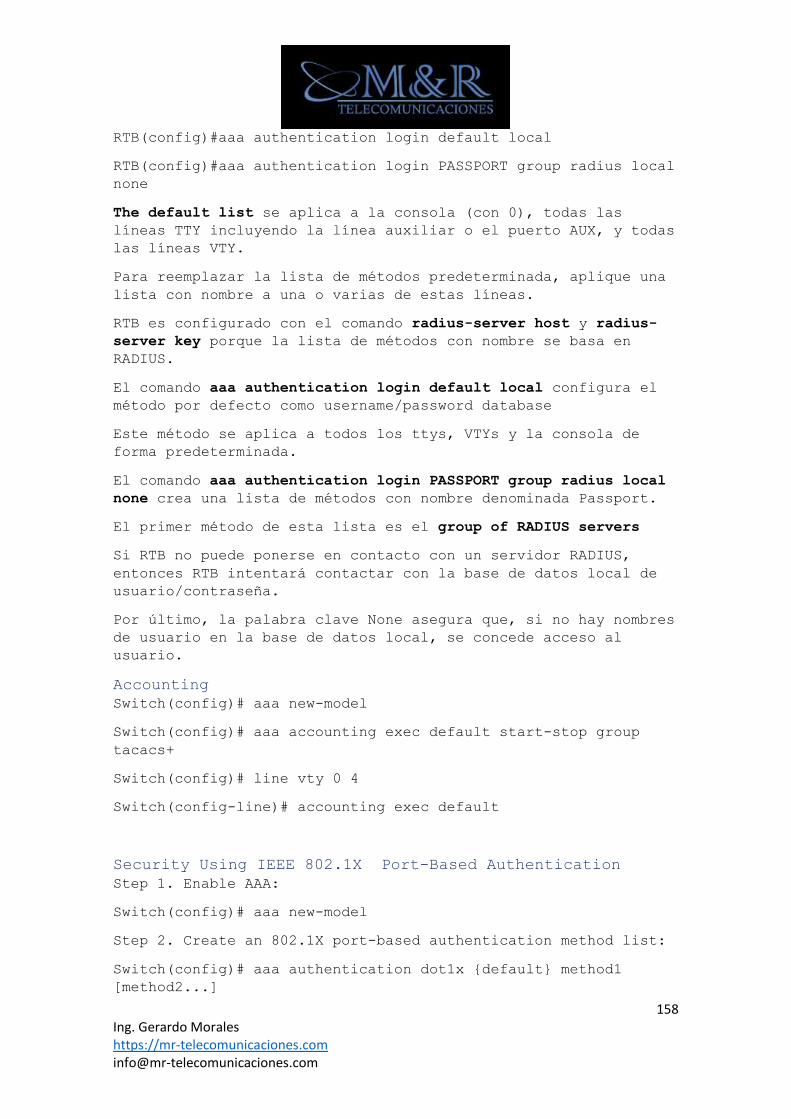
158 Ing. Gerardo Morales https://mr-telecomunicaciones.com [email protected]
RTB(config)#aaa authentication login default local
RTB(config)#aaa authentication login PASSPORT group radius local
none
The default list se aplica a la consola (con 0), todas las
líneas TTY incluyendo la línea auxiliar o el puerto AUX, y todas
las líneas VTY.
Para reemplazar la lista de métodos predeterminada, aplique una
lista con nombre a una o varias de estas líneas.
RTB es configurado con el comando radius-server host y radius-
server key porque la lista de métodos con nombre se basa en
RADIUS.
El comando aaa authentication login default local configura el
método por defecto como username/password database
Este método se aplica a todos los ttys, VTYs y la consola de
forma predeterminada.
El comando aaa authentication login PASSPORT group radius local
none crea una lista de métodos con nombre denominada Passport.
El primer método de esta lista es el group of RADIUS servers
Si RTB no puede ponerse en contacto con un servidor RADIUS,
entonces RTB intentará contactar con la base de datos local de
usuario/contraseña.
Por último, la palabra clave None asegura que, si no hay nombres
de usuario en la base de datos local, se concede acceso al
usuario.
Accounting
Switch(config)# aaa new-model
Switch(config)# aaa accounting exec default start-stop group
tacacs+
Switch(config)# line vty 0 4
Switch(config-line)# accounting exec default
Security Using IEEE 802.1X Port-Based Authentication
Step 1. Enable AAA:
Switch(config)# aaa new-model
Step 2. Create an 802.1X port-based authentication method list:
Switch(config)# aaa authentication dot1x {default} method1
[method2...]
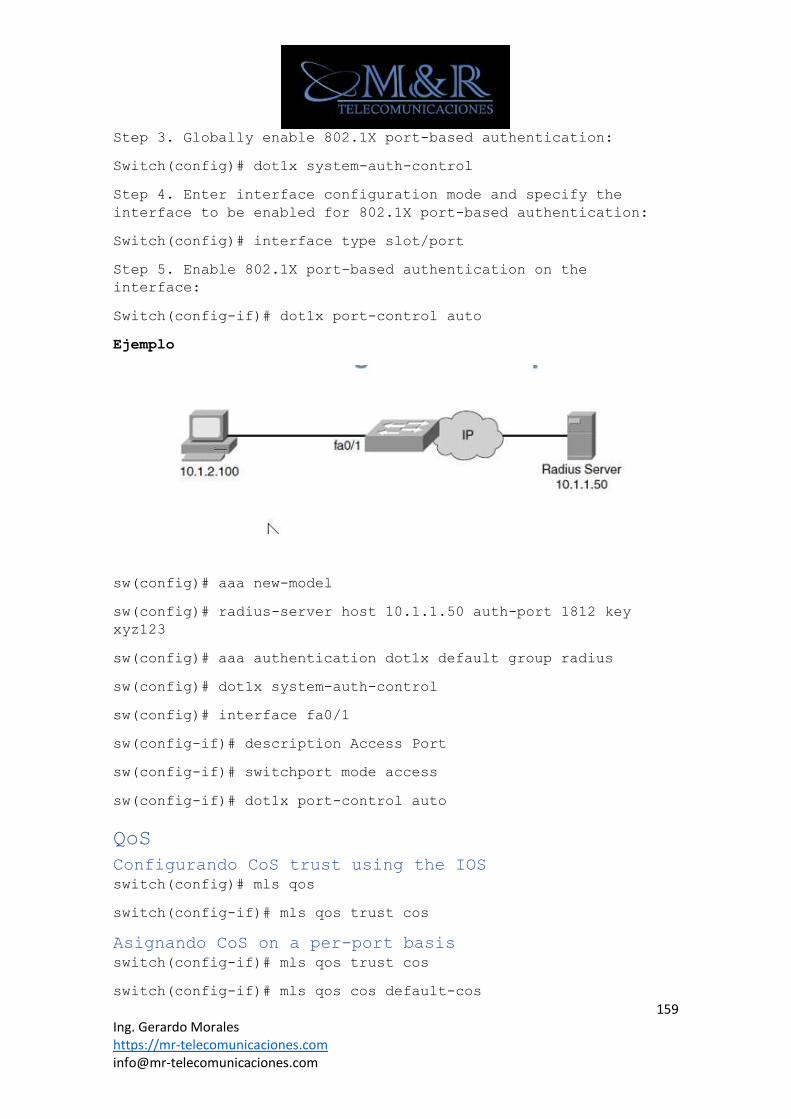
159 Ing. Gerardo Morales https://mr-telecomunicaciones.com [email protected]
Step 3. Globally enable 802.1X port-based authentication:
Switch(config)# dot1x system-auth-control
Step 4. Enter interface configuration mode and specify the
interface to be enabled for 802.1X port-based authentication:
Switch(config)# interface type slot/port
Step 5. Enable 802.1X port-based authentication on the
interface:
Switch(config-if)# dot1x port-control auto
Ejemplo
sw(config)# aaa new-model
sw(config)# radius-server host 10.1.1.50 auth-port 1812 key
xyz123
sw(config)# aaa authentication dot1x default group radius
sw(config)# dot1x system-auth-control
sw(config)# interface fa0/1
sw(config-if)# description Access Port
sw(config-if)# switchport mode access
sw(config-if)# dot1x port-control auto
QoS
Configurando CoS trust using the IOS
switch(config)# mls qos
switch(config-if)# mls qos trust cos
Asignando CoS on a per-port basis
switch(config-if)# mls qos trust cos
switch(config-if)# mls qos cos default-cos
160 Ing. Gerardo Morales https://mr-telecomunicaciones.com [email protected]
Reescribiendo el CoS
Switch(config-if)# mls qos cos override
switch(config-if)# mls qos cos default-cos
Implementing QoS for Voice
1 Habilitar QoS en el switch
Switch(config)# mls qos
2 Defina el parámetro QoS a ser de confianza
Switch(config)# interface type mod/num
Switch(config-if)# mls qos trust {cos | ip-precedence | dscp}
3 Hacer que la confianza condicional sólo si un teléfono IP
de Cisco está presente
Switch(config-if)# mls qos trust device cisco-phone
4 (opcional) instruya al teléfono IP para extender su límite
de confianza al puerto de datos del PC
Switch(config-if)# switchport priority extend {cos value |
trust}
Configuración de QoS para voz
Switch(config-if)# mls qos trust cos
Ejemplo
Switch(config)# interface FastEthernet0/24
Switch(config-if)# switchport access vlan 100
Switch(config-if)# switchport voice vlan 200
Switch(config-if)# mls qos trust cos
Switch(config-if)# mls qos trust cisco-phone
Switch(config-if)# switchport priority extend trust
Auto QoS
Switch(config)# interface type mod/num
Switch(config-if)# auto qos voip {cisco-phone | cisco-softphone
| trust}
Interfaz de línea de comandos de QoS modular (CLI)
Classification of traffic – The class-map
Switch(config)# class-map cisco

161 Ing. Gerardo Morales https://mr-telecomunicaciones.com [email protected]
Switch(config-cmap)# match access-group name test
Switch(config-cmap)# match interface fastethernet 0/1
Definiendo the QoS policy – The policy-map
Switch(config)# policy-map policy1
Switch(config-pmap)# class cisco
Switch(config-pmap-c)# bandwidth 3000
Switch(config-pmap)# class class-default
Switch(config-pmap-c)# bandwidth 2000
Aplicando the policy to an interface – The service-policy
Switch(config)# interface fastethernet 0/1
Switch(config-if)# service-policy output policy1
Switch(config-if)#exit
IP Precedence and DSCP
Configuración de la confianza cos mediante el iOS
switch(config)# mls qos
El fideicomiso se configura en el puerto del switch usando el
comando:
switch(config-if)# mls qos trust cos
162 Ing. Gerardo Morales https://mr-telecomunicaciones.com [email protected]
switch(config-if)# mls qos cos default-cos
Asignando CoS on a per-port basis
switch(config-if)# mls qos trust cos
switch(config-if)# mls qos cos default-cos
Rescribiendo the CoS
Switch(config-if)# mls qos cos override
switch(config-if)# mls qos cos default-cos
Usando a MAC ACL to assign a DSCP value
Switch(config)# mac access-list extended name
Configurando DSCP usando a MAC ACL
Identificar los flujos de tráfico o tráfico
Switch(config)# class-map match-all ipphone
Switch(config-cmap)# match access-group name receptionphone
Cree los criterios de condición.
Switch(config)# mac access-list extended receptionphone
Switch(config-ext-macl)# permit host 000.0a00.0111 any
Verificando
Switch# show class-map
Class Map match-any class-default (id 0)
Match any
Class Map match-all ipphone (id 2)
Match access-group name receptionphone
Identificar las características de QoS de una directiva
Switch(config)# policy-map inbound-accesslayer
Switch(config-pmap)# class ipphone
Switch(config-pmap-c)# set ip dscp 40
Adjunte la Directiva de tráfico a una interfaz.
Switch(config)# interface range fastethernet 0/1 - 24
Switch(config-if-range)# service-policy input inbound-
accesslayer
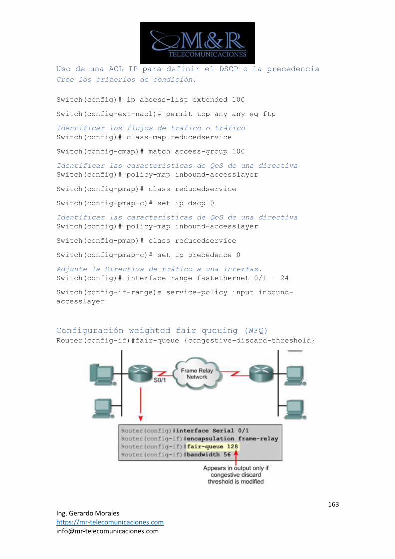
163 Ing. Gerardo Morales https://mr-telecomunicaciones.com [email protected]
Uso de una ACL IP para definir el DSCP o la precedencia
Cree los criterios de condición.
Switch(config)# ip access-list extended 100
Switch(config-ext-nacl)# permit tcp any any eq ftp
Identificar los flujos de tráfico o tráfico
Switch(config)# class-map reducedservice
Switch(config-cmap)# match access-group 100
Identificar las características de QoS de una directiva
Switch(config)# policy-map inbound-accesslayer
Switch(config-pmap)# class reducedservice
Switch(config-pmap-c)# set ip dscp 0
Identificar las características de QoS de una directiva
Switch(config)# policy-map inbound-accesslayer
Switch(config-pmap)# class reducedservice
Switch(config-pmap-c)# set ip precedence 0
Adjunte la Directiva de tráfico a una interfaz.
Switch(config)# interface range fastethernet 0/1 - 24
Switch(config-if-range)# service-policy input inbound-
accesslayer
Configuración weighted fair queuing (WFQ)
Router(config-if)#fair-queue {congestive-discard-threshold}
164 Ing. Gerardo Morales https://mr-telecomunicaciones.com [email protected]
Configuración Class-Based Weighted Fair Queuing
Router(config)# policy-map policy1
Router(config-pmap)# class class1
Router(config-pmap-c)# bandwidth 64
Router(config-pmap-c)# queue-limit 30
CBWFQ Using WRED Packet Drop
Router(config)# class-map class1
Router(config-cmap)# match input-interface FastEthernet0/1
Router(config)# policy-map policy1
Router(config-pmap)# class class1
Router(config-pmap-c)# bandwidth 1000
Router(config-pmap-c)# random-detect
Router(config)# interface serial0/0
Router(config-if)# service-policy output policy1
Low Latency Queuing (LLQ)
Router(config)# policy-map policy-map-name
Router(config-pmap)# class class-name
Router(config-pmap-c)#priority bandwith-kbps
Ejemplo
router(config)# access-list 102 permit udp host 10.10.10.10 host
10.10.10.20 range 16384 20000
router(config)# access-list 102 permit udp host 10.10.10.10 host
10.10.10.20 range 53000 56000
router(config)# class-map voice
router(config-cmap)# match access-group 102
router(config)# policy-map policy1
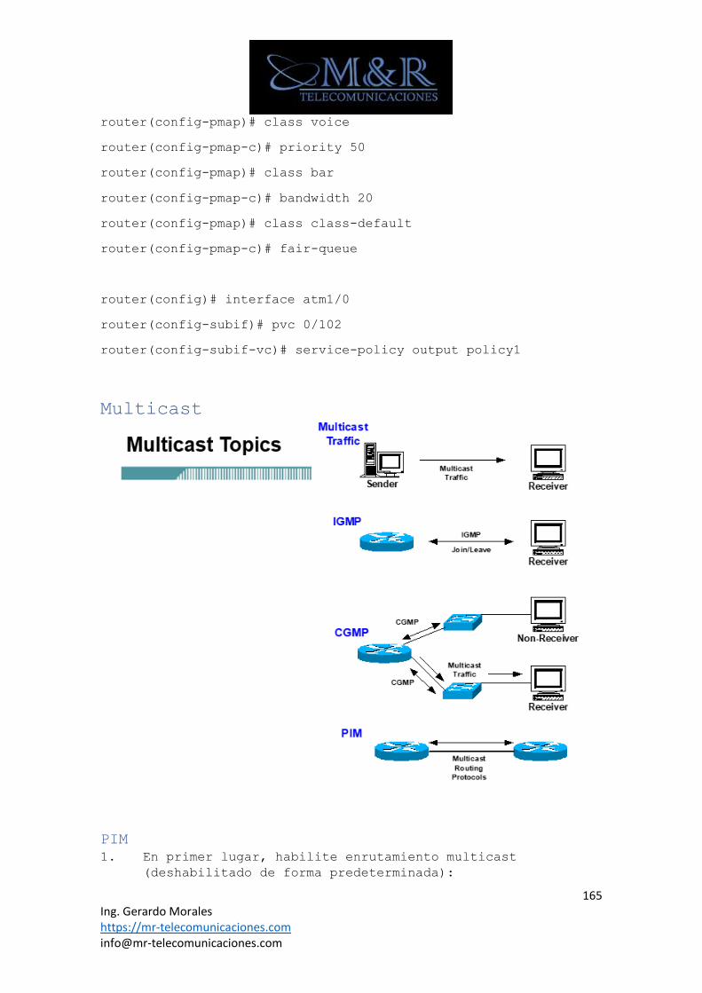
165 Ing. Gerardo Morales https://mr-telecomunicaciones.com [email protected]
router(config-pmap)# class voice
router(config-pmap-c)# priority 50
router(config-pmap)# class bar
router(config-pmap-c)# bandwidth 20
router(config-pmap)# class class-default
router(config-pmap-c)# fair-queue
router(config)# interface atm1/0
router(config-subif)# pvc 0/102
router(config-subif-vc)# service-policy output policy1
Multicast
PIM
1. En primer lugar, habilite enrutamiento multicast
(deshabilitado de forma predeterminada):
166 Ing. Gerardo Morales https://mr-telecomunicaciones.com [email protected]
Router(config)#ip multicast-routing
2. A continuación, habilite PIM en cada interfaz.
El método recomendado para habilitar la multidifusión en una interfaz
es el uso de la ip pim sparse-dense-mode
Router(config-if)#ip pim {dense-mode | sparse mode | sparse-
dense-mode}
Configuración RPs
Router(config)#ip pim rp-address <address>
Auto RP
• Configure un agente de asignación para que aprenda acerca
de todos los candidatos RPS, de modo que pueda compicar
una lista de los routers RP para los que grpups y anuncie
la lista a los enrutadores de cliente.
Router(config)#ip pim send-rp-discovery scope <ttl>
• Configure un candidato RP para anunciarse como RP posible
para un rango de multidifusión.
Router(config)#ip pim send-rp-announce <interface> scope <ttl>
BSR
• Definir el BSR
Router(config)#ip pim bsr-candidate <interface> <hashing-
function>
• Configure un candidato RP
Router(config)#ip pim rp-candidate <interface>
IGMP - Internet Group Management Protocol
• El modo de versión 2 de IGMP es el predeterminado para
todos los sistemas que utilicen Cisco IOS Release 11.3 (2)
T o posterior. Para determinar el uso de la versión
actual:
Router#show ip igmp interface type-number
Para cambiar las versiones (sólo por interfaz):
Router(config-if)#ip igmp version {2 | 1}
Configuración de las joins IGMP
Router(config-if)#ip igmp join-group group-address
CGMP
Router(config-if)#ip cgmp
Switch(config) cgmp
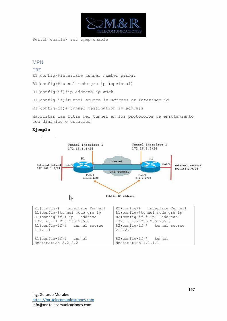
167 Ing. Gerardo Morales https://mr-telecomunicaciones.com [email protected]
Switch(enable) set cgmp enable
VPN
GRE
R1(config)#interface tunnel number global
R1(config)#tunnel mode gre ip (opcional)
R1(config-if)#ip address ip mask
R1(config-if)#tunnel source ip address or interface id
R1(config-if)# tunnel destination ip address
Habilitar las rutas del tunnel en los protocolos de enrutamiento
sea dinámico o estático
Ejemplo
R1(config)# interface Tunnel1
R1(config)#tunnel mode gre ip
R1(config-if)# ip address
172.16.1.1 255.255.255.0
R1(config-if)# tunnel source
1.1.1.1
R1(config-if)# tunnel
destination 2.2.2.2
R2(config)# interface Tunnel1
R1(config)#tunnel mode gre ip
R2(config-if)# ip address
172.16.1.2 255.255.255.0
R2(config-if)# tunnel source
2.2.2.2
R2(config-if)# tunnel
destination 1.1.1.1
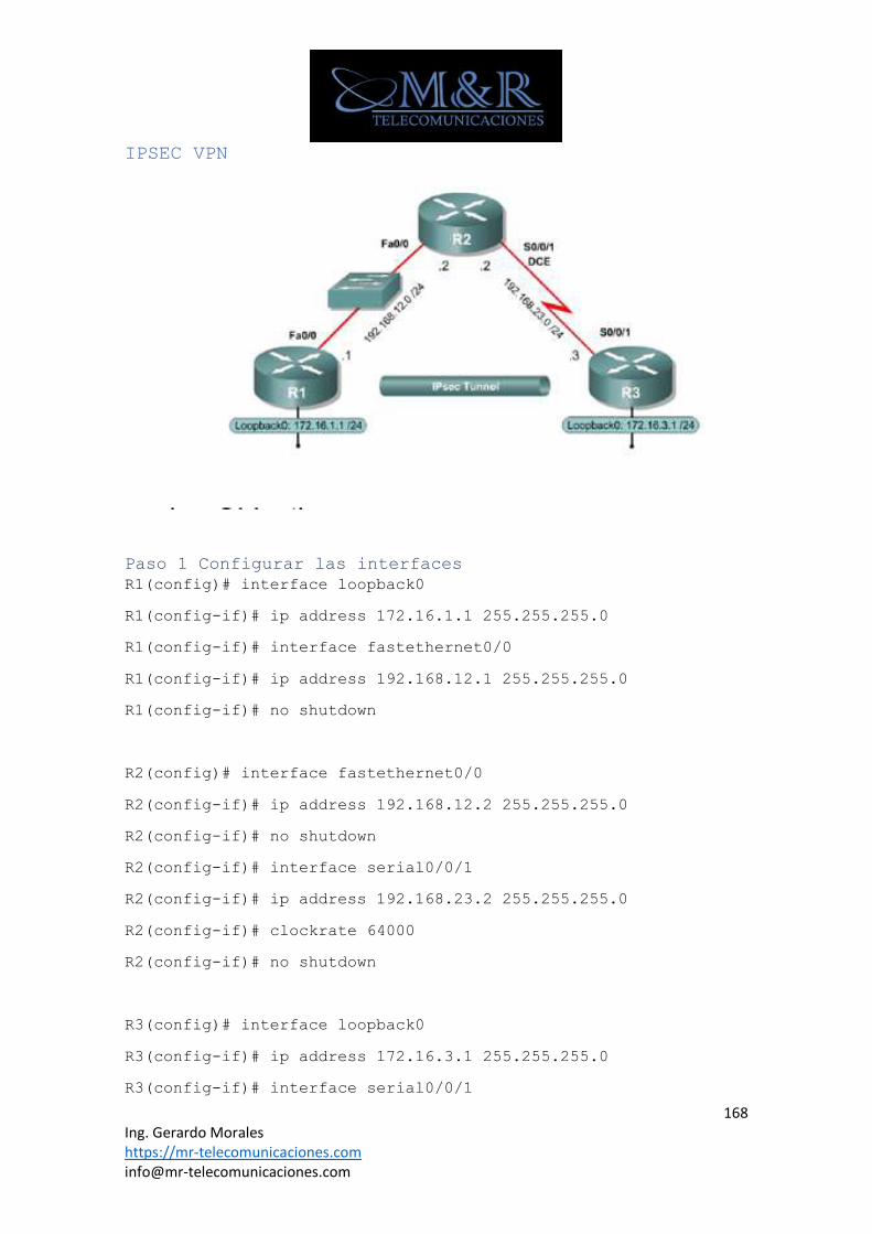
168 Ing. Gerardo Morales https://mr-telecomunicaciones.com [email protected]
IPSEC VPN
Paso 1 Configurar las interfaces
R1(config)# interface loopback0
R1(config-if)# ip address 172.16.1.1 255.255.255.0
R1(config-if)# interface fastethernet0/0
R1(config-if)# ip address 192.168.12.1 255.255.255.0
R1(config-if)# no shutdown
R2(config)# interface fastethernet0/0
R2(config-if)# ip address 192.168.12.2 255.255.255.0
R2(config-if)# no shutdown
R2(config-if)# interface serial0/0/1
R2(config-if)# ip address 192.168.23.2 255.255.255.0
R2(config-if)# clockrate 64000
R2(config-if)# no shutdown
R3(config)# interface loopback0
R3(config-if)# ip address 172.16.3.1 255.255.255.0
R3(config-if)# interface serial0/0/1
169 Ing. Gerardo Morales https://mr-telecomunicaciones.com [email protected]
R3(config-if)# ip address 192.168.23.3 255.255.255.0
R3(config-if)# no shutdown
Paso 2 Configurar EIGRP
R1(config)# router eigrp 1
R1(config-router)# no auto-summary
R1(config-router)# network 172.16.0.0
R1(config-router)# network 192.168.12.0
R2(config)# router eigrp 1
R2(config-router)# no auto-summary
R2(config-router)# network 192.168.12.0
R2(config-router)# network 192.168.23.0
R3(config)# router eigrp 1
R3(config-router)# no auto-summary
R3(config-router)# network 172.16.0.0
R3(config-router)# network 192.168.23.0
Paso 3 Crear Políticas IKE
R1(config)# crypto isakmp enable
R1(config)# crypto isakmp policy 10
R1(config)# crypto isakmp policy
10
R1(config-isakmp)#authentication
pre-shared
R1(config-isakmp)#encryption aes
256
R1(config-isakmp)#hash sha
R1(config-isakmp)#group 5
R1(config-isakmp)#lifetime 3600
R1(config)# crypto isakmp policy
10
R1(config-isakmp)#authentication
pre-shared
R1(config-isakmp)#encryption aes
256
R1(config-isakmp)#hash sha
R1(config-isakmp)#group 5
R1(config-isakmp)#lifetime 3600
Paso 4 Configurar pre-shared keys
R(config)#crypto isakmp key key-string address address
R1(config)# cypto isakamp key cisco address 192.168.23.3
R3(config)# cypto isakamp key cisco address 192.168.12.1

170 Ing. Gerardo Morales https://mr-telecomunicaciones.com [email protected]
Paso 5 configurar IPsec transform set Lifetimes
R1(config)#crypto ipsec transform-set 50 esp-aes esp-sha-hmac
ah-sha-hmac
Paso 6 definir interesting traffic
R1(config)# access-list 101 permit ip 172.16.1.0 0.0.0.255
172.16.3.0 0.0.0.255
R3(config)# access-list 101 permit ip 172.16.3.0 0.0.0.255
172.16.1.0 0.0.0.255
Paso 7 Crear y aplicar Crypto Maps
R1(config)# crypto map MYMAP 10 ipsec-isakamp
R1(config-crypto-map)# match address 101
R1(config-crypto-map)# set peer 192.168.23.3
R1(config-crypto-map)# set pfs group5
R1(config-crypto-map)# set transform-set 50
R1(config-crypto-map)# set security-association lifetime seconds
900
R1(config)#interface fastethernet 0/0
R1(config-if)# crypto map MYMAP
R3(config)# interface serial0/0/1
R3(config-if)#crypto-map MYMAP
Paso 8 Verificar Ipsec configuration
R1# show crypto ipsec transform-set
R1# show crypto map
Paso 9 Verificar operación IPSEC
R1#show crypto isakmp sa
R3#show crypto isakmp sa
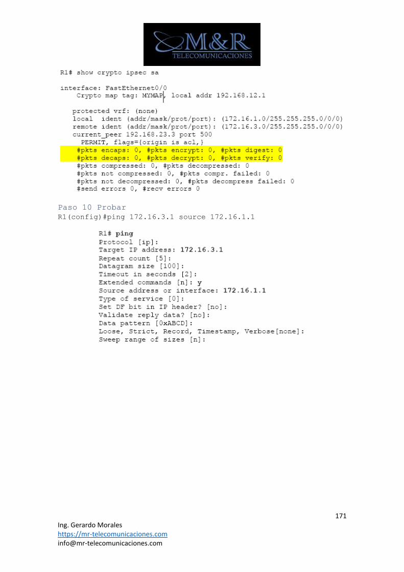
171 Ing. Gerardo Morales https://mr-telecomunicaciones.com [email protected]
Paso 10 Probar
R1(config)#ping 172.16.3.1 source 172.16.1.1
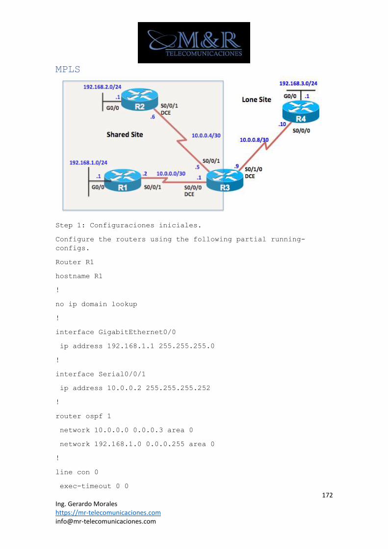
172 Ing. Gerardo Morales https://mr-telecomunicaciones.com [email protected]
MPLS
Step 1: Configuraciones iniciales.
Configure the routers using the following partial running-
configs.
Router R1
hostname R1
!
no ip domain lookup
!
interface GigabitEthernet0/0
ip address 192.168.1.1 255.255.255.0
!
interface Serial0/0/1
ip address 10.0.0.2 255.255.255.252
!
router ospf 1
network 10.0.0.0 0.0.0.3 area 0
network 192.168.1.0 0.0.0.255 area 0
!
line con 0
exec-timeout 0 0
173 Ing. Gerardo Morales https://mr-telecomunicaciones.com [email protected]
logging synchronous
end
Router R2
hostname R2
!
no ip domain lookup
!
interface GigabitEthernet0/0
ip address 192.168.2.1 255.255.255.0
!
interface Serial0/0/1
ip address 10.0.0.6 255.255.255.252
clock rate 64000
!
router ospf 1
network 10.0.0.4 0.0.0.3 area 0
network 192.168.2.0 0.0.0.255 area 0
!
line con 0
exec-timeout 0 0
logging synchronous
end
Router R3
hostname R3
!
interface Serial0/0/0
ip address 10.0.0.1 255.255.255.252
clock rate 64000
174 Ing. Gerardo Morales https://mr-telecomunicaciones.com [email protected]
!
interface Serial0/0/1
ip address 10.0.0.5 255.255.255.252
!
interface Serial0/1/0
ip address 10.0.0.9 255.255.255.252
clock rate 64000
!
router ospf 1
network 10.0.0.0 0.0.0.255 area 0
!
line con 0
exec-timeout 0 0
logging synchronous
end
Router R4
hostname R4
!
no ip domain lookup
!
interface GigabitEthernet0/0
ip address 192.168.3.1 255.255.255.0
!
interface Serial0/0/0
ip address 10.0.0.10 255.255.255.252
!
router ospf 1
network 10.0.0.8 0.0.0.3 area 0
network 192.168.3.0 0.0.0.255 area 0
175 Ing. Gerardo Morales https://mr-telecomunicaciones.com [email protected]
!
line con 0
exec-timeout 0 0
logging synchronous
end
Step 2: Verifique el alcance.
a. After configuring the routers, all routers should be able
to reach all networks.
R3# show ip interface brief
Interface IP-Address OK? Method Status
Protocol
Embedded-Service-Engine0/0 unassigned YES unset
administratively down down
GigabitEthernet0/0 unassigned YES unset
administratively down down
GigabitEthernet0/1 unassigned YES unset
administratively down down
Serial0/0/0 10.0.0.1 YES manual up
up
Serial0/0/1 10.0.0.5 YES manual up
up
Serial0/1/0 10.0.0.9 YES manual up
up
Serial0/1/1 unassigned YES unset
administratively down down
R3#
R3#
R3# show ip ospf neighbor
176 Ing. Gerardo Morales https://mr-telecomunicaciones.com [email protected]
Neighbor ID Pri State Dead Time Address
Interface
192.168.3.1 0 FULL/ - 00:00:32 10.0.0.10
Serial0/1/0
192.168.2.1 0 FULL/ - 00:00:38 10.0.0.6
Serial0/0/1
192.168.1.1 0 FULL/ - 00:00:32 10.0.0.2
Serial0/0/0
R3#
R3# show ip route ospf
Codes: L - local, C - connected, S - static, R - RIP, M -
mobile, B - BGP
D - EIGRP, EX - EIGRP external, O - OSPF, IA - OSPF inter
area
N1 - OSPF NSSA external type 1, N2 - OSPF NSSA external
type 2
E1 - OSPF external type 1, E2 - OSPF external type 2
i - IS-IS, su - IS-IS summary, L1 - IS-IS level-1, L2 -
IS-IS level-2
ia - IS-IS inter area, * - candidate default, U - per-
user static route
o - ODR, P - periodic downloaded static route, H - NHRP,
l - LISP
a - application route
+ - replicated route, % - next hop override
Gateway of last resort is not set
O 192.168.1.0/24 [110/65] via 10.0.0.2, 00:07:30,
Serial0/0/0
O 192.168.2.0/24 [110/65] via 10.0.0.6, 00:07:30,
Serial0/0/1
O 192.168.3.0/24 [110/65] via 10.0.0.10, 00:07:30,
Serial0/1/0
177 Ing. Gerardo Morales https://mr-telecomunicaciones.com [email protected]
R3#
R1# show ip route ospf
Codes: L - local, C - connected, S - static, R - RIP, M -
mobile, B - BGP
D - EIGRP, EX - EIGRP external, O - OSPF, IA - OSPF inter
area
N1 - OSPF NSSA external type 1, N2 - OSPF NSSA external
type 2
E1 - OSPF external type 1, E2 - OSPF external type 2
i - IS-IS, su - IS-IS summary, L1 - IS-IS level-1, L2 -
IS-IS level-2
ia - IS-IS inter area, * - candidate default, U - per-
user static route
o - ODR, P - periodic downloaded static route, H - NHRP,
l - LISP
a - application route
+ - replicated route, % - next hop override
Gateway of last resort is not set
10.0.0.0/8 is variably subnetted, 4 subnets, 2 masks
O 10.0.0.4/30 [110/128] via 10.0.0.1, 00:00:13,
Serial0/0/1
O 10.0.0.8/30 [110/128] via 10.0.0.1, 00:00:13,
Serial0/0/1
O 192.168.2.0/24 [110/129] via 10.0.0.1, 00:00:03,
Serial0/0/1
O 192.168.3.0/24 [110/129] via 10.0.0.1, 00:00:03,
Serial0/0/1
R1#
R1# ping 192.168.2.1
178 Ing. Gerardo Morales https://mr-telecomunicaciones.com [email protected]
Type escape sequence to abort.
Sending 5, 100-byte ICMP Echos to 192.168.2.1, timeout is 2
seconds:
!!!!!
Success rate is 100 percent (5/5), round-trip min/avg/max =
56/58/68 ms
R1# ping 192.168.3.1
Type escape sequence to abort.
Sending 5, 100-byte ICMP Echos to 192.168.3.1, timeout is 2
seconds:
!!!!!
Success rate is 100 percent (5/5), round-trip min/avg/max =
52/55/56 ms
R1#
Step 3: Configure VRF-Lite.
a. La configuración del reenvío de VRF en una interfaz con el
comando IP VRF reenvío elimina todas las direcciones IP de esa
interfaz. Las interfaces deben tener las direcciones IP re-
configuradas. Necesitará un proceso OSPF independiente para cada
VRF.
R3(config)# ip vrf SharedSites
R3(config-vrf)# exit
R3(config)# ip vrf LoneSite
R3(config-vrf)# exit
R3(config)#
R3(config)# interface s 0/0/0
R3(config-if)# ip vrf forwarding SharedSites
% Interface Serial0/0/0 IPv4 disabled and address(es) removed
due to disabling VRF SharedSites
*Jan 15 23:38:23.827: %OSPF-5-ADJCHG: Process 1, Nbr 192.168.1.1
on Serial0/0/0 from FULL to DOWN, Neighbor Down: Interface down
or detached
179 Ing. Gerardo Morales https://mr-telecomunicaciones.com [email protected]
R3(config-if)# ip address 10.0.0.1 255.255.255.252
R3(config-if)# exit
R3(config)#
R3(config)# interface s 0/0/1
R3(config-if)# ip vrf forwarding SharedSites
% Interface Serial0/0/1 IPv4 disabled and address(es) removed
due to disabling VRF SharedSites
*Jan 15 23:38:56.287: %OSPF-5-ADJCHG: Process 1, Nbr 192.168.2.1
on Serial0/0/1 from FULL to DOWN, Neighbor Down: Interface down
or detached
R3(config-if)# ip address 10.0.0.5 255.255.255.252
R3(config-if)# exit
R3(config)#
R3(config)# interface s 0/1/0
R3(config-if)# ip vrf forwarding LoneSite
% Interface Serial0/1/0 IPv4 disabled and address(es) removed
due to disabling VRF LoneSite
*Jan 15 23:39:32.447: %OSPF-5-ADJCHG: Process 1, Nbr 192.168.3.1
on Serial0/1/0 from FULL to DOWN, Neighbor Down: Interface down
or detached
R3(config-if)# ip address 10.0.0.9 255.255.255.252
R3(config-if)# exit
R3(config)#
R3(config)# no router ospf 1
R3(config)#
R3(config)# router ospf 1 vrf SharedSites
R3(config-router)# network 10.0.0.0 0.0.0.255 area 0
*Jan 15 23:41:52.767: %OSPF-5-ADJCHG: Process 1, Nbr 192.168.2.1
on Serial0/0/1 from LOADING to FULL, Loading Done
*Jan 15 23:41:52.771: %OSPF-5-ADJCHG: Process 1, Nbr 192.168.1.1
on Serial0/0/0 from LOADING to FULL, Loading Done
180 Ing. Gerardo Morales https://mr-telecomunicaciones.com [email protected]
R3(config-router)# exit
R3(config)#
R3(config)# router ospf 2 vrf LoneSite
R3(config-router)# network 10.0.0.0 0.0.0.255 area 0
*Jan 15 23:42:26.027: %OSPF-5-ADJCHG: Process 2, Nbr 192.168.3.1
on Serial0/1/0 from LOADING to FULL, Loading Done
R3(config-router)# exit
R3(config)#
R3#
Step 4: Verify VRF-Lite.
Verify VRF-Lite.
Router R3
R3# show ip route
Codes: L - local, C - connected, S - static, R - RIP, M -
mobile, B - BGP
D - EIGRP, EX - EIGRP external, O - OSPF, IA - OSPF inter
area
N1 - OSPF NSSA external type 1, N2 - OSPF NSSA external
type 2
E1 - OSPF external type 1, E2 - OSPF external type 2
i - IS-IS, su - IS-IS summary, L1 - IS-IS level-1, L2 -
IS-IS level-2
ia - IS-IS inter area, * - candidate default, U - per-
user static route
o - ODR, P - periodic downloaded static route, H - NHRP,
l - LISP
a - application route
+ - replicated route, % - next hop override
Gateway of last resort is not set
181 Ing. Gerardo Morales https://mr-telecomunicaciones.com [email protected]
R3#
R3# show ip route vrf SharedSites
Routing Table: SharedSites
Codes: L - local, C - connected, S - static, R - RIP, M -
mobile, B - BGP
D - EIGRP, EX - EIGRP external, O - OSPF, IA - OSPF inter
area
N1 - OSPF NSSA external type 1, N2 - OSPF NSSA external
type 2
E1 - OSPF external type 1, E2 - OSPF external type 2
i - IS-IS, su - IS-IS summary, L1 - IS-IS level-1, L2 -
IS-IS level-2
ia - IS-IS inter area, * - candidate default, U - per-
user static route
o - ODR, P - periodic downloaded static route, H - NHRP,
l - LISP
a - application route
+ - replicated route, % - next hop override
Gateway of last resort is not set
10.0.0.0/8 is variably subnetted, 4 subnets, 2 masks
C 10.0.0.0/30 is directly connected, Serial0/0/0
L 10.0.0.1/32 is directly connected, Serial0/0/0
C 10.0.0.4/30 is directly connected, Serial0/0/1
L 10.0.0.5/32 is directly connected, Serial0/0/1
O 192.168.1.0/24 [110/65] via 10.0.0.2, 00:02:35,
Serial0/0/0
O 192.168.2.0/24 [110/65] via 10.0.0.6, 00:02:35,
Serial0/0/1
182 Ing. Gerardo Morales https://mr-telecomunicaciones.com [email protected]
R3#
R3# show ip route vrf LoneSite
Routing Table: LoneSite
Codes: L - local, C - connected, S - static, R - RIP, M -
mobile, B - BGP
D - EIGRP, EX - EIGRP external, O - OSPF, IA - OSPF inter
area
N1 - OSPF NSSA external type 1, N2 - OSPF NSSA external
type 2
E1 - OSPF external type 1, E2 - OSPF external type 2
i - IS-IS, su - IS-IS summary, L1 - IS-IS level-1, L2 -
IS-IS level-2
ia - IS-IS inter area, * - candidate default, U - per-
user static route
o - ODR, P - periodic downloaded static route, H - NHRP,
l - LISP
a - application route
+ - replicated route, % - next hop override
Gateway of last resort is not set
10.0.0.0/8 is variably subnetted, 2 subnets, 2 masks
C 10.0.0.8/30 is directly connected, Serial0/1/0
L 10.0.0.9/32 is directly connected, Serial0/1/0
O 192.168.3.0/24 [110/65] via 10.0.0.10, 00:02:26,
Serial0/1/0
R3#
R3# show ip vrf
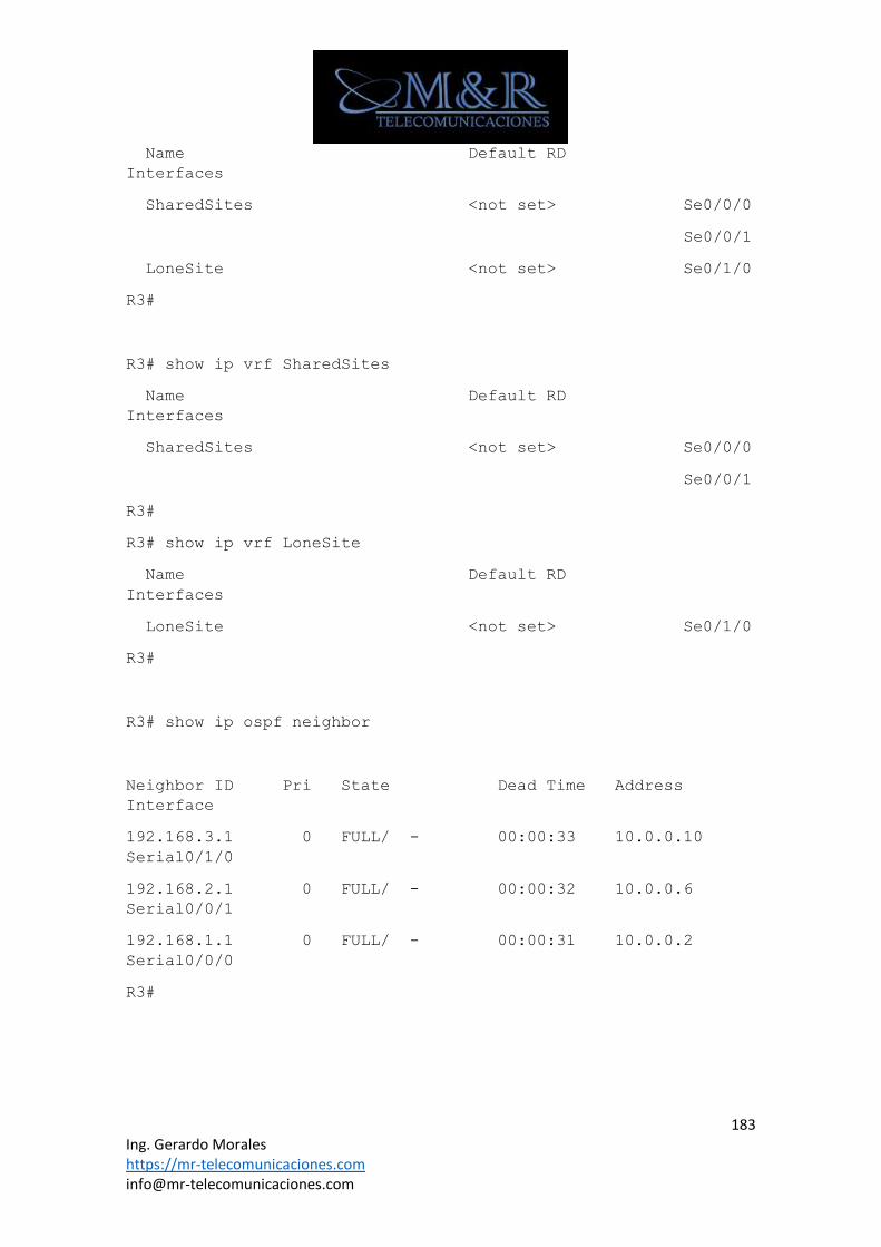
183 Ing. Gerardo Morales https://mr-telecomunicaciones.com [email protected]
Name Default RD
Interfaces
SharedSites <not set> Se0/0/0
Se0/0/1
LoneSite <not set> Se0/1/0
R3#
R3# show ip vrf SharedSites
Name Default RD
Interfaces
SharedSites <not set> Se0/0/0
Se0/0/1
R3#
R3# show ip vrf LoneSite
Name Default RD
Interfaces
LoneSite <not set> Se0/1/0
R3#
R3# show ip ospf neighbor
Neighbor ID Pri State Dead Time Address
Interface
192.168.3.1 0 FULL/ - 00:00:33 10.0.0.10
Serial0/1/0
192.168.2.1 0 FULL/ - 00:00:32 10.0.0.6
Serial0/0/1
192.168.1.1 0 FULL/ - 00:00:31 10.0.0.2
Serial0/0/0
R3#
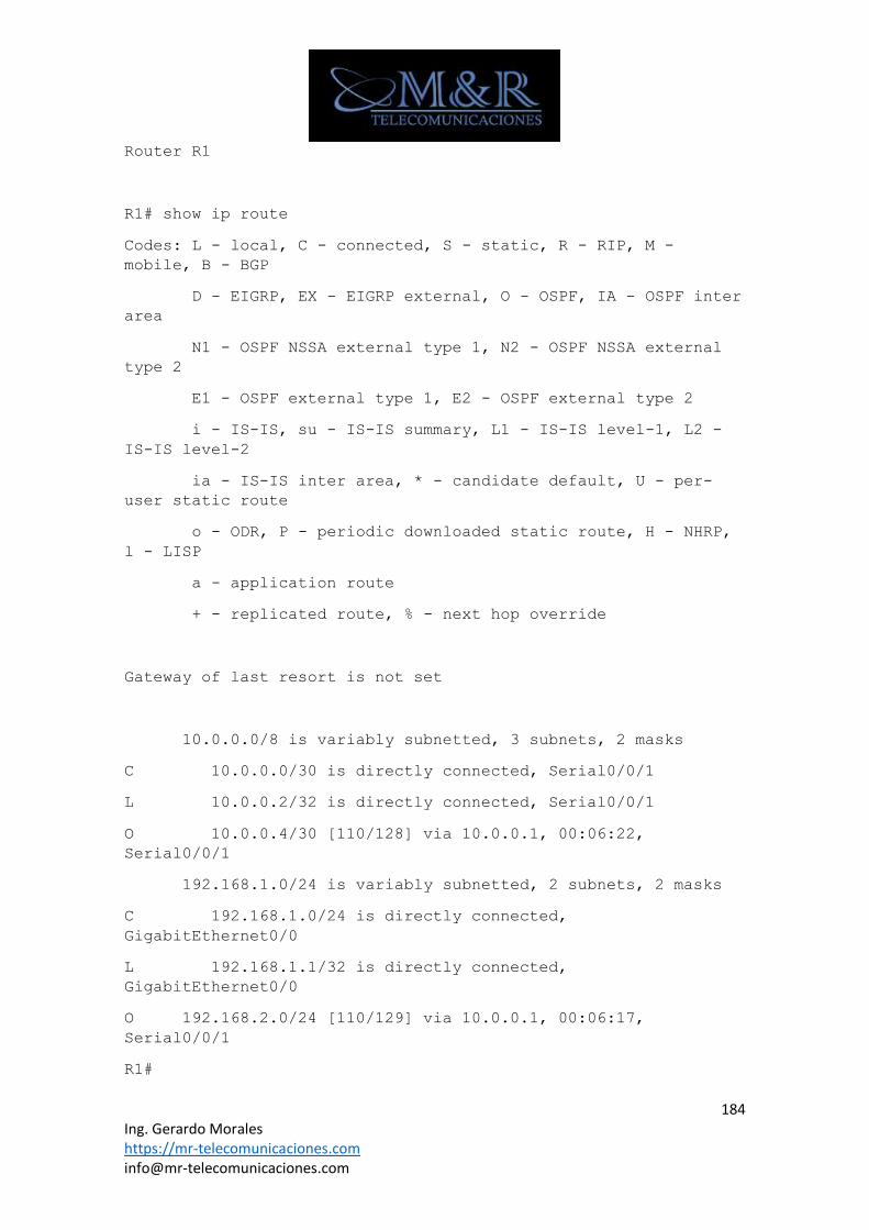
184 Ing. Gerardo Morales https://mr-telecomunicaciones.com [email protected]
Router R1
R1# show ip route
Codes: L - local, C - connected, S - static, R - RIP, M -
mobile, B - BGP
D - EIGRP, EX - EIGRP external, O - OSPF, IA - OSPF inter
area
N1 - OSPF NSSA external type 1, N2 - OSPF NSSA external
type 2
E1 - OSPF external type 1, E2 - OSPF external type 2
i - IS-IS, su - IS-IS summary, L1 - IS-IS level-1, L2 -
IS-IS level-2
ia - IS-IS inter area, * - candidate default, U - per-
user static route
o - ODR, P - periodic downloaded static route, H - NHRP,
l - LISP
a - application route
+ - replicated route, % - next hop override
Gateway of last resort is not set
10.0.0.0/8 is variably subnetted, 3 subnets, 2 masks
C 10.0.0.0/30 is directly connected, Serial0/0/1
L 10.0.0.2/32 is directly connected, Serial0/0/1
O 10.0.0.4/30 [110/128] via 10.0.0.1, 00:06:22,
Serial0/0/1
192.168.1.0/24 is variably subnetted, 2 subnets, 2 masks
C 192.168.1.0/24 is directly connected,
GigabitEthernet0/0
L 192.168.1.1/32 is directly connected,
GigabitEthernet0/0
O 192.168.2.0/24 [110/129] via 10.0.0.1, 00:06:17,
Serial0/0/1
R1#
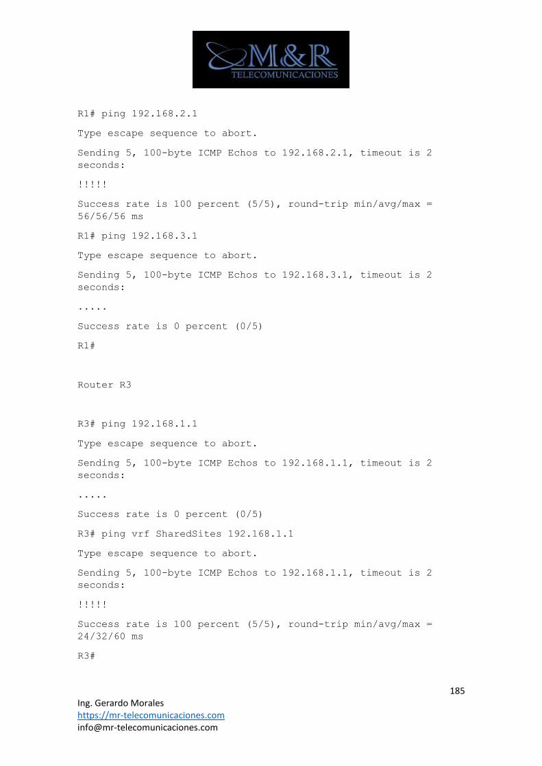
185 Ing. Gerardo Morales https://mr-telecomunicaciones.com [email protected]
R1# ping 192.168.2.1
Type escape sequence to abort.
Sending 5, 100-byte ICMP Echos to 192.168.2.1, timeout is 2
seconds:
!!!!!
Success rate is 100 percent (5/5), round-trip min/avg/max =
56/56/56 ms
R1# ping 192.168.3.1
Type escape sequence to abort.
Sending 5, 100-byte ICMP Echos to 192.168.3.1, timeout is 2
seconds:
.....
Success rate is 0 percent (0/5)
R1#
Router R3
R3# ping 192.168.1.1
Type escape sequence to abort.
Sending 5, 100-byte ICMP Echos to 192.168.1.1, timeout is 2
seconds:
.....
Success rate is 0 percent (0/5)
R3# ping vrf SharedSites 192.168.1.1
Type escape sequence to abort.
Sending 5, 100-byte ICMP Echos to 192.168.1.1, timeout is 2
seconds:
!!!!!
Success rate is 100 percent (5/5), round-trip min/avg/max =
24/32/60 ms
R3#
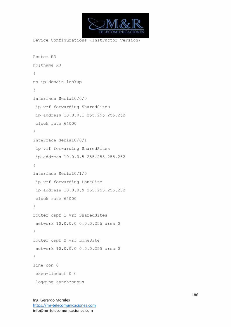
186 Ing. Gerardo Morales https://mr-telecomunicaciones.com [email protected]
Device Configurations (Instructor version)
Router R3
hostname R3
!
no ip domain lookup
!
interface Serial0/0/0
ip vrf forwarding SharedSites
ip address 10.0.0.1 255.255.255.252
clock rate 64000
!
interface Serial0/0/1
ip vrf forwarding SharedSites
ip address 10.0.0.5 255.255.255.252
!
interface Serial0/1/0
ip vrf forwarding LoneSite
ip address 10.0.0.9 255.255.255.252
clock rate 64000
!
router ospf 1 vrf SharedSites
network 10.0.0.0 0.0.0.255 area 0
!
router ospf 2 vrf LoneSite
network 10.0.0.0 0.0.0.255 area 0
!
line con 0
exec-timeout 0 0
logging synchronous

187 Ing. Gerardo Morales https://mr-telecomunicaciones.com [email protected]