MAESTRIA EN TECNOLOGIAS APLICADAS A LA EDUCACIÓN TEORÌAS DEL APRENDIZAJE
Upload
gabriel114Category
view
219download
0
8/3/2019 Guia de selección de tecnologias aplicadas a derrames Vol II
http://slidepdf.com/reader/full/guia-de-seleccion-de-tecnologias-aplicadas-a-derrames-vol-ii 1/298

8/3/2019 Guia de selección de tecnologias aplicadas a derrames Vol II
http://slidepdf.com/reader/full/guia-de-seleccion-de-tecnologias-aplicadas-a-derrames-vol-ii 2/298
06/30/00
SSeelleeccttiioonn GGuuiiddee f f oorr OOiill SSppiillll AApppplliieedd TTeecchhnnoollooggiieess
VVoolluummee IIII – – OOppeerraattiioonnss PPllaannss
Ann Hayward Walker, Jacqueline Michel, Brad Benggio, Debra Scholz, John Boyd,
and William Walker
Prepared under the Weston SATA Contract No. 68S53002
to EPA Region III, under the Direction of the RRT III Spill Response Countermeasures
Work Group
& in Cooperation with the Regional Response Team from Region IV
and the NOAA Hazardous Materials Response & Assessment Division
Scientific and Environmental Associates, Inc.
325 Mason Avenue
Cape Charles, Virginia 23310
Tel. 757-331-1787, fax –1788, email [email protected]
NOTE: This draft of Volume II of the “Selection Guide for Oil
Spill Applied Technologies” reflects many changesfrom the previous versions. This is also the first draftof this document to be available in PDF format inorder to allow internet access to the document byusers. Currently, this working draft does NOT includedetailed linkages to the various sections within thisdocument.
8/3/2019 Guia de selección de tecnologias aplicadas a derrames Vol II
http://slidepdf.com/reader/full/guia-de-seleccion-de-tecnologias-aplicadas-a-derrames-vol-ii 3/298
ii
6/30/00
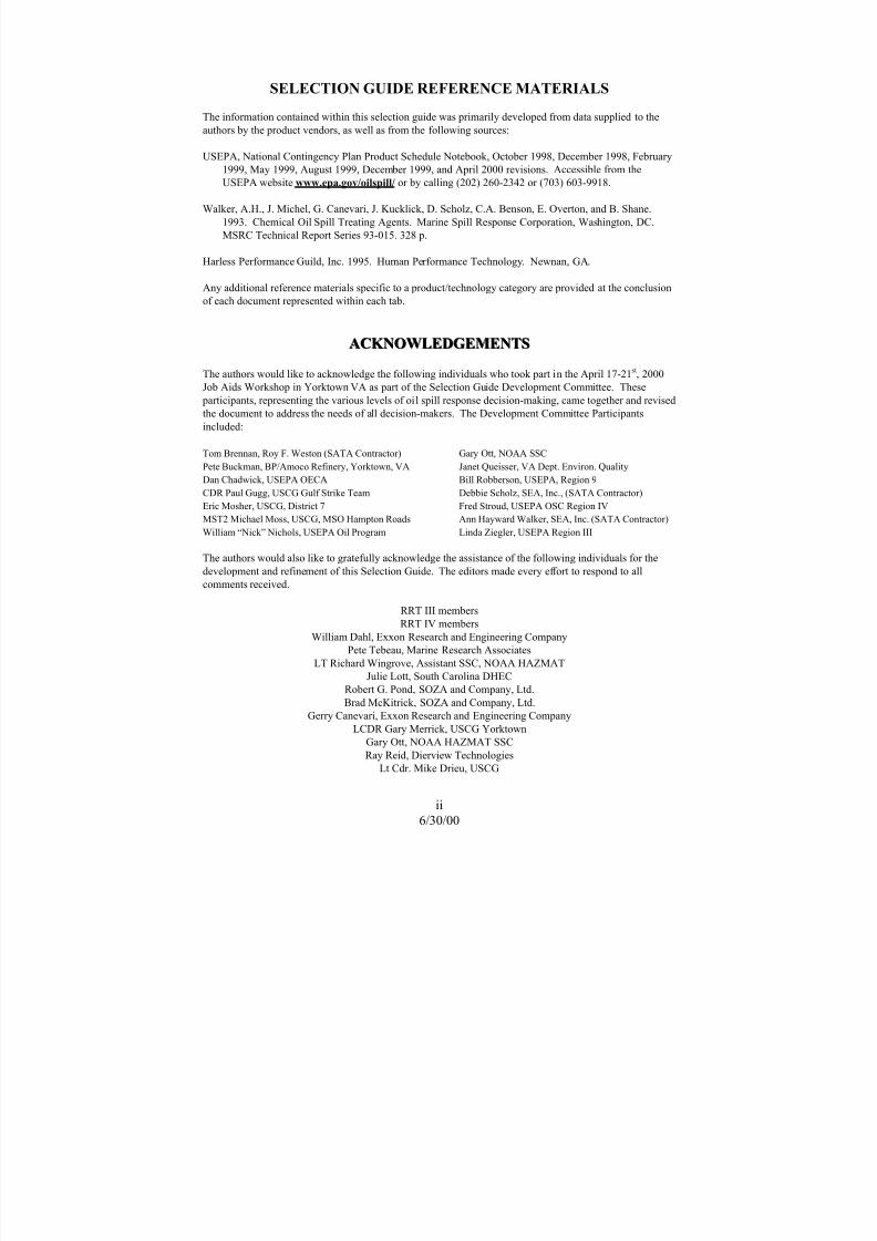
SELECTION GUIDE REFERENCE MATERIALS
The information contained within this selection guide was primarily developed from data supplied to the
authors by the product vendors, as well as from the following sources:
USEPA, National Contingency Plan Product Schedule Notebook, October 1998, December 1998, February
1999, May 1999, August 1999, December 1999, and April 2000 revisions. Accessible from theUSEPA website www.epa.gov/oilspill/ or by calling (202) 260-2342 or (703) 603-9918.
Walker, A.H., J. Michel, G. Canevari, J. Kucklick, D. Scholz, C.A. Benson, E. Overton, and B. Shane.
1993. Chemical Oil Spill Treating Agents. Marine Spill Response Corporation, Washington, DC.
MSRC Technical Report Series 93-015. 328 p.
Harless Performance Guild, Inc. 1995. Human Performance Technology. Newnan, GA.
Any additional reference materials specific to a product/technology category are provided at the conclusion
of each document represented within each tab.
AACCK K NNOOWWLLEEDDGGEEMMEENNTTSS
The authors would like to acknowledge the following individuals who took part in the April 17-21st, 2000
Job Aids Workshop in Yorktown VA as part of the Selection Guide Development Committee. These
participants, representing the various levels of oil spill response decision-making, came together and revised
the document to address the needs of all decision-makers. The Development Committee Participants
included:
Tom Brennan, Roy F. Weston (SATA Contractor)
Pete Buckman, BP/Amoco Refinery, Yorktown, VA
Dan Chadwick, USEPA OECA
CDR Paul Gugg, USCG Gulf Strike Team
Eric Mosher, USCG, District 7
MST2 Michael Moss, USCG, MSO Hampton Roads
William “Nick” Nichols, USEPA Oil Program
Gary Ott, NOAA SSC
Janet Queisser, VA Dept. Environ. Quality
Bill Robberson, USEPA, Region 9
Debbie Scholz, SEA, Inc., (SATA Contractor)
Fred Stroud, USEPA OSC Region IV
Ann Hayward Walker, SEA, Inc. (SATA Contractor)
Linda Ziegler, USEPA Region III
The authors would also like to gratefully acknowledge the assistance of the following individuals for the
development and refinement of this Selection Guide. The editors made every effort to respond to all
comments received.
RRT III members
RRT IV members
William Dahl, Exxon Research and Engineering Company
Pete Tebeau, Marine Research Associates
LT Richard Wingrove, Assistant SSC, NOAA HAZMAT
Julie Lott, South Carolina DHEC
Robert G. Pond, SOZA and Company, Ltd.
Brad McKitrick, SOZA and Company, Ltd.
Gerry Canevari, Exxon Research and Engineering Company
LCDR Gary Merrick, USCG Yorktown
Gary Ott, NOAA HAZMAT SSC
Ray Reid, Dierview Technologies
Lt Cdr. Mike Drieu, USCG

8/3/2019 Guia de selección de tecnologias aplicadas a derrames Vol II
http://slidepdf.com/reader/full/guia-de-seleccion-de-tecnologias-aplicadas-a-derrames-vol-ii 4/298
iii
6/30/00
FFR R OONNTT CCOOVVEER R PPHHOOTTOO CCR R EEDDIITTSS
National Oceanic and Atmospheric Administration Web Page Photo Gallery
US Coast Guard Web Page Photo Gallery
Hyattsville, MD, Volunteer Fire Department Web Page Photo Gallery
Boise, ID Fire Department Web Page Photo Gallery

8/3/2019 Guia de selección de tecnologias aplicadas a derrames Vol II
http://slidepdf.com/reader/full/guia-de-seleccion-de-tecnologias-aplicadas-a-derrames-vol-ii 5/298
iv
6/30/00
This page intentionally left blank

8/3/2019 Guia de selección de tecnologias aplicadas a derrames Vol II
http://slidepdf.com/reader/full/guia-de-seleccion-de-tecnologias-aplicadas-a-derrames-vol-ii 6/298
v
6/30/00
SELECTION GUIDE OVERVIEW
Context The first line of oil spill cleanup operations on surface waters has
been, and will continue to be, mechanical countermeasures such
as booms and skimmers. However, when the limitations of mechanical countermeasures are met and oil threatens or
continues to threaten the public interest or the environment, other
response countermeasures and technologies should be
considered. The effective and timely evaluation of these
countermeasures may play a critical role in a successful oil spill
response.
This Selection Guide is a compilation of information and
guidance on the use of oil spill response technologies and actions
that may be unfamiliar to Federal or state on-scene coordinators
or local incident commanders. This Guide has been developed to
provide the oil spill decision-maker with a tool that provides all
the information required to make a decision regarding the use of
a particular applied technology product or countermeasure. This
volume provides a placeholder for region-specific and well as
nationally recognized implementation and operation planning
information for the use of these applied technologies.
About The Selection
Guide
The primary objective of this guide is to provide guidance
rocedures to implement and monitor the use of applied
technologies during oil spill response operations. Much of theinformation in Volume 2 is region-specific.
Scope The Selection Guide includes information on the implementation
and operational use of applied technologies to counter the effects
of spilled oil on land, on inland waters (fresh and estuarine), and
coastal waters.
Updates And
Website Access
This volume of the Selection Guide provides the decision-maker
with a placeholder to retain and maintain all guidance
information regarding the use of applied technologies.
The goal is to post the Selection Guide on a Website to facilitate
easy access and information exchange among regions, and
regularly update it as new information and guidance materials
become available.

8/3/2019 Guia de selección de tecnologias aplicadas a derrames Vol II
http://slidepdf.com/reader/full/guia-de-seleccion-de-tecnologias-aplicadas-a-derrames-vol-ii 7/298
vi
6/30/00
SELECTION GUIDE OVERVIEW (CONTINUED)
Intended Users The intended users for this guide are all oil spill decision-
makers, both experienced and less experienced. They include
members of the Unified Command, e.g., FOSC, SOSC, Incident
Commander, and resource trustees, among others.
When to Use The guide should be used:
§ During spill response by the Planning Section.
§ During pre-spill planning in developing Area
Contingency Plans and Facility Response Plans.
This volume was designed to provide oil spill decision-makers
with a single resource that would contain all of the regional-
specific guidance and requirements for the use of applied
technologies.
Development
Background This Selection Guide has been developed under the Work Plan of
the Region III Regional Response Team Spill Response
Countermeasures Work Group in cooperation with the Region IV
Regional Response Team.
Comments from USEPA, USCG, and State OSCs and resource
trustees representing Regions 3, 4, and 9 have guided the
development of this Selection Guide, along with the input of the
Selection Guide Development Committee.
Continued on Next Page

8/3/2019 Guia de selección de tecnologias aplicadas a derrames Vol II
http://slidepdf.com/reader/full/guia-de-seleccion-de-tecnologias-aplicadas-a-derrames-vol-ii 8/298
vii
6/30/00
TTAABBLLEE OOFF CCOONNTTEENNTTSS PAGE
SELECTION GUIDE R EFERENCE MATERIALS ................................................... ii
ACKNOWLEDGEMENTS....................................................................................... ii
FRONT COVER PHOTO CREDITS............................................................................ iii
SELECTION GUIDE OVERVIEW ............................................................................... v
TABLE OF CONTENTS ......................................................................................... vii
TAB 1: DISPERSANT IMPLEMENTATION/OPERATIONS PLAN
DRAFT : Region III Dispersant Operation Plan
TAB 2: BIOREMEDIATION PLAN
Region IV Bioremediation Plan
NRT Bioremediation Fact Sheet
TAB 3: OTHER COUNTERMEASURES PLANS
Region III ISB Evaluation & Response Checklist
Region IV Inland ISB Plan
TAB 4: MONITORING PLANS/STRATEGIES
Special Monitoring of Applied Response Technologies (SMART)
TAB 5: APPENDICES
Region III Memorandum of Understanding for Dispersants
Region III Memorandum of Understanding for In situ Burning

8/3/2019 Guia de selección de tecnologias aplicadas a derrames Vol II
http://slidepdf.com/reader/full/guia-de-seleccion-de-tecnologias-aplicadas-a-derrames-vol-ii 9/298
viii
6/30/00
This page intentionally left blank

8/3/2019 Guia de selección de tecnologias aplicadas a derrames Vol II
http://slidepdf.com/reader/full/guia-de-seleccion-de-tecnologias-aplicadas-a-derrames-vol-ii 10/298
1
6/30/00
DDIISSPPEER R SSAANNTTSS OOPPEER R AATTIIOONNSS IIMMPPLLEEMMEENNTTAATTIIOONN PPLLAANN
IntroductionThis section of the Selection Guide provides a plan for
implementing dispersant application during oil pill response
operations. Guidance is provided for the Area Planning process,
including recommended checklists for emergency response.Recommended implementation of the Plan involves
customization by the FOSC/Area Committee and integration into
the Area Contingency Plan (ACP).
Purpose The Dispersant Operations Implementation Plan (DOIP) is
intended to provide interim guidance for dispersant operations in
the emergency phase of an oil spill response operation.
Customization and integration into the ACP will result in a more
complete and powerful dispersant response tool. Much of guidance in this DOIP was extracted from the recently ratified
Region IV Dispersants Operations Plan, which remains a stand-
alone document for Region IV.
Note Ideally, implementation plans will be developed prior to an
incident for those technologies that have pre-approval, like
dispersants, or those that have been through the ARTES process.
If a decision is made to use an optional tool and approval is
obtained for a product that lacks a previously developed
implementation plan, an incident-specific plan will be developedand added to this section and to the Region III/IV database.

8/3/2019 Guia de selección de tecnologias aplicadas a derrames Vol II
http://slidepdf.com/reader/full/guia-de-seleccion-de-tecnologias-aplicadas-a-derrames-vol-ii 11/298
2
06/30/00
This page intentionally left blank

8/3/2019 Guia de selección de tecnologias aplicadas a derrames Vol II
http://slidepdf.com/reader/full/guia-de-seleccion-de-tecnologias-aplicadas-a-derrames-vol-ii 12/298
R EGION III
Regional Response Team
DISPERSANT OPERATIONS
IMPLEMENTATION PLAN
Draft 6/00

8/3/2019 Guia de selección de tecnologias aplicadas a derrames Vol II
http://slidepdf.com/reader/full/guia-de-seleccion-de-tecnologias-aplicadas-a-derrames-vol-ii 13/298
This Page Intentionally Left Blank

8/3/2019 Guia de selección de tecnologias aplicadas a derrames Vol II
http://slidepdf.com/reader/full/guia-de-seleccion-de-tecnologias-aplicadas-a-derrames-vol-ii 14/298
i
R EGION IIIRegional Response Team
DISPERSANT OPERATIONS
IMPLEMENTATION PLAN
June 30, 2000
PREPARED UNDER THE WESTON SATA CONTRACT NO. 68S53002 TO EPA R EGION III,
UNDER THE DIRECTION OF THE RRT III SPILL R ESPONSE COUNTERMEASURES WORK
GROUP, AND IN COOPERATION WITH THE NATIONAL R ESPONSE TEAM
How to use this plan: For spill response, turn to the next page (page ii) for a high
level response checklist to properly initiate all required dispersant-related activities
upon initial notification of a spill. When properly customized and inserted in the Area
Contingency Plan (ACP), page ii will assign responsibilities and serve as a
“roadmap” to direct assigned personnel to appropriate sections of the DOIP for
implementation guidance. The Table of Contents on page iv provides detail on the
contents of each section of the DOIP. The detailed Table of Contents for each section
is repeated as a response checklist at the beginning of that section to simplify its use
by assigned area personnel. The DOIP Foreword on page iii is not intended for
response, but rather provides guidance for use of the DOIP as a planning tool.

8/3/2019 Guia de selección de tecnologias aplicadas a derrames Vol II
http://slidepdf.com/reader/full/guia-de-seleccion-de-tecnologias-aplicadas-a-derrames-vol-ii 15/298
RRT III Dispersant Operations Implementation Plan
ii WORKING DRAFT 6/00
Checklist and Roadmap
Note: Dispersants are most effective when applied to fresh oil slicks. They lose their
effectiveness over time, and depending on the characteristics of the spilled oil, will generally be
ineffective when the oil has weathered for between 48 to 72 hours or more. This narrow window
of opportunity makes it critical that this implementation plan support early dispersant use
decisions, resource mobilization, incident-specific planning, etc.
Table 1 – DOIP Checklist and Roadmap (below) and the Plan sections that follow are intended to
encourage and support rapid implementation of appropriate actions. Table 1 identifies a series of
Response Phases, provides for identification of individuals responsible for initial implementation of
those phases, and refers these individuals to specific plan pages for implementation guidance. The
sequence and/or concurrent implementation of the following phases will vary with the
circumstances of the incident, as directed by the Federal On-Scene Coordinator/Unified
Command.
Table 1 – DOIP Checklist and Roadmap
√ Dispersant Response Phase 1) Initial ResponsibilityDOIP
Section
Perform NotificationsUSCG MSO (Duty Section)
(Name / Watch, Quarter & Station Bill Assignment)
I
(ACP Page #)
Determine Dispersant Applicability
SSC
(Name / Watch, Quarter & Station Bill Assignment)
II
(ACP Page #)
Obtain Approval for Dispersant Use
SSC (Planning) & FOSC
(Name / Watch, Quarter & Station Bill Assignment)
III
(ACP Page #)
Develop Incident-Specific DispersantOperations Plan
SSC & USCG MSO (Planning)
(Name / Watch, Quarter & Station Bill Assignment)
IV
(ACP Page #)
Mobilize Dispersant Resources
USCG MSO (Logistics)
(Name / Watch, Quarter & Station Bill Assignment)
V
(ACP Page #)
Implement Dispersant Operations Plan
(Incident-Specific)
Operations Section Chief
(Name / Watch, Quarter & Station Bill Assignment)
VI
(ACP Page #)
Implement Monitoring ProtocolUSCG – NSF
_______________________
(Name / Watch, Quarter & Station Bill Assignment)
VII
(ACP Page #)
Coordinate Dispersant Observer ProgramUSCG MSO (Planning)
_______________________ (Name / Watch, Quarter & Station Bill Assignment)
VIII
(ACP Page #)
Demobilize Dispersant ResourcesUSCG MSO (Planning)
_______________________ (Name / Watch, Quarter & Station Bill Assignment)
IX
(ACP Page #)

8/3/2019 Guia de selección de tecnologias aplicadas a derrames Vol II
http://slidepdf.com/reader/full/guia-de-seleccion-de-tecnologias-aplicadas-a-derrames-vol-ii 16/298
RRT III Dispersant Operations Implementation Plan
iii WORKING DRAFT 6/00
FOREWORD
This Dispersant Operations Implementation Plan (DOIP) has been developed by the
Region III Regional Response Team (RRT III), in cooperation with RRT IV. Many of
the attachments to this plan, and other guidance provided herein were extracted from
the RRT IV (Seventh Coast Guard District) “Dispersant Use Operational Planning and
Implementation Guidance” January 1999 draft document. This DOIP is intended as a
tool to stimulate dispersant planning at the Area Committee level and to facilitate rapid
implementation of dispersant operations by the Federal On-Scene Coordinator
(FOSC)/Unified Command when appropriate. When the DOIP is approved, RRT III
intends to distribute it to Area Committees in Region III for integration into Area
Contingency Plans. As Region III Federal On-Scene Coordinators gain experience in
the use of dispersants, this document and Region III Area Contingency Plans will
require updating to incorporate lessons learned
This DOIP will provide a framework or process for rapid implementation of dispersant
operations and will provide pertinent National and Region III level information. It will
require customization for area-specific information (e.g. local/area vessels, aircraft,staging areas, etc.). A customized DOIP can be inserted intact into an ACP (perhaps in
Annex G - Chemical Countermeasures) or can be integrated as appropriate throughout
the ACP. Appropriate ACP interface between the DOIP and existing dispersant
guidance, such as pre-approvals and monitoring guidelines will be required. In
addition, dispersant operations, planning, logistics, and F&A functions must be
seamlessly integrated into the existing response plan and ICS organization.
This DOIP is written largely in the context of the FOSC’s response organization that is based
on the Incident Command System (ICS) and it is recognized that the Responsible Party (RP)
may fill some of the positions and undertake some of the responsibilities identified under a
Unified Command structure. It is expected that facility and vessel plan holders will integrateACP DOIP guidance into their plans. Due to the required Federal and state approvals for
dispersant use, the RP will never implement dispersant operations independently. On the other
hand, the FOSC’s response organization should be fully prepared to rapidly initiate
independent dispersant operations in situations in which the FOSC is also the Incident
Commander.
With proper application, currently available dispersants may be effective for up to 48 to
72 hours after the spill event, and perhaps longer, depending on ambient conditions, the
characteristics of the spilled oil, and the dispersant applied. After this time, the
weathered oil will generally not be dispersible. Due to this narrow window of
opportunity, it is critical that dispersant use decisions, resource mobilization, incident-specific planning, and other dispersant response elements take place as soon as possible
following initial spill notification. The present limited distribution of available
dispersant and application equipment stocks will compound the problem of rapid
implementation in most areas. In some cases, it may be necessary for the various
phases of implementation (see page ii) to occur concurrently rather than in their logical
sequence, in order to apply dispersant within the effectiveness window. For example,
for a major spill, the FOSC/UC may decide to mobilize available dispersant resources
based on an initial assessment, prior to working through all the applicability and

8/3/2019 Guia de selección de tecnologias aplicadas a derrames Vol II
http://slidepdf.com/reader/full/guia-de-seleccion-de-tecnologias-aplicadas-a-derrames-vol-ii 17/298
RRT III Dispersant Operations Implementation Plan
iv WORKING DRAFT 6/00
approval paperwork. (Dispersant cannot be applied without appropriate approvals).
The pre-assignment of responsibility at the ACP level, for each of the phases of
dispersant operations implementation (see page ii), and early notification of these
personnel are considered key elements of this DOIP. In addition, FOSC designation
and training of a suitable Dispersant Operations Group Supervisor responsible for both
dispersant planning and operations is highly recommended.
This DOIP is NOT a “cook book” which can be effectively implemented on short notice by
untrained personnel. Designated personnel will require additional knowledge and skills
training in dispersant operations and in the use of this plan. In addition, the full response team
will require both tabletop exercises and actual equipment mobilization, dispersant application
and monitoring exercises in order to properly identify and address problem areas and refine the
DOIP and Area Contingency Plans.
Comments on this DOIP may be forwarded to the Chairperson of the Spill Response
Countermeasures Work Group, EPA Region III, 1650 Arch Street, Philadelphia, PA
19103.

8/3/2019 Guia de selección de tecnologias aplicadas a derrames Vol II
http://slidepdf.com/reader/full/guia-de-seleccion-de-tecnologias-aplicadas-a-derrames-vol-ii 18/298
RRT III Dispersant Operations Implementation Plan
v WORKING DRAFT 6/00
TABLE OF CONTENTS
Page
Title Page & “How to Use This Plan” ................................................................... i
Checklist and Roadmap.......................................................................................... ii
Foreword ................................................................................................................. iii
Table of Contents ................................................................................................... v
References ................................................................................................................ viii
I. Notifications
A. Introduction ............................................................................................................ I-1
B. Notification Information ........................................................................................ I-2C. Notifications Table for Dispersants Operations Contacts ...................................... I-2
Table I-1 Notifications Checklist and Roadmap........................................................ I-1
Table I-2 Incident Information Form (ICS Incident Notification) ............................. I-5
Table I-3 Notifications............................................................................................... I-7
II. Dispersant Applicability
A. Introduction ............................................................................................................ II-1
B. Gather Incident Information................................................................................... II-1C. Determine Dispersant Applicability....................................................................... II-2
Figure II-1 Dispersant Applicability Decision Tree ............................................... II-3
Table I-1 Applicability Checklist and Roadmap........................................................ II-1
Table I-2 Definitions.................................................................................................. II-4
Attachments:
Situation and Dispersant Applicability Summary...................................... Attach. II-A
Dispersant Use Decision/Implementation Element Checklist.................... Attach. II-B
III. Dispersant Use Approval
Table III-1 Approval Checklist and Roadmap........................................................ III-1

8/3/2019 Guia de selección de tecnologias aplicadas a derrames Vol II
http://slidepdf.com/reader/full/guia-de-seleccion-de-tecnologias-aplicadas-a-derrames-vol-ii 19/298
RRT III Dispersant Operations Implementation Plan
vi WORKING DRAFT 6/00
TABLE OF CONTENTS, CONT.
Page
IV. Develop Incident-specific Dispersant Operations Plan
A. Introduction ............................................................................................................ IV-2
B. Assemble Available Situation Information............................................................ IV-3C. Determine Scope and Development Plan............................................................... IV-3
D. Establish Appropriate Dispersant Response Organization..................................... IV-4
E. Ensure Effective Radio Communications .............................................................. IV-5
F. Identify Resource Requirements ............................................................................ IV-5
G. Ensure Dispersant Operations Safety..................................................................... IV-6
H. Ensure Coordination of Monitoring and Observer Programs. ............................... IV-6
Table IV-1 Dispersants Operations Plan Checklist and Roadmap ......................... IV-1
Attachments
Aerial Coverage Rates for Selected Spill Response................................ Attach. IV-A
Region III Dispersant Application Operational Capability
Form (See Sample spreadsheet printout and disk).................................. Attach. IV-B
Region IV Dispersant Application Platform Capability Matrix.............. Attach. IV-C
Region IV Dispersant Operation Plan Checklist..................................... Attach. IV-D
Operational Planning Worksheet (ICS-215) ........................................... Attach. IV-E
Assignment List (ICS-204) ..................................................................... Attach. IV-F
Region IV ICS Organization Chart for Dispersant Use .......................... Attach. IV-G
Region IV ICS Dispersant Use Organization Relationships ................... Attach. IV-H
Incident Command Functional Checklists for Dispersants Use.............. Attach. IV-I
Dispersant Application Logistics and Support Checklist........................ Attach. IV-JSite Safety Plan Template for Dispersant Operations............................. Attach. IV-K
V. Mobilize Dispersant Resources
A. Introduction ............................................................................................................ V-1
B. Arrange Availability of Resources ......................................................................... V-2
C. Designate Dispersant Operations Staging Areas.................................................... V-2
D. Authorize/Direct Mobilization ............................................................................... V-2
E. Arrange Transportation & Logistic Support........................................................... V-3
Table V-1 Mobilization Checklist and Roadmap.................................................. V-1

8/3/2019 Guia de selección de tecnologias aplicadas a derrames Vol II
http://slidepdf.com/reader/full/guia-de-seleccion-de-tecnologias-aplicadas-a-derrames-vol-ii 20/298
RRT III Dispersant Operations Implementation Plan
vii WORKING DRAFT 6/00
TABLE OF CONTENTS, CONT.
Page
VI. Implement Dispersant Operations Plan
A. Implement Incident-specific Dispersant Operations Plan
in the Emergency Phase.......................................................................................... VI-1B. Integrate Dispersants Plans into the Incident Action Plan ..................................... VI-2
Table VI-1 Implement Dispersants Operations Plan
Checklist and Roadmap........................................................................ VI-1
VII. Coordinate Dispersant Monitoring Protocol
A. Mobilize Monitoring Team .................................................................................... VII-1
B. Provide Monitoring Support Platform(s) ............................................................... VII-1
C. Conduct Monitoring in Coordination with Dispersant Application....................... VII-2
Table VII-1 Dispersant Monitoring Checklist and Roadmap .................................. VII-1
Attachments
Dispersant Effectiveness Monitoring Aerial Checklist........................... Attach. VII-A
Dispersant Effectiveness Monitoring Waterborne Checklist .................. Attach. VII-B
VIII. Coordinate Dispersant Observer Program
A. Introduction ......................................................................................................... VIII-1B. Determine Observer Program Requirements ...................................................... VIII-2
C. Determine Support Requirements ....................................................................... VIII-2
D. Ensure Observer Safety....................................................................................... VIII-2
E. Ensure Adequate Communications ..................................................................... VIII-2
F. Coordinate Observer Program within Dispersant Operations Group.................. VIII-2
Table VIII-1 Dispersant Observer Program Checklist and Roadmap .................... VIII-1
IX. Demobilize Dispersant Resources
A. Introduction ............................................................................................................ IX-1B. Personnel Demobilization ...................................................................................... IX-1
C. Equipment Demobilization .................................................................................... IX-2
Table IX-1 Demobilization Checklist and Roadmap.............................................. IX-1
8/3/2019 Guia de selección de tecnologias aplicadas a derrames Vol II
http://slidepdf.com/reader/full/guia-de-seleccion-de-tecnologias-aplicadas-a-derrames-vol-ii 21/298
RRT III Dispersant Operations Implementation Plan
viii WORKING DRAFT 6/00
TABLE OF CONTENTS, CONT.
Page
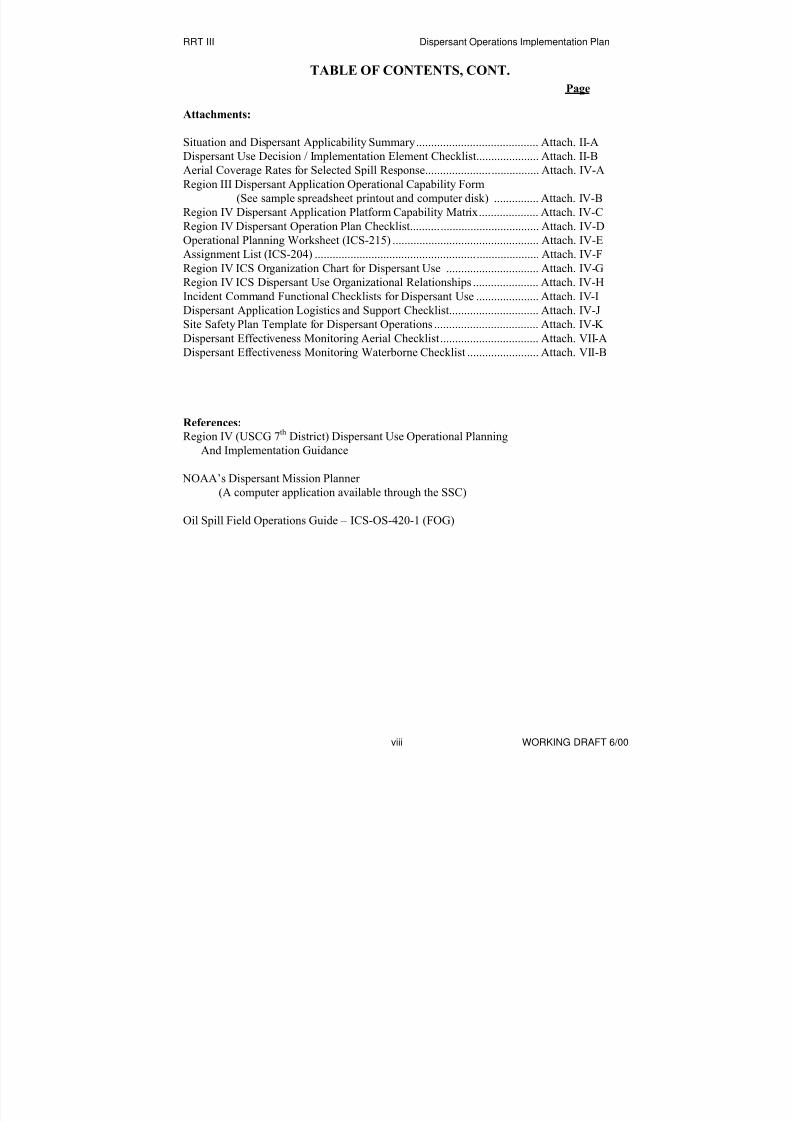
Attachments:
Situation and Dispersant Applicability Summary......................................... Attach. II-A
Dispersant Use Decision / Implementation Element Checklist..................... Attach. II-B
Aerial Coverage Rates for Selected Spill Response...................................... Attach. IV-A
Region III Dispersant Application Operational Capability Form
(See sample spreadsheet printout and computer disk) ............... Attach. IV-B
Region IV Dispersant Application Platform Capability Matrix.................... Attach. IV-C
Region IV Dispersant Operation Plan Checklist........................................... Attach. IV-D
Operational Planning Worksheet (ICS-215) ................................................. Attach. IV-E
Assignment List (ICS-204) ........................................................................... Attach. IV-F
Region IV ICS Organization Chart for Dispersant Use ............................... Attach. IV-G
Region IV ICS Dispersant Use Organizational Relationships ...................... Attach. IV-H
Incident Command Functional Checklists for Dispersant Use ..................... Attach. IV-IDispersant Application Logistics and Support Checklist.............................. Attach. IV-J
Site Safety Plan Template for Dispersant Operations ................................... Attach. IV-K
Dispersant Effectiveness Monitoring Aerial Checklist................................. Attach. VII-A
Dispersant Effectiveness Monitoring Waterborne Checklist ........................ Attach. VII-B
References:
Region IV (USCG 7th
District) Dispersant Use Operational Planning
And Implementation Guidance
NOAA’s Dispersant Mission Planner
(A computer application available through the SSC)
Oil Spill Field Operations Guide – ICS-OS-420-1 (FOG)
8/3/2019 Guia de selección de tecnologias aplicadas a derrames Vol II
http://slidepdf.com/reader/full/guia-de-seleccion-de-tecnologias-aplicadas-a-derrames-vol-ii 22/298
RRT III Dispersant Operations Implementation Plan
I-1 WORKING DRAFT 6/00
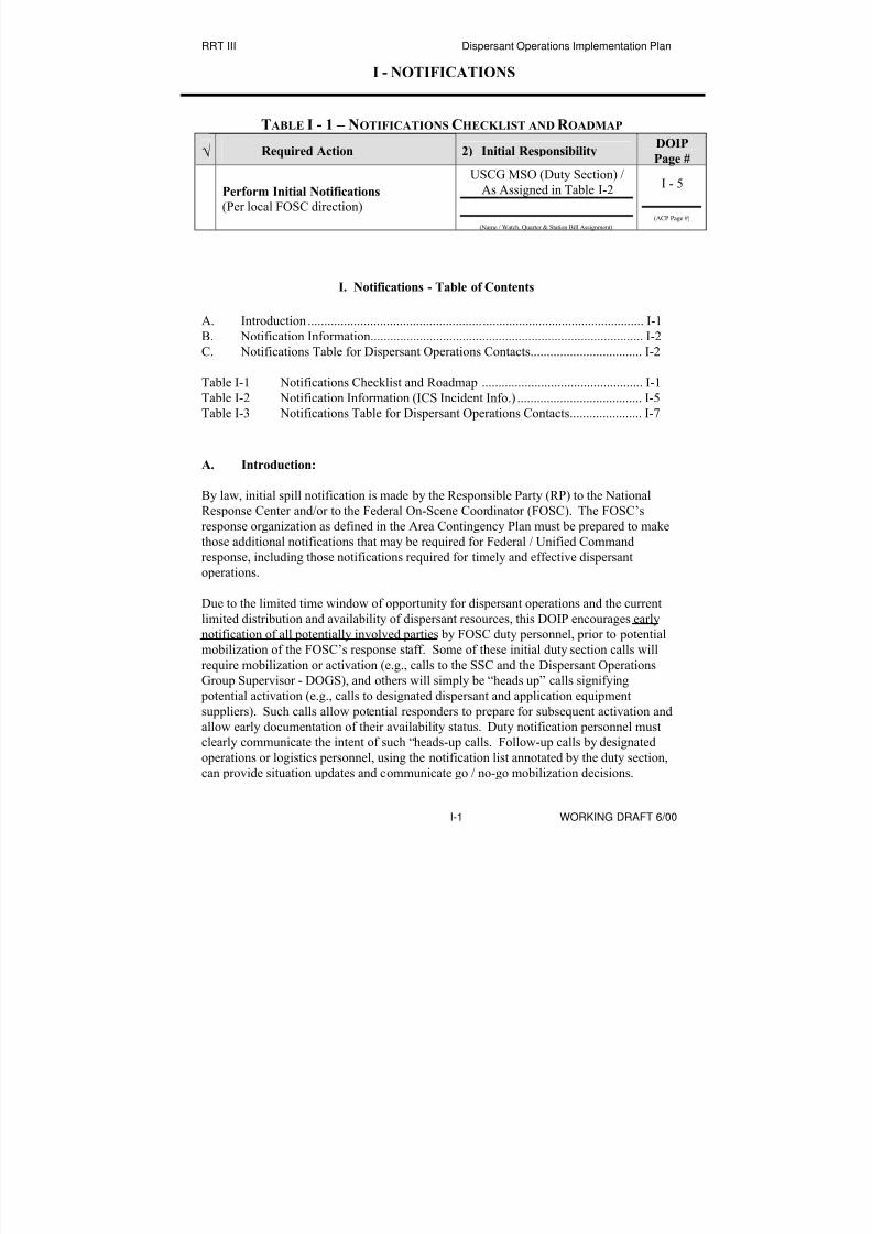
I - NOTIFICATIONS
TABLE I - 1 – NOTIFICATIONS CHECKLIST AND R OADMAP
√ Required Action 2) Initial ResponsibilityDOIP
Page #
Perform Initial Notifications
(Per local FOSC direction)
USCG MSO (Duty Section) /
As Assigned in Table I-2
(Name / Watch, Quarter & Station Bill Assignment)
I - 5
(ACP Page #)
I. Notifications - Table of Contents
A. Introduction ...................................................................................................... I-1
B. Notification Information................................................................................... I-2C. Notifications Table for Dispersant Operations Contacts.................................. I-2
Table I-1 Notifications Checklist and Roadmap ................................................. I-1
Table I-2 Notification Information (ICS Incident Info.) ...................................... I-5
Table I-3 Notifications Table for Dispersant Operations Contacts...................... I-7
A. Introduction:
By law, initial spill notification is made by the Responsible Party (RP) to the NationalResponse Center and/or to the Federal On-Scene Coordinator (FOSC). The FOSC’s
response organization as defined in the Area Contingency Plan must be prepared to make
those additional notifications that may be required for Federal / Unified Command
response, including those notifications required for timely and effective dispersant
operations.
Due to the limited time window of opportunity for dispersant operations and the current
limited distribution and availability of dispersant resources, this DOIP encourages early
notification of all potentially involved parties by FOSC duty personnel, prior to potential
mobilization of the FOSC’s response staff. Some of these initial duty section calls will
require mobilization or activation (e.g., calls to the SSC and the Dispersant OperationsGroup Supervisor - DOGS), and others will simply be “heads up” calls signifying
potential activation (e.g., calls to designated dispersant and application equipment
suppliers). Such calls allow potential responders to prepare for subsequent activation and
allow early documentation of their availability status. Duty notification personnel must
clearly communicate the intent of such “heads-up calls. Follow-up calls by designated
operations or logistics personnel, using the notification list annotated by the duty section,
can provide situation updates and communicate go / no-go mobilization decisions.

8/3/2019 Guia de selección de tecnologias aplicadas a derrames Vol II
http://slidepdf.com/reader/full/guia-de-seleccion-de-tecnologias-aplicadas-a-derrames-vol-ii 23/298
RRT III Dispersant Operations Implementation Plan
I-2 WORKING DRAFT 6/00
Area Committees and/or FOSC staffs are encouraged to customize the DOIP notification
list with respect to which calls are required and which are “heads up” calls, and to
indicate who is responsible for which notifications and follow-up actions. Also area/local
resources must be added to the basic list provided and perhaps some contacts deleted.
The lists of commercial dispersant equipment and service providers indicated herein is
intended as a sample or point of departure for further FOSC/Area Committee planning
and preparation. Some of the resources listed may no longer be available, and for othersthere may be limitations on their availability for contractual, logistic, or other reasons.
Mobilization requirements (including contractual, funding, and logistics issues) for all
key dispersant resources to be listed in an ACP should be thoroughly investigated and
resolved prior to inclusion in the ACP.
B. Notification Information:
Each FOSC and Area Committee should address the initial flow of information
concerning the spill event and provide guidance on its documentation. The National
Response Center will document and forward initial information called in by theResponsible Party (RP). The FOSC’s duty section (or other individual receiving the call)
should be prepared to document information received directly from the RP and may
prompt the RP to provide as much additional key information as might be available at this
early time in the spill event. Each RP/Plan Holder must have an initial notification form
in its response plan but information documented will vary widely. The FOSC’s response
organization is encouraged to document incoming information on the (USCG/NOAA)
ICS Incident Notification form (“Incident Info. 8/96”, Table I-2 below). Most of the
information to be documented on this form will not be available upon initial notification,
but as a living document, it provides a good tool for seeking out and recording additional
key information as it becomes available. When established, the Situation Unit in the
Planning Section will inherit the Incident Information form from the duty section and willcontinue to update it with current information which can then be provided by status
board, or electronic transfer throughout the response organization. The Incident
Information form can be attached to other working documents requiring contained data to
minimize data entry requirements on additional forms.
C. Notifications Table for Dispersant Operations Contacts (Table 1-3 below):
Purpose: To provide the earliest possible notification of all personnel/parties who could
potentially be involved in dispersant operations; to document all calls made (date/time,
caller, action initiated); and to provide a complete contacts list for possible follow-up
calls.
Preparation: During a response, this table is to be filled out by the FOSC’s duty section,
or by other personnel as locally assigned and indicated herein. In the planning process,
the Dispersant Operations Group Supervisor (or other FOSC designee) should customize
the notification form as noted above. Designated callers must be instructed with respect
to proper notification procedures, including what to say and what not to say, particularly

8/3/2019 Guia de selección de tecnologias aplicadas a derrames Vol II
http://slidepdf.com/reader/full/guia-de-seleccion-de-tecnologias-aplicadas-a-derrames-vol-ii 24/298
RRT III Dispersant Operations Implementation Plan
I-3 WORKING DRAFT 6/00
to prospective contractors. The F&A Section Chief should assist in the designation and
training of personnel authorized to activate contractors.
Distribution: During a response, the FOSC duty section, or other assigned callers should
make copies of this form documenting initial calls made and provide copies to the SSC,
the Dispersant Operations Group Supervisor (DOGS) and other designated follow-up
callers. Copies of completed forms from all callers should be forwarded to theDocumentation Unit Leader in the Planning Section.
Instructions: During a response, designated callers make assigned notifications and
document date, time, and result (individual contacted, available, mobilized, ETA) in the
spaces provided. This form should be initially customized for each ACP and points of
contact and phone numbers validated or updated at least annually.

8/3/2019 Guia de selección de tecnologias aplicadas a derrames Vol II
http://slidepdf.com/reader/full/guia-de-seleccion-de-tecnologias-aplicadas-a-derrames-vol-ii 25/298
RRT III Dispersant Operations Implementation Plan
I-4 WORKING DRAFT 6/00
This Page Intentionally Left Blank

8/3/2019 Guia de selección de tecnologias aplicadas a derrames Vol II
http://slidepdf.com/reader/full/guia-de-seleccion-de-tecnologias-aplicadas-a-derrames-vol-ii 26/298
RRT III Dispersant Operations Implementation Plan
I-5 WORKING DRAFT 6/00
INCIDENT STATUS
INCIDENT INFORMATION
VESSEL/FACILITY INFORMATION AND PO INTS OF CONTACT
Notificatio n Info. 8/96
INCIDENT INFORMATIONIncident Name Information as of :
06/24/1998 16 18Date Time
NAME OF PERSON REPORTING THE INCIDENT :
Call Back Number(s) of person reporting the inci dent :
Vessel / Facility Name:Location:
Type of Vessel / Facility:
Contact / Agent:
Owner:
Operator / Charterer:
Number of people onboard / on-site:
Phone:
Phone:
Phone:
VESSEL SPECIFIC INFORMATION
Last Port of Call:
Particulars: Length: Ft.
Type of Hull:
Hull Material:
Type of Propulsion:
Petroleum Pr oducts Onboard:
Type of Cargo:
Total Quantity:
Type of Fuel:
ENVIRONMENTAL INFORMATION
Tonnage (Gross/Net/DWT): Draft Fwd: Aft: Year Built:
Flag:Destination:
Barrels
Barrels
Total Capacity:
Quantity on Board:
Total Number of Tanks on Vessel :
GallonsBarrels x 4 2=
Location:
Type of Casualty:
Number of Tanks Impacted:
Material(s) Spilled:
Estimated Quantity Spilled:
Source Secured?:
Notes:
Lat/Long:
Total Capacity of Affected Tanks:
Viscosity:
Classification:
If Not, Estimated Spill Rate:
Injuries/Casualties:
Vessel Status:
Set and Drift: Es timated Time to Dock/Anchor: Estimated Time of Arrival:
Approximate Size of Hole:
Degrees:
06 /24/1 99 8 16:1 8:0 1Date/Time Prepared:Prepared By:
Wind Speed:
Wave H eight:
Current:
Swell Height:
Wind Direction:
Wave D irection:
Current Direction:
Swell D irection:
Air Temperature:
Conditions:
Water Temperature:
Tide:
High Tide at:
Low Tide at:
Hours
Hours
°F°FKnots
Feet
Knots
Feet
SAR Underway?
Vessel holed?
List? Trim?
Vessel on fire? Fire assistance:
Flooding assistance:Vessel flooding?

8/3/2019 Guia de selección de tecnologias aplicadas a derrames Vol II
http://slidepdf.com/reader/full/guia-de-seleccion-de-tecnologias-aplicadas-a-derrames-vol-ii 27/298
RRT III Dispersant Ope
I-6 WORKING DRAFT 6/00
This Page Intentionally Left Blank

8/3/2019 Guia de selección de tecnologias aplicadas a derrames Vol II
http://slidepdf.com/reader/full/guia-de-seleccion-de-tecnologias-aplicadas-a-derrames-vol-ii 28/298
RRT III Dispersant
I-7
TABLE I-3
NOTIFICATIONS
Note: The following notifications are specific to dispersant operations. It is assumed that other members of the r
via an existing notifications list – e.g. FOSC, General Staff, Command Staff, EPA, resource trustees, etc.
Date/Time
Last Updated Name Signature
IMMEDIATE ACTION: These personnel will be immediately activated / mobilized to carry out assigned respons
Notification Responsibilities: One DOGS and one NOAA representative will be immediately notified by the Duty
Date/Time
Notified
Avail-
able?
Date/Time
Mobilized
ETA
Date/Time
Position /
Responder
Category Name
Contact
Numbers
Caller initials (Y / N)
Dispersant
Operations
Group
Supervisor
Office:
Home:
Hotel:
Cell:
Pgr:
Caller initials (Y / N)
Alternate DOGS
Office:
Home:
Hotel:
Cell:
Pgr:
Caller initials (Y / N)
NOAA SSC
(VA,MD,NC) Gary Ott
Office: 757-898-2320
Home:
Hotel:Cell:
Pgr:
U
H
Y
E
NOAA Hazmat
Alternate SSC
Cdr. Jim Morris
Office: 206-526-6949
Home:
Hotel:
Cell:
Pgr:
N
7
S
E
h

8/3/2019 Guia de selección de tecnologias aplicadas a derrames Vol II
http://slidepdf.com/reader/full/guia-de-seleccion-de-tecnologias-aplicadas-a-derrames-vol-ii 29/298
RRT III Dispersant
I-8
TABLE 1-3. NOTIFICATIONS, CONT.
IMMEDIATE ACTION (cont.):
Notification Responsibilities: The following will be immediately notified by the Duty Section and advise
provided when initial dispersant use decisions are made by the RP, FOSC, SSC, and DOGS.
Date/Time
Notified
Avail-
able?
Date/Time
Mobilized
ETA
Date/Time
Position /Responder
Category Name
Contact
Numbers
Caller initials (Y / N)
Monitoring
Team Leader
Office:
Home:
Hotel:
Cell:
Pgr:
Caller initials (Y / N)
Alternate
Monitoring
Team Leader
Office:
Home:
Hotel:
Cell:
Pgr:
Caller initials (Y / N)
Observers
Coordinator
Office:
Home:
Hotel:
Cell:
Pgr:
Caller initials (Y / N)
Alternate
Observers
Coordinator
Office:
Home:
Hotel:
Cell:
Pgr:
Caller initials (Y / N)
Office:
Home:
Hotel:
Cell:
Pgr:
Caller initials (Y / N)
Office:
Home:
Hotel:
Cell:
Pgr:

8/3/2019 Guia de selección de tecnologias aplicadas a derrames Vol II
http://slidepdf.com/reader/full/guia-de-seleccion-de-tecnologias-aplicadas-a-derrames-vol-ii 30/298
RRT III Dispersant
I-9
TABLE 1-3. NOTIFICATIONS, CONT.
DISPERSANT APPROVAL CONTACTS:
Notification Responsibilities: The following will be initially notified of the spill by:_____________________________.
Date/Time
Notified
Avail-
able?
Date/Time
Mobilized
ETA
Date/Time
Position /
Responder
Category Name
Contact
Numbers
Caller initials (Y / N)
EPA
Office:Home:
Hotel:
Cell:
Pgr:
Caller initials (Y / N)
USCG
Office:
Home:
Hotel:
Cell:
Pgr:
Caller initials (Y / N)
DOI
Office:
Home:
Hotel:
Cell:
Pgr:
NOTE: Notify potentially affected states only.
Caller initials (Y / N)
Delaware
Office:
Home:
Cell:
Pgr:
Caller initials (Y / N)
Maryland
Office:
Home:
Cell:
Pgr:
Caller initials (Y / N)
Pennsylvania
Office:
Hotel:
Cell:
Pgr:
Caller initials (Y / N)
Virginia
Office:
Hotel:
Cell:
Pgr:
Caller initials (Y / N)
West
Virginia
Office:
Home:
Cell:
Pgr:

8/3/2019 Guia de selección de tecnologias aplicadas a derrames Vol II
http://slidepdf.com/reader/full/guia-de-seleccion-de-tecnologias-aplicadas-a-derrames-vol-ii 31/298
RRT III Dispersant
I-10
TABLE 1-3. NOTIFICATIONS, CONT.
DISPERSANT APPLICATION AIRCRAFT
Notification Responsibilities: The Duty Section will provide “heads up” notification only, to the following: (The
mobilization or expenditure of funds).
Date/Time
Notified
Avail-
able?
Date/Time
Mobilized
ETA
Date/Time
Contract /
Agreement
Status Name
Contact
Numbers
Caller initials (Y / N)
Airborne
Support, Inc.
Office: 504-851-6391
Home:
Hotel:
Cell:
Pgr:
A
H
Caller initials (Y / N)
Clean
Caribbean
Co-op
Office: 954-983-9880
Home:
Hotel:
Cell:
Pgr:
C
P
Caller initials (Y / N)
Clean Harbors
Co-op
Office: 908-738-3002
Home:
Hotel:
Cell:Pgr:
C
E
Caller initials (Y / N)
EADC
Office: 603-770-1813
Home:
Hotel:
Cell:
Pgr:
E
F
M
Caller initials (Y / N)
Southern Air
Transport
Office: 800-327-6456
Home:
Hotel:
Cell:
Pgr:
W
*
p
Caller initials (Y / N)
Office:
Home:
Hotel:Cell:
Pgr:
Caller initials (Y / N)
Office:
Home:
Hotel:
Cell:
Pgr:

8/3/2019 Guia de selección de tecnologias aplicadas a derrames Vol II
http://slidepdf.com/reader/full/guia-de-seleccion-de-tecnologias-aplicadas-a-derrames-vol-ii 32/298
RRT III Dispersant
I-11
TABLE 1-3. NOTIFICATIONS, CONT.
DISPERSANT APPLICATION VESSELS
Notification Responsibilities: The Duty Section will provide “heads up” notification only, to the followin
authorize mobilization or expenditure of funds).
Date/Time
Notified
Avail-
able?
Date/Time
Mobilized
ETA
Date/Time
Contract /
Agreement
Status Name
Contact
Numbers
Caller initials (Y / N)
Office:
Home:
Hotel:
Cell:
Pgr:
Caller initials (Y / N)
Office:
Home:
Hotel:
Cell:
Pgr:
Caller initials (Y / N)
Office:
Home:
Hotel:
Cell:Pgr:
Caller initials (Y / N)
Office:
Home:
Hotel:
Cell:
Pgr:
Caller initials (Y / N)
Office:
Home:
Hotel:
Cell:
Pgr:
Caller initials (Y / N)
Office:
Home:
Hotel:Cell:
Pgr:
Caller initials (Y / N)
Office:
Home:
Hotel:
Cell:
Pgr:

8/3/2019 Guia de selección de tecnologias aplicadas a derrames Vol II
http://slidepdf.com/reader/full/guia-de-seleccion-de-tecnologias-aplicadas-a-derrames-vol-ii 33/298
RRT III Dispersant
I-12
TABLE 1-3. NOTIFICATIONS, CONT.
VESSEL OF OPPORTUNITY DISPERSANT SYSTEMS (VODS) (Transportable systems
Mobilization of suitable vessels to be coordinated by Logistics Section.):Notification Responsibilities: The Duty Section will provide “heads up” notification only, to the followin
authorize mobilization or expenditure of funds).
Date/Time
Notified
Avail-
able?
Date/Time
Mobilized
ETA
Date/Time
Contract /
AgreementStatus Name
ContactNumbers
Caller initials (Y / N)
Clean Harbors
Co-op
Office: 908-738-3002
Home:
Hotel:
Cell:
Pgr:
C
E
Caller initials (Y / N)
Delaware Bay
& River Co-op
Office: 302-645-7861
Home:
Hotel:
Cell:
Pgr:
D
S
Caller initials (Y / N)
.
Office:Home:
Hotel:
Cell:
Pgr:
Caller initials (Y / N)
Office:
Home:
Hotel:
Cell:
Pgr:
Caller initials (Y / N)
Office:
Home:
Hotel:
Cell:
Pgr:
Caller initials (Y / N)
Office:
Home:
Hotel:
Cell:
Pgr:

8/3/2019 Guia de selección de tecnologias aplicadas a derrames Vol II
http://slidepdf.com/reader/full/guia-de-seleccion-de-tecnologias-aplicadas-a-derrames-vol-ii 34/298
RRT III Dispersant
I-13
TABLE 1-3. NOTIFICATIONS, CONT.
SPOTTER AIRCRAFT (For directing application aircraft and/or vessel. The same aircraft may be li
observer aircraft lists. This list may be shared with the Logistics Section to designate and mobilize aircraft
Notification Responsibilities: The Duty Section will provide “heads up” notification only, to the followin
authorize mobilization or expenditure of funds).
Date/Time
Notified
Avail-
able?
Date/Time
Mobilized
ETA
Date/Time
Contract /
AgreementStatus Name
ContactNumbers
Caller initials (Y / N)
EADC
Office: 603-770-1813
Home:
Hotel:
Cell:
Pgr:
E
F
M
Caller initials (Y / N)
Airborne
Support, Inc.
Office: 504-851-6391
Home:
Hotel:
Cell:
Pgr:
A
H
Caller initials (Y / N)
Office:Home:
Hotel:
Cell:
Pgr:
Caller initials (Y / N)
Office:
Home:
Hotel:
Cell:
Pgr:
Caller initials (Y / N)
Office:
Home:
Hotel:
Cell:
Pgr:
Caller initials (Y / N)
Office:
Home:
Hotel:
Cell:
Pgr:

8/3/2019 Guia de selección de tecnologias aplicadas a derrames Vol II
http://slidepdf.com/reader/full/guia-de-seleccion-de-tecnologias-aplicadas-a-derrames-vol-ii 35/298
RRT III Dispersant
I-14
TABLE 1-3. NOTIFICATIONS, CONT.
MONITORING AIRCRAFT (To support the dispersant monitoring team):Notification Responsibilities: The Duty Section will provide “heads up” notification only, to the followin
authorize mobilization or expenditure of funds).
Date/TimeNotified
Avail-able?
Date/TimeMobilized
ETADate/Time
Contract /
AgreementStatus Name
ContactNumbers
Caller initials (Y / N)
EADC
Office: 603-770-1813
Home:
Hotel:
Cell:
Pgr:
E
F
M
Caller initials (Y / N)
Airborne
Support, Inc.
Office: 504-851-6391
Home:
Hotel:
Cell:
Pgr:
A
H
Caller initials (Y / N)
Office:
Home:
Hotel:
Cell:
Pgr:
Caller initials (Y / N)
Office:
Home:
Hotel:
Cell:
Pgr:
Caller initials (Y / N)
Office:
Home:
Hotel:
Cell:Pgr:
Caller initials (Y / N)
Office:
Home:
Hotel:
Cell:
Pgr:

8/3/2019 Guia de selección de tecnologias aplicadas a derrames Vol II
http://slidepdf.com/reader/full/guia-de-seleccion-de-tecnologias-aplicadas-a-derrames-vol-ii 36/298
RRT III Dispersant
I-15
TABLE 1-3. NOTIFICATIONS, CONT.
OBSERVER AIRCRAFT (Assigned to the Observers Coordinator to support resource trustees and o
directly involved in dispersant operations)
Notification Responsibilities: The Duty Section will provide “heads up” notification only, to the followin
authorize mobilization or expenditure of funds).
Date/Time
Notified
Avail-
able?
Date/Time
Mobilized
ETA
Date/Time
Contract /Agreement
Status Name
Contact
Numbers
Caller initials (Y / N)
EADC
Office: 603-770-1813
Home:
Hotel:
Cell:
Pgr:
E
F
M
Caller initials (Y / N)
Airborne
Support, Inc.
Office: 504-851-6391
Home:
Hotel:
Cell:
Pgr:
A
H
Caller initials (Y / N)
Office:
Home:
Hotel:
Cell:
Pgr:
Caller initials (Y / N)
Office:
Home:
Hotel:
Cell:
Pgr:
Caller initials (Y / N)
Office:
Home:
Hotel:
Cell:
Pgr:
Caller initials (Y / N)
Office:
Home:
Hotel:
Cell:
Pgr:

8/3/2019 Guia de selección de tecnologias aplicadas a derrames Vol II
http://slidepdf.com/reader/full/guia-de-seleccion-de-tecnologias-aplicadas-a-derrames-vol-ii 37/298
RRT III Dispersant
I-16
TABLE 1-3. NOTIFICATIONS, CONT.
ADDITIONAL DISPERSANT STOCKS AND EQUIPMENT (Additional dispersant provid
supply organizations, such as dispersant bucket suppliers that do not supply the helicopters to carry them.)
Notification Responsibilities: The Duty Section will provide “heads up” notification only, to the followin
authorize mobilization or expenditure of funds).
Date/Time
Notified
Avail-
able?
Date/Time
Mobilized
ETA
Date/Time
Contract /Agreement
Status Name
Contact
Numbers
Caller initials (Y / N)
Clean
Caribbean
Co-op
Office: 954-983-9880
Home:
Cell:
Pgr:
C
P
Caller initials (Y / N)
Clean Gulf
Assoc.’s
Office: 504-593-6700
Home:
Cell:
Pgr:
C
P
G
H
Caller initials (Y / N)
Clean HarborsCo-op
Office: 908-738-3002
Home:Cell:
Pgr:
CE
Caller initials (Y / N)
Delaware Bay
& River Co-op
Office: 302-645-7861
Home:
Cell:
Pgr:
D
S
Caller initials (Y / N)
USAF
Office: 330-392-1111
Home:
Cell:
Pgr:
U
Y
Caller initials (Y / N)
NRC
Office: 516-369-8644
Home:
Cell:
Pgr:
N
M
Caller initials (Y / N)
Office:
Home:
Cell:
Pgr:

8/3/2019 Guia de selección de tecnologias aplicadas a derrames Vol II
http://slidepdf.com/reader/full/guia-de-seleccion-de-tecnologias-aplicadas-a-derrames-vol-ii 38/298
RRT III Dispersant Operations Implementation Plan
II-1 WORKING DRAFT 6/00
II. DISPERSANT APPLICABILITY
Table II - 1 – Applicability Checklist and Roadmap
√ Required Action Initial ResponsibilityDOIP
Page #
Gather Incident Information
(pertinent to Dispersant Operations)
DOGS / NOAA SSC / Alternate
(Name / Watch, Quarter & Station Bill Assignment)
II -1
(ACP Page #)
Determine Applicability
(Will available dispersant disperse oil and
protect sensitive areas – net environmental
benefit)
DOGS / NOAA SSC / Alternate
(Name / Watch, Quarter & Station Bill Assignment)
II -1
(ACP Page #)
II Applicability - Table of Contents
A. Introduction........................................................................................................................ II-1
B. Gather Incident Information............................................................................................... II-2
C. Determine Dispersant Applicability................................................................................... II-2
Figure II.1 Dispersant Applicability Decision Tree .............................................................. II-3
Table II.1 Applicability Checklist and Roadmap ................................................................ II-1
Table II.2 Definitions........................................................................................................... II-4
Attachments:
A. Situation and Dispersant Applicability Summary............................................ Attach. II-A
B. Dispersant Use Decision / Implementation Element Checklist ....................... Attach. II-B
A. Introduction:
The NOAA SSC or alternate designee will assemble situation data (quantity of oil spilled, oil type, API
Gravity, viscosity, etc.) and make an initial assessment of the dispersability of the spilled oil using tools
identified herein. In this context “dispersant applicability” means, will the dispersant selected/availableeffectively disperse the oil spilled under the present environmental conditions, and is this likely to result in
net environmental benefit. Table II-2 below provides an overview of the applicability assessment. The
tools (attachments) discussed below may also be useful in determining applicability.

8/3/2019 Guia de selección de tecnologias aplicadas a derrames Vol II
http://slidepdf.com/reader/full/guia-de-seleccion-de-tecnologias-aplicadas-a-derrames-vol-ii 39/298
RRT III Dispersant Operations Implementation Plan
II-2 WORKING DRAFT 6/00
B. Gather Incident Information:
Start with the information currently available on the Incident Information Sheet (ICS – Notification Info.
8/96 form, DOIP Table I-2). Seek additional information from appropriate sources to determine
applicability. Attachments IIA and IIB may be useful tools for assembly and assessment of information.
C. Determine Dispersant Applicability
Figure II-1, Table II-2 and attachments IIA and IIB may be useful in determining dispersant applicability.
The Dispersant Operations Group Supervisor (DOGS), NOAA SSC, or alternates assigned to determine
applicability must bear in mind that an early assessment is critical for dispersant application to be
successful.

8/3/2019 Guia de selección de tecnologias aplicadas a derrames Vol II
http://slidepdf.com/reader/full/guia-de-seleccion-de-tecnologias-aplicadas-a-derrames-vol-ii 40/298
RRT III Dispersant Operations Implementation Plan
Figure II-1. Dispersant Applicability decision treeII-3 WORKING DRAFT 6/00
Start Here: (Definitions on next page)
Is oil moving toward shores
or offshore seabird colonies?
Conduct operational
monitoring and begin
effects data gathering, as
appropriate.1
Is oil in re-a roval zone?Are shoreline habitats and
water surface resources at
risk or threatened?
Use other
countermeasure(s)
Complete necessary
process for approval.
Simultaneously,
initiate dispersant
operations planning.
Use other
countermeasure(s)
Is the oil dispersible?2
Use other
countermeasure(s)
Implement dispersant
operations planning and
notifications according
to dispersant pre-
approval policy.
NO
NO
YES
YES
NOYES
YES
NO
YES NO
AND
Consider case-by-
case approval
Is the chemical
dispersant listed on the
NCP Product Schedule?NO
YES
Is the chemical
dispersant listed on the
NCP Product Schedule?
YES
Is the oil dis ersible?2
NO
Oil Spill
Occurred

8/3/2019 Guia de selección de tecnologias aplicadas a derrames Vol II
http://slidepdf.com/reader/full/guia-de-seleccion-de-tecnologias-aplicadas-a-derrames-vol-ii 41/298
RRT III Dispersant Operations Implementation Plan
II-4 WORKING DRAFT 6/00
Table II-2 “Definitions”
#1 Operational Monitoring (a.k.a. effectiveness monitoring) is defined by Pond et al., (1997) as
monitoring that “provides qualitative information, through visual observations [or other specified
method] by trained personnel in real-time, during the actual response, to influence operationaldecision-making.”
Effects monitoring (a.k.a. long-term data gathering) is defined as data that “provides quantitative
information on the use of [a product] and the real effects following a spill to influence planning and
future research” (Pond et al., 1997). The longer time (weeks, or even months) involved with
obtaining results from effects monitoring dictates that sampling should not be used to influence
incident-specific decision-making. However, response and trustee agencies should begin gathering
effects monitoring data as soon as practicable. Effects monitoring information collection is a long-
term process and the results are typically not available in real-time to affect decision-making.
During a response, operational personnel need to be able to ensure the success of a response
technique, and in particular, be able to direct, redirect, or discontinue the use of the responsetechnique. Operational monitoring could be as simple as visually monitoring the effectiveness of a
particular boom. Is it placed correctly? Is it functioning as expected? Is there any oil remaining to
be captured with the particular boom? Or as complete as using Tier 3 Special Monitoring of
Applied Response Technologies (SMART) protocols for dispersant use or in situ burn monitoring.

8/3/2019 Guia de selección de tecnologias aplicadas a derrames Vol II
http://slidepdf.com/reader/full/guia-de-seleccion-de-tecnologias-aplicadas-a-derrames-vol-ii 42/298
RRT III Dispersant Operations Implementation Plan
III-1 WORKING DRAFT 6/00
III. DISPERSANT USE APPROVAL
Table III - 1 – Approval Checklist and Roadmap
√ Required Action Initial ResponsibilityDOIP
Page #
Determine Pre-Approval Status
(For proposed application areas)
NOAA SSC / Alternate
(Name / Watch, Quarter & Station Bill Assignment)
III -
(ACP Page #)
Advise FOSC
(Pre-approved or need for application)
NOAA SSC / Alternate
(Name / Watch, Quarter & Station Bill Assignment)
III -
(ACP Page #)
Coordinate with EPA & Trustees
(Advise of FOSC intention to disperse or
request approval for non-pre-approved
areas)
NOAA SSC / Alternate
(Name / Watch, Quarter & Station Bill Assignment)
III -
(ACP Page #)
Initiate Application for Approval
(As required)
NOAA SSC / Alternate
(Name / Watch, Quarter & Station Bill Assignment)
III -
(ACP Page #)
Approve Dispersant Use
(Per applicable guidelines)
FOSC
(Name / Watch, Quarter & Station Bill Assignment)
III -
(ACP Page #)
Note: The above steps are provided as general guidelines. The dispersant use approval
process and areas of pre-approval for Region III are presented in the Region III Regional Contingency Plan
(RCP). This draft of the DOIP does not include a duplication or synopsis of this RCP information. If such
an addition is determined to be useful, one will be developed at a later date

8/3/2019 Guia de selección de tecnologias aplicadas a derrames Vol II
http://slidepdf.com/reader/full/guia-de-seleccion-de-tecnologias-aplicadas-a-derrames-vol-ii 43/298
RRT III Dispersant Operations Implementation Plan
III-2 WORKING DRAFT 6/00
This Page Intentionally Left Blank
.
8/3/2019 Guia de selección de tecnologias aplicadas a derrames Vol II
http://slidepdf.com/reader/full/guia-de-seleccion-de-tecnologias-aplicadas-a-derrames-vol-ii 44/298
RRT III Dispersant Operations Implementation Plan
WORKING DRAFT 6/00IV-1
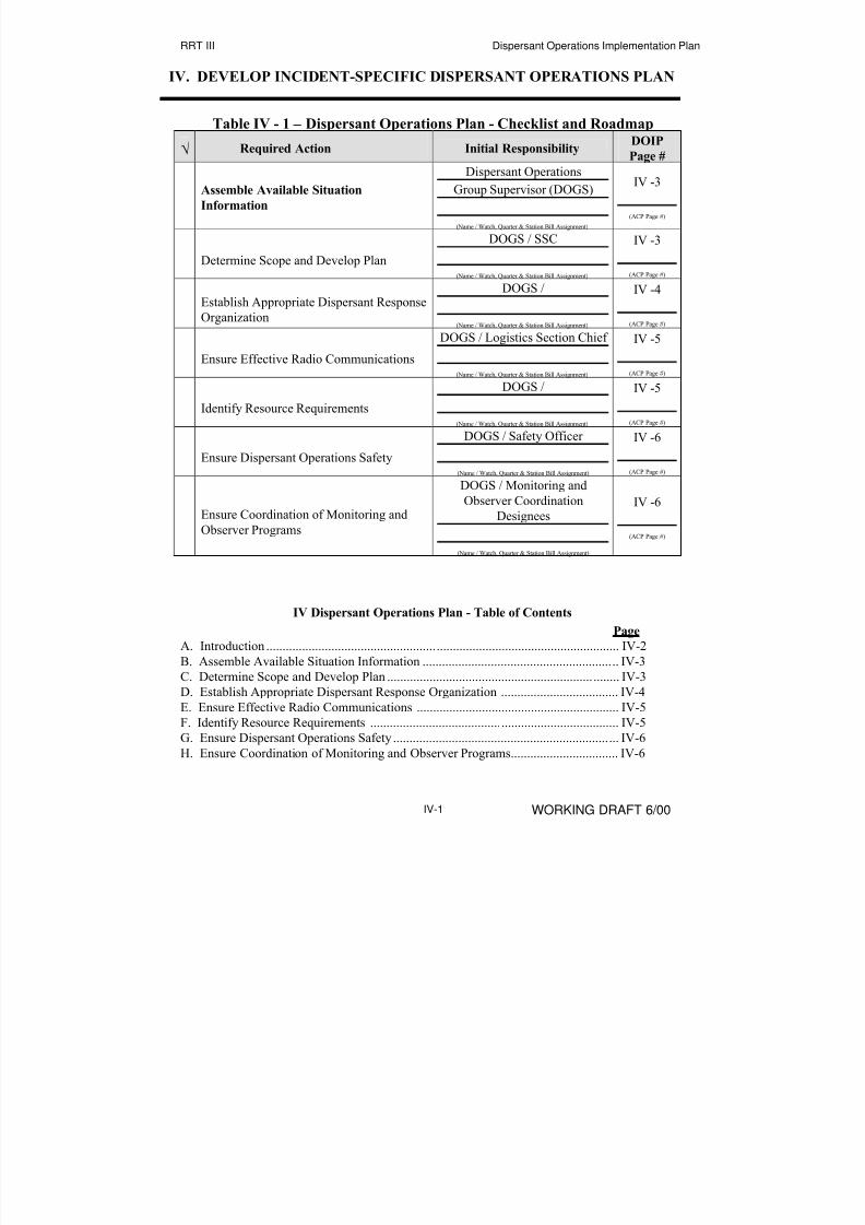
IV. DEVELOP INCIDENT-SPECIFIC DISPERSANT OPERATIONS PLAN
Table IV - 1 – Dispersant Operations Plan - Checklist and Roadmap
√ Required Action Initial ResponsibilityDOIP
Page #
Assemble Available Situation
Information
Dispersant Operations
Group Supervisor (DOGS)
(Name / Watch, Quarter & Station Bill Assignment)
IV -3
(ACP Page #)
Determine Scope and Develop Plan
DOGS / SSC
(Name / Watch, Quarter & Station Bill Assignment)
IV -3
(ACP Page #)
Establish Appropriate Dispersant Response
Organization
DOGS /
(Name / Watch, Quarter & Station Bill Assignment)
IV -4
(ACP Page #)
Ensure Effective Radio Communications
DOGS / Logistics Section Chief
(Name / Watch, Quarter & Station Bill Assignment)
IV -5
(ACP Page #)
Identify Resource Requirements
DOGS /
(Name / Watch, Quarter & Station Bill Assignment)
IV -5
(ACP Page #)
Ensure Dispersant Operations Safety
DOGS / Safety Officer
(Name / Watch, Quarter & Station Bill Assignment)
IV -6
(ACP Page #)
Ensure Coordination of Monitoring and
Observer Programs
DOGS / Monitoring and
Observer Coordination
Designees
(Name / Watch, Quarter & Station Bill Assignment)
IV -6
(ACP Page #)
IV Dispersant Operations Plan - Table of Contents
Page
A. Introduction ............................................................................................................ IV-2
B. Assemble Available Situation Information ............................................................ IV-3C. Determine Scope and Develop Plan ....................................................................... IV-3
D. Establish Appropriate Dispersant Response Organization .................................... IV-4
E. Ensure Effective Radio Communications .............................................................. IV-5
F. Identify Resource Requirements ............................................................................ IV-5
G. Ensure Dispersant Operations Safety ..................................................................... IV-6
H. Ensure Coordination of Monitoring and Observer Programs................................. IV-6
8/3/2019 Guia de selección de tecnologias aplicadas a derrames Vol II
http://slidepdf.com/reader/full/guia-de-seleccion-de-tecnologias-aplicadas-a-derrames-vol-ii 45/298
RRT III Dispersant Operations Implementation Plan
WORKING DRAFT 6/00IV-2
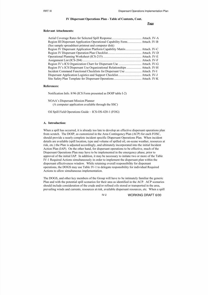
IV Dispersant Operations Plan - Table of Contents, Cont.
Page
Relevant Attachments:
Aerial Coverage Rates for Selected Spill Response...................................... Attach. IV-A
Region III Dispersant Application Operational Capability Form.................. Attach. IV-B
(See sample spreadsheet printout and computer disk)
Region IV Dispersant Application Platform Capability Matrix.................... Attach. IV-C
Region IV Dispersant Operation Plan Checklist........................................... Attach. IV-D
Operational Planning Worksheet (ICS-215) ................................................. Attach. IV-E
Assignment List (ICS-204) ........................................................................... Attach. IV-F
Region IV’s ICS Organization Chart for Dispersant Use ............................. Attach. IV-G
Region IV’s ICS Dispersant Use Organizational Relationships ................... Attach. IV-H
Incident Command Functional Checklists for Dispersant Use ..................... Attach. IV-I
Dispersant Application Logistics and Support Checklist.............................. Attach. IV-J
Site Safety Plan Template for Dispersant Operations ................................... Attach. IV-K
References:
Notification Info. 8/96 (ICS Form presented as DOIP table I-2)
NOAA’s Dispersant Mission Planner
(A computer application available through the SSC)
Oil Spill Field Operations Guide – ICS-OS-420-1 (FOG)
A. Introduction:
When a spill has occurred, it is already too late to develop an effective dispersant operations plan
from scratch. The DOIP, as customized in the Area Contingency Plan (ACP) for each FOSC,
should provide a nearly complete incident specific Dispersant Operations Plan. When incident
details are available (spill location, type and volume of spilled oil, on-scene weather, resources at
risk, etc.) the Plan is adjusted accordingly, and ultimately incorporated into the initial Incident
Action Plan (IAP). On the other hand, for dispersant operations to be effective, much of the
Dispersant Operations Plan may have to be implemented in the emergency phase, prior to
approval of the initial IAP. In addition, it may be necessary to initiate two or more of the Table
IV-1 Required Actions simultaneously in order to implement the dispersant plan within thedispersant effectiveness window. While retaining overall responsibility for dispersant
operations, the DOGS may use Table IV-1 to delegate responsibility for individual Required
Actions to allow simultaneous implementation.
The DOGS, and other key members of the Group will have to be intimately familiar the generic
Plan and with the potential spill scenarios for their area as identified in the ACP. ACP scenarios
should include consideration of the crude and/or refined oils stored or transported in the area,
prevailing winds and currents, resources at risk, available dispersant resources, etc. When a spill

8/3/2019 Guia de selección de tecnologias aplicadas a derrames Vol II
http://slidepdf.com/reader/full/guia-de-seleccion-de-tecnologias-aplicadas-a-derrames-vol-ii 46/298
RRT III Dispersant Operations Implementation Plan
WORKING DRAFT 6/00IV-3
occurs and the decision to apply dispersants has been made, key Dispersant Operations Group
personnel, relying on their knowledge of the generic Plan will be prepared to immediately
implement assigned roles and responsibilities. Because key members of the Group, specifically
Plan Holder personnel and the suppliers of dispersant, application equipment, spotter aircraft, etc.
are not members of the FOSC’s staff, Tabletop and Equipment Deployment exercises involving
the whole Group will be critical to the success of actual dispersant operations. Federal and state
dispersant use decision-makers (EPA, DOI, DOC, and potentially affected states) must also beinvolved in all Tabletops and Equipment Deployment Exercises to identify and resolve potential
problems in the approval process. These decision-makers must also be familiar and comfortable
with the entire Dispersant Operations Implementation Plan (specifically applicability and
approval - sections II and III).
B. Assemble Available Situation Information:
Early and continuing communication between the Dispersant Operations Group Supervisor
(DOGS), the NOAA SSC (or designated alternate), and the FOSC’s duty section (and later the
Situation Unit of the Planning Section) should ensure that all parties are implementing assigned
responsibilities with the benefit of the most current information. It will generally be desirable for
the DOGS and the SSC to proceed to the Incident Command Post as early as possible for ready
access to current information. In any event, it is recommended that the ICS Form – “Notification
Info. 8/96”, (DOIP Table I-1), be used to document and communicate incident information, at
least early in the response. This form may be posted and updated by Situation Unit personnel, or
it may be maintained electronically on a local area network (LAN) or it may be printed out and
faxed (with date/time indicated) to remote units. How this and other response information is
maintained and communicated is a critical issue to be resolved at the Area level and is beyond
the scope of this DOIP.
C. Determine Scope and Develop Plan:
When available incident information has been assembled, the DOGS, in coordination with the
SSC, the FOSC, and/or other designated personnel will estimate the spill volume and slick
area to be dispersed. (This may not be the entire volume or area of oil spilled). This estimate
will be a subjective evaluation based on the total volume spilled, projected total area of the slick,
weather, other response countermeasures to be employed (mechanical recovery and in-situ
burning), trajectory and overflight information, resources at risk, and projected net environmental
benefit of dispersant application. The ICS Notification Information form is a useful starting
point for approaching this evaluation.
When the volume of oil and the anticipated area of the slick to be dispersed have been
determined, the DOGS will determine the quantity of dispersant required and the most
appropriate numbers and types of dispersant platforms (i.e. large or small fixed wing
aircraft, vessels, or helicopters) to be employed. Orders of magnitude rather than precise
numbers should be considered in this analysis. Information with respect to the volume of oil
spilled and the area of the slick, as well as other variables may be difficult to determine early in
the response and estimates will likely change many times in the early hours and even days of the
8/3/2019 Guia de selección de tecnologias aplicadas a derrames Vol II
http://slidepdf.com/reader/full/guia-de-seleccion-de-tecnologias-aplicadas-a-derrames-vol-ii 47/298
RRT III Dispersant Operations Implementation Plan
WORKING DRAFT 6/00IV-4
response. For very large spills, large fixed wing aircraft are indicated, but this does not preclude
initiating dispersant operations with locally or regionally available vessel, helicopter, or small
fixed wing aircraft systems pending the arrival of the larger aircraft system(s).
Early involvement of all members of the dispersant operations group, including contracted
dispersant and service providers, in the pre-incident and incident-specific planning process is
critical to successful operations.
The following attachments (repeated here from page IV-1) may be useful tools for determining
requirements and detailed dispersant mission planning:
Aerial Coverage Rates for Selected Spill Response...........................................Attach IV-A
Region III Dispersant Application Operational Capability Form.......................Attach IV-B
(See sample spreadsheet printout and computer disk)
Region IV Dispersant Application Platform Capability Decision Matrix..........Attach IV-C
Region IV Dispersant Operation Plan Checklist................................................Attach IV-D
Operational Planning Worksheet (ICS-215) ......................................................Attach IV-E
Assignment List (ICS-204) ................................................................................Attach IV-F
D. Develop Appropriate Organization:
Region IV’s “ICS Organization Chart for Dispersant Use” (Attachment IV-G) indicates the
recommended addition of a Dispersant Operations Group to the standard Incident Command
System (ICS) for oil spill response (as presented in the Oil Spill Field Operations Guide – ICS-
OS-420-1 (FOG). This DOIP has referred to a Dispersant Operations Group Supervisor (DOGS)
throughout, and assumes the recommended organization in discussions of monitoring and
observer coordination. The recommended organization is based on previous Region IV Regional
Response Team (RRT-IV) work. It differs from the organizational guidance suggested in the
draft “Special Monitoring of Advanced Response Technologies (SMART)” document. SMART
suggests a “Monitoring Group” but has not addressed the broader issue of a dispersant
organization under the Operations Section. Further refinement of the Region IV Dispersant
Operations Group organization may be required but should be based on lessons learned in
FOSC/Area Tabletop and Equipment Deployment exercises.
Region IV’s “ICS Dispersant Use Organizational Relationships” (Attachment IV-H) indicates the
relationships of the recommended Dispersant Operations Group with other elements of a
standard ICS organization for oil spills. It is suggested that the customized DOIP in the ACP
assign primary and one or more alternate personnel to fill all positions identified in theDispersant Operations Group. This assignment can be documented and contact information
provided in the DOIP Table I-1 Notifications. The FOSC and the DOGS must be prepared to
respond with a fully activated ICS organization, but ICS also allows mobilization of a simplified
organization for minor incidents by filling only required positions. In any event, the FOSC and
the Area Committee should pre-establish an ICS response organization appropriate for a worst-
case incident involving dispersant operations in their area. Primary and one or more alternate
personnel for each position should receive appropriate knowledge and skills training, and
periodic tabletop and equipment deployment drills should be held.

8/3/2019 Guia de selección de tecnologias aplicadas a derrames Vol II
http://slidepdf.com/reader/full/guia-de-seleccion-de-tecnologias-aplicadas-a-derrames-vol-ii 48/298
RRT III Dispersant Operations Implementation Plan
WORKING DRAFT 6/00IV-5
Region IV’s “Incident Command Functional Checklists for Dispersant Use”, attachment IV-I,
may be considered in developing roles and responsibilities for assigned positions.
E. Ensure Effective Radio Communications
The DOGS must coordinate with contracted dispersant resources (Application, spotter,monitoring, and observer aircraft and vessels), with the Communications Unit in the Logistics
Section, and with the Air Operations Branch (if activated), to ensure an effective
communications plan and adequate communications equipment with compatible frequencies.
These communications issues are complex and should be addressed by qualified personnel on the
FOSC’s staff and on the Area Planning Committee during the Area Planning process.
Equipment Deployment Exercises should fully test proposed communications plans and identify
problem areas to be resolved prior to actual response operations.
As a minimum, in the emergency phase of a dispersant operation, the DOGS should prepare and
distribute an initial dispersant operations communications plan assigning appropriate frequencies
and call signs for all responding units. The following is a template for a very basic radio
communications plan:
Air to Air: VHF ______ UHF _______ Other ______
Air to Vessel: VHF ______ UHF _______ Other ______
Air to Ground: VHF ______ UHF _______ Other ______
Ground to Vessel: VHF ______ UHF _______ Other ______
Vessel to Vessel: VHF ______ UHF _______ Other ______
Many aircraft are not equipped to communicate with surface vessels and vice versa. Unless
otherwise resolved, the DOGS should have ready access to few hand-held VHF marine band
radios equipped with headsets and boom microphones. In the absence of more sophisticated
equipment, these small portable units can be issued to aerial spotters and other aircraft needing to
communicate with surface vessels at short range. The use of VHF and UHF radio repeater
stations, cellular telephones, satellite communications links, and other sophisticated
communications systems, as required, should be addressed in Area Contingency Plans and in
incident specific communications plans developed by the Communications Unit in the Logistics
section. Further discussion of these issues is beyond the scope of this DOIP.
F. Identify Resource Requirements:
Table I-2 Notifications, provides a system level list of potential resource requirements with
sources, contacts information, and a means of documenting notification and mobilization
date/time, and ETA. It should be expected that members of the dispersant operations team will
have their own personnel, equipment, and material checklists. This assumption should be
validated by the FOSC and Area Committee in pre-incident planning, tabletop exercises, etc., and
detailed checklists included in the Area Plan as required. Region IV’s “Dispersant Application
Logistics and Support Checklist” is provided in attachment IV-J as a reference.

8/3/2019 Guia de selección de tecnologias aplicadas a derrames Vol II
http://slidepdf.com/reader/full/guia-de-seleccion-de-tecnologias-aplicadas-a-derrames-vol-ii 49/298
RRT III Dispersant Operations Implementation Plan
WORKING DRAFT 6/00IV-6
G. Ensure Dispersant Operations Safety:
Under the Incident Command System, there is a single Safety Officer responsible directly to the
Incident Commander/Unified Command for response site safety. The Safety Officer is
responsible for development of an incident-specific Site Safety Plan that addresses all pertinent
site safety issues, including dispersant operations safety. The Dispersant Operations Group
Supervisor (DOGS) and all members of the dispersant Operations Group will comply with theSite Safety Plan, and ensure that all dispersant operations personnel receive proper safety
briefings on the hazards to be anticipated, required personal protective equipment (PPE), and
related safety guidance.
The DOGS should coordinate with designated safety personnel during pre-incident planning to
ensure all dispersant-related safety issues are adequately addressed in the Area’s generic Site
Safety Plan. Region IV’s “Site Safety Plan Template for Dispersant Operations” is included as
attachment IV-K for reference.
H. Ensure Coordination of Monitoring and Observer Programs
This placeholder is a reminder that in Region III, dispersant application is not normally
authorized until a dispersant effectiveness monitoring team is in position and ready to implement
the prescribed monitoring protocol. In addition, the DOGS must coordinate a dispersant
observers program. The incident-specific Dispersant Operations Plan must address these
elements. DOIP sections VII and VIII provide additional guidance.

8/3/2019 Guia de selección de tecnologias aplicadas a derrames Vol II
http://slidepdf.com/reader/full/guia-de-seleccion-de-tecnologias-aplicadas-a-derrames-vol-ii 50/298
RRT III Dispersant Operations Implementation Plan
WORKING DRAFT 6/00V-1
V. MOBILIZE DISPERSANT RESOURCES
Table V - 1 – Mobilization - Checklist and Roadmap
√ Required Action Initial Responsibility DOIPPage #
Arrange Availability of Resources (Pre-Spill Planning Critical)
Dispersant Operations
Group Supervisor (DOGS) /
Logistics & Finance
(Name / Watch, Quarter & Station Bill Assignment)
V -2
(ACP Page #)
Designate Dispersant Operations Staging
Area(s)
DOGS / Logistics Section
(Name / Watch, Quarter & Station Bill Assignment)
V -2
(ACP Page #)
Authorize / Direct Mobilization (Per ACP / FOSC Direction)
(Name / Watch, Quarter & Station Bill Assignment)
V -2
(ACP Page #)
Arrange Transportation & Logistic Support
Logistics Section
(Name / Watch, Quarter & Station Bill Assignment)
V -3
(ACP Page #)
V - Mobilization - Table of Contents
Page
A. Introduction ......................................................................................................... V-1
B. Arrange Availability of Resources ...................................................................... V-2
C. Designate Dispersant Operations Staging Areas ................................................ V-2
D. Authorize / Direct Mobilization .......................................................................... V-2
E. Arrange Transportation & Logistic Support........................................................ V-3
A. Introduction:
The decision to mobilize dispersant resources, particularly expensive commercial resources, is a
difficult decision left to the FOSC/Unified Command. The importance of an early mobilization
decision to meet the brief dispersant effectiveness window is countered by the need for an
accurate initial incident assessment, dispersant applicability assessment, and the required
dispersant approval process. But, the FOSC/Unified Command may mobilize dispersant
resources prior to dispersant use approval.

8/3/2019 Guia de selección de tecnologias aplicadas a derrames Vol II
http://slidepdf.com/reader/full/guia-de-seleccion-de-tecnologias-aplicadas-a-derrames-vol-ii 51/298
RRT III Dispersant Operations Implementation Plan
WORKING DRAFT 6/00V-2
B. Arrange Availability of Resources
Most dispersant stockpiles and standby dispersant service providers are in place to support
certain oil and shipping industry clients who pay for the maintenance of this capability through
membership agreements or contracts. The FOSC and plan holders who do not have such
agreements or contracts in place may not have ready access to these currently limited dispersant
resources when needed. Therefore rapid mobilization of necessary dispersant resources may not be possible without pre-spill planning and preparation in this area. The FOSC/Area Committee
should contact prospective resource providers to investigate and ensure mechanisms of direct
FOSC access to all resources to be listed in their customized DOIP Notification List.
C. Designate Dispersant Operations Staging Areas
Dispersant staging areas may be designated Ad Hoc when a spill occurs, but dispersant
operations will normally be more efficiently initiated when the Dispersant Operations Group
Supervisor and the Area Planning Committee has addressed this issue and pre-designated one or
more suitable dispersant staging areas for each high risk spill site or scenario identified in the
Area Plan. In any case, when a spill occurs and the decision has been made to mobilize
dispersant resources, the resource providers must be advised where to send the resources. The
designated staging areas will normally be at or adjacent to the airports or seaports from which
dispersant operations will be conducted. Service providers should be consulted (in the area
planning process or during response) to determine support requirements such as fuel, materials
handling equipment, etc. The dispersant service providers may take the lead in arranging
support. Tabletop and equipment deployment exercises involving all members of the Dispersant
Operations Group are invaluable in working out staging area and support details.
D. Authorize / Direct Mobilization
The FOSC / Area Committee must provide specific guidance in the Area Plan with respect to
who is authorized to mobilize which dispersant resources, but such guidance must allow for rapid
mobilization when required. In some cases this authorization will have contractual and funding
implications and must be addressed accordingly.
The notification list in section I of this DOIP, as customized by the FOSC/Area Committee and
annotated by the duty section upon initial notification, may be used as a mobilization checklist by
those authorized to call out resources. Or a similar mobilization checklist may be generated.
Early mobilization of key personnel (e.g. the SSC and the DOGS) and “heads up” notification of potential dispersant operations responders, as well as documentation of responder availability
during initial notifications, will accelerate the process of full scale mobilization when that
decision has been made. Copies of the annotated notification list, following initial notification,
should be forwarded to the DOGS, as well as to Planning and Logistics sections for future
reference/action. It should be recognized however that mobilization for an effectively
implemented dispersant operation might be completed prior to establishment of the Incident
Command Post and full activation of the Response Organization.
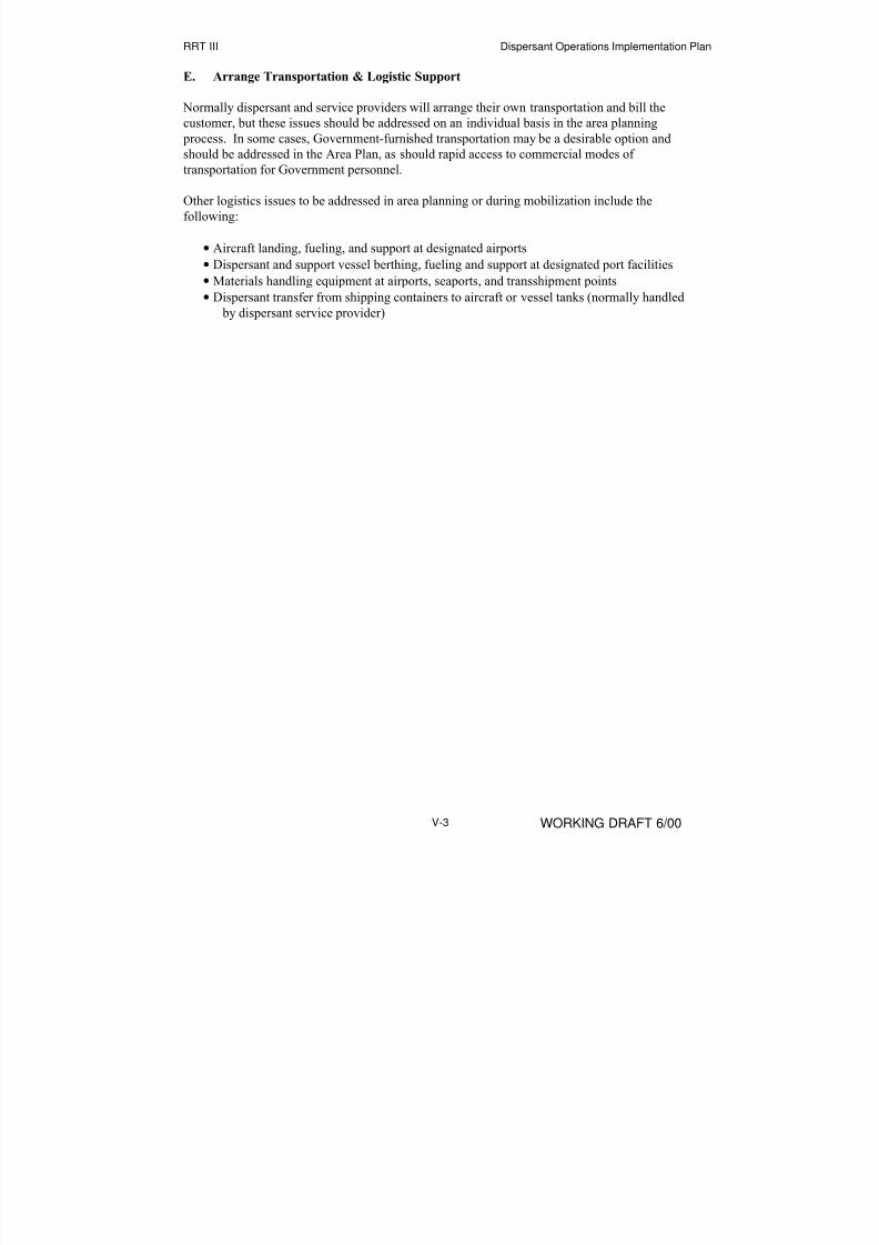
8/3/2019 Guia de selección de tecnologias aplicadas a derrames Vol II
http://slidepdf.com/reader/full/guia-de-seleccion-de-tecnologias-aplicadas-a-derrames-vol-ii 52/298
RRT III Dispersant Operations Implementation Plan
WORKING DRAFT 6/00V-3
E. Arrange Transportation & Logistic Support
Normally dispersant and service providers will arrange their own transportation and bill the
customer, but these issues should be addressed on an individual basis in the area planning
process. In some cases, Government-furnished transportation may be a desirable option and
should be addressed in the Area Plan, as should rapid access to commercial modes of
transportation for Government personnel.
Other logistics issues to be addressed in area planning or during mobilization include the
following:
• Aircraft landing, fueling, and support at designated airports
• Dispersant and support vessel berthing, fueling and support at designated port facilities
• Materials handling equipment at airports, seaports, and transshipment points
• Dispersant transfer from shipping containers to aircraft or vessel tanks (normally handled
by dispersant service provider)

8/3/2019 Guia de selección de tecnologias aplicadas a derrames Vol II
http://slidepdf.com/reader/full/guia-de-seleccion-de-tecnologias-aplicadas-a-derrames-vol-ii 53/298
RRT III Dispersant Operations Implementation Plan
WORKING DRAFT 6/00V-4
This Page Intentionally Left Blank

8/3/2019 Guia de selección de tecnologias aplicadas a derrames Vol II
http://slidepdf.com/reader/full/guia-de-seleccion-de-tecnologias-aplicadas-a-derrames-vol-ii 54/298
RRT III Dispersant Operations Implementation Plan
WORKING DRAFT 6/00VI-1
VI. IMPLEMENT DISPERSANT OPERATIONS PLAN
Table VI - 1 – Implement Dispersant Operations Plan -
Checklist and Roadmap
√ Required Action Initial Responsibility DOIPPage #
Implement Plan in Emergency Phase
Dispersant Operations
Group Supervisor (DOGS)
(Name / Watch, Quarter & Station Bill Assignment)
VI -1
(ACP Page #)
Integrate Dispersant Operations Plan into
IAP
DOGS / PLANNING
SECTION CHIEF
(Name / Watch, Quarter & Station Bill Assignment)
VI -2
(ACP Page #)
VI. Implement Dispersant Operations Plan - Table of Contents
Page
A. Implement Incident-specific Dispersant Plans in the
Emergency Phase.............................................................................................. VI-1
B. Integrate Dispersant Plans into the Incident Action Plan................................. VI-2
A. Implement Incident-specific Dispersant Operations Plan in the Emergency Phase:
Dispersant operations will be conducted under the direction of the Dispersant Operations Group
Supervisor (DOGS) within the incident command structure prescribed by the FOSC/Unified
Command, and in accordance with the Dispersant Operations Plan developed for the incident.
As previously discussed, a good portion of the mobilization and perhaps the early phases of the
dispersant application may be conducted in the emergency phase of the operation, prior to the
development and approval of the initial Incident Action Plan. It is critical especially in the
emergency phase that dispersant operations be carefully controlled and coordinated with other
phases of the overall response operation, particularly if mechanical containment and recovery,
and/or in-situ burning operations will be ongoing in adjacent areas. In addition, dispersant
application whether by aircraft or vessel must be properly coordinated with spotter aircraft as
well as with dispersant monitoring and dispersant observation efforts, in accordance with the
Area Contingency Plan. And of course the Area Plan dispersant guidance must be in compliance
with the requirements of the Region III Regional Contingency Plan. The required Region III
approval process, including pre-approvals, and the Region III monitoring protocols are worthy of
particular attention.
The technical or operational details of aerial or surface vessel dispersant application are beyond
the scope of this DOIP. Training and experience of the DOGS and other members of the

8/3/2019 Guia de selección de tecnologias aplicadas a derrames Vol II
http://slidepdf.com/reader/full/guia-de-seleccion-de-tecnologias-aplicadas-a-derrames-vol-ii 55/298
RRT III Dispersant Operations Implementation Plan
WORKING DRAFT 6/00VI-2
Dispersant Operations Group should make them knowledgeable of such details, but they will
likely remain the responsibility of the dispersant application service providers.
The Region IV “Incident Command Functional Checklists for Dispersant Use” (attachment IV-
8), introduced in section IV of this DOIP describe recommended roles, responsibilities and tools
for Dispersant Operations group personnel. Dispersant application service provider personnel
will fill some of these positions.
B. Integrate Dispersant Plans into the Incident Action Plan
The incident specific dispersant operations plan may be developed and implementation initiated
prior to development of the initial incident action plan. Nevertheless, the flow of information
between the Dispersant Operations Group, the Operations Section Chief, and the rest of the
response organization must be initiated at the earliest stages of the response and maintained in
accordance with FOSC/Area Contingency Plan direction. Proper integration of dispersant
operations into the overall response in the emergency phase, through a disciplined system for
information flow, will simplify dispersant operations integration into the incident action plan.

8/3/2019 Guia de selección de tecnologias aplicadas a derrames Vol II
http://slidepdf.com/reader/full/guia-de-seleccion-de-tecnologias-aplicadas-a-derrames-vol-ii 56/298
RRT III Dispersant Operations Implementation Plan
WORKING DRAFT 6/00VII-1
VII. COORDINATE DISPERSANT MONITORING PROTOCOL
Table VII - 1 – Dispersant Monitoring - Checklist and ROADMAP
√ Required Action 3) Initial ResponsibilityDOIP
Page #
Mobilize Monitoring Team
Dispersant Operations
Group Supervisor (DOGS)
(Name / Watch, Quarter & Station Bill Assignment)
VII -1
(ACP Page #)
Provide Monitoring Support Platform(s)
DOGS / LOGISTICS
(Name / Watch, Quarter & Station Bill Assignment)
VII -1
(ACP Page #)
Conduct Monitoring in Coordination with
Dispersant Application
DOGS / Monitoring Unit
Leader
(Name / Watch, Quarter & Station Bill Assignment)
VII -2
(ACP Page #)
VII. Dispersant Monitoring - Table of Contents
Page
A. Mobilize Monitoring Team ....................................................................................... VII-1
B. Provide Monitoring Support Platform(s) .................................................................. VII-1
C. Conduct Monitoring in Coordination with Dispersant Application.......................... VII-2
Table VII-1 Dispersant Monitoring Checklist and Roadmap ........................................ VII-1
Attachments:
Dispersant Effectiveness Monitoring Aerial Checklist.................................... Attach. VII-A
Dispersant Effectiveness Monitoring Waterborne Checklist ........................... Attach. VII-B
A. Mobilize Monitoring Team
The FOSC’s designated Monitoring Team should be notified of the spill by the FOSC’s duty
section, as addressed in section I of this DOIP, and should be mobilized by the DOGS when
dispersant application resources are mobilized. The Coast Guard Strike Teams are being trainedand equipped to conduct dispersant monitoring.
B. Provide Monitoring Support Platform(s)
The emergency phase of a spill response operation is not a good time to determine monitoring
support vessel requirements and to locate suitable vessels. The Area Committee should
coordinate with the designated Monitoring Team(s) during the Area planning process to
determine monitoring vessel requirements. Local/area/regional vessels determined suitable for

8/3/2019 Guia de selección de tecnologias aplicadas a derrames Vol II
http://slidepdf.com/reader/full/guia-de-seleccion-de-tecnologias-aplicadas-a-derrames-vol-ii 57/298
RRT III Dispersant Operations Implementation Plan
WORKING DRAFT 6/00VII-2
monitoring team support should be so listed in the Area Contingency Plan, and arrangements
(contracts, interagency agreements, etc.) should be established to ensure ready vessel availability.
Unless other arrangements are in place, when the Monitoring Team is mobilized, the
FOSC/Unified Command’s Logistics Section should arrange adequate monitoring vessel support.
C. Conduct Monitoring in Coordination with Dispersant Application
The Monitoring Team’s activities will be conducted in accordance with regional Contingency
Plan guidance. The Area Contingency Plan should address the organization of the Dispersant
Operations Group in the Incident Command System (ICS) structure. The Region IV approach,
placing the Monitoring Team under the control of the Dispersant Operations Group Supervisor,
as indicated in attachment IV-G, and discussed in DOIP section IV is recommended.
Region IV’s “Dispersant Effectiveness Monitoring Aerial Checklist” and their “Dispersant
Effectiveness Monitoring Waterborne Checklist” (attachments VII-1 and VII-2 are provided for
reference).

8/3/2019 Guia de selección de tecnologias aplicadas a derrames Vol II
http://slidepdf.com/reader/full/guia-de-seleccion-de-tecnologias-aplicadas-a-derrames-vol-ii 58/298
RRT III Dispersant Operations Implementation Plan
WORKING DRAFT 6/00VIII-1
VIII. COORDINATE DISPERSANT OBSERVER PROGRAM
Table VIII - 1 – Dispersant Observer Program - Checklist and Roadmap
√ Required Action Initial ResponsibilityDOIP
Page #
Determine Observer Program
Requirements
Dispersant Observation Team
Leader
(Name / Watch, Quarter & Station Bill Assignment)
VIII -1
(ACP Page #)
Determine Support Requirements
Dispersant Observation Team
Leader
(Name / Watch, Quarter & Station Bill Assignment)
VIII-2
(ACP Page #)
Ensure Observer Safety
Dispersant Observation Team
Leader
(Name / Watch, Quarter & Station Bill Assignment)
VIII -2
(ACP Page #)
Ensure Adequate Communications
Dispersant Observation Team
Leader
(Name / Watch, Quarter & Station Bill Assignment)
VIII -2
(ACP Page #)
Coordinate Observer Program within
Dispersant Operations Group
Dispersant Observation Team
Leader
(Name / Watch, Quarter & Station Bill Assignment)
VIII -2
(ACP Page #)
VIII. Coordinate Dispersant Observer Program - Table of Contents
Page
A. Introduction ...................................................................................................... VIII-1
B. Determine Observer Program Requirements ................................................... VIII-2
C. Determine Support Requirements .................................................................... VIII-2
D. Ensure Observer Safety.................................................................................... VIII-2
E. Ensure Adequate Communications .................................................................. VIII-2
F. Coordinate Observer Program within Dispersant Operations Group............... VIII-2
Table VIII-1 Dispersant Observer Program Checklist and Roadmap VIII-1
A. Introduction
State and Federal Resource Trustees and other Stakeholders may wish to assign representatives
to observe the effectiveness of dispersant operations, independent of the assigned Monitoring
Team. Observer status should be authorized by the Unified Command, and their participation
controlled by the Dispersant Operations Group Supervisor, within the ICS. Observers have no
operational authority or responsibility by virtue of the observer designation.

8/3/2019 Guia de selección de tecnologias aplicadas a derrames Vol II
http://slidepdf.com/reader/full/guia-de-seleccion-de-tecnologias-aplicadas-a-derrames-vol-ii 59/298
RRT III Dispersant Operations Implementation Plan
WORKING DRAFT 6/00VIII-2
B. Determine Observer Program Requirements
The Dispersant Observation Team Leader coordinates with State and Federal Trustees and
determines the scope of the required Observer Program. Key trustees may have already been
notified of the operation by the FOSC’s duty section as indicated in section I of this DOIP.
C. Determine Support Requirements
When the scope of the Observation Program has been estimated, the Dispersant Observation
Team Leader coordinates with the Dispersant Operations Group Supervisor and relays
observation aircraft and/or vessel requirements via the chain of command to the Logistics
section.
D. Ensure Observer Safety
The Dispersant Observation Team Leader will coordinate with the Safety Officer and the
observation aircraft and/or vessel operators as required to ensure that all observers receive
appropriate safety briefings and that they are equipped with required personal protective
equipment (PPE) per the Site Safety Plan and best commercial practice.
E. Ensure Adequate Communications
The Dispersant Observation Team Leader will coordinate with the DOGS and with the Logistics
Section’s Communications Unit to ensure that the observation vessels and/or aircraft can
communicate with other vessels, aircraft, or ground stations as required. Appropriate call signs
and assigned frequencies should be in accordance with the incident Communication Plan.
Communication between the observer aircraft and/or vessel with the Forward Air Controller
(normally in the Spotter Aircraft per the Region IV recommended organization) is a critical
safety consideration.
F. Coordinate Observer Program within Dispersant Operations Group
The Dispersant Observation Team Leader is responsible for ensuring that observer activities are
conducted in accordance with the incident-specific Dispersant Operations Plan and the direction
of the Dispersant Operations Group Supervisor.

8/3/2019 Guia de selección de tecnologias aplicadas a derrames Vol II
http://slidepdf.com/reader/full/guia-de-seleccion-de-tecnologias-aplicadas-a-derrames-vol-ii 60/298
RRT III Dispersant Operations Implementation Plan
WORKING DRAFT 6/00IX-1
IX. DEMOBILIZE DISPERSANT RESOURCES
Table IX - 1 – Demobilization - Checklist and Roadmap
√ Required Action Initial ResponsibilityDOIP
Page #
Personnel Demobilization
Dispersant Operations Group
Supervisor
(Name / Watch, Quarter & Station Bill Assignment)
IX -1
(ACP Page #)
Equipment Demobilization
Dispersant Operations Group
Supervisor
(Name / Watch, Quarter & Station Bill Assignment)
IX-2
(ACP Page #)
VIII. Dispersant Operations Demobilization - Table of Contents
Page
A. Introduction ...................................................................................................... IX-1
B. Personnel Demobilization ................................................................................ IX-1
C. Equipment Demobilization ............................................................................. IX-2
Table IX-1 Demobilization Checklist and Roadmap.......................................... IX-1
A. Introduction:
The Dispersant Operations Group Supervisor (DOGS) coordinates with the Planning Section
Demobilization Unit in developing a dispersant resources demobilization plan to ensure
unneeded resources are released as soon as possible. Most resources will be demobilized upon
termination of dispersant operations, but the DOGS must be prepared to demobilize individual
resources whenever it is determined they are no longer needed. The Logistics Section should
approve the release of resources to ensure that those resources, such as support vessels or aircraft,
are not needed to support other phases of the response. The FOSC/Unified Command must
approve demobilization of resources prior to release.
B. Personnel Demobilization
The Demobilization Unit of the Planning Section will develop a demobilization plan with input
from the Dispersant Operations Group Supervisor and others. Prior to personnel release, the
DOGS must debrief key personnel for lessons learned and require them to “sign out” with
designated officials to ensure required reports, cost documentation, issued equipment (e.g. radios
and personal protective equipment), and related items are collected / accounted for in a timely
manner.

8/3/2019 Guia de selección de tecnologias aplicadas a derrames Vol II
http://slidepdf.com/reader/full/guia-de-seleccion-de-tecnologias-aplicadas-a-derrames-vol-ii 61/298
RRT III Dispersant Operations Implementation Plan
WORKING DRAFT 6/00IX-2
C. Equipment Demobilization
Demobilization of dispersant materials and equipment will be in accordance with the
demobilization plan. Normally the DOGS will provide notification through the chain of
command to Logistics and Finance Sections when material and equipment is no longer neededand the DOGS recommends release. Equipment will normally be cleaned, refurbished and
inspected prior to release. Return shipment to point of origin may be by a more economical
transportation mode than mobilization, but “portal to portal” daily equipment rental rates should
be considered (i.e. daily rental generally applies during return shipment). All unused dispersant
should be reclaimed from application equipment. The cost of return shipment of unused
dispersant should be balanced against replacement cost and stockpiling within the Area or
Region.

8/3/2019 Guia de selección de tecnologias aplicadas a derrames Vol II
http://slidepdf.com/reader/full/guia-de-seleccion-de-tecnologias-aplicadas-a-derrames-vol-ii 62/298
RRT III Dispersant Operations Implementation Plan
Attachments
ATTACHMENTS

8/3/2019 Guia de selección de tecnologias aplicadas a derrames Vol II
http://slidepdf.com/reader/full/guia-de-seleccion-de-tecnologias-aplicadas-a-derrames-vol-ii 63/298
RRT III Dispersant Operations Implementation Plan
Attachments
This Page Intentionally Left Blank

8/3/2019 Guia de selección de tecnologias aplicadas a derrames Vol II
http://slidepdf.com/reader/full/guia-de-seleccion-de-tecnologias-aplicadas-a-derrames-vol-ii 64/298
RRT III Dispersant Operations Implementation Plan
Attachment II-A-1 WORKING DRAFT 6/00
ATTACHMENT II-A
SITUATION AND DISPERSANT APPLICABILITY SUMMARY
SITUATION
A. Release Source:
* Vessel Name:
* Facility Name:
* Pipeline:
* Other:
B. Date/Time of Release: /
C. Oil Description: (See Attachment A – List of Oil Products that enter each
COTP Zone)
* Oil Type:
+ Refined:
+ Crude:
Oil Name:
* Specific/API Gravity:
* Viscosity: @ temperature F
* Pour Point:
* Sulfur Content:
D. Dispersibility of Released Oil
* Specific Fresh Oil Dispersibility (See Reference D)General Dispersibility Relative to API Gravity (See
Reference E)
* Emulsification (See Reference F)
Caution: The ability of the ADIOS model
to predict viscosity is very
unreliable for the great majority
of oils in the ADIOS database
because of the lack of data on
emulsification
E. Type of Release:
* Instantaneous:
* Continuous:
• Intermittent:
• Other:

8/3/2019 Guia de selección de tecnologias aplicadas a derrames Vol II
http://slidepdf.com/reader/full/guia-de-seleccion-de-tecnologias-aplicadas-a-derrames-vol-ii 65/298
RRT III Dispersant Operations Implementation Plan
Attachment II-A-2 WORKING DRAFT 6/00
ATTACHMENT II-A, CONT.
F. Release Location:
* Latitude:
Longitude:
G. Amount released:
* Gal.
* Bbls.
H. Is there a pre-approval plan:
* Yes (See Reference A for applicable plan)
* No
I. On-Scene Weather:* Winds: (From) @ (mph)
* Visibility: (statute miles)
* Ceiling: (feet)
* Precip: (fog, rain, etc.)
J. Water depth @ release location:
* Depth: (meters)
K. CAN DISPERSANTS BE USED?:
YES (pre-approval situation)
NO (not appropriate/feasible)
MAYBE (case by case approval required)
SHOULD WE USE DISPERSANTS?)

8/3/2019 Guia de selección de tecnologias aplicadas a derrames Vol II
http://slidepdf.com/reader/full/guia-de-seleccion-de-tecnologias-aplicadas-a-derrames-vol-ii 66/298
RRT III Dispersant Operations Implementation Plan
Attachment II-B-1 WORKING DRAFT 6/00
ATTACHMENT II-B
DISPERSANT USE DECISION / IMPLEMENTATION ELEMENT CHECKLIST Completed by ……..
Note: Need all"YES" answers before dispersant use is acceptable.
DECISION ELEMENT1. Is the spill/oil dispersible?
Oil is generally dispersible if: API Gravity is more than 17
YES NO Pour Point is less than 10 F (5.5 C) below
ambient temperature
Viscosity is less than 10,000 centistokes
Note: Some modern dispersants may be formulated to be effective on a wider range of
oil properties. The choices of dispersants listed on the NCP’s National Product
Schedule are limited. To answer this question you should look at whichdispersant would the most effective given the type of oil.
2. Have environmental tradeoffs of dispersant use
indicated that use should be considered ?
YES NO Note: This is one of the more difficult questions. Dispersant toxicity
assessment information found in Appendix V of the RRT pre-approval
agreements may assist in this decision.
3. Is the chosen dispersant likely to be effective?
Consider:
YES NO* effectiveness of dispersant application to the oil;
* dispersant-to-oil application ratio;
* oil slick thickness;
* distribution of oil slick on the water;
* droplet size distribution in aerial spray;
* oil viscosity;
* energy input;
* suspended particles in water (sedimentation);
* weathering of oil;
* emulsification of oil;
* oil composition;* dispersant composition;
* water salinity; and
* temperature.
* dispersant type compatible with application means
Note: A preliminary effectiveness test such as the standard flask swirling
method is highly recommended.

8/3/2019 Guia de selección de tecnologias aplicadas a derrames Vol II
http://slidepdf.com/reader/full/guia-de-seleccion-de-tecnologias-aplicadas-a-derrames-vol-ii 67/298
RRT III Dispersant Operations Implementation Plan
Attachment II-B-2 WORKING DRAFT 6/00
ATTACHMENT II-B, CONT.
Note: Need all"YES" answers before dispersant use is acceptable.
DECISION ELEMENT
4. Can dispersant application be conducted safely and
effectively given the physical
environment?
YES NO
Environmental parameters:
* winds less than or equal to 25 knots
* visibility greater than or equal to 3 miles
* ceiling greater than or equal to 1000 feet
* operations during daylight hours only
5. Are sufficient equipment and personnel available to
conduct aerial dispersant application operations within the
window of opportunity?
YES NO Note: Refer to elements and position descriptions under the
Dispersant Operations Group Supervisor in the Operations
Section…Other tools are available to assess this such as the
NOAA Dispersant Mission Planner.
6. Has a Site Safety Plan for dispersant operations been
completed?
YES NO
7. Is the spill/oil to be dispersed within a Pre-Approved Zone?
Refer to Section II within the applicable RRT Dispersant Pre-
Approval Agreement
YES NO If the spill/oil is NOT in a Pre-Approved Zone, has
approval been granted?
Submit "RRT Documentation/Application Form for
Dispersant Use" to the Incident
Specific RRT members with request for approval.Dispersant use in non-approved areas must be requested by
the OSC and approved by EPA and the affected state(s)
after consultation with
DOC and DOI

8/3/2019 Guia de selección de tecnologias aplicadas a derrames Vol II
http://slidepdf.com/reader/full/guia-de-seleccion-de-tecnologias-aplicadas-a-derrames-vol-ii 68/298
RRT III Dispersant Operations Implementation Plan
Attachment II-B-3 WORKING DRAFT 6/00
ATTACHMENT II-B, CONT.
Note: Need all"YES" answers before dispersant use is acceptable.
DECISION ELEMENT8. Are the necessary equipment and trained personnel
available to conduct the recommended monitoring
operations?
YES NO The recommended monitoring protocol in each RRT region
is the Special Monitoring for Advanced Response
Technologies or SMART. The Gulf Strike Team or
Atlantic Strike Team is available to support and provide
monitoring assistance.
It may not be appropriate to base Go/No Go or
continue/discontinue decisions solely on results from theSMART monitoring team since dispersant effectiveness is
often delayed or not totally and easily conclusive.
Monitoring is recommended but not strictly
required…should not be a showstopper for operation.
9. Has the overflight to assure that endangered species are
not in the application area been conducted?
YES NO The provisions of the Section 7 consultation in regard to
each RRT Pre-Approval Agreement requires an overflightof the application area to ensure endangered species are not
threatened or endangered by the operation.
10. Has a Dispersant Operations Plan been completed?
Attached within this plan is a Dispersant Operations Plan
YES NO template. The completion of this template should provide
the OSC and Unified Command with a suitable and
complete plan to support and implement the dispersant
effort.

8/3/2019 Guia de selección de tecnologias aplicadas a derrames Vol II
http://slidepdf.com/reader/full/guia-de-seleccion-de-tecnologias-aplicadas-a-derrames-vol-ii 69/298
RRT III Dispersant Operations Implementation Plan
Attachment II-B-4 WORKING DRAFT 6/00
This Page Intentionally Left Blank

8/3/2019 Guia de selección de tecnologias aplicadas a derrames Vol II
http://slidepdf.com/reader/full/guia-de-seleccion-de-tecnologias-aplicadas-a-derrames-vol-ii 70/298
RRT III Dispersant Operations Implementation Plan
Attachment IV-A-1 WORKING DRAFT 6/00

8/3/2019 Guia de selección de tecnologias aplicadas a derrames Vol II
http://slidepdf.com/reader/full/guia-de-seleccion-de-tecnologias-aplicadas-a-derrames-vol-ii 71/298
RRT III Dispersant Operations Implementation Plan
Attachment IV-A-2 WORKING DRAFT 6/00
This Page Intentionally Left Blank

8/3/2019 Guia de selección de tecnologias aplicadas a derrames Vol II
http://slidepdf.com/reader/full/guia-de-seleccion-de-tecnologias-aplicadas-a-derrames-vol-ii 72/298
RRT III Dispersant Oper
Attachment IV-B-1
1. Key Operational Factors
a. Weather
Wind OK Not OK
Visibility OK Not OK
Clearance OK Not OK
b. Window of Opportunity 24 hrs
c. Daylight Hours Remaining 12 hrs
d. Enter Smallest Window 12 hrs
e. Platform Data
Type:
Transit Speed 150 Knots
Application Speed 120 Knots
Swath 150 Feet
Coverage Rate 0.697412462 Acres/s
Coverage Rate 30380.4 SqFt/s
System Pump Rate 100 gpm
Dispersant Payload 5000 gals
Dispersant Actual Load 3000 gals
Ideal Oil/Dispersant Ratio 20
Oil Treatable/Ideal Ratio 1428.571429 bbls
% Oil treatable w/ideal ratio 89.28571429 %
#Dispersant Loads/Oil Volume 1.12
Max Acres/Disp Load 1255.342432 Acres
Bbls Treated based on Speed 3195.553248 bbls
Actual Oil/Dispersant Ratio 44.73774547
Dispersant Gals/Acre 2.389786183
Time to Deplete Stockpile 0.5 hrs
f. Spotter Data
Type: DC-4
Transit Speed 100 Knots

8/3/2019 Guia de selección de tecnologias aplicadas a derrames Vol II
http://slidepdf.com/reader/full/guia-de-seleccion-de-tecnologias-aplicadas-a-derrames-vol-ii 73/298
RRT III Dispersant Oper
Attachment IV-B-2
2. Spill Stats
Spilled Oil 2000 bbls
%Spilled Oil Evaporated/Dispersed 80 %
Total Treatable Oil 1600 bbls
Slick Area 632.56576 Acres
Average Slick Thickness 0.1 mmDistance: Staging to Treatment Area 50 NM
3. Resource Locations and Distances Location Distance to Staging Area Transportation Unit
Staging Area
Dispersant:
In Product Schedule? Yes No
Amount: Gals
Platform Location
Dispersant Location
Application System Location
Spotter Location
4. Time to Get Systems Ready (hrs) Stockpile Platform Application Spotter
Personnel Recall 2 1 1 1
Loading/Transport to Staging Area 0 0 0 0
Totals 2 1 1 1
Loading of Stockpile 3
Loading of Application System 0
Enter Total Time for Ready System 5
Enter Slowest Transport Speed (kn) 100
Time to Arrive at Treatment Area 0.5
Time for Positioning 0.5Total Time to Application 6
Amount of Window Time Left 6
Time remaining after stockpile use 5.5
Return, Reload, Back O/S Time 4.5
Amount of Window Time Left 1
Dispersant Platforms Spotter Aircraft Dispersant Stock

8/3/2019 Guia de selección de tecnologias aplicadas a derrames Vol II
http://slidepdf.com/reader/full/guia-de-seleccion-de-tecnologias-aplicadas-a-derrames-vol-ii 74/298
RRT III Dispersant Oper
Attachment IV-B-3
Platform Type: Platform Type: Type
Transit Speed 150 Knots Transit Speed 150 Knots Amount
Application Speed 120 Knots Aircraft Call Sign Location
Swath 150 Feet Location POC
Coverage Rate 0.69741
2
Acres/s POC Phone Number
System Pump Rate 210 gpm Phone Number: Fax Number:
Dispersant Payload 5000 gals Fax Number: Other
Oil Treatable (DOR 1/20) 100000 gals
Call Sign Spotter Aircraft Dispersant Stock
Location Platform Type: Type
POC Transit Speed 150 Knots Amount
Phone Number: Aircraft Call Sign Location
Fax Number: Location POC
Platform Type: POC Phone Number
Transit Speed 150 Knots Phone Number: Fax Number:
Application Speed 120 Knots Fax Number: Other
Swath 150 FeetCoverage Rate 0.69741
2
Acres/s Spotter Aircraft Dispersant Stock
System Pump Rate 210 gpm Platform Type: Type
Dispersant Payload 5000 gals Transit Speed 150 Knots Amount
Oil Treatable (DOR 1/20) 100000 gals Aircraft Call Sign Location
Call Sign Location POC
Location POC Phone Number
POC Phone Number: Fax Number:
Phone Number: Fax Number: Other
Fax Number:
Platform Type: Monitor Platform Staging Area
Transit Speed 150 Knots Platform Type: Name
Application Speed 120 Knots Transit Speed 150 Knots Location
Swath 150 Feet Call Sign Loading Ability
Coverage Rate 0.69741
2
Acres/s Location Airstrip/Pier Spac
System Pump Rate 210 gpm POC POC
Dispersant Payload 5000 gals Phone Number: Phone Number
Oil Treatable (DOR 1/20) 100000 gals Fax Number: Fax Number:

8/3/2019 Guia de selección de tecnologias aplicadas a derrames Vol II
http://slidepdf.com/reader/full/guia-de-seleccion-de-tecnologias-aplicadas-a-derrames-vol-ii 75/298
RRT III Dispersant Oper
Attachment IV-B-4
Call Sign
Location Monitor Platform Staging Area
POC Platform Type: Name
Phone Number: Transit Speed 150 Knots Location
Fax Number: Call Sign Loading Ability
Platform Type: Location Airstrip/Pier SpacTransit Speed 150 Knots POC POC
Application Speed 120 Knots Phone Number: Phone Number
Swath 150 Feet Fax Number: Fax Number:
Coverage Rate 0.69741
2
Acres/s
System Pump Rate 210 gpm Monitor Platform Staging Area
Dispersant Payload 5000 gals Platform Type: Name
Oil Treatable (DOR 1/20) 100000 gals Transit Speed 150 Knots Location
Call Sign Call Sign Loading Ability
Location Location Airstrip/Pier Spac
POC POC POC
Phone Number: Phone Number: Phone NumberFax Number: Fax Number: Fax Number:
8/3/2019 Guia de selección de tecnologias aplicadas a derrames Vol II
http://slidepdf.com/reader/full/guia-de-seleccion-de-tecnologias-aplicadas-a-derrames-vol-ii 76/298
RRT III Dispersa
Attachment IV-C-1
DISPERSANT APPLICATION PLATFORM CAPABILITY DECISIO
Platform
Payload
(Gallons)
Approximate
Min/Max
Dosage
(Gallons per
Acre)
Coverage/Sortie
5 gal/acre
Dosage(Acres)
Coverage/ Sortie *
10 gal/acre
Dosage(Acres)
Coverage/ Sortie *
Max gal/acre
Dosage(Acres)
Maximum
Operational
Time
(Hours)
Bell 212 with Bucket 300 0.8/21.5 60 30 14 1.7
C130 with ADDS 5000 1.4/16.4 1000 500 305 12
C130 with MASS 2000 2.6/19.4 400 200 103 12
DC-4 2170 0.8/10.3 434 217 211 4.5
DC-6B 3000 4.3/19.8 600 300 152 5.5
Thrush 510 -/- 102 51 - 4.5
Air Tractor 801 800 -/- 160 80 - 2.5
Large Vessel (>100ft) 3000 2.2/35.8 600 300 84 100
Small Vessel
(20-40 feet)
600 1.1/71.7 120 60 8 20
Fire Monitor Vessel
Dependent
5/20 Vessel
Dependent
Vessel
Dependent
Vessel
Dependent
Vessel
Dependent
Notes: * Assumes Full Payload** Small platforms may be the best choice for larger spills to treat the leading edge and thicker portions
effective platform can arrive on scene.
*** For notes (1) through (10) see next page.
8/3/2019 Guia de selección de tecnologias aplicadas a derrames Vol II
http://slidepdf.com/reader/full/guia-de-seleccion-de-tecnologias-aplicadas-a-derrames-vol-ii 77/298
RRT III Dispersant Operations Implementation Plan
Attachment IV-C-2 WORKING DRAFT 6/00
DISPERSANT APPLICATION PLATFORM CAPABILITY
DECISION
MATRIX NOTES
NOTES:
(1) For relatively small spills and where transit distance is short. Platform has
relatively short operational duration and spray capacity.
(2) Most capable platform for large spills. Has high endurance and spray capacity. If a
Coast Guard C-130 Hercules is used to support ADDS-Pack deployment, in
accordance with existing MOAs, a modification (removal of rails in cargo bay) to
the aircraft setup will be necessary which would take 6 to 8 hours to complete. This
delay should be accounted for when considering aircraft availability.
(3) Good platform for endurance. Spray capacity is less than half of Adds-Pack. For
medium to large spills.
(4) Use for medium to large spills. Moderate endurance. Spray capacity is similar.
(5) Use for medium to large spills. Moderate endurance. Spray capacity is similar.
(6) Crop-duster type aircraft good for small to medium spills. Can be turned around
quickly for repeated treatments of larger slicks. Spray nozzles should be calibrated
specifically for dispersant operations to obtain correct droplet size and spray pattern.
(7) Crop-duster type aircraft good for small to medium spills. Can be turned around
quickly for repeated treatments of larger slicks. Spray nozzles should be calibrated
specifically for dispersant operations to obtain correct droplet size and spray pattern.
(8) High endurance and spray capacity, but has slow operational speed.
(9) Small to medium slicks or surgical treatment of the slick’s leading edge. Slow
speed and low spray capacity.
(10) May be good for surgical treatment of the slick’s leading edge and thickest portions
of the slick. Calibration and delivery rate may be difficult to control.

8/3/2019 Guia de selección de tecnologias aplicadas a derrames Vol II
http://slidepdf.com/reader/full/guia-de-seleccion-de-tecnologias-aplicadas-a-derrames-vol-ii 78/298
RRT III Dispersant Operations Implementation Plan
Attachment IV-D-1 WORKING DRAFT 6/00

8/3/2019 Guia de selección de tecnologias aplicadas a derrames Vol II
http://slidepdf.com/reader/full/guia-de-seleccion-de-tecnologias-aplicadas-a-derrames-vol-ii 79/298
RRT III Dispersant Operations Implementation Plan
Attachment IV-D-2 WORKING DRAFT 6/00

8/3/2019 Guia de selección de tecnologias aplicadas a derrames Vol II
http://slidepdf.com/reader/full/guia-de-seleccion-de-tecnologias-aplicadas-a-derrames-vol-ii 80/298
RRT III Dispersant Operations Implementation Plan
Attachment IV-D-3 WORKING DRAFT 6/00

8/3/2019 Guia de selección de tecnologias aplicadas a derrames Vol II
http://slidepdf.com/reader/full/guia-de-seleccion-de-tecnologias-aplicadas-a-derrames-vol-ii 81/298
RRT III Dispersant Operations Implementation Plan
Attachment IV-D-4 WORKING DRAFT 6/00
This Page Intentionally Left Blank

8/3/2019 Guia de selección de tecnologias aplicadas a derrames Vol II
http://slidepdf.com/reader/full/guia-de-seleccion-de-tecnologias-aplicadas-a-derrames-vol-ii 82/298
RRT III Dispersant Operations Implementation Plan
Attachment IV-E-1 WORKING DRAFT 6/00

8/3/2019 Guia de selección de tecnologias aplicadas a derrames Vol II
http://slidepdf.com/reader/full/guia-de-seleccion-de-tecnologias-aplicadas-a-derrames-vol-ii 83/298
RRT III Dispersant Operations Implementation Plan
Attachment IV-E-2 WORKING DRAFT 6/00
This Page Intentionally Left Blank

8/3/2019 Guia de selección de tecnologias aplicadas a derrames Vol II
http://slidepdf.com/reader/full/guia-de-seleccion-de-tecnologias-aplicadas-a-derrames-vol-ii 84/298
RRT III Dispersant Operations Implementation Plan
Attachment IV-F-1 WORKING DRAFT 6/00

8/3/2019 Guia de selección de tecnologias aplicadas a derrames Vol II
http://slidepdf.com/reader/full/guia-de-seleccion-de-tecnologias-aplicadas-a-derrames-vol-ii 85/298
RRT III Dispersant Operations Implementation Plan
Attachment IV-F-2 WORKING DRAFT 6/00
This Page Intentionally Left Blank

8/3/2019 Guia de selección de tecnologias aplicadas a derrames Vol II
http://slidepdf.com/reader/full/guia-de-seleccion-de-tecnologias-aplicadas-a-derrames-vol-ii 86/298
RRT III Dispersant Operations Implementation Plan
Attachment IV-G-1 WORKING DRAFT 6/00
ICS ORGANIZATION CHART FOR DISPERSANT USE
FOSC or IncidentCommanders
(Unified Command)
Operations
DispersantOperationGroupSupervisor
Spotter Aircraft
MonitoringAircraft/Vessel
SprayAircraft/Vessel
ObservationAircraft/Vessel
Planning
SSC/Technical
Specialists

8/3/2019 Guia de selección de tecnologias aplicadas a derrames Vol II
http://slidepdf.com/reader/full/guia-de-seleccion-de-tecnologias-aplicadas-a-derrames-vol-ii 87/298
RRT III Dispersant Operations Implementation Plan
Attachment IV-G-2 WORKING DRAFT 6/00
This Page Intentionally Left Blank

8/3/2019 Guia de selección de tecnologias aplicadas a derrames Vol II
http://slidepdf.com/reader/full/guia-de-seleccion-de-tecnologias-aplicadas-a-derrames-vol-ii 88/298
RRT III Dispersant Operations Implementation Plan
Attachment IV-H-1 WORKING DRAFT 6/00
ICS DISPERSANT USE ORGANIZATIONAL RELATIONSHIPS
NOTES:
1. The dotted lines above depict the cross-functional relationships between Operations,
Planning, and Logistics to successfully implement dispersant activities.
2. Flexibility is paramount during dispersant operations. The IC/UC may choose to place the Monitoring and
Observation Aircraft/Vessel(s) under the guide of the Planning Section. Normally monitors and observers
pass their information directly to the Technical Specialists located under Planning (e.g. similar to SCAT
Teams, field observers, etc.). Either scheme will work as long as there exists a strong working/reporting
relationship between Operations and Planning. Their placement within functional schematic diagram is
totally at the IC/UC discretion.
FOSC or Incident Commanders
(Unified Command)
Operations Planning Logistics Finance
Dispersant
Operation Group
Supervisor
Technical
Specialists
Support
Branch
Procurement
Unit
Supply Unit
Ground
Support Unit
Spotter Aircraft
Monitoring
Aircraft/Vessel
Spray
Aircraft/Vessel
Observation
Aircraft/Vessel
Cost/Time Unit
VesselSupport Unit

8/3/2019 Guia de selección de tecnologias aplicadas a derrames Vol II
http://slidepdf.com/reader/full/guia-de-seleccion-de-tecnologias-aplicadas-a-derrames-vol-ii 89/298
RRT III Dispersant Operations Implementation Plan
Attachment IV-H-2 WORKING DRAFT 6/00
This Page Intentionally Left Blank

8/3/2019 Guia de selección de tecnologias aplicadas a derrames Vol II
http://slidepdf.com/reader/full/guia-de-seleccion-de-tecnologias-aplicadas-a-derrames-vol-ii 90/298
RRT III Dispersant Operations Implementation Plan
Attachment IV-I-1 WORKING DRAFT 6/00
INCIDENT COMMAND FUNCTIONAL CHECKLISTS
FOR DISPERSANT USE

8/3/2019 Guia de selección de tecnologias aplicadas a derrames Vol II
http://slidepdf.com/reader/full/guia-de-seleccion-de-tecnologias-aplicadas-a-derrames-vol-ii 91/298
RRT III Dispersant Operations Implementation Plan
Attachment IV-I-2 WORKING DRAFT 6/00
DISPERSANT OPERATION GROUP SUPERVISOR
A. The Dispersant Operation Group Supervisor is in charge of a functional group under
the Operations Section of the ICS organization. This position manages the planning
and execution for the dispersant operation. This position relieves the burden on the
Operations Section Chief and the Air Operations Branch, and in smaller cases may
alleviate the need for the Air Operations Branch. In the event of a large spill, air
operations could easily be overwhelmed with vessel skimming and overflight support,
which might delay the actual dispersant application.
B. The Dispersant Operation Group Supervisor is ground-based and reports to the
Operations Section Chief in the ICS organization:
§ Submits the dispersant application to RRT or CRRT
§ Insures the overall safety of the dispersant operation
§ Develops dispersant operations portion of the Incident Action Plan or IAP (Dispersant
Operation Plan)
§ Requests restricted airspace if needed for the dispersant operation
§ Determines what aircraft and vessels will be operating on scene to carry out the
dispersant operation
§ Requests resources needed to implement the Dispersant Operation Plan
§ Arranges logistical support including such things as obtaining or storing adequatesupplies of dispersants, aircraft maintenance and fuel, airport arrangements, and
additional aircrews, if needed
§ Supervises the execution of the Dispersant Operation Plan, monitors progress, and
makes additional application requests as needed
§ Coordinates any aircraft support through the Air Operations Branch Director
§ Conducts a safety briefing and debriefing of dispersant operations group personnel
§ Obtains video/still photography of the dispersant operation
§ Coordinates the disposal of residual dispersant from drums and/or tanks
§ Coordinate closely with Scientific Support Coordinator (SSC) and other technical
specialists to ensure input/recommendations are shared with the Unified Command

8/3/2019 Guia de selección de tecnologias aplicadas a derrames Vol II
http://slidepdf.com/reader/full/guia-de-seleccion-de-tecnologias-aplicadas-a-derrames-vol-ii 92/298
RRT III Dispersant Operations Implementation Plan
Attachment IV-I-3 WORKING DRAFT 6/00
§ Obtain samples and oil information (e.g. MSDS, API, Viscosity, etc.) as soon as
possible for both spills and potential spills. Can use NOAA's Oil Information Data
Sheet from ADIOS to collect information. Determine dispersibility potential of the
oil. May require lab analysis and testing. SSC can provide this service.
§ Obtain dispersant capability as soon as potential need is identified. DRAT can assist.
§ Obtain short and long term weather forecasts.
§ Comply with the dispersant use planning protocols for the RRT region including
completing of any checklist, consultations, and dissemination of required information
to the RRT or others.
§ Continue other countermeasures and operations as appropriate while waiting for
dispersants or in conjunction with dispersant use.
§
Treat thickest part of the slick as the priority.
§ Consider using a tiered response plan (e.g. most available response means fist while
waiting for more desirable response equipment). For example, start dispersant
treatment with vessels and fire monitors or helicopters with a spray bucket until larger
platforms, such as a C-130, arrive.
§ Determine the relationship between the RP and the government's implementation of
the Dispersant Operations Group Supervisor responsibility.
§ Develop Safety Plan for Dispersant Operation.
§ Establish applicable Safety Zones and Restricted Airspace to ensure safety of vessels,
aircraft, and personnel during the operation.
§ Use the NOAA dispersant mission planning software to develop a range of scenarios
and a comparison table for planning purposes.
§ Initiate recording and download capability for GPS or written documentation.
§ GPS capability and maps should show application and no-application zones for open
ocean.
8/3/2019 Guia de selección de tecnologias aplicadas a derrames Vol II
http://slidepdf.com/reader/full/guia-de-seleccion-de-tecnologias-aplicadas-a-derrames-vol-ii 93/298
RRT III Dispersant Operations Implementation Plan
Attachment IV-I-4 WORKING DRAFT 6/00
SPOTTER AIRCRAFT OR "SPOTTER"
A. The Spotter Aircraft Position or "Spotter" is physically located in an aircraft. The Spotter is
a person who "spots" or controls, guides, or lines up the sprayer aircraft or vessels over the
spill target. Because a dispersant application can be made by both vessels and aircraft, the
Spotter would maintain tactical control over both types of delivery systems. The Spotter is
in charge of the dispersant operation on scene. Because dispersant operations can be
executed in multiple geographic areas due to the spreading and breakup of the slick, multiple
spotter aircraft may be needed (one for each spray a/c).
B. The forward air controller (FAC) is a person within the operation who "controls" access into
the "controlled" airspace of a dispersant operation. Controlled airspace would be airspace
designated in a Notice to Airmen (NOTAM). The controller is normally the spotter aircraft
when one spray aircraft or vessel is used but can be the observer or monitor aircraft if more
than one spray platform is involved. In addition, an aircraft's communications capabilities
may play a role in the decision as to who should serve as the FAC if all aircraft are not
equipped with compatible communications gear. This FAC duty is mainly used to "check"aircraft into the ongoing dispersant operation. The spotter aircraft, if not the FAC, will
assign the responsibility and notify the command post.
C. Spotter Aircraft Recorder is needed to record spray start/stop times, keep all pertinent log
entries, photos, and video.
D. The specific duties of the Spotter Aircraft or "Spotter" are as follows:
§ Controls the operational area (ground to air) to ensure safety of entry, access,
departure, and to prevent hazards resultant from spray exposure and collisions
§ Establishes and maintains communications with dispersant sprayer, observation,
monitor aircraft or vessels, and support bases
§ Conducts early reconnaissance to determine dispersant target
§ Supervises on scene airborne or waterborne dispersant activities
§ Directs the line-up of the spray aircraft or vessel and when to turn the dispersant
pumps on and off.
§ Guides sprayer aircraft or vessels by giving course corrections, ensuring sprayaircraft or vessels apply dispersants on the targeted areas

8/3/2019 Guia de selección de tecnologias aplicadas a derrames Vol II
http://slidepdf.com/reader/full/guia-de-seleccion-de-tecnologias-aplicadas-a-derrames-vol-ii 94/298
RRT III Dispersant Operations Implementation Plan
Attachment IV-I-5 WORKING DRAFT 6/00
§ Coordinates dispersant effectiveness monitoring. This includes aerial surveillance
and possibly water monitoring. If a monitoring aircraft is available, the Spotter will
use that resource for monitoring. If the monitoring aircraft is not available, the
Spotter will assume the monitoring responsibility
§ Coordinates the use of restricted airspace by serving as the Forward Aircraft
Controller (FAC) (assumes only one spray aircraft). Aircraft assigned as the FAC
should be the most capable communications platform. Manages outside air traffic
entering or departing the operations area
§ May coordinate the use of restricted airspace. Manages outside air traffic entering or
departing operations area (assumes only one spray aircraft)
§ Set communications protocol and limit communications traffic to avoid confusion
between the Dispersant Operations Group resources and others
§ Coordinates and is lead for any necessary emergency or rescue evolution
§ Determine how the control of the "spray on" and "spray off" will be managed and
coordinated for the operation.
§ Spotter and Observation Aircrews should be knowledgeable with oil observation,
dispersant observations, operations, directing spray aircraft, and monitoring
protocols. Need to pre-identify training and knowledgeable personnel.
§ Spotter Aircraft needs time in the air to observe prior to dispersant deployment.
§ Speed of Spotter Aircraft must be compatible with Spray Aircraft.

8/3/2019 Guia de selección de tecnologias aplicadas a derrames Vol II
http://slidepdf.com/reader/full/guia-de-seleccion-de-tecnologias-aplicadas-a-derrames-vol-ii 95/298
RRT III Dispersant Operations Implementation Plan
Attachment IV-I-6 WORKING DRAFT 6/00
SPRAY AIRCRAFT, SPRAY VESSEL, OR "SPRAYER"
A. The Spray Aircraft or Vessel or "Sprayer" is the delivery system of the dispersants to the oil
slick. The dispersant application can be both waterborne or airborne depending on the size of
the spill and/or dispersant operation complexity. In both cases the "sprayer" reports to and
receives tasking from the spotter aircraft. Because dispersant operations can be executed in
multiple geographic areas due to the spreading and breakup of the slick, multiple "sprayer"
aircraft or vessels may be needed.
B. The specific duties of the "Sprayer" are as follows:
• Verifies calibration of spray application
• Loads dispersant
• Establishes and maintains communications with the Spotter Aircraft
• Applies dispersants as directed by the Spotter Aircraft
• Documents the details of the dispersant application, including the exact location using
a Global Positioning System (GPS) recorder and spray log if possible
• Properly disposes of residual dispersant

8/3/2019 Guia de selección de tecnologias aplicadas a derrames Vol II
http://slidepdf.com/reader/full/guia-de-seleccion-de-tecnologias-aplicadas-a-derrames-vol-ii 96/298
RRT III Dispersant Operations Implementation Plan
Attachment IV-I-7 WORKING DRAFT 6/00
SPRAYER LOG SHEET
(Completed by Sprayer)
GENERAL
Incident Name: _____________________________________________________________
Application Platform Name: __________________________________________________
Date/Time OF Sortie: ________________________________________________________
Location of the Spill: ______________LAT___________ LONG________________
Amount/Type of Oil Spilled: ______________________/______________________
Dispersant Type: ____________________________________________________________
DISPERSANT USE INFORMATION
SORTIE NUMBER: _________________________________________________________
Application Rate: _____________________________________________________ gal/acre
Total Amount of Dispersant to be Used: _________________________________________
Sprayer Platform: ____________________________________________________________
Swath Width: ___________________________________________________________ _(ft)
Total Amount of Dispersant Used: _____________________________________________
Time Dispersant Application Began: ____________________________________________
Time Dispersant Application Ended: ___________________________________________
Number of Passes: ___________________________________________________________

8/3/2019 Guia de selección de tecnologias aplicadas a derrames Vol II
http://slidepdf.com/reader/full/guia-de-seleccion-de-tecnologias-aplicadas-a-derrames-vol-ii 97/298
RRT III Dispersant Operations Implementation Plan
Attachment IV-I-8 WORKING DRAFT 6/00
MONITORING AIRCRAFT / MONITORING VESSEL / "MONITOR"
A. The monitor aircraft or vessel or the "monitor" is primarily responsible for monitoring the
effectiveness of the dispersant operation through aerial observation in aircraft and through the
use of fluorometers on board vessels to sample the dispersed oil.
B. Effectiveness monitoring is concerned primarily with determining whether the dispersant was
properly applied and how the dispersant is affecting the oil. This information is of interest to
the OSC and any potential RPs to ensure the process is being effective before pursuing the
venture further. The goal is to find a dispersant combination (type and application rate) that
disperses the maximum amount of oil and minimizes environmental impact. An objective is
to insure that the dispersant is responsibly applied to the target (correct rate, minimal
overspray). Once applied, if the dispersant appears to be working, the questions shift to the
merits of a second or subsequent application. While being fiscally responsible, the focus
should be on the environmental benefits versus consequences of additional dispersant being
added to the water. With lower toxicity of the dispersants available, it is almost always
prudent to reapply dispersants if they are judged to be properly dispersing the oil.
C. Effectiveness monitoring results are passed (as prearranged) either through the Dispersant
Operation Group Supervisor or directly to the Scientific Support Coordinator and the Federal
On Scene Coordinator.
D. The specific duties of the Monitoring Aircraft/Vessel and Monitor are as follows:
§ Monitors dispersant effectiveness through fluorometry
§ Ensures fluorometry data is made available to the Federal On Scene Coordinator
(FOSC) through the Scientific Support Coordinator (SSC)
§ Personnel are normally deployed as a fluorometry monitoring team on a monitor
vessel(s) or observation vessel(s) to measure dispersed oil in the water column
§ Documents monitoring activities as required in the Dispersant Operation Plan
§ Obtain photos, digital imagery, video, and infrared imagery as appropriate to
document operation
§ Identify remote sensing and tracking requirements and the applicable support needed.
§ Early launch is desirable for SMART monitoring teams, aircraft, and other
operational components. Use DRAT to help coordinate logistics.
§ Use tracking buoys. Plan ahead for availability. Buoys will assist tracking the slick at
night and will also help with trajectory work.

8/3/2019 Guia de selección de tecnologias aplicadas a derrames Vol II
http://slidepdf.com/reader/full/guia-de-seleccion-de-tecnologias-aplicadas-a-derrames-vol-ii 98/298
RRT III Dispersant Operations Implementation Plan
Attachment IV-I-9 WORKING DRAFT 6/00
§ Identify choices for remote sensing.
§ Unified Command should use SMART for monitoring operations.
§ Monitoring must be integrated into overall operation.
§ Monitors must have compatible communications with other operational elements.

8/3/2019 Guia de selección de tecnologias aplicadas a derrames Vol II
http://slidepdf.com/reader/full/guia-de-seleccion-de-tecnologias-aplicadas-a-derrames-vol-ii 99/298
RRT III Dispersant Operations Implementation Plan
Attachment IV-I-10 WORKING DRAFT 6/00
OBSERVATION AIRCRAFT / VESSEL / "OBSERVERS"
A. The observation aircraft or vessels (the"observers") are platforms and persons
specifically assigned to observe the dispersant operation. Their observer status should
be authorized by the Unified command on the basis of their position as a stakeholder
in the outcome of the operation. Observers might include corporate officials, agency
representatives, political officials, scientists, trustees, interest group representatives,
and so forth.
B. The specific duties of the Observation Aircraft / Vessel / "Observers" are as
follows:
§ Establishes and maintains communications with the Spotter Aircraft
Coordinates observation of the dispersant application with the Spotter Aircraft
§
May serve as the Forward Aircraft Controller (FAC) if directed by the Spotter.Aircraft assigned must be the most capable communications platform.
§ If assigned as FAC, coordinates the use of restricted airspace. Manages
outside air traffic entering or departing the operations area
§ Use attached Observer Aid
§ Use attached checklists and logs
§ Before operation begins, Observation Aircraft should mark slick boundary
using GPS.
§ Spotter and Observation Aircrews should be knowledgeable with oil
observation, dispersant observations, operations, directing spray aircraft, and
monitoring protocols. Need to pre-identify training and knowledgeable
personnel.

8/3/2019 Guia de selección de tecnologias aplicadas a derrames Vol II
http://slidepdf.com/reader/full/guia-de-seleccion-de-tecnologias-aplicadas-a-derrames-vol-ii 100/298
RRT III Dispersant Operations Implementation Plan
Attachment IV-I-11 WORKING DRAFT 6/00
DISPERSANT OBSERVER JOB AID
Reporting Observations:
• The Observer does not make operational decisions, i.e. how much dispersant
to apply, when or where to apply it, etc. These decisions are made at the
Command level. The Observer will make observations based on those
decisions.
• Different Observers at the same site may reach different conclusions about
how much of the slick had been dispersed. This is why standard reporting
criteria and adherence to a common set of guidelines is important.
Oil On The Water:
• Oil surface slicks and plumes can appear different for many reasons including:
oil or product characteristics, time of day (different sun angles), weather, sea
state, rate at which oil disperses, etc.
• Low contrast conditions (i.e. overcast, twilight, haze, etc.) make observations
difficult.
• For best viewing, the sun should be behind you and with the aircraft at an
altitude of about 200-300 feet flying at a 30-degree angle to the slick.
Dispersant Applications:
• During dispersants application, it may not be possible to determine the actual
area of thickest oil concentrations, resulting in variable oil to dispersant
application rates. This could lead to variations in the effectiveness of
application. These conditions should be reported by the observer.
• Initial application may have a herding effect on the oil. This would make the
slick appear to be shrinking, however, it is the dispersant “pushing” the oil
together. Due to this effect, in some cases, the oil slick may even “visibly
disappear” from the sea surface for a short time.
• After dispersant application, there may be color changes on the emulsified
slick due to reduction in water content and viscosity, and shape of slick, due tothe demulsification action of the dispersant, which enhances dispersion.
• Many trials have indicated that dispersants appear to modify the spreading
rates of oils and within a few hours treated slicks cover much larger areas than
control slicks.

8/3/2019 Guia de selección de tecnologias aplicadas a derrames Vol II
http://slidepdf.com/reader/full/guia-de-seleccion-de-tecnologias-aplicadas-a-derrames-vol-ii 101/298
RRT III Dispersant Operations Implementation Plan
Attachment IV-I-12 WORKING DRAFT 6/00
Effective/Ineffective Applications:
• Dispersed oil plume formation may not be instantaneous after dispersant
application. In some cases, such as when the oil is emulsified, it can take
several hours. A dispersed oil plume may not form at all.
• The appearance of the dispersed plume can range from brown to white
(cloudy) to no visible plume.
• Sometimes other things such as suspended solids may appear like dispersed
oil.
• The visibility of the dispersed plume will vary according to water clarity. In
some case, remaining surface oil and sheen may mask oil dispersing under the
slick and thus interfere with observations of the dispersed oil plume.
• Dispersed oil plumes often are highly irregular in shape and non-uniform in
concentration. This may lead to errors estimating dispersant efficiency.
• If a visible cloud in the water column is observed, the dispersant is working.
• If a visible cloud in the water column is not observed, it will be difficult to
determine if the dispersant is working or not.
• If there are differences in the appearance of the treated slick versus an
untreated slick, the dispersant may be working.
• Boat wakes through oil may appear as a successful dispersion of oil, however,
this may be just the vessel wake breaking a path through the oil (physically
parting the oil) not dispersing it.

8/3/2019 Guia de selección de tecnologias aplicadas a derrames Vol II
http://slidepdf.com/reader/full/guia-de-seleccion-de-tecnologias-aplicadas-a-derrames-vol-ii 102/298
RRT III Dispersant Operations Implementation Plan
Attachment IV-I-13 WORKING DRAFT 6/00
DISPERSANT OBSERVATION EQUIPMENT AND PREFLIGHT
SAFETY BRIEF CHECKLIST
Observation Aids: (Responsibility of Observer Team)
□ Basemaps / Charts of the Area
□ Clipboard and Notebook
□ Pens / Pencils
□ Checklists and Reporting Forms
□ Observation Job Aids (Oil on Water & Dispersant Observation)
□ Camera and Extra Film
□ Voice Recorder to Assist in Taking Notes
□ Video Camera
□ Binoculars
Safety Equipment: (Responsibility of pilot or aircrew)
□ Personal Flotation Device
□ Emergency Locator Beacon
□ Survival Equipment
□ NOMEX Coveralls (if available)
□ Cold Water Flotation Suit * (if water temperature requires)
□ Intercom

8/3/2019 Guia de selección de tecnologias aplicadas a derrames Vol II
http://slidepdf.com/reader/full/guia-de-seleccion-de-tecnologias-aplicadas-a-derrames-vol-ii 103/298
RRT III Dispersant Operations Implementation Plan
Attachment IV-I-14 WORKING DRAFT 6/00
Safety Brief - Preflight Safety Brief with Pilot: (Responsibility of pilot or
aircrew)
□ Safety Features of Aircraft (i.e. fire extinguishers, communications devices, emergency locator
□beacon, flotation release, raft, first aid kit, etc.)
□ Walk Around Aircraft
□ Emergency Exit Procedures
□ Purpose of Mission
□ Area Orientation / Copy of Previous Overflight
□ Route / Flight Plan
□ Duration of Flight
□ Preferred Altitude
□ Landing Site
□ Number of People on Mission
□ Estimated Weight of People and Gear
□ Gear Deployment (if needed, i.e. dye marker, current drogue, etc.)
□ Frequency to Communicate Back to the Command Post
Spill Information: (Provided by Dispersant Operations Group Supervisor)
□ Incident Name: _______________________________________________________
□ Source Name: ________________________________________________________
□ Date / Time Spill Occurred: _____________________________________________

8/3/2019 Guia de selección de tecnologias aplicadas a derrames Vol II
http://slidepdf.com/reader/full/guia-de-seleccion-de-tecnologias-aplicadas-a-derrames-vol-ii 104/298
RRT III Dispersant Operations Implementation Plan
Attachment IV-I-15 WORKING DRAFT 6/00
□ Location of Spill: _________________________________________________________
□ Latitude: ______________________ Longitude: _____________________________
□ Type of Oil Spilled: _______________________________________________________
□ Amount of Oil Spilled: _____________________________________________________
Weather On Scene: (Provided by Scientific Support Coordinator)
□ Wind Speed and Direction: _________________________________________________
□ Visibility: _______________________________________________________________
□ Ceiling: _________________________________________________________________
□ Precipitation: ____________________________________________________________
□ Sea State: _______________________________________________________________
OPERATION PRE-BRIEF: AIRCRAFT ASSIGNMENTS
(Provided by Dispersant Operations Group Supervisor)
Title Aircraft/Personnel Tactical Call Sign ETD ETA
□ Spotter (s) ______________ ______________ ____ ____
______________ ______________ ____ ____
□ Sprayer (s) ______________ ______________ ____ ____
______________ ______________ ____ ____
□ Observer (s) ______________ ______________ ____ ____
______________ ______________ ____ ____
Title Aircraft/Personnel Tactical Call Sign ETD ETA
□ Monitor (s) ______________ ______________ ____ ____
______________ ______________ ____ ____
□ Supervisor (s) ____________ ______________ ____ ____
______________ ______________ ____ ____

8/3/2019 Guia de selección de tecnologias aplicadas a derrames Vol II
http://slidepdf.com/reader/full/guia-de-seleccion-de-tecnologias-aplicadas-a-derrames-vol-ii 105/298
RRT III Dispersant Operations Implementation Plan
Attachment IV-I-16 WORKING DRAFT 6/00
SAFETY CHECK: (Responsibility of pilot or aircrew)
□ Check all safety equipment and pre-flight safety brief with Pilot
ENTRY / EXIT POINTS: (Responsibility of Dispersant Operations Group
Supervisor) Airport Tactical Call Sign
□ Entry: ____________________ ___________________________________
□ Exit: ____________________ ___________________________________
COMMUNICATIONS: (complete only as needed; primary/secondary)
(Responsibility of Dispersant Operations Group Supervisor)
□ Observer to Spotter: VHF _________ UHF __________ Other __________
(air to air)
□ Observer to Monitor: VHF _________ UHF __________ Other __________
(air to vessel)
□ Observer to Supervisor: VHF ________ UHF __________ Other __________
(air to ground)
□ Supervisor to Monitor: VHF ________ UHF _________ Other __________
(ground to vessel)
□ Monitor to Monitor: VHF __________ UHF _________ Other __________
(vessel to vessel)

8/3/2019 Guia de selección de tecnologias aplicadas a derrames Vol II
http://slidepdf.com/reader/full/guia-de-seleccion-de-tecnologias-aplicadas-a-derrames-vol-ii 106/298
RRT III Dispersant Operations Implementation Plan
Attachment IV-I-17 WORKING DRAFT 6/00
DISPERSANT OBSERVATION FINAL REPORTING FORM(Completed by Dispersant Operations Group Supervisor)
□ Names of Observers (Agency): ____________________________________________
□ Platform: _____________________________________________________________
□ Date of Application: ____________________________________________________
□ Location (Long. /Lat.) / Distance from Shore: ________________________________
______________________________________________________________________
□ Time of Commencement of Application: ____________________________________
□ Time of Completion of Application: ________________________________________
□ Weather Conditions (air temperature, wind speed, direction): ____________________
______________________________________________________________________
□ Water Temperature, Depth, and Sea State: ___________________________________
□ Visibility: _____________________________________________________________
□ Altitude (observation and application platforms): ______________________________
□ Type of Application Method (aerial / vessel): _________________________________
□ Type of Oil: ____________________________________________________________
□ Oil Properties (specific gravity, viscosity, pour point, etc.): ______________________
□ Name of Dispersant: _____________________________________________________
□ Surface Area of Slick: ___________________________________________________
□ Operational Constraints Imposed by Agencies: ________________________________
□ Percent Slick Treated: ___________________________________________________
□ Estimated Efficiency: ____________________________________________________

8/3/2019 Guia de selección de tecnologias aplicadas a derrames Vol II
http://slidepdf.com/reader/full/guia-de-seleccion-de-tecnologias-aplicadas-a-derrames-vol-ii 107/298
RRT III Dispersant Operations Implementation Plan
Attachment IV-I-18 WORKING DRAFT 6/00
□ Visual Appearance of Application: __________________________________________
□ Submerged Cloud Observed? ______________________________________________
□ Recoalescence (reappearance of oil): ________________________________________
□ Effectiveness of Application in Achieving Goal (reduce shoreline impact, etc.): ______
_______________________________________________________________________
□ Presence of Wildlife (any impacts, i.e. fish kill, etc.): ___________________________
□ Photographic Documentation: ______________________________________________
□ Lessons Learned: ________________________________________________________
COMMON ICS RESPONSIBILITIES FOR EACH POSITION
A. Common Incident Command System responsibilities should be performed to ensure
proper communications and information flow within the Unified Command. This
checklist should be added to each functional checklist mentioned earlier.
B. The Common ICS Responsibilities are as follows:
□ Obtain briefings from supervisors
□ Participate in planning meetings as required
□ Review assignments with subordinates.
□ Maintain communications with subordinates
□ Ensure safe operations
□ Make or approve expedient changes to the Incident Action Plan (IAP) during the
operational period if necessary
□ Determine the need and request additional resources
□ Maintain Activity Log and submit to the Documentation Unit Leader, Situation
Unit Leader, or the Planning Section

8/3/2019 Guia de selección de tecnologias aplicadas a derrames Vol II
http://slidepdf.com/reader/full/guia-de-seleccion-de-tecnologias-aplicadas-a-derrames-vol-ii 108/298
RRT III Dispersant Operations Implementation Plan
Attachment IV-J-1 WORKING DRAFT 6/00
DISPERSANT APPLICATION LOGISTICS AND SUPPORT
CHECKLIST(Completed by Dispersant Operations Group Supervisor)
Personnel: (Note: A person can hold more than one functional position especially within
the Unified Command Post and depending on the platform resources deployed)
□ Incident Commander
□ Operations Section Chief
□ Dispersant Operations Group Supervisor
□ Spotter
□ Sprayer
□ Effectiveness Monitor
□ Operations Observer
□ Planning Section Chief
□ Technical Specialists (SSC)
□ Logistics Section Chief
□ Support Branch Chief
□ Supply Unit Leader
□ Ground Support Unit Leader
□ Vessel/Air Support Unit Leader
□ Finance Section Chief
□ Procurement Unit Leader
□ Cost/Time Unit Leader

8/3/2019 Guia de selección de tecnologias aplicadas a derrames Vol II
http://slidepdf.com/reader/full/guia-de-seleccion-de-tecnologias-aplicadas-a-derrames-vol-ii 109/298
RRT III Dispersant Operations Implementation Plan
Attachment IV-J-2 WORKING DRAFT 6/00
Equipment: (Note: Number of aircraft and vessels needed are dependent on
size/complexity of the operation, vessels or aircraft can serve more than
one function)
□ Spotter Aircraft
□ Spray Aircraft or Vessel (various)
□ Spray Aircraft Types:
□ Helicopter (various)
□ C-130 Hercules
□ DC-4
□ DC-6B
□ DC-3, Fokker F-27, or Canadair CL-215
□ Agriculture Spray Planes: Piper Pawnee, Cessna Agtruck, Ayres Thrush, Turbo
Thrush
□ Air Tractor 801
□ Camera (film and digital)
□ Video Camera
□ Infrared Camera
□ Binoculars
□ GPS Equipment

8/3/2019 Guia de selección de tecnologias aplicadas a derrames Vol II
http://slidepdf.com/reader/full/guia-de-seleccion-de-tecnologias-aplicadas-a-derrames-vol-ii 110/298
RRT III Dispersant Operations Implementation Plan
Attachment IV-J-3 WORKING DRAFT 6/00
Materials:
□ Proper Quantity of Desired Dispersant (for initial and subsequent applications)
□ Functional Position Job Aids and Checklists
□ Dispersant Operation Group Supervisor
□ Spotter
□ Sprayer
□ Monitor
□ Observer
□ Common ICS Responsibilities
□ Checklists, Log, and Reporting Forms ( Sprayer, Observer, etc.)
□ Dispersant Operation Plan
□ Dispersant Operation Plan Checklist
□ Dispersant Effectiveness Monitoring Aerial Checklist
□ Dispersant Effectiveness Monitoring Waterborne Checklist
□ RRT Documentation/Application Form for Dispersant Use (if considering
non-approved area)
□ Basemaps / Charts of the Area

8/3/2019 Guia de selección de tecnologias aplicadas a derrames Vol II
http://slidepdf.com/reader/full/guia-de-seleccion-de-tecnologias-aplicadas-a-derrames-vol-ii 111/298
RRT III Dispersant Operations Implementation Plan
Attachment IV-J-4 WORKING DRAFT 6/00
□ Site Safety Plan Items:
□ Monitoring Equipment (e.g. O2/Combustible Gas Meter, WBGT/Heat
Stress, H2S Monitor, etc.)
□ Personal Flotation Device
□ Emergency Locator Beacon
□ Survival Equipment
□ NOMEX Coveralls (if available)
□ Cold Water Flotation Suit (if applicable)
□ Level D and Level C PPE Equipment (where applicable)
□ Communications Equipment
□ Administrative Supplies (e.g. pencils/pens, note pads, etc.)

8/3/2019 Guia de selección de tecnologias aplicadas a derrames Vol II
http://slidepdf.com/reader/full/guia-de-seleccion-de-tecnologias-aplicadas-a-derrames-vol-ii 112/298
RRT III Dispersant Operations Implementation Plan
Attachment IV-K-1 WORKING DRAFT 6/00
SITE SAFETY PLAN TEMPLATE FOR DISPERSANT OPERATIONS
A. SITE DESCRIPTION
Location
General area__________________________________________________________________
Lat.___________________________________ Long. ______________________________
Hazards
Oil: _________________________________________________________________________
Dispersants: __________________________________________________________________
General safety hazards: __________________________________________________________
Weather related hazards (mark appropriate)
___ sea state, ___ heat stress, ___ hypothermia, ___ frostbite, ___ severe storms, ___fog,
other: _______________________________________________________________________
B. RESPONSE ORGANIZATION
Function and Name Phone Number
OSC:
Site Safety and Health Officer:
Scientific Support Coordinator:
Contractor Supervisor:Responsible Party:
State Representative
Other Fed/State/Local reps:
C. RESPONSE OBJECTIVES.
____ Dispersant application ____ Dispersant observation _____ Dispersant monitoring
Other ______________________________________________________________________
Detailed objectives shall be developed daily. Dispersant workplan shall be attached to this site
safety plan.

8/3/2019 Guia de selección de tecnologias aplicadas a derrames Vol II
http://slidepdf.com/reader/full/guia-de-seleccion-de-tecnologias-aplicadas-a-derrames-vol-ii 113/298
RRT III Dispersant Operations Implementation Plan
Attachment IV-K-2 WORKING DRAFT 6/00
D. SITE CONTROL.
1. Reporting: Personnel involved with dispersant application, observation, and monitoring shall
report to the safety officer and the Unified Command.
2. Site Safety Plan:Personnel involved with dispersant application, observation, and monitoring
shall subscribe to this or other site safety plans approved by the safety and health officer.
3. Training: No person shall take part in the dispersant operation without adequate training in
safety and health, based on work assignment and relevant hazardous conditions.
4. Site boundary: Site boundaries and exclusion zones for dispersant operation shall be marked
on a map, (attached) and be modified as necessary.
5. Exclusion zone: Exclusion zone will be established by the Unified Command as needed to
keep away vessels not involved with dispersant operations.
E. HAZARD EVALUATION
Crude oils
Composition: Crude oils are composed of indefinite number of hydrocarbon compounds. Most crude oils contain
benzene, up to 1 percent by volume. Crude oils also contain toluene, xylene, naphthalenes, & PolyAromatic
Hydrocarbons (PAHs) in concentrations that vary widely depending on the source of the oil, weathering, and aging.
Hazard Description: Crude oil may cause dermatitis by skin contact; nausea by inhalation; and eye irritation.
Benzene is a hematological toxin (it affects the blood and blood forming organs), and is a carcinogen. The most
significant hazard from benzene, toluene, and xylene is in poorly ventilated areas (such as pits or under docks), or
around freshly spilled oil. Benzo(a)pyrene is a skin contact hazard and potentially may cause skin cancer with
chronic skin contact. As oil weathers and ages, benzo(a)pyrene becomes more concentrated because it evaporatesmuch slower than other chemicals in the mixture.
Basic Precaution: Stay away from, or upwind of, fresh oil spills; wear chemical resistant clothing as necessary to
protect against skin or eye contact; periodically change protective clothing that has oil on it; immediately change
clothing that is showing evidence of oil penetrating to your skin; and wash skin with soap and water if contact with
oil occurs. Flush eyes with water if oil gets in them. If ingested do not induce vomiting, contact a physician. Use
respiratory protection when volatile organic compounds and specifically benzene concentrations exceed OSHA PEL.
Exposure limits of interest:
benzene 1 ppm (OSHA)
toluene 100 ppm (OSHA)xylene 100 ppm (OSHA)
naphthalene 10 ppm (ACGIH)
hexane 50 ppm (OSHA)
coal tar/coal tar
pitch volatiles 0.2 mg/m3
(OSHA/ACGIH)

8/3/2019 Guia de selección de tecnologias aplicadas a derrames Vol II
http://slidepdf.com/reader/full/guia-de-seleccion-de-tecnologias-aplicadas-a-derrames-vol-ii 114/298
RRT III Dispersant Operations Implementation Plan
Attachment IV-K-3 WORKING DRAFT 6/00
Dispersants Application
Dispersants act like detergents. They reduce the surface tension of the oil and break it into tiny
droplets. The oil droplets are then mixed in the water column and disperse . To be effective,
dispersants keep the droplets apart, and prevent coagulation. Early dispersants (late 60')
contained fairly strong and toxic solvents that were used for clean up of oil tanks or mechanical
equipment. They were quite toxic, both to marine organisms and to human. The dispersants
currently in use are much less toxic. They contain a surfactant mixed with a solvent, and possibly
other chemicals that serve as stabilizers. The solvents currently in use are water, alcohol, glycol,
or ethylene glycol.
When applied, dispersants are sprayed on the oil slick, most likely by aircraft. Flying altitude
during application is expected to be 50 to 100 feet above the water. The droplets should be large
enough to settle rapidly on the slick. Smaller droplets may remain suspended for a longer period
of time, and be carried downwind over some distance.
Health Hazards
Inhalation of droplets is the most likely route of exposure to dispersant. The toxicity of the
solvents now in use is relatively low, and the concentration , if safe operating procedures are
used, is not expected to be above the level of concern. Overexposure to the solvent in
dispersants, which are the compound of most concern, may cause nausea, dizziness, headache
and skin and eye irritation. These are the symptoms to watch out for. See attachment 3 for MSDS
for Corexit 9527
All persons coming in contact with the dispersants should read and understand the material safety
data sheet (MSDS) of the dispersant to be used. The hazards of contact, symptoms, and preventive measures should be understood and followed.
Protection
Adequate protection may be achieved by minimizing exposure. Vessels monitoring dispersant
operations should be upwind and shall keep a safe distance away (300 yards) during aerial
application. In general, using respirators should not be a routine practice for personnel involved
in dispersant application and monitoring. However, under some conditions, when monitoring
indicate that overexposure to oil or dispersant may occur, respirators may be used per
recommendation of the site safety officer.
Personnel loading the dispersants on planes and vessels and otherwise handling large quantities
of the product should exercise greater caution and protection. They should wear non-permeable
clothing, boots, and gloves, use eye protection, and exercise safe loading transfer of the material.
procedures. Since loading of dispersant-applying aircraft may be done many miles away, prudent
safety management requires that this operations will be monitored by a safety supervisor at the
loading site.
8/3/2019 Guia de selección de tecnologias aplicadas a derrames Vol II
http://slidepdf.com/reader/full/guia-de-seleccion-de-tecnologias-aplicadas-a-derrames-vol-ii 115/298
RRT III Dispersant Operations Implementation Plan
Attachment IV-K-4 WORKING DRAFT 6/00
Monitoring
Monitoring may be conducted to evaluate the concentration of hazardous chemicals, and to
justify the level of PPE. Refer to attachment 1
E. GENERAL SITE SAFETY AND HEALTH PROCEDURES.
The following controls shall be observed (check appropriate)
□ PFD: All personnel working in boats or near water (10 feet or less) shall wear Coast Guard
approved personal flotation devices (PFDs).
□ Buddy System: Personnel must work within sight of a partner at all times.
□ Fires: All vessels shall carry fully charged and operational fire extinguishers.
□ Heat Stress: The site safety officer shall make heat stress determinations throughout the day.
If it is determined that a heat stress hazard exists, an alert shall be passed to all teams. Cold
water or lightly sweetened drinks shall be available on all vessels, and their drinking
encouraged.
□ Cold Stress: Workers shall be provided with adequate warm clothing. The Site Safety
Officer shall make cold stress determinations throughout the day when temperatures fall
below 50 degrees F. For prolonged water temperatures below 59 degrees F, or a combined
water and air temperature less than 100 degrees F, exposure suits shall be worn by personnel
working/traveling in small boats or aircraft over water.
□ UV Light Exposure: Sunscreens of protection factor 15 (or greater), and UV tinted safety
glasses shall be made available for response personnel as needed.
□ Helicopter Operations: See attachment 2
G. PERSONAL PROTECTIVE EQUIPMENT (PPE) See attachment 4 for level D and C
ensembles.
H. DECONTAMINATION PROCEDURES
All contaminated items shall either be decontaminated or disposed off appropriately.
8/3/2019 Guia de selección de tecnologias aplicadas a derrames Vol II
http://slidepdf.com/reader/full/guia-de-seleccion-de-tecnologias-aplicadas-a-derrames-vol-ii 116/298
RRT III Dispersant Operations Implementation Plan
Attachment IV-K-5 WORKING DRAFT 6/00
J. EMERGENCY PROCEDURES
1. Emergency Medical Procedures:
• Contact medical personnel for any event beyond your capacity to help.
• Do not attempt to move seriously injured personnel due to risk of further injury. Call for
medical evacuation.
• The closest hospital for regular emergencies is:
__________________________________________ Phone: _______________________
• Closest hospital for chemical exposure emergencies:
__________________________________________ Phone: _______________________
• Contact ATSDR (404) 639-0615 (24 hr)
2. Emergency Fire Procedures:
• If you discover a fire onboard a vessel, immediately notify whomever is in charge. Begin
fighting the fire with the nearest extinguisher. Be careful not to let yourself get in a position
where you have no means of escape. Turn over the fire-fighting to someone better trained (if
you’re not) and help them by supplying extinguishers or other fire fighting equipment they
may need. When there is a fire onboard a vessel, it is most important to let someone else
know IMMEDIATELY.
• YOU MUST sound the appropriate fire signal if fire can not be put out quickly.
• Radio in for help, use distress signals.
K. COMMUNICATION
1. Hand Signals:
THUMBS UP: I'm OK / I agree.
THUMBS DOWN: don't agree.
HANDS ACROSS THROAT: out of air / trouble breathing
GRAB HAND/ARM: come with me
HANDS ON HEAD: I need assistanceRepeated short blasts from a hand held fog horn shall be used to indicate a fire emergency.

8/3/2019 Guia de selección de tecnologias aplicadas a derrames Vol II
http://slidepdf.com/reader/full/guia-de-seleccion-de-tecnologias-aplicadas-a-derrames-vol-ii 117/298
RRT III Dispersant Operations Implementation Plan
Attachment IV-K-6 WORKING DRAFT 6/00
2. Radio Communication:
Working:
freq:_________, chnl:________ (___VHF ___UHF ___CB ______OTHER)
Emergency:
freq:_________, chnl:________ (___VHF ___UHF ___CB ______OTHER)
freq:_________, chnl:________ (___VHF ___UHF ___CB ______OTHER)
3. Phone Communication:
On-Scene Coordinator:
(_____)_________________(_voice _fax _cellular _pager _home)
(_____)_________________(_voice _fax _cellular _pager _home)
Site Safety and Health Officer:(_____)_________________(__voice __fax __cellular __pager __home)
(_____)_________________(__voice __fax __cellular __pager __home)
Agency for Toxic Substance and Disease Registry (ATSDR)
(404)639-0615 (24 hr) (voice) 0655 (fax)
Case officer: ______________________________________________
ATSDR can provide emergency medical and toxicological information, assist in
determining procedures for potential chemical overexposures, and can provide on scene
assistance for certain chemical emergencies.
Police:
(_____)_________________(__voice __fax __cellular __pager __home)
Fire:
(_____)_________________(__voice __fax __cellular __pager __home)
Ambulance/EMT/Hospital:
(_____)_________________(__voice __fax __cellular __pager __home)
(_____)_________________(__voice __fax __cellular __pager __home)
OTHER NUMBERS:
(_____)_________________(__voice __fax __cellular __pager __home)
(_____)_________________(__voice __fax __cellular __pager __home)
(_____)_________________(__voice __fax __cellular __pager __home)
(_____)_________________(__voice __fax __cellular __pager __home)

8/3/2019 Guia de selección de tecnologias aplicadas a derrames Vol II
http://slidepdf.com/reader/full/guia-de-seleccion-de-tecnologias-aplicadas-a-derrames-vol-ii 118/298
RRT III Dispersant Operations Implementation Plan
Attachment IV-K-7 WORKING DRAFT 6/00
Sign Up Sheet
Team Member
(Print Name)
Contact Number
(Phone, Pager)
Signature Date
References:
(a) 29 CFR 1910.120 OSHA regulations for Hazardous Waste Sites
(b) 40 CFR 311 Worker Protection
(c) NIOSH/OSHA/USCG/EPA Occupational Safety and Health Guidance Manual for Hazardous
Waste Site Activities (NIOSH 85-115)
(d) Site Safety Program for Oil Spill Response

8/3/2019 Guia de selección de tecnologias aplicadas a derrames Vol II
http://slidepdf.com/reader/full/guia-de-seleccion-de-tecnologias-aplicadas-a-derrames-vol-ii 119/298
RRT III Dispersant Operations Implementation Plan
Attachment IV-K-8 WORKING DRAFT 6/00
GENERIC SITE SAFETY PLAN FOR DISPERSANT OPERATIONS
ATTACHMENT #1
ENVIRONMENTAL MONITORING FOR CHEMICAL HAZARDS:
The following monitoring shall be conducted. Monitoring equipment shall be calibrated and
maintained in accordance with the manufacturer's instructions (electronic equipment shall be
calibrated before each day's use).
INSTRUMENT FREQUENCY
__ Combustible gas ___continuous, ___hourly, ___ daily, Other:
__ Oxygen ___continuous, ___hourly, ___ daily, Other:
__ HNU ___continuous, ___hourly, ___ daily, Other:
__ OVA ___continuous, ___hourly, ___ daily, Other:
__ WBGT/heat stress ___continuous, ___hourly, ___ daily, Other: __ Noise ___continuous, ___hourly, ___ daily, Other:
__ H2S Monitor ___continuous, ___hourly, ___ daily, Other:
__ other chemical specific monitors
(colorimetric/electronic):
1. ___continuous, ___hourly, ___ daily, Other:
2. ___continuous, ___hourly, ___ daily, Other:

8/3/2019 Guia de selección de tecnologias aplicadas a derrames Vol II
http://slidepdf.com/reader/full/guia-de-seleccion-de-tecnologias-aplicadas-a-derrames-vol-ii 120/298
RRT III Dispersant Operations Implementation Plan
Attachment IV-K-9 WORKING DRAFT 6/00
GENERIC SITE SAFETY PLAN FOR DISPERSANT OPERATIONS
ATTACHMENT #2
AIRCRAFT SAFETY
The acute hazard of aircraft related accident seems to be the major health and safety concern in
dispersant observation. Care must be taken that the observation aircraft will not fly close to the
aircraft applying the dispersant. All flight must be well coordinated, and safety distance must be
kept at all times.
CHOICE OF PLATFORMS
Helicopters are often the aircraft of choice during spill response. Fixed wing aircraft may be
used, however, as observation or application platforms. An important consideration for flying
aboard any aircraft type is whether or not you are adequately prepared for emergency landings inthe event of equipment problems. Multi-engined aircraft are always preferred and offer a much
higher degree of safety, especially when operating over water. Floats on a helicopter may be
comforting and provide some degree of safety but are often inadequate in rough or rolling seas.
If single engine aircraft are used, operations should be adjusted to account for the possibility of a
forced landing. One option is to operate only within a reasonable distance to shore and at an
altitude that would allow for an emergency no power landing. Another option is to operate only
in conjunction with vessels equipped with monitoring communications and able to effect a quick
rescue response. In all cases appropriate safety and flotation equipment should be worn. Keep in
mind that in time of emergency you will not have time to put on your flotation vest or grab the
emergency locator. You better have it on you at all times while in flight.
HELICOPTER SAFETY
BEFORE YOU BOARD...
Notification: Notify the person in charge (OSC, XO, flight ops, SSC etc.) of the flight purpose,
destination, and estimated time of return.
Safety brief : Make sure that you and the other passengers get a thorough safety briefing before
you fly. It should include general information about the flight, safety features and how to use
them, and emergency procedures. Don't forget to take a good look at the aircraft. Rusty rotor blades or improvised repairs may be an indication of poor maintenance. If you are not satisfied
with what you see or hear, get another aircraft or pilot.
Safety gear: Prepare your personal safety gear (NOMEX suit, flotation vest, emergency locator,
etc.) and make sure it works. Make sure you wear your safety gear (flotation vest, survival
equipment) at all times while in flight. You will have no time to put it on in time of emergency.

8/3/2019 Guia de selección de tecnologias aplicadas a derrames Vol II
http://slidepdf.com/reader/full/guia-de-seleccion-de-tecnologias-aplicadas-a-derrames-vol-ii 121/298
RRT III Dispersant Operations Implementation Plan
Attachment IV-K-10 WORKING DRAFT 6/00
Brief the pilot: The team leader should brief the pilot on mission details: Where you want to fly,
preferred altitude, landing site, number of people, the purpose of the mission, route, estimated
weight of people and gear, gear deployment if needed, and other pertinent details. If possible tell
the pilot you would like to do your observations through an open window, plan your flight path
so you minimize the time you will be looking up sun.
Equipment: Take appropriate map/charts with you to sketch the extent of the spill you observe;
the ability to communicate with the pilot during the overflight is important to optimize the
overflight observations. Take camera and/or video for documenting what you see. It is helpful if
a second person can do the photography.
BOARDING
It is best to board the helicopter when the rotor is stationary. Often it is not possible. If there is a
crewmember to assist you, follow his/her instructions. If not, board as follows:
□
From a safe distance (at least 100 feet) wait for the helicopter to land safely. Be patient.Sometimes the pilot will reposition the helicopter after the first landing.
□ Secure any loose items that may be blown away by the rotor wind (downwash). This
includes clothing, notebooks, maps, etc.
□ Look the other way when the helicopter lands. The downwash from the rotor is equivalent
to a 70-80 mph wind, and flying debris may injure your eyes. Wear eye protection when
approaching the helicopter.
□ You may receive a helmet or headphones from the helicopter crew. If not, wear hearing
protection when approaching the helicopter, and during the flight. Most helicopters are
very noisy.
□ After the helicopter lands, signal to the pilot (which sits on the right hand side) your
intention to board. Point to yourself, then to the helicopter, and give a thumbs-up signal.
If the pilot approves, he will return the thumbs-up signal. If not, he will give you the
thumbs-down, or simply wave you away.
□ Approach the helicopter from the front, preferably at an angle from the right hand side
(see diagram). This way you will be visible to the pilot. If this is not possible, come from
the front and left. NEVER EVER APPROACH THE HELICOPTER FROM THEBACK . The tail rotor is low, spins very fast, and can't always be seen very well. People
lost their lives not following this simple safety procedure. If you need to change sides,
walk around the front.
□ Pay attention to the terrain, and approach the helicopter from the downhill side. This will
allow for more clearance between your head and the main rotor.

8/3/2019 Guia de selección de tecnologias aplicadas a derrames Vol II
http://slidepdf.com/reader/full/guia-de-seleccion-de-tecnologias-aplicadas-a-derrames-vol-ii 122/298
RRT III Dispersant Operations Implementation Plan
Attachment IV-K-11 WORKING DRAFT 6/00
□ If the pilot turned the power off, wait until the rotors stop moving. Just before they stop,
the rotors lose momentum and the blades dip closer to the ground.
WHILE IN FLIGHT (Some safety tips):
□ As you would do in a car, sit down and fasten your seat belt. If you sit on the floor and/or
plan to "hang out" near the open door, wear the gunner’s belt and make sure it is securely
fastened.
□ Listen attentively to the briefing by the pilot or crewmember on how to get out during an
emergency landing. Make sure you know how to operate the emergency exits.
□ Absolutely no smoking!
□ Wear all the survival gear you plan to take with you. What's on you is what you will have
should you need to get out in a hurry.
□ If you deploy equipment during the flight, throw it down and under the belly of the
helicopter. Relax and enjoy the flight!
COMMUNICATION (When communicating with the pilot or crew member):
□ Keep non-essential communications to a minimum. You may be blocking an important
call. When you speak be concise and to the point.
□ Stop talking if your aircraft was called.
□ Notify the crew if you hear or see something that they may not be aware of: Incoming call
or another aircraft approaching.
EMERGENCY PROCEDURES
Contrary to popular beliefs, helicopters are safe aircraft, and accidents are rare. Helicopters can
land safely using one engine, and in the rare occasion of complete power loss, an experienced
pilot will land the helicopter with minimum damage using auto rotation. Nevertheless, you need
to be prepared for an emergency:
In case of emergency landing:
□ Remove your glasses (they may shatter and injure your eyes) and objects from your
mouth
□ Disconnect the microphone cord

8/3/2019 Guia de selección de tecnologias aplicadas a derrames Vol II
http://slidepdf.com/reader/full/guia-de-seleccion-de-tecnologias-aplicadas-a-derrames-vol-ii 123/298
RRT III Dispersant Operations Implementation Plan
Attachment IV-K-12 WORKING DRAFT 6/00
□ Assume the ditching position
□ After landing, release the seat belt, open exit, wait for the rotor to stop spinning, and only
then exit the aircraft.
Water ditching:
□ Helicopters are top-heavy and may invert when landing on water. This may complicate
egress and cause disorientation. It is imperative that you locate a reference point to guide you out.
□ In case of water ditching you should:
□ Find a reference point and hold on to it.
□ Hold your breath upon contact with water.
□ Wait 5-8 seconds after the helicopter has submerged (or until rotor movement stops), then
release your seat belt.
□ Using the reference point, move to the exit, open it if needed, and exit.
□ Inflate the flotation vest only after you are outside the helicopter. Inflating it inside will
inhibit your movement.
□ Stay near the aircraft.
□ Do not use distress flares if oil or fuel are present.
Using common sense and following some basic safety procedures should help you fly safely in
helicopters. If you notice safety violations, don't hesitate to report them, even if on your flight
everything turned out OK in the end. Similar violations may cause an accident in the future.
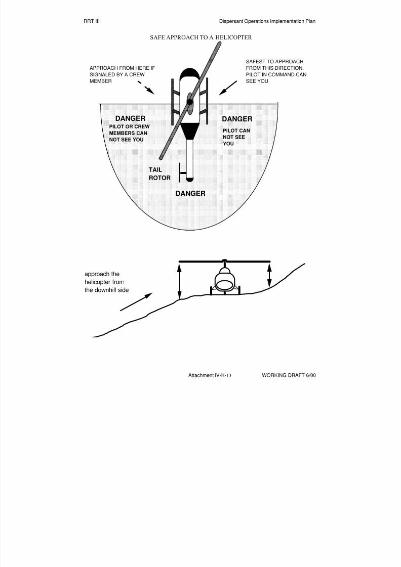
8/3/2019 Guia de selección de tecnologias aplicadas a derrames Vol II
http://slidepdf.com/reader/full/guia-de-seleccion-de-tecnologias-aplicadas-a-derrames-vol-ii 124/298
RRT III Dispersant Operations Implementation Plan
Attachment IV-K-13 WORKING DRAFT 6/00
SAFE APPROACH TO A HELICOPTER
SAFEST TO APPROACH
FROM THIS DIRECTION.
PILOT IN COMMAND CANSEE YOU
DANGER DANGER
DANGER
TAIL
ROTOR
PILOT OR CREW
MEMBERS CAN
NOT SEE YOU
PILOT CAN
NOT SEE
YOU
APPROACH FROM HERE IF
SIGNALED BY A CREWMEMBER
approach the
helicopter from
the downhill side

8/3/2019 Guia de selección de tecnologias aplicadas a derrames Vol II
http://slidepdf.com/reader/full/guia-de-seleccion-de-tecnologias-aplicadas-a-derrames-vol-ii 125/298
RRT III Dispersant Operations Implementation Plan
Attachment IV-K-14 WORKING DRAFT 6/00
GENERIC SITE SAFETY PLAN FOR DISPERSANT OPERATIONS
ATTACHMENT #3
TECHNICAL PRODUCT BULLETIN #D-6
EMERGENCY RESPONSE DIVISIONDATE LISTED: March 10, 1978
"COREXIT 9527"
I. NAME, BRAND, OR TRADEMARK
COREXIT 9527
1. Type of Product: Dispersant (Concentrate)
II. NAME, ADDRESS AND TELEPHONE NUMBER OF MANUFACTURER
Nalco/Exxon Energy Chemicals. LP
P.O. Box 87
Sugar Land, TX 77487-0087
Mr. David Acker, (713)263-7473
Ms. Marge Walsh, (713)263-7265
III. NAME, ADDRESS, AND TELEPHONE NUMBER OF PRIMARY DISTRIBUTORS
Nalco/Exxon Energy Chemicals. LP
P.O. Box 87
Sugar Land, TX 77487-0087
Mr. David Acker, (713)263-7473
Ms. Marge Walsh, (713)263-7265
TO ALERT THE EMERGENCY RESPONSE TEAM CALL 1-800-231-6633 24 HRS/DAY
ASK FOR COREXIT.
IV. SPECIAL HANDLING AND WORKER PRECAUTIONS FOR STORAGE ANDFIELD APPLICATION
1. Flammability:
COREXIT 9527 is not classified as flammable by either DOT or IMO regulations.

8/3/2019 Guia de selección de tecnologias aplicadas a derrames Vol II
http://slidepdf.com/reader/full/guia-de-seleccion-de-tecnologias-aplicadas-a-derrames-vol-ii 126/298
RRT III Dispersant Operations Implementation Plan
Attachment IV-K-15 WORKING DRAFT 6/00
2. Ventilation:
Avoid prolonged breathing of vapors. Use with ventilation equal to unobstructed outdoors in
moderate breeze.
3. Skin and eye contact; protective clothing; treatment in case of contact:
Avoid contact with skin or eyes. The use of gloves, goggles and protective clothing is
recommended. In case of contact, flush exposed area with water. Wash thoroughly after using.
4. Storage temperature:
a. Maximum storage temperature: l70 F
b. Minimum storage temperature: -30 F
c. Optimum storage temperature range: 40 F to l00 F
d. Temperatures of phase separations and chemical changes:
COREXIT 9527 is not adversely affected by changes in storage temperature unless evaporation is
allowed to occur.
V. SHELF LIFE
The shelf life of unopened drums of COREXIT 9527 is unlimited. Containers should always be
capped when not in use to prevent contamination and evaporation of solvents.
VI. RECOMMENDED APPLICATION PROCEDURE
l. Application Method:
The usual application methods are by use of aircraft (COREXIT 9527 is applied undiluted
during aerial spray), hand-held equipment (e.g., spray cans or "back-pack" sprayers) or workboats
(fitted with spray booms mounted ahead of the bow wake as forward as possible.)
COREXIT 9527 should be applied to the floating oil, not to the water around it.
When applied from workboats, an eduction system using a portable fire pump, or a fixed fire-
fighting system is best. This should operate at about 40-80 psi depending on the requirements of
the eductor used, and deliver sea water at a rate adequate to maintain the spray pattern from thenozzles at the operating velocity of the vessel without blowing away before reaching the oil.
Alternatively, the chemical can be fed to the sea water stream with a small metering pump. A
treatment rate of about 5 gallons per acre is recommended. The concentration of chemical
required must be calculated from the pump capacity, the boom swath width, the boat speed, and
(possibly) the thickness of the slick or the amount of oil to be treated over a given area. Unless
land areas are immediately threatened, neither agitation nor chemical concentration should
necessarily be increased simply to cause rapid disappearance of the oil. Nozzles for spray booms

8/3/2019 Guia de selección de tecnologias aplicadas a derrames Vol II
http://slidepdf.com/reader/full/guia-de-seleccion-de-tecnologias-aplicadas-a-derrames-vol-ii 127/298
RRT III Dispersant Operations Implementation Plan
Attachment IV-K-16 WORKING DRAFT 6/00
should produce droplets, not a fog or mist, in a uniform flat spray pattern. Atomizing nozzles are
not recommended.
2. Concentration/Application Rate:
During boat application, using an eductor or metering pump for chemical addition, COREXIT
9527 will usually be added to the sea water stream to give a concentration of 3% to 10%,
depending on the factors given in part 1 of this section.
For slicks formed by more viscous crude or petroleum products, a hydrocarbon based (kerosene
or other aliphatic solvent) dispersant is required. In such a case, one part of COREXIT 9527 may
be diluted with 5 or more parts of solvent.
The required dosage of COREXIT 9527 is usually 3 to 7 gallons per acre, regardless of the
method of application. Undiluted dispersant is always used in aerial spraying.
3. Conditions for Use:
COREXIT 9527 is not recommended for use on spills on fresh water. It can be used most
effectively on spills on salt water of about 1% salt (10,000 ppm salinity) or greater.
Water temperature does not affect the dispersant's action, but the effect of very low temperatures
(in increasing the viscosity of the oil) could make dispersion more difficult.
Weathering of oil can have a negative affect on dispersibility, but the amount of time to reach
that point can vary widely from a few days to more than a month depending on climatic
conditions.
4) VII. TOXICITY AND EFFECTIVENESS
1. TOXICITY:
MATERIAL TESTE SPECIES LC50 (ppm)
COREXIT 9527 Fundulus heteroclitus 100 96-hr
Artemia salina 50 48-hr
No. 2 Fuel Oil Fundulus heteroclitus 4,280 96-hr Artemia salina 44,000 48-hr
COREXIT 9527 & Fundulus heteroclitus 36 96-hr
No. 2 Fuel Oil (1:10) Artemia salina 44 48-hr

8/3/2019 Guia de selección de tecnologias aplicadas a derrames Vol II
http://slidepdf.com/reader/full/guia-de-seleccion-de-tecnologias-aplicadas-a-derrames-vol-ii 128/298
RRT III Dispersant Operations Implementation Plan
Attachment IV-K-17 WORKING DRAFT 6/00
2. EFFECTIVENESS
STANDARD EFFECTIVENESS TEST WITH NO. 6 FUEL OIL
VOLUME INITIAL (10 min) FINAL (2 hrs)
DISPERSANT MEAN % DISPERSION MEAN % DISPERSION
10 71 63
25 69 60
Dosage causing 50% dispersion (from initial dispersion graph) is less than 10 ml.
VIII. MICROBIOLOGICAL ANALYSIS (Not Applicable)
IX. PHYSICAL PROPERTIES
1. Flash Point: 162 F
2. Pour Point: Less than -45 F
3. Viscosity: 60 cst at 60 F, 22 cst at 100 F, 9 cst at 150 F
4. Specific Gravity: 0.995 at 60 F, 0.975 at 100 F
5. pH: 8.2 (10% in de-ionized water)
6. Surface Active Agents: CONFIDENTIAL
7. Solvents: Water, Ethylene glycol monobutyl ether
8. Additives: Borate ester
9. Solubility: Not Applicable
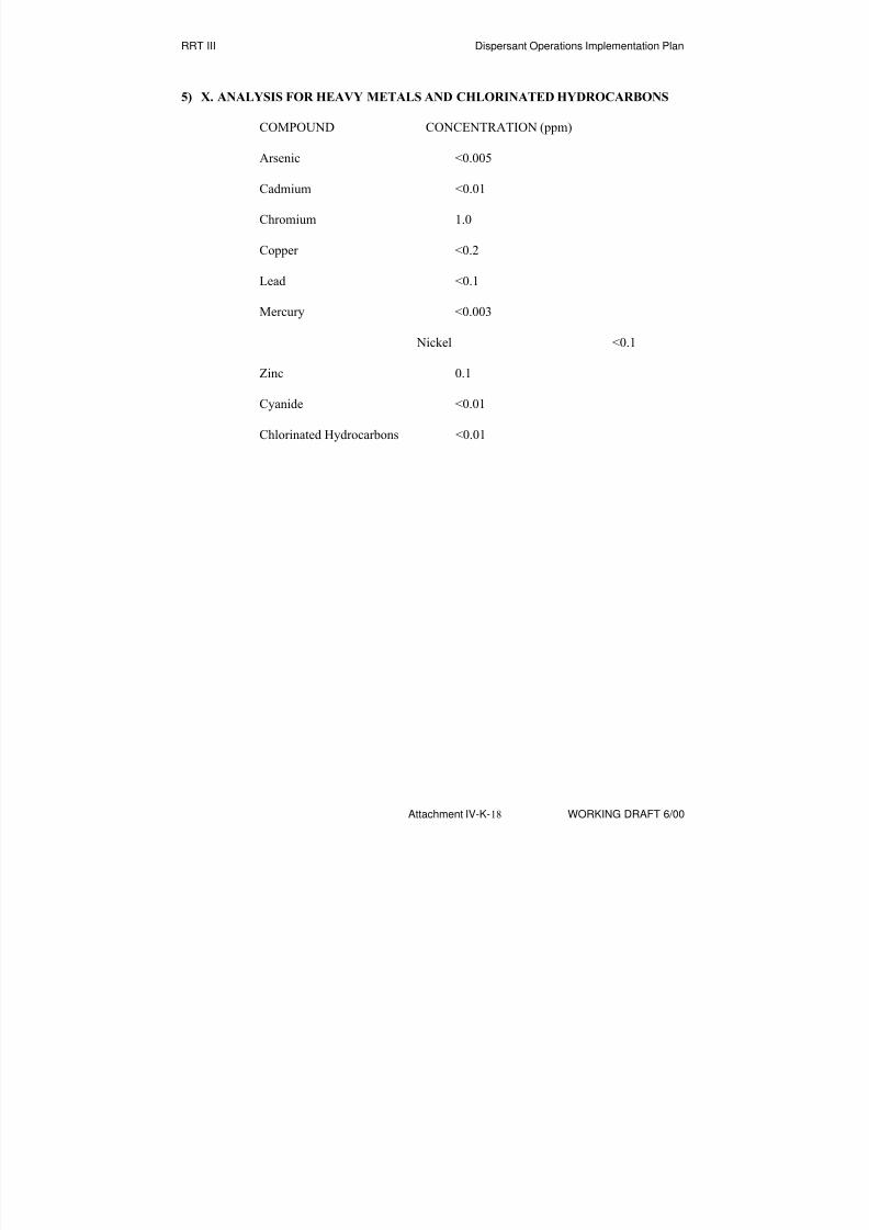
8/3/2019 Guia de selección de tecnologias aplicadas a derrames Vol II
http://slidepdf.com/reader/full/guia-de-seleccion-de-tecnologias-aplicadas-a-derrames-vol-ii 129/298
RRT III Dispersant Operations Implementation Plan
Attachment IV-K-18 WORKING DRAFT 6/00
5) X. ANALYSIS FOR HEAVY METALS AND CHLORINATED HYDROCARBONS
COMPOUND CONCENTRATION (ppm)
Arsenic <0.005
Cadmium <0.01
Chromium 1.0
Copper <0.2
Lead <0.1
Mercury <0.003
Nickel <0.1
Zinc 0.1
Cyanide <0.01
Chlorinated Hydrocarbons <0.01

8/3/2019 Guia de selección de tecnologias aplicadas a derrames Vol II
http://slidepdf.com/reader/full/guia-de-seleccion-de-tecnologias-aplicadas-a-derrames-vol-ii 130/298
RRT III Dispersant Operations Implementation Plan
Attachment IV-K-19 WORKING DRAFT 6/00
GENERIC SITE SAFETY PLAN FOR DISPERSANT OPERATIONS
ATTACHMENT #3 (Cont.)
TECHNICAL PRODUCT BULLETIN #D-69
EMERGENCY RESPONSE DIVISIONDATE LISTED: December 18, 1995
"COREXIT 9500"
I. NAME, BRAND, OR TRADEMARK
COREXIT 9500
1. Type of Product: Dispersant (Concentrate)
II. NAME, ADDRESS AND TELEPHONE NUMBER OF MANUFACTURER
Nalco/Exxon Energy Chemicals. LP
P.O. Box 87
Sugar Land, TX 77487-0087
Phone: (713)263-7256/7265 or (24hrs) 800-231-6633
Fax: (713)263-7955
III. NAME, ADDRESS, AND TELEPHONE NUMBER OF PRIMARY DISTRIBUTORS
Nalco/Exxon Energy Chemicals. LP Nalco/Exxon Energy Chemicals L.P.P.O. Box 87 P.O. Box 220
Sugar Land, TX 77487-0087 Long Beach, CA 90801
Phone: (800) 333-3714 Phone: (310) 639-1533
Nalco/Exxon Energy Chemicals. LP Nalco/Exxon Energy Chemicals L.P.
15555 Poydras Street 701 E. Tudor Street, # 290
New Orleans, LA 70112 Anchorage, AK 99503
Phone: (504) 561-4656 Phone: (907) 563-9866
TO ALERT THE EMERGENCY RESPONSE TEAM CALL 1-800-231-6633 24 HRS/DAY
ASK FOR COREXIT.
8/3/2019 Guia de selección de tecnologias aplicadas a derrames Vol II
http://slidepdf.com/reader/full/guia-de-seleccion-de-tecnologias-aplicadas-a-derrames-vol-ii 131/298
RRT III Dispersant Operations Implementation Plan
Attachment IV-K-20 WORKING DRAFT 6/00
IV. SPECIAL HANDLING AND WORKER PRECAUTIONS FOR STORAGE AND
FIELD APPLICATION
1. Flammability:
COREXIT 9500 is not classified as flammable by either DOT or IMO regulations.
2. Ventilation:
Avoid prolonged breathing of vapors. Use with ventilation equal to unobstructed outdoors in
moderate breeze.
3. Skin and eye contact; protective clothing; treatment in case of contact:
Avoid contact with skin or eyes. The use of gloves, goggles and protective clothing is
recommended. In case of contact, flush exposed area with water. Wash thoroughly after using.
For open systems where contact is likely, wear long sleeve shirt, chemical resistant gloves, andchemical protective goggles.
4. Storage temperature:
a. Maximum storage temperature: l70 F
b. Minimum storage temperature: -30 F
c. Optimum storage temperature range: 40 F to l00 F
d. Temperatures of phase separations and chemical changes: N/A
V. SHELF LIFE
The shelf life of unopened drums of COREXIT 9500 is unlimited. Containers should always be
capped when not in use to prevent contamination and evaporation of solvents.
VI. RECOMMENDED APPLICATION PROCEDURE
l. Application Method:
COREXIT 9500 is a high performance, biodegradable oil spill dispersant concentrate that is
effective on a wide range of oils including the heavier, more weathered oils and emulsified oils.
COREXIT 9500 contains the same surfactants present in COREXIT 9527 and a new improved
oleophilic solvent delivery system. The product can be used in all regions of the world regardlessof climate.
Aerial Spraying. For aerial spraying, apply COREXIT 9500 undiluted. Various fixed-wing
aircraft or helicopters can be used for spraying over a large area, from an altitude of 30 to 50 feet
or even higher, depending on application equipment and aircraft.
The spray nozzles used are most critical since droplet size must be controlled. Avoid nozzles
8/3/2019 Guia de selección de tecnologias aplicadas a derrames Vol II
http://slidepdf.com/reader/full/guia-de-seleccion-de-tecnologias-aplicadas-a-derrames-vol-ii 132/298
RRT III Dispersant Operations Implementation Plan
Attachment IV-K-21 WORKING DRAFT 6/00
that produce too fine a spray (mist or fog). No nozzle may be necessary if the airplane travels at
120 mph (104 knots) or more, since the air shear at these speeds will be sufficient to break the
chemical stream into droplets.
Boat Spraying. COREXIT 9500 may be applied by workboats equipped with spray booms
mounted ahead of the bow wake as far forward as possible. The preferred and most effective
method of application from a workboat is to use a low-volume, low-pressure pump so the
chemical can be applied undiluted. Spray equipment designed to provide a diluted dispersant
solution to the spray booms can also be used. As with most effective concentrates, dispersant
concentrations in the 5 to 10% range are recommended to avoid significant fall-off in
effectiveness. COREXIT 9500 should be applied as droplets, not fogged or atomized. Natural
wave or boat wake action usually provides adequate mixing energy to disperse the oil. Water
from a fire hose can also be used for agitation of the treated slick.
Recent tests have indicated that a slightly modified fire monitor may also be useful for applying
dispersant concentrations such as COREXIT 9500. A screen cap is used on the nozzle of the
monitor to obtain a more uniform spray pattern with the proper sized droplet. Due to the volumeoutput and the greater reach of the fire monitor, significantly more area can be covered in a
shorter period of time than using conventional spray booms.
System Calibration. Spray systems should be calibrated at temperatures anticipated to insure
successful application and dosage control. Application at sub-freezing temperatures may require
larger nozzle, supply lines, and orifices due to higher product viscosity. Refer to Exxon
Chemical Company’s Applications Guide for charts and aids in designing and calibrating
application systems
2. Concentration/Application Rate:
A treatment rate of about 2 to 10 U.S. gallons per acre, or a dispersant to oil ratio of 1:50 to 1:10
is recommended. This rate varies depending on the type of oil, degree of weathering,
temperature, and thickness of the slick.
3. Conditions for Use:
As with any dispersant, COREXIT 9500 should be applied as soon as possible to the floating oil
to ensure the highest degree of success. Early treatment with COREXIT 9500, even at reduced
treat rates, can also counter the “mousse” forming tendencies of the spilled oil.
COREXIT 9500 is useful on oil spills on fresh or salt waters, and at any water temperatures. The product is effective on most oils, weathered spills, and chocolate mousse. Although viscous oil
may require higher dosage rates, any oil that will film or spread on the water surface usually can
be dispersed.

8/3/2019 Guia de selección de tecnologias aplicadas a derrames Vol II
http://slidepdf.com/reader/full/guia-de-seleccion-de-tecnologias-aplicadas-a-derrames-vol-ii 133/298
RRT III Dispersant Operations Implementation Plan
Attachment IV-K-22 WORKING DRAFT 6/00
6) VII. TOXICITY AND EFFECTIVENESS
1. TOXICITY:
MATERIAL TESTED SPECIES LC50 (ppm)
COREXIT 9500 Menidia beryllina 25.20 96-hr
Mysidopsis bahia 32.23 48-hr
No. 2 Fuel Oil Menidia beryllina 10.72 96-hr
Mysidopsis bahia 16.12 48-hr
COREXIT 9500 & Menidia beryllina 2.61 96-hr
No. 2 Fuel Oil (1:10) Mysidopsis bahia 3.4 48-hr
Reference Toxicant Menidia beryllina 7.07 96-hr (SDS) Mysidopsis bahia 9.82 48-hr
2. EFFECTIVENESS
Swirling flask dispersant effectiveness test with South Louisiana and Prudhoe Bay Crude Oils
Oil Effectiveness %
Prudhoe Bay Crude 45.3%
South Louisiana Crude 54.7%
Average of Prudhoe Bay & South Louisiana Crudes 50.0%
VIII. PHYSICAL PROPERTIES
1. Flash Point: 176 F (SETA closed sup; ASTM D3278)
2. Pour Point: -70 F (ASTM D97)
3. Viscosity: 55 cst at 68 F
4. Specific Gravity: 0.949 at 60 F (ASTM D1963)
5. pH: 6.4
6. Chemical Name and Percentage by Weight of the Total Formulation: CONFIDENTIAL

8/3/2019 Guia de selección de tecnologias aplicadas a derrames Vol II
http://slidepdf.com/reader/full/guia-de-seleccion-de-tecnologias-aplicadas-a-derrames-vol-ii 134/298
RRT III Dispersant Operations Implementation Plan
Attachment IV-K-23 WORKING DRAFT 6/00
7. Surface Active Agents: CONFIDENTIAL
8. Solvents: CONFIDENTIAL
9. Additives: None
10. Solubility: Soluble in fresh water, but dispersible in sea water.
7) IX. ANALYSIS FOR HEAVY METALS, CYANIDE, AND CHLORINATED
HYDROCARBONS
COMPOUND CONCENTRATION (ppm)
Arsenic 0.16
Cadmium N/D
Chromium 0.03
Copper 0.10
Lead N/D
Mercury N/D
Nickel N/D
Zinc N/D
Cyanide N/D
Chlorinated Hydrocarbons N/D
N/D = Not Detected

8/3/2019 Guia de selección de tecnologias aplicadas a derrames Vol II
http://slidepdf.com/reader/full/guia-de-seleccion-de-tecnologias-aplicadas-a-derrames-vol-ii 135/298
RRT III Dispersant Operations Implementation Plan
Attachment IV-K-24 WORKING DRAFT 6/00
GENERIC SITE SAFETY PLAN FOR DISPERSANT OPERATIONS
ATTACHMENT #4
PERSONAL PROTECTIVE EQUIPMENT
LEVEL C
OPERATION FOR WHICH THIS LEVEL C ENSEMBLE APPLIES:
Dispersant application, observation and monitoring
SPLASH SUIT
___ Tyvek
___ Saranex
INNER GLOVES
___ Nitrile
OUTER GLOVES
___ Silvershield
___ Solvex
___ Ansol ___ Fireball
OUTER SAFETY BOOTS
___ Neoprene
___ Outer booties
OTHER
___ Full Face Air Purifying Respirator Cartridges: ___________________________
___ Hard Hat
___ EEBA

8/3/2019 Guia de selección de tecnologias aplicadas a derrames Vol II
http://slidepdf.com/reader/full/guia-de-seleccion-de-tecnologias-aplicadas-a-derrames-vol-ii 136/298
RRT III Dispersant Operations Implementation Plan
Attachment IV-K-25 WORKING DRAFT 6/00
LEVEL D
OPERATION FOR WHICH THIS LEVEL D ENSEMBLE APPLIES: _______________
_________________________________________________________________
___ Cloth coveralls
OPTION: long sleeved coveralls (poison plant areas)
OPTION: short sleeved coveralls (heat stress alert)OPTION: street clothing may be worn by personnel not exposed to splashing liquids or oily equipment.
___ rubber steel toe/shank safety boots with textured bottoms
OPTION: hip high rubber boots (e.g., designated snake areas)
OPTION: deck shoes with textured soles (e.g., boat ops)
___ rubber gloves (as needed)
OPTION: leather gloves (if no contact with oil)
___ PFD (all personnel on or near water)
___ quart bottle to carry fluids (during heat stress alerts)
___ hearing protection (in noisy areas)
___ insect repellent (in designated mosquito/tick areas)
___ hard hat (all personnel in designated areas)
___ safety glasses (as required by Site Safety Officer)
OPTION: with tinted lenses (as required for sunlight)
___ sunscreen (as needed for sunlight)
___ whistle (in designated areas)
NOTES:
1) "AS NEEDED" means to use for prevention of significant skin contact with oil.
2) "RUBBER" means chemical resistant material that prevent oil penetration to the skin or cloth
garments underneath.

8/3/2019 Guia de selección de tecnologias aplicadas a derrames Vol II
http://slidepdf.com/reader/full/guia-de-seleccion-de-tecnologias-aplicadas-a-derrames-vol-ii 137/298
RRT III Dispersant Operations Implementation Plan
Attachment IV-K-26 WORKING DRAFT 6/00
This Page Intentionally Left Blank

8/3/2019 Guia de selección de tecnologias aplicadas a derrames Vol II
http://slidepdf.com/reader/full/guia-de-seleccion-de-tecnologias-aplicadas-a-derrames-vol-ii 138/298
RRT III Dispersant Operations Implementation Plan
Attachment VII-A-1 WORKING DRAFT 6/00
DISPERSANT EFFECTIVENESS MONITORING AERIAL CHECKLIST(Completed by Dispersant Op Monitoring Team)
GENERAL:
□ Incident Name: ______________________________________________________
□ Vessel or Facility Name: _______________________________________________
□ Date/Time Spill Occurred: _____________________________________________
□ Location of the Spill: __________________ LAT___________LONG___________
□ Amount/Type of Oil Spilled: ___________________________________________
□ Dispersant Type: _____________________________________________________
OBSERVATIONS:
□ What immediately happened when the dispersant contacted the spill? _________
____________________________________________________________________________
□ After 2 Hours: ________________________________________________________
□ After 6 Hours: ________________________________________________________
□ After 24 Hours (if applicable): ___________________________________________
□ Submerged cloud observed? Yes/No ______________________________________
□ Number of Passes/Sortie: (1)________ (2)_________ (3)_________Total_________
□ Did any oil resurface? Yes/No ___________________________________________
□ Effects On Floating Oil, Biota, Sea Color, Wave Pattern, or Other Physical
Features: ___________________________________________________________________
____________________________________________________________________________ ____________________________________________________________________________
□ Extent of Application/Acres of Oil Sprayed: _______________________________
□ Approximate Percent of Overspray: ______________%

8/3/2019 Guia de selección de tecnologias aplicadas a derrames Vol II
http://slidepdf.com/reader/full/guia-de-seleccion-de-tecnologias-aplicadas-a-derrames-vol-ii 139/298
RRT III Dispersant Operations Implementation Plan
Attachment VII-A-2 WORKING DRAFT 6/00
PHOTOGRAPHY:
□ Color photos taken? Yes/No ___________________________________________
□ Written notes made for photos? Yes/No ___________________________________
□ If videotape of the operation is taken, obtain a copy. _________________________
□ If AIREYE and/or HIRR/IR is used, obtain a copy of the film, tape, or digital
imagery. ______________________________________________________________
□ Monitoring Team Leader reports data to the Scientific Support Coordinator after
each sortie. ____________________________________________________________
THE ABOVE INFORMATION SHOULD BE FILLED OUT FOR EACH SORTIE
MONITORING TEAM LEADER ALSO COMPLETES DEBRIEF SECTION OF THE
PREVIOUS FORM
DISPERSANT GROUP PERSONNEL SHOULD PROVIDE FEEDBACK TO
DISPERSANT OPERATION GROUP SUPERVISOR

8/3/2019 Guia de selección de tecnologias aplicadas a derrames Vol II
http://slidepdf.com/reader/full/guia-de-seleccion-de-tecnologias-aplicadas-a-derrames-vol-ii 140/298
RRT III Dispersant Operations Implementation Plan
Attachment VII-B-1 WORKING DRAFT 6/00
DISPERSANT EFFECTIVENESS MONITORING WATERBORNE
CHECKLIST(Completed by Dispersant Op Monitoring Team)
GENERAL:
□ Incident Name: _________________________________________________________
□ Vessel or Facility Name: _________________________________________________
□ Date/Time Spill Occurred: _______________________________________________
□ Location of the Spill: ____________________ LAT___________LONG___________
□ Amount/Type of Oil Spilled:
□___________________________________________
□ Dispersant Type: _______________________________________________________
FLOUROMETRY / SAMPLING :
□ Monitoring Platform Identified?
Name: ________________________________ Location: ___________________________
ETD: _________________________________ ETA: ___________________ (To Spill Site)
□ Consider: draft, water depth, weather, freeboard, range, speed, transit time, and
completion of each sortie.
□ Take Background Fluorescence Readings
□ Record Transect Readings After the Dispersants are Applied
□ Was an oil/dispersant /water sample collected? Yes ________ No __________
□ If Yes, Label and Record the Following:
□ Geographic Location
□ Depth
□ Location Relative to Spilled Oil
□ Time

8/3/2019 Guia de selección de tecnologias aplicadas a derrames Vol II
http://slidepdf.com/reader/full/guia-de-seleccion-de-tecnologias-aplicadas-a-derrames-vol-ii 141/298
RRT III Dispersant Operations Implementation Plan
Attachment VII-B-2 WORKING DRAFT 6/00
□ Notes: (Why sample was taken? Was it typical or unusual?)
_____________________________________________________________________________
_____________________________________________________________________________
Report Information to Monitoring Team Leader
DEBRIEF:
Did the dispersant operation follow the approved plan? ____________________________
_____________________________________________________________________________
What problems were encountered? ______________________________________________
_____________________________________________________________________________
What recommendations would you make? ________________________________________
_____________________________________________________________________________
DISPERSANT GROUP PERSONNEL SHOULD PROVIDE FEEDBACK TO
DISPERSANT OPERATION GROUP SUPERVISOR

8/3/2019 Guia de selección de tecnologias aplicadas a derrames Vol II
http://slidepdf.com/reader/full/guia-de-seleccion-de-tecnologias-aplicadas-a-derrames-vol-ii 142/298
1 WORKING DRAFT 6/006/30/00
BBIIOORREEMMEEDDIIAATTIIOONN PPLLAANN
Introduction This section of the Selection Guide provides the decision-maker
with the means for evaluating detailed information for individual
strategies and product categories for use when responding to
spilled oil. This document presents details on how an operationusing bioremediation technologies will be carried out, including
organizational assignments.
Purpose An outline of the task to develop an implementation plan for
bioremediation agents is included for the intended purpose and
scope of the plan.
NOTE: The Region IV Bioremediation Plan has been provided in
this Selection Guide as a starting point for Region III’s use. It is
included in this Guide without revisions and is awaiting Region III
revision and comment.

8/3/2019 Guia de selección de tecnologias aplicadas a derrames Vol II
http://slidepdf.com/reader/full/guia-de-seleccion-de-tecnologias-aplicadas-a-derrames-vol-ii 143/298
2
This page intentionally left blank
8/3/2019 Guia de selección de tecnologias aplicadas a derrames Vol II
http://slidepdf.com/reader/full/guia-de-seleccion-de-tecnologias-aplicadas-a-derrames-vol-ii 144/298
REGION IVREGIONAL RESPONSE TEAM
BIOREMEDIATIONSPILL RESPONSE PLAN
AUGUST 1997

8/3/2019 Guia de selección de tecnologias aplicadas a derrames Vol II
http://slidepdf.com/reader/full/guia-de-seleccion-de-tecnologias-aplicadas-a-derrames-vol-ii 145/298
8/3/2019 Guia de selección de tecnologias aplicadas a derrames Vol II
http://slidepdf.com/reader/full/guia-de-seleccion-de-tecnologias-aplicadas-a-derrames-vol-ii 146/298
i
TABLE OF CONTENTS
INTRODUCTION.............................................................................................................1
PURPOSE.......................................................................................................................1
APPLICABLE REGULATIONS........................................................................................2
ROLES AND RESPONSIBILITIES..................................................................................2On-Scene Coordinator (OSC)...............................................................................2Federal Agencies..................................................................................................3
US Environmental Protection Agency........................................................3US Coast Guard.........................................................................................3National Oceanographic and Atmospheric Administration.........................3Department of Interior ................................................................................3
State and Local Agencies.....................................................................................3Responsible Parties..............................................................................................4
DECISION TOOLS..........................................................................................................4Decision Process ..................................................................................................4Bioremediation Use Authorization Form...............................................................4
FEASIBILITY ASSESSMENT CRITERIA........................................................................6Incident Characteristics ........................................................................................6Characteristics of Spilled Oil .................................................................................6
Group I: Very Light Refined Products ........................................................6Group II: Diesel-like Products and Light Crude Oils...................................7Group III: Medium-grade Crude Oils and Intermediate Products............... 7Group IV: Heavy Crude Oils and Residual Products..................................7Group V: Very Heavy Residual Products ...................................................7
Characteristics of Affected Habitats......................................................................8Open Water, Off-shore, Tidal Inlets and Water Intakes.............................8Small Ponds, Lakes, Rivers and Streams..................................................8Solid Man-Made Structures: Exposed and Sheltered ................................9Exposed Scarps in Clay and Wave-Cut Clay Platforms.............................9Fine-grained Sand Beaches or Sandy Banks ............................................9Mixed Sand and Shell Beaches and Shell Beaches or Banks ...................9Riprap: Exposed and Sheltered.................................................................9Exposed Tidal Flats and Sheltered Tidal Flats...........................................9Salt to Brackish-water Marshes, Freshwater Marshes, Freshwater
Swamps and Mangroves...............................................................10
LOGISTICAL CONCERNS............................................................................................10Scale of Bioremediation Response.....................................................................10Agent Availability ................................................................................................10

8/3/2019 Guia de selección de tecnologias aplicadas a derrames Vol II
http://slidepdf.com/reader/full/guia-de-seleccion-de-tecnologias-aplicadas-a-derrames-vol-ii 147/298
ii
Application and Monitoring Resources ...............................................................11
IMPLEMENTATION.......................................................................................................11RRT Notification..................................................................................................11Bioremediation work plan ...................................................................................12
Organization.............................................................................................13Tactics and assignments .........................................................................13Supporting Material..................................................................................14
Public Safety/Information ..............................................................14Site/Worker Safety ........................................................................14
Biomonitoring plan..............................................................................................15Objectives ................................................................................................15Quality Assurance....................................................................................16Biomonitoring Plan Design.......................................................................16Monitoring Activities .................................................................................17
Untreated areas.............................................................................17Treated area..................................................................................18
Documentation and reporting .............................................................................19Activity reports..........................................................................................19Analytical reports......................................................................................20
Plan revision .......................................................................................................20
APPENDIX A. APPLICABLE FEDERAL AND STATE REGULATIONS.......................22Federal Regulations............................................................................................22State Regulations and Policies ...........................................................................23Regulations and Policies in the State of Florida .................................................23Regulations and Policies in the State of North Carolina .....................................24
APPENDIX B. BIOREMEDIATION USE AUTHORIZATION FORM............................26Incident Characteristics ......................................................................................26Feasibility Assessment Criteria...........................................................................27Bioremediation Work plan ..................................................................................28Biomonitoring Plan..............................................................................................28Project Management...........................................................................................28
APPENDIX C. EVALUATING BIODEGRADATION POTENTIAL OF VARIOUS OILS 29
APPENDIX D. BIOREMEDIATION AGENTS AND AGENT SELECTION....................30
Background.........................................................................................................30Types of Agents..................................................................................................31
Microbial Agents.......................................................................................31Nutrients...................................................................................................31Enzymatic ................................................................................................31Other Agent..............................................................................................31Agent Evaluation Procedure ....................................................................32Base Tier -- "Go"/"No Go". Requirements and Information.....................32

8/3/2019 Guia de selección de tecnologias aplicadas a derrames Vol II
http://slidepdf.com/reader/full/guia-de-seleccion-de-tecnologias-aplicadas-a-derrames-vol-ii 148/298
iii
Tier I -- Feasibility Assessment................................................................33Tier II - Laboratory-Scale Data.................................................................33Tier Ill - Simulated Field Test Demonstration ...........................................34Tier IV -- Limited Field-Scale Demonstration of the Agent.......................34
Agent Selection...................................................................................................35
APPENDIX E. LABORATORY ANALYSIS PARAMETERS .........................................36
APPENDIX F. INFORMATION FEEDBACK: BIOREMEDIATION USE FOLLOW-UPFORM .................................................................................................................38
APPENDIX G. REFERENCES.....................................................................................41
TABLES AND DIAGRAMS
DIAGRAM 1. BIOREMEDIATION DECISION TREE. .............................5
TABLE 1. FIELD MONITORING PARAMETERS..................................21
TABLE 2. LABORATORY ANALYSIS PARAMETERS..........................36

8/3/2019 Guia de selección de tecnologias aplicadas a derrames Vol II
http://slidepdf.com/reader/full/guia-de-seleccion-de-tecnologias-aplicadas-a-derrames-vol-ii 149/298
1
INTRODUCTION Biodegradation is a natural process in which microorganisms chemically alter andbreakdown organic molecules into other substances - such as fatty acids, carbondioxide and water - in order to obtain energy and nutrients. The basis for this process is
relatively simple: microorganisms require minerals and sources of carbon, as well aswater and other elements, to survive and function. The process can involve one step ora series of steps that proceed through the formation of molecules with successivelyfewer carbons. Generally, the extent to which a particular organic molecule isbiodegradable and the rate of degradation depend on the molecule's structuralcharacteristics (chain length, amount of branching, number and arrangement of rings,stereochemistry) and the environmental conditions (temperature, available oxygen,substrate).
Bioremediation is a treatment technology that utilizes biodegradation to reduce theconcentration and/or toxicity of chemical substances such as petroleum products andother hydrocarbons. Because microbes capable of degrading hydrocarbons arecommonly found in nature, most untreated hydrocarbon spills eventually are removedfrom the environment by microbial degradation and other processes. Enhancedbioremediation, however, seeks to accelerate natural biodegradation processes byapplying specially chosen nutrients and/or microbes to spilled substances. Althoughmicrobes have been used extensively and successfully for many years to treat wastesand wastewater in controlled facilities, their potential as a tool for responding to spills ofoil and hazardous substances in uncontrolled environments has only more recentlyreceived significant interest. (For additional information on bioremediation, refer toAppendix G.)
This document presents a plan for considering and implementing bioremediation,through either natural attenuation or nutrient/microbe enhancement, as a supplementalresponse tool for spills in US Environmental Protection Agency (EPA) Region 4. It wasdeveloped through the coordinated efforts of EPA's Subcommittee on NationalBioremediation Spill Response and the members of the Region 4 Regional ResponseTeam (RRT), using EPA's Interim Guidelines for Preparing Bioremediation SpillResponse Plans.
PURPOSE
This document has a threefold purpose:
To outline a process by which Federal On-Scene Coordinators (OSCs) in Region4 may request authorization to use bioremediation in response to spills of oil orhazardous substances (the authorization procedures presented are consistentwith the National Oil and Hazardous Substances Pollution Contingency Plan(NCP));

8/3/2019 Guia de selección de tecnologias aplicadas a derrames Vol II
http://slidepdf.com/reader/full/guia-de-seleccion-de-tecnologias-aplicadas-a-derrames-vol-ii 150/298
2
To define the types of information necessary to determine if bioremediation isfeasible, provide as much of this information in advance as possible, and outlinea mechanism for capturing information on bioremediation use for future decisionmaking; and,
To describe how to implement a bioremediation activity and determine ifbioremediation is working.
The document is intended to guide decision makers in evaluating the appropriatenessof bioremediation in the cleanup strategy for a spill and in undertaking a bioremediationactivity. Ultimately, decisions regarding the use of bioremediation must be based onthe OSC's best judgment given the particular circumstances of the spill incident.
The RRT's Response Technology Committee will examine, on an as needed basis, theinformation in this plan, consider any new advances in and additional experience withbioremediation, and revise the plan as appropriate. Recommendations for revisionsshould be submitted to the Region 4 RRT for approval. Upon, approval by the RRT,revisions should be incorporated into the Region 4 RCP and other local plans, asappropriate.
APPLICABLE REGULATIONS Legislation at both the federal and state level may affect decisions to usebioremediation. Existing regulations and policies that govern the use of bioremediationagents in response to spills in Region 4 are summarized in Appendix A.
ROLES AND RESPONSIBILITIES This section discusses issues relevant to managing the response to a spill, withparticular emphasis to managing bioremediation activities.
On-Scene Coordinator (OSC)
As per 40 CFR Section 300.120, USCG and EPA provide pre-designated OSCs thathave overall responsibility for oil spill responses in the coastal and inland zonesrespectively. When considering or actually using bioremediation as a response tool,the OSC shall be responsible for ensuring that the requirements set forth in this planare properly followed and implemented. This includes notification, planning,documentation and monitoring of all bioremediation activities. Thus, the OSC, inconjunction with his/her contractors or a responsible party, will be directly involved inthe cleanup effort.

8/3/2019 Guia de selección de tecnologias aplicadas a derrames Vol II
http://slidepdf.com/reader/full/guia-de-seleccion-de-tecnologias-aplicadas-a-derrames-vol-ii 151/298
3
Federal Agencies US Environmental Protection Agency - EPA, with their extensive technical expertise inbioremediation, may lend themselves to the OSC as a technical advisor. This expertiseincludes information on the ability of various bioremediation treatment techniques to
degrade oil, their relative toxicity to a habitat and the expected rate of degradation.Typically, EPA provides the Scientific Support Coordinator for inland zone spills. Inaddition, EPA maintains laboratory facilities that may be used to run bioremediationrelated studies and analyses.
US Coast Guard - The USCG supplies expertise in oil spill response technology andincident command. Response support, through manpower or equipment, can beprovided by the Strike Teams and the National Strike Force Coordination Center.Additionally, the USCG can assist with cost tracking and funding support from the OilPollution Trust Fund.
National Oceanographic and Atmospheric Administration - NOAA/HAZMAT providesScientific Support Coordinators (SSCs) and their support teams. The SSC providesscientific advice to support the Federal OSCs in operational decisions that will protectthe environment effectively, mitigate collateral harm, and facilitate environmentalrecovery. The NOAA/HAZMAT Scientific Support Team has extensive expertise in allscientific aspects of spill response and mitigation and vast experience with oil spillresponse and several applications of bioremediation in both operational andexperimental use. Their expertise in biology, geomorphology, chemistry, and physicaland coastal processes and their support can assist in the appropriate selection ofbioremediation as a response technique and in its proper application. NOAA/HAZMATalso provides the Department of Commerce RRT member. The DOC RRT memberprovides advice and access to NOAA and DOC resources and expertise and serves asthe point of contact for DOC/NOAA trustee issues.
Department of Interior - DOI has direct jurisdiction for the protection of resources on itsown lands, as well as trustee responsibilities for certain natural resources, regardless oflocation. They can provide information concerning the lands and resources related togeology, hydrology, minerals, fish and wildlife, cultural resources and recreationresources. The DOI natural resource trusteeship also includes migratory birds,anadromous fish and endangered or threatened species and their critical habitats.
State and Local Agencies
State and local agencies have a distinct role and perspective during a response thatimpacts their own resources. Typically, these agencies can provide valuableinformation on the latest regulations, guidelines, water resource conditions,environmentally sensitive areas and public concerns. Therefore, any response effortshould be carefully coordinated with impacted State and local agencies.

8/3/2019 Guia de selección de tecnologias aplicadas a derrames Vol II
http://slidepdf.com/reader/full/guia-de-seleccion-de-tecnologias-aplicadas-a-derrames-vol-ii 152/298
4
Responsible Parties
Since the RP has firsthand information concerning the spilled material, the RP mayrequest OSC approval for the use of bioremediation or the application of a
bioremediation enhancing agent. The RP can initiate a bioremediation activity after therequest is approved by the OSC following concurrence from RRT 4 and consultationwith the impacted natural resource trustees. The OSC's request, on behalf of the RP,shall be accompanied by a completed Bioremediation Use Authorization Form.Maximum cooperation and participation should be expected from the RP throughout theentire response and bioremediation activity.
DECISION TOOLS Spills may be good candidates for bioremediation treatment based on characteristics ofthe spill and environmental sensitivities of the spill location. To assist OSCs and theRRT in evaluating spills for bioremediation treatment and to document the basis forresponse decision making, the following are provided: (1) a diagram outlining thedecision process that OSCs should follow when deciding whether to usebioremediation, and (2) a form for obtaining authorization to use bioremediation thatspecifies information which should be collected for presentation to the OSC and RRT.This form, the Bioremediation Use Authorization Form, is presented in Appendix B.
Decision Process
Decisions to use bioremediation should be made after applicable regulatory policies,potential environmental impacts, operational feasibility, logistical coordination, and otherpertinent issues have been evaluated. The process to determine whetherbioremediation may be feasible for a particular spill is illustrated in Diagram 1. Detailsfor addressing the specific issues are outlined in the section Feasibility AssessmentCriteria.
Bioremediation Use Authorization Form
A Bioremediation Use Authorization Form that specifies the minimum informationrequirements necessary to support decisions regarding the use of bioremediation isincluded in Appendix B of this plan. The form requests details of the spill incident,bioremediation details, bioremediation Work plan and monitoring plan. Once the formhas been completed, it should provide pertinent information needed to make a decisionregarding the use of bioremediation.
A completed authorization form should be transmitted to the RRT for the requiredauthorization to proceed with bioremediation treatment. The RRT shall approve ordisapprove the use of bioremediation within 24 hours of receiving a completed formfrom an OSC.
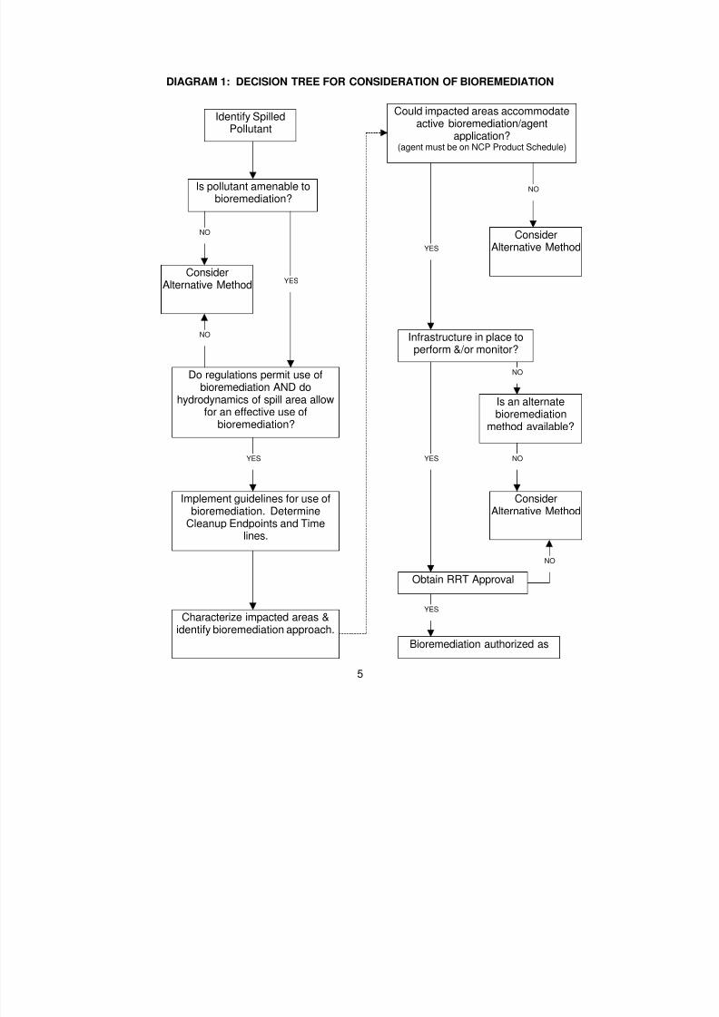
8/3/2019 Guia de selección de tecnologias aplicadas a derrames Vol II
http://slidepdf.com/reader/full/guia-de-seleccion-de-tecnologias-aplicadas-a-derrames-vol-ii 153/298
5
DIAGRAM 1: DECISION TREE FOR CONSIDERATION OF BIOREMEDIATION
Identify SpilledPollutant
Is pollutant amenable tobioremediation?
ConsiderAlternative Method
Do regulations permit use ofbioremediation AND do
hydrodynamics of spill area allow
for an effective use ofbioremediation?
Implement guidelines for use ofbioremediation. Determine
Cleanup Endpoints and Timelines.
Characterize impacted areas &identify bioremediation approach.
Could impacted areas accommodateactive bioremediation/agent
application?(agent must be on NCP Product Schedule)
ConsiderAlternative Method
Infrastructure in place toperform &/or monitor?
Is an alternate
bioremediationmethod available?
ConsiderAlternative Method
Obtain RRT Approval
Bioremediation authorized as
YES
YES
YESYES
YES
NO
NO
NO
NO
NO
NO

8/3/2019 Guia de selección de tecnologias aplicadas a derrames Vol II
http://slidepdf.com/reader/full/guia-de-seleccion-de-tecnologias-aplicadas-a-derrames-vol-ii 154/298

8/3/2019 Guia de selección de tecnologias aplicadas a derrames Vol II
http://slidepdf.com/reader/full/guia-de-seleccion-de-tecnologias-aplicadas-a-derrames-vol-ii 155/298
7
Group II: Diesel-like Products and Light Crude Oils (no.2 jet fuel oil, jet fuel,kerosene, marine diesel, West Texas Crude, Alberta Crude)
C moderately volatile; persists in environment for an increasing period oftime as A weight @ of material increases
C light fractions will evaporate to no residueC crude oils leave residue after evaporationC moderate to high toxicity to biotaC can form stable emulsionsC tend to penetrate substrate; fresh spills are not adhesiveC specific gravity of 0.80-0.85; API gravity of 35-45C bioremediation most effective on lower molecular weight oils, with
faster degrading components; aromatic portions less susceptible todegradation
Group III: Medium-grade Crude Oils and Intermediate Products (North
Slope crude, South Louisiana crude, no. 4 fuel oil, lube oils) C moderately volatileC up to one third will evaporate in the first 24 hoursC moderate to high viscosityC specific gravity of 0.85-0.95; API gravity of 17.5-35C variable acute toxicity, depending on amount of light fractionC can form stable emulsionsC variable substrate penetration and adhesionC bioremediation most effective on lower molecular weight oils, with
faster degrading components
Group IV: Heavy Crude Oils and Residual Products (Venezuela crude, San Joaquin Valley crude, Bunker C, no. 6 fuel oil)C slightly volatileC very little product loss by evaporationC very viscous to semisolid; may become less viscous when warmedC specific gravity of 0.95-1.00; API gravity of 10-17.5C low acute toxicity relative to other oil typesC can form stable emulsionsC little substrate penetration; can be highly adhesive++++ higher molecular weight and fewer number of straight-chained
hydrocarbons makes bioremediation less effective than on medium
oils
Group V: Very Heavy Residual Products C very similar to all properties of Group IV oils, except that the specific
gravity of the oil is greater than 1.0 (API gravity less than 10). Thus, theoil has greater potential to sink when spilled.

8/3/2019 Guia de selección de tecnologias aplicadas a derrames Vol II
http://slidepdf.com/reader/full/guia-de-seleccion-de-tecnologias-aplicadas-a-derrames-vol-ii 156/298
8
Characteristics of Affected Habitats After evaluating the spilled oil's susceptibility to biodegradation, the habitats
impacted by the spilled contaminant and the background level of nutrients in theimpacted area should be identified and characterized. For each of the following
habitats, the recommended approach is provided; O for Optional , NA for Not Advisable .[NOTE: NA does not preclude the OSC from conducting a Pilot Test to determine theeffectiveness of bioremediation in an area. The harmful effects of the oil must bebalanced against the potential effects of bioremediation.] The listed habitats areappropriate for marine, estuarine and riverine settings.
Open Water (NA) Off-shore Waters (NA)
Tidal Inlets (NA) Water Intakes (NA)
Small Lakes/Ponds (NA) Small Rivers/Streams (NA)
Exposed Man-made Structures (NA) Sheltered Man-made (NA)Structures
Exposed Scarps in Clay (O) Wave-cut Clay Platforms (O)
Fine-grained Sand Beaches (O) Sandy Banks (O)
Mixed Sand and Shell Beaches (O) Shell Beaches or Banks (O)
Exposed Rip-rap (O) Sheltered Rip-rap (O)
Exposed Tidal Flats (NA) Sheltered Tidal Flats (NA)
Salt to Brackish-water Marshes (O) Freshwater Marshes (O)
Freshwater Swamps (O) Mangroves (O)
Open Water, Off-shore, Tidal Inlets and Water Intakes NA
Bioremediation is not effective for the time-frames of concern, relative tothe potential of transport of the oil to areas where it could affect moresensitive resources. Thus, bioremediation treatment is not advisable forthese habitats or areas.
Small Ponds, Lakes, Rivers and Streams NA
Not applicable for gasoline and light oils due to their rapid evaporation.There is insufficient information on impacts and effectiveness for other oil
types, however there are special concerns about nutrient overloading insmall, restricted water bodies.

8/3/2019 Guia de selección de tecnologias aplicadas a derrames Vol II
http://slidepdf.com/reader/full/guia-de-seleccion-de-tecnologias-aplicadas-a-derrames-vol-ii 157/298
9
Solid Man-Made Structures: Exposed and Sheltered NA
Oiling of exposed sea walls usually occurs as a band at the high-tide line.
This type of oiling is not amenable to bioremediation because of difficultyof application and low effectiveness.
Exposed Scarps in Clay and Wave-Cut Clay Platforms O
Because of their erosional nature, removal of lightly oiled sediments maynot be recommended on these habitats. Bioremediation may be an optionwhereby the oil could be treated in place.
Fine-grained Sand Beaches or Sandy Banks O
On outer beaches with low recreational use, bioremediation may be anoption, particularly for light oiling or residual oil left after othercountermeasures have been completed.
Fine-grained sand beaches also occur along bay margins and dredgespoil banks. Sandy banks occur along rivers. These habitats typicallyoccur in more sheltered areas, where natural removal of residual oil bywave or current action will be slower then along exposed beaches. Theyare often not amenable to mechanical removal, thus manual removal ofheavy accumulations of oil or oiled wrack may be conducted.Bioremediation may be considered for sites with light oiling or residual oil
left after manual removal efforts have been terminated.
Mixed Sand and Shell Beaches and Shell Beaches or Banks O
For lightly or moderately oiled beaches and banks, particularly wheremechanical cleanup may result in removal of large amounts of sedimentor be logistically difficult, bioremediation or Ano action@ may beconsidered. This option is best considered for sites without significantrecreational use.
Riprap Exposed and Sheltered O
Oil on riprap can occur as a coating on the boulders or as persistentaccumulations of oil in the void spaces between the boulders. Neithertype of oil is amenable to effective removal by bioremediation techniquesunder most conditions. Thus, bioremediation treatment would be optional.

8/3/2019 Guia de selección de tecnologias aplicadas a derrames Vol II
http://slidepdf.com/reader/full/guia-de-seleccion-de-tecnologias-aplicadas-a-derrames-vol-ii 158/298
10
Exposed Tidal Flats and Sheltered Tidal Flats NA
Both of these habitats are inundated daily by high tides which results inrapid dilution and flushing of applied nutrients. Bioremediation is not likely
to be effective under these conditions. There are significant toxicityconcerns for use of bioremediation agents in shallow, poorly flushedareas, such as sheltered tidal flats, or subtidal habitats where there areconcentrations of sensitive life stages of fish and shellfish, such as seagrass beds and oyster reefs.
Salt to Brackish-water Marshes, Freshwater Marshes, Freshwater Swamps
and Mangroves O
There are very few cleanup options which do not cause significantimpacts to these sensitive habitats. Most often, Ano action@ is the
preferred option. However, there may be conditions under whichbioremediation may be considered, particularly for lighter oils. In wetlandswith shallow, poorly mixed water bodies, the potential increase ineutrophication and ammonia caused by aggressive bioremediation needsto be considered.
LOGISTICAL CONCERNS
Characteristics of a spill incident, including characteristics of affected habitats
and spilled pollutant, should determine whether a spill is a candidate for bioremediationtreatment. If, based on these factors bioremediation has not been eliminated as aresponse alternative, then the logistical feasibility of implementing an appropriatebioremediation action plan should be evaluated. Implementation considerations includethe proposed scale of a bioremediation activity, the availability of the bioremediationagent(s) proposed for application (if used), and the availability of the resourcesnecessary to conduct the application and monitoring recommended for the agent(s)proposed for use in each affected habitat. (The latter two considerations are highlydependent on the first.)
Scale of Bioremediation Response
The first step in assessing the logistical feasibility of bioremediation is todetermine the scale of the bioremediation response. The scale of the bioremediationresponse refers to the extent to which bioremediation will be involved in the cleanup,particularly in terms of the size of the area. The scale of the bioremediation responseeffort will determine the amount of agent(s) (if any), the number of personnel, and theequipment resources necessary to complete the chosen treatment technique andmonitoring of the bioremediation response effort.
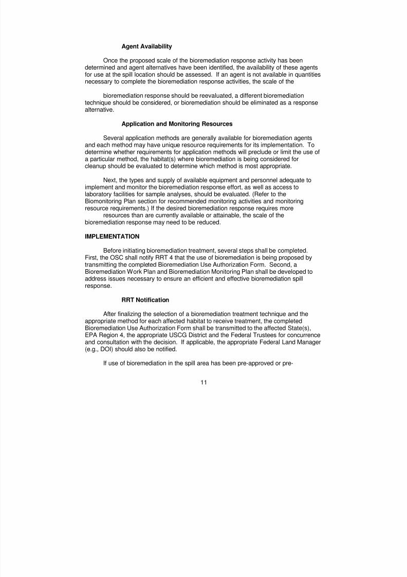
8/3/2019 Guia de selección de tecnologias aplicadas a derrames Vol II
http://slidepdf.com/reader/full/guia-de-seleccion-de-tecnologias-aplicadas-a-derrames-vol-ii 159/298
11
Agent Availability
Once the proposed scale of the bioremediation response activity has beendetermined and agent alternatives have been identified, the availability of these agents
for use at the spill location should be assessed. If an agent is not available in quantitiesnecessary to complete the bioremediation response activities, the scale of the
bioremediation response should be reevaluated, a different bioremediationtechnique should be considered, or bioremediation should be eliminated as a responsealternative.
Application and Monitoring Resources
Several application methods are generally available for bioremediation agentsand each method may have unique resource requirements for its implementation. Todetermine whether requirements for application methods will preclude or limit the use ofa particular method, the habitat(s) where bioremediation is being considered forcleanup should be evaluated to determine which method is most appropriate.
Next, the types and supply of available equipment and personnel adequate toimplement and monitor the bioremediation response effort, as well as access tolaboratory facilities for sample analyses, should be evaluated. (Refer to theBiomonitoring Plan section for recommended monitoring activities and monitoringresource requirements.) If the desired bioremediation response requires more
resources than are currently available or attainable, the scale of thebioremediation response may need to be reduced.
IMPLEMENTATION
Before initiating bioremediation treatment, several steps shall be completed.First, the OSC shall notify RRT 4 that the use of bioremediation is being proposed bytransmitting the completed Bioremediation Use Authorization Form. Second, aBioremediation Work Plan and Bioremediation Monitoring Plan shall be developed toaddress issues necessary to ensure an efficient and effective bioremediation spillresponse.
RRT Notification
After finalizing the selection of a bioremediation treatment technique and theappropriate method for each affected habitat to receive treatment, the completedBioremediation Use Authorization Form shall be transmitted to the affected State(s),EPA Region 4, the appropriate USCG District and the Federal Trustees for concurrenceand consultation with the decision. If applicable, the appropriate Federal Land Manager(e.g., DOI) should also be notified.
If use of bioremediation in the spill area has been pre-approved or pre-

8/3/2019 Guia de selección de tecnologias aplicadas a derrames Vol II
http://slidepdf.com/reader/full/guia-de-seleccion-de-tecnologias-aplicadas-a-derrames-vol-ii 160/298
12
authorized by RRT 4, this concurrence is not necessary. However, the OSC must stillnotify RRT 4 of the decision to use bioremediation. In the event RRT 4 pre-authorizesan area for the use of bioremediation, such areas will be included in the plan byaddendum.
BIOREMEDIATION WORK PLAN
Work plans are important to ensure the safe, coordinated, and well documentedimplementation of bioremediation. Work plans are comprised of systematic proceduresand guidelines that clarify and resolve issues such as worker and public safety,documentation requirements, response personnel roles and responsibilities, treatmenttechnique agent application protocols, and application control and oversightconsiderations. Complete Work plans must include spill and site specificconsiderations. It is essential in a response that every incident or event be managedaccording to a plan and bioremediation is no exception. The Work plan shall provide:
Ë A clear statement of objectives and actions.Ë A basis for-measuring work effectiveness and cost effectiveness.Ë A basis for measuring work progress and for providing accountability.
Plans should be prepared for specific time periods or operational periods. Theseperiods can be of various segments of time. Decisions on the length of the operationalperiod or time segments may be affected by the length of time available/needed toachieve objectives, the availability of resources, environmental considerations, andsafety considerations. Essential parts of any Work plan are:
1. Statement of objectives - Statement of what is expected to be achieved.Objectives must be measurable.
2. Organization - Describes what organization will be in place. This willdescribe in detail the specific roles and responsibilities of the participantsin a bioremediation treatment technique. This will also describe theinteraction of one entity to another.
3. Tactics and assignments - Describes tactics and control operations andwhat resources will be assigned. If the application is a large one,resource assignments may be done by groups.
4. Supporting material - Examples include a map or sketch of the area(s)to be treated, communications, traffic plan, weather data, specialprecautions, and safety information.
All supervisory personnel must be familiar with the plan and any changes whichdevelop throughout the life of the project. This can be accomplished through briefingsand by distributing copies of the written plan.

8/3/2019 Guia de selección de tecnologias aplicadas a derrames Vol II
http://slidepdf.com/reader/full/guia-de-seleccion-de-tecnologias-aplicadas-a-derrames-vol-ii 161/298
13
The Work plan must include an avenue to provide for ongoing evaluation of theplan's effectiveness. Supervisors should regularly assess work progress against controloperations called for in the plan. If deficiencies are found, improved direction oradditional staffing may be required, tactical operations may need to be modified, and/orchanges may need to be reflected in planning for the next segment of time.
Demobilization activities, although often overlooked, are an integral part of theWork plan. As the project begins to wind down, everyone will be anxious to leave thescene and return home. Demobilization planning helps to assure a controlled, safe,efficient, and cost effective demobilization process.
Organization
The response structure or organizational framework identifies the participants ina response, their general areas of responsibility, and the lines of authority among them.A chart illustrating the participants in a bioremediation response activity in Region 4
and their inter-relationships would be very helpful in summarizing this information. Indeveloping this section, the following questions should be addressed:
Ë Who will manage the overall bioremediation activity?Ë Who will be the likely participants (e.g. federal and state agencies)
in the activity for the Region? What are the general roles?Ë Who will be the likely participants, if any, from outside the Region?
What are the general roles?Ë Who will manage the monitoring portions of the activity?Ë Who will develop an appropriate Work plan for the bioremediation
activity?Ë Who will perform specific treatment method or agent(s)
application(s)?Ë Who will perform monitoring?Ë Who will perform public outreach?
Describe in detail the specific roles and responsibilities of the likely participants(RRT, federal and state agencies, international governments/agencies,non-governmental organizations, responsible parties, etc.) in a bioremediation activity inRegion 4. The information in this section should coincide with the informationpresented above on the regional response structure.
Tactics and assignments
Tactical direction includes determining the tactics and operations necessary forthe selected strategy and determining and assigning the appropriate resources.
Resource assignments should be made for each specific work task. Suchassignments should consists of the kind, types and numbers of resources available andneeded to achieve the desired outcomes.

8/3/2019 Guia de selección de tecnologias aplicadas a derrames Vol II
http://slidepdf.com/reader/full/guia-de-seleccion-de-tecnologias-aplicadas-a-derrames-vol-ii 162/298
14
Personnel and logistical support factors must be considered in determiningtactical operations. Lack of logistical support can mean the difference between successand failure in achieving objectives.
Supporting Material
Public Safety/Information - Public safety is paramount in anybioremediation project. The following are some suggested actions which should betaken during a spill response to ensure public awareness and protection:
Provide news releases and updates to newspapers, radio,television stations, and neighboring areas that couldpotentially be impacted by bioremediation activities. Beprepared to discuss details regarding the chosen treatmenttechnique in simple lay terms so the affected public will havean understanding of exactly what to expect and what theexpected benefits are.
Site/Worker Safety- Worker health and safety is always the foremostconcern during any spill response action. Since all oil spill response actions require ahealth and safety plan and the bioremediation application is merely a facet of the totalspill response effort, the existing heath and safety plan should be used for thebioremediation application and augmented with the specific safety hazards associatedwith the bioremediation treatment method or agent application. A section referred to asbiological hazards should be included in all health and safety plans associated with oilspill responses where biological agents are used as a response tool. This sectionshould discuss the specific health and safety concerns associated with possibleexposure to biological agents and include material safety data sheets (MSDS) for allagents being used. At a minimum, the health and safety plan should address thefollowing aspects of the bioremediation treatment method/monitoring program:
1. minimum health and safety concerns,2. potential hazards during application and monitoring,3. evaluations of those identified hazards,4. actions described to minimize the potential hazards, and5. response(s) needed if hazard does effect worker(s).
The following documents contain guidance on the preparation of health andsafety plans:
1. OSHA 1910.120 and EPA 40 CFR 311,2. USEPA, OERR ERT Standard Operating Procedures,3. NIOSH/OSHA/USCG/EPA Occupational Health and Safety Guidelines,4. ACGIH Threshold Limit Values, and5. existing local and area contingency plans.

8/3/2019 Guia de selección de tecnologias aplicadas a derrames Vol II
http://slidepdf.com/reader/full/guia-de-seleccion-de-tecnologias-aplicadas-a-derrames-vol-ii 163/298
15
To avoid disturbances to the treated area after treatment, all treated and controlsites should be secured by the best achievable means. To avoid possible injury, postwarning signs or secure the treated area to differentiate the site from surroundinglocalities.
BIOMONITORING PLAN
Bioremediation is assumed to enhance the biodegradation of oil or hazardoussubstances without increasing adverse impacts to human or ecological health. Untilthere is defensible documentation from actual field use to confirm this assumption,however, bioremediation effectiveness and safety need to be monitored through asound program of applied science. Therefore, an associated biomonitoring programshall be conducted when bioremediation treatment (either natural or enhanced) is usedas a response tool. The plan outlining the biomonitoring program will be referred to asthe biomonitoring plan.
Objectives
The principal objectives of the monitoring program and the elements of eachobjective are listed below.
1. Determine the efficacy of the selected bioremediation treatment methodas it relates to the degradation of the spilled material.
To continue to use biological degradation, the response community mustcompile data which shows that the use of bioremediation accelerates thebreakdown of oil in the environment at a faster rate than if the oil was leftto breakdown and degrade naturally. If there is no proven acceleration ofthe breakdown, then the risks and costs associated with the use ofbiological methods may outweigh the advantages.
2. Measure the environmental impact, if any, resulting from the biotreatmentof an area, throughout the response activity to ensure against the harmfuleffects from the response. Especially, monitor any increases ineutrophication or ammonia caused by bioremediation.
The monitoring of water quality parameters throughout the bioapplicationis essential due to the potential for algae blooms, dissolved oxygendepletions, elevated available toxins in the water column, all of which mayresult in a critical impact to aquatic and vegetative life.
3. Determine if the bioremediation end points have been reached.
With the use of all response tools it is important to determine at what pointthe tool is no longer effective or at what point it has achieved its objective.Thus biomonitoring end points must be developed prior to the initiation of

8/3/2019 Guia de selección de tecnologias aplicadas a derrames Vol II
http://slidepdf.com/reader/full/guia-de-seleccion-de-tecnologias-aplicadas-a-derrames-vol-ii 164/298
16
the application, keeping in mind that these end points may need to bemodified as the program progresses.
4. Ensure the comparability of data collected from all bioremediationresponse efforts conducted within Region 4 through compliance withUSEPA Region IV’s Sampling Standard Operating Procedures.
This is done in order that the data may be used to enhance ourunderstanding of bioremediation as an oil spill response tool. Properlycollected, validated and interpreted data will provide critical information toassess the efficacy and environmental impact of bioremediation treatmentand related response activities. Such documentation is needed to identifyand correct problems in the biological treatment process, to determinewhether bioremediation endpoints have been reached, to ensure thatbiotreatment is less environmentally harmful than the spilled pollutant andto support cost recovery and other legal actions.
Secondarily, the data can be used for developing regional and nationaldata bases, interfacing with natural resource trustees, preparing interimand final reports, and revising this biomonitoring plan.
Quality Assurance
The quality of environmental data used to support OSC decision-making iscritical to a spill response that considers or uses bioremediation. The primary goal ofthe quality assurance (QA) program is to ensure the accuracy of the environmental dataconsidered by the OSC and RRT 4. It is the QA policy of RRT 4 that all activitiesassociated with data collection and derivation are to be documented thoroughly. Amonitoring program manager should be selected to specify procedures for ensuring thequality of data generated through the monitoring program and for providing sufficientresources for QA of collected data.
Biomonitoring Plan Design
Each biomonitoring program, in large part, will be event/site specific; however,pre-event planning and standardization of collection/analysis methods is encouraged.The design of the biomonitoring program is two-fold: (1) to document any impact towater quality which might result from the treatment or application and (2) to provide forthe evaluation of the effectiveness of the treatment method or applied agent(s).
Conducting biomonitoring does not preclude the OSC/RP from conducting anyother required monitoring associated with the spill event.
Project planning and site reconnaissance are essential activities conducted priorto the design of the biomonitoring plan. The OSC/RP may wish to refer to the areacontingency plan (ACP) for existing shoreline or site assessment procedures developed
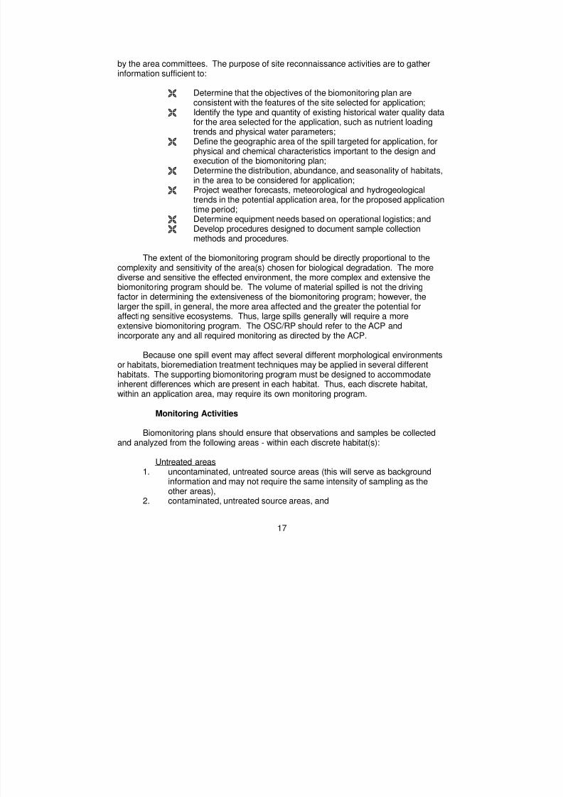
8/3/2019 Guia de selección de tecnologias aplicadas a derrames Vol II
http://slidepdf.com/reader/full/guia-de-seleccion-de-tecnologias-aplicadas-a-derrames-vol-ii 165/298
17
by the area committees. The purpose of site reconnaissance activities are to gatherinformation sufficient to:
Ë Determine that the objectives of the biomonitoring plan areconsistent with the features of the site selected for application;
Ë Identify the type and quantity of existing historical water quality datafor the area selected for the application, such as nutrient loadingtrends and physical water parameters;
Ë Define the geographic area of the spill targeted for application, forphysical and chemical characteristics important to the design andexecution of the biomonitoring plan;
Ë Determine the distribution, abundance, and seasonality of habitats,in the area to be considered for application;
Ë Project weather forecasts, meteorological and hydrogeologicaltrends in the potential application area, for the proposed applicationtime period;
Ë Determine equipment needs based on operational logistics; andË Develop procedures designed to document sample collection
methods and procedures.
The extent of the biomonitoring program should be directly proportional to thecomplexity and sensitivity of the area(s) chosen for biological degradation. The morediverse and sensitive the effected environment, the more complex and extensive thebiomonitoring program should be. The volume of material spilled is not the drivingfactor in determining the extensiveness of the biomonitoring program; however, thelarger the spill, in general, the more area affected and the greater the potential foraffecting sensitive ecosystems. Thus, large spills generally will require a moreextensive biomonitoring program. The OSC/RP should refer to the ACP andincorporate any and all required monitoring as directed by the ACP.
Because one spill event may affect several different morphological environmentsor habitats, bioremediation treatment techniques may be applied in several differenthabitats. The supporting biomonitoring program must be designed to accommodateinherent differences which are present in each habitat. Thus, each discrete habitat,within an application area, may require its own monitoring program.
Monitoring Activities
Biomonitoring plans should ensure that observations and samples be collectedand analyzed from the following areas - within each discrete habitat(s):
Untreated areas1. uncontaminated, untreated source areas (this will serve as background
information and may not require the same intensity of sampling as theother areas),
2. contaminated, untreated source areas, and

8/3/2019 Guia de selección de tecnologias aplicadas a derrames Vol II
http://slidepdf.com/reader/full/guia-de-seleccion-de-tecnologias-aplicadas-a-derrames-vol-ii 166/298
18
Treated area3. contaminated, treated areas
In order to evaluate the effectiveness of the bioremediation treatment techniquethe biomonitoring plan should provide for the comparison of replicate data from treatedand untreated areas for the duration of a project.
Within each discrete habitat which is a part of the bio application project, treatedand untreated sites that exhibit similar chemical and physical characteristics should bechosen. Their similarity will support the comparability of the data generated. Duringtheir selection the following criteria should be considered, (1) environmentalparameters, (2) physical habitat and geomorphology, and (3) oil loading and theprobability of further oiling. Site variability should be limited as much as possible inorder to generate data which is comparable.
Other physical variances which may effect the integrity of the data collected arewave action, tidal flushing, currents, boat traffic, and exposure to wind or other externalforces.
Because efficacy analyses focus on evaluating relative changes in theconcentration of the constituents of oil between treated and untreated sites, it isimportant to ensure that uncontaminated source areas remain uncontaminated for theduration of the monitoring program and contaminated areas are not reoiled for theduration of the monitoring program.
Monitoring should take in place in two forms:
1. Qualitative - serves as real time feedback for response decision and isusually in the form of visual observations, supported by photodocumentation.
2. Quantitative - serves as the basis for longer term analysis of the successof the project and is in the form of sample collection and analysis.
Although visual observation is considered subjective, there is no substitute forthis type of "real time" or fast feedback. Observers must be assigned to the project andtrained to monitor morphological changes which may occur to the oil as it breaks down
and any changes in organism behavior, such as the occurrence of algae blooms andfish kills.
All sample collection and analysis begins with a sampling plan. The samplingplans should include, at a minimum, the following:
Ë Implementation schedule (monitoring should be expected to takeplace over 3-4 months or until end points are reached)

8/3/2019 Guia de selección de tecnologias aplicadas a derrames Vol II
http://slidepdf.com/reader/full/guia-de-seleccion-de-tecnologias-aplicadas-a-derrames-vol-ii 167/298
19
Ë List of objectivesË Tasks to be conductedË Description of project managementË Identification of sensitive areas included in/adjacent to the sample
location areasË Identification of sample locations, frequency, and collection
methodsË Description of sample chain of custody procedures and QA/QC
proceduresË Description of water quality history (if available) of the affected area
or procedure for determining background values for the affectedarea if historical data does not exist
The environmental characteristics and measurements that should be assessedand the samples that should be taken as part of the biomonitoring are presented inTable 2, along with a schedule for performing these activities. Sampling at each site,water depth (as appropriate), and time, should be performed in duplicate for 10% of the samples collected . Although the mix of samples collected should be based on therequirements of the analytical methods, minimum sample sizes are recommended as 1liter for water samples and 4 - 16 oz for sediment or shoreline materials. All samplesshould be placed in precleaned jars or bottles with Teflon lined caps, as appropriate.
The monitoring parameters should involve a tiered approach which utilizesrelatively inexpensive techniques such as total petroleum hydrocarbons (TPH) forscreening and more sophisticated methods that target individual petroleum constituentsto confirm biodegradation efficacy in at least 25% of the sample s analyzed . The latterwould include GC/MS analysis of target aliphatic and aromatic hydrocarbons whichhave been identified as marker compounds for tracking oil degradation and weathering,such as the normal alkanes, the isoprenoids, pristane and phytane, and theconservative biomarker hopane. Water quality measurements should include nutrients,dissolved oxygen, biological oxygen demand (BOD), TOC and COD. Refer to AppendixE for methodologies and recommended procedures.
All data is subject to review by the OSC or a delegate and will be made availableupon request. This data will support further response decisions and to provide theresponse community with a better understanding about the use of bioremediation as anoil spill response tool.
DOCUMENTATION AND REPORTING
During the course of a bioremediation activity and accompanying monitoringeffort, the following reports shall be prepared and submitted to the OSC:
Activity reports -- provide descriptions of the bioremediation activity area,weather, unique observations, and activities undertaken, as well as the namesand affiliations of persons on site. Activity reports should be prepared

8/3/2019 Guia de selección de tecnologias aplicadas a derrames Vol II
http://slidepdf.com/reader/full/guia-de-seleccion-de-tecnologias-aplicadas-a-derrames-vol-ii 168/298
20
whenever activities on a site are undertaken.
Analytical reports -- provide laboratory analysis results of environmental andcontrol samples. Lab results should be analyzed, interpreted and a briefsummary report prepared within a reasonable time agreed to by all parties.
After action report -- provide a description of the overall bioremediation activityand accompanying monitoring effort, including results of both field andlaboratory activities. A draft should be submitted within 30 days after the endof the monitoring effort. A final report, (incorporating comments from those thedraft was submitted to, as well as photos) should be submitted within 60 daysafter submission of the draft.
In addition, at the time the final after action report is submitted, all field notes,including those of contractors, should be submitted to the OSC.
To facilitate information transfer and the development of a data base onbioremediation use and bioremediation agents, the Bioremediation Use Follow-Up Formin Appendix F should be completed at the end of the bioremediation activity.
PLAN REVISION
The monitoring plan and suggested procedures outlined in this section should beimplemented and modified, as necessary, based on the cumulative experience andknowledge gained from conducting bioremediation field activities and associatedlaboratory activities. Recommendations for revisions should be submitted to the Region4 RRT for approval.
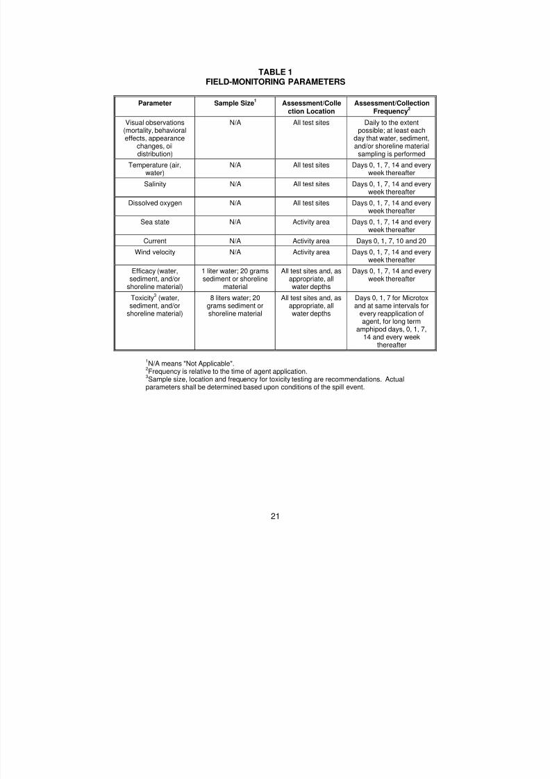
8/3/2019 Guia de selección de tecnologias aplicadas a derrames Vol II
http://slidepdf.com/reader/full/guia-de-seleccion-de-tecnologias-aplicadas-a-derrames-vol-ii 169/298
21
TABLE 1FIELD-MONITORING PARAMETERS
Parameter Sample Size1
Assessment/Collection Location
Assessment/CollectionFrequency
2
Visual observations(mortality, behavioraleffects, appearance
changes, oildistribution)
N/A All test sites Daily to the extentpossible; at least each
day that water, sediment,and/or shoreline materialsampling is performed
Temperature (air,water)
N/A All test sites Days 0, 1, 7, 14 and everyweek thereafter
Salinity N/A All test sites Days 0, 1, 7, 14 and everyweek thereafter
Dissolved oxygen N/A All test sites Days 0, 1, 7, 14 and every
week thereafter
Sea state N/A Activity area Days 0, 1, 7, 14 and everyweek thereafter
Current N/A Activity area Days 0, 1, 7, 10 and 20
Wind velocity N/A Activity area Days 0, 1, 7, 14 and everyweek thereafter
Efficacy (water,sediment, and/or
shoreline material)
1 liter water; 20 gramssediment or shoreline
material
All test sites and, asappropriate, allwater depths
Days 0, 1, 7, 14 and everyweek thereafter
Toxicity3
(water,sediment, and/or
shoreline material)
8 liters water; 20grams sediment or
shoreline material
All test sites and, asappropriate, all
water depths
Days 0, 1, 7 for Microtoxand at same intervals for
every reapplication ofagent, for long term
amphipod days, 0, 1, 7,14 and every week
thereafter
1N/A means "Not Applicable".
2Frequency is relative to the time of agent application.
3Sample size, location and frequency for toxicity testing are recommendations. Actual
parameters shall be determined based upon conditions of the spill event.

8/3/2019 Guia de selección de tecnologias aplicadas a derrames Vol II
http://slidepdf.com/reader/full/guia-de-seleccion-de-tecnologias-aplicadas-a-derrames-vol-ii 170/298
22
APPENDIX A
APPLICABLE FEDERAL AND STATE REGULATIONS
Legislation at both the federal and state level may affect decisions to usebioremediation. Existing regulations and policies that govern the use of bioremediationtreatment techniques and agents in responses to spills in Region 4 are summarizedbelow.
Federal Regulations
At the Federal level, Subpart J of the NCP governs the use of chemical andbiological agents—which include bioremediation agents—in responding to oil spills.Specifically, the Subpart:
Restricts the use of chemical and biological agents that may affect US watersto those listed on the NCP Product Schedule;
Specifies technical product information that must be submitted to EPA for anagent to be added to the Schedule; and
Establishes conditions for obtaining authorization to use chemical or biologicalagents in a response action.
If EPA determines that the required data were submitted, EPA will add the agentto the Schedule. Note, however, that listing of an agent on the NCP Product Scheduledoes not constitute approval of that agent for use or confirmation of any claimsregarding the agent's safety or effectiveness.
Data on agents listed on the NCP Product Schedule are available through EPA'sEmergency Response Division in Washington, DC.
The OSC, with concurrence of RRT 4, including the RRT representative from theState with jurisdiction over the waters threatened by the spill, may authorize the use ofany agent listed on the Product Schedule. In addition, when practicable, the OSCshould consult with the Department of Commerce (DOC) and Department of Interior(DOI) representatives to the RRT before making a decision to bioremediate a spill. Ifthe use of particular products under certain specified circumstances is approved inadvance by the State, DOC, and DOI representatives to the RRT, and suchpreapproval is specified in the Regional Contingency Plan, the OSC may authorizebioremediation without consulting the RRT.

8/3/2019 Guia de selección de tecnologias aplicadas a derrames Vol II
http://slidepdf.com/reader/full/guia-de-seleccion-de-tecnologias-aplicadas-a-derrames-vol-ii 171/298
23
State Regulations and Policies
The following States do not currently have set policies regarding the use of
bioremediation during a spill event. For approval or information, contact the State=srepresentative to the Region 4 RRT.
Alabama GeorgiaKentucky MississippiSouth Carolina Tennessee
Regulations and Policies in the State of Florida
The State of Florida does not have any regulations that specifically address the
use of bioremediation as a spill response tool. However, regulations do specify that anyperson discharging a pollutant shall immediately undertake actions to contain, remove,and abate the discharge (Chapter 376.305(l), Florida Statutes) to the satisfaction of theDepartment of Environmental Protection (DEP). The DEP does not encouragebioremediation as a primary response countermeasure, but instead it may be used inconjunction with other conventional remedial actions. The exception to this is when theoption of doing nothing is considered or conventional cleanup/treatment methods arenot feasible. In those cases, in-situ bioremediation can be an effective substitute fortraditional cleanup technologies.
The DEP has developed a set of guidelines to assist the state OSC or first
responder with bioremediation decisions and proper use. The AGuidelines for the Useof Bioremediation as a Cleanup Technique@ apply to spills of less than 50 gallons ofpetroleum on inland areas or in non-navigable waters of the state. The DEP has notestablished any guidelines or policies regarding the use of bioremediation for coastalspill response. In these cases, the DEP will work closely with the Florida MarineResearch Institute, the federal OSC and the RRT to identify areas wherebioremediation would be considered.
The use of bioremediation is prohibited for petroleum contaminated site (inlandUST sites) remedial actions unless specifically approved by the DEP Bureau of WasteCleanup, Technical Support Section. The DEP has established petroleum
contaminated soil cleanup criteria (Chapter 62-770, Florida Administrative Code) andpublishes AGuidelines for the Assessment and Remediation of PetroleumContaminated Soil@ to clarify the DEP=s position concerning petroleum contaminatedsoil remedial actions.

8/3/2019 Guia de selección de tecnologias aplicadas a derrames Vol II
http://slidepdf.com/reader/full/guia-de-seleccion-de-tecnologias-aplicadas-a-derrames-vol-ii 172/298
24
Regulations and Policies in the State of North Carolina
The State of North Carolina’s Department of Environment, Health, and NaturalResources regulates the use of bioremediation for response to spills. When requesting anevaluation to utilize bioremediation the following information must be submitted to:
Dr. Luanne WilliamsNorth Carolina Department of Environmental, Health and Natural ResourcesOccupational and Environmental Epidemiology SectionPO Box 29601Raleigh, NC 27626-0601(919) 715-6429
Required General Information
1. Division of Environmental Management (DEM) contact person and phonenumber.
2. Current or future use of site with site contact person, address & phone
number.3. Contractor applying product, contact person, address & phone number.4. Distance and impact to public or private wells used for drinking, industrial
processes, cooling, agriculture, etc. and is area served by public watersupply? Verification must be provided by the regional Groundwater andPublic Water Supply Sections. Send responses to Dr. Luanne Williams.
5. Detailed specifications of the contamination present in the soil and/orgroundwater.
6. Approximate distance & name of nearest surface water body (providemap).
Required Product/Process-Specific Information (All information submitted willbe maintained as proprietary and not disclosed to other parties.)
1. Product manufacturer name, address, phone number and contact person.2. Genus/species/strain of microorganism(s) contained in product3 Identity of specific ingredients and concentrations of ingredients contained
in the product and purpose of each.4. Documentation of evidence from authoritative technical references (i.e.
Bergey=s Manual of Systematic Bacteriology, Bergey=s Manual ofDeterminative Bacteriology or other existing references) that themicroorganism(s) are not pathogenic to animals or humans.
5. Documentation (i.e. references) of whether or not the microorganism(s)are naturally-occurring in the immediate or similar environment.
6. Documentation (i.e. references) of specific degradation productsexpected.
7. Documentation (if available) of migratory potential of microorganisms anddegradation products in soil and groundwater.
8. Complete description of the bioremediation process on a site (e.g.application of the product to soil and/or groundwater, aeration of soil,procedures needed to maintain growth and chemical degradation).

8/3/2019 Guia de selección de tecnologias aplicadas a derrames Vol II
http://slidepdf.com/reader/full/guia-de-seleccion-de-tecnologias-aplicadas-a-derrames-vol-ii 173/298
25
The risk evaluation will be forwarded to the designated contact person within thecompany, site owner, manufacturer, consultant applying the product, DEM contactperson and Groundwater Section contacts--Linda Blalock (Federal Trust Fund) andBrian Wagner (Operations Branch).

8/3/2019 Guia de selección de tecnologias aplicadas a derrames Vol II
http://slidepdf.com/reader/full/guia-de-seleccion-de-tecnologias-aplicadas-a-derrames-vol-ii 174/298
26
APPENDIX B
BIOREMEDIATION USE AUTHORIZATION FORM
The following questions should be answered, if known, and presented to theOSC who will review them and present them to the RRT for consideration. A questionleft unanswered will not automatically result in a no-go decision, but EVERY effortshould be made to present accurate and timely information. The RRT will use theinformation provided below to assist in making the decision for use of bioremediation.
The form consists of two parts, incident characteristics and feasibilityassessment criteria. Additionally, a Bioremediation Work plan and Biomonitoring Planmust be prepared and submitted to the OSC or his designee for review. (Note: Many ofthe items requested in the feasibility assessment criteria section can and should beincluded in the bioremediation Work plan.)
Incident Characteristics
Time and date of release:
Product spilled:
Quantity spilled:
Status of spill:
Location of incident:
Description of incident:
Properties of spilled product:specific or API gravityviscosity, cppour point, at temp, Fsulfur content, %w
Responsible party information:
companyaddresstelephonecontact persontelephone

8/3/2019 Guia de selección de tecnologias aplicadas a derrames Vol II
http://slidepdf.com/reader/full/guia-de-seleccion-de-tecnologias-aplicadas-a-derrames-vol-ii 175/298
27
Feasibility Assessment Criteria Specific location proposed for treatment:
What are the characteristics of the spill environment?C
type of environment, habitatC marine, brackish, freshwaterC past spill history
Amount of weathering spilled product has undergone:
Description of impact(s):
Has ownership of land been determined:
Has written permission from landowner been obtained:
Bioremediation agent proposed for use:
C Name of product.
C Typ e of agent (microbial, nutrient, microbial + nutrient, etc.).
C Isagent listed on NCP?C Has EPA data been reviewed by the SSC?C To what tier has the agent been formally evaluated?C Does the agent or responsible party have any previous first hand
experience with the use of the proposed bioremediation agent, or haveany corroborated (laboratory or field) data indicating it enhancesbiodegradation and is not toxic to affected spill environment?
C Has this agent been used on previous oil spills?C What were the characteristics of the oil and the spill environment in eachcase?
C Are degradation results (based on oil chemistry and microbial tests)available for review?
C Is a reference available?
Supply:C source of supplyC amount availableC ETA to site

8/3/2019 Guia de selección de tecnologias aplicadas a derrames Vol II
http://slidepdf.com/reader/full/guia-de-seleccion-de-tecnologias-aplicadas-a-derrames-vol-ii 176/298
28
Application:C estimated amount of agent(s) neededC who will apply the agent (vendor personnel, response contractor
personnel, or other contractor)C method to be used in applying agentC impacts of proposed application methodC time to prepare agent for applicationC has application equipment been calibrated for this particular applicationC planned rate of applicationC how long will application takeC will product have to be reapplied
- how frequently
Bioremediation Work plan
Has a bioremediation Work plan been prepared?Has the plan been reviewed?
Biomonitoring Plan
Has a biomonitoring plan been prepared?Has it been reviewed?
Project Management
Bioremediation application project manger:contact number:address:
This bioremediation application has been approved:
Federal On-Scene State On-Scene Environmental ProtectionCoordinator Coordinator Agency
Department of Department ofCommerce Interior

8/3/2019 Guia de selección de tecnologias aplicadas a derrames Vol II
http://slidepdf.com/reader/full/guia-de-seleccion-de-tecnologias-aplicadas-a-derrames-vol-ii 177/298
29
APPENDIX C
EVALUATING BIODEGRADATION POTENTIAL OF VARIOUS OILS

8/3/2019 Guia de selección de tecnologias aplicadas a derrames Vol II
http://slidepdf.com/reader/full/guia-de-seleccion-de-tecnologias-aplicadas-a-derrames-vol-ii 178/298
30
APPENDIX D
BIOREMEDIATION AGENTS AND AGENT SELECTION
This section describes the various types of bioremediation agents, a procedurefor evaluating them, and guidelines for selecting the appropriate agent for use in aparticular spill situation.
Background
Section 311 of the Clean Water Act requires that the US EnvironmentalProtection Agency (EPA) prepare a schedule of dispersants and other chemicals thatmay be used in preparing for and responding to discharges of oil and releases ofhazardous substances, as provided for in the National Oil and Hazardous Substances
Pollution Contingency Plan (NCP), 40 CFR Part 300. This schedule is known as theNCP Product Schedule. The Schedule lists agents that may be authorized for use onoil discharges in accordance with the procedures set forth in Section 300.910 of theNCP. (Authorization of use requires that the Federal On-Scene Coordinator (OSC)considering the use of a dispersant or other agent, such as a biodegradation enhancingagent, seek the concurrence of the Regional Response Team prior to the agent'sapplication.) Any agent considered for application to an oil spill should be listed on theNCP Product Schedule.
The NCP Product Schedule currently divides chemical and biological agents intofive categories:
1. dispersants,2. surface collecting agents,3. biological additives,4. burning agents, and5. miscellaneous oil spill control agents.
Most bioremediation agents, including those that are solely nutrients, are listedas biological additives, as the designed purpose of these agents is to enhance the rateof oil biodegradation by increasing microbial activity. There are also bioremediationagents listed as dispersants; these agents are water-based products that claim toenhance the rate of oil biodegradation by emulsifying spilled oil thereby making it more"bio-available." Additionally, other products that do not fit a current regulatory definitionbecause of their unique nature may be listed as miscellaneous agents. Use of any ofthese agents should be consistent with the Regional Response Team's generalguidelines for their application and use.

8/3/2019 Guia de selección de tecnologias aplicadas a derrames Vol II
http://slidepdf.com/reader/full/guia-de-seleccion-de-tecnologias-aplicadas-a-derrames-vol-ii 179/298
31
Types of Agents Types of Agents
The number and type of agents which claim to enhance the rate ofbiodegradation has broadened to fill the current perceived market. Although there are
no current regulatory definitions for every type of bioremediation agent, the followingare broad definitions for those currently available:
Microbial Agents- concentrated cultures of oil-degrading microorganisms grownon a hydrocarbon-containing medium that have been air- or freeze-dried onto a carrier(e.g., bran, cornstarch, oatmeal). In some cases, the microorganisms may be grown-upin bioreactors at the spill site. All commercially available agents use naturally-occurringmicroorganisms. Some agents may also contain nutrients to assure the activity of theirmicrobial cultures. This type of agent is intended to provide a massive inoculum of oildegrading microbes to the affected area thereby increasing the oil-degrading populationto a level where the spilled oil will be used as a primary source of food for energy.Microbial agents are designed to enhance the biodegradation of oil at any, location andwould be most useful in areas where the population of indigenous oil degraders issmall.
Nutrients -- agents containing nitrogen and/or phosphorous as the primarymeans to enhance the rate of growth of indigenous oil-degrading microorganisms. Thistype of agent is intended to increase the oil-degrading biomass already present in anaffected area to a level where the oil will be used as a primary source of food or energy.Because the natural environment may not have sufficient nutrients to encourage
bacterial metabolism and growth, extra nutrients may be required. The purpose of thistype of agent, therefore, is to provide the nutrients necessary to maintain or increasemicrobial activity and the natural biodegradation rate of spilled oil. This type of producthas been used in Prince William Sound, Alaska and Pall's Island, New Jersey to reducethe amount of oil on contaminated beaches. [For information on uses in Alaska, refer toPritchard and Costa's article entitled 'EPA's Alaska Oil Spill Bioremediation Project' inEnvironmental Science & Technology (Vol. 25(3), 1991), and the article by Chianelli et al., entitled "Bioremediation Technology Development and Application to the AlaskanSpill" in Proceedings: 1991 Oil Spill Conference.]
Enzymatic - bio-catalysts designed to enhance the emulsification and/ordispersion of oil and make it more available to microorganisms as a source of food orenergy. These agents are generally liquid concentrates, which may be mixed withsurfactants and nutrients, that are manufactured through fermentation. This type ofagent is intended to enhance biodegradation by indigenous microorganisms.
Other Agents -- include agents that do not fall under the above definitions, suchas application mechanism agents that are designed to have an affinity for oil and bringtogether the elements needed for enhanced oil degradation. Examples of applicationmechanism agents include time release capsules, liposomes, timed-release fertilizers(e.g., Custom blend), and agents that make oil more hydrophilic.

8/3/2019 Guia de selección de tecnologias aplicadas a derrames Vol II
http://slidepdf.com/reader/full/guia-de-seleccion-de-tecnologias-aplicadas-a-derrames-vol-ii 180/298
32
Agent Evaluation Procedure
In considering bioremediation agents listed on the NCP Product Schedule orproposed by agent vendors for potential use in spill cleanup, it is important that
response decision-makers evaluate the various characteristics of agents, particularlytheir safety and efficacy. From the perspective of planning for bioremediation use, themost appropriate time to evaluate agents whether performed by EPA, product vendors,or contractors - is before a spill occurs. Provided below is a procedure designedspecifically to aid in such an evaluation, which is directed ultimately at identifyingbioremediation agents that will be safe and effective in field applications. There may becircumstances, however, under which there is not adequate time to perform thoroughagent evaluations before a decision regarding bioremediation use must be made. Inthese instances, the procedure below should be used as a guide to determine whetherexisting information on individual agents is adequate to support further consideration oftheir use.
The procedure follows a "tiered" approach (a "Base Tier and four subsequenttiers) whereby bioremediation agent performance data is gathered as a means topredict the safety and efficacy of agent applications in various field settings or habitatswhere oil spills may occur. The proposed procedure is intended as a standardmethodology for assessing the effectiveness and safety of different bioremediationagents. Following the procedure will not assure that a tested agent will be effective inspill cleanup, however, following the procedure should increase the level of confidencethat use of an oil spill bioremediation agent will be effective and safe.
Base Tier -- "Go"/"No Go". Requirements and Information
Information on a bioremediation agent should be collected from the agent vendorand an initial screening of the information performed. Objectives of this screening areto:
C Ensure that the agent is listed on EPA's NCP Product Schedule.C Obtain basic information on a bioremediation agent's makeup;C Ensure satisfaction of minimal regulatory approvals that may be required;C Certify whether the agent contains pathogenic, carcinogenic, or hazardous
substances or microorganisms normally considered unacceptable forrelease into the environment; and,
Information needed from the agent vendor to perform this initial screeningincludes the agent's exact chemical and biological makeup as well as formulationcharacteristics, and proof of the agent's listing on the NCP Product Schedule.

8/3/2019 Guia de selección de tecnologias aplicadas a derrames Vol II
http://slidepdf.com/reader/full/guia-de-seleccion-de-tecnologias-aplicadas-a-derrames-vol-ii 181/298
33
Tier I -- Feasibility Assessment
Additional vendor information on a bioremediation agent should be collected tosupport an assessment of whether use of the agent is feasible. The objectives of this
tier and assessment are to obtain an understanding of a vendor's capabilities; anagent's availability, contents, and proposed method of use; and an agent's history ofuse, where applicable. Agent information needed from the vendor to perform thisassessment includes the following:
C Application rates and methods;C Mode of biodegradation and calculated efficiency;C History of use at previous cleanups;C Chemical properties, fate and persistence, and potential toxicity or
bioaccumulation for humans, mammals, and birds based on a review ofpublished literature and chemical databases;
C Acute or chronic toxicity to one marine or freshwater fish and invertebratespecies selected from US EPA's "Effluent Monitoring Program"; and,where available,
C Effectiveness in enhancing biodegradation over a baseline standard orcontrol demonstrated by descriptions and quantitative analytical results ofany laboratory or field studies performed (such as results of gaschromatographic analyses of treated and untreated samples for alkanesand/or aromatics).
A description of the management structure and qualifications of the vendor'sorganization is also needed.
Tier II - Laboratory-Scale Data
Standard laboratory methods should be used to develop data on an agent'stoxicity and its ability to stimulate the biodegradation of a standard oil. The specificobjectives of this tier are to evaluate the relative ability of a bioremediation agent todegrade oil, or stimulate the rate of biodegradation, under defined and controlledlaboratory conditions and to determine the potential toxicity associated with the agent'suse through the performance of standard toxicity tests. Analytical methods developedby EPA should be used to perform these laboratory studies.
The approach to evaluate an agent's relative effectiveness at degrading oilshould:
C Provide sufficient information to indicate with a firm degree of confidencethat the agent is degrading oil constituents;
C Provide an indicator of total microbial activity; andC Assure the viability of the culture being tested, where applicable.
The approach should include temperature, salinity, and nutrient testing todocument the conditions under which an agent's ability to degrade a standard type of oilwas determined.

8/3/2019 Guia de selección de tecnologias aplicadas a derrames Vol II
http://slidepdf.com/reader/full/guia-de-seleccion-de-tecnologias-aplicadas-a-derrames-vol-ii 182/298
34
The approach to evaluate an agent's toxicity should be conducted for specificfresh-water or marine species on the agent alone and the agent and standardized oilcombined. Seven-day chronic estimator methods should be performed using daphnia(Ceriodaphnia) and fathead minnows (Pimephales) for fresh water, and mysids(Mysidopsis) and silversides (Menidia) for marine applications. These are standardtests; additional tests specific for Regional species may be desirable. Mammaliantoxicity of agent constituents should be reviewed in existing data to determine whetherany precautions need be taken with regard to application methods, rates, or timing toprotect persons applying agents as well as indigenous wild life.
Tier Ill - Simulated Field Test Demonstration
Based on findings of previous tiers, microcosm systems should be used toperform simulated field test demonstrations on a bioremediation agent, as appropriate.The objective of this tier is to predict a bioremediation agent's effectiveness atdegrading oil or petroleum products in specific field settings or habitats.
Although EPA-approved microcosm systems for performing simulated field testdemonstrations are still under development at the time of this writing, the approach forperforming these tests is to use microcosm systems that simulate actual biodegradationfield kinetics. This approach will aid in determining the relative effectiveness andtoxicity of an agent under conditions that cannot be modeled in standard laboratorymethods, such as those proposed in Tier 11 of the procedure. Microcosm systems thatshould be considered for simulated field test demonstrations of agents include:
1. cobble beaches, both marine and fresh water;2. open water, both marine and fresh, warm and arctic;3. marshes and wetlands, both marine and fresh water;4. inland shoreline;5. sandy beaches, both marine and fresh water; and,6. land/soil.
Tier IV -- Limited Field-Scale Demonstration of the Agent
Depending on the results of the simulated field test demonstration in Tier III, alimited field scale demonstration of a bioremediation agent should be conducted. Theobjectives of this field demonstration are to test the effectiveness and toxicity of thebioremediation agent in actual field tests and to verify the accuracy of Tier Ill laboratoryresults in predicting field efficacy using the actual field monitoring data obtained. Theapproach for performing these demonstrations is to collect information during activefield testing to support an evaluation to confirm the bioremediation agent's estimatedenvironmental safety and efficacy.
At this time, EPA-approved protocols for performing limited field-scaledemonstrations in various settings are still under development. Until such protocolsbecome available, the guidelines provided in Section 6 for monitoring field applications

8/3/2019 Guia de selección de tecnologias aplicadas a derrames Vol II
http://slidepdf.com/reader/full/guia-de-seleccion-de-tecnologias-aplicadas-a-derrames-vol-ii 183/298
35
of bioremediation agents could be used for evaluating limited field-scale demonstrationsof agents.
Agent Selection
Due to a lack of specific bioremediation agent research and agent testingstandards, the selection of a bioremediation agent that will enhance the rate of oilbiodegradation must be based on best professional judgment. For most of thebioremediation agents currently on the NCP Product Schedule, there are only limitedcomparative data by which to measure their relative efficacy and safety. Some of theagents have been tested by EPA according to the procedure described above;however, these agents are not necessarily better than ones that have not been testedby these methods. Therefore, agent selection will remain largely a subjective processuntil a larger and more complete database of standard test data on agents can beassembled.
To the extent possible, the selection of bioremediation agents for potential use inoil spill cleanup against specific oils or petroleum products should take place inanticipation of an oil discharge, when time is not a critical factor. For areas where thepotential for an accidental spill is high or where there has been a high frequency ofspills (assuming the use of bioremediation agents is allowed in these areas), specificplans should be developed that outline the most likely petroleum products to be spilledand the alternative bioremediation agents that could be used to perform cleanup ofthose products in these areas.
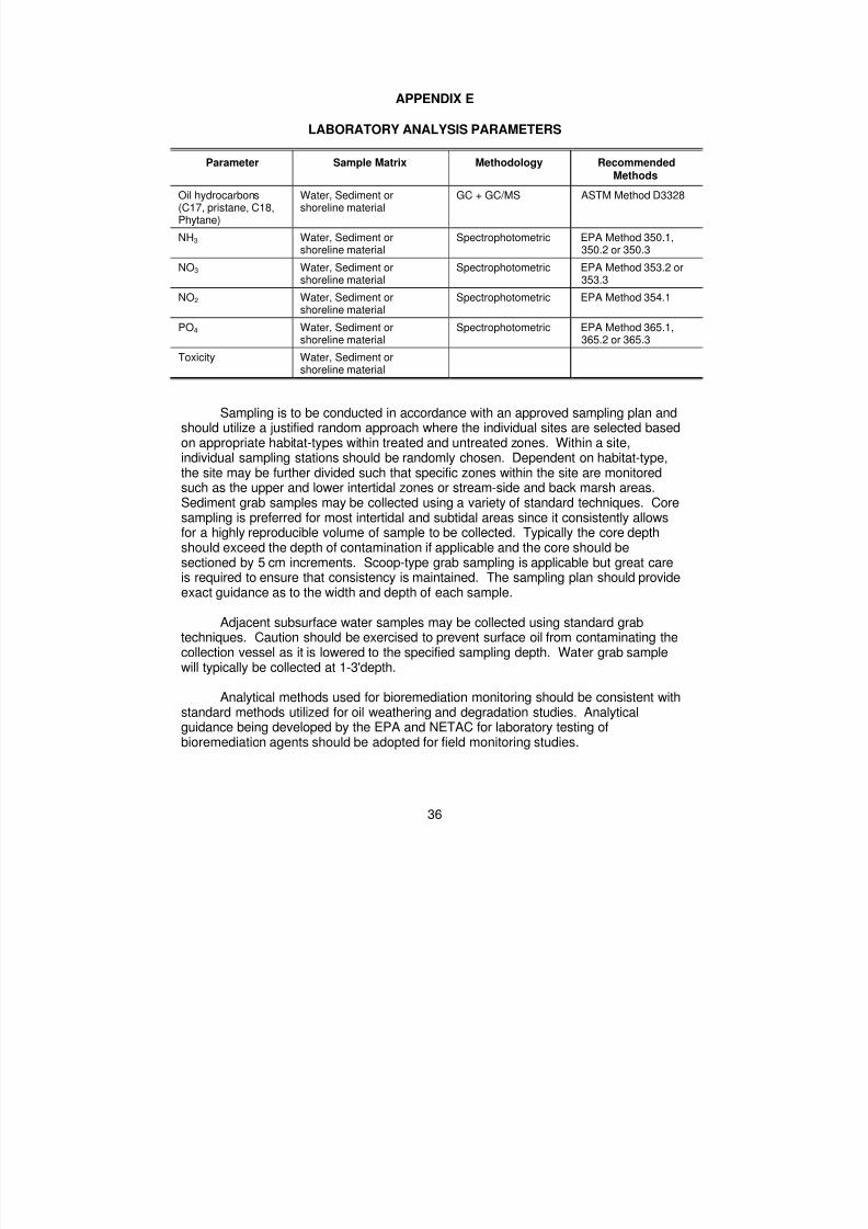
8/3/2019 Guia de selección de tecnologias aplicadas a derrames Vol II
http://slidepdf.com/reader/full/guia-de-seleccion-de-tecnologias-aplicadas-a-derrames-vol-ii 184/298
36
APPENDIX E
LABORATORY ANALYSIS PARAMETERS
Parameter Sample Matrix Methodology RecommendedMethods
Oil hydrocarbons(C17, pristane, C18,Phytane)
Water, Sediment orshoreline material
GC + GC/MS ASTM Method D3328
NH3 Water, Sediment orshoreline material
Spectrophotometric EPA Method 350.1,350.2 or 350.3
NO3 Water, Sediment orshoreline material
Spectrophotometric EPA Method 353.2 or353.3
NO2 Water, Sediment orshoreline material
Spectrophotometric EPA Method 354.1
PO4 Water, Sediment orshoreline material Spectrophotometric EPA Method 365.1,365.2 or 365.3
Toxicity Water, Sediment orshoreline material
Sampling is to be conducted in accordance with an approved sampling plan andshould utilize a justified random approach where the individual sites are selected basedon appropriate habitat-types within treated and untreated zones. Within a site,individual sampling stations should be randomly chosen. Dependent on habitat-type,the site may be further divided such that specific zones within the site are monitoredsuch as the upper and lower intertidal zones or stream-side and back marsh areas.Sediment grab samples may be collected using a variety of standard techniques. Coresampling is preferred for most intertidal and subtidal areas since it consistently allowsfor a highly reproducible volume of sample to be collected. Typically the core depthshould exceed the depth of contamination if applicable and the core should besectioned by 5 cm increments. Scoop-type grab sampling is applicable but great careis required to ensure that consistency is maintained. The sampling plan should provideexact guidance as to the width and depth of each sample.
Adjacent subsurface water samples may be collected using standard grabtechniques. Caution should be exercised to prevent surface oil from contaminating thecollection vessel as it is lowered to the specified sampling depth. Water grab samplewill typically be collected at 1-3'depth.
Analytical methods used for bioremediation monitoring should be consistent withstandard methods utilized for oil weathering and degradation studies. Analyticalguidance being developed by the EPA and NETAC for laboratory testing ofbioremediation agents should be adopted for field monitoring studies.

8/3/2019 Guia de selección de tecnologias aplicadas a derrames Vol II
http://slidepdf.com/reader/full/guia-de-seleccion-de-tecnologias-aplicadas-a-derrames-vol-ii 185/298
37
Field and laboratory blanks should be specified in the monitoring plan andshould represent at least 10% of the samples analyzed. To assess environmentalvariability, 10% of the sample stations should be sampled and analyzed in triplicate.Since no certified reference material is currently available for oil bioremediationmonitoring, a reference sample of the spilled oil should be analyzed periodically toverify laboratory consistency. Quantitative values for the reference oil should not varyby more than 20% for selected analytes. Good laboratory practices should beemployed that are consistent with the objectives of the biomonitoring plan.
Accurate sample identification and proper control of samples is essential. Achain of custody procedure will be established and implemented which will ensureintegrity of the samples and proper handling of the samples.

8/3/2019 Guia de selección de tecnologias aplicadas a derrames Vol II
http://slidepdf.com/reader/full/guia-de-seleccion-de-tecnologias-aplicadas-a-derrames-vol-ii 186/298
38
APPENDIX F
INFORMATION FEEDBACK:BIOREMEDIATION USE FOLLOW-UP FORM
Lessons learned from a spill cleanup operation are most useful when others,particularly those not personally involved in the original cleanup operation, can benefitfrom them by drawing upon the original responders' experiences. Region 4 hasestablished a program to facilitate the collection and transfer of information on uses ofbioremediation that is intended to provide decision makers with case data upon whichfuture decisions regarding bioremediation may be based. Particularly becauseresponse officials have very limited experience with bioremediation in uncontrolledenvironments, such as open water and other marine areas, this program is expected tobe a valuable resource for supporting informed decisions regarding bioremediation.
The principal objective of this bioremediation information feedback program inRegion 4 are as follows:
To gather relevant, accurate, descriptive, and complete information from sites —where bioremediation has been used for spill response; and
To provide that information via an accessible network to future decision makerswho are considering the use of bioremediation.
The Bioremediation Use Follow-Up Form on the following pages has beenprovided to guide information collection efforts in support of this program. A separateform should be completed for each unique bioremediation activity. Because certaininformation may not have been anticipated when the form was developed, feel free toprovide any other information deemed appropriate regarding the use of bioremediationin a particular response action.
BIOREMEDIATION USE FOLLOW-UP FORM
A. SPILL INFORMATION
1. Spill event2. Date3. Location (e.g., offshore, wetlands, coastal)4. Product(s) spilled5. Amount of spill6. Reason(s) for using bioremediation7. Age of oil when bioremediation agents applied

8/3/2019 Guia de selección de tecnologias aplicadas a derrames Vol II
http://slidepdf.com/reader/full/guia-de-seleccion-de-tecnologias-aplicadas-a-derrames-vol-ii 187/298
39
B. BIOREMEDIATION AGENT INFORMATION
1 . First Treatment or Application:a. Type of agent applied (e.g., nutrient, microbial, enzyme)b. Name of agentc. Agent listed on the NCP Product Schedule?d. Vendore. Vendor address and phone numberf. Rate effectiveness (compared to control site) on a scale of 1 to 10,
10 being the highest score Visual observation Oil chemistry Methodused (e.g., GC, GC/MS, TPH)
2. Second Treatment or Application (complete if different from above):a. Type of agent applied (e.g., nutrient, microbial, enzyme)b. Name of agentc. Agent listed on the NCP Product Schedule?d. Vendore. Vendor address and phone numberf. Rate effectiveness (compared to control site) on a scale of 1 to 10,
10 being the highest scoreVisual observationOil chemistryMethod used (e.g., GC, GC/MS, TPH)
3. Third Treatment or Application (complete if different from above):a. Type of agent applied (e.g., nutrient, microbial, enzyme)b. Name of agentc. Agent listed on the NCP Product Schedule?d. Vendore. Vendor address and phone numberf. Rate effectiveness (compared to control site) on a scale of 1 to 10,
10 being the highest scoreVisual observationOil chemistryMethod used (e.g., GC, GC/MS, TPH)
C. SITE CONTROLS1. Size and number of test site(s)
2. Size and number of control site(s)3. Site security measures taken

8/3/2019 Guia de selección de tecnologias aplicadas a derrames Vol II
http://slidepdf.com/reader/full/guia-de-seleccion-de-tecnologias-aplicadas-a-derrames-vol-ii 188/298
40
D. TREATMENT AREA LOCATION1 . On water (latitude and longitude)2. Shoreline (latitude and longitude)
Shoreline type (e.g., sand, shell, cobble)Shoreline zone (e.g., intertidal, surge, storm/overwash)Depth of shoreline oiling
E. APPLICATION INFORMATION1. Microbial counts before application2. Microbial counts after application3. Applications performed by (names and titles)4. Application method(s) used5. Application date(s)6. Application conditions (e.g., winds, waves)7. Agent concentration and rates (e.g., gal/acre)8. Additional information on re-applications
F. MONITORING1 . Schedule and duration (e.g., weekly for 3 months)2. Method (e.g., foot, by air, boat)3. Monitoring performed by (names and titles)4. Toxicity noted
G. PROBLEMS ENCOUNTERED (e.g., weather, site security, application)
H. LESSONS LEARNED1. CONTACTS
a. OSC (name, address, and phone)b. SSC (name, address, and phone)c. Form completed by (name, title, and agency)

8/3/2019 Guia de selección de tecnologias aplicadas a derrames Vol II
http://slidepdf.com/reader/full/guia-de-seleccion-de-tecnologias-aplicadas-a-derrames-vol-ii 189/298
41
APPENDIX G
REFERENCES
Anderson, J.P.E. "Principles of and Assay Systems for Biodegradation." Biotechnology and Biodegradation, vol. 4, Advances in Applied Biotechnology Series. Texas:The Portfolio Publishing Company, 1990, pp. 129-146.
Atlas, R.M. "Biodegradation of Hydrocarbons in the Environment," Environmental Biotechnology. New York: Plenum Press, 1988.
Atlas, Ronald M. "Microbial Degradation of Petroleum Hydrocarbons: an EnvironmentalPerspective." Microbiological Reviews. March 1981, pp. 180-209.
Leahy, J.G. and R.R. Colwell. "Microbial Degradation of Hydrocarbons in theEnvironment." Microbiological Reviews. September 1990.
Ponier, Ralph J. "Bioremediation Using Adapted Bacterial Cultures, Topic 1:Examination of Site Data and Discussion of Microbial Physiology With Regard toSite Remediation." Proceedings of the Hazardous Materials Control Research Institute's First National Conference on Bioremediation. 1990, pp. 321-361.
US Environmental Protection Agency. Guide for Preparation of Quality Assurance Project Plans for the National Estuarine Program. EPA 556/2-88-001. Office ofMarine and Estuarine Protection, Washington, DC June 1988.

8/3/2019 Guia de selección de tecnologias aplicadas a derrames Vol II
http://slidepdf.com/reader/full/guia-de-seleccion-de-tecnologias-aplicadas-a-derrames-vol-ii 190/298
42
ADDITIONAL SOURCES OF INFORMATION ON BIOREMEDIATION
Ahearn, D.G. "Microbial Degradation of Oil Pollutants." Workshop, Georgia StateUniversity, December 4-6, 1972. Proceedings: Louisiana State University Center
for Wetland Resources, Publication LSU-SG-73-01, 1973.
Chianelli, R.R., et al. "Bioremediation Technology Development and Application to theAlaskan Spill." Proceedings: 1991 Oil Spill Conference. March 4-7, 1991, SanDiego, California, pp. 549-558.
Congress of the United States. Bioremediation for Marine O# Spills. OTA-BP-0-70.Office of Technology Assessment, Washington, D.C. May 1991.
DeLune, R.D., R.P. Gambrell, J.H.Pardue and W.H.Patrick, Jr. "Fate of PetroleumHydrocarbons and Toxic Organics in Louisiana Coastal Environments." Estuaries.
13(1), 1990, pp. 72-80.
Jordan, Randolph and James R. Payne. Fate and Weathering of Petroleum Spills in the Marine Environment. Michigan: Ann Arbor Science Publishers, Inc., 1980.
Lee, Richard F. "Metabolism of Petroleum Hydrocarbons in Marine Sediments."Proceedings of a Symposium on Sources, Effects and Sinks of Hydrocarbons in the Aquatic Environment. AIBS Publication, 1976.
Mearns, Alan J. Observations of an Oil Spill Bioremediation Activity in Galveston Bay,Texas. NOAA Technical Memorandum NOS OMA 57. June 1991.
Owen, D. "Bioremediation of Marine Oil Spills: Scientific and Operational Constraints,"Proceedings of the Fourteenth Arctic and Marine Oil Spill Program TechnicalSeminar. Vancouver, British Columbia, June 12-14, 1991, pp. 119-130.
Pitter, Pavel and Jan Chudoba. Biodegradability of Organic Substances in the Aquatic Environment. Boca Raton, Florida: CRC Press, 1990.
Pritchard, P. Hap and Charles F. Costa. "EPA's Alaska Oil Spill BioremediationProject." Environmental Science & Technology. 25 (3), 1991, pp. 372-382.
Sauer, Ted and Paul Boehm. "The Use of Defensible Analytical ChemicalMeasurements for Oil Spill Natural Resource Damage Assessment."Proceedings: 1991 Oil Spill Conference. pp. 363-369.
Venosa, A.D. and J.R. Haines. "Screening of Commercial Innocula for Efficacy inStimulating Oil Biodegradation in a Closed Laboratory System." Journal of Hazardous Materials. 28: 131-144, 1991.

8/3/2019 Guia de selección de tecnologias aplicadas a derrames Vol II
http://slidepdf.com/reader/full/guia-de-seleccion-de-tecnologias-aplicadas-a-derrames-vol-ii 191/298
NRT Bioremediation Fact Sheet
1 WORKING DRAFT 6/00
BIOREMEDIATION IN OIL SPILLRESPONSE
Contact: Albert D. VenosaU.S. EPA, Cincinnati, OH 45268
Tel: 513-569-7668 Fax: 513-569-7105Email: [email protected]
SUMMARY
The purpose of this fact sheet is to provide on scenecoordinators and other decision-makers with the latestinformation on evolving technologies that may beapplicable for use in responding to an oil spill.Bioremediation is one technique that may be useful toremove spilled oil under certain geographic and climaticconditions. For the purpose of this effort, bioremediation isdefined to include the use of nutrients to enhance theactivity of indigenous organisms and/or the addition of naturally-occurring non-indigenous microorganisms.
BACKGROUND
Many compounds in crude oil are environmentally benign,
but significant fractions are toxigenic or mutagenic. Thelatter are the ones we are most interested in removing or destroying in an oil spill. Bioremediation is a technologythat offers great promise in converting the toxigeniccompounds to nontoxic products without further disruptionto the local environment.
When microorganisms break down petroleumhydrocarbons, the first step usually is addition of ahydroxyl group to the end of an alkane chain or onto anunsaturated ring of a polycyclic aromatic hydrocarbon(PAH), forming an alcohol. Progressive oxidation to analdehyde and then a carboxylic acid leads to chain lengthreduction and eventually to production of carbon dioxide,water, and biomass. In the case of the PAH, ring fissiontakes place, again leading eventually to mineralization. As
oxygen is added to hydrocarbons, the compounds becomemore polar and thus more water soluble. These compoundsare usually more easily biodegradable and thus less toxic.Although the more polar compounds are more likely toenter the water column as biodegradation ensues, they areunlikely to cause environmental damage or toxic effects tonearby biota. Furthermore, the amount of dilution availablefrom the tidal waters is so great that the amounts of benign polar constituents entering the food chain are likely to benegligible. Thus, the effect of biochemical end productsfrom the easily metabolizable compounds in oil will beinsignificant in the environment.
REQUIREMENTS FOR SUCCESS
Since the contaminants of concern in crude oil are readily biodegradable under appropriate conditions, the success of oil-spill bioremediation depends on our ability to establishthose conditions in the contaminated environment. Themost important requirement is that bacteria withappropriate metabolic capabilities must be present. If theyare, their rates of growth and hydrocarbon biodegradationcan be maximized by ensuring that adequate concentrationsof nutrients and oxygen are present and that the pH is between about 6 and 91. The physical and chemicalcharacteristics of the oil are also important determinants of bioremediation success. Heavy crude oils that containlarge amounts of resin and asphaltene compounds are less
amenable to bioremediation than are light- or medium-weight crude oils that are rich in aliphatic components.Finally, the oil surface area is extremely important becausegrowth of oil degraders occurs almost exclusively at theoil-water interface1.
Obviously, some of these factors can be manipulated moreeasily than others. For example, nothing can be done aboutthe chemical composition of the oil, and no adequateengineering approaches are currently available for
providing oxygen to oil-contaminated surficial sedimentsin the intertidal zone. Therefore, the two main approachesto oil-spill bioremediation are: (1) bioaugmentation, inwhich oil-degrading bacteria are added to supplement theexisting microbial population, and (2) biostimulation, inwhich nutrients or other growth-limiting co-substrates areadded to stimulate the growth of indigenous oil degraders.Since oil-degrading bacteria usually grow at the expense of one or more components of crude oil, and these organismsare ubiquitous2-4, there is usually no reason to addhydrocarbon degraders unless the indigenous bacteria areincapable of degrading one or more importantcontaminants. The size of the hydrocarbon-degrading bacterial population usually increases rapidly in responseto oil contamination, and it is very difficult, if notimpossible, to increase the microbial population over thatwhich can be achieved by biostimulation alone5-8 Thecarrying capacity of most environments is probablydetermined by factors such as predation by protozoans, theoil surface area, or scouring of attached biomass by waveactivity that are not affected by bioaugmentation, andadded bacteria seem to compete poorly with the indigenous population9, 10 Therefore, it is unlikely that they will persistin a contaminated beach even when they are added in highnumbers. As a result, bioaugmentation has never beenshown to have any long-term beneficial effects in shorelinecleanup operations.
Biostimulation involves the addition of rate-limitingnutrients to accelerate biodegradation by indigenousmicroorganisms. When an oil spill occurs, it results in a
huge influx of carbon into the impacted environment.Carbon is the basic structural component of living matter,and in order for the indigenous microorganisms to be ableto convert this carbon into more biomass, they needsignificantly more nitrogen and phosphorus than isnormally present in the environment. Both of theseelements are essential ingredients of protein and nucleicacids of living organisms. The main challenge associatedwith biostimulation in oil-contaminated coastal areas or tidally influenced freshwater rivers and streams ismaintaining optimal nutrient concentrations in contact withthe oil.
NUTRIENT APPLICATION
Effective bioremediation requires nutrients to remain incontact with the oiled material, and the concentrationsshould be sufficient to support the maximal growth rate of the oil-degrading bacteria throughout the cleanupoperation. Because of these requirements, bioremediationof open water spills is not considered appropriate or achievable. When nutrients are added to a floating slick,they will immediately disperse into the water column,essentially diluting to levels close to background. At suchlevels, rapid conversion of the hydrocarbons to biomass,CO2, and other innocuous end products would not besupported readily.
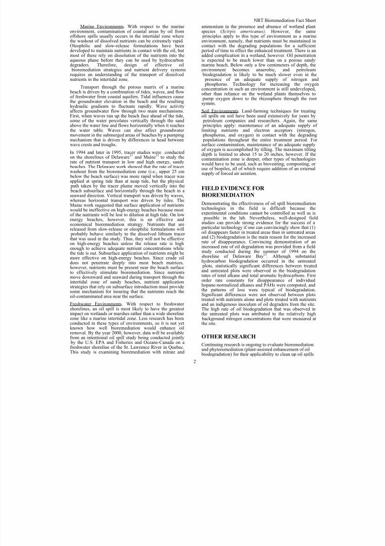
8/3/2019 Guia de selección de tecnologias aplicadas a derrames Vol II
http://slidepdf.com/reader/full/guia-de-seleccion-de-tecnologias-aplicadas-a-derrames-vol-ii 192/298
NRT Bioremediation Fact Sheet
2
Marine Environments. With respect to the marineenvironment, contamination of coastal areas by oil fromoffshore spills usually occurs in the intertidal zone wherethe washout of dissolved nutrients can be extremely rapid.Oleophilic and slow-release formulations have beendeveloped to maintain nutrients in contact with the oil, butmost of these rely on dissolution of the nutrients into theaqueous phase before they can be used by hydrocarbondegraders. Therefore, design of effective oil bioremediation strategies and nutrient delivery systems
requires an understanding of the transport of dissolvednutrients in the intertidal zone.
Transport through the porous matrix of a marine beach is driven by a combination of tides, waves, and flowof freshwater from coastal aquifers. Tidal influences causethe groundwater elevation in the beach and the resultinghydraulic gradients to fluctuate rapidly. Wave activityaffects groundwater flow through two main mechanisms.First, when waves run up the beach face ahead of the tide,some of the water percolates vertically through the sandabove the water line and flows horizontally when it reachesthe water table. Waves can also affect groundwater movement in the submerged areas of beaches by a pumpingmechanism that is driven by differences in head betweenwave crests and troughs.
In 1994 and later in 1995, tracer studies were conductedon the shorelines of Delaware11 and Maine12 to study therate of nutrient transport in low and high energy, sandy beaches. The Delaware work showed that the rate of tracer washout from the bioremediation zone (i.e., upper 25 cm below the beach surface) was more rapid when tracer wasapplied at spring tide than at neap tide, but the physical path taken by the tracer plume moved vertically into the beach subsurface and horizontally through the beach in aseaward direction. Vertical transport was driven by waves,whereas horizontal transport was driven by tides. TheMaine work suggested that surface application of nutrientswould be ineffective on high-energy beaches because mostof the nutrients will be lost to dilution at high tide. On low
energy beaches, however, this is an effective andeconomical bioremediation strategy. Nutrients that arereleased from slow-release or oleophilic formulations will probably behave similarly to the dissolved lithium tracer that was used in the study. Thus, they will not be effectiveon high-energy beaches unless the release rate is highenough to achieve adequate nutrient concentrations whilethe tide is out. Subsurface application of nutrients might bemore effective on high-energy beaches. Since crude oildoes not penetrate deeply into most beach matrices,however, nutrients must be present near the beach surfaceto effectively stimulate bioremediation. Since nutrientsmove downward and seaward during transport through theintertidal zone of sandy beaches, nutrient applicationstrategies that rely on subsurface introduction must providesome mechanism for insuring that the nutrients reach theoil-contaminated area near the surface.
Freshwater Environments. With respect to freshwater shorelines, an oil spill is most likely to have the greatestimpact on wetlands or marshes rather than a wide shorelinezone like a marine intertidal zone. Less research has beenconducted in these types of environments, so it is not yetknown how well bioremediation would enhance oilremoval. By the year 2000, however, data will be availablefrom an intentional oil spill study being conducted jointly by the U.S. EPA and Fisheries and Oceans-Canada on afreshwater shoreline of the St. Lawrence River in Quebec.This study is examining bioremediation with nitrate and
ammonium in the presence and absence of wetland plantspecies (Scirpis americanus). However, the same principles apply to this type of environment as a marineenvironment, namely, that nutrients must be maintained incontact with the degrading populations for a sufficient period of time to effect the enhanced treatment. There is anadded complication in a wetland, however. Oil penetrationis expected to be much lower than on a porous sandymarine beach. Below only a few centimeters of depth, theenvironment becomes anaerobic, and petroleum
biodegradation is likely to be much slower even in the presence of an adequate supply of nitrogen and phosphorus. Technology for increasing the oxygenconcentration in such an environment is still undeveloped,other than reliance on the wetland plants themselves to pump oxygen down to the rhizosphere through the rootsystem.
Soil Environments. Land-farming techniques for treatingoil spills on soil have been used extensively for years by petroleum companies and researchers. Again, the same principles apply: maintenance of an adequate supply of limiting nutrients and electron acceptors (nitrogen, phosphorus, and oxygen) in contact with the degrading populations throughout the entire treatment period. For surface contamination, maintenance of an adequate supplyof oxygen is accomplished by tilling. The maximum tillingdepth is limited to about 15 to 20 inches, however. If thecontamination zone is deeper, other types of technologieswould have to be used, such as bioventing, composting, or use of biopiles, all of which require addition of an externalsupply of forced air aeration.
FIELD EVIDENCE FOR
BIOREMEDIATION
Demonstrating the effectiveness of oil spill bioremediationtechnologies in the field is difficult because theexperimental conditions cannot be controlled as well as is possible in the lab. Nevertheless, well-designed fieldstudies can provide strong evidence for the success of a particular technology if one can convincingly show that (1)oil disappears faster in treated areas than in untreated areasand (2) biodegradation is the main reason for the increasedrate of disappearance. Convincing demonstration of anincreased rate of oil degradation was provided from a fieldstudy conducted during the summer of 1994 on theshoreline of Delaware Bay13. Although substantialhydrocarbon biodegradation occurred in the untreated plots, statistically significant differences between treatedand untreated plots were observed in the biodegradationrates of total alkane and total aromatic hydrocarbons. Firstorder rate constants for disappearance of individualhopane-normalized alkanes and PAHs were computed, andthe patterns of loss were typical of biodegradation.
Significant differences were not observed between plotstreated with nutrients alone and plots treated with nutrientsand an indigenous inoculum of oil degraders from the site.The high rate of oil biodegradation that was observed inthe untreated plots was attributed to the relatively high background nitrogen concentrations that were measured atthe site.
OTHER RESEARCH
Continuing research is ongoing to evaluate bioremediationand phytoremediation (plant-assisted enhancement of oil biodegradation) for their applicability to clean up oil spills

8/3/2019 Guia de selección de tecnologias aplicadas a derrames Vol II
http://slidepdf.com/reader/full/guia-de-seleccion-de-tecnologias-aplicadas-a-derrames-vol-ii 193/298
NRT Bioremediation Fact Sheet
3
contaminating salt marshes and freshwater wetlands. Datawill be available in the year 2000 for the freshwater wetland study and 2001 for the salt marsh. By December of 2000, EPA is planning to produce a draft guidancedocument detailing the use of bioremediation for sandymarine beaches and freshwater wetlands. EPA is alsostudying the biodegradability of non-petroleum oils(vegetable oils and animal fats) and their impacts on theenvironment during biodegradation. Reports will beavailable some time in 2000.
CONCLUSION
In conclusion, bioremediation is a proven alternativetreatment tool that can be used to treat certain aerobic oil-contaminated environments. Typically, it is used as a polishing step after conventional mechanical cleanupoptions have been applied. It is a relatively slow process,requiring weeks to months to effect cleanup. If done properly, it can be very cost-effective, although an in-deptheconomic analysis has not been conducted to date. It hasthe advantage that the toxic hydrocarbon compounds aredestroyed rather than simply moved to another environment. The biggest challenge facing the responder is
maintaining the proper conditions for maximal biodegradation to take place, i.e., maintaining sufficientnitrogen and phosphorus concentrations in the pore water at all times (~5-10 mg N/L). Based on solid evidence fromthe literature, it appears that addition of exogenous culturesof microorganisms will not enhance the process more thansimple nutrient addition. Bioremediation is not considereda primary response tool, although it could be so used if thespilled oil does not exist as free product and if the area isremote enough not to require immediate cleanup to satisfya tourism industry. If the affected environment is a highenergy shoreline, bioremediation will be less likelyeffective than on a lower energy shoreline. Application of dry granular fertilizer to the impact zone is probably themost cost-effective way to control nutrient concentrations.
REFERENCES
1. Altas, R.M. and R. Bartha. 1972. Degradation and
mineralization of petroleum in sea water: Limitation
by nitrogen and phosphorous. Biotech. Bioeng. 14:
309-318.
2. Mulkins-Phillips, G.J. and J.E. Stewart. 1974.
Distribution of hydrocarbon-utilizing bacteria in
northwestern Atlantic waters and coastal sediments.
Can. J. Microbiol. 20: 955-962.
3. Roubal, G. and R.M. Atlas. 1978. Distribution of
hydrocarbon-utilizing microorganisms and
hydrocarbon biodegradation potentials in Alaskan
continental shelf areas. Appl. Environ. Microbiol. 35:897-905.
4. Atlas, R.M. 1981. Microbial degradation of
petroleum hydrocarbons: an environmental
perspective. Microbiological Rev. 45: 180-209.
5. Jobson, A.M., M. McLaughlin, F.D. Cook, and
D.W.S. Westlake. 1974. Appl. Microbiol. 27:166-171.
6. Westlake, D.W.S., A.M. Jobson, and F.D. Cook.
Canad. J. Microbiol. 24:245-260.
7. Lee, K. and E.M. Levy. 1987. Proc. 1987 International
Oil Spill Conference, American Petroleum Institute,
Washington, D.C.
8. Lee, K., G.H. Tremblay, J. Gauthier, S.E. Cobanli, and
M. Griffin. 1997. Bioaugmentation and
biostimulation: A paradox between laboratory and
field results. pp. 697-705. In Proceedings, 1997
International Oil Spill Conference. American
Petroleum Institute, Washington, DC.9. Tagger, S., A. Bianchi, M. Juillard, J. LePetit, and B.
Roux. 1983. Effect of microbial seeding of crude oil
in seawater in a model system. Mar. Biol. 78: 13-20.
10. Lee, K. and E.M. Levy. 1989. Enhancement of the
natural biodegradation of condensate and crude oil on
beaches of Atlantic Canada. pp. 479-486. In
Proceedings, 1989 Oil Spill Conference. American
Petroleum Institute, Washington, DC.
11. Wrenn, B.A., M.T. Suidan, K.L. Strohmeir, B.L.
Eberhart, G.J. Wilson, and A.D. Venosa. 1997.
“Nutrient transport during bioremediation of
contaminated beaches: evaluation with lithium as a
conservative tracer.” Wat. Res. 31(3):515-524.
12. Wrenn, B.A., M. C. Boufadel, M.T. Suidan, and A.D.
Venosa. 1997. “Nutrient transport during
bioremediation of crude oil contaminated beaches.” In:
In Situ and On-Site Bioremediation: Volume 4, pp.
267-272. Battelle Memorial Institute, Columbus, OH.
13. Venosa, A.D., M.T. Suidan, B.A. Wrenn, K.L.
Strohmeier, J. R. Haines, B.L. Eberhart, D. King, and
E. Holder. 1996. “Bioremediation of an experimental
oil spill on the shoreline of Delaware Bay.”
Environmental. Sci. and Technol. 30(5):1764-1775.

8/3/2019 Guia de selección de tecnologias aplicadas a derrames Vol II
http://slidepdf.com/reader/full/guia-de-seleccion-de-tecnologias-aplicadas-a-derrames-vol-ii 194/298
4 WORKING DRAFT 6/00
6/30/00
This page intentionally left blank

8/3/2019 Guia de selección de tecnologias aplicadas a derrames Vol II
http://slidepdf.com/reader/full/guia-de-seleccion-de-tecnologias-aplicadas-a-derrames-vol-ii 195/298
1 WORKING DRAFT 6/006/30/00
OOTTHHEERR CCOOUUNNTTEERRMMEEAASSUURREESS PPLLAANNSS
Introduction This section of the Selection Guide provides the decision-maker
with a placeholder for future regional operational and
implementation plans for applied technologies.
Purpose As future use of applied technologies continues, region-specific
guidance may be developed, lessons learned captured, etc. This
information can be stored in this section for future reference.
NOTE: The Region IV Inland In situ Burn Plan has been provided
in this Selection Guide as a starting point for Region III’s use. It is
included in this Guide without revisions and is awaiting Region III
revision and comment.

8/3/2019 Guia de selección de tecnologias aplicadas a derrames Vol II
http://slidepdf.com/reader/full/guia-de-seleccion-de-tecnologias-aplicadas-a-derrames-vol-ii 196/298
2
06/30/00
This page intentionally left blank
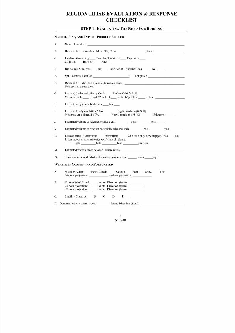
8/3/2019 Guia de selección de tecnologias aplicadas a derrames Vol II
http://slidepdf.com/reader/full/guia-de-seleccion-de-tecnologias-aplicadas-a-derrames-vol-ii 197/298
REGION III ISB EVALUATION & RESPONSE
CHECKLIST
1
6/30/00
STEP 1: EVALUATING THE NEED FOR BURNING
NATURE, SIZE, AND TYPE OF PRODUCT SPILLED
A. Name of incident: __________________________________________________________________
B. Date and time of incident: Month/Day/Year ___________________; Time _____________________
C. Incident: Grounding ____ Transfer Operations ____ Explosion ____
Collision ____ Blowout ____ Other __________________________________________________
D. Did source burn? Yes ____ No ____ Is source still burning? Yes ____ No _____
E. Spill location: Latitude _________________________; Longitude _________________________
F. Distance (in miles) and direction to nearest land: _________________________________________
Nearest human use area: _____________________________________________________________
G. Product(s) released: Heavy Crude ____ Bunker C/#6 fuel oil ____
Medium crude ____ Diesel/#2 fuel oil ____ Jet fuels/gasoline _____ Other ____________________
H. Product easily emulsified? Yes ____ No ____
I. Product already emulsified? No ____ Light emulsion (0-20%) ______
Moderate emulsion (21-50%) ______ Heavy emulsion (>51%) ______ Unknown _______
J. Estimated volume of released product: gals ________ bbls ________ tons
K. Estimated volume of product potentially released: gals ________ bbls ________ tons ________
L. Release status: Continuous ____ Intermittent ____ ; One time only, now stopped? Yes ____ No ____
If continuous or intermittent, specify rate of release:
gals __________ bbls __________ tons __________ per hour
M. Estimated water surface covered (square miles): __________________________________________
N. If ashore or onland, what is the surface area covered: ______ acres ______sq ft
WEATHER : CURRENT AND FORECASTED
A. Weather: Clear ____ Partly Cloudy ____ Overcast ____ Rain ____ Snow ____ Fog ____
24-hour projection: _____________ 48-hour projection: _____________
B. Current Wind Speed: _____ knots Direction (from): ___________
24-hour projection: _____ knots Direction (from): ___________
48-hour projection: _____ knots Direction (from): ___________
C. Stability Class: A ____ B ____ C ____ D ____ E ____
D. Dominant water current: Speed _________ knots; Direction (from): ______________________________

8/3/2019 Guia de selección de tecnologias aplicadas a derrames Vol II
http://slidepdf.com/reader/full/guia-de-seleccion-de-tecnologias-aplicadas-a-derrames-vol-ii 198/298
REGION III ISB EVALUATION & RESPONSE CHECKLIST
2
6/30/00
E. Wave Conditions: Calm ____ Choppy ____
Waves: <1 ft ____ 1-3 ft ____ >3 ft ____
24-hour projection: __________ 48-hour projection: _____________
F. Ice Present: Yes ____ No ____;
Percent coverage: <10% ____ 11-30% ____ 31-50% ____ 51-100% ____
TRAJECTORIES OF SPILL - ON-WATER BURNING
A. Estimated trajectory (see attached chart/map):
B. Expected area(s) and time(s) of land fall: ________________________________________________
________________________________________________________________________________________
________________________________________________________________________________________
(see attached chart/map)
C. Estimated percent naturally dispersed and evaporated within first 24 hours:
__________________________________________________________________________ EVALUATION OF R ESPONSE OPERATIONS
A. Considering spill size, forecasted weather and trajectories, amount of available equipment, is there time
to deploy mechanical recovery equipment? Yes ____ No ____
B. Has dispersant use been fully evaluated? Yes ____ No ____
Results: __________________________________________________________________________
________________________________________________________________________________________
C. Why is in situ burning necessary? ( provide a brief explanation)
________________________________________________________________________________________
________________________________________________________________________________________ ________________________________________________________________________________________
STEP 2: BURNING FEASIBILITY CHECKLIST
WEATHER , SEA, AND OIL CONDITIONS
A. Wind: < 20 Knots? Yes ____ No ____
B. Waves: < 3 feet in choppy wind driven seas? Yes ____ No ____
C. Currents: < 0.75 knots relative velocity boom/water? Yes ____ No ____
D. Visibility: Sufficient to see oil, containment systems, and suitable for aerial overflight for burn
observation? Yes ____ No ____
E. Oil Condition: 1. Fresh oil,< 2-3 days exposure Yes ____ No ____
2. >2-3 mm, (0.1 inch) thickness Yes ____ No ____
3. < 25% water content for optimal ignition Yes ____ No ____
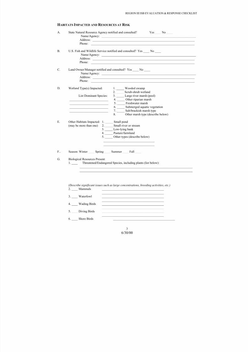
8/3/2019 Guia de selección de tecnologias aplicadas a derrames Vol II
http://slidepdf.com/reader/full/guia-de-seleccion-de-tecnologias-aplicadas-a-derrames-vol-ii 199/298
REGION III ISB EVALUATION & RESPONSE CHECKLIST
3
6/30/00
HABITATS IMPACTED AND R ESOURCES AT R ISK
A. State Natural Resource Agency notified and consulted? Yes ____ No ____
Name/Agency: _____________________________________________________________
Address: __________________________________________________________________
Phone: ___________________________________________________________________
B. U.S. Fish and Wildlife Service notified and consulted? Yes ____ No ____
Name/Agency: _____________________________________________________________
Address: __________________________________________________________________
Phone: ___________________________________________________________________
C. Land Owner/Manager notified and consulted? Yes ____ No ____
Name/Agency: _____________________________________________________________
Address: __________________________________________________________________
Phone: ___________________________________________________________________
D. Wetland Type(s) Impacted: 1. _____ Wooded swamp
2. _____ Scrub-shrub wetland
List Dominant Species: 3. _____ Large river marsh (pool) _________________________ 4. _____ Other riparian marsh
_________________________ 5. _____ Freshwater marsh
_________________________ 6. _____ Submerged aquatic vegetation
_________________________ 7. _____ Salt/brackish marsh type
_________________________ 8. _____ Other marsh type (describe below)
E. Other Habitats Impacted: 1. _____ Small pond
(may be more than one) 2. _____ Small river or stream
3. _____ Low-lying bank
4. _____ Pasture/farmland
5. _____ Other types (describe below)
_________________________________
_________________________________
F.. Season: Winter ____ Spring ____ Summer ____ Fall ____
G. Biological Resources Present:
1. ____ Threatened/Endangered Species, including plants (list below):
_________________________________________________________________________
_________________________________________________________________________
_________________________________________________________________________
_________________________________________________________________________
(Describe significant issues such as large concentrations, breeding activities, etc.)
2. ____ Mammals ________________________________________ ________________________________________
3. ____ Waterfowl ________________________________________
________________________________________
4. ____ Wading Birds ________________________________________
________________________________________
5. ____ Diving Birds ________________________________________
________________________________________
6. ____ Shore Birds ________________________________________

8/3/2019 Guia de selección de tecnologias aplicadas a derrames Vol II
http://slidepdf.com/reader/full/guia-de-seleccion-de-tecnologias-aplicadas-a-derrames-vol-ii 200/298
REGION III ISB EVALUATION & RESPONSE CHECKLIST
4
6/30/00
________________________________________
7. ____ Raptors ________________________________________
________________________________________
8. ____ Fish ________________________________________
H. Natural Areas (list and note if Class 1 airshed)
1. ____ National Park 2. ____ National Wildlife Refuge
3. ____ National Marine Sanctuary
4. ____ State Park
5. ____ State Wildlife Area
6. ____ Other Natural Areas
I. Native American interests present? Yes ____ No ____ Unknown ____
Bureau of Indian Affairs contact:
Name/Agency: _____________________________________________________________
Address: __________________________________________________________________
Phone: ___________________________________________________________________
J. Historic, Cultural, and Archeological Resources ____ Unknown
____ Not Present
____ Present, if so, contact State Historic Preservation Office (SHPO)
Name/Agency: _____________________________________________________________
Address: __________________________________________________________________
Phone: ___________________________________________________________________
EQUIPMENT & PERSONNEL - ON-WATER BURNING
A. Vessels, fire boom, residue containment equipment available? Yes ____ No ____
Vessels equipped with appropriate fire fighting gear? Yes ____ No ____
B. Aircraft(s) for ignition and aerial observation available? Yes ____ No ____ (Flight requirements: daylight hours; visibility >1 mile; ceiling >500 feet, FAA certified for
helitorch)
C. Ignition system: 1. Available? Yes ____ No ____
2. Type/method to be used? _________________________
3. Burn Promoters? Yes ____ No ____
D. Personnel properly trained, equipped with safety gear, & covered by site safety plan?
Yes ____ No ____
E. Communications system available to communicate with aircraft, vessels and control base
available and working? Yes ____ No ____
EQUIPMENT & PERSONNEL - ON-LAND BURNING
A. Has the burn area been isolated (e.g., by fire breaks)? Yes ___ No ___
Is there a site security plan for keeping people and animal away from the burn site? Yes ___ No ___
Have local fire and police departments been notified? Yes ____ No ____
B Are the appropriate fire fighting gear and personnel on-scene? Yes ____ No ____

8/3/2019 Guia de selección de tecnologias aplicadas a derrames Vol II
http://slidepdf.com/reader/full/guia-de-seleccion-de-tecnologias-aplicadas-a-derrames-vol-ii 201/298
REGION III ISB EVALUATION & RESPONSE CHECKLIST
5
6/30/00
C. Is aircraft(s) for ignition and aerial observation required? Yes ___ No ___
If yes, are they available? Yes ____ No ____
(Flight requirements: daylight hours; visibility >1 mile; ceiling >500 feet, FAA certified for
helitorch)
D. Ignition System: 1. Available? Yes ____ No ____
2. Type/method to be used? ________________________________ 3. Burn Promoters? Yes ____ No ____
E. Personnel properly trained, equipped with safety gear, & covered by site safety plan?
Yes ____ No ____
F. Communications System available to communicate with aircraft, vessels and firefighters
available and working? Yes ____ No ____
PROPOSED BURN PLAN
A. Proposed burning strategy (circle appropriate responses)
1. Ignition away from source after containment and movement to safe location
2. Immediate ignition at or near source3. Ignition of uncontained slick(s) at a safe distance
4. Ignition of oil on land
B. Estimated amount of oil to be burned: surface area ______ sq ft; volume ______ gal ______ bbl
C. Estimated duration of burn in minutes: _________________
D. Are simultaneous burns planned? Yes ____ No ____ If yes how many? ________________
E. Are sequential or repeat burns planned (not simultaneous)? Yes ____ No ____
F. Method for terminating the burn:
__________________________________________________________________________________ __________________________________________________________________________________
G. Proposed method for ignition: _________________________________________________________
__________________________________________________________________________________
H. Ability to collect burned oil residue: Yes ____ No ____
I. Estimated smoke plume trajectory (miles): ________________

8/3/2019 Guia de selección de tecnologias aplicadas a derrames Vol II
http://slidepdf.com/reader/full/guia-de-seleccion-de-tecnologias-aplicadas-a-derrames-vol-ii 202/298
REGION III ISB EVALUATION & RESPONSE CHECKLIST
6
6/30/00
STEP 3: IS BURNING ACCEPTABLE?
EVALUATION OF ANTICIPATED EMISSIONS
A. Using an appropriate chart, plot and calculate the following locations and distances:
1. Location of proposed burn in reference to source.
2. Location of proposed burn in reference to nearest ignitable oil slick or slicks.
3. Location of proposed burn in reference to nearest land.
4. Location of proposed burn in reference nearby human habitation/use areas,(e.g.
towns/villages fishing/recreational camps, airports/strips, roads etc.).
B. Determine the following:
1. Distance between burn and land, or non flat terrain ____ (miles)
2. Distance between proposed burn and spill source ____ (miles)
3. Distance between burn and human habitation/use area ____ (miles)
4. Surface of the proposed burn or burns ____ (approx. sq. ft.)
5. Will impairment of visibility affect airports? Yes ____ No ____
C. 1. Is there a risk of accidental (secondary) fires? Yes ____ No ____
2. Can burning be conducted in a controlled fashion? Yes ____ No ____
D. Using a distance of ______ miles with the forecasted wind direction, plot the estimated smoke
plume with particulate concentration >150 µg/m3
E. Determine if the anticipated smoke plume will disperse before reaching populated areas?
Yes ____ No ____
DETERMINATION OF ACCEPTABILITY
A. Does the estimated smoke plume impact a populated area with particulate concentrations averaged
over one hour exceeding 150 µg/m3?
Yes ____ No ____
IF NO, BURNING IS ACCEPTABLE, PROCEED TO STEP 4.
IF YES, CONTINUE WITH B.
B. Can the impacted population be temporarily relocated prior to burning?
Yes ____ No ____

8/3/2019 Guia de selección de tecnologias aplicadas a derrames Vol II
http://slidepdf.com/reader/full/guia-de-seleccion-de-tecnologias-aplicadas-a-derrames-vol-ii 203/298
REGION III ISB EVALUATION & RESPONSE CHECKLIST
7
6/30/00
IF YES, INITIATE WARNING OR EVACUATION AND AUTHORIZE BURNING AFTER
POPULATION IS PROTECTED, PROCEED TO STEP 4. IF NO, DO NOT AUTHORIZE
BURNING!
STEP 4: CONTROLS & CONDITIONS
OPERATIONAL CONTROLS, R EQUIRED FOR ALL BURNS
A. Forecasted weather, winds and atmospheric stability class obtained? Yes ____ No ____
B. Trial burn conducted, observed, and anticipated smoke plume behavior confirmed ? Yes ____
No ____
C. Safe downwind distance validated, or expanded if winds are inconsistent with anticipated forecast?
Yes ____ No ____
D. Burn extinguishing measures in place and available? Yes ____ No ____
PUBLIC NOTIFICATIONS
A. Level 1 public notification (e.g. radio broadcast to public, safety zone broadcast to mariners,
road closure, etc.) implemented? Yes ____ No ____
B. Provisions to initiate Level 2, 3, or 4 warnings, instructions available (if appropriate)?
Yes ____ No ____
UNIFIED COMMAND DECISION R EGARDING I N SITU BURNING
Steps One through Four Completed - Time and Date: _____________________________________________
A. ____ Do not conduct in situ burn
B. ____ In situ burning may be conducted in limited or selected areas
(see attached chart)*
C. ____ Insitu burning may be conducted as requested in Step # 3
Signature of Federal On-Scene Coordinator: _____________________________________________________
Printed Name of Federal On-Scene Coordinator: _________________________________________________
Signature of State On-Scene Coordinator: _______________________________________________________
Printed Name of State On-Scene Coordinator: ___________________________________________________
Time and Date of Decision: ________ __________________________________________________________
Additional conditions that apply:
________________________________________________________________________________________
________________________________________________________________________________________
________________________________________________________________________________________

8/3/2019 Guia de selección de tecnologias aplicadas a derrames Vol II
http://slidepdf.com/reader/full/guia-de-seleccion-de-tecnologias-aplicadas-a-derrames-vol-ii 204/298
8
6/30/00
This page intentionally left blank

8/3/2019 Guia de selección de tecnologias aplicadas a derrames Vol II
http://slidepdf.com/reader/full/guia-de-seleccion-de-tecnologias-aplicadas-a-derrames-vol-ii 205/298
Region IV Inland ISB Plan
9
6/30/00
IN-SITU BURNING IN THE INLAND ZONE
Description
§ This guidance covers the conditional use of in-situ burning in response to oil discharges
occurring on inland waters and lands within the jurisdiction of the RRT IV on a case-by-
case basis. This guidance covers protocols under which in-situ burning is authorized for
use by the FOSC in the inland zone.
Authority Required
§ The FOSC, with the concurrence of the EPA and the USCG representatives to the RRT
IV, and with the concurrence of the state(s) and tribe(s) with jurisdiction over affected
resources, and in consultation with the land manager (private, state, federal), and DOC
and DOI trustees’ representatives to the RRT IV, may authorize the use of in-situ burning
on oil spills.
§ The USCG, EPA, DOI, DOC, and the states of have adopted in-situ burning as a tool to
remove spilled oil from inland waters and lands within the jurisdiction of RRT IV.
§ The “Region IV Inland ISB Evaluation and Response Checklist” must be filled out and
submitted to RRT IV for approval.
General Application Requirements
§ Burning will be allowed only after mechanical recovery is shown to be inadequate,
infeasible, or may cause unacceptable additional impact to sensitive resources and
habitats, or which may enhance overall cleanup or protection efforts. In some cases burnresidue may need to be collected and disposed of following a burn. If this is the case,
provisions must be made for collection and disposal of burn residue following the burn.
Attachment 1 describes factors that may determine whether residue sinks or floats.
§ The decision to burn will be made at the Unified Command level with consultation of the
land manager/owner and a fire ecologist/practitioner.
§ Burning will be allowed only under the direction of a fire ecologist/practitioner. Burning
will be conducted utilizing safe fire management techniques. All practical efforts will be
made to control and contain the burn and prevent accidental or unplanned ignition of
adjacent areas.
§ Burning will occur primarily in wetland areas, inland waters, agricultural lands, lands
void of vegetation, and grasslands. Burning will not occur in bottom land hardwood
swamps or in forested areas unless otherwise recommended by the fire ecologist, the land
manager/owner, and approved by the RRT.

8/3/2019 Guia de selección de tecnologias aplicadas a derrames Vol II
http://slidepdf.com/reader/full/guia-de-seleccion-de-tecnologias-aplicadas-a-derrames-vol-ii 206/298
Region IV Inland ISB Plan
10
6/30/00
§ Prior to beginning an in-situ burn:
1) an on-site survey will be conducted to determine if threatened or endangered
species are present in the burn area or otherwise at risk from in-situ burn operations.
Appropriate specialists knowledgeable of T&E species and habitats in the area and
representing the natural resource trustee(s), will be consulted prior to conducting anyin-situ burn. Measures will be taken to prevent risk of injury to any wildlife,
especially endangered or threatened species.
2) compliance with the Programmatic Agreement on the Protection of Historic
Properties during Emergency Response Under the NCP will occur.
§ Any use of in-situ burning requires that a post-incident report be provided by the FOSC,
or a designated member of the FOSC's staff, within 45 days of in-situ burning operations.
Health and Safety Issues
§ The FOSC will notify adjacent land managers/owners prior to any in-situ burn operation.
§ Operators: Assuring workers' health and safety is the responsibility of employers and the
FOSC who must comply with all Occupational Health and Safety Administration
(OSHA) regulations. Prior to any in-situ burn operations, a site safety plan must be
submitted and approved by the FOSC.
Public: The burning should be stopped if it is determined that it becomes an unacceptable
health hazard due to operational or smoke exposure concerns to responders or the general
public. If at any time, exposure limits are expected to exceed national federal air quality
standards in nearby populated areas, as a result of in-situ burning operations, then in-situ
burning operations will immediately cease. The Level of Concern (LOC) for particulates
for the general public is 150ug/m3 (PM-10) averaged over 1 hour. For information
purposes, Attachment 2 compares emission rates from the NOBE test burns with other
known sources.
§ Burning will occur at a minimum of three miles downwind from sensitive human
population centers (i.e., hospitals, schools, day care, retirement, nursing homes). The
FOSC will give due consideration to the direction of the wind, and the possibility of the
wind blowing precipitate over population centers or sensitive resources. A safety margin
of 45 degrees of arc on either side of predicted wind vectors should be considered for shifts in wind direction.

8/3/2019 Guia de selección de tecnologias aplicadas a derrames Vol II
http://slidepdf.com/reader/full/guia-de-seleccion-de-tecnologias-aplicadas-a-derrames-vol-ii 207/298
Region IV Inland ISB Plan
11
6/30/00
When to Use
§ Consider in situ burning under these conditions:
- To remove oil to prevent it's spread to sensitive sites or over large areas.
- To reduce the generation of oily wastes, especially where transportation or disposal
options are limited.
- Where access to the site is limited by shallow water, soft substrates, thick vegetation,
or the remoteness of the location.
- As a removal technique, when other methods begin to lose effectiveness or become
too intrusive.
§ Favorable conditions include:
- Remote or sparsely populated sites (at least 3 miles from populated areas).
- Fresh crudes or light/inter-mediate refined products which burn more readily and
efficiently.
- Mostly herbaceous vegetation, though some shrubs and trees are fire tolerant.
- Areas void of vegetation, such as dirt roads, ditches, dry streambeds, idle crop land.
- In wetlands, with an adequate water layer (at least 1") covering the substrate (prevents
thermal damage to soil and roots, and keeps oil from penetrating substrate).
However, a water layer is not mandatory, at a minimum, the soils should be water
saturated (at least 70%).
Limiting Factors/Environmental Constraints
§ Heavy, weathered, or emulsified oils may not ignite.
§ A crust or residue is often left behind after burning and may need to be broken up or
removed to speed restoration.
§ Prolonged flooding of a burned wetland may kill burned plants if they are completely
submerged.
§ Erosion may be a problem in burned areas if plant cover is reduced; short-term erosion
control measures may be needed.
§ The site may need protection from overgrazing, especially since herbivores may be

8/3/2019 Guia de selección de tecnologias aplicadas a derrames Vol II
http://slidepdf.com/reader/full/guia-de-seleccion-de-tecnologias-aplicadas-a-derrames-vol-ii 208/298
Region IV Inland ISB Plan
12
6/30/00
attracted to new growth at burned sites.
§ Thickness of the oil to be burned must be at least 0.5cm.
Monitoring Requirements/Suggestions
§ Monitoring in-situ burning for effectiveness is the responsibility of the FOSC; monitoring
for effects is the responsibility of the trustees.
§ Monitoring to establish "Continue/Discontinue" data for input to the FOSC will be
conducted utilizing a tiered approach as outlined in the “SMART” plan. An inability to
conduct monitoring operations will not be grounds for discontinuing or prohibiting in-situ
burn operations. All burns must incorporate visual monitoring at the burn site for safety
and fire control purposes and to record the disposition of burn residues and to monitor the
burn site for potential impact to any natural resource in the area. Samples of the residue
will be collected if feasible.
§ Describe and photograph the burn site before and after the burn, record detailed
information on the burn, including duration, residue type and volume, water depth
before/after the burn, visible impacts, post-burn activities (e.g., residue removal
methods), restoration efforts and results, etc.
Waste Generation and Disposal Issues
§ In-situ burning should significantly reduce the amount of oily wastes generated. Any
burn residue will be collected and properly disposed of after the burn is completed.

8/3/2019 Guia de selección de tecnologias aplicadas a derrames Vol II
http://slidepdf.com/reader/full/guia-de-seleccion-de-tecnologias-aplicadas-a-derrames-vol-ii 209/298
Region IV Inland ISB Plan
13
6/30/00
Attachment 1. Residues from In-Situ Burning of Oil
Results from larger-scale laboratory and meso-scale field tests suggest that the most
important factors determining whether an in-situ burn residue will float or sink are:
1. Water densityBurn residues that are denser than the receiving waters are likely to sink. The density
of fresh water is 0.997 g/cm3 at 25 degrees Celsius, and the density of sea water is
1.025 g/cm3.
2. Properties of the starting oil
Studies predict that burn residues will sink in sea water when the burned oils have a)
an initial greater density than about 0.0865 g/cm3 (or API gravity less than about 32)
or b) a weight percent distillation residue (at >1000 F) greater than 18.6%. When
these correlations are applied to 137 crude oils, 38% are predicted to sink in seawater,
20% may sink, and 42% will float.
3. Thickness of the oil slick
Residues from burns of thick crude oil slicks are more likely to sink than residues
from burns of thin slicks of the same crude oils, because higher-molecular weight
compounds concentrate in the residue as the burn progresses.
4. Efficiency of the burn
Factors affecting burn efficiency include original slick thickness, degree of
emulsification and weathering, areal coverage of the flame, wind speed, and wave
choppiness. For efficient burns, removal efficiencies are expected the exceed 90% of
the collected and ignited oil. Rules of thumb for predicting residue thickness are:
- Unemulsified crude oil up to 10-20mm thick, residue will be about 1mm
thick.
- Thicker slicks result in thicker residues (up to 3-6mm thick).
- Emulsified oils can produce much thicker residues.
- Light/medium refined products, the residue will be about 1mm thick,
regardless of slick thickness.
Burn residues sink only after cooling. Models of cooling rates predict that ambient water
temperature will be reached in less than five minutes for 3mm-thick residues, and in 20-30
minutes for 7mm-thick residues.

8/3/2019 Guia de selección de tecnologias aplicadas a derrames Vol II
http://slidepdf.com/reader/full/guia-de-seleccion-de-tecnologias-aplicadas-a-derrames-vol-ii 210/298
Region IV Inland ISB Plan
14
6/30/00
This page intentionally left blank

8/3/2019 Guia de selección de tecnologias aplicadas a derrames Vol II
http://slidepdf.com/reader/full/guia-de-seleccion-de-tecnologias-aplicadas-a-derrames-vol-ii 211/298
Region IV Inland ISB Plan
15
6/30/00
Attachment 2. Emission rates from the NOBE test burns and other known sources.
Substance
Average Emission
Factor for NOBE
(g/kg, fuel burned)
Emission Rate
(kg/hr)
Comparable
Emissions from
Other Known
Sources
C02 2,800 75,600 approx. 2-acre slash
burn
CO 17.5 470
approx. 0.la slash
burn or ~1,400 wood
stoves
S02 -15 405
7400 kg/hr. (avg.
coal-fired power
plant)
Total smoke particle 150 4,050
approx. 9-acre slash
burn or ~58,000
wood stoves
Sub-3.5 micro-meter
smoke particle 3 3,050
approx. 9-acre slash
burn
Sub-3.5 micro-meter
soot
55 1,480 approx. 38-acre slash
burn
PAHs 0.04 1.1
Approx. 7-acre slash
burn or ~1,800 wood
stoves

8/3/2019 Guia de selección de tecnologias aplicadas a derrames Vol II
http://slidepdf.com/reader/full/guia-de-seleccion-de-tecnologias-aplicadas-a-derrames-vol-ii 212/298
Region IV Inland ISB Plan
16
6/30/00
This page intentionally left blank

8/3/2019 Guia de selección de tecnologias aplicadas a derrames Vol II
http://slidepdf.com/reader/full/guia-de-seleccion-de-tecnologias-aplicadas-a-derrames-vol-ii 213/298

8/3/2019 Guia de selección de tecnologias aplicadas a derrames Vol II
http://slidepdf.com/reader/full/guia-de-seleccion-de-tecnologias-aplicadas-a-derrames-vol-ii 214/298
Region IV Inland ISB Checklist
DRAFT
18
6/30/00
Weather: Current and Forecasted
A. Current Weather: Clear
Partly Cloudy
Overcast
Rain/Snow/FogInversion
24-hour projection: __________________________________________________________
48-hour projection: __________________________________________________________
B. Wind speed and direction are generally looked at three levels. Surface (measured at the site);
20 foot (these are usually the forecasted winds); and the transport winds. The transport winds
determine where and how fast the smoke will go. These winds are generally given by the state
forestry agency in the daily prescribed fire or smoke management forecast. Transport wind
speed, direction and mixing height are critical components.
Surface Forecasted Transport
Current Wind Speed (mph): ____________________________________________________
Direction (from): _____________________________________________________________
24-hour projection (mph): ______________________________________________________
Direction (from): ______________________________________________________________
48-hour projection (mph): _______________________________________________________
Direction (from): _____________________________________________________________
EVALUATION OF R ESPONSE OPERATIONS
A. Considering spill size, forecasted weather and trajectories, amount of available equipment, is
there time to deploy mechanical recovery equipment? ___Yes ___ No
B. Considering spill size, forecasted weather and trajectories, amount of available
equipment, is there time to conduct burning operations? ___Yes ___ No
C. Why is in-situ burning necessary?(provide a brief explanation) ______________________
STEP 2: BURNING FEASIBILITY CHECKLIST
Weather and Oil Conditions
A. Are weather conditions acceptable to conduct burn operations? ___Yes ___ No
B. Visibility: Sufficient to see oil, containment systems, and suitable for aerial overflight for
burn observation?
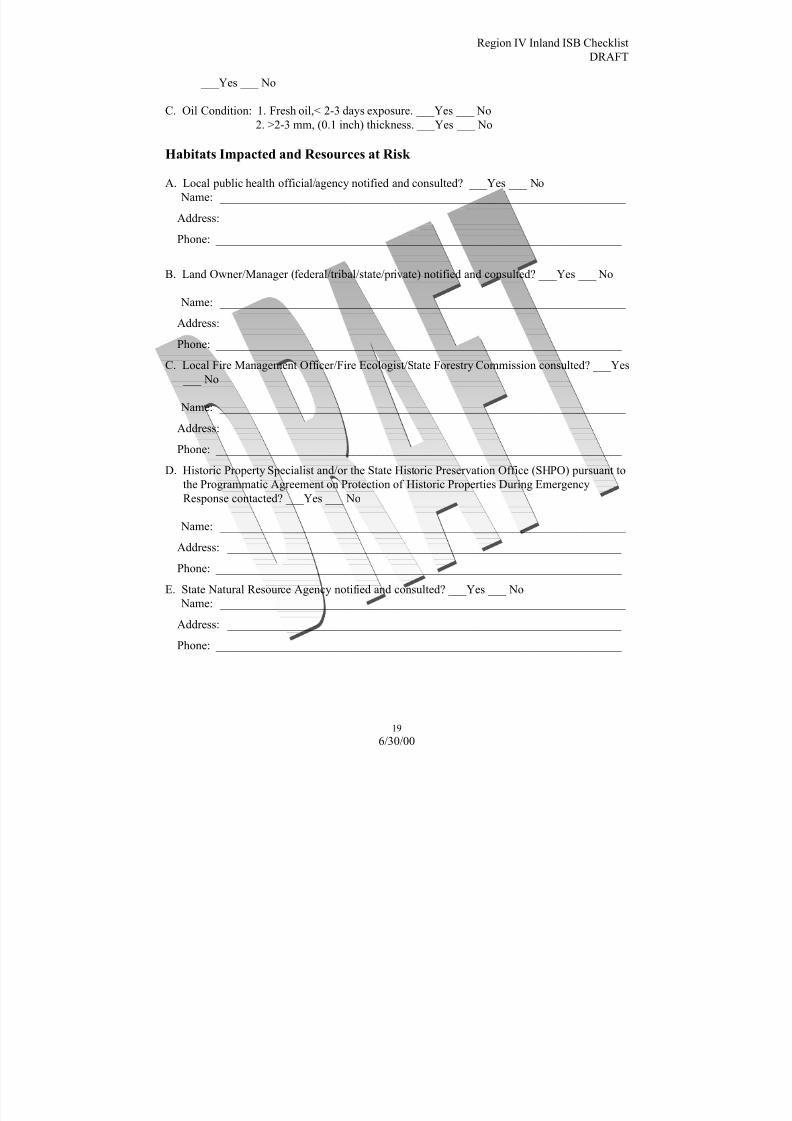
8/3/2019 Guia de selección de tecnologias aplicadas a derrames Vol II
http://slidepdf.com/reader/full/guia-de-seleccion-de-tecnologias-aplicadas-a-derrames-vol-ii 215/298
Region IV Inland ISB Checklist
DRAFT
19
6/30/00
___Yes ___ No
C. Oil Condition: 1. Fresh oil,< 2-3 days exposure. ___Yes ___ No
2. >2-3 mm, (0.1 inch) thickness. ___Yes ___ No
Habitats Impacted and Resources at Risk
A. Local public health official/agency notified and consulted? ___Yes ___ No
Name: ____________________________________________________________________
Address: __________________________________________________________________
Phone: ____________________________________________________________________
B. Land Owner/Manager (federal/tribal/state/private) notified and consulted? ___Yes ___ No
Name: ____________________________________________________________________
Address: __________________________________________________________________
Phone: ____________________________________________________________________
C. Local Fire Management Officer/Fire Ecologist/State Forestry Commission consulted? ___Yes
___ No
Name: ____________________________________________________________________
Address: __________________________________________________________________
Phone: ____________________________________________________________________ D. Historic Property Specialist and/or the State Historic Preservation Office (SHPO) pursuant to
the Programmatic Agreement on Protection of Historic Properties During Emergency
Response contacted? ___Yes ___ No
Name: ____________________________________________________________________
Address: __________________________________________________________________
Phone: ____________________________________________________________________
E. State Natural Resource Agency notified and consulted? ___Yes ___ No
Name: ____________________________________________________________________
Address: __________________________________________________________________
Phone: ____________________________________________________________________

8/3/2019 Guia de selección de tecnologias aplicadas a derrames Vol II
http://slidepdf.com/reader/full/guia-de-seleccion-de-tecnologias-aplicadas-a-derrames-vol-ii 216/298
Region IV Inland ISB Checklist
DRAFT
20
6/30/00
F. Federal Natural Resource Trustees notified and consulted
□ Department of the Interior □ Department of Defense
□ Tennessee Valley Authority □ National Aeronautic and Space
Administration
□ U.S. Forest Service □ National Oceanic and Atmospheric
Administration/ Dept of Commerce
□ Department of Energy □ Other:
G. Native American interests present? ___Yes ___ No Unknown
Tribal contact:
Name: ____________________________________________________________________
Address: __________________________________________________________________
Phone: ____________________________________________________________________
Bureau of Indian Affairs contact:
Name: ____________________________________________________________________
Address: __________________________________________________________________
Phone: ____________________________________________________________________
H. Surface water intakes and wells (public and private): ___Yes ___ No
I. Habitat Type(s) Impacted:
□ Southern cordgrass prairie □ Wetlands
□ Estuarine □ Lacustrine
□ Riverine □ Palustrine
□ Palmetto prairie □ Agricultural lands
□ Cypress savanna □ Other (specify):
J. Seasonal concerns: ___Yes ___ No
Comments: ________________________________________________________________

8/3/2019 Guia de selección de tecnologias aplicadas a derrames Vol II
http://slidepdf.com/reader/full/guia-de-seleccion-de-tecnologias-aplicadas-a-derrames-vol-ii 217/298
Region IV Inland ISB Checklist
DRAFT
21
6/30/00
K. Biological Resources Present: ________________________________________________
(Describe significant issues such as large concentrations, breeding activities, rookeries,
designated critical habitat, etc.)
□
T&E Species, including plants (list): ___________________________________________
□Mammals _________________________________________________________________
□Waterfowl _________________________________________________________________
□Wading Birds ______________________________________________________________
□ Diving Birds ______________________________________________________________
□ Shore Birds _______________________________________________________________
□ Raptors ___________________________________________________________________
□ Fish _____________________________________________________________________
□ Reptiles __________________________________________________________________
□ Amphibians _______________________________________________________________
□ Other ____________________________________________________________________
□ Comments/Attachments (i.e., ESI Maps) ________________________________________
L. Natural Areas (list)
□ National Park: _____________________________________________________________
□ National Wildlife Refuge: ____________________________________________________
□ National Forest: ____________________________________________________________
□ State Park: ________________________________________________________________
□ State Wildlife Area: _________________________________________________________
□ Other Natural Areas:_________________________________________________________
□ Comments ________________________________________________________________
M. Historic, Cultural, and Archeological Resources
□ Unknown
□ Not Present
□ Present
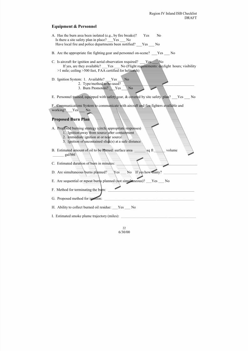
8/3/2019 Guia de selección de tecnologias aplicadas a derrames Vol II
http://slidepdf.com/reader/full/guia-de-seleccion-de-tecnologias-aplicadas-a-derrames-vol-ii 218/298
Region IV Inland ISB Checklist
DRAFT
22
6/30/00
Equipment & Personnel
A. Has the burn area been isolated (e.g., by fire breaks)? ___Yes ___ No
Is there a site safety plan in place? ___Yes ___ No
Have local fire and police departments been notified? ___Yes ___ No
B. Are the appropriate fire fighting gear and personnel on-scene? ___Yes ___ No
C. Is aircraft for ignition and aerial observation required? ___Yes ___ No
If yes, are they available? ___Yes ___ No (Flight requirements: daylight hours; visibility
>1 mile; ceiling >500 feet, FAA certified for helitorch)
D. Ignition System: 1. Available? ___Yes ___ No
2. Type/method to be-used? ______________________________________
3. Burn Promoters? ___Yes ___ No
E. Personnel trained, equipped with safety gear, & covered by site safety plan? ___Yes ___ No
F. Communications System to communicate with aircraft and fire fighters available and
working? ___Yes ___ No
Proposed Burn Plan
A. Proposed burning strategy (circle appropriate responses)
1. Ignition away from source after containment
2. Immediate ignition at or near source
3. Ignition of uncontained slick(s) at a safe distance
B. Estimated amount of oil to be burned: surface area ______ sq ft ______ volume
______ gal/bbl
C. Estimated duration of burn in minutes: ___________________________________________
D. Are simultaneous burns planned? ___Yes ___ No If yes how many? __________________
E. Are sequential or repeat burns planned (not simultaneous)? ___Yes ___ No
F. Method for terminating the burn: ______________________________________________
G. Proposed method for ignition: ________________________________________________
H. Ability to collect burned oil residue: ___Yes ___ No
I. Estimated smoke plume trajectory (miles): ________________________________________

8/3/2019 Guia de selección de tecnologias aplicadas a derrames Vol II
http://slidepdf.com/reader/full/guia-de-seleccion-de-tecnologias-aplicadas-a-derrames-vol-ii 219/298
Region IV Inland ISB Checklist
DRAFT
23
6/30/00
J. Monitoring protocols contained in SMART will be applied as appropriate. Is additional
monitoring required? ___Yes ___ No If yes, attach additional monitoring needs and specify
responsible agency.
STEP 3: IS BURNING ACCEPTABLE?
Evaluation of Anticipated Emissions
A. Using an appropriate chart, plot and calculate the following locations and distances:
1. Location of proposed burn in reference to source.
2. If on water, location of proposed burn in reference to nearest ignitable oil slick.
3. Location of proposed burn in reference to nearby human habitation/use areas,(e.g. towns,
recreational use areas, airports/strips, roads, day care centers, schools, hospitals, etc.).
B. Populations of special concern:
□ Schools □ Nursing/convalescence homes
□ Hospitals □ Day care centers
□ Retirement communities □ Other
C. Determine the following:
□ Other Distance between proposed burn and spill source (miles)□ Other Distance between burn and human habitation/use area (miles)
□ Other. Surface area of the proposed burn or burns sqft (approx.)
□ Other Will impairment of visibility affect airports and/or highways? ___Yes ___ No
D. Can burning be conducted in a controlled fashion? ___Yes ___ No
Explain measures to reduce and/or control secondary fires.
E. Using a distance of miles with the forecasted wind and transport wind direction, plot
the estimated smoke plume with particulate concentration >150 ug/m3.
F. Are additional pollutants of concern present in the smoke plum? ___Yes ___ No
If yes, what are the projected concentrations to human habitation areas? Consultation with
local air and health authorities may be necessary.
G. Will the anticipated smoke plume disperse before reaching populated areas? ___Yes ___ No

8/3/2019 Guia de selección de tecnologias aplicadas a derrames Vol II
http://slidepdf.com/reader/full/guia-de-seleccion-de-tecnologias-aplicadas-a-derrames-vol-ii 220/298
Region IV Inland ISB Checklist
DRAFT
24
6/30/00
Determination of Acceptability
A. Does the estimated smoke plume impact a populated area with particulate concentrations
averaged over one hour exceeding 150 ug/m3? ___Yes ___ No
If No, Burning is Acceptable, proceed to Step 4.
If Yes, continue with B.
B. Can the impacted population be temporarily relocated prior to burn? ___Yes ___ No
If Yes, initiate warning or evacuation and authorize burning AFTER
population is protected, proceed to Step 4. If No. do NOT authorize
burning!
STEP 4: CONTROLS & CONDITIONS
Operational Controls, Required for All Burns
A. Forecasted weather, winds and atmospheric stability class obtained? ___Yes ___ No
B. A trial burn may be necessary to observe and confirm anticipated smoke plume behavior.
Trial burns must have RRT approval.
C. Safe downwind distance validated, or expanded if winds are inconsistent with anticipated
forecast?
___Yes ___ No
D. Burn extinguishing measures in place and available? ___Yes ___ No
Public Notifications
Public notification (e.g. radio broadcast to public, safety zone broadcast to mariners, road
closure, etc.) implemented? ___Yes ___ No

8/3/2019 Guia de selección de tecnologias aplicadas a derrames Vol II
http://slidepdf.com/reader/full/guia-de-seleccion-de-tecnologias-aplicadas-a-derrames-vol-ii 221/298
Region IV Inland ISB Checklist
DRAFT
25
6/30/00
Unified Command Request to the RRT For In-situ Burning
Additional conditions that apply: ___Yes (Attached) ___ No
________________________________ _______________________
Signature of Federal On-Scene Coordinator Printed Name
________________________________ _______________________
Signature of State On-Scene Coordinator Printed Name
Does Land Owner/Manager Concur? ___Yes ___ No
________________________________ _______________________
Signature of Land Owner/Manager Printed Name

8/3/2019 Guia de selección de tecnologias aplicadas a derrames Vol II
http://slidepdf.com/reader/full/guia-de-seleccion-de-tecnologias-aplicadas-a-derrames-vol-ii 222/298
Region IV Inland ISB Checklist
DRAFT
26
6/30/00
RRT Decision Regarding In-situ Burning
A. Do not conduct in-situ burn
B. In-situ burning may be conducted pursuant to attached conditions
C. In-situ burning may be conducted as requested in Step #3
________________________________ _______________________
Signature of EPA Co-Chair Printed Name
________________________________ _______________________
Signature of USCG Co-Chair Printed Name
________________________________ _______________________
Signature of DOI Representative Printed Name
________________________________ _______________________
Signature of Affected State(s) Printed Name
________________________________ _______________________
Signature of Other Federal Trustee(s) Printed Name
________________________________ _______________________
Signature of Tribal Representative Printed Name

8/3/2019 Guia de selección de tecnologias aplicadas a derrames Vol II
http://slidepdf.com/reader/full/guia-de-seleccion-de-tecnologias-aplicadas-a-derrames-vol-ii 223/298
1
6/30/00
MMOONNIITTOOR R IINNGG PPLLAANNSS//SSTTR R AATTEEGGIIEESS
Introduction This section of the Selection Guide provides the decision-maker
with a placeholder for copies of all monitoring plans and
strategies developed by the Regional Response Team.
As of this revision date, the Regional Response Team has adoptedthe Scientific Monitoring of Applied Response Technologies
(SMART) tiered approach as guidance for dispersant and in situ
burning operations in the Region. As additional monitoring plans
and strategies are adopted by the Region, they can be added to this
section of the Selection Guide to provide the decision-maker with
a paper resource that provides complete documentation of all
support documents necessary for response decision-making.

8/3/2019 Guia de selección de tecnologias aplicadas a derrames Vol II
http://slidepdf.com/reader/full/guia-de-seleccion-de-tecnologias-aplicadas-a-derrames-vol-ii 224/298
2
6/30/00
This page intentionally left blank

8/3/2019 Guia de selección de tecnologias aplicadas a derrames Vol II
http://slidepdf.com/reader/full/guia-de-seleccion-de-tecnologias-aplicadas-a-derrames-vol-ii 225/298
v. 1/2000
SPECIAL
MONITORING of
APPLIED
RESPONSE
TECHNOLOGIES
Developed by:
U.S. Coast GuardNational Oceanic and Atmospheric Administration
U.S. Environmental Protection Agency
Centers for Disease Control and Prevention
Smoke rising from the New Carissa, February 1999. Photo by USCG

8/3/2019 Guia de selección de tecnologias aplicadas a derrames Vol II
http://slidepdf.com/reader/full/guia-de-seleccion-de-tecnologias-aplicadas-a-derrames-vol-ii 226/298
v. 1/2000
SMART is a living documentSMART is a living document. We expect that changing technologies, accumulatedexperience, and operational improvements will bring about changes to the SMARTprogram and to the document. We would welcome any comment or suggestion you mayhave to improve the SMART program.
Please send your comments to:
SMART MailNOAA OR&R7600 Sand Point Way N.E.Seattle, WA 98115USA
Fax: (206) 526-6329
Or email to:[email protected]
SMART approval statusAs of January, 2000 EPA Regions II, III, and VI adopted SMART. It was reviewed andapproved by the Science and Technology committee of the National Response Team, andwill be forwarded to the full NRT for review and approval.
AcknowledgmentsGracious thanks are extended to the members of the SMART workgroup for their tirelessefforts to generate this document, to the many reviewers who provided insightfulcomments, and to the NOAA OR&R Technical Information Group for assistance ineditorial and graphic design.
SMART is a Guidance Document Only
Purpose and Use of this Guidance:This manual and any internal procedures adopted for its implementation are intended solelyas guidance. They do not constitute rulemaking by any agency and may not be relied uponto create right or benefit, substantive or procedural, enforceable by law or in equity, by anyperson. Any agency or person may take action at variance with this manual or its internalimplementing procedures. Mention of trade names or commercial products does notconstitute endorsement or recommendation for their use by the USCG, NOAA, EPA,CDC, or the Government of the United States of America.

8/3/2019 Guia de selección de tecnologias aplicadas a derrames Vol II
http://slidepdf.com/reader/full/guia-de-seleccion-de-tecnologias-aplicadas-a-derrames-vol-ii 227/298
v. 1/2000
INTRODUCTION . . . . . . . . . . .. . . . . . . . . . . .. . . . . . . . . . .. . . . . . . . . . .. . . . . . . . . . . .. . . . . . . . . . .. . . . . . . . . 1
MONITORING DISPERSANT OPERATIONS . . . . . . . . . . .. . . . . . . . . . . .. . . . . . . . . . .. 31. BACKGROUND. . . . . . . . . . .. . . . . . . . . . . .. . . . . . . . . . .. . . . . . . . . . .. . . . . . . . . . . .. . . . . . . . . . .. . . . . . . 32. MONITORING PROCEDURES . . . . . . . . . . .. . . . . . . . . . . .. . . . . . . . . . .. . . . . . . . . . .. . . . . . . 4
2.1 Tier I: Visual Observations........... . . . . . . . . . . . . . . . . . . . . . . . . . . . . . . . . . . . . . . . . . . 4
2.2 Tier II: Fluorometry for Efficacy .... .... .... .... ..... .... .... .... ..... .... .... 42.3 Tier III: Additional Monitoring.... .... .... .... ..... .... .... .... .... ..... .... .. 52.4 Mobilizing Monitoring Resources.... .... .... .... .... .... .... .... ..... .... .... 62.5 Using and Interpreting Monitoring Results ... ... ... ... ... ... ... ... ... ... ... . 62.6 SMART as Part of the ICS Organization .... .... .... .... .... .... .... ..... .... 62.7 Information Flow and Data Handling.... .... .... .... .... .... .... ..... .... .... 7
3 . ATTACHMENTS . . . . . . . . . . . .. . . . . . . . . . .. . . . . . . . . . . .. . . . . . . . . . .. . . . . . . . . . .. . . . . . . . . . . 83.1 Roles and Responsibilities ........... . . . . . . . . . . . . . . . . . . . . . . . . . . . . . . . . . . . . . . . . . . 93.2 Command, Control, and Data Flow.... .... .... .... .... .... .... .... ..... .... .. 103.3 Dispersant Observation General Guidelines... ... ... ... ... ... ... ... ... ... ... . 113.4 Dispersant Observation Training Outline ... ... ... ... ... ... ... ... ... ... ... ... . 133.5 Dispersant Observation Checklist .... .... .... .... .... .... .... .... ..... .... .... 14
3.6 Dispersant Observation Pre-Flight List ... ... ... ... ... ... ... ... ... ... ... ... ... 153.7 Dispersant Observation Reporting Form .... .... .... .... .... .... .... ..... .... 163.8 Fluorometry Monitoring Training Outline.. ... ... ... ... ... ... ... ... ... ... ... . 173.9 Dispersant Monitoring Job Aid Checklist ... ... ... ... ... ... ... ... ... ... ... ... 193.10 Dispersant Monitoring Equipment List ... ... ... ... ... ... ... ... ... ... ... ... ... 213.11 Fluorometer Setup............ . . . . . . . . . . . . . . . . . . . . . . . . . . . . . . . . . . . . . . . . . . . . . . . . . . . 223.12 Dispersant Monitoring Field Guidelines.. ... ... ... ... ... ... ... ... ... ... ... ... 293.13 Dispersant Monitoring Water Sampling ... ... ... ... ... ... ... ... ... ... ... ... .. 343.14 Dispersant Monitoring Recorder Form ... ... ... ... ... ... ... ... ... ... ... ... ... 36
MONITORING IN SITU BURNING OPERATIONS . . . . . . . . . . .. . . . . . . . . . .. . . . . . . 371 . BACKGROUND. . . . . . . . . . . .. . . . . . . . . . .. . . . . . . . . . . .. . . . . . . . . . .. . . . . . . . . . . .. . . . . . . . . . .. 372 . MONITORING PROCEDURES . . . . . . . . . . . .. . . . . . . . . . .. . . . . . . . . . . .. . . . . . . . . . .. 37
2.1 General Considerations........... . . . . . . . . . . . . . . . . . . . . . . . . . . . . . . . . . . . . . . . . . . . . . . 372.2 Sampling and Reporting............ . . . . . . . . . . . . . . . . . . . . . . . . . . . . . . . . . . . . . . . . . . . . 372.3 Monitoring Locations ........... . . . . . . . . . . . . . . . . . . . . . . . . . . . . . . . . . . . . . . . . . . . . . . . . 382.4 Level of Concern.. . . . . . . . . . . . . . . . . . . .. . . . . . . . . . . .. . . . . . . . . . .. . . . . . . . . . .. . . . . . . . . 382.5 SMART as Part of the ICS Organization .... .... .... .... .... .... .... ..... .... 392.6 Information Flow and Data Handling.... .... .... .... .... .... .... .... ..... .... 39
3. ATTACHMENTS . . . . . . . . . . .. . . . . . . . . . .. . . . . . . . . . . .. . . . . . . . . . .. . . . . . . . . . . .. . . . . . . . . . .. . . . . 403.1 Roles and Responsibilities ........... . . . . . . . . . . . . . . . . . . . . . . . . . . . . . . . . . . . . . . . . . . 413.2 Command, Control, and Data Flow.... .... .... .... .... .... .... .... ..... .... .. 423.3 ISB Monitoring Training Outline.... .... .... .... ..... .... .... .... ..... .... .... 433.4 ISB Monitoring Job Aid Checklist .... .... .... ..... .... .... .... .... ..... .... .. 453.5 ISB Monitoring Equipment List .... .... .... .... .... .... .... .... .... ..... .... .. 473.6 ISB Monitoring DataRAM Setup.... .... .... .... ..... .... .... .... ..... .... .... 483.7 ISB Monitoring Possible Locations.... .... .... .... .... .... .... .... ..... .... .. 503.8 ISB Monitoring Recorder Sheet .... .... .... .... .... .... .... .... .... ..... .... .. 513.9 ISB Monitoring Data Sample: Graph .... .... .... .... .... .... .... .... ..... .... 52

8/3/2019 Guia de selección de tecnologias aplicadas a derrames Vol II
http://slidepdf.com/reader/full/guia-de-seleccion-de-tecnologias-aplicadas-a-derrames-vol-ii 228/298
v. 1/2000
1
INTRODUCTIONThe need for protocols to monitor response technologies during oil spills has beenrecognized since the early 1980s. Technological advances in dispersant applications and insitu burning (referred to as applied response technologies) have resulted in their increasedacceptance in several regions in the U.S. Many regions have set up pre-approval zones fordispersant and in-situ burn operations, and established pre-approval conditions, including
the requirement for monitoring protocols. This reaffirms the need for developing nationalprotocols to standardize monitoring, especially when the Federal Government assumes fullresponsibility for the response under the National Oil and Hazardous Substances PollutionContingency Plan. Protocols are also needed to serve as guidelines for assisting oroverseeing industry's monitoring efforts during spills.
In November 1997, a workgroup consisting of Federal oil spill scientists and respondersfrom the U.S. Coast Guard, the National Oceanic and Atmospheric Administration, theU.S. Environmental Protection Agency, and the Centers for Disease Control andPrevention, convened in Mobile, Alabama to draft guidelines for generating this protocol.The workgroup built upon currently available programs and procedures, mainly the SpecialResponse Operations Monitoring Program (SROMP), developed in 1994, and lessonslearned during spill responses and drills. The result of this collaboration is the Special
Monitoring of Applied Response Technologies (SMART) program.
SMART establishes a monitoring system for rapid collection and reporting of real-time,scientifically based information, in order to assist the Unified Command with decision-making during in situ burning or dispersant operations. SMART recommends monitoringmethods, equipment, personnel training, and command and control procedures that strike abalance between the operational demand for rapid response and the Unified Command'sneed for feedback from the field in order to make informed decisions.
SMART is not limited to oil spills. It can be adapted to hazardous substance responseswhere particulates air emission should be monitored, and to hydrocarbon-based chemicalspills into fresh or marine water.
General Information on SMART Modules
A. General Considerations and AssumptionsSeveral considerations guided the workgroup in developing the SMART guidelines:
1. SMART is designed for use at oil spills both inland and in coastal zones, asdescribed in the National Oil and Hazardous Substances Pollution ContingencyPlan (40 CFR Part 300).
2. SMART does not directly address the health and safety of spill responders ormonitoring personnel, since this is covered by the general site safety plan for theincident (as required by 29 CFR 1910.120).
3. SMART does not provide complete training on monitoring for a specifictechnology. Rather, the program assumes that monitoring personnel are fullytrained and qualified to use the equipment and techniques mentioned and to followthe SMART guidelines.
4. SMART attempts to balance feasible and operationally efficient monitoring withsolid scientific principles.

8/3/2019 Guia de selección de tecnologias aplicadas a derrames Vol II
http://slidepdf.com/reader/full/guia-de-seleccion-de-tecnologias-aplicadas-a-derrames-vol-ii 229/298
v. 1/2000
2
5. In general, SMART guidelines are based on the roles and capabilities of availableFederal, state, and local teams, and NOAA's Scientific Support Coordinators(SSC). The SSC is often referred to in the document as Technical Specialist. Usersmay adopt and modify the modules to address specific needs.
6. SMART uses the best available technology that is operationally feasible. The
SMART modules represent a living document and will be revised and improvedbased on lessons learned from the field, advances in technology, and developmentsin techniques.
7 . SMART should not be construed as a regulatory requirement. It is an optionavailable for the Unified Command to assist in decision-making. While every effortshould be made to implement SMART or parts of it in a timely manner, in situburning or dispersant application should not be delayed to allow thedeployment of the SMART teams.
8. SMART is not intended to supplant private efforts in monitoring responsetechnologies, but is written for adoption and adaptation by any private or publicagency. Furthermore, users may choose to tailor the modules to specific regional
needs. While currently addressing monitoring for in-situ burning and dispersantoperations, SMART will be expanded to include monitoring guidelines for otherresponse technologies.
9. It is important that the Unified Command agree on the monitoring objectives andgoals early on in an incident. This decision, like all others, should be documented.
B. OrganizationThe SMART document is arranged in modules. Each module is self-sustaining andaddresses monitoring of a single response technology. The modules are divided into threesections:
Section 1: Background Information provides a brief overview of the response technologybeing monitored, defines the primary purpose for monitoring, and discusses monitoringassumptions.
Section 2: Monitoring Procedures provide general guidelines on what, where, when, andhow to monitor; information on organization; information flow; team members; andreporting of data.
Section 3: Attachments provide detailed information to support and expand sections 1 and2.

8/3/2019 Guia de selección de tecnologias aplicadas a derrames Vol II
http://slidepdf.com/reader/full/guia-de-seleccion-de-tecnologias-aplicadas-a-derrames-vol-ii 230/298
SMART Dispersant Module v. 1/2000
3
MONITORING DISPERSANT OPERATIONS
1. BACKGROUND
1.1 Mission StatementTo provide a monitoring protocol for rapid collection of real-time, scientifically basedinformation, to assist the Unified Command with decision-making during dispersantapplications.
1. 2 Overview of DispersantsChemical dispersants combine with oil and break a surface slick into small droplets that aremixed into the water column by wind, waves, and currents. The key components of achemical dispersant are one or more surface-active agents, or surfactants. The surfactantsreduce the oil-water interfacial tension, thus requiring only a small amount of mixingenergy to increase the surface area and break the slick into droplets.
Several actions must occur for a surface oil slick to be chemically dispersed:• The surfactant must be applied to the oil in an appropriate ratio;
• The surfactant must mix with the oil or move to the oil/water interface;• The molecules must orient properly to reduce interfacial tension;• Energy (such as waves) must be applied to form oil droplets; and• The droplets must not recoalesce significantly.
Dispersants can be applied by air from airplanes and helicopters, by land usingpumping/spray systems, or by boat. They are usually applied in small droplets and in lowervolumes than the oil being treated.
1. 3 Monitoring Dispersant ApplicationWhen dispersants are used during spill response, the Unified Command needs to knowwhether the operation is effective in dispersing the oil. The SMART dispersant monitoringmodule is designed to provide the Unified Command with real-time feedback on theefficacy of dispersant application. Data collected in Tier III of the SMART dispersantprotocol may be useful for evaluating the dilution and transport of the dispersed oil.SMART does not monitor the fate, effects, or impacts of dispersed oil.
Dispersant operations and the need to monitor them vary greatly. Therefore, SMARTrecommends three levels (or tiers) of monitoring.
1. Tier I employs the simplest operation, visual monitoring.
2. Tier II combines visual monitoring with on-site water column monitoring teams that usefluorometry at a single depth with water-sample collection for later analysis.
3. Tier III expands fluorometry monitoring to several water depths, may use a portablewater laboratory, and calls for additional water samples for lab analysis
8/3/2019 Guia de selección de tecnologias aplicadas a derrames Vol II
http://slidepdf.com/reader/full/guia-de-seleccion-de-tecnologias-aplicadas-a-derrames-vol-ii 231/298
SMART Dispersant Module v. 1/2000
4
2. MONITORING PROCEDURES
2. 1 Tier I: Visual ObservationsTier I recommends visual observation by a trained observer. A trained observer, usingvisual aids, can provide a general, qualitative assessment of dispersant effectiveness. Useof guides such as the NOAA Dispersant Application Observer Job Aid is recommended for
consistency. Observations should be photographed and videotaped to help communicatethem to the Unified Command, and to better document the data for future use.
When available, visual monitoring may be enhanced by advanced sensing instruments suchas infrared thermal imaging. These and other devices can provide a higher degree of sensitivity in determining dispersant effectiveness.
Visual monitoring is relatively simple and readily done. However, visual observations donot always provide confirmation that the oil is dispersed. Tier II provides a near real-timemethod using fluorometry and water sampling.
2 .2 Tier II: Fluorometry for Efficacy
Sometimes dispersant operations effectiveness is difficult to determine by visualobservation alone. To confirm the visual observations, a monitoring team may be deployedto the dispersant application area to confirm the visual observations by using real-timemonitoring and water sampling. This is called Tier II monitoring.
Tier II monitoring uses a continuous flow fluorometer (Turner Designs™ or equivalent) atan approximately 1-meter sampling depth. The fluorometer measures the concentrations of hydrocarbons in the water column. It measures all hydrocarbons and is therefore not oil-specific. It can be used, however, to show the relative increase of hydrocarbons overbackground concentrations. This can be a good indication of oil dispersion. Tier II requireswater samples to be taken for later analysis, which will help confirm that the increasesobserved were due to dispersed oil.
A water-column monitoring team composed of at least one trained technician and a supportperson is deployed on a suitable platform. Under ideal circumstances, the team collects datain three primary target locations: (1) background water (no oil); (2) oiled surface slicksprior to dispersant application, and (3) post-application, after the oil has been treated withdispersants. Data are collected in real-time by both a built-in data-logging device and by thetechnician who monitors the readings from the instrument's digital readout and recordsthem in a sampling log. The sampling log not only provides a backup to the data logger,but allows the results to be communicated, near real-time, to the appropriate technicalspecialist in the Unified Command. Data logged by the instrument are used fordocumentation and scientific evaluation.
The field team should record the time, instrument readings, and any relevant observationsat selected time intervals. Global Positioning System (GPS) instruments are used to
ascertain the exact position of each reading.
Water samples are collected in bottles to validate and quantify the fluorometry monitoring.Samples are collected at the outlet port of the flow-through water hose, past the fluorometercell. Exact time and position are noted for each sample, for correlation with fluorometerreadings. The number of water samples taken reflects the monitoring effort. Generally, fivesamples collected for each fluorometer data run is considered adequate in addition tobackground samples. The water samples are stored in a cooler and sent to a laboratory forfuture analysis.

8/3/2019 Guia de selección de tecnologias aplicadas a derrames Vol II
http://slidepdf.com/reader/full/guia-de-seleccion-de-tecnologias-aplicadas-a-derrames-vol-ii 232/298
SMART Dispersant Module v. 1/2000
5
2 .3 Tier III: Additional MonitoringTiers I and II provide feedback to the Unified Command on the effectiveness of dispersantapplication. If dispersants are effective and additional information on the movement of thedispersed oil plume is desired, SMART Tier III procedures can address this need.
Tier III follows Tier II procedures, but collects information on the transport and dispersion
of the oil in the water column. It helps to verify that the dispersed oil is diluting towardbackground levels.
Tier III monitoring may be conducted as follows:
1. Multiple depths with one fluorometer: This monitoring technique provides a cross-section of relative concentrations of dispersed oil at different depths, measuring thedilution of dispersed oil down to background levels. When transecting the dispersant-treated slick (as outlined for Tier II) the team stops the vessel at location(s) whereelevated fluorometry readings are detected at 1 meter and, while holding position, theteam lowers the fluorometry sampling hose at several increments down to a maximumdepth of 10 meters. Readings are taken at each water depth, and the data recorded bothautomatically in the instrument data logger and manually by the monitors. Manual
readings should be taken at discreet time intervals of 2 minutes, 5 minutes, etc. asspecified by the Monitoring Group Supervisor or as indicated in a written samplingplan developed by the Dispersant Technical Specialist.
2. Transect at two different depths: This technique also looks at changes in concentrationtrends, but uses two fluorometers monitoring at different depths as the monitoringvessel transects the dispersed oil slick while making continuous observations. It isdone as follows:
Monitoring is conducted at two different depths, 1 and 5 meters, or any two waterdepths agreed upon by the Incident Commander or the Unified Command. Twosampling setups (outriggers, hoses, etc.) and two different fluorometers are used, allon a single vessel. The vessel transects the dispersant-treated slick as outlined in TierII, except that now data are collected simultaneously for two water depths. While thedata logger in each instrument automatically records the data separately, the monitoringteam manually records the data from both instrument simultaneously at discrete timeintervals of 2 minutes, 5 minutes, etc, as specified by the Monitoring GroupSupervisor or the sampling plan developed by the Dispersant Technical Specialist.Comparison of the readings at the two water depths may provide information on thedilution trend of the dispersed oil.
3. Water parameters : In addition to fluorometry data, the Unified Command may requestthat water physical and chemical parameters be measured. This can be done by using aportable lab such as the Hydrolab or similar instrument, connected in-line with thefluorometer to measure water temperature, conductivity, dissolved oxygen content,
pH, and turbidity. These data can help explain the behavior of the dispersed oil. Theturbidity data may provide additional information on increased concentrations of dispersed oil if turbidity is elevated. The other physical and chemical parametersmeasure the characteristics of the water column that could possibly affect the rate of dispersion.
4. As in Tier II, water samples are collected, but in greater numbers to help validate thefluorometer readings.

8/3/2019 Guia de selección de tecnologias aplicadas a derrames Vol II
http://slidepdf.com/reader/full/guia-de-seleccion-de-tecnologias-aplicadas-a-derrames-vol-ii 233/298
SMART Dispersant Module v. 1/2000
6
Calibration and documentation used for Tier II are valid for Tier III as well, including theuse of a check standard to verify instrument response. Because of the increased complexityof Tier III, a dispersant technical specialist (e.g., member of the scientific support team)should be on location to assist the monitoring efforts.
A critical point to keep in mind is that in the hectic and rapidly changing conditions of spill
response, flexibility and adaptability are essential for success. The sampling plan is dictatedby many factors such as the availability of equipment and personnel, on-scene conditions,and the window of opportunity for dispersant application. The need for flexibility insampling design, effort, and rapid deployment (possibly using a vessel of opportunity),may dictate the nature and extent of the monitoring. To assist the monitoring efforts, it isimportant that the unified command agrees on the goals and objectives of monitoring andchooses the Tier or combination thereof to meet the needs of the response.
2. 4 Mobilizing Monitoring ResourcesDispersant application has a narrow window of opportunity. Time is of the essence andtimely notification is critical. It is imperative that the monitoring teams and technicaladvisors are notified of possible dispersant application and SMART monitoring deploymentas soon as they are considered, even if there is uncertainty about carrying out this response
option. Prompt notification increases the likelihood of timely and orderly monitoring.
The characteristics of the spill and the use of dispersants determine the extent of themonitoring effort and, consequently, the number of teams needed for monitoring. Forsmall-scale dispersant applications, a single visual monitoring team may suffice. For largedispersant applications several visual and water-column monitoring teams may be needed.
2 .5 Using and Interpreting Monitoring ResultsProviding the Unified Command with objective information on dispersant efficacy is thegoal of Tier I and II dispersant monitoring. When visual observations and on-site watercolumn monitoring confirm that the dispersant operation is not effective, the UnifiedCommand may consider evaluating further use. If, on the other hand, visual observations
and/or fluorometry monitoring suggest that the dispersant operation is effective, dispersantuse may be continued.
When using fluorometry, the readings will not stay steady at a constant level but will varywidely, reflecting the patchiness and inconsistency of the dispersed oil plume. Personsreviewing the data should look for trends and patterns providing good indications of increased hydrocarbon concentrations above background. As a general guideline only, afluorometer signal increase in the dispersed oil plume of five times or greater over thedifference between the readings at the untreated oil slick and background (no oil) is a strongpositive indication. This should not be used as an action level for turning on or off dispersant operations. The final recommendation for turning a dispersant operation on oroff is best left to the judgment of the Technical Specialist charged with interpreting thefluorometry data. The Unified Command, in consultation with the Technical Specialist,
should agree early on as to the trend or pattern that they would consider indicative or non-indicative of a successful dispersant operation. This decision should be documented.
2 .6 SMART as Part of the ICS OrganizationSMART activities are directed by the Operations Section Chief in the Incident CommandSystem (ICS). A "group" should be formed in the Operations Section to direct themonitoring effort. The head of this group is the Monitoring Group Supervisor. Under eachgroup there are teams: Visual Monitoring Teams and Water Column Monitoring teams. At aminimum, each monitoring team consists of two trained members: a monitor and anassistant monitor. An additional team member could be used to assist with sampling and

8/3/2019 Guia de selección de tecnologias aplicadas a derrames Vol II
http://slidepdf.com/reader/full/guia-de-seleccion-de-tecnologias-aplicadas-a-derrames-vol-ii 234/298
SMART Dispersant Module v. 1/2000
7
recording. The monitor serves as the team leader. The teams report to the MonitoringGroup Supervisor, who directs and coordinates team operations, under the control of theOperations Section Chief.
Dispersant monitoring operations are very detailed. They are linked with the dispersantapplication, but from an ICS management perspective, they should be separated. Resources
for monitoring should be dedicated and not perform other operational functions.
2. 7 Information Flow and Data HandlingCommunication of monitoring results should flow from the field (Monitoring GroupSupervisor) to those persons in the Unified Command who can interpret the results and usethe data. Typically this falls under the responsibility of a Technical Specialist on dispersantsin the Planning Section of the command structure. For the U.S. Coast Guard, the technicalspecialist is the Scientific Support Coordinator. Note that the operational control of themonitoring groups remains with the Operations Section Chief, but the reporting of information is to the Technical Specialist in the Planning Section.
The observation and monitoring data will flow from the Monitoring Teams to theMonitoring Group Supervisor. The Group Supervisor forwards the data to the Technical
Specialist. The Technical Specialist or his/her representative reviews the data and, mostimportantly, formulates recommendations based on the data. The Technical Specialistcommunicates these recommendations to the Unified Command.
Quality assurance and control should be applied to the data at all levels. The TechnicalSpecialist in the Planning section is the custodian of the data during the operation. The databelong to the Unified Command. The Unified Command should ensure that the data areproperly stored, archived, and accessible for the benefit of future monitoring operations.

8/3/2019 Guia de selección de tecnologias aplicadas a derrames Vol II
http://slidepdf.com/reader/full/guia-de-seleccion-de-tecnologias-aplicadas-a-derrames-vol-ii 235/298
SMART Dispersant Module v. 1/2000
8
3. ATTACHMENTS
The following attachments are designed to assist response personnel in implementing theSMART protocol. A short description of each attachment is provided below.
Number Title Description
3.1 Roles and Responsibilities Detailed roles and responsibilities forresponders filling monitoring positions
3.2 Command, Control, and Data Flow An ICS structure for controllingmonitoring units and transferringmonitoring results
3.3 Dispersant Observation GeneralGuidelines
General guidelines for Tier Imonitoring
3.4 Dispersant Observation TrainingOutline
Outline of what should be covered forTier I observation training
3.5 Dispersant Observation Checklist Equipment and procedure checklist forTier I monitoring
3.6 Dispersant Observation Pre-Flight
List
A checklist for getting air resources
coordinated and ready for Tier Imonitoring
3.7 Dispersant Observation ReportingForm
A form for recording Tier Iobservations
3.8 Dispersant Monitoring TrainingOutline
A training outline for water columnmonitoring done in Tiers II and III
3.9 Dispersant Monitoring Job AidChecklist
A list of the tasks to accomplish before,during, and after the monitoringoperations
3.10 Dispersant Monitoring EquipmentList
A detailed equipment list forperforming Tier II and III monitoring
3.11 Fluorometer Setup A summary checklist for operating the
Turner Design fluorometer3.12 Dispersant Monitoring FieldGuidelines
Field procedures for using Tier II andIII monitoring protocols
3.13 Dispersant Monitoring WaterSampling
Procedures for collecting water samplesfor Tiers II and III
3.14 Dispersant Monitoring RecorderSheet
A form for recording fluorometerreadings for Tiers II and III

8/3/2019 Guia de selección de tecnologias aplicadas a derrames Vol II
http://slidepdf.com/reader/full/guia-de-seleccion-de-tecnologias-aplicadas-a-derrames-vol-ii 236/298
SMART Dispersant Module Attachment 1 v. 1/2000
9
3. 1 Roles and Responsibil it ies
3 .1 .1 Visual Monitoring TeamThe Visual Monitoring Team is ideally composed of two persons: a Monitor and anAssistant Monitor.
The Monitor:• Functions as the team leader• Qualitatively measures dispersant effectiveness from visual observation• Communicates results to the Group Supervisor.
The Assistant Monitor:• Provides photo and visual documentation of dispersant effectiveness• Assists the Monitor as directed.
3. 1. 2 Water-Column Monitoring TeamThe Water-Column Monitoring Team is composed of a minimum of two persons: aMonitor and Assistant Monitor. They shall perform their duties in accordance with the TierII and Tier III monitoring procedures.
The Monitor:• Functions as the team leader• Operates water-column monitoring equipment• Collects water samples for lab analysis• Communicates results to the Group Supervisor.
The Assistant Monitor:• Provides photo and visual documentation of dispersant effectiveness• Assists Monitor as directed• Completes all logs, forms, and labels for recording water column measurements, water
quality measurements, interferences, and environmental parameters.
3. 1 . 3 Monitoring Group SupervisorThe Monitoring Group Supervisor:• Directs Visual Monitoring and Water Column Monitoring teams to accomplish their
responsibilities• Follows directions provided by the Operations Section in the ICS• Communicates monitoring results to the Technical Specialist in the Planning Section• The Monitoring Group Supervisor may not be needed for a Tier I deployment. In these
cases, the Visual Monitoring Team monitor may perform the duties of the MonitoringGroup Supervisor.
3 . 1 . 4 Dispersant Monitoring Technical Specialist (Federal: NOAASSC)
The Technical Specialist or his/her representative:• Establishes communication with the Monitoring Group Supervisor• Advises the Group Supervisor on team placement and data collection procedures• Receives the data from the Group Supervisor• Ensures QA/QC of the data, and analyzes the data in the context of other available
information and incident-specific conditions• Formulates recommendations and forwards them to the Unified Command• Makes the recommendations and data available to other entities in the ICS• Archives the data for later use, prepares report as needed.
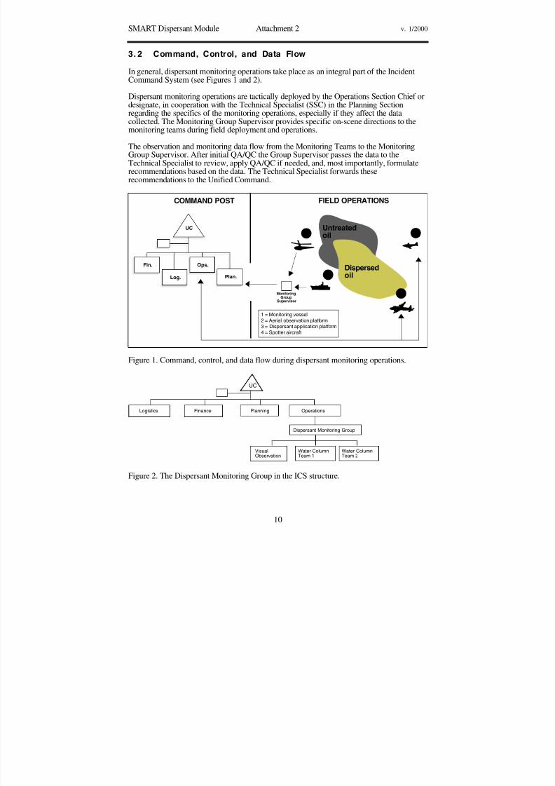
8/3/2019 Guia de selección de tecnologias aplicadas a derrames Vol II
http://slidepdf.com/reader/full/guia-de-seleccion-de-tecnologias-aplicadas-a-derrames-vol-ii 237/298
SMART Dispersant Module Attachment 2 v. 1/2000
10
3. 2 Command, Control, and Data Flow
In general, dispersant monitoring operations take place as an integral part of the IncidentCommand System (see Figures 1 and 2).
Dispersant monitoring operations are tactically deployed by the Operations Section Chief or
designate, in cooperation with the Technical Specialist (SSC) in the Planning Sectionregarding the specifics of the monitoring operations, especially if they affect the datacollected. The Monitoring Group Supervisor provides specific on-scene directions to themonitoring teams during field deployment and operations.
The observation and monitoring data flow from the Monitoring Teams to the MonitoringGroup Supervisor. After initial QA/QC the Group Supervisor passes the data to theTechnical Specialist to review, apply QA/QC if needed, and, most importantly, formulaterecommendations based on the data. The Technical Specialist forwards theserecommendations to the Unified Command.
Untreatedoil
COMMAND POST FIELD OPERATIONS
Dispersedoil1
2
3
4
1 = Monitoring vessel2 = Aerial observation platform3 = Dispersant application platform4 = Spotter aircraft
Fin.
Log.
Ops.
Plan.
UC
MonitoringGroup
Supervisor
Figure 1. Command, control, and data flow during dispersant monitoring operations.
Logistics Finance Planning
VisualObservation
Water ColumnTeam 1
Water ColumnTeam 2
Dispersant Monitoring Group
Operations
UC
Figure 2. The Dispersant Monitoring Group in the ICS structure.

8/3/2019 Guia de selección de tecnologias aplicadas a derrames Vol II
http://slidepdf.com/reader/full/guia-de-seleccion-de-tecnologias-aplicadas-a-derrames-vol-ii 238/298
SMART Dispersant Module Attachment 3 v. 1/2000
11
3 .3 Dispersant Observation General Guidelines
3 . 3 . 1 GoalThe goal of Tier I monitoring is to identify oil, visually assess efficacy of dispersantsapplied to oil, and report the observations to the Unified Command with recommendations.The recommendations may be to continue, to modify, or to evaluate further monitoring or
use because dispersants were not observed to be effective.
3 .3 .2 Guidelines and Pointers
3.3.2.1 Reporting Observations• The observer does not make operational decisions, e.g., how much dispersant to apply,
or when and where to apply it. These decisions are made at the command level, and theobserver makes observations based on those decisions.
• Different observers at the same site may reach different conclusions about how much of the slick has been dispersed. This is why comprehensive standard reporting criteria anduse of a common set of guidelines is important. Use of the NOAA Dispersant Application Observer Job Aid is highly encouraged.
3.3.2.2 Oil on the Water• Oil surface slicks and plumes can appear different for many reasons including oil or
product characteristics, time of day (different sun angles), weather, sea state, rate atwhich oil disperses. The use of the NOAA Open Water Oil Identification Job Aid for Aerial Observation is highly recommended.
• Low-contrast conditions (e.g., overcast, twilight, and haze) make observationsdifficult.
• For best viewing, the sun should be behind the observer and with the aircraft at analtitude of about 200 - 300 feet flying at a 30-degree angle to the slick.
3.3.2.3 Dispersant Applications• During dispersant application, it may be impossible to determine the actual area of
thickest oil concentrations, resulting in variable oil/dispersant application rates. Thiscould lead to variations in the effectiveness of application. The observer should reportthese conditions.
• Initial applications may have a herding effect on the oil. This would cause the slick toappear to be shrinking when, in fact, it is the dispersant “pushing” the oil together. Dueto this effect, in some cases, the oil slick may even disappear from the sea surface for ashort time.
• After dispersant application, there may be color changes in the emulsified slick due to
reduction in water content and viscosity, and changes in the shape of the slick, due tothe de-emulsification action of the dispersant.
• Many trials have indicated that dispersants apparently modify the spreading rates of oils, and within a few hours treated slicks cover much larger areas than control slicks.
3.3.2.4 Effective/Ineffective Applications• Dispersed oil plume formation may not be instantaneous after dispersant application. In
some cases, such as when the oil is emulsified, it can take several hours. A dispersedoil plume may not form at all.

8/3/2019 Guia de selección de tecnologias aplicadas a derrames Vol II
http://slidepdf.com/reader/full/guia-de-seleccion-de-tecnologias-aplicadas-a-derrames-vol-ii 239/298
SMART Dispersant Module Attachment 3 v. 1/2000
12
• The appearance of the dispersed plume can range from brown to white (cloudy) to novisible underwater plume (this is why Tier II may be necessary).
• Sometimes other things such as suspended solids may resemble dispersed oil.
• The visibility of the dispersed plume will vary according to water clarity. In somecases, remaining surface oil and sheen may mask oil dispersing under the slick and thusinterfere with observations of the dispersed oil plume.
• Dispersed oil plumes are often highly irregular in shape and non-uniform inconcentration. This may lead to errors in estimating dispersant efficiency.
• If a visible cloud in the water column is observed, the dispersant is working. If avisible cloud in the water column is not observed, it is difficult to determine whether thedispersant is working.
• If there are differences in the appearance between the treated slick and an untreatedslick, the dispersant may be working.
• Boat wakes through oil may appear as a successful dispersion of oil; however, this maybe just the vessel wake breaking a path through the oil (physically parting the oil), notdispersing it.

8/3/2019 Guia de selección de tecnologias aplicadas a derrames Vol II
http://slidepdf.com/reader/full/guia-de-seleccion-de-tecnologias-aplicadas-a-derrames-vol-ii 240/298
SMART Dispersant Module Attachment 4 v. 1/2000
13
3 .4 Dispersant Observation Training Outline
Below is a suggested outline for dispersant observation training.
Topics and sub-topics Duration
Observation Platforms 30 min.• Helo or fixed-wing, separate from application platform• Safety considerations: daylight; safe flying conditions• Logistical considerations: personnel; equipment; communication• Planning an overflightOil on water 1 hour
• Physical properties• Different types of oil• Chemistry, crude vs. refined product• Appearance and behavior• Effects of wind, waves, and weatherHow dispersants work 45 min.
• Method of action• Compatible/incompatible products• Appropriate environmental conditions (wave energy, temperature, salinity,
etc.)• Oil weathering• Oil slick thickness• Beaching, sinking, etc.Dispersant application systems 45 min.• Platform: boat, helo, plan• Encounter rate• Importance of droplet size• Dispersant-to-oil ratio (dosage)• Effective application
45 min.• Hitting the target• Dispersal into water column• Color changes• Herding effect• Ineffective application 30 min.• Missing the target• Oil remaining on surface• Coalescence and resurfacing• Wildlife concerns 30 min.• Identifying marine mammals and turtles• Rafting birds• Documenting observations 30 min.• Estimating surface coverage• Photographs: sun reflection effects, use of polarizing filter, videotaping• Written notes and sketches• Reporting observations 30 min.• Calibrating eyeballs• Recommended format• Information to include• Who to report to• Coordination with water-column monitoring

8/3/2019 Guia de selección de tecnologias aplicadas a derrames Vol II
http://slidepdf.com/reader/full/guia-de-seleccion-de-tecnologias-aplicadas-a-derrames-vol-ii 241/298
SMART Dispersant Module Attachment 5 v. 1/2000
14
3. 5 Dispersant Observation Checklist
Below is a dispersant observation checklist. Check √ the items/tasks accomplished.
Check √ ItemObservation AidsBasemaps / charts of the areaClipboard and notebook Pens / pencilsChecklists and reporting formsHandheld GPS with extra set of batteriesObservation job aids (Oil on Water & Dispersant Observation)Still cameraExtra filmVideo cameraBinocularsSafety Equipment
Personal flotation deviceEmergency locator beaconSurvival equipmentNOMEX coveralls (if available)Coldwater flotation suit (if water temperature requires)IntercomSafety Brief Preflight safety brief with pilotSafety features of aircraft (fire extinguishers, communications devices,emergency locator beacon, flotation release, raft, first aid kit, etc.)Emergency exit proceduresPurpose of mission
Area orientation / copy of previous overflightRoute / flight planDuration of flightPreferred altitudeLanding sitesNumber of people on missionEstimated weight of people and gearGear deployment (if needed, i.e., dye marker, current drogue)Frequency to communicate back to command post

8/3/2019 Guia de selección de tecnologias aplicadas a derrames Vol II
http://slidepdf.com/reader/full/guia-de-seleccion-de-tecnologias-aplicadas-a-derrames-vol-ii 242/298
SMART Dispersant Module Attachment 6 v. 1/2000
15
3 .6 Dispersant Observation Pre-Flight List
Spill Information
Incident Name:
Source Name:Date / Time Spill Occurred
Location of Spill: Latitude Longitude
Type of Oil Spilled: Amount of Oil Spilled:
Weather On Scene
Wind Speed and Direction
Visibility: Ceiling:
Precipitation: Sea State:
Aircraft Assignments
Title Name Call Sign ETD ETA
Spotter (s)
Sprayer (s)
Observer (s)
Monitor (s)
Supervisor
Safety Check
Check all safety equipment. Pilot conducts safety brief Entry/Exit Points
Airport Tactical Call Sign
Entry:
Exit:
Communications (complete only as needed; primary/secondary)
Observer to Spotter (air to air) VHF UHF Other
Observer to Monitor (air to vessel) VHF UHF Other
Observer to Supervisor (air to ground) VHF UHF OtherSupervisor to Monitor (ground to vessel) VHF UHF Other
Monitor to Monitor (vessel to vessel) VHF UHF Other
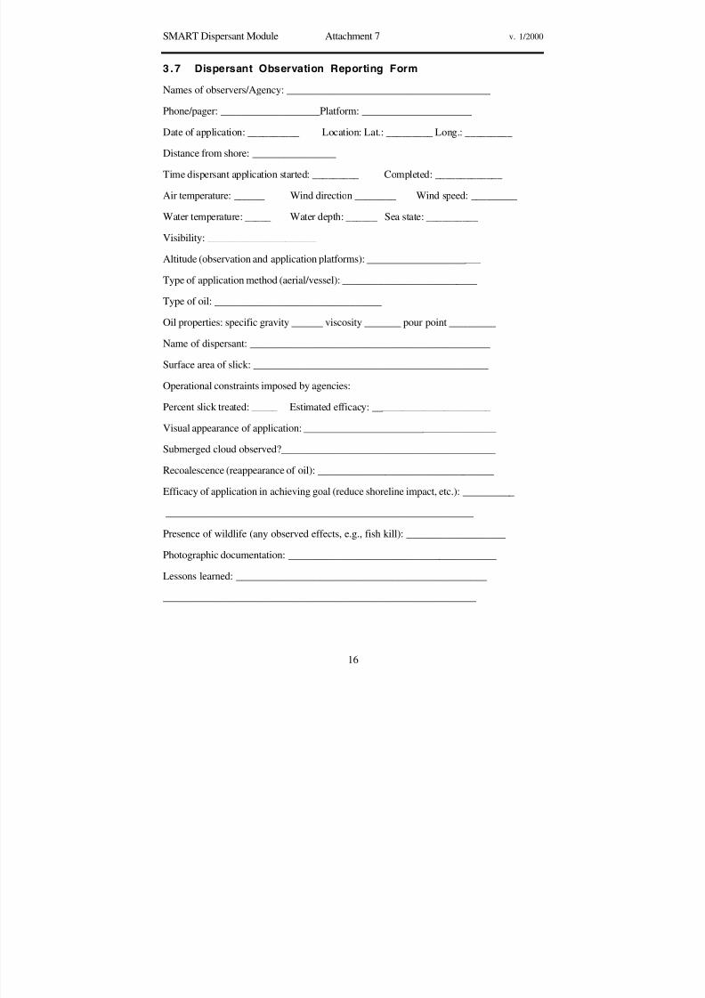
8/3/2019 Guia de selección de tecnologias aplicadas a derrames Vol II
http://slidepdf.com/reader/full/guia-de-seleccion-de-tecnologias-aplicadas-a-derrames-vol-ii 243/298
SMART Dispersant Module Attachment 7 v. 1/2000
16
3 .7 Dispersant Observation Reporting Form
Names of observers/Agency: _______________________________________
Phone/pager: ___________________Platform: _____________________
Date of application: __________ Location: Lat.: _________ Long.: _________
Distance from shore: ________________
Time dispersant application started: _________ Completed: _____________
Air temperature: ______ Wind direction ________ Wind speed: _________
Water temperature: _____ Water depth: ______ Sea state: __________
Visibility: _____________________
Altitude (observation and application platforms): ______________________
Type of application method (aerial/vessel): __________________________
Type of oil: ________________________________
Oil properties: specific gravity ______ viscosity _______ pour point _________
Name of dispersant: ______________________________________________
Surface area of slick: _____________________________________________
Operational constraints imposed by agencies: ____________________________
Percent slick treated: _____ Estimated efficacy: _______________________
Visual appearance of application: _____________________________________
Submerged cloud observed?_________________________________________
Recoalescence (reappearance of oil): __________________________________
Efficacy of application in achieving goal (reduce shoreline impact, etc.): __________
___________________________________________________________
Presence of wildlife (any observed effects, e.g., fish kill): ___________________
Photographic documentation: ________________________________________
Lessons learned: ________________________________________________
____________________________________________________________

8/3/2019 Guia de selección de tecnologias aplicadas a derrames Vol II
http://slidepdf.com/reader/full/guia-de-seleccion-de-tecnologias-aplicadas-a-derrames-vol-ii 244/298
SMART Dispersants Module Attachment 8 v. 1/2000
17
3 .8 Fluorometry Monitoring Training Outline
3 . 8 . 1 GeneralTraining for Tier II and III monitoring consists of an initial training for personnel involvedin monitoring operations, Group Supervisor training, and refresher training sessions everysix months. Emphasis is placed on field exercise and practice.
3 . 8 .2 Basic TrainingMonitor Level Training includes monitoring concepts, instrument operation, work procedures, and a field exercise.
Topic DurationBrief overview of dispersant monitoring. Review of SMART: What is it,why do it, what is it good for.
1 hour
Monitoring strategy: who, where, when. Reporting 1 hourBasic instrument operation (hands-on): how the fluorometer works, how tooperate: brief description of mechanism, setup and calibration, reading thedata, what the data mean, troubleshooting; using Global Positioning
Systems; downloading data; taking water samples
3 hours
Field exercise: Set up instruments within available boat platforms, measurebackground water readings at various locations. Using fluoroscein dye orother specified fluorescent source monitor for levels above background.Practice recording, reporting, and downloading data.
3-4 hours
3. 8 . 3 Group Supervisor TrainingGroup Supervisor training may include:• Independent training with the monitoring teams; or• An additional structured day of training as suggested below
Topic DurationReview of ICS and role of monitoring group in it, roles of Monitoring
Group Supervisor, what the data mean, QA/QC of data, command andcontrol of teams, communication, and reporting the data.
1 hour
Field exercise. Practice deploying instruments in the field with emphasison reporting, QA/QC of data, communication between teams and theGroup Supervisor, and communication with the Technical Specialist.
3-6 hours
Back to the base, practice downloading the data. 30 min.Lessons learned. 30 min.

8/3/2019 Guia de selección de tecnologias aplicadas a derrames Vol II
http://slidepdf.com/reader/full/guia-de-seleccion-de-tecnologias-aplicadas-a-derrames-vol-ii 245/298
SMART Dispersants Module Attachment 8 v. 1/2000
18
3 . 8 . 4 Refresher Training
Topic DurationReview of SMART: What is it, why do it, what is its purpose. 15 min.Monitoring and reporting: Who, where, and when; level of concern; what
the data mean; communication; and reporting the data
30-45 min.
Basic instrument operation (hands-on): how the fluorometer works and howto operate it; brief description of the mechanism, setup, calibration, readingdata, and troubleshooting; using GPS.
2 hours
Downloading data 30 min.Field exercise: Outside the classroom, set up instrument on a platform, andmeasure background readings. Using fluoroscein or other common inputsources, monitor fluorescence levels. Practice recording, reporting, anddownloading data.
1-3 hours
Lessons learned 30–45 min.
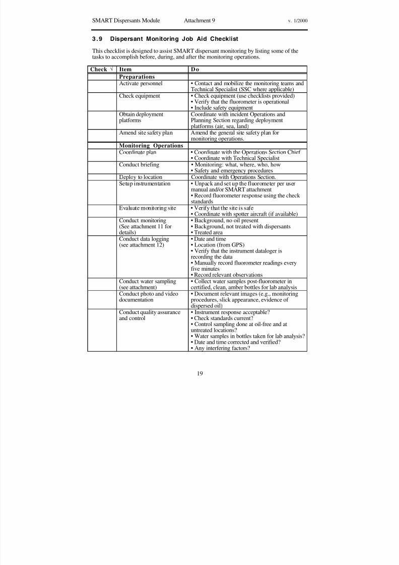
8/3/2019 Guia de selección de tecnologias aplicadas a derrames Vol II
http://slidepdf.com/reader/full/guia-de-seleccion-de-tecnologias-aplicadas-a-derrames-vol-ii 246/298
SMART Dispersants Module Attachment 9 v. 1/2000
19
3 .9 Dispersant Monitoring Job Aid Checklist
This checklist is designed to assist SMART dispersant monitoring by listing some of thetasks to accomplish before, during, and after the monitoring operations.
Check Item Do
PreparationsActivate personnel • Contact and mobilize the monitoring teams and
Technical Specialist (SSC where applicable)Check equipment • Check equipment (use checklists provided)
• Verify that the fluorometer is operational• Include safety equipment
Obtain deploymentplatforms
Coordinate with incident Operations andPlanning Section regarding deploymentplatforms (air, sea, land)
Amend site safety plan Amend the general site safety plan formonitoring operations.
Monitoring Operations
Coordinate plan • Coordinate with the Operations Section Chief • Coordinate with Technical Specialist
Conduct briefing • Monitoring: what, where, who, how• Safety and emergency procedures
Deploy to location Coordinate with Operations Section.Setup instrumentation • Unpack and set up the fluorometer per user
manual and/or SMART attachment• Record fluorometer response using the check standards
Evaluate monitoring site • Verify that the site is safe• Coordinate with spotter aircraft (if available)
Conduct monitoring
(See attachment 11 fordetails)
• Background, no oil present
• Background, not treated with dispersants• Treated areaConduct data logging(see attachment 12)
• Date and time• Location (from GPS)• Verify that the instrument dataloger isrecording the data• Manually record fluorometer readings everyfive minutes• Record relevant observations
Conduct water sampling(see attachment)
• Collect water samples post-fluorometer incertified, clean, amber bottles for lab analysis
Conduct photo and videodocumentation
• Document relevant images (e.g., monitoringprocedures, slick appearance, evidence of
dispersed oil)Conduct quality assuranceand control
• Instrument response acceptable?• Check standards current?• Control sampling done at oil-free and atuntreated locations?• Water samples in bottles taken for lab analysis?• Date and time corrected and verified?• Any interfering factors?

8/3/2019 Guia de selección de tecnologias aplicadas a derrames Vol II
http://slidepdf.com/reader/full/guia-de-seleccion-de-tecnologias-aplicadas-a-derrames-vol-ii 247/298
SMART Dispersants Module Attachment 9 v. 1/2000
20
Report (by Teams) Report to Group Supervisor:• General observation (e.g., dispersed oilvisually apparent)• Background readings• Untreated oil readings• Treated oil readings
Report (by GroupSupervisor)
Report to Technical Specialist:• General observation• Background readings• Untreated oil readings• Treated oil readings
Report by TechnicalSpecialist (SSC)
Report to Unified Command:• Dispersant effectiveness• Recommendation to continue or re-evaluate useof dispersant.
Post monitoringConduct debrief • What went right, what went wrong
• Problems and possible solutions
• Capture comments and suggestionsPreserve data • Send water samples to the lab• Download logged data from fluorometer tocomputer• Collect and review Recorder data logs• Correlate water samples to fluorometerreadings• Generate report
Prepare for next spill Clean, recharge, restock equipment

8/3/2019 Guia de selección de tecnologias aplicadas a derrames Vol II
http://slidepdf.com/reader/full/guia-de-seleccion-de-tecnologias-aplicadas-a-derrames-vol-ii 248/298
SMART Dispersants Attachment 10 v. 1/2000
21
3.10 Dispersant Monitoring Equipment List
(For each team, unless otherwise noted)Check√
Item Qty Remarks
Turner Designs™ Fluorometer 1
Carrying case 1Shipping case 1Sample injector assemblies,3-mm on-line systems
1
Long wavelength oil optical kit 2 1Internal dataloging package withelectronic chart recording
1
Power and signal cable, 12 voltsDC
1
Sampling pump 1Extension arm, rigged forfluorometer hose
1
Davis drifters 2Boat batteries, 12 volts DC, foraccessory equipment
1
Ice chest (48-quarts) for samples,with ice packs
1
Amber bottles, 1 liter 6Packing material for bottlesFittings, extra hose, repair kitCompass 1Chart of the area 1Computer and cables 1/group Should include downloading
software
Printer 1/groupRecorder data sheets 10Rite-in-the-rain notebooks, pens 3Fluorometer user manual 1Job aid check list 1GPS 1Extra batteries for GPS 1 setRadio 1Cell phone 1Binoculars 1Stop watch 1Camera 1 Digital camera or camcorder
optionalFilm 3Thermometer 1Tape measure 1

8/3/2019 Guia de selección de tecnologias aplicadas a derrames Vol II
http://slidepdf.com/reader/full/guia-de-seleccion-de-tecnologias-aplicadas-a-derrames-vol-ii 249/298
SMART Dispersant Module Attachment 11 v. 1/2000
22
3. 11 Fluorometer Setup
This is an initial operational guidance, subject to change through continued use, instrumentimprovements, local requirements, OSC needs, and scientific re-evaluation.
The Turner Designs™ Fluorometer should be maintained in an operationally ready state for
the SMART Tier II or Tier III. The following pages are step-by-step instructions to ensurethe instrument is working in an acceptable manner prior to deployment. Comments andnoted changes on the instrument's status should be documented in a maintenance log.
3 .1 1. 1. Instrument initializationTurn on by pushing red button. Opening screen with readings is called “Home” (on keypadpress “HOME”).
Verify clock time and date to GPS parameters acceptable notVerify data reading “RAW” acceptable notVerify concentration readings in “HIGH (MAN)” acceptable notVerify time constant at “2 (Sec)” acceptable not
If not acceptable, reset instrument to defaults and complete setup .
3.11,1.1 Set calibration defaultsAt “Home” screen press: <ENT> , <2> for calibration screen, <6> for defaults. Followinstructions and press “9” five times. Return to “Home” by either pressing <Home> or<ESC> back through the menu until the Home screen appears.
3.11.1.2 Set date and time to GPS parameters(Note: “logging” must not appear on the screen. If “logging” appears press: <ENT>,<5>,<3>, <ENT>. “Stop” should appear on the screen. Return to “Home.”) Once logged off from the “Home” screen press: <ENT>, <4> , and follow instructions. Press <1> to sethour, <ENT>, then <ESC>. Press <2> to set AM/PM <ENT>, then <ESC>. Press <3> to
set minutes <ENT>, then <ESC>. Press <4> to set Month <ENT>, then <ESC>. Press<5> to set Date <ENT >, then <ESC>. Press <6> to set Year <ENT>, then <ESC>.Return to the Home screen.
3.11.1.3 Set data reading to “RAW”From “Home” screen press:<ENT>, <1>, <2>, <1>. Press <ENT> until “Raw Fluorescence Data” appears on thescreen. Once found press <ESC> to save. Return to the Home screen.
3.11.1.4 Set concentration readings to “High (MAN)”From “Home” screen press: <ENT>, <2>, <4>, <3>. To change reading to “Auto,” press“<ENT> until “MAN” appears on the screen. PRESS <ESC> to save. Then press <2> for
setting range and toggle the <ENT> key until “HIGH” appears on the screen. Press<ESC> to continue and return to the Home screen.
3.11.1.5 Set time constant to “2 (Se c)”From the “Home” screen press:<ENT>, <2>, <5>, <2>. Press <ENT> to set option to two seconds. Press <ESC> tosave. Return to the Home screen.

8/3/2019 Guia de selección de tecnologias aplicadas a derrames Vol II
http://slidepdf.com/reader/full/guia-de-seleccion-de-tecnologias-aplicadas-a-derrames-vol-ii 250/298
SMART Dispersant Module Attachment 11 v. 1/2000
23
3 .1 1. 2. Instrument Sensitivity CheckTHE INSTRUMENT MUST WARM UP 10 to 15 MINUTES (FROM POWER UP) PRIOR TOCHECK!
• Verify SPAN level % at 48. acceptable____ not_____
3.11.2.1 SPAN levelFrom the “Home” screen press: <ENT>, <3>, <ENT>. In the lower portion of the screenwill be the SPAN level %. If the SPAN level is not 48%, return to the “Home” screen andfollow directions 1.1 to reset to the defaults, then return to 2.1 to read SPAN level again.Return to the Home screen. Record readings on page 6.
3.11.2.2 Fluorescein readingUsing the syringe port on the fluorometer system, drain all of the water in the cell and closethe drain. Inject 60 ml of 90 ppb fluorescein into the cell three times to flush and fill thecell. Allow instrument readings to stabilize. From the “Home” screen, press: <ENT>, <3>,<ENT>. The same screen as the SPAN level should appear. The full scale (FS) readoutshould be as close as possible to 75% of 900 and must be between 65 and 85% of 900.
If the full scale readout is not between 65 - 85%, adjust the fluorometer reading byloosening the front panel Allen screw to the left of keypad (sensitivity locking screw) withan Allen wrench. Adjust the sensitivity screw (on left panel edge, by the On/Off switch) toread as close as possible to 75% of 900. The screw setting is very sensitive, so allow timefor the instrument to stabilize. Carefully tighten the front Allen screw and recheck thereading, repeating if necessary. Record the final reading on page 6.
3 . 1 1 . 3 Instrument Calibration and Check
3.11.3.1 Setting Standard Concentration to 300 RAWFrom the “Home” screen, press: <ENT>, <2> for calibration screen, <2> for standardconcentration. Enter 300, <ENT>, then press <ESC>. Return to the Home screen.
3.11.3.2 Setting ZeroAt the “Home” screen, inject 180 ml of de-ionized water by syringe into the cell, drain,then refill and record readings. From “Home” press <ENT>, <2>, <1>, <1>. If the “blank %” is less than 200%, wait for the lower left LCD readout “TC: # (s)” to reach “8,” thenpress <0> and wait 15 seconds, then press <ESC> to save the changes. Note: If any keyother than <ESC> is pressed first, the reading will be aborted. If “blank %” is greater than200%, drain water, flush the cell with an unopened bottle of de-ionized water and recheck. If the value still remains above 200%, the cell must be cleaned. (See section 7 forcleaning.) Drain all of the water from the cell. Return to the Home screen.
3.11.3.3 Fluorometer One Point CalibrationAfter the instrument is zeroed, inject 180 ml, the fluorescein standard (at 90 ppb), into the
cell to flush and fill it. At the Home screen, allow the reading to stabilize, then press<ENT>, <2>, <3>. The screen should appear as:
RANGE HIGH MEDIUM LOWFS (RAW) 1000* 100* 10*TC: 8 (s) Range: High Span: 48%Press <*> after reading is stable
Figure 3. Screen depiction of the 1 point calibration and reading range.

8/3/2019 Guia de selección de tecnologias aplicadas a derrames Vol II
http://slidepdf.com/reader/full/guia-de-seleccion-de-tecnologias-aplicadas-a-derrames-vol-ii 251/298
SMART Dispersant Module Attachment 11 v. 1/2000
24
Note, * represents approximate values. The high scale should be around 1000 raw. Themedium and low scales are variable and will adjust to the high value.
Adjust the “span” using the up and down arrows until the FS reading for the “High” rangeis near 1000 (RAW) or slightly greater. Allow the instrument to stabilize. The lower left“TC:” value will read “8” when stable. Press <*> and wait 15 seconds. The instrument will
indicate when complete. Then press <ESC> to save changes.
*Note, <ESC> must be pressed first to save, otherwise values will be aborted. Return tothe Home screen. The reading should be 300 RAW. Drain all liquid.
3.11.3.4 Checking Blank Using the syringe port, fill the cell with 180 ml de-ionized water, drain and refill. Readingsshould be near “0 RAW” on the fluorometer screen. If the reading is greater than 1 RAW,see section 7 for cleaning procedures. Recheck with de-ionized water. Record finalreadings.
3. 11 .4 . Field Operations
3.11.4.1 Purge old dataFrom the “Home” screen, press <ENT>, <5>, <5> and follow the instructions by pressing“9” five times. The instrument will indicate data erased.
*Note, data logger must be set to “STOP” prior to erasing.
3.11.4.2 Check logging parametersFrom the “Home” screen, press: <ENT>,<5>, <2>. The screen should read:
Interval 5(sec)Method AverageStrategy <One Way>
If the parameter is different, press the appropriate number and follow the directions bytoggling settings with <ENT>.Example: Interval 3(sec)Press <1> followed be <ENT> until “5(sec)” appears on the screen.Then press <ESC>. Once parameters are correct, return Home.
3.11.4.3 Visually check Home screen1. Date and time corresponding to GPS readout2. “Raw” in upper right corner of screen3. Concentration range at “High (Man)”4. Time constant to “2(sec)”
If any readout is not correct, go to section 1.
3.11.4.4 Ready to begin logging dataBy pressing <ENT>, <5>, <5> , the screen should indicate “logging.” Return to the Homescreen and verify that the parameters in section 4.3 plus “Logging Data” appear on theupper, right-hand part of the screen.
Begin Tier II or Tier III monitoring procedures and manuallyrecord data every five minutes plus observations.

8/3/2019 Guia de selección de tecnologias aplicadas a derrames Vol II
http://slidepdf.com/reader/full/guia-de-seleccion-de-tecnologias-aplicadas-a-derrames-vol-ii 252/298
SMART Dispersant Module Attachment 11 v. 1/2000
25
3 .1 1. 5. Operational ParametersFrom the “Home” screen display, press <ENT>, <1>, then follow instructions on thescreen to change the instrument settings.
Operational Parameters Instrument Settings1. Alarm:
• Monitor alarm No2. Home Display Options
• Readout Raw Fluorescence Data• Units of measurement None
3. Bar Graph• Display bar graph Yes• Zero point 0• Full scale 999• Scale control Auto
4. Output• Full scale 2(v)
5. Serial Output
• RS-232 baud rate ++ 96006. Miscellaneous
• Beeper status On
* Note: Any parameter not listed here does not affect data when using the “dispersantmonitoring” procedure.
3 . 1 1 . 6 . Cleaning and Desiccant Procedures
3.11.6.1 CleaningDrain the water or sample from the cuvette. Take a screwdriver and remove the top metalscrew from the cuvette cell (make sure the inlet valve is closed), then fill the cell with
isopropanol. Take the cuvette brush and gently clean the cell, drain the isopropanol fromthe cell, and reinstall the metal screw. Using the syringe port, flush the cell three to fourtimes using de-ionized water. If the display reads near 0 or less, your system is clean; if not, repeat the cleaning procedure until the instrument display reads “0 Raw” or less.
3.11.6.2 DesiccantReplace desiccant once every two to three months.- Unscrew the front panel (eight Allen screws on the left side of front panel).- Replace the desiccant bag just beneath the panel
3 . 1 1 . 7 . Fluorescein Standard Preparation
3.11.7.1 Preparation of standard and stock
The 90-ppb standard was prepared from fluorescein sodium salt (70%) CAS#518-47-8. A10,000-ppm working stock solution was prepared by weighing out 143 mg of fluoresceininto 10 ml of de-ionized water in a 10-ml volumetric flask. Nine (9) microliters (µl) of theworking stock solution was added to one liter of de-ionized water in a one-liter volumetricflask to obtain the 90-ppb fluorescent standard. The 90-ppb standard should be transferredto an amber bottle so it will not photodegrade.

8/3/2019 Guia de selección de tecnologias aplicadas a derrames Vol II
http://slidepdf.com/reader/full/guia-de-seleccion-de-tecnologias-aplicadas-a-derrames-vol-ii 253/298
SMART Dispersant Module Attachment 11 v. 1/2000
26
3.11.7.2 Alternative optionAn alternative option for preparing the 90-ppb fluorescein sodium salt standard is theaddition of 486 mg of fluorescein into a 1-liter amber bottle (measured accurately) of de-ionized water. This is a 340-ppm stock standard. Agitate the 1-liter solution thoroughly toensure complete mixing, then remove 1.0 ml from the bottle into one gallon of de-ionizedwater (measured accurately). The result should be a 90-ppb fluorescent green solution. As
described above, the solution should be stored in amber glass and labeled with thepreparation date and concentration.
* Note: Weigh out the fluorescein sodium salt very quickly and tightly reseal the originalcontainer because the compound is hygroscopic (absorbs moisture). If using pre-weighedpackets, ensure that ALL material goes into the standard solution. Rinsing the containerwith de-ionized water into the bottle is strongly recommended. Standard solutions shouldbe stored in amber bottles to reduce photo-degradation of the compound. Fresh standardsshould be made every 90 days to ensure consistent results.
3. 11 .8 Downloading the DataAccess screen 5.4 and download the data. (From the main menu press <5>, then <4>.When the IBM-compatible computer is ready to receive data - press <8> five times. See
Appendix 11, section F from the instrument manual. An IBM compatible computer with themanufacturer's software program is necessary to download data from the fluorometer.
When using a PC, access the c:\ prompt, then access the Turner IDL file. EnterCD\Turner\IDL, then enter IDL_1B1. This will bring up the main menu for downloadingdata from the fluorometer. Choose steps 4 and 5 for downloading. The computer is nowready to receive data. After downloading data, choose steps 8 and 9 to review data and exitthe program.
To erase the data, access screen 5.5 and erase the data. (From the main menu press <5>,then <5>, and press <9> five times.
Figure 1. Turner Designs continuous-flow fluorometer.

8/3/2019 Guia de selección de tecnologias aplicadas a derrames Vol II
http://slidepdf.com/reader/full/guia-de-seleccion-de-tecnologias-aplicadas-a-derrames-vol-ii 254/298
SMART Dispersant Module Attachment 11 v. 1/2000
27
3 . 1 1 . 9 Fluorometer Maintenance Log Template
Fluorometer #:__________________________ Date :_______________Operator:_______________________________ Time:_______________Span FS%:_____________________________DI Water Reading:_______________________
Fluorescein Reading:_____________________Desiccant Changed:______________________
Comments:_____________________________________________________________________________________________________________________________________________________________________________________________________________________________________________________________________________________________________________________________________________________________________________________________________________________________________
***********************************************************************
Fluorometer #:__________________________ Date :_______________
Operator:_______________________________ Time:_______________Span FS%:_____________________________DI Water Reading:_______________________Fluorescein Reading:_____________________Desiccant Changed:______________________
Comments:______________________________________________________________________________________________________________________________________________________________________________________________________________________________________________________________________________________________________________________________________________________________________________________________________________________________________
***********************************************************************
Fluorometer #:__________________________ Date :_______________Operator:_______________________________ Time:_______________Span FS%:_____________________________DI Water Reading:_______________________Fluorescein Reading:_____________________Desiccant Changed:______________________
Comments:______________________________________________________________________________________________________________________________________________________________________________________________________________
________________________________________________________________________________________________________________________________________________
***********************************************************************
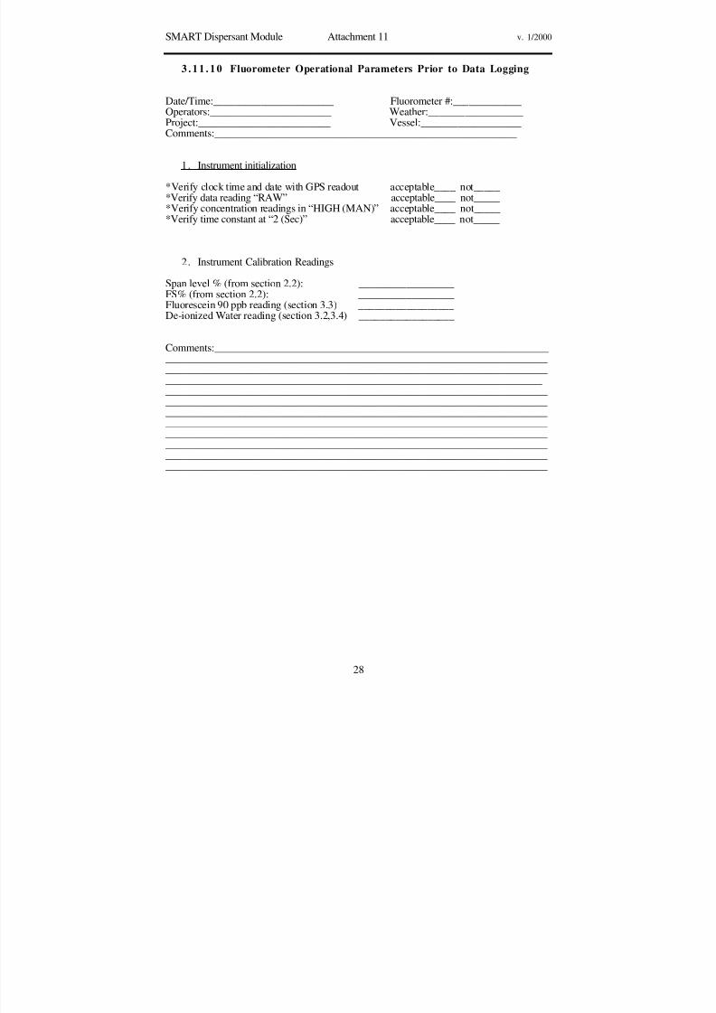
8/3/2019 Guia de selección de tecnologias aplicadas a derrames Vol II
http://slidepdf.com/reader/full/guia-de-seleccion-de-tecnologias-aplicadas-a-derrames-vol-ii 255/298
SMART Dispersant Module Attachment 11 v. 1/2000
28
3 .11 . 10 Fluorometer Operational Parameters Prior to Data Logging
Date/Time:_______________________ Fluorometer #:_____________Operators:_______________________ Weather:__________________Project:_________________________ Vessel:___________________
Comments:_________________________________________________________
1. Instrument initialization
*Verify clock time and date with GPS readout acceptable____ not_____*Verify data reading “RAW” acceptable____ not_____*Verify concentration readings in “HIGH (MAN)” acceptable____ not_____*Verify time constant at “2 (Sec)” acceptable____ not_____
2. Instrument Calibration Readings
Span level % (from section 2.2): __________________FS% (from section 2.2): __________________Fluorescein 90 ppb reading (section 3.3) __________________De-ionized Water reading (section 3.2,3.4) __________________
Comments:______________________________________________________________________________________________________________________________________________________________________________________________________________________________________________________________________________________________________________________________________________________________________________________________________________________________________________________________________________________________________________________________________________________________________________________________________________________________________________________________________________________________________________________________________________________________________________________________________________________________________________________________________________________

8/3/2019 Guia de selección de tecnologias aplicadas a derrames Vol II
http://slidepdf.com/reader/full/guia-de-seleccion-de-tecnologias-aplicadas-a-derrames-vol-ii 256/298
SMART Dispersant Module Attachment 12 v. 1/2000
29
3.12 Dispersant Monitoring Field Guidelines
3 .1 2. 1 OverviewDispersant monitoring with fluorometers employs a continuous flow fluorometer (Turner
Design™ or equivalent) at adjustable water depths. Using a portable outrigger, thesampling hose is deployed off the side of the boat and rigged so that the motion of the
boat’s propeller or the wake of the sampling boat does not disrupt the sampling line. Thefluorometer is calibrated with a check standard immediately prior to use in accordance withthe operator’s manual. In addition, water samples are collected for confirmation byconventional laboratory analysis.
3. 12 .2 Tier II Monitoring Operations
3.12.2.1 Monitoring ProceduresMonitoring the water column for dispersant efficacy includes three parts:1. Water sampling for background reading, away from the oil slick;2. Sampling for naturally dispersed oil, under the oil slick but before dispersants areapplied; and
3. Monitoring for dispersed oil under the slick area treated with dispersants.
3.12.2.2 Background sampling, no oilEn route to the sampling area and close to it, the sampling boat performs a fluorometrysampling run where there is no surface slick. This sampling run at 1-meter depth willestablish background levels before further sampling.
3.12.2.3 Background sampling, naturally dispersed oilWhen reaching the sampling area, the sampling boat makes the sampling transects at1-meter depths across the surface oil slick(s) to determine the level of natural dispersionbefore monitoring the chemical dispersion of the oil slick(s).
3.12.2.4 Fluorometry sampling of dispersed oil
After establishing background levels outside the treated area, the sampling boat interceptsthe dispersed subsurface plume. The sampling boat may have to temporarily suspendcontinuous sampling after collecting baseline values in order to move fast enough tointercept the plume. The sampling boat moves across the path of the dispersed oil plume toa point where the center of the dispersed plume can be predicted based on the size of thetreatment area and the locations of new coordinates, or on the movement of the DavisDrifters, as shown in Figures 2, 4, 5, and 6.
When conducting the monitoring, the transects consist of one or more “legs,” each legbeing as close as possible to a constant course and speed. The recommended speed is 1-2knots. The monitoring team records the vessel position at the beginning and end of eachleg.
The fluorescence data may be reviewed in real time to assess the relative enhanceddispersion of the water-soluble fraction of the oil. Figure 1 shows an example of how thecontinuous flow data may be presented.

8/3/2019 Guia de selección de tecnologias aplicadas a derrames Vol II
http://slidepdf.com/reader/full/guia-de-seleccion-de-tecnologias-aplicadas-a-derrames-vol-ii 257/298
SMART Dispersant Module Attachment 12 v. 1/2000
30
Figure 1. Example of a graphical presentation of fluorometer data.
3. 12 .3 Tier II Monitoring LocationsTwo methods are described for designating the area to be monitored.
3.12.3.1 The Box Coordinates MethodThe observation aircraft identifies the target slick or target zone for the sampling vessel by afour-corner box (Figure 2). Each corner of the box is a specific latitude/longitude, and thetarget zone is plotted on a chart or map for easy reference. The sampling vessel positionsnear the slick and configures the fluorometer sampling array. The pre-application samplingtransect crosses the narrow width of the box. After completing the sampling transect, thesampling vessel waits at a safe distance during dispersant application. Data logging maycontinue during this period. Fifteen to twenty minutes after dispersants have been applied,the observation aircraft generates a second box by providing the latitude and longitudecoordinates of the four corners corresponding to any observed dispersed oil plume. The
post-application transect is identical to the pre-application transect. If no plume is observed,the sampling vessel samples the same transect used for pre-application.
Untreatedoil
Samplingtransect
Samplingvessel
Coordinates
Oil driftDispersed
oil
PRE-APPLICATION POST-APPLICATION
Coordinates
Figure 2. The box coordinates Method.
3.12.3.2 Davis Drifter MethodTwo Davis type drifters (Figure 3) set to one meter are consecutively deployed over time bythe sampling boat at the same location to estimate the speed and direction of dispersed oil
Response
Dispersed oil
Control (background
TimeNo data

8/3/2019 Guia de selección de tecnologias aplicadas a derrames Vol II
http://slidepdf.com/reader/full/guia-de-seleccion-de-tecnologias-aplicadas-a-derrames-vol-ii 258/298
SMART Dispersant Module Attachment 12 v. 1/2000
31
movement. For this portion of the operation, the sampling boat must have LORAN or GPSnavigation capability.
1 meter
Figure 3. Davis Type Drifter set for one-meter depth.
Before dispersant application, the sampling boat is stationed upwind of the test applicationarea and the spotter aircraft deploys a smoke marker to mark the beginning of the area to betreated with dispersant. This position is recorded by GPS or LORAN instruments. (Figure4).
Area
to be
treated
with
dispersants
Untreated
surface
slick
Sampling vessel
Smoke marker
deployed from
aircraft
Figure 4. Position of sampling boat before dispersant application
After dispersant applications are completed, the Monitoring Group Supervisor directs thesampling boat to deploy the first Davis Drifter, set to one meter, at the position previouslymarked as the upper application boundary. (Figure 5). After approximately ten minutes, thesecond Davis Drifter, also set for a one-meter depth, is deployed as closely as LORAN or

8/3/2019 Guia de selección de tecnologias aplicadas a derrames Vol II
http://slidepdf.com/reader/full/guia-de-seleccion-de-tecnologias-aplicadas-a-derrames-vol-ii 259/298
SMART Dispersant Module Attachment 12 v. 1/2000
32
GPS will allow to the exact location of the first Davis Drifter. The direction and speed of the dispersed oil plume can be estimated by observing the line established by these DavisDrifters and the distance between them (Figure 6).
Deploy first
Davis Drifter
Treated
surface slick
Sampling
vessel
Figure 5. Deploying the first Davis Drifter following dispersant application.
Deploy second
Davis Drifter
at original
location of the
first drifter
First Davis Drifter
moved with
dispersed oil
Dispersed
subsurface oil
C u r r e n t f l o w
Route of
sampling
vessel
Untreated
oil drift
Figure 6. Deploying the second Davis Drifter.
3. 12 .4 Tier III Monitoring OperationsIf monitoring indicates that dispersant application is effective, the Unified Command may
request that additional monitoring be done to collect information on the transport anddilution trends of the dispersed oil. Tier III may be conducted to address this informationneed.
3.12.4.1 Multiple Depths with One FluorometerThis monitoring technique provides a cross section of relative concentrations of dispersedoil at different depths. To conduct this operation, the team stops the vessel whiletransecting the dispersant-treated slick at a location where the fluorometry monitoring at theone-meter depth indicated elevated readings. While holding steady at this location, the team

8/3/2019 Guia de selección de tecnologias aplicadas a derrames Vol II
http://slidepdf.com/reader/full/guia-de-seleccion-de-tecnologias-aplicadas-a-derrames-vol-ii 260/298
SMART Dispersant Module Attachment 12 v. 1/2000
33
lowers the fluorometer sampling hose at several increments down to approximately tenmeters (Figure 7). Monitoring is done for several minutes (2-3 minutes) for each waterdepth, and the readings recorded both automatically by the instrument's data logger andmanually by the monitoring team, in the data logging form. This monitoring mode, likeTier II, requires one vessel and one fluorometer with a team to operate it.
3.12.4.2 Simultaneous Monitoring at Two Different Depths.If two fluorometers and monitoring setups are available, the transect outlined for Tier IImay be expanded to provide fluorometry data for two water depths (one and five meters arecommonly used). Two sampling set-ups (outriggers, hoses, etc.) and two differentfluorometers are used, all on a single vessel, with enough monitoring personnel to operateboth instruments. The team transects the dispersant-treated slick as outlined in Tier II, butsimultaneously collect data for two water depths (Figure 7).
While the data logger in each instrument is automatically recording the data separately, themonitoring teams manually record the data from both instruments at the same time.Comparison of the readings at the two water depths may provide information on thedilution trend of the dispersed oil.
If requested by the Unified Command, water chemical and physical parameters may becollected by using a portable water quality lab such as Hydrolab, in-line with thefluorometer to measure water temperature, conductivity, dissolved oxygen content, pH,and turbidity. These data can help explain the behavior of the dispersed oil.
monitoring points
MONITORING AT MULTIPLE DEPTHS TRANSECT AT TWO DIFFERENT DEPTHS
dispersed
subsurface plume
Figure 7: Monitoring options for Tier III.

8/3/2019 Guia de selección de tecnologias aplicadas a derrames Vol II
http://slidepdf.com/reader/full/guia-de-seleccion-de-tecnologias-aplicadas-a-derrames-vol-ii 261/298
SMART Dispersant Module Attachment 13 v. 1/2000
34
3.13 Dispersant Monitoring Water Sampling
3 . 1 3. 1 . PurposeCollection of water samples during Tier II and III monitoring should assist in correlatingfluorometer readings in the field to actual dispersed oil concentrations in the water column.The water samples, collected post-fluorometer (i.e., at the outlet port of the water conduit,
after it passes through the fluorometer cell) into a one-liter bottle, are analyzed at alaboratory at the end of the field operation to ascertain actual oil concentrations in the water.
The guidelines provided below are general, and should serve as an initial starting point forwater sample collection. The number of samples collected may vary, depending on theoperation and the need for verification.
3 . 1 3 . 2 . Guidelines
3.13.2.1 Equipment1. Certified pre-cleaned amber 500-ml bottles with Teflon™-lined caps.• For Tier II, a minimum of six bottles is required.• For Tier III, a minimum of thirteen bottles is required.
2. Labels for bottles documenting time and location of collection.
3. Observation notes corresponding fluorometer readings to water sample collection, andany other observations.
3.13.2.2 Procedure1. Open valve for water sample collection and allow water to run for ten seconds before
opening and filling the bottle.
2. Fill the bottle to the top and allow no headspace in bottles after sealing.
3. Label bottle with exact time of initial filling from the fluorometer clock as well assampling depth, transect, and the distance of water hose from the outflow port of thefluorometer to the actual collection point of the water sample (to account for residencetime of water in the hose)
4. Store filled bottles in a cooler with ice while on the monitoring vessel. Keeprefrigerated (do not freeze) after returning to shore and send to the laboratory as soonas possible.
5. Measure and record the length of the hose between the fluorometer outlet and the bottleend, hose diameter, and flow rate (by filling a bucket). This will assist in accuratelylinking water sample results to fluorometer readings.
3.13.2.3 Number of Samples1. Collect one water sample per monitoring depth during the background (no oil)transect. The fluorometer readings prior to collection should be relatively constant.
2. Collect two samples per monitoring depth during the pre-dispersant monitoring (underuntreated oil slick). Try to collect water samples correlating with representativefluorometer values obtained.

8/3/2019 Guia de selección de tecnologias aplicadas a derrames Vol II
http://slidepdf.com/reader/full/guia-de-seleccion-de-tecnologias-aplicadas-a-derrames-vol-ii 262/298
SMART Dispersant Module Attachment 13 v. 1/2000
35
3. Collect approximately three samples per monitoring depth during the post-dispersanttransects. These samples should represent the range of high, middle, and low valuesobtained from the fluorometer screen.
4. Label the bottles and store them in a cooler with ice. Do not freeze. Enter water samplenumber, time, and correlated fluorometer reading in the Recorder Log for future data
processing
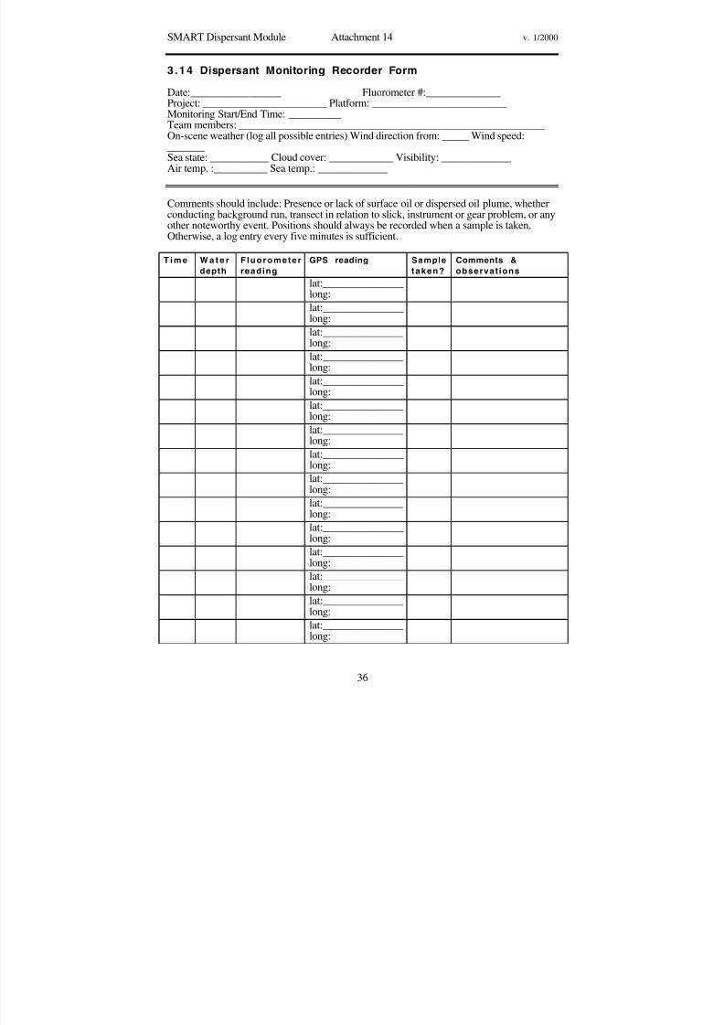
8/3/2019 Guia de selección de tecnologias aplicadas a derrames Vol II
http://slidepdf.com/reader/full/guia-de-seleccion-de-tecnologias-aplicadas-a-derrames-vol-ii 263/298
SMART Dispersant Module Attachment 14 v. 1/2000
36
3.14 Dispersant Monitoring Recorder Form
Date:_________________ Fluorometer #:______________Project: _______________________ Platform: _________________________Monitoring Start/End Time: __________Team members: _________________________________________________________
On-scene weather (log all possible entries) Wind direction from: _____ Wind speed:_______Sea state: ___________ Cloud cover: ____________ Visibility: _____________Air temp. :__________ Sea temp.: _____________
Comments should include: Presence or lack of surface oil or dispersed oil plume, whetherconducting background run, transect in relation to slick, instrument or gear problem, or anyother noteworthy event. Positions should always be recorded when a sample is taken.Otherwise, a log entry every five minutes is sufficient.
T i m e W a t e r
depth
Fluorometer
reading
GPS reading Sample
taken?
Comments &
observat ions
lat:_______________long:
lat:_______________long:
lat:_______________long:
lat:_______________long:
lat:_______________long:
lat:_______________
long:lat:_______________long:
lat:_______________long:
lat:_______________long:
lat:_______________long:
lat:_______________long:
lat:_______________long:
lat:_______________long:
lat:_______________long:
lat:_______________long:

8/3/2019 Guia de selección de tecnologias aplicadas a derrames Vol II
http://slidepdf.com/reader/full/guia-de-seleccion-de-tecnologias-aplicadas-a-derrames-vol-ii 264/298
SMART ISB Module v. 1/2000
37
MONITORING IN SITU BURNING OPERATIONS
1. BACKGROUND
1.1 Mission StatementTo provide a monitoring protocol for rapid collection of real-time, scientifically basedinformation to assist the Unified Command with decision-making during in situ burningoperations.
1. 2 Overview of In situ BurningIn situ burning of oil may offer a logistically simple, rapid, and relatively safe means forreducing the net environmental impact of an oil spill. Because a large portion of the oil isconverted to gaseous combustion products, in situ burning can substantially reduce theneed for collection, storage, transport, and disposal of recovered material. In situ burning,however, has several disadvantages: burning can take place only when the oil is notsignificantly emulsified, when wind and sea conditions are calm, and when dedicatedequipment is available. In addition, in situ burning emits a plume of black smoke,composed primarily (80-85%) of carbon dioxide and water; the remainder of the plume is
gases and particulates, mostly black carbon particulates, known as soot. These sootparticulates give the smoke its dark color. Downwind of the fire, the gases dissipate toacceptable levels relatively quickly. The main public health concern is the particulates in thesmoke plume.
With the acceptance of in situ burning as a spill response option, concerns have been raisedregarding the possible effects of the particulates in the smoke plume on the general publicdownwind. SMART is designed to address these concerns and better aid the UnifiedCommand in decisions related to initiating, continuing, or terminating in situ burning.
2 . MONITORING PROCEDURES
2.1 General ConsiderationsIn general, SMART is conducted when there is a concern that the general public may beexposed to smoke from the burning oil. It follows that monitoring should be conductedwhen the predicted trajectory of the smoke plume indicates that the smoke may reachpopulation centers, and the concentrations of smoke particulates at ground level may exceedsafe levels. Monitoring is not required, however, when impacts are not anticipated.
Execution of in situ burning has a narrow window of opportunity. It is imperative that themonitoring teams are alerted of possible in situ burning and SMART operations as soon asburning is being considered, even if implementation is not certain. This increases thelikelihood of timely and orderly SMART operations.
2. 2 Sampling and Reporting
Monitoring operations deploy one or more monitoring teams. SMART recommends at leastthree monitoring teams for large-scale burning operations. Each team uses a real-timeparticulate monitor (such as the DataRAM) capable of detecting the small particulatesemitted by the burn (ten microns in diameter or smaller), a global positioning system, andother equipment required for collecting and documenting the data. Each monitoringinstrument provides an instantaneous particulate concentration as well as the time-weightedaverage over the duration of the data collection. The readings are displayed on theinstrument’s screen and stored in its data logger. In addition, particulate concentrations arelogged manually every few minutes by the monitoring team in the recorder data log.
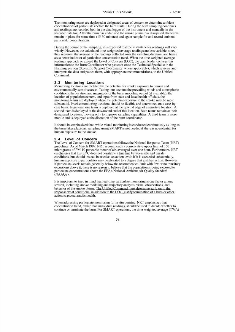
8/3/2019 Guia de selección de tecnologias aplicadas a derrames Vol II
http://slidepdf.com/reader/full/guia-de-seleccion-de-tecnologias-aplicadas-a-derrames-vol-ii 265/298
SMART ISB Module v. 1/2000
38
The monitoring teams are deployed at designated areas of concern to determine ambientconcentrations of particulates before the burn starts. During the burn sampling continuesand readings are recorded both in the data logger of the instrument and manually in therecorder data log. After the burn has ended and the smoke plume has dissipated, the teamsremain in place for some time (15-30 minutes) and again sample for and record ambientparticulate concentrations.
During the course of the sampling, it is expected that the instantaneous readings will varywidely. However, the calculated time-weighted average readings are less variable, sincethey represent the average of the readings collected over the sampling duration, and henceare a better indicator of particulate concentration trend. When the time-weighted averagereadings approach or exceed the Level of Concern (LOC), the team leader conveys thisinformation to the Burn Coordinator who passes it on to the Technical Specialist in thePlanning Section (Scientific Support Coordinator, where applicable), which reviews andinterprets the data and passes them, with appropriate recommendations, to the UnifiedCommand.
2. 3 Monitoring LocationsMonitoring locations are dictated by the potential for smoke exposure to human and
environmentally sensitive areas. Taking into account the prevailing winds and atmosphericconditions, the location and magnitude of the burn, modeling output (if available), thelocation of population centers, and input from state and local health officials, themonitoring teams are deployed where the potential exposure to the smoke may be mostsubstantial. Precise monitoring locations should be flexible and determined on a case-by-case basis. In general, one team is deployed at the upwind edge of a sensitive location. Asecond team is deployed at the downwind end of this location. Both teams remain at theirdesignated locations, moving only to improve sampling capabilities. A third team is moremobile and is deployed at the discretion of the burn coordinator.
It should be emphasized that, while visual monitoring is conducted continuously as long asthe burn takes place, air sampling using SMART is not needed if there is no potential forhuman exposure to the smoke.
2.4 Level of ConcernThe Level of Concern for SMART operations follows the National Response Team (NRT)guidelines. As of March 1999, NRT recommends a conservative upper limit of 150micrograms of PM-10 per cubic meter of air, averaged over one hour. Furthermore, NRTemphasizes that this LOC does not constitute a fine line between safe and unsafeconditions, but should instead be used as an action level: If it is exceeded substantially,human exposure to particulates may be elevated to a degree that justifies action. However,if particulate levels remain generally below the recommended limit with few or no transitoryexcursions above it, there is no reason to believe that the population is being exposed toparticulate concentrations above the EPA's National Ambient Air Quality Standard(NAAQS).
It is important to keep in mind that real-time particulate monitoring is one factor amongseveral, including smoke modeling and trajectory analysis, visual observations, andbehavior of the smoke plume. The Unified Command must determine early on in theresponse what conditions, in addition to the LOC, justify termination of a burn or otheraction to protect public health.
When addressing particulate monitoring for in situ burning, NRT emphasizes thatconcentration trend, rather than individual readings, should be used to decide whether tocontinue or terminate the burn. For SMART operations, the time-weighted average (TWA)

8/3/2019 Guia de selección de tecnologias aplicadas a derrames Vol II
http://slidepdf.com/reader/full/guia-de-seleccion-de-tecnologias-aplicadas-a-derrames-vol-ii 266/298
SMART ISB Module v. 1/2000
39
generated by the particulate monitors should be used to ascertain the trend. The NRTrecommends that burning not take place if the air quality in the region already exceeds theNAAQS and if burning the oil will add to the particulate exposure concentration. SMARTcan be used to take background readings to indicate whether the region is within theNAAQS, before the burn operation takes place. The monitoring teams should reportambient readings to the Unified Command, especially if these readings approach or exceed
the NAAQS.
2 .5 SMART as Part of the ICS OrganizationSMART activities are directed by the Operations Section Chief in the Incident CommandSystem (ICS). It is recommended that a "group" be formed in the Operations Section thatdirects the monitoring effort. The head of this group is the Monitoring Group Supervisor.Under each group there are monitoring teams. At a minimum, each monitoring teamconsists of two trained members: a monitor and assistant monitor. An additional teammember could be used to assist with sampling and recording. The monitor serves as theteam leader. The teams report to the Monitoring Group Supervisor who directs andcoordinates team operations, under the control of the Operations Section Chief.
2. 6 Information Flow and Data HandlingCommunication of monitoring results should flow from the field (Monitoring GroupSupervisor) to those persons in the Unified Command who can interpret the results and usethe data. Typically, this falls under the responsibility of a Technical Specialist on in-situburning in the Planning Section of the command structure.
The observation and monitoring data will flow from the Monitoring Teams to theMonitoring Group Supervisor. The Group Supervisor forwards the data to the TechnicalSpecialist. The Technical Specialist or his/her representative reviews the data and, mostimportantly, formulates recommendations based on the data. The Technical Specialistcommunicates these recommendations to the Unified Command.
Quality assurance and control should be applied to the data at all levels. The Technical
Specialist is the custodian of the data during the operation, but ultimately the data belongsto the Unified Command. The Unified Command should ensure that the data are properlyarchived, presentable, and accessible for the benefit of future monitoring operations.

8/3/2019 Guia de selección de tecnologias aplicadas a derrames Vol II
http://slidepdf.com/reader/full/guia-de-seleccion-de-tecnologias-aplicadas-a-derrames-vol-ii 267/298
SMART ISB Module v. 1/2000
40
3. ATTACHMENTS
The following attachments are designed to assist response personnel in implementing theSMART protocol. A short description of each attachment is provided below.
Number Title Description
3.1 Roles and Responsibilities Provides detailed roles andresponsibilities for responders fillingmonitoring positions
3.2 Command, Control, and Data Flow A suggested ICS structure forcontrolling monitoring units andtransferring monitoring results
3.3 ISB Monitoring Training Outline General training guidelines for ISBmonitoring
3.4 ISB Monitoring Job Aid Checklist A checklist to assist in assemblingand deploying SMART ISBmonitoring teams
3.5 ISB Monitoring Equipment List A list of equipment needed to
perform SMART operations3.6 ISB Monitoring DataRAM Setup Abbreviated instructions for the rapidsetup of a DataRAM particulatemonitor
3.7 ISB Monitoring Recorder Sheet A template for manual recording of burn data
3.8 ISB Monitoring Possible Locations An example of monitoring locationsfor offshore ISB operations
3.9 ISB Monitoring Data Sample: Graph An example of real ISB data

8/3/2019 Guia de selección de tecnologias aplicadas a derrames Vol II
http://slidepdf.com/reader/full/guia-de-seleccion-de-tecnologias-aplicadas-a-derrames-vol-ii 268/298
SMART ISB Module Attachment 1 v. 1/2000
41
3. 1 Roles and Responsibil it ies
3 .1 .1 Team LeaderThe Team Leader• Selects specific team location• Conducts monitoring
• Ensures health and safety of team• Ensures monitoring QA/QC• Establishes communication with the group supervisor• Conveys to him/her monitoring data as needed
3. 1 . 2 Monitoring Group SupervisorThe Group Supervisor• Oversees the deployment of the teams in the group• Ensures safe operation of the teams• Ensures QA/QC of monitoring and data• Establishes communication with the field teams and the command post• Conveys to the command post particulate level trends as needed• Addresses monitoring technical and operational problems, if encountered
3 .1 .3 In-Situ Burn Technical SpecialistThe Technical Specialist or his/her representative• Establishes communication with the Monitoring Group Supervisor• Receives the data from the Group Supervisor• Ensures QA/QC of the data• Analyzes the data in the context of other available information and incident-specific
conditions, formulates recommendations to the Unified Command• Forwards the recommendations to the Unified Command• Makes the recommendations and data available to other entities in the ICS, as needed• Archives the data for later use
Role and function Training NumberMonitoring Team LeaderLeads the monitoring team
HAZWOPER. SMART MonitorTraining
3
Monitor AssistantAssists with data collection.
HAZWOPER 3
Group SupervisorCoordinates and directs teams; fieldQA/QC of data; links with UC.
SMART Monitor training. GroupSupervisor training
1 per group
Technical SpecialistOverall QA/QC of data; reads andinterprets data; providesrecommendations to the UnifiedCommand
SMART Monitor training.Scientific aspects of ISB
1 per response

8/3/2019 Guia de selección de tecnologias aplicadas a derrames Vol II
http://slidepdf.com/reader/full/guia-de-seleccion-de-tecnologias-aplicadas-a-derrames-vol-ii 269/298
SMART ISB Module Attachment 2 v. 1/2000
42
3.2 Command, Control, and Data Flow
In general, in situ burn monitoring operations take place as an integral part of the UnifiedCommand System (Figures 1 and 2).
ISB monitoring operations are directed by the Operations Section Chief or designate. The
Operations Section Chief provides the Monitoring Group Supervisor with tactical directionsand support regarding deployment, resources, communications, and general mission asadapted to the specific incident. The Operations Section consults with the ISB monitoringTechnical Specialist about the specifics of the monitoring operations, especially if theyaffect the data collected. The Monitoring Group Supervisor provides specific direction tothe monitoring teams during field deployment and operations.
The observation and monitoring data flow from the Monitoring Teams to the MonitoringGroup Supervisor. After initial QA/QC the Group Supervisor passes the data to theTechnical Specialist. The Technical Specialist or his/her representative reviews the data,applies QA/QC if needed, and, most importantly, formulates recommendations based onthe data. The Technical Specialist forwards these recommendations to the UnifiedCommand.
COMMAND POST
ISB monitoring group
Fin.Log. Ops.
Plan.
UC
Smoke plume
Team 3 Team 2 Team 1
GroupsupervisorData flow
Operationalcontrol
FIELD
Figure 1. Command, control, and data flow during in-situ burning monitoring operations.
Team 1
Planning OperationsFinance Logistics
Team 2 Team 3
ISB Monitoring Group
UC
Figure 2. ISB Monitoring Group in the ICS organization.
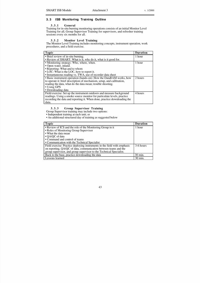
8/3/2019 Guia de selección de tecnologias aplicadas a derrames Vol II
http://slidepdf.com/reader/full/guia-de-seleccion-de-tecnologias-aplicadas-a-derrames-vol-ii 270/298
SMART ISB Module Attachment 3 v. 1/2000
43
3. 3 ISB Monitoring Training Outline
3 . 3 . 1 GeneralTraining for in-situ burning monitoring operations consists of an initial Monitor LevelTraining for all, Group Supervisor Training for supervisors, and refresher trainingsessions every six months for all.
3 .3 .2 Monitor Level TrainingThe Monitor Level Training includes monitoring concepts, instrument operation, work procedures, and a field exercise.
Topic Duration
• Brief review of in-situ burning.• Review of SMART: What is it, why do it, what is it good for.
1 hour
• Monitoring strategy: Who, where, when.• Open water, inland.• Reporting: What and to whom• LOC: What is the LOC, how to report it.
• Instantaneous reading vs. TWA, use of recorder data sheet
1 hour
• Basic instrument operation (hands-on): How the DataRAM works, howto operate it: brief description of mechanism, setup, and calibration,reading the data, what do the data mean; trouble shooting.• Using GPS• Downloading data
2 hours
Field exercise: Set up the instrument outdoors and measure backgroundreadings. Using a smoke source monitor for particulate levels, practicerecording the data and reporting it. When done, practice downloading thedata.
4 hours
3. 3 . 3 Group Supervisor TrainingGroup Supervisor training may include two options:
• Independent training at each unit; or• An additional structured day of training as suggested below
Topic Duration
• Review of ICS and the role of the Monitoring Group in it• Roles of Monitoring Group Supervisor• What the data mean• QA/QC of data• Command and control of teams• Communication with the Technical Specialist
1 hour
Field exercise: Practice deploying instruments in the field with emphasison reporting, QA/QC of data, communication between teams and the
group supervisor, and group supervisor to the Technical Specialist.
3-6 hours
Back to the base, practice downloading the data 30 min.Lessons learned 30 min.

8/3/2019 Guia de selección de tecnologias aplicadas a derrames Vol II
http://slidepdf.com/reader/full/guia-de-seleccion-de-tecnologias-aplicadas-a-derrames-vol-ii 271/298
SMART ISB Module Attachment 3 v. 1/2000
44
3 . 3 . 4 Refresher Training
Topic Duration
Review of SMART: What is it, why do it, what is it good for. 15 min.• Monitoring and reporting: Who, where, and when• Level of concern
• What do the data mean• Reporting the data• Work with the Technical Specialist (SSC).
30-45 min.
• Basic instrument operation (hands-on): How the DataRAM works, howto operate it; brief description of mechanism, setup, and calibration;• Reading the data, trouble-shooting.• Using GPS.
2 hours
Downloading data 30 min.• Field exercise: Outside the classroom, set up the instrument and measurebackground readings. Using a smoke source, monitor particulate levels.• Practice recording the data and reporting it.• Back to the base, download data.
1-2 hours

8/3/2019 Guia de selección de tecnologias aplicadas a derrames Vol II
http://slidepdf.com/reader/full/guia-de-seleccion-de-tecnologias-aplicadas-a-derrames-vol-ii 272/298
SMART ISB Module Attachment 4 v. 1/2000
45
3. 4 ISB Monitoring Job Aid Checklist
This checklist is designed to assist SMART in situ burning monitoring by listing some of the tasks to accomplish before, during, and after the monitoring operations.
Check
√
Item Do
PreparationsActivate personnel Notify monitoring personnel and the Technical
Specialist (SSC where applicable)Conduct equipment check • Check equipment using equipment checkup
list.• Verify that the DataRAMs are operational
and fully charged• Include safety equipment
Coordinate logistics Coordinate logistics (e.g., deployment platform)with ICS Operations
Amend Site Safety Plan Amend site safety plan to include monitoring
operationsMonitoring OperationsMonitoring Group setup • Coordinate with Operations Section Chief
• Coordinate with Technical SpecialistConduct Briefing • Monitoring: what, where, who, how
• Safety and emergency proceduresDeploy to location Coordinate with Operations Section Chief Select site • Safe
• Consistent with monitoring plan• As little interference as possible• Communication with Group Supervisor and
UC possible
Set up instrumentation Unpack DataRAM, set it up using instrumentsetup sheet. Verify calibrationMark position • Use GPS to mark position in recorder sheet
• Re-enter position if changing locationCollect background data Start monitoring. If possible, record background
data before the burn beginsCollect burn data • Continue monitoring as long as burn is on
• Monitor for background readings for 15-30minutes after the smoke clears
Record data Enter:• Instantaneous and TWA readings every 3-5
minutes, or other fixed intervals• Initial position from GPS, new position if
moving• Initial wind speed and direction, air
temperature, relative humidity, re-enter if conditions change

8/3/2019 Guia de selección de tecnologias aplicadas a derrames Vol II
http://slidepdf.com/reader/full/guia-de-seleccion-de-tecnologias-aplicadas-a-derrames-vol-ii 273/298
SMART ISB Module Attachment 4 v. 1/2000
46
Conduct quality assuranceand control
• Verify that instrument is logging the data• Record data, location, relative humidity,
temp, wind, interferences in the recorderdata sheet
• Note and record interference from othersources of particulates such as industry,
vehicles, vesselsReport by team Report to Group Supervisor:
• Initial background readings• TWA readings (every 15 min.)
• TWA readings when exceeding 150 µg/m3,(every 5 min.)
• Interferences• Safety problems• QA/QC and monitoring problems
Report by Group Supervisor Report to the Technical Specialist (SSC):• Initial background readings
• TWA, when exceeding 150 µg/m3
• Data QA/QC and monitoring problemsReport by TechnicalSpecialist (SSC)
Report to the Unified Command:
• TWA consistently exceeding 150 µg/m3
• Recommend go/no-go
Post MonitoringDebrief and lessons learned • What went right, what went wrong
• Problems and possible solutions• Capture comments and suggestions
Preserve data • Download logged data from DataRAM tocomputer
• Collect and review Recorder data logs• Generate report
Prepare for next burn Clean, recharge, restock equipment

8/3/2019 Guia de selección de tecnologias aplicadas a derrames Vol II
http://slidepdf.com/reader/full/guia-de-seleccion-de-tecnologias-aplicadas-a-derrames-vol-ii 274/298
SMART ISB Module Attachment 5 v. 1/2000
47
3. 5 ISB Monitoring Equipment List
(For each team, unless otherwise noted)
Check √ Item Qty Remarks
DataRAM 1
Accessories for each DataRAM:• Charger 1• Omni directional inlet 1• PM-10 inlet head 1• PM-2.5 accessory 1• Carrying/shipping cases 1• Water-resistant cover 1Other instrument: PDR andaccessoriesComputer and cables 1/group Should include downloading
softwarePrinter 1/group
Recorder data sheets 10Write-in-the-rain notebooks, pens 3DataRAM setup sheet 1Job aid check list 1GPS 1Extra batteries for GPS 1 setRadio 1Cell phone 1Binoculars 1Stop watch 1Camera 1 digital camera or camcorder
optionalFilm 3Thermometer 1Humidity meter 1Anemometer 1

8/3/2019 Guia de selección de tecnologias aplicadas a derrames Vol II
http://slidepdf.com/reader/full/guia-de-seleccion-de-tecnologias-aplicadas-a-derrames-vol-ii 275/298
SMART ISB Module Attachment 6 v. 1/2000
48
3. 6 ISB Monitoring DataRAM Setup
The following is a setup procedure to assist in field operations of the DataRAM. Words inquotation marks (e.g., “SPAN CHECK”) indicate statements on the instrument screen. SeeFigure 1 for a diagram of the DataRAM interface. Note: Instruments should be set up sideby side, turned on and calibrated simultaneously. Instruments should be synchronized with
Global Positioning System time settings.
OPERATION PROCEDURE
POWER ON Adjust 3-position locking switch on back to INT.BAT./CHARGERposition. Remove metal cap from top sampler and press the "ON"button.
CHECK BATT. Press <SYSTEM DIAGNOS> All items should read “NORMAL.”Main concern is "BATCHRG." Fully charged: 12345. Numbersdrop as battery charge decreases. Press <EXIT>, "NEXTSCREEN," <NEXT SCREEN>.
CHECK TIME See “SET DATE TIME.” If correct, press <EXIT>. If incorrect,
press <SET DATE TIME>, use the arrow keys to move through andadjust the time and date as needed. Press <EXIT>, then <EXIT>again to start the clock.
PURGE Press <PURGE>; when done purging, press <EXIT>.ZERO See "ZERO." Press <ZERO>.SPAN See "SPAN CHECK." Press <SPAN CHECK>. See "INSERT
CALIBRATOR." Insert calibrator to In position by turning SpanCheck knob in rear until it stops. See "WAIT.” Wait until the spancheck is completed. See "RETRACT CALIBRATOR." Turn theknob to out position until you hear a click. Note: Notice "CALBRDIFF" during Span Check. If the percentage is 0-10%, go toADJUST PARAMS step. If > 10%, go to the next step.
Adjusting CALBR
DIFF
Press <EXIT> <EXIT> <EXIT>, then <MENU>. Turn the
calibrator key to the In position. Wait for the RS number to settlebetween 150 and 250. Press <EXIT>, then <SYSTEM FAULT> .See "RETRACT CALIBRATOR." Turn calibrator knob to Outposition. Press <EXIT>. Repeat SPAN step.
ADJUST PARAMS See "PARAMETER" Press <PARAMETER>, to "PARAMETRS 1"screenSee "AVE TIME." Press. Scroll through options. 10 seconds is OK.See "CLEAR DATA." Press <CLEAR DATA>, <CLEAR DATA>.See "LOG DATA". Press <LOG DATA> to "ON" option.Adjust "EVERY." Use the arrow keys to adjust to 10 seconds. If adjusted, press <EXIT>, then <NEXT SCREEN>. If "EVERY" notadjusted, press <NEXT SCREEN> to "PARAMETER 2" screen
See "AUTO ZERO." Adjust to "ON".See "ALARM." Toggle to "INST." If no alarm needed, toggle to"OFF". If alarm selected see "CONC"See "CONC.” Use the arrow key to adjust the concentration to 150
µg/m3 for SMART. Press <EXIT>.See "CAL FACTOR," Press. Use the arrow keys to adjust thenumbers to 100%. <EXIT> if the calibration factor was adjusted"FLOWRATE" 2.0 lpm is OK. Toggle to adjust. <EXIT> <EXIT>

8/3/2019 Guia de selección de tecnologias aplicadas a derrames Vol II
http://slidepdf.com/reader/full/guia-de-seleccion-de-tecnologias-aplicadas-a-derrames-vol-ii 276/298
SMART ISB Module Attachment 6 v. 1/2000
49
START LOGGING "RUN DATA". Press <RUN > to start logging data. The letter "L"will appear by "MEMORY FREE" key to indicate that instrument islogging data.
ADDITIONALDATA OPTIONS
Press the menu button. "RUN MENU" screen is on. Press <ScrollData Log>. "SCROLL DATA LOG" screen is onPress <Summary 1 Displ>. "Data Summary 1" screen is on
Press <Next Display>. "Data Summary 2" screen is on with Tag #,STEL, and TWA information.Press <Next Display>. "Data Summary 3" screen is onPress <Next screen> back to "SCROLL DATA LOG". Press<EXIT> <EXIT> "RUN DATA screen is on, but run on hold.Press again <EXIT>. "To continue RUN key 'EXIT'Press <EXIT>, run will continue
TERMINATEDATA RUN
From run mode, press <EXIT> then <Terminate RUN">
DataRAM
contrast
EXIT
on off
menu
Figure 1. A schematic diagram of the DataRAM interface.

8/3/2019 Guia de selección de tecnologias aplicadas a derrames Vol II
http://slidepdf.com/reader/full/guia-de-seleccion-de-tecnologias-aplicadas-a-derrames-vol-ii 277/298
SMART ISB Module Attachment 7 v. 1/2000
50
3. 7 ISB Monitoring Possible Locations
Monitoring locations are dictated by the potential for smoke exposure to humanpopulations. In general, the monitoring teams deploy where the potential for humanexposure to smoke is most probable. Precise monitoring locations should be flexible and
determined on a case-by-case basis. In the figure below, one team is deployed at theupwind edge of a sensitive location (e.g., a town). A second team deploys at thedownwind end of this location. Both teams stay at the sensitive location, moving only toimprove sampling capabilities. A third team is more mobile, and deploys at the discretion of the Group Supervisor.
It should be emphasized that, while visual observation is conducted continuously as long asthe burn takes place, air sampling using SMART is not required if there is no potential forhuman exposure to the smoke.
Figure 1. Possible locations of monitors (not to scale).
Town
monitor
monitor
monitor

8/3/2019 Guia de selección de tecnologias aplicadas a derrames Vol II
http://slidepdf.com/reader/full/guia-de-seleccion-de-tecnologias-aplicadas-a-derrames-vol-ii 278/298
SMART ISB Module Attachment 8 v. 1/2000
51
3. 8 ISB Monitoring Recorder Sheet
Date: __________ General Location: _________________________________
General information Weather information
Recorder name Temperature
Operator name Wind directionVehicle/vessel # Wind speedDataRam # Relative humidityBurn # Cloud coverCalibration factors:
Comments should include: location of the smoke plume relative to the instrument,interfering particulate sources, any malfunction of the instrument
T i m e GPS reading Pa r t i c u l a t es
concentrat ion
Comments & observations
lat:_______________long:
Inst: ________TWA:
lat:_______________long:
Inst: ________TWA:
lat:_______________long:
Inst: ________TWA:
lat:_______________long:
Inst: ________TWA:
lat:_______________long:
Inst: ________TWA:
lat:_______________long:
Inst: ________TWA:
lat:_______________long:
Inst: ________TWA:
lat:_______________long:
Inst: ________TWA:
lat:_______________long:
Inst: ________TWA:
lat:_______________long:
Inst: ________TWA:
lat:_______________long:
Inst: ________TWA:
lat:_______________
long:
Inst: ________
TWA:lat:_______________long:
Inst: ________TWA:
lat:_______________long:
Inst: ________TWA:
lat:_______________long:
Inst: ________TWA:

8/3/2019 Guia de selección de tecnologias aplicadas a derrames Vol II
http://slidepdf.com/reader/full/guia-de-seleccion-de-tecnologias-aplicadas-a-derrames-vol-ii 279/298
SMART ISB Module Attachment 9 v. 1/2000
52
3. 9 ISB Monitoring Data Sample: Graph
The graph below represents field monitoring data from a test burn smoke plume nearMobile, Alabama, on September 25, 1997, after the data were downloaded from theinstrument. The graph (Figure 1) portrays the differences between the transientinstantaneous readings (Conc.) and the time weighted average readings (TWA). Note that
while instantaneous readings varied widely, the TWA remained relatively constantthroughout the burn. The TWA provides an indication of the concentration trends, which isa more stable and reliable indicator of exposure to particulates.
5 0 04 0 03 0 02 0 01 0 000
200
400
600
800
1000
Data points
LOCPre-burnbackground
Post-burnbackground
TWA
Conc.
Concentration
Figure 1. Graph of instantaneous and TWA particulate concentrations

8/3/2019 Guia de selección de tecnologias aplicadas a derrames Vol II
http://slidepdf.com/reader/full/guia-de-seleccion-de-tecnologias-aplicadas-a-derrames-vol-ii 280/298
WORKING DRAFT 6/00
This page intentionally left blank

8/3/2019 Guia de selección de tecnologias aplicadas a derrames Vol II
http://slidepdf.com/reader/full/guia-de-seleccion-de-tecnologias-aplicadas-a-derrames-vol-ii 281/298
1
6/30/00
APPENDICES

8/3/2019 Guia de selección de tecnologias aplicadas a derrames Vol II
http://slidepdf.com/reader/full/guia-de-seleccion-de-tecnologias-aplicadas-a-derrames-vol-ii 282/298
2
6/30/00
This page intentionally left blank

8/3/2019 Guia de selección de tecnologias aplicadas a derrames Vol II
http://slidepdf.com/reader/full/guia-de-seleccion-de-tecnologias-aplicadas-a-derrames-vol-ii 283/298
Region III Dispersants MOU
1
6/30/00
MEMORANDUM OF UNDERSTANDINGBetween
U.S. Coast Guard District 5 (USCG)
and
U.S. Environmental Protection Agency Region III (EPA)
andU.S. Department of Commerce/
National Oceanic and Atmospheric Administration (DOC/NOAA)
and
U.S. Department of the Interior (DOI)
and
State of Delaware Department of Natural Resources
and Environmental Control (DE DNREC)
and
State of Maryland Department of the Environment (MDE)
and
Commonwealth of Virginia Secretary of Natural
Resources (VASNR)
PURPOSE
This Memorandum of Understanding (MOU) complies with Section 4202 (a) of the Oil
Pollution Act of 1990 (OPA 90), which states in part that the Area Contingency Plan shall
describe the procedures to be followed for obtaining an expedited decision regarding the
use of dispersants in responding to oil discharges. This MOU also provides procedures
for obtaining an expedited decision regarding the use of surface collecting agents and
biological additives (i.e., "mitigating devices" in accordance with Section 4202) as
identified and discussed in Subpart J of the National Contingency Plan (NCP).
Dispersants, surface collecting agents, and biological additives will be referred to as
"chemical countermeasures" for the purposes of this MOU.
This MOU provides preauthorization for the use of chemical countermeasures by the
Federal On-Scene Coordinator (FOSC). This preauthorization applies only in the Federal
Region III portion of designated zones in the Captain of the Port Hampton Roads (COTP
HR) geographic area of responsibility and in the Federal Region III portion of the Captain
of the Port Philadelphia (COTP PHI) geographic area of responsibility. Preauthorization
is subject to the conditions of this MOU, which include: the general conditions set forth
in the protocols section of this MOU, the Zone specific conditions set forth in Annex I tothis MOU, and the conditions for trial use set forth in Annex III to this MOU.
AUTHORITY
Subpart J of the NCP provides that the FOSC, with the concurrence of the EPA
representative to the Regional Response Team and the States with jurisdiction over the
navigable waters threatened by the oil discharge, and in consultation with the U.S.

8/3/2019 Guia de selección de tecnologias aplicadas a derrames Vol II
http://slidepdf.com/reader/full/guia-de-seleccion-de-tecnologias-aplicadas-a-derrames-vol-ii 284/298
Region III Dispersants MOU
2
6/30/00
Department of Commerce (DOC) and U.S. Department of the Interior (DOI) natural
resource trustees, may authorize the use of chemical countermeasures on oil discharges;
provided, however, that such chemical countermeasures are listed on the NCP Product
Schedule. The U.S. Environmental Protection Agency (EPA) has been delegated authority
to maintain a schedule of chemical countermeasures that may be authorized for oil
discharges in accordance with procedures set forth in Section 300.900 of the NCP.Commander, Fifth Coast Guard District, has pre-designated the USCG COTP HR as the
FOSC for oil discharges in the COTP HR zone and the USCG COTP PHI as the FOSC
for oil discharges in the COTP PHI zone (as defined in 33 CFR Part 3 and subject to joint
response boundary agreements with EPA), and has delegated to each COTP the authority
and responsibility for compliance with the Federal Water Pollution Control Act
(FWPCA).
The Governor of the State of Delaware has designated the Secretary of the Department of
Natural Resources and Environmental Control (DE DNREC) the authority and
responsibility for providing approval for the use of chemical countermeasures for control
of oil spills in or affecting Delaware waters.
The Governor of the State of Maryland has designated the Secretary of the Department of
the Environment (MDE) the authority and responsibility for providing approval for the
use of chemical countermeasures for control of oil spills in or affecting Maryland waters.
The Governor of the Commonwealth of Virginia has designated the Secretary of Natural
Resources (VASNR) the authority and responsibility for providing approval for the use of
chemical countermeasures for control of oil spills in or affecting Virginia waters.
This MOU constitutes preconsultation and preconcurrence by all signatories for the
approval for use of chemical countermeasures within the preapproval areas subject toconditions of this MOU and its annexes.
The use of response measures addressed by this MOU are subject to compliance with the
consultation requirements of Section 7 of the Endangered Species Act, as amended.
Annex V lists the specific products for which formal pre-incident consultation has already
been completed. Consultation for products not listed in Annex V would be accomplished
on an incident specific basis prior to their use.
The Dispersant Employment Evaluation Plan (DEEP) of the Region III Regional
Contingency Plan (RCP) states that "concurrence is required from the affected state(s),
DOI, DOC and EPA." It further states that "where hazards to human life exist, the
regulations in Subpart J of the NCP apply and the FOSC may authorize dispersant use
without regional concurrence network approval." Similarly, these regulations also permit
the FOSC to use surface collecting agents and biological additives to prevent or
substantially reduce a hazard to human life.

8/3/2019 Guia de selección de tecnologias aplicadas a derrames Vol II
http://slidepdf.com/reader/full/guia-de-seleccion-de-tecnologias-aplicadas-a-derrames-vol-ii 285/298
Region III Dispersants MOU
3
6/30/00
SCOPE
The USCG, EPA, DOI, DOC, DE DNREC, MDE and VASNR agree that the primary
method of controlling discharged oil shall be the physical removal of the oil from the
environment. These agencies recognize that in certain instances timely, effective physical
containment, collection and removal of the oil may not be possible, and the utilization of chemical countermeasures, alone or in conjunction with mechanical removal methods,
may be considered as a means to minimize substantial threat to public health or welfare,
or minimize serious environmental damage. This MOU establishes criteria under which
chemical countermeasures listed on the NCP Product Schedule may be used in waters of
the COTP HR and COTP PHI zones. No biological agents will be used as a primary
response measure.
The conditions of this MOU are applicable to all aspects of countermeasure use within
waters under the jurisdiction of the COTP HR and COTP PHI zones. (See Figure 1). Four
distinct Zones and their associated zone-specific conditions, which determine the nature
of chemical countermeasure use in each Zone, are identified in Annex I. Zone specificconditions apply only to spills of 50 barrels or less, except in Zone 1, where specific
conditions apply to spills of any size.
PROTOCOLS
This MOU has been prepared based upon guidelines provided in Subpart J and Annex XI
(DEEP) to the Region III RCP. Consistent with those documents, the FOSC shall:
§ Satisfy general conditions in this protocols section; and
§ Satisfy zone specific conditions in Annex I, as part of any decision to use
dispersants, surface collecting agents and biological additives in responding to oildischarges; or
§ Satisfy the conditions for trial use in Annex III.
The FOSC shall arrive at his decision to use chemical countermeasures through the
information gathering scheme and decision making process as detailed in Annex II of this
document. In Zone 1, approved chemical countermeasures may be used by the FOSC
without further concurrence or consultation.
The USCG, EPA, DOI, DOC, DE DNREC, MDE, and VASNR agree that the use of
chemical countermeasures are subject to the following general conditions:
1. The designated representatives of all affected trustees and potentially affected
trustees must be notified in advance of the proposed use of chemical
countermeasures. Notification can be made by fax, phone or e-mail to a single
contact point in each of the agencies. While response to these notifications is
welcome, no confirmation of receipt of the notification or response to the
notification is required from any of the agencies notified prior to commencing

8/3/2019 Guia de selección de tecnologias aplicadas a derrames Vol II
http://slidepdf.com/reader/full/guia-de-seleccion-de-tecnologias-aplicadas-a-derrames-vol-ii 286/298
Region III Dispersants MOU
4
6/30/00
chemical countermeasures application in the pre-authorization zones. The FOSC
shall provide the following information, to the extent available, plus any other
available relevant information:
§ Date, time, and location of the incident;
§Type and amount of oil discharged;
§ Area affected;
§ Projected area of impact of the oil if not treated;
§ Reasons why chemical countermeasures have been selected; including resources
at risk and a net environmental cost benefit analysis which addresses to the
maximum extent possible, under the circumstances, trade-offs for use and non-use
of chemical countermeasures in accordance with Annex II.
§ Type of chemical countermeasure to be used;
§ Application method, rate, and amount;
§ On-scene weather observations;
§ Forecast weather conditions for the next 24 to 72 hours;
§ Human health issues and/or impacts of exposure and effects of the oil and/or
countermeasure.
2. The use of chemical countermeasures may be considered by the FOSC only when
such use is expected to prevent or minimize a substantial threat to public health or
welfare, to prevent serious environmental harm or on small (50 barrels or less)
spills of opportunity in Zones A, 2, and 3, and spills of any size in Zone 1, where
the threat to sensitive natural resources is minimal and the conditions are less
suitable to physical-mechanical removal. This will be done to further our
knowledge and experience of oil/countermeasure behavior.
3. Any deployment of chemical countermeasures must be in accordance with a
Unified Command approved countermeasure implementation plan submitted by
the requesting party. A chemical countermeasures implementation plan ,
submitted by the party proposing to use a chemical countermeasure, briefly
describes the chemical countermeasure proposed for use, quantity, application
rate, application equipment and personnel, size of the area to be treated, healthand safety precautions and monitoring arrangements.
4. A protocol for monitoring the environmental effects and the effectiveness of
countermeasures must be prepared and approved prior to the application of any
chemical countermeasure. Approved monitoring plans shall be attached to this
document (See Annex IV, Dispersant Monitoring Protocol). Adherence to the
monitoring protocol included in this MOU fully satisfies this requirement for

8/3/2019 Guia de selección de tecnologias aplicadas a derrames Vol II
http://slidepdf.com/reader/full/guia-de-seleccion-de-tecnologias-aplicadas-a-derrames-vol-ii 287/298
Region III Dispersants MOU
5
6/30/00
dispersants. Other monitoring protocols shall be developed and required for other
chemical countermeasures. The appropriate monitoring protocol shall be
conducted and funded by the responsible party, the USCG in event of a mystery
spill, or their designee. Monitoring plans will be updated as new information
arises regarding the chemical products, ecological resources of the States, and
monitoring technology. The responsible party must provide this writtenPreliminary Report on the effect and effectiveness of chemical countermeasures to
the FOSC within 48 hours of application of any chemical countermeasure. (In the
event of a trial application, refer to Annex III, Trial Use Policy.)
5. The U.S. Coast Guard and the States/Commonwealth shall cooperate to jointly
develop a training program for state/commonwealth and federal observers who
shall be responsible for assessing application effectiveness and documenting
compliance with the countermeasures implementation plan.
6. In the event that qualified State/Commonwealth or Federal observers discover and
present documentation to the FOSC that the chemical countermeasures are not being used according to the countermeasure implementation plan, that monitoring
is not occurring in accordance with the monitoring plan, or that the Trustees
observe unanticipated harmful environmental effects, the FOSC will present such
evidence to the unified command for the purpose of re-evaluating the decision to
use the countermeasures. The FOSC may determine that further application of
chemical countermeasures shall be suspended, should such a determination be
warranted by the conditions.
7. The FOSC shall require the responsible party to submit a status report within 45
days after the initial application. The Status Report shall include preliminary data
on the environmental effects and effectiveness of the chemical countermeasuresused. A final written report on these effects and effectiveness shall be submitted
not later than six months following the date of the countermeasure use.
AMENDMENTS
This Memorandum of Understanding may be amended in whole or in part as mutually
agreeable to all parties thereto, including the annexes, by the Area Committees.
Amendments are subject to the approval of the Regional Response Team (RRT)
representatives from the EPA and the states/commonwealth, and the natural resource
trustees.
CANCELLATION
This Memorandum of Understanding may be canceled in whole or in part by any of the
participating agencies. Cancellation will take place 30 days following delivery of written
notification to each of the agencies participating in this Memorandum of Understanding.

8/3/2019 Guia de selección de tecnologias aplicadas a derrames Vol II
http://slidepdf.com/reader/full/guia-de-seleccion-de-tecnologias-aplicadas-a-derrames-vol-ii 288/298
Region III Dispersants MOU
6
6/30/00
SIGNATURES
_____________________________________________________
Mr. Dennis Carney Date
Chief, Removal Branch
U.S. Environmental Protection Agency, Region III
RRT III Co-Chair
_____________________________________________________
Captain Anthony Regalbuto Date
Chief, Marine Safety Division
Fifth Coast Guard District
RRT III Co-Chair
_____________________________________________________
Captain John E. Veentjer Date
Captain of the Port
USCG MSO Philadelphia
Fifth Coast Guard District
_____________________________________________________
Captain Dennis A. Sande Date
Captain of the Port
USCG MSO Hampton Roads
Fifth Coast Guard District
_____________________________________________________
Don Henne Date
Representative for RRT III
U.S. Department of the Interior
_____________________________________________________
Commander Gerald Wheaton Date
Representative RRT IIIU.S. Department of Commerce
_____________________________________________________
Christoph A.G. Tulou Date
Secretary
Department of Natural Resources & Environmental Control

8/3/2019 Guia de selección de tecnologias aplicadas a derrames Vol II
http://slidepdf.com/reader/full/guia-de-seleccion-de-tecnologias-aplicadas-a-derrames-vol-ii 289/298
Region III Dispersants MOU
7
6/30/00
State of Delaware
_____________________________________________________
Jane T. Nishida Date
Secretary
Department of the EnvironmentState of Maryland
_____________________________________________________
Becky Norton Dunlop Date
Secretary of Natural Resources
Commonwealth of Virginia
LIST OF ANNEXES AND FIGURES
ANNEX I Preauthorization Zones and Zone-SpecificConditions FIGURE I Chemical Countermeasure Preauthorization ZonesANNEX II Critical Decision Making Data ANNEX III Trial Use Policy ANNEX IV Dispersant Monitoring Protocol ANNEX V Products With Completed Section 7 Consultation
ANNEX VI Biological Monitoring/Region 5 Bioassay Protocols
ITEMS FOR FUTURE CONSIDERATION BY COMMITTEE MEMBERS
1. Development of Annex V - Products with Completed Section 7 Consultation
Federal Region III Regional Response Team's Memorandum of Understanding Signed, Dec, 1997.
(DISPERSANTMOUmain)

8/3/2019 Guia de selección de tecnologias aplicadas a derrames Vol II
http://slidepdf.com/reader/full/guia-de-seleccion-de-tecnologias-aplicadas-a-derrames-vol-ii 290/298
Region III Dispersants MOU
8
6/30/00
This page intentionally left blank

8/3/2019 Guia de selección de tecnologias aplicadas a derrames Vol II
http://slidepdf.com/reader/full/guia-de-seleccion-de-tecnologias-aplicadas-a-derrames-vol-ii 291/298
Region III In-situ Burn MOU
1
6/30/00
In-Situ Burn MOU Memorandum Of Understanding
Among
U.S. Coast Guard District 5 (USCG)
andU.S. Environmental Protection Agency Region III (EPA)
and
U.S. Department of the Interior (DOI)
and
U.S. Department of Commerce /
National Oceanic and Atmospheric Administration (DOC/NOAA)
and
Delaware Department of Natural Resources and Environmental Control
(DE DNREC)
and
Maryland Department of Environment (MDE)and
Virginia Department of Environmental Quality (VA DEQ)
PURPOSE
This document is designed to implement sections of Subpart J of the National Oil and
Hazardous Substances Pollution Contingency Plan (NCP) and the requirements of 33
USC 1321 (j) (4) (C) (v), the Federal Water Pollution Control Act (FWPCA), as amended
by the Oil Pollution Act (OPA) of 1990. This document provides preauthorization for use
of in-situ burning by the USCG Federal On-Scene Coordinator (FOSC) in response to
coastal oil discharges within the jurisdiction of the Region III Regional Response Team
(RRT).
This document will be incorporated into Subpart J of the Regional Contingency Plan
(RCP) and appropriate Area Contingency Plans (ACP).
AUTHORITY
Subpart J of the NCP specifies that RRT's shall address, as part of their planning
activities, the desirability of using appropriate burn agents, and that RCP's shall, as
appropriate, include applicable preauthorization plans and address the specific contexts in
which such products should and should not be used.
Subpart J also provides that the FOSC, with the concurrence of the EPA representative to
the RRT, and the States with jurisdiction over the navigable waters threatened by the oil
discharge, and in consultation with the Department of Commerece/ National Oceanic and
Atmospheric Administration (DOC/NOAA) and Department of Interior (DOI) natural
resource trustees, may authorize the use of burning agents on a case-by-case basis.
Commandant, United States Coast Guard, has pre-designated the USCG Captains Of The
Port (COTPs) as the FOSCs for coastal oil discharges (as defined in 33 CFR Part 3 and

8/3/2019 Guia de selección de tecnologias aplicadas a derrames Vol II
http://slidepdf.com/reader/full/guia-de-seleccion-de-tecnologias-aplicadas-a-derrames-vol-ii 292/298
Region III In-situ Burn MOU
2
6/30/00
subject to joint response boundary agreements with EPA), and has delegated to the COTP
the authority and responsibility for compliance with the FWPCA and its amendments.
The Governor of the State of Delaware has designated the Secretary of the Department of
Natural Resources and Environmental Control (DNREC) the authority and responsibility
for providing approval for the use of in-situ burning for the control of oil spills.
The Governor of the State of Maryland has designated the Commissioner of the Maryland
Department of Environment (MDE) the authority and responsibility for providing
approval for the use of in-situ burning for the control of oil spills.
The Governor of the Commonwealth of Virginia has designated the Secretary of the
Department of Environmental Quality (VA DEQ) the authority and responsibility for
providing approval for the use of in-situ burning for the control of oil spills.
The DOI and DOC/NOAA are designated Federal trustees of certain natural resources
under Subpart G of the NCP and are to be consulted regarding the determination to burn
oil in-situ in United States waters. This document constitutes pre-concurrence for USCG,EPA, DNREC, MDE, and DEQ, DOC/NOAA, and DOI for the use of in-situ burning in
the preapproved area ("A" zone).
SCOPE
The USCG, EPA, DOI, DOC/NOAA and the states of Delaware, Maryland and Virginia
agree that the primary method of controlling discharged oil shall be the physical removal
of the oil from the environment. These agencies recognize that in certain circumstances
timely effective physical containment, collection, and removal of the oil may not be
possible, and that the utilization of in-situ burning, alone or in conjunction with
mechanical removal methods and/or chemical countermeasures, may be considered as a
means to minimize substantial threat to public health or welfare, or minimize seriousenvironmental damages. This document establishes the advance approval under which
in-situ burning may be used by the FOSC in certain waters under the jurisdiction of RRT
III. These waters include the Areas of Responsibility (AOR's) for the USCG COTPs for
Philadelphia, Baltimore, Hampton Roads, and Wilmington. The geographic areas and
advance approval conditions are as follows (see Figure 1):
1) "A" Zones - Preauthorization for Open-Water Burning Geographic Scope:
Zone "A" is defined as waters under the jurisdiction of RRT III and not classified as
"B", "C", or "R" zones, that lie 6 nautical miles (nm) and seaward of the Territorial
Sea Baseline (as defined in 33 CFR 2.05-10) along the coast of Delaware (south of
the demarcation between Federal Region II and Region III) and along the coastal
shores of Maryland and Virginia to the outermost extent of the Exclusive Economic
Zone (EEZ).
2) Advance Approval for Zone "A":
Within Zone "A", the decision to use in-situ burning rests solely with the FOSC
provided that the requirements listed under the "Protocols" section of this agreement

8/3/2019 Guia de selección de tecnologias aplicadas a derrames Vol II
http://slidepdf.com/reader/full/guia-de-seleccion-de-tecnologias-aplicadas-a-derrames-vol-ii 293/298
Region III In-situ Burn MOU
3
6/30/00
are followed. No further concurrence or consultation on the part of the USCG FOSC
is required with EPA, DOC/NOAA, DOI, or the states of Delaware, Maryland, or
Virginia.
The USCG will immediately notify EPA, DOC/NOAA, DOI, and the states of
Delaware, Maryland, or Virginia of a decision to conduct burning within the "A" zone
via RRT representatives.
3) "B" Zones - Waters Requiring Case-by-Case Approval
Geographic Scope:
Zone "B" is defined as waters under the jurisdiction of RRT II and not classified as
"A" or "R" zones, that 1) lie within state territorial boundaries, 2) are designated as
marine reserves, National Marine Sanctuaries, National or State Wildlife Refuges,
units of the National Park Service, or proposed or designated Critical Habitats, or 3)
are considered coastal wetlands, including submerged algal beds and submerged
seagrass beds. If the FOSC feels that in-situ burning within the "B" zone would be
beneficial, a request for authorization must be submitted to the RRT, along with the
information specified in the checklist in Appendix II. The FOSC is granted authorityto conduct in-situ burning in "B" zones only after consultation with DOC/NOAA and
DOI, and only after concurrence is given by EPA and the affected states. The RRT
will respond to the FOSC's request for burning in Zone "B" within four hours.
The USCG will immediately notify EPA, DOC/NOAA, DOI, and the states of
Delaware, Maryland, or Virginia of a decision to initiate an approved burn within the
"B" zone via RRT representatives.
4) "R" Zones - Restricted Zones
Geographic Scope:
An "R" zone is defined as an area under the jurisdiction of RRT III and not classifiedas an "A" or "B" zone, that has been designated by the RRT or the Area Committees
as a restricted zone.No in-situ burning operations will be conducted in an "R" zone
unless 1) in-situ burning is necessary to prevent a clear, immediate, and extreme risk
to human health or safety, or 2) an emergency modification of this agreement is made
on an incident-specific basis.
PROTOCOLS
As attested by the signatures set forth at the end of this document, the USCG, EPA, DOI,
DOC/NOAA, DNREC, MDE, and DEQ, agree that the predesignated FOSC has the
authority and may order the use of in-situ burning on oil discharges using the guidelines
found in Subpart J and Appendix M of the Region III RCP and Annex G of the COTPs
ACPs subject to the following conditions:
1. The decision to use in-situ burning on a discharge of oil in accordance with this
Agreement rests solely with the pre-designated USCG FOSC. This responsibility may not
be delegated.

8/3/2019 Guia de selección de tecnologias aplicadas a derrames Vol II
http://slidepdf.com/reader/full/guia-de-seleccion-de-tecnologias-aplicadas-a-derrames-vol-ii 294/298
Region III In-situ Burn MOU
4
6/30/00
2. The FOSC may authorize the use of in-situ burning on a discharge of oil to prevent or
substantially reduce the hazard to human life without obtaining concurrences from EPA
or the affected states, without following protocols established in this MOU, and without
following the guidelines in the RCP and ACPs. If in-situ burning is used in this manner,
RRT notifications shall be made as soon as practicable. Once the risk to human life has
subsided, these exceptions no longer apply.The following protocols assume that risk to human life is not a factor:
3. Prior to any in-situ burn operations, the FOSC will review the decision diagram
contained in Appendix I.
4. The USCG agrees with EPA, DOI, DOC/NOAA, and the states that if a decision has
been made to use in-situ burning under the provisions of this agreement, the FOSC will
immediately notify EPA, DOI, DOC/NOAA and the states of that decision. This initial
notification will include, but is not limited to, the following information to the extent
available:
Type and amount of oil discharged
Area affected
The projected area of impact of the oil if not burned
Reasons why in-situ burning has been selected as a mitigation technique
On-scene weather
5. The checklist form in Appendix II shall be completed for all burns and provided to
RRT members in a timely manner for documentation and informational purposes. If the
Responsible Party (RP) requests the use of in-situ burning, members of this organization
will be reponsible for completing the checklist in Appendix II. If the RP is unknown and
the request to burn is made by another party, the FOSC will be responsible for completingthis checklist.
6. Burning will be conducted by trained professionals using recognized techniques and
technology. Burning will be conducted in a way that allows for safe and effective control
of the burn to the maximum extent feasible, including the ability to rapidly stop the burn
if necessary. Containment and control using fire-resistant boom is recognized as the
preferred method of burning. All practical efforts to limit the potential for igniting the
source or adjacent, uncontained, or uncontrollable slicks will be made.
7. In-situ burning is advised only when the meteorological and sea conditions are
operationally favorable for a successful burn. The FOSC will give due consideration to
the direction of the wind and the possibility of the wind blowing precipitate over
population centers or sensitive resources onshore. A safety margin of 45 degrees of arc on
either side of predicted wind vectors should be considered for shifts in wind direction.
8. Health and Safety Concerns -

8/3/2019 Guia de selección de tecnologias aplicadas a derrames Vol II
http://slidepdf.com/reader/full/guia-de-seleccion-de-tecnologias-aplicadas-a-derrames-vol-ii 295/298
Region III In-situ Burn MOU
5
6/30/00
(a) OPERATORS: Assuring workers' health and safety is the responsibility of
employers and the USCG FOSC who must comply with all Occupational Safety
and Health Administration (OSHA) regulations. Prior to any in-situ burn
operations, a site safety plan must be submitted to the FOSC.
(b) (b) PUBLIC: Burning should be stopped if it becomes an unacceptable health risk
to the general public. If at any time during burning operations, exposure limits areexpected to exceed federal air quality standards in nearby populated areas, then
operations will immediately cease. The Level of Concern (LOC) for particulates
for the general public in Region III is 150 ug/m3 (PM-10) averaged over one hour.
Public advisories may be required prior to initiating a burn.
9. In-situ burning will be conducted in accordance with any consultations approved by the
U.S. Fish and Wildlife Service and the NOAA National Marine Fisheries Service under
Section 7 of the Endangered Species Act. Prior to beginning an in-situ burn, it will be
determine if threatened or endangered species are present in the burn area or otherwise at
risk from any burn operations, fire, or smoke. Measures will be taken to prevent risk to
any wildlife, especially endangered or threatened species. Examples of potential protection methods may include moving the location of the burn to an area where listed
species are not present, temporary employment of hazing techniques, if effective, and
physical removal of listed species individuals under the authority of the trustee agency. If
the risk to endangered or threatened species cannot be eliminated or reduced sufficiently,
the burn will not be conducted.
10. The FOSC will make every reasonable effort to continuously evaluate the decision to
burn, and allow RRT agencies and the affected states the opportunity for comment.
Formal requests to discontinue a burn when submitted by agencies will be immediate
grounds for discontinuance of burn operations.
11. Monitors representing the USCG, EPA, federal trustee agencies, the affected states,
OSHA, and the responsible party will have the opportunity to monitor in-situ burning
operations, when feasible:(a) Monitoring to establish "continue / discontinue" data for
input to the FOSC will be conducted in accordance with protocols outlined in Appendix
III. Unless smoke plumes are predicted to cross over populated or environmentally
sensitive areas, an inability to conduct monitoring operations will not be automatic
grounds for discontinuing or prohibiting in-situ burn operations. Real-time PM-10
monitoring will be initiated when trajectories indicate potential movement toward
populated or environmentally sensitive areas, and will be in place prior to the start of burn
operations.
(c) All burns must incorporate constant visual observations to monitor smoke plume
behavior. A trial burn may be conducted to better estimate plume behavior prior to
operational burning. The burn should be stopped if the plume contacts or threatens
to contact the ground in populated or environmentally sensitive areas.

8/3/2019 Guia de selección de tecnologias aplicadas a derrames Vol II
http://slidepdf.com/reader/full/guia-de-seleccion-de-tecnologias-aplicadas-a-derrames-vol-ii 296/298
Region III In-situ Burn MOU
6
6/30/00
12. Mechanical recovery equipment shall be mobilized on-scene when feasible for backup
and complimentary response capability. Provisions should be made for collection of burn
residue following the burn(s).
13. If in-situ burning is used, a post incident debriefing will take place within 45 days to
gather information concerning its effectiveness and to determine whether any changes tothis agreement are necessary. The debriefing will be chaired by the USCG FOSC by
arranging the time, place, and date of the debrief. The results of the debrief will be
included in the FOSC report.
AMENDMENTS
This document may be amended in whole or in part as is mutually agreeable to all parties
thereto. Area Committees may submit further defined areas for use/non-use of in-situ
burning for consideration and approval by the RRT concurrence agencies. Approved
amendments shall be found in a separate appendix to this document.
CANCELLATIONThis document may be canceled in whole or in part by any party thereto. Cancellation will
take place 30 days following delivery of written notification to each of the agencies
participating in this Memorandum of Understanding.
FIGURES and APPENDICES
Figure 1. Region III In-Situ Burning Authorization Zones
I. FOSC ISB Decision Diagram
II. ISB Evaluation Checklist
III. ISB Monitoring Protocols (will be superseeded by the SMART Program when
approved)

8/3/2019 Guia de selección de tecnologias aplicadas a derrames Vol II
http://slidepdf.com/reader/full/guia-de-seleccion-de-tecnologias-aplicadas-a-derrames-vol-ii 297/298
Region III In-situ Burn MOU
7
6/30/00
SIGNATURES
_____________________________________________________
Captain Anthony Regalbuto, USCG original signed 9/24/97
Commander (m)
Fifth Coast Guard District
RRT Co-Chair
_____________________________________________________
Mr. Dennis Carney original signed 9/24/97
U.S. Environmental Protection Agency, Region III
RRT Co-Chair
_____________________________________________________
Mr. Don Henne original signed 9/24/97
Regional Environmental Officer
U.S. Department of Interior RRT Representative
_____________________________________________________
Cdr. Gerry Wheaton original signed 9/24/97
NOAA/CRC
U.S. Department of Commerce
RRT Representative
_____________________________________________________
Mr. Christoph A. G. Tulou, Secretary original signed 1.14.98
Department of Natural Resources and Envoronmental ControlState of Delaware
_____________________________________________________
Jane Nashida, Secretary original signed 12/5/97
Department of Environmental
State of Maryland
_____________________________________________________
Ms. Becky Norton Dunlop original signed November 3, 1997
Secretary of Natural Resources
Commonweath of Virginia
_____________________________________________________
Captian John E. Veentjer, USCG orginal signed 9/25/97
Captain of the Port
USCG MSO/Group Philadelphia
Fifth Coast Guard District

8/3/2019 Guia de selección de tecnologias aplicadas a derrames Vol II
http://slidepdf.com/reader/full/guia-de-seleccion-de-tecnologias-aplicadas-a-derrames-vol-ii 298/298
Region III In-situ Burn MOU