![Presentatie1 [Compatibiliteitsmodus] - Bekaert Sealsbekaertseals.be/seals/media/heavydutyshaft_downloads/BS... · 2013-03-05 · Microsoft PowerPoint - Presentatie1 [Compatibiliteitsmodus]](https://static.fdocuments.es/doc/165x107/5ed7ab5d5ab86c3b0273a250/presentatie1-compatibiliteitsmodus-bekaert-2013-03-05-microsoft-powerpoint.jpg)
Juntas para ejes - Información técnica Shaft Seals ... · 6. El sistema tribológico 17 ......
34
Juntas para ejes - Información técnica Shaft Seals – technical information
Transcript of Juntas para ejes - Información técnica Shaft Seals ... · 6. El sistema tribológico 17 ......

Juntas para ejes - Información técnicaShaft Seals – technical information
Juntas de los ejes - Información técnica | Shaft Seals – tech. information · 11 / 2015
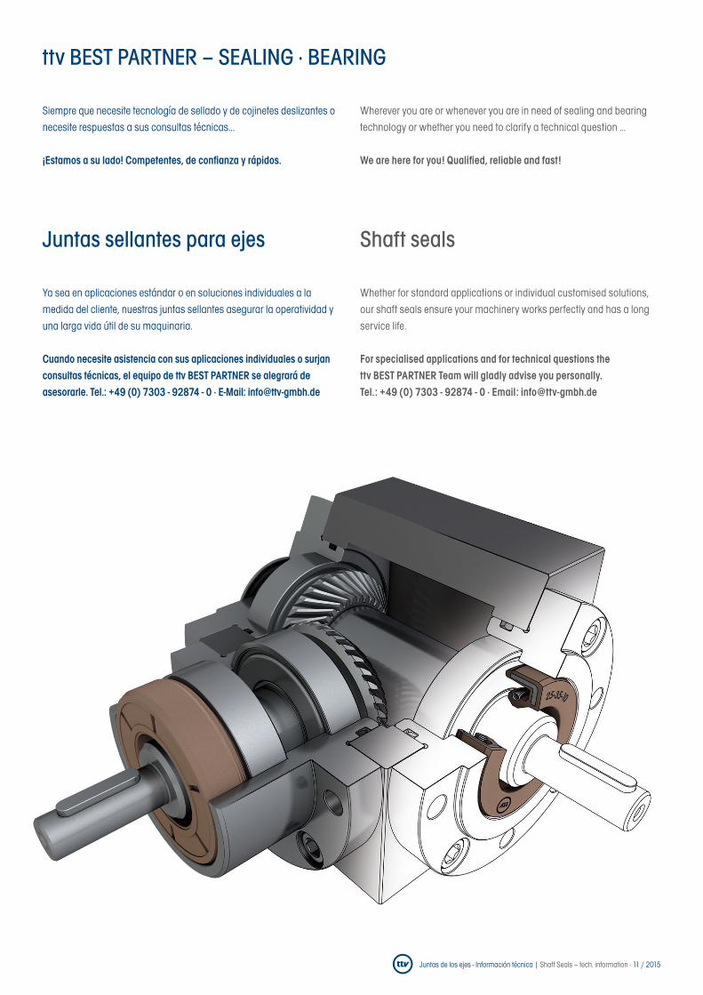
Juntas sellantes para ejes Shaft seals
ttv BEST PARTNER – SEALING · BEARING
Siempre que necesite tecnología de sellado y de cojinetes deslizantes o necesite respuestas a sus consultas técnicas...
¡Estamos a su lado! Competentes, de confianza y rápidos.
Ya sea en aplicaciones estándar o en soluciones individuales a la medida del cliente, nuestras juntas sellantes asegurar la operatividad y una larga vida útil de su maquinaria.
Cuando necesite asistencia con sus aplicaciones individuales o surjan consultas técnicas, el equipo de ttv BEST PARTNER se alegrará de asesorarle. Tel.: +49 (0) 7303 - 92874 - 0 · E-Mail: [email protected]
Wherever you are or whenever you are in need of sealing and bearing technology or whether you need to clarify a technical question …
We are here for you! Qualified, reliable and fast!
Whether for standard applications or individual customised solutions, our shaft seals ensure your machinery works perfectly and has a long service life.
For specialised applications and for technical questions the ttv BEST PARTNER Team will gladly advise you personally. Tel. : +49 (0) 7303 - 92874 - 0 · Email: [email protected]
Juntas de los ejes - Información técnica | Shaft Seals – tech. information · 11 / 2015
Índice | Contents
1. Introducción 4
2. Campos de aplicación posibles 5
3. Principio de funcionamiento 5La superficie exterior 6Estanqueidad 7Condiciones de fricción en la lubricación 9Uso bajo presión 12Anillos de apoyo 13
4. Velocidad de giro y velocidad perimetral 14
5. Temperatura 16
6. El sistema tribológico 17
6.1 Medios 17Medios agresivos 17Requisitos extremos 18Aceites y grasas minerales 18Aceites y grasas sintéticos 18
6.2 Eje 19Tipo de mecanizado 21Superficie del eje 22Materiales de los ejes 22Daños en el eje 23Excentricidad 23Orificio de alojamiento 24
7. Montagehinweise 28Montagehilfen 30
8. Wissenswertes zur Lagerung von Elastomer-Produkten 32
9. Einsatzbereiche der Werkstoffe 32
1. Introduction 4
2. Possible fields of application 5
3. Functional principle 5The outer surface 6Leak-tightness 7Friction states during lubrication 9Use under pressure 12Backup-Rings 13
4. Speeds and circumferential speeds 14
5. Temperature 16
6. The tribological system 17
6.1 Media 17Aggressive media 17Extreme demands 18Mineral-oil-based oils and greases 18Synthetic oils and greases 18
6.2 Shaft 19Processing methods 21Shaft surfaces 22Shaft materials 22Shaft damage 23Eccentricity 23Bore 24
7. Installation instructions 28Installation aids 30
8. Information on storing elastomer products 32
9. Fields of application for the materials 32
Queda reservado el derecho de modificación de la oferta informativa y de cualquier contenido por motivo de nuevas informaciones, resultados de investigación y desarrollo, sin que se indique previamente por
separado. ¡Errores de imprenta y similares sujetos a cambio sin aviso previo! | Information /content is subject to change without notice due to new information, research, and developments. Printing errors and
mistakes reserved!
Juntas de los ejes - Información técnica | Shaft Seals – tech. information · 11 / 20154Ir al índice | to table of contents
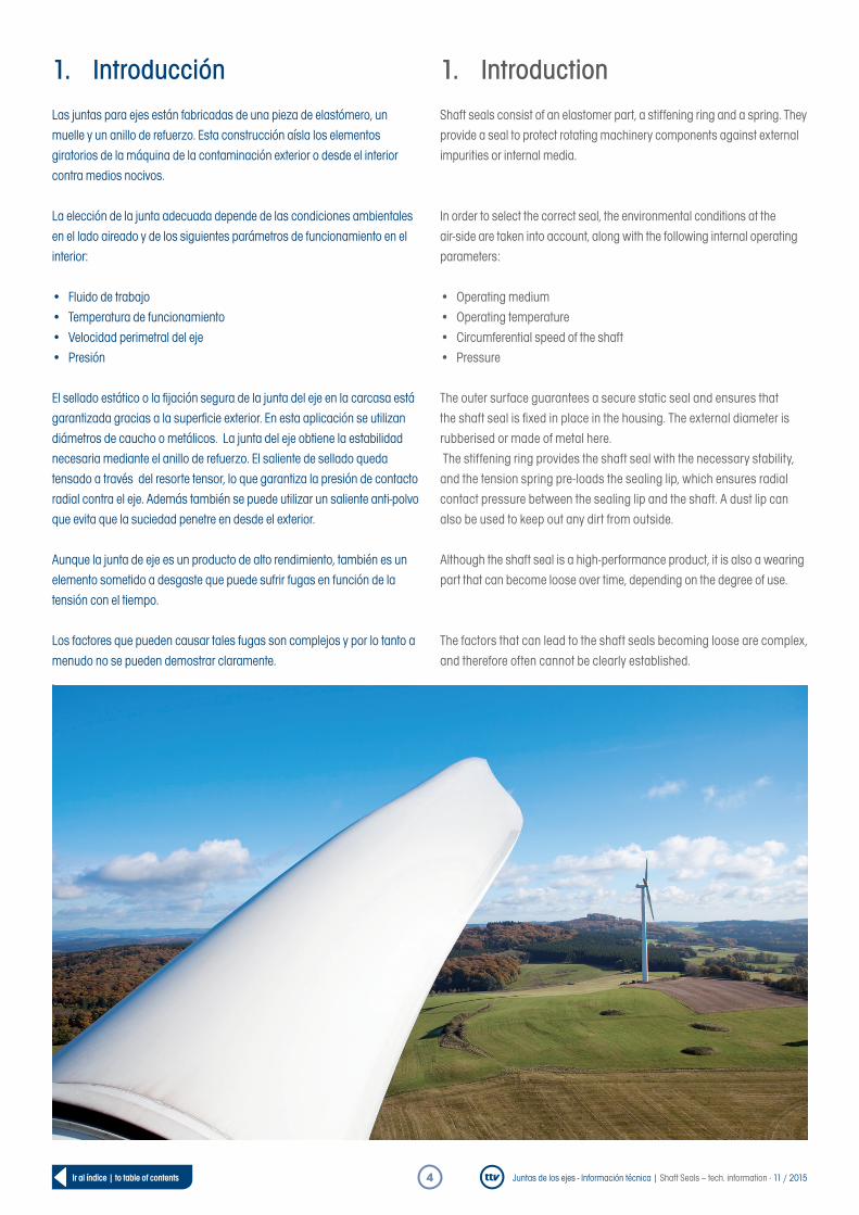
1. IntroducciónLas juntas para ejes están fabricadas de una pieza de elastómero, un muelle y un anillo de refuerzo. Esta construcción aísla los elementos giratorios de la máquina de la contaminación exterior o desde el interior contra medios nocivos.
La elección de la junta adecuada depende de las condiciones ambientales en el lado aireado y de los siguientes parámetros de funcionamiento en el interior:
• Fluido de trabajo• Temperatura de funcionamiento• Velocidad perimetral del eje• Presión
El sellado estático o la fijación segura de la junta del eje en la carcasa está garantizada gracias a la superficie exterior. En esta aplicación se utilizan diámetros de caucho o metálicos. La junta del eje obtiene la estabilidad necesaria mediante el anillo de refuerzo. El saliente de sellado queda tensado a través del resorte tensor, lo que garantiza la presión de contacto radial contra el eje. Además también se puede utilizar un saliente anti-polvo que evita que la suciedad penetre en desde el exterior.
Aunque la junta de eje es un producto de alto rendimiento, también es un elemento sometido a desgaste que puede sufrir fugas en función de la tensión con el tiempo.
Los factores que pueden causar tales fugas son complejos y por lo tanto a menudo no se pueden demostrar claramente..
1. IntroductionShaft seals consist of an elastomer part, a stiffening ring and a spring. They provide a seal to protect rotating machinery components against external impurities or internal media.
In order to select the correct seal, the environmental conditions at the air-side are taken into account, along with the following internal operating parameters:
• Operating medium• Operating temperature• Circumferential speed of the shaft• Pressure
The outer surface guarantees a secure static seal and ensures that the shaft seal is fixed in place in the housing. The external diameter is rubberised or made of metal here. The stiffening ring provides the shaft seal with the necessary stability, and the tension spring pre-loads the sealing lip, which ensures radial contact pressure between the sealing lip and the shaft. A dust lip can also be used to keep out any dirt from outside.
Although the shaft seal is a high-performance product, it is also a wearing part that can become loose over time, depending on the degree of use.
The factors that can lead to the shaft seals becoming loose are complex, and therefore often cannot be clearly established.
Juntas de los ejes - Información técnica | Shaft Seals – tech. information · 11 / 20155Ir al índice | to table of contents
2. Campos de aplicación posiblesLas juntas de sellado para ejes se utilizan en múltiples ramos industriales para sellar elementos rotativos de la maquinaria , tales como bujes, árboles y ejes:
• En la agricultura o la industria de la construcción (en estas máquinas, que están expuestas a una fuerte suciedad, garantizan así intervalos de mantenimiento más largos y una mayor vida útil)
• En tecnologías de accionamientos - sistemas de transmisión, motores eléctricos y motores de combustión
• En bombas• En lavadoras domésticas e industriales (los materiales deben
ser resistentes a la espuma de jabón y resistentes al agua y a las variaciones de temperatura)
• En la construcción naval, la industria de aerogeneración y en fábricas de laminación - Para estas aplicaciones ttv ofrece diseños y perfi les especiales.
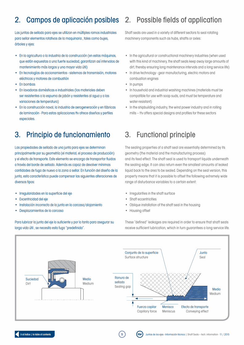
3. Principio de funcionamientoLas propiedades de sellado de una junta para ejes se determinan principalmente por su geometría (el material, el proceso de producción) y el efecto de transporte. Este elemento se encarga de transportar fl uidos a través del borde de sellado. Además es capaz de devolver mínimas cantidades de fuga de nuevo a la zona a sellar. En función del diseño de la junta, esta característica puede compensar las siguientes alteraciones de diversos tipos:
• Irregularidades en la superfi cie del eje• Excentricidad del eje• Instalación incorrecta de la junta en la carcasa/alojamiento• Desplazamientos de la carcasa
Para lubricar la junta del eje lo sufi ciente y por lo tanto para asegurar su larga vida útil , se necesita esta fuga “predefi nida”.
2. Possible fi elds of applicationShaft seals are used in a variety of different sectors to seal rotating machinery components such as hubs, shafts or axles:
• In the agricultural or constructional machinery industries (when used with this kind of machinery, the shaft seals keep away large amounts of dirt, thereby ensuring long maintenance intervals and a long service life)
• In drive technology - gear manufacturing, electric motors and combustion engines
• In pumps• In household and industrial washing machines (materials must be
compatible for use with soap suds, and must be temperature and water-resistant)
• In the shipbuilding industry, the wind power industry and in rolling mills – ttv offers special designs and profi les for these sectors
3. Functional principleThe sealing properties of a shaft seal are essentially determined by its geometry (the material and the manufacturing process)and its feed effect. The shaft seal is used to transport liquids underneath the sealing edge. It can also return even the smallest amounts of leaked liquid back to the area to be sealed. Depending on the seal version, this property means that it is possible to offset the following extremely wide range of disturbance variables to a certain extent:
• Irregularities in the shaft surface• Shaft eccentricities• Oblique installation of the shaft seal in the housing• Housing offset
These “defi ned” leakages are required in order to ensure that shaft seals receive suffi cient lubrication, which in turn guarantees a long service life.
MedioMedium
SuciedadDirt
MeniscoMeniscus
Efecto de transporteConveying effect
Fuerza capilarCapillary force
Ranura de selladoSealing gap
MedioMedium
JuntaSeal
Conjunto de la superfi cieSurface structure

Juntas de los ejes - Información técnica | Shaft Seals – tech. information · 11 / 20156Ir al índice | to table of contents
La superficie exterior
La elección de la superficie exterior correcta depende de las condiciones de operación existentes y de la aplicación en particular. Su tarea principal es asegurar la estanqueidad estática de los orificios del alojamiento. Esto quiere decir que la superficie exterior tiene que evitar la fuga de aceite del alojamiento en todas las condiciones de funcionamiento.
La superficie exterior de la junta del eje actúa además de sistema de guía y proporciona un asiento estable en el orificio. El alojamiento se define como sigue:
• Fuerza de fricción FR = Mayor que todas las fuerzas axiales que actúan sobre el eje Fax (por ejemplo, la fuerza resultante de la diferencia de presión)
• Fuerza de fricción FR = Producto del coeficiente de fricción µ0 y de la fuerza radial norma FN
• Fuerza normal FN = fuerza radial en la superficie exterior FA
• Dependiendo del diseño de la superficie exterior se deben añadir distintos tamaños de margen de inserción al diámetro nominal
• La superficie exterior de la junta del eje debe permitir que biseles adecuados y curvas de fácil instalación
• La superficie exterior de la junta del eje debe compensar las diferentes ranuras derivadas de distintos coeficientes de dilatación
The outer surface
The correct outer surface is selected based on the predominant operating conditions and the specific application.
The primary task of the outer surface is to ensure the static leak-tightness at the housing bore on the housing. This means that the outer surface must, in all possible operating conditions, stop the medium from entering at the point where the shaft seal is positioned in the bore on the housing.
The outer surface of the shaft seal ensures correct guidance and makes sure that the shaft seal is securely fitted in the bore. Secure fit is defined as follows:
• Friction force FR = Larger than all other axial forces acting on the shaft seal Fax (e.g. the force resulting from the pressure difference)
• Friction force FR = Product of the static friction coefficient µ0 and the radial normal force FN
• Normal force FN = Radial force on the outer surface FA
• Different press-fit tolerances to the nominal diameter must be applied, depending on the design of the outer surface
• The outer surface of the shaft seal must feature appropriate chamfers and rounded edges to enable easy installation
• The outer surface of the shaft seal must offset the gap caused by different expansion coefficient
FR > Fax
Fax
FA
FN
FR = FN x µ0

Juntas de los ejes - Información técnica | Shaft Seals – tech. information · 11 / 20157Ir al índice | to table of contents
Estanqueidad
Las juntas para ejes actúan deslizando el borde de sellado sobre la superficie del eje en rotación. Dado que el diámetro interior de la junta de sellado del eje es menor que el diámetro del eje, el borde de sellado se presiona contra la superficie del eje. Esta diferencia de diámetro se conoce como sesgo o fuerza radial.
El muelle de gusano apoya la fuerza radial resultante en la zona de contacto lineal. Esto actúa contra la lenta disminución de la fuerza centrífuga (debido al envejecimiento del material elastomérico), conocido como relajación de la tensión.
El efecto de sellado depende de:
• el diseño de la superficie del eje• la interpretación del muelle de gusano• la geometría del saliente de sellado• las propiedades del material elastomérico• el estado de lubricación
El efecto sellante del borde de sellado elastomérico queda asegurado cuando el eje está parado y también con el eje en rotación.
Sellado estático Debido el sesgo se logra la presión sobre el borde de sellado, apoyado por el muelle de gusano. El efecto de sellado se basa en la presión radial del borde de sellado sobre la superficie del eje pulida y libre de rugosidades (véase la pagina 22). La deformación del borde de sellado elastomérico compensa las bajas rugosidades de la superficie del eje y sella también la ranura. Dependiendo de los parámetros de funcionamiento, el sesgo va disminuyendo durante el funcionamiento. La tensión VS se calcula a partir del componente de elastómero FEL por el componente del muelle FFED.
Leak-tightness
The shaft seals work by sliding the sealing edge onto the rotating shaft surface. As the inner diameter of the shaft seal is smaller than the diameter of the shaft, the sealing edge is pressed onto the shaft surface. This difference in diameter is known as pre-load or radial force.
The cylindrical spiral spring supports the resulting radial force on the linear contact area. This counteracts the gradual decrease in the radial force (due to ageing of the elastomer material), or so-called stress relaxation.
The sealing effect depends on:
• the shaft surface design• the design of the cylindrical spiral spring• the geometry of the sealing lip• the properties of the elastomer material• the lubrication condition
The sealing effect at the elastomer sealing edge is guaranteed both when the shaft is stationary and when it is rotating.
Static leak-tightness The contact pressure of the sealing lip is guaranteed by the pre-load, and the sealing lip is supported by the cylindrical spiral spring. The sealing effect here is based on the sealing lip‘s radial contact pressure with the shaft surface, which is ground such that it is non-spiralling (see page 22). The deformation of the elastomer sealing edge compensates for the low surface roughness of the shaft and seals the gap. The elastomer pre-load decreases during operation, depending on the operating parameters. The pre-load VS therefore comprises the elastomer proportion FEL and the elastomer proportion FFED.
El frente | Front sideLa parte inferior | Bottom side
a
FELFFED
VS
hfβ

Juntas de los ejes - Información técnica | Shaft Seals – tech. information · 11 / 20158Ir al índice | to table of contents
Estanqueidad dinámicaEl eje en rotación da lugar a un efecto hidrodinámico. Esto da como resultado que el saliente sellante flota sobre la película lubricante que se forma el elemento a sellar. Esto evita la destrucción térmica del saliente sellante y su fallo prematuro.
La película de aceite debe permanecer en la zona de contacto para evitar el posible desgaste; por otra parte, las fugas provocadas por la salida del medio lubricante a ser sellado en el lado del aire deberán evitarse.
Poco después de que la nueva junta sellante para eje se utilice por primera vez, en la superficie de la zona de contacto se crea una estructura de superficie axial microscópica. Por el movimiento relativo entre el borde de sellado y el eje se produce una distorsión.
Dependiendo de la distribución de la presión en la zona y la dirección de rotación del eje, la orientación de la estructura de la superficie se ve alterada. Desde el lado abierto hacia el lado del medio a sellar, en la zona de contacto se genera el así denominado flujo de arrastre. Este flujo sólo transporta en la dirección correcta cuando existe una distribución asimétrica de presión dentro del ancho axial de la trayectoria de movimiento. Solo así se logra el efecto de transporte necesario de la junta de sellado.
Por el desplazamiento del muelle de gusano hacia el lado abierto, (la así denominada separación de efecto amortiguador y por los diferentes ángulos de la superficie de contacto (a > β) el labio sellante en relación con la superficie del eje se genera una asimetría en la distribución de la presión.
Si el conjunto de la estructura de superficie está inclinado, el medio en la zona de contacto es transportado no sólo en dirección axial, sino también en la dirección perimetral. En medios reticulados, como aceites lubricantes, también su tensión superficial actúa en la dirección de fuga. Esto se produce por efecto al ser atraídos por la fuerza capilar hacia la ranura, formando el así denominado menisco, una superficie límite curvada por el lado abierto.
El efecto de sellado óptimo en un eje es el resultado del equilibrio entre las fuerzas que causan la fuga y el efecto de bombeo de la estructura de la superficie elastomérica.
Dynamic leak-tightnessA hydrodynamic effect takes place when the shaft is rotating. This effect causes the sealing lip to float on the film of lubricant formed by the medium to be sealed. This prevents the thermal destruction of the sealing lip and stops it from failing prematurely.
The film of lubricant should remain in the contact area in order to prevent any wear from occurring there and also to prevent leakage as a result of the medium to be sealed escaping at the air-side.
Shortly after a new shaft seal has been used for the first time, a microscopic axial surface structure forms in the contact area.This surface structure is distorted due to the relative motion between the sealing edge and the shaft.
The orientation of this distorted surface structure changes depending on the contact pressure distribution in the contact area and the rotation direction of the shaft. A so-called drag flow from the air-side to the medium-side of the contact area is produced. This drag flow only provides a feed in the correct direction when there is asymmetrical contact pressure distribution of the axial track width. This is the only way in which the required feed effect of the shaft seal is achieved.
Asymmetrical contact pressure distribution arises as a result of the cylindrical spiral spring shifting to the air-side (the so-called spring-distance) and the different contact surface angles (a > β) between the sealing lip and the shaft surface.
If the surface structure is oblique, the medium is transferred inside the contact area, and not just in the axial direction but in the circumferential direction as well. For a moistening medium such as lubricating oil, for example, the surface tension of this medium also takes effect in the direction of the leak. This takes place as a result of the medium being drawn into the sealing gap by means of capillary force, where it forms the so-called meniscus, a curved boundary surface on the air-side.
The optimal sealing effect for a shaft seal comes about as a result of equilibrium between the forces that cause the leak and the pumping effect of the elastomer surface structure.
Lado del material a sellarMedium-side
Distribución de la presión Contact pressure distribution
VS
Zona de contacto Contact area
Lado abiertoAir-side
MeniscoMeniscus
Efecto de transporteConveying effect
Fuerza capilarCapillary force
Ranura de selladoSealing gap
MedioMedium
JuntaSeal
Conjunto de la superficieSurface structure

Juntas de los ejes - Información técnica | Shaft Seals – tech. information · 11 / 20159Ir al índice | to table of contents
Condiciones de fricción en la lubricación
Durante la interacción entre eje, junta sellante del eje y el lubricante actúan tres factores, siendo el lubricante el que hace una contribución más significativa a la vida y la fiabilidad de todo el sistema.
Por medio de las fuerzas capilares existente, la sustancia o medio lubricante se distribuye a una velocidad baja por la zona de contacto. Dado que esta zona está expuesta a estrés térmico, el transporte del fluido por efecto de las fuerzas capilares es indispensable.
Con mayor frecuencia se produce una fricción mixta entre el saliente sellante y el eje, desempeñando los materiales de las dos superficies de contacto un papel crucial.
Si aumenta la velocidad de rotación, variará con ello el estado de fricción, yendo de un estado de fricción sólida, pasando por fricción mixta hasta llegar a una fricción hidrodinámica.En estas condiciones, el saliente sellante flota sobre la película de aceite, creada por el medio a sellar.
La película lubricante hidrodinámica resultante evita la fricción y el desgaste prematuro y con ello la destrucción térmica del saliente de sellado elastomérico.
Un suministro continuo y suficiente de lubricante al saliente sellante asegura una larga vida útil del equipo.
La fricción y la pérdida de la misma dependen fundamentalmente delos siguientes parámetros:
• El material de la junta sellante utilizada• El tipo de superficie del eje• La fuerza radial/centrípeta• La velocidad perimetral• La presión aplicada• Las condiciones de lubricación• La temperatura
Friction states during lubrication
Three parties are involved in the interaction between shaft, shaft seal and lubricant, whereby the lubricant makes a crucial contribution to the service life and functional reliability of the entire system.
As a result of the prevailing capillary forces, the medium is distributed throughout the contact area even at low speeds. As the contact area is subjected to a heavy thermal load, capillary-force based fluid feed is essential.
There is very often mixed friction between the sealing lip and the shaft, whereby the materials of the two contact surfaces are of crucial importance.
If the speed increases, the friction state changes from solid state friction through mixed friction to hydrodynamic fluid friction. During this process, the sealing lip floats on the film of lubricant formed by the medium to be sealed.
This hydrostatic film of lubricant prevents friction, thereby preventing premature wearing and thermal destruction of the elastomer sealing edge.
A constant and sufficient supply of lubricant to the sealing edge ensures a long service life.
Friction and friction loss depend crucially on the following parameters:
• Shaft seal material• Shaft seal surface type• Radial force• Circumferential speed• Pressurisation• Lubrication condition• Temperature
Estados de fricción en la zona de contacto | Friction states in the contact zone
Fricción de cuerpos sólidos | Solid state friction
Fricción mixta | Mixed friction
Fricción de fluidos | Hydrodynamic fluid friction
Juntas de los ejes - Información técnica | Shaft Seals – tech. information · 11 / 201510Ir al índice | to table of contents
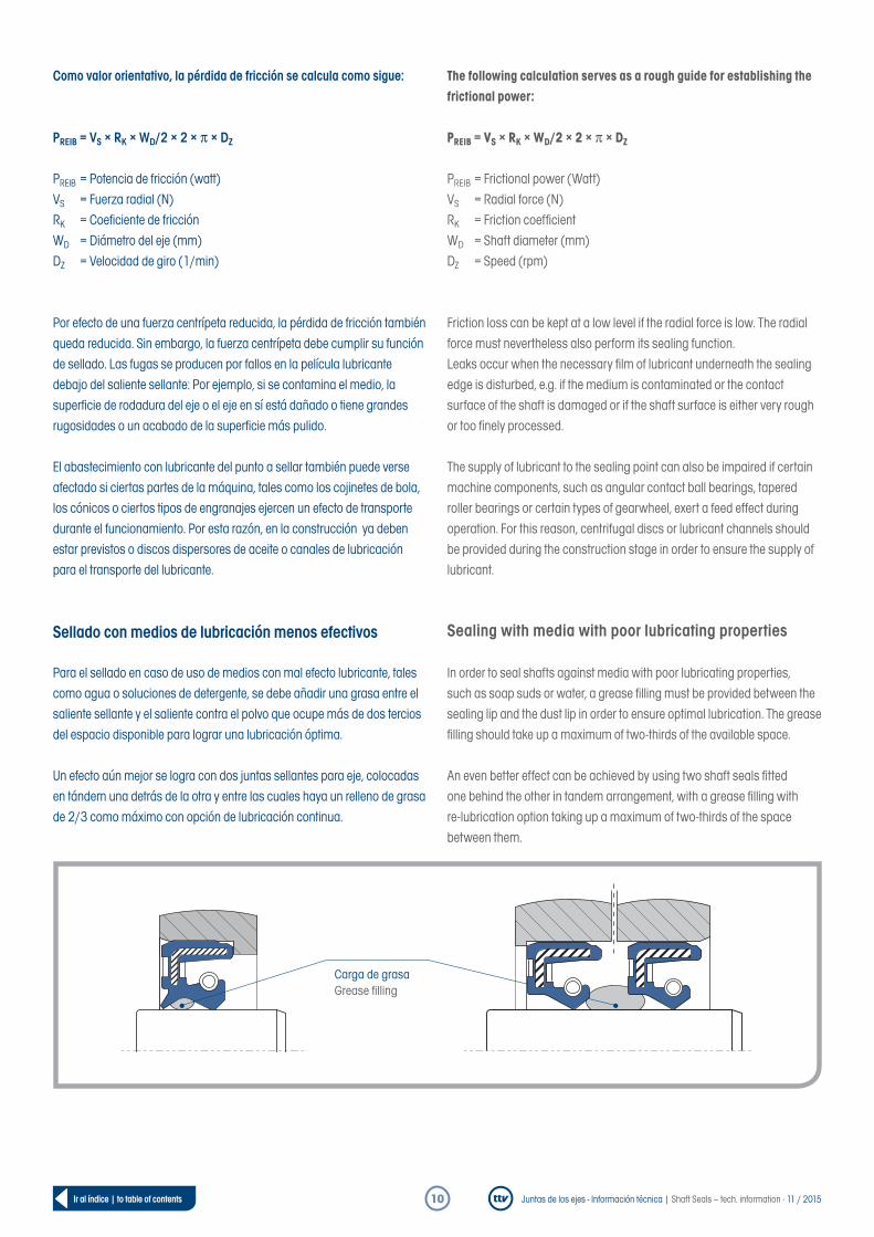
Como valor orientativo, la pérdida de fricción se calcula como sigue:
PREIB = VS × RK × WD/2 × 2 × π × DZ
PREIB = Potencia de fricción (watt)VS = Fuerza radial (N)RK = Coefi ciente de fricciónWD = Diámetro del eje (mm)DZ = Velocidad de giro (1/min)
Por efecto de una fuerza centrípeta reducida, la pérdida de fricción también queda reducida. Sin embargo, la fuerza centrípeta debe cumplir su función de sellado. Las fugas se producen por fallos en la película lubricante debajo del saliente sellante: Por ejemplo, si se contamina el medio, la superfi cie de rodadura del eje o el eje en sí está dañado o tiene grandes rugosidades o un acabado de la superfi cie más pulido.
El abastecimiento con lubricante del punto a sellar también puede verse afectado si ciertas partes de la máquina, tales como los cojinetes de bola, los cónicos o ciertos tipos de engranajes ejercen un efecto de transporte durante el funcionamiento. Por esta razón, en la construcción ya deben estar previstos o discos dispersores de aceite o canales de lubricación para el transporte del lubricante.
Sellado con medios de lubricación menos efectivos
Para el sellado en caso de uso de medios con mal efecto lubricante, tales como agua o soluciones de detergente, se debe añadir una grasa entre el saliente sellante y el saliente contra el polvo que ocupe más de dos tercios del espacio disponible para lograr una lubricación óptima.
Un efecto aún mejor se logra con dos juntas sellantes para eje, colocadas en tándem una detrás de la otra y entre las cuales haya un relleno de grasa de 2/3 como máximo con opción de lubricación continua.
The following calculation serves as a rough guide for establishing the frictional power:
PREIB = VS × RK × WD/2 × 2 × π × DZ
PREIB = Frictional power (Watt)VS = Radial force (N)RK = Friction coeffi cientWD = Shaft diameter (mm)DZ = Speed (rpm)
Friction loss can be kept at a low level if the radial force is low. The radial force must nevertheless also perform its sealing function.Leaks occur when the necessary fi lm of lubricant underneath the sealing edge is disturbed, e.g. if the medium is contaminated or the contact surface of the shaft is damaged or if the shaft surface is either very rough or too fi nely processed.
The supply of lubricant to the sealing point can also be impaired if certain machine components, such as angular contact ball bearings, tapered roller bearings or certain types of gearwheel, exert a feed effect during operation. For this reason, centrifugal discs or lubricant channels should be provided during the construction stage in order to ensure the supply of lubricant.
Sealing with media with poor lubricating properties
In order to seal shafts against media with poor lubricating properties, such as soap suds or water, a grease fi lling must be provided between the sealing lip and the dust lip in order to ensure optimal lubrication. The grease fi lling should take up a maximum of two-thirds of the available space.
An even better effect can be achieved by using two shaft seals fi tted one behind the other in tandem arrangement, with a grease fi lling with re-lubrication option taking up a maximum of two-thirds of the space between them.
Carga de grasaGrease fi lling

Juntas de los ejes - Información técnica | Shaft Seals – tech. information · 11 / 201511Ir al índice | to table of contents
Lubricación insuficientePara evitar que ka disipación del calor no funcione y con ello se dé un desgaste prematuro del saliente sellante, se debe evitar en cualquier caso que el eje gire sin lubricación de la junta. Por esta razón es recomendable engrasar ligeramente el borde sellante de la junta durante la instalación inicial. Además de la sustancia lubricante, el medio sellante debe poder disipar de forma continua cualquier calor derivado de la fricción.
Si se desea una lubricación insuficiente es posible usar determinados diseños y materiales, como p. ej. juntas/retenes sellantes con saliente de PTFE.
Lubricación con grasaEn comparación con la lubricación de aceite, la disipación de calor de fricción usando grasa es mucho menor. Por lo tanto, sólo se deben utilizar en los ejes de rotación lenta. La velocidad perimetral no debe exceder la mitad del valor admisible para la lubricación con aceite. (consulte la tabla de velocidades de giro, pág. 15)
Con el fin de sellar de manera óptima ejes de giro lento debe usarse grasa rellenando casi por completo entre la junta del eje y el cojinete. También es posible usar una junta eje con saliente de PTFE cuando no hay grasa adecuada que se pueda utilizar.
Helicoidales – Apoyos contra desvíosSi se quiere aumentar la fiabilidad y la eficiencia de transporte de una junta de eje es posible usar medios auxiliares de sellado hidrodinámicos, denominados helicoidales. Estos disponen de estructuras de retorno colocadas en ángulo oblicuo en relación al borde sellante.
Dependiendo de la dirección de giro del eje es posible utilizar juntas sellantes con deriva hacia derecha/izquierda o deriva alterna. Si se perturba el efecto normal de transporte, estos componentes ayudan a prevenir vertidos hacia el lado abierto y que el lubricante vuelva a la zona de contacto del saliente de sellado.
Las juntas helicoidales para ejes cuentan por tanto con un doble mecanismo de sellado. En realidad tienen el mismo principio de funcionamiento que una junta eje roscado. Una junta para eje con deriva sencilla proporciona un nivel de transporte mucho mayor que una junta de diseño estándar. Especialmente bajo condiciones de funcionamiento difíciles, tales como la concentricidad, coaxialidad entre eje y orificio de alojamiento y daños menores en la superficie del eje, los sistemas hidrodinámicos de sellado mejoran la seguridad funcional de la junta.
Insufficient lubricationIn order to prevent premature wear of the sealing edge due to non-functional heat removal, it must be ensured that the shaft does not rotate around the shaft seal without lubrication. For this reason, it is recommended that the sealing edge of the shaft seal be lightly greased during assembly. Beside lubrication, the medium to be sealed must also continuously remove any frictional heat that arises.
If insufficient lubrication is required, certain designs and materials, such as shaft seals with PTFE sealing lips, can be used.
Grease lubricationThe level of frictional heat removal is much lower with pure grease lubrication compared to oil lubrication. Therefore, grease lubrication should only be used with slowly rotating shafts. The circumferential speed should be a maximum of half the permitted value for oil lubrication(see speed table on page 15)
In order to seal slowly rotating shafts as effectively as possible, the area between the sealing ring and the bearing should be almost completely filled with grease. A shaft seal with a PTFE sealing lip is another option if no appropriate lubricating grease can be used.
Helix spiral aidsIf the functional reliability and feed effect of a shaft seal need to be increased, additional hydrodynamic sealing aids are available in the form of so-called helices These have enhanced flow-back structures that run to the sealing edge at a slanted angle.
Shaft seals with a right or left-hand spiral or with an alternating spiral are used, depending on the shaft‘s rotation direction. If the normalfeed effect is impaired, the spiral aids are designed to ensure that the medium flowing towards the air-side does not flow out as a leakage, but instead is fed back into the contact area of the sealing edge.
In this way, helical shaft seals offer twice the amount of protection against leaks. They work on the principle of a simple threaded shaft seal. A shaft seal with a single spiral has a considerably higher feed effect than the same shaft seal in standard design. Hydrodynamic sealing aids make particular improvements to the functional reliability of the shaft seal under difficult operating conditions such as concentricity, coaxiality between the shaft and the bore, and small amounts of damage on the shaft surface.
W R L
Helicoidales | Helix
Juntas de los ejes - Información técnica | Shaft Seals – tech. information · 11 / 201512Ir al índice | to table of contents
Uso bajo presión
Uso bajo condiciones operativas con presiónEl factor decisivo para la elección de juntas de eje adecuadas es la carga combinada que resulta de la presión “P” y la velocidad perimetral “V”.
Las juntas sellantes del eje diseñadas para presiones más alta ejercen una mayor presión de contacto contra el eje. Esto aporta un mayor efecto de sellado porque hay un efecto de auto-refuerzo de la fuerza radial al aumentar esta sobre el área efectiva en función de la presión.
La capacidad de sellado de la junta para eje se adapta a la diferencia de presión existente bajo ciertas circunstancias. Esto también produce un aumento de la fricción en el saliente sellante y una tensión térmica mayor. Esto puede causar un endurecimiento y desgaste prematuro de la junta. Si la presión es demasiado alta, puede dar lugar a que la junta se doble por el lado abierto (lado expuesto al aire). Con ello la junta giraría sobre su propia “espalda”. La mayor carga térmica en el borde de sellado debe tenerse en cuenta al seleccionar el material elastómero en todas las circunstancias.
Por esta razón, los valores orientativos de velocidad de giro y de velocidad perimetral de la página 15 no se aplican a juntas sellantes para ejes sometidas a alta presión.
La presión de las juntas sellantes para ejes también afectará al saliente sellante: con ello disminuye su capacidad para compensar el desvío del centrado radial del eje y la tolerancia a la coaxialidad entre el eje y su alojamiento.
Para prevenir la salida por efecto de la presión del orificio de alojamiento, las juntas de eje a presión deben ser aseguradas axialmente por el lado más alejado de la presión usando un anillo espaciador, un resalte de la carcasa o un anillo de retención.
Use under pressure
Use when operating with pressurisationThe combined strain that arises from the pressure “P” and the circumferential speed “V” is of crucial importance in selecting the appropriate shaft seal.
Shaft seals designed to be used at higher pressures have higher levels of contact pressure between the sealing lip and the shaft. This causes increased sealing effect, as the radial force experiences a self-strengthening effect whereby it increases on the effective surface in accordance with the pressure.
The sealing capacity of the shaft seal adapts to a certain extent to the prevailing pressure difference. However, this also leads to increased frictional power at the sealing edge and increased thermal load. This can cause the sealing ring to harden and can bring about its premature wear. If the pressure is too high, this can cause the sealing lip to collapse downwards to the air-side. The shaft seal then runs on its “back”. The increased thermal load on the sealing edge must be taken into account at all times when selecting the elastomer material.
The reference values listed on page 15 for circumferential speed and speed therefore do not apply to pressurised shaft seals.
The pressurisation of the shaft seal also has an impact on the sealing lip, in that it reduces the sealing lip‘s ability to offset the shaft‘s radial run-out deviation and the coaxiality tolerance between the shaft and the mounting bore.
In order to prevent expulsion of the shaft seal from out of the mounting bore, a spacer ring, housing shoulder or circlip must be used to secure the pressurised shaft seals axially on the side facing away from the pressure.
Juntas de los ejes - Información técnica | Shaft Seals – tech. information · 11 / 201513Ir al índice | to table of contents
Presión en diseños estándarDie Auslegung eines Standard-Wellendichtrings ist für den Einsatz bei geringen Drücken. Sie eignen sich zum Abdichten von Räumen mit geringen Druckdifferenzen von maximal 0,5 bar in Abhängigkeit von der Drehzahl gegen Fette, Flüssigkeiten und sogar Luft.
Nachfolgende Tabelle listet die Grenzwerte für den Druck in Abhängigkeit von Drehzahl und Umfangsgeschwindigkeit auf.
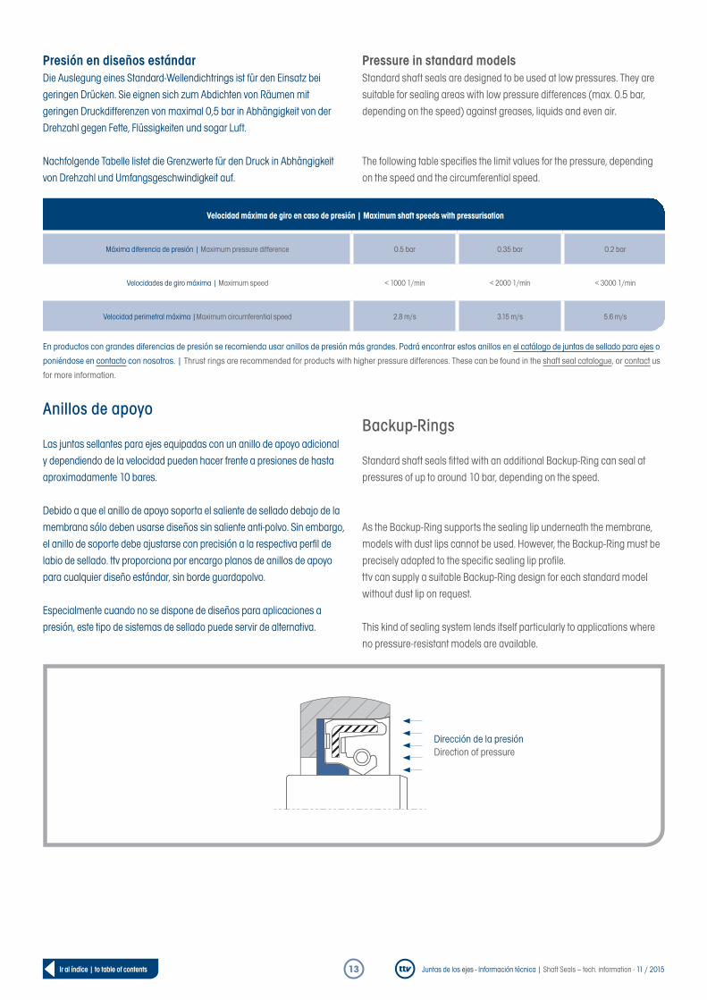
Anillos de apoyo
Las juntas sellantes para ejes equipadas con un anillo de apoyo adicional y dependiendo de la velocidad pueden hacer frente a presiones de hasta aproximadamente 10 bares.
Debido a que el anillo de apoyo soporta el saliente de sellado debajo de la membrana sólo deben usarse diseños sin saliente anti-polvo. Sin embargo, el anillo de soporte debe ajustarse con precisión a la respectiva perfi l de labio de sellado. ttv proporciona por encargo planos de anillos de apoyo para cualquier diseño estándar, sin borde guardapolvo.
Especialmente cuando no se dispone de diseños para aplicaciones a presión, este tipo de sistemas de sellado puede servir de alternativa.
En productos con grandes diferencias de presión se recomienda usar anillos de presión más grandes. Podrá encontrar estos anillos en el catálogo de juntas de sellado para ejes o
poniéndose en contacto con nosotros. | Thrust rings are recommended for products with higher pressure differences. These can be found in the shaft seal catalogue, or contact us
for more information.
Pressure in standard modelsStandard shaft seals are designed to be used at low pressures. They are suitable for sealing areas with low pressure differences (max. 0.5 bar, depending on the speed) against greases, liquids and even air.
The following table specifi es the limit values for the pressure, depending on the speed and the circumferential speed.
Backup-Rings
Standard shaft seals fi tted with an additional Backup-Ring can seal at pressures of up to around 10 bar, depending on the speed.
As the Backup-Ring supports the sealing lip underneath the membrane, models with dust lips cannot be used. However, the Backup-Ring must be precisely adapted to the specifi c sealing lip profi le.ttv can supply a suitable Backup-Ring design for each standard model without dust lip on request.
This kind of sealing system lends itself particularly to applications where no pressure-resistant models are available.
Velocidad máxima de giro en caso de presión | Maximum shaft speeds with pressurisation
Máxima diferencia de presión | Maximum pressure difference 0.5 bar 0.35 bar 0.2 bar
Velocidades de giro máxima | Maximum speed < 1000 1/min < 2000 1/min < 3000 1/min
Velocidad perimetral máxima |Maximum circumferential speed 2.8 m/s 3.15 m/s 5.6 m/s
Dirección de la presiónDirection of pressure

Juntas de los ejes - Información técnica | Shaft Seals – tech. information · 11 / 201514Ir al índice | to table of contents
4. Velocidad de giro y velocidad perimetral
La velocidad perimetral V del eje se calcula a partir de la velocidad de giro “n” y del diámetro del eje “d”:
Cálculo de la velocidad perimetral
V =
V = Velocidad (m/s)n = Velocidad de giro (l/min)d = Diámetro del eje (mm)
Las temperaturas extremas en el borde de sellado que perjudiquen el funcionamiento pueden conducir al endurecimiento del elastómero o acumulación de carbón. Para evitar esto, la velocidad perimetral debe limitarse.
En la tabla de la página siguiente se muestran los valores orientativos para la selección del material en función de la velocidad perimetral máxima. Los valores orientativos que aportamos son valores fruto de nuestra experiencia y conformes con DIN 3760a.
Las características específicas del fabricante de juntas sellantes para ejes, como por ejemplo la fuerza radial y la geometría del saliente sellante, no se toman en cuenta.
Los valores enumerados son, sin embargo, válidos cuando no hay presión, con suficiente lubricación y una excelente disipación de calor en el punto de sellado.
En caso de lubricación exclusivamente con grasa se aplicarán valores a la mitad. Del mismo modo, los valores aplicables a superficies de baja calidad en la zona de funcionamiento, a presión o en caso de grandes descentramientos deberán reducirse.
La sección transversal del eje aumenta con el cuadrado del diámetro. Por tanto, los ejes con diámetro mayor toleran velocidades perimetrales más altas que los ejes con menor diámetro. Esto además da lugar a una mejor disipación del calor.
4. Speeds and circumferential speeds
The shaft‘s circumferential speed V is generated from the speed n and the shaft diameter d, using the following formula:
Calculating the circumferential speed
V =
V = circumferential speed (m/s)n = speed (rpm)d = shaft diameter (mm)
Excessive temperatures at the sealing edge that are dangerous to operation can lead to hardening of the elastomer or to oil carbon build-ups. The circumferential speed must be limited in order to prevent this from occurring.
The table on the next page gives the reference values to be used when selecting the material, depending on the maximum permissible circumferential speed. The specified reference values are empirical values in accordance with DIN 3760.
Manufacturer-specific shaft seal properties, such as the radial force or geometry of the sealing lip, are not taken into account here.
The listed reference values are, however, only valid for unpressurised operation with sufficient lubrication and good heat removal.
The reference values apply at 50% if using pure grease lubrication or reduced lubrication. The reference values must also be reduced in the event of poor surface quality in the running area, pressurisation or high radial run-out deviation.
The cross-section of the shaft increases in line with the square of the diameter. Therefore, higher circumferential speeds are permitted with shafts with larger diameters than with shafts with smaller diameters. This enables better heat removal.
60 × 1000 60 × 1000d×π×n d×π×n

Juntas de los ejes - Información técnica | Shaft Seals – tech. information · 11 / 201515Ir al índice | to table of contents
Número de revoluciones del eje | Shaft Seal
Diámetro del eje | Shaft diameter
Velocidad del eje en rev. / min | Shaft speed in rpm
Velo
cida
d pe
rimet
ral
| Ci
rcum
fere
ntia
l spe
ed
m /s
35
30
25
20
15
10
5
0
0 20 40 60 80 100 120 140 160 180
MVQ & FPM
ACM
NBR
3000
0
1500
0
1000
0
9000
8000
7000
6000
5000
4500
4000
3500
3000
2500
2000
1500
1000
500
mm

Juntas de los ejes - Información técnica | Shaft Seals – tech. information · 11 / 201516Ir al índice | to table of contents
5. TemperaturaLa rotación del eje genera fricción en el borde de sellado. Por lo tanto, la temperatura real en este punto es mayor que en el baño de aceite. Esta diferencia de temperatura debe respetarse escrupulosamente.
tD = tÖl + tÜ
Decisivo para esto son:• El material de la junta sellante utilizada• El acabado/estructura de la superficie del eje• El nivel de aceite y / o el estado de la lubricación• La velocidad perimetral• La carga por presión• La disipación de calor
El exceso de temperatura en el borde de sellado aumenta con el aumento de velocidad perimetral. En función de la velocidad perimetral, el exceso de temperatura puede llegar hasta 40 °C. Exceder la temperatura de funcionamiento máxima admisible en los diversos materiales de elastómero conduce a un desgaste prematuro y el endurecimiento excesivo del material. En la página 32 se muestran las temperaturas de funcionamiento de los materiales elastoméricos admisibles de los productos ttv. La indicación sobre la temperatura máxima especificada se refiere a la temperatura en el borde de sellado.
5. TemperatureThe rotation of the shaft produces friction at the sealing edge, meaning that the actual temperature at the sealing edge is higher than the temperature in the oil bath. This temperature difference must be taken into account without fail.
tD = tÖl + tÜ
Crucial factors affecting this are:• Shaft seal material• Shaft surface properties• Oil level and/or lubrication condition• Circumferential speed• Pressure load• Heat removal
The overtemperature at the sealing edge increases as the circumferential speed increases. Depending on the circumferential speed, the overtemperature can reach up to +40°C. If the maximum permissible operating temperatures for the various elastomer materials are exceeded, this can lead to premature hardening and heavy material wear.The permissible operating temperatures for the elastomer materials used in ttv products are shown on the table on page 32. The specified maximum temperature refers to the temperature at the sealing edge.
Condiciones de referencia | Reference conditions
Velocidad de deslizamiento
Sliding speed 12 m/s
Aceite | Oil 10/50
Presión de aceite | Oil pressure ninguna | none
Temperatura del aceite
Oil temperature 110 °C
Temperatura del aire
Air temperature 50 °C
Temperatura ambiente
Ambient temperature 50 °C
Material circundante
Surrounding material de hierro | iron
Material de sellado
Sealing material NBR - HNBR - FPM
110 °C
108 °C
120 °C
115 °C
130 °C
140 °C
150 °C
Aceite | Oil 110 °CAire | Air 25 °C
Juntas de los ejes - Información técnica | Shaft Seals – tech. information · 11 / 201517Ir al índice | to table of contents
6. El sistema tribológico6.1 MediosLa vida útil de la junta depende en gran medida de la estabilidad química de la junta del eje en contacto con el medio utilizado. La selección de la junta del eje adecuada y en particular del material adecuado depende de los siguientes parámetros:
• La velocidad perimetral del eje• La presión de carga y el aumento de la temperatura por la fricción• El medio a sellar y la temperatura
La química del medio utilizado puede ablandar el material hinchándolo o reducir su volumen debido al endurecimiento y por lo tanto, favorecido por las altas temperaturas, dar lugar a un desgaste prematuro. La lista de compatibilidad de los materiales le muestra el comportamiento de los grupos de materiales individuales aplicados a una variedad de medios.
Los ensayos preliminares le aportarán mayor seguridad, por ejemplo, cuando varios parámetros de aplicaciones extremas son relevantes, tales como la presión, la temperatura o la velocidad periférica o si se utilizan los medios nuevos. También una prueba de laboratorio o una consulta específica al fabricante del medio puede servir para garantizar la seguridad. Un ensayo en condiciones de fabricación en serie es la mejor opción para saber si la junta es adecuada para el uso previsto.
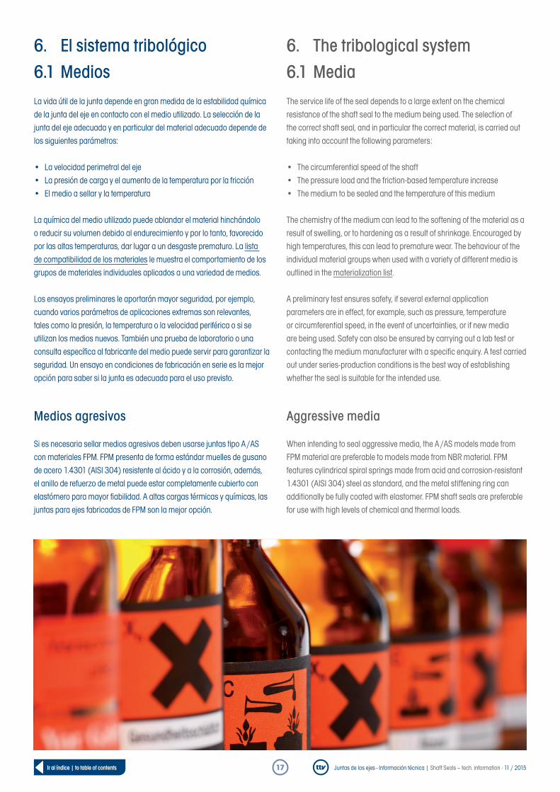
Medios agresivos Si es necesaria sellar medios agresivos deben usarse juntas tipo A /AS con materiales FPM. FPM presenta de forma estándar muelles de gusano de acero 1.4301 (AISI 304) resistente al ácido y a la corrosión, además, el anillo de refuerzo de metal puede estar completamente cubierto con elastómero para mayor fiabilidad. A altas cargas térmicas y químicas, las juntas para ejes fabricadas de FPM son la mejor opción.
6. The tribological system6.1 MediaThe service life of the seal depends to a large extent on the chemical resistance of the shaft seal to the medium being used. The selection of the correct shaft seal, and in particular the correct material, is carried out taking into account the following parameters:
• The circumferential speed of the shaft• The pressure load and the friction-based temperature increase• The medium to be sealed and the temperature of this medium
The chemistry of the medium can lead to the softening of the material as a result of swelling, or to hardening as a result of shrinkage. Encouraged by high temperatures, this can lead to premature wear. The behaviour of the individual material groups when used with a variety of different media is outlined in the materialization list.
A preliminary test ensures safety, if several external application parameters are in effect, for example, such as pressure, temperature or circumferential speed, in the event of uncertainties, or if new media are being used. Safety can also be ensured by carrying out a lab test or contacting the medium manufacturer with a specific enquiry. A test carried out under series-production conditions is the best way of establishing whether the seal is suitable for the intended use.
Aggressive media When intending to seal aggressive media, the A /AS models made from FPM material are preferable to models made from NBR material. FPM features cylindrical spiral springs made from acid and corrosion-resistant 1.4301 (AISI 304) steel as standard, and the metal stiffening ring can additionally be fully coated with elastomer. FPM shaft seals are preferable for use with high levels of chemical and thermal loads.
Juntas de los ejes - Información técnica | Shaft Seals – tech. information · 11 / 201518Ir al índice | to table of contents
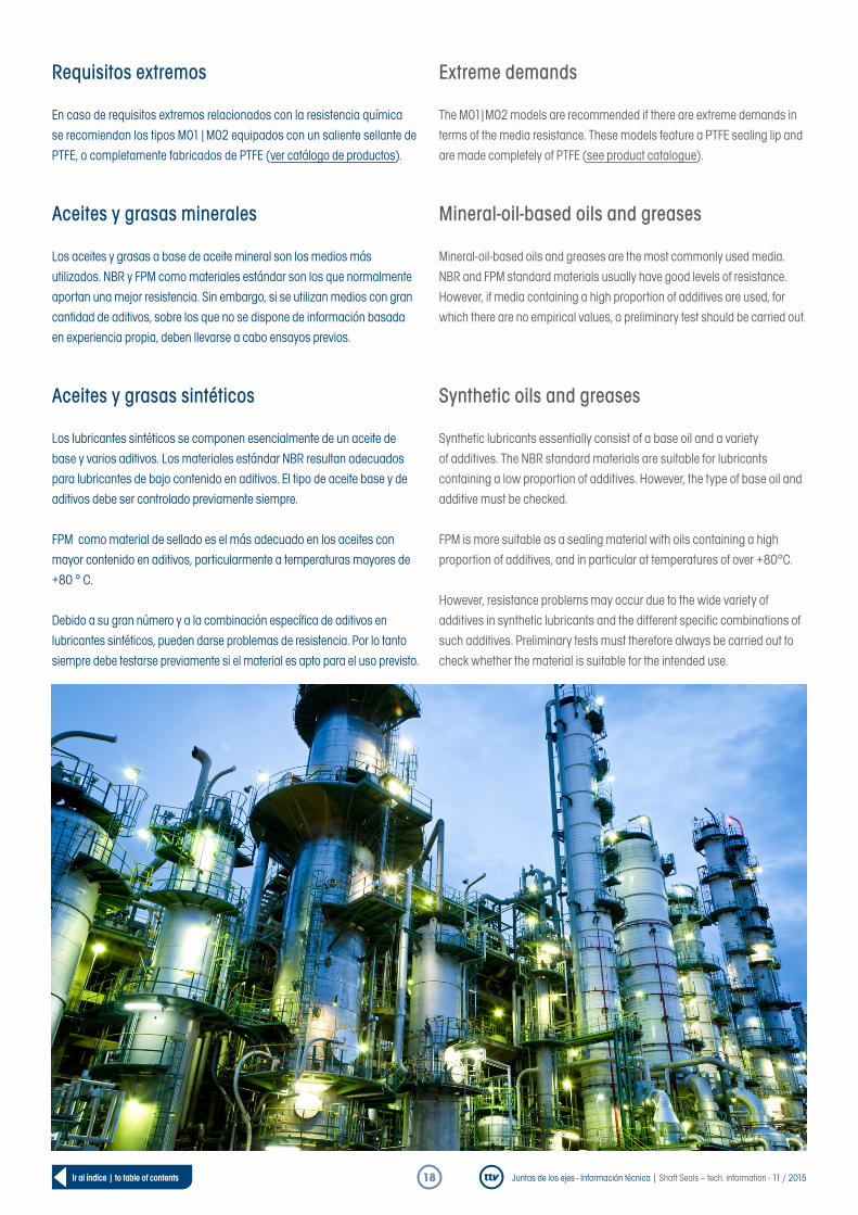
Requisitos extremos En caso de requisitos extremos relacionados con la resistencia química se recomiendan los tipos M01|M02 equipados con un saliente sellante de PTFE, o completamente fabricados de PTFE (ver catálogo de productos).
Aceites y grasas minerales Los aceites y grasas a base de aceite mineral son los medios más utilizados. NBR y FPM como materiales estándar son los que normalmente aportan una mejor resistencia. Sin embargo, si se utilizan medios con gran cantidad de aditivos, sobre los que no se dispone de información basada en experiencia propia, deben llevarse a cabo ensayos previos.
Aceites y grasas sintéticos Los lubricantes sintéticos se componen esencialmente de un aceite de base y varios aditivos. Los materiales estándar NBR resultan adecuados para lubricantes de bajo contenido en aditivos. El tipo de aceite base y de aditivos debe ser controlado previamente siempre.
FPM como material de sellado es el más adecuado en los aceites con mayor contenido en aditivos, particularmente a temperaturas mayores de +80 ° C.
Debido a su gran número y a la combinación específica de aditivos en lubricantes sintéticos, pueden darse problemas de resistencia. Por lo tanto siempre debe testarse previamente si el material es apto para el uso previsto.
Extreme demands The M01|M02 models are recommended if there are extreme demands in terms of the media resistance. These models feature a PTFE sealing lip and are made completely of PTFE (see product catalogue).
Mineral-oil-based oils and greases Mineral-oil-based oils and greases are the most commonly used media. NBR and FPM standard materials usually have good levels of resistance. However, if media containing a high proportion of additives are used, for which there are no empirical values, a preliminary test should be carried out.
Synthetic oils and greases Synthetic lubricants essentially consist of a base oil and a variety of additives. The NBR standard materials are suitable for lubricants containing a low proportion of additives. However, the type of base oil and additive must be checked.
FPM is more suitable as a sealing material with oils containing a high proportion of additives, and in particular at temperatures of over +80°C.
However, resistance problems may occur due to the wide variety of additives in synthetic lubricants and the different specific combinations of such additives. Preliminary tests must therefore always be carried out to check whether the material is suitable for the intended use.
Juntas de los ejes - Información técnica | Shaft Seals – tech. information · 11 / 201519Ir al índice | to table of contents
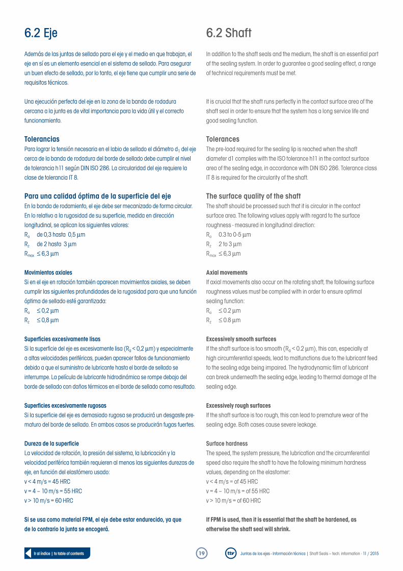
6.2 EjeAdemás de las juntas de sellado para el eje y el medio en que trabajan, el eje en sí es un elemento esencial en el sistema de sellado. Para asegurar un buen efecto de sellado, por lo tanto, el eje tiene que cumplir una serie de requisitos técnicos.
Una ejecución perfecta del eje en la zona de la banda de rodadura cercana a la junta es de vital importancia para la vida útil y el correcto funcionamiento.
ToleranciasPara lograr la tensión necesaria en el labio de sellado el diámetro d1 del eje cerca de la banda de rodadura del borde de sellado debe cumplir el nivel de tolerancia h11 según DIN ISO 286. La circularidad del eje requiere la clase de tolerancia IT 8.
Para una calidad óptima de la superficie del ejeEn la banda de rodamiento, el eje debe ser mecanizado de forma circular.En lo relativo a la rugosidad de su superficie, medida en dirección longitudinal, se aplican los siguientes valores:Ra de 0,3 hasta 0,5 µmRz de 2 hasta 3 µmRmax ≤ 6,3 µm
Movimientos axialesSi en el eje en rotación también aparecen movimientos axiales, se deben cumplir las siguientes profundidades de la rugosidad para que una función óptima de sellado esté garantizada:Ra ≤ 0,2 µmRz ≤ 0,8 µm
Superficies excesivamente lisasSi la superficie del eje es excesivamente lisa (Ra < 0,2 µm) y especialmente a altas velocidades periféricas, pueden aparecer fallos de funcionamiento debido a que el suministro de lubricante hasta el borde de sellado se interrumpe. La película de lubricante hidrodinámica se rompe debajo del borde de sellado con daños térmicos en el borde de sellado como resultado.
Superficies excesivamente rugosasSi la superficie del eje es demasiado rugosa se producirá un desgaste pre-maturo del borde de sellado. En ambos casos se producirán fugas fuertes.
Dureza de la superficieLa velocidad de rotación, la presión del sistema, la lubricación y la velocidad periférica también requieren al menos las siguientes durezas de eje, en función del elastómero usado: v < 4 m/s = 45 HRCv = 4 – 10 m/s = 55 HRCv > 10 m/s = 60 HRC
Si se usa como material FPM, el eje debe estar endurecido, ya que de lo contrario la junta se encogerá.
6.2 ShaftIn addition to the shaft seals and the medium, the shaft is an essential part of the sealing system. In order to guarantee a good sealing effect, a range of technical requirements must be met.
It is crucial that the shaft runs perfectly in the contact surface area of the shaft seal in order to ensure that the system has a long service life and good sealing function.
TolerancesThe pre-load required for the sealing lip is reached when the shaft diameter d1 complies with the ISO tolerance h11 in the contact surface area of the sealing edge, in accordance with DIN ISO 286. Tolerance class IT 8 is required for the circularity of the shaft.
The surface quality of the shaftThe shaft should be processed such that it is circular in the contact surface area. The following values apply with regard to the surface roughness - measured in longitudinal direction:Ra 0.3 to 0-5 µmRz 2 to 3 µmRmax ≤ 6,3 µm
Axial movementsIf axial movements also occur on the rotating shaft, the following surface roughness values must be complied with in order to ensure optimal sealing function:Ra ≤ 0.2 µmRz ≤ 0.8 µm
Excessively smooth surfacesIf the shaft surface is too smooth (Ra < 0.2 µm), this can, especially at high circumferential speeds, lead to malfunctions due to the lubricant feed to the sealing edge being impaired. The hydrodynamic film of lubricant can break underneath the sealing edge, leading to thermal damage at the sealing edge.
Excessively rough surfacesIf the shaft surface is too rough, this can lead to premature wear of the sealing edge. Both cases cause severe leakage.
Surface hardnessThe speed, the system pressure, the lubrication and the circumferential speed also require the shaft to have the following minimum hardness values, depending on the elastomer: v < 4 m/s = of 45 HRCv = 4 – 10 m/s = of 55 HRCv > 10 m/s = of 60 HRC If FPM is used, then it is essential that the shaft be hardened, as otherwise the shaft seal will shrink.
Juntas de los ejes - Información técnica | Shaft Seals – tech. information · 11 / 201520Ir al índice | to table of contents
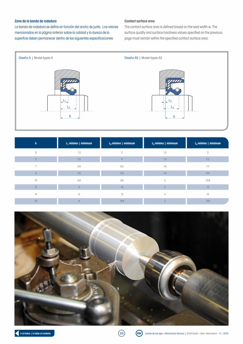
Zona de la banda de rodaduraLa banda de rodadura se define en función del ancho de junta. Los valores mencionados en la página anterior sobre la calidad y la dureza de la superficie deben permanecer dentro de las siguientes especificaciones:
Bearbeitung der WellenoberflächeVon zentraler Bedeutung für die Dichtfunktion ist die korrekte Bearbeitung der Lauffläche. Um Förder- bzw. Pumpwirkung und dadurch Leckagen an der Abdichtstelle zu verhindern, sollte die Welle im Laufflächenbereich der Dichtkante drallfrei und kreisrund bearbeitet sein.
Contact surface areaThe contact surface area is defined based on the seal width w. The surface quality and surface hardness values specified on the previous page must remain within the specified contact surface area:
Bearbeitung der WellenoberflächeVon zentraler Bedeutung für die Dichtfunktion ist die korrekte Bearbeitung der Lauffläche. Um Förder- bzw. Pumpwirkung und dadurch Leckagen an der Abdichtstelle zu verhindern, sollte die Welle im Laufflächenbereich der Dichtkante drallfrei und kreisrund bearbeitet sein.
b L1 mínimo | minimum L2 mínimo | minimum L3 mínimo | minimum L4 mínimo | minimum
3 1.3 2 1.2 3
5 2.5 4 1.4 5.2
7 3.6 6.2 1.6 7.7
8 3.6 6.9 1.6 8.4
10 4.6 8.6 2 10.6
12 5 10 2 12
15 6 12 3 15
20 9 16.6 3 10.6
b
L3L1
L4L2
b
Diseño A | Model types A Diseño AS | Model types AS

Juntas de los ejes - Información técnica | Shaft Seals – tech. information · 11 / 201521Ir al índice | to table of contents
Tipo de mecanizado
Mecanizado de la superficie del ejeDe importancia central para la función de sellado es un correcto mecanizado de la banda de rodadura. Para evitar el efecto de transporte y bombeo, evitando así fugas en el punto de cierre, el eje debe estar mecanizado sin torsión y de forma completamente circular en la banda de rodamiento del borde de sellado.
Torneado en duroEl torneado en duro es una opción muy común debido a su rentabilidad. El objetivo es crear una superficie de marcha opuesta utilizable. Para lograrlo, se cumplir ciertos parámetros de proceso tales como la velocidad de corte, la velocidad de alimentación, la profundidad de corte y el material.
Otras ventajas de este método de mecanizado son:• Reducido número de pasos de producción• Mecanizado completo en un solo paso de dotación de herramienta• Tiempos cortos de puesta a punto• Estructura de superficie bien definida del eje• Eliminación de masas de residuos de desbarbado
Los ejes fabricados por torneado presentan un efecto de transporte muy claro debido a la orientación de la corriente de deriva en superficie. El aceite es trans- portado en una u otra dirección dependiendo de la dirección de giro del eje.
El eje también debe ser capaz de transportar el fluido en direcciones de flujo alternantes y en contra de la dirección de sellado. Este es un hecho al que se debe prestar especial atención al seleccionar la junta de sellado del eje. Por esta razón, un eje torneado en duro sólo debe usarse si se desea únicamente una dirección de giro, que es la dirección de transporte del eje en dirección a la cámara de aceite. Como alternativa se puede usar una junta para eje que pueda devolver la corriente de transporte del eje torneado en duro de vuelta a la cámara de aceite. Las juntas de ejes en ejes torneados en duro muestran un par de fricción de similar a las de los ejes pulidos.
Las pruebas realizadas con el tipo de eje seleccionado le garantizarán una fiabilidad óptima. Con este fin, ttv trabaja junto con los fabricantes y en colaboración con un instituto de investigación lleva cabo ensayos con diferentes diseños de juntas para eje.
Pulido monopuntoEl pulido sin avance axial del disco de pulido se denomina pulido monopunto. Este método se utiliza con frecuencia ya que puede crear una superficie de contacto opuesta completamente libre de irregularidades que produzcan deriva. Mediante intervalos de activación de 30 seg. se puede alcanzar un alto grado de seguridad. Con el fin de evitar cualquier tipo de deriva, el disco de pulido se procesa con un perfilador multigrano. Sin embargo, es importante asegurarse de que no se crea una relación de transmisión de número entero entre la velocidad del árbol (por ejemplo, 50 1/min) y la velocidad de giro del disco de pulido (por ejemplo, 1500 1/min). Por otros métodos, como chorro de arena, esmerilado, rectificado, pulido, lijado la fabricación de superficies adecuadas para juntas de ejes queda fuertemente condicionada. Antes de que las superficies de contacto fabricadas así se puedan utilizar deberán efectuarse siempre varias carreras de prueba.
Processing methods
Shaft surface processingIn order to ensure correct sealing function, it is essential that the contact sur-face is processed correctly. In order to prevent the feed or pumping effect and thereby leakages at the sealing point, the shaft should be processed such that it is non-spiralling and circular in the contact surface area of the sealing edge.
Hard-turningThe hard-turning processing method is chosen in particular because it is very economical. It aims to create a usable mating surface. In order to achieve this, very precise process parameters must be complied with, such as cutting speed, feed rate, cutting material or cutting depth.
Additional advantages of this processing method are:• Few production steps• Complete processing in one clamping position• Short set-up times• A precisely defined shaft surface structure• Elimination of the grinding-sludge removal step
Due to the orientation of the spiral, i.e. the processing tracks, rotation-processed shafts have a clear feed effect: The oil is fed in one direction or the other, depending on the rotation direction of the shaft.
With an alternating rotation direction, a shaft should also be able to provide a feed in the opposite direction to the sealing direction. Particular attention should be paid to this fact when selecting the shaft seal. A hard-turned shaft should therefore only be used is only one rotation direction is required, i.e. if the shaft is required to provide a feed in the direction of the oil chamber. One alternative would be a shaft seal that can transport the flow produced by the hard-turned shaft back into the oil chamber.Shaft seals demonstrate similar friction torque behaviour on hard-turned shafts as on ground shafts.
Carrying out test runs with the selected shaft ensures optimal functional reliability. With this in mind, ttv works with manufacturers and, together with a research institute, carries out test runs with a variety of different shaft seal models.
In-feed grindingGrinding where the grinding wheel is not fed in axially is called in-feed grinding. This is the most common processing method, because it creates a non-spiralling mating surface, and the 30-second spark-off time ensures high levels of safety. The grinding wheel is dressed using a multipoint dresser in order to prevent any spiralling. However, it must be ensured that there is not an integral transmission ratio between the speed of the shaft (e.g. 50 rpm) and the speed of the grinding wheel (e.g. 1500 rpm). Shaft seal mating surfaces that can be produced by additional processes such as abrasive blasting, reaming, honing, lapping or sanding are only suitable to a limited extent. A number of test runs must be carried out before using mating surfaces produced in this way.

Juntas de los ejes - Información técnica | Shaft Seals – tech. information · 11 / 201522Ir al índice | to table of contents
Superficie del eje Para evitar en el punto de sellado un efecto de transporte o bombeo que perjudique el funcionamiento de la junta de sellado y con ello provoque una fuga deberá tenerse vigilarse que la superficie del eje no dé lugar a derivas del fluido. Una superficie está libre de derivas cuando las marcas de mecanizado no tienen orientación alguna.
El llamado “método de hilo” permite comprobar si los ejes y los casquillos de protección de ejes están fabricados sin dar lugar a derivas y/o torsiones. Si no existen derivas, el hilo de prueba se desliza sin cambio de pista axial sobre la banda de rodadura humedecida. Si existen derivas, el hilo de prueba se moverá en función de la dirección de giro hacia la izquierda o derecha. Solo se puede lograr un resultado fiable cuando se respetan diferentes parámetros, como la velocidad de giro, el peso o el ángulo que abarca el hilo.
Un calibrador basado en el método de dispersión de luz es la alternativa ideal al método del hilo y también se utilizan en estructuras de múltiples dimensiones.
Materiales de los ejes En todos los materiales de superficie del eje, los valores requeridos de dureza y de calidad de la superficie deben mantenerse constantes en todo momento.
En los casos en que no sea posible por razones de diseño, fabricación o de rentabilidad fabricar el eje con las propiedades de la banda de rodadura requeridas, ttv pone a su disposición casquillos protectores de eje.
En lo que refiere a su adecuación a la función requerida hay que tener en cuenta que:• Si se cumplen los valores correspondientes a la dureza de la superficie,
los aceros templados y revenidos convencionales son adecuados como materiales para el eje.
• La banda de rodadura de las juntas sellantes del eje nunca puede presentar corrosión. Para el sellado de agua o medios acuosos deben usarse ejes de acero inoxidable, termoestable, de alta aleación.
• Los materiales de hierro fundido son sólo recomendables si no existen vacíos en el material y el tamaño de poro es de <0,05 mm.
• Los metales no ferrosos son adecuados sólo para aplicaciones menores y a bajas velocidades perimetrales.
Shaft surfaces In order to prevent a feed or pumping effect at the sealing point, which could impair the functionality of the shaft seal, thereby leading to a leak, it must be ensured that the shaft‘s contact surface area is manufactured such that it is non-spiralling. A surface is deemed non-spiralling if the processing tracks do not show any alignment.
The so-called thread method can be used to check whether shafts and shaft protection sleeves are non-spiralling. If they are non-spiralling, the test thread will slide onto the moistened contact surface without any axial change to the track. If a spiral formation is present, the test thread will move axially left or right, depending on the rotation direction. A reliable result can only be achieved if different parameters are observed, such as speed, weight or thread wrap-around angle.
Spiral-testing devices based on the scattered light method are the perfect alternative to the thread method and are also used with very small or very large spiralling structures.
Shaft materials The required hardness and surface quality values must be complied with for all shaft surface materials.
ttv provides shaft protection sleeves for those situations where it is not possible to provide the shafts with the required contact surface properties for constructional, process-related or economic reasons.
The following applies in terms of suitability:• Standard tempered steels are suitable shaft materials, provided that the
corresponding values for the surface hardness are complied with• Corrosion must not form in the contact surface area of the shaft seal
under any circumstances. Shafts made from stainless, temperable, highly alloyed steel must be used to seal watery media or water
• Cast iron materials are only partly suitable, provided that they are free from cavities and have a pore size of under < 0.05 mm.
• NE metals are only suitable for use with menial applications and at low circumferential speeds.
Pulido sin deriva | Non-spirally ground

Juntas de los ejes - Información técnica | Shaft Seals – tech. information · 11 / 201523Ir al índice | to table of contents
• En casos especiales, los ejes recubiertos de cerámica pueden utilizarse, pero sólo en el caso de que la superficie esté sellada y tenga un tamaño de poro de <0,05 mm. Otras condiciones son un buen agarre sobre el eje, así como el cumplimiento del acabado superficial necesario.
• Debido a la mala formación de la película lubricante y el desgaste irregular los ejes cromados en duro presentan posibilidades de uso limitadas. Sin embargo, a través de un pulido multipunto, la formación de la película lubricante se puede mejorar considerablemente.
• Los ejes de plástico son aptos pero sujetos también a ciertas condiciones. Debido a la baja conductividad térmica de los plásticos, la disipación de calor en el eje se ve perjudicada. Esto provoca un aumento significativo de la temperatura en el borde de sellado, lo cual puede dar lugar al ablandamiento o fusión del plástico.
Daños en el eje
Siempre se deberá evitar todo tipo de daños. Estos incluyen puntos de impacto, cavidades, acanaladuras, poros, arañazos y la corrosión en la superficie de contacto. Casi un tercio de todas las averías prematuras y las fugas se deben a un mecanizado de ejes incorrecto o a daños en el mismo.
Para evitar problemas use medios de transporte adecuados o forros de plástico para proteger los ejes desde la producción hasta el montaje final.
Excentricidad
La excentricidad dinámica debe mantenerse siempre lo más baja posible. De lo contrario, puede ocurrir que el saliente sellante no puede seguir al eje por efecto de su inercia. Esto crea una distancia excesiva entre el borde de sellado y el eje, provocando la fuga del medio. Para contrarrestarlo, la junta de sellado del eje debe colocarse cerca del cojinete y la holgura del cojinete ser lo más pequeña posible. La figura muestra los valores de excentricidad permitidos en función de la velocidad. El diseño de ttv para aplicaciones sometidas a presión cuenta con una unión mucho más rígida por lo que son válidas para valores sin límites concretos.
• Ceramic-coated shafts can also be used in special cases, but only with sealed surfaces and a pore size of under 0.05 mm. Additional requirements are good adhesion to the shaft and compliance with the required surface qualities
• Due to the associated poor formation of the film of lubricant and uneven wear, hard-chrome plated shafts are only suitable to a limited extent. However, retroactive in-feed grinding can improve the formation of the film of lubricant
• Plastic shafts are also only suitable to a limited extent. The very low thermal conductivity of plastics impairs the removal of heat via the shaft.This leads to a considerable increase in temperature at the sealing edge, which can cause the plastic to soften or melt.
Shaft damage
All forms of damage must be avoided at all costs. Types of damage include truncations, corrugations, cavities, pores, scratches and corrosion on the contact surface. Almost a third of all premature failures and leakages are due to incorrect shaft processing or shaft damage.
Suitable transportation devices or protective plastic covers protect the shafts from the production stage to the final assembly.
Eccentricity
The dynamic eccentricity or the shaft run-out must be kept as low as possible. Otherwise, the sealing lip may no longer be able to follow the shaft as a result of its inertia. This creates an overly large gap between the sealing edge and the shaft, through which the medium to be sealed can escape. In order to counteract this, the shaft seal should be fitted very close to the bearing, and the bearing play should be kept as low as possible. The illustration shows the permissible eccentricity values, depending on the speed. The connection on the pressurizable ttv model is substantially more rigid, so the restricted values apply for this model.
0.05
0 20 40 60 80 100 120
0.100.150.200.250.300.35
Tolerancia de concentricidad f en mm | Coaxiality tolerance f in mm
Velocidad en rev /min | Speed in rpmf
Juntas de los ejes - Información técnica | Shaft Seals – tech. information · 11 / 201524Ir al índice | to table of contents
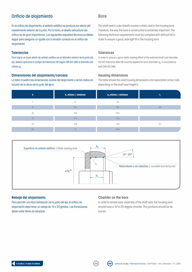
Orificio de alojamiento
En el orificio de alojamiento, el sellado estático se produce por efecto del revestimiento exterior de la junta. Por lo tanto, el diseño estructural del orificio es de gran importancia. Los siguientes requisitos técnicos se deben seguir para asegurar un ajuste con la tensión correcta en el orificio de alojamiento:
ToleranciasPara lograr un buen efecto de sellado estático en el diámetro exterior de la junta del
eje, deberá aplicarse el campo de tolerancia H8 según DIN ISO 286 al diámetro del
orificio dB .
Dimensiones del alojamiento/carcasaLa tabla muestra las dimensiones axiales del alojamiento y de los radios en función de la altura de la junta del eje b:
Rebaje del alojamientoPara permitir una fácil instalación de la junta del eje, el orificio de alojamiento debe tener un rebaje de 10 a 20 grados. Las transiciones deben estar libres de rebarbas.
Bore
The shaft seal‘s outer sheath causes a static seal in the housing bore. Therefore, the way the bore is constructed is extremely important. The following technical requirements must be complied with without fail in order to ensure a good, leak-tight fit in the housing bore:
TolerancesIn order to ensure a good static sealing effect at the external shaft seal diameter,
the ISO tolerance field H8 must be applied for bore diameter dB, in accordance
with DIN ISO 286.
Housing dimensionsThe table shows the axial housing dimensions and associated corner radii, depending on the shaft seal height b:
Chamfer on the boreIn order to enable easy assembly of the shaft seal, the housing bore should have a 10 to 20-degree chamfer. The junctions should be de-burred.
b1
b2
10°–20°
r1
Superficie de sellado estático | Static sealing area
Redondeado y sin rebarbas | rounded and de-burred
dBH8
b b1 mínimo | minimum b2 mínimo | minimum r1
7 6 7.4
8 6.9 8.4 0.5
10 8.6 10.4
12 10.4 12.4
15 12.8 15.4 0.7
20 17 20.4
Juntas de los ejes - Información técnica | Shaft Seals – tech. information · 11 / 201525Ir al índice | to table of contents
Calidad de la superficie del orificioLos siguientes valores de rugosidad deben cumplirse para lograr un buen sellado estático y un ajuste a presión seguro en el orificio del alojamiento:
Valores permitidos para diseños con camisa exterior de caucho A / ASRa = 1,6 hasta 6,3 µmRz = 10 hasta 20 µmRmax = ≤ 25 µm
Valores en diseños con cubierta exterior metálica B / BS, C / CSRa = 0,8 hasta 3,2 µmRz = 6,3 hasta 16 µmRmax = ≤ 16µm
Las juntas de eje con camisa metálica exterior y / o inserto combinado con líquidos o gases de baja densidad necesitan un excelente acabado de superficie. Eso significa que la superficie en el orificio de alojamiento no deberá tener daños como arañazos y marcas de mecanizado, impactos, surcos o cavidades.
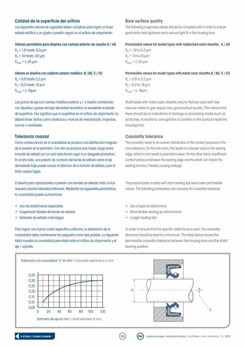
Tolerancia coaxialComo consecuencia de la coaxialidad se produce una distribución irregular de la presión en el perímetro. Con ello se produce una mayor carga sobre le borde de sellado por un solo lado,dando lugar a un desgaste prematuro. En el otro lado, una presión de contacto del borde de sellado sobre el eje demasiado baja puede causar el deterioro de la función de sellado y por lo tanto causar fugas.
El diseño para aplicaciones a presión con bordes de sellado más cortos requiere valores tolerados inferiores. Mediante los siguientes parámetros, la coaxialidad puede aumentarse:
• Uso de elastómeros especiales• Suspensión flexible del borde de sellado• Salientes de sellado más largos
Para lograr una fuerza radial específica uniforme, la desviación de la coaxialidad debe mantenerse tan pequeña como sea posible. La siguiente tabla muestra la coaxialidad permitida entre el orificio de alojamiento y el eje / cojinete.
Bore surface qualityThe following roughness values should be complied with in order to ensure good static leak-tightness and a secure tight fit in the housing bore:
Permissible values for model types with rubberised outer sheaths, A / ASRa = 1.6 to 6.3 µmRz = 10 to 20 µmRmax = ≤ 25 µm
Permissible values for model types with metal outer sheaths B / BS, C / CSRa = 0.8 to 3.2 µmRz = 6.3 to 16 µmRmax = ≤ 16µm
Shaft seals with metal outer sheaths and/or that are used with low-viscous media or gas require very good surface quality. This means that there should be no indications of damage or processing tracks such as scratches, truncations, corrugations or cavities on the surface inside the housing bore.
Coaxiality toleranceThe coaxiality leads to an uneven distribution of the contact pressure in the circumference. On the one hand, this leads to a heavier load on the sealing edge, which in turn leads to premature wear. On the other hand, insufficient contact pressure between the sealing edge and the shaft can impair the sealing function, thereby causing leakage.
The pressurizable models with short sealing lips need lower permissible values. The following parameters can increase the coaxiality tolerance:
• Use of special elastomers• More flexible sealing lip attachments• Longer sealing lips
In order to ensure that the specific radial force is even, the coaxiality deviance should be kept to a minimum. The table below shows the permissible coaxiality tolerance between the housing bore and the shaft/bearing position.
Tolerancia a la coaxialidad “e” en mm | Coaxiality tolerance e in mm
Diámetro del eje en mm | shaft diameter in mm
0,050 20 40 60 80 100 120
0,100,150,200,250,300,35
e
Juntas de los ejes - Información técnica | Shaft Seals – tech. information · 11 / 201526Ir al índice | to table of contents
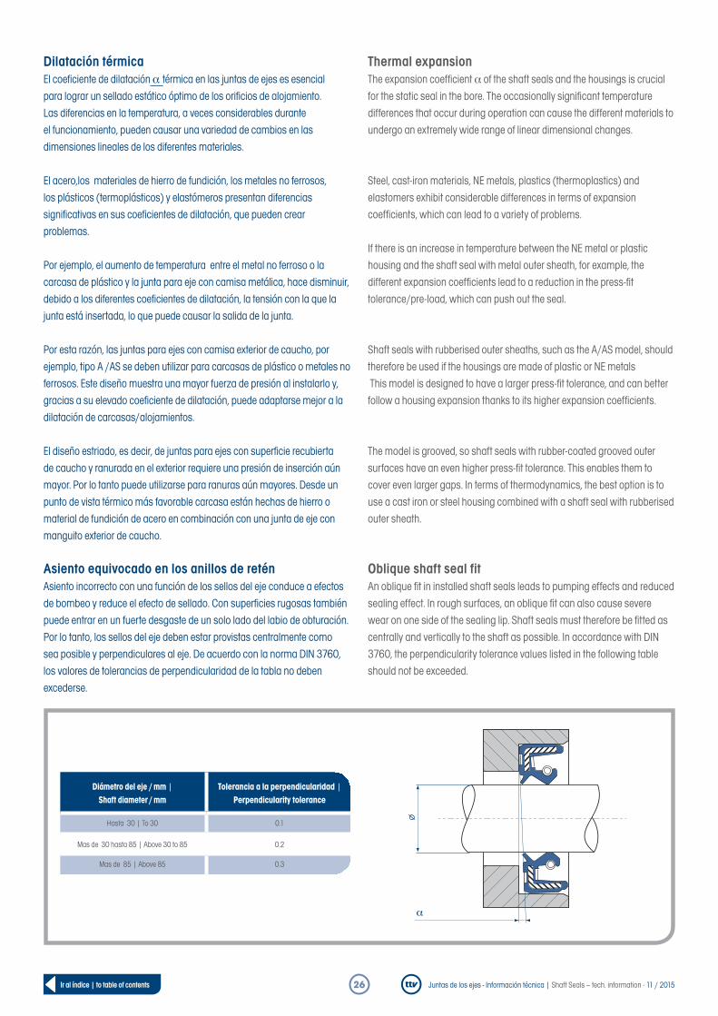
Dilatación térmicaEl coeficiente de dilatación a térmica en las juntas de ejes es esencial para lograr un sellado estático óptimo de los orificios de alojamiento. Las diferencias en la temperatura, a veces considerables durante el funcionamiento, pueden causar una variedad de cambios en las dimensiones lineales de los diferentes materiales.
El acero,los materiales de hierro de fundición, los metales no ferrosos, los plásticos (termoplásticos) y elastómeros presentan diferencias significativas en sus coeficientes de dilatación, que pueden crear problemas.
Por ejemplo, el aumento de temperatura entre el metal no ferroso o la carcasa de plástico y la junta para eje con camisa metálica, hace disminuir, debido a los diferentes coeficientes de dilatación, la tensión con la que la junta está insertada, lo que puede causar la salida de la junta.
Por esta razón, las juntas para ejes con camisa exterior de caucho, por ejemplo, tipo A /AS se deben utilizar para carcasas de plástico o metales no ferrosos. Este diseño muestra una mayor fuerza de presión al instalarlo y, gracias a su elevado coeficiente de dilatación, puede adaptarse mejor a la dilatación de carcasas/alojamientos.
El diseño estriado, es decir, de juntas para ejes con superficie recubierta de caucho y ranurada en el exterior requiere una presión de inserción aún mayor. Por lo tanto puede utilizarse para ranuras aún mayores. Desde un punto de vista térmico más favorable carcasa están hechas de hierro o material de fundición de acero en combinación con una junta de eje con manguito exterior de caucho.
Asiento equivocado en los anillos de reténAsiento incorrecto con una función de los sellos del eje conduce a efectos de bombeo y reduce el efecto de sellado. Con superficies rugosas también puede entrar en un fuerte desgaste de un solo lado del labio de obturación. Por lo tanto, los sellos del eje deben estar provistas centralmente como sea posible y perpendiculares al eje. De acuerdo con la norma DIN 3760, los valores de tolerancias de perpendicularidad de la tabla no deben excederse.
Thermal expansionThe expansion coefficient a of the shaft seals and the housings is crucial for the static seal in the bore. The occasionally significant temperature differences that occur during operation can cause the different materials to undergo an extremely wide range of linear dimensional changes.
Steel, cast-iron materials, NE metals, plastics (thermoplastics) and elastomers exhibit considerable differences in terms of expansion coefficients, which can lead to a variety of problems.
If there is an increase in temperature between the NE metal or plastic housing and the shaft seal with metal outer sheath, for example, the different expansion coefficients lead to a reduction in the press-fit tolerance/pre-load, which can push out the seal.
Shaft seals with rubberised outer sheaths, such as the A/AS model, should therefore be used if the housings are made of plastic or NE metals This model is designed to have a larger press-fit tolerance, and can better follow a housing expansion thanks to its higher expansion coefficients.
The model is grooved, so shaft seals with rubber-coated grooved outer surfaces have an even higher press-fit tolerance. This enables them to cover even larger gaps. In terms of thermodynamics, the best option is to use a cast iron or steel housing combined with a shaft seal with rubberised outer sheath.
Oblique shaft seal fitAn oblique fit in installed shaft seals leads to pumping effects and reduced sealing effect. In rough surfaces, an oblique fit can also cause severe wear on one side of the sealing lip. Shaft seals must therefore be fitted as centrally and vertically to the shaft as possible. In accordance with DIN 3760, the perpendicularity tolerance values listed in the following table should not be exceeded.
a
Diámetro del eje / mm | Shaft diameter / mm
Tolerancia a la perpendicularidad | Perpendicularity tolerance
Hasta 30 | To 30 0.1
Mas de 30 hasta 85 | Above 30 to 85 0.2
Mas de 85 | Above 85 0.3
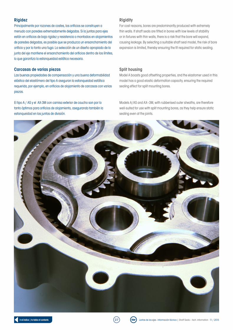
Juntas de los ejes - Información técnica | Shaft Seals – tech. information · 11 / 201527Ir al índice | to table of contents
RigidezPrincipalmente por razones de costes, los orificios se construyen a menudo con paredes extremadamente delgadas. Si la juntas para ejes están en orificios de baja rigidez y resistencia o montados en alojamientos de paredes delgadas, es posible que se produzca un ensanchamiento del orificio y por lo tanto una fuga. La selección de un diseño apropiado de la junta del eje mantiene el ensanchamiento del orificios dentro de los límites, lo que garantiza la estanqueidad estática necesaria.
Carcasas de varias piezasLas buenas propiedades de compensación y una buena deformabilidad elástica del elastómero del tipo A aseguran la estanqueidad estática requerida, por ejemplo, en orificios de alojamiento de carcasas con varias piezas.
El tipo A / AS y el AX-3M con camisa exterior de caucho son por lo tanto óptimos para orificios de alojamiento, asegurando también la estanqueidad en las juntas de división.
RigidityFor cost reasons, bores are predominantly produced with extremely thin walls. If shaft seals are fitted in bores with low levels of stability or in fixtures with thin walls, there is a risk that the bore will expand, causing leakage. By selecting a suitable shaft seal model, the risk of bore expansion is limited, thereby ensuring the fit required for static sealing.
Split housingModel A boasts good offsetting properties, and the elastomer used in this model has a good elastic deformation capacity, ensuring the required sealing effect for split mounting bores.
Models A/AS and AX–3M, with rubberised outer sheaths, are therefore well-suited for use with split mounting bores, as they help ensure static sealing even at the joints.

Juntas de los ejes - Información técnica | Shaft Seals – tech. information · 11 / 201528Ir al índice | to table of contents
7. Instrucciones de instalación Cumpla las siguientes reglas al instalar juntas de sellado para eje:
• Se ha de garantizar una adecuada lubricación y engrase de la junta del eje
• Todos los elementos, como el eje, el orificio y la junta sellante deben estar limpios
• Las transiciones deben estar redondeadas y libres de rebarbas• La junta dell eje no debe cantear cuando se la somete a presión• La junta del eje se debe montar en paralelo al eje• Los daños en el saliente sellante, por ejemplo, producidos por
engranajes y otras transiciones deben evitarse siempre
Montaje de una junta sellante partiendo de los gráficos de referencia:
7. Installation instructions The following rules apply to the installation of shaft seals:
• It must be ensured that the shaft and shaft seal are sufficiently greased or lubricated
• All components, such as the shaft, bore and seal ring, must be clean• Junctions must be rounded and de-burred• The shaft seal should not be tilted when it is pressed in• The shaft seal should be installed parallel to the shaft• Damage to the sealing lip, due to gearwheels or other junctions for
example, must be avoided
Using diagrams to install a shaft seal:
Ayudas de montaje | Installation aids
Correcto | Correct Falso | Incorrect
D = D - 0.5
D
Diámetro demasiado pequeño | Diameter too small
5° – 10°
min. 1mm
Pieza de empuje | Thrust piece
Camisa del ejeShaft protection sleeve
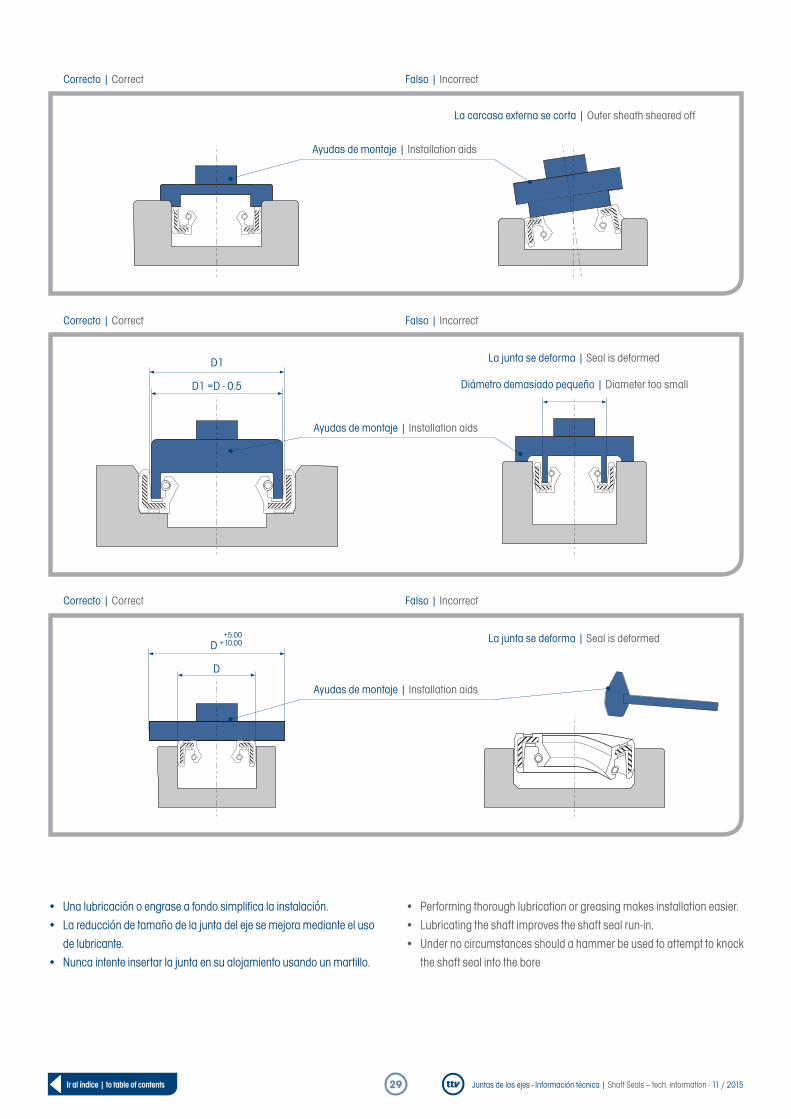
Juntas de los ejes - Información técnica | Shaft Seals – tech. information · 11 / 201529Ir al índice | to table of contents
• Una lubricación o engrase a fondo simplifica la instalación.• La reducción de tamaño de la junta del eje se mejora mediante el uso
de lubricante.• Nunca intente insertar la junta en su alojamiento usando un martillo.
• Performing thorough lubrication or greasing makes installation easier.• Lubricating the shaft improves the shaft seal run-in.• Under no circumstances should a hammer be used to attempt to knock
the shaft seal into the bore
La carcasa externa se corta | Outer sheath sheared off
Correcto | Correct Falso | Incorrect
Ayudas de montaje | Installation aids
La junta se deforma | Seal is deformed
Correcto | Correct Falso | Incorrect
D
+5.00D +10.00
Ayudas de montaje | Installation aids
D1 =D - 0.5
D1 La junta se deforma | Seal is deformed
Correcto | Correct Falso | Incorrect
Diámetro demasiado pequeño | Diameter too small
Ayudas de montaje | Installation aids

Juntas de los ejes - Información técnica | Shaft Seals – tech. information · 11 / 201530Ir al índice | to table of contents
Ayudas de montaje
La instalación incorrecta o el uso de herramientas de ayuda para la insta- lación indebidas son la causa de aproximadamente un tercio de todos los daños y fallos en juntas para ejes. Por lo tanto, una instalación absoluta-mente correcta de acuerdo con la norma DIN 3760 es de vital importancia.
El espacio de instalación y la junta sellante deben limpiarse a fondo antes de la instalación, ya que las partículas de suciedad pueden dar lugar a fugas transcurrido poco tiempo. Es imprescindible tener en cuenta las instrucciones de instalación que le proporciona ttv.
Para presionar las juntas para eje en el orificio del alojamiento resultan óptimos sistemas de prensa hidráulica o mecánica. Con el objetivo de lograr una alta fuerza de presión sobre el diámetro exterior, el sistema de prensa debe presionar una amplia zona en el exterior de la junta del eje. En este caso, la herramienta de presión se debe mantener durante un tiempo en la posición final para evitar inclinaciones o movimientos elásticos de la junta contrarios a la dirección de presión.
Si es necesario guiar las juntas sobre elementos afilados como roscas, ranuras o extremos de eje se deben usar casquillos de montaje, libres de daños, como arañazos y/o superficies rugosas.
Para asegurar un ajuste con la tensión necesaria se debe asegurar que la camisa exterior está en contacto completamente con el orificio de alojamien-to. Cuando el rebaje frontal de la junta sobresale sólo ligeramente del rebaje de la carcasa/alojamiento puede darse una reducción de la adhe-sión, y dar lugar a movimientos no deseado de la junta de sellado en su orificio.
Si se va a rellenar con grase entre el saliente de protección contra el polvo y el de estanqueidad, el espacio intermedio debe llenarse hasta dos tercios y cubrirse correctamente. Las ayudas de instalación, tales como cepillos o pinceles pueden dejar residuos en la junta, lo que interfiere en su correcto funcionamiento.
Installation aids
Almost a third of all shaft seal damage and failure is caused by incorrect installation or the use of unsuitable installation aids. It is therefore essential that the shaft seals be installed correctly in accordance with DIN 3760.
The installation area and the shaft seal must be thoroughly cleaned prior to installation, as adherent dirt particles can quickly cause leakages.The ttv installation instructions must be observed without fail.
A hydraulic or mechanical press-in tool is the most suitable device for pressing the shaft seal into the housing bore. In order to achieve the highest possible pressing force at the external diameter, the press-in tool must be placed with a large proportion of its surface area on the outside of the shaft seal. During this press-in process, the press-in tool must be held in the final position for some time, in order to minimise the risk of the shaft seal springing back or exhibiting any obliqueness.
If it is necessary to pass the shaft seal over any sharp edges, such as threads, grooves or shaft ends, then suitable installation sleeves must be provided. These sleeves must not be damaged and must not feature any rough surfaces or scratches.
In order to guarantee a secure fit, it must be ensured that the outer sheath is placed fully against the housing bore. If the front chamfer of the shaft seal protrudes only slightly over the housing chamfer, this can reduce the extent of the adhesion and lead to unwanted movement of the shaft seal inside the bore.
If the area between the dust lip and the sealing lip is to be filled with grease, then only two-thirds of this area should be filled, and the application of the grease must be carried out in a specified manner. Application aids such as brushes can leave residue on the seal, which can impair its functionality.
Sistemas de ayuda para la instalación | Possible installation aids

Juntas de los ejes - Información técnica | Shaft Seals – tech. information · 11 / 201531Ir al índice | to table of contents
Juntas de ejes hechas de politetrafluoroetileno (PTFE)Si el elemento de PTFE se incorpora a través de un rebaje del eje, deberá instalarse también un cono de montaje para guiar el saliente sellante y evitar su plegado.
Si se montan productos de la serie M01 | M02 en el lado exterior primero, deberá preverse un empalme o chaflán tiene que ser proporcionado. De lo contrario, se aplican las directrices habituales para la instalación de anillos de obturación de eje. Indicaciones para la inclinación de montaje “d2”, ver tabla.
Shaft seals made from polytetrafluoroethylene (PTFE)If PTFE is fitted over a chamfered shaft, an installation cone must be provided in order to guide the sealing lip and prevent it from collapsing downwards.
If M01|M02 is installed with the outer side facing forwards, a chamfer or rounded-edge must be provided. Otherwise, the usual guidelines for the installation of shaft seals apply. See table for information on the installation “d2”.
15° – 20°
d1 d2R ≤ 0.6
d1 d2
5 – 65 d1 - 4
65 – 140 d1 - 5
140 – 180 d1 - 7

Juntas de los ejes - Información técnica | Shaft Seals – tech. information · 11 / 201532Ir al índice | to table of contents
8. Consejos útiles para el almace- namiento de productos elastómeros
También en el almacenamiento durante varios años, las propiedades de los elastómeros permanecen casi sin cambios. Un requisito previo para esto es que los requisitos mínimos establecidos en la norma DIN 7716 e ISO 2230 se cumplan.
Para ello es esencial almacenar las juntas en un lugar seco, fresco, libre de polvo y sin presiones, tracciones u otros efectos mecánicos, idealmente en un recipiente hermético, como en bolsas de polietileno.
Para los espacios donde se almacenan los elastómeros vigile que:
• Hay una temperatura constante entre -10 y +20 ° C• Hay una ventilación moderada de la sala de almacenamiento• Evite corrientes de aire• Evite los cambios bruscos de temperatura• Evite la exposición excesiva a la luz, particularmente la radiación UV• Evite la luz solar directa• Humedad relativa de no más del 65%• vite dispositivos eléctricos generadores de ozono• La distancia mínima de almacenado es de al menos 1 metro respecto
a los elementos que generan calor
Para más información sobre el almacenamiento de juntas sellantes para ejes, consulte el centro de descarga en www.ttv-gmbh.de.
9. Aplicaciones de Materiales
1 = muy bueno / 2 = bueno / 3 = moderado | 1 = very good / 2 = good / 3 = moderate
8. Information on storing elastomer products
Elastomer properties remain almost unchanged, even when stored for many years. In order for this to be the case, however, the minimum storage condition requirements set out in DIN 7716 and ISO 2230 must be complied with.
It is extremely important that the seals are stored in a cool, dry location that is as free from dust as possible, and where they are not subjected to any pressure, tension or other mechanical influences. Ideally, they should be stored in air-tight packaging, such as polyethylene bags.
The following rules apply for areas where elastomers are stored:
• A constant temperature between -10 and +20 °C should be maintained• Reasonable ventilation of the storage area should be ensured• Draughts should be avoided• Extreme temperature changes should be avoided• Extreme light exposure—particularly UV radiation—should be avoided• Direct sunlight should be avoided• A relative humidity of no more than 65% should be ensured• No ozone-generating electrical equipment should be present• There should be a minimum distance of 1 m from the stored items to
the radiator
Additional information on storing shaft seals can be found in the Download centre at www.ttv-gmbh.de.
9. Fields of application for the materials
Material | Material NBRNBR (alta temp.)
NBR (High Nitrile)NBR (baja temp.
NBR (High Nitrile)HNBR ACM FPM
Silicona Silicon
PTFE
Temperatura más baja
Lowest temperature–30 –30 –50 –40 –25 –30 –50 –80
Temperatura máxima (sin influencia de los
medios lubricantes) | Highest temperature
(without influence of media)
+100 +120 +90 +150 +150 +200 +200 +200
Resistencia a la abrasión
Abrasion resistance2 2 2 1–2 3 1–2 3 3

Juntas de los ejes - Información técnica | Shaft Seals – tech. information · 11 / 201533Ir al índice | to table of contents
Medios a sellar – temperatura constante permitida (°C) Media to be sealed – permissible permanent temperature (°C)
Líquidos hidráulicos antiinflamables según VDMA 24317 / 24320
Low-flammability pressurised liquids VDMA 24317 / 24320
Otros medios Other media
= Resistente pero no se utiliza | Resistant, but not used = Sólo parcialmente resistente | Only resistant to a limited extent
– = No es resistente | Not resistant
Aceites mineralesMineral oils
NBRNBR (alta temp.)
NBR (High Nitrile)NBR (baja temp.
NBR (High Nitrile)HNBR ACM FPM
Silicona Silicon
PTFE
Aceites de motor | Engine oils +100 +100 +90 +100 +130 +150 +130 +150
Aceites para engranajes | Gearbox oils +80 +80 +70 +80 +120 +150 +130 +150
Aceites para engranajes hipoides
Hypoid gearbox oils+80 +80 +70 +80 +120 +140 – +150
Aceites ATF |ATF oils +100 +100 +80 +100 +130 +150 +150
Líquidos de circuitos a presión DIN51524
Pressurised fluids as per DIN51524+90 +90 +80 +90 +120 +130 +150
Aceites calefactores EL y L
EL and L fuel oils+90 +90 +80 +150 +150
Materias grasas | Greases +90 +90 +80 +90 +120 +150 +150
NBRNBR (alta temp.)
NBR (High Nitrile)NBR (baja temp.
NBR (High Nitrile)HNBR ACM FPM
Silicona Silicon
PTFE
HFA – emulsiones de aceite en agua
HFA – oil in water emulsions+60 +60 +60 – +150
HFB – emulsiones de agua en aceite
HFB – water in oil emulsions+60 +60 +60 – +150
HFC – agua en emulsiones de aceite
HFC – water in oil emulsions+60 +60 +60 – +140
HFD – fluidos sintéticos anhídricos
HFD – anhydrous synthetic liquids– – – – – +150 +150
NBRNBR (alta temp.)
NBR (High Nitrile)NBR (baja temp.
NBR (High Nitrile)HNBR ACM FPM
Silicona Silicon
PTFE
Agua | Water +80 +80 +90 – +80
Soluciones de detergentes | Suds +80 +80 +90 – +80

Juntas de los ejes - Información técnica | Shaft Seals – tech. information · 11 / 2015
technische teile vertrieb GmbH · Josef-Henle-Str. 9e · D-89257 Illertissen · Tel. +49 (0) 7303 - 92874 - 0 · Fax +49 (0) 7303 - 92874 - 50 · [email protected] · www.ttv-gmbh.de