
MANUAL DE INSTRUCCION - we.com.pa · Inspeccionar la máquina para llevado, suelto, o partes...
26
MANUAL DE INSTRUCCION TR18346 MOTO SIERRA A GASOLINA Nota: Antes de usar nuestra sierra de cadena. por favor leer este manual cuidadosamente para entender el uso apropiado de vuestra unidad. Mantener este manual para futuras consultas. 3,000 rpm ML 550 FUEL TANK TANQUE DE GASOLINA 0.325" CHAIN CADENA 45.8 ENGINE MOTOR CC ESPADA ESPADA 405 mm
Transcript of MANUAL DE INSTRUCCION - we.com.pa · Inspeccionar la máquina para llevado, suelto, o partes...

MANUAL DE INSTRUCCION
TR18346 MOTO SIERRA A GASOLINA
Nota: Antes de usar nuestra sierra de cadena. por favorleer este manual cuidadosamente para entender el usoapropiado de vuestra unidad. Mantener este manual parafuturas consultas.
3,000rpmML
550
FUEL TANKTANQUE DEGASOLINA
0.325"
CHAINCADENA
45.8
ENGINEMOTOR
CCESPADAESPADA
405 mm
SEGURIDAD PRIMERO
CONTENIDO
1. UBICACIÓN DE PARTES.....................................................................2
2. ADVIRTIENDO ETIQUETAS EN LA MÁQUINA.....................................2
3. SÍMBOLOS EN LA MÁQUINA...............................................................3
4. SEGURIDAD Y PRECAUCIONES........................................................3
5. INSTALANDO BARRA DE GUÍA Y SIERRA CADENA..................... .....7
6. COMBUSTIBLE Y ENGRASE DE CADENA.........................................9
7. MOTOR OPERATIVO..........................................................................10
8. ASERRANDO.......................................................................................14
9. MANTENIMIENTO...............................................................................16
10. MANTENIMIENTODE SIERRACADENAY BARRADE GUÍA............18
11. ESPECIFICACIONES........................................................................20
Las instrucciones contuvieron en avisos dentro de este manual marcado con una preocupación de símbolo puntos críticos que tienen que ser tomado aconsideración para impedir posible serio bodily daño , y para esta razónestás pedido para leer todas tales instrucciones se preocupan plenamente yseguirles sin fallar.
NOTAS EN TIPOS DE AVISOS EN EL MANUAL
Esta marca indica instrucciones que tienen que ser seguido para impediraccidentes que podrían dirigir a serio bodily daño o muerte..
Esta marca indica instrucciones que tienen que ser seguido, o dirige a fracasomecánico, desglose, o daño..
Esta marca indica las pistas o las direcciones útiles en el uso del producto.
NOTA
IMPORTANTE
AVISO
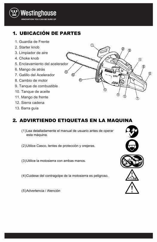
1. UBICACIÓN DE PARTES
2. ADVIRTIENDO ETIQUETAS EN LA MAQUINA
(1)Lea detalladamente el manual de usuario antes de operaresta máquina.
(2)Utilice Casco, lentes de protección y orejeras.
(3)Utilice la motosierra con ambas manos.
(4)Cuidese del contragolpe de la motosierra es peligroso.
(5)Advertencia / Atención !
1. Guardia de Frente2. Starter knob3. Limpiador de aire4. Choke knob5. Enclavamiento del acelerador6. Mango de atrás7. Gatillo del Acelerador8. Cambio de motor9. Tanque de combustible10. Tanque de aceite11. Mango de frente12. Sierra cadena13. Barra guía
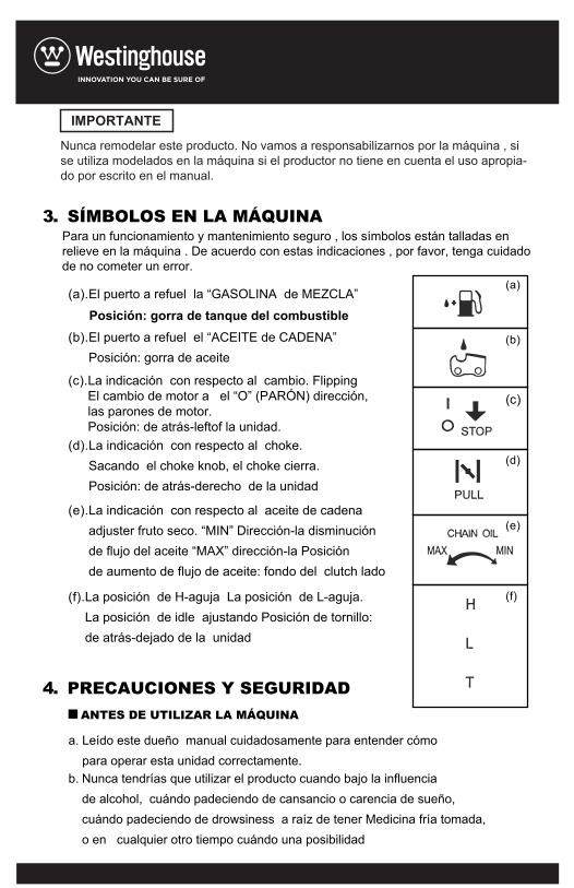
(a).El puerto a refuel la “GASOLINA de MEZCLA”
Posición: gorra de tanque del combustible(b).El puerto a refuel el “ACEITE de CADENA”
Posición: gorra de aceite
(c).La indicación con respecto al cambio. FlippingEl cambio de motor a el “O” (PARÓN) dirección,las parones de motor.Posición: de atrás-leftof la unidad.
(d).La indicación con respecto al choke.Sacando el choke knob, el choke cierra.Posición: de atrás-derecho de la unidad
(e).La indicación con respecto al aceite de cadenaadjuster fruto seco. “MIN” Dirección-la disminución de flujo del aceite “MAX” dirección-la Posiciónde aumento de flujo de aceite: fondo del clutch lado
(f).La posición de H-aguja La posición de L-aguja. La posición de idle ajustando Posición de tornillo:de atrás-dejado de la unidad
a. Leído este dueño manual cuidadosamente para entender cómopara operar esta unidad correctamente.
b. Nunca tendrías que utilizar el producto cuando bajo la influencia de alcohol, cuándo padeciendo de cansancio o carencia de sueño,cuándo padeciendo de drowsiness a raíz de tener Medicina fría tomada,o en cualquier otro tiempo cuándo una posibilidad
3. SÍMBOLOS EN LA MÁQUINA
4. PRECAUCIONES Y SEGURIDADANTES DE UTILIZAR LA MÁQUINA
(a)
(b)
(d)
(e)
(f)
(c)
Nunca remodelar este producto. No vamos a responsabilizarnos por la máquina , si se utiliza modelados en la máquina si el productor no tiene en cuenta el uso apropia-do por escrito en el manual.
Para un funcionamiento y mantenimiento seguro , los símbolos están talladas en relieve en la máquina . De acuerdo con estas indicaciones , por favor, tenga cuidado de no cometer un error.
IMPORTANTE
Existe que vuestro juicio podría ser impaired o que no podrías sercapaz de operar la máquina correctamente y en un seguromanner.
c. Evita correr el motor en interiores. El agotar los gases contienenmonóxido de carbono nocivo.
d. Nunca utilizar el producto bajo las circunstancias comoaquellas describieron abajo:1. Cuándo la tierra es resbaladiza o cuándo otras condicionesexistenCuál lo podría hacer no posible de mantener un steady postura2. Por la noche, en tiempo de niebla pesada, o en cualquier otrotiempo cuando Vuestro campo de visión podría ser limitado y sería difícil de obtener una vista clara del área.. 3. Durante tormentas de lluvia, durante tormentas de relámpago,en tiempo de fuerte o vendaval-vientos de fuerza, o en cualquierotro tiempo cuándo condiciones de tiempo lo podrían hacer unsafepara utilizar este producto.
e. Cuándo utilizando este producto por primera vez, antes de empezar. Trabajo real, lean a manejarlo de trabajador especializado.
f. Carencia de sueño, tiredness, o físico exhaustion resultados enatención más baja spans, y esto en ventajas de vuelta a accidentes y daño. Límite la cantidad de tiempo de utilizar la máquinacontinuamente a somewhere alrededor de 10 minutos por sesión,y toma 1,020 minutos de resto entre sesiones de trabajo.También intentar mantener la cantidad total del trabajo actuadoen un día solo bajo 2 horas o menos.
g. Ser seguro para mantener este manual manejable de modo quepuedes referir a él más tarde whenever cualesquier cuestionessurgen.
h. Siempre ser seguro para incluir este manual cuándo vendiendo,dejando, u otherwise transfiriendo la propiedad del producto.
I. Nunca dejar niños o cualquiera incapaz a plenamente entenderlas direcciones dadas en este manual de utilizar este producto.
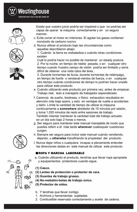
a. Cuándo utilizando el producto, tendrías que llevar ropa apropiaday equipamientos protectores cuando sigue.
b. Y tendrías que llevar contigo. 1. Archivos y herramientas sujetadas.2. Combustible reservado correctamente y aceite de cadena.
(1) Casco.(2) Lentes de protección o protector de cara.(3) Guantes de trabajo grueso.(4) No-resbalón-botas de trabajo único.(5) Protector de oídos.
ROPA Y MARCHA LABORABLE
3. Cosas para notificar vuestra área laborable (Cuerda, advirtiendo señales)4.Pito (para colaboración o emergencia). 5. Hatchet O sierra (para extracción de obstáculos).
c. Nunca utilizar el producto cuándo llevando pantalones con suelto cuffs, cuándo llevando sándalos, o cuándo barefoot.
LABORABLE CONSIDERANDO MANEJANDO DE COMBUSTIBLE.
El motor de este producto está diseñado para correrEn un combustible mixto que contiene altamente gasolina inflamable. Nunca latas de tienda de combustible o recambio. El tanque de combustible en cualquier sitio donde hay una estufa de caldera, fuego de madera, chispas eléctricas, chispas de soldadura,O cualquiera otra fuente de calor o fuego que podrían incendiar el combustible.Fumando mientras operando el producto o refilling su tanque de combusti-ble es extremadamente peligroso. Siempre ser seguro para mantener cigarrillos encendidos fuera de el producto nada tiempo.Cuándo refilling el tanque siempre apaga el motor primero y tomar una mirada prudente alrededor para hacer seguro que no hay ninguna chispa o llamas abiertas anywhere cercano antes de refueling.. Si cualquier combustible spillage ocurre durante refueling, uso un seco rag a wipe arriba de derrames antes de girar el motor atrás en otra vez.Después de refueling, tornillo la gorra de combustible respalda estrecha-mente al tanque de combustible y entonces llevar el producto a un sitio 3 m o más fuera de dónde era refueled antes de girar en el motor.
ANTES DE ARRANCAR MOTORControl sitio laborable, el objeto tajante y dirección tajante. Si hay obstácu-lo, sacarlo.Nunca empieza cortar hasta que tienes una área de trabajo clara, seguro footing y un camino de retiro planeado del árbol de caer.Uso caution y mantener by standers y animales fuera de el área laborable cuyo diámetro es 2.5 tiempo del objeto tajante.Inspeccionar la máquina para llevado, suelto, o partes averiadas. Nunca operar la máquina que está averiada, impropiamente ajustado, o no es completamente y securely reunió. Marca seguro que el sierra la cadena para mover cuándo el throttle gatillo de control está liberado.
a.
b.
c.
d.
e.
●
●
●
●
Antes de empezar el motor, marca seguro el sierra la cadena no está contactando cualquier cosa.OPERACIÓNMantener los mangos secos, limpio y libre de aceite o combustible mixture.Nunca tocar el muffler, tapón de chispa u otras partes metálicas del motor mientras el motor es en operación o inmediatamente después de parar el motor. Haciendo así que podría resultar en serio bums o shock eléctrico.El uso extremo caution cuándo cortando cepillo de medida pequeña y plantones. Porque slender el material puede coger el sierra cadena y ser whipped toward te o estirarte de equilibrio.. Cuándo cortando un limb que es bajo tensión, ser alerta para primavera atrás aAquello no serás golpeado cuándo la tensión en las fibras de madera está liberada control el árbol para ramas muertas que podrían caer durante el felling operación.Siempre cerrado del motor antes de ponerlo abajo.
KICKBACK SEGURIDAD PRECAUTIONS PARA la cadena VIO USUARIOSKickback Puede ocurrir cuándo la nariz o el consejo de la barra de guía toca un objeto, o cuándo la madera cierra dentro y pellizca el sierra cadena en el corte. Contacto de consejo en algunos casos puede causar un relámpago reacción inversa rápida, chutando la barra de guía arriba de y atrás hacia el operador. Pellizcando el sierra cadena a lo largo de la parte superior de la barra de guía puede empujar la barra de guía rápidamente atrás hacia el operador. Cualesquiera de estas reacciones te pueden causar para perder control del sierra que podría resultar en daño personal serio.No confía exclusivamente en el sin incidentes los dispositivos constru-yeron a vuestro vio. Como la cadena sierra usuario tendrías que tomar varios pasos para mantener trabajos tajantes gratis de accidente o daño..
Do not overreach or cut above shoulder height.Follow manufactures sharpening and maintenanceinstructions for saw chain.Only use replacement bars and chains specified by themanufacturer or the equivalent.
In order to maintain your product in proper working order,perform the maintenance and checking operationsdescribed in the manual at regular intervals.Always be sure to turn off the engine before performingand maintenance or checking procedures.
Leave all maintenance other than the items listed in theOwner’s Manual to your competent servicing dealer.
Always carry the unit with the engine stopped, theguide bar covered with the protector to the rare , andmuffler away from your body.
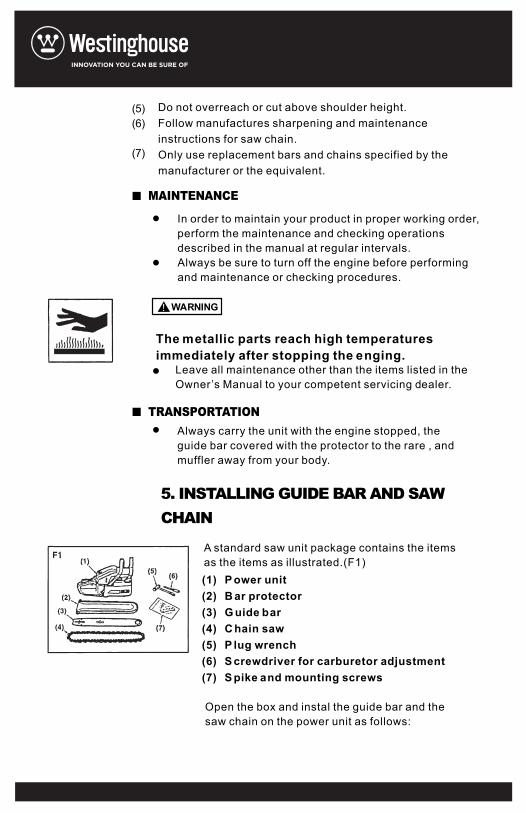
A standard saw unit package contains the itemsas the items as illustrated.(F1)
Open the box and instal the guide bar and thesaw chain on the power unit as follows:
(1) P ower unit(2) B ar protector(3) G uide bar(4) C hain saw(5) P lug wrench(6) S crewdriver for carburetor adjustment(7) S pike and mounting screws
(5)(6)
(7)
The metallic parts reach high temperaturesimmediately after stopping the enging.
MAINTENANCE
TRANSPORTATION
5. INSTALLING GUIDE BAR AND SAWCHAIN
WARNING!
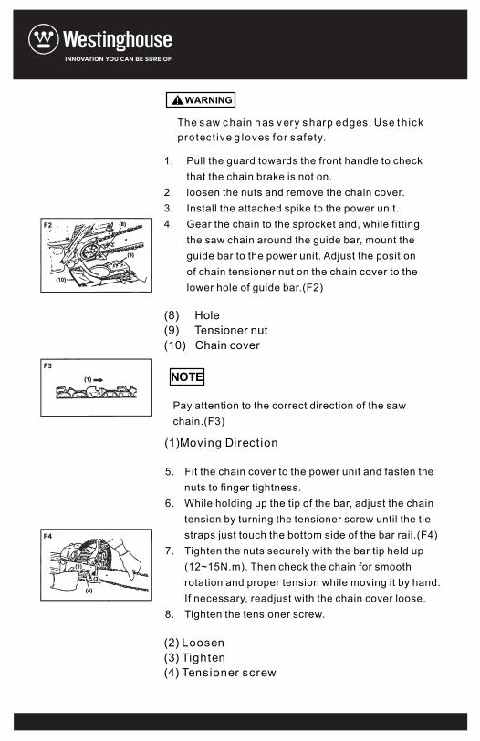
The s aw c hain h as v ery s harp edges. Use t h ickprotect ive g loves f or s afety.
Pull the guard towards the front handle to checkthat the chain brake is not on.loosen the nuts and remove the chain cover.Install the attached spike to the power unit.Gear the chain to the sprocket and, while fittingthe saw chain around the guide bar, mount theguide bar to the power unit. Adjust the positionof chain tensioner nut on the chain cover to thelower hole of guide bar.(F2)
Pay attention to the correct direction of the sawchain.(F3)
Fit the chain cover to the power unit and fasten thenuts to finger tightness.While holding up the tip of the bar, adjust the chaintension by turning the tensioner screw until the tiestraps just touch the bottom side of the bar rail.(F4)Tighten the nuts securely with the bar tip held up(12~15N.m). Then check the chain for smoothrotation and proper tension while moving it by hand.If necessary, readjust with the chain cover loose.Tighten the tensioner screw.
(8) Hole(9) Tensioner nut(10) Chain cover
(1)Moving Direct ion
(2) Loosen(3) Tighten(4) Tensioner screw
1.
2.3.4.
5.
6.
7.
8.
NOTE
WARNING!
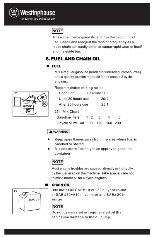
A new chain will expand its length is the beginning ofuse. Check and readjust the tension frequently as a loose chain can easily derail or cause rapid wear of itselfand the guide bar.
Mix a regular gasoline (leaded or unleaded, alcohol-free)and a quality-proven motor oil for air cooled 2 cycleengines.
Keep open flames away from the area where fuel ishandled or stored.Mix and store fuel only in an approved gasolinecontainer.
Most engine troubles are caused, directly or indirectly,by the fuel used on the machine. Take special care notto mix a motor oil for 4 cycle engines.
Use motor oi l SAE# 10 W ~30 al l year roundor SAE #30~#40 in summer and SAE# 20 inwinter.
Do not use wasted or regenerated oi l thatcan cause damage to the oi l pump.
6. FUEL AND CHAIN OIL
CHAIN OIL
FUEL
Recommended mixing ratio:Condition Gasoline : OilUp to 20 hours use 20:1After 20 hours use 25:1
Gasoline liters 1 2 3 4 52-cycle oil ml. 40 80 120 160 200
25:1 Mix Chart
NOTE
NOTE
NOTE
WARNING!
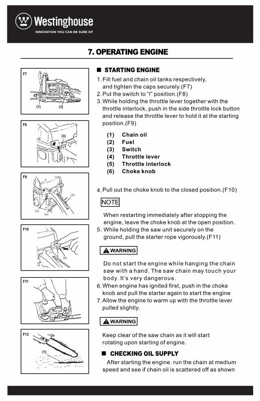
Fill fuel and chain oil tanks respectively,and tighten the caps securely.(F7)Put the switch to “l” position.(F8)While holding the throttle lever together with thethrottle interlock, push in the side throttle lock buttonand release the throttle lever to hold it at the startingposition.(F9)
(1) Chain oil(2) Fuel(3) Switch(4) Throttle lever(5) Throttle interlock(6) Choke knob
Pull out the choke knob to the closed position.(F10)
When restarting immediately after stopping theengine, leave the choke knob at the open position.While holding the saw unit securely on theground, pull the starter rope vigorously.(F11)
Do not start the engine while hanging the chainsaw with a hand. The saw chain may touch yourbody. It ’s very dangerous.When engine has ignited first, push in the chokeknob and pull the starter again to start the engineAllow the engine to warm up with the throttle leverpulled slightly.
Keep clear of the saw chain as it will startrotating upon starting of engine.
After starting the engine. run the chain at mediumspeed and see if chain oil is scattered off as shown
7. OPERATING ENGINE
STARTING ENGINE
CHECKING OIL SUPPLY
1.
2.3.
4.
5.
6.
7.
F7
F8
F9
F10
F11
F12
NOTE(3)
(4)
(5)
(6)
WARNING!
WARNING!
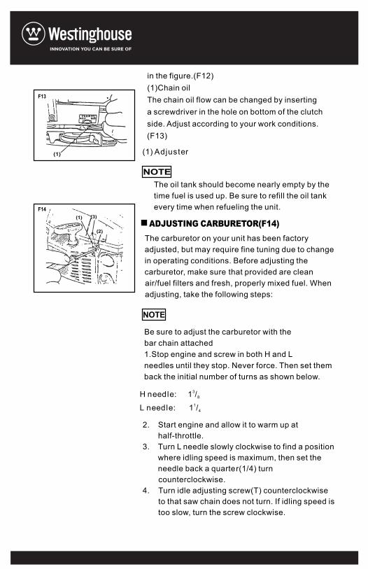
in the figure.(F12)(1)Chain oilThe chain oil flow can be changed by insertinga screwdriver in the hole on bottom of the clutchside. Adjust according to your work conditions.(F13)
The oil tank should become nearly empty by thetime fuel is used up. Be sure to refill the oil tankevery time when refueling the unit.
The carburetor on your unit has been factoryadjusted, but may require fine tuning due to changein operating conditions. Before adjusting thecarburetor, make sure that provided are cleanair/fuel filters and fresh, properly mixed fuel. Whenadjusting, take the following steps:
Be sure to adjust the carburetor with thebar chain attached1.Stop engine and screw in both H and Lneedles until they stop. Never force. Then set themback the initial number of turns as shown below.
Start engine and allow it to warm up athalf-throttle.Turn L needle slowly clockwise to find a positionwhere idling speed is maximum, then set theneedle back a quarter(1/4) turncounterclockwise.Turn idle adjusting screw(T) counterclockwiseto that saw chain does not turn. If idling speed istoo slow, turn the screw clockwise.
ADJUSTING CARBURETOR(F14)
(1) Adjuster
3H needle: 1 /8
1L needle: 1 /4
2.
3.
4.
NOTE
NOTE
F13
F14
5. Make a test cut and adjust the H needle for bestcutting power, not for maximum speed.
(1) L needle(2) H needle(3) Idle adjust ing screw
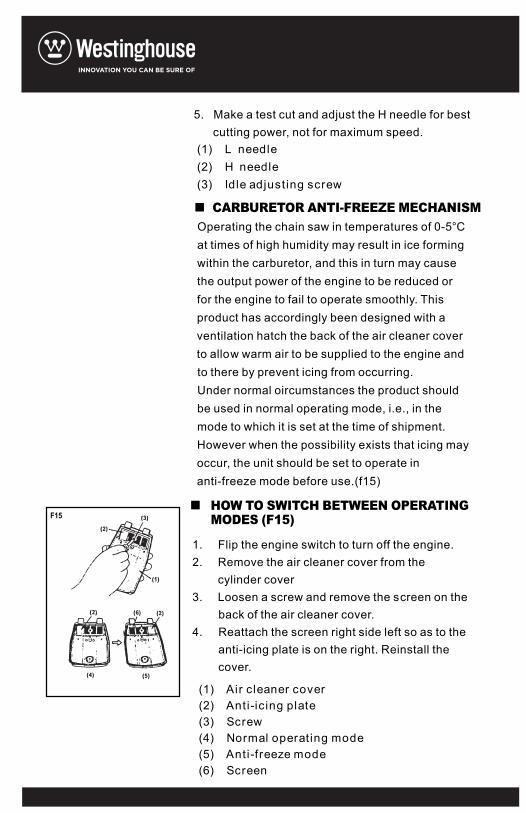
Operating the chain saw in temperatures of 0-5°Cat times of high humidity may result in ice formingwithin the carburetor, and this in turn may causethe output power of the engine to be reduced orfor the engine to fail to operate smoothly. Thisproduct has accordingly been designed with aventilation hatch the back of the air cleaner coverto allow warm air to be supplied to the engine andto there by prevent icing from occurring.Under normal oircumstances the product shouldbe used in normal operating mode, i.e., in themode to which it is set at the time of shipment.However when the possibility exists that icing mayoccur, the unit should be set to operate inanti-freeze mode before use.(f15)
Flip the engine switch to turn off the engine.Remove the air cleaner cover from thecylinder coverLoosen a screw and remove the screen on theback of the air cleaner cover.Reattach the screen right side left so as to theanti-icing plate is on the right. Reinstall thecover.
(1) Air cleaner cover(2) Anti-ic ing plate(3) Screw(4) Normal operating mode(5) Anti-freeze mode(6) Screen
CARBURETOR ANTI-FREEZE MECHANISM
HOW TO SWITCH BETWEEN OPERATINGMODES (F15)
1.2.
3.
4.
F15
Continuing to use the product in anti- freezemode even when temperatures have risenand returned to normal may result in theengine fai l ing to start properly or in theengine fai l ing to operate at i ts normal speed,and for this reason you should always besure to return the unit to normal operatingmode if there is no danger of icing occurr ing.
When using the saw with the anti-freeze mode,frequently check the screen and keep it clean ofsaw dust.
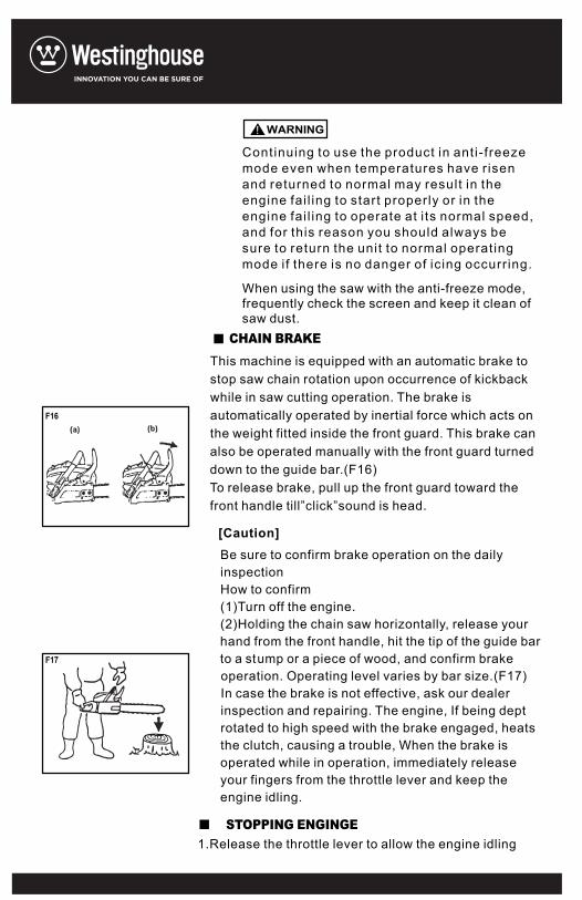
This machine is equipped with an automatic brake tostop saw chain rotation upon occurrence of kickbackwhile in saw cutting operation. The brake isautomatically operated by inertial force which acts onthe weight fitted inside the front guard. This brake canalso be operated manually with the front guard turneddown to the guide bar.(F16)To release brake, pull up the front guard toward thefront handle till”click”sound is head.
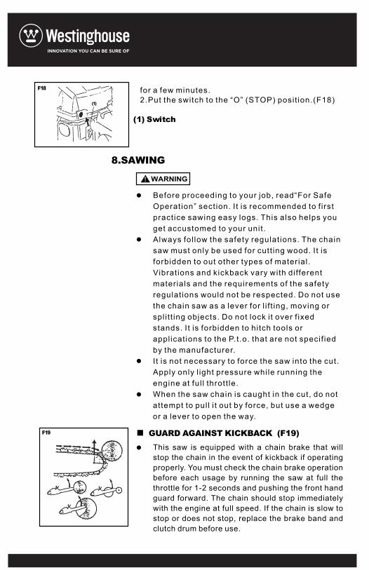
Be sure to confirm brake operation on the dailyinspectionHow to confirm(1)Turn off the engine.(2)Holding the chain saw horizontally, release yourhand from the front handle, hit the tip of the guide barto a stump or a piece of wood, and confirm brakeoperation. Operating level varies by bar size.(F17)In case the brake is not effective, ask our dealerinspection and repairing. The engine, If being deptrotated to high speed with the brake engaged, heatsthe clutch, causing a trouble, When the brake isoperated while in operation, immediately releaseyour fingers from the throttle lever and keep theengine idling.
1.Release the throttle lever to allow the engine idling
CHAIN BRAKE
STOPPING ENGINGE
[Caution]
F16
F17
WARNING!
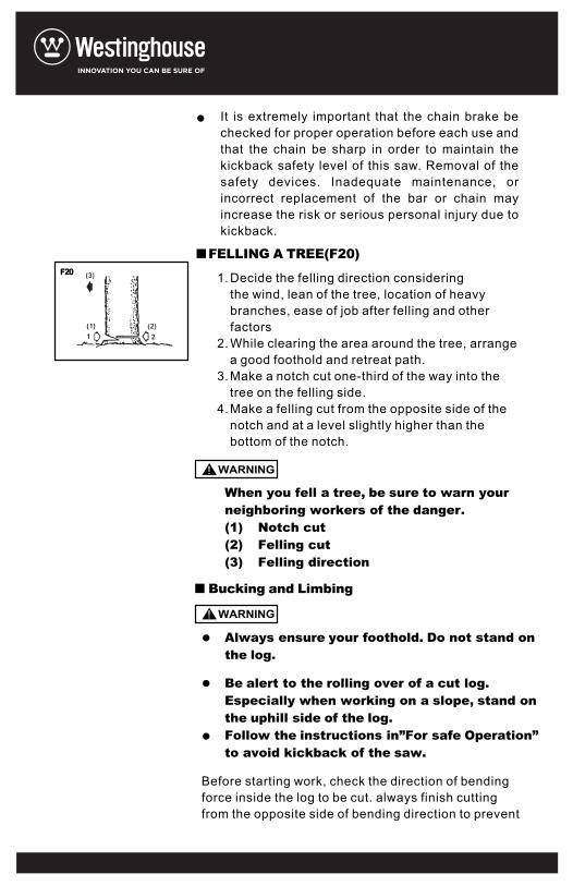
for a few minutes.2.Put the switch to the “O” (STOP) posit ion.(F18)
(1) Switch
Before proceeding to your job, readOperation” section. It is recommended to f irstpract ice sawing easy logs. This also helps youget accustomed to your unit .Always fol low the safety regulat ions. The chainsaw must only be used for cutt ing wood. It isforbidden to out other types of material.Vibrat ions and kickback vary with differentmaterials and the requirements of the safetyregulat ions would not be respected. Do not usethe chain saw as a lever for l i f t ing, moving orspl i t t ing objects. Do not lock it over f ixedstands. It is forbidden to hitch tools orappl icat ions to the P.t.o. that are not specif iedby the manufacturer.I t is not necessary to force the saw into the cut.Apply only l ight pressure while running theengine at ful l thrott le.When the saw chain is caught in the cut, do notattempt to pul l i t out by force, but use a wedgeor a lever to open the way.
“For Safe
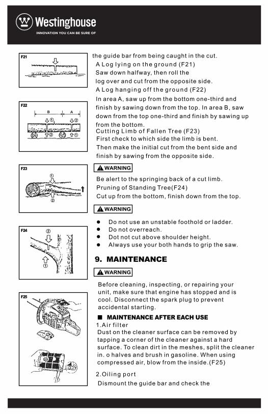
This saw is equipped with a chain brake that willstop the chain in the event of kickback if operatingproperly. You must check the chain brake operationbefore each usage by running the saw at full thethrottle for 1-2 seconds and pushing the front handguard forward. The chain should stop immediatelywith the engine at full speed. If the chain is slow tostop or does not stop, replace the brake band andclutch drum before use.
GUARD AGAINST KICKBACK (F19)
8.SAWING
F19
F18
(1)
WARNING!
It is extremely important that the chain brake bechecked for proper operation before each use andthat the chain be sharp in order to maintain thekickback safety level of this saw. Removal of thesafety devices. Inadequate maintenance, orincorrect replacement of the bar or chain mayincrease the risk or serious personal injury due tokickback.
Decide the felling direction consideringthe wind, lean of the tree, location of heavybranches, ease of job after felling and otherfactorsWhile clearing the area around the tree, arrangea good foothold and retreat path.Make a notch cut one-third of the way into thetree on the felling side.Make a felling cut from the opposite side of thenotch and at a level slightly higher than thebottom of the notch.
Before starting work, check the direction of bendingforce inside the log to be cut. always finish cuttingfrom the opposite side of bending direction to prevent
FELLING A TREE(F20)
1.
2.
3.
4.
Bucking and Limbing
F20
Be alert to the rolling over of a cut log.Especially when working on a slope, stand onthe uphill side of the log.Follow the instructions in”For safe Operation”to avoid kickback of the saw.
Always ensure your foothold. Do not stand onthe log.
When you fell a tree, be sure to warn yourneighboring workers of the danger.(1) Notch cut(2) Felling cut(3) Felling direction
WARNING!
WARNING!
the guide bar from being caught in the cut.
Saw down halfway, then roll thelog over and cut from the opposite side.
In area A, saw up from the bottom one-third andfinish by sawing down from the top. In area B, sawdown from the top one-third and finish by sawing upfrom the bottom.
First check to which side the limb is bent.Then make the init ial cut from the bent side andfinish by sawing from the opposite side.
Be alert to the springing back of a cut l imb.Pruning of Standing Tree(F24)Cut up from the bottom, finish down from the top.
Do not use an unstable foothold or ladder.Do not overreach.Dot not cut above shoulder height.Always use your both hands to grip the saw.
Before cleaning, inspecting, or repairing yourunit, make sure that engine has stopped and iscool. Disconnect the spark plug to preventaccidental start ing.
Dust on the cleaner surface can be removed bytapping a corner of the cleaner against a hardsurface. To clean dirt in the meshes, spli t the cleanerin. o halves and brush in gasoline. When usingcompressed air, blow from the inside.(F25)
Dismount the guide bar and check the
A L o g l y i n g o n t h e g r o u n d (F21)
A L o g h an g i n g o f f t h e g r o u n d (F22)
Cu t t i n g L i m b o f Fal l en Tr ee (F23)
1.A i r f i l t er
2.Oi l i n g p o r t
MAINTENANCE AFTER EACH USE
9. MAINTENANCE
F21
F22
F23
F24
F25
WARNING!
WARNING!
WARNING!
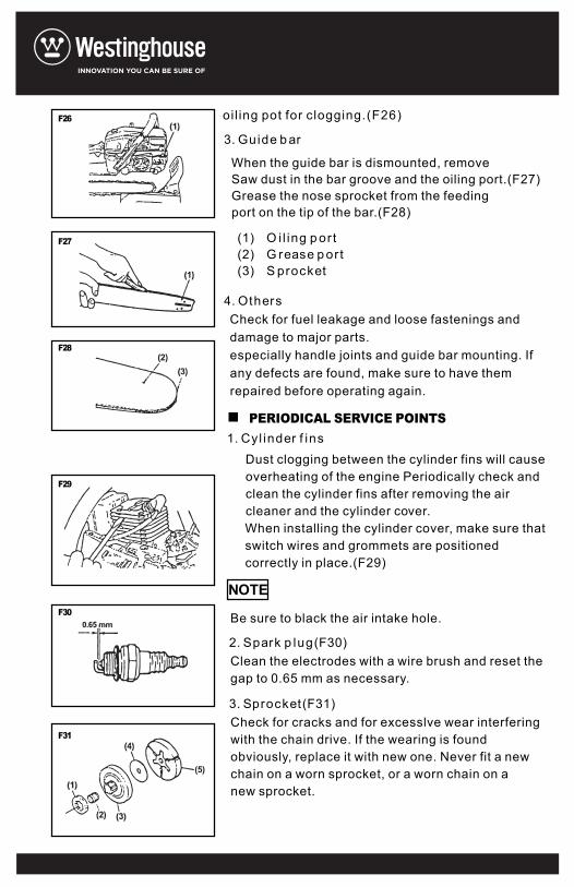
oil ing pot for clogging.(F26)
When the guide bar is dismounted, removeSaw dust in the bar groove and the oiling port.(F27)Grease the nose sprocket from the feedingport on the tip of the bar.(F28)
Check for fuel leakage and loose fastenings anddamage to major parts.especially handle joints and guide bar mounting. Ifany defects are found, make sure to have themrepaired before operating again.
Dust clogging between the cylinder fins will causeoverheating of the engine Periodically check andclean the cylinder fins after removing the aircleaner and the cylinder cover.When installing the cylinder cover, make sure thatswitch wires and grommets are positionedcorrectly in place.(F29)
Be sure to black the air intake hole.
Clean the electrodes with a wire brush and reset thegap to 0.65 mm as necessary.
Check for cracks and for excesslve wear interferingwith the chain drive. If the wearing is foundobviously, replace it with new one. Never fit a newchain on a worn sprocket, or a worn chain on a new sprocket.
(1) O i l ing p or t(2) G rease p or t(3) S procket
3. Guide b ar
4. Others
1. Cyl inder f ins
2. Spark p lug(F30)
3. Sprocket(F31)
PERIODICAL SERVICE POINTS
NOTE
F26
F27
F28
F29
F30
F31
WARNING!
WARNING!
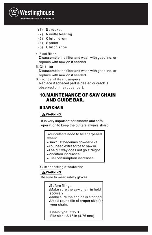
(2) N eedle b ear ing(3) C lutch d rum(4) S pacer(5) C lutch s hoe
4. Fuel f i l ter
5. Oi l f i l ter
6. Front and Rear d ampers
Disassemble the filter and wash with gasoline, orreplace with new on if needed.
Disassemble the filter and wash with gasoline, orreplace with new on if needed.
Replace if adhered part is peeled or crack isobserved on the rubber part.
It is very important for smooth and safeoperation to keep the cutters always sharp.
Your cutters need to be sharpenedwhen:Sawdust becomes powder-like.You need extra force to saw in.The cut way does not go straightVibration increasesFuel consumption increases
Be sure to wear safety gloves.
Make sure the saw chain in held sccurelyMake sure the engine is stoppedUse a round file of proper size foryour chain.
Chain type: 21VBFile size: 3/16 in (4.76 mm)
Before filing:
SAW CHAIN
10.MAINTENANCE OF SAW CHAINAND GUIDE BAR.
Cutter s et t ing s tandards:
(1) S procket
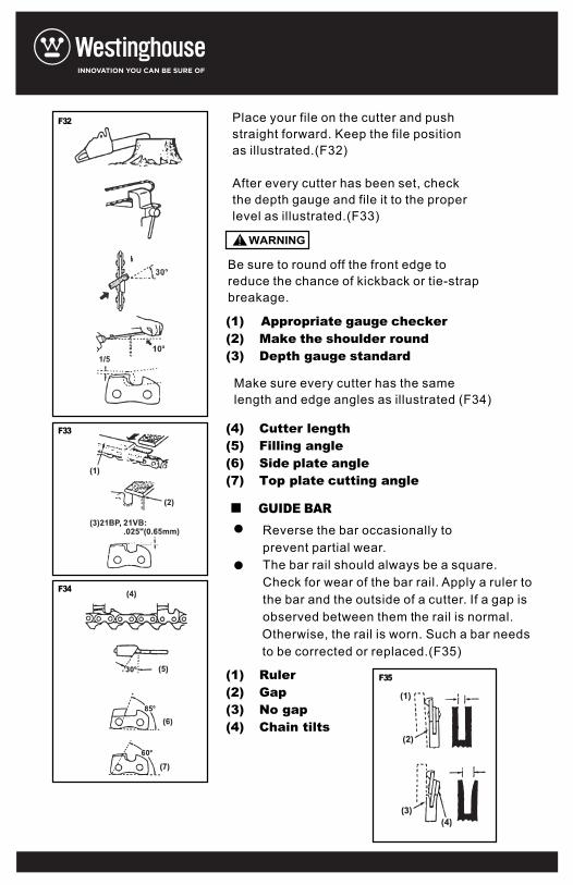
Place your file on the cutter and pushstraight forward. Keep the file positionas illustrated.(F32)
After every cutter has been set, checkthe depth gauge and file it to the properlevel as illustrated.(F33)
Be sure to round off the front edge toreduce the chance of kickback or tie-strapbreakage.
Make sure every cutter has the samelength and edge angles as illustrated (F34)
Reverse the bar occasionally toprevent partial wear.The bar rail should always be a square.Check for wear of the bar rail. Apply a ruler tothe bar and the outside of a cutter. If a gap isobserved between them the rail is normal.Otherwise, the rail is worn. Such a bar needsto be corrected or replaced.(F35)
GUIDE BAR
F32
F33
F34
F35(1) Ruler(2) Gap(3) No gap(4) Chain tilts
(4) Cutter length(5) Filling angle(6) Side plate angle(7) Top plate cutting angle
(1) Appropriate gauge checker(2) Make the shoulder round(3) Depth gauge standard
WARNING!

11. SPECIFICATIONS
1
2
3
4
5
6
7
8
9
10
11
12
13
14
15
16
17
4600
7.5(kg)
410 X 235 X 265(mm)
Mixture (Gasoline 25: Two-cycleoil 1)
550(ml)
Motor oil SAE#10W-30
260(ml)3
46(cm3)
1.6kw/7500rpm
10000rpm
2800rpm
7T X 0.325
0.325(in)
0.058(in)
Sprocket nose
16 18 20(in)
Automatic pump with adjuster
Chain saw Model
Mass (without guide bar and chain)
Dimensions (without guide bar and chain)
Fuel
Fuel tank capacity
Chain oil
Oil tank capacity
Engine displacement
Maximum engine power
Maximum engine speed with cutting
attachment
Maximum Engine speed at idling
Sprocket
Saw chain pitch
Saw chain gauge
Guide bar type
Guide bar size
Oil feeding system
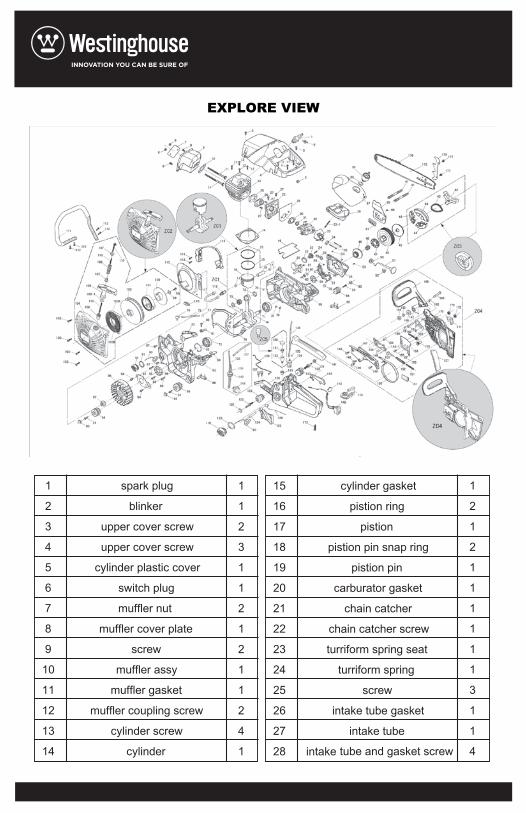
EXPLORE VIEW
1
2
3
4
5
6
7
8
9
10
11
12
13
14
spark plug
blinker
upper cover screw
upper cover screw
cylinder plastic cover
switch plug
muffler nut
muffler cover plate
screw
muffler assy
muffler gasket
muffler coupling screw
cylinder screw
cylinder
1
1
2
3
1
1
2
1
2
1
1
2
4
1
15
16
17
18
19
20
21
22
23
24
25
26
27
28
cylinder gasket
pistion ring
pistion
pistion pin snap ring
pistion pin
carburator gasket
chain catcher
chain catcher screw
turriform spring seat
turriform spring
screw
intake tube gasket
intake tube
intake tube and gasket screw
1
2
1
2
1
1
1
1
1
1
3
1
1
4

29
30
31
32
33
34
35
36
37
38
39
40
41
43
44
45
46
47
48
49
50
51
52
53
54
55
56
57
intake tube bracket
intake tube bracket gasket
intake flange
retaining ring
carburator assy
intake angle pipe
intake angle pipe stud
intake angle pipe shock absorption
carburator screw
air filter
air filter top cover
lock nut gasket
air filter lock nut
stud
body frame
clutch pullback spring
shoe block
clutch washer
clutch drum
chain wheel
clutch needle bearing
endless screw
choke knob sleeve
choker rod
choker rod-shock absorption
oil bump cover screw
oil bump cover
oil outlet pipe
1
1
1
1
1
1
1
1
2
1
1
1
1
2
1
1
3
1
1
1
1
1
1
1
1
3
1
1
58
59
60
61
62
63
64
65
66
67
68
69
70
71
72
73
74
75
76
77
78
79
80
81
oil pump screw
oil pump assy
oil pump dustproof filter cotton
small seal oil
breath nipple snap spring
filter cotton
breath nipple
small plug pad
rubber cushioning pad
oil outlet cover plate
oil outlet cover plate screw
chain guiding block
right rubber cushioning pad
right crank case
pin
bearing ball
needle bearing circlip
small end of connecting rod-ball bearing
crankshaft with connecting rod assembly
woodruff key
crank case gasket
negative pressure pipe-snap ring
negative pressure pipe
negative pressure nozzle
2
1
1
1
1
1
1
3
3
1
1
2
1
1
3
2
2
1
1
1
1
1
1
1

82
83
84
85
86
87
88
89
90
91
92
93
94
95
96
97
99
100
101
102
103
104
105
106
107
108
109
stop switch wire clamp
stop switch wire pressplate
idling speed regulating sleeve
circlip for hole
HL sleeve
left crank case
left rubber cushioning pad
screw
screw
big oil seal
suspension loop
oil cap gasket
oil cap
oil seal plate
oil seal plate screw
flywheel assy
flywheel nut
starter screw
starter screw gasket
pulley starter
energy stored spring
starter connecting pulley
starter spring cover
starter spring
starter housing
starter housing screw
rope sleeve
1
1
1
1
1
1
1
2
3
1
2
1
1
1
2
1
1
1
1
1
1
1
1
1
1
4
1
110
111
112
113
114
115
116
117
118
119
120
121
122
123
124
125
126
127
128
129
130
131
132
133
134
135
136
137
handle inner ring
recoil spring
starter handle
starter handle gasket
rope
handle
handle screw
ignition screw
ignition assy
air deflector
LH sleeve
oil intake pipe
oil filter
fuel cap
fuel cap gasket
big dust proof cover
nut
long cushioning rubber pad
trigger pin
trigger
trigger spring
double cushioning screw
fuel tank
throttle rod
balance cover
balance valve
balance housing
balance support
2
1
1
1
1
1
4
2
1
1
1
1
1
1
1
2
2
2
1
1
1
1
1
1
1
1
1
1

138
139
140
141
142
143
144
145
146
147
148
149
150
151
152
153
154
155
156
157
158
159
160
161
162
163
164
165
fuel oil filter assy
fuel oil pipe snap ring
fuel oil pipe
oil inlet tube
fuel pipe
oil return pipe
oil pump support
rear handle
lever trigger
decorative cover
primer pump
switch
brake spring cover plate screw
brake spring cover plate
main lever
auxiliary lever
straight pin
brake strap
brake ancillary spring
brake spring
brake lever
chain brake lever pin bush
tensioning cover plate screw
tensioning cover plate
oil baffle
tensioning driving gear
tensioning following gear
tensioning pin
1
1
1
1
1
1
1
1
1
1
1
1
4
1
1
1
3
1
1
1
1
1
2
1
1
1
1
1
166
167
168
169
170
171
172
173
174
175
176
177
178
179
180
181
182
183
184
185
186
187
188
spacer pin
split washer
spacer plate
rubber gasket
split washer
gasket
brake torsional spring
chain brake lever
chain brake lever pin
right side cover
rubber block
flange nut
rear handle screw
dustproof rubber plate
chinese bar
chain assy
screw plate screw
spike
crank shaft with connecting rod and piston assy
starter assy
clutch assy
brake assy
balance assy
1
2
1
1
1
1
1
1
1
1
1
2
1
1
1
1
2
1
11
1
1
1