Manual de Montaje y Mantenimiento 2014 Inglés
10
TTV • C/ Severo Ochoa, 11 • P.I. Nuestra Señora de Butarque • 28914 Leganés • Madrid • Tel: 91 685 7365 • Fax: 91 680 0660 • [email protected] • www.ttv.es 11-06-2014 1 MANUAL OF WORKING INSTRUCTIONS, ASSEMBLING, MAINTENANCE AND STORAGE BUTTERFLY VALVES
Transcript of Manual de Montaje y Mantenimiento 2014 Inglés
TTV • C/ Severo Ochoa, 11 • P.I. Nuestra Señora de Butarque • 28914 Leganés • Madrid • Tel: 91 685 7365 • Fax: 91 680 0660 • [email protected] • www.ttv.es
11-06-2014 1
MANUAL OF WORKING INSTRUCTIONS, ASSEMBLING, MAINTENANCE AND STORAGE
BUTTERFLY VALVES
TTV • C/ Severo Ochoa, 11 • P.I. Nuestra Señora de Butarque • 28914 Leganés • Madrid • Tel: 91 685 7365 • Fax: 91 680 0660 • [email protected] • www.ttv.es
11-06-2014 2
INSTRUCTIONS MANUAL For BUTTERFLY VALVES Wafer, Lug and Flange type Range : From DN32 to DN1400 1) GENERAL 2) WARNINGS 3) WORKING CONDITIONS AND TECHNICAL INFORMATION 4) OPERATION AND WAY OF ROTATION 5) INSTALLATION INSTRUCTIONS 6) MAINTENANCE INSTRUCTIONS 7) STORAGE INSTRUCTIONS 1) GENERAL This instructions manual contains important information concerning the installation, operation, maintenance and storage of TTV butterfly valves. Please read carefully these instructions and keep them for future occasions. It is important that only well- informed and qualified people operate the valves. 2) WARNINGS - Make sure that the valves are used within the limits established in the technical specifications. - Using the valves above the temperature limits can damage the internal and the external elements. - Using the valves above the pressure limits can damage the internal and the external elements. - Using the valve in corrosive environments, without the proper protection, can damage the internal and the external elements. - Do not try to dismantle any part of the valve while it is installed in the pipe, and do not do it neither if there is fluid inside. - Purge the whole installation, being sure there is no air inside when the fluid is liquid. - Do not dismantle the shaft while the valve is installed in the pipe; the disc would be carried away through the pipe due to the pressure of the fluid. - Make sure which is the rotation way of the valve when mounting any type of actuation (there are stops clearly marked and opening / closing icons of the disc at 90º). - When the valves are to be installed at the pipeline end, it is necessary to install counter flanges downstream with their corresponding bolting. - It is necessary to carry out an “open/close” test at least once a year. - TTV valves are delivered with seat placed inside with the valonas outward, so they do not need to use single assembly joint. 3) WORKING CONDITIONS AND TECHNICAL INFORMATION - Fluids : These valves are delivered for fluid as well as for gas services. It is the customer´s responsibility or the Engineer which leads the project, the decision of choosing the most apropriate materials for the required service, as well as the evaluation of the installation risks.

TTV • C/ Severo Ochoa, 11 • P.I. Nuestra Señora de Butarque • 28914 Leganés • Madrid • Tel: 91 685 7365 • Fax: 91 680 0660 • [email protected] • www.ttv.es
11-06-2014 3
- Working pressure: These valves are delivered for a working pressure of 20 bar maximum. - Working temperature: The standard valves delivered are between the range of temperature: from -10ºC to + 90ºC. - Ambient temperature: The standard valves delivered are designed to work within the range: from –10ºC to +80ºC. - Operation time: These valves are delivered with a connecting flange as per ISO 5211. The time of operation will vary depending on the type of operation mounted.. - Travel: The standard construction has a rotating travel from 0 to 90 degrees and from 90 to 0 degrees. - Lubrication: TTV butterfly are not lubricated. - Construction : Movement transmision through the splined shaft and disc, designed for inside and outside installations. - Protection and resistance against corrosion: Every standard valve is delivered with protection against corrosion for normal environmental conditions. For this reason the valves undergo a process of Rilsanization (RILSAN Polyamide 11). Before installing the valves in agresive enviromental conditions, make sure you have chosen the appropriate protecction. -The proper maintenance of valves involves cleaning of surface of valves. This procedure should be carried out softly and with neutral soap. This is advisable to carry out an “open/close” trial as well. - Valves labelling and designation : The type of valve, diameter, pressure design, maximun working pressure, lining, reference... are stated in the valve designation. TTV valves are delivered with labels containing the following information: TTV anagram, type, model, type of operation, pressure design, maximum pressure, lining, manufacturing order, date and CE marking. 4) OPERATION AND WAY OF ROTATION In order to close the valve, the shaft is moved clockwise; to open the valve, the shaft is moved in the opposite direction. The valve is regulated by means of the operation devices, which are the following: a) Manual actuator with lever The regulation is carried out by means of the notch flange and the lever´s latch. For this purpose, the latch is clutched from the flange and it is turned in the appropriate direction to open or to close the valve. Then the latch is clutched again in the flange in the desired position.
TTV • C/ Severo Ochoa, 11 • P.I. Nuestra Señora de Butarque • 28914 Leganés • Madrid • Tel: 91 685 7365 • Fax: 91 680 0660 • [email protected] • www.ttv.es
11-06-2014 4
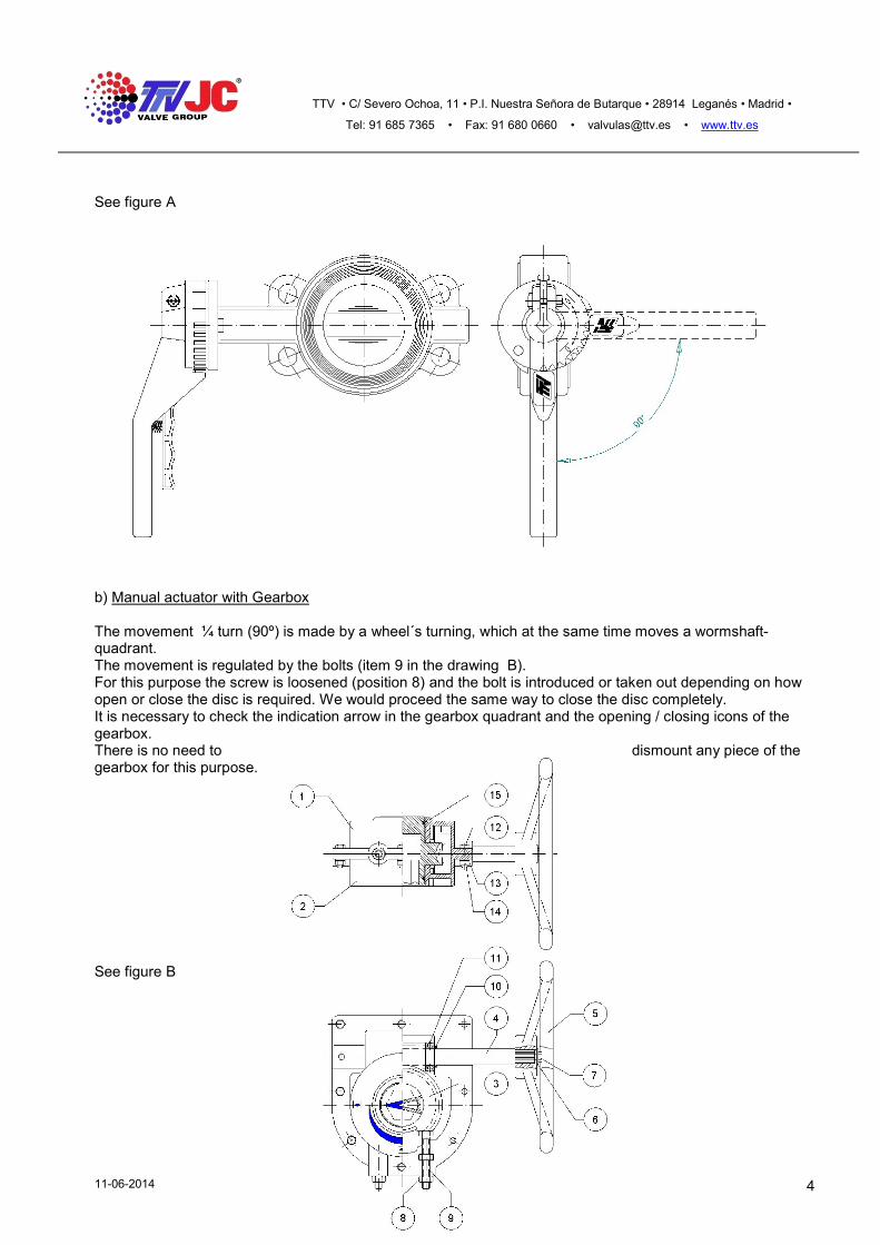
See figure A
b) Manual actuator with Gearbox The movement ¼ turn (90º) is made by a wheel´s turning, which at the same time moves a wormshaft-quadrant. The movement is regulated by the bolts (item 9 in the drawing B). For this purpose the screw is loosened (position 8) and the bolt is introduced or taken out depending on how open or close the disc is required. We would proceed the same way to close the disc completely. It is necessary to check the indication arrow in the gearbox quadrant and the opening / closing icons of the gearbox. There is no need to dismount any piece of the gearbox for this purpose.
See figure B
TTV • C/ Severo Ochoa, 11 • P.I. Nuestra Señora de Butarque • 28914 Leganés • Madrid • Tel: 91 685 7365 • Fax: 91 680 0660 • [email protected] • www.ttv.es
11-06-2014 5
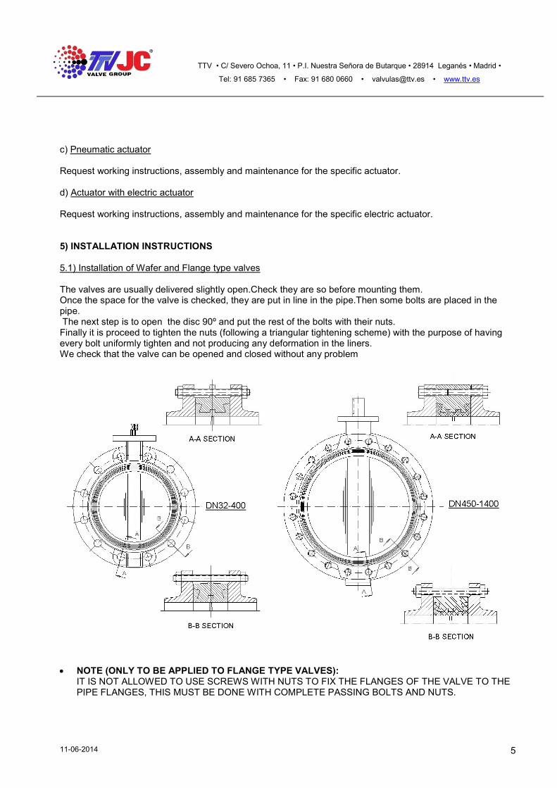
c) Pneumatic actuator Request working instructions, assembly and maintenance for the specific actuator. d) Actuator with electric actuator Request working instructions, assembly and maintenance for the specific electric actuator. 5) INSTALLATION INSTRUCTIONS 5.1) Installation of Wafer and Flange type valves The valves are usually delivered slightly open.Check they are so before mounting them. Once the space for the valve is checked, they are put in line in the pipe.Then some bolts are placed in the pipe. The next step is to open the disc 90º and put the rest of the bolts with their nuts. Finally it is proceed to tighten the nuts (following a triangular tightening scheme) with the purpose of having every bolt uniformly tighten and not producing any deformation in the liners. We check that the valve can be opened and closed without any problem
NOTE (ONLY TO BE APPLIED TO FLANGE TYPE VALVES):
IT IS NOT ALLOWED TO USE SCREWS WITH NUTS TO FIX THE FLANGES OF THE VALVE TO THE PIPE FLANGES, THIS MUST BE DONE WITH COMPLETE PASSING BOLTS AND NUTS.

TTV • C/ Severo Ochoa, 11 • P.I. Nuestra Señora de Butarque • 28914 Leganés • Madrid • Tel: 91 685 7365 • Fax: 91 680 0660 • [email protected] • www.ttv.es
11-06-2014 6
5.2) Installation of LUG type valve It follows the same procedure detailed for the other type of valves. These valves should be installed with screws, whose length allows the perfect tightening between the flanges and the pipe. These screws cannot be longer than allowed.
5.3) Mounting position TTV recomends that valves from DN450 onward are installed with the shaft in horizontal position. The valves are bidirectional. They can be installed on any side as it is not necessary to keep the fluids direction. WARNINGS FOR INSTALLATION - Before the valves are mounted, the liners have to be clean so as to guarantee the tightness of the valve. - There has to be room for the valve to prevent the liner from any damage when introducing the valve. - Be careful during its installation as the painting could be damaged. - Make sure, during the assembling of heavy valves, that the louse and slings meet the security standards. 6) MAINTENANCE INSTRUCTIONS TTV valves require little maintenance. However, due to the possibile high working requirements, the following maintenance actions should be conducted, if so required.

TTV • C/ Severo Ochoa, 11 • P.I. Nuestra Señora de Butarque • 28914 Leganés • Madrid • Tel: 91 685 7365 • Fax: 91 680 0660 • [email protected] • www.ttv.es
11-06-2014 7
1
2
3
4
5
6
7
8
9
9
The assembling and disassembling of the valve is only allowed to TTV staff or people specialised in this field. If these norms are not followed, then the guarantee will not have any validity. 6.1) Description and spare parts recommended. 6.1.1) Wafer, Lug and Flange type valves DN32 to DN200. Remove the actuator and top adjustable flange (Fig. 6) by loosening the screws (pos. 9) Using a screwdriver as a lever on the Circlip ( Fig. 7) start taking the shaft off. Take off the shaft completely and remove the disc (pos. 3 and 2). Using the same screwdriver as a lever on the liner, and taking care not to damage the surface, push the liner to the inside until its final removal. Replace the liner and O´Rings with new ones (pos. 4 and 5). By hand, without using any screwdriver, re-assemble the valve following inversely the above steps. Recommended spare parts: - Liner ( pos. 4) - O´Rings (pos. 5)

TTV • C/ Severo Ochoa, 11 • P.I. Nuestra Señora de Butarque • 28914 Leganés • Madrid • Tel: 91 685 7365 • Fax: 91 680 0660 • [email protected] • www.ttv.es
11-06-2014 8
1
2
3
4
5
6
7
8
6.1.2.) Wafer, Lug and flange Type valves from DN250 to DN400. Remove the actuator and take out the spring (pos. 8) and the Washer (pos. 7). Using a screwdriver as a lever on the Circlip (pos. 6) and proceed as described before. Recommended spare parts: - Liner (pos. 4)

TTV • C/ Severo Ochoa, 11 • P.I. Nuestra Señora de Butarque • 28914 Leganés • Madrid • Tel: 91 685 7365 • Fax: 91 680 0660 • [email protected] • www.ttv.es
11-06-2014 9
1
2
3
4
10
17
6
13
11
9
15
14
7
8
14
5
12
16
17
- O´Rings (pos. 5) 6.1.3) Wafer, Lug and Flnage valves from DN450 to DN1400. Remove the actuator and take out the screws (pos. 12 and 11), removing the caps (pos. 9 and 10). Remove the screw (pos. 13). Now the shaft is free and can be removed with an extractor, wich will be placed in the threaded part of the shaft. Then the disc is removed and the liner is taken out. For its installation, follow the opposite steps. Warning: Due to diameter, weight and installation complexity, this process should be done in TTV. Recommended spare parts: - Liner (pos. 4)
TTV • C/ Severo Ochoa, 11 • P.I. Nuestra Señora de Butarque • 28914 Leganés • Madrid • Tel: 91 685 7365 • Fax: 91 680 0660 • [email protected] • www.ttv.es
11-06-2014 10
- O´Rings (pos. 14, 15 and 16) 7) STORAGE INSTRUCTIONS The aim of these specifications is the appropiate preservation and storage ot TTV valves. - Temperature It would normally be no higher than 25 º C - Humidity it should be avoided. There must not be condensations. - Light They have to protected against sun light and ultraviolet rays. - Oxygen and Ozone Protected from air in circulation and against Ozone. - Deformation They must be stored avoiding any deformation - Contact with metals The liners´parts should not be in contact with copper or manganese. - Contact with liquids They must be kept away from dissolvents, grease, oil, acid… - Contact with dusty materials. They must be free from talcum powder, ceramic products … - Rotation of stored products The older ones have to be used first - Cleaning If it is necessary to clean the valves, do not use abrasive products, tricloroetiline, hydrocarbon …