MANUAL Ósmosis
143
MANUAL PEDAGÓGICO, TÉCNICO Y DE USO DEL EQUIPO TA-UO-100/DEL SISTEMA DE SEPARACIÓN POR MEMBRANA CON CARTUCHOS DE ÓSMOSIS INVERSA Y ULTRAFILTRACIÓN NO. DE SERIE: EH – 0910 - 185
description
Se trata de un manual del funcionamiento de un equipo de ósmosis inversa sencillo, que ayuda a conocer los principios de esta operación.
Transcript of MANUAL Ósmosis
MA
NU
AL P
ED
AG
ÓG
IC
O,
TÉC
NIC
O
Y D
E U
SO
DEL E
QU
IP
O
TA-UO-100/DEL
SISTEMA DE SEPARACIÓN POR
MEMBRANA CON CARTUCHOS DE
ÓSMOSIS INVERSA Y
ULTRAFILTRACIÓN
NO. DE SERIE: EH – 0910 - 185

TABLA DE CONTENIDOS
1. ASPECTOS TÉCNICOS Y DE INGENIERÍA
1.1 VISTA DEL EQUIPO…………………………4
1.2 ESPECIFICACIONES TÉCNICAS…………………………5
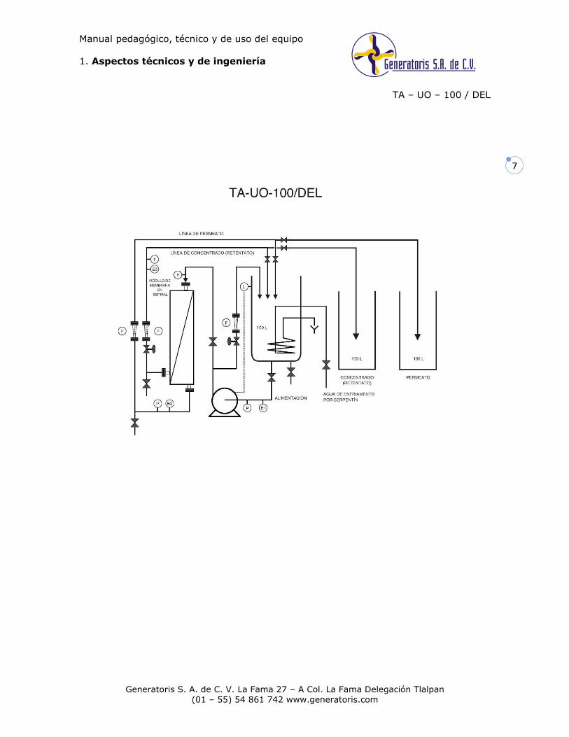
1.3 DIAGRAMA DE FLUJO DE PROCESO (DFP)…………………………7
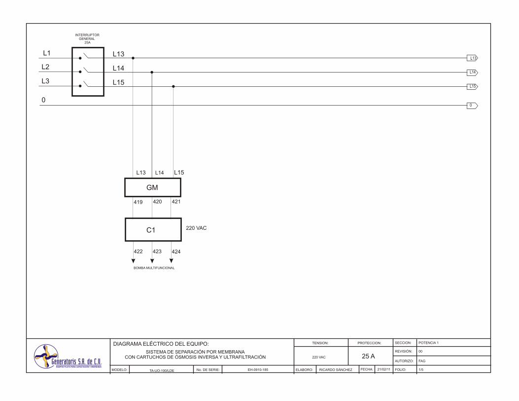
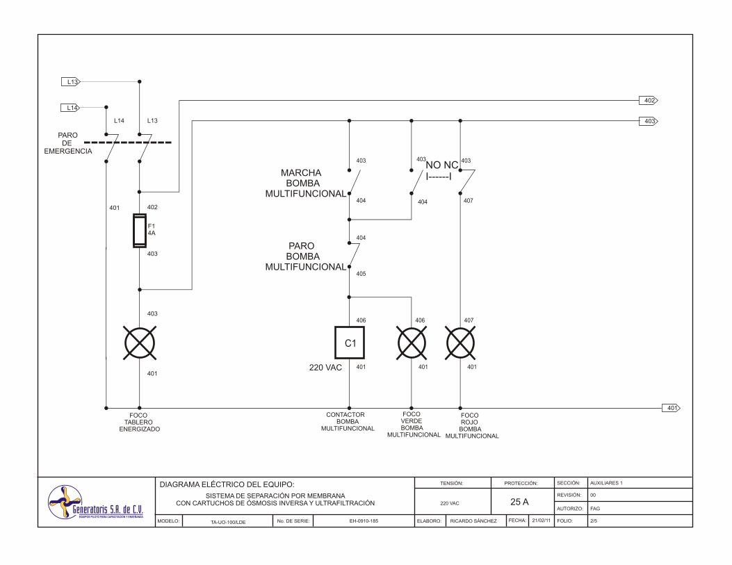
1.4 DIAGRAMA ELÉCTRICO………………………………………………………..8
2. ASPECTOS DE USO DEL EQUIPO
2.1 SEGURIDAD E HIGIENE…………………………14
2.2 OPERACIÓN DEL EQUIPO…………………………15
2.3 APLICACIONES EXPERIMENTALES…………………………16
2.4 MANTENIMIENTO Y LIMPIEZA…………………………16
3. ASPECTOS PEDAGÓGICOS
3.1 FUNDAMENTOS TEÓRICOS…………………………18
3.2 PRÁCTICAS PROPUESTAS…………………………23
4. DOCUMENTACIÓN
4.1 GARANTÍA SOBRE NUESTRO PRODUCTO…………………………33
4.2 ACTUALIZACIÓN…………………………34
4.3 CERTIFICADO DE CONFORMIDAD…………………………35
4.4 REPORTE DE PRUEBAS DE OPERACIÓN…………………………36
5. ANEXOS TÉCNICOS
5.1 RESOLUCIÓN DE LA PRÁCTICA 1: IDENTIFICACIÓN DE
COMPONENTES…………………………37
5.2 SENSOR DE CONDUCTIVIDAD
5.3 SONDA DE CONDUCTIVIDAD
5.4 INDICADOR DE TEMPERATURA
5.5 FUENTE DE PODER
5.6 BOMBA MULTIFUNCIONAL
Manual pedagógico, técnico y de uso del equipo
1. Aspectos técnicos y de ingeniería
TA – UO – 100 / DEL
Generatoris S. A. de C. V. La Fama 27 – A Col. La Fama Delegación Tlalpan (01 – 55) 54 861 742 www.generatoris.com
4
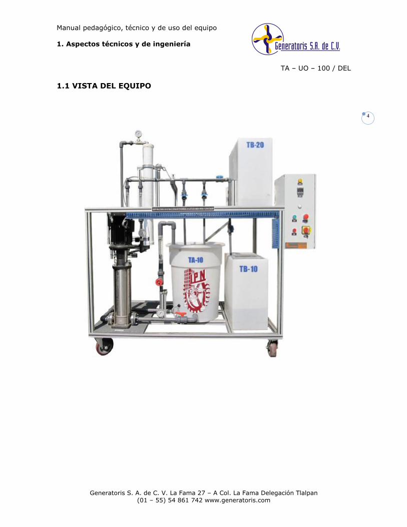
1.1 VISTA DEL EQUIPO
Manual pedagógico, técnico y de uso del equipo
1. Aspectos técnicos y de ingeniería
TA – UO – 100 / DEL
Generatoris S. A. de C. V. La Fama 27 – A Col. La Fama Delegación Tlalpan (01 – 55) 54 861 742 www.generatoris.com
5
1.2 ESPECIFICACIONES TÉCNICAS
Planta piloto montada sobre estructura en perfil de aluminio tipo industrial,
reforzado. Con unión estructural de todos los módulos y por medio de tubería.
Conjunto en una sola estructura.
Tanque de alimentación a procesos de membrana, capacidad de 100 litros.
Tanque de almacenamiento de concentrado, capacidad de 100 litros.
Tanque de almacenamiento de permeato, capacidad de 100 litros.
Membrana de osmosis inversa en espiral, para tratar agua de mar. Diámetro 4
pulgadas, longitud 40 pulgadas. Carcaza para membrana de osmosis inversa
Proceso de separación mediante membranas para recuperar el disolvente de
una solución salina.
Serpentín para enfriamiento en tanque de alimentación, fabricado en tubería de
cobre.
Rotámetro de flotador para medición de flujo de recirculación de 300 a 3000
l/h.
Rotámetro de flotador para la medición de flujo de concentrado de 100 a 1000
l/h.
Rotámetro de flotador para la medición de flujo de permeato de 60 a 500 l/h.
Bomba multietapas, de alta presión en acero inoxidable, con motor de 5 HP.
Válvula de regulación de flujo de recirculación de abastecimiento.
Válvula de regulación de flujo de salida de concentrado, fabricada en acero
inoxidable.
Válvula de descarga y toma de muestra del tanque de alimentación a procesos
de membrana.
Válvula de alimentación de agua de enfriamiento al serpentín, fabricada en
acero inoxidable.
Válvula de alimentación a membrana, fabricada en acero inoxidable, diámetro
de una pulgada.
Válvula de muestreo de concentrado.
Válvula de recirculación de concentrado.
Válvula de salida hacia tanque de concentrado.
Válvula de muestreo de permeato.
Válvula de recirculación de permeato.
Válvula de salida hacia tanque de permeato.
Válvula de descarga de tanque de concentrado.
Válvula de descarga de tanque de permeato.
Tubería para líneas de proceso de PVC cedula 80
Codos de 90 º fabricados en PVC cedula 80
TEE fabricada en PVC cedula 80
Tuerca unión fabricada en PVC cedula 80 para conjunción de secciones
Tubería de acero inoxidable 316
Tubing de acero inoxidable 316
Tuerca unión de acero inoxidable 316 para conjunción de secciones
Niples de acero inoxidable.
Codo 90 º acero inoxidable.
TEE acero inoxidable.
Manguera de alta presión con conectores.
Manual pedagógico, técnico y de uso del equipo
1. Aspectos técnicos y de ingeniería
TA – UO – 100 / DEL
Generatoris S. A. de C. V. La Fama 27 – A Col. La Fama Delegación Tlalpan (01 – 55) 54 861 742 www.generatoris.com
6
Sensor de conductividad colocado en línea de abastecimiento.
Indicador de conductividad (abastecimiento).
Sensor de conductividad en línea de permeato.
Sensores: (P) presión, (F) caudal, (T) temperatura, (E) conductividad.
Indicador de conductividad (permeato)
Sensor de conductividad en línea de concentrado / retentato.
Indicador de conductividad (concentrado / retentato).
Sensor de Temperatura PT 100 sobre la línea de concentrado.
Indicador de temperatura de concentrado.
Controlador de nivel, colocado en tanque de alimentación para protección de la
bomba.
Relevador de nivel.
Alimentación eléctrica 220V, 60 Hz.
Manómetro de acero inoxidable en la succión de la bomba.
Manómetro de acero inoxidable en la entrada de la membrana.
Manómetro de acero inoxidable en la salida de la membrana por la línea de
permeato.
GABINETE DE CONTROL
Gabinete de control tipo industrial NEMA 4X con elementos de protección
eléctricos y electrónicos.
Interruptor general
Indicador luminoso de tablero energizado.
Botón pulsador de arranque y paro de la bomba
Indicador luminoso con foco indicador de nivel adecuado.
Guardamotor y contactor para protección de la bomba
Portafusibles de protección.
Convertidor de voltaje 220 VAC / 24 VCD
Clemas de alimentación y tierra.
Componentes montados sobre riel.
Cableado interno montado sobre canaleta.
Identificación con números para todos los cables.
Botón tipo hongo de paro de emergencia.
DIMENSIONES APROXIMADAS
Largo: 1.90 metros
Profundidad: 1.10 metros
Altura: 2.30 metros
Manual pedagógico, técnico y de uso del equipo
1. Aspectos técnicos y de ingeniería
TA – UO – 100 / DEL
Generatoris S. A. de C. V. La Fama 27 – A Col. La Fama Delegación Tlalpan (01 – 55) 54 861 742 www.generatoris.com
7


Manual pedagógico, técnico y de uso del equipo
2. Aspectos de uso del equipo
TA – UO – 100 / DEL
Generatoris S. A. de C. V. La Fama 27 – A Col. La Fama Delegación Tlalpan
(01 – 55) 54 861 742 www.generatoris.com
14
2.1 SEGURIDAD E HIGIENE
Seguridad e higiene son los procedimientos, técnicas y elementos que se aplican en los
centros de trabajo y laboratorios, para el reconocimiento, evaluación y control de los
agentes nocivos que intervienen en los procesos y actividades, con el objeto de
establecer medidas y acciones para la prevención de accidentes o enfermedades, a fin
de conservar la vida, salud e integridad física de las personas, así como evitar
cualquier posible deterioro al lugar.
A continuación se enumeran algunas normas que se deben de acatar dentro del
laboratorio cuando se esté manejando el equipo.
Todas las actividades que se realicen con este equipo deberán estar
supervisadas por el personal responsable.
Siempre que el equipo se opere es necesario revisar que la puerta del gabinete
de control se encuentre cerrada. Si hay necesidad de abrirla, el gabinete debe
estar desenergizado.
Es obligatorio que todos los operadores sigan las normas de seguridad e
higiene, indicadas en el reglamento interno del laboratorio.
Es importante drenar el sistema de enfriamiento del equipo una vez que haya
finalizado la experimentación.
Debe revisarse que la estructura del equipo esté fija con los frenos puestos
colocados en las llantas.
Si no se tiene conocimiento de algún componente interno del gabinete no
intente retirarse.
Asegurarse que el nivel de la solución en el tanque de 100 L con serpentín de
cobre, se encuentra al 70% o más de la capacidad del propio tanque.
Verificar que la válvula de succión y descarga de la bomba se encuentren
abiertas.
Verificar que las válvulas de muestreo se encuentren cerradas.
Verificar que la válvula del bypass se encuentre abierta.
Verificar que las válvulas de los tanques de alimentación de agua de
enfriamiento se encuentre abierta cuando sea requerido.

Manual pedagógico, técnico y de uso del equipo
2. Aspectos de uso del equipo
TA – UO – 100 / DEL
Generatoris S. A. de C. V. La Fama 27 – A Col. La Fama Delegación Tlalpan
(01 – 55) 54 861 742 www.generatoris.com
15
2.2 OPERACIÓN DEL EQUIPO
SERVICIOS AUXILIARES
1. Verificar que el equipo se encuentre conectado a 220 VAC, a dos fases.
2. Verificar que la protección de corriente del equipo sea superior a 25 A.
3. Verificar la disposición del drenaje.
4. Verificar que se tenga suministro de agua de la red.
ENERGIZADO DEL GABINETE DE CONTROL
5. Asegurarse que el botón tipo hongo de paro de emergencia de media vuelta
esté en la posición adecuada, es decir, no presionado; de lo contrario dar
media vuelta para liberarlo.
6. Verificar que esté hacia arriba el switch del protector termomagnético.
7. Colocar el interruptor general en la posición ON.
EQUIPO EN OPERACIÓN
8. Alimentar de forma manual la solución en el tanque de 100 L.
9. Administrar agua de enfriamiento de manera inmediata.
10. Disponer del arreglo deseado de válvulas para operar el equipo.
11. Para poner en marcha el equipo se debe presionar el botón verde para que la
bomba comience a funcionar.
12. Alimentar la membrana.
13. Regular el flujo de la línea del concentrado así como la del bypass.
14. Abrir las válvulas de muestreo para llenar los recipientes y medir la
conductividad de la solución.
15. Registrar los valores de conductividad en los tres puntos del proceso (succión
bomba, entrada a la membrana y línea del permeato).
16. Registrar la temperatura en la línea del concentrado.
17. Registrar el flujo en la línea del concentrado y del permeato.
NOTA: Cuando el nivel del tanque de alimentación sea muy bajo, el equipo se
apagará automáticamente.
PARO DEL EQUIPO
18. Para detener la operación se debe presionar el botón rojo localizado en el
gabinete de control.
19. Cuando se alcance la temperatura ambiente es recomendable dejar de
alimentar agua de enfriamiento.
20. Si por alguna razón se tiene que detener la experimentación de emergencia
debe presionarse el hongo de paro de emergencia y automáticamente todos
los componentes que estén funcionando dejaran de hacerlo.
Manual pedagógico, técnico y de uso del equipo
2. Aspectos de uso del equipo
TA – UO – 100 / DEL
Generatoris S. A. de C. V. La Fama 27 – A Col. La Fama Delegación Tlalpan
(01 – 55) 54 861 742 www.generatoris.com
16
21. Una vez terminada la experimentación, y los componentes hayan sido
apagados se debe colocar el interruptor general en la posición OFF. Con esto
deben quedar apagados tanto los indicadores como los botones del gabinete.
2.3 APLICACIONES EXPERIMENTALES
Efecto de la presión en una membrana de ósmosis inversa (pág. 18)
Efecto del caudal de recirculación en un proceso de separación (pág. 18)
Determinación de la presión osmótica del agua salada.
Ecuación de Van´t Hoff (pág. 20)
Determinación de las curvas caudal – presión en una bomba multietapas (pág. 20)
Cálculo de la eficiencia de la membrana a partir de datos experimentales (pág. 21)
Estudio y determinación de la retención del módulo ósmosis
Aplicación de la Ecuación Kohlrausch (pág. 21)
Estudio de la influencia del coeficiente de conversión y de la presión sobre la calidad
del permeato (pág. 22)
Balances de materia en un proceso industrial
2.4 MANTENIMIENTO Y LIMPIEZA
El Programa o Plan de Mantenimiento Preventivo se trata de la descripción detallada de
las tareas de Mantenimiento Preventivo asociadas a un equipo o máquina, explicando
las acciones, plazos y recambios a utilizar; en general, hablamos de tareas de
limpieza, comprobación, ajuste, lubricación y sustitución de piezas.
Para una mayor durabilidad del equipo se recomienda tener en cuenta estos puntos:
Es recomendable limpiar el equipo una vez que se ha terminado la
experimentación.
El equipo requiere poco mantenimiento y la limpieza es realmente fácil.
En general los componentes de la unidad son de tipo industrial y no
requieren de mantenimiento en un periodo largo de tiempo.
Si la unidad o alguna de sus secciones no fuera utilizada por un periodo de
tiempo superior a una semana, es recomendable realizar una limpieza y
asegurarse de dejar las tuberías vacías y el hervidor.
La limpieza exterior se puede hacer con un trapo húmedo, generalmente lo
que es necesario remover es simplemente polvo. No limpiar con solventes.
GABINETE DE CONTROL: Cada vez que sea necesaria una revisión eléctrica,
es indispensable estar seguros que el cuadro de control se encuentra NO
ENERGIZADO. Colocar el interruptor general en OFF. Bajar la pastilla de
Manual pedagógico, técnico y de uso del equipo
2. Aspectos de uso del equipo
TA – UO – 100 / DEL
Generatoris S. A. de C. V. La Fama 27 – A Col. La Fama Delegación Tlalpan
(01 – 55) 54 861 742 www.generatoris.com
17
alimentación principal localizada en el tablero de distribución eléctrica del
laboratorio.
IMPORTANTE: Tener cuidado de mantener siempre el cableado eléctrico en
el interior de las canaletas, dejar siempre las tapas.
Se recomienda no usar algún solvente para la limpieza del gabinete de
control ni sobre los rótulos que presente el equipo.

Manual pedagógico, técnico y de uso del equipo
3. Aspectos pedagógicos
TA – UO – 100 / DEL
Generatoris S. A. de C. V. La Fama 27 – A Col. La Fama Delegación Tlalpan
(01 – 55) 54 861 742 www.generatoris.com
18
3.1 FUNDAMENTOS TEÓRICOS
Efecto de la presión en una membrana de ósmosis inversa
La ósmosis inversa separa un soluto de una solución, obligando al disolvente a fluir a
través de una membrana mediante la aplicación de una presión mayor que la presión
osmótica normal. En la ósmosis inversa las moléculas de soluto son de
aproximadamente el mismo tamaña que las del disolvente. Esos procesos de
separación basados en diferencia de presión a través de una membrana combinan la
adaptabilidad con la simplicidad técnica. A diferencia de los procesos de destilación y
congelación, pueden funcionar a temperaturas ambiente sin cambio de fases.
Efecto del caudal de recirculación en un proceso de separación
Cuando en la corriente de salida de una operación los productos finales van
acompañados de cantidades importantes de material sin procesar, se puede proceder
al tratamiento de éstos últimos, separándolos, y volviéndolos de nuevo a la unidad de proceso. Se dice entonces que se efectúa una recirculación.
A B C D
E
F
Se distinguen cinco corrientes, (seis en la mayor parte de los casos):
- A: alimentación fresca.
- B: flujo de entrada en la unidad de proceso.
- C: flujo de salida de la unidad de proceso.
- D: flujo de salida de la planta.
- E: flujo de reciclo o recirculación.
En un proceso con recirculación están implicadas una etapa de mezclado y una etapa de separación. Por tanto, se pueden aplicar las ecuaciones vistas anteriormente:
Balances totales: mA + mE = mB; mC = mE + mD
Unidad de
proceso
Separador
Manual pedagógico, técnico y de uso del equipo
3. Aspectos pedagógicos
TA – UO – 100 / DEL
Generatoris S. A. de C. V. La Fama 27 – A Col. La Fama Delegación Tlalpan
(01 – 55) 54 861 742 www.generatoris.com
19
Balances parciales: mAWi(A) + mEWi(E) = mBWi(B); mCWi(C) = mE Wi(E) + mD Wi(D)
Los procesos con recirculación se caracterizan por la denominada "Relación de
recirculación", que expresa, normalmente, la relación entre los flujos de reciclo y de alimentación fresca:
R=mE/mA
Con la recirculación se consiguen incrementar los rendimientos o recuperaciones, y se
recupera la energía contenida en el flujo de reciclo. Existe una limitación técnica para
este proceso, (aparte de las propias derivadas del balance económico), ya que si los
productos reciclados van acompañados de materias inertes o impurezas, la proporción
de éstas irá aumentando en el flujo de entrada a la unidad de proceso, de forma que
llegará un momento en que será necesario purgar el reciclo, total o parcialmente,
(corriente F).
Ecuación de Van´t Hoff
Para una membrana homogénea del tipo de difusión, la velocidad de filtración del
disolvente en estado estacionario es:
/pPN ww (17-49)
En donde Nw= velocidad de filtración del disolvente en estado estacionario a través de
la membrana; (g*mol)/(s*cm2); ℓ= espesor de la membrana, cm; Pw= permeabilidad
especifica, (g*mol*s)/g,
RTVDCP wwmwmw / (17-50)
wmC = concentración media de disolvente en la membrana, (g*mol)/cm3;
wmD =difusividad media del disolvente en la membrana, cm2/s; Vw= volumen molar del
disolvente, cm3/(g*mol); R= constante de gas= 8.314*107 (g*cm2)/(s2*g*mol*K); T=
temperatura absoluta, K; Δp= diferencia de presión aplicada entre los lados de
corriente arriba y corriente debajo de la membrana, (g/(s2*cm); Δπ= diferencia de
presión osmótica, g/(s2*cm) o dina/cm2;
Manual pedagógico, técnico y de uso del equipo
3. Aspectos pedagógicos
TA – UO – 100 / DEL
Generatoris S. A. de C. V. La Fama 27 – A Col. La Fama Delegación Tlalpan
(01 – 55) 54 861 742 www.generatoris.com
20
)/ln()/( 21 www aaVRT (17-51)
Y aw= actividad del disolvente. Loa subíndices 1 y 2 se refieren, respectivamente, a los
lados de corriente arriba y corriente debajo de la membrana. Para soluciones diluidas
la ecuación (17-51) se define
RTCC ss 21 (17-52)
Donde Cs= concentración del soluto en la solución, (g*mol)/cm3 y π=CsRT es la
ecuación de Van´t Hoff.
Curvas de caudal
La manera en la que una bomba trabaja depende no sólo de las características de
funcionamiento de la bomba, sino también de las características del sistema en el cual
vaya a trabajar. Para el caso de una bomba dada, mostramos las características de
funcionamiento de la bomba (h respecto a Q) para una velocidad de operación dada,
normalmente cercana a la velocidad que da el rendimiento máximo. También
mostramos la curva característica del sistema (es decir, la altura de bombeo requerida
respecto a Q). En este caso, la bomba está suministrando líquido a través de un
sistema de tuberías con una altura estática D z. La altura que la bomba debe
desarrollar es igual a la elevación estática más la pérdida total de carga en el sistema
de tuberías (aproximadamente proporcional) a Q²). La altura de funcionamiento de la
bomba real y el caudal son determinados por la intersección de las dos curvas.
Los valores específicos de h y Q determinados por esta intersección pueden ser o no
ser los de máximo rendimiento. Si no lo son, significa que la bomba no es exactamente
la adecuada para esas condiciones específicas.
El punto de funcionamiento o punto óptimo de una bomba solodinámica es el de la
curva H – Q que corresponde a un rendimiento máximo. Cuanto más empinada sea la
curva H – Q, mas significativo será el efecto de cualquier cambio de altura en el punto
de funcionamiento.
Por ejemplo, una bomba con una curva H – Q empinada presentará un pequeño
cambio de descarga pero la altura variará mucho si se desplaza el punto de
funcionamiento, en cambio una bomba cuya curva H – Q sea plana, mostrará un gran
cambio de capacidad pero la altura variará poco al desplazarse el punto de
funcionamiento
Las curvas H – Q para las bombas centrífugas son sustancialmente planas, con
tendencia a que el sedimento máximo se sitúe inmediatamente después de la
capacidad media.
Manual pedagógico, técnico y de uso del equipo
3. Aspectos pedagógicos
TA – UO – 100 / DEL
Generatoris S. A. de C. V. La Fama 27 – A Col. La Fama Delegación Tlalpan
(01 – 55) 54 861 742 www.generatoris.com
21
Las curvas H – Q para una bomba de flujo axial es aún más empinada, con su punto de
demanda en la descarga nula y su curva de potencia es decreciente.
Cálculo de la eficiencia de la membrana a partir de datos experimentales
La transferencia de soluto a través de la membrana se debe a una combinación de
arrastre de disolvente y difusión molecular, como se expresa mediante la ecuación:
w
wm
sm
s
sm
sms NC
Ck
dx
dCDN (17-54)
En donde Ns= flujo de soluto a través de la membrana, (g*mol)/(s*cm2); Dsm=
coeficiente de difusión de soluto en la membrana, cm2/s, Csm= concentración de soluto
en la membrana. (g*mol)/(cm3), Cwm= concentración de disolvente en la membrana,
(g*mol)/cm3; y ks=coeficiente de acoplamiento (entre cero y la unidad) La eficiencia
de rechazo se define mediante
)/(1 12 sss CCR
Aplicación de la Ecuación Kohlrausch
La conductividad molar o equivalente de una disolución de un electrolito (AB = A- +
B+) varía con la concentración. Su variación depende en gran medida de las
características del soluto, las cuales vienen dadas por su constante de disociación Ka [7]:
Los electrolitos fuertes (Ka grande) presentan conductividades elevadas, incluso
cuando su concentración también lo es. Por el contrario, los electrolitos débiles (Ka
pequeña) presentan conductividades molares o equivalentes pequeñas, cuando la
concentración es alta y grande, cuando la concentración es muy pequeña. Este
comportamiento -aparentemente atípico- se debe al incremento del grado de
disociación que experimenta un electrolito débil cuando su concentración es pequeña.
Únicamente para los electrolitos fuertes ha sido posible establecer una relación
cuantitativa entre la conductividad molar o equivalente -cualquiera que sea la
concentración- con la conductividad a dilución infinita, que representa el valor que
alcanza la conductividad cuando la concentración tiende a cero. Esta relación [8] se
conoce con el nombre de ecuación de Kohlrausch:
Manual pedagógico, técnico y de uso del equipo
3. Aspectos pedagógicos
TA – UO – 100 / DEL
Generatoris S. A. de C. V. La Fama 27 – A Col. La Fama Delegación Tlalpan
(01 – 55) 54 861 742 www.generatoris.com
22
donde:
λ = Conductividad equivalente estándar referida a 20 ºC (S•m-1).
λ0 = Conductividad a dilución infinita (S•m-1).
Kc = Constante empírica. Ceq = Concentración (equivalentes-gramo•L-1).
Estudio de la influencia del coeficiente de conversión y de la presión sobre la
calidad del permeato
A mayor presión aplicada sobre una membrana, más alto es el flujo de permeato, la
presión osmótica del agua puede ser calculada por la siguiente regla:
Presión Osmótica (PSI) = Total de sólidos disueltos /100
Para estimar los efectos de la presión neta siga los siguientes pasos.
Calcule la Presión Neta para la cual la membrana fue calculada (Pr)
Pr = Presión de diseño- Presión osmótica de solución test.
Calcule la presión neta de las condiciones de operación (Pop).
Pop = Promedio Presión Aplicada - Promedio Presión Osmótica del agua de
alimentación.
Flujo de permeato esperado en las condiciones de operación = (Flujo diseño) x
Pop / Pr.
Bibliografía
Weber, Walter. Control de la calidad del agua: Procesos fisicoquímicos. Barcelona.
1979. Reverté. 659 pp.
Manual pedagógico, técnico y de uso del equipo
3. Aspectos pedagógicos
TA – UO – 100 / DEL
Generatoris S. A. de C. V. La Fama 27 – A Col. La Fama Delegación Tlalpan
(01 – 55) 54 861 742 www.generatoris.com
23
3.2 PRÁCTICAS PROPUESTAS
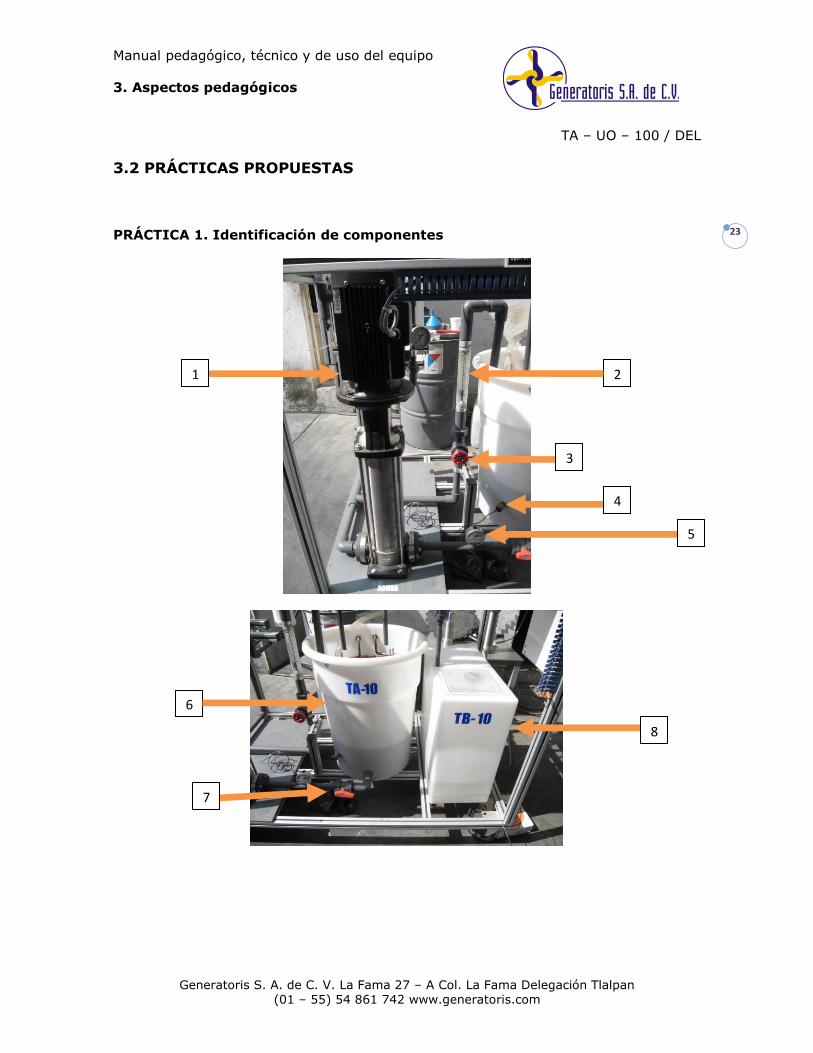
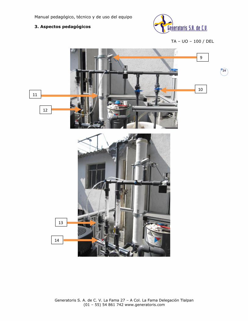
PRÁCTICA 1. Identificación de componentes
1 2
3
4
5
6
7
8
Manual pedagógico, técnico y de uso del equipo
3. Aspectos pedagógicos
TA – UO – 100 / DEL
Generatoris S. A. de C. V. La Fama 27 – A Col. La Fama Delegación Tlalpan
(01 – 55) 54 861 742 www.generatoris.com
24
9
10 11
12
13
14
Manual pedagógico, técnico y de uso del equipo
3. Aspectos pedagógicos
TA – UO – 100 / DEL
Generatoris S. A. de C. V. La Fama 27 – A Col. La Fama Delegación Tlalpan
(01 – 55) 54 861 742 www.generatoris.com
25
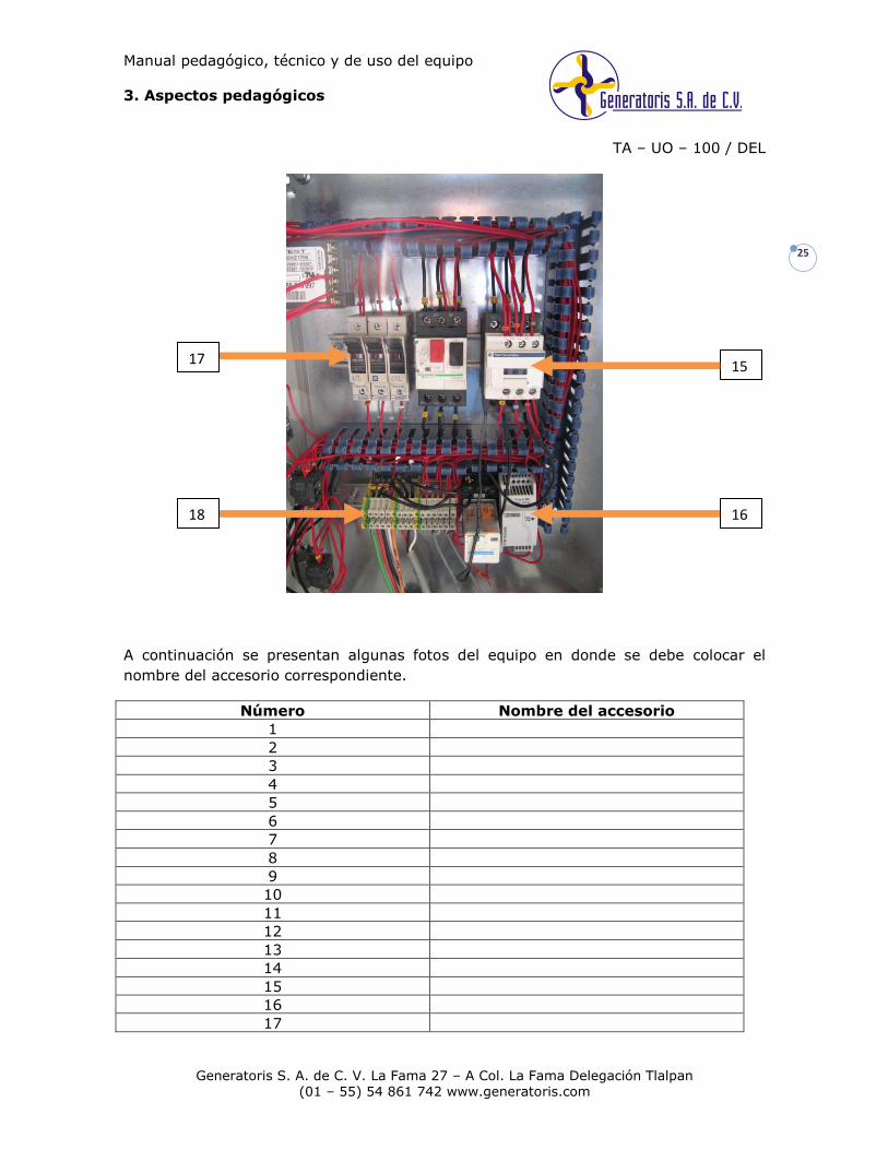
A continuación se presentan algunas fotos del equipo en donde se debe colocar el
nombre del accesorio correspondiente.
Número Nombre del accesorio
1
2
3
4
5
6
7
8
9
10
11
12
13
14
15
16
17
15
16
17
18
Manual pedagógico, técnico y de uso del equipo
3. Aspectos pedagógicos
TA – UO – 100 / DEL
Generatoris S. A. de C. V. La Fama 27 – A Col. La Fama Delegación Tlalpan
(01 – 55) 54 861 742 www.generatoris.com
26
18
Cuestionario
Listar los balances de materia y energía que puedan desarrollarse en el sistema.
¿Cuál es el principio del intercambio iónico?
¿Cuáles son las aplicaciones industriales más comunes? Relacionarlas con el
sistema.
Práctica 2. Obtención de concentración a partir de la conductividad
Objetivo
Aprender un método para calcular concentraciones de electrolitos a partir de valores
experimentales de conductividad, utilizando las leyes de Osanger y Kohlrausch.
Procedimiento de conversión de conductividad a concentración
Se muestra a continuación el procedimiento para convertir valores de conductividad a
expresiones de concentración.
Se da como ejemplo los cálculos para una solución de NaCl.
La ecuación de Osanger relaciona las conductividades iónicas molares para distintas
especies (electrolitos 1:1), la concentración, y a su vez la conductividad (K)
experimental. Dicha ecuación es:
C78.592273.0 00
Esta ecuación aplica para soluciones acuosas; para soluciones no acuosas, la ecuación
es la siguiente:
C155892.0 00
Manual pedagógico, técnico y de uso del equipo
3. Aspectos pedagógicos
TA – UO – 100 / DEL
Generatoris S. A. de C. V. La Fama 27 – A Col. La Fama Delegación Tlalpan
(01 – 55) 54 861 742 www.generatoris.com
27
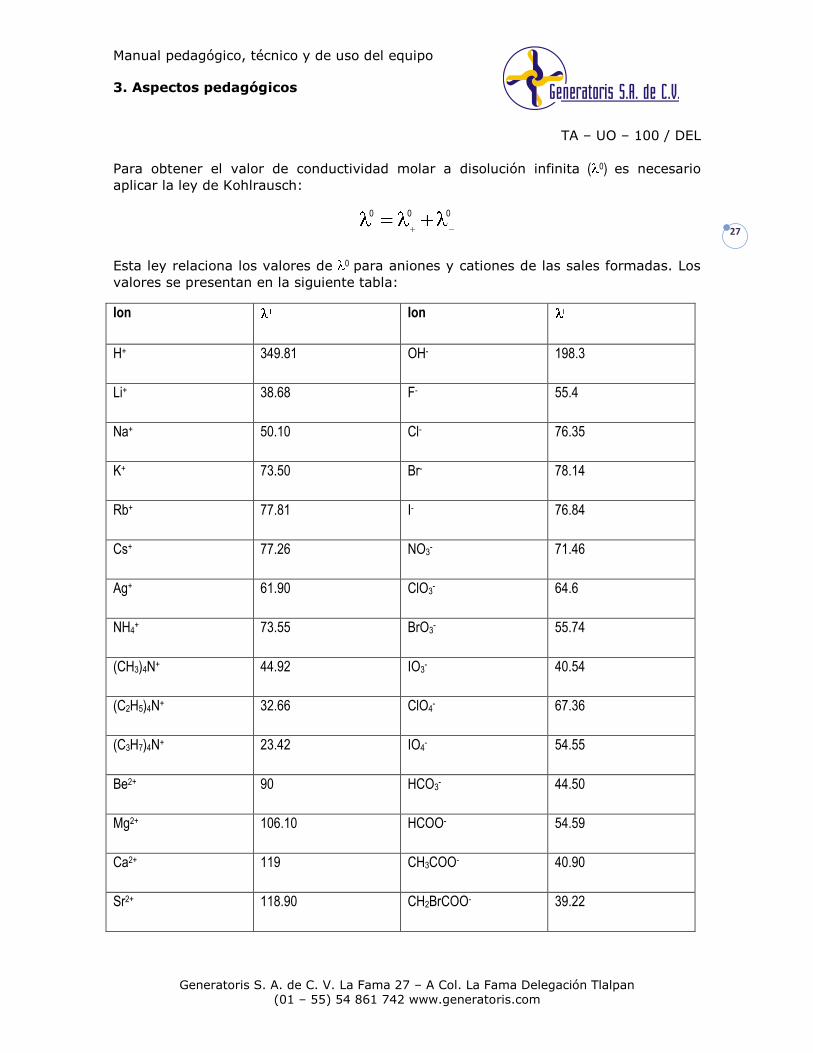
Para obtener el valor de conductividad molar a disolución infinita ( 0) es necesario
aplicar la ley de Kohlrausch:
000
Esta ley relaciona los valores de 0 para aniones y cationes de las sales formadas. Los
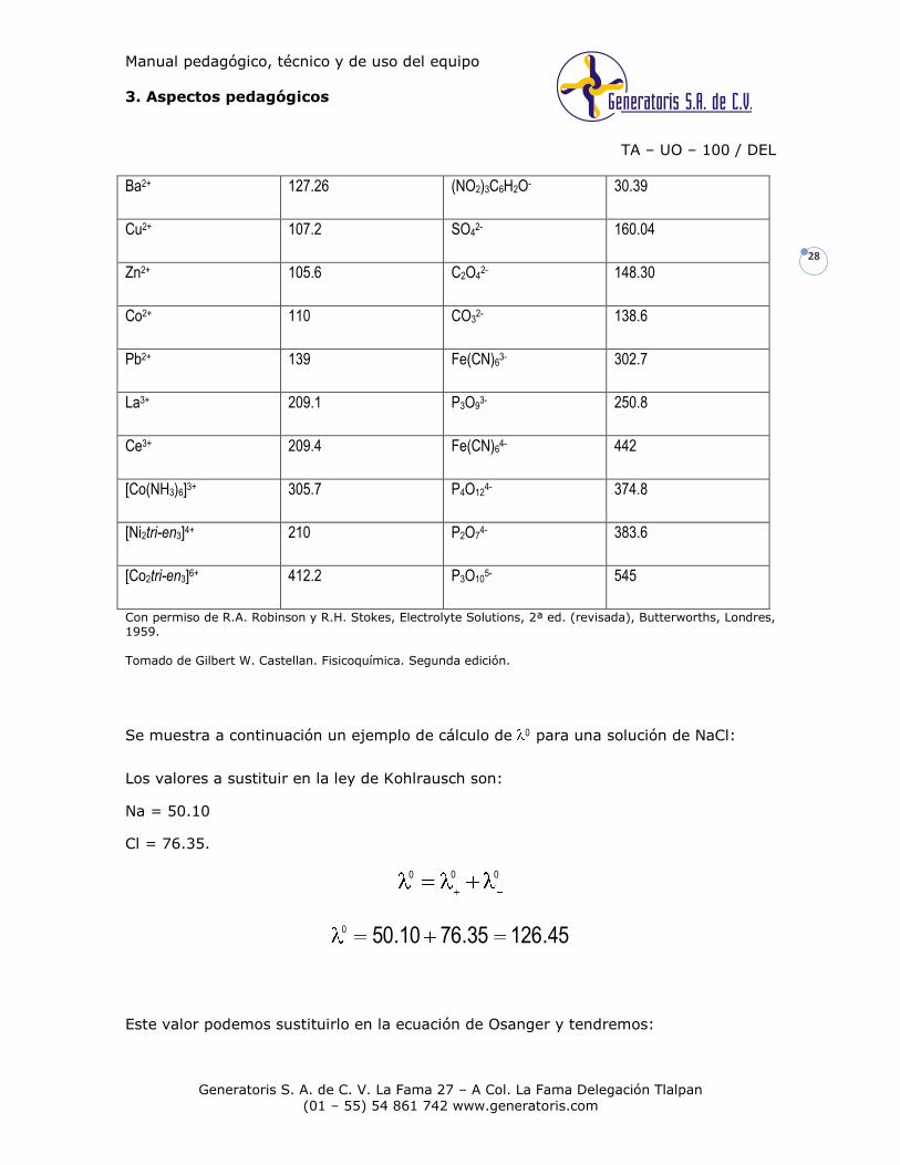
valores se presentan en la siguiente tabla:
Ion Ion
H+ 349.81 OH- 198.3
Li+ 38.68 F- 55.4
Na+ 50.10 Cl- 76.35
K+ 73.50 Br- 78.14
Rb+ 77.81 I- 76.84
Cs+ 77.26 NO3- 71.46
Ag+ 61.90 ClO3- 64.6
NH4+ 73.55 BrO3
- 55.74
(CH3)4N+ 44.92 IO3- 40.54
(C2H5)4N+ 32.66 ClO4- 67.36
(C3H7)4N+ 23.42 IO4- 54.55
Be2+ 90 HCO3- 44.50
Mg2+ 106.10 HCOO- 54.59
Ca2+ 119 CH3COO- 40.90
Sr2+ 118.90 CH2BrCOO- 39.22
Manual pedagógico, técnico y de uso del equipo
3. Aspectos pedagógicos
TA – UO – 100 / DEL
Generatoris S. A. de C. V. La Fama 27 – A Col. La Fama Delegación Tlalpan
(01 – 55) 54 861 742 www.generatoris.com
28
Ba2+ 127.26 (NO2)3C6H2O- 30.39
Cu2+ 107.2 SO42- 160.04
Zn2+ 105.6 C2O42- 148.30
Co2+ 110 CO32- 138.6
Pb2+ 139 Fe(CN)63- 302.7
La3+ 209.1 P3O93- 250.8
Ce3+ 209.4 Fe(CN)64- 442
[Co(NH3)6]3+ 305.7 P4O124- 374.8
[Ni2tri-en3]4+ 210 P2O74- 383.6
[Co2tri-en3]6+ 412.2 P3O105- 545
Con permiso de R.A. Robinson y R.H. Stokes, Electrolyte Solutions, 2ª ed. (revisada), Butterworths, Londres, 1959.
Tomado de Gilbert W. Castellan. Fisicoquímica. Segunda edición.
Se muestra a continuación un ejemplo de cálculo de 0 para una solución de NaCl:
Los valores a sustituir en la ley de Kohlrausch son:
Na = 50.10
Cl = 76.35.
000
45.12635.7610.500
Este valor podemos sustituirlo en la ecuación de Osanger y tendremos:
Manual pedagógico, técnico y de uso del equipo
3. Aspectos pedagógicos
TA – UO – 100 / DEL
Generatoris S. A. de C. V. La Fama 27 – A Col. La Fama Delegación Tlalpan
(01 – 55) 54 861 742 www.generatoris.com
29
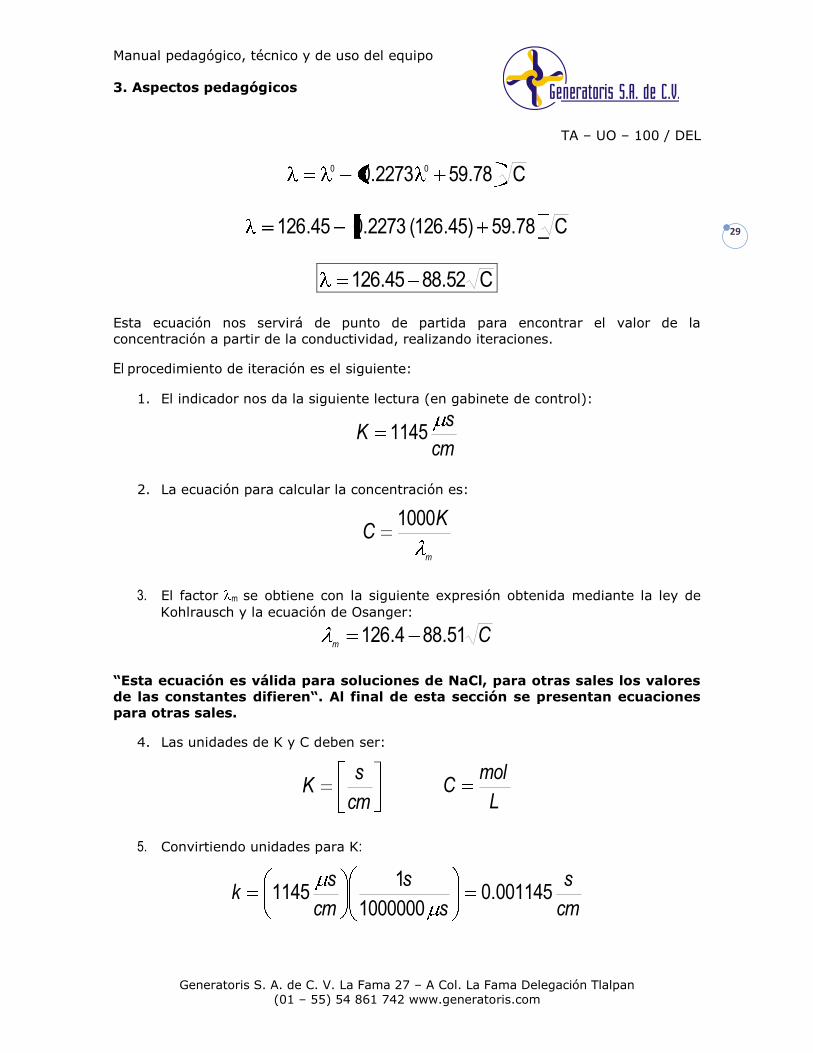
C78.592273.0 00
C78.59)45.126( 2273.045.126
C52.8845.126
Esta ecuación nos servirá de punto de partida para encontrar el valor de la
concentración a partir de la conductividad, realizando iteraciones.
El procedimiento de iteración es el siguiente:
1. El indicador nos da la siguiente lectura (en gabinete de control):
cm
sK 1145
2. La ecuación para calcular la concentración es:
m
KC
1000
3. El factor m se obtiene con la siguiente expresión obtenida mediante la ley de
Kohlrausch y la ecuación de Osanger:
Cm
51.884.126
“Esta ecuación es válida para soluciones de NaCl, para otras sales los valores
de las constantes difieren“. Al final de esta sección se presentan ecuaciones
para otras sales.
4. Las unidades de K y C deben ser:
cm
sK
L
molC
5. Convirtiendo unidades para K:
cm
s
s
s
cm
sk 001145.0
1000000
11145

Manual pedagógico, técnico y de uso del equipo
3. Aspectos pedagógicos
TA – UO – 100 / DEL
Generatoris S. A. de C. V. La Fama 27 – A Col. La Fama Delegación Tlalpan
(01 – 55) 54 861 742 www.generatoris.com
30
6. El valor de la concentración se obtiene mediante iteraciones usando las
ecuaciones del paso 2 y 3.
7. Suponiendo un valor para C: 100 gr en 200 L
L
grC 5.0
L 200
gr 100
8. Convirtiendo unidades:
PM NaCl = 58.45 g/mol
L
mol
grL
grC 00855.0
45.58
NaCl mol 15.0
9. Se sustituye este valor de C en la ecuación de m:
21.11800855.051.884.126m
10. Se calcula el valor de C con su ecuación correspondiente:
L
molC 009686.0
21.118
001145.01000
Esto corresponde a la primera iteración. Con este valor seguiremos haciendo
iteraciones hasta que el valor de C coincida en 5 cifras.
11. Segunda iteración:
L
molC
m
0097290.0689.117
)001145.0(1000
689.117009686.051.884.126
12. Tercera iteración:
Manual pedagógico, técnico y de uso del equipo
3. Aspectos pedagógicos
TA – UO – 100 / DEL
Generatoris S. A. de C. V. La Fama 27 – A Col. La Fama Delegación Tlalpan
(01 – 55) 54 861 742 www.generatoris.com
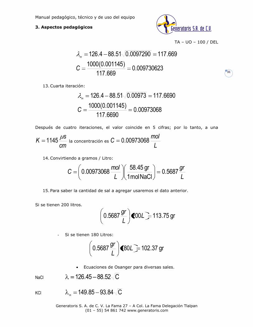
31 009730623.0
669.117
)001145.0(1000
669.1170097290.051.884.126
C
m
13. Cuarta iteración:
00973068.06690.117
)001145.0(1000
6690.11700973.051.884.126
C
m
Después de cuatro iteraciones, el valor coincide en 5 cifras; por lo tanto, a una
cm
sK 1145 la concentración es
L
molC 00973068.0
14. Convirtiendo a gramos / Litro:
L
gr
L
molC 5687.0
NaCl mol 1
gr 45.5800973068.0
15. Para saber la cantidad de sal a agregar usaremos el dato anterior.
Si se tienen 200 litros.
gr 75.1132005687.0 LL
gr
- Si se tienen 180 Litros:
gr 37.1021805687.0 LL
gr
Ecuaciones de Osanger para diversas sales.
NaCl C52.8845.126
KCl C84.9385.149m

Manual pedagógico, técnico y de uso del equipo
3. Aspectos pedagógicos
TA – UO – 100 / DEL
Generatoris S. A. de C. V. La Fama 27 – A Col. La Fama Delegación Tlalpan
(01 – 55) 54 861 742 www.generatoris.com
32
NaOH C24.1164.248m
KOH C56.1218.271m
NaHCOO C57.8369.104m
KHCOO C89.8809.128m
NaCH3COO C46.8091m
KCH3COO C78.854.114m
NaNO3 C41.8756.121m
NaHCO3 C28.816.94m
KHCO3 C60.86118m
Manual pedagógico, técnico y de uso del equipo
4. Documentación
TA – UO – 100 / DEL
Generatoris S. A. de C. V. La Fama 27 – A Col. La Fama Delegación Tlalpan
(01 – 55) 54 861 742 www.generatoris.com
33
4.1 GARANTÍA SOBRE NUESTRO PRODUCTO
GENERATORIS, S.A. DE C.V., GARANTIZA EL CORRECTO FUNCIONAMIENTO DEL
EQUIPO TA – UO – 100 / DEL CON NÚMERO DE SERIE EH-0910-185, POR EL PERÍODO
DE UN AÑO A PARTIR DE LA FECHA DE ENTREGA, CUANDO SU UTILIZACIÓN SE HAYA
AJUSTADO A LAS CONDICIONES DE USO Y MANTENIMIENTO ESTABLECIDAS EN EL
MANUAL, CADUCANDO AUTOMÁTICAMENTE CUANDO SE COMPROBARA QUE EL
EQUIPO HAYA SIDO MODIFICADO PARA FINES AJENOS A SU USO NORMAL.
GENERATORIS, S.A. DE C.V., COMO FABRICANTE DE LOS EQUIPOS, MANIFIESTA EL
COMPROMISO DE REALIZAR LA CONSTRUCCIÓN, INSTALACION Y PUESTA EN MARCHA
DEL EQUIPO MARCA GENERATORISMR O ENTROPIA HUMANAMR DEL PRESENTE MANUAL,
CON TODO LO NECESARIO PARA QUE LOS EQUIPOS QUEDEN CORRECTAMENTE
INSTALADOS Y OPERANDO A SATISFACCION DE EL CLIENTE.
GENERATORIS S.A. DE C.V. COMO FABRICANTE DE LOS EQUIPOS GARANTIZA EL
SUMINISTRO DE PARTES Y REFACCIONES NECESARIAS PARA LOS EQUIPOS
OFERTADOS EN LA LICITACION DE LA MARCA REGISTRADA GENERATORISMR O
ENTROPIA HUMANAMR Y QUE ESTAS SE ENCONTRARAN EN EL MERCADO NACIONAL
POR UN PERIODO MINIMO DE 5 (CINCO) AÑOS.
GENERATORIS, S.A. DE C.V., COMO FABRICANTE DE LOS EQUIPOS, MANIFIESTA EL
COMPROMISO DE REALIZAR UN CURSO DE CAPACITACION PARA EL MANTENIMIENTO
CORRECTIVO Y PREVENTIVO DE LOS EQUIPOS MARCA GENERATORISMR O ENTROPIA
HUMANAMR DE MANERA GRATUITA EL PRIMER AÑO DE FUNCIONAMIENTO.
GENERATORIS, S.A. DE C.V., COMO FABRICANTE DE LOS EQUIPOS, GARANTIZA EL
FUNCIONAMIENTO DE TODAS LAS PIEZAS Y VICIOS OCULTOS DE LOS EQUIPOS
MARCA GENERATORISMR O ENTROPIA HUMANAMR DE MANERA GRATUITA EL PRIMER
AÑO DE FUNCIONAMIENTO.
LOS TÉRMINOS DE LA GARANTÍA NO SIGNIFICA QUE DESPUÉS DEL PLAZO
GARANTIZADO EL EQUIPO SUFRA DETERIOROS CONSIDERABLES.
LA PRESENTE GARANTÍA ES VÁLIDA EXCLUSIVAMENTE PARA EL PROPIETARIO.
_______________________________
Ing. Gorostiza Esteva Eduardo Manuel
Manual pedagógico, técnico y de uso del equipo
4. Documentación
TA – UO – 100 / DEL
Generatoris S. A. de C. V. La Fama 27 – A Col. La Fama Delegación Tlalpan
(01 – 55) 54 861 742 www.generatoris.com
34
4.2 ACTUALIZACIÓN
Este equipo está diseñado para poder desarrollar un mejor trabajo experimental, es
decir, su construcción conlleva a realizar con facilidad ciertas implementaciones; a
continuación se enlistan algunas de ellas que pueden ser pertinentes:
Adquirir una membrana de ultrafiltración intercambiable.
Generatoris está a su servicio, pregunte por nuestros precios y solicite la cotización.
Generatoris S. A. de C. V.
La Fama 27 – A
Col. La Fama
Delegación Tlalpan
(01 – 55) 54861742
servicioacliente@generatoris
www.generatoris.com
Manual pedagógico, técnico y de uso del equipo
4. Documentación
TA – UO – 100 / DEL
Generatoris S. A. de C. V. La Fama 27 – A Col. La Fama Delegación Tlalpan
(01 – 55) 54 861 742 www.generatoris.com
35
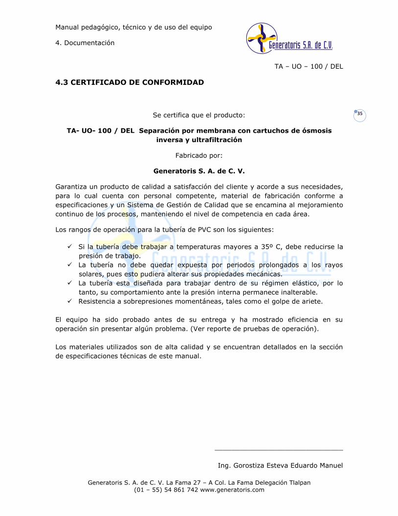
4.3 CERTIFICADO DE CONFORMIDAD
Se certifica que el producto:
TA- UO- 100 / DEL Separación por membrana con cartuchos de ósmosis
inversa y ultrafiltración
Fabricado por:
Generatoris S. A. de C. V.
Garantiza un producto de calidad a satisfacción del cliente y acorde a sus necesidades,
para lo cual cuenta con personal competente, material de fabricación conforme a
especificaciones y un Sistema de Gestión de Calidad que se encamina al mejoramiento
continuo de los procesos, manteniendo el nivel de competencia en cada área.
Los rangos de operación para la tubería de PVC son los siguientes:
Si la tubería debe trabajar a temperaturas mayores a 35º C, debe reducirse la
presión de trabajo.
La tubería no debe quedar expuesta por periodos prolongados a los rayos
solares, pues esto pudiera alterar sus propiedades mecánicas.
La tubería esta diseñada para trabajar dentro de su régimen elástico, por lo
tanto, su comportamiento ante la presión interna permanece inalterable.
Resistencia a sobrepresiones momentáneas, tales como el golpe de ariete.
El equipo ha sido probado antes de su entrega y ha mostrado eficiencia en su
operación sin presentar algún problema. (Ver reporte de pruebas de operación).
Los materiales utilizados son de alta calidad y se encuentran detallados en la sección
de especificaciones técnicas de este manual.
_______________________________
Ing. Gorostiza Esteva Eduardo Manuel
Manual pedagógico, técnico y de uso del equipo
4. Documentación
TA – UO – 100 / DEL
Generatoris S. A. de C. V. La Fama 27 – A Col. La Fama Delegación Tlalpan
(01 – 55) 54 861 742 www.generatoris.com
36
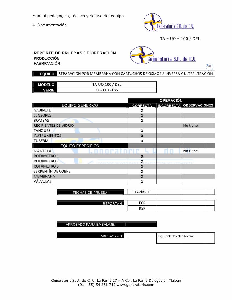
REPORTE DE PRUEBAS DE OPERACIÓN
PRODUCCIÓN
FABRICACIÓN
EQUIPO: SEPARACIÓN POR MEMBRANA CON CARTUCHOS DE ÓSMOSIS INVERSA Y ULTRFILTRACIÓN
MODELO: TA-UO-100 / DEL
SERIE: EH-0910-185
OPERACIÓN
EQUIPO GENERICO CORRECTA INCORRECTA OBSERVACIONES
GABINETE X SENSORES X BOMBAS X RECIPIENTES DE VIDRIO No tiene TANQUES X INSTRUMENTOS X TUBERÍA X
EQUIPO ESPECIFICO MANTILLA No tiene ROTÁMETRO 1 X ROTÁMETRO 2 X ROTÁMETRO 3 X SERPENTÍN DE COBRE X MEMBRANA X VÁLVULAS X
FECHAS DE PRUEBA: 17-dic-10
REPORTAN: ECR
RSP
APROBADO PARA EMBALAJE:
FABRICACIÓN: Ing. Erick Castelán Rivera
Manual pedagógico, técnico y de uso del equipo
TA – UO – 100 /DEL
Generatoris S. A. de C. V. La Fama 27 – A Col. La Fama Delegación Tlalpan
(01 – 55) 54 861 742 www.generatoris.com
38
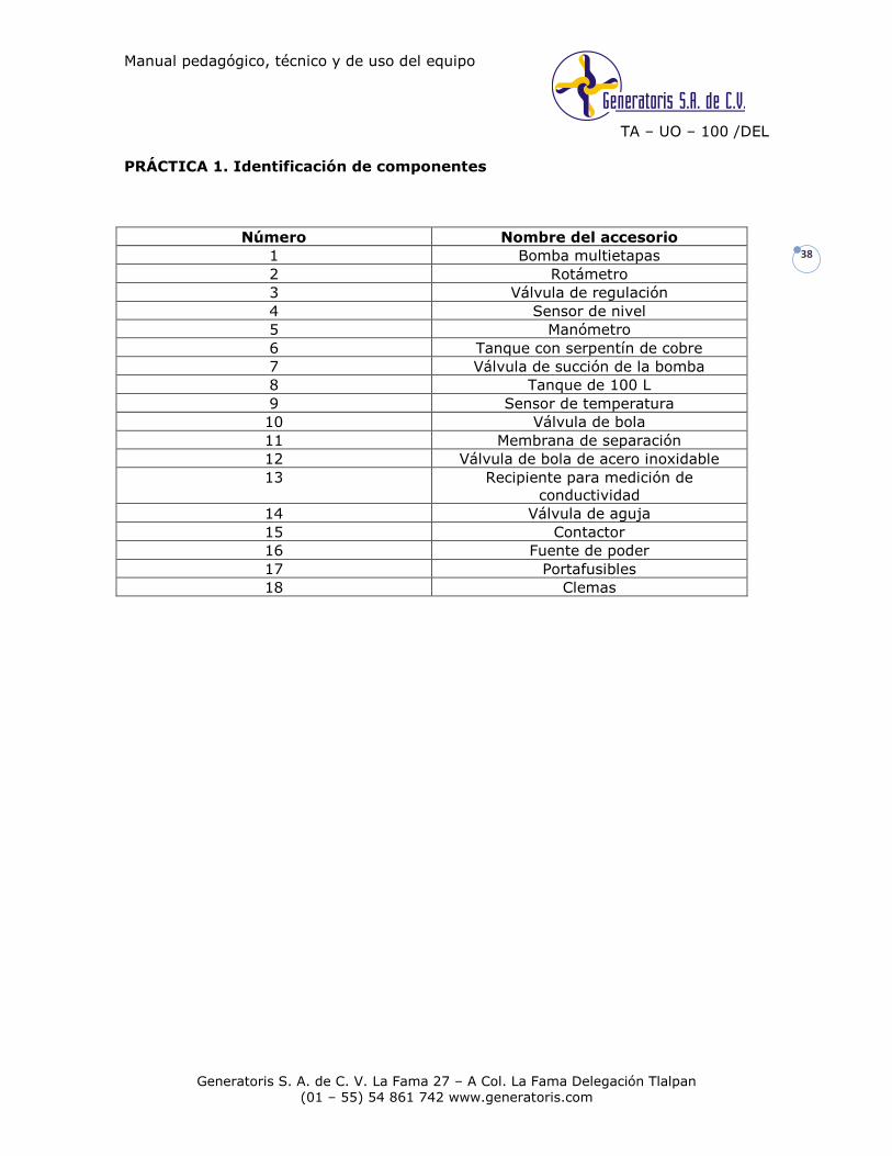
PRÁCTICA 1. Identificación de componentes
Número Nombre del accesorio
1 Bomba multietapas
2 Rotámetro
3 Válvula de regulación
4 Sensor de nivel
5 Manómetro
6 Tanque con serpentín de cobre
7 Válvula de succión de la bomba
8 Tanque de 100 L
9 Sensor de temperatura
10 Válvula de bola
11 Membrana de separación
12 Válvula de bola de acero inoxidable
13 Recipiente para medición de
conductividad
14 Válvula de aguja
15 Contactor
16 Fuente de poder
17 Portafusibles
18 Clemas

Technology Made Easy ...
Instruction Manual CON 6/TDS 6
Hand-held Conductivity/TDS Meter
68X243618
Rev.2 01/04

Preface This manual serves to explain the use of the Conductivity and TDS handheld meters. The models covered are the CON 6 and TDS 6.
This manual functions in two ways: first as a step by step guide to help you operate the meter; second, it serves as a handy reference guide.
This manual is written to cover as many anticipated applications of the Conductivity and TDS handheld meters as possible. If there are doubts in the use of the Conductivity and TDS handheld meters, please do not hesitate to contact the nearest Eutech Instruments/ Oakton Instruments Authorized Distributor.
Eutech Instruments/ Oakton Instruments will not accept any responsibility for damage or malfunction to the meter caused by improper use of the instrument.
The information presented in this manual is subjected to change without notice as improvements are made, and does not represent a commitment on the part of Eutech Instruments Pte Ltd/ Oakton Instruments.
Copyright © 2002
Eutech Instruments Pte Ltd/ Oakton Instruments
All rights reserved. Rev. 2 01/04
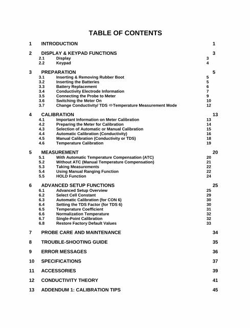
TABLE OF CONTENTS 1 INTRODUCTION 1 2 DISPLAY & KEYPAD FUNCTIONS 3
2.1 Display 3 2.2 Keypad 4
3 PREPARATION 5 3.1 Inserting & Removing Rubber Boot 5 3.2 Inserting the Batteries 5 3.3 Battery Replacement 6 3.4 Conductivity Electrode Information 7 3.5 Connecting the Probe to Meter 9 3.6 Switching the Meter On 10 3.7 Change Conductivity/ TDS Temperature Measurement Mode 12
4 CALIBRATION 13 4.1 Important Information on Meter Calibration 13 4.2 Preparing the Meter for Calibration 14 4.3 Selection of Automatic or Manual Calibration 15 4.4 Automatic Calibration (Conductivity) 16 4.5 Manual Calibration (Conductivity or TDS) 18 4.6 Temperature Calibration 19
5 MEASUREMENT 20 5.1 With Automatic Temperature Compensation (ATC) 20 5.2 Without ATC (Manual Temperature Compensation) 21 5.3 Taking Measurements 22 5.4 Using Manual Ranging Function 22 5.5 HOLD Function 24
6 ADVANCED SETUP FUNCTIONS 25 6.1 Advanced Setup Overview 25 6.2 Select Cell Constant 29 6.3 Automatic Calibration (for CON 6) 30 6.4 Setting the TDS Factor (for TDS 6) 30 6.5 Temperature Coefficient 31 6.6 Normalization Temperature 32 6.7 Single-Point Calibration 32 6.8 Restore Factory Default Values 33
7 PROBE CARE AND MAINTENANCE 34 8 TROUBLE-SHOOTING GUIDE 35 9 ERROR MESSAGES 36 10 SPECIFICATIONS 37 11 ACCESSORIES 39 12 CONDUCTIVITY THEORY 41 13 ADDENDUM 1: CALIBRATION TIPS 45

14 ADDENDUM 2: CALCULATING tDS CONVERSION FACTOR 46 15 Addendum 3: calculating temperature coefficients 47 16 WARRANTY 49 17 RETURN OF ITEMS 50
Instruction Manual CON 6/TDS 6
1
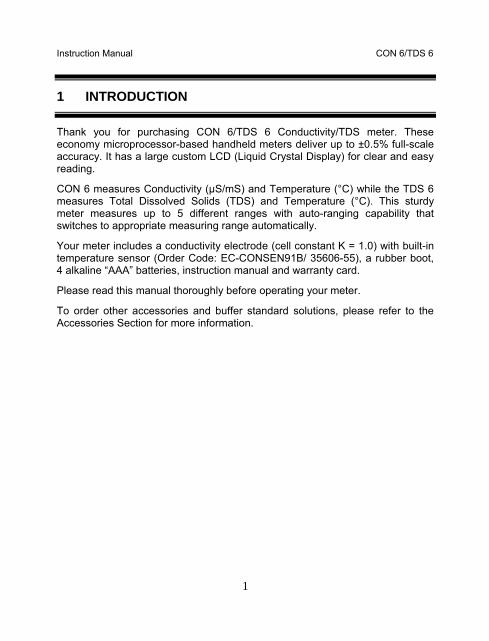
1 INTRODUCTION
Thank you for purchasing CON 6/TDS 6 Conductivity/TDS meter. These economy microprocessor-based handheld meters deliver up to ±0.5% full-scale accuracy. It has a large custom LCD (Liquid Crystal Display) for clear and easy reading.
CON 6 measures Conductivity (µS/mS) and Temperature (°C) while the TDS 6 measures Total Dissolved Solids (TDS) and Temperature (°C). This sturdy meter measures up to 5 different ranges with auto-ranging capability that switches to appropriate measuring range automatically.
Your meter includes a conductivity electrode (cell constant K = 1.0) with built-in temperature sensor (Order Code: EC-CONSEN91B/ 35606-55), a rubber boot, 4 alkaline “AAA” batteries, instruction manual and warranty card.
Please read this manual thoroughly before operating your meter.
To order other accessories and buffer standard solutions, please refer to the Accessories Section for more information.

Instruction Manual CON 6/TDS 6
2
mS
ONOFF
HOLDENTERCAL
MODE
CON 6
Conductivity/ MeterC°
Instruction Manual CON 6/TDS 6
3
2 DISPLAY & KEYPAD FUNCTIONS
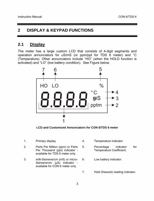
2.1 Display The meter has a large custom LCD that consists of 4-digit segments and operation annunciators for uS/mS (or ppm/ppt for TDS 6 meter) and °C (Temperature). Other annunciators include “HO” (when the HOLD function is activated) and “LO” (low battery condition). See Figure below.
pptm
HO LO %
mSµ
1
234
567
C°
LCD and Customized Annunciators for CON 6/TDS 6 meter
1. Primary display 4. Temperature indicator
2. Parts Per Million (ppm) or Parts Per Thousand (ppt) indicator - available for TDS 6 meter only.
5. Percentage indicator for Temperature Coefficient.
3. milli-Siemens/cm (mS) or micro-Siemens/cm (µS) indicator - available for CON 6 meter only.
6. Low battery indicator.
7. Hold (freezed) reading indicator.

Instruction Manual CON 6/TDS 6
4
2.2 Keypad The CON 6 / TDS 6 meter has 6 keys on its splash-proof keypad; ON/OFF, HOLD/ENTER, CAL, MODE, and keys. Some buttons have several functions depending on its mode of operation.
ONOFF
• Powers on and shuts off the meter. Takes you directly into measurement mode when meter is switched on.
CAL
• Enters into calibration mode for Conductivity/TDS and Temperature.
• To abort calibration or setup mode without confirming any set value.
HOLDENTER
HOLD: Freezes the measured reading. To activate, press HOLD key while in measurement mode. To release, press HOLD key again.
ENTER: Press to confirm values in calibration mode, and to confirm selections in SETUP mode.
• In Calibration Mode: Press to scroll through calibration values. • In Setup Mode: Press to scroll through the setup sub-group
programs. • Press key during conductivity measurement mode to
activate manual ranging function. Each key press will move up higher conductivity range.
MODE
• Selects measurement mode for conductivity/TDS and Temperature.
• When pressed together with ON/OFF key, it will take you into the SETUP mode. This allows you to customize meter preferences such as selecting electrode’s cell constant, normalization temperature, temperature coefficient factor, TDS factor (for TDS 6), automatic (only CON 6) or manual calibration, single-point or multi-point calibrations, and to reset meter to factory default.
Instruction Manual CON 6/TDS 6
5
3 PREPARATION
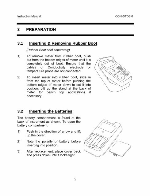
3.1 Inserting & Removing Rubber Boot (Rubber Boot sold separately)
1) To remove meter from rubber boot, push out from the bottom edges of meter until it is completely out of boot. Ensure that the cables of Conductivity electrode or temperature probe are not connected.
2) To insert meter into rubber boot, slide in from the top of meter before pushing the bottom edges of meter down to set it into position. Lift up the stand at the back of meter for bench top applications if necessary.
3.2 Inserting the Batteries The battery compartment is found at the back of instrument as shown. To open the battery compartment:
1) Push in the direction of arrow and lift up the cover.
2) Note the polarity of battery before inserting into position.
3) After replacement, place cover back and press down until it locks tight.

Instruction Manual CON 6/TDS 6
6
3.3 Battery Replacement A “LO” annunciator in the LCD alerts you when battery power is running low. See Figure below. Replace with the same type as recommended by the manufacturer.
LO
Sµ
"LO" Battery Condition
Caution: Power off the meter when changing battery.

Instruction Manual CON 6/TDS 6
7
3.4 Conductivity Electrode Information The CON 6/TDS 6 hand-held meter is supplied with a conductivity/TDS electrode with a BNC connector. This conductivity/TDS electrode (Order Part Number: EC-CONSEN91B/ 35606-55) comes with Stainless Steel rings, cell constant of K = 1.0, and a built-in temperature sensor for Automatic Temperature Compensation (ATC). Its specially designed Ultem-body housing has good chemical resistant properties. It provides fast temperature response and reduces air entrapment, which makes it easy to obtain accurate, stable readings.
The probe materials used which have good chemical durability include:
1. Polyetherimide (Ultem) – protective probe guard
2. Polybutylterphalate (Valox) – sensor housing
3. Stainless Steel (SS 304) – 2 steel bands
Proper use of probe is essential to ensure that the optimum measurement is taken in a short time.
The removable protective plastic probe guard is meant for simple periodic maintenance and it must be kept intact during measurement and calibration.
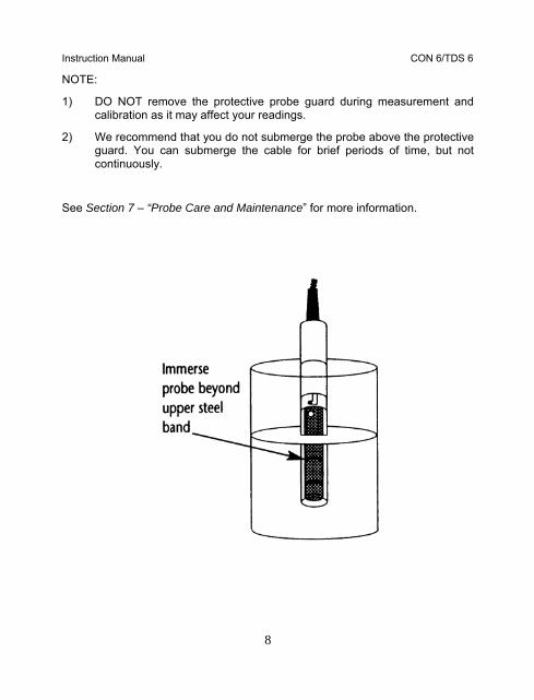
Always immerse the probe beyond upper steel band.
Instruction Manual CON 6/TDS 6
8
NOTE:
1) DO NOT remove the protective probe guard during measurement and calibration as it may affect your readings.
2) We recommend that you do not submerge the probe above the protective guard. You can submerge the cable for brief periods of time, but not continuously.
See Section 7 – “Probe Care and Maintenance” for more information.

Instruction Manual CON 6/TDS 6
9
3.5 Connecting the Probe to Meter 1) To connect electrode into meter, align the connector slots with the posts
of meter’s socket and rotate connector clockwise until it locks.
2) To remove, simply rotate the connector in anti-clockwise direction until it unlocks, and slide the connector off the socket.
3) Insert the mini phono jack of temperature sensor into the socket on the meter as shown below.
4) Unplug the phono jack when not in use or when you want to measure Conductivity or TDS without any temperature compensation (Manual Temperature Compensation, see Section 5.2).
CAUTION: Do not pull or force on the probe cord or the probe wires might disconnect.
NOTE: Keep connectors clean. Do not touch connector with soiled hands.
BNC connector for conductivity probe
Phono jack for Temperature probe
Connection for Conductivity & Temperature Probes
Instruction Manual CON 6/TDS 6
10
Measurement Mode
C°
%
ONOFF
ppm
pptmV
pH %MINMAXLOHOFC° °
mSµ
pptm
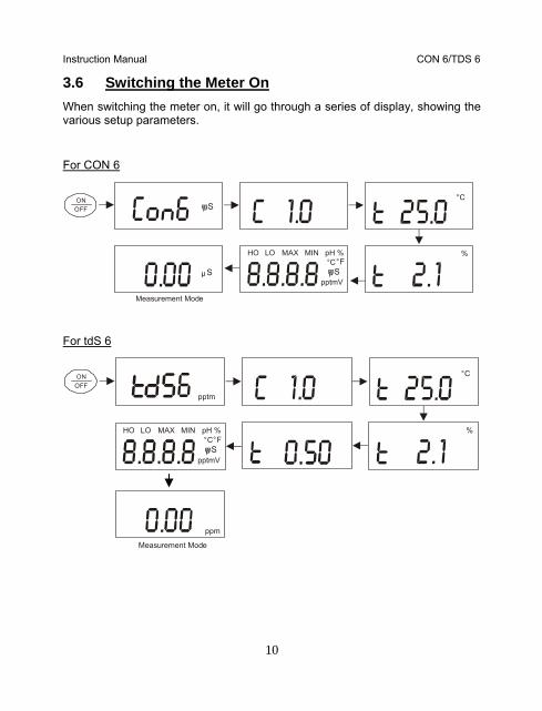
3.6 Switching the Meter On When switching the meter on, it will go through a series of display, showing the various setup parameters.
For CON 6
Measurement Mode
mSµC°
%
pptmV
pH %MINMAXLOHOFC° °
mSµSµ
ONOFF
For tdS 6

Instruction Manual CON 6/TDS 6
11
Press ON/OFF key to power up your meter.
1) The first screen shows [Con 6] (or [tdS 6]) which is the meter’s name.
2) Second screen shows [C 1.0] which is the conductivity cell constant, k. You can select different cell constant of 0.1, 1.0 or 10.0. Refer to Section on Advance Setup. Default value is k=1.0.
3) Third screen shows [t 25.0 °C] which is the Normalization Temperature. You can set Normalization Temperature at either 25 °C or 20 °C. Refer to Section on Advance Setup. Default value is 25 °C.
4) Fourth screen shows [t 2.1%] which is the Temperature Coefficient. You can customise the meter with different Temperature Coefficient value from 0.0 to 3.0 %/°C from the Advance Setup mode. Default value is 2.1 %/°C.
5) All LCD segments will light up for 2 seconds, and change into measurement mode.
6) You are now ready for conductivity measurement.
Instruction Manual CON 6/TDS 6
12
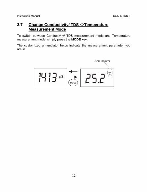
3.7 Change Conductivity/ TDS Temperature Measurement Mode
To switch between Conductivity/ TDS measurement mode and Temperature measurement mode, simply press the MODE key.
The customized annunciator helps indicate the measurement parameter you are in.
Annunciator
MODE
SµC°
Instruction Manual CON 6/TDS 6
13
4 CALIBRATION
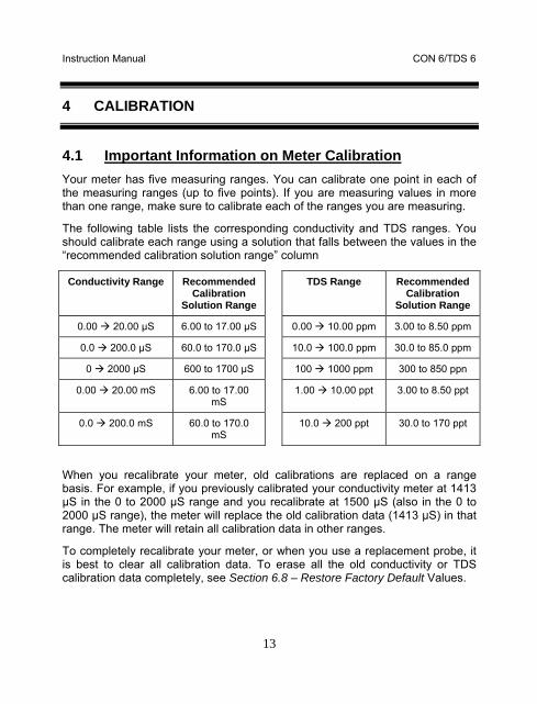
4.1 Important Information on Meter Calibration Your meter has five measuring ranges. You can calibrate one point in each of the measuring ranges (up to five points). If you are measuring values in more than one range, make sure to calibrate each of the ranges you are measuring.
The following table lists the corresponding conductivity and TDS ranges. You should calibrate each range using a solution that falls between the values in the “recommended calibration solution range” column
Conductivity Range Recommended Calibration
Solution Range
TDS Range Recommended Calibration
Solution Range
0.00 20.00 µS 6.00 to 17.00 µS 0.00 10.00 ppm 3.00 to 8.50 ppm
0.0 200.0 µS 60.0 to 170.0 µS 10.0 100.0 ppm 30.0 to 85.0 ppm
0 2000 µS 600 to 1700 µS 100 1000 ppm 300 to 850 ppn
0.00 20.00 mS 6.00 to 17.00 mS
1.00 10.00 ppt 3.00 to 8.50 ppt
0.0 200.0 mS 60.0 to 170.0 mS
10.0 200 ppt 30.0 to 170 ppt
When you recalibrate your meter, old calibrations are replaced on a range basis. For example, if you previously calibrated your conductivity meter at 1413 µS in the 0 to 2000 µS range and you recalibrate at 1500 µS (also in the 0 to 2000 µS range), the meter will replace the old calibration data (1413 µS) in that range. The meter will retain all calibration data in other ranges.
To completely recalibrate your meter, or when you use a replacement probe, it is best to clear all calibration data. To erase all the old conductivity or TDS calibration data completely, see Section 6.8 – Restore Factory Default Values.
Instruction Manual CON 6/TDS 6
14
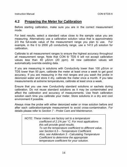
4.2 Preparing the Meter for Calibration Before starting calibration, make sure you are in the correct measurement mode.
For best results, select a standard value close to the sample value you are measuring. Alternatively use a calibration solution value that is approximately 2/3 the full-scale value of the measurement range you plan to use. For example, in the 0 to 2000 µS conductivity range, use a 1413 µS solution for calibration.
Calibrate to all measurement ranges to ensure the highest accuracy throughout all measurement range. Note that CON 6/ TDS 6 will not accept calibration values less than 40 µS/cm (20 ppm). All new calibration values will automatically override existing data.
If you are measuring in solutions with Conductivity lower than 100 µS/cm or TDS lower than 50 ppm, calibrate the meter at least once a week to get good accuracy. If you are measuring in the mid ranges and you wash the probe in deionized water and store it dry, calibrate the meter once a month. If you take measurements at extreme temperatures, calibrate at least once a week.
Ensure that you use new Conductivity standard solutions or sachets during calibration. Do not reuse standard solutions as it may be contaminated and affect the calibration and accuracy of measurements. Use fresh calibration solution each time you calibrate your meter. Store solutions in a dry and cool environment if possible.
Always rinse the probe with either deionized water or rinse solution before and after each calibration/sample measurement to avoid cross-contamination. For details please refer to Section 7 - Probe Care and Maintenance.
NOTE: These meters are factory set to a temperature coefficient of 2.1% per °C. For most applications this will provide good results. To set the temperature coefficient to different value, see Section 6.5 – Temperature Coefficient. Also, see Addendum 3 - Calculating Temperature Coefficient to determine the appropriate temperature coefficient for your solution.
Instruction Manual CON 6/TDS 6
15
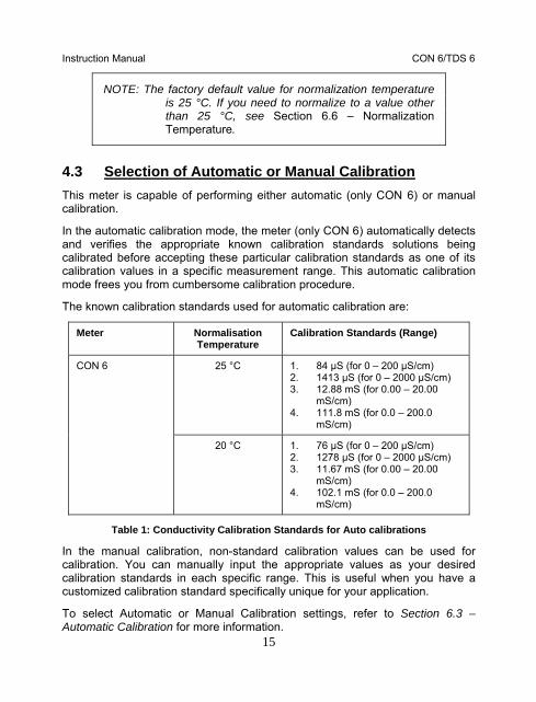
NOTE: The factory default value for normalization temperature is 25 °C. If you need to normalize to a value other than 25 °C, see Section 6.6 – Normalization Temperature.
4.3 Selection of Automatic or Manual Calibration This meter is capable of performing either automatic (only CON 6) or manual calibration.
In the automatic calibration mode, the meter (only CON 6) automatically detects and verifies the appropriate known calibration standards solutions being calibrated before accepting these particular calibration standards as one of its calibration values in a specific measurement range. This automatic calibration mode frees you from cumbersome calibration procedure.
The known calibration standards used for automatic calibration are:
Meter Normalisation Temperature
Calibration Standards (Range)
25 °C 1. 84 µS (for 0 – 200 µS/cm) 2. 1413 µS (for 0 – 2000 µS/cm) 3. 12.88 mS (for 0.00 – 20.00
mS/cm) 4. 111.8 mS (for 0.0 – 200.0
mS/cm)
CON 6
20 °C 1. 76 µS (for 0 – 200 µS/cm) 2. 1278 µS (for 0 – 2000 µS/cm) 3. 11.67 mS (for 0.00 – 20.00
mS/cm) 4. 102.1 mS (for 0.0 – 200.0
mS/cm)
Table 1: Conductivity Calibration Standards for Auto calibrations
In the manual calibration, non-standard calibration values can be used for calibration. You can manually input the appropriate values as your desired calibration standards in each specific range. This is useful when you have a customized calibration standard specifically unique for your application.
To select Automatic or Manual Calibration settings, refer to Section 6.3 – Automatic Calibration for more information.
Instruction Manual CON 6/TDS 6
16
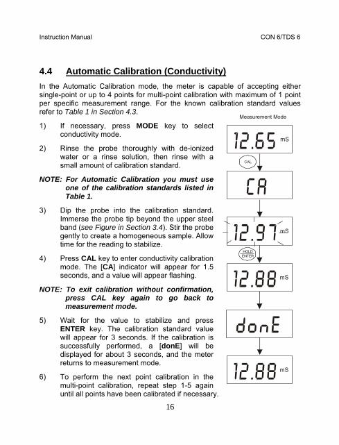
4.4 Automatic Calibration (Conductivity) In the Automatic Calibration mode, the meter is capable of accepting either single-point or up to 4 points for multi-point calibration with maximum of 1 point per specific measurement range. For the known calibration standard values refer to Table 1 in Section 4.3.
1) If necessary, press MODE key to select conductivity mode.
2) Rinse the probe thoroughly with de-ionized water or a rinse solution, then rinse with a small amount of calibration standard.
NOTE: For Automatic Calibration you must use one of the calibration standards listed in Table 1.
3) Dip the probe into the calibration standard. Immerse the probe tip beyond the upper steel band (see Figure in Section 3.4). Stir the probe gently to create a homogeneous sample. Allow time for the reading to stabilize.
4) Press CAL key to enter conductivity calibration mode. The [CA] indicator will appear for 1.5 seconds, and a value will appear flashing.
NOTE: To exit calibration without confirmation, press CAL key again to go back to measurement mode.
5) Wait for the value to stabilize and press ENTER key. The calibration standard value will appear for 3 seconds. If the calibration is successfully performed, a [donE] will be displayed for about 3 seconds, and the meter returns to measurement mode.
6) To perform the next point calibration in the multi-point calibration, repeat step 1-5 again until all points have been calibrated if necessary.
mS
mS
mS
mS
CAL
HOLDENTER
Measurement Mode
Instruction Manual CON 6/TDS 6
17
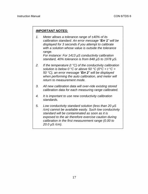
IMPORTANT NOTES:
1. Meter allows a tolerance range of ±40% of its calibration standard. An error message “Err 1” will be displayed for 3 seconds if you attempt to calibrate with a solution whose value is outside the tolerance range. For instance: For 1413 µS conductivity calibration standard, 40% tolerance is from 848 µS to 1978 µS.
2. If the temperature (t °C) of the conductivity calibration solution is below 0 °C or above 50 °C (0°C < t °C > 50 °C), an error message “Err 2” will be displayed when performing the auto calibration, and meter will return to measurement mode.
3. All new calibration data will over-ride existing stored calibration data for each measuring range calibrated.
4. It is important to use new conductivity calibration standards.
5. Low conductivity standard solution (less than 20 µS /cm) cannot be available easily. Such low conductivity standard will be contaminated as soon as it is exposed to the air therefore exercise caution during calibration in the first measurement range (0.00 to 20.0 µS /cm).

Instruction Manual CON 6/TDS 6
18
4.5 Manual Calibration (Conductivity or TDS) In Manual Calibration mode, you can use customized conductivity calibration standards (specific to your own application) and calibrate the meter. The following example shows calibration sequence to 12.00 mS conductivity calibration standard.
Procedure is similar for CON 6 and TDS 6 meters.
1) If necessary, press MODE key to select conductivity mode.
2) Rinse the probe thoroughly with de-ionized water or a rinse solution, then rinse with a small amount of calibration standard.
3) Dip the probe into the calibration standard. Immerse the probe tip beyond the upper steel band (see Figure in Section 3.4). Stir the probe gently to create a homogeneous sample. Allow time for the reading to stabilize.
4) Press CAL key to enter conductivity calibration mode. The [CA] indicator will appear for 1.5 seconds, and a value will appear flashing.
NOTE: To exit calibration without confirmation, press CAL key again to go back to measurement mode.
5) Wait for the value to stabilize and press or key and adjust the value to the calibration standard used.
6) Press the ENTER key. The [CO] indicator will appear for 1.5 seconds, and the calibration is successfully performed. The meter returns to measurement mode.
7) To perform the next point calibration in the multi-point calibration for next range, repeat step 1-6 again until all points have been calibrated if necessary.
mS
mS
mS
mS
CAL
HOLDENTER
Measurement Mode
Instruction Manual CON 6/TDS 6
19
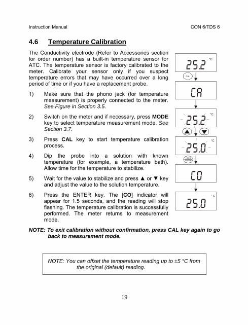
4.6 Temperature Calibration The Conductivity electrode (Refer to Accessories section for order number) has a built-in temperature sensor for ATC. The temperature sensor is factory calibrated to the meter. Calibrate your sensor only if you suspect temperature errors that may have occurred over a long period of time or if you have a replacement probe.
1) Make sure that the phono jack (for temperature measurement) is properly connected to the meter. See Figure in Section 3.5.
2) Switch on the meter and if necessary, press MODE key to select temperature measurement mode. See Section 3.7.
3) Press CAL key to start temperature calibration process.
4) Dip the probe into a solution with known temperature (for example, a temperature bath). Allow time for the temperature to stabilize.
5) Wait for the value to stabilize and press or key and adjust the value to the solution temperature.
6) Press the ENTER key. The [CO] indicator will appear for 1.5 seconds, and the reading will stop flashing. The temperature calibration is successfully performed. The meter returns to measurement mode.
NOTE: To exit calibration without confirmation, press CAL key again to go back to measurement mode.
NOTE: You can offset the temperature reading up to ±5 °C from the original (default) reading.
C°
C°
C°
HOLDENTER
° C
CAL
Instruction Manual CON 6/TDS 6
20
5 MEASUREMENT
The CON 6/TDS 6 meter is capable of taking measurements with automatic or manual temperature compensation.
5.1 With Automatic Temperature Compensation (ATC) For ATC, make sure the phono jack of the probe (see Figure in Section 3.5) is securely inserted.
The conductivity/TDS reading displayed will be compensated for according to the normalization temperature (20 °C or 25 °C) selected. See Section 6.6 – Normalization Temperature.
Instruction Manual CON 6/TDS 6
21
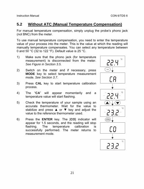
5.2 Without ATC (Manual Temperature Compensation) For manual temperature compensation, simply unplug the probe’s phono jack (not BNC) from the meter.
To use manual temperature compensation, you need to enter the temperature value of your process into the meter. This is the value at which the reading will manually temperature compensates. You can select any temperature between 0 and 50 °C (32 to 122 °F). Default value is 25 °C.
1) Make sure that the phono jack (for temperature measurement) is disconnected from the meter. See Figure in Section 3.5.
2) Switch on the meter and if necessary, press MODE key to select temperature measurement mode. See Section 3.7.
3) Press CAL key to start temperature calibration process.
4) The “CA” will appear momentarily and a temperature value will start flashing.
5) Check the temperature of your sample using an accurate thermometer. Wait for the value to stabilize and press or key and adjust the value to the reference thermometer used.
6) Press the ENTER key. The [CO] indicator will appear for 1.5 seconds, and the reading will stop flashing. The temperature calibration is successfully performed. The meter returns to measurement mode.
C°
C°
C°
HOLDENTER
°C
CAL
Instruction Manual CON 6/TDS 6
22
5.3 Taking Measurements To take readings:
1) Rinse the probe with de-ionized or distilled water before use to remove any impurities adhering to the probe body. Shake or air dry. To avoid contamination or dilution of your sample, rinse probe with a small volume of your sample liquid.
2) Press ON to switch on meter.
3) Dip the probe into the sample.
4) Allow time for the reading to stabilize. Note the reading on the display.
NOTE: When dipping the probe into the sample, take care to ensure that the liquid level is above its upper steel band. Stir the probe gently in the sample to create a homogenous sample. See Figure in Section 3.4.
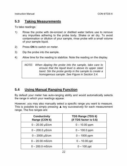
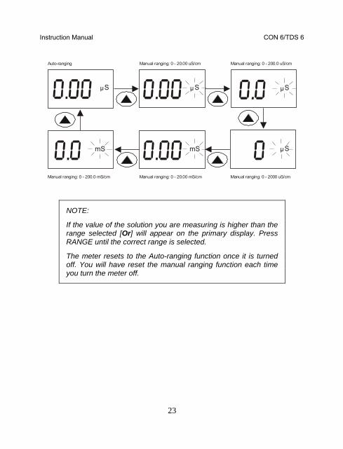
5.4 Using Manual Ranging Function By default your meter has auto-ranging ability and would automatically selects the range in which your readings appear.
However, you may also manually select a specific range you want to measure. This is possible by simply pressing key successively for each measurement range. The five ranges are:
Conductivity Range (CON 6)
TDS Range (TDS 6) (if TDS factor is 0.5)
0 – 20.00 µS/cm 0 – 10.00 ppm
0 – 200.0 µS/cm 0 – 100.0 ppm
0 – 2000 µS/cm 0 – 1000 ppm
0 – 20.00 mS/cm 0 – 10.00 ppt
0 – 200.0 mS/cm 0 – 100 ppt
Instruction Manual CON 6/TDS 6
23
Sµ
mSmS
Auto-ranging Manual ranging: 0 - 20.00 uS/cm Manual ranging: 0 - 200.0 uS/cm
Manual ranging: 0 - 2000 uS/cmManual ranging: 0 - 20.00 mS/cmManual ranging: 0 - 200.0 mS/cm
Sµ Sµ
Sµ
NOTE:
If the value of the solution you are measuring is higher than the range selected [Or] will appear on the primary display. Press RANGE until the correct range is selected.
The meter resets to the Auto-ranging function once it is turned off. You will have reset the manual ranging function each time you turn the meter off.

Instruction Manual CON 6/TDS 6
24
5.5 HOLD Function This feature lets you freeze the display for a delayed observation. HOLD can be used any time in measurement mode.
1) To hold a measurement, press the HOLD key while in measurement mode. [HO] will appear on the display.
2) To release the held value, press the HOLD again. Continue to take measurements.
NOTE:
This meter shuts off automatically after 20 minutes of nonuse.
If the meter is shut off either automatically or manually, the HOLD value will be lost.
Sµ
Sµ
HOLDENTER
HO

Instruction Manual CON 6/TDS 6
25
6 ADVANCED SETUP FUNCTIONS
6.1 Advanced Setup Overview The advanced setup mode lets you customize your meter’s preferences and defaults. To enter advanced setup mode:
1) Make sure that the meter is switched-off.
2) Press ON and MODE key simultaneously, holding both keys for 2 seconds. First release ON key first before releasing the MODE key.
3) [StUP] indicator will appear momentarily and [CELC] will appear next.
4) Overviews of CON 6 and TDS 6’s Setup Menu as follows.
Enter Setup Page.
Select Cell Constant. Choice of k = 0.1, 1.0, and 10.0.
Default value is 1.0.
Select Automatic Calibration. “Yes” for auto calibration and “no” for manual calibration.
Default value is “Yes”. (Available in CON 6 meter only)
%
Adjust Temperature Coefficient value from 0.0 to 3.0 %/°C.
Default value is 2.1 %/°C.
Instruction Manual CON 6/TDS 6
26
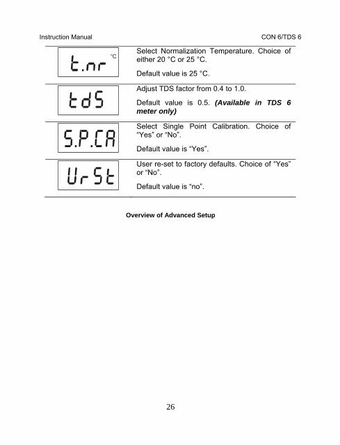
C°
Select Normalization Temperature. Choice of either 20 °C or 25 °C.
Default value is 25 °C.
Adjust TDS factor from 0.4 to 1.0.
Default value is 0.5. (Available in TDS 6 meter only)
Select Single Point Calibration. Choice of “Yes” or “No”.
Default value is “Yes”.
User re-set to factory defaults. Choice of “Yes” or “No”.
Default value is “no”.
Overview of Advanced Setup

Instruction Manual CON 6/TDS 6
27
%
C°
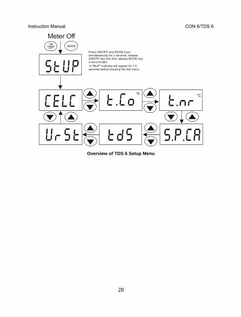
Meter Off
Press ON/OFF and MODE keys simultaneously for 2 seconds, release ON/OFF key first then release MODE key a second later. A "StUP" indicator will appear for 1.5 seconds before showing the first menu
ONOFF MODE
Overview of CON 6 Setup Menu
Instruction Manual CON 6/TDS 6
28
% C°
Meter Off
Press ON/OFF and MODE keys simultaneously for 2 seconds, release ON/OFF key first then release MODE key a second later. A "StUP" indicator will appear for 1.5 seconds before showing the first menu
ONOFF MODE
Overview of TDS 6 Setup Menu
Instruction Manual CON 6/TDS 6
29
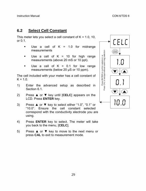
6.2 Select Cell Constant This meter lets you select a cell constant of K = 1.0, 10, or 0.1.
Use a cell of K = 1.0 for midrange measurements
Use a cell of K = 10 for high range measurements (above 20 mS or 10 ppt).
Use a cell of K = 0.1 for low range measurements (below 20 µS or 10 ppm).
The cell included with your meter has a cell constant of K = 1.0.
1) Enter the advanced setup as described in Section 6.1.
2) Press or key until [CELC] appears on the LCD. Press ENTER key.
3) Press or key to select either “1.0”, “0.1” or “10.0”. Ensure the cell constant selected correspond with the conductivity electrode you are using.
4) Press ENTER key to select. The meter will take you back to the menu, [CELC].
5) Press or key to move to the next menu or press CAL to exit to measurement mode.
HOLDENTER
Instruction Manual CON 6/TDS 6
30
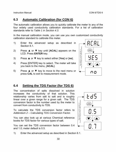
6.3 Automatic Calibration (for CON 6) The automatic calibration allows you to quickly calibrate the meter to any of the four widely used conductivity calibration standards. For a list of calibration standards refer to Table 1 in Section 4.3.
In the manual calibration mode, you can use you own customized conductivity calibration standard to calibrate this meter.
1) Enter the advanced setup as described in Section 6.1.
2) Press or key until [ACAL] appears on the LCD. Press ENTER key.
3) Press or key to select either [Yes] or [no].
4) Press [ENTER] key to select. The meter will take you back to the menu, [ACAL].
5) Press or key to move to the next menu or press CAL to exit to measurement mode.
6.4 Setting the TDS Factor (for TDS 6) The concentration of salts dissolved in solution increases the conductivity of that solution. This relationship varies from salt to salt and is roughly linear over a given range for a given salt. The TDS conversion factor is the number used by the meter to convert from conductivity to TDS.
To calculate the TDS conversion factor refers to Addendum 2 – Calculating TDS Conversion Factor.
You can also look up at various Chemical reference books for TDS factor for various types of salt.
You can set the TDS conversion factor between 0.4 and 1.0; meter default is 0.5.
1) Enter the advanced setup as described in Section 6.1.
HOLDENTER
HOLDENTER

Instruction Manual CON 6/TDS 6
31
2) Press or key until [tdS] appears on the LCD. Press ENTER key.
3) Press or key to select a value between 0.4 to 1.0.
4) Press ENTER key to select. The meter will take you back to the menu, [tdS].
5) Press or key to move to the next menu or press CAL to exit to measurement mode.
6.5 Temperature Coefficient The temperature coefficient is the amount of change in conductivity per degree of temperature; it is expressed in percent per °C. Entering the exact temperature coefficient of your solution lets you accurately compensate temperature for almost any solution. You can adjust 0.0 to 3.0 % per °C.
Meter default is 2.1% per °C.
6) Enter the advanced setup as described in Section 6.1.
7) Press or key until [t.Co %] appears on the LCD. Press ENTER key.
8) Press or key to select a value between 0.0 to 3.0.
9) Press ENTER key to select. The meter will take you back to the menu, [t.Co %].
Press or key to move to the next menu or press CAL to exit to measurement mode.
%
%
%
HOLDENTER
Instruction Manual CON 6/TDS 6
32
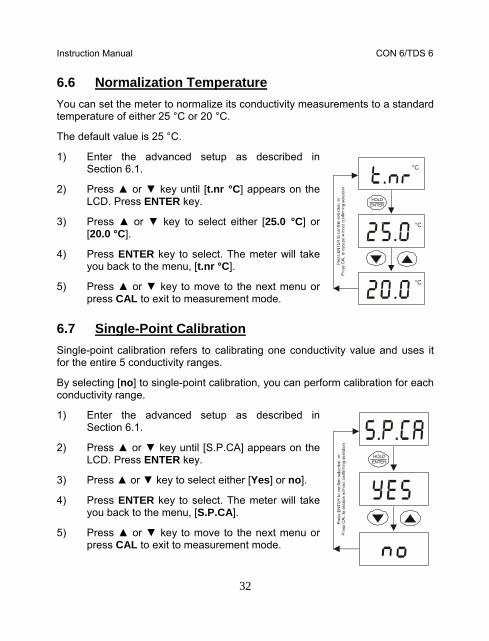
6.6 Normalization Temperature You can set the meter to normalize its conductivity measurements to a standard temperature of either 25 °C or 20 °C.
The default value is 25 °C.
1) Enter the advanced setup as described in Section 6.1.
2) Press or key until [t.nr °C] appears on the LCD. Press ENTER key.
3) Press or key to select either [25.0 °C] or [20.0 °C].
4) Press ENTER key to select. The meter will take you back to the menu, [t.nr °C].
5) Press or key to move to the next menu or press CAL to exit to measurement mode.
6.7 Single-Point Calibration Single-point calibration refers to calibrating one conductivity value and uses it for the entire 5 conductivity ranges.
By selecting [no] to single-point calibration, you can perform calibration for each conductivity range.
1) Enter the advanced setup as described in Section 6.1.
2) Press or key until [S.P.CA] appears on the LCD. Press ENTER key.
3) Press or key to select either [Yes] or no].
4) Press ENTER key to select. The meter will take you back to the menu, [S.P.CA].
5) Press or key to move to the next menu or press CAL to exit to measurement mode.
C°
C°
C°
HOLDENTER
HOLDENTER
Instruction Manual CON 6/TDS 6
33
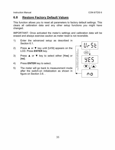
6.8 Restore Factory Default Values This function allows you to reset all parameters to factory default settings. This clears all calibration data and any other setup functions you might have changed.
IMPORTANT: Once activated the meter’s settings and calibration data will be erased and always exercise caution as meter reset is not reversible.
1) Enter the advanced setup as described in Section 6.1.
2) Press or key until [UrSt] appears on the LCD. Press ENTER key.
3) Press or key to select either [Yes] or [no].
4) Press ENTER key to select.
5) The meter will go back to measurement mode after the switch-on initialization as shown in figure on Section 3.6. .
HOLDENTER

Instruction Manual CON 6/TDS 6
34
7 PROBE CARE AND MAINTENANCE
Keep the conductivity probe clean. Rinse the probe twice, and gently swirl it while you take readings. For best accuracy, soak a dry probe for at least 5 to 10 minutes or longer before calibration. Rinse the probe with deionized or tap water before storing. Never scratch the bands with a hard substance. Do not strike the probe against any hard surface.
Do not immerse the probe in oily solutions. Clean the electrode thoroughly by stirring it in a mild detergent bath or isopropyl alcohol. Wipe the probe with a soft tissue paper. Rinse thoroughly in tap water and then in deionized water. Recalibrate the meter after cleaning the probe.
The conductivity probe (Order Part No. EC-CONSEN91B/ 35606-55) which is included with your meter features a removable probe guard to make cleaning easy.
To remove probe guard:
1) Grip yellow probe guard and twist clockwise. The locking notch will release.
2) Slide probe guard off end of probe.
NOTE: Remember to re-attach the probe guard prior to taking readings. Failure to do so could result in erroneous readings.
Instruction Manual CON 6/TDS 6
35
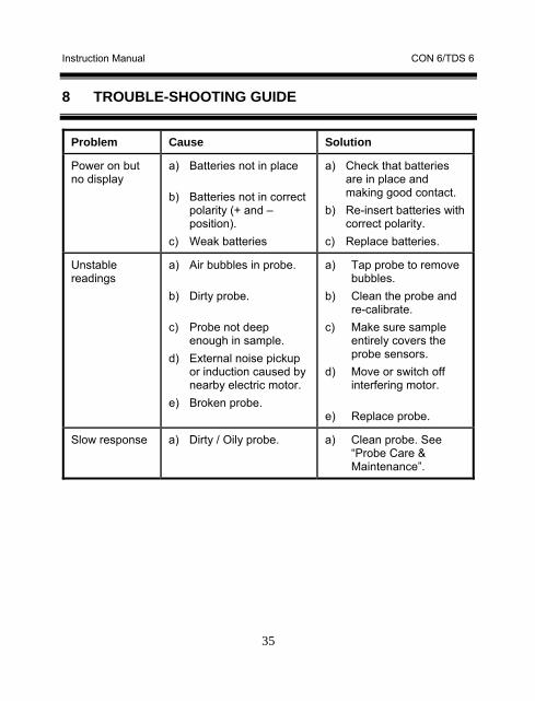
8 TROUBLE-SHOOTING GUIDE
Problem Cause Solution
Power on but no display
a) Batteries not in place
b) Batteries not in correct polarity (+ and – position).
c) Weak batteries
a) Check that batteries are in place and making good contact.
b) Re-insert batteries with correct polarity.
c) Replace batteries.
Unstable readings
a) Air bubbles in probe.
b) Dirty probe.
c) Probe not deep enough in sample.
d) External noise pickup or induction caused by nearby electric motor.
e) Broken probe.
a) Tap probe to remove bubbles.
b) Clean the probe and re-calibrate.
c) Make sure sample entirely covers the probe sensors.
d) Move or switch off interfering motor.
e) Replace probe.
Slow response a) Dirty / Oily probe. a) Clean probe. See “Probe Care & Maintenance”.
Instruction Manual CON 6/TDS 6
36
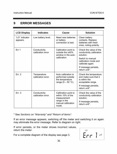
9 ERROR MESSAGES
LCD Display Indicates Cause Solution
“LO” indicator appears.
Low battery level. Need new batteries or battery connection is bad.
Clean battery contacts. Replace batteries with fresh ones, noting polarity.
Err 1 Conductivity calibration error
Calibration point is outside the ±40% window in the auto-calibration.
Check the value of the conductivity calibration solution. Switch to manual calibration mode and calibrate again. If message persists, return unit*.
Err. 2 Temperature calibration error.
Auto calibration is performed outside the temperature range (0 – 50 °C).
Check the temperature and make sure that it is within the acceptable range. If message persists, return unit*.
Err. 3 Conductivity calibration error.
Calibration point is within 10% of the measurement range in the manual calibration mode.
Check the value of the conductivity calibration solution. If message persists, return unit*.
* See Sections on “Warranty” and “Return of Items”.
If an error message appears, switching off the meter and switching it on again may eliminate the error message. Refer to diagram on right.
If error persists, or the meter shows incorrect values, return the meter.
For a complete diagram of the display see page 3.
LO
Sµ
Instruction Manual CON 6/TDS 6
37
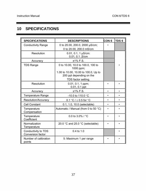
10 SPECIFICATIONS
SPECIFICATIONS DESCRIPTIONS CON 6 TDS 6 Conductivity Range 0 to 20.00, 200.0, 2000 µS/cm;
0 to 20.00, 200.0 mS/cm •
Resolution 0.01, 0.1, 1 µS/cm: 0.01, 0.1 ,S/cm
Accuracy ±1% F.S. TDS Range 0 to 10.00, 10.0 to 100.0, 100 to
1000 ppm; 1.00 to 10.00, 10.00 to 100.0, Up to
200 ppt depending on the TDS factor setting.
•
Resolution 0.01, 0.1, 1 ppm; 0.01, 0.1 ppt
• •
Accuracy ±1% F.S. • • Temperature Range -10.0 to 110.0 °C • • Resolution/Accuracy 0.1 °C / ± 0.5 for °C • • Cell Constant 0.1, 1.0, 10.0 (selectable) • • Temperature Compensation
Automatic / Manual (from 0 to 50 °C) • •
Temperature Coefficient
0.0 to 3.0% / °C • •
Normalization Temperature
20.0 °C and 25.0 °C (selectable) • •
Conductivity to TDS Conversion factor
0.4 to 1.0 •
Number of calibration points
5: Maximum 1 per range • •
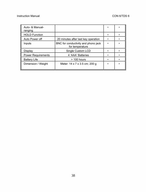
Instruction Manual CON 6/TDS 6
38
Auto- & Manual-ranging
• •
HOLD Function • • Auto Power off 20 minutes after last key operation • • Inputs BNC for conductivity and phono jack
for temperature • •
Display Single Custom LCD • • Power Requirements 4 ‘AAA’ Batteries • • Battery Life > 100 hours • • Dimension / Weight Meter: 14 x 7 x 3.5 cm; 200 g
• •
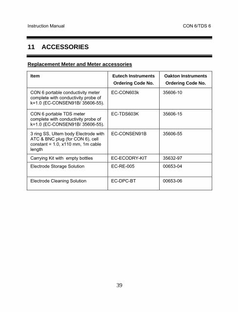
Instruction Manual CON 6/TDS 6
39
11 ACCESSORIES
Replacement Meter and Meter accessories
Item Eutech Instruments Ordering Code No.
Oakton Instruments Ordering Code No.
CON 6 portable conductivity meter complete with conductivity probe of k=1.0 (EC-CONSEN91B/ 35606-55).
EC-CON603k 35606-10
CON 6 portable TDS meter complete with conductivity probe of k=1.0 (EC-CONSEN91B/ 35606-55).
EC-TDS603K 35606-15
3 ring SS, Ultem body Electrode with ATC & BNC plug (for CON 6), cell constant = 1.0, x110 mm, 1m cable length
EC-CONSEN91B 35606-55
Carrying Kit with empty bottles EC-ECODRY-KIT 35632-97
Electrode Storage Solution
EC-RE-005 00653-04
Electrode Cleaning Solution EC-DPC-BT 00653-06
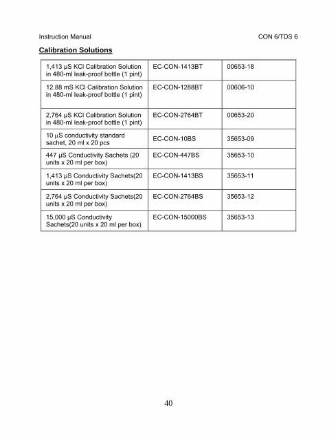
Instruction Manual CON 6/TDS 6
40
Calibration Solutions
1,413 µS KCl Calibration Solution in 480-ml leak-proof bottle (1 pint)
EC-CON-1413BT 00653-18
12.88 mS KCl Calibration Solution in 480-ml leak-proof bottle (1 pint)
EC-CON-1288BT 00606-10
2,764 µS KCl Calibration Solution in 480-ml leak-proof bottle (1 pint)
EC-CON-2764BT 00653-20
10 µS conductivity standard sachet, 20 ml x 20 pcs EC-CON-10BS 35653-09
447 µS Conductivity Sachets (20 units x 20 ml per box)
EC-CON-447BS 35653-10
1,413 µS Conductivity Sachets(20 units x 20 ml per box)
EC-CON-1413BS 35653-11
2,764 µS Conductivity Sachets(20 units x 20 ml per box)
EC-CON-2764BS 35653-12
15,000 µS Conductivity Sachets(20 units x 20 ml per box)
EC-CON-15000BS 35653-13
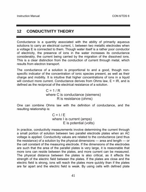
Instruction Manual CON 6/TDS 6
41
12 CONDUCTIVITY THEORY
Conductance is a quantity associated with the ability of primarily aqueous solutions to carry an electrical current, I, between two metallic electrodes when a voltage E is connected to them. Though water itself is a rather poor conductor of electricity, the presence of ions in the water increases its conductance considerably, the current being carried by the migration of the dissolved ions. This is a clear distinction from the conduction of current through metal, which results from electron transport.
The conductance of a solution is proportional to and a good, though non-specific indicator of the concentration of ionic species present, as well as their charge and mobility. It is intuitive that higher concentrations of ions in a liquid will conduct more current. Conductance derives from Ohms law, E = IR, and is defined as the reciprocal of the electrical resistance of a solution.
C = 1 / R where C is conductance (siemens) R is resistance (ohms)
One can combine Ohms law with the definition of conductance, and the resulting relationship is:
C = I / E where I is current (amps) E is potential (volts)
In practice, conductivity measurements involve determining the current through a small portion of solution between two parallel electrode plates when an AC voltage is applied. Conductivity values are related to the conductance (and thus the resistance) of a solution by the physical dimensions --- area and length --- or the cell constant of the measuring electrode. If the dimensions of the electrodes are such that the area of the parallel plates is very large, it is reasonable that more ions can reside between the plates, and more current can be measured. The physical distance between the plates is also critical, as it effects the strength of the electric field between the plates. If the plates are close and the electric field is strong, ions will reach the plates more quickly than if the plates are far apart and the electric field is weak. By using cells with defined plate
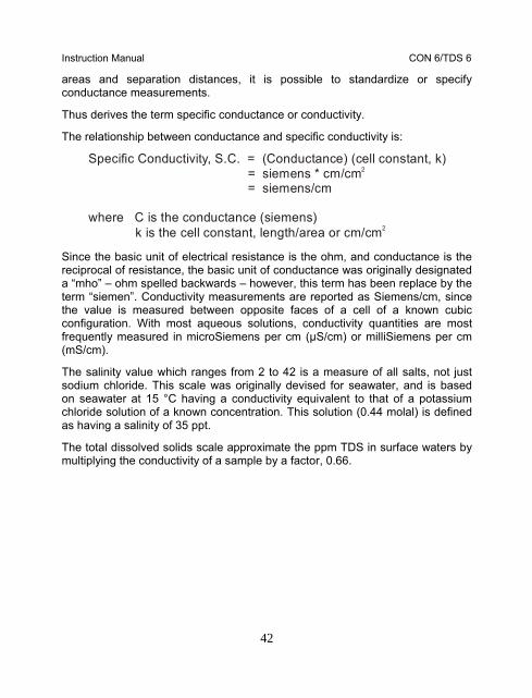
Instruction Manual CON 6/TDS 6
42
areas and separation distances, it is possible to standardize or specify conductance measurements.
Thus derives the term specific conductance or conductivity.
The relationship between conductance and specific conductivity is:
Specific Conductivity, S.C. = (Conductance) (cell constant, k) = siemens * cm/cm = siemens/cm
where C is the conductance (siemens) k is the cell constant, length/area or cm/cm
2
2
Since the basic unit of electrical resistance is the ohm, and conductance is the reciprocal of resistance, the basic unit of conductance was originally designated a “mho” – ohm spelled backwards – however, this term has been replace by the term “siemen”. Conductivity measurements are reported as Siemens/cm, since the value is measured between opposite faces of a cell of a known cubic configuration. With most aqueous solutions, conductivity quantities are most frequently measured in microSiemens per cm (µS/cm) or milliSiemens per cm (mS/cm).
The salinity value which ranges from 2 to 42 is a measure of all salts, not just sodium chloride. This scale was originally devised for seawater, and is based on seawater at 15 °C having a conductivity equivalent to that of a potassium chloride solution of a known concentration. This solution (0.44 molal) is defined as having a salinity of 35 ppt.
The total dissolved solids scale approximate the ppm TDS in surface waters by multiplying the conductivity of a sample by a factor, 0.66.
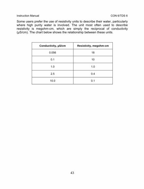
Instruction Manual CON 6/TDS 6
43
Some users prefer the use of resistivity units to describe their water, particularly where high purity water is involved. The unit most often used to describe resistivity is megohm-cm, which are simply the reciprocal of conductivity (µS/cm). The chart below shows the relationship between these units.
Conductivity, µS/cm Resistivity, megohm-cm
0.056 18
0.1 10
1.0 1.0
2.5 0.4
10.0 0.1
Instruction Manual CON 6/TDS 6
44
Conductivity and Temperature
Conductivity in aqueous solutions reflects the concentration, mobility, and charge of the ions in solution. The conductivity of a solution will increase with increasing temperature, as many phenomena influencing conductivity such as solution viscosity are affected by temperature.
The relationship between conductivity and temperature is predictable and usually expressed as relative % change per degree centigrade. This temperature coefficient (% change per degree) depends on the composition of the solution being measured. However, for most medium range salt concentration in water, 2% per degree works well. Extremely pure water exhibits a temperature coefficient of 5.2%, and concentrated salt solutions about 1.5%.
Since temperature affects the conductivity measurement so profoundly, the usual practice is to reference the conductivity to some standard temperature. This is typical 25 °C, but the CON 6 and TDS 6 meters permit the choice of 20 °C or 25 °C in the advance setup menu.
Both meters permit you to enter the temperature coefficient which best suits your sample and use an ATC probe to automatically temperature compensate back to the chosen reference temperature.
Instruction Manual CON 6/TDS 6
45
13 ADDENDUM 1: CALIBRATION TIPS
You only need one calibration for measurement throughout the entire range of the meter. If a range was not calibrated, the meter automatically detects the closest range calibrated and uses that calibration information. However, only the ranges that were calibrated have maximum accuracy.
If you are measuring in ranges near to or greater than 20 mS (10 ppt), or near to or lower than 100 µS (50 ppm), calibrate the meter at least once a week to get specified ±1% F.S. accuracy.
If you are measuring in the mid-ranges and you washed the probe in deionized water and stored it dry, calibrate the meter at least once a month.
Wet the probe for 10 minutes before calibrating or taking readings to saturate the probe surface and minimize drift. If you make measurements at extreme temperatures, calibrate the meter at least once a week.
You should only use the conductivity / TDS probe specified for these meters. These probes have a built-in temperature sensor. If you use a different probe without a temperature sensor, you must measure the solution temperature separately and manually enter the solution temperature (see manual temperature compensation section 5.2)
Instruction Manual CON 6/TDS 6
46
14 ADDENDUM 2: CALCULATING TDS CONVERSION FACTOR
You can calibrate your meter using TDS calibration standard solutions. The calibration standard only needs to give the TDS value at a standard temperature such as 25 °C. To determine the conductivity-to-TDS conversion factor use the following formula:
Factor = Actual TDS ÷ Actual Conductivity @ 25 °C
Definitions:
Actual TDS: Value from the solution bottle label or as a standard you make using high purity water and precisely weighed salts.
Actual Conductivity: Value measured using a properly calibrated Conductivity/Temperature meter.
Both the Actual TDS and the Actual Conductivity values must be in the same magnitude of units. For example, if the TDS value is in ppm the conductivity value must be in µS; if the TDS value is in ppt the conductivity value must be in mS.
Check your factor by multiplying the conductivity reading by the factor in the above formula. The result should be in TDS value.
Instruction Manual CON 6/TDS 6
47
15 ADDENDUM 3: CALCULATING TEMPERATURE COEFFICIENTS
To determine the temperature coefficient of your sample solution use this formula:
Where:
tc = Temperature coefficient 25 = 25 °C
CT1 = Conductivity at Temp 1 CT2 = Conductivity at Temp 2
T1 = Temp 1 T2 = Temp 2
NOTE: A controlled temperature water bath is ideal for this procedure.
1. Immerse the probe into a sample of your solution and adjust the temperature coefficient to 0% (that is, no compensation) by following instructions as described in Section 6.5 – Temperature Coefficient.
2. Wait for 5 minutes. Note T1 and CT1 (conductivity at T1). 3. Condition the sample solution and probe to a temperature (T2) that is about
5 °C to 10 °C different from T1, and note the conductivity reading CT2.
NOTE: Record your results for future reference. Ideally T1 and T2 should bracket your measurement temperature, and should not different by more than 5 °C.

Instruction Manual CON 6/TDS 6
48
4. Calculate the temperature coefficient of your solution according to the formula shown above.
5. Enter the temperature coefficient you calculated into the meter. Refer to Section 6.5 – Temperature Coefficient.
The calculated temperature coefficient will not be applied to all the meter readings.
Instruction Manual CON 6/TDS 6
49
16 WARRANTY
This meter is supplied with a warranty against significant deviations in material and workmanship for a period of THREE years from date of purchase whereas probe with a SIX-month warranty.
If repair or adjustment is necessary and has not been the result of abuse or misuse within the designated period, please return – freight pre-paid – and correction will be made without charge. Eutech Instruments/ Oakton Instruments will determine if the product problem is due to deviations or customer misuse.
Out of warranty products will be repaired on a charged basis.
Exclusions
The warranty on your instrument shall not apply to defects resulting from:
• Improper or inadequate maintenance by customer • Unauthorized modification or misuse • Operation outside of the environment specifications of the products

Instruction Manual CON 6/TDS 6
50
17 RETURN OF ITEMS
Authorization must be obtained from our Customer Service Department or authorized distributor before returning items for any reason. A “Return Goods Authorization” (RGA) form is available through our authorized distributor. Please include data regarding the reason the items are to be returned. For your protection, items must be carefully packed to prevent damage in shipment and insured against possible damage or loss. Eutech Instruments/ Oakton Instruments will not be responsible for damage resulting from careless or insufficient packing. A restocking charge will be made on all unauthorized returns.
NOTE: Eutech Instruments Pte Ltd/ Oakton Instruments reserves the right to make improvements in design, construction, and appearance of products without notice.

Instruction Manual CON 6/TDS 6
51
NOTES

Instruction Manual CON 6/TDS 6
52
For more information on Eutech Instruments/ Oakton Instruments’ products, contact your nearest distributor or visit our website listed below:
Oakton Instruments P.O Box 5136, Vernon Hills, IL60061, USA Fax: (1) 847-247-2984 www.4oakton.com www.oaktoninstruments.com
Eutech Instruments Pte Ltd. Blk 55, Ayer Rajah Crescent, #04-16/24 Singapore 139949 Tel: (65) 6778 6876 Fax: (65) 6773 0836 E-mail: [email protected] Web-site: www.eutechinst.com
Distributed by:

CONDUCTIVITY CELL INSTRUCTION GUIDE
What is Conductivity?
Conductivity (or specifically electrolytic conductivity) is defined as the ability of a
substance to conduct electric current. It is the reciprocal of the more commonly
encountered term, resistivity. All substances possess conductivity to some degree, but the
amount varies widely, ranging from extremely low (insulators such as benzene, glass) to
very high (silver, copper, and metals in general). Most industrial interest is in the
conductivity measurement of liquids. Electric current will readily flow through some
liquids. The less ordered arrangement of the liquid molecules is not conducive to free
electron movement. Therefore, another sort of charged particle must serve this purpose if
any current is to flow at all. In solvents where electrical conductance occurs, notably in
water, ionization will provide the needed carriers. Ionization refers to the tendency of most
soluble inorganic compounds to partially or completely separate into two or more elemental
components, called ions, having opposite electrical charges. These charged particles, or
ions, act as current carriers producing electrolytic current flow. It is the physical
characteristics of the carriers as much as that of the medium that determines electrical
conductance of a solution. These solutions have conductivities approximately midway
between insulators and metallic conductors. This conductivity can be measured quite easily
by electronic means, and this offers a simple test which can tell much about the quality of
the water, or the makeup of the solution. A broad line of conductivity equipment is
available to measure liquids ranging from ultra-pure water (low conductivity) to
concentrated chemical streams (high).
Units of Conductivity
The units of measurement used to describe conductivity and resistivity are quite
fundamental and are frequently misused. Once the units are known, various waters can be
quantitatively described.
The basic unit of resistance is the familiar ohm. Conductance is the reciprocal of resistance,
and its basic unit is the siemens, formerly called mho. In discussions of bulk material, it is
convenient to talk of its specific conductance, now commonly called its conductivity. This
is the conductance as measured between the opposite faces of a 1-cm cube of the material.
This measurement has units of siemens/cm. The units microsiemens/cm (μS/cm) and
millisiemens/cm (mS/cm) are most commonly used to describe the conductivity of aqueous
solutions. The corresponding terms for specific resistance (or resistivity) are ohm-cm (Ω-
cm), megaohm-cm (MΩ -cm) and kilohm-cm (kΩ -cm).
Users of ultra-pure water prefer to use resistivity units of Ω-cm, because measurement in
these units tends to spread the scale out in the range of interest. These same users
frequently use k -cm when dealing with less pure water such as tap water. Others, however,
use the units of μS/cm and mS/cm when dealing with any stream from quite pure to very
concentrated chemical solutions. In these applications, the use of conductivity has the
advantage of an almost direct relationship with impurities, especially at low concentration.
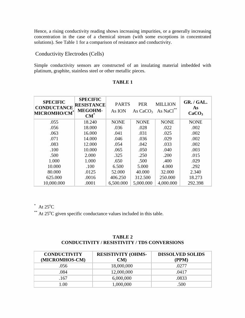
Hence, a rising conductivity reading shows increasing impurities, or a generally increasing
concentration in the case of a chemical stream (with some exceptions in concentrated
solutions). See Table 1 for a comparison of resistance and conductivity.
Conductivity Electrodes (Cells)
Simple conductivity sensors are constructed of an insulating material imbedded with
platinum, graphite, stainless steel or other metallic pieces.
TABLE 1
SPECIFIC
CONDUCTANCE
MICROMHO/CM*
SPECIFIC
RESISTANCE
MEGOHM-
CM*
PARTS PER MILLION
As ION As CaCO3 As NaCl**
GR. / GAL.
As
CaCO3
.055
.056
.063
.071
.083
.100
.500
1.000
10.000
80.000
625.000
10,000.000
18.240
18.000
16.000
14.000
12.000
10.000
2.000
1.000
.100
.0125
.0016
.0001
NONE
.036
.041
.046
.054
.065
.325
.650
6.500
52.000
406.250
6,500.000
NONE
.028
.031
.036
.042
.050
.250
.500
5.000
40.000
312.500
5,000.000
NONE
.022
.025
.029
.033
.040
.200
.400
4.000
32.000
250.000
4,000.000
NONE
.002
.002
.002
.002
.003
.015
.029
.292
2.340
18.273
292.398
* At 25
oC
** At 25
oC given specific conductance values included in this table.
TABLE 2
CONDUCTIVITY / RESISTIVITY / TDS CONVERSIONS
CONDUCTIVITY
(MICROMHOS-CM)
RESISTIVITY (OHMS-
CM)
DISSOLVED SOLIDS
(PPM)
.056 18,000,000 .0277
.084 12,000,000 .0417
.167 6,000,000 .0833
1.00 1,000,000 .500
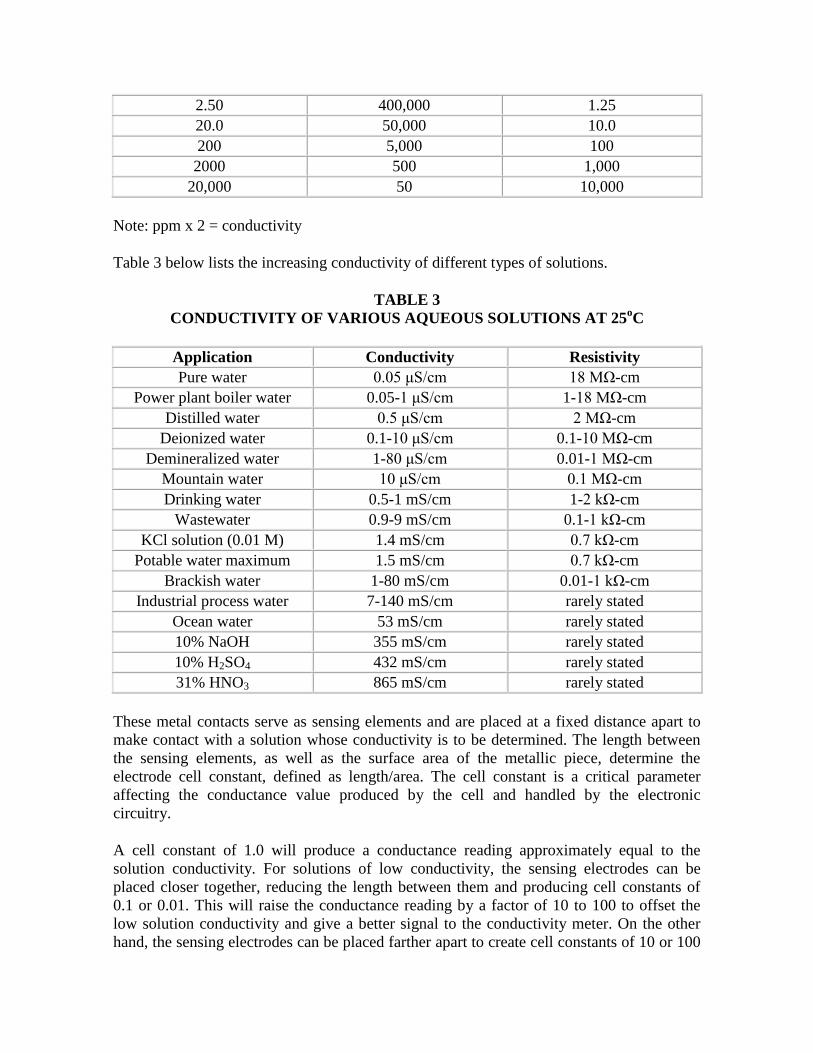
2.50 400,000 1.25
20.0 50,000 10.0
200 5,000 100
2000 500 1,000
20,000 50 10,000
Note: ppm x 2 = conductivity
Table 3 below lists the increasing conductivity of different types of solutions.
TABLE 3
CONDUCTIVITY OF VARIOUS AQUEOUS SOLUTIONS AT 25oC
Application Conductivity Resistivity
Pure water 0.05 μS/cm 18 MΩ-cm
Power plant boiler water 0.05-1 μS/cm 1-18 MΩ-cm
Distilled water 0.5 μS/cm 2 MΩ-cm
Deionized water 0.1-10 μS/cm 0.1-10 MΩ-cm
Demineralized water 1-80 μS/cm 0.01-1 MΩ-cm
Mountain water 10 μS/cm 0.1 MΩ-cm
Drinking water 0.5-1 mS/cm 1-2 kΩ-cm
Wastewater 0.9-9 mS/cm 0.1-1 kΩ-cm
KCl solution (0.01 M) 1.4 mS/cm 0.7 kΩ-cm
Potable water maximum 1.5 mS/cm 0.7 kΩ-cm
Brackish water 1-80 mS/cm 0.01-1 kΩ-cm
Industrial process water 7-140 mS/cm rarely stated
Ocean water 53 mS/cm rarely stated
10% NaOH 355 mS/cm rarely stated
10% H2SO4 432 mS/cm rarely stated
31% HNO3 865 mS/cm rarely stated
These metal contacts serve as sensing elements and are placed at a fixed distance apart to
make contact with a solution whose conductivity is to be determined. The length between
the sensing elements, as well as the surface area of the metallic piece, determine the
electrode cell constant, defined as length/area. The cell constant is a critical parameter
affecting the conductance value produced by the cell and handled by the electronic
circuitry.
A cell constant of 1.0 will produce a conductance reading approximately equal to the
solution conductivity. For solutions of low conductivity, the sensing electrodes can be
placed closer together, reducing the length between them and producing cell constants of
0.1 or 0.01. This will raise the conductance reading by a factor of 10 to 100 to offset the
low solution conductivity and give a better signal to the conductivity meter. On the other
hand, the sensing electrodes can be placed farther apart to create cell constants of 10 or 100
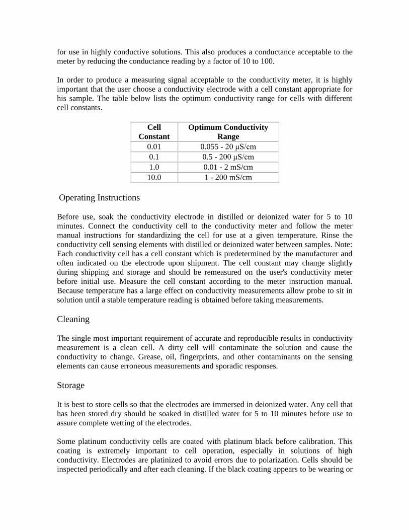
for use in highly conductive solutions. This also produces a conductance acceptable to the
meter by reducing the conductance reading by a factor of 10 to 100.
In order to produce a measuring signal acceptable to the conductivity meter, it is highly
important that the user choose a conductivity electrode with a cell constant appropriate for
his sample. The table below lists the optimum conductivity range for cells with different
cell constants.
Cell
Constant
Optimum Conductivity
Range
0.01 0.055 - 20 μS/cm
0.1 0.5 - 200 μS/cm
1.0 0.01 - 2 mS/cm
10.0 1 - 200 mS/cm
Operating Instructions
Before use, soak the conductivity electrode in distilled or deionized water for 5 to 10
minutes. Connect the conductivity cell to the conductivity meter and follow the meter
manual instructions for standardizing the cell for use at a given temperature. Rinse the
conductivity cell sensing elements with distilled or deionized water between samples. Note:
Each conductivity cell has a cell constant which is predetermined by the manufacturer and
often indicated on the electrode upon shipment. The cell constant may change slightly
during shipping and storage and should be remeasured on the user's conductivity meter
before initial use. Measure the cell constant according to the meter instruction manual.
Because temperature has a large effect on conductivity measurements allow probe to sit in
solution until a stable temperature reading is obtained before taking measurements.
Cleaning
The single most important requirement of accurate and reproducible results in conductivity
measurement is a clean cell. A dirty cell will contaminate the solution and cause the
conductivity to change. Grease, oil, fingerprints, and other contaminants on the sensing
elements can cause erroneous measurements and sporadic responses.
Storage
It is best to store cells so that the electrodes are immersed in deionized water. Any cell that
has been stored dry should be soaked in distilled water for 5 to 10 minutes before use to
assure complete wetting of the electrodes.
Some platinum conductivity cells are coated with platinum black before calibration. This
coating is extremely important to cell operation, especially in solutions of high
conductivity. Electrodes are platinized to avoid errors due to polarization. Cells should be
inspected periodically and after each cleaning. If the black coating appears to be wearing or
flaking off the electrodes or if the cell constant has changed by 50%, the cell should be
cleaned and the electrodes replatinized.
Cleaning Methods
1. For most applications, hot water with domestic cleaning detergent can be used for
cleaning.
2. For lime and other hydroxide containing solutions, clean with a 5-10% solution of
hydrochloric acid.
3. For solutions containing organic fouling agents (fats, oils, etc.), clean probe with
acetone.
4. For algae and bacteria containing solutions, clean probe with a bleach containing
liquid.
Clean cells by dipping or filling the cell with cleaning solution and agitating for two or
three minutes. When a stronger cleaning solution is required, try concentrated hydrochloric
acid mixed into 50% isopropanol. Rinse the cell several times with distilled or deionized
water and remeasure the cell constant before use.
Replatinizing
The platinum electrode should first be cleaned thoroughly in aqua regia being careful not to
dissolve the platinum. If the cell remains too long in aqua regia the platinum elements will
dissolve completely. Prepare a solution of 0.025 N HCl with 3% chloroplatinic acid
(H2PtCl6) and 0.025% lead acetate. Connect the cell to a rheostat or 3-4 V battery to which
a variable resistor has been connected. Immerse cell in the chloroplatinic acid solution and
electrolyze at 10 mA/cm for 10-15 minutes. Reverse the polarity to the cell every 30
seconds until both electrodes are covered with a thin black layer. Disconnect the cell and
save the platinizing solution. It may be reused many times and should not be discarded as it
is expensive to make. Rinse the electrode with tap water for 1 to 2 minutes, followed by
distilled or deionized water. Store in distilled or deionized water until ready for use.
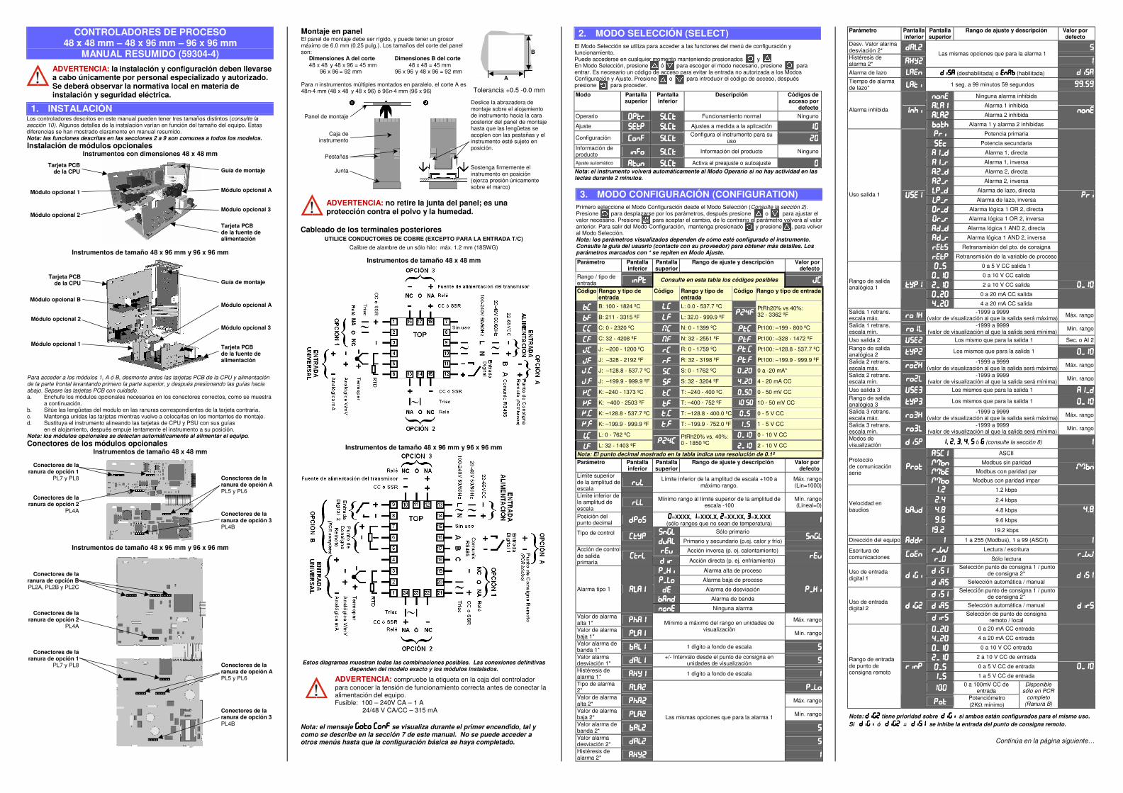
CONTROLADORES DE PROCESO 48 x 48 mm – 48 x 96 mm – 96 x 96 mm
MANUAL RESUMIDO (59304-4)
ADVERTENCIA: la instalación y configuración deben llevarse a cabo únicamente por personal especializado y autorizado. Se deberá observar la normativa local en materia de instalación y seguridad eléctrica.
1. INSTALACIÓN Los controladores descritos en este manual pueden tener tres tamaños distintos (consulte la sección 10). Algunos detalles de la instalación varían en función del tamaño del equipo. Estas diferencias se han mostrado claramente en manual resumido. Nota: las funciones descritas en las secciones 2 a 9 son comunes a todos los modelos. Instalación de módulos opcionales
Instrumentos con dimensiones 48 x 48 mm
Tarjeta PCB de la CPU
Módulo opcional 1
Módulo opcional 2
Guía de montaje
Módulo opcional A
Módulo opcional 3
Tarjeta PCB de la fuente de alimentación
Instrumentos de tamaño 48 x 96 mm y 96 x 96 mm
Tarjeta PCB de la CPU
Módulo opcional B
Módulo opcional 2
Módulo opcional 1
Guía de montaje
Módulo opcional A
Módulo opcional 3 Tarjeta PCB de la fuente de alimentación
Para acceder a los módulos 1, A ó B, desmonte antes las tarjetas PCB de la CPU y alimentación de la parte frontal levantando primero la parte superior, y después presionando las guías hacia abajo. Separe las tarjetas PCB con cuidado. a. Enchufe los módulos opcionales necesarios en los conectores correctos, como se muestra
a continuación. b. Sitúe las lengüetas del modulo en las ranuras correspondientes de la tarjeta contraria. c. Mantenga unidas las tarjetas mientras vuelve a colocarlas en los montantes de montaje. d. Sustituya el instrumento alineando las tarjetas de CPU y PSU con sus guías en el alojamiento, después empuje lentamente el instrumento a su posición. Nota: los módulos opcionales se detectan automáticamente al alimentar el equipo. Conectores de los módulos opcionales
Instrumentos de tamaño 48 x 48 mm
Conectores de la ranura de opción 1
PL7 y PL8
Conectores de la ranura de opción 2
PL4A
Conectores de la ranura de opción A PL5 y PL6
Conectores de la ranura de opción 3 PL4B
Instrumentos de tamaño 48 x 96 mm y 96 x 96 mm
Conectores de la ranura de opción BPL2A, PL2B y PL2C
Conectores de laranura de opción 2
PL4A
Conectores de laranura de opción 1
PL7 y PL8
Conectores de la ranura de opción A PL5 y PL6 Conectores de la ranura de opción 3 PL4B
Montaje en panel El panel de montaje debe ser rígido, y puede tener un grosor máximo de 6.0 mm (0.25 pulg.). Los tamaños del corte del panel son: Dimensiones A del corte Dimensiones B del corte 48 x 48 y 48 x 96 = 45 mm 48 x 48 = 45 mm 96 x 96 = 92 mm 96 x 96 y 48 x 96 = 92 mm Para n instrumentos múltiples montados en paralelo, el corte A es 48n-4 mm (48 x 48 y 48 x 96) ó 96n-4 mm (96 x 96) Tolerancia +0.5 -0.0 mm
Panel de montaje
Caja de instrumento
Pestañas
Junta
Deslice la abrazadera de montaje sobre el alojamiento de instrumento hacia la cara posterior del panel de montaje hasta que las lengüetas se acoplen con las pestañas y el instrumento esté sujeto en posición. Sostenga firmemente el instrumento en posición (ejerza presión únicamente sobre el marco)
ADVERTENCIA: no retire la junta del panel; es una protección contra el polvo y la humedad.
Cableado de los terminales posteriores UTILICE CONDUCTORES DE COBRE (EXCEPTO PARA LA ENTRADA T/C)
Calibre de alambre de un sólo hilo: máx. 1.2 mm (18SWG)
Instrumentos de tamaño 48 x 48 mm
Instrumentos de tamaño 48 x 96 mm y 96 x 96 mm
Estos diagramas muestran todas las combinaciones posibles. Las conexiones definitivas dependen del modelo exacto y los módulos instalados.
ADVERTENCIA: compruebe la etiqueta en la caja del controlador para conocer la tensión de funcionamiento correcta antes de conectar la alimentación del equipo. Fusible: 100 – 240V CA – 1 A 24/48 V CA/CC – 315 mA
Nota: el mensaje se visualiza durante el primer encendido, tal y como se describe en la sección 7 de este manual. No se puede acceder a otros menús hasta que la configuración básica se haya completado.
2. MODO SELECCIÓN (SELECT) El Modo Selección se utiliza para acceder a las funciones del menú de configuración y funcionamiento. Puede accederse en cualquier momento manteniendo presionados y En Modo Selección, presione ó para escoger el modo necesario, presione para entrar. Es necesario un código de acceso para evitar la entrada no autorizada a los Modos Configuración y Ajuste. Presione o para introducir el código de acceso, después presione para proceder.
Modo Pantalla superior
Pantalla inferior
Descripción Códigos de acceso por
defecto Operario Funcionamiento normal Ninguno
Ajuste Ajustes a medida a la aplicación
Configuración Configura el instrumento para su
uso
Información de producto Información del producto Ninguno
Ajuste automático Activa el preajuste o autoajuste Nota: el instrumento volverá automáticamente al Modo Operario si no hay actividad en las teclas durante 2 minutos.
3. MODO CONFIGURACIÓN (CONFIGURATION) Primero seleccione el Modo Configuración desde el Modo Selección (Consulte la sección 2). Presione para desplazarse por los parámetros, después presione o para ajustar el valor necesario. Presione para aceptar el cambio, de lo contrario el parámetro volverá al valor anterior. Para salir del Modo Configuración, mantenga presionado y presione , para volver al Modo Selección. Nota: los parámetros visualizados dependen de cómo esté configurado el instrumento. Consulte la guía del usuario (contacte con su proveedor) para obtener más detalles. Los parámetros marcados con * se repiten en Modo Ajuste. Parámetro Pantalla
inferior Pantalla superior
Rango de ajuste y descripción Valor por defecto
Rango / tipo de entrada Consulte en esta tabla los códigos posibles
Código Rango y tipo de entrada
Código Rango y tipo de entrada
Código Rango y tipo de entrada
bCbCbCbC B: 100 - 1824 ºC LLLL.CCCC L: 0.0 - 537.7 ºC
bFbFbFbF B: 211 - 3315 ºF LLLL.FFFF L: 32.0 - 999.9 ºF P24FP24FP24FP24F
PtRh20% vs 40%: 32 - 3362 ºF
CCCCCCCC C: 0 - 2320 ºC NCNCNCNC N: 0 - 1399 ºC PTCPTCPTCPTC Pt100: –199 - 800 ºC
CFCFCFCF C: 32 - 4208 ºF NFNFNFNF N: 32 - 2551 ºF PtFPtFPtFPtF Pt100: –328 - 1472 ºF
JCJCJCJC J: –200 - 1200 ºC rCrCrCrC R: 0 - 1759 ºC PtPtPtPt.CCCC Pt100: –128.8 - 537.7 ºC
JFJFJFJF J: –328 - 2192 ºF rFrFrFrF R: 32 - 3198 ºF PtPtPtPt.FFFF Pt100: –199.9 - 999.9 ºF
jjjj.CCCC J: –128.8 - 537.7 ºC SCSCSCSC S: 0 - 1762 ºC 0 a -20 mA*
jjjj.FFFF J: –199.9 - 999.9 ºF SFSFSFSF S: 32 - 3204 ºF 4 - 20 mA CC
KCKCKCKC K: –240 - 1373 ºC tCtCtCtC T: –240 - 400 ºC 0 - 50 mV CC
KFKFKFKF K: –400 - 2503 ºF tFtFtFtF T: –400 - 752 ºF .10 - 50 mV CC
kkkk.CCCC K: –128.8 - 537.7 ºC tttt.CCCC T: –128.8 - 400.0 ºC 0 - 5 V CC
KKKK.FFFF K: –199.9 - 999.9 ºF tttt.FFFF T: –199.9 - 752.0 ºF 1 - 5 V CC
LCLCLCLC L: 0 - 762 ºC 0 - 10 V CC
LFLFLFLF L: 32 - 1403 ºF P24CP24CP24CP24C
PtRh20% vs. 40%: 0 - 1850 ºC
2 - 10 V CC
Nota: El punto decimal mostrado en la tabla indica una resolución de 0.1º Parámetro Pantalla
inferior Pantalla superior
Rango de ajuste y descripción Valor por defecto
Límite superior de la amplitud de escala
Límite inferior de la amplitud de escala +100 a
máximo rango. Máx. rango (Lin=1000)
Límite inferior de la amplitud de escala
Mínimo rango al límite superior de la amplitud de
escala -100 Mín. rango (Lineal=0)
Posición del punto decimal
=XXXX, =XXX.X, =XX.XX, =X.XXX (sólo rangos que no sean de temperatura)
Sólo primario Tipo de control
Primario y secundario (p.ej. calor y frío)
Acción inversa (p. ej. calentamiento) Acción de control de salida primaria
Acción directa (p. ej. enfriamiento)
Alarma alta de proceso
Alarma baja de proceso
Alarma de desviación
Alarma de banda
Alarma tipo 1
Ninguna alarma
Valor de alarma alta 1* !!!! Máx. rango
Valor de alarma baja 1*
Mínimo a máximo del rango en unidades de visualización
Mín. rango
Valor alarma de banda 1* 1 dígito a fondo de escala
Valor alarma desviación 1*
+/- Intervalo desde el punto de consigna en unidades de visualización
Histéresis de alarma 1* 1 dígito a fondo de escala
Tipo de alarma 2*
Valor de alarma alta 2* !!!! Máx. rango
Valor de alarma baja 2* Mín. rango
Valor alarma de banda 2*
Valor alarma desviación 2*
Histéresis de alarma 2*
Las mismas opciones que para la alarma 1
Parámetro Pantalla inferior
Pantalla superior
Rango de ajuste y descripción Valor por defecto
Desv. Valor alarma desviación 2*
Histéresis de alarma 2*
Las mismas opciones que para la alarma 1
Alarma de lazo (deshabilitada) o (habilitada) """"Tiempo de alarma de lazo* 1 seg. a 99 minutos 59 segundos ########.####
Ninguna alarma inhibida
Alarma 1 inhibida
Alarma 2 inhibida Alarma inhibida $!$!$!$!
! ! ! ! Alarma 1 y alarma 2 inhibidas
Potencia primaria
% % % % Potencia secundaria
&&&& Alarma 1, directa
Alarma 1, inversa
Alarma 2, directa
Alarma 2, inversa
Alarma de lazo, directa
Alarma de lazo, inversa
Alarma lógica 1 OR 2, directa
Alarma lógica 1 OR 2, inversa
Alarma lógica 1 AND 2, directa
Alarma lógica 1 AND 2, inversa
Retransmisión del pto. de consigna
Uso salida 1 ''''
Retransmisión de la variable de proceso
0 a 5 V CC salida 1
0 a 10 V CC salida
2 a 10 V CC salida
0 a 20 mA CC salida
Rango de salida analógica 1
4 a 20 mA CC salida
Salida 1 retrans. escala máx.
-1999 a 9999 (valor de visualización al que la salida será máxima) Máx. rango
Salida 1 retrans. escala mín.
-1999 a 9999 (valor de visualización al que la salida será mínima) Min. rango
Uso salida 2 '''' Los mismo que para la salida 1 Sec. o AI 2 Rango de salida analógica 2 Los mismos que para la salida 1
Salida 2 retrans. escala máx.
-1999 a 9999 (valor de visualización al que la salida será máxima) Máx. rango
Salida 2 retrans. escala mín.
-1999 a 9999 (valor de visualización al que la salida será mínima) Min. rango
Uso salida 3 '''' Los mismos que para la salida 1 &&&&Rango de salida analógica 3 Los mismos que para la salida 1
Salida 3 retrans. escala máx.
-1999 a 9999 (valor de visualización al que la salida será máxima) Máx. rango
Salida 3 retrans. escala mín.
-1999 a 9999 (valor de visualización al que la salida será mínima) Min. rango
Modos de visualización """" , , , , ó (((( (consulte la sección 8)
$$$$ ASCII
MmMmMmMm Modbus sin paridad
MmMmMmMm Modbus con paridad par
Protocolo de comunicación serie
MmMmMmMm Modbus con paridad impar
MmMmMmMm
. 1.2 kbps
. 2.4 kbps
.)))) 4.8 kbps
####.(((( 9.6 kbps
Velocidad en baudios
####. 19.2 kbps
.))))
Dirección del equipo 1 a 255 (Modbus), 1 a 99 (ASCII)
WwWwWwWw Lectura / escritura Escritura de comunicaciones
Sólo lectura WwWwWwWw
Selección punto de consigna 1 / punto
de consigna 2* Uso de entrada digital 1
"""" Selección automática / manual
Selección punto de consigna 1 / punto
de consigna 2*
"""" Selección automática / manual Uso de entrada digital 2
""""Selección de punto de consigna
remoto / local
0 a 20 mA CC entrada
4 a 20 mA CC entrada
0 a 10 V CC entrada
2 a 10 V CC de entrada
0 a 5 V CC de entrada
1 a 5 V CC de entrada
0 a 100mV CC de
entrada
Rango de entrada de punto de consigna remoto
Potenciómetro (2KΩ mínimo)
Disponible sólo en PCR
completo (Ranura B)
Nota: tiene prioridad sobre si ambos están configurados para el mismo uso. Si ó = se inhibe la entrada del punto de consigna remoto.
Continúa en la página siguiente…
A
B
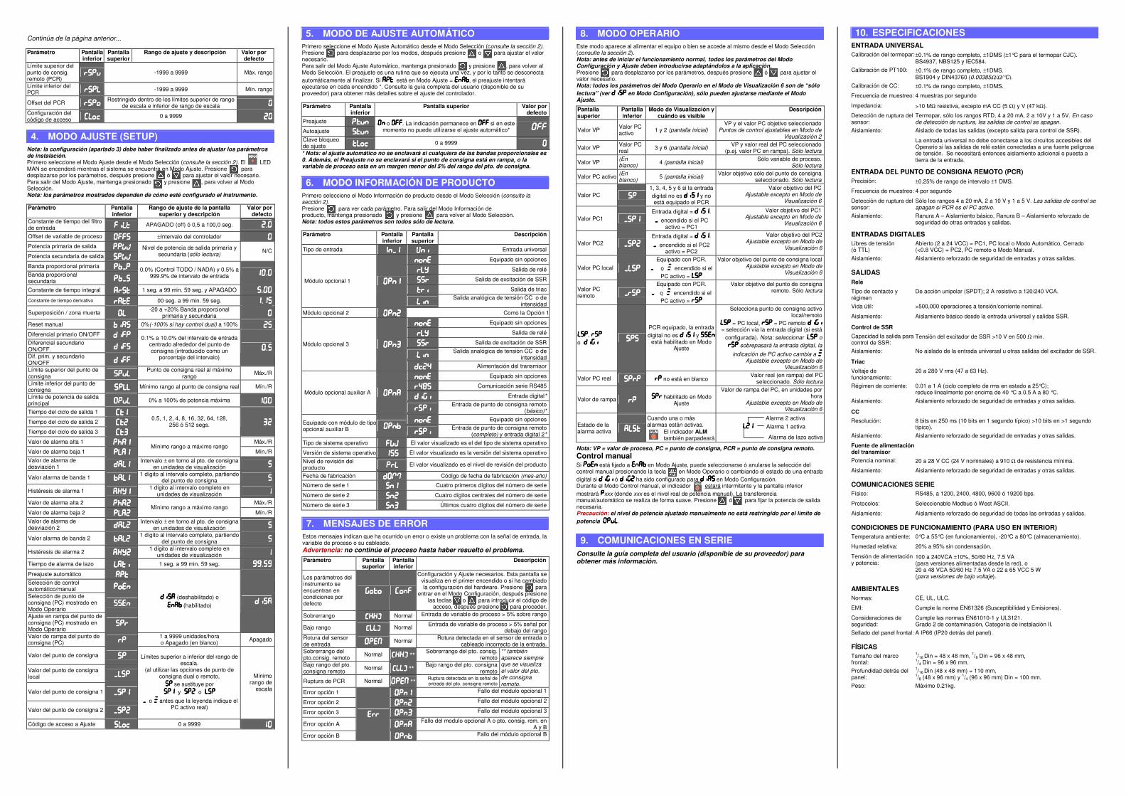
Continúa de la página anterior...
Parámetro Pantalla inferior
Pantalla superior
Rango de ajuste y descripción Valor por defecto
Límite superior del punto de consig. remoto (PCR)
-1999 a 9999 Máx. rango
Límite inferior del PCR -1999 a 9999 Mín. rango
Offset del PCR Restringido dentro de los límites superior de rango
de escala e inferior de rango de escala Configuración del código de acceso %%%% 0 a 9999
4. MODO AJUSTE (SETUP) Nota: la configuración (apartado 3) debe haber finalizado antes de ajustar los parámetros de instalación. Primero seleccione el Modo Ajuste desde el Modo Selección (consulte la sección 2). El LED MAN se encenderá mientras el sistema se encuentra en Modo Ajuste. Presione para desplazarse por los parámetros, después presione ó para ajustar el valor necesario. Para salir del Modo Ajuste, mantenga presionado y presione , para volver al Modo Selección. Nota: los parámetros mostrados dependen de cómo esté configurado el instrumento.
Parámetro Pantalla inferior
Rango de ajuste de la pantalla superior y descripción
Valor por defecto
Constante de tiempo del filtro de entrada APAGADO (off) ó 0,5 a 100,0 seg. .
Offset de variable de proceso ±Intervalo del controlador
Potencia primaria de salida WwWwWwWw Potencia secundaria de salida WwWwWwWw
Nivel de potencia de salida primaria y secundaria (sólo lectura) N/C
Banda proporcional primaria Banda proporcional secundaria
0.0% (Control TODO / NADA) y 0.5% a 999.9% de intervalo de entrada .
Constante de tiempo integral """" 1 seg. a 99 min. 59 seg. y APAGADO .Constante de tiempo derivativo 00 seg. a 99 min. 59 seg. .
Superposición / zona muerta -20 a +20% Banda proporcional
primaria y secundaria
Reset manual 0%(-100% si hay control dual) a 100%
Diferencial primario ON/OFF Diferencial secundario ON/OFF.
Dif. prim. y secundario ON/OFF
0.1% a 10.0% del intervalo de entrada centrado alrededor del punto de consigna (introducido como un
porcentaje del intervalo) .
Límite superior del punto de consigna
Punto de consigna real al máximo rango Máx./R
Límite inferior del punto de consigna Mínimo rango al punto de consigna real Mín./R
Límite de potencia de salida principal 0% a 100% de potencia máxima
Tiempo del ciclo de salida 1
Tiempo del ciclo de salida 2
Tiempo del ciclo de salida 3
0.5, 1, 2, 4, 8, 16, 32, 64, 128, 256 ó 512 segs.
Valor de alarma alta 1 !!!! Máx./R
Valor de alarma baja 1 Mínimo rango a máximo rango
Mín./R Valor de alarma de desviación 1
Intervalo ± en torno al pto. de consigna en unidades de visualización
Valor alarma de banda 1 1 dígito al intervalo completo, partiendo
del punto de consigna
Histéresis de alarma 1 1 dígito al intervalo completo en
unidades de visualización
Valor de alarma alta 2 !!!! Máx./R
Valor de alarma baja 2 Mínimo rango a máximo rango
Mín./R Valor de alarma de desviación 2
Intervalo ± en torno al pto. de consigna en unidades de visualización
Valor alarma de banda 2 1 dígito al intervalo completo, partiendo
del punto de consigna
Histéresis de alarma 2 1 dígito al intervalo completo en
unidades de visualización
Tiempo de alarma de lazo 1 seg. a 99 min. 59 seg. ########.####Preajuste automático Selección de control automático/manual
Selección de punto de consigna (PC) mostrado en Modo Operario
Ajuste en rampa del punto de consigna (PC) mostrado en Modo Operario
(deshabilitado) o (habilitado)
Valor de rampa del punto de consigna (PC)
1 a 9999 unidades/hora o Apagado (en blanco) Apagado
Valor del punto de consigna
Valor del punto de consigna local
Valor del punto de consigna 1
Valor del punto de consigna 2
Límites superior a inferior del rango de escala.
(al utilizar las opciones de punto de consigna dual o remoto, se sustituye por y o
o **** antes que la leyenda indique el PC activo real)
Mínimo rango de
escala
Código de acceso a Ajuste %%%% 0 a 9999
5. MODO DE AJUSTE AUTOMÁTICO Primero seleccione el Modo Ajuste Automático desde el Modo Selección (consulte la sección 2). Presione para desplazarse por los modos, después presione o para ajustar el valor necesario. Para salir del Modo Ajuste Automático, mantenga presionado y presione , para volver al Modo Selección. El preajuste es una rutina que se ejecuta una vez, y por lo tanto se desconecta automáticamente al finalizar. Si está en Modo Ajuste = , el preajuste intentará ejecutarse en cada encendido *. Consulte la guía completa del usuario (disponible de su proveedor) para obtener más detalles sobre el ajuste del controlador.
Parámetro Pantalla inferior
Pantalla superior Valor por defecto
Preajuste
Autoajuste
o . La indicación permanece en si en este momento no puede utilizarse el ajuste automático* OffOffOffOff
Clave bloqueo de ajuste %%%% 0 a 9999
* Nota: el ajuste automático no se enclavará si cualquiera de las bandas proporcionales es 0. Además, el Preajuste no se enclavará si el punto de consigna está en rampa, o la variable de proceso esta en un margen menor del 5% del rango del pto. de consigna.
6. MODO INFORMACIÓN DE PRODUCTO Primero seleccione el Modo Información de producto desde el Modo Selección (consulte la sección 2). Presione para ver cada parámetro. Para salir del Modo Información de producto, mantenga presionado y presione , para volver al Modo Selección. Nota: todos estos parámetros son todos sólo de lectura.
Parámetro Pantalla inferior
Pantalla superior
Descripción
Tipo de entrada $$$$ '''' Entrada universal
Equipado sin opciones
**** Salida de relé
Salida de excitación de SSR
Salida de triac Módulo opcional 1
Salida analógica de tensión CC o de
intensidad Módulo opcional 2 Como la Opción 1
Equipado sin opciones
**** Salida de relé
Salida de excitación de SSR
Salida analógica de tensión CC o de
intensidad
Módulo opcional 3
%%%% Alimentación del transmisor
Equipado sin opciones
)))) Comunicación serie RS485
Entrada digital* Módulo opcional auxiliar A
Entrada de punto de consigna remoto
(básico)*
Equipado sin opciones Equipado con módulo de tipo opcional auxiliar B
Entrada de punto de consigna remoto
(completo) y entrada digital 2* Tipo de sistema operativo +,+,+,+, El valor visualizado es el del tipo de sistema operativo
Versión de sistema operativo $""$""$""$"" El valor visualizado es la versión del sistema operativo Nivel de revisión del producto El valor visualizado es el nivel de revisión del producto
Fecha de fabricación MmMmMmMm Código de fecha de fabricación (mes-año)
Número de serie 1 Cuatro primeros dígitos del número de serie
Número de serie 2 Cuatro dígitos centrales del número de serie
Número de serie 3 Últimos cuatro dígitos del número de serie
7. MENSAJES DE ERROR Estos mensajes indican que ha ocurrido un error o existe un problema con la señal de entrada, la variable de proceso o su cableado. Advertencia: no continúe el proceso hasta haber resuelto el problema. Parámetro Pantalla
superior Pantalla inferior
Descripción
Los parámetros del instrumento se encuentran en condiciones por defecto
Configuración y Ajuste necesarios. Esta pantalla se visualiza en el primer encendido o si ha cambiado la configuración del hardware. Presione para
entrar en el Modo Configuración, después presione las teclas o para introducir el código de
acceso, después presione para proceder.
Sobrerrango ----.... Normal Entrada de variable de proceso > 5% sobre rango
Bajo rango ----.... Normal Entrada de variable de proceso > 5% señal por debajo del rango
Rotura del sensor de entrada //// Normal Rotura detectada en el sensor de entrada o
cableado incorrecto de la entrada. Sobrerrango del pto.consig. remoto Normal ----.... **
Sobrerrango del pto. consig. remoto
Bajo rango del pto. consigna remoto Normal ----.... **
Bajo rango del pto. consigna remoto
Ruptura de PCR Normal //// **Ruptura detectada en la señal de entrada del pto. consigna remoto
** también aparece siempre que se visualiza el valor del pto. de consigna remoto.
Error opción 1 Fallo del módulo opcional 1
Error opción 2 Fallo del módulo opcional 2
Error opción 3 Fallo del módulo opcional 3
Error opción A Fallo del modulo opcional A o pto. consig. rem. en
A y B Error opción B
Fallo del módulo opcional B
8. MODO OPERARIO Este modo aparece al alimentar el equipo o bien se accede al mismo desde el Modo Selección (consulte la sección 2). Nota: antes de iniciar el funcionamiento normal, todos los parámetros del Modo Configuración y Ajuste deben introducirse adaptándolos a la aplicación. Presione para desplazarse por los parámetros, después presione ó para ajustar el valor necesario. Nota: todos los parámetros del Modo Operario en el Modo de Visualización 6 son de “sólo lectura” (ver en Modo Configuración), sólo pueden ajustarse mediante el Modo Ajuste. Pantalla superior
Pantalla inferior
Modo de Visualización y cuándo es visible
Descripción
Valor VP Valor PC activo 1 y 2 (pantalla inicial)
VP y el valor PC objetivo seleccionado Puntos de control ajustables en Modo de
Visualización 2
Valor VP Valor PC real 3 y 6 (pantalla inicial) VP y valor real del PC seleccionado
(p.ej. valor PC en rampa). Sólo lectura
Valor VP (En blanco) 4 (pantalla inicial) Sólo variable de proceso.
Sólo lectura
Valor PC activo (En blanco) 5 (pantalla inicial) Valor objetivo sólo del punto de consigna
seleccionado. Sólo lectura
Valor PC
1, 3, 4, 5 y 6 si la entrada digital no es y no está equipado el PCR
Valor objetivo del PC Ajustable excepto en Modo de
Visualización 6
Valor PC1
Entrada digital = . _ encendido si el PC
activo = PC1
Valor objetivo del PC1 Ajustable excepto en Modo de
Visualización 6
Valor PC2
Entrada digital = .
_ encendido si el PC2 activo = PC2
Valor objetivo del PC2 Ajustable excepto en Modo de
Visualización 6
Valor PC local
Equipado con PCR.
_ o **** encendido si el PC activo =
Valor objetivo del punto de consigna local Ajustable excepto en Modo de
Visualización 6
Valor PC remoto
Equipado con PCR.
_o **** encendido si el PC activo =
Valor objetivo del punto de consigna remoto. Sólo lectura
, o """"
PCR equipado, la entrada digital no es y
está habilitado en Modo Ajuste
Selecciona punto de consigna activo local/remoto
= PC local, = PC remoto = selección vía la entrada digital (si está
configurada). Nota: seleccionar o sobrepasará la entrada digital, la
indicación de PC activo cambia a **** Ajustable excepto en Modo de
Visualización 6
Valor PC real no está en blanco Valor real (en rampa) del PC
seleccionado. Sólo lectura
Valor de rampa habilitado en Modo
Ajuste
Valor de rampa del PC, en unidades por hora
Ajustable excepto en Modo de Visualización 6
Estado de la alarma activa
Cuando una o más alarmas están activas.
El indicador ALM también parpadeará
Alarma 2 activa Alarma 1 activa
Alarma de lazo activa
Nota: VP = valor de proceso, PC = punto de consigna, PCR = punto de consigna remoto. Control manual Si está fijado a en Modo Ajuste, puede seleccionarse ó anularse la selección del control manual presionando la tecla en Modo Operario o cambiando el estado de una entrada digital si ó ha sido configurado para """" en Modo Configuración. Durante el Modo Control manual, el indicador estará intermitente y la pantalla inferior mostrará xxx (donde xxx es el nivel real de potencia manual). La transferencia manual/automático se realiza de forma suave. Presione ó para fijar la potencia de salida necesaria. Precaución: el nivel de potencia ajustado manualmente no está restringido por el límite de potencia .
9. COMUNICACIONES EN SERIE Consulte la guía completa del usuario (disponible de su proveedor) para obtener más información.
10. ESPECIFICACIONES ENTRADA UNIVERSAL Calibración del termopar:±0.1% de rango completo, ±1DMS (±1°C para el termopar CJC).
BS4937, NBS125 y IEC584. Calibración de PT100: ±0.1% de rango completo, ±1DMS.
BS1904 y DIN43760 (0.00385Ω/Ω/°C). Calibración de CC: ±0.1% de rango completo, ±1DMS.
Frecuencia de muestreo: 4 muestras por segundo
Impedancia: >10 MΩ resistiva, excepto mA CC (5 Ω) y V (47 kΩ).
Detección de ruptura del sensor:
Termopar, sólo los rangos RTD, 4 a 20 mA, 2 a 10V y 1 a 5V. En caso de detección de ruptura, las salidas de control se apagan.
Aislamiento: Aislado de todas las salidas (excepto salida para control de SSR).
La entrada universal no debe conectarse a los circuitos accesibles del Operario si las salidas de relé están conectadas a una fuente peligrosa de tensión. Se necesitará entonces aislamiento adicional o puesta a tierra de la entrada.
ENTRADA DEL PUNTO DE CONSIGNA REMOTO (PCR) Precisión: ±0.25% de rango de intervalo ±1 DMS.
Frecuencia de muestreo: 4 por segundo
Detección de ruptura del sensor:
Sólo los rangos 4 a 20 mA, 2 a 10 V y 1 a 5 V. Las salidas de control se apagan si PCR es el PC activo.
Aislamiento: Ranura A – Aislamiento básico, Ranura B – Aislamiento reforzado de seguridad de otras entradas y salidas.
ENTRADAS DIGITALES Libres de tensión (ó TTL)
Abierto (2 a 24 VCC) = PC1, PC local o Modo Automático, Cerrado (<0.8 VCC) = PC2, PC remoto o Modo Manual.
Aislamiento: Aislamiento reforzado de seguridad de entradas y otras salidas.
SALIDAS Relé Tipo de contacto y régimen
De acción unipolar (SPDT); 2 A resistivo a 120/240 VCA.
Vida útil: >500,000 operaciones a tensión/corriente nominal.
Aislamiento: Aislamiento básico desde la entrada universal y salidas SSR.
Control de SSR Capacidad la salida para control de SSR:
Tensión del excitador de SSR >10 V en 500 Ω min.
Aislamiento: No aislado de la entrada universal u otras salidas del excitador de SSR.
Triac Voltaje de funcionamiento:
20 a 280 V rms (47 a 63 Hz).
Régimen de corriente: 0.01 a 1 A (ciclo completo de rms en estado a 25°C); reduce linealmente por encima de 40 °C a 0.5 A a 80 °C.
Aislamiento: Aislamiento reforzado de seguridad de entradas y otras salidas.
CC Resolución: 8 bits en 250 ms (10 bits en 1 segundo típico) >10 bits en >1 segundo
típico). Aislamiento: Aislamiento reforzado de seguridad de entradas y otras salidas.
Fuente de alimentación del transmisor
Potencia nominal: 20 a 28 V CC (24 V nominales) a 910 Ω de resistencia mínima.
Aislamiento: Aislamiento reforzado de seguridad de entradas y otras salidas.
COMUNICACIONES SERIE Físico: RS485, a 1200, 2400, 4800, 9600 ó 19200 bps.
Protocolos: Seleccionable Modbus ó West ASCII.
Aislamiento: Aislamiento reforzado de seguridad de todas las entradas y salidas.
CONDICIONES DE FUNCIONAMIENTO (PARA USO EN INTERIOR) Temperatura ambiente: 0°C a 55°C (en funcionamiento), -20°C a 80°C (almacenamiento).
Humedad relativa: 20% a 95% sin condensación.
Tensión de alimentación y potencia:
100 a 240VCA ±10%, 50/60 Hz, 7.5 VA (para versiones alimentadas desde la red), o 20 a 48 VCA 50/60 Hz 7.5 VA o 22 a 65 VCC 5 W (para versiones de bajo voltaje).
AMBIENTALES Normas: CE, UL, ULC.
EMI: Cumple la norma EN61326 (Susceptibilidad y Emisiones).
Consideraciones de seguridad:
Cumple las normas EN61010-1 y UL3121. Grado 2 de contaminación, Categoría de instalación II.
Sellado del panel frontal: A IP66 (IP20 detrás del panel).
FÍSICAS Tamaño del marco frontal:
1/16 Din = 48 x 48 mm, 1/8 Din = 96 x 48 mm, 1/4 Din = 96 x 96 mm.
Profundidad detrás del panel:
1/16 Din (48 x 48 mm) = 110 mm, 1/8 (48 x 96 mm) y 1/4 (96 x 96 mm) Din = 100 mm.
Peso: Máximo 0.21kg.
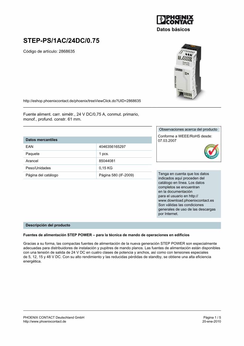
PHOENIX CONTACT Deutschland GmbH Página 1 / 5http://www.phoenixcontact.de 20-ene-2010
Datos básicos
STEP-PS/1AC/24DC/0.75Código de artículo: 2868635
http://eshop.phoenixcontact.de/phoenix/treeViewClick.do?UID=2868635
Fuente aliment. carr. simétr., 24 V DC/0,75 A, conmut. primario,monof., profund. constr. 61 mm.
Datos mercantiles
EAN 4046356165297
Paquete 1 pcs.
Arancel 85044081
Peso/Unidades 0,15 KG
Página del catálogo Página 580 (IF-2009)
Observaciones acerca del producto
Conforme a WEEE/RoHS desde:07.03.2007
Tenga en cuenta que los datosindicados aquí proceden delcatálogo en línea. Los datoscompletos se encuentranen la documentaciónpara el usuario en http://www.download.phoenixcontact.esSon válidas las condicionesgenerales de uso de las descargaspor Internet.
Descripción del producto
Fuentes de alimentación STEP POWER – para la técnica de mando de operaciones en edificios
Gracias a su forma, las compactas fuentes de alimentación de la nueva generación STEP POWER son especialmenteadecuadas para distribuidores de instalación y pupitres de mando planos. Las fuentes de alimentación están disponiblescon una tensión de salida de 24 V DC en cuatro clases de potencia y anchos, así como con tensiones especialesde 5, 12, 15 y 48 V DC. Con su alto rendimiento y las reducidas pérdidas de standby, se obtiene una alta eficienciaenergética.
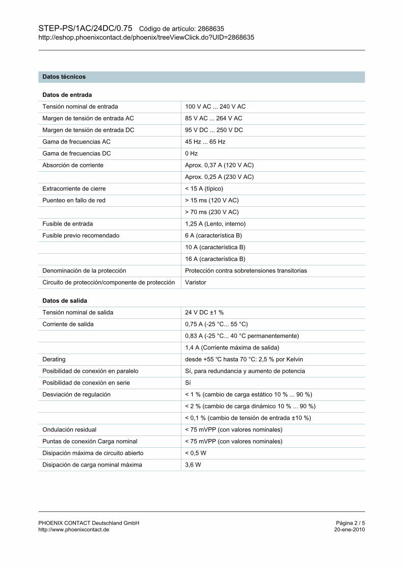
STEP-PS/1AC/24DC/0.75 Código de artículo: 2868635http://eshop.phoenixcontact.de/phoenix/treeViewClick.do?UID=2868635
PHOENIX CONTACT Deutschland GmbH Página 2 / 5http://www.phoenixcontact.de 20-ene-2010
Datos técnicos
Datos de entrada
Tensión nominal de entrada 100 V AC ... 240 V AC
Margen de tensión de entrada AC 85 V AC ... 264 V AC
Margen de tensión de entrada DC 95 V DC ... 250 V DC
Gama de frecuencias AC 45 Hz ... 65 Hz
Gama de frecuencias DC 0 Hz
Absorción de corriente Aprox. 0,37 A (120 V AC)
Aprox. 0,25 A (230 V AC)
Extracorriente de cierre < 15 A (típico)
Puenteo en fallo de red > 15 ms (120 V AC)
> 70 ms (230 V AC)
Fusible de entrada 1,25 A (Lento, interno)
Fusible previo recomendado 6 A (característica B)
10 A (característica B)
16 A (característica B)
Denominación de la protección Protección contra sobretensiones transitorias
Circuito de protección/componente de protección Varistor
Datos de salida
Tensión nominal de salida 24 V DC ±1 %
Corriente de salida 0,75 A (-25 °C... 55 °C)
0,83 A (-25 °C... 40 °C permanentemente)
1,4 A (Corriente máxima de salida)
Derating desde +55 hasta 70 °C: 2,5 % por Kelvin
Posibilidad de conexión en paralelo Sí, para redundancia y aumento de potencia
Posibilidad de conexión en serie Sí
Desviación de regulación < 1 % (cambio de carga estático 10 % ... 90 %)
< 2 % (cambio de carga dinámico 10 % ... 90 %)
< 0,1 % (cambio de tensión de entrada ±10 %)
Ondulación residual < 75 mVPP (con valores nominales)
Puntas de conexión Carga nominal < 75 mVPP (con valores nominales)
Disipación máxima de circuito abierto < 0,5 W
Disipación de carga nominal máxima 3,6 W
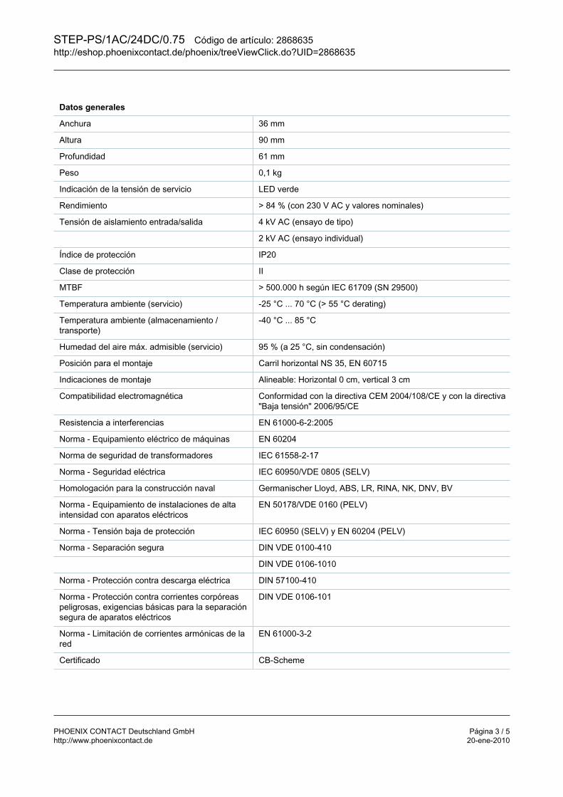
STEP-PS/1AC/24DC/0.75 Código de artículo: 2868635http://eshop.phoenixcontact.de/phoenix/treeViewClick.do?UID=2868635
PHOENIX CONTACT Deutschland GmbH Página 3 / 5http://www.phoenixcontact.de 20-ene-2010
Datos generales
Anchura 36 mm
Altura 90 mm
Profundidad 61 mm
Peso 0,1 kg
Indicación de la tensión de servicio LED verde
Rendimiento > 84 % (con 230 V AC y valores nominales)
Tensión de aislamiento entrada/salida 4 kV AC (ensayo de tipo)
2 kV AC (ensayo individual)
Índice de protección IP20
Clase de protección II
MTBF > 500.000 h según IEC 61709 (SN 29500)
Temperatura ambiente (servicio) -25 °C ... 70 °C (> 55 °C derating)
Temperatura ambiente (almacenamiento /transporte)
-40 °C ... 85 °C
Humedad del aire máx. admisible (servicio) 95 % (a 25 °C, sin condensación)
Posición para el montaje Carril horizontal NS 35, EN 60715
Indicaciones de montaje Alineable: Horizontal 0 cm, vertical 3 cm
Compatibilidad electromagnética Conformidad con la directiva CEM 2004/108/CE y con la directiva"Baja tensión" 2006/95/CE
Resistencia a interferencias EN 61000-6-2:2005
Norma - Equipamiento eléctrico de máquinas EN 60204
Norma de seguridad de transformadores IEC 61558-2-17
Norma - Seguridad eléctrica IEC 60950/VDE 0805 (SELV)
Homologación para la construcción naval Germanischer Lloyd, ABS, LR, RINA, NK, DNV, BV
Norma - Equipamiento de instalaciones de altaintensidad con aparatos eléctricos
EN 50178/VDE 0160 (PELV)
Norma - Tensión baja de protección IEC 60950 (SELV) y EN 60204 (PELV)
Norma - Separación segura DIN VDE 0100-410
DIN VDE 0106-1010
Norma - Protección contra descarga eléctrica DIN 57100-410
Norma - Protección contra corrientes corpóreaspeligrosas, exigencias básicas para la separaciónsegura de aparatos eléctricos
DIN VDE 0106-101
Norma - Limitación de corrientes armónicas de lared
EN 61000-3-2
Certificado CB-Scheme

STEP-PS/1AC/24DC/0.75 Código de artículo: 2868635http://eshop.phoenixcontact.de/phoenix/treeViewClick.do?UID=2868635
PHOENIX CONTACT Deutschland GmbH Página 4 / 5http://www.phoenixcontact.de 20-ene-2010
Homologaciones UL UL/C-UL Listed UL 508
UL/C-UL Recognized UL 60950
NEC Class 2 según UL 1310
UL Listed ANSI/ISA-12.12.01 Class I, Division 2, Groups A, B, C,D
Datos de conexión Entrada
Tipo de conexión Conexión por tornillo
Sección de conductor rígido mín. 0,2 mm²
Sección de conductor rígido máx. 2,5 mm²
Sección de conductor flexible mín. 0,2 mm²
Sección de conductor flexible máx. 2,5 mm²
Sección de conductor AWG/kcmil mín. 24
Sección de conductor AWG/kcmil máx. 12
Longitud a desaislar 6,5 mm
Rosca de tornillo M3
Datos de conexión Salida
Tipo de conexión Conexión por tornillo
Sección de conductor rígido mín. 0,2 mm²
Sección de conductor rígido máx. 2,5 mm²
Sección de conductor flexible mín. 0,2 mm²
Sección de conductor flexible máx. 2,5 mm²
Sección de conductor AWG/kcmil mín. 24
Sección de conductor AWG/kcmil máx. 12
Longitud a desaislar 6,5 mm
Señalización
Denominación Salida Indicación de estado LED
Indicación de estado LED "DC OK" verde
Observación acerca de la indicación de estado UOUT > 21,5 V: LED encendido
Dibujos
Esquema de conjunto
STEP-PS/1AC/24DC/0.75 Código de artículo: 2868635http://eshop.phoenixcontact.de/phoenix/treeViewClick.do?UID=2868635
PHOENIX CONTACT Deutschland GmbH Página 5 / 5http://www.phoenixcontact.de 20-ene-2010
Dirección
PHOENIX CONTACT Deutschland GmbHFlachsmarktstr. 832825 Blomberg,GermanyTel. +49 5235 3 12000Fax +49 5235 3 41200http://www.phoenixcontact.de
© 2010 Phoenix ContactReservado el derecho a efectuar modificaciones técnicas

GRUNDFOSCCCCCommerommerommerommerommercial Industrial Sercial Industrial Sercial Industrial Sercial Industrial Sercial Industrial Service Manualvice Manualvice Manualvice Manualvice Manual
CRN3Parts List & Kits
Contents
Parts ListSpare Part Kits
AccessoriesSpecial Tools
Standard ToolsTools for Torques
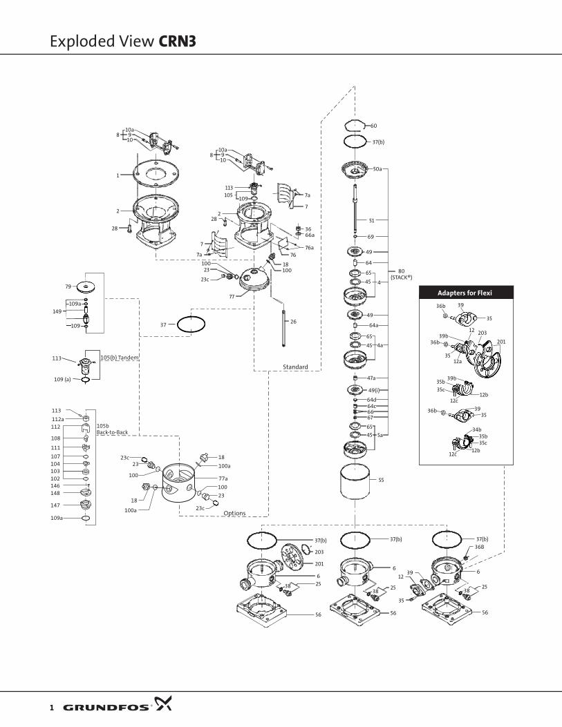
Exploded View CRN3
1
105(b) Tandem
Standard
Options
109 (a)
113
37
146
111
104
102
107
103
108
112
112a
113
148
147
109a
105bBack-to-Back
18
100a
77a
100
23
23c100a
2323c
100
18
109
149109a
79
56 56 56
3825
6
35
1239
6
37(b)
55
5a45
65
676664c64d
37(b)36B
382538 25
6
201
203
37(b)
49(i)
47a
4a45
65
64a
49
445
65 80(STACK®)
36b 39
35
39b
39b35b35c
12c12b
3935
34b35b35c
12b12c
36b
3512a
12 203
201
64
49
7a
7
3666a
76a76
18100
77
26
10a
1
2
28
10a
1098
910
8
113105
109
228
7
7a
10023
23c
36b
69
51
50a
37(b)
60
Adapters for Flexi
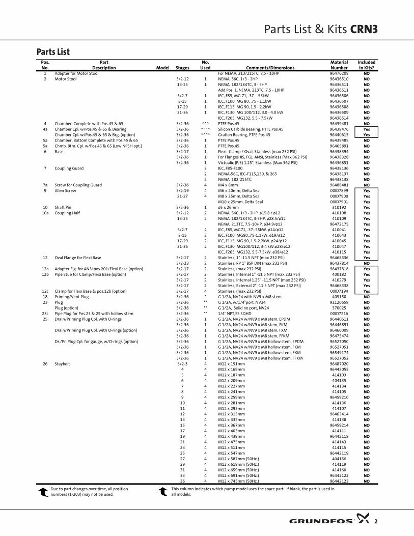
Parts List
Parts List & Kits CRN3
2
Pos. Part No. Material IncludedNo. Description Model Stages Used Comments/Dimensions Number in Kits?
1 Adapter for Motor Stool For NEMA, 213/215TC, 7.5 - 10HP 96476208 NO2 Motor Stool 3/2-12 1 NEMA, 56C, 1/3 - 2HP 96436510 NO
13-25 1 NEMA, 182/184TC, 3 - 5HP 96436511 NOAdd Pos. 1, NEMA, 213TC, 7.5 - 10HP 96436511 NO
3/2-7 1 IEC, F85, MG 71, .37 - .55kW 96436506 NO8-15 1 IEC, F100, MG 80, .75 - 1.1kW 96436507 NO
17-29 1 IEC, F115, MG 90, 1.5 - 2.2kW 96436508 NO31-36 1 IEC, F130, MG 100/112, 3.0 - 4.0 kW 96436509 NO
IEC, F265, MG132, 5.5 - 7.5kW 96436514 NO4 Chamber, Complete with Pos.45 & 65 3/2-36 ^^^ PTFE Pos.45 96439481 NO
4a Chamber Cpl. w/Pos.45 & 65 & Bearing 3/2-36 ^^^^ Silicon Carbide Bearing, PTFE Pos.45 96439476 YesChamber Cpl. w/Pos.45 & 65 & Brg. (option) 3/2-36 ^^^^ Graflon Bearing, PTFE Pos.45 96440615 Yes
5a Chamber, Bottom Complete with Pos.45 & 65 3/2-36 1 PTFE Pos.45 96439485 NO5a Chmb. Btm. Cpl. w/Pos.45 & 65 (Low NPSH opt.) 3/2-36 1 PTFE Pos.45 96465891 NO6 Base 3/2-17 1 Flexi -Clamp / Oval, Stainless (max 232 PSI) 96438394 NO
3/2-36 1 For Flanges JIS, FGJ, ANSI, Stainless (Max 362 PSI) 96438328 NO3/2-36 1 Victualic (PJE) 1.25", Stainless (Max 362 PSI) 96436851 NO
7 Coupling Guard 2 IEC, F85-F100 96438136 NO2 NEMA-56C, IEC-F115,130, & 265 96438137 NO2 NEMA, 182-215TC 96438138 NO
7a Screw for Coupling Guard 3/2-36 4 M4 x 8mm 96488481 NO9 Allen Screw 3/2-19 4 M6 x 20mm, Delta Seal 00ID7899 Yes
21-27 4 M8 x 25mm, Delta Seal 00ID7900 Yes M10 x 25mm, Delta Seal 00ID7901 Yes
10 Shaft Pin 3/2-36 1 ø5 x 26mm 310192 Yes10a Coupling Half 3/2-12 2 NEMA, 56C, 1/3 - 2HP. ø15.8 / ø12 410108 Yes
13-25 2 NEMA, 182/184TC, 3-5HP. ø28.5/ø12 410109 YesNEMA, 213TC, 7.5-10HP. ø34.9/ø12 96472175 Yes
3/2-7 2 IEC, F85, MG71, .37-.55kW. ø14/ø12 410041 Yes8-15 2 IEC, F100, MG80,.75-1.1kW. ø19/ø12 410043 Yes
17-29 2 IEC, F115, MG 90, 1.5-2.2kW. ø24/ø12 410045 Yes31-36 2 IEC, F130, MG100/112, 3-4 kW.ø28/ø12 410047 Yes
IEC, F265, MG132, 5.5-7.5kW. ø38/ø12 410115 Yes12 Oval Flange for Flexi Base 3/2-17 2 Stainless, 1" -11.5 NPT (max 232 PSI) 96468336 Yes
3/2-23 2 Stainless, RP 1" BSP DIN (max 232 PSI) 96437814 NO12a Adapter Flg. for ANSI pos.201/Flexi Base (option) 3/2-17 2 Stainless, (max 232 PSI) 96437818 Yes12b Pipe Stub for Clamp/Flexi Base (option) 3/2-17 2 Stainless, Internal 1" -11.5 NPT (max 232 PSI) 400182 Yes
3/2-17 2 Stainless, Internal 1.25" -11.5 NPT (max 232 PSI) 410279 Yes3/2-17 2 Stainless, External 2" -11.5 NPT (max 232 PSI) 96468338 Yes
12c Clamp for Flexi Base & pos.12b (option) 3/2-17 4 Stainless, (max 232 PSI) 00ID7194 Yes18 Priming/Vent Plug 3/2-36 * G 1/2A, NV24 with NV9 x M8 stem 405150 NO23 Plug 3/2-36 ** G 1/2A, w/1/4"port, NV24 91120659 NO
Plug (option) 3/2-36 ** G 1/2A, Solid no port, NV24 370025 NO23c Pipe Plug for Pos.23 & 25 with hollow stem 3/2-36 ** 1/4" NPT,SS SQHD 00ID7216 NO25 Drain/Priming Plug Cpl. with O-rings 3/2-36 1 G 1/2A, NV24 w/NV9 x M8 stem, EPDM 96440611 NO
3/2-36 1 G 1/2A, NV24 w/NV9 x M8 stem, FKM 96446891 NODrain/Priming Plug Cpl. with O-rings (option) 3/2-36 1 G 1/2A, NV24 w/NV9 x M8 stem, FXM 96460009 NO
3/2-36 1 G 1/2A, NV24 w/NV9 x M8 stem, FFKM 96475474 NODr./Pr. Plug Cpl. for gauge, w/O-rings (option) 3/2-36 1 G 1/2A, NV24 w/NV9 x M8 hollow stem, EPDM 96527050 NO
3/2-36 1 G 1/2A, NV24 w/NV9 x M8 hollow stem, FKM 96527051 NO3/2-36 1 G 1/2A, NV24 w/NV9 x M8 hollow stem, FXM 96549174 NO3/2-36 1 G 1/2A, NV24 w/NV9 x M8 hollow stem, FFKM 96527052 NO
26 Staybolt 3/2-3 4 M12 x 151mm 96487020 NO4 4 M12 x 169mm 96442055 NO5 4 M12 x 187mm 414103 NO6 4 M12 x 209mm 404135 NO7 4 M12 x 227mm 414134 NO8 4 M12 x 241mm 414105 NO9 4 M12 x 259mm 96459210 NO
10 4 M12 x 281mm 414136 NO11 4 M12 x 295mm 414107 NO12 4 M12 x 313mm 96463414 NO13 4 M12 x 335mm 414138 NO15 4 M12 x 367mm 96459214 NO17 4 M12 x 403mm 414111 NO19 4 M12 x 439mm 96442118 NO21 4 M12 x 475mm 414143 NO23 4 M12 x 511mm 414115 NO25 4 M12 x 547mm 96442119 NO27 4 M12 x 587mm (50Hz.) 404156 NO29 4 M12 x 619mm (50Hz.) 414119 NO31 4 M12 x 659mm (50Hz.) 414160 NO33 4 M12 x 691mm (50Hz.) 96442122 NO36 4 M12 x 745mm (50Hz.) 96442123 NO
Due to part changes over time, all positionnumbers (1-203) may not be used.
This column indicates which pump model uses the spare part. If blank, the part is used in all models.

Parts List
Parts List & Kits CRN3
3
Pos. Part No. Material IncludedNo. Description Model Stages Used Comments/Dimensions Number in Kits?26 Staybolt (Cool Top®, Back-to-Back 3/2-3 4 M12 x 263mm 404138 NO
& Tandem Seal option) 4 4 M12 x 281mm 414136 NO5 4 M12 x 295mm 414107 NO6 4 M12 x 317mm 404141 NO
7 4 M12 x 335mm 414138 NO 8 4 M12 x 349mm 414109 NO
9 4 M12 x 367mm 96459214 NO10 4 M12 x 385mm 96458503 NO11 4 M12 x 403mm 414111 NO12 4 M12 x 425mm 404147 NO13 4 M12 x 439mm 96442118 NO15 4 M12 x 475mm 414143 NO17 4 M12 x 511mm 414115 NO19 4 M12 x 547mm 96442119 NO21 4 M12 x 587mm 404156 NO23 4 M12 x 619mm 414119 NO25 4 M12 x 659mm 414160 NO27 4 M12 x 691mm (50Hz.) 96442122 NO29 4 M12 x 727mm (50Hz.) 96458505 NO31 4 M12 x 763mm (50Hz.) 96458506 NO33 4 M12 x 799mm (50Hz.) 414155 NO36 4 M12 x 853mm (50Hz.) 96458507 NO
28 Motor Bolt 3/2-19 4 NEMA, 56C, 1/3 - 2HP. UNC 3/8" x 25mm 00ID1839 NO21-27 4 NEMA, 182/184TC, 3 - 5HP.UNC1/2" x 25mm 00ID1840 NO
NEMA, 213TC, 7.5 -10HP. UNC 1/2" x 1.25" 91128631 NO3/2-11 4 IEC, F85, MG71, .37-.55kW. M6 x 20mm 00ID8022 NO12-23 4 IEC, F100, MG80,.75-1.1kW. M6 x 25mm 00ID8023 NO24-36 4 IEC, F115, MG 90, 1.5-2.2kW. M8 x 20mm 00ID8024 NO
IEC, F130, MG100/112, 3-4 kW. M8 x 25mm 00ID8025 NOIEC, F265, MG132, 5.5-7.5kW. M12 x 45mm 00ID7914 NO
35 Hexagon Head Screw for Oval "CI" Flange (Flexi option) 3/2-17 4 M10 x70mm, 8.8, A4, DIN931 96447227 YesHexagon Head Screw for Oval "N" Flange (Flexi option) 3/2-17 4 M10 x 60mm, A4, DIN931 96447228 Yes
35b Screw for Clamp Pos.12c (Flexi option) 3/2-17 4 M8 x 40mm - A2, RR DIN933 00ID7188 Yes35c Nut for Screw Pos.35b for Clamp Pos.12c (Flexi option) 3/2-17 4 M8, 304SS 00ID7187 Yes36 Staybolt Nut 3/2-36 4 19mm x M12, 316SS 00ID0876 NO
36b Nut for Screw Pos.35 Oval Flange (Flexi option) 3/2-17 4 M10, 316SS w/Delta Seal 96438757 Yes37 Sleeve O-ring 3/2-36 EPDM, ø137.5 x 3.3mm 96438743 Yes
3/2-36 FKM, ø137.5 x 3.3mm 96438744 Yes37b Sleeve O-ring (option) 3/2-36 FXM, ø137.5 x 3.3mm 96458109 Yes
Sleeve O-ring (option) 3/2-36 FFKM, ø136.12 x 3.53mm 96466718 Yes38 Drain Plug O-ring 3/2-36 1 EPDM, ø16.3 x 2.4mm 00ID1288 Yes
3/2-36 1 FKM, ø16.3 x 2.4mm 00ID2231 YesDrain Plug O-ring (option) 3/2-36 1 FFKM, ø16.3 x 2.4mm 96428162 YesDrain Plug O-ring (option) 3/2-36 1 FXM, ø16.3 x 2.4mm 96442869 Yes
39 Gasket for Oval Flange 3/2-17 2 95 x 55 x ø35 x 2mm, KLINGERSIL C4430 400189 Yes39b O-ring for Clamp,Thread stub-Union-& FGJ Flange (option) 3/2-17 2 EPDM, ø44.45 x 3.53mm 96407726 Yes
O-ring for Clamp,Thread stub-Union-& FGJ Flange (option) 3/2-17 2 FKM, ø44.45 x 3.53mm 96411713 Yes45 Neck Ring 3/2-36 # stgs ø41.3 x ø30.6 x .75mm, PTFE 400003 Yes
47a Bearing Ring/Spacer 3/2-36 ^^^^ SiC 150, ø17.37 x ø13.10 x ø10.9 x 13mm 96437488 YesBrg. Ring/Spacer (option for Graflon Pos. 4a) 3/2-36 ^^^^ TC, ø15.92 x ø13.10 x ø10.9 x 9.7mm 400041 Yes
49 Impeller 3/2-36 # stgs- ø73.6 x ø30.6 x 9.55mm (back-plate .5mm) 96433169 NO49i Impeller (Low NPSH option) 3/2-36 1 ø73.0 x ø35.0 x 13.2mm (back-plate 1.0mm) 96437503 NO50a Top Guide Vane 3-36 1 96457638 NO
Top Guide Vane Plate (option for destaging) 3/2 1 96478562 NO51 Shaft, Complete 3/2-3 1 ø12 x 160.5mm 96439607 NO
4 1 ø12 x 180.5mm 96440386 NO5 1 ø12 x 196.5mm 96440387 NO6 1 ø12 x 214.5mm 96440388 NO7 1 ø12 x 234.5mm 96440389 NO8 1 ø12 x 250.5mm 96440390 NO9 1 ø12 x 268.5mm 96440391 NO
10 1 ø12 x 288.5mm 96440392 NO11 1 ø12 x 304.5mm 96440393 NO12 1 ø12 x 322.5mm 96440394 NO13 1 ø12 x 342.5mm 96440395 NO15 1 ø12 x 376.5mm 96440396 NO17 1 ø12 x 412.5mm 96440398 NO19 1 ø12 x 450.5mm 96440400 NO21 1 ø12 x 484.5mm 96440401 NO23 1 ø12 x 520.5mm 96440403 NO25 1 ø12 x 556.5mm 96440405 NO27 1 ø12 x 592.5mm (50Hz.) 96440406 NO29 1 ø12 x 628.5mm (50Hz.) 96440407 NO31 1 ø12 x 664.5mm (50Hz.) 96440409 NO33 1 ø12 x 700.5mm (50Hz.) 96440410 NO36 1 ø12 x 754.5mm (50Hz.) 96440411 NO
51 Shaft, Cpl. (Cool Top®, Back-to-Back & Tandem Seal option) 3/2-3 1 ø12 x 265.5mm 96457560 NO4 1 ø12 x 285.5mm 96457561 NO5 1 ø12 x 301.5mm 96457562 NO
Due to part changes over time, all position numbers (1-203) may not be used.
This column indicates which pump model uses the spare part. If blank, the part is used in all models.
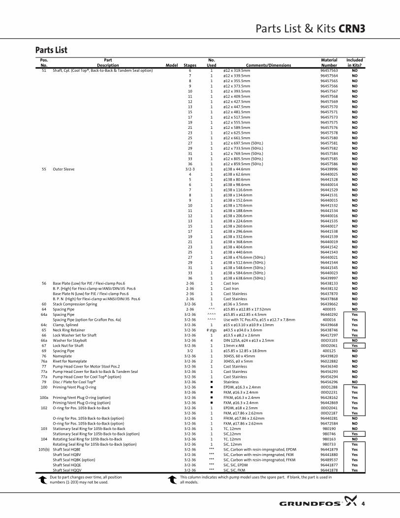
Parts List
Parts List & Kits CRN3
4
Pos. Part No. Material IncludedNo. Description Model Stages Used Comments/Dimensions Number in Kits?51 Shaft, Cpl. (Cool Top®, Back-to-Back & Tandem Seal option) 6 1 ø12 x 319.5mm 96457563 NO
7 1 ø12 x 339.5mm 96457564 NO8 1 ø12 x 355.5mm 96457565 NO9 1 ø12 x 373.5mm 96457566 NO
10 1 ø12 x 393.5mm 96457567 NO11 1 ø12 x 409.5mm 96457568 NO12 1 ø12 x 427.5mm 96457569 NO13 1 ø12 x 447.5mm 96457570 NO15 1 ø12 x 481.5mm 96457571 NO17 1 ø12 x 517.5mm 96457573 NO19 1 ø12 x 555.5mm 96457575 NO21 1 ø12 x 589.5mm 96457576 NO23 1 ø12 x 625.5mm 96457578 NO25 1 ø12 x 661.5mm 96457580 NO27 1 ø12 x 697.5mm (50Hz.) 96457581 NO29 1 ø12 x 733.5mm (50Hz.) 96457582 NO31 1 ø12 x 769.5mm (50Hz.) 96457584 NO33 1 ø12 x 805.5mm (50Hz.) 96457585 NO36 1 ø12 x 859.5mm (50Hz.) 96457586 NO
55 Outer Sleeve 3/2-3 1 ø138 x 44.6mm 96439996 NO4 1 ø138 x 62.6mm 96440025 NO5 1 ø138 x 80.6mm 96441528 NO6 1 ø138 x 98.6mm 96440014 NO7 1 ø138 x 116.6mm 96441529 NO8 1 ø138 x 134.6mm 96441531 NO9 1 ø138 x 152.6mm 96440015 NO
10 1 ø138 x 170.6mm 96441532 NO11 1 ø138 x 188.6mm 96441534 NO12 1 ø138 x 206.6mm 96440016 NO13 1 ø138 x 224.6mm 96441535 NO15 1 ø138 x 260.6mm 96440017 NO17 1 ø138 x 296.6mm 96441538 NO19 1 ø138 x 332.6mm 96441539 NO21 1 ø138 x 368.6mm 96440019 NO23 1 ø138 x 404.6mm 96441542 NO25 1 ø138 x 440.6mm 96441543 NO27 1 ø138 x 476.6mm (50Hz.) 96440021 NO29 1 ø138 x 512.6mm (50Hz.) 96441544 NO31 1 ø138 x 548.6mm (50Hz.) 96441545 NO33 1 ø138 x 584.6mm (50Hz.) 96440023 NO36 1 ø138 x 638.6mm (50Hz.) 96439997 NO
56 Base Plate (Low) for PJE / Flexi-clamp Pos.6 2-36 1 Cast Iron 96438133 NOB. P. (High) for Flexi-clamp w/ANSI/DIN/JIS Pos.6 2-36 1 Cast Iron 96438132 NOBase Plate N (Low) for PJE / Flexi-clamp Pos.6 2-36 1 Cast Stainless 96437870 NOB. P. N (High) for Flexi-clamp w/ANSI/DIN/JIS Pos.6 2-36 1 Cast Stainless 96437868 NO
60 Stack Compression Spring 3/2-36 1 ø136 x 3.5mm 96439662 NO64 Spacing Pipe 2-36 ^^^ ø15.85 x ø12.85 x 17.52mm 400035 NO
64a Spacing Pipe 3/2-36 ^^^^ ø15.85 x ø12.85 x 4.5mm 96440292 YesSpacing Pipe (option for Graflon Pos. 4a) 3/2-36 ^^^^ Use with TC Pos.47a, ø15 x ø12.7 x 7.8mm 400016 Yes
64c Clamp, Splined 3/2-36 1 ø15 x ø13.10 x ø10.9 x 13mm 96439668 Yes65 Neck Ring Retainer 3/2-36 # stgs ø43.5 x ø34.0 x 3.6mm 96438746 Yes66 Lock Washer Set for Shaft 3/2-36 1 ø13.5 x ø8.2 x 2.6mm 96417297 Yes
66a Washer for Staybolt 3/2-36 4 DIN 125A, ø24 x ø13 x 2.5mm 00ID3103 NO67 Lock Nut for Shaft 3/2-36 1 13mm x M8 00ID2061 Yes69 Spacing Pipe 3/2 1 ø15.85 x 12.85 x 18.0mm 400125 NO76 Nameplate 3/2-36 1 304SS, 60 x 45mm 96439820 NO
76a Rivet for Nameplate 3/2-36 2 304SS, ø3 x 5mm 96022882 NO77 Pump Head Cover for Motor Stool Pos.2 3/2-36 1 Cast Stainless 96436340 NO
77a Pump Head Cover for Back to Back & Tandem Seal 3/2-36 1 Cast Stainless 96456293 NO77a Pump Head Cover for Cool Top® (option) 3/2-36 1 Cast Stainless 96456294 NO79 Disc / Plate for Cool Top® 3/2-36 Stainless 96456296 NO
100 Priming/Vent Plug O-ring 3/2-36 EPDM, ø16.3 x 2.4mm 00ID1288 Yes3/2-36 FKM, ø16.3 x 2.4mm 00ID2231 Yes
100a Priming/Vent Plug O-ring (option) 3/2-36 FFKM, ø16.3 x 2.4mm 96428162 YesPriming/Vent Plug O-ring (option) 3/2-36 FXM, ø16.3 x 2.4mm 96442869 Yes
102 O-ring for Pos. 105b Back-to-Back 3/2-36 1 EPDM, ø18 x 2.5mm 00ID2041 Yes3/2-36 1 FKM, ø17.86 x 2.62mm 00ID2187 Yes
O-ring for Pos. 105b Back-to-Back (option) 3/2-36 1 FFKM, ø17.86 x 2.62mm 96440281 NOO-ring for Pos. 105b Back-to-Back (option) 3/2-36 1 FXM, ø17.86 x 2.62mm 96472584 NO
103 Stationary Seal Ring for 105b Back-to-Back 3/2-36 1 TC, 12mm 980190 NOStationary Seal Ring for 105b Back-to-Back (option) 3/2-36 1 SiC,12mm 980746 Yes
104 Rotating Seal Ring for 105b Back-to-Back 3/2-36 1 TC, 12mm 980163 NORotating Seal Ring for 105b Back-to-Back (option) 3/2-36 1 SiC, 12mm 980733 Yes
105(b) Shaft Seal HQBE 3/2-36 *** SiC, Carbon with resin-impregnated, EPDM 96441879 YesShaft Seal HQBV 3/2-36 *** SiC, Carbon with resin-impregnated, FKM 96441880 Yes
Shaft Seal HQBK (option) 3/2-36 *** SiC, Carbon with resin-impregnated, FFKM 96489537 YesShaft Seal HQQE 3/2-36 *** SiC, SiC, EPDM 96441877 YesShaft Seal HQQV 3/2-36 *** SiC, SiC, FKM 96441878 Yes
Due to part changes over time, all position numbers (1-203) may not be used.
This column indicates which pump model uses the spare part. If blank, the part is used in all models.

Parts List
Parts List & Kits CRN3
5
Pos. Part No. Material IncludedNo. Description Model Stages Used Comments/Dimensions Number in Kits?
105(b) Shaft Seal HQQF (option) 3/2-36 *** SiC, SiC, FXM 96472620 YesShaft Seal HQQK (option) 3/2-36 *** SiC, SiC, FFKM 96464381 YesShaft Seal HUBE 3/2-36 *** TC, Carbon with resin-impregnated, EPDM 96441873 YesShaft Seal HUBV 3/2-36 *** TC, Carbon with resin-impregnated, FKM 96441874 YesShaft Seal HUBF (option) 3/2-36 *** TC, Carbon with resin-impregnated, FXM 96481464 YesShaft Seal HUBK (option) 3/2-36 *** TC, Carbon with resin-impregnated, FFKM 96481463 YesShaft Seal HUUE 3/2-36 *** TC, TC, EPDM 96441875 YesShaft Seal HUUV 3/2-36 *** TC, TC, FKM 96441876 YesShaft Seal HUUF (option) 3/2-36 *** TC, TC, FXM 96475542 YesShaft Seal HUUK (option) 3/2-36 *** TC, TC, FFKM 96467885 Yes
105b Shaft Seal/inboard for Back-to-Back OQQE 3/2-36 1 SiC, SiC, EPDM 985200 YesShaft Seal/inboard for Back-to-Back OQQV 3/2-36 1 SiC, SiC, FKM 985760 YesShaft Seal/inboard for Back-to-Back OUUE 3/2-36 1 TC, TC, EPDM 985189 NOShaft Seal/inboard for Back-to-Back OUUV 3/2-36 1 TC, TC, FKM 985190 NO
107 O-ring for Pos. 105b Back-to-Back 3/2-36 1 EPDM, ø11.5 x 4.3mm 00ID2040 Yes3/2-36 1 FKM, ø11.5 x 4.3mm 00ID2186 Yes
O-ring for Pos. 105b Back-to-Back (option) 3/2-36 1 FFKM, ø11.5 x 4.3mm 96440282 NOO-ring for Pos. 105b Back-to-Back (option) 3/2-36 1 FXM, ø11.5 x 3.18mm 96472618 NO
108 Spring for Pos. 105b Back-to-Back 3/2-36 1 12mm 980195 Yes109(a) O-ring for Shaft Seal Pos.105 3/2-36 1 EPDM, ø21.3 x 3.0mm 00ID1798 Yes
3/2-36 1 FKM, ø21.2 x 3.0mm 00ID2339 Yes109b O-ring for Shaft Seal Pos. 105 (option) 3/2-36 1 FXM, ø22 x 2.75mm 96458111 Yes
O-ring for Shaft Seal Pos. 105 (option) 3/2-36 1 FFKM, ø23.47 x 2.62mm 96464384 Yes111 Seal Driver (small) for Pos. 105b Back-to-Back 3/2-36 1 980192 Yes112 Seal Driver (large) for Pos. 105b Back-to-Back 3/2-36 1 980191 Yes
112a Seal Drv threaded for 112, Pos. 105b Back-to-Back 3/2-36 1 400203 Yes113 Set Screw for 112a, for Pos. 105b Back-to-Back 3/2-36 1 3mm x M5 x 6mm 00ID7392 Yes117 Pipe for Air Vent (option) 3/2-36 1 R 1/2", 316 Stainless 330272 Yes118 Automatic Air Vent (option) 3/2-36 1 Type AE50S 1/2" BSP, Stainless 96498508 Yes146 Allen Bolt for 147/148, for Pos. 105b Back-to-Back 3/2-36 1 2.5mm x M3 x 5mm 96462639 Yes147 Stationary Seal Retainer - Pos. 105b Back-to-Back 3/2-36 1 NV36, 316SS 96457354 NO148 Seal Retainer Washer - Pos. 105b Back-to-Back 3/2-36 1 316SS, ø36.0 x ø21.6 x 5.0mm 96457355 NO149 Connecting Pipe for Cool Top® 3/2-36 1 NV36, 316SS, FXM & EPDM 96460414 NO
3/2-36 1 NV36, 316SS, FXM & FKM 96460415 NO201 Flange 3/2-36 1 ANSI, DIN, JIS PN40/30K, Cast Iron 96439203 Yes
3/2-36 1 ANSI, DIN, JIS PN40/30K, Stainless 96439492 Yes203 Lock Ring for Flange 3/2-36 1 Stainless 96439718 Yes
NOTES: Key to Symbols^^^ 3/2 to 9 stage= # of Stages less 2 KITS ....... Recommended spare part
10 to 19 stage= # of stages less 3 Ø ....... Diameter21 to 27 stage = # of stages less 4 ANSI ....... American National Standards Institute29 to 36 stage = # of stages less 5 CPL ....... Complete Assembly – these parts consist of more than one component
EPDM ....... Ethylene Propylene (also known as EPR and EPT) – an elastic^^^^ 3/2 to 9 stage= use 1 substance similar to rubber
10 to 19 stage= use2 FFKM ....... Kalrez Elastomer made by DuPont21 to 27 stage = use 3 FKM ....... Fluoro Elastomer (generic for Viton)29 to 36 stage = use 4 FXM ....... Fluoraz Elastomer made by Greene Tweed
M ....... International standard thread size designation (thread diameter in mm)* Standard use 1. Back-to-Back or Tandem pump version use 3 mm ....... Millimeter** Standard use 1. Back-to-Back or Tandem pump version use 3 MG ....... Identifies Grundfos motor type/size*** 1 used in Hxxx (Standard), 2 used in Pxxx (Tandem) pump version N ....... Stainless
NBR ....... Buna - N (also known as Nitrile) – an elastic substance similar to rubber# stgs- Use the number of stages in standard models, NEMA ....... National Electrical Manufacturers Association
less one in de-staged and Low NPSH models PTFE ....... TeflonSiC ....... Silicon Carbide
Standard use 2. Back-to-Back or Tandem pump version use 3 TC ....... Tungsten CarbideUNC ....... Unified National Coarse – a standard for threads on bolts
Standard use 2. Back-to-Back or Tandem pump version use 6
Cool Top® is a registered trademark of Grundfos Pumps
Due to part changes over time, all position numbers (1-203) may not be used.
This column indicates which pump model uses the spare part. If blank, the part is used in all models.
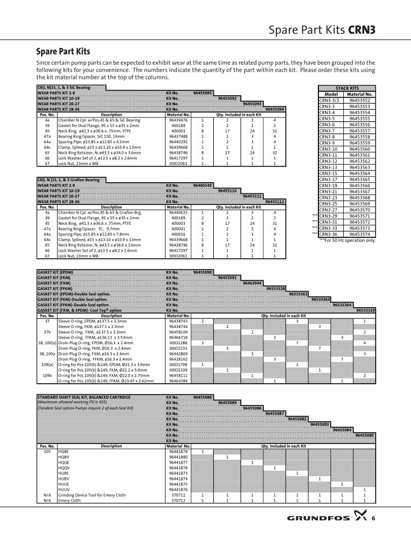
Spare Part KitsSince certain pump parts can be expected to exhibit wear at the same time as related pump parts, they have been grouped into thefollowing kits for your convenience. The numbers indicate the quantity of the part within each kit. Please order these kits usingthe kit material number at the top of the columns.
Spare Part Kits CRN3
6
STACK KITSModel Material No.
CRN3-3/2 96453552CRN3-3 96453553CRN3-4 96453554CRN3-5 96453555CRN3-6 96453556CRN3-7 96453557CRN3-8 96453558CRN3-9 96453559CRN3-10 96453560CRN3-11 96453561CRN3-12 96453562CRN3-13 96453563CRN3-15 96453564CRN3-17 96453565CRN3-19 96453566CRN3-21 96453567CRN3-23 96453568CRN3-25 96453569CRN3-27 96453570
*** CRN3-29 96453571*** CRN3-31 96453572*** CRN3-33 96453573*** CRN3-36 96453574
***For 50 Hz operation only.
CR(I, N)1S, 1, & 3 SiC BearingWEAR PARTS KIT 2-9 Kit No. 96455095WEAR PARTS KIT 10-19 Kit No. 96455092WEAR PARTS KIT 20-27 Kit No. 96455093WEAR PARTS KIT 28-36 Kit No. 96455094
Pos. No. Description Material No. Qty. Included in each Kit4a Chamber N Cpl. w/Pos.45 & 65 & SiC Bearing 96439476 1 2 3 439 Gasket for Oval Flange, 95 x 55 x ø35 x 2mm 400189 2 2 2 245 Neck Ring, ø41.3 x ø30.6 x .75mm, PTFE 400003 8 17 24 32
47a Bearing Ring/Spacer, SiC 150, 13mm 96437488 1 2 3 464a Spacing Pipe, ø15.85 x ø12.85 x 4.5mm 96440292 1 2 3 464c Clamp, Splined, ø15 x ø13.10 x ø10.9 x 13mm 96439668 1 1 1 165 Neck Ring Retainer, N, ø43.5 x ø34.0 x 3.6mm 96438746 8 17 24 3266 Lock Washer Set of 2, ø13.5 x ø8.2 x 2.6mm 96417297 1 1 1 167 Lock Nut, 13mm x M8 00ID2061 1 1 1 1
CR(I, N )1S, 1, & 3 Graflon BearingWEAR PARTS KIT 2-9 Kit No. 96460140WEAR PARTS KIT 10-19 Kit No. 96455110WEAR PARTS KIT 20-27 Kit No. 96455111WEAR PARTS KIT 28-36 Kit No. 96455112
Pos. No. Description Material No. Qty. Included in each Kit4a Chamber N Cpl. w/Pos.45 & 65 & Graflon Brg. 96440615 1 2 3 439 Gasket for Oval Flange, 95 x 55 x ø35 x 2mm 400189 2 2 2 245 Neck Ring, ø41.3 x ø30.6 x .75mm, PTFE 400003 8 17 24 32
47a Bearing Ring/Spacer, TC, 9.7mm 400041 1 2 3 464a Spacing Pipe, ø15.85 x ø12.85 x 7.8mm 400016 1 2 3 464c Clamp, Splined, ø15 x ø13.10 x ø10.9 x 13mm 96439668 1 1 1 165 Neck Ring Retainer, N, ø43.5 x ø34.0 x 3.6mm 96438746 8 17 24 3266 Lock Washer Set of 2, ø13.5 x ø8.2 x 2.6mm 96417297 1 1 1 167 Lock Nut, 13mm x M8 00ID2061 1 1 1 1
GASKET KIT (EPDM) Kit No. 96455090GASKET KIT (FKM) Kit No. 96455091GASKET KIT (FXM) Kit No. 96463944GASKET KIT (FFKM) Kit No. 96533328GASKET KIT (EPDM)-Double Seal option. Kit No. 96533362GASKET KIT (FKM)-Double Seal option. Kit No. 96533363GASKET KIT (FFKM)-Double Seal option. Kit No. 96533364GASKET KIT (FXM, & EPDM)- Cool Top® option Kit No. 96533329
Pos. No. Description Material No. Qty. Included in each Kit37 Sleeve O-ring, EPDM, ø137.5 x 3.3mm 96438743 2 3 1
Sleeve O-ring, FKM, ø137.5 x 3.3mm 96438744 2 337b Sleeve O-ring, FXM, ø137.5 x 3.3mm 96458109 2 2
Sleeve O-ring, FFKM, ø136.12 x 3.53mm 96466718 2 338, 100(a) Drain Plug O-ring, EPDM, Ø16.3 x 2.4mm 00ID1288 3 7 4
Drain Plug O-ring, FKM, Ø16.3 x 2.4mm 00ID2231 3 738, 100a Drain Plug O-ring, FXM, ø16.3 x 2.4mm 96442869 3 3
Drain Plug O-ring, FFKM, ø16.3 x 2.4mm 96428162 3 7109(a) O-ring for Pos.105(b) &149, EPDM, Ø21.3 x 3.0mm 00ID1798 1 1
O-ring for Pos.105(b) &149, FKM, Ø21.2 x 3.0mm 00ID2339 1 1109b O-ring for Pos.105(b) &149, FXM, Ø22.0 x 2.75mm 96458111 1 2
O-ring for Pos.105(b) &149, FFKM, Ø23.47 x 2.62mm 96464384 1 2
STANDARD SHAFT SEAL KIT, BALANCED CARTRIDGE Kit No. 96455088(Maximum allowed working PSI is 435) Kit No. 96455089(Tandem Seal option Pumps require 2 of each Seal Kit) Kit No. 96455086
Kit No. 96455087Kit No. 96455082Kit No. 96455083Kit No. 96455084Kit No. 96455085Kit No.
Pos. No. Material No. Qty. Included in each Kit105 HQBE 96441879 1
HQBV 96441880 1 HQQE 96441877 1 HQQV 96441878 1HUBE 96441873 1HUBV 96441874 1HUUE 96441875 1HUUV 96441876 1
N/A Grinding Device Tool for Emery Cloth 370711 1 1 1 1 1 1 1 1N/A Emery Cloth 370712 1 1 1 1 1 1 1 1
Description
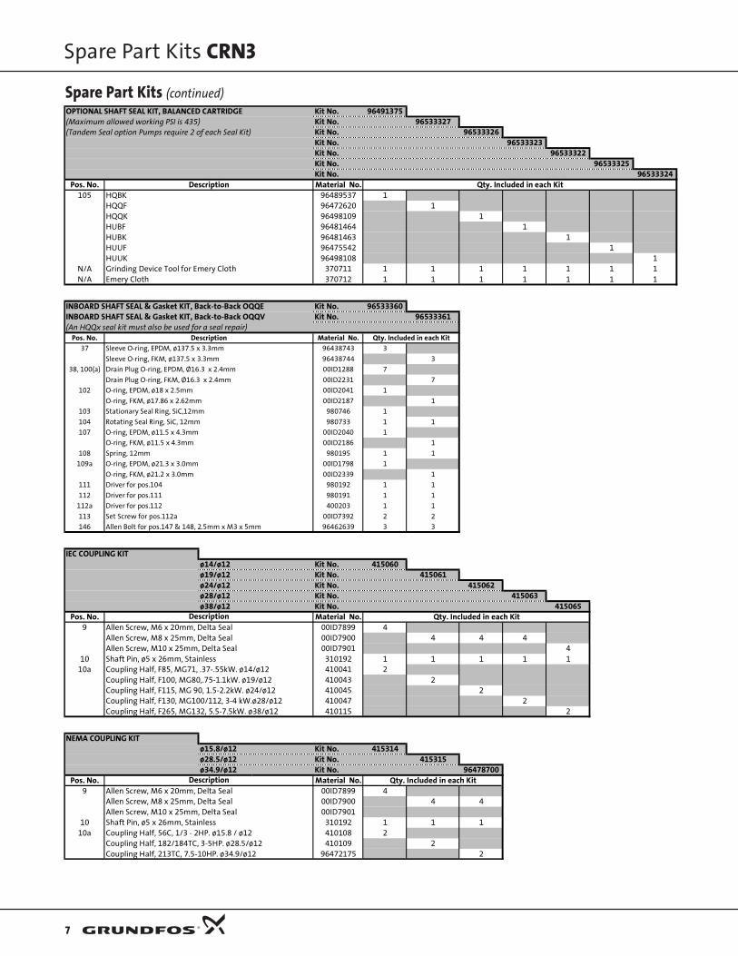
Spare Part Kits (continued)
Spare Part Kits CRN3
7
OPTIONAL SHAFT SEAL KIT, BALANCED CARTRIDGE Kit No. 96491375(Maximum allowed working PSI is 435) Kit No. 96533327(Tandem Seal option Pumps require 2 of each Seal Kit) Kit No. 96533326
Kit No. 96533323Kit No. 96533322Kit No. 96533325Kit No. 96533324
Pos. No. Description Material No. Qty. Included in each Kit105 HQBK 96489537 1
HQQF 96472620 1HQQK 96498109 1HUBF 96481464 1HUBK 96481463 1HUUF 96475542 1HUUK 96498108 1
N/A Grinding Device Tool for Emery Cloth 370711 1 1 1 1 1 1 1N/A Emery Cloth 370712 1 1 1 1 1 1 1
INBOARD SHAFT SEAL & Gasket KIT, Back-to-Back OQQE Kit No. 96533360INBOARD SHAFT SEAL & Gasket KIT, Back-to-Back OQQV Kit No. 96533361(An HQQx seal kit must also be used for a seal repair)
Pos. No. Description Material No. Qty. Included in each Kit37 Sleeve O-ring, EPDM, ø137.5 x 3.3mm 96438743 3
Sleeve O-ring, FKM, ø137.5 x 3.3mm 96438744 3
38, 100(a) Drain Plug O-ring, EPDM, Ø16.3 x 2.4mm 00ID1288 7
Drain Plug O-ring, FKM, Ø16.3 x 2.4mm 00ID2231 7
102 O-ring, EPDM, ø18 x 2.5mm 00ID2041 1
O-ring, FKM, ø17.86 x 2.62mm 00ID2187 1
103 Stationary Seal Ring, SiC,12mm 980746 1
104 Rotating Seal Ring, SiC, 12mm 980733 1 1
107 O-ring, EPDM, ø11.5 x 4.3mm 00ID2040 1
O-ring, FKM, ø11.5 x 4.3mm 00ID2186 1
108 Spring, 12mm 980195 1 1
109a O-ring, EPDM, ø21.3 x 3.0mm 00ID1798 1
O-ring, FKM, ø21.2 x 3.0mm 00ID2339 1
111 Driver for pos.104 980192 1 1
112 Driver for pos.111 980191 1 1
112a Driver for pos.112 400203 1 1
113 Set Screw for pos.112a 00ID7392 2 2
146 Allen Bolt for pos.147 & 148, 2.5mm x M3 x 5mm 96462639 3 3
IEC COUPLING KITø14/ø12 Kit No. 415060ø19/ø12 Kit No. 415061ø24/ø12 Kit No. 415062ø28/ø12 Kit No. 415063ø38/ø12 Kit No. 415065
Pos. No. Material No. Qty. Included in each Kit9 Allen Screw, M6 x 20mm, Delta Seal 00ID7899 4
Allen Screw, M8 x 25mm, Delta Seal 00ID7900 4 4 4Allen Screw, M10 x 25mm, Delta Seal 00ID7901 4
10 Shaft Pin, ø5 x 26mm, Stainless 310192 1 1 1 1 110a Coupling Half, F85, MG71, .37-.55kW. ø14/ø12 410041 2
Coupling Half, F100, MG80,.75-1.1kW. ø19/ø12 410043 2Coupling Half, F115, MG 90, 1.5-2.2kW. ø24/ø12 410045 2Coupling Half, F130, MG100/112, 3-4 kW.ø28/ø12 410047 2Coupling Half, F265, MG132, 5.5-7.5kW. ø38/ø12 410115 2
NEMA COUPLING KITø15.8/ø12 Kit No. 415314ø28.5/ø12 Kit No. 415315ø34.9/ø12 Kit No. 96478700
Pos. No. Material No. Qty. Included in each Kit9 Allen Screw, M6 x 20mm, Delta Seal 00ID7899 4
Allen Screw, M8 x 25mm, Delta Seal 00ID7900 4 4Allen Screw, M10 x 25mm, Delta Seal 00ID7901
10 Shaft Pin, ø5 x 26mm, Stainless 310192 1 1 110a Coupling Half, 56C, 1/3 - 2HP. ø15.8 / ø12 410108 2
Coupling Half, 182/184TC, 3-5HP. ø28.5/ø12 410109 2Coupling Half, 213TC, 7.5-10HP. ø34.9/ø12 96472175 2
Description
Description

FLEXI FLANGE KIT FOR SMALL CRI1S, 1, & 31" Threaded Stainless ( 232 PSI Max.) Kit No. 964680850
Pos. No. Material No. Qty. Included in each Kit12 Flange, Stainless, 1" - 11.5 NPT 96468336 235 Hex Head Bolt, M10 x 60mm, A4, DIN931 96447228 4
36b Nut, M10, 316SS w/Delta Seal 96438757 439 Gasket , 95 x 55 x ø35 x 2mm, KLINGERSIL C4430 400189 2
FLEXI FLANGE KIT FOR SMALL CRI1S, 1, 3, & 51-1/4" Threaded Stainless ( 232 PSI Max.) Kit No. 96480851
Pos. No. Material No. Qty. Included in each Kit12 Flange, Stainless, 1" - 11.5 NPT 96468337 235 Hex Head Bolt, M10 x 60mm, A4, DIN931 96447228 4
36b Nut, M10, 316SS w/Delta Seal 96438757 439 Gasket , 95 x 55 x ø35 x 2mm, KLINGERSIL C4430 400189 2
FLEXI CLAMP FLANGE KIT FOR SMALL CRI1S, 1, 3, & 51-1/4" Stainless Flange EPDM Kit No. 96480858(Conversion max. allowable operating pressure 232 ) FKM Kit No. 96480859
Pos. No. Material No. Qty. Included in each Kit12a Adapter Flg. for ANSI pos.201/Flexi Base (232 PSI) 96437818 2 235 Hex Head Bolt, M10 x 60mm, A4, DIN931 96447228 4 4
36b Nut, M10, 316SS w/Delta Seal 96438757 4 439b O-ring, EPDM, ø44.45 x 3.53mm 96407726 2
O-ring, FKM, ø44.45 x 3.53mm 96411713 2201 Flange, ANSI, DIN, JIS PN40/30K, Stainless 96439492 2 2203 Lock Ring, Stainless 96439718 2 2
FLEXI CLAMP KIT FOR SMALL CRI1S, 1, & 31" Internal Threaded SS Pipe Stub ( 232 PSI Max.) EPDM Kit No. 96480854
FKM Kit No. 96480855Pos. No. Material No. Qty. Included in each Kit
12b Stainless, Internal 1" -11.5 NPT 400182 2 212c Clamp for Flexi Base & pos.12b 00ID7194 4 435b Screw for Pos. 12c, M8 x 40mm - A2, RR DIN933 00ID7188 4 435c Nut for Pos. 35b, M8, 304SS 00ID7187 4 439b O-ring, EPDM, ø44.45 x 3.53mm 96407726 2
O-ring, FKM, ø44.45 x 3.53mm 96411713 2
FLEXI CLAMP KIT FOR SMALL CRI1S, 1, 3, & 51-1/4" Internal Threaded SS Pipe Stub ( 232 PSI Max.) EPDM Kit No. 96480856
FKM Kit No. 96480857Pos. No. Material No. Qty. Included in each Kit
12b Stainless, Internal 1-1/4" -11.5 NPT 410279 2 212c Clamp for Flexi Base & pos.12b 00ID7194 4 435b Screw for Pos. 12c, M8 x 40mm - A2, RR DIN933 00ID7188 4 435c Nut for Pos. 35b, M8, 304SS 00ID7187 4 439b O-ring, EPDM, ø44.45 x 3.53mm 96407726 2
O-ring, FKM, ø44.45 x 3.53mm 96411713 2
FLEXI CLAMP KIT FOR SMALL CRI1S, 1, 3, & 52" External Threaded SS Pipe Stub ( 232 PSI Max.) EPDM Kit No. 96480852
FKM Kit No. 96480853Pos. No. Material No. Qty. Included in each Kit
12b Stainless, Internal 2" -11.5 NPT 96468338 2 212c Clamp for Flexi Base & pos.12b 00ID7194 4 435b Screw for Pos. 12c, M8 x 40mm - A2, RR DIN933 00ID7188 4 435c Nut for Pos. 35b, M8, 304SS 00ID7187 4 439b O-ring, EPDM, ø44.45 x 3.53mm 96407726 2
O-ring, FKM, ø44.45 x 3.53mm 96411713 2
AIR VENT FOR SMALL CRKit No. 91128708
Pos. No. Material No. Qty. Included in each Kit117 Pipe for Air Vent, R1/2" , 316SS 330272 1118 Automatic Air Vent, Type AE50S 1/2" BSP, SS. 96498508 1
AccessoriesANSI COMPANION FLANGES FOR SMALL CR1-1/4" Threaded Stainless, 300 Lb. Class Kit No. 91129013
Pos. No. Material No. Qty. Included in each KitN/A Nut, HEX 5/8"-11 UNC, 18-8SS 0ID00164 8N/A Bolt, HEX 5/8" x 2-3/4", UNC 18-8SS 00ID7241 8N/A Flange 1-1/4" Stainless, ANSI, DIN, JIS PN40/30K, 00ID7239 2N/A Gasket Full Face Flange, 1-1/4", 300#, Cut Ring 400201 2
VICTAULIC TYPE COMPANION CONNECTIONS FOR SMALL CRI(N)EPDM Kit No. 4013010FKM Kit No. 0ID00118
Pos. No. Material No. Qty. Included in each KitN/A Victaulic Type Coupling, 1-1/4", EPDM 0ID17810 2N/A Victaulic Type Coupling, 1-1/4", 77 FKM 0ID00112 2N/A 1-1/4" Stainless NPT Nipple 4000011 2 2
Description
Description
Description
Description
Description
Description
Description
Description
Description
Spare Part Kits (continued)
Spare Part Kits • Accessories CRN3
8
Accessories
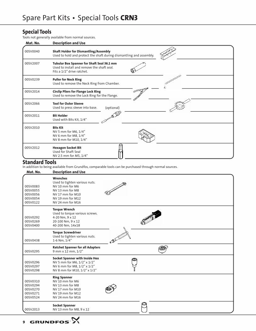
Spare Part Kits • Special Tools CRN3
9
Mat. No. Description and Use
00SV0040 Shaft Holder for Dismantling/AssemblyUsed to hold and protect the shaft during dismantling and assembly.
00SV2007 Tubular Box Spanner for Shaft Seal 36.1 mmUsed to install and remove the shaft seal.Fits a 1/2” drive ratchet.
00SV0239 Puller for Neck RingUsed to remove the Neck Ring from Chamber.
00SV2014 Circlip Pliers for Flange Lock RingUsed to remove the Lock Ring for the Flange.
00SV2066 Tool for Outer SleeveUsed to press sleeve into base.
00SV2011 Bit HolderUsed with Bits Kit, 1/4”
00SV2010 Bits KitNV 5 mm for M6, 1/4”NV 6 mm for M8, 1/4”NV 8 mm for M10, 1/4”
00SV2012 Hexagon Socket BitUsed for Shaft SealNV 2.5 mm for M5, 1/4”
Mat. No. Description and Use
WrenchesUsed to tighten various nuts.
00SV0083 NV 10 mm for M600SV0055 NV 13 mm for M800SV0056 NV 17 mm for M1000SV0054 NV 19 mm for M1200SV0122 NV 24 mm for M16
Torque WrenchUsed to torque various screws.
00SV0292 4-20 Nm, 9 x 1200SV0269 20-100 Nm, 9 x 1200SV0400 40-200 Nm, 14x18
Torque ScrewdriverUsed to tighten various nuts.
00SV0438 1-6 Nm, 1/4”
Ratchet Spanner for all Adapters00SV0295 9 mm x 12 mm, 1/2”
Socket Spanner with Inside Hex00SV0296 NV 5 mm for M6, 1/2” x 1/2”00SV0297 NV 6 mm for M8, 1/2” x 1/2”00SV0298 NV 8 mm for M10, 1/2” x 1/2”
Ring Spanner00SV0310 NV 10 mm for M600SV0294 NV 13 mm for M800SV0270 NV 17 mm for M1000SV0271 NV 19 mm for M1200SV0524 NV 24 mm for M16
Socket Spanner00SV2013 NV 13 mm for M8, 9 x 12
Special ToolsTools not generally available from normal sources.
Standard ToolsIn addition to being available from Grundfos, comparable tools can be purchased through normal sources.
(optional)

Being responsible is our foundationThinking ahead makes it possible
Innovation is the essence
L-CR-SM-031 05/04PRINTED IN USA
GRUNDFOS Pumps Corporation17100 W. 118th TerraceOlathe, Kansas 66062Phone: 913.227.3400Fax: 913.227.3500
www.grundfos.com
Being responsible is our foundationThinking ahead makes it possible
Innovation is the essence
GRUNDFOS Canada, Inc.2941 Brighton RoadOakville, Ontario L6H 6C9 CanadaPhone: 905.829.9533Fax: 905.829.9512
Bombas GRUNDFOS de Mexico S.A. de C.V.Boulevard TLC No. 15Parque Industrial Stiva AeropuertoApodaca, N.L. Mexico 66600Phone: 52.81.8144.4000Fax: 52.81.8144.4010
Subject to alterations.
CR, CRI, CRN, CRT
GRUNDFOS INSTRUCTIONS
Installation and operating instructions
Grundfos.bk Page 1 Wednesday, March 18, 2009 10:38 AM

2
LIMITED WARRANTYProducts manufactured by GRUNDFOS PUMPS CORPORATION (Grundfos) are warranted to the original user only to be free of defects in material and workmanship for a period of 24 months from date of installation, but not more than 30 months from date of manufacture. Grundfos' liability under this warranty shall be limited to repairing or replacing at Grundfos' option, without charge, F.O.B. Grundfos' factory or authorized service station, any product of Grundfos' manufacture. Grundfos will not be liable for any costs of removal, installation, transportation, or any other charges which may arise in connection with a warranty claim. Products which are sold but not manufactured by Grundfos are subject to the warranty provided by the manufacturer of said products and not by Grundfos' warranty. Grundfos will not be liable for damage or wear to products caused by abnormal operating conditions, accident, abuse, misuse, unauthorized alteration or repair, or if the product was not installed in accordance with Grundfos' printed installation and operating instructions.
To obtain service under this warranty, the defective product must be returned to the distributor or dealer of Grundfos' products from which it was purchased together with proof of purchase and installation date, failure date, and supporting installation data. Unless otherwise provided, the distributor or dealer will contact Grundfos or an authorized service station for instructions. Any defective product to be returned to Grundfos or a service station must be sent freight prepaid; documentation supporting the warranty claim and/or a Return Material Authorization must be included if so instructed.
GRUNDFOS WILL NOT BE LIABLE FOR ANY INCIDENTAL OR CONSEQUENTIAL DAMAGES, LOSSES, OR EXPENSES ARISING FROM INSTALLATION, USE, OR ANY OTHER CAUSES. THERE ARE NO EXPRESS OR IMPLIED WARRANTIES, INCLUDING MERCHANTABILITY OR FITNESS FOR A PARTICULAR PURPOSE, WHICH EXTEND BEYOND THOSE WARRANTIES DESCRIBED OR REFERRED TO ABOVE.
Some jurisdictions do not allow the exclusion or limitation of incidental or consequential damages and some jurisdictions do not allow limit actions on how long implied warranties may last. Therefore, the above limitations or exclusions may not apply to you. This warranty gives you specific legal rights and you may also have other rights which vary from jurisdiction to jurisdiction.
Grundfos.bk Page 2 Wednesday, March 18, 2009 10:38 AM

3
CR, CRI, CRN, CRTInstallation and operating instructions 5
Notice d'installation et de fonctionnement ?
Instrucciones de instalación y funcionamiento ?
Grundfos.bk Page 3 Wednesday, March 18, 2009 10:38 AM

4
Grundfos.bk Page 4 Wednesday, March 18, 2009 10:38 AM
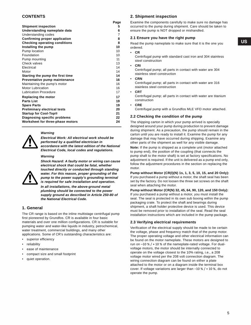
Grundfos.bk Page 5 Wednesday, March 18, 2009 10:38 AM
CONTENTSPage
Shipment inspection 5Understanding nameplate data 6Understanding codes 7Confirming proper application 8Checking operating conditions 8Installing the pump 10Pump location 10Foundation 10Pump mounting 11Check valves 13Electrical 14Motor 14Starting the pump the first time 14Preventative pump maintenance 16Maintaining the pump’s motor 16Motor Lubrication 16Lubrication Procedure 17Replacing the motor 17Parts List 19Spare Parts 19Preliminary electrical tests 20Startup for Cool-Top® 21Diagnosing specific problems 22Worksheet for three-phase motors 24
1. GeneralThe CR range is based on the inline multistage centrifugal pump first pioneered by Grundfos. CR is available in four basicmaterials and over one million configurations. CR is suitable for pumping water and water-like liquids in industry, petrochemical, water treatment, commercial buildings, and many otherapplications. Some of CR’s outstanding characteristics are:• superior efficiency• reliability• ease of maintenance• compact size and small footprint• quiet operation.
2. Shipment inspectionExamine the components carefully to make sure no damage has occurred to the pump during shipment. Care should be taken to ensure the pump is NOT dropped or mishandled.
2.1 Ensure you have the right pumpRead the pump nameplate to make sure that it is the one you ordered.• CR
Centrifugal pump with standard cast iron and 304 stainless steel construction
• CRICentrifugal pump; all parts in contact with water are 304stainless steel construction
• CRNCentrifugal pump; all parts in contact with water are 316stainless steel construction
• CRTCentrifugal pump; all parts in contact with water are titanium construction
• CRECentrifugal pump with a Grundfos MLE VFD motor attached.
2.2 Checking the condition of the pumpThe shipping carton in which your pump arrived is speciallydesigned around your pump during production to prevent damage during shipment. As a precaution, the pump should remain in the carton until you are ready to install it. Examine the pump for any damage that may have occurred during shipping. Examine any other parts of the shipment as well for any visible damage.Note: If the pump is shipped as a complete unit (motor attached to pump end), the position of the coupling (that connects the pump shaft to the motor shaft) is set at factory specifications. No adjustment is required. If the unit is delivered as a pump end only, follow the adjustment procedures in the section on replacing the motor.Pump without Motor (CR(I)(N) 1s, 1, 3, 5, 10, 15, and 20 Only):If you purchased a pump without a motor, the shaft seal has been set by the factory. Do not loosen the three set screws on the shaft seal when attaching the motor.Pump without Motor (CR(N) 32, 45, 64, 90, 120, and 150 Only): If you purchased a pump without a motor, you must install the seal. The seal is protected in its own sub boxing within the pump packaging crate. To protect the shaft and bearings duringshipment, a shaft holder protective device is used. This device must be removed prior to installation of the seal. Read the seal installation instructions which are included in the pump package.
2.3 Verifying electrical requirementsVerification of the electrical supply should be made to be certain the voltage, phase and frequency match that of the pump motor. The proper operating voltage and other electrical information can be found on the motor nameplate. These motors are designed to run on –10 % / + 10 % of the nameplate-rated voltage. For dual-voltage motors, the motor should be internally connected to operate on the voltage closest to the 10% rating, i.e., a 208 voltage motor wired per the 208 volt connection diagram. The wiring connection diagram can be found on either a plate attached to the motor or on a diagram inside the terminal box cover. If voltage variations are larger than –10 % / + 10 %, do not operate the pump.
WarningElectrical Work: All electrical work should beperformed by a qualified electrician inaccordance with the latest edition of the National Electrical Code, local codes and regulations.
WarningShock Hazard: A faulty motor or wiring can cause electrical shock that could be fatal, whethertouched directly or conducted through standing water. For this reason, proper grounding of the pump to the power supply’s grounding terminal is required for safe installation and operation. In all installations, the above-ground metalplumbing should be connected to the powersupply ground as described in Article 250-80 of the National Electrical Code.
5
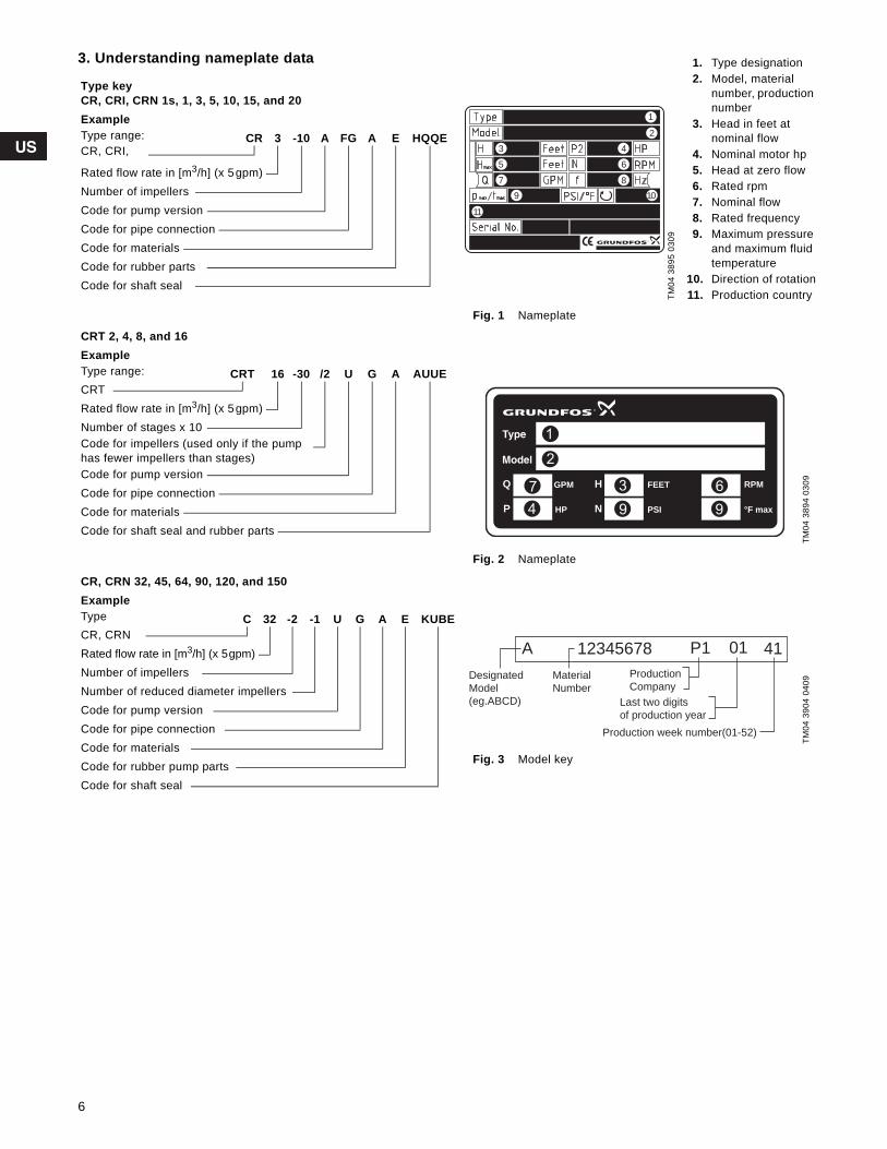
Grundfos.bk Page 6 Wednesday, March 18, 2009 10:38 AM
3. Understanding nameplate data
Fig. 1 Nameplate
Fig. 2 Nameplate
Fig. 3 Model key
Type keyCR, CRI, CRN 1s, 1, 3, 5, 10, 15, and 20ExampleType range: CR 3 -10 A FG A E HQQECR, CRI,
Rated flow rate in [m3/h] (x 5gpm)Number of impellersCode for pump versionCode for pipe connectionCode for materialsCode for rubber partsCode for shaft seal
CRT 2, 4, 8, and 16ExampleType range: CRT 16 -30 /2 U G A AUUECRTRated flow rate in [m3/h] (x 5gpm)Number of stages x 10Code for impellers (used only if the pump has fewer impellers than stages)Code for pump versionCode for pipe connectionCode for materialsCode for shaft seal and rubber parts
CR, CRN 32, 45, 64, 90, 120, and 150ExampleType C 32 -2 -1 U G A E KUBECR, CRNRated flow rate in [m3/h] (x 5gpm)Number of impellersNumber of reduced diameter impellersCode for pump versionCode for pipe connectionCode for materialsCode for rubber pump partsCode for shaft seal
TM04
389
5 03
09
1. Type designation2. Model, material
number, production number
3. Head in feet atnominal flow
4. Nominal motor hp5. Head at zero flow6. Rated rpm7. Nominal flow8. Rated frequency9. Maximum pressure
and maximum fluidtemperature
10. Direction of rotation11. Production country
TM04
389
4 03
09TM
04 3
904
0409
1
2
43
6
879 10
5
11
Q H
P N
GPM FEET
HP PSI °F max
RPM
Designated
Model
(eg.ABCD)
Material
Number
Production
Company
Last two digits
of production year
Production week number(01-52)
A 12345678 P1 01 41
6
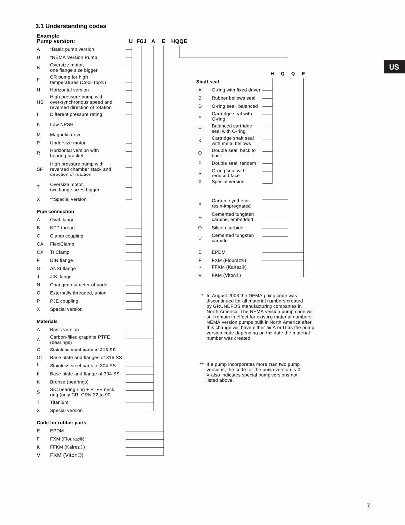
Grundfos.bk Page 7 Wednesday, March 18, 2009 10:38 AM
3.1 Understanding codesExamplePump version: U FGJ A E HQQEA *Basic pump version
U *NEMA Version Pump
B Oversize motor,one flange size bigger
H Q Q EF CR pump for high
temperatures (Cool-Top®) Shaft seal
H Horizontal version A O-ring with fixed driver
HSHigh pressure pump withover-synchronous speed and reversed direction of rotation
B Rubber bellows seal
D O-ring seal, balanced
I Different pressure rating E Cartridge seal withO-ring
K Low NPSHH Balanced cartridge
seal with O-ringM Magnetic drive
K Cartridge shaft seal with metal bellowsP Undersize motor
R Horizontal version withbearing bracket O Double seal, back to
back
SFHigh pressure pump withreversed chamber stack anddirection of rotation
P Double seal, tandem
R O-ring seal withreduced face
T Oversize motor,two flange sizes bigger
X Special version
X **Special versionB Carton, synthetic
resin-impregnatedPipe connection
HCemented tungstencarbine, embedded A Oval flange
B NTP thread Q Silicon carbide
C Clamp coupling U Cemented tungstencarbide
CA FlexiClamp
CX TriClamp E EPDM
F DIN flange F FXM (Flouraz®)
G ANSI flange K FFKM (Kalraz®)
J JIS flange V FKM (Viton®)
N Changed diameter of ports
O Externally threaded, union * In August 2003 the NEMA pump code wasdiscontinued for all material numbers createdby GRUNDFOS manufacturing companies inNorth America. The NEMA version pump code will still remain in effect for existing material numbers. NEMA version pumps built in North America after this change will have either an A or U as the pump version code depending on the date the material number was created.
P PJE coupling
X Special version
Materials
A Basic version
A Carbon-filled graphite PTFE(bearings)
G Stainless steel parts of 316 SS
GI Base plate and flanges of 316 SSI Stainless steel parts of 304 SS ** If a pump incorporates more than two pump
versions, the code for the pump version is X.X also indicates special pump versions notlisted above.
II Base plate and flange of 304 SS
K Bronze (bearings)
S SiC bearing ring + PTFE neckring (only CR, CRN 32 to 90
T Titanium
X Special version
Code for rubber parts
E EPDM
F FXM (Flouraz®)
K FFKM (Kalrez®)
V FKM (Viton®)
7
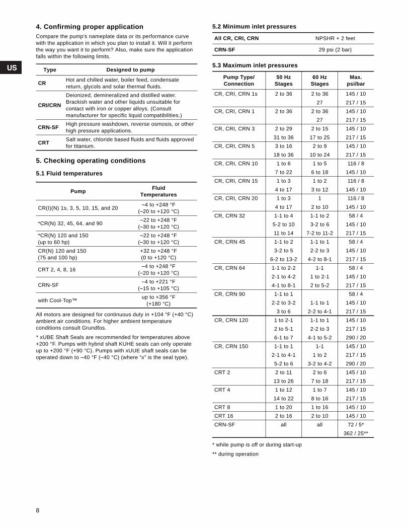
Grundfos.bk Page 8 Wednesday, March 18, 2009 10:38 AM
4. Confirming proper applicationCompare the pump’s nameplate data or its performance curve with the application in which you plan to install it. Will it perform the way you want it to perform? Also, make sure the application falls within the following limits.
5. Checking operating conditions
5.1 Fluid temperaturess
All motors are designed for continuous duty in +104 °F (+40 °C) ambient air conditions. For higher ambient temperatureconditions consult Grundfos.
* xUBE Shaft Seals are recommended for temperatures above +200 °F. Pumps with hybrid shaft KUHE seals can only operate up to +200 °F (+90 °C). Pumps with xUUE shaft seals can be operated down to –40 °F (–40 °C) (where “x” is the seal type).
5.2 Minimum inlet pressures
5.3 Maximum inlet pressures
* while pump is off or during start-up
** during operation
Type Designed to pump
CR Hot and chilled water, boiler feed, condensate return, glycols and solar thermal fluids.
CRI/CRN
Deionized, demineralized and distilled water. Brackish water and other liquids unsuitable for contact with iron or copper alloys. (Consultmanufacturer for specific liquid compatibilities.)
CRN-SF High pressure washdown, reverse osmosis, or other high pressure applications.
CRT Salt water, chloride based fluids and fluids approved for titanium.
Pump FluidTemperatures
CR(I)(N) 1s, 3, 5, 10, 15, and 20 –4 to +248 °F(–20 to +120 °C)
*CR(N) 32, 45, 64, and 90 –22 to +248 °F(–30 to +120 °C)
*CR(N) 120 and 150(up to 60 hp)
–22 to +248 °F(–30 to +120 °C)
CR(N) 120 and 150(75 and 100 hp)
+32 to +248 °F(0 to +120 °C)
CRT 2, 4, 8, 16 –4 to +248 °F(–20 to +120 °C)
CRN-SF –4 to +221 °F(–15 to +105 °C)
with Cool-Top™ up to +356 °F(+180 °C)
All CR, CRI, CRN NPSHR + 2 feet
CRN-SF 29 psi (2 bar)
Pump Type/Connection
50 HzStages
60 HzStages
Max.psi/bar
CR, CRI, CRN 1s 2 to 36 2 to 36 145 / 1027 217 / 15
CR, CRI, CRN 1 2 to 36 2 to 36 145 / 1027 217 / 15
CR, CRI, CRN 3 2 to 29 2 to 15 145 / 1031 to 36 17 to 25 217 / 15
CR, CRI, CRN 5 3 to 16 2 to 9 145 / 1018 to 36 10 to 24 217 / 15
CR, CRI, CRN 10 1 to 6 1 to 5 116 / 87 to 22 6 to 18 145 / 10
CR, CRI, CRN 15 1 to 3 1 to 2 116 / 84 to 17 3 to 12 145 / 10
CR, CRI, CRN 20 1 to 3 1 116 / 84 to 17 2 to 10 145 / 10
CR, CRN 32 1-1 to 4 1-1 to 2 58 / 45-2 to 10 3-2 to 6 145 / 1011 to 14 7-2 to 11-2 217 / 15
CR, CRN 45 1-1 to 2 1-1 to 1 58 / 43-2 to 5 2-2 to 3 145 / 10
6-2 to 13-2 4-2 to 8-1 217 / 15CR, CRN 64 1-1 to 2-2 1-1 58 / 4
2-1 to 4-2 1 to 2-1 145 / 104-1 to 8-1 2 to 5-2 217 / 15
CR, CRN 90 1-1 to 1 58 / 42-2 to 3-2 1-1 to 1 145 / 10
3 to 6 2-2 to 4-1 217 / 15CR, CRN 120 1 to 2-1 1-1 to 1 145 / 10
2 to 5-1 2-2 to 3 217 / 156-1 to 7 4-1 to 5-2 290 / 20
CR, CRN 150 1-1 to 1 1-1 145 / 102-1 to 4-1 1 to 2 217 / 155-2 to 6 3-2 to 4-2 290 / 20
CRT 2 2 to 11 2 to 6 145 / 1013 to 26 7 to 18 217 / 15
CRT 4 1 to 12 1 to 7 145 / 1014 to 22 8 to 16 217 / 15
CRT 8 1 to 20 1 to 16 145 / 10CRT 16 2 to 16 2 to 10 145 / 10CRN-SF all all 72 / 5*
362 / 25**
8
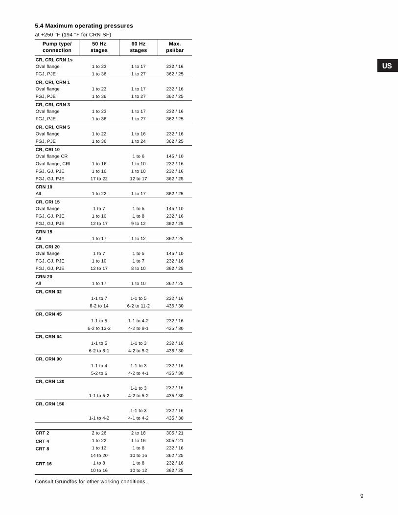
Grundfos.bk Page 9 Wednesday, March 18, 2009 10:38 AM
5.4 Maximum operating pressuresat +250 °F (194 °F for CRN-SF)
Consult Grundfos for other working conditions.
Pump type/connection
50 Hzstages
60 Hzstages
Max.psi/bar
CR, CRI, CRN 1sOval flange 1 to 23 1 to 17 232 / 16FGJ, PJE 1 to 36 1 to 27 362 / 25
CR, CRI, CRN 1Oval flange 1 to 23 1 to 17 232 / 16FGJ, PJE 1 to 36 1 to 27 362 / 25
CR, CRI, CRN 3Oval flange 1 to 23 1 to 17 232 / 16FGJ, PJE 1 to 36 1 to 27 362 / 25
CR, CRI, CRN 5Oval flange 1 to 22 1 to 16 232 / 16FGJ, PJE 1 to 36 1 to 24 362 / 25
CR, CRI 10Oval flange CR 1 to 6 145 / 10Oval flange, CRI 1 to 16 1 to 10 232 / 16FGJ, GJ, PJE 1 to 16 1 to 10 232 / 16FGJ, GJ, PJE 17 to 22 12 to 17 362 / 25
CRN 10All 1 to 22 1 to 17 362 / 25
CR, CRI 15Oval flange 1 to 7 1 to 5 145 / 10FGJ, GJ, PJE 1 to 10 1 to 8 232 / 16FGJ, GJ, PJE 12 to 17 9 to 12 362 / 25
CRN 15All 1 to 17 1 to 12 362 / 25
CR, CRI 20Oval flange 1 to 7 1 to 5 145 / 10FGJ, GJ, PJE 1 to 10 1 to 7 232 / 16FGJ, GJ, PJE 12 to 17 8 to 10 362 / 25
CRN 20All 1 to 17 1 to 10 362 / 25
CR, CRN 321-1 to 7 1-1 to 5 232 / 16
8-2 to 14 6-2 to 11-2 435 / 30
CR, CRN 451-1 to 5 1-1 to 4-2 232 / 16
6-2 to 13-2 4-2 to 8-1 435 / 30
CR, CRN 641-1 to 5 1-1 to 3 232 / 16
6-2 to 8-1 4-2 to 5-2 435 / 30
CR, CRN 901-1 to 4 1-1 to 3 232 / 165-2 to 6 4-2 to 4-1 435 / 30
CR, CRN 1201-1 to 3 232 / 16
1-1 to 5-2 4-2 to 5-2 435 / 30
CR, CRN 1501-1 to 3 232 / 16
1-1 to 4-2 4-1 to 4-2 435 / 30
CRT 2 2 to 26 2 to 18 305 / 21
CRT 4 1 to 22 1 to 16 305 / 21
CRT 8 1 to 12 1 to 8 232 / 1614 to 20 10 to 16 362 / 25
CRT 16 1 to 8 1 to 8 232 / 1610 to 16 10 to 12 362 / 25
9
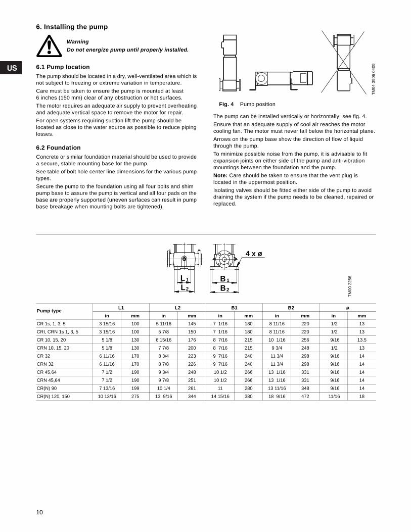
Grundfos.bk Page 10 Wednesday, March 18, 2009 10:38 AM
6. Installing the pump
6.1 Pump locationThe pump should be located in a dry, well-ventilated area which is not subject to freezing or extreme variation in temperature.Care must be taken to ensure the pump is mounted at least6 inches (150 mm) clear of any obstruction or hot surfaces.The motor requires an adequate air supply to prevent overheating and adequate vertical space to remove the motor for repair.For open systems requiring suction lift the pump should belocated as close to the water source as possible to reduce piping losses.
6.2 FoundationConcrete or similar foundation material should be used to provide a secure, stable mounting base for the pump.See table of bolt hole center line dimensions for the various pump types.Secure the pump to the foundation using all four bolts and shim pump base to assure the pump is vertical and all four pads on the base are properly supported (uneven surfaces can result in pump base breakage when mounting bolts are tightened).
Fig. 4 Pump position
The pump can be installed vertically or horizontally; see fig. 4.Ensure that an adequate supply of cool air reaches the motor cooling fan. The motor must never fall below the horizontal plane.Arrows on the pump base show the direction of flow of liquid through the pump.To minimize possible noise from the pump, it is advisable to fit expansion joints on either side of the pump and anti-vibration mountings between the foundation and the pump.Note: Care should be taken to ensure that the vent plug is located in the uppermost position.Isolating valves should be fitted either side of the pump to avoid draining the system if the pump needs to be cleaned, repaired or replaced.
WarningDo not energize pump until properly installed.
TM04
390
6 04
09
TM00
225
6
Pump type L1 L2 B1 B2 øin mm in mm in mm in mm in mm
CR 1s, 1, 3, 5 3 15/16 100 5 11/16 145 7 1/16 180 8 11/16 220 1/2 13
CRI, CRN 1s 1, 3, 5 3 15/16 100 5 7/8 150 7 1/16 180 8 11/16 220 1/2 13
CR 10, 15, 20 5 1/8 130 6 15/16 176 8 7/16 215 10 1/16 256 9/16 13.5
CRN 10, 15, 20 5 1/8 130 7 7/8 200 8 7/16 215 9 3/4 248 1/2 13
CR 32 6 11/16 170 8 3/4 223 9 7/16 240 11 3/4 298 9/16 14
CRN 32 6 11/16 170 8 7/8 226 9 7/16 240 11 3/4 298 9/16 14
CR 45,64 7 1/2 190 9 3/4 248 10 1/2 266 13 1/16 331 9/16 14
CRN 45,64 7 1/2 190 9 7/8 251 10 1/2 266 13 1/16 331 9/16 14
CR(N) 90 7 13/16 199 10 1/4 261 11 280 13 11/16 348 9/16 14
CR(N) 120, 150 10 13/16 275 13 9/16 344 14 15/16 380 18 9/16 472 11/16 18
2
1
2
1
LL
B
4 x ø
B
10
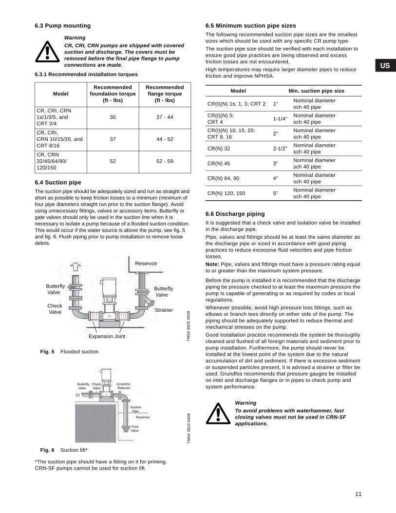
Grundfos.bk Page 11 Wednesday, March 18, 2009 10:38 AM
6.3 Pump mounting
6.3.1 Recommended installation torques
6.4 Suction pipeThe suction pipe should be adequately sized and run as straight and short as possible to keep friction losses to a minimum (minimum of four pipe diameters straight run prior to the suction flange). Avoid using unnecessary fittings, valves or accessory items. Butterfly or gate valves should only be used in the suction line when it isnecessary to isolate a pump because of a flooded suction condition. This would occur if the water source is above the pump; see fig. 5 and fig. 6. Flush piping prior to pump installation to remove loose debris.
Fig. 5 Flooded suction
Fig. 6 Suction lift*
*The suction pipe should have a fitting on it for priming.CRN-SF pumps cannot be used for suction lift.
6.5 Minimum suction pipe sizesThe following recommended suction pipe sizes are the smallest sizes which should be used with any specific CR pump type.The suction pipe size should be verified with each installation to ensure good pipe practices are being observed and excessfriction losses are not encountered.High temperatures may require larger diameter pipes to reduce friction and improve NPHSA.
6.6 Discharge pipingIt is suggested that a check valve and isolation valve be installed in the discharge pipe.Pipe, valves and fittings should be at least the same diameter as the discharge pipe or sized in accordance with good pipingpractices to reduce excessive fluid velocities and pipe frictionlosses.Note: Pipe, valves and fittings must have a pressure rating equal to or greater than the maximum system pressure.
Before the pump is installed it is recommended that the discharge piping be pressure checked to at least the maximum pressure the pump is capable of generating or as required by codes or local regulations.Whenever possible, avoid high pressure loss fittings, such as elbows or branch tees directly on either side of the pump. The piping should be adequately supported to reduce thermal and mechanical stresses on the pump.Good installation practice recommends the system be thoroughly cleaned and flushed of all foreign materials and sediment prior to pump installation. Furthermore, the pump should never beinstalled at the lowest point of the system due to the naturalaccumulation of dirt and sediment. If there is excessive sediment or suspended particles present, it is advised a strainer or filter be used. Grundfos recommends that pressure gauges be installed on inlet and discharge flanges or in pipes to check pump andsystem performance.
WarningCR, CRI, CRN pumps are shipped with covered suction and discharge. The covers must be removed before the final pipe flange to pump connections are made.
ModelRecommended
foundation torque(ft - lbs)
Recommendedflange torque
(ft - lbs)
CR, CRI, CRN1s/1/3/5, andCRT 2/4
30 37 - 44
CR, CRI,CRN 10/15/20, andCRT 8/16
37 44 - 52
CR, CRN32/45/64/90/120/150
52 52 - 59
TM04
392
5 04
09TM
04 3
910
0409
Reservoir
Butterfly
Valve
Butterfly
Valve
StrainerCheck
Valve
Expansion Joint
Butterfly
Valve
Check
Valve
Eccentric
Reducer
Suction
Pipe
Reservior
Foot
Valve
Model Min. suction pipe size
CR(I)(N) 1s, 1, 3; CRT 2 1" Nominal diametersch 40 pipe
CR(I)(N) 5;CRT 4 1-1/4" Nominal diameter
sch 40 pipeCR(I)(N) 10, 15, 20;CRT 8, 16 2" Nominal diameter
sch 40 pipe
CR(N) 32 2-1/2" Nominal diametersch 40 pipe
CR(N) 45 3" Nominal diametersch 40 pipe
CR(N) 64, 90 4" Nominal diametersch 40 pipe
CR(N) 120, 150 5" Nominal diametersch 40 pipe
WarningTo avoid problems with waterhammer, fastclosing valves must not be used in CRN-SFapplications.
11
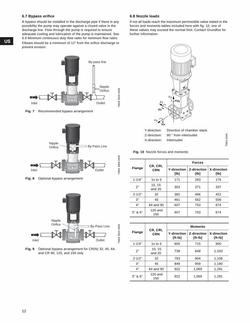
Grundfos.bk Page 12 Wednesday, March 18, 2009 10:38 AM
6.7 Bypass orificeA bypass should be installed in the discharge pipe if there is any possibility the pump may operate against a closed valve in the discharge line. Flow through the pump is required to ensureadequate cooling and lubrication of the pump is maintained. See 6.9 Minimum continuous duty flow rates for minimum flow rates.Elbows should be a minimum of 12” from the orifice discharge to prevent erosion.
Fig. 7 Recommended bypass arrangement
Fig. 8 Optional bypass arrangement
Fig. 9 Optional bypass arrangement for CR(N) 32, 45, 64, and CR 90, 120, and 150 only
6.8 Nozzle loadsIf not all loads reach the maximum permissible value stated in the forces and moments tables included here with fig. 10, one of these values may exceed the normal limit. Contact Grundfos for further information.
Fig. 10 Nozzle forces and moments
TM04
392
6 04
09TM
04 3
909
0409
TM04
392
4 04
09
By-pass line
Nipple
Orifice
Inlet Outlet
Inlet Outlet
By-Pass LineNipple
Orifice
OutletInlet
Nipple
OrificeBy-Pass Line
TM04
034
6
Flange CR, CRI, CRN
Forces
Y-direction[lb]
Z-direction[lb]
X-direction[lb]
1-1/4" 1s to 5 171 263 175
2" 10, 15and 20 303 371 337
2-1/2" 32 382 466 4223" 45 461 562 5064" 64 and 90 607 753 674
5" & 6" 120 and 150 607 753 674
Flange CR, CRI, CRN
Moments
Y-direction[ft-lb]
Z-direction[ft-lb]
X-direction[ft-lb]
1-1/4" 1s to 5 605 715 900
2" 10, 15and 20 738 848 1,033
2-1/2" 32 793 904 1,1063" 45 848 959 1,1804" 64 and 90 922 1,069 1,291
5" & 6" 120 and 150 922 1,069 1,291
Y-direction: Direction of chamber stackZ-direction: 90 ° from inlet/outletX-direction: Inlet/outlet
12

Grundfos.bk Page 13 Wednesday, March 18, 2009 10:38 AM
6.9 Minimum continuous duty flow rates
* Grundfos Cool-Top® is only available in the following pump types.
6.10 Check valvesA check valve may be required on the discharge side of the pump to prevent the pump’s inlet pressure from being exceeded.For example, if a pump with no check valve is stopped because there is no demand on the system (all valves are closed), the high system pressure on the discharge side of the pump will “find” its way back to the inlet of the pump.If the system pressure is greater than the pump’s maximum inlet pressure rating, the limits of the pump will be exceeded and a check valve needs to be fitted on the discharge side of the pump to prevent this condition. This is especially critical for CRN-SF applications because of the very high discharge pressuresinvolved. As a result, most CRN-SF installations require a check valve on the discharge piping.
6.11 Temperature riseIt may sometimes be necessary to stop the flow through a pump during operation.At shut-off, the power to the pump is transferred to the pumped liquid as head, causing a temperature rise in the liquid.The result is risk of excess heating of and consequent damage to the pump. The risk depends on the temperature of the pumped liquid and for how long the pump is operating without flow; see the following temperature rise chart.
6.12 Conditions/ReservationsThe listed times are subject to the following conditions/reservations:• No exchange of heat with the surrounding.• The pumped liquid is water with a specific heat of 1.0 Btu/lb. °F
(4.18 kJ/kg °C).• Pump parts (chambers, impellers and shaft) have the same
thermal capacity as water.• The water in the base and the pump head is not included.These reservations should give sufficient safety margin against excessive temperature rise.The maximum temperature must not exceed the pump maximum rating.
Pump Type min °F to 176 °F(min °C to 80 °C)
at 210°F(at 99°C)
at 248°F(at 120°C)
at 356°F(at 180°C)
CR, CRI, CRN 1s 0.5 0.7 1.2 1.2*CR, CRI, CRN 1 0.9 1.3 2.3 2.3*CR, CRI, CRN 3 1.6 2.4 4.0 4.0*CR, CRI, CRN 5 3.0 4.5 7.5 7.5*CR, CRI, CRN 10 5.5 8.3 14 14*CR, CRI, CRN 15 9.5 14 24 24*CR, CRI, CRN 20 11 17 28 28*CR, CRN 32 14 21 35 35*CR, CRN 45 22 33 55 55*CR, CRN 64 34 51 85 85*CR, CRN 90 44 66 110 110*CR, CRN 120 60 90 N/A N/ACR, CRN 150 75 115 N/A N/ACRT 2 1.3 2.0 3.3 N/ACRT 4 3.0 4.5 7.5 N/ACRT 8 4.0 6.0 10 N/ACRT 16 8.0 0.7 20 N/A
Pump Type CR 1s CR 1 CR 3 CR 5 CR 10 CR 15 CR 20 CR 32 CR 45 CR 64 CR 90
Standard (CR) • • • •I Version (CRI) • • • • • • •N Version (CRN) • • • • • • • • • • •
Pump typeTime for temperature rise
of 18 °F (10 °C)
Seconds Minutes
CR 1s, 1, 3 210 3.5
CR 5 240 4.0
CR 10 210 3.5
CR 15 150 2.5
CR 20 120 2.0
CR 32, 45, 64, 90, 120, 150 60 1.0
13
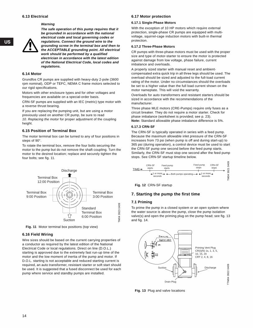
Grundfos.bk Page 14 Wednesday, March 18, 2009 10:38 AM
6.13 Electrical
6.14 MotorGrundfos CR pumps are supplied with heavy-duty 2-pole (3600 rpm nominal), ODP or TEFC, NEMA C frame motors selected to our rigid specifications.Motors with other enclosure types and for other voltages andfrequencies are available on a special-order basis.CRN-SF pumps are supplied with an IEC (metric) type motor with a reverse thrust bearing.If you are replacing the pumping unit, but are using a motorpreviously used on another CR pump, be sure to read 10. Replacing the motor for proper adjustment of the coupling height.
6.15 Position of Terminal BoxThe motor terminal box can be turned to any of four positions in steps of 90°.To rotate the terminal box, remove the four bolts securing the motor to the pump but do not remove the shaft coupling. Turn the motor to the desired location; replace and securely tighten the four bolts; see fig. 11.
Fig. 11 Motor terminal box positions (top view)
6.16 Field WiringWire sizes should be based on the current carrying properties of a conductor as required by the latest edition of the NationalElectrical Code or local regulations. Direct on line (D.O.L.)starting is approved due to the extremely fast run-up time of the motor and the low moment of inertia of the pump and motor. If D.O.L. starting is not acceptable and reduced starting current is required, an auto transformer, resistant starter or soft start should be used. It is suggested that a fused disconnect be used for each pump where service and standby pumps are installed.
6.17 Motor protection6.17.1 Single-Phase Motors With the exception of 10 HP motors which require externalprotection, single-phase CR pumps are equipped with multi-voltage, squirrel-cage induction motors with built-in thermalprotection.
6.17.2 Three-Phase MotorsCR pumps with three-phase motors must be used with the proper size and type of motor-starter to ensure the motor is protected against damage from low voltage, phase failure, currentimbalance and overloads. A properly sized starter with manual reset and ambient-compensated extra quick trip in all three legs should be used. The overload should be sized and adjusted to the full-load current rating of the motor. Under no circumstances should the overloads be set to a higher value than the full load current shown on the motor nameplate. This will void the warranty.Overloads for auto transformers and resistant starters should be sized in accordance with the recommendations of themanufacturer. Three phase MLE motors (CRE-Pumps) require only fuses as a circuit breaker. They do not require a motor starter. Check for phase imbalance (worksheet is provided; see p. 23).Note: Standard allowable phase imbalance difference is 5%.
6.17.3 CRN-SFThe CRN-SF is typically operated in series with a feed pump. Because the maximum allowable inlet pressure of the CRN-SF increases from 73 psi (when pump is off and during start-up) to 365 psi (during operation), a control device must be used to start the CRN-SF pump one second before the feed pump starts.Similarly, the CRN-SF must stop one second after the feed pump stops. See CRN-SF startup timeline below.
Fig. 12 CRN-SF startup
7. Starting the pump the first time
7.1 PrimingTo prime the pump in a closed system or an open system where the water source is above the pump, close the pump isolation valve(s) and open the priming plug on the pump head; see fig. 13 and fig. 14.
Fig. 13 Plug and valve locations
WarningThe safe operation of this pump requires that it be grounded in accordance with the national electrical code and local governing codes orregulations. Connect the ground wire to the grounding screw in the terminal box and then to the ACCEPTABLE grounding point. All electrical work should be performed by a qualifiedelectrician in accordance with the latest edition of the National Electrical Code, local codes and regulations.
TM04
392
3 04
09
Discharge
Terminal Box
12:00 Position
Standard
Terminal Box
6:00 Position
Terminal Box
9:00 Position
Terminal Box
3:00 Position
Suction
TM04
392
1 04
09TT
M04
392
2 04
09
TIME
CRN-SF
starts
CRN-SF
stopsFeed pump
starts
Feed pump
stops
1 or more
seconds
1 or more
secondsBoth pumps operating
Drain Plug
DischargeSuction
Priming Vent Plug
CR(I)(N) 1s, 1, 3, 5,
10, 15, 20
CRT 2, 4, 8, 16
14
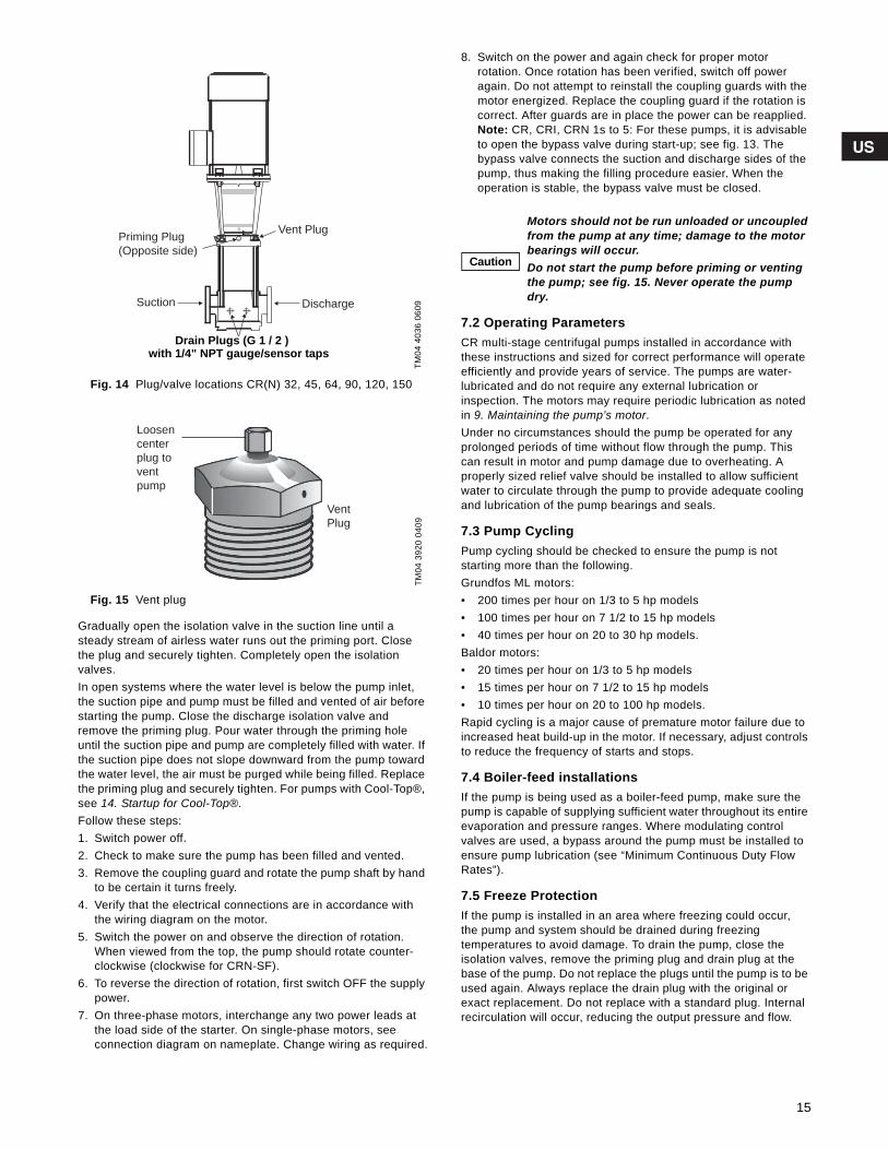
Grundfos.bk Page 15 Wednesday, March 18, 2009 10:38 AM
Fig. 14 Plug/valve locations CR(N) 32, 45, 64, 90, 120, 150
Fig. 15 Vent plug
Gradually open the isolation valve in the suction line until a steady stream of airless water runs out the priming port. Close the plug and securely tighten. Completely open the isolationvalves.In open systems where the water level is below the pump inlet, the suction pipe and pump must be filled and vented of air before starting the pump. Close the discharge isolation valve and remove the priming plug. Pour water through the priming hole until the suction pipe and pump are completely filled with water. If the suction pipe does not slope downward from the pump toward the water level, the air must be purged while being filled. Replace the priming plug and securely tighten. For pumps with Cool-Top®, see 14. Startup for Cool-Top®.Follow these steps:1. Switch power off.2. Check to make sure the pump has been filled and vented.3. Remove the coupling guard and rotate the pump shaft by hand
to be certain it turns freely.4. Verify that the electrical connections are in accordance with
the wiring diagram on the motor.5. Switch the power on and observe the direction of rotation.
When viewed from the top, the pump should rotate counter-clockwise (clockwise for CRN-SF).
6. To reverse the direction of rotation, first switch OFF the supply power.
7. On three-phase motors, interchange any two power leads at the load side of the starter. On single-phase motors, see connection diagram on nameplate. Change wiring as required.
8. Switch on the power and again check for proper motorrotation. Once rotation has been verified, switch off power again. Do not attempt to reinstall the coupling guards with themotor energized. Replace the coupling guard if the rotation is correct. After guards are in place the power can be reapplied. Note: CR, CRI, CRN 1s to 5: For these pumps, it is advisable to open the bypass valve during start-up; see fig. 13. The bypass valve connects the suction and discharge sides of the pump, thus making the filling procedure easier. When the operation is stable, the bypass valve must be closed.
.
7.2 Operating ParametersCR multi-stage centrifugal pumps installed in accordance with these instructions and sized for correct performance will operate efficiently and provide years of service. The pumps are water-lubricated and do not require any external lubrication orinspection. The motors may require periodic lubrication as noted in 9. Maintaining the pump’s motor.Under no circumstances should the pump be operated for any prolonged periods of time without flow through the pump. This can result in motor and pump damage due to overheating. Aproperly sized relief valve should be installed to allow sufficient water to circulate through the pump to provide adequate cooling and lubrication of the pump bearings and seals.
7.3 Pump CyclingPump cycling should be checked to ensure the pump is notstarting more than the following.Grundfos ML motors:• 200 times per hour on 1/3 to 5 hp models • 100 times per hour on 7 1/2 to 15 hp models • 40 times per hour on 20 to 30 hp models.Baldor motors:• 20 times per hour on 1/3 to 5 hp models • 15 times per hour on 7 1/2 to 15 hp models • 10 times per hour on 20 to 100 hp models.Rapid cycling is a major cause of premature motor failure due to increased heat build-up in the motor. If necessary, adjust controls to reduce the frequency of starts and stops.
7.4 Boiler-feed installationsIf the pump is being used as a boiler-feed pump, make sure the pump is capable of supplying sufficient water throughout its entire evaporation and pressure ranges. Where modulating controlvalves are used, a bypass around the pump must be installed to ensure pump lubrication (see “Minimum Continuous Duty Flow Rates”).
7.5 Freeze ProtectionIf the pump is installed in an area where freezing could occur,the pump and system should be drained during freezingtemperatures to avoid damage. To drain the pump, close theisolation valves, remove the priming plug and drain plug at the base of the pump. Do not replace the plugs until the pump is to be used again. Always replace the drain plug with the original or exact replacement. Do not replace with a standard plug. Internal recirculation will occur, reducing the output pressure and flow.
TM04
403
6 06
09TM
04 3
920
0409
Priming Plug
(Opposite side)
Drain Plugs (G 1 / 2 A)
with 1 / 4” NPI gauge/sensor taps
Discharge
Vent Plug
Suction
Drain Plugs (G 1 / 2 )with 1/4" NPT gauge/sensor taps
Loosen
center
plug to
vent
pump
Vent
Plug
Caution
Motors should not be run unloaded or uncoupled from the pump at any time; damage to the motor bearings will occur.Do not start the pump before priming or venting the pump; see fig. 15. Never operate the pump dry.
15
Grundfos.bk Page 16 Wednesday, March 18, 2009 10:38 AM
8. Preventative pump maintenanceAt regular intervals depending on the conditions and time ofoperation, the following checks should be made:1. Pump meets required performance and is operating smoothly
and quietly.2. There are no leaks, particularly at the shaft seal.3. The motor is not overheating.4. Remove and clean all strainers or filters in the system.5. Verify the tripping of the motor overload protection.6. Check the operation of all controls. Check unit control cycling
twice and adjust, if necessary.7. If the pump is not operated for unusually long periods, the unit
should be maintained in accordance with these instructions. In addition, if the pump is not drained, the pump shaft should be manually rotated or run for short periods of time at monthly intervals.
8. To extend the pump life in severe duty applications, consider performing one of the following actions:– Drain the pump after each use.– Flush the pump, through system, with water or other fluid
that is compatible with the pump materials and process liquid.
– Disassemble the pump liquid components and thoroughly rinse or wash them with water or other fluid that iscompatible with the pump materials and process liquid.
If the pump fails to operate or there is a loss of performance, refer to Section 15. Diagnosing specific problems.
9. Maintaining the pump’s motor
9.1 Motor InspectionInspect the motor at regular intervals, approximately every 500 hours of operation or every three months, whichever occurs first. Keep the motor clean and the ventilation openings clear.
The following steps should be performed at each inspection:1. Check that the motor is clean. Check that the interior and
exterior of the motor is free of dirt, oil, grease, water, etc. Oily vapor, paper, pulp, textile lint, etc. can accumulate and block motor ventilation. If the motor is not properly ventilated,overheating can occur and cause early motor failure.
2. Use an Ohmmeter (“Megger”) periodically to ensure that the integrity of the winding insulation has been maintained. Record the Ohmmeter readings. Immediately investigate any significant drop in insulation resistance.
3. Check all electrical connectors to be sure that they are tight.
9.2 Motor LubricationElectric motors are pre-lubricated at the factory and do not require additional lubrication at start-up. Motors without external grease fittings have sealed bearings that cannot be re-lubricated. Motors with grease fittings should only be lubricated withapproved types of grease. Do not over-grease the bearings. Over-greasing will cause increased bearing heat and can result in bearing/motor failure. Do not mix petroleum grease and silicon grease in motor bearings.Bearing grease will lose its lubricating ability over time, notsuddenly. The lubricating ability of a grease (over time) depends primarily on the type of grease, the size of the bearings, the speed at which the bearings operate and the severity of theoperating conditions.Good results can be obtained if the following recommendations are used in your maintenance program. It should also be noted that pumps with more stages, pumps running to the left of the performance curve, and certain pump ranges may have higher thrust loads. Pumps with high thrust loads should be greased according to the next service interval level.
9.3 Recommended lubricant
Note: If pump is fitted with a bearing flange that requires grease, see the stickers on either the bearing flange or coupling guards for proper grease type and greasing schedule.
WarningDo not touch electrical connections before you first ensure that power has been disconnected. Electrical shock can cause serious or fatal injury. Only qualified personnel should attempt installation, operation, and maintenance of this equipment.
Severity of service Ambient temp. (max.) Environment Approved types of grease
Standard +104 °F (+40 °C) Clean, little corrosion Grundfos ML motors are greased for life or will have the grease type on the nameplate. Baldor motors are greased with Polyrex EM (Exxon Mobile).
Severe +122 °F (+50 °C) Moderate dirt, corrosion
Extreme >122 °F (+50°C)or Class H insulation
Severe dirt, abrasive dust,corrosion
16
Grundfos.bk Page 17 Wednesday, March 18, 2009 10:38 AM
9.4 Motor lubrication schedule(for motors with grease nipples)
New motors that have been stored for a year or more should be regreased according to the following:
9.5 Lubrication Procedure
1. Clean all grease fittings. If the motor does not have greasefittings, the bearing is sealed and cannot be greasedexternally.
2. If the motor is equipped with a grease outlet plug, remove it. This will allow the old grease to be displaced by the new grease. If the motor is stopped, add the recommended amount of grease. If the motor is to be greased while running, a slightly greater quantity of grease will have to be added.Note: If new grease does not appear at the shaft hole or grease outlet plug, the outlet passage may be blocked. At the next service interval the bearings must be repacked.
3. Add grease SLOWLY taking approximately one minute until new grease appears at the shaft hole in the endplate or grease outlet plug. Never add more than 1-1/2 times the amount of grease shown in the lubrication schedule.
4. For motors equipped with a grease outlet plug, let the motor run for 20 minutes before replacing the plug.
10. Replacing the motorIf the motor is damaged due to bearing failure, burning or electrical failure, the following instructions detail how to remove the motor for replacement.
10.1 DisassemblyFor disassembly, proceed as follows:1. Turn off and lock out power supply. The power supply wiring
can now be safely disconnected from the motor wires. Remove the coupling guards. Note: CR 1s, 1, 3, 5, 10, 15, and 20: do not loosen the three shaft seal securing allen screws.
2. Using the proper metric Allen wrench, loosen the four cap screws in the coupling. Completely remove coupling halves. On CR1s-CR20, the shaft pin can be left in the pump shaft. CR(N)32, 45, 64, 90, 120, and 150 do not have a shaft pin.
3. With the correct size wrench, loosen and remove the four bolts which hold the motor to the pump end.
4. Lift the motor straight up until the shaft has cleared the motor stool.
10.2 AssemblyFor assembly, proceed as follows:1. Remove key from motor shaft, if present, and discard.2. Thoroughly clean the surfaces of the motor and pump end
mounting flange. The motor and shaft must be clean of all oil/grease and other contaminants where the coupling attaches. Set the motor on the pump end.
3. Place the terminal box in the desired position by rotating the motor.
4. Insert the mounting bolts, then diagonally and evenly tighten:– for 3/8” bolts (1/2 to 2 hp), torque to 17 ft-lb– for 1/2” bolts (3 to 40 hp) torque to 30 ft-lb– for 5/8” bolts (50 - 100 hp) torque to 59 ft-lb– follow instructions for particular pump model in sections
10.2.1 Torque specifications for CR 1s, 1, 3, and 5 through 10.2.4 CR(N) 32, 45, 64, 90, 120, and 150.
NEMA (IEC)Frame Size
Standard Service Interval
SevereService Interval
ExtremeService Interval
Weight of grease to add
[oz (grams)]
Volume of grease to add
[in3 (teaspoons)]
Up through 210(132) 5500 hrs 2750 hrs 550 hrs 0.30 (8.4) 0.6 (2)
Over 210 through 280 (180) 3600 hrs 1800 hrs 360 hrs 0.61 (17.4)* 1.2 (3.9)
Over 280 up through 360 (225) 2200 hrs 1100 hrs 220 hrs 0.81 (23.1)* 1.5 (5.2)
Over 360(225) 2200 hrs 1100 hrs 220 hrs 2.12 (60.0)* 4.1 (13.4)
WarningThe grease outlet plug MUST be removed before adding new grease.
Caution
To avoid damage to motor bearings, grease must be kept free of dirt. For an extremely dirtyenvironment, contact Grundfos, the motormanufacturer, or an authorized service center for additional information.Mixing dissimilar grease is not recommended.
Caution
It must be emphasized that motors used on CR pumps are specifically selected to our rigidspecifications. Replacement motors must be of the same frame size, should be equipped with the same or better bearings and have the same service factor. Failure to follow these recommendations may result in premature motor failure.
17

Grundfos.bk Page 18 Wednesday, March 18, 2009 10:38 AM
10.2.1 Torque specifications for CR 1s, 1, 3, and 5Insert shaft pin into shaft hole. Reinstall the coupling halves onto shaft and shaft pin. Reinstall the coupling screws and leave loose. Check that the gaps on either side of the coupling are even, and that the motor shaft keyway is centered in the coupling half, as shown in fig. 16.Tighten the screws to the correct torque; see torque specifications table below.
10.2.2 CR 10, 15 and 20Insert shaft pin into shaft hole. Insert plastic shaft seal spacer beneath shaft seal collar. Reinstall the coupling halves onto shaft and shaft pin. Reinstall the coupling screws and leave loose. Check that the gaps on either side of the coupling are even and that the motor shaft key way is centered in the coupling half, as shown in fig. 16. Tighten the screws to the correct torque. Remove plastic shaft seal spacer and hang it on inside ofcoupling guard.
Fig. 16 Coupling adjustment all CR(I)(N)(X)(T)
10.2.3 CRT 2, 4, 8 and 16Reinstall coupling halves. Make sure the shaft pin is located in the pump shaft. Put the cap screws loosely back into the coupling halves.Using a large screwdriver, raise the pump shaft by placing the tip of the screwdriver under the coupling and carefully elevatingcoupling to its highest point; see fig. 17.
Fig. 17 Coupling adjustment CRT 2, 4, 8, and 16
Note: The shaft can only be raised approximately 0.20 in (5mm). Now lower the shaft halfway back down the distance you just raised it and tighten the coupling screws (finger tight) while keeping the coupling separation equal on both sides. When the screws are tight enough to keep the couplings in place, then torque the screws evenly in a criss-cross pattern.
Fig. 18 Coupling adjustment clearance CRT 2, 4, 8, and 16
10.2.4 CR(N) 32, 45, 64, 90, 120, and 1501. Make sure shaft is all the way down. TIghten the set screws on
the mechanical seal.2. Place the plastic adjustment fork under the cartridge seal
collar; see fig. 19.
Fig. 19 Coupling adjustmentCR(N) 32, 45, 64, 90, 120, and 150
3. Fit the coupling on the shaft so that the top of the pump shaft is flush with the bottom of the clearance chamber in thecoupling; see fig. 20.Note: To avoid damaging the coupling halves, ensure that no portion of the keyway on the motor shaft lies within the gap between the two coupling halves.
Fig. 20 Coupling adjustment clearanceCR(N) 32, 45, 64, 90, 120, and 150
Torque specificationsCR(I)(N) 1s, 1, 3, 5, 10, 15, and 20
CRT 2, 4, 8, and 16
Coupling bolt size Min. torque
M6 10 ft-lbM8 23 ft-lb
M10 46 ft-lb
TM04
391
9 04
09TM
02 1
051
0501
CORRECT
CORRECT NOT CORRECT
TOP
View
Gap between coupling
Keyway Keyway
M6 - 13 NmM8 - 31 NmM10 - 62 Nm
0.5x
x
TM02
105
1 05
01TM
04 3
913
0409
TM04
391
4 04
09
• Note the clearance below the coupling
• Raise the coupling higher, as far as it will go
• Lower it halfway back down(1/2 the distance you just raised it)
• Tighten screws (see torque specifications below)
18

Grundfos.bk Page 19 Wednesday, March 18, 2009 10:38 AM
4. Lubricate the coupling screws with an anti-seize andlubricating compound. Tighten the coupling screws (finger tight) while keeping the coupling separation equal on both sides and the motor shaft keyway centered in the coupling half as shown in fig. 16.
5. When the screws are tight enough to keep the couplings in place, then torque the screws evenly in a crisscross pattern.
6. Torque coupling screws to 62 ft.-lbs (75 and 100 hp motors to 74 ft-lbs). Remove the adjustment fork from under the cartridge seal collar and replace it to the storage location; see fig. 21.
Fig. 21 Adjustment fork storageCR(N) 32, 45, 64, 90, 120, and 150
7. Check to see that the gaps between the coupling halves are equal. Loosen and readjust, if necessary.
8. Be certain the pump shaft can be rotated by hand. If the shaft cannot be rotated or it binds, disassemble and check formisalignment.
9. Prime the pump.10.Follow the wiring diagram on the motor label for the correct
motor wiring combination which matches your supply voltage. Once this has been confirmed, reconnect the power supply wiring to the motor.
11.Check the direction of rotation, by bump-starting the motor. Rotation must be left to right (counter-clockwise) when looking directly at the coupling.
12.Shut off the power, then re-install the coupling guards. After the coupling guards have been installed the power can be turned back on.
11. Parts ListFor each CR pump model Grundfos offers an extensive Parts List and diagram of part used in that pump and is recommended to have on hand for future maintenance. In addition, the listings also provide information about prepackaged Service Kits for those pump components most likely to exhibit wear over time, as well as the complete Impeller Stack needed to replace the “guts” of each model. These Parts Lists are available separately from the Grundfos literature warehouse or as a set with extensive service instructions in the Grundfos CR Service Manuals (for a small charge).
Fig. 22 Prepackaged impeller stack kits
Fig. 23 Prepackaged flange kits
12. Spare PartsGrundfos offers an extensive list of spare parts. For a current list of these parts, refer to: “All Product Spare Parts/Service Kits” Price List, Form #L-SK-SL-002.
TM04
391
5 04
09
TM04
391
7 04
09TM
04 3
916
0409
19
Grundfos.bk Page 20 Wednesday, March 18, 2009 10:38 AM
13. Preliminary electrical tests
13.1 Supply voltage13.1.1 How to measure the supply voltageUse a voltmeter, (set to the proper scale) measure the voltage at the pump terminal box or starter.On single-phase units, measure between power leads L1 and L2 (or L1 and N for 115 volt units).On three-phase units, measure between:
– Power leads L1 and L2– Power leads L2 and L3– Power leads L3 and L1
Fig. 24 Measuring supply voltage
13.1.2 What the supply voltage measurement meansWhen the motor is under load, the voltage should be within ±10% of the nameplate voltage. Larger voltage variation may cause winding damage.Large variations in the voltage indicate a poor electrical supply and the pump should not be operated until these variations have been corrected.If the voltage constantly remains high or low, the motor should be changed to the correct supply voltage.
13.2 Current measurement13.2.1 How to measure the currentUse an ammeter (set on the proper scale) to measure the current on each power lead at the terminal box or starter. See the motor nameplate for amp draw information.Current should be measured when the pump is operating atconstant discharge pressure.
Fig. 25 Measuring current
13.2.2 What the current measurement meansIf the amp draw exceeds the listed service factor amps (SFA) or if the current imbalance is greater than 5% between each leg on three-phase units, check the following:
– Burned contacts on motor starter.– Loose terminals in starter or terminal box or possible wire
defect.– Too high or too low supply voltage.– Motor windings are shorted or grounded. Check winding and
insulation resistances.– Pump is damaged causing a motor overload.
13.3 Insulation resistance13.3.1 How to measure the insulation resistanceTurn off power and disconnect the supply power leads in the pump terminal box. Using an ohm or mega ohm meter, set the scale selector to Rx 100K and zero adjust the meter.Measure and record the resistance between each of the terminals and ground.
Fig. 26 Measuring insulation resistance
13.3.2 What the insulation resistance meansMotors of all hp, voltage, phase and cycle duties have the same value of insulation resistance. Resistance values for new motors must exceed 1,000,000 ohms. If they do not, motor should be repaired or replaced.
WarningWhen working with electrical circuits, use caution to avoid electrical shock. It is recommended that rubber gloves and boots be worn, and metalterminal boxes and motors are grounded before any work is done. For your protection, alwaysdisconnect the pump from its power source before handling.
TM04
391
1 04
09
TM04
390
8 04
09TM
04 3
907
0409
20
Grundfos.bk Page 21 Wednesday, March 18, 2009 10:38 AM
14. Startup for Cool-Top®
Caution Do not start the pump until it has been filled with liquid and vented.
WarningPay attention to the direction of the vent hole and take care to ensure that the escaping liquid does not cause injury to persons or damage to the motor or other components. In hot-liquid installations, special attention should be paid to the risk of injury caused by scalding hot liquid. It is recommended to connect a drain pipe to the 1/2" air vent in order to lead the hot water/steam to a safe place.
Step Action
1
TM02
415
1 50
01
Note: The air-cooled top should only be started up with cold liquid. Close the isolation valve on the discharge side and open the isolation valve on the suction side of the pump.
2
TM02
415
3 15
03Remove the priming plug from the air-cooled chamber (2) and slowly fill the chamber with liquid.
When the chamber is completely filled with liquid, replace the priming plug and tighten securely.
3
TM02
590
7 40
02
Open the isolation valve on the discharge side of the pump. Valve may have to be partially closed when pump is started if no back pressure is present (i.e. boiler not up to pressure).
4
TM01
414
06 3
702
TM01
140
5 44
97
Start the pump and check the direction of rotation.
See the correct rotation of the pump on the motor fan cover.
If the direction of rotation is wrong, interchange any two of the incoming supply wires.
After 3 to 5 minutes, the air vent has been filled with liquid.
Note: During startup of a cold pump with hot liquid, it is normal that a few drops of liquid are leaking from the sleeve.
21

Grundfos.bk Page 22 Wednesday, March 18, 2009 10:38 AM
15. Diagnosing specific problems
Problem Possible cause Remedy
The pump does not run. 1. No power at motor. Check voltage at motor terminal box. If no voltage at motor, check feeder panel for tripped circuits and reset circuit.
2. Fuses are blown or circuit breakers are tripped.
Turn off power and remove fuses. Check for continuity with ohmmeter. Replace blown fuses or reset circuit breaker. If new fuses blow or circuit breaker trips, the electrical installation, motor and wires must be checked.
3. Motor starter overloads are burned or have tripped out.
Check for voltage on line and load side of starter. Replace burned heaters or reset. Inspect starter for other damage. If heater trips again, check the supply voltage and starter holding coil.
4. Starter does not energize.Energize control circuit and check for voltage at the holding coil. If no voltage, check control circuit fuses. If voltage, check holding coil for shorts. Replace bad coil.
5. Defective controls.Check all safety and pressure switches for operation. Inspect contacts in control devices. Replace worn or defective parts or controls.
6. Motor is defective.
Turn off power and disconnect wiring. Measure the lead to lead resistances with ohmmeter (RX-1). Measure lead to ground values with ohmmeter (RX-100K). Record measured values. If an open or grounded winding is found, remove motor and repair or replace.
7. Defective capacitor(single-phase motors).
Turn off power and discharge capacitor. Check with ohmme-ter (RX-100K). When the meter is connected to the capaci-tor, the needle should jump towards 0 ohms and slowly drift back to infinity (h). Replace if defective.
8. Pump is bound.
Turn off power and manually rotate pump shaft. If shaft does not rotate easily, check coupling setting and adjust as necessary. If shaft rotation is still tight, remove pump and inspect. Disassemble and repair.
The pump runs but at reduced capacity or does not deliver water. 1. Wrong rotation. Check wiring for proper connections. Correct wiring.
2. Pump is not primed or is airbound.Turn pump off, close isolation valve(s), remove priming plug. Check fluid level. Refill the pump, replace plug and start the pump. Long suction lines must be filled before starting the pump.
3. Strainers, check or foot valves are clogged.
Remove strainer, screen or valve and inspect. Clean and replace. Reprime pump.
4. Suction lift too large.
Install compound pressure gauge at the suction side of the pump. Start pump and compare reading to performance data. Reduce suction lift by lowering pump, increase suction line size or removing high friction loss devices.
5. Suction and/or discharge piping leaks.
Pump spins backwards when turned off. Air in suction pipe. Suction pipe, valves and fittings must be airtight. Repair any leaks and retighten all loose fittings.
6. Pump worn.
Install pressure gauge, start pump, gradually close the discharge valve and read pressure at shutoff. Convert measured pressure (in psi) to head (in feet): (Measured psi x 2.31 ft/psi = ___ ft). Refer to the specific pump curve for shutoff head for that pump model. If head is close to curve, pump is probably OK. If not, remove pump and inspect.
7. Pump impeller or guide vane is clogged.
Disassemble and inspect pump passageways. Remove any foreign materials found.
8. Incorrect drain plug is installed. If the proper drain plug is replaced with a standard plug, water will recirculate internally. Replace with proper plug.
9. Improper coupling setting. Check/reset the coupling; see page 18.
22
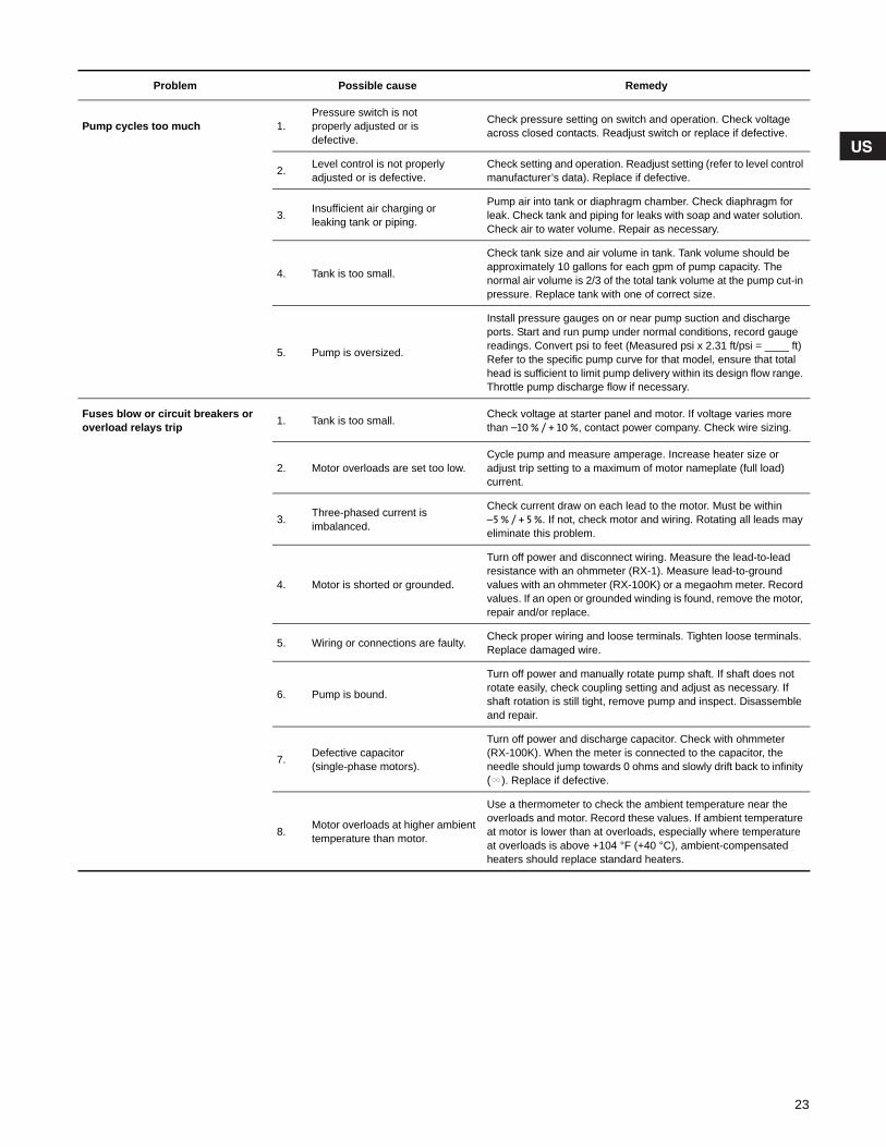
Grundfos.bk Page 23 Wednesday, March 18, 2009 10:38 AM
Problem Possible cause Remedy
Pump cycles too much 1.Pressure switch is notproperly adjusted or isdefective.
Check pressure setting on switch and operation. Check voltage across closed contacts. Readjust switch or replace if defective.
2. Level control is not properly adjusted or is defective.
Check setting and operation. Readjust setting (refer to level control manufacturer’s data). Replace if defective.
3. Insufficient air charging orleaking tank or piping.
Pump air into tank or diaphragm chamber. Check diaphragm for leak. Check tank and piping for leaks with soap and water solution. Check air to water volume. Repair as necessary.
4. Tank is too small.
Check tank size and air volume in tank. Tank volume should be approximately 10 gallons for each gpm of pump capacity. The normal air volume is 2/3 of the total tank volume at the pump cut-in pressure. Replace tank with one of correct size.
5. Pump is oversized.
Install pressure gauges on or near pump suction and discharge ports. Start and run pump under normal conditions, record gauge readings. Convert psi to feet (Measured psi x 2.31 ft/psi = ____ ft) Refer to the specific pump curve for that model, ensure that total head is sufficient to limit pump delivery within its design flow range. Throttle pump discharge flow if necessary.
Fuses blow or circuit breakers or overload relays trip 1. Tank is too small. Check voltage at starter panel and motor. If voltage varies more
than –10 % / + 10 %, contact power company. Check wire sizing.
2. Motor overloads are set too low.Cycle pump and measure amperage. Increase heater size or adjust trip setting to a maximum of motor nameplate (full load) current.
3. Three-phased current isimbalanced.
Check current draw on each lead to the motor. Must be within–5 % / + 5 %. If not, check motor and wiring. Rotating all leads may eliminate this problem.
4. Motor is shorted or grounded.
Turn off power and disconnect wiring. Measure the lead-to-lead resistance with an ohmmeter (RX-1). Measure lead-to-ground values with an ohmmeter (RX-100K) or a megaohm meter. Record values. If an open or grounded winding is found, remove the motor, repair and/or replace.
5. Wiring or connections are faulty. Check proper wiring and loose terminals. Tighten loose terminals. Replace damaged wire.
6. Pump is bound.
Turn off power and manually rotate pump shaft. If shaft does not rotate easily, check coupling setting and adjust as necessary. If shaft rotation is still tight, remove pump and inspect. Disassemble and repair.
7. Defective capacitor(single-phase motors).
Turn off power and discharge capacitor. Check with ohmmeter (RX-100K). When the meter is connected to the capacitor, the needle should jump towards 0 ohms and slowly drift back to infinity (h). Replace if defective.
8. Motor overloads at higher ambient temperature than motor.
Use a thermometer to check the ambient temperature near the overloads and motor. Record these values. If ambient temperature at motor is lower than at overloads, especially where temperature at overloads is above +104 °F (+40 °C), ambient-compensated heaters should replace standard heaters.
23
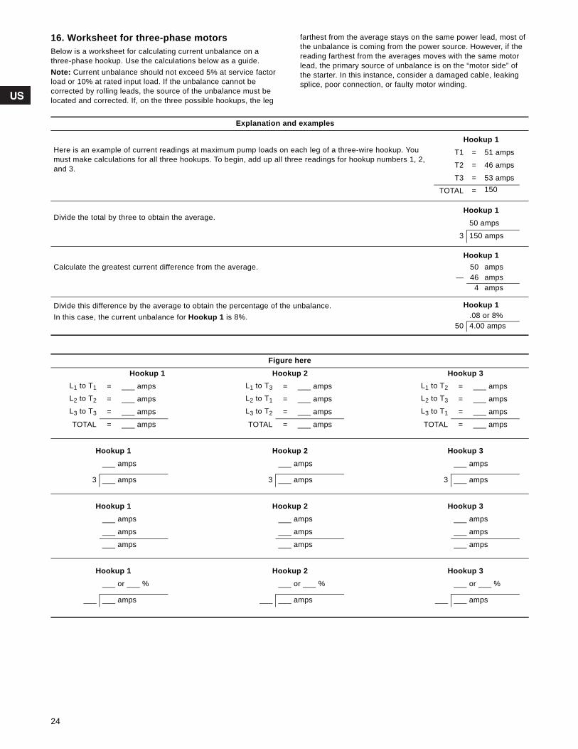
Grundfos.bk Page 24 Wednesday, March 18, 2009 10:38 AM
16. Worksheet for three-phase motorsBelow is a worksheet for calculating current unbalance on a three-phase hookup. Use the calculations below as a guide.Note: Current unbalance should not exceed 5% at service factor load or 10% at rated input load. If the unbalance cannot be corrected by rolling leads, the source of the unbalance must be located and corrected. If, on the three possible hookups, the leg
farthest from the average stays on the same power lead, most of the unbalance is coming from the power source. However, if the reading farthest from the averages moves with the same motor lead, the primary source of unbalance is on the “motor side” of the starter. In this instance, consider a damaged cable, leaking splice, poor connection, or faulty motor winding.
Explanation and examples
Here is an example of current readings at maximum pump loads on each leg of a three-wire hookup. You must make calculations for all three hookups. To begin, add up all three readings for hookup numbers 1, 2, and 3.
Hookup 1T1 = 51 amps
T2 = 46 amps
T3 = 53 amps
TOTAL = 150
Divide the total by three to obtain the average.Hookup 1
50 amps
3 150 amps
Calculate the greatest current difference from the average.Hookup 1
50 amps— 46 amps
4 amps
Divide this difference by the average to obtain the percentage of the unbalance.In this case, the current unbalance for Hookup 1 is 8%.
Hookup 1.08 or 8%
50 4.00 amps
Figure hereHookup 1 Hookup 2 Hookup 3
L1 to T1 = ___ amps L1 to T3 = ___ amps L1 to T2 = ___ ampsL2 to T2 = ___ amps L2 to T1 = ___ amps L2 to T3 = ___ ampsL3 to T3 = ___ amps L3 to T2 = ___ amps L3 to T1 = ___ amps
TOTAL = ___ amps TOTAL = ___ amps TOTAL = ___ amps
Hookup 1 Hookup 2 Hookup 3___ amps ___ amps ___ amps
3 ___ amps 3 ___ amps 3 ___ amps
Hookup 1 Hookup 2 Hookup 3___ amps ___ amps ___ amps
___ amps ___ amps ___ amps
___ amps ___ amps ___ amps
Hookup 1 Hookup 2 Hookup 3___ or ___ % ___ or ___ % ___ or ___ %
___ ___ amps ___ ___ amps ___ ___ amps
24

Grundfos.bk Page 25 Wednesday, March 18, 2009 10:38 AM
U.S.A.GRUNDFOS Pumps Corporation 17100 West 118th TerraceOlathe, Kansas 66061Phone: +1-913-227-3400 Telefax: +1-913-227-3500
CanadaGRUNDFOS Canada Inc. 2941 Brighton Road Oakville, Ontario L6H 6C9 Phone: +1-905 829 9533 Telefax: +1-905 829 9512
MéxicoBombas GRUNDFOS de México S.A. de C.V. Boulevard TLC No. 15Parque Industrial Stiva AeropuertoApodaca, N.L.C.P. 66600Phone: +52-81-8144 4000 Telefax: +52-81-8144 4010
Addresses revised 22.09.2005

Grundfos.bk Page 26 Wednesday, March 18, 2009 10:38 AM

Grundfos.bk Page 27 Wednesday, March 18, 2009 10:38 AM

www.grundfos.com
Being responsible is our foundationThinking ahead makes it possible
Innovation is the essence
L-CP-TL-003 0309 USRepl. L-CP-TL-003 1205
CR 60 Hz_US Letter_back.fm Page 28 Wednesday, March 18, 2009 1:09 PM