Definición de Opinión Pública Nicola Mateucci Diccionario Norberto Bobbio

Materials and Design 181 (2019) 107930
Contents lists available at ScienceDirect
Materials and Design
j ourna l homepage: www.e lsev ie r .com/ locate /matdes
An experimental-numerical study of the adhesive static and dynamicfriction of micro-patterned soft polymer surfaces
Alice Berardo a,1, Gianluca Costagliola b, Simone Ghio a,c, Maurizio Boscardin c,Federico Bosia b, Nicola M. Pugno a,d,e,⁎a Laboratory of Bio-Inspired & Graphene Nanomechanics, Department of Civil, Environmental and Mechanical Engineering, Università di Trento, via Mesiano, 77, I-38123 Trento, Italyb Department of Physics and “Nanostructured Interfaces and Surfaces” Inter-Departmental Centre, Università di Torino, Via P. Giuria 1, 10125 Torino, Italyc Centre for Materials and Microsystems, Fondazione Bruno Kessler, Via Sommarive 18, I-38123 Povo (Trento), Italyd School of Engineering and Materials Science, Queen Mary University of London, Mile End Road, London E1 4NS, UKe Fondazione E. Amaldi, Ket Lab, Via del Politecnico snc, 00133 Rome, Italy
H I G H L I G H T S G R A P H I C A L A B S T R A C T
• The effect of patterning on static/dy-namic friction of soft polymer surfacesis investigated experimentally and nu-merically
• Micro-patterns modify macroscopicstatic friction coefficients between -57and +20% and dynamic ones between-35 and 30%
• Calculations using an in-house devel-oped 2D Spring-Block model are ingood agreement with experimentalresults
⁎ Corresponding author at: Laboratory of Bio-Inspired &77, I-38123 Trento, Italy.
E-mail address: [email protected] (N.M. Pugno).1 Present address: C3A - Center Agriculture Food Enviro
https://doi.org/10.1016/j.matdes.2019.1079300264-1275/© 2019 The Authors. Published by Elsevier Ltd
a b s t r a c t
a r t i c l e i n f oArticle history:Received 10 May 2019Received in revised form 9 June 2019Accepted 10 June 2019Available online 11 June 2019
New possibilities have emerged in recent years, with the development of high-precision fabrication techniques,to exploit microscale surface patterning to modify tribological properties of polymeric materials. However, theeffect of surface topography, together with material mechanical parameters, needs to be fully understood toallow the design of surfaces with the desired characteristics. In this paper, we experimentally assess the effectof various types of micropatterned Polydimethylsiloxane surfaces, including anisotropic ones, on macroscopicsubstrate friction properties. We find that it is possible, through surface patterning, to modify both static and dy-namic friction coefficients of the surfaces, demonstrating the possibility of achieving tunability. Additionally, wecompare experimental observationswith the numerical predictions of a 2D Spring-Blockmodel, deriving thema-terial parameters from tests on the corresponding flat surfaces. We find a good quantitative agreement betweencalculated and measured trends for various micropattern geometries, demonstrating that the proposed numer-ical approach can reliably describe patterned surfaces when appropriate material parameters are used. The pre-sented results can further contribute to the description and understanding of the frictional effects of surfacepatterning, with the aim of achieving surfaces with extreme tunability of tribological properties.© 2019 The Authors. Published by Elsevier Ltd. This is an open access article under the CC BY-NC-ND license (http://
creativecommons.org/licenses/by-nc-nd/4.0/).
Keywords:FrictionAdhesionMicro-fabricationSpring-block model
Data availability:The raw/processed data required to reproducethesefindings cannot be shared at this time dueto technical or time limitations.
Graphene Nanomechanics, Department of Civil, Environmental andMechanical Engineering, Università di Trento, via Mesiano,
nment, University of Trento/Fondazione Edmund Mach, Via Edmund Mach, 1 - 38010 San Michele all'Adige (TN), Italy.
. This is an open access article under the CC BY-NC-ND license (http://creativecommons.org/licenses/by-nc-nd/4.0/).

2 A. Berardo et al. / Materials and Design 181 (2019) 107930
1. Introduction
Many practical and industrial applications require the controlledmodification of the tribological properties of common manufacturingmaterials, such as polymers. One approach has been to explore the pos-sibility of modifying the macroscopic friction properties of these mate-rials exploiting specific microscopic surface structures, both in dry andlubricated conditions, instead of applying surface treatments ormodify-ing the material chemistry. Recent experimental results relative to thefrictional behaviour of sliding patterned surfaces have been obtainedfor non-trivial geometric features, e.g. microstructures like grooves,dimples, pillars or honeycomb patterns [1–7]. Surface patterning hasbeen studied for a number of years, and allows accentuating hydrophilicor hydrophobic properties [8–13] or adhesive properties [14–16]. Thus,the effect of surface patterning on the frictional properties of surfaces isof particular interest, including for those applications where control ofwater-repellent or adhesive behaviour is also required.
Friction between nominally flat surfaces at macroscale is the resultof interactions at different length scales spanning from nano- tomacro-scale [17–19]. In the case ofmicropatterned surfaces, the charac-teristic lengths of the structures also come into play, so that it is difficultto separate the contributions of surface roughness, heterogeneity andpatterning, and to identify the dominant mechanisms determining theemergent frictional behaviour. Thus, theoretical and numerical model-ling must be adopted in conjunction with experimental observationsto explain the effects induced by surface textures and to predict themost suitable configurations for specific purposes.
Models addressing the effect of surface patterning on macro-scopic frictional behaviour have been developed for specific caseswith the aim of reproducing experimental results [5,20,21]. Anotheroption consists in developing a general simplified model, includingthe relevant features at the mesoscale and taking into account themicroscale by means of effective laws [22], e.g. the Frenkel-Kontorova model [23–25] that can describe the emergent transitionto superlubricity due to incommensurate lattice lengths of two slid-ing layers [26–31]. Another example is the so-called Spring-Blockmodel [32–34], which has been implemented in 1D and 2D to inves-tigate how frictional properties can be modified by hierarchical orcomplex surface textures [35,36]. In particular, it was shown thatthe model could provide useful insights on the transition betweenstatic and dynamic friction in the presence of structures that modifythe surface stress distribution at the onset of sliding. Thanks to itssimplicity, the model can provide a clear qualitative understandingof the effects taking place, but due to the adopted approximations,its reliability for precise quantitative predictions remains to be eval-uated. In [36], trends consistent with those found in experiments forsurface structures were obtained, suggesting that some effects arequite general and may depend on parameters such as shape andsize of the surface textures rather than on specific material proper-ties. In this work, one of our aims is to verify to what extent this istrue, i.e. to assess the level of reliability of the 2D Spring-Blockmodel [36] in describing frictional properties of structured surfaces.
To physically realize various surface patterns, several techniqueshave been developed and optimized in the past, including laser surfacetexturing [37–39], which can provide high precision and speed ofmanufacturing, especially for applications involving metallic surfaces.On the other hand,micromoulding techniques are a simple and effectivealternative to the high costs of laser texturing [3,40,41]. These consist incasting an elastomer using a mould formed by a lithographic technique,and thus transferring the pattern on the elastomer substrate. In thepresent work, we adopt this method to realize microscale surface tex-turing on Polydemethilsiloxane (PDMS) substrates in different shapesand sizes, including anisotropic patterns. Variable contact area fractionsare considered to account for a wide range of potential applications.Friction tests are then performed on the patterned elastomer substratesagainst a flat polycarbonate surface and results are compared to the
calculations of a 2D version of the Spring-Block model [36], evaluatingfor the first time the limits of its predictions, with the aim of providinga tool for the precise tribological design of microscopic surface texture.
2. Experimental procedure
2.1. Surface manufacturing
Surface samples are manufactured using PDMS and are realized bydirect copy of a patterned silicon substrate. PDMS is widely used in ap-plications where a precise reproduction of a surface design is required(e.g. inmicrofluidics and in vitro biology applications). The adoptedma-terial (Sylgard184) is supplied in two components: a cross-linking cur-ing agent and a pre-polymer base. Polymerization begins when the twoliquids are mixed together. The PDMS is first degassed for 30 min di-rectly after mixing and a second time 30min after deposition on the sil-icon substrate. The silicon substrate is processed in a Metal-Oxide-Semiconductor pilot line, involving soft-lithography and dry etching torealize micrometric surface structures. Before PDMS moulding, the sili-con substrate is coated with a silane Self-Assembly Monolayer to avoidsticking and to promote detachment after curing. Samples are cured at atemperature of 70 °C for 50min and PDMS samples are peeled from thesilicon substrate after cooling.
The chosen surface patterns are periodic arrangements of micro-cavities, as shown in Fig. 1. In particular, three patterns are considered,each characterized by different cavity diameter Φ, pitch distance be-tween cavities p and corresponding contact Area Fraction (AF) values,defined as the ratio between the nominal contact area of the patternedsample and the nominal contact area of the flat sample (F). The param-eters of the geometries, chosen for their simplicity of fabrication in po-tential applications, are reported in Table 1. An additional pattern isconsidered to study the influence of anisotropy (Fig. 1.5, sample S).This pattern presents elongated cavities 40 × 200 μm in size, withpitch distance py = 120 μm in the shorter direction and px = 200 μmin the longer one. Again, this geometry is chosen for its simplicity,while providing marked anisotropy. The cavities are staggered in thelonger direction. Both principal directions (x and y in Fig. 1.6) are con-sidered in friction tests.
2.2. Setup for tribological tests
To obtain both the static and dynamic friction coefficients of theaforementioned surfaces, a custom-built tribometer is used (Fig. 2). Itis composed of two main polycarbonate parts. The first component(Fig. 2.2) is formed by a tensile machine and a polished polycarbonatesurface, which is the reference sliding surface. The other component isthe sample holder and slider (enlargement in Fig. 2.1). Samples areglued on the slider, with the surface to be tested in contact with thepolycarbonate base. The slider is pulled by a double Dyneema (nearlyinextensible) wire, which is connected to the grip of the tensile ma-chine. A variable mass is placed on the top of the slider to change thenormal applied force. The tensile machine records the pulling force act-ing on the wire and transmitted by a frictionless roller, recording thefriction force generated by the sample sliding on the polycarbonatebase.
2.3. Tribological test procedure
Samples are first glued to the sample holder. Both the test surfaceand the polycarbonate base are cleaned with ethanol and dried and agiven mass is applied on the slider. The test is then performed at con-stant pulling speed of 0.2 mm/s, which is of the order of values adoptedin previous studies [42–44]. Once the detachment force is reached, cor-responding to the first peak in the load-displacement curve, the samplestarts sliding at an approximately constant force value. When this value

Fig. 1. SEM images showing details of the considered surface patterns: (1)flat surface (sample F). (2) Sample A. (3) Sample B. (4) Sample C. (5) Sample S. (6) Enlargement of a single cavityof sample S. All scale bars are equal to 20 μm.
3A. Berardo et al. / Materials and Design 181 (2019) 107930
has stabilized, the test is stopped. The dynamic friction force is taken asthe mean value during the sliding phase.
Different masses are used during the friction tests, from 1.5 g (themass of the sample holder) to about 140 g (with additional weights).Tests are repeated about ten times for each sample and mass (threesamples per pattern type) to obtain sufficient statistics. All measure-ments are carried out at room temperature.
3. Experimental results and discussion
It is known that frictional behaviour of elastomers is a complex phe-nomenon, usually governed by interfacial properties and dissipationmechanisms (e.g. see [42,45,46]). Adhesion and friction are strictly cor-related, and both can depend on sliding velocity, applied normal loadand molecular weight, but in the range of small velocities, typically be-tween 0.1 mm/s and 1 mm/s, the dependence of macroscopic frictioncoefficients on velocity is generally considered negligible [47]. In thisstudy, all tests were performed at the same sliding speed of 0.2 mm/s.Fig. 3 shows the tangential force variation as a function of time for differ-ent surface textures. The force is normalized by the static friction forceto provide a qualitative comparison on the same scale for each sample.As explained in the previous section, both the static and the dynamicfriction forces can be determined from these tests. We report one testfor each pattern type, i.e. the friction force normalized by its maximumvalue obtained in the same test, to highlight behaviour of the differentsamples. The tests show considerable stick-slip behaviour between thepolycarbonate and flat PDMS samples (Fig. 3.1), especially at the
Table 1Geometrical characteristics of considered surface patterns. Nominal Area Fraction (AF) iscalculated as the ratio between the areas of a patterned sample with respect to that of aflat surface (sample F). The pitch distances are also reported (px and py).
Sample Hole diameter Φ (μm) Hole area (μm2) px × py (μm2) Nominal AF
F – – – 1A 5 π52/4 20 × 20 0.95B 10 π102/4 15 × 15 0.65C 15 π152/4 20 × 20 0.56S – 40 × 200 220 × 120 0.67
beginning of sliding, but this effect becomes less evident for higher ap-plied loads [3,40]. The plots highlight some differences between pat-terns, especially for sample C (Fig. 3.4), for which static and dynamicfriction forces are similar, with limited stick-slip effects.
To better highlight the dependence of the friction force on the pat-tern type, Fig. 4 shows the results for different applied pressures, bothfor static and dynamic friction. Since the generalized Coulomb frictionlaw is a good approximation for the macroscopic frictional behaviourof these samples, the experimental results have been fitted using theequation T = μN + τ0A, where T is the tangential/friction force, μ isthe friction coefficient, N is the applied normal load, τ0 is the adhesiveshear strength, and A is the nominal contact area. From the fits, μ andτ0 are obtained, both for static and dynamic friction (reported inTable 2). Macroscopic friction coefficients decrease non-linearly withincreasing applied normal load. For a small or near-zero normal load, re-sults display a large standard deviation, mainly due to difficulties in set-ting identical initial conditions for all the samples (positioning on thesetup was done by hand). Conversely, the standard deviation decreasesfor increasing normal loads. This also applies to sample C, althoughsome oscillations occur.
Results obtained for sample S highlight the effect of surface patternanisotropy and sliding along two different directions. Due to the elon-gated holes, which are longer in the x direction than in the y direction,the friction force is greater when the sample slides along x, especiallyfor small loads. A similar result was found in [40], where the authorsstudied friction parallel and perpendicular to wrinkled surfaces, observ-ing that for slidingparallel andperpendicular to thewrinkles, the slidingfrictional force decreased compared to a flat surface, the greater de-crease being for the perpendicular direction.
From experimental results, one can deduce how surface patterns in-fluence the frictional behaviour of the PDMS samples. Sample A is char-acterized by the smallest cavities and larger spacing, so that its frictioncoefficients are the closest to those of the flat samples. In comparison,samples B and C display smaller friction forces as a function of the ap-plied normal load. This is partly due to a decrease of the real contactarea of the textured samples, as discussed in [3], but also to stress con-centrations around surface features and the effect of adhesion, whichhas a higher relative influence at smaller loads, especially on surfaceswith higher texture density.
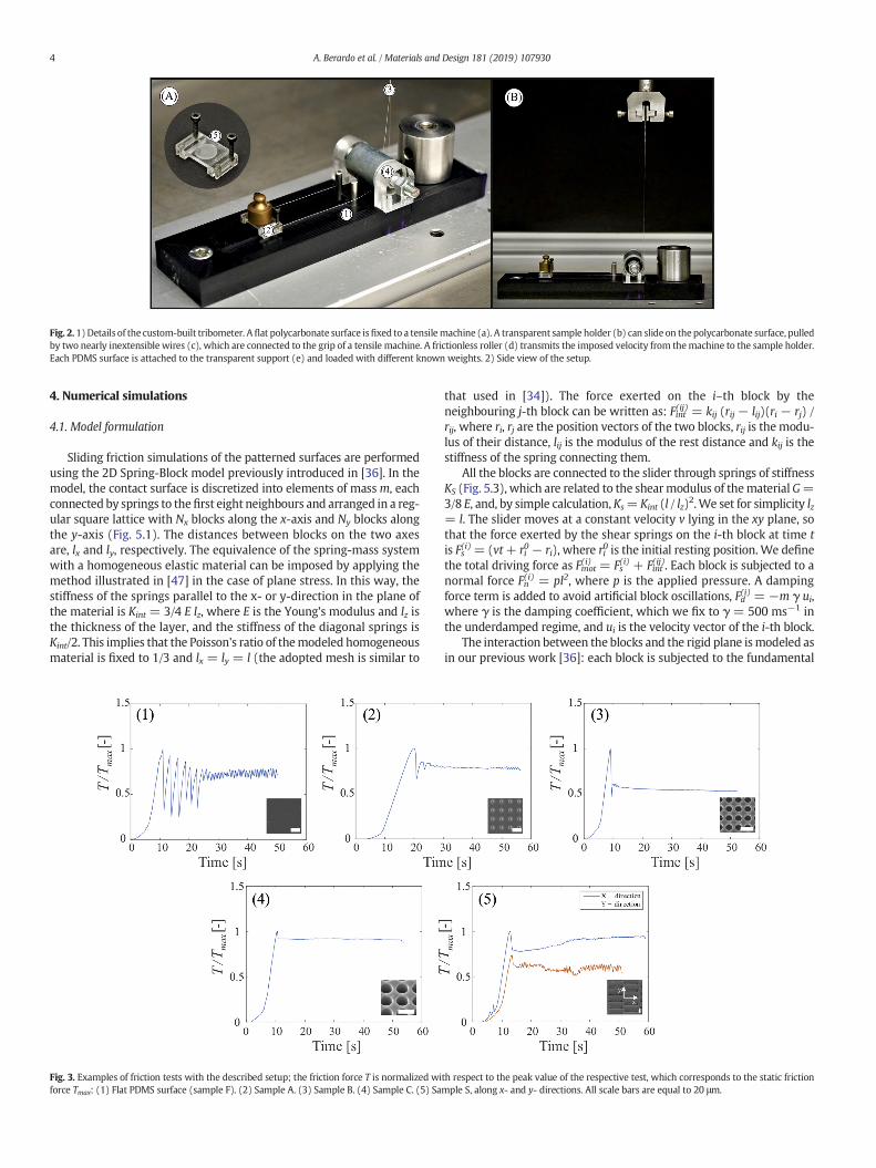
Fig. 2.1)Details of the custom-built tribometer. Aflat polycarbonate surface isfixed to a tensilemachine (a). A transparent sample holder (b) can slide on thepolycarbonate surface, pulledby two nearly inextensible wires (c), which are connected to the grip of a tensile machine. A frictionless roller (d) transmits the imposed velocity from themachine to the sample holder.Each PDMS surface is attached to the transparent support (e) and loaded with different known weights. 2) Side view of the setup.
4 A. Berardo et al. / Materials and Design 181 (2019) 107930
4. Numerical simulations
4.1. Model formulation
Sliding friction simulations of the patterned surfaces are performedusing the 2D Spring-Block model previously introduced in [36]. In themodel, the contact surface is discretized into elements of massm, eachconnected by springs to thefirst eight neighbours and arranged in a reg-ular square lattice with Nx blocks along the x-axis and Ny blocks alongthe y-axis (Fig. 5.1). The distances between blocks on the two axesare, lx and ly, respectively. The equivalence of the spring-mass systemwith a homogeneous elastic material can be imposed by applying themethod illustrated in [47] in the case of plane stress. In this way, thestiffness of the springs parallel to the x- or y-direction in the plane ofthe material is Kint = 3/4 E lz, where E is the Young's modulus and lz isthe thickness of the layer, and the stiffness of the diagonal springs isKint/2. This implies that the Poisson's ratio of themodeled homogeneousmaterial is fixed to 1/3 and lx = ly = l (the adopted mesh is similar to
Fig. 3. Examples of friction tests with the described setup; the friction force T is normalized wiforce Tmax: (1) Flat PDMS surface (sample F). (2) Sample A. (3) Sample B. (4) Sample C. (5) Sa
that used in [34]). The force exerted on the i–th block by theneighbouring j-th block can be written as: Fint(ij) = kij (rij − lij)(ri − rj) /rij, where ri, rj are the position vectors of the two blocks, rij is the modu-lus of their distance, lij is the modulus of the rest distance and kij is thestiffness of the spring connecting them.
All the blocks are connected to the slider through springs of stiffnessKS (Fig. 5.3), which are related to the shearmodulus of thematerialG=3/8 E, and, by simple calculation, Ks= Kint (l / lz)2.We set for simplicity lz= l. The slider moves at a constant velocity v lying in the xy plane, sothat the force exerted by the shear springs on the i-th block at time tis Fs(i)= (vt+ ri
0 − ri), where ri0 is the initial resting position.We definethe total driving force as Fmot
(i) = Fs(i) + Fint
(ij). Each block is subjected to anormal force Fn
(i) = pl2, where p is the applied pressure. A dampingforce term is added to avoid artificial block oscillations, Fd(i) = −m γ ui,where γ is the damping coefficient, which we fix to γ = 500 ms−1 inthe underdamped regime, and ui is the velocity vector of the i-th block.
The interaction between the blocks and the rigid plane ismodeled asin our previous work [36]: each block is subjected to the fundamental
th respect to the peak value of the respective test, which corresponds to the static frictionmple S, along x- and y- directions. All scale bars are equal to 20 μm.

Fig. 4. Experimental apparent friction (T/N) test results.Mean values are reported as dots,while the standard deviation of themean is shownwith error bars. Plots report the ratio betweenthe static or dynamic friction force (T) and the applied normal load (N) as a function of the applied nominal pressure (p= N/A, with A the total nominal sample area). The experimentaldata are fitted by using the generalized Coulomb friction relation T/N = μ + τ0/p, where μ is the static or dynamic friction coefficient, while τ0 is the adhesion force normalized by thenominal area of contact. Fitting parameters μ and τ0 are reported in Table 2. (1) Static friction coefficients of flat surfaces (samples F) and samples A, B and C. (2) Dynamic frictioncoefficients of flat surfaces (samples F) and samples A, B and C. (3) Static friction coefficients of samples S, along both x and y directions. (4) Dynamic friction coefficients of samples S,along both x and y directions.
5A. Berardo et al. / Materials and Design 181 (2019) 107930
Amontons-Coulomb (AC) friction force with local static and dynamicfriction coefficients, respectively μ s
(i) and μd(i), which are assigned ran-
domly for each block at the beginning of the simulation from a Gaussianstatistical distribution g(μ s,d
(i)) = (2πσ)−1 exp [−(μ s,d(i) − (μ s,d)m)2 / (2σs,
d2)]. (μ s,d)m denotes themean of themicroscopic friction coefficients forthe static and dynamic case, respectively, and σs,d is its standard devia-tion. Thus, the friction force on the i-th block can be described as
Table 2Linear interpolation (T/N = μ + τ0/p) parameters for experimental results and corre-sponding numerical estimations.
Sample Experimental results Numerical estimations
μ τ0 [kPa] μ τ0 [kPa]
Mean St. dev Mean St. dev Mean St. dev Mean St. dev
Static frictionF 4.76 0.73 23.45 9.24 4.780 0.013 23.44 0.06A 5.71 2.36 15.41 20.03 4.150 0.006 17.71 0.04B 2.05 0.40 24.85 7.46 3.760 0.006 9.83 0.04C 2.18 1.19 4.30 6.15 4.000 0.032 7.47 0.08Sx 2.44 1.55 9.17 12.13 3.290 0.006 10.84 0.03Sy 2.25 0.22 1.16 2.07 3.250 0.006 10.12 0.01
Dynamic frictionF 2.88 1.39 11.85 11.27 2.879 0.003 11.89 0.01A 3.75 1.64 4.02 9.47 2.864 0.002 11.17 0.01B 2.62 0.32 2.98 2.55 3.036 0.008 6.02 0.05C 1.88 0.78 1.05 2.01 3.107 0.015 4.85 0.08Sx 2.67 0.87 4.52 5.12 2.866 0.005 8.57 0.01Sy 2.14 0.16 0.09 0.84 2.851 0.005 8.60 0.03
follows: while the block is at rest, the friction force Ffr(i) opposes the
total driving force, i.e. Ffr(i) = −Fmot(i) , up to a threshold value Ffr
(i) = μ s(i)
Fn(i). When this limit is exceeded, a constant dynamic friction force op-poses the motion, whose modulus is Ffr(i) = μd(i) Fn(i). Furthermore, sinceexperimental data in this work shows non-negligible adhesion effectsin the friction force in the limit of zero pressure, a constant term isadded to both static and dynamic friction forces. Thus, the static frictionthreshold for the i-th block is Ffr(i) = μ s
(i) Fn(i) + Fas, where Fas is the same
for all blocks and includes all the possible adhesion effects in the staticphase. The dynamic friction force is Ffr(i) = Fad + μd(i) Fn(i), where Fad isthe adhesion term in the dynamic phase. In the case of patterned sur-faces, areas corresponding to cavities are attributed friction coefficientsequal to zero.
This model is an approximation of friction/adhesion effects, andothermicroscopic formulations are possible [19]. However, it is the sim-plest way to account for adhesion effects without adding specific detailsof themicroscopic structure. Our aim is to test its validity limits compar-ing it with experimental results.
The motion of a block i is described by Newton's equation:
m a ið Þ ¼ Σ j Fintijð Þ þ Fs
ið Þ þ Fdið Þ þ Ffr
ið Þ
where a(i) is the block acceleration. The overall system of equations canbe solved using a fourth-order Runge-Kutta algorithm to find themodeltime evolution.
From the equation of motion of all blocks the total tangential frictionforce can be calculated through the total force exerted by the slider, i.e. T(t) = ΣiFs
(i)(t), which corresponds to that measured in experiments. A

Fig. 5. (1) Schematic of the 2D Spring-Blockmodel with the notation used in the text. Mesh of the internal springs on the surface (shear springs are not shown). (2) Example of a patternedsurface, where themain sliding direction is set to α=0°. (3) Side view showing the slider moving at constant velocity v, pulling the sample through shear springs. (4) Typical simulationoutputs, showing the time evolution of the friction coefficient for different types of samples.
6 A. Berardo et al. / Materials and Design 181 (2019) 107930
typical behaviour of T as a function of time is shown in Fig. 5.4. From thiscurve it is possible to extract the static friction force Tmax=maxt T(t), i.e.the first force peak. To account for statistical effects, the simulations areiterated various times, extracting each time new random local frictioncoefficients and determining a statistical average of any observable.The integration time step is 10−8 s, which is sufficient to reduce integra-tion errors below the statistical uncertainty due to the model iterations[36].
4.2. Model parameters
The numerical model contains a number of parameters that need tobe tuned by fitting experimental data, although some degree of approx-imation is inevitable since experimental conditions cannot be replicatedexactly. For example, the Poisson's ratio of themodel is constrained to 1/3 due to the requirement of equivalence with a continuous material,while the PDMS real value is closer to 0.5. Sincemesh deformations dur-ing the simulation are less than 1% of the discretization length, we as-sume that this approximation is not influential. Although the squaremesh is not isotropic, we have verified that for a non-patterned surface,results of macroscopic friction coefficients do not depend on the slidingangle. Moreover, averaging over random orientations is required to ac-count for the uncertainty on the experimental sliding angle (as ex-plained below).
The slider velocity, the applied pressure, the material density andYoung's modulus are taken from experimental values. Thus, the massof the block is m = ρ l3, with ρ = 1.012 g/cm3. The Young's modulusis E = 0.8 MPa [46], and the applied pressure varies between 3 kPaand 25 kPa. The modulus of the slider velocity is v = 0.2 mm/s. Inorder to reduce the computational times, simulation time scales havebeen reduced with respect to those used in the experiments (seeFig. 5.4) by adjusting the arbitrary parameter lz. However, we have ver-ified that modifications on friction coefficients due to a reduced time
scale are smaller than the statistical uncertainty on model results. Thesliding direction with respect to the (x,y) orientation is randomly cho-sen at each simulation at an angle α, to account for the uncertainty inthe sliding direction in experiments. Thus, the velocity vector of theslider is v = (v cos(α), v sin(α)). For flat and patterned samples A, B,C the angle is chosen with a uniform distribution in the range [0°,90°], which is sufficient to emulate the experimental setup due to thesymmetry of the samples. For anisotropic samples S, which are designedwith a precise sliding direction (α=0 for S along the x-axis andα=90°for sliding along the y-axis), the uncertainty is reduced and the angle ischosen within a range [−10°, 10°] around the nominal sliding angle.
The local friction coefficients and adhesion force of themodel are ob-tained by fitting the experimental data for a flat (non-patterned) sur-face, i.e. we set these local parameters to obtain, in the flat case, thesame global friction coefficients and total adhesion found in experi-ments. The average values and standard deviations are μs)m = 5.5, σs
=0.195 and μd)m =2.9, σd =0.15 for the local static and dynamic fric-tion coefficients, respectively. The adhesion terms are Fas/l2=23.45 kPaand Fad/l
2 = 11.60 kPa.The springmeshdiscretization length isfixed to l=5 μm,which cor-
responds to the smallest feature of the experimental surface structures.The total number of blocks required tomatch the size of the experimen-tal sample would be very high, but it is not necessary to reproduce theentire specimen. As discussed in [36] the resulting qualitative behaviouris not influenced by the number of blocks and the only effect ofdiscretization is the decrease of the macroscopic static friction coeffi-cients. Since there is already a set of free parameters, e.g. local frictioncoefficients and the adhesion, which need to be tuned in order tomatch the macroscopic coefficients with the experimental one, it isequivalent to fix a smaller number of blocks and to consequently tunethe other parameters. Thus, the lateral number of blocks is Nx = Ny =85, which allows to simulate all the different samples with the samemesh while adequately modelling the cavity geometries.

7A. Berardo et al. / Materials and Design 181 (2019) 107930
We approximate the circular holes by means of squares withsides of the same length as the circle diameter and the same spacingsbetween neighbouring cavities. Although the numerical model doesnot replicate the exact area and geometry of the holes, simulationsusing with a finer discretization mesh (i.e. reduced discretizationlength), which better approximate the circular shape, do not providesubstantially different results. The same local friction coefficients ofthe flat surfaces are adopted for the regions of the patterned samplesin contact with the substrate. In order to compare the numericalsimulations with the experimental results, data must be normalizedwith respect to the total normal force N= ΣiFn
(i), so that comparisonsare made for T/N, i.e. the macroscopic friction coefficient, as a func-tion of pressure p.
5. Discussion
In Figs. 6 and 7, we show the comparison between experimental andnumerical results for static anddynamic friction forces, respectively, as afunction of the applied normal load. For both series of data, results arefitted using a linear interpolation (red line for experimental and greenfor numerical), as T= A·τ0 + μ·N. Results obtained for the linear inter-polation are also reported in Table 2.
The parameters of the fitting curve display a dependence on the con-sidered surface structure. Once the input model parameters are tunedusing experimental data for a flat surface, the numerical calculationsfor static friction coefficients appear to be in good agreement with ex-perimental results. The model is able to reproduce the correct range offriction values for the different A, B, C samples and for the anisotropicpatterns Sx, Sy. This means that, despite the approximations, themodel correctly accounts for the stress concentrations occurring at theedges of these structures and is able to capture the underlying mecha-nisms of the transition from the static to the dynamic phase in the
Fig. 6. Static friction force T as a function of the applied normal load (N): experimental data ((yellow dotted line). (1) Flat surface (sample F); (2) A sample; (3) B sample; (4) C sample;(For interpretation of the references to color in this figure legend, the reader is referred to the
presence of surface features. A good quantitative description of the be-haviour of samples A and Sx is found. These are also the samples witha closer match for τ0 values, while for other samples the calculated var-iations are slightly smaller.
This can be explained by considering that the adhesion term foundin experiments is actually the sum of various effects not directly in-cluded in the model, e.g. deformation of the pattern geometries, varia-tion of the effective contact area during sliding, and possible “suction-cup” effects. Thus, the model is less reliable from the quantitativepoint of view when these factors become more influential.
Numerical dynamic friction coefficients display smaller variationswith respect to the experimental values for all types of patterns, andthe calculated macroscopic adhesion term is proportional to the effec-tive contact area. This is only partially true for experimental data. As ex-pected, the current formulation of the model is less accurate indescribing this phase of the sliding, probably mainly due to the implicitmodel assumption that pattern shapes remain unvaried during sliding,which may not be strictly true for a soft material like PDMS.
In Fig. 8, we analyse the results of thefit of Table 2 as a function of thecorresponding Area Fraction (AF) of the different surface structures. Ex-perimental results are correlated to this parameter by adding the curveT= Tflat·AF (where Tflat is the fitting data for the flat surface) to the plot.Friction coefficients and adhesion terms display a linearly decreasingtrendwithAF for all isotropic patterns and for the anisotropic Sx pattern,i.e. when the larger side is aligned with the sliding direction. Results forthe Sy pattern appear as outliers in the fit of τ0. This confirms that areavariations due to PDMS deformation influence the global value of τ0 inthe experimental results for different sliding directions on asymmetricpatterns, Except for this, both numerical and experimental results areconsistent with a three-term friction law T = μ N + a AF+ b, where aand b are constants, so that the adhesion term corresponds to τ0 = aAF+ b for a fixed area fraction [47,48].
blue circles), linear fit (red line), numerical simulations (green line), AF prediction curve(5) S sample - sliding along the x direction; (6) S sample - sliding along the y direction.web version of this article.)

Fig. 7.Dynamic friction force T as a function of the applied normal load (N): experimental data (blue circles), linearfit (red line), numerical simulations (green line), AF prediction curve fit(yellow dotted line). (1) Flat surface (sample F); (2) A sample; (3) B sample; (4) C sample; (5) S sample - sliding along the x direction; (6) S sample - sliding along the y direction. (Forinterpretation of the references to color in this figure legend, the reader is referred to the web version of this article.)
8 A. Berardo et al. / Materials and Design 181 (2019) 107930
Overall, results show that the 2D Spring-Blockmodel can be used fora qualitative description of the dynamic friction behaviour, and for aquantitative description of the static friction behaviour of elasticmicropatterned surfaces. The necessary tuning of model parameterscan be performed once and for all for a given material system andthese remain valid for varying surface patterns, at least if the same sur-face preparation procedure is adopted. The current formulation is reli-able for the static phase in a regime of slow sliding, small-intermediate pressures and negligible effects due to pattern deforma-tions during the sliding.
Fig. 8. Experimental and numerical friction coefficient dependence on the area fraction (AF): colines are thefits of these parameters), μ and τ0 obtainedwith numerical simulations and the samcoefficient; (3) dynamic friction coefficient; (4) dynamic adhesion coefficient. Due to approxim0.57 (sample B), 0.46 (sample C) and 0.72 (sample Sx and Sy). (For interpretation of the refere
6. Conclusions
In conclusion, we have presented a combined experimental and nu-merical study on static and dynamic friction of micro-patterned PDMSsurfaces on a flat substrate. Experimental results were performed with acustom-made tribometer that allowed the evaluation of friction forcesat a constant sliding velocity and for varying normal applied loads. Vari-ous types of simplemicro-patterns were considered, from equally spacedcircular cavities to an array of elongated cavities, to evaluate the role ofpattern spacing and anisotropy. Results show good repeatability and
mparison between μ and τ0 obtained from the linear fit of the experimental data (the rede parameters foundassuming T= Tflat ·AF. (1) Static friction coefficient; (2) static adhesionations in the numerical model, the AF of the samples is slightly different: 0.94 (sample A),nces to color in this figure legend, the reader is referred to the web version of this article.)

9A. Berardo et al. / Materials and Design 181 (2019) 107930
consistency, with a decrease of macroscopic apparent friction coefficientsas a function applied normal load. Anisotropic patterns generate a varia-tion of friction forces of up to 300% depending on the sliding directionin the plane, thus allowing the generation of directionally-tuned friction.Numerical calculations using the 2D Spring-Block model, modified to in-clude adhesion, show considerable agreement with experimental results,correctly reproducing normal load dependence and static friction coeffi-cient absolute values, both for isotropic and anisotropic patterns. Resultsprovide further evidence of the reliability of the presented model in thecase of friction of 2D patterned surfaces. This can be of great interest forthe calculation of frictional properties of surface patterns, limiting theneed for experimental tests, or for the design of novel surface texture de-signs for applications, which can enable control and tuning of their fric-tional and adhesive properties.
Abbreviations
PDMS polydemethilsiloxaneAF Area Fraction
Funding sources
EU H2020 Graphene Flagship Core 2 No. 785219 (WP14“Composites”).
EU H2020 FET Proactive “Neurofibres” grant No. 732344.Italian Ministry of Education, University and Research (MIUR) “De-
partments of Excellence” grant L.232/2016.Italian Ministry of Education, University and Research (MIUR)
ARS01-01384-PROSCAN Grant.ItalianMinistry of Education, University and Research (MIUR) PRIN-
20177TTP3S Grant.Fondazione San Paolo “Metapp” Grant n. CSTO160004.
CRediT authorship contribution statement
Alice Berardo: Investigation, Methodology, Writing - original draft,Writing - review & editing. Gianluca Costagliola: Investigation, Meth-odology, Writing - original draft, Writing - review & editing. SimoneGhio: Investigation, Methodology. Maurizio Boscardin: Investigation,Methodology. Federico Bosia: Investigation,Methodology, Supervision,Writing - review & editing. Nicola M. Pugno: Conceptualization, Re-sources, Funding acquisition, Investigation, Methodology, Supervision,Writing - review & editing.
Acknowledgments
Computational resources were provided by the C3S centre at theUniversity of Torino (c3s.unito.it) and hpc@polito at the Politecnico diTorino (www.hpc.polito.it).
References
[1] M.J. Baum, L. Heepe, E. Fadeeva, S.N. Gorb, Dry friction of microstructured polymersurfaces inspired by snake skin, Beilstein J. Nanotechnol. 5 (2014) 1091–1103,https://doi.org/10.3762/bjnano.5.122.
[2] C. Greiner, M. Schäfer, U. Popp, P. Gumbsch, Contact splitting and the effect of dim-ple depth on static friction of textured surfaces, ACS Appl. Mater. Interfaces 6 (2014)7986–7990, https://doi.org/10.1021/am500879m.
[3] B. He, W. Chen, Q. Jane Wang, Surface texture effect on friction of a microtexturedpoly(dimethylsiloxane) (PDMS), Tribol. Lett. 31 (2008) 187–197, https://doi.org/10.1007/s11249-008-9351-0.
[4] N. Li, E. Xu, Z. Liu, X. Wang, L. Liu, Tuning apparent friction coefficient by controlledpatterning bulk metallic glasses surfaces, Sci. Rep. 6 (2016) 1–9, https://doi.org/10.1038/srep39388.
[5] S. Maegawa, F. Itoigawa, T. Nakamura, Effect of surface grooves on kinetic friction ofa rubber slider, Tribol. Int. 102 (2016) 326–332, https://doi.org/10.1016/j.triboint.2016.05.019.
[6] B. Murarash, Y. Itovich, M. Varenberg, Tuning elastomer friction by hexagonal sur-face patterning, Soft Matter 7 (2011) 5553, https://doi.org/10.1039/c1sm00015b.
[7] H.T. Tramsen, S.N. Gorb, H. Zhang, P. Manoonpong, Z. Dai, L. Heepe, Inversion of fric-tion anisotropy in a bio-inspired asymmetrically structured surface, J. R. Soc. Inter-face 15 (2018) 0629, https://doi.org/10.1098/rsif.2017.0629.
[8] S. Ghio, G. Paternoster, R. Bartali, P. Belluti,M. Boscardin,N.M. Pugno, Fast and large areafabrication of hierarchical bioinspired superhydrophobic silicon surfaces, J. Eur. Ceram.Soc. 36 (2015) 2363–2369, https://doi.org/10.1016/j.jeurceramsoc.2016.01.041.
[9] S.M. Hsu, Y. Jing, D. Hua, H. Zhang, Friction reduction using discrete surface textures:principle and design, J. Phys. D. Appl. Phys. 47 (2014), 335307. https://doi.org/10.1088/0022-3727/47/33/335307.
[10] Y.C. Jung, B. Bhushan, Contact angle, adhesion and friction properties of micro-andnanopatterned polymers for superhydrophobicity, Nanotechnology 17 (2006)4970–4980, https://doi.org/10.1088/0957-4484/17/19/033.
[11] U. Pettersson, S. Jacobson, Friction andwear properties of micro textured DLC coatedsurfaces in boundary lubricated sliding, Tribol. Lett. 17 (2004) 553–559, https://doi.org/10.1023/B:TRIL.0000044504.76164.4e.
[12] Z. Yoshimitsu, A. Nakajima, T. Watanabe, K. Hashimoto, Effects of surface structureon the hydrophobicity and sliding behavior of water droplets, Langmuir 18 (2002)5818–5822, https://doi.org/10.1021/la020088p.
[13] L. Zhai, M.C. Berg, F.Ç. Cebeci, Y. Kim, J.M. Milwid, M.F. Rubner, R.E. Cohen, Patternedsuperhydrophobic surfaces: toward a synthetic mimic of the Namib Desert beetle,Nano Lett. 6 (2006) 1213–1217, https://doi.org/10.1021/nl060644q.
[14] L. Brely, F. Bosia, N.M. Pugno, The influence of substrate roughness, patterning, cur-vature, and compliance in peeling problems, Bioinspir. Biomim. 14 (2018) 5509,https://doi.org/10.1088/1748-3190/aaa0e5.
[15] H. Zeng, N. Pesika, Y. Tian, B. Zhao, Y. Chen, M. Tirrell, K.L. Turner, J.N. Israelachvili,Frictional adhesion of patterned surfaces and implications for gecko and biomimeticsystems, Langmuir 25 (2009) 7486–7495, https://doi.org/10.1021/La900877h.
[16] M. Urbakh, J. Klafter, D. Gourdon, J.N. Israelachvili, The nonlinear nature of friction,Nature 430 (6999) (2004) 525–528, https://doi.org/10.1038/nature02750.
[17] B.N.J. Persson, Sliding Friction: Physical Principles and Applications, 2nd ed. SpringerBerlin Heidelberg, Berlin, Heidelberg, 2000 https://doi.org/10.1007/978-3-662-04283-0.
[18] M. Nosonovsky, B. Bhushan, Multiscale friction mechanisms and hierarchical sur-faces in nano- and bio-tribology, Mater. Sci. Eng. R. Rep. 58 (2007) 162–193,https://doi.org/10.1016/j.mser.2007.09.001.
[19] A. Vakis, V.A. Yastrebov, J. Scheibert, L. Nicola, D. Dini, C. Minfray, A. Almqvist, M.Paggi, S. Lee, G. Limbert, J.F.Molinari, G. Anciaux, S. Echeverri Restrepo, A. Papangelo,A. Cammarata, P. Nicolini, R. Aghababaei, C. Putignano, S. Stupkiewicz, J. Lengiewicz,G. Costagliola, F. Bosia, R. Guarino,N.M. Pugno, G. Carbone,M.H.Müser,M. Ciavarella,Modeling and simulation in tribology across scales: an overview, Tribol. Int. 125(2018) 169–199. doi.org/https://doi.org/10.1016/j.triboint.2018.02.005.
[20] A. Filippov, S.N. Gorb, Frictional-anisotropy-based systems in biology: structural diver-sity and numerical model, Sci. Rep. 3 (2013) 1–6, https://doi.org/10.1038/srep01240.
[21] D.T. Nguyen, S. Ramakrishna, C. Fretigny, N.D. Spencer, Y. Le Chenadec, A.Chateauminois, Friction of rubber with surfaces patterned with rigid spherical as-perities, Tribol. Lett. 49 (2013) 135–144, https://doi.org/10.1007/s11249-012-0052-3.
[22] A. Vanossi, N. Manini, M. Urbakh, S. Zapperi, E. Tosatti, Colloquium: modeling fric-tion: from nanoscale to mesoscale, Rev. Mod. Phys. 85 (2013) 529–552, https://doi.org/10.1103/RevModPhys.85.529.
[23] U. Dehlinger, Zur Theorie der Rekristallisation reiner Metalle, Ann. Phys. 394 (1929)749–793, https://doi.org/10.1002/andp.19293940702.
[24] T. Kontorova, J. Frenkel, On the theory of plastic deformation and twinning, I.,Zhurnal Eksp. I Teor. Fiz. 8 (1938) 89–95.
[25] O.M. Braun, Y.S. Kivshar, The Frenkel-KontorovaModel: Concepts, Methods, and Ap-plications, Springer-Verlag, Berlin, 2004https://doi.org/10.1007/978-3-662-10331-9.
[26] M. Peyrard, S. Aubry, Critical behaviour at the transition by breaking of analyticity inthe discrete Frenkel-Kontorova model, J. Phys. C Solid State Phys. 16 (1983)1593–1608, https://doi.org/10.1088/0022-3719/16/9/005.
[27] M. Hirano, K. Shinjo, Atomistic locking and friction, Phys. Rev. B 14 (1990)11837–11851, https://doi.org/10.1103/PhysRevB.41.11837.
[28] P.E. Sheehan, C.M. Lieber, Nanotribology and nanofabrication of MoO3 structures byatomic force microscopy, Science 272 (1996) 1158–1161, https://doi.org/10.1126/science.272.5265.1158.
[29] M. Dienwiebel, G.S. Verhoeven, N. Pradeep, J.W.M. Frenken, J.A. Heimberg, H.W.Zandbergen, Superlubricity of graphite, Phys. Rev. Lett. 92 (2004), 126101. https://doi.org/10.1103/PhysRevLett.92.126101.
[30] D.Mandelli, A. Vanossi, M. Invernizzi, S. Paronuzzi, N. Manini, E. Tosatti, Superlubric-pinned transition in sliding incommensurate colloidal monolayers, Phys. Rev. B:Condens. Matter Mater. Phys. 92 (2015) 134306, https://doi.org/10.1103/PhysRevB.92.134306.
[31] J. Norell, A. Fasolino, A.S. De Wijn, Emergent friction in two-dimensional Frenkel-Kontorova models, Phys. Rev. E 94 (2016), 023001. https://doi.org/10.1103/PhysRevE.94.023001.
[32] R. Burridge, L. Knopoff, Model and theoretical seismicity, Bull. Seismol. Soc. Am. 57(1967) 341–371.
[33] O.M. Braun, I. Barel, M. Urbakh, Dynamics of transition from static to kinetic friction,Phys. Rev. Lett. 103 (2009) 4301, https://doi.org/10.1103/PhysRevLett.103.194301.
[34] J. Trømborg, J. Scheibert, D.S. Amundsen, K. Thøgersen, A. Malthe-Sørenssen, Transi-tion from static to kinetic friction: insights from a 2D model, Phys. Rev. Lett. 107(2011) 4301, https://doi.org/10.1103/PhysRevLett.107.074301.
[35] G. Costagliola, F. Bosia, N.M. Pugno, Static and dynamic friction of hierarchical sur-faces, Phys. Rev. E 94 (2016) 1–10, https://doi.org/10.1103/PhysRevE.94.063003.
[36] G. Costagliola, F. Bosia, N.M. Pugno, A 2-D model for friction of complex anisotropicsurfaces, J. Mech. Phys. Solids 112 (2018) 50–65, https://doi.org/10.1016/j.jmps.2017.11.015.

10 A. Berardo et al. / Materials and Design 181 (2019) 107930
[37] A. Erdemir, Review of engineered tribological interfaces for improved boundary lu-brication, Tribol. Int. 38 (2005) 249–256, https://doi.org/10.1016/j.triboint.2004.08.008.
[38] I. Etsion, Improving tribological performance of mechanical components by lasersurface texturing, Tribol. Lett. 17 (2004) 733–737, https://doi.org/10.1007/s11249-004-8081-1.
[39] R. Ranjan, D.N. Lambeth, M. Tromel, P. Goglia, Y. Li, Laser texturing for low-flying-heightmedia, J. Appl. Phys. 69 (1991) 5745–5747, https://doi.org/10.1063/1.347908.
[40] C.J. Rand, A.J. Crosby, Friction of soft elastomeric wrinkled surfaces, J. Appl. Phys. 106(2009) 49131–49134, https://doi.org/10.1063/1.3226074.
[41] J. Yu, S. Chary, S. Das, J. Tamelier, K.L. Turner, J.N. Israelachvili, Friction and adhesionof gecko-inspired PDMS flaps on rough surfaces, Langmuir 28 (2012) 11527–11534,https://doi.org/10.1021/la301783q.
[42] S. Bistac, A. Galliano, Nano and macro tribology of elastomers, Tribol. Lett. 18 (2005)21–25, https://doi.org/10.1007/s11249-004-1701-y.
[43] A. Galliano, S. Bistac, J. Schultz, Adhesion and friction of PDMS networks: molecularweight effects, J. Colloid Interface Sci. 265 (2003) 372–379, https://doi.org/10.1016/S0021-9797(03)00458-2.
[44] R. Sahli, G. Pallares, C. Ducottet, I.E. Ben Ali, S. Al Akhrass, M. Guibert, J. Scheibert,Evolution of real contact area under shear and the value of static friction of soft ma-terials, Proc. Natl. Acad. Sci. (2018), 201706434. https://doi.org/10.1073/pnas.1706434115.
[45] G. Carbone, B. Lorenz, B.N.J. Persson, A. Wohlers, Contact mechanics and rubber fric-tion for randomly rough surfaces with anisotropic statistical properties, Eur. Phys. J.E 29 (2009) 275–284, https://doi.org/10.1140/epje/i2009-10484-8.
[46] Y.S. Yu, Y.P. Zhao, Deformation of PDMS membrane and microcantilever by a waterdroplet: comparison between Mooney-Rivlin and linear elastic constitutive models,J. Colloid Interface Sci. 332 (2009) 467–476, https://doi.org/10.1016/j.jcis.2008.12.054.
[47] A. Vernes, S. Eder, G. Vorlaufer, G. Betz, On the three-term kinetic friction law innanotribological systems, Faraday Discuss. 156 (2012) 173–196, https://doi.org/10.1039/c2fd00120a.
[48] S.J. Eder, G. Feldbauer, D. Bianchi, U. Cihak-Bayr, G. Betz, A. Vernes, Applicability ofmacroscopic wear and friction laws on the atomic length scale, Phys. Rev. Lett.115 (2) (2015)https://doi.org/10.1103/PhysRevLett.115.025502.