MINERAL INSULATED CABLE PRECISION DRILLING MACHINE · MACHINE 1 Scope The Precision Drilling...
7
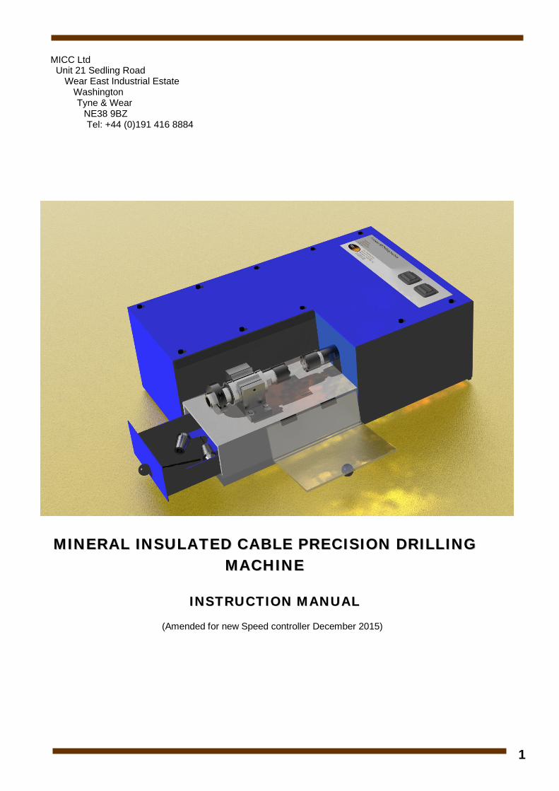
1 MICC Ltd Unit 21 Sedling Road Wear East Industrial Estate Washington Tyne & Wear NE38 9BZ Tel: +44 (0)191 416 8884 MINERAL INSULATED CABLE PRECISION DRILLING MACHINE INSTRUCTION MANUAL (Amended for new Speed controller December 2015)
Transcript of MINERAL INSULATED CABLE PRECISION DRILLING MACHINE · MACHINE 1 Scope The Precision Drilling...
1
MICC Ltd Unit 21 Sedling Road
Wear East Industrial Estate Washington
Tyne & Wear NE38 9BZ
Tel: +44 (0)191 416 8884
MMIINNEERRAALL IINNSSUULLAATTEEDD CCAABBLLEE PPRREECCIISSIIOONN DDRRIILLLLIINNGG MMAACCHHIINNEE
IINNSSTTRRUUCCTTIIOONN MMAANNUUAALL (Amended for new Speed controller December 2015)
2
MINERAL INSULATED CABLE PRECISION DRILLING MACHINE
1 Scope The Precision Drilling machine complements the M.I. Thermocouple Welding Machine. The Drilling Machine is designed to remove the insulation from the end of a prepared sample of M.I. cable in order to facilitate a complete welded measurement junction. The insulation is removed along with a section of conductor by drilling the end of the cable precisely to the required depth. The machine must cleanly cut away the conductors without twisting them together at the same time as removing the insulation.
1.1 Physical Construction – The Drilling Machine consists principally of a thyristor controlled DC 250W motor that can run up to 3000 rpm. This motor drives a precisely mounted ER16 Collet extension/holder, which accommodates the various drills. The collet extension is carried by two ball bearing pedestal blocks precisely centrally aligned with a second collet extension. This second collet extension is mounted in a linear bearing set allowing forward movement without radial displacement. Both sets of bearings are mounted on a 2” x 4” Aluminium box section, which is further mounted on a ½” thick Aluminium base plate. These last two components ensure maximum rigidity of the aligned collet holders.
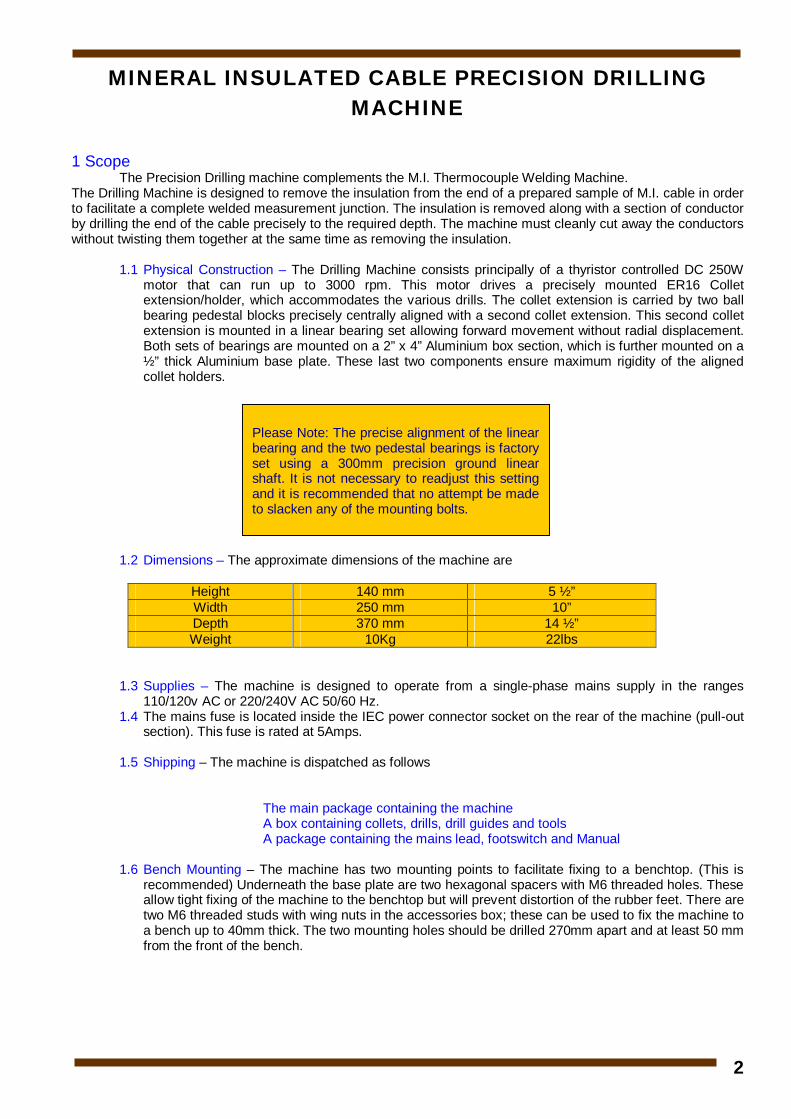
1.2 Dimensions – The approximate dimensions of the machine are
Height 140 mm 5 ½” Width 250 mm 10” Depth 370 mm 14 ½” Weight 10Kg 22lbs
1.3 Supplies – The machine is designed to operate from a single-phase mains supply in the ranges 110/120v AC or 220/240V AC 50/60 Hz.
1.4 The mains fuse is located inside the IEC power connector socket on the rear of the machine (pull-out section). This fuse is rated at 5Amps.
1.5 Shipping – The machine is dispatched as follows
The main package containing the machine A box containing collets, drills, drill guides and tools A package containing the mains lead, footswitch and Manual
1.6 Bench Mounting – The machine has two mounting points to facilitate fixing to a benchtop. (This is
recommended) Underneath the base plate are two hexagonal spacers with M6 threaded holes. These allow tight fixing of the machine to the benchtop but will prevent distortion of the rubber feet. There are two M6 threaded studs with wing nuts in the accessories box; these can be used to fix the machine to a bench up to 40mm thick. The two mounting holes should be drilled 270mm apart and at least 50 mm from the front of the bench.
Please Note: The precise alignment of the linear bearing and the two pedestal bearings is factory set using a 300mm precision ground linear shaft. It is not necessary to readjust this setting and it is recommended that no attempt be made to slacken any of the mounting bolts.
3
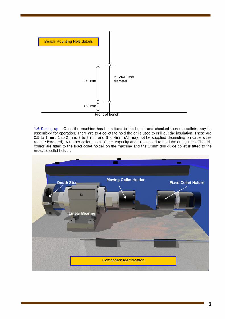
1.6 Setting up – Once the machine has been fixed to the bench and checked then the collets may be assembled for operation. There are to 4 collets to hold the drills used to drill out the insulation. These are 0.5 to 1 mm, 1 to 2 mm, 2 to 3 mm and 3 to 4mm (All may not be supplied depending on cable sizes required/ordered). A further collet has a 10 mm capacity and this is used to hold the drill guides. The drill collets are fitted to the fixed collet holder on the machine and the 10mm drill guide collet is fitted to the movable collet holder.
Linear Bearing
Moving Collet Holder Fixed Collet Holder Depth Stop
Component Identification
>50 mm
270 mm 2 Holes 6mm diameter
Front of bench
Bench-Mounting Hole details
4
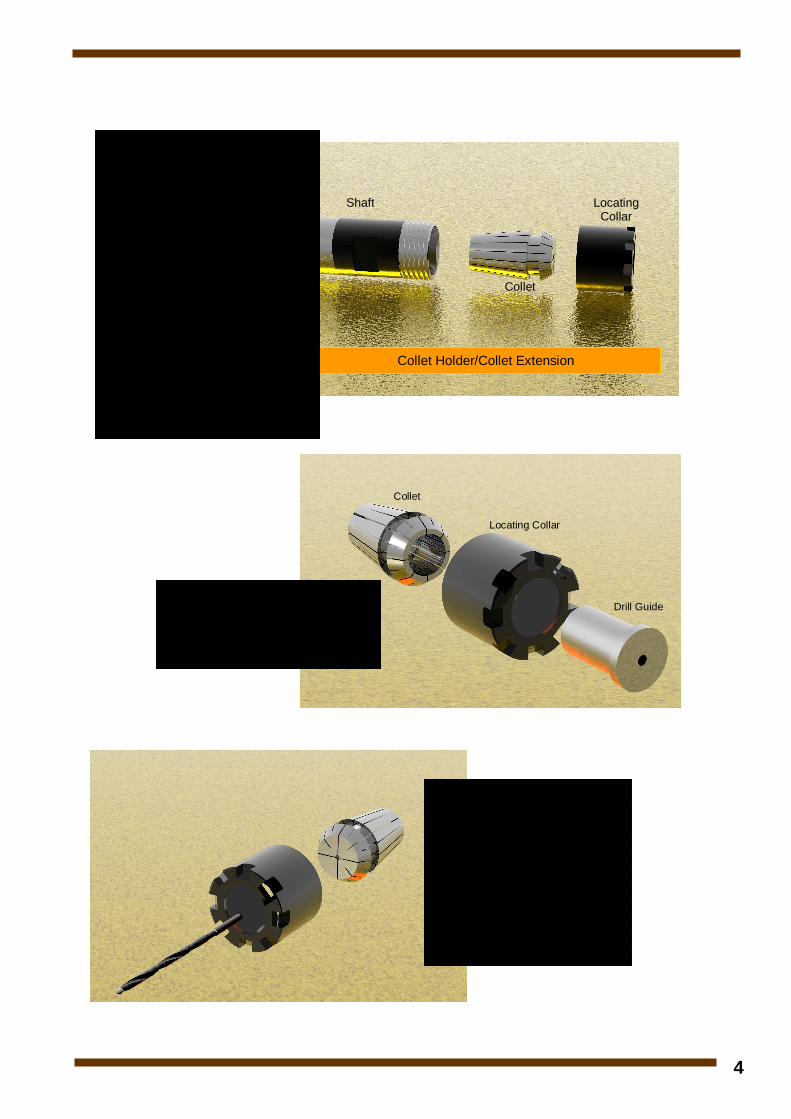
Locating Collar
Collet
Shaft
Collet Holder/Collet Extension
Fitting collets into collet holders.
The collet holder is designed to release the collet from the shaft when the locating collar is unscrewed. The collet fits into a lip inside the locating collar. To fit a collet, hold the locating collar in one hand and offer up the collet at an angle twisting it into the locating collar. (Do not force it in) When the collet is properly in place the front face will align with the front of the locating collar. The locating collar and collet will then screw into the shaft. Once this technique is mastered it is very easy to fit and remove collets.
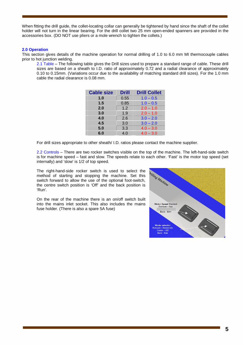
Collet
Locating Collar
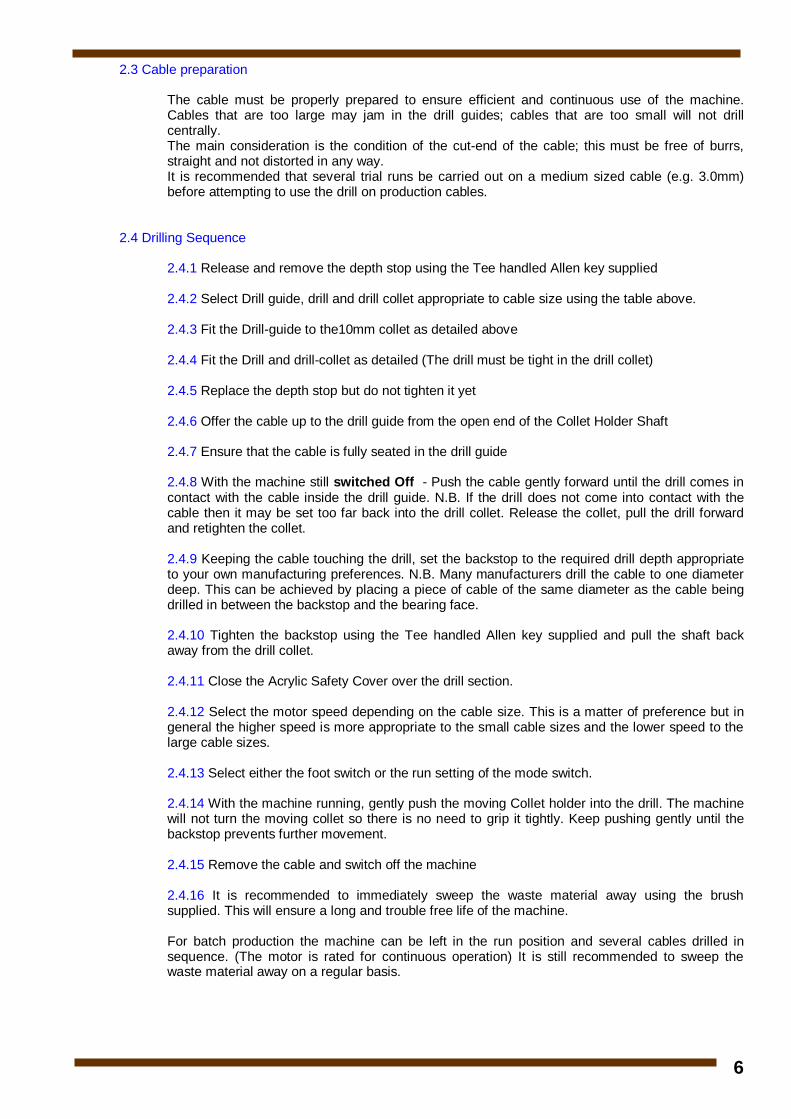
Drill Guide For the moving Collet holder the appropriate drill guide can be inserted into the collet prior to screwing the locating collar into place
For the fixed Collet Holder the required drill can be inserted into the collet prior to screwing the locating collar into place. Please note: - DO NOT insert a drill larger than the collet upper size limit into the collet - this will damage the collet and cause misalignment. Always use the appropriate collet for the drill size used.
5
When fitting the drill guide, the collet-locating collar can generally be tightened by hand since the shaft of the collet holder will not turn in the linear bearing. For the drill collet two 25 mm open-ended spanners are provided in the accessories box. (DO NOT use pliers or a mole wrench to tighten the collets.) 2.0 Operation This section gives details of the machine operation for normal drilling of 1.0 to 6.0 mm MI thermocouple cables prior to hot junction welding.
2.1 Table – The following table gives the Drill sizes used to prepare a standard range of cable. These drill sizes are based on a sheath to I.D. ratio of approximately 0.72 and a radial clearance of approximately 0.10 to 0.15mm. (Variations occur due to the availability of matching standard drill sizes). For the 1.0 mm cable the radial clearance is 0.08 mm.
Cable size Drill Drill Collet 1.0 0.55 1.0 – 0.5 1.5 0.85 1.0 – 0.5 2.0 1.2 2.0 – 1.0 3.0 1.9 2.0 – 1.0 4.0 2.6 3.0 – 2.0 4.5 3.0 3.0 – 2.0 5.0 3.3 4.0 – 3.0 6.0 4.0 4.0 – 3.0
For drill sizes appropriate to other sheath/ I.D. ratios please contact the machine supplier.
2.2 Controls – There are two rocker switches visible on the top of the machine. The left-hand-side switch is for machine speed – fast and slow. The speeds relate to each other. ‘Fast’ is the motor top speed (set internally) and ‘slow’ is 1/2 of top speed. The right-hand-side rocker switch is used to select the method of starting and stopping the machine. Set this switch forward to allow the use of the optional foot-switch, the centre switch position is ‘Off’ and the back position is ‘Run’. On the rear of the machine there is an on/off switch built into the mains inlet socket. This also includes the mains fuse holder. (There is also a spare 5A fuse)
6
2.3 Cable preparation
The cable must be properly prepared to ensure efficient and continuous use of the machine. Cables that are too large may jam in the drill guides; cables that are too small will not drill centrally. The main consideration is the condition of the cut-end of the cable; this must be free of burrs, straight and not distorted in any way. It is recommended that several trial runs be carried out on a medium sized cable (e.g. 3.0mm) before attempting to use the drill on production cables.
2.4 Drilling Sequence
2.4.1 Release and remove the depth stop using the Tee handled Allen key supplied 2.4.2 Select Drill guide, drill and drill collet appropriate to cable size using the table above. 2.4.3 Fit the Drill-guide to the10mm collet as detailed above 2.4.4 Fit the Drill and drill-collet as detailed (The drill must be tight in the drill collet) 2.4.5 Replace the depth stop but do not tighten it yet 2.4.6 Offer the cable up to the drill guide from the open end of the Collet Holder Shaft 2.4.7 Ensure that the cable is fully seated in the drill guide 2.4.8 With the machine still switched Off - Push the cable gently forward until the drill comes in contact with the cable inside the drill guide. N.B. If the drill does not come into contact with the cable then it may be set too far back into the drill collet. Release the collet, pull the drill forward and retighten the collet. 2.4.9 Keeping the cable touching the drill, set the backstop to the required drill depth appropriate to your own manufacturing preferences. N.B. Many manufacturers drill the cable to one diameter deep. This can be achieved by placing a piece of cable of the same diameter as the cable being drilled in between the backstop and the bearing face. 2.4.10 Tighten the backstop using the Tee handled Allen key supplied and pull the shaft back away from the drill collet. 2.4.11 Close the Acrylic Safety Cover over the drill section. 2.4.12 Select the motor speed depending on the cable size. This is a matter of preference but in general the higher speed is more appropriate to the small cable sizes and the lower speed to the large cable sizes. 2.4.13 Select either the foot switch or the run setting of the mode switch. 2.4.14 With the machine running, gently push the moving Collet holder into the drill. The machine will not turn the moving collet so there is no need to grip it tightly. Keep pushing gently until the backstop prevents further movement. 2.4.15 Remove the cable and switch off the machine 2.4.16 It is recommended to immediately sweep the waste material away using the brush supplied. This will ensure a long and trouble free life of the machine. For batch production the machine can be left in the run position and several cables drilled in sequence. (The motor is rated for continuous operation) It is still recommended to sweep the waste material away on a regular basis.
7
Appendix
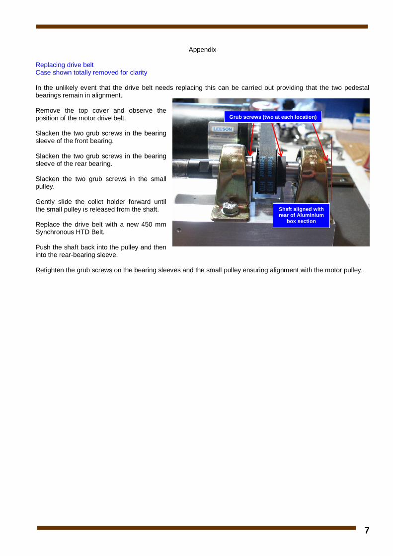
Replacing drive belt Case shown totally removed for clarity In the unlikely event that the drive belt needs replacing this can be carried out providing that the two pedestal bearings remain in alignment. Remove the top cover and observe the position of the motor drive belt. Slacken the two grub screws in the bearing sleeve of the front bearing. Slacken the two grub screws in the bearing sleeve of the rear bearing. Slacken the two grub screws in the small pulley. Gently slide the collet holder forward until the small pulley is released from the shaft. Replace the drive belt with a new 450 mm Synchronous HTD Belt. Push the shaft back into the pulley and then into the rear-bearing sleeve. Retighten the grub screws on the bearing sleeves and the small pulley ensuring alignment with the motor pulley.
Grub screws (two at each location)
Shaft aligned with rear of Aluminium
box section