
Modelling and Control of an Effort Feedback Actuator in ... · MODELLING AND CONTROL OF AN EFFORT...
7
MODELLING AND CONTROL OF AN EFFORT FEEDBACK ACTUATOR IN HELICOPTER FLIGHT CONTROL USING ENERGETIC MACROSCOPIC REPRESENTATION Mikaël MARTIN* (a) , Julien GOMAND* (b) , François MALBURET* (c) , Pierre-Jean BARRE* (d) (*) LSIS, Arts et Métier ParisTech – Aix en Provence (Fr) (a) [email protected] , (b) [email protected] , (c) [email protected], (d) [email protected] , ABSTRACT In helicopter field, electromechanical devices controllers are usually designed and tuned from global analysis with transfer functions calculations. This leads to control architectures with a reduced number of controllers. Their regulating loops are usually global PID controllers where parameters are directly set up on dedicated test benches. Energetic representation tools such as Energetic Macroscopic Representation (EMR) aim at simplifying systems analysis and control providing model and control structuring method. In this paper, a simplified helicopter flight axis control is modelled with the intention of controlling the helicopter stick force feedback. Performances of both global PID and energetic model based inversion controllers are discussed through simulation results. Keywords: causal inversion, model-based control, EMR 1. INTRODUCTION From the first flight in 1903 of Wright Flyer in Kitty Hawk (US) to the last new technology ones, aircrafts have been equipped with mechanical and hydro- mechanical actuators for flight control. Over time, designers have increased the number of elements of each flight axis control to improve pilots comfort. For example, electrohydraulic actuators controlled by a breakthrough analogical Automatic Pilot Module have been introduced in 1980 on the Dauphin Eurocopter to stand in for overload pilot tasks. From 1983 to 1993, embedded equipments have increased of 50%, from 77 (A310) to 115 (A34) units, in the Airbus industries. Friction effort controls, stability and security improvement systems are at the heart of aeronautical industry and leads to more complex and heavier flight controls. However, mechanical and hydro-mechanical systems are relatively heavy, difficult to adjust and without possibilities of evolution. They also have limited dynamic capabilities compared to electromechanical systems but are able to provide higher forces. Researches are focused on development of new architectures to minimise the number of passive elements. Airbus A320 was the first airliner in 1983 with digital fly-by-wire controls and more recently the Dassault Falcom 7X became the first business jet with fly-by-wire controls. Evolution towards electronic control architectures sometimes leads up to the mechanical decoupling between pilot control interfaces and final controls on aircraft’s steering (Defaÿ, 2010). Pilots generally have mini-sticks and are thus totally disconnected from the force applied on flight controls. Fly-by-wire brings a lot of advantages in term of weight, cost and ease to connect in axis flight controls. Possibilities to improve or create new flight control functions are enlarged thanks to the flexibility and the high dynamic of the electronic controls which have ability to adapt flight parameter controls in real time. In the helicopter context, interest of fly-by-wires is reduced compared to its high advantages for planes: distance from pilot sticks to hydraulic power control is quite small and mass gain profits against costs are consequently reduced. Mechanical links between pilot sticks and hydraulic power control is maintained except on the fly-by-wire NH90 Eurocopter helicopter (Perrimond 2006). Nevertheless, active force feedback is a mean to dynamically limit the flight envelope. High or sharp inclination of paddles may lead to collisions between paddles and anti-torque rotor (case of nose-up) or may block off turbines air intake (case of nose- down). Designers are attempted to develop new active flight architectures with more functions, more flexibilities, more securities and more comfort with less elements. Associated control structures are thus becoming more and more complex with difficulties in setting control parameters avoiding over shoots, oscillations and respecting correct response times. The control of an electromechanical device is usually made separately, locally i.e. independently from other surrounding devices. They are elaborated from global transfer function calculations, using Proportional-Integral-Derivative controllers (PID). Transfer function parameters are estimated from flight structure identifications. PID parameters are consequently directly set up on test benches with typical regulating difficulties. This classical “element by element approach” may be useful for a size limited structure, with specifications on time response, over 68
Transcript of Modelling and Control of an Effort Feedback Actuator in ... · MODELLING AND CONTROL OF AN EFFORT...
MODELLING AND CONTROL OF AN EFFORT FEEDBACK ACTUATOR IN HELICOPTER FLIGHT CONTROL USING ENERGETIC MACROSCOPIC
REPRESENTATION
Mikaël MARTIN*(a), Julien GOMAND*(b), François MALBURET*(c), Pierre-Jean BARRE*(d)
(*) LSIS, Arts et Métier ParisTech – Aix en Provence (Fr)
(a)[email protected], (b)[email protected], (c)[email protected], (d)[email protected],
ABSTRACT In helicopter field, electromechanical devices controllers are usually designed and tuned from global analysis with transfer functions calculations. This leads to control architectures with a reduced number of controllers. Their regulating loops are usually global PID controllers where parameters are directly set up on dedicated test benches. Energetic representation tools such as Energetic Macroscopic Representation (EMR) aim at simplifying systems analysis and control providing model and control structuring method. In this paper, a simplified helicopter flight axis control is modelled with the intention of controlling the helicopter stick force feedback. Performances of both global PID and energetic model based inversion controllers are discussed through simulation results. Keywords: causal inversion, model-based control, EMR
1. INTRODUCTION From the first flight in 1903 of Wright Flyer in Kitty Hawk (US) to the last new technology ones, aircrafts have been equipped with mechanical and hydro-mechanical actuators for flight control. Over time, designers have increased the number of elements of each flight axis control to improve pilots comfort. For example, electrohydraulic actuators controlled by a breakthrough analogical Automatic Pilot Module have been introduced in 1980 on the Dauphin Eurocopter to stand in for overload pilot tasks. From 1983 to 1993, embedded equipments have increased of 50%, from 77 (A310) to 115 (A34) units, in the Airbus industries. Friction effort controls, stability and security improvement systems are at the heart of aeronautical industry and leads to more complex and heavier flight controls. However, mechanical and hydro-mechanical systems are relatively heavy, difficult to adjust and without possibilities of evolution. They also have limited dynamic capabilities compared to electromechanical systems but are able to provide higher forces. Researches are focused on development of new architectures to minimise the number of passive elements. Airbus A320 was the first airliner in 1983 with digital fly-by-wire controls and more recently the
Dassault Falcom 7X became the first business jet with fly-by-wire controls. Evolution towards electronic control architectures sometimes leads up to the mechanical decoupling between pilot control interfaces and final controls on aircraft’s steering (Defaÿ, 2010). Pilots generally have mini-sticks and are thus totally disconnected from the force applied on flight controls. Fly-by-wire brings a lot of advantages in term of weight, cost and ease to connect in axis flight controls. Possibilities to improve or create new flight control functions are enlarged thanks to the flexibility and the high dynamic of the electronic controls which have ability to adapt flight parameter controls in real time. In the helicopter context, interest of fly-by-wires is reduced compared to its high advantages for planes: distance from pilot sticks to hydraulic power control is quite small and mass gain profits against costs are consequently reduced. Mechanical links between pilot sticks and hydraulic power control is maintained except on the fly-by-wire NH90 Eurocopter helicopter (Perrimond 2006). Nevertheless, active force feedback is a mean to dynamically limit the flight envelope. High or sharp inclination of paddles may lead to collisions between paddles and anti-torque rotor (case of nose-up) or may block off turbines air intake (case of nose-down).
Designers are attempted to develop new active flight architectures with more functions, more flexibilities, more securities and more comfort with less elements. Associated control structures are thus becoming more and more complex with difficulties in setting control parameters avoiding over shoots, oscillations and respecting correct response times.
The control of an electromechanical device is usually made separately, locally i.e. independently from other surrounding devices. They are elaborated from global transfer function calculations, using Proportional-Integral-Derivative controllers (PID). Transfer function parameters are estimated from flight structure identifications. PID parameters are consequently directly set up on test benches with typical regulating difficulties. This classical “element by element approach” may be useful for a size limited structure, with specifications on time response, over
68
shoot and stmargins. Howactuator is suGraphical appand controllinorder to detersystem and cand more spproperly modnatural causalMacroscopic deducing a glsystem repres
The purpcontrol strateMacroscopic control is deproposed. A determined tolast part, a siminterest of thaPID structure
2. MODEL
This section model of a helumped paramEMR formalexposed in th
2.1. Hel
Initially, a herotor blades aany assistancand consequhydraulic poprovide the (depending opower-actuatocontrol the bmechanical ccontrol inputsfor the pilot. For the sakepassive and aby-step, such
- A dathe f
- A stmoti
- A selem
- An eAuto
- ...
tability by cwever difficulturrounded by proaches can ng multi-physrmine a contro
correctly set cpecifically endel the systemlity. One of th
Representatlobal and a sysentation. pose of this pegy of the s
Representatiscribed and tsystematic m
o control the mulation usinat energetic ap.
LING
is dedicated elicopter fligh
meters model lism to facie next section
licopter axis celicopter piloangle via direcce. With the uently the inowered assist
control effoon the helicopors are locat
blades angle. hains from sts are then one
e of comfortactive devicesas (figure 1):
amper to reducflight control atabilisation acion of the contspring based
ment; electromechano Pilot Module
customising gties come up several physibe used to he
sic systems (Hol architectur
controller paranergetic methm by respectinhese methods tion (EMR) ystematic con
paper is to elasystem usingion tool. A the model usimodel based
stick force fg Matlab/Simpproach comp
to the preseht axis controis then repres
ilitate the mn.
control t directly hadct mechanicalincrease of th
ncrease of thtance becameorts up to 3pter range). Ted under theThe residual tick to the hye of the most
t and/or secus have been i
ce the dynamiaxes; ctuator to protrol axis;
d artificial f
nical actuator e (APM);
gain and phawhen the actiical subsystemelp in modelli
Hautier 2005). e adapted to tameters, graphhods suggest ng physical ais the Energewhich allo
ntrol architectu
aborate a globg the Energe
helicopter axing the EMRcontrol is th
feedback. In tmulink shows tpared to a sing
entation and tol. The propossented using t
model inversi
d to control tl chains, withohe aircraft siheir mass, te necessary 30kN per axThree hydraue rotor plate
frictions of tydraulic actua
important loa
urity, additionintroduced ste
ic capabilities
ovide oscillati
force feedba
controlled by
ase ive ms. ing In
the hic to
and etic ws ure
bal etic xis
R is hen the the gle
the sed the ion
the out ze, the to
xis ulic
to the
ator ads
nal ep-
of
ing
ack
an
Ncosu
imbaacobanstainthfliththan
Fico
Athsto
axreofasmcath(foeathpa
comdo
owadays, heliomplex systeubsystems.
The purpmprovement oased artificial ctive force febjectives arend to give to tates. Force fe
ndication of thhe pilot to oveight controls (
he interface behe stick, the pngle and thus t
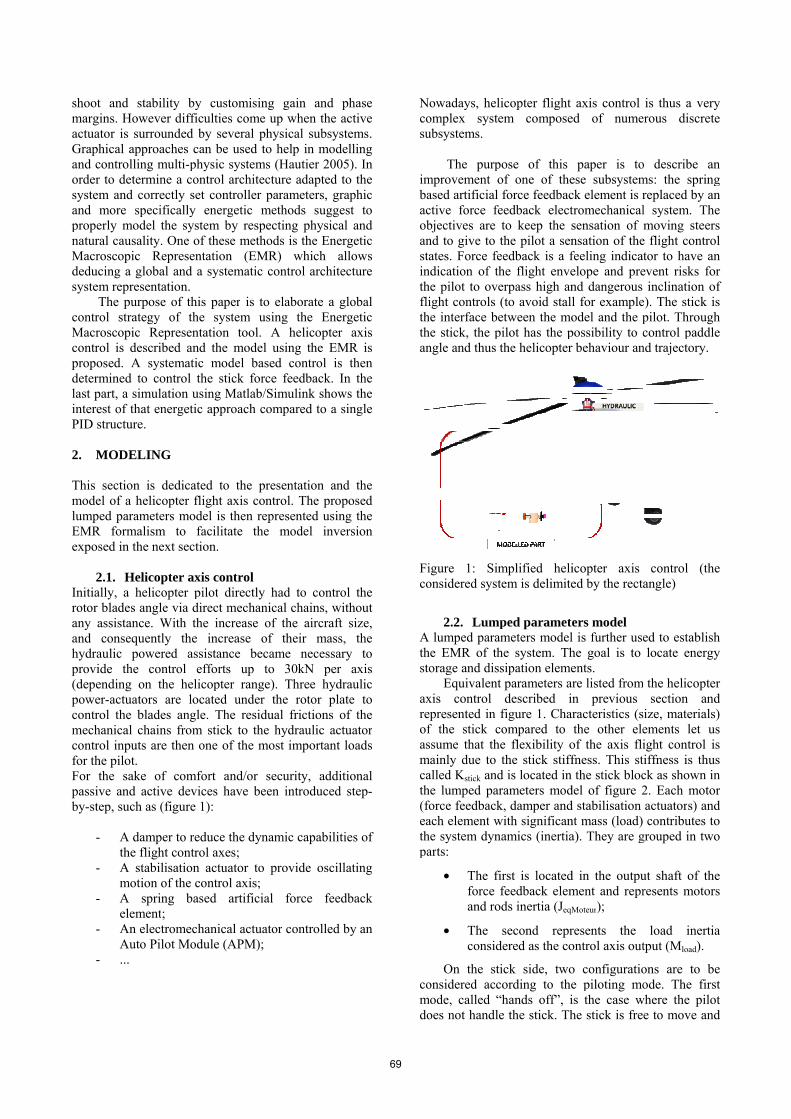
igure 1: Simonsidered syst
2.2. Lump lumped param
he EMR of thorage and diss
Equivalentxis control epresented in ff the stick cssume that the
mainly due to alled Kstick andhe lumped parforce feedbackach element whe system dynarts:
• The fiforce fand ro
• Theconsid
On the stionsidered acc
mode, called “oes not handle
icopter flight em compose
pose of this of one of theforce feedbac
eedback electto keep the sthe pilot a seneedback is a fhe flight enveerpass high an(to avoid stalletween the mopilot has the pthe helicopter
mplified helitem is delimite
ped parametmeters model
he system. Thsipation elemet parameters a
described ifigure 1. Cha
compared to e flexibility othe stick stiff
d is located in rameters modk, damper andwith significannamics (inertia
irst is locatedfeedback elemds inertia (JeqM
second reprdered as the co
ick side, twocording to the“hands off”, ie the stick. Th
axis control ed of nume
paper is toese subsystemck element is rtromechanicalsensation of mnsation of thefeeling indicatelope and prend dangerous l for exampleodel and the p
possibility to cr behaviour an
icopter axis ed by the recta
ers model l is further usehe goal is to ents.
are listed fromn previous
aracteristics (sthe other ele
of the axis flifness. This stthe stick bloc
del of figure 2d stabilisation nt mass (load) a). They are g
d in the outpument and reprMoteur);
resents the ontrol axis out
o configuratioe piloting mois the case whe stick is fre
is thus a veryerous discrete
o describe anms: the springreplaced by anl system. Themoving steer
e flight controtor to have anevent risks fo
inclination oe). The stick ipilot. Throughcontrol paddle
nd trajectory.
control (theangle)
ed to establishlocate energy
m the helicoptesection and
ize, materialsements let uight control iiffness is thuck as shown in2. Each motoactuators) andcontributes to
grouped in two
ut shaft of theresents motor
load inertiatput (Mload).
ons are to beode. The firs
where the piloe to move and
y e
n g n e s
ol n
or of s h e
e
h y
er d s) s s s n
or d o o
e rs
a
e st ot d
69
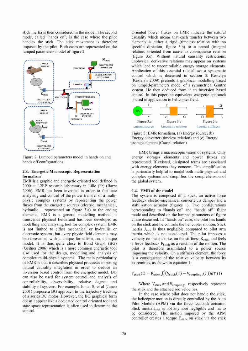
stick inertia is then considered in the model. The second mode, called “hands on”, is the case where the pilot handles the stick. The stick movement is therefore imposed by the pilot. Both cases are represented on the lumped parameters model of figure 2.
Figure 2: Lumped parameters model in hands on and hands off configurations.
2.3. Energetic Macroscopic Representation formalism EMR is a graphic and energetic oriented tool defined in 2000 at L2EP research laboratory in Lille (Fr) (Barre 2006). EMR has been invented in order to facilitate analysing and control of the power transfer of a multi-physic complex systems by representing the power fluxes from the energetic sources (electric, mechanical, hydraulic… represented on figure 3.a) to the ending elements. EMR is a general modelling method: it transcends physical fields and has been developed as modelling and analysing tool for complex system. EMR is not limited to either mechanical or hydraulic or electronic systems but every physic field elements may be represented with a unique formalism, on a unique model. It is thus quite close to Bond Graph (BG) (Geitner 2006) which is a more common energetic tool also used for the design, modelling and analysis of complex multi-physic systems. The main particularity of EMR is that it describes physical processes imposing natural causality integration in order to deduce an inversion based control from the energetic model. BG can also be used for system control and analysis of controllability, observability, relative degree and stability of systems. For example Junco S. et al (Junco 2001) propose a BG approach to the trajectory tracking of a series DC motor. However, the BG graphical form doesn’t appear like a dedicated control oriented tool and state space representation is often used to determine the control.
Oriented power fluxes on EMR indicate the natural causality which means that each transfer between two elements is either a rigid (timeless relation with no specific direction, figure 3.b) or a causal (integral relation, oriented from cause to consequence relation (figure 3.c). Without natural causality restrictions, unphysical derivative relations may appear on systems which lead to uncontrollable energy storage elements. Application of this essential rule allows a systematic control which is discussed in section 3. Kestelyn (Kestelyn 2009) presents a graphical modelling based on lumped-parameters model of a symmetrical Gantry system. He then deduced from it an inversion based control. In this paper, an equivalent energetic approach is used in application to helicopter field.
Figure 3: EMR formalism, (a) Energy source, (b) Energy converter (timeless relation) and (c) Energy storage element (Causal relation) EMR brings a macroscopic vision of systems. Only energy storages elements and power fluxes are represented. If existed, dissipated terms are associated with energy elements they concern. This simplification is particularly helpful to model both multi-physical and complex systems and simplifies the comprehension of the global system.
2.4. EMR of the model The system is composed of a stick, an active force feedback electro-mechanical converter, a damper and a stabilisation actuator (figures 1). Two configurations corresponding to “hands on” and “hands off” flight mode and described on the lumped parameters of figure 2, are discussed. In “hands on” case, the pilot has hands on the stick and he controls the helicopter motion. Stick inertia Jstick is thus negligible compared to pilot arm inertia which is not considered. The pilot imposes a velocity on the stick, i.e. on the stiffness Kstick, and feels a force feedback F as a reaction of the motion. The pilot is therefore assimilated to a power source imposing the velocity. On a stiffness element, the force is a consequence of the relative velocity between its extremities, as shown in equation 1:
F (t) = K ∫ V (T) − V (𝑇) 𝑑𝑇 (1) Where V and V respectively represent
the stick and the attached rod velocities. In the case where pilot does not handle the stick,
the helicopter motion is directly controlled by the Auto Pilot Module (APM) via the force feedback actuator. Stick inertia Jstick is not anymore negligible and has to be considered. The motion imposed by the APM controller creates a torque Γ on stick via the stick
Kstick
EQUIVALENT STIFFNESS
FORCE FEEDBACK
DAMPER
NGEAR BOX
JeqMotor
EQUIVALENTINERTIA
STABILISATION ACTUATOR
Mload
EQUIVALENT LOAD MASS
FRICTIONS
STICK hands on
Kstick
EQUIVALENT STIFFNESS
STICK hands off
STICK STIFFNESS
Jstick
FRICTIONS
ES
Figure 3.acurrent source
e
i
Figure 3.cInertia, stiffness
Figure 3.bkinematic relation
Ω
2Ω
1F
V Ω
70
stiffness Kstick (equation 2). This torque (cause) implies the stick movement Ω (effect).
Γ (t) = 𝐿 ∗ F (𝑡)Ω (t) = ∫ Γ (𝑇)𝑑𝑇 (2)
The active force feedback control consists in
controlling motor torque depending on the position of the flight controls. In our simple representation, electric components are assimilated to an electric energy source which delivers a current i (figure 3a). As shown on the lumped parameters on figure 2, gear box is supposed to be perfect, without clearances. Motor and part of the equivalent axis flight control inertia are merged and designated by JeqMotor (figure 4). According to equation 2, inertia imposes angular velocity; velocity which is carried towards the first coupling on figure 4. From that coupling, velocity is propagated and modulated by the axis kinematic to the next energy potential storage elements. Damper effect is added in coupling 2. It is a passive element assimilated to a mechanic energy source (figure 4). Its role is to limit the flight dynamic control by outputting a resistant torque opposed and proportional to the stick velocity, like a viscous force. The last part of the modelled system is constituted of the stabilisation system. Depending on helicopter measurement and reference attitude, APM calculates and transmits electric orders towards stabilisation actuator. Motors are generally mechanically fixed on non-moving structures. In this paper, the motor is placed in series inside the flight control. Electromotive force (emf) is then deduced from the velocities subtraction, one imposed by the upper part (Vload), the other one from the underneath system (Vcoupling2). Mathematic relation is explained in equation 3, where KΦ is the electromechanical coefficient of the stabilisation motor. e (t) = K ∗ V (t) − V (𝑡) (3) The remaining part of the axis helicopter flight control is mainly composed of the hydraulic load assistance. Load is assimilated to an equivalent mass
Mload and is represented by a mechanical effort source (figure 4). Displacement of that equivalent load is representative of paddles displacement. The time constant of the motor electrical part is supposed to be negligible compared to the mechanical time constants. The electrical part of the active force feedback actuator is therefore not represented. 3. CONTROL This section focuses on the determination of the control architecture in order to control the stick force feedback. The energetic model described in previous section allows a systematic model based inversion control. 3.1. Model based inversion control Control architectures of multi-element systems are often separately elaborated and locally tuned. Their regulating loops are usually PID controllers where gain parameters are directly set up on dedicated bench tests. Difficulties in tuning correctors then appear when the system contains several energetic interactions, in case of complex multi-elements system for example. Defining control architecture of a system is determining the exact inverse of the model (Barre 2006). As the EMR model has been represented with rigid and causal relations, two different model based inversion control solutions are described in this section. 3.1.1. Direct inversion The inversion of a bijective rigid conversion is obtained by directly inverse the relation which results in determining regulating value according to a desired value like exposed in equation (4): a torque 𝜞stick is applied to the stick of length Lstick which generates a force Fstick. The inversion of the model consists in calculating a regulating torque 𝜞stick_REG to obtain the desired stick force Fstick_DES. Rigid inversion using EMR formalism is exposed in figure 5.
F = ⎯⎯⎯⎯⎯ Γ = 𝐿 ∗ F (4) 3.1.2. Indirect inversion The inversion of a causal relation consists in determining the input of a storage element depending on
71
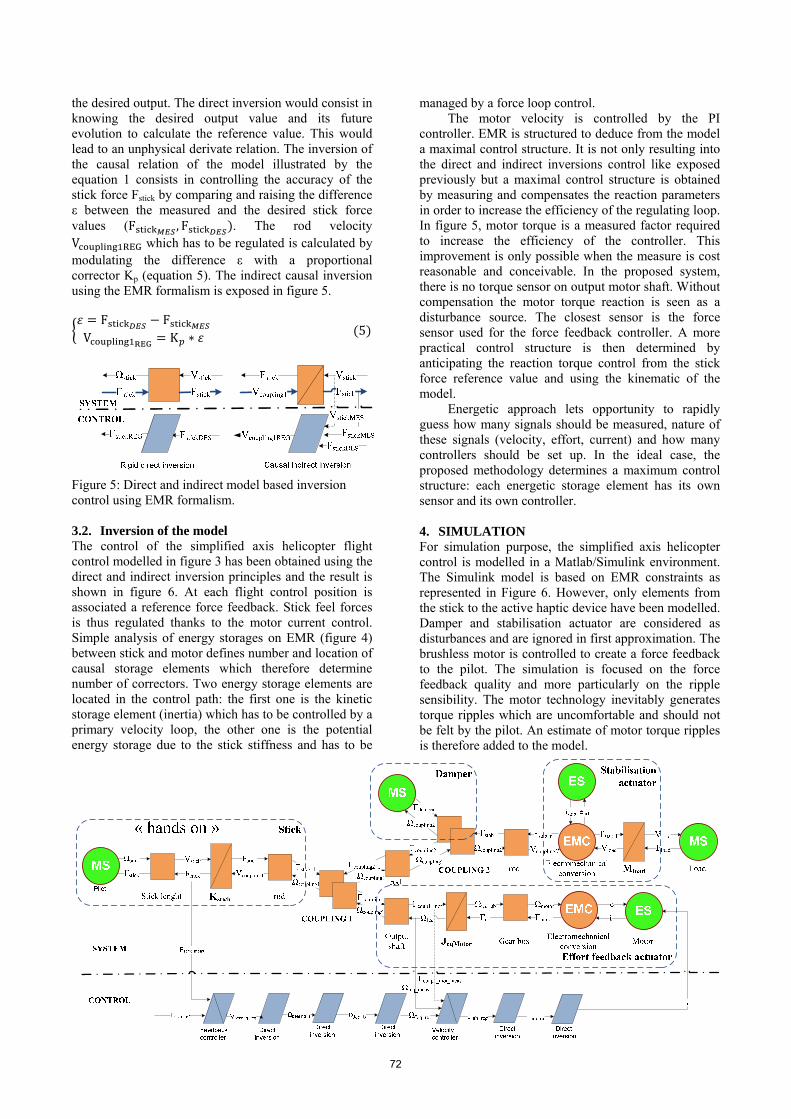
the desired output. The direct inversion would consist in knowing the desired output value and its future evolution to calculate the reference value. This would lead to an unphysical derivate relation. The inversion of the causal relation of the model illustrated by the equation 1 consists in controlling the accuracy of the stick force Fstick by comparing and raising the difference ε between the measured and the desired stick force values (F , F ). The rod velocity V which has to be regulated is calculated by modulating the difference ε with a proportional corrector Kp (equation 5). The indirect causal inversion using the EMR formalism is exposed in figure 5. 𝜀 = F − FV = K ∗ 𝜀 (5)
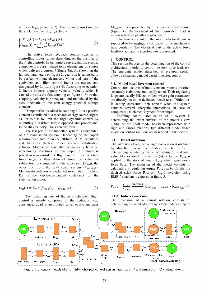
Figure 5: Direct and indirect model based inversion control using EMR formalism. 3.2. Inversion of the model The control of the simplified axis helicopter flight control modelled in figure 3 has been obtained using the direct and indirect inversion principles and the result is shown in figure 6. At each flight control position is associated a reference force feedback. Stick feel forces is thus regulated thanks to the motor current control. Simple analysis of energy storages on EMR (figure 4) between stick and motor defines number and location of causal storage elements which therefore determine number of correctors. Two energy storage elements are located in the control path: the first one is the kinetic storage element (inertia) which has to be controlled by a primary velocity loop, the other one is the potential energy storage due to the stick stiffness and has to be
managed by a force loop control. The motor velocity is controlled by the PI
controller. EMR is structured to deduce from the model a maximal control structure. It is not only resulting into the direct and indirect inversions control like exposed previously but a maximal control structure is obtained by measuring and compensates the reaction parameters in order to increase the efficiency of the regulating loop. In figure 5, motor torque is a measured factor required to increase the efficiency of the controller. This improvement is only possible when the measure is cost reasonable and conceivable. In the proposed system, there is no torque sensor on output motor shaft. Without compensation the motor torque reaction is seen as a disturbance source. The closest sensor is the force sensor used for the force feedback controller. A more practical control structure is then determined by anticipating the reaction torque control from the stick force reference value and using the kinematic of the model. Energetic approach lets opportunity to rapidly guess how many signals should be measured, nature of these signals (velocity, effort, current) and how many controllers should be set up. In the ideal case, the proposed methodology determines a maximum control structure: each energetic storage element has its own sensor and its own controller. 4. SIMULATION For simulation purpose, the simplified axis helicopter control is modelled in a Matlab/Simulink environment. The Simulink model is based on EMR constraints as represented in Figure 6. However, only elements from the stick to the active haptic device have been modelled. Damper and stabilisation actuator are considered as disturbances and are ignored in first approximation. The brushless motor is controlled to create a force feedback to the pilot. The simulation is focused on the force feedback quality and more particularly on the ripple sensibility. The motor technology inevitably generates torque ripples which are uncomfortable and should not be felt by the pilot. An estimate of motor torque ripples is therefore added to the model.
72
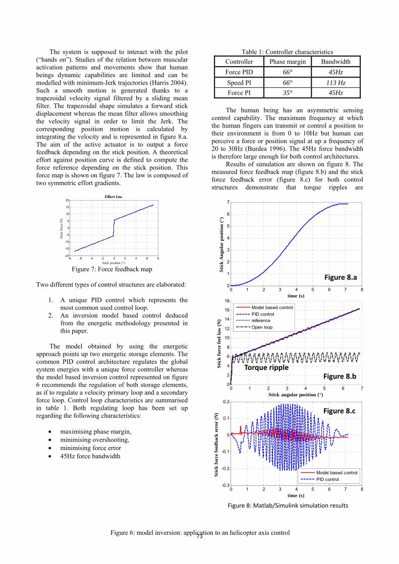
The system is supposed to interact with the pilot (“hands on”). Studies of the relation between muscular activation patterns and movements show that human beings dynamic capabilities are limited and can be modelled with minimum-Jerk trajectories (Harris 2004). Such a smooth motion is generated thanks to a trapezoidal velocity signal filtered by a sliding mean filter. The trapezoidal shape simulates a forward stick displacement whereas the mean filter allows smoothing the velocity signal in order to limit the Jerk. The corresponding position motion is calculated by integrating the velocity and is represented in figure 8.a. The aim of the active actuator is to output a force feedback depending on the stick position. A theoretical effort against position curve is defined to compute the force reference depending on the stick position. This force map is shown on figure 7. The law is composed of two symmetric effort gradients.
Figure 7: Force feedback map
Two different types of control structures are elaborated:
1. A unique PID control which represents the
most common used control loop. 2. An inversion model based control deduced
from the energetic methodology presented in this paper.
The model obtained by using the energetic
approach points up two energetic storage elements. The common PID control architecture regulates the global system energies with a unique force controller whereas the model based inversion control represented on figure 6 recommends the regulation of both storage elements, as if to regulate a velocity primary loop and a secondary force loop. Control loop characteristics are summarised in table 1. Both regulating loop has been set up regarding the following characteristics:
• maximising phase margin, • minimising overshooting, • minimising force error • 45Hz force bandwidth
Table 1: Controller characteristics Controller Phase margin Bandwidth Force PID 66° 45Hz Speed PI 66° 113 Hz Force PI 35° 45Hz
The human being has an asymmetric sensing
control capability. The maximum frequency at which the human fingers can transmit or control a position to their environment is from 0 to 10Hz but human can perceive a force or position signal at up a frequency of 20 to 30Hz (Burdea 1996). The 45Hz force bandwidth is therefore large enough for both control architectures. Results of simulation are shown on figure 8. The measured force feedback map (figure 8.b) and the stick force feedback error (figure 8.c) for both control structures demonstrate that torque ripples are
-8 -6 -4 -2 0 2 4 6 8-20
-15
-10
-5
0
5
10
15
20Effort law
Stic
k fo
rce
(N)
Stick position (°)
Figure 6: model inversion: application to an helicopter axis control
0 1 2 3 4 5 6 7 80
1
2
3
4
5
6
7
Stic
k A
ngul
ar p
ositi
on (°
)
time (s)
0 1 2 3 4 5 6 7 8-0.3
-0.2
-0.1
0
0.1
0.2
Stic
k fo
rce
feed
back
err
or (N
)
time (s)
Model based controlPID control
0 1 2 3 4 5 6 70
2
4
6
8
10
12
14
16
18
Stic
k fo
rce
feel
law
(N)
Stick angular position (°)
Model based controlPID controlreferenceOpen loop
Torque ripple
Figure 8.a
Figure 8.b
Figure 8.c
Figure 8: Matlab/Simulink simulation results
73
significantly reduced thanks to the regulations. Nevertheless, better performances on force feedback error are observed for the model based control with a maximum force error of 100mN peak to peak. The maximum force error on PID control reaches 400mN peak to peak which is largely felt by the human sensibility. 5. CONCLUSION Energetic tools such as EMR recently became visible to structure models and determine a systematic model based control. An axis helicopter flight control has been modelled and an active force feedback has been generated on stick. The EMR energetic method has been used to define the control architecture respecting natural causality and resulting performances are compared to a more common used PID control loop. A Matlab/Simulink simulation demonstrates that the model based control allows the smoothing of the motor torque ripples whereas the PID controller only reduces the amplitude of the torque ripple. The pilot comfort is therefore improved. ACKNOWLEDGMENTS This work has been supported by Olivier Honnorat, innovation project manager at Eurocopter, Marignane (Fr).
REFERENCES Barre, P.J., Bouscayrol, A., Delarue, P., Dumetz, E.,
Giraud, F., Hautier, J.P., 2006. Inversion-based control of electromechanical systems using causal graphical descriptions. IEEE-IECON'06 - 32nd Annual Conference on Industrial Electronics, (pp. 5276-5281).
Burdea, G.C., 1996, Force and touch feedback for virtual reality, John Wiley and Sons, ISBN 0-471-02141-5
Defaÿ, F., Alazard, D., Dehais, F., 2010. Impedance active control of flight control devices. ISAE, Toulouse University.
Geitner, H.G., 2006, Power flow diagrams using a bond graph library under Simulink, IEEE-IECON’06 - 32nd Annual Conference on Industrial Electronics, pp. 5282-5288.
Harris, C.M., 2004, Exploring smoothness and discontinuities in human motor behavior with Fourier analysis, Mathematical biosciences, vol. 188, pp. 99-116.
Hautier, J.P. Barre, P.J., 2005, The causal ordering graph - A tool for system modelling and control law synthesis, Journal of studies in informatics and control, vol. 13, no. 4, pp. 265-283.
Junco, S., Donaire, A., Garnero, G., 2001, Trajectory Tracking on Bond Graphs. Procedures and applications to DC electrical drives, ESS01, 13th European Simulation Symposium, Simulation in Industry, , October 18-20, Marseilles, France, SCS Europe Bvba, pp. 799-805.
Kestelyn, X., Gomand, J., Bouscayrol, A., & Barre, P.J., 2009, Control of a symmetrical dual Gantry system using Energetic Macroscopic Representation, Solid State Phenomena, vol. 144, pp 181-185.
Perrimond, G., Belan, G., 2006. NH90, A successful programme, TTU international, 24 May, Supplement to n°162.
74


![Molecular Modelling of Switchable [2]Rotaxanes](https://static.fdocuments.es/doc/165x107/585cca9a1a28abed21907353/molecular-modelling-of-switchable-2rotaxanes.jpg)