Ponencias / Reports - blain.de · muy a menudo en edificios bajos y de media altura (de entre 2 y 5...
8
Ponencias / Reports 83 DISEÑO DE UNIDAD DE PRUEBA PARA VÁLVULAS DE ASCENSORES HIDRÁULICOS Dr. K. Ferhat Çelik1, Ersan Barlas y Dr. C. Erdem Imrak3 1 Blain Hydraulics GmbH, Alemania 2 Barlas Consultancy, Turquía 3 Facultad de Ingeniería Mecánica, Universidad Técnica de Estambul, Turquía Palabras clave: Ascensor hidráulico, grupo de válvulas, unidad de prueba ABSTRACT Los ascensores hidráulicos son apropiados para ascen- sores de pasajeros de corto recorrido y para montacar- gas, y tienen ventajas intrínsecas tales como unos cos- tes de mantenimiento reducidos, un diseño flexible, medidas superiores de seguridad, instalación más senci- lla y económica, etc. Los principales componentes de una unidad hidráulica son un depósito de aceite, bomba, motor, y válvula de control de flujo. La válvula controla el flujo del aceite hacia el gato (en viajes ascendentes) o hacia el depósito (en viajes des- cendentes) mediante la redirección hacia el depósito o la restricción de la sección transversal del flujo según la velocidad que se le quiera dar al ascensor. La conforta- bilidad del trayecto depende del diseño específico de la válvula de control. Para observar el comportamiento mecánico de varias válvulas se ha diseñado una unidad de prueba. En este estudio se presentan y analizan en detalle la estructura general y los componentes de la uni- dad de prueba para ascensores hidráulicos. 1. INTRODUCCIÓN Un ascensor hidráulico es un elevador que funciona mediante el peso o la presión sobre aceite hidráulico. Los ascensores hidráulicos convencionales se utilizan muy a menudo en edificios bajos y de media altura (de entre 2 y 5 plantas). Utilizan un émbolo hidráulico para empujar el ascensor hacia arriba; en algunos casos, el pistón hidráulico (émbolo) está formado por tubos con- céntricos telescópicos, que permiten que un tubo de no mucha profundidad contenga el mecanismo bajo el piso inferior. En otros casos, el pistón necesita un hueco más profundo bajo el piso más bajo, generalmente con pro- tección de PVC (Inglis, 1995 ; Imrak & Gerdemeli, 2000). La principal ventaja de los sistemas hidráulicos es que pueden multiplicar con facilidad la potencia relativamen- te débil de la bomba y generar la fuerza necesaria para elevar la cabina del ascensor. Se integra fácilmente en la mayoría de los diseños arquitectónicos y tiene una larga vida útil con mantenimiento mínimo, comodidad de viaje, y un funcionamiento totalmente seguro. Es ventajoso en cuanto a costes y su instalación es sencilla. (Strakosch, 1998 ; Scheffer et al, 1998). Se diseñan con factores de seguridad para posibles excesos de carga. TEST UNIT DESIGN FOR HYDRAULIC ELEVATOR VALVES Dr. K. Ferhat Çelik1, Ersan Barlas2 and Dr. C. Erdem Imrak3 1Blain Hydraulics GmbH, Germany 2Barlas Consultancy, Turkey 3Faculty of Mechanical Engineering, Istanbul Technical University, Turkey Key Words: Hydraulic elevator, valve block, test unit ABSTRACT Hydraulic elevators are suitable for low-rise passenger and goods elevators and have their inherent advantages, such as low maintenance cost, flexibility of design, supe- rior safety measures, easy and cost effective installations, etc. The main components of a hydraulic power unit are oil reservoir, pump, motor, and flow control valve. The valve controls the oil flow to the jack (up travel) or to the tank (down travel) by either diverting some oil back into the tank or restricting the flow cross-section depen- ding on the intended elevator speed. Comfort of the travel depends on the particular design of the control valve. In order to observe the mechanical behaviour of various val- ves, a test unit is designed. In this study, the general structure and components of the test unit for hydraulic elevators are introduced and explained in detail. 1. INTRODUCTION A hydraulic elevator is a lift operated by the weight or pressure of hydraulic oil. Conventional hydraulic eleva- tors are quite common for low and medium rise buildings (2-5 stories). They use a hydraulically powered plunger to push the elevator upwards. On some, the hydraulic piston (plunger) consists of telescoping concentric tubes, allo- wing a shallow tube to contain the mechanism below the lowest floor. On others, the piston requires a deeper hole below the bottom landing, usually with a PVC casing for protection (Inglis, 1995 ; Imrak & Gerdemeli, 2000). The main advantage of hydraulic systems is they can easily multiply the relatively weak force of the pump to generate the stronger force needed to lift the elevator car. It integrates easily with most architectural designs and has long operational life with minimal maintenance, ride comfort and totally safe operation. It is cost- effective and has easy installation features. (Strakosch, 1998 ; Scheffer et al, 1998). They are desig- ned with safety factors for excess load conditions. For smaller and medium sized installations the cantileve- red sling in combination with a telescopic cylinder offers the best elevator application (Tagliabau, 1996). Hydraulic elevator systems lift a car using a hydraulic ram, a fluid-driven piston mounted inside a cylinder. The cylinder is connected to a fluid-pumping system (typically, hydraulic systems like this use mineral oil, but other forma6vr36.qxd 19/02/2007 12:11 PÆgina 1
Transcript of Ponencias / Reports - blain.de · muy a menudo en edificios bajos y de media altura (de entre 2 y 5...

Ponencias / Reports
83
DISEÑO DE UNIDAD DE PRUEBA PARA VÁLVULAS DE
ASCENSORES HIDRÁULICOS
Dr. K. Ferhat Çelik1, Ersan Barlas y Dr. C. Erdem Imrak3
1 Blain Hydraulics GmbH, Alemania2 Barlas Consultancy, Turquía
3 Facultad de Ingeniería Mecánica, UniversidadTécnica de Estambul, Turquía
Palabras clave: Ascensor hidráulico, grupo de válvulas, unidad de prueba
ABSTRACTLos ascensores hidráulicos son apropiados para ascen-sores de pasajeros de corto recorrido y para montacar-gas, y tienen ventajas intrínsecas tales como unos cos-tes de mantenimiento reducidos, un diseño flexible,medidas superiores de seguridad, instalación más senci-lla y económica, etc. Los principales componentes deuna unidad hidráulica son un depósito de aceite, bomba,motor, y válvula de control de flujo.La válvula controla el flujo del aceite hacia el gato (enviajes ascendentes) o hacia el depósito (en viajes des-cendentes) mediante la redirección hacia el depósito o larestricción de la sección transversal del flujo según lavelocidad que se le quiera dar al ascensor. La conforta-bilidad del trayecto depende del diseño específico de laválvula de control. Para observar el comportamientomecánico de varias válvulas se ha diseñado una unidadde prueba. En este estudio se presentan y analizan endetalle la estructura general y los componentes de la uni-dad de prueba para ascensores hidráulicos.
1. INTRODUCCIÓNUn ascensor hidráulico es un elevador que funcionamediante el peso o la presión sobre aceite hidráulico.Los ascensores hidráulicos convencionales se utilizanmuy a menudo en edificios bajos y de media altura (deentre 2 y 5 plantas). Utilizan un émbolo hidráulico paraempujar el ascensor hacia arriba; en algunos casos, elpistón hidráulico (émbolo) está formado por tubos con-céntricos telescópicos, que permiten que un tubo de nomucha profundidad contenga el mecanismo bajo el pisoinferior. En otros casos, el pistón necesita un hueco másprofundo bajo el piso más bajo, generalmente con pro-tección de PVC (Inglis, 1995 ; Imrak & Gerdemeli, 2000).La principal ventaja de los sistemas hidráulicos es quepueden multiplicar con facilidad la potencia relativamen-te débil de la bomba y generar la fuerza necesaria paraelevar la cabina del ascensor. Se integra fácilmente en lamayoría de los diseños arquitectónicos y tiene una largavida útil con mantenimiento mínimo, comodidad de viaje,y un funcionamiento totalmente seguro. Es ventajoso encuanto a costes y su instalación es sencilla. (Strakosch,1998 ; Scheffer et al, 1998). Se diseñan con factores deseguridad para posibles excesos de carga.
TEST UNIT DESIGN FOR HYDRAULIC
ELEVATOR VALVES
Dr. K. Ferhat Çelik1, Ersan Barlas2 and Dr. C. Erdem Imrak3
1Blain Hydraulics GmbH, Germany2Barlas Consultancy, Turkey
3Faculty of Mechanical Engineering, IstanbulTechnical University, Turkey
Key Words: Hydraulic elevator, valve block, test unit
ABSTRACTHydraulic elevators are suitable for low-rise passengerand goods elevators and have their inherent advantages,such as low maintenance cost, flexibility of design, supe-rior safety measures, easy and cost effective installations,etc. The main components of a hydraulic power unit areoil reservoir, pump, motor, and flow control valve. The valve controls the oil flow to the jack (up travel) or tothe tank (down travel) by either diverting some oil backinto the tank or restricting the flow cross-section depen-ding on the intended elevator speed. Comfort of the traveldepends on the particular design of the control valve. Inorder to observe the mechanical behaviour of various val-ves, a test unit is designed. In this study, the generalstructure and components of the test unit for hydraulicelevators are introduced and explained in detail.
1. INTRODUCTIONA hydraulic elevator is a lift operated by the weight orpressure of hydraulic oil. Conventional hydraulic eleva-tors are quite common for low and medium rise buildings(2-5 stories). They use a hydraulically powered plunger topush the elevator upwards. On some, the hydraulic piston(plunger) consists of telescoping concentric tubes, allo-wing a shallow tube to contain the mechanism below thelowest floor. On others, the piston requires a deeper holebelow the bottom landing, usually with a PVC casing forprotection (Inglis, 1995 ; Imrak & Gerdemeli, 2000).The main advantage of hydraulic systems is they caneasily multiply the relatively weak force of the pump togenerate the stronger force needed to lift the elevator car.It integrates easily with most architectural designs andhas long operational life with minimal maintenance, ridecomfort and totally safe operation. It is cost- effective andhas easy installation features.(Strakosch, 1998 ; Scheffer et al, 1998). They are desig-ned with safety factors for excess load conditions. For smaller and medium sized installations the cantileve-red sling in combination with a telescopic cylinder offersthe best elevator application (Tagliabau, 1996).Hydraulic elevator systems lift a car using a hydraulicram, a fluid-driven piston mounted inside a cylinder. Thecylinder is connected to a fluid-pumping system (typically,hydraulic systems like this use mineral oil, but other
forma6vr36.qxd 19/02/2007 12:11 PÆgina 1

Ponencias / Reports
incompressible fluids - such asbiodegradable, fire resistantfluids - would also work). Thehydraulic system has threeparts as illustrated in Figure 1(Day, 2000): a tank (the fluidreservoir), a pump, poweredby an electric motor and avalve between the cylinderand the reservoir.
Working principle of EV 100elevator control valve is shown in Figure 2. The pump for-ces fluid from the tank into a pipe leading to the cylinder.When the pump is started, solenoids A and B, which arenormally open, are energized. Initially, a by-pass valve(U) is open therefore, the pressurized fluid will take thepath of least resistance and return to the fluid reservoir(by-passing). But when the by-pass valve (U) starts toclose (due to the pressure increase in the pilot-chamber),the pressurized fluid has nowhere to go except into thecylinder (Hadorn, 1986) by opening a check valve (W).As the fluid collects in the cylinder, it pushes the pistonup, lifting the elevator car. When the car approaches thecorrect floor, the control system deenergizes solenoid Bto decelerate the car from full speed to leveling.
Close to the floor level, the control system also deenergi-zes solenoid A and at the same time, sends a signal tothe electric motor to gradually shut off the pump. With thepump off, there is no more fluid flowing into the cylinder,but the fluid that is already in the cylinder cannot escape(it can't flow backward through the control valve since thecheck valve (W) is closed).The piston rests on the fluid, and the car stays where it is(Matsudo et al, 1996). To lower the car, the elevator con-trol system energizes solenoids C and D, which are nor-mally closed.Pressure in the pilot-chamber of a down-valve (X) drops,resulting in opening of the downvalve (X). When the sole-noids open the down-valve, the fluid that has collected inthe cylinder can flow out into the fluid reservoir. Theweight of the car and the cargo pushes down on the pis-ton, which drives the fluid into the reservoir. The car gra-dually descends. To stop the car at a lower floor, the con-trol system first deenergizes solenoid C for deceleration
Para instalaciones pequeñas y medianas la suspensión envoladizo, en combinación con un cilindro telescópico, ofrecela mejor solución para ascensores (Tagliabau, 1996).Los sistemas de ascensor hidráulico elevan el cochemediante un pistón accionado mediante un fluido monta-do dentro de un cilindro, que está conectado a un sistemade bombeo de fluido (de forma típica, los sistemas hidráu-licos de este tipo usan aceites de origen mineral, perootros fluidos incompresibles, tales como ciertos fluidos bio-degradables o resistentes al fuego, pueden funcionar tam-bién). El sistema hidráulico tiene tres partes, tal y como seilustra en la Figura 1 (Day, 2000): un depósito (la reservade fluido), una bomba, accionada por un motor eléctrico, yuna válvula entre el cilindro y la reserva.
El principio de funcionamiento de la válvula de controlpara ascensores EV 100 se muestra en la Figura 2. Labomba fuerza el fluido desde el depósito hasta un con-ducto que llega al cilindro. Cuando la bomba se activa,se abre una válvula de paso (U) y por tanto el fluido pre-surizado tomará la ruta que presente menor resistencia yvolverá a la reserva de fluidos (dando un rodeo). Perocuando la válvula de paso (U) empieza a cerrarse (debi-do al aumento de presión en la cámara piloto), el fluidopresurizado no tiene sitio a dónde ir sino al cilindro.(Hadorn 1986) mediante la apertura de una válvula decomprobación (W). A la vez que se concentra el fluidoen el cilindro, se empuja el pistón hacia arriba, ele-vando la cabina del ascensor. Cuando la cabina seaproxima al piso correcto, el sistema de control des-energiza el solenoide B para decelerar la cabinadesde la velocidad máxima al posicionado.Cerca del nivel del piso, el sistema de control des-energiza también el solenoide A y al mismo tiempoenvía una señal al motor eléctrico para cerrar deforma gradual la bomba. Con la bomba inactiva, nohay más fluido entrando en el cilindro, pero el fluidoque ya está en el cilindro no puede salir (no puede irhacia atrás a través de la válvula de control ya que laválvula de comprobación (W) está cerrada).Con el pistón en el fluido, la cabina no se mueve(Matsudo et al, 1996). Para bajar la cabina, el sistema decontrol del ascensor activa los solenoides C y D queestán normalmente cerrados.La presión en la cámara piloto de una válvula de bajada(X) desciende, lo que resulta en la abertura de la válvulade bajada (X). Cuando los solenoides abren la válvulade bajada, el fluido que hay en el cilindro puede salirsedel depósito de fluido. El peso de la cabina y la cargapresionan el pistón, que conduce el fluido al depósito. Lacabina desciende gradualmente. Para parar la cabina enel piso inferior, el sistema de control primero desactiva elsolenoide C para la deceleración y más tarde el solenoi-de D al nivel del psio (Saschi, 1992; Von Holzen, 1997).La unidad de bomba del ascensor consiste en un tanqueintegralmente soldado con acabado aislado de cauchopara bomba y motor, silenciador hidráulico y aislamientode caucho entre la base de la unidad de bomba y el piso.Una vez instalados, los ascensores hidráulicos funcionande forma fiable y requieren poco mantenimiento. Varios
84
forma6vr36.qxd 19/02/2007 12:11 PÆgina 2
Ponencias / Reports
and later solenoid D at the floor level (Saschi, 1992 ; VonHolzen, 1997). The pump unit of the elevator consists ofan integrally welded tank with rubber isolated mountingfor the pump and motor, hydraulic muffler and rubber iso-lation between the pump unit base and the floor.Once installed, the hydraulic elevators operate reliablyand are discreetly maintained. Various hydraulic compo-nents used in their construction are designed as per thesafety standards.Hydraulic elevators are rather common. Like all eleva-tors, they must meet certain specifications and regula-tions. They must also be inspected as regulations dictda-tes instead of often to ensure safety (Tagliabau, 1997).Comfort of the travel depends on the particular design ofthe control valve. In order to observe the mechanicalbehaviour of various valves, a test unit is designed. Inthis study, the general structure and components of thetest unit for hydraulic elevators are introduced and explai-ned in detail.
2. INDOOR TEST TOWERTest tower designed by authors can be used for testing,adjusting hydraulic elevator equipments and especiallydeveloping control and rupture valves for hydraulic ele-vators. This indoor test tower is also intended for training
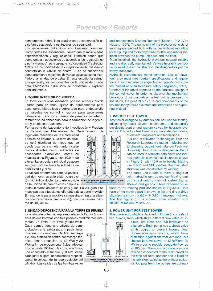
of elevator engineers and technicians. It is part of Elevator Technologies Test andResearch Laboratory situated in MechanicalEngineering Department, Istanbul TechnicalUniversity. Test tower is designed so that itcan be used to simulate both direct and indi-rect hydraulic elevator installations as shownin Figure 3, with 10.9 m in height. Makinguse of NPI and NPU profiles, the main steelstructure was constructed by welding.The pump unit is able to move a single ortwin hydraulic ram by choice. Moving partof the test unit consists of a steel frame,sheave and guides. Three different situa-
tions of the moving part are shown in Figure 4. Restform of the moving part is shown in (a) and direct drivesituation is shown in (b) with 3.96 m maximum stroke.The last figure (c), is indirect drive situation with10.343 m maximum stroke.
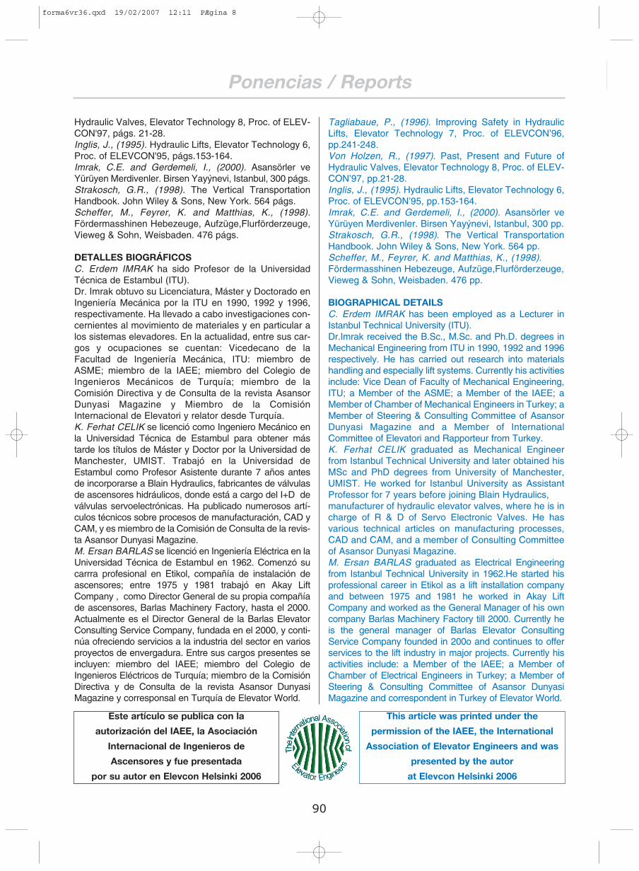
3. POWER UNIT FOR TEST TOWERThe power unit, which is depicted in Figure 5, consists oftwo pumps, from which three different flow rates of 75
lt/min, 125 lt/min and 200 lt/min can beattainable. Each pump has a check valveat its output to prevent inverse flow.Submersible type motors, which haveprotection against thermal overload, arechosen to have power of 12 kW and 20kW in order to provide adequate flow upto 100 bar. There are two collectors oneof which connected to the tank, called asthe tank collector, another one is fixed onthe jack side, called as the cylinder collec-tor. Outputs from the pumps are connec-
componentes hidráulicos usados en su construcción sediseñan de acuerdo a estándares de seguridad.Los ascensores hidráulicos son bastante comunes.Como todos los ascensores, tienen que cumplir ciertasespecificaciones y regulaciones. También tienen quesometerse a inspecciones de acuerdo a las regulacionesy no "a menudo", para asegurar su seguridad (Tagliabau,1997). La comodidad de los viajes depende del diseñoconcreto de la válvula de control. A fin de observar elcomportamiento mecánico de varias válvulas, se ha dise-ñado una unidad de prueba. En este estudio, la estruc-tura general y los componentes de la unidad de pruebapara ascensores hidráulicos se presentan y explicandetalladamente.
2. TORRE INTERIOR DE PRUEBA La torre de prueba diseñada por los autores puedeusarse para pruebas, ajuste de equipamiento paraascensores hidráulicos y sobre todo para el desarrollode válvulas de control y ruptura para ascensoreshidráulicos. Esta torre interior de pruebas de interiortambién se ha concebido para la formación de ingenie-ros y técnicos de ascensor. Forma parte del Laboratorio de Investigación y Pruebasde Tecnologías Elevadoras del Departamento deIngeniería Mecánica de la UniversidadTécnica de Estambul. La torre de prue-ba está diseñada de modo que sepueda usar para simular tanto instala-ciones directas como indirectas deascensores hidráulicos, como semuestra en la Figura 3, con 10,9 m dealtura. La estructura principal de acerose construyó mediante la soldadura deperfiles NPI y NPU.La unidad de bombeo tiene la posibili-dad de mover un solo pistón o un pis-tón hidráulico doble. La parte moviblede la unidad de prueba está compues-ta de un marco de acero, polea y guías. En la Figura 4 semuestran tres situaciones diferentes de la parte movible.El resto de la parte movible se muestra en (a) y la situa-ción de transmisión directa en (b), con una carrera máxi-ma de 10,343 m.
3. UNIDAD DE POTENCIA PARA LA TORRE DE PRUEBALa unidad de potencia, representada en la Figura 5, con-siste de dos bombas con tres posibles rendimientos dife-rentes, 75 l/min, 125 l/min y 200 l/min.Cada bomba tiene una válvula de com-probación a la salida para impedir flujosinversos. Los motores, de tipo sumergi-ble, con protección contra sobrecarga tér-mica, tienen potencias de 12 kWs y 20kWs a fin de proporcionar flujos adecua-dos de hasta 100 bar. Hay dos colectores,uno conectado al tanque, y el otro locali-zado junto al gato, denominados respecti-vamente colector del tanque y colector delcilindro. Las salidas de las bombas están
85
forma6vr36.qxd 19/02/2007 12:11 PÆgina 3

EPSA
ted to the tank collector from where flow is distributed toa valve.There are two EV 100 mechanical valves (3/4” and 1 ½”)on the power unit. Each valve has separate ball valves at
the pump and cylinder ports so thatby closing and opening the neces-sary ball valves one of the two con-trol valves can be easily set in ope-ration. A servo electronic controlvalve (SEV 1 ½”) with its electroniccard is also provided with the testunit, which can be placed on theunit by removing the mechanicalone. An adjustable pressure relivevalve and a manometer, rangedbetween 0 – 160 bar, are providedwith the power unit for protection
and for measuring the pressure in the tank connector. Atank heater with 20° C start-setting and a hand pump arealso included in the power unit. The cylinder-ports of thevalves are connected to the cylinder collector throughhoses and ball valves. Each cylinder has a R10 rupturevalve that joins the cylinder collector via a ball valve. Thecylinder collector includes a by-pass line, which is com-manded manually through a ball valve to lower the ele-vator. A rotational encoder is added to the system tomeasure elevator speed via either a dial gauge or soft-ware that is run by a PC with an interface, called WIN-Tacho.The tank has inside a tray to prevent pieces falling intothe oil while assembling or disassembling the valves. Ithas also a lid which protects the oil and the control valvegroup from unclean environment. On/off switches of the
pumps, as well as the call andthe emergency stop switchesare placed on the tank to easethe use of the unit. Valves canbe either adjusted manually bychecking the speed and accele-ration-deceleration times fromthe analogue dial gauges and awatch or by using the WIN-Tacho system.The test elevator consists of amain frame between two guiderails, on which load plates can
be connected via pins. By changing the loads, pistoncombinations and the suspension ratio (2:1 or 1:1)various pressures can be obtained (from 3 bar to 139bar). Through pump and piston combinations variousspeeds (0.25m/s to 2.36m/s) can also be attainable.Figure 6 shows Load-Pressure and Flow Rate-Speedselection graph with respect to piston diameter.
4. SOFTWARE USED BY THE TEST SYSTEMThe complete system was prepared as a multi-purposetest unit. It can be used for testing, adjusting and develo-ping elevator control valves, rupture valves, compensa-ted up or down valves, micro drives and other hydraulicvalves or hydraulic elevator equipment. It can also be
conectadas al colector de tanque de donde el flujo se dis-tribuye a una válvula.Hay dos válvulas mecánicas EV 100 (3/4" y 1 ½") en launidad de potencia. Cada válvula tiene válvulas esféricasseparadas en la bomba y en los puertos de cilin-dro de modo que cerrando y abriendo las válvu-las necesarias uno de los dos controles de lasválvulas pueda ser activado fácilmente. Con launidad de prueba se incluye también una válvu-la de control servoelectrónica (SEV 1 ½ ") con sutarjeta electrónica, que puede colocarse en launidad quitando la mecánica. Se incluyen tam-bién una válvula de alivio de presión ajustable yun manómetro, de recorrido entre 0 - 160 bar,como medidas de protección y para medir la pre-sión en el colector de tanque. También se inclu-yen un calentador de tanque a 20° C iniciales yuna bomba de mano. Los puertos de cilindro de las vál-vulas se conectan al colector del cilindro mediante man-gueras y válvulas esféricas. Cada cilindro tiene una vál-vula de ruptura V10 unida al colector de cilindro median-te una válvula esférica. El colector del cilindro incluyeuna deriva accionada manualmente mediante una válvu-la esférica para bajar el ascensor. Se añade a ello unencoder rotativo para medir la velocidad del ascensormediante un indicador de dial o mediante software con-trolado por un PC con inerfaz llamado WIN-Tacho.El tanque tiene dentro una bandeja para impedir que cai-gan piezas en el fluido mientras se montan o desmontanlas válvulas. También consta de una tapa que protege elaceite y el conjunto de la válvula de control de la sucie-dad ambiente. Los interruptores de las bombas, asícomo el de llamada y el de parada de emergencia estáncolocados en el tanque para facilitaral máximo el uso de la unidad. Lasválvulas pueden ajustarse a manocomprobando la velocidad y los tiem-pos de deceleración y aceleración enlos indicadores análogos de dial y unreloj o mediante el uso del sistemaWIN-Tacho.El ascensor de prueba consiste en unmarco central entre dos carriles de guía,a los cuales se puede conectar las pla-cas de carga mediante pins. Al cambiarlas cargas, las combinaciones de pistóny la proporción de la suspensión (2:1 o 1:1) se pueden obte-ner varias presiones (de 3 bar a 39 bar). Mediante combi-naciones de bomba y pistón se pueden lograr tambiénvarias velocidades (0,25m/s a 2,36m/s). La figura 6 muestralos gráficos de selección Presión -Carga y Tasa de veloci-dad de Flujo con respecto al diámetro del pistón.
4. SOFTWARE USADO POR EL SISTEMA DE PRUEBAEl sistema completo se preparó como unidad de pruebamultiuso. Puede utilizarse para pruebas, para el ajuste ydesarrollo de las válvulas de control de ascensor, válvu-las de ruptura, válvulas compensadas de subida o debajada, micro accionamientos y otras válvulas hidráuli-cas o equipos hidráulicos de ascensor. También puede
86
forma6vr36.qxd 19/02/2007 12:11 PÆgina 4

Ponencias / Reports
used for schooling in order to educate elevator engineersand technicians. This is particularly important becauseover 75 percent of the total complaints turn out to becoming from lack of knowledge either of the valve or ofhydraulics.There are two powerful software tools, which were deve-loped by Blain Hydraulics, are provided with the powerunit. One of which is for the adjustment of mechanicalvalves and another is for mainly controller developmentof servo electronic control valves. These are brieflyexplained in the following text.
4.1. WIN-TachoWIN-Tacho was developed to adjust mechanical valvesmore accurately with regards to the customer specifica-tions. It composes of an interface and software to run onPersonal Computers. The interface gets input signalsfrom the encoder (which is located in the shaft) and fromthe control panel (up/down start, deceleration and stopsignals), converts them into meaningful values for thecomputer software. The software reads the signals anddraws the actual and target travels with different colours.The software firstly lets the user select the valve typeamongst 8 different valve types, which can be used forvarious comfort levels and flow rates. After that elevatorparameters (i.e., pump-cylinder data) and travel parame-ters (i.e., target data such as acceleration and decelera-tion times, levelling speed, etc.) are input in the software.As the elevator run, the target travel is drawn with white,up and down travels are green and red respectively. Themechanical valve adjustments are then performed toaccomplish parallelism between the actual and the targettravels.As the oil temperature changes the inclination of theacceleration and deceleration lines changes slightly.Therefore compensation tables both for up and downdirections were added to the software. Each type of valveis first adjusted around 30°C and then run at various temperatures in order to find out calibration parameters,which makes the target parallel to the actual travel. Afterthe calibration is completed, the user can adjust valves atany temperature without caring about the oil temperatureby entering oil temperature at the start of the valve adjus-tment. The display window and a typical adjustment byWIN-Tacho is shown in Figure 7.
usarse para la formación, a fin de educar a ingenieros ytécnicos de ascensor. Esto último es particularmenteimportante porque más del 75 por ciento de las quejastotales resultan de la falta de conocimiento acerca deválvulas o de hidráulica.Hay dos poderosos instrumentos de software, desarro-llados por Blain Hydraulics, que se entregan junto con elgrupo generador de presión hidráulica. Uno de ellos espara el ajuste de las válvulas mecánicas y el otro se uti-liza principalmente para controlar el regulador de las vál-vulas de control servoelectrónico. Se ofrece una breveexplicación en el texto siguiente.
4.1. WIN-TachoWIN-Tacho se desarrolló para ajustar válvulas mecániascon mayor exactitud con respecto a las especificacionesdel cliente. Está formado por un interfaz y software parafuncionar en PCs. El interfaz capta señales del codifica-dor (que se localiza en el eje) y del panel de control(encendido arriba/abajo, deceleración y señales de para-da), y las convierte en valores con significado para elsoftware. El software lee las señales y extrapola los via-jes reales y planificados con diferentes colores. El soft-ware, en primer lugar, deja al usuario seleccionar el tipode válvula de entre 8 tipos de válvula diferentes, quepueden usarse para varios niveles de comodidad y ren-dimiento. Después, diferentes parámetros del ascensor(p. ej. datos del cilindro o la bomba) y parámetros de losviajes (p.ej. datos de objetivos, como la aceleración ytiempos de deceleración, velocidad de nivelación, etc.)se introducen en el software. Cuando los ascensoresfuncionan, los viajes objetivo se señalan con blanco, y dearriba a abajo los viajes son verdes y rojos respectiva-mente. Los ajustes de las válvulas mecánicas se llevana cabo entonces para conseguir un paralelo entre los via-jes reales y los planificados.Cuando la temperatura del aceite cambia, las líneas deinclinación de la aceleración y desaceleración cambianligeramente. Por lo tanto, se han añadido al softwaretablas de compensación para los sentidos ascendente ydescendente. Cada tipo de válvula se ajusta primeroalrededor de los 30°C y luego se hace funcionar a variastemperaturas a fin de averiguar parámetros de calibra-ción, lo que hace el objetivo planificado paralelo a los via-jes reales. Después de completar la calibración, el usua-rio puede ajustar las válvulas a cualquier temperatura sinpreocuparse por la temperatura del aceite, introduciendola temperatura del aceite a la hora de ajustar la válvula.El visor y un ajuste típico del WIN-TACHO se muestranen la Figura 7.
WIN-Tacho también puede funcionar cuando solo hayseñal procedente del codificador sin otras entradas pro-cedentes del panel de control. En este caso, las direc-ciones ascendente y descendente puede seleccionarsepresionando manualmente las teclas 'página arriba' y'página abajo', y el software inteligente determina loscambios del estado objetivo; por ejemplo, el de la acele-ración a la plena velocidad, de plena velocidad a decele-ración, etcétera, supervisando la carrera real. Esto
87
forma6vr36.qxd 19/02/2007 12:11 PÆgina 5

Ponencias / Reports
WIN-Tacho can also run when there is only encoder sig-nal without other inputs from the control panel. In thiscase, up and down directions can be chosen by pressing‘page up’ and ‘page down’ keys manually, and the intelli-gent software determines the changes of the target sta-tus, for example, from acceleration to full speed, from fullspeed to deceleration and so on, by monitoring the actualrun. This may create a time lag between the actual andthe target travels at points, where target status change,but do not decrease the tuning quality.
WIN-Tacho software calcu-lates and displays theactual speed and percenta-ge error during accelera-tion, full speed, decelera-tion and levelling. If downspeed is preferred to behigher or lower than the fullspeed, a percentage valuecan be input in the ‘Downspeed tolerance’ box orfrom MenuConfiguration
’Down Speed Tolerance’ can be changed inm/s as shown in Figure 8.WIN-Tacho also allows the user to save, loadand print any particular settings as well as thetravel graph itself. To calculate the speed fromencoder correctly the pulley diameter of theencoder should be input precisely in theMenuConfigurationTacho Pulled dia. For tes-ting purposes, the software has been design torun without hardware connection if ‘Simulationwithout hardware’ radio button is selected inthe ‘Configuration’ set up. Hardware test givesopportunity to check port connection and data
frequency rate where, time axis can also be altered ifrequired (See Figure 9).WIN-Tacho allows very fine tuning of valves accordingto customer-specific data, gives better inside knowled-ge of the valve and provides digital library for keepingcustomer data.
4.2. PID-ToolPID-Tool is also developed by Blain Hydraulics in order tobuild up advanced control algorithms for Blain’s ServoElectronic Valve (SEV). Software that was developed forthe PID-Tool uses the newly developed SEV control cardand can either run the control algorithm by using the powerof a personal computer or by the SEV card itself. In the lat-ter case, the complete control algorithm is loaded onto thecard and the computer is only used for monitoring the tra-vels. This brings big flexibility for quickly changing and run-ning new algorithms. In Figure 10 the set-up of the targetis shown. It may be seen from there that the target is cons-tructed by using curved or linear patches. Here Beziercubic curves are used because of the ease of achievingcontinuity and of modifying the curves. Cubic or quadratic polynomials can also optionally beused to construct targets. A test run is shown in Figure 11where, the red curve shows the actual travel, the white is
puede crear un retraso entre el viaje real y los viajes pla-nificados en algún punto, donde cambia el status objeti-vo, pero no disminuye la calidad de la sintonización.El software WIN-Tacho calcula y muestra la velocidadreal y el porcentaje de error durante la aceleración, plenavelocidad, deceleración y nivelación. Si se prefiere unavelocidad descendente mayor o inferior que la velocidadplena, se puede introducir un valor de porcentaje en la"tolerancia de velocidad descendente", o la configuracióndel Menú "tolerancia de velocidad descendente" puedecambiarse en m/s,tal y como se mues-tra en la Figura 8.WIN -Tacho tambiénpermite que el usua-rio guarde, cargue eimprima cualquierajuste concreto, asícomo el gráfico deviajes en sí mismo.Para calcular lavelocidad del codifi-cador correctamente, el diámetro de poleadel codificador debe ser introducido exac-tamente en el marcador ajustadoMenuConfigurationTacho. Con fines de prueba, el software se ha dise-ñado para funcionar sin conexiones de hard-ware si el botón 'Simulación sin hardware'está seleccionado en la configuración esta-blecida. La prueba de hardware da la opor-tunidad de comprobar la unión de los puer-tos y el la tasa de frecuencia de datos, en laque el eje de tiempo también puede cam-biarse si así se necesita (ver la Figura 9).WIN-Tacho permite un fino ajuste de las válvulassegún los datos específicos del cliente, proporcionaun mejor conocimiento funcionamiento de las válvulasy pone a su disposición una biblioteca digital paraguardar datos de los clientes.
4.2. PID-ToolPID-Tool también ha sido desarrollado por BlainHydraulics a fin de crear algoritmos de control avanza-dos para la válvula servoelectrónica Blain (SEV). El soft-ware desarrollado para el PID-Tool usa la recién des-arrollada tarjeta de control SEV y puede ejecutar el algo-ritmo de control usando la potencia de un PC o la mismatarjeta SEV. En este caso, el algoritmo de control com-pleto se cargado en la tarjeta y solo se usa el ordenadorpara supervisar los viajes, lo que conlleva una gran flexi-bilidad para cambiar y ejecutar rápidamente nuevosalgoritmos. En la Figura 10 se muestra la configuraciónobjetivo planificada. Desde aquí puede observarse queel objetivo se planifica usando parches curvos o lineales.Se usan curvas cúbicas de Bezier debido a que facilitanla continuidad y la modificación de las curvas. También pueden utilizarse polinomios cúbicos o cuadrá-ticos opcionalmente para crear objetivos. En la Figura 11se muestra una prueba dirigida donde la curva roja muestra
88
forma6vr36.qxd 19/02/2007 12:11 PÆgina 6

Ponencias / Reports
los viajes reales, el blanco es el objetivo y elamarillo indica la potencia del solenoideLa tarjeta SEV ha sido equipada con unmódulo de módem interno opcional (alternati-vamente, se puede utilizar uno de tipo exter-no), a través del cual puede supervisarse elcomportamiento del ascensor (y en conse-cuencia el de la válvula) que también puedeoptimizarse remotamente mediante gráficosde viajes como se muestra en la Figura 12.Así, las compañías ascensoristas puedenconectarse de forma remota a tarjetas SEV yhacer los cambios necesarios para optimizarlos viajes, lo que proporciona una velocidadconsiderable a la hora de responder a llama-das de servicio, lo que ahorra tiempo y ener-gía. El PID-Tool no sólo facilita el desarrollode nuevos reguladores sino que tambiénayuda a comparar el comportamiento de laspartes replanteadas o las modificaciones dela válvula en sí misma. A este respecto, tam-bién es un instrumento muy útil para el des-arrollo de válvulas mecánicas y electrónicas.
5. CONCLUSIONESLa torre de prueba diseñada por los autorespuede usarse para pruebas, ajustes de equi-pamiento de ascensores hidráulicos y sobretodo para el desarrollo de válvulas de con-trol y ruptura para ascensores hidráulicos.Este instrumento hace posible emprenderdesarrollos de válvulas mecánicas y servo-electrónicas a nivel de doctorado y cursosde postgrado. Esta torre de prueba de inte-rior también se usa para la formación deingenieros y técnicos de ascensor.
6. RECONOCIMIENTOEsta investigación forma parte del traba-jo para el proyecto "ontrol de nivelaciónde ascensores hidráulicos" financiado por el IstanbulTechnical Research Fund Grand N.º: 00_05_22
REFERENCIASDay, P.H., (2000). Transportation Systems in Buildings,CIBSE Guide D, London.Hadorn, E., (1986). Use of Proportional Valves for HydraulicElevators, Elevator Technology, Proc. of ELEVCON'86,págs.111-115.Matsudo, T., Mine, T., Tachibana, M. and Watanabe, H.,(1996). Valve Displacement Feedback Control HydraulicElevator, Elevator Technology 7, Proc. of ELEVCON'96,págs. 287-296.Sasaki, E., (1992). Hydraulic Elevators Controlled byInverter, Elevator Technology 4, Proc. of ELEVCON'92,págs. 233-240.Tagliabaue, P., (1996). Improving Safety in HydraulicLifts, Elevator Technology 7, Proc. of ELEVCON'96,págs. 241-248.Von Holzen, R., (1997). Past, Present and Future of
89
the target and the yellow is thesolenoid power.The SEV card has been equip-ped with an optional internalmodem module (otherwise anexternal type can be utilized),through which performance ofthe elevator (accordingly thevalve) can be monitored andoptimized remotely via travelgraphs as shown in Figure 12.Thus, elevator companies canremotely connect to SEV cardsand make necessary changesto optimize travels. This givesconsiderable speed in respon-ding service calls and savestime and energy. PID-Tool notonly facilitates to develop newcontrollers but also helps tocompare the performance ofre-designed parts or modifica-tions in the control valve itself.In this respect, it is also a veryuseful tool for the developmentof mechanical as well as elec-tronic valves.
5. CONCLUSIONSTest tower designed byauthors can be used for tes-ting, adjusting hydraulic ele-vator equipments and espe-cially developing control andrupture valves for hydraulicelevators. This tool is madeavailable to undertakemechanical and servo elec-tronic valve developments atMSc and PhD levels. This
indoor test tower is also used for training of elevatorengineers and technicians.
6. ACKNOWLEDGEMENTThis research is a part of work for the project funded byIstanbul Technical Research Fund Grand No: 00_05_22“Alignment Controls of Hydraulic Elevators”
REFERENCESDay, P.H., (2000). Transportation Systems in Buildings,CIBSE Guide D, London.Hadorn, E., (1986). Use of Proportional Valves for HydraulicElevators, Elevator Technology, Proc. of ELEVCON’86,pp.111-115.Matsudo, T., Mine, T., Tachibana, M. and Watanabe, H.,(1996). Valve Displacement Feedback Control HydraulicElevator, Elevator Technology 7, Proc. ofELEVCON’96,pp.287-296.Sasaki, E., (1992). Hydraulic Elevators Controlled by Inverter,Elevator Technology 4, Proc. of ELEVCON’92, pp.233-240.
forma6vr36.qxd 19/02/2007 12:11 PÆgina 7
Ponencias / Reports
Hydraulic Valves, Elevator Technology 8, Proc. of ELEV-CON'97, págs. 21-28.Inglis, J., (1995). Hydraulic Lifts, Elevator Technology 6,Proc. of ELEVCON'95, págs.153-164.Imrak, C.E. and Gerdemeli, I., (2000). Asansörler veYürüyen Merdivenler. Birsen Yayýnevi, Istanbul, 300 págs.Strakosch, G.R., (1998). The Vertical TransportationHandbook. John Wiley & Sons, New York. 564 págs.Scheffer, M., Feyrer, K. and Matthias, K., (1998).Fördermasshinen Hebezeuge, Aufzüge,Flurförderzeuge,Vieweg & Sohn, Weisbaden. 476 págs.
DETALLES BIOGRÁFICOSC. Erdem IMRAK ha sido Profesor de la UniversidadTécnica de Estambul (ITU).Dr. Imrak obtuvo su Licenciatura, Máster y Doctorado enIngeniería Mecánica por la ITU en 1990, 1992 y 1996,respectivamente. Ha llevado a cabo investigaciones con-cernientes al movimiento de materiales y en particular alos sistemas elevadores. En la actualidad, entre sus car-gos y ocupaciones se cuentan: Vicedecano de laFacultad de Ingeniería Mecánica, ITU: miembro deASME; miembro de la IAEE; miembro del Colegio deIngenieros Mecánicos de Turquía; miembro de laComisión Directiva y de Consulta de la revista AsansorDunyasi Magazine y Miembro de la ComisiónInternacional de Elevatori y relator desde Turquía.K. Ferhat CELIK se licenció como Ingeniero Mecánico enla Universidad Técnica de Estambul para obtener mástarde los títulos de Máster y Doctor por la Universidad deManchester, UMIST. Trabajó en la Universidad deEstambul como Profesor Asistente durante 7 años antesde incorporarse a Blain Hydraulics, fabricantes de válvulasde ascensores hidráulicos, donde está a cargo del I+D deválvulas servoelectrónicas. Ha publicado numerosos artí-culos técnicos sobre procesos de manufacturación, CAD yCAM, y es miembro de la Comisión de Consulta de la revis-ta Asansor Dunyasi Magazine.M. Ersan BARLAS se licenció en Ingeniería Eléctrica en laUniversidad Técnica de Estambul en 1962. Comenzó sucarrra profesional en Etikol, compañía de instalación deascensores; entre 1975 y 1981 trabajó en Akay LiftCompany , como Director General de su propia compañíade ascensores, Barlas Machinery Factory, hasta el 2000.Actualmente es el Director General de la Barlas ElevatorConsulting Service Company, fundada en el 2000, y conti-núa ofreciendo servicios a la industria del sector en variosproyectos de envergadura. Entre sus cargos presentes seincluyen: miembro del IAEE; miembro del Colegio deIngenieros Eléctricos de Turquía; miembro de la ComisiónDirectiva y de Consulta de la revista Asansor DunyasiMagazine y corresponsal en Turquía de Elevator World.
90
Tagliabaue, P., (1996). Improving Safety in HydraulicLifts, Elevator Technology 7, Proc. of ELEVCON’96,pp.241-248.Von Holzen, R., (1997). Past, Present and Future ofHydraulic Valves, Elevator Technology 8, Proc. of ELEV-CON’97, pp.21-28.Inglis, J., (1995). Hydraulic Lifts, Elevator Technology 6,Proc. of ELEVCON’95, pp.153-164.Imrak, C.E. and Gerdemeli, I., (2000). Asansörler veYürüyen Merdivenler. Birsen Yayýnevi, Istanbul, 300 pp.Strakosch, G.R., (1998). The Vertical TransportationHandbook. John Wiley & Sons, New York. 564 pp.Scheffer, M., Feyrer, K. and Matthias, K., (1998).Fördermasshinen Hebezeuge, Aufzüge,Flurförderzeuge,Vieweg & Sohn, Weisbaden. 476 pp.
BIOGRAPHICAL DETAILSC. Erdem IMRAK has been employed as a Lecturer inIstanbul Technical University (ITU).Dr.Imrak received the B.Sc., M.Sc. and Ph.D. degrees inMechanical Engineering from ITU in 1990, 1992 and 1996respectively. He has carried out research into materialshandling and especially lift systems. Currently his activitiesinclude: Vice Dean of Faculty of Mechanical Engineering,ITU; a Member of the ASME; a Member of the IAEE; aMember of Chamber of Mechanical Engineers in Turkey; aMember of Steering & Consulting Committee of AsansorDunyasi Magazine and a Member of InternationalCommittee of Elevatori and Rapporteur from Turkey.K. Ferhat CELIK graduated as Mechanical Engineerfrom Istanbul Technical University and later obtained hisMSc and PhD degrees from University of Manchester,UMIST. He worked for Istanbul University as AssistantProfessor for 7 years before joining Blain Hydraulics,manufacturer of hydraulic elevator valves, where he is incharge of R & D of Servo Electronic Valves. He hasvarious technical articles on manufacturing processes,CAD and CAM, and a member of Consulting Committeeof Asansor Dunyasi Magazine.M. Ersan BARLAS graduated as Electrical Engineeringfrom Istanbul Technical University in 1962.He started hisprofessional career in Etikol as a lift installation companyand between 1975 and 1981 he worked in Akay LiftCompany and worked as the General Manager of his owncompany Barlas Machinery Factory till 2000. Currently heis the general manager of Barlas Elevator ConsultingService Company founded in 200o and continues to offerservices to the lift industry in major projects. Currently hisactivities include: a Member of the IAEE; a Member ofChamber of Electrical Engineers in Turkey; a Member ofSteering & Consulting Committee of Asansor DunyasiMagazine and correspondent in Turkey of Elevator World.
Este artículo se publica con la
autorización del IAEE, la Asociación
Internacional de Ingenieros de
Ascensores y fue presentada
por su autor en Elevcon Helsinki 2006
This article was printed under the
permission of the IAEE, the International
Association of Elevator Engineers and was
presented by the autor
at Elevcon Helsinki 2006
forma6vr36.qxd 19/02/2007 12:11 PÆgina 8