PROYECTO CU13 - catedra.ing.unlp.edu.ar · BCD 16 BITS CONVERSOR BCD A 7 SEGMENTOS CONVERSOR BCD A...
44
CU13 PROYECTO CU13 DISEÑO EN VHDL DE UN CONTADOR UNIVERSAL INDEPENDIENTE PROGRAMABLE DE 4 DÍGITOS BCD. PERMITE TRES MODOS DIFERENTES DE MEDICIÓN: --FRECUENCIA. --PERÍODO. --INTERVALO DE TIEMPO.
Transcript of PROYECTO CU13 - catedra.ing.unlp.edu.ar · BCD 16 BITS CONVERSOR BCD A 7 SEGMENTOS CONVERSOR BCD A...
CU13
PROYECTO CU13
DISEÑO EN VHDL DE UN CONTADOR UNIVERSAL INDEPENDIENTE PROGRAMABLE DE 4 DÍGITOS BCD.PERMITE TRES MODOS DIFERENTES DE MEDICIÓN:--FRECUENCIA. --PERÍODO.--INTERVALO DE TIEMPO.
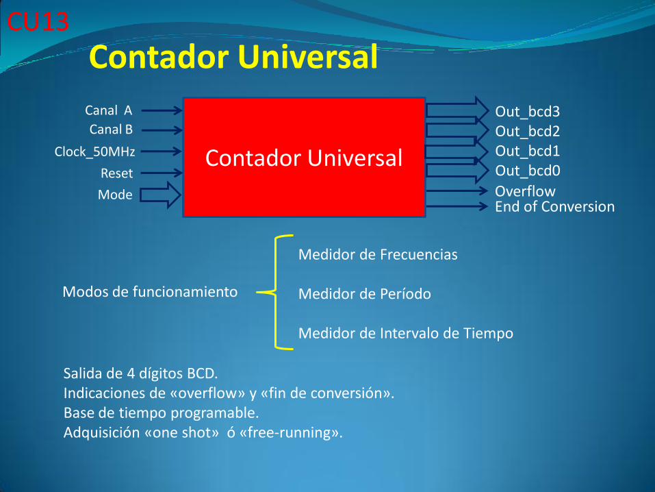
Contador Universal
Canal A
Clock_50MHz
Reset
Out_bcd3Out_bcd2Out_bcd1Out_bcd0
OverflowEnd of Conversion
Mode
Canal B
Medidor de Frecuencias
Medidor de Período
Medidor de Intervalo de Tiempo
Contador Universal
Modos de funcionamiento
Salida de 4 dígitos BCD.Indicaciones de «overflow» y «fin de conversión».Base de tiempo programable.Adquisición «one shot» ó «free-running».
CU13
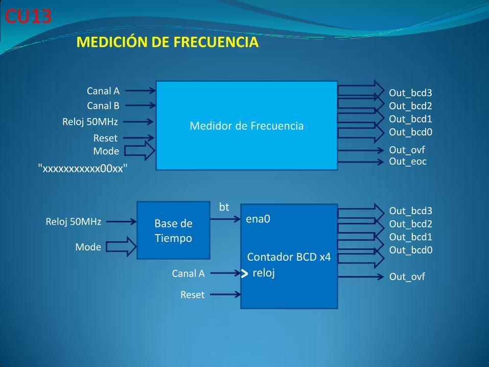
Medidor de Frecuencia
Canal A
Out_ovfOut_eoc
Mode
Canal B
Contador BCD x4
Out_bcd3Out_bcd2Out_bcd1Out_bcd0
Out_ovf
Out_bcd3Out_bcd2Out_bcd1Out_bcd0
Canal A
Reloj 50MHz
Reset
Base de Tiempo
ena0
reloj
Reloj 50MHz
Mode
Reset
"xxxxxxxxxxx00xx"
bt
MEDICIÓN DE FRECUENCIA
CU13
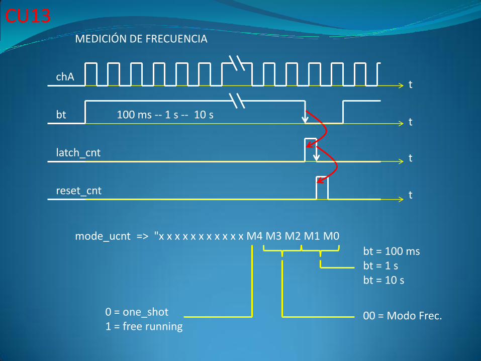
bt
latch_cnt
reset_cnt
t
t
t
t
chA
100 ms -- 1 s -- 10 s
mode_ucnt => "x x x x x x x x x x x M4 M3 M2 M1 M0
0 = one_shot1 = free running
bt = 100 msbt = 1 sbt = 10 s
00 = Modo Frec.
MEDICIÓN DE FRECUENCIA
CU13
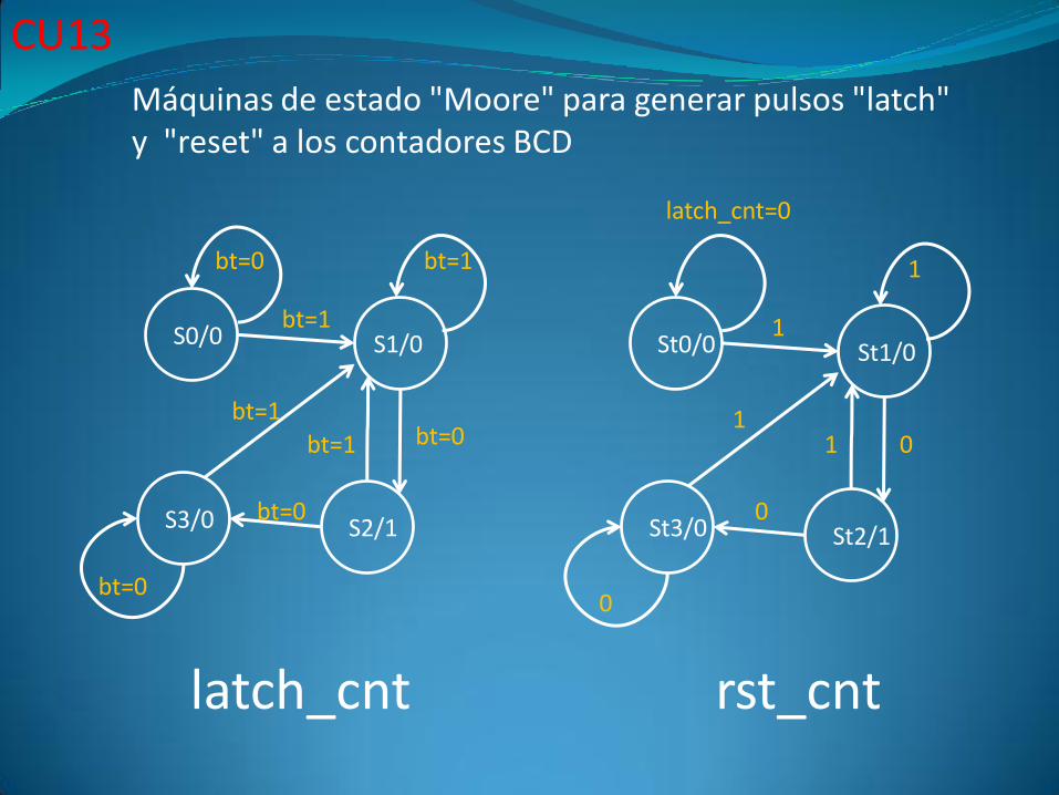
S0/0 S1/0
S3/0 S2/1
bt=0
bt=1
bt=0
bt=1
bt=0
bt=0bt=1
bt=1
St0/0 St1/0
St3/0 St2/1
latch_cnt=0
1
0
1
0
01
1
latch_cnt rst_cnt
Máquinas de estado "Moore" para generar pulsos "latch" y "reset" a los contadores BCD
CU13
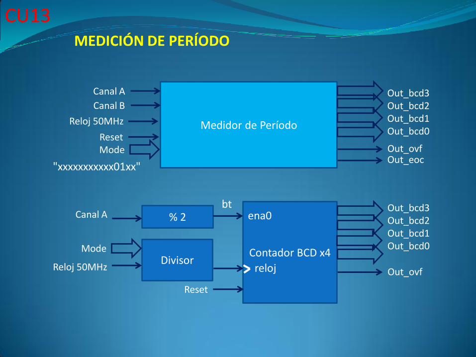
Medidor de Período
Canal A
Out_ovfOut_eoc
Mode
Canal B
Contador BCD x4
Out_bcd3Out_bcd2Out_bcd1Out_bcd0
Out_ovf
Out_bcd3Out_bcd2Out_bcd1Out_bcd0
Canal A
Reloj 50MHz
Reset
% 2 ena0
relojReloj 50MHz
Reset
"xxxxxxxxxxx01xx"
bt
DivisorMode
MEDICIÓN DE PERÍODO
CU13
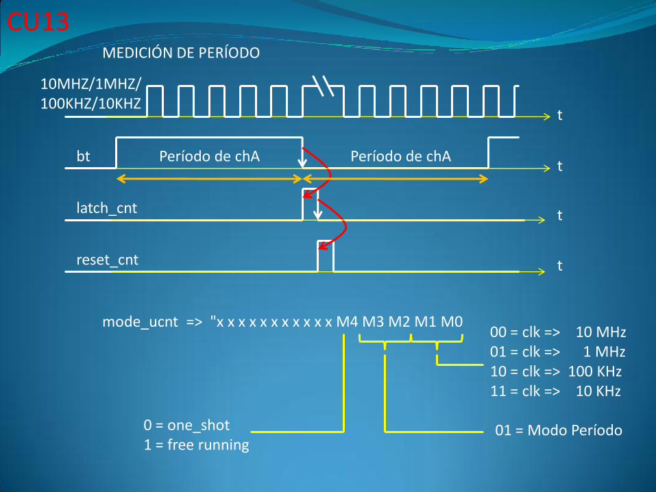
bt
latch_cnt
reset_cnt
t
t
t
t
10MHZ/1MHZ/100KHZ/10KHZ
mode_ucnt => "x x x x x x x x x x x M4 M3 M2 M1 M0
0 = one_shot1 = free running
01 = Modo Período
MEDICIÓN DE PERÍODO
Período de chA Período de chA
00 = clk => 10 MHz01 = clk => 1 MHz10 = clk => 100 KHz11 = clk => 10 KHz
CU13
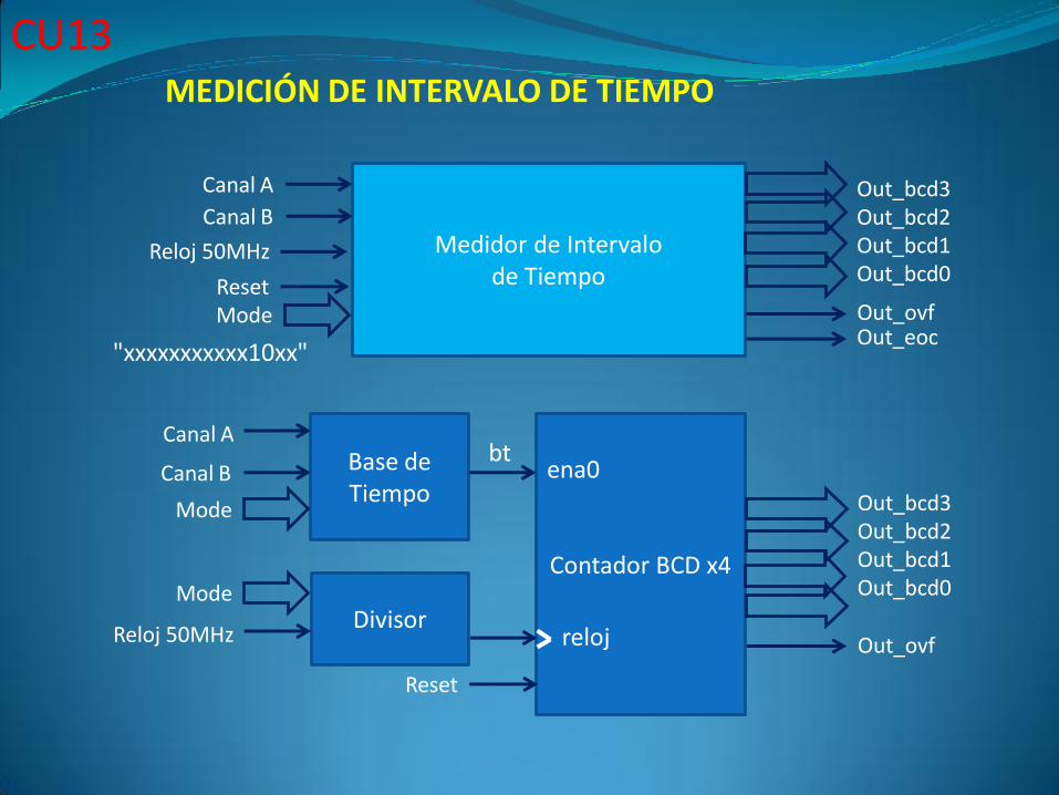
Medidor de Intervalode Tiempo
Canal A
Out_ovfOut_eoc
Mode
Canal B
Contador BCD x4
Out_bcd3Out_bcd2Out_bcd1Out_bcd0
Out_ovf
Out_bcd3Out_bcd2Out_bcd1Out_bcd0
Canal A
Reloj 50MHz
Reset
Base de Tiempo
ena0
relojReloj 50MHz
Reset
"xxxxxxxxxxx10xx"
bt
DivisorMode
Canal B
Mode
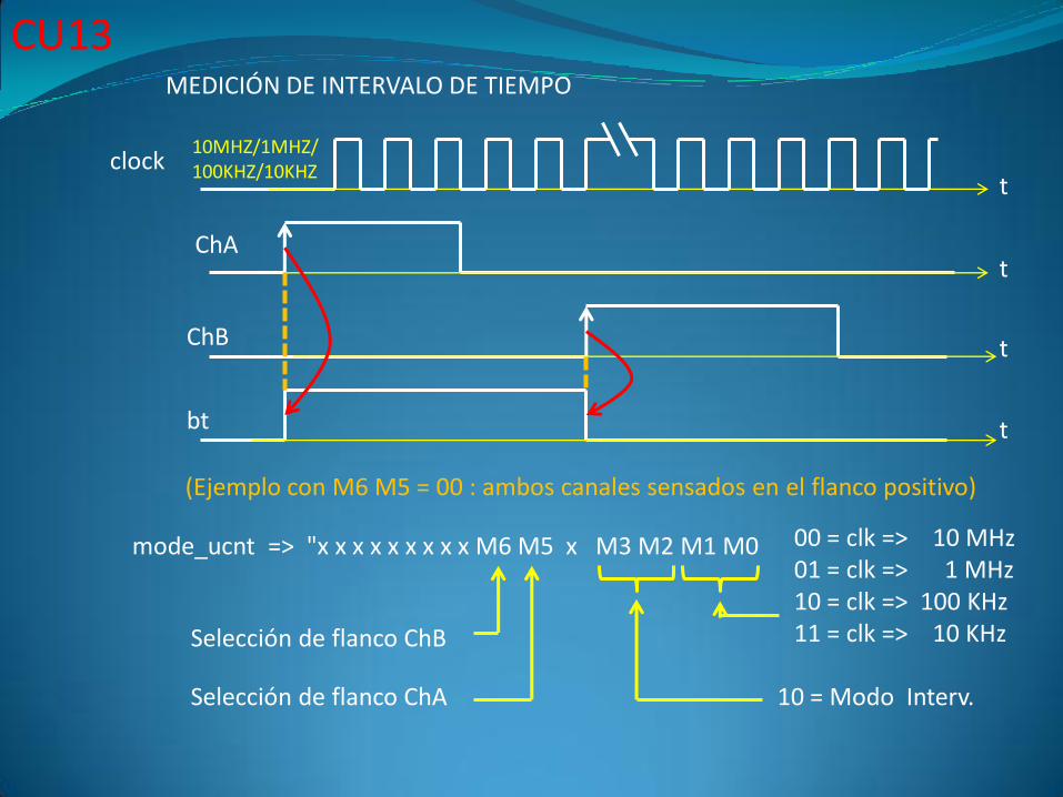
MEDICIÓN DE INTERVALO DE TIEMPO
CU13
bt
ChB
t
t
t
t
10MHZ/1MHZ/100KHZ/10KHZ
mode_ucnt => "x x x x x x x x x M6 M5 x M3 M2 M1 M0 00 = clk => 10 MHz01 = clk => 1 MHz10 = clk => 100 KHz11 = clk => 10 KHz
10 = Modo Interv.
MEDICIÓN DE INTERVALO DE TIEMPO
ChA
Selección de flanco ChA
Selección de flanco ChB
clock
(Ejemplo con M6 M5 = 00 : ambos canales sensados en el flanco positivo)
CU13
CU13
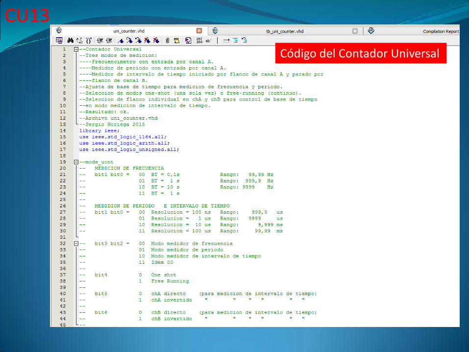
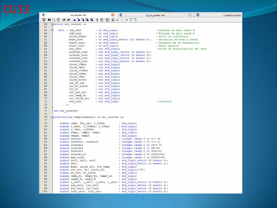
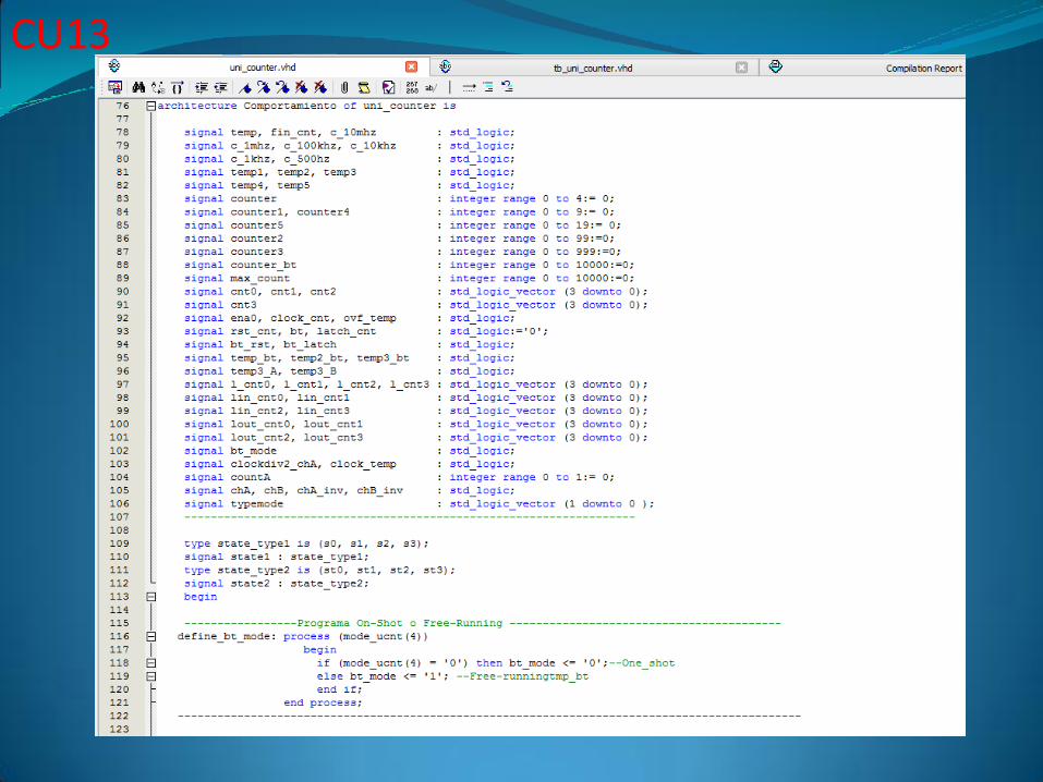
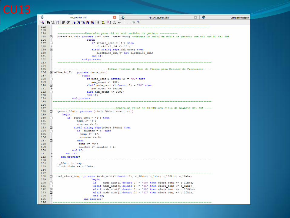
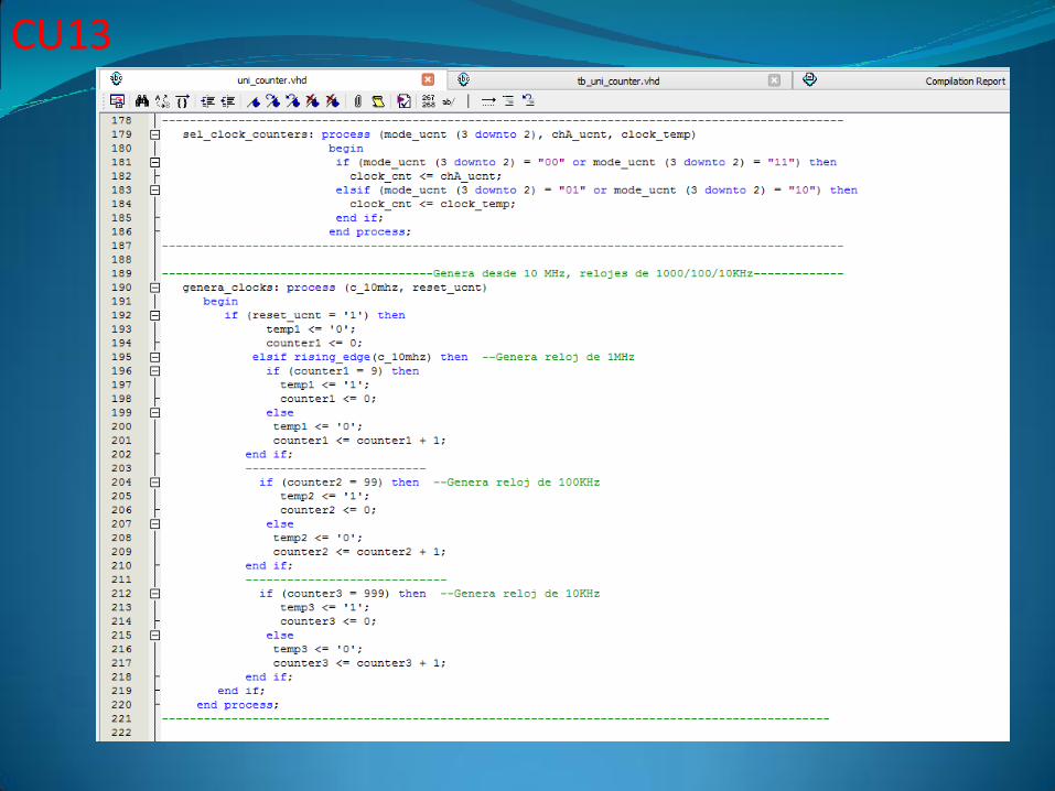
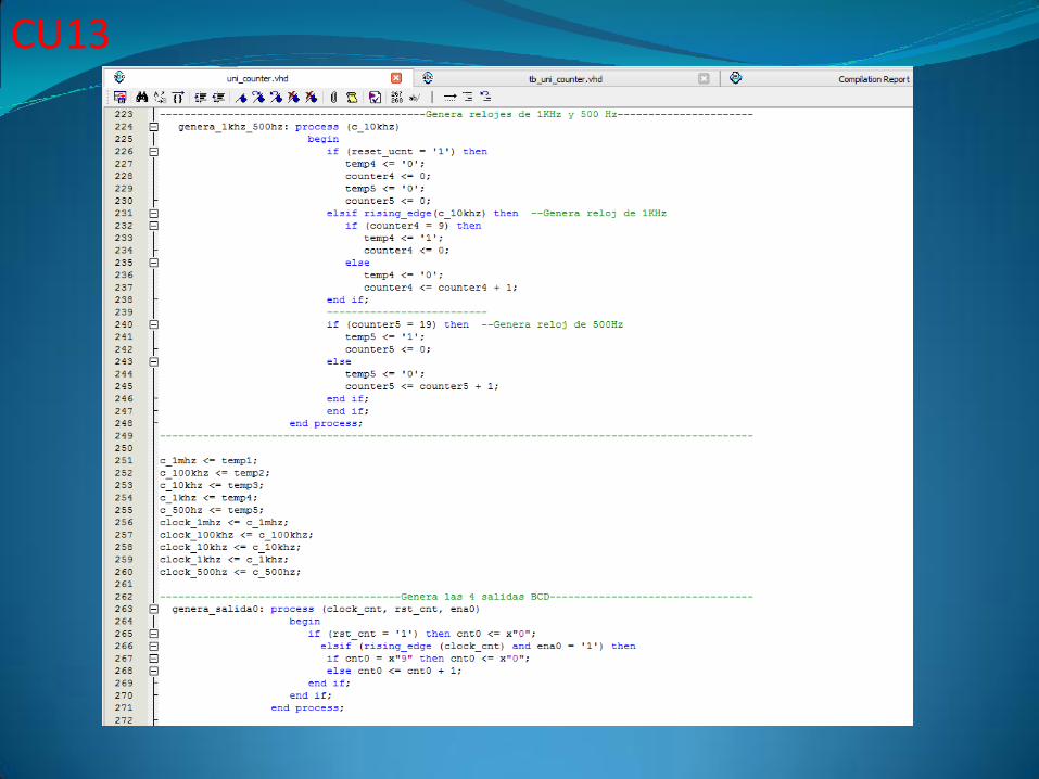
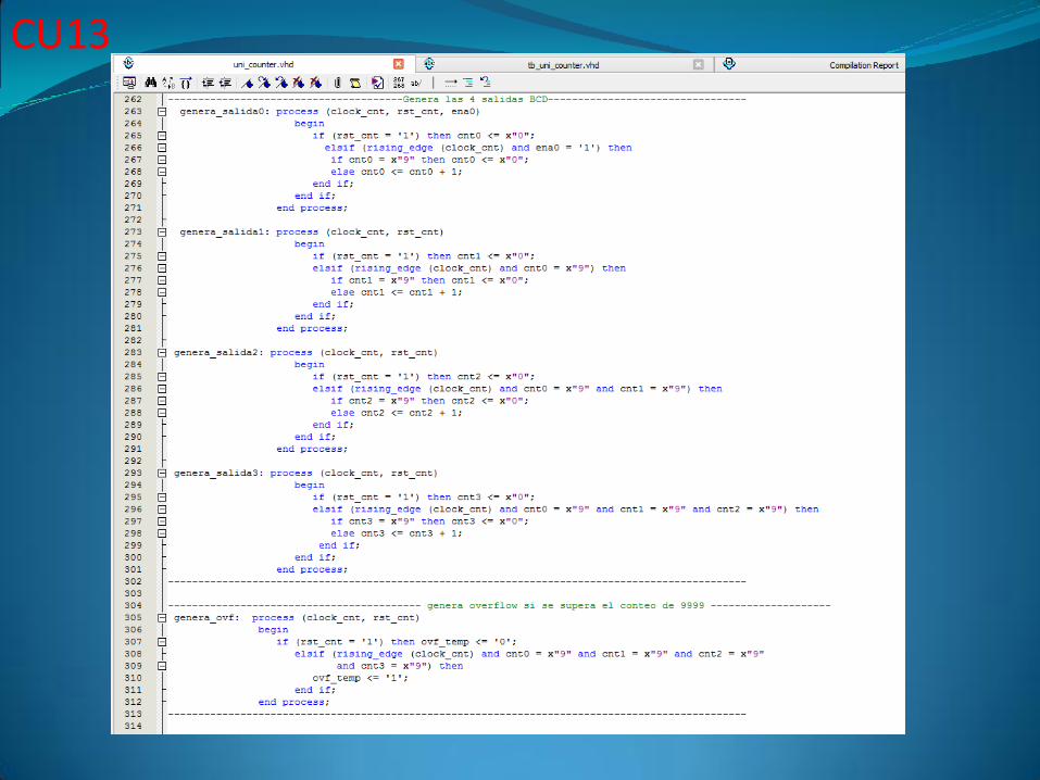
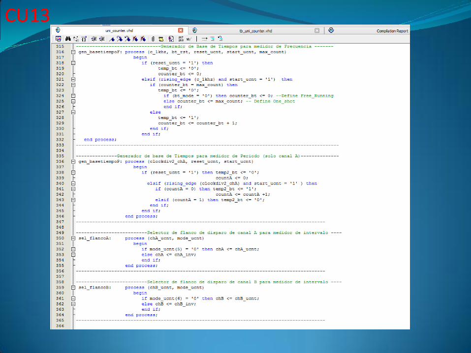
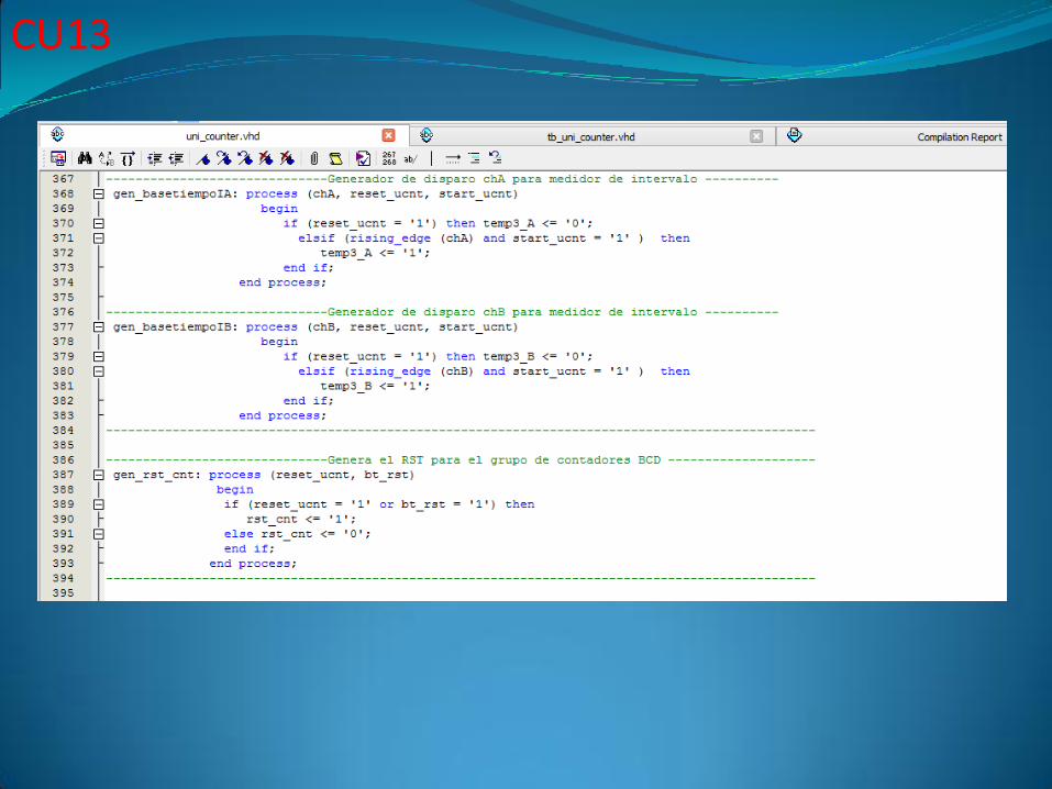
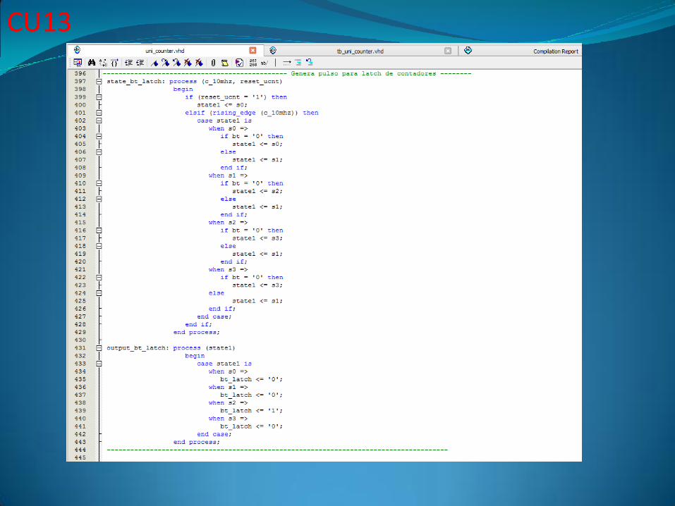
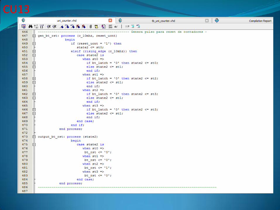
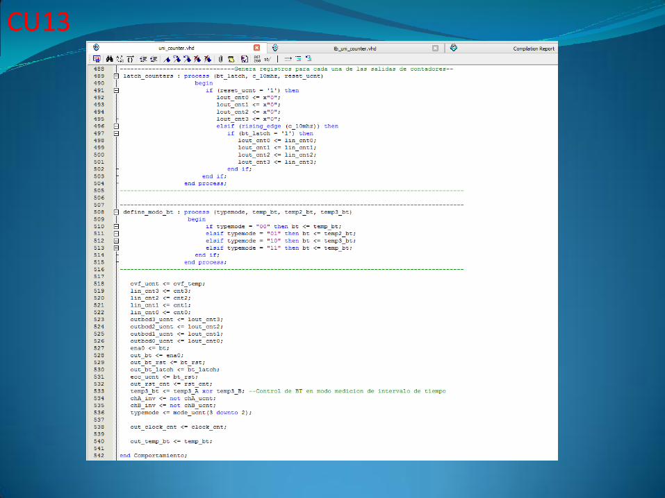
Código del Contador Universal
CU13
CU13
CU13
CU13
CU13
CU13
CU13
CU13
CU13
CU13
CU13
CU13
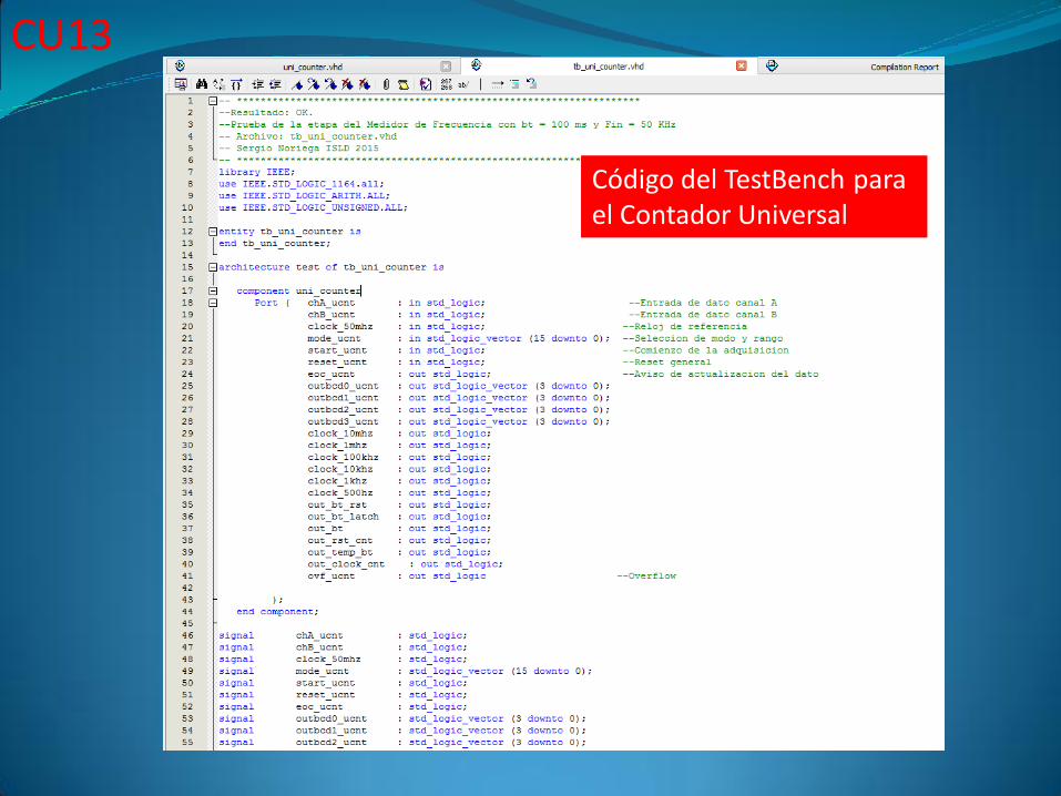
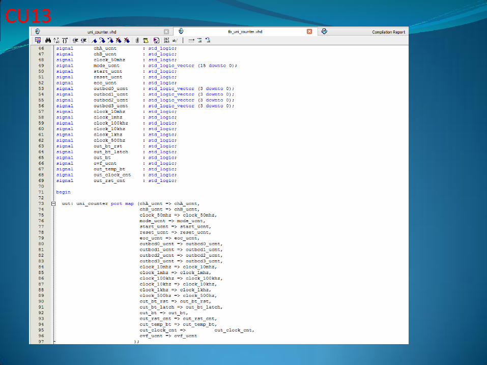
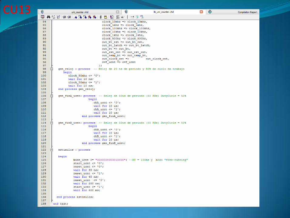
Código del TestBench para el Contador Universal
CU13
CU13
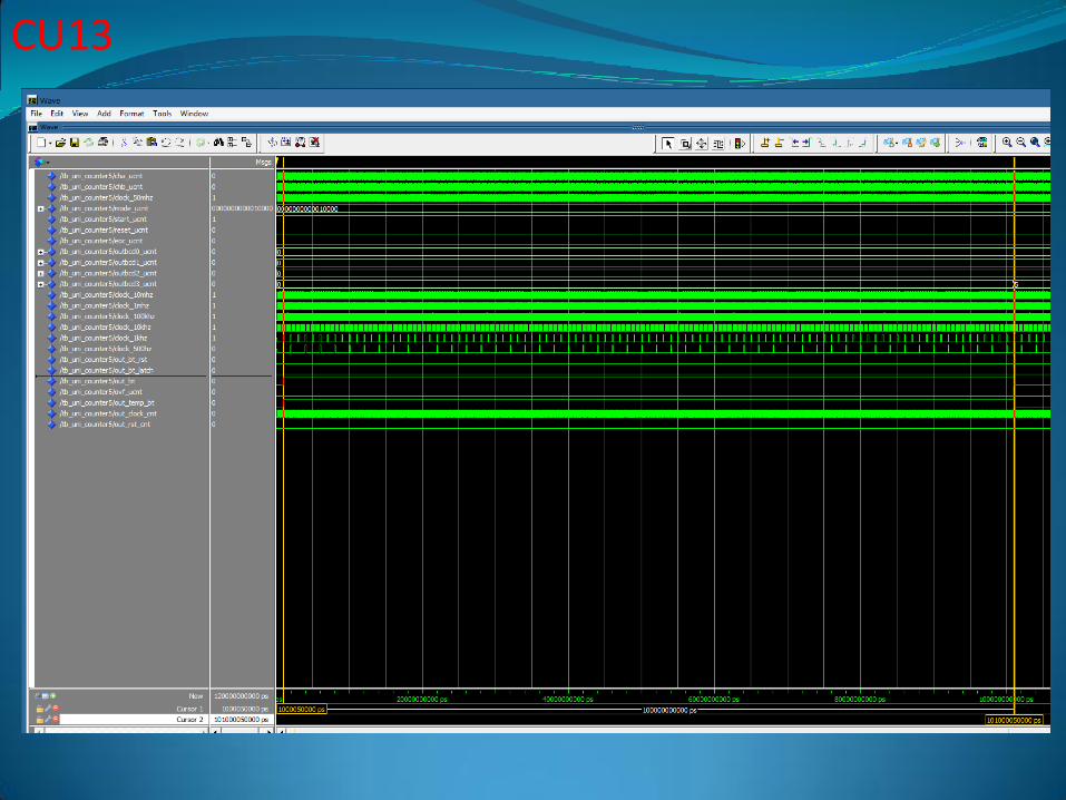
CU13
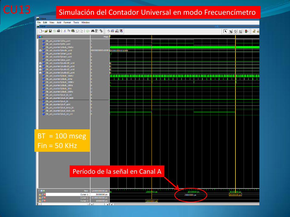
CU13 Simulación del Contador Universal en modo Frecuencímetro
BT = 100 msegFin = 50 KHz
Período de la señal en Canal A
CU13
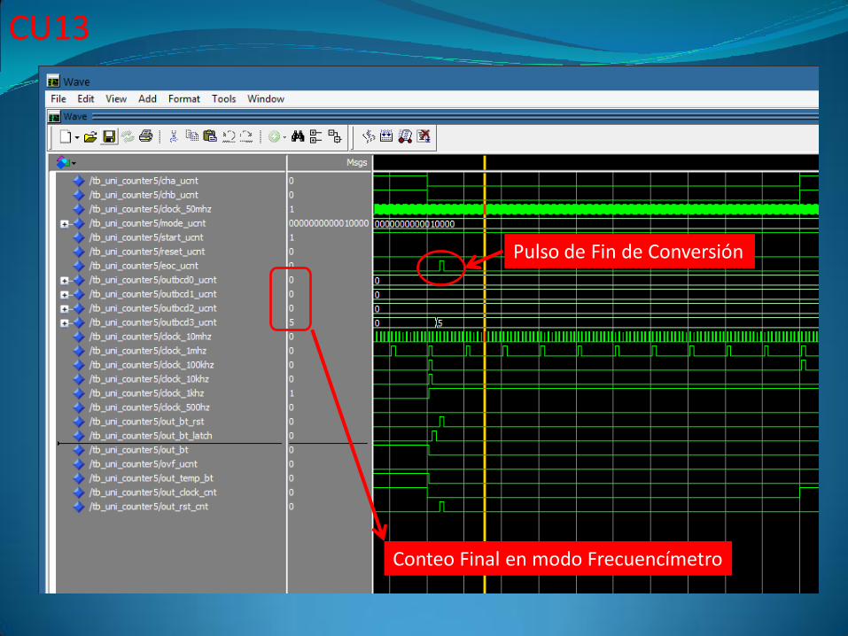
Pulso de Fin de Conversión
Conteo Final en modo Frecuencímetro
CU14
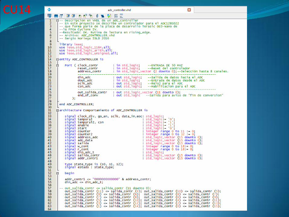
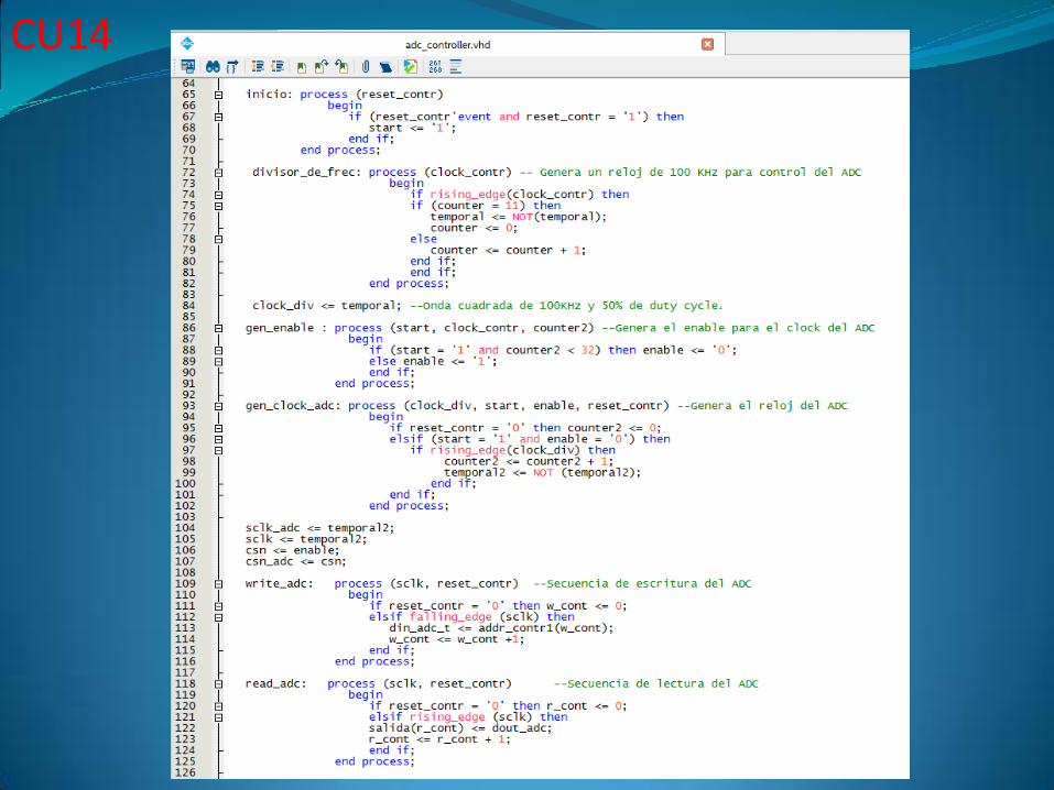
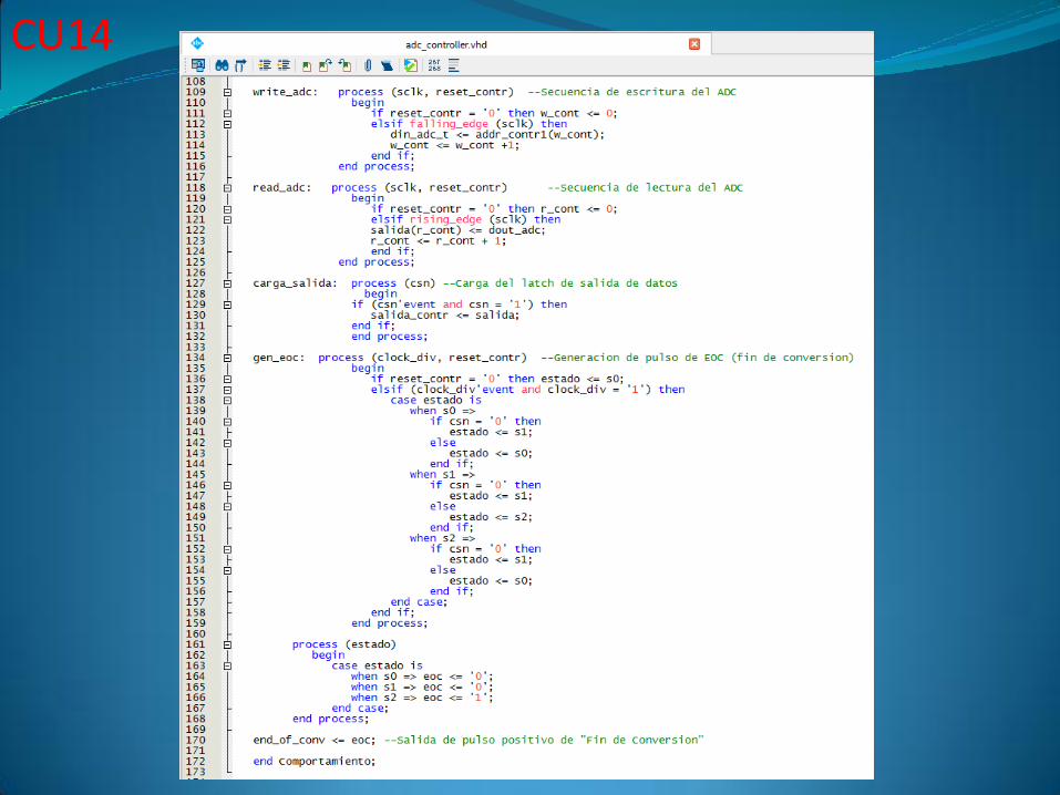
PROYECTO CU14
DISEÑO EN VHDL DE UN VOLTÍMETRO DIGITAL DE 4 DÍGITOS BCD INDEPENDIENTE, DE 8 CANALES AJUSTABLE POR DIP-SWITCHES.PERMITE MEDIR LA TENSIÓN DE ENTRADA CON RANGO DE 0 A 3.3 VDCDESDE LA PLACA DE0-NANO (CYCLONE IV), EMPLEANDO EL ADC SERIEPROVISTO EN LA MISMA.
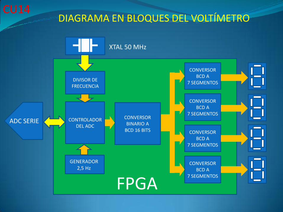
CONTROLADORDEL ADC
CONVERSORBINARIO A
BCD 16 BITS
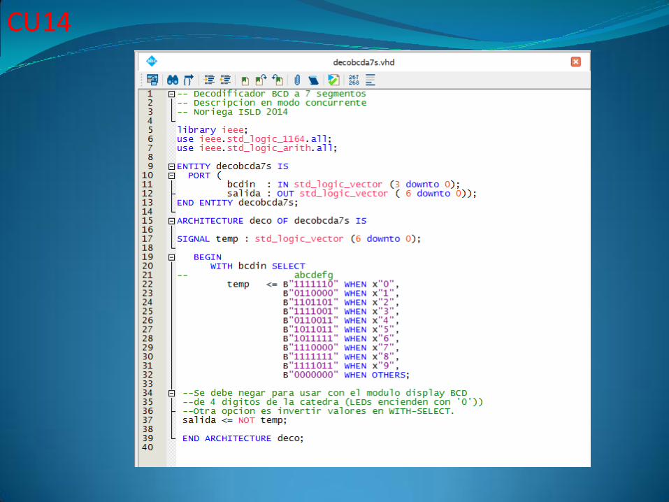
CONVERSORBCD A
7 SEGMENTOS
CONVERSORBCD A
7 SEGMENTOS
CONVERSORBCD A
7 SEGMENTOS
CONVERSORBCD A
7 SEGMENTOS
DIVISOR DEFRECUENCIA
XTAL 50 MHz
FPGA
ADC SERIE
GENERADOR2,5 Hz
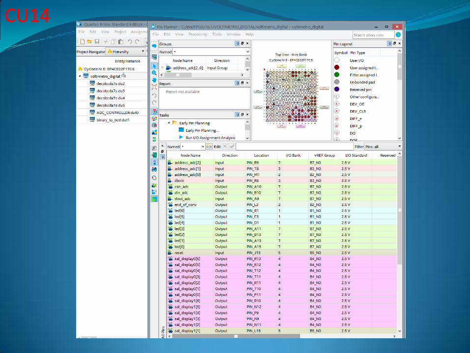
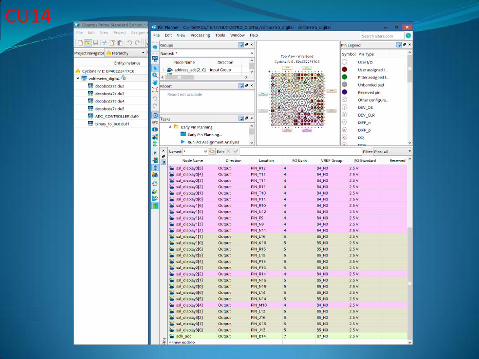
CU14DIAGRAMA EN BLOQUES DEL VOLTÍMETRO
CU14
CU14
CU14
CU14
CU14
CU14
CU14
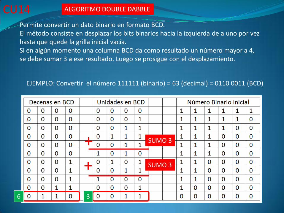
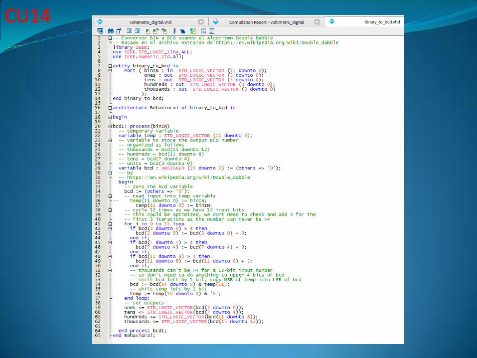
EJEMPLO: Convertir el número 111111 (binario) = 63 (decimal) = 0110 0011 (BCD)
ALGORITMO DOUBLE DABBLE
Permite convertir un dato binario en formato BCD.El método consiste en desplazar los bits binarios hacia la izquierda de a uno por vezhasta que quede la grilla inicial vacía.Si en algún momento una columna BCD da como resultado un número mayor a 4, se debe sumar 3 a ese resultado. Luego se prosigue con el desplazamiento.
SUMO 3
SUMO 3
6 3
+
+
CU14
CU14
CU14
CU14
CU14
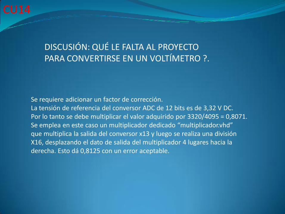
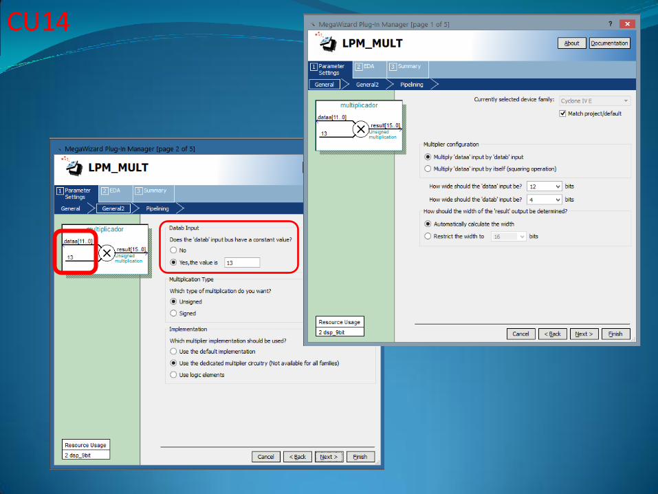
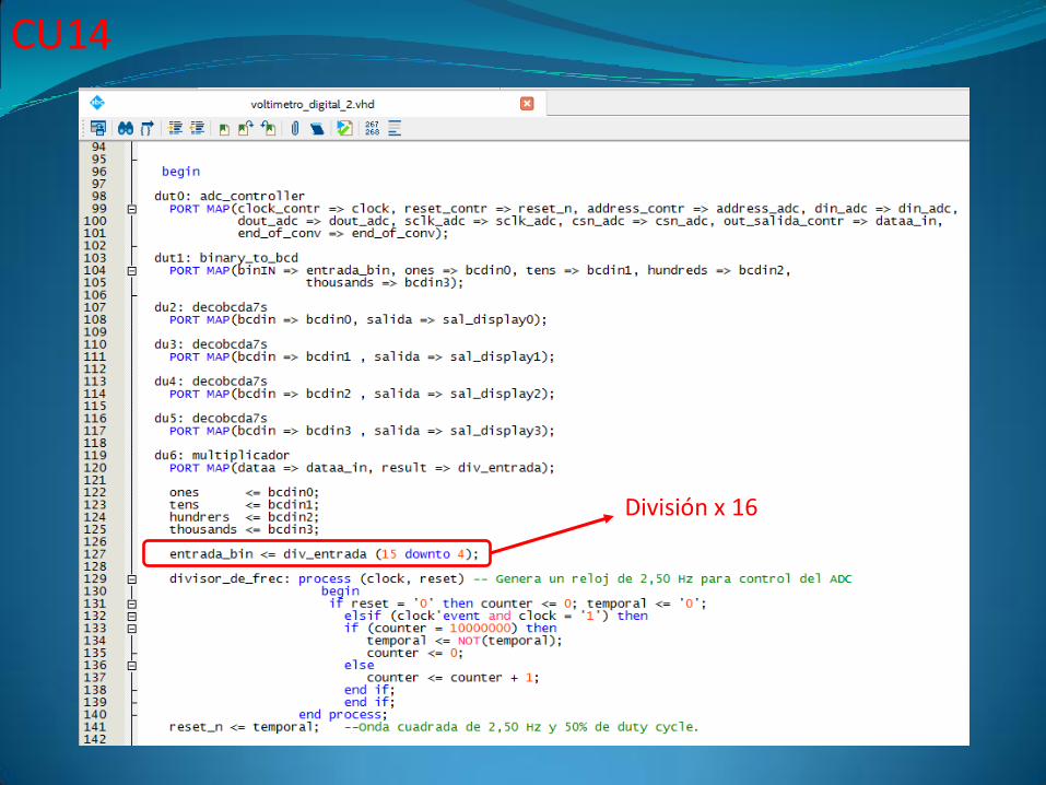
Se requiere adicionar un factor de corrección.La tensión de referencia del conversor ADC de 12 bits es de 3,32 V DC.Por lo tanto se debe multiplicar el valor adquirido por 3320/4095 = 0,8071.Se emplea en este caso un multiplicador dedicado “multiplicador.vhd”que multiplica la salida del conversor x13 y luego se realiza una divisiónX16, desplazando el dato de salida del multiplicador 4 lugares hacia laderecha. Esto dá 0,8125 con un error aceptable.
DISCUSIÓN: QUÉ LE FALTA AL PROYECTO PARA CONVERTIRSE EN UN VOLTÍMETRO ?.
CU14
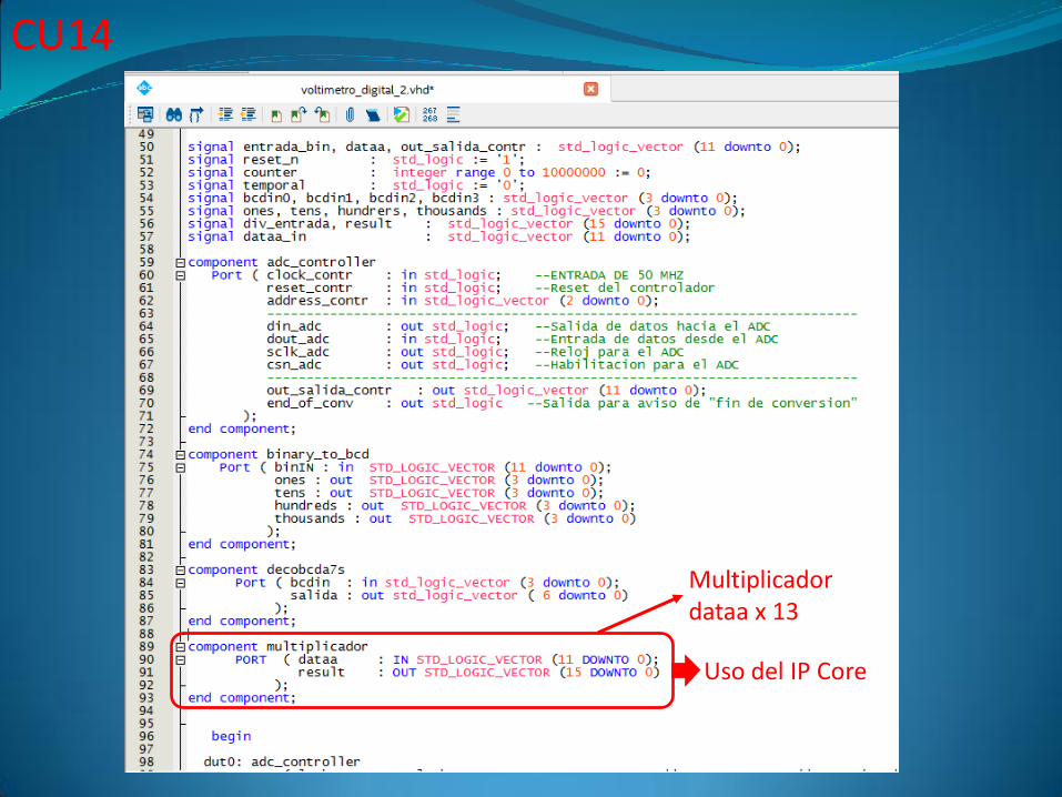
Multiplicador dataa x 13
Uso del IP Core
CU14
CU14
División x 16