Referˆencias Bibliogr´aficas€¦ · Dimensions 101 x 115 x 27 mm Weight 370 grams / 13 ounces...
15
Referˆ encias Bibliogr´ aficas [1] Defense Systems Inc.,Elements of C2 Theory, McLean, 1985. 1, 2.1 [2] Ince, A.N., Evrendilek, C., Wilhelmsen, D., Gezer, F.,Planning and Archi- tectural Design of Modern Command Control Communications and Infor- mation System, Kluwer, 1997. 1 [3] Pierre, Gustavo Moreira,Ambiente Integrado para Posicionamento em Opera¸ c˜ oes Militares, Disserta¸c˜ao de Mestrado, PUC–Rio, 2002. 1.3 [4] Seegar Jr., William D.,Deployable Command and Control System for Over the Horizon Small Boat Operations, Master‘s Thesis, Naval Postgraduate School,Monterey, CA, USA, 2006. 1.3 [5] Dispon´ ıvel em : www.aero.jor.br 2.1 [6] Penha, Osmar C,FlashDoutrin´ario, CIASC, 2010. 2.1 [7] Marinha do Brasil, Corpo de Fuzileiros Navais, CGCFN–60 Manual de Comando e Controle dos Grupamentos Operativos de Fuzileiros Navais,Rio de Janeiro, 2008. 2.1, 2.1 [8] Dispon´ ıvel em: http://tecnologia.uol.com.br/especiais/ultnot/ 2005/08/18/ult2888u81.jhtm 2.2.1 [9] Dispon´ ıvel em: http://www.sqlmagazine.com.br/Artigos/Postgre/01 Caracteristicas.asp 2.2.1 [10] Dispon´ ıvel em: http://www.tecgraf.puc-rio.br/iup/ 2.2.1 [11] Silva, C.A.; Seixas, R.B.,Integra¸ c˜ ao de Agentes Autˆ onomos e SIG em uma Arquitetura para Simula¸c˜ ao de Confrontos, Technical Report 01/2003. [12] Dispon´ ıvel em: http://www.tecgraf.puc-rio.br/cd/ 2.2.1 [13] Dispon´ ıvel em: http://www.tecgraf.puc-rio.br/im/ 2.2.1 [14] Dispon´ ıvel em: http://pt.wikipedia.org/wiki/Lua (linguagem de programa\unhbox\voidb@x\setbox\z@\hbox{c}\accent24c ∼ ao) 2.2.1 PUC-Rio - Certificação Digital Nº 0912820/CA
Transcript of Referˆencias Bibliogr´aficas€¦ · Dimensions 101 x 115 x 27 mm Weight 370 grams / 13 ounces...
Referencias Bibliograficas
[1] Defense Systems Inc.,Elements of C2 Theory, McLean, 1985. 1, 2.1
[2] Ince, A.N., Evrendilek, C., Wilhelmsen, D., Gezer, F.,Planning and Archi-
tectural Design of Modern Command Control Communications and Infor-
mation System, Kluwer, 1997. 1
[3] Pierre, Gustavo Moreira,Ambiente Integrado para Posicionamento em
Operacoes Militares, Dissertacao de Mestrado, PUC–Rio, 2002. 1.3
[4] Seegar Jr., William D.,Deployable Command and Control System for Over
the Horizon Small Boat Operations, Master‘s Thesis, Naval Postgraduate
School,Monterey, CA, USA, 2006. 1.3
[5] Disponıvel em : www.aero.jor.br 2.1
[6] Penha, Osmar C,Flash Doutrinario, CIASC, 2010. 2.1
[7] Marinha do Brasil, Corpo de Fuzileiros Navais, CGCFN–60 Manual de
Comando e Controle dos Grupamentos Operativos de Fuzileiros Navais,Rio
de Janeiro, 2008. 2.1, 2.1
[8] Disponıvel em: http://tecnologia.uol.com.br/especiais/ultnot/
2005/08/18/ult2888u81.jhtm 2.2.1
[9] Disponıvel em: http://www.sqlmagazine.com.br/Artigos/Postgre/01
Caracteristicas.asp 2.2.1
[10] Disponıvel em: http://www.tecgraf.puc-rio.br/iup/ 2.2.1
[11] Silva, C.A.; Seixas, R.B.,Integracao de Agentes Autonomos e SIG em uma
Arquitetura para Simulacao de Confrontos, Technical Report 01/2003.
[12] Disponıvel em: http://www.tecgraf.puc-rio.br/cd/ 2.2.1
[13] Disponıvel em: http://www.tecgraf.puc-rio.br/im/ 2.2.1
[14] Disponıvel em: http://pt.wikipedia.org/wiki/Lua (linguagem de
programa\unhbox\voidb@x\setbox\z@\hbox{c}\accent24c∼ao) 2.2.1
PU
C-R
io -
Cert
ific
ação D
igital N
º 0912820/C
A
Referencias Bibliograficas 75
[15] Disponıvel em: http://www.mundogeo.com.br/revistas-interna.php?
id noticia=7926 2.2.3
[16] Disponıvel em: http://aprs.gids.nl/nmea/ 2.2.3
[17] Seixas, R.B.,Banco de Dados do Sistema de Jogos Didaticos–SJD, Manual
2006. 2.2.4
[18] Disponıvel em: http://global.mobileaction.com/product/product
i-gotU GT-600.jsp (document), A.1
[19] Disponıvel em: http://www.fit-pc.com/web/fit-pc2/
fit-pc2-specifications/ (document), 2.3.2, A.2
[20] Disponıvel em: http://www.tekkeon.com/products-mypall-specs.
html (document), A.4
[21] Disponıvel em: http://www.mimomonitors.com/products/mimo-720-s
(document), A.5
[22] Disponıvel em: http://pt.wikipedia.org/wiki/Google Earth 2
[23] Disponıvel em: http://pt.wikilingue.com/es/Isobata 3.1
[24] Disponıvel em: http://pt.wikipedia.org/wiki/Curva de nivel 3.1
[25] Seixas, R.B.; Mediano, M.; Gattass, M.;Efficient Line-of-Sight Algorithms
for Real Terrain Data, III Simposio de Pesquisa Operacional e IV Simposio
de Logıstica da Marinha – SPOLM’99, 1999. 3.1
[26] Seixas, R.B.,Engine do Sistema de Jogos Didaticos–SJD, Manual 2006.
3.2, 3.2
[27] Ierusalimschy, Roberto, Programming in Lua, 2006, Lua.org, Second Edi-
tion.
[28] Campos, D.V.; Seixas, R. B;Command and Control: A low cost framework
to remotely monitor military training, Spring Simulation Multiconference,
2011.
PU
C-R
io -
Cert
ific
ação D
igital N
º 0912820/C
A
A
Tabelas com as Especificacoes dos Hardwares
3.2
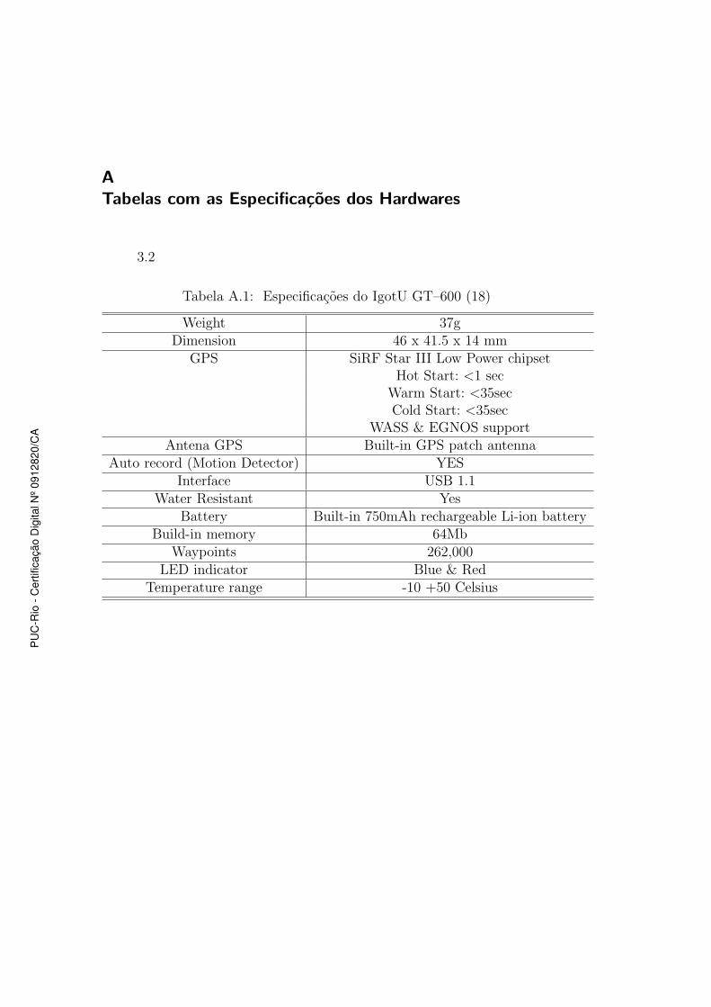
Tabela A.1: Especificacoes do IgotU GT–600 (18)
Weight 37gDimension 46 x 41.5 x 14 mm
GPS SiRF Star III Low Power chipsetHot Start: <1 sec
Warm Start: <35secCold Start: <35sec
WASS & EGNOS supportAntena GPS Built-in GPS patch antenna
Auto record (Motion Detector) YESInterface USB 1.1
Water Resistant YesBattery Built-in 750mAh rechargeable Li-ion battery
Build-in memory 64MbWaypoints 262,000
LED indicator Blue & RedTemperature range -10 +50 Celsius
PU
C-R
io -
Cert
ific
ação D
igital N
º 0912820/C
A
Apendice A. Tabelas com as Especificacoes dos Hardwares 77
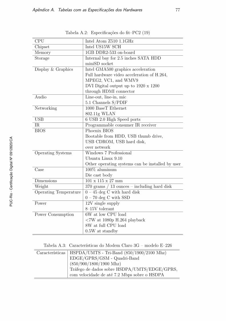
Tabela A.2: Especificacoes do fit–PC2 (19)
CPU Intel Atom Z510 1.1GHzChipset Intel US15W SCHMemory 1GB DDR2-533 on-boardStorage Internal bay for 2.5 inches SATA HDD
miniSD socketDisplay & Graphics Intel GMA500 graphics acceleration
Full hardware video acceleration of H.264,MPEG2, VC1, and WMV9DVI Digital output up to 1920 x 1200through HDMI connector
Audio Line-out, line-in, mic5.1 Channels S/PDIF
Networking 1000 BaseT Ethernet802.11g WLAN
USB 6 USB 2.0 High Speed portsIR Programmable consumer IR receiverBIOS Phoenix BIOS
Bootable from HDD, USB thumb drive,USB CDROM, USB hard disk,over network
Operating Systems Windows 7 ProfessionalUbuntu Linux 9.10Other operating systems can be installed by user
Case 100% aluminumDie cast body
Dimensions 101 x 115 x 27 mmWeight 370 grams / 13 ounces – including hard diskOperating Temperature 0 – 45 deg C with hard disk
0 – 70 deg C with SSDPower 12V single supply
8–15V tolerantPower Consumption 6W at low CPU load
<7W at 1080p H.264 playback8W at full CPU load0.5W at standby
Tabela A.3: Caracterısticas do Modem Claro 3G – modelo E–226
Caracterısticas HSPDA/UMTS - Tri-Band (850/1900/2100 Mhz)EDGE/GPRS/GSM - Quadri-Band(850/900/1800/1900 Mhz)Trafego de dados sobre HSDPA/UMTS/EDGE/GPRS,com velocidade de ate 7.2 Mbps sobre o HSDPA
PU
C-R
io -
Cert
ific
ação D
igital N
º 0912820/C
A
Apendice A. Tabelas com as Especificacoes dos Hardwares 78
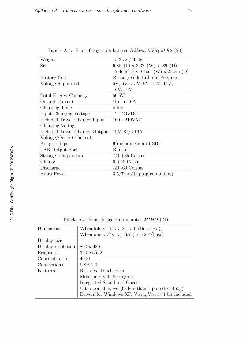
Tabela A.4: Especificacoes da bateria Tekkeon MP3450 R2 (20)
Weight 15.3 oz / 430gSize 6.85”(L) x 3.32”(W) x .89”(D)
17.4cm(L) x 8.4cm (W) x 2.3cm (D)Battery Cell Rechargeable Lithium PolymerVoltage Supported 5V, 6V, 7.5V, 9V, 12V, 14V,
16V, 19VTotal Energy Capacity 50 WhOutput Current Up to 4.0ACharging Time 4 hrsInput Charging Voltage 12 - 20VDCIncluded Travel Charger Input 100 - 240VACCharging VoltageIncluded Travel Charger Output 19VDC/3.16AVoltage/Output CurrentAdapter Tips 9(including mini USB)USB Output Port Built-inStorage Temperature -20 +35 CelsiusCharge 0 +40 CelsiusDischarge -20 -60 CelsiusExtra Power 3.5/7 hrs(Laptop computers)
Tabela A.5: Especificacoes do monitor MIMO (21)
Dimensions When folded: 7”x 5.25”x 1”(thickness),When open: 7”x 4.5”(tall) x 5.25”(base)
Display size 7”Display resolution 800 x 480Brightness 350 cd/m2Contrast ratio 400:1Connections USB 2.0Features Resistive Touchscreen
Monitor Pivots 90 degreesIntegrated Stand and CoverUltra-portable, weighs less than 1 pound(< 450g)Drivers for Windows XP, Vista, Vista 64-bit included
PU
C-R
io -
Cert
ific
ação D
igital N
º 0912820/C
A
B
Artigo publicado na Spring Simulation Multiconference 2011
PU
C-R
io -
Cert
ific
ação D
igital N
º 0912820/C
A
Command and Control:
A low cost framework to remotely
monitor military training
DANIEL DE VASCONCELOS CAMPOS 1
ROBERTO DE BEAUCLAIR SEIXAS 1,2
1PUC-Rio–Pontifical Catholic University
TECGRAF–Computer Graphics Technology Group
Rua Marques de Sao Vicente 225, 22453-900 Rio de Janeiro, RJ, Brazil
2IMPA–National Institute for Pure and Applied Mathematics
Estrada Dona Castorina 110, 22460-320 Rio de Janeiro, RJ, Brazil
Abstract. The Command and Control theory of John Boyd, a 20th century military strategist, allow us to intro-
duce computing techniques that are able to speed up the OODA loop (Observe–Orient–Decide–Act), especially
on observing and orienteering steps. This paper introduces a low cost framework capable of monitoring people,
vehicles, boats, or any other elements of interest, almost in real time. The goal of this design is to gather and
present the best possible information for decision makers in a Theater of Operations.
Keywords: Command and Control, OODA Loop, Military Training , Computer Graphics
1 INTRODUCTION
The success of any military operation is related to the abil-
ity to observe the battlefield state, decide and act in a mini-
mum time, guided by the current situation. This essentially
means having an OODA loop faster than the enemy force.
Based on the Boyd’s theory [1], we have been working on
the development of a framework that speeds up the observ-
ing and the orienteering steps by the application of comput-
ing techniques and portable electronic devices.
The system to support Command and Control – C2
has the goal of providing, in a unique environment, some
relevant information to the high command such as:
• Sketch graphically, in interactive time (near real time),
the monitored elements of a force deployed in theater
operations as well as the information about speed and
direction of travel of these elements;
• Provide information graphically, about the line-of-
sight, the weapon range and the radio range of the
monitored elements;
• Present thematic layers with various coordination and
control measures used in military operations, such as
goals, boundaries, landing beaches, among others;
• Record in a database positions occupied by monitored
elements allowing the reconstruction of their itinerary;
• Enable virtual positions simulation of monitored el-
ements, allowing the establishment of retransmission
stations, fire and visual coverage, in better conditions.
Achieving these goals, we intend to provide to the high
command an adequate tool to manage subordinate forces
deployed in theater operations during military training. As
a result, we still provide to the subordinate forces a use-
ful mechanism to navigate and quickly orient themselves in
relation to command and control measures established.
Figure 1: Monitored elements seen from monitor of stateful
station (red and blue icons)
2 ARCHITECTURE OF THE SYSTEM
For a better understanding of the proposed system it is es-
sential to explain its pipeline. Looking at the Figure 2
we can identify two main blocks: monitored element(s)
and stateful station. The monitored element contains some
portable electronics devices such as a small computer, a 3G
modem and a GPS logger. We will talk specifically about
Apêndice B. Artigo publicado na Spring Simulation Multiconference 2011 80P
UC
-Rio
- C
ert
ific
ação D
igital N
º 0912820/C
A
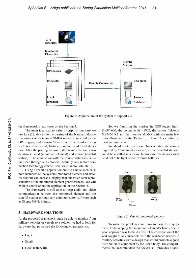
Figure 2: Arquitecture of the system to support C2
the framework’s hardwares on the Section 3.
The main idea was to write a script, in our case we
use Lua [2], able to do the parsing of the National Marine
Electronics Association – NMEA sentence, received by the
GPS logger, and transmit/store a record with information
such as current speed, latitude, longitude and travel direc-
tion. After the parsing we insert all this information in two
databases: local (monitored element) and remote (stateful
station). The connection with the remote databases is es-
tablished through a 3G modem. Actually, any remote con-
nection technology can be used (wi–fi, radio, satellite...).
Using a specific application built to handle such data,
both members of the system (monitored element and state-
ful station) can access a display that shows an icon repre-
sentative of the monitored element georeferenced. We will
explain details about the application on the Section 4.
The framework is still able to keep audio and video
communication between the monitored element and the
stateful station through any communication software such
as Skype, MSN, Ekiga...
3 HARDWARE SOLUTIONS
As the proposed framework must be able to monitor from
military vehicles or vessels to a soldier, we had to look for
hardware that possessed the following characteristics:
• Light
• Small
• Good battery life
So, we found on the market the GPS logger Igot–
U GT–600, the computer fit – PC2, the battery Tekkeon
MP3450 R2 and the monitor MIMO, with the main fea-
tures illustrated on the Tables 1, 4, 2 and 3 according to
these requirements.
We should note that these characteristics are mainly
required by “monitored element”, as the “stateful station”
could be installed in a room. In this case, the devices used
need not to be light or use external batteries.
Figure 3: Vest of monitored element
To solve the problem about how to carry this equip-
ment while keeping the monitored element’s hands free, a
good approach was to build a vest. The construction of the
vest sought to ally materials with the resistance needed to
military activities with a design that would promote a good
distribution of equipment by the user’s body. The compart-
ments that accommodate the devices still provides a satis-
Apêndice B. Artigo publicado na Spring Simulation Multiconference 2011 81P
UC
-Rio
- C
ert
ific
ação D
igital N
º 0912820/C
A
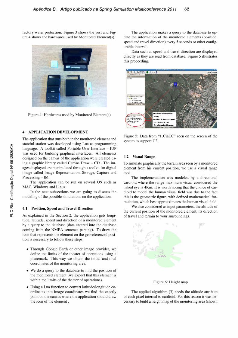
factory water protection. Figure 3 shows the vest and Fig-
ure 4 shows the hardwares used by Monitored Element(s).
Figure 4: Hardwares used by Monitored Element(s)
4 APPLICATION DEVELOPMENT
The application that runs both in the monitored element and
stateful station was developed using Lua as programming
language. A toolkit called Portable User Interface – IUP
was used for building graphical interfaces. All elements
designed on the canvas of the application were created us-
ing a graphic library called Canvas Draw – CD . The im-
ages displayed are manipulated through a toolkit for digital
image called Image Representation, Storage, Capture and
Processing – IM.
The application can be run on several OS such as
MAC, Windows and Linux.
In the next subsections we are going to discuss the
modeling of the possible simulations on the application.
4.1 Position, Speed and Travel Direction
As explained in the Section 2, the application gets longi-
tude, latitude, speed and direction of a monitored element
by a query to the database (data entered into the database
coming from the NMEA sentence parsing). To draw the
icon that represents the element on the georeferenced posi-
tion is necessary to follow these steps:
• Through Google Earth or other image provider, we
define the limits of the theater of operations using a
placemark. This way we obtain the initial and final
coordinates of the monitoring area.
• We do a query to the database to find the position of
the monitored element (we expect that this element is
within the limits of the theater of operations).
• Using a Lua function to convert latitude/longitude co-
ordinates into image coordinates we find the exactly
point on the canvas where the application should draw
the icon of the element .
The application makes a query to the database to up-
date the information of the monitored elements (position,
speed and travel direction) every 5 seconds or other config-
urable interval.
Data such as speed and travel direction are displayed
directly as they are read from database. Figure 5 illustrates
this proceeding.
Figure 5: Data from “1 CiaCC” seen on the screen of the
system to support C2
4.2 Visual Range
To simulate graphically the terrain area seen by a monitored
element from his current position, we use a visual range
tool.
The implementation was modeled by a directional
cardioid where the range maximum visual considered the
naked eye is 4Km. It is worth noting that the choice of car-
dioid to model the human visual field was due to the fact
this is the geometric figure, with defined mathematical for-
mulation, which best approaximates the human visual field.
We also considered as input parameters, the altitude of
the current position of the monitored element, its direction
of travel and terrain to your surroundings.
Figure 6: Height map
The applied algorithm [3] needs the altitude attribute
of each pixel internal to cardioid. For this reason it was ne-
cessary to build a height map of the monitoring area (shown
Apêndice B. Artigo publicado na Spring Simulation Multiconference 2011 82P
UC
-Rio
- C
ert
ific
ação D
igital N
º 0912820/C
A
in Figure 6).
The algorithm compares the altitude of the monitored
element position with the altitude of each pixel internal to
cardioid (obtained from height map). This comparison is
done based on the current position to the edge of the car-
dioid and 0 to 359 degrees. If the altitude of the monitored
element is greater, the pixel is colored green. If the alti-
tude is less, the procedure is stopped and restarted in a new
direction until it completes 360 degrees.
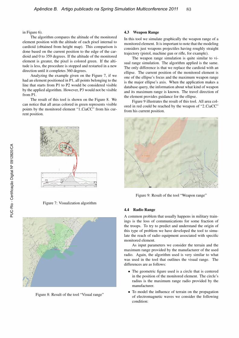
Analyzing the example given on the Figure 7, if we
had an element positioned in P1, all points belonging to the
line that starts from P1 to P2 would be considered visible
by the applied algorithm. However, P3 would not be visible
from P1.
The result of this tool is shown on the Figure 8. We
can notice that all areas colored in green represents visible
points by the monitored element “1 CiaCC” from his cur-
rent position.
Figure 7: Visualization algorithm
Figure 8: Result of the tool “Visual range”
4.3 Weapon Range
In this tool we simulate graphically the weapon range of a
monitored element. It is important to note that the modeling
considers just weapons projectiles having roughly straight
trajectory (pistol, machine gun or rifle, for example).
The weapon range simulation is quite similar to vi-
sual range simulation. The algorithm applied is the same.
The only difference is that we replace the cardioid with an
ellipse. The current position of the monitored element is
one of the ellipse’s focus and the maximum weapon range
is the major ellipse’s axis. When the application makes a
database query, the information about what kind of weapon
and its maximum range is known. The travel direction of
the element provides guidance for the ellipse.
Figure 9 illustrates the result of this tool. All area col-
ored in red could be reached by the weapon of “2 CiaCC”
from his current position.
Figure 9: Result of the tool “Weapon range”
4.4 Radio Range
A common problem that usually happens in military train-
ings is the loss of communications for some fraction of
the troops. To try to predict and understand the origin of
this type of problem we have developed the tool to simu-
late the reach of radio equipment associated with specific
monitored element.
As input parameters we consider the terrain and the
maximum range provided by the manufacturer of the used
radio. Again, the algorithm used is very similar to what
was used in the tool that outlines the visual range. The
differences are as follows:
• The geometric figure used is a circle that is centered
in the position of the monitored element. The circle’s
radius is the maximum range radio provided by the
manufacturer.
• To model the influence of terrain on the propagation
of electromagnetic waves we consider the following
condition:
Apêndice B. Artigo publicado na Spring Simulation Multiconference 2011 83P
UC
-Rio
- C
ert
ific
ação D
igital N
º 0912820/C
A

If there is any point internal to the circle (previously
explained) 100 meters of altitude above the position
of the monitored element it will block the electromag-
netic waves from there.
• All points colored in blue represent the area reached
by the radio electromagnetic waves.
Figure 10 shows the result of this tool.
Figure 10: Result of the tool “Radio range”
4.5 Radar Simulation
The movement of approach of various vectors that carry
troops from ship to landing beaches, in amphibious oper-
ations in military training, is a time that requires great co-
ordination and control of the upper echelon. Depending on
the landing beach, the existence of various natural obstacles
in this path can easily damage or even prevent the vectors
to reach the planned beach .
To assist this approach we have developed a tool that
simulates the behavior of a radar providing to the monitored
element data such as the distance from its current position
to the nearest point above sea level.
We modeled this tool with a circle centered at the cur-
rent position of monitored element. The radious of the cir-
cle (radar range) is configurable. Applying the similar al-
gorithm of visual range tool, a scan is performed inside the
circle where all points above sea level are returned. In this
case we consider the information brought by the nautical
charts in order to discover points above sea level.
We can check the result of this tool in Figure 11.
4.6 Echo Sounder Simulation
Another important information during the transfer of troops
from ships to landing beaches is the current depth along the
navigation path. Thus to provide this information we have
developed the tool “Echo Sounder”.
The system requires the construction of a depth map
to be able to return the depth of any point. We can see in
Figure 11: Result of the tool “Radar Simulation”
Figure 12 the depth map from Guanabara Bay. The depth
map construction is based on the nautical chart’s lines that
joins points with the same depth.
Figure 12: Construction of a Depth Map
4.7 Virtual Position
The problem to be treated by this tool is the adequate es-
tablishment of coverage of communication/fire in an area
of operations.
The user can simulate the range of the radio of any el-
ement, through the radio range tool, and find out all areas
not covered by the scope of radio as a function of the limit
of its range or the presence of a mountain, for example. In
this case, the user can simulate through the tool “Virtual
Position” the positioning of a selected element in any point
of the theater of operations executing the task of a retrans-
mission post.
This is too a quite useful tool to establish the ideal
cover fires of an area. Using the weapon range tool the
high command can simulate all area that the arming of a
specific monitored element(s) can achieve. Thus, if there
is an important area that is not being covered, through the
virtual positioning tool, we can check the best position(s)
Apêndice B. Artigo publicado na Spring Simulation Multiconference 2011 84P
UC
-Rio
- C
ert
ific
ação D
igital N
º 0912820/C
A
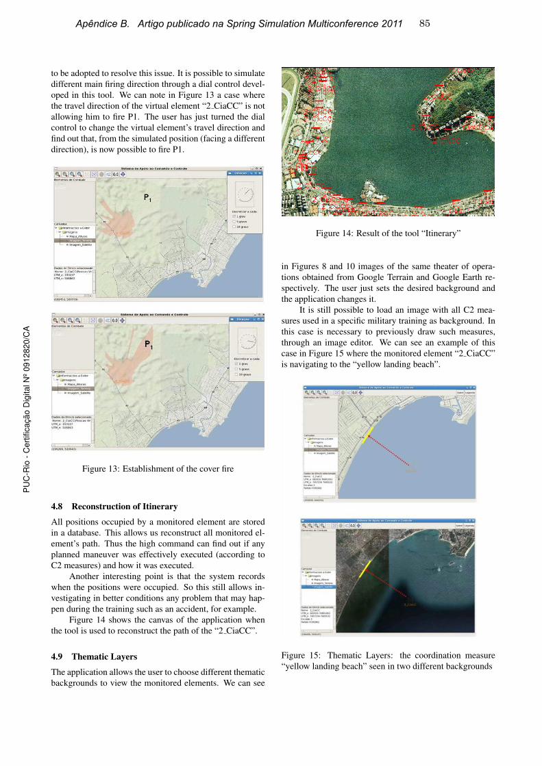
to be adopted to resolve this issue. It is possible to simulate
different main firing direction through a dial control devel-
oped in this tool. We can note in Figure 13 a case where
the travel direction of the virtual element “2 CiaCC” is not
allowing him to fire P1. The user has just turned the dial
control to change the virtual element’s travel direction and
find out that, from the simulated position (facing a different
direction), is now possible to fire P1.
Figure 13: Establishment of the cover fire
4.8 Reconstruction of Itinerary
All positions occupied by a monitored element are stored
in a database. This allows us reconstruct all monitored el-
ement’s path. Thus the high command can find out if any
planned maneuver was effectively executed (according to
C2 measures) and how it was executed.
Another interesting point is that the system records
when the positions were occupied. So this still allows in-
vestigating in better conditions any problem that may hap-
pen during the training such as an accident, for example.
Figure 14 shows the canvas of the application when
the tool is used to reconstruct the path of the “2 CiaCC”.
4.9 Thematic Layers
The application allows the user to choose different thematic
backgrounds to view the monitored elements. We can see
Figure 14: Result of the tool “Itinerary”
in Figures 8 and 10 images of the same theater of opera-
tions obtained from Google Terrain and Google Earth re-
spectively. The user just sets the desired background and
the application changes it.
It is still possible to load an image with all C2 mea-
sures used in a specific military training as background. In
this case is necessary to previously draw such measures,
through an image editor. We can see an example of this
case in Figure 15 where the monitored element “2 CiaCC”
is navigating to the “yellow landing beach”.
Figure 15: Thematic Layers: the coordination measure
“yellow landing beach” seen in two different backgrounds
Apêndice B. Artigo publicado na Spring Simulation Multiconference 2011 85P
UC
-Rio
- C
ert
ific
ação D
igital N
º 0912820/C
A
5 CONCLUSIONS
The implementation of the system to support C2 contributes
to an almost immediate observation of all subordinate units
of a force deployed on the operations area by high com-
mand. The framework still provides to the monitored el-
ement an important mechanism to navigate on the theater
of operations and, simultaneously, transmit images, in real
time, from any deployed element to the high command.
This is quite useful to speed up the observation step from
OODA loop. However it is important to note that the frame-
work should be integrated with other information systems
to obtain data about opposite party in double sided action
military training.
The simulation tools developed help decision-makers
to orient themselves more quickly. Thus we believe that
we have contributed to quicken the step of guidance from
OODA loop.
6 FUTURE WORKS
We intend to study mechanisms for integrating information
systems to the framework. This integration is an attempt
to display both party to decision-makers in a double sided
action military training.
An important issue to be improved is the remote con-
nection used by the framework. Nowadays we are keeping
the connection between monitored element and the stateful
station through a 3G modem. However this kind of connec-
tion is not very stable nor secure. So a possible solution is
to investigate whether some military radio is able to main-
tain this connection in better conditions.
We also intend to improve the modeling of the tool
“Weapon Range”. The idea is to model other kinds of pro-
jectiles trajectory. Thus we will be able to simulate the
cover fires of other kinds of weapons such as mortars and
howitzers, for example.
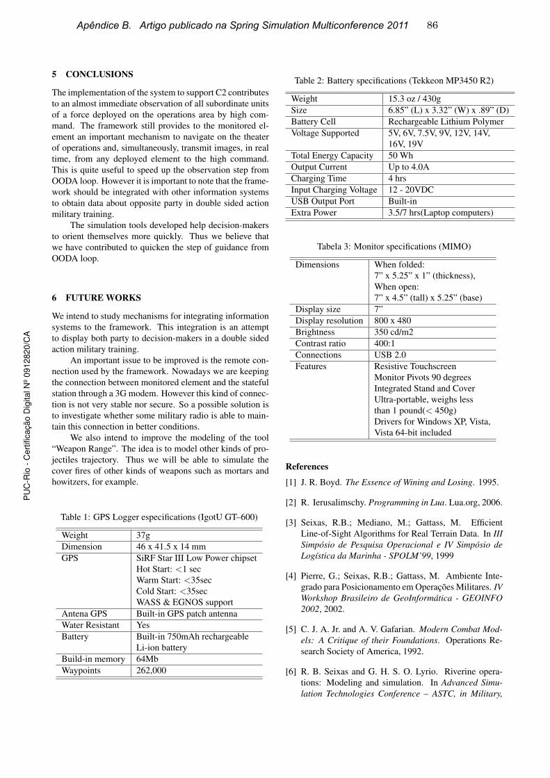
Table 1: GPS Logger especifications (IgotU GT–600)
Weight 37g
Dimension 46 x 41.5 x 14 mm
GPS SiRF Star III Low Power chipset
Hot Start: <1 sec
Warm Start: <35sec
Cold Start: <35sec
WASS & EGNOS support
Antena GPS Built-in GPS patch antenna
Water Resistant Yes
Battery Built-in 750mAh rechargeable
Li-ion battery
Build-in memory 64Mb
Waypoints 262,000
Table 2: Battery specifications (Tekkeon MP3450 R2)
Weight 15.3 oz / 430g
Size 6.85” (L) x 3.32” (W) x .89” (D)
Battery Cell Rechargeable Lithium Polymer
Voltage Supported 5V, 6V, 7.5V, 9V, 12V, 14V,
16V, 19V
Total Energy Capacity 50 Wh
Output Current Up to 4.0A
Charging Time 4 hrs
Input Charging Voltage 12 - 20VDC
USB Output Port Built-in
Extra Power 3.5/7 hrs(Laptop computers)
Tabela 3: Monitor specifications (MIMO)
Dimensions When folded:
7” x 5.25” x 1” (thickness),
When open:
7” x 4.5” (tall) x 5.25” (base)
Display size 7”
Display resolution 800 x 480
Brightness 350 cd/m2
Contrast ratio 400:1
Connections USB 2.0
Features Resistive Touchscreen
Monitor Pivots 90 degrees
Integrated Stand and Cover
Ultra-portable, weighs less
than 1 pound(< 450g)
Drivers for Windows XP, Vista,
Vista 64-bit included
References
[1] J. R. Boyd. The Essence of Wining and Losing. 1995.
[2] R. Ierusalimschy. Programming in Lua. Lua.org, 2006.
[3] Seixas, R.B.; Mediano, M.; Gattass, M. Efficient
Line-of-Sight Algorithms for Real Terrain Data. In III
Simposio de Pesquisa Operacional e IV Simposio de
Logıstica da Marinha - SPOLM’99, 1999
[4] Pierre, G.; Seixas, R.B.; Gattass, M. Ambiente Inte-
grado para Posicionamento em Operacoes Militares. IV
Workshop Brasileiro de GeoInformatica - GEOINFO
2002, 2002.
[5] C. J. A. Jr. and A. V. Gafarian. Modern Combat Mod-
els: A Critique of their Foundations. Operations Re-
search Society of America, 1992.
[6] R. B. Seixas and G. H. S. O. Lyrio. Riverine opera-
tions: Modeling and simulation. In Advanced Simu-
lation Technologies Conference – ASTC, in Military,
Apêndice B. Artigo publicado na Spring Simulation Multiconference 2011 86P
UC
-Rio
- C
ert
ific
ação D
igital N
º 0912820/C
A
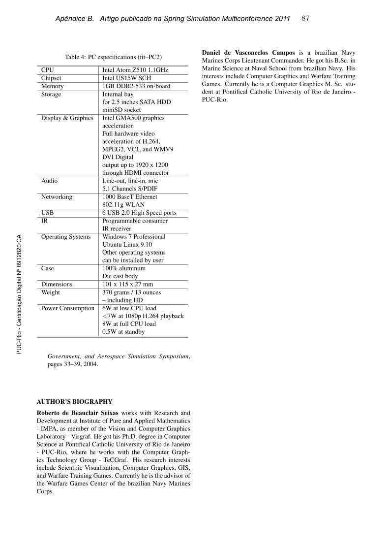
Table 4: PC especifications (fit–PC2)
CPU Intel Atom Z510 1.1GHz
Chipset Intel US15W SCH
Memory 1GB DDR2-533 on-board
Storage Internal bay
for 2.5 inches SATA HDD
miniSD socket
Display & Graphics Intel GMA500 graphics
acceleration
Full hardware video
acceleration of H.264,
MPEG2, VC1, and WMV9
DVI Digital
output up to 1920 x 1200
through HDMI connector
Audio Line-out, line-in, mic
5.1 Channels S/PDIF
Networking 1000 BaseT Ethernet
802.11g WLAN
USB 6 USB 2.0 High Speed ports
IR Programmable consumer
IR receiver
Operating Systems Windows 7 Professional
Ubuntu Linux 9.10
Other operating systems
can be installed by user
Case 100% aluminum
Die cast body
Dimensions 101 x 115 x 27 mm
Weight 370 grams / 13 ounces
– including HD
Power Consumption 6W at low CPU load
<7W at 1080p H.264 playback
8W at full CPU load
0.5W at standby
Government, and Aerospace Simulation Symposium,
pages 33–39, 2004.
AUTHOR’S BIOGRAPHY
Roberto de Beauclair Seixas works with Research and
Development at Institute of Pure and Applied Mathematics
- IMPA, as member of the Vision and Computer Graphics
Laboratory - Visgraf. He got his Ph.D. degree in Computer
Science at Pontifical Catholic University of Rio de Janeiro
- PUC-Rio, where he works with the Computer Graph-
ics Technology Group - TeCGraf. His research interests
include Scientific Visualization, Computer Graphics, GIS,
and Warfare Training Games. Currently he is the advisor of
the Warfare Games Center of the brazilian Navy Marines
Corps.
Daniel de Vasconcelos Campos is a brazilian Navy
Marines Corps Lieutenant Commander. He got his B.Sc. in
Marine Science at Naval School from brazilian Navy. His
interests include Computer Graphics and Warfare Training
Games. Currently he is a Computer Graphics M. Sc. stu-
dent at Pontifical Catholic University of Rio de Janeiro -
PUC-Rio.
Apêndice B. Artigo publicado na Spring Simulation Multiconference 2011 87P
UC
-Rio
- C
ert
ific
ação D
igital N
º 0912820/C
A

Apendice B. Artigo publicado na Spring Simulation Multiconference 2011 88P
UC
-Rio
- C
ert
ific
ação D
igital N
º 0912820/C
A