Reporte Cortos 1 - Completo
10
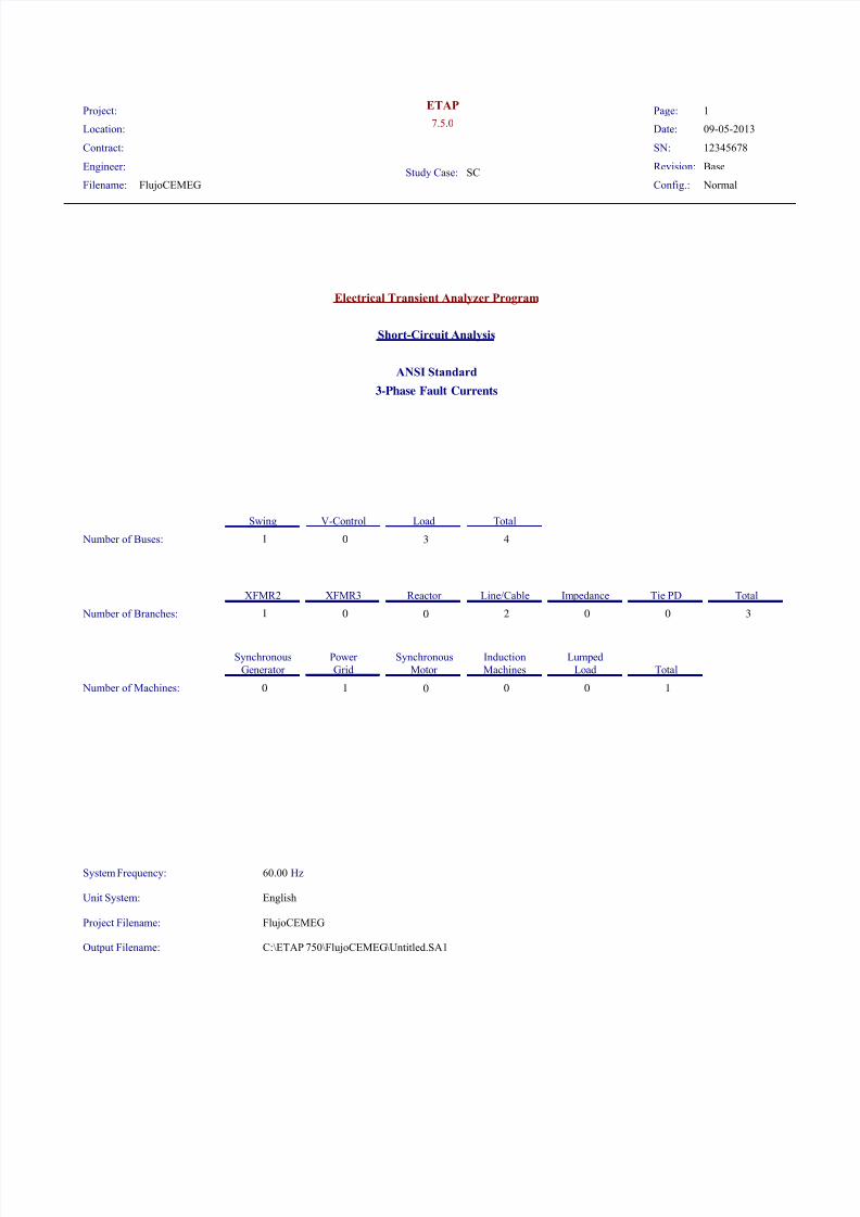
Location: Engineer: Study Case: SC 7.5.0 Page: 1 SN: 12345678 Filename: FlujoCEMEG Project: ETAP Contract: Date: 09-05-2013 Revision: Base Config.: Normal Electrical Transient Analyzer Program Short-Circuit Analysis ANSI Standard 3-Phase Fault Currents Number of Buses: Number of Branches: Number of Machines: 3 1 0 0 0 0 2 4 0 0 3 1 0 0 0 1 1 Swing V-Control Total Load XFMR2 Total Tie PD Im pedance Line/Cable Reactor XFMR3 Synchronous Generator Total Lumped Load Induction Machines Synchronous Motor Power Grid Unit System: Project Filename: Output Filename: System Frequency: 60.00 Hz English FlujoCEMEG C:\ETAP 750\FlujoCEMEG\Untitled.SA1
-
Upload
juanes-cevallos -
Category
Documents
-
view
213 -
download
0
Transcript of Reporte Cortos 1 - Completo
7/30/2019 Reporte Cortos 1 - Completo
http://slidepdf.com/reader/full/reporte-cortos-1-completo 1/10
Location:
Engineer:Study Case: SC
7.5.0Page: 1
SN: 12345678
Filename: FlujoCEMEG
Project: ETAP
Contract:
Date: 09-05-2013
Revision: Base
Config.: Normal
Electrical Transient Analyzer Program
Short-Circuit Analysis
ANSI Standard
3-Phase Fault Currents
Number of Buses:
Number of Branches:
Number of Machines:
3
1
0
0
0
0
2
4
0
0
3
1
0
0
0
1
1
Swing V-Control TotalLoad
XFMR2 TotalTie PDIm pedanceLine/CableReactor XFMR3
Synchronous
Generator Total
Lumped
Load
Induction
Machines
Synchronous
Motor
Power
Grid
Unit System:
Project Filename:
Output Filename:
System Frequency: 60.00 Hz
English
FlujoCEMEG
C:\ETAP 750\FlujoCEMEG\Untitled.SA1

7/30/2019 Reporte Cortos 1 - Completo
http://slidepdf.com/reader/full/reporte-cortos-1-completo 2/10
Location:
Engineer:Study Case: SC
7.5.0Page: 2
SN: 12345678
Filename: FlujoCEMEG
Project: ETAP
Contract:
Date: 09-05-2013
Revision: Base
Config.: Normal
Adjustments
Transformer Impedance:
Reactor Impedance:
Tolerance
Overload Heater Resistance:
Transmission Line Length:
Cable Length:
Temperature Correction
Transmission Line Resistance:
Cable Resistance:
Percent
Degree C
Individual
/Global
Individual
/Global
Individual
Individual
Individual
Individual
Apply
Adjustments
Apply
Adjustments
Yes
Yes
No
No
No
Yes
Yes

7/30/2019 Reporte Cortos 1 - Completo
http://slidepdf.com/reader/full/reporte-cortos-1-completo 3/10
Location:
Engineer:Study Case: SC
7.5.0Page: 3
SN: 12345678
Filename: FlujoCEMEG
Project: ETAP
Contract:
Date: 09-05-2013
Revision: Base
Config.: Normal
Bus Input Data
ID Type
Bus
Sub-sys
Initial Voltage
%Mag. Ang.Base kV Nom. kV
0.4920.480LoadBarra 0,48 kV 1 0.00100.00
0.4920.480LoadBarra 3 1 0.00100.00
13.80013.800LoadBarra 13,8 kV 1 0.00100.00
13.80013.800SWNGBARRA SWG 1 0.00100.00
4 Buses Total
All voltages reported by ETAP are in % of bus Nominal kV.
Base kV values of buses are calculated and used internally by ETAP.

7/30/2019 Reporte Cortos 1 - Completo
http://slidepdf.com/reader/full/reporte-cortos-1-completo 4/10
Location:
Engineer:Study Case: SC
7.5.0Page: 4
SN: 12345678
Filename: FlujoCEMEG
Project: ETAP
Contract:
Date: 09-05-2013
Revision: Base
Config.: Normal
Line/Cable Input Data
ID Library Size #/Phase T (°C) R
Line/Cable
Ohms or Siemens/1000 ft per Conductor (Cable) or per Phase (Line)
Adj. (ft) % Tol.
Length
YX
Cable33 0,6NCUN3 2 65.6 1 0.20200750 0.00000000.03900
DP-440001P 0,6MCUN3 2/0 65.6 1 0.10200750 0.00000000.04070
Line / Cable resistances are listed at the specified temperatures.

7/30/2019 Reporte Cortos 1 - Completo
http://slidepdf.com/reader/full/reporte-cortos-1-completo 5/10
Location:
Engineer:Study Case: SC
7.5.0Page: 5
SN: 12345678
Filename: FlujoCEMEG
Project: ETAP
Contract:
Date: 09-05-2013
Revision: Base
Config.: Normal
2-Winding Transformer Input Data
ID MVA Prim. kV Sec. kV % Z X/R Prim. Sec.
Transformer % Tap Setting
% Tol.
Rating Z Variation
+ 5% - 5% % Z
Adjusted
XFMR - 440001 0.150 13.800 0.480 4.00 3.09 -2.500 00 0 0 4.0000

7/30/2019 Reporte Cortos 1 - Completo
http://slidepdf.com/reader/full/reporte-cortos-1-completo 6/10
Location:
Engineer:Study Case: SC
7.5.0Page: 6
SN: 12345678
Filename: FlujoCEMEG
Project: ETAP
Contract:
Date: 09-05-2013
Revision: Base
Config.: Normal
Branch Connections
ID From Bus To Bus R X ZType
CKT/Branch % Impedance, Pos. Seq., 100 MVAbConnected Bus ID
Y
XFMR - 440001 Barra 13,8 kV 780.53 2411.85 2535.00Barra 0,48 kV2W XFMR
Cable33 BARRA SWG 0.70 0.13 0.71Barra 13,8 kVCable
DP-440001P Barra 0,48 kV 276.15 110.19 297.32Barra 3Cable

7/30/2019 Reporte Cortos 1 - Completo
http://slidepdf.com/reader/full/reporte-cortos-1-completo 7/10
Location:
Engineer:Study Case: SC
7.5.0Page: 7
SN: 12345678
Filename: FlujoCEMEG
Project: ETAP
Contract:
Date: 09-05-2013
Revision: Base
Config.: Normal
Power Grid Input Data
ID ID MVASC kV R X
Rating
X/R
100 MVA Base% Impedance
Power Grid Connected Bus
U1 13.800 205.169909.4027048.689BARRA SWG 21.82
Total Connected Power Grids (= 1 ): 48.689 MVA

7/30/2019 Reporte Cortos 1 - Completo
http://slidepdf.com/reader/full/reporte-cortos-1-completo 8/10
Location:
Engineer:Study Case: SC
7.5.0Page: 8
SN: 12345678
Filename: FlujoCEMEG
Project: ETAP
Contract:
Date: 09-05-2013
Revision: Base
Config.: Normal
SHORT-CIRCUIT REPORT
3-phase fault at bus: Barra 3
Prefault voltage = 0.480 = 100.00 % of nominal bus kV ( 0.480 kV)
= 97.50 % of base ( 0.492 kV)
ID Magnitude/RealRealFrom BusID ImaginaryFrom Bus To Bus % V kA kA Imag. kA Symm.
Contribution 1/2 Cycle
Total 3.9042.61.4220.00Barra 3 -3.636
Barra 3 3.9042.61.42210.15Barra 0,48 kV -3.636
NACD Ratio = 1.00
# Indicates a fault current contribution from a three-winding transformer
* Indicates a fault current through a tie circuit breaker
If faulted bus is involved in loops formed by protection devices, the short-circuit contributions through these PDs will not be reported.

7/30/2019 Reporte Cortos 1 - Completo
http://slidepdf.com/reader/full/reporte-cortos-1-completo 9/10
Location:
Engineer:Study Case: SC
7.5.0Page: 9
SN: 12345678
Filename: FlujoCEMEG
Project: ETAP
Contract:
Date: 09-05-2013
Revision: Base
Config.: Normal
Momentary Duty Summary Report
3-Phase Fault Currents: (Prefault Voltage = 100 % of the Bus Nominal Voltage)
ID kA PeakkA rmskA rmskA Peak kA rmsM.F.RatiokA rmsTypeIDkV
Symm. X/R Asymm. Asymm. Symm. Asymm. Asymm.
Momentary DutyDeviceBus Device Capability
22.0000.0007.1384.2261.0822.63.904Barra 30.480Barra 3 *Panelboard
Method: IEEE - X/R is calculated from separate R & X networks.
* Indicates a device with momentary duty exceeding the device capability
Protective device duty is calculated based on total fault current.
The multiplication factors for high voltage circuit-breaker and high voltage bus momentary duty (asymmetrical and crest values) are calculated based on system X/R.

7/30/2019 Reporte Cortos 1 - Completo
http://slidepdf.com/reader/full/reporte-cortos-1-completo 10/10