set de instrucciones primera parte de atmel
26
SET DE INSTRUCCIONES ATMEL OPERACIONES ARITMETICAS Y LOGICAS José Arturo Álvarez Mtz. Universidad Autónoma de Querétaro Facultad de Informática MAESTRÍA EN SOFTWARE EMBEBIDO
-
Upload
tecnomaquinados-de-queretaro -
Category
Engineering
-
view
23 -
download
0
Transcript of set de instrucciones primera parte de atmel

SET DE INSTRUCCIONES ATMEL OPERACIONES ARITMETICAS Y LOGICAS
José Arturo Álvarez Mtz.Universidad Autónoma de Querétaro
Facultad de InformáticaMAESTRÍA EN SOFTWARE EMBEBIDO
AVR Registers
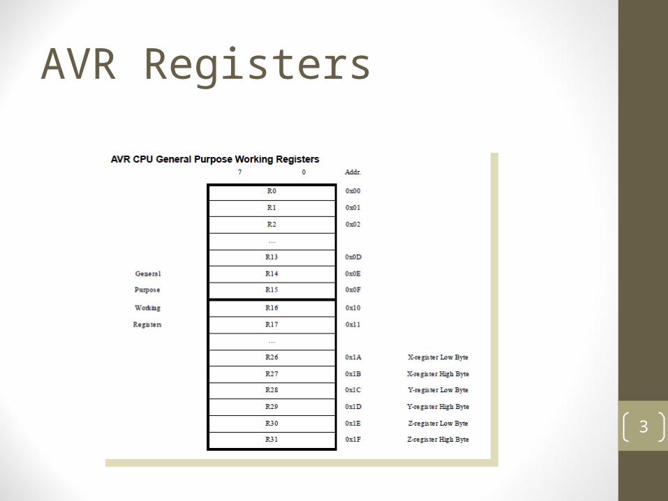
• General purpose registers• 32 8-bit registers, R0 ~ R31 or r0 ~ r31• Can be further divided into two groups
• First half group: R0 ~ R15 and second half group: R16~ R31
• Some instructions work only on the second half group R16~R31
▪ E.g. ldi rd, #number ;rd R16~R31
2
AVR Registers
3
AVR Registers
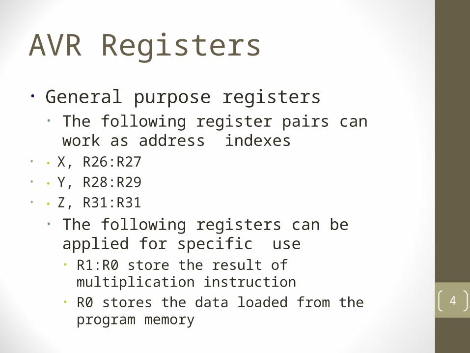
• General purpose registers• The following register pairs can work as
address indexes• • X, R26:R27• • Y, R28:R29• • Z, R31:R31
• The following registers can be applied for specific use• R1:R0 store the result of multiplication instruction• R0 stores the data loaded from the program
memory4
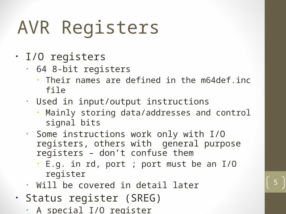
AVR Registers• I/O registers
• 64 8-bit registers• Their names are defined in the m64def.inc file
• Used in input/output instructions• Mainly storing data/addresses and control signal bits
• Some instructions work only with I/O registers, others with general purpose registers – don’t confuse them• E.g. in rd, port ; port must be an I/O register
• Will be covered in detail later• Status register (SREG)
• A special I/O register5
6
The Status Register in AVR• The Status Register (SREG) contains
information about the result of the most recently executed arithmetic instruction. This information can be used for altering program flow in order to perform conditional operations.
• SREG is updated after any of ALU operations by hardware.
• SREG is not automatically stored when entering an interrupt routine and restored when returning from an interrupt. This must be handled by software.• Using in/out instruction to store/restore SREG

The Status Register in AVR (cont.)
I T H S V N Z C
Bit 7 6 5 4 3 2 1 0
• Bit 7 – I: Global Interrupt Enable• Used to enable and disable interrupts.• 1: enabled. 0: disabled.• The I-bit is cleared by hardware after an interrupt
has occurred, and is set by the RETI instruction to enable subsequent interrupts.
The Status Register in AVR (cont.)
I T H S V N Z C
Bit 7 6 5 4 3 2 1 0
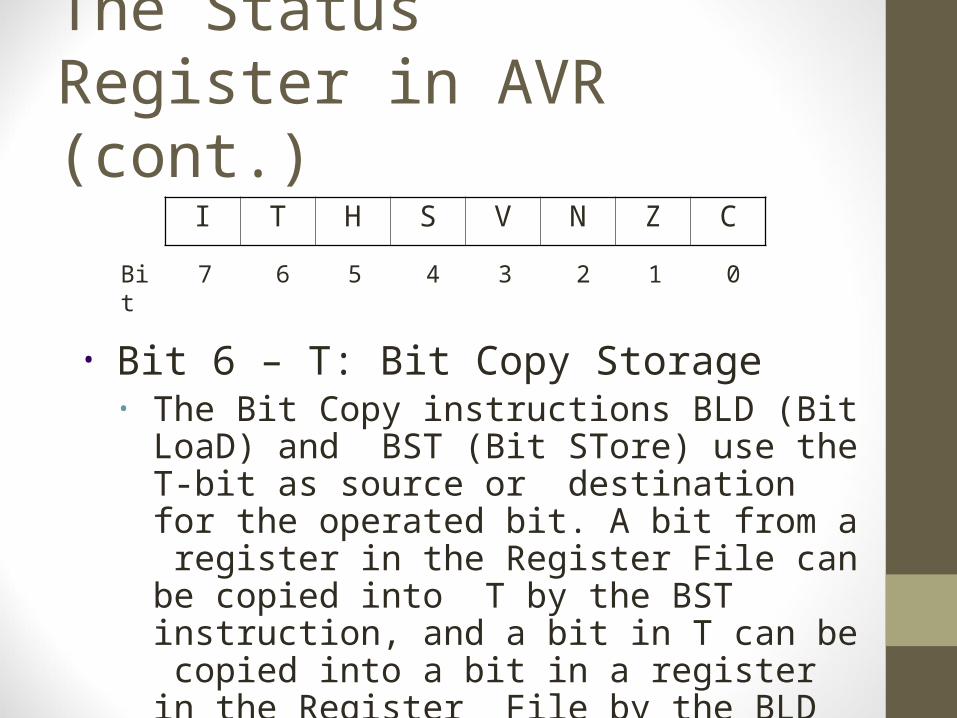
• Bit 6 – T: Bit Copy Storage• The Bit Copy instructions BLD (Bit LoaD) and
BST (Bit STore) use the T-bit as source or destination for the operated bit. A bit from a register in the Register File can be copied into T by the BST instruction, and a bit in T can be copied into a bit in a register in the Register File by the BLD instruction.
The Status Register in AVR (cont.)
I T H S V N Z C
Bit 7 6 5 4 3 2 1 0
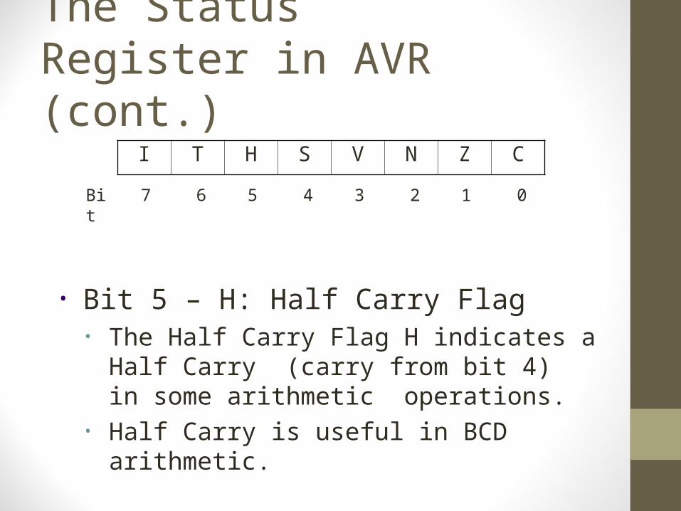
• Bit 5 – H: Half Carry Flag• The Half Carry Flag H indicates a Half Carry
(carry from bit 4) in some arithmetic operations.
• Half Carry is useful in BCD arithmetic.

The Status Register in AVR (cont.)
I T H S V N Z C
Bit 7 6 5 4 3 2 1 0
• Bit 4 – S: Sign Bit• Exclusive OR between the Negative Flag N and the
Two’s Complement Overflow Flag V ( S = N V).• Bit 3 – V: Two’s Complement Overflow Flag
• The Two’s Complement Overflow Flag V supports two’s complement arithmetic.
The Status Register in AVR (cont.)
I T H S V N Z C
Bit 7 6 5 4 3 2 1 0
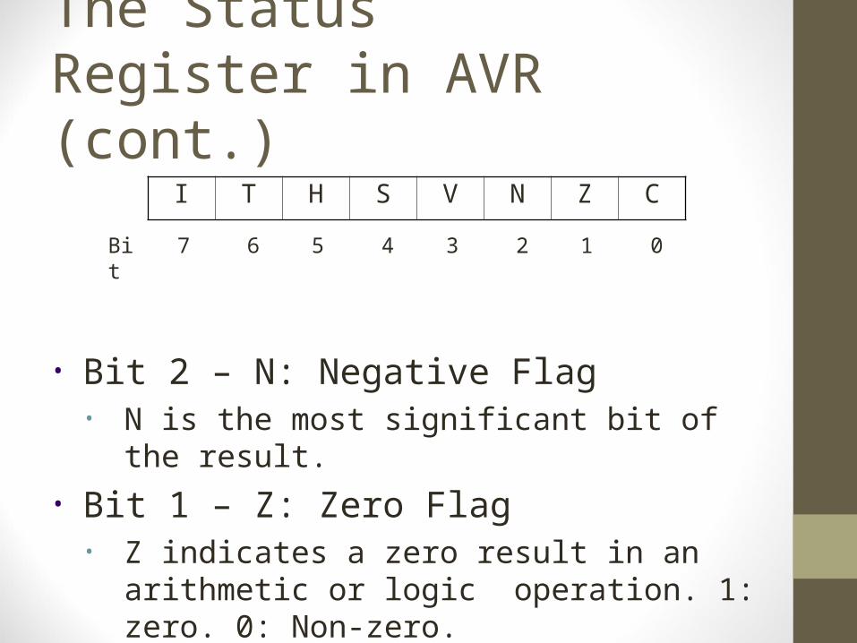
• Bit 2 – N: Negative Flag• N is the most significant bit of the result.
• Bit 1 – Z: Zero Flag• Z indicates a zero result in an arithmetic or logic
operation. 1: zero. 0: Non-zero.
The Status Register in AVR (cont.)
I T H S V N Z C
Bit 7 6 5 4 3 2 1 0
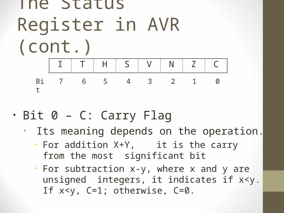
• Bit 0 – C: Carry Flag• Its meaning depends on the operation.
• For addition X+Y, it is the carry from the most significant bit
• For subtraction x-y, where x and y are unsigned integers, it indicates if x<y. If x<y, C=1; otherwise, C=0.

15
Data Memory Space• Covers
• Register file• I.e. registers in the
register file also have memory address
• I/O registers• I.e. I/O registers have two
versions of addresses▪ I/O addresses▪ Memory addresses
• SRAM data memory• The highest memory
location is defined asRAMEND
32 General purpose Working Registers
0x0000
64 Input/Output Registers
Internal SRAM (128~4K bytes)
External SRAM
0x1F0x20
End Address
Data Memory
0x5F0x60
8 bits

16
Program Memory SpaceProgram Memory
• Covers• 16 bit Flash Memory
• Read only▪ Instructions are retained
when power off• Can be accessed with
special instructions• LPM• SPM
0x0000
Program Flash Memory
(1K bytes~128K bytes)
16 Bits
End Address

17
EEPROM Memory Space• Covers
• 8-bit EEPROM memory• Use to permanently
store large set of data• Can be accessed
using load and store instructions with special control bit settings
• Not covered in this course
Data EEPROM Memory0x0000
EEPROM Memory (64~4K bytes)
8 bits
End address

18
AVR Instruction Format• For AVR, almost all instructions are 16 bits
long• add Rd, Rr• sub Rd, Rr• mul Rd, Rr• brge k
• Few instructions are 32 bits long• lds Rd, k ( 0 k 65535 )
• loads 1 byte from the SRAM to a register.

AL Instructions
Week4
17
• Arithmetic• addition
• E.g. ADD Rd, Rr• Subtraction
• E.g. SUB Rd, Rr• Increment/decrement
• E.g INC Rd• Multiplication
• E.g. MUL Rd, Rr
• Logic• E.g. AND Rd, Rr
• Shift• E.g. LSL Rd
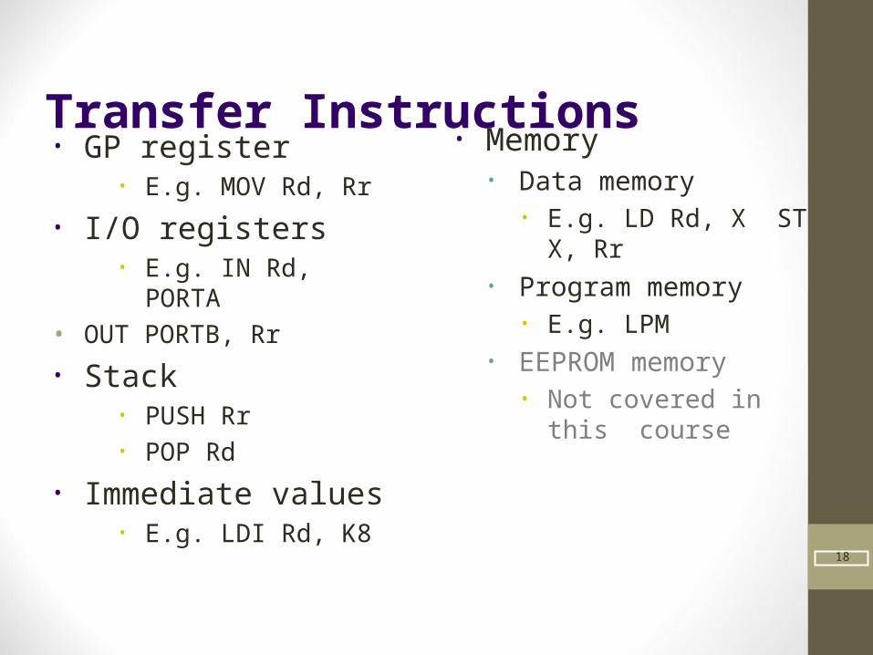
Transfer Instructions
Week4
18
• GP register• E.g. MOV Rd, Rr
• I/O registers• E.g. IN Rd, PORTA
• OUT PORTB, Rr• Stack
• PUSH Rr• POP Rd
• Immediate values• E.g. LDI Rd, K8
• Memory• Data memory
• E.g. LD Rd, X ST X, Rr
• Program memory• E.g. LPM
• EEPROM memory• Not covered in this
course
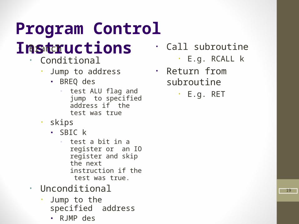
Program Control Instructions
Week4
19
• Branch• Conditional
• Jump to address▪ BREQ des
▪ test ALU flag and jump to specified address if the test was true
• skips▪ SBIC k
▪ test a bit in a register or an IO register and skip the next instruction if the test was true.
• Unconditional• Jump to the specified
address▪ RJMP des
• Call subroutine• E.g. RCALL k
• Return from subroutine• E.g. RET
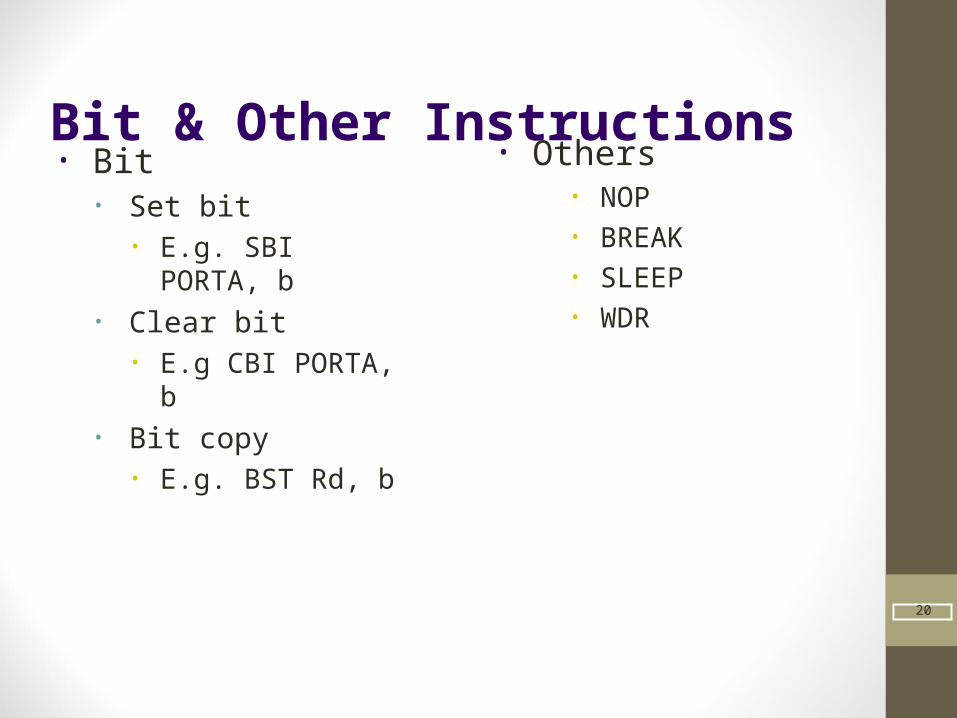
Bit & Other Instructions
Week4
20
• Bit• Set bit
• E.g. SBI PORTA, b• Clear bit
• E.g CBI PORTA, b• Bit copy
• E.g. BST Rd, b
• Others• NOP• BREAK• SLEEP• WDR

Juego de instrucciones: Aritméticas y lógicas
-Los operandos sólo pueden ser registros o constantes.-Suma aritmética
- Sin acarreo- Con acarreo- Suma con registros 16 bits y dato
inmediato
21
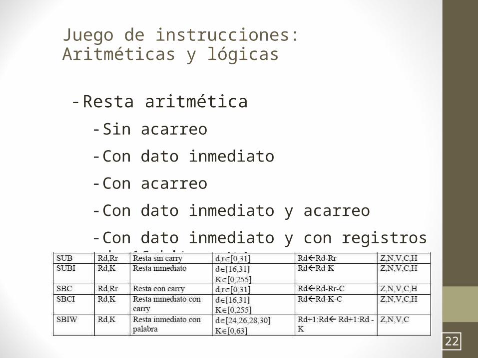
Juego de instrucciones: Aritméticas y lógicas
- Resta aritmética- Sin acarreo- Con dato inmediato- Con acarreo- Con dato inmediato y acarreo- Con dato inmediato y con registros de
16 bits.
22
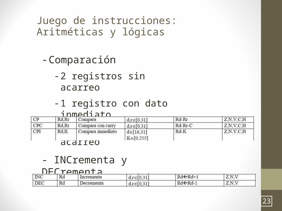
Juego de instrucciones: Aritméticas y lógicas
- Comparación- 2 registros sin acarreo- 1 registro con dato
inmediato- 2 registros con acarreo
- INCrementa y DECrementa
23
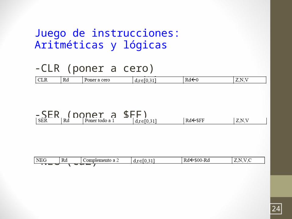
Juego de instrucciones: Aritméticas y lógicas
-CLR (poner a cero)
-SER (poner a $FF)
-NEG (Ca2)
24
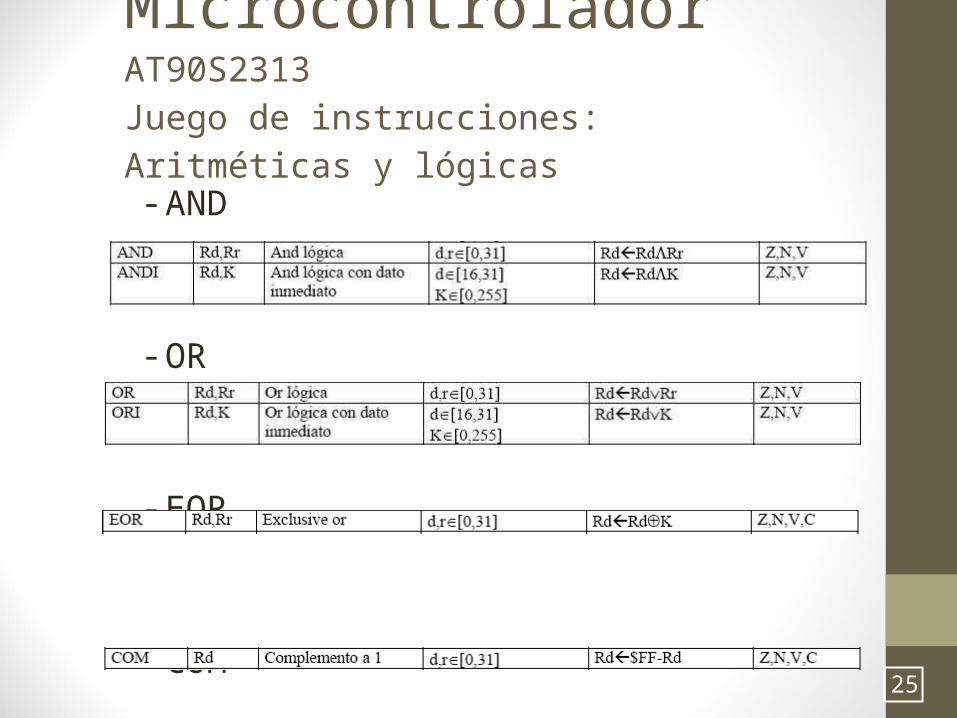
Microcontrolador AT90S2313
Juego de instrucciones: Aritméticas y lógicas
- AND
- OR
- EOR
- COM 25

Bibliografía • http://www.atmel.com/images/Atmel-0856-AVR-Instruction-Set-Manual.pdf
• http://www.cse.unsw.edu.au/~cs2121/LectureNotes/week4_notes.pdf
• https://www.dte.us.es/tec_inf/itig/microele/docu/curso0506/tema4/tema4_parte1_micro_0506.pdf
26