Shubham pal (seminar presentation)
23
Seminar topic: Ground Improvement Techniques Submitted by: YASHAVANT KUMAR SHUBHAM PAL 1303200125 1303200103 CVIL DEPARTMENT 1
-
Upload
shubham-pal -
Category
Engineering
-
view
185 -
download
3
Transcript of Shubham pal (seminar presentation)

1 Seminar topic: Ground Improvement
Techniques
Submitted by: YASHAVANT KUMAR SHUBHAM PAL1303200125 1303200103
CVIL DEPARTMENT
2 INTRODUCTION :
FOUNDATION SOIL
(i) If shallow soil is good we provide shallow foundation
(ii) If deep soil is good we provide deep foundation
“BUT IF DEEP SOIL IS ALSO NOT GOOD’’
“GROUND IMPROVEMENT TECHNIQUES”
3 GROUND IMPROVEMENT
TECHNIQUES
OBJECTIVE
(i) To increase shear strength
( it increases bearing capacity )
(ii) To decrease compressibility
( it decreases the settlement)

4
GROUND IMPROVEMENT TECHNIQUES
For Cohesive soil For Non cohesive Soil (i)Precompression (i)Vibrofloatation (ii)Sand drains (ii)Terra probe (iii)Wick drains (iii)Dynamic impaction (iv)stone columns (iv)Compaction by blasts (v)Compaction piles

5 IMPROVEMENT OF COHESSIVE SOILS :
a. Pre-compression b. Sand Drainsc. Wick Drainsd. Stone Columns
6PRE-COMPRESSION
Temporary preloading the ground before construction to cause consolidation.
Height of surcharge is 3 to 10 m. Kept for long time and then removed.

7PRINCIPLE1.AB indicates decrease in void ratio during in tial loading.2.BEC shows increase in void ratio during unloading.3.CFD indicates decrease in void ratio when soil is reloaded.\4.Therefore decrease in void ratio during reloading is much lesser than that in initial loading5. It means bearing capacity of soil has improved. It behaves as over consolidated soil.
8Advantages and Disadvantages
Advantage simple and convinient Inexpensive Ensures uniformity
Disadvantage Time of consolidation is quiet long Method is expensive if surcharge material is not available near to site Method requires large area
SAND DRAINS
Sand drains are installed under a surcharge load to accelerate the drainage of impervious soils and thus speed up consolidation
These drains provide a shorter path for the water to flow through to get away from the soil
Time to drain clay layers can be reduced from years to a couple of months
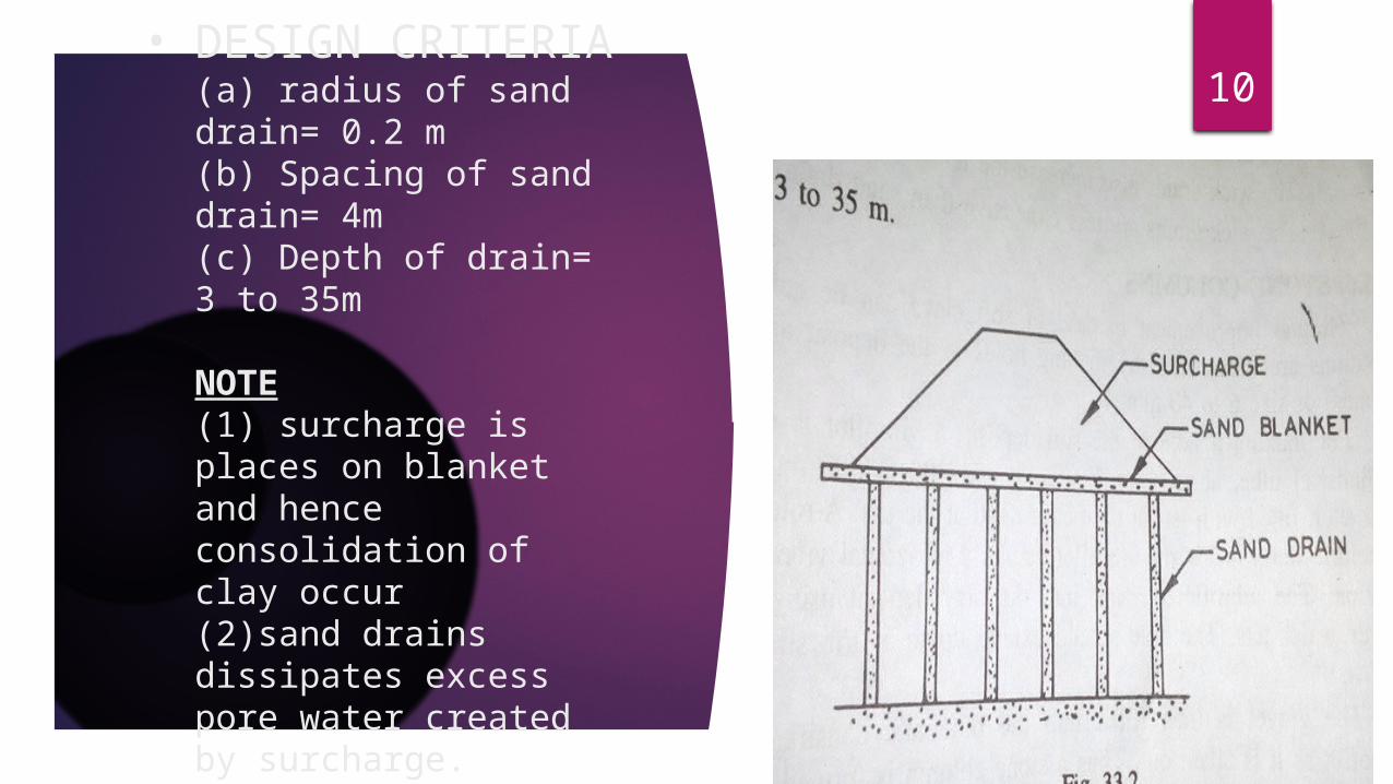
10• DESIGN CRITERIA(a) radius of sand drain= 0.2 m(b) Spacing of sand drain= 4m(c) Depth of drain= 3 to 35m
NOTE(1) surcharge is places on blanket and hence consolidation of clay occur(2)sand drains dissipates excess pore water created by surcharge.
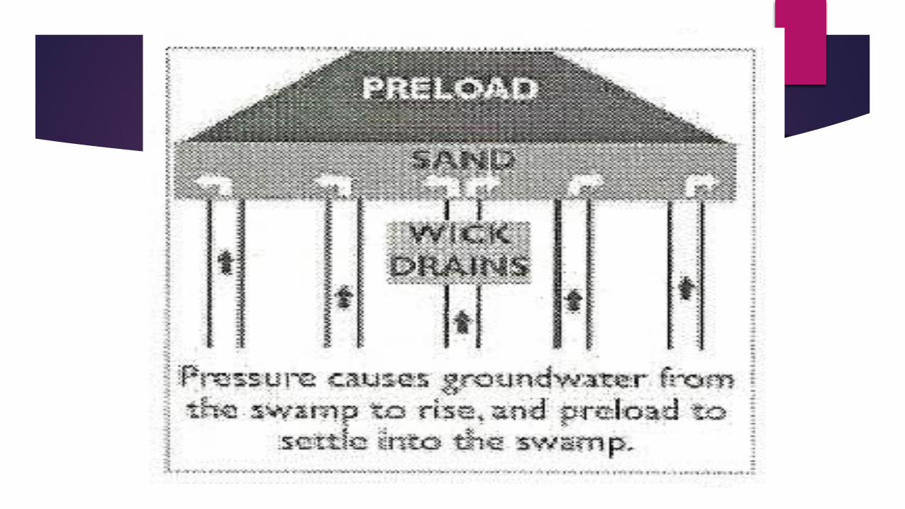
Wick Drains
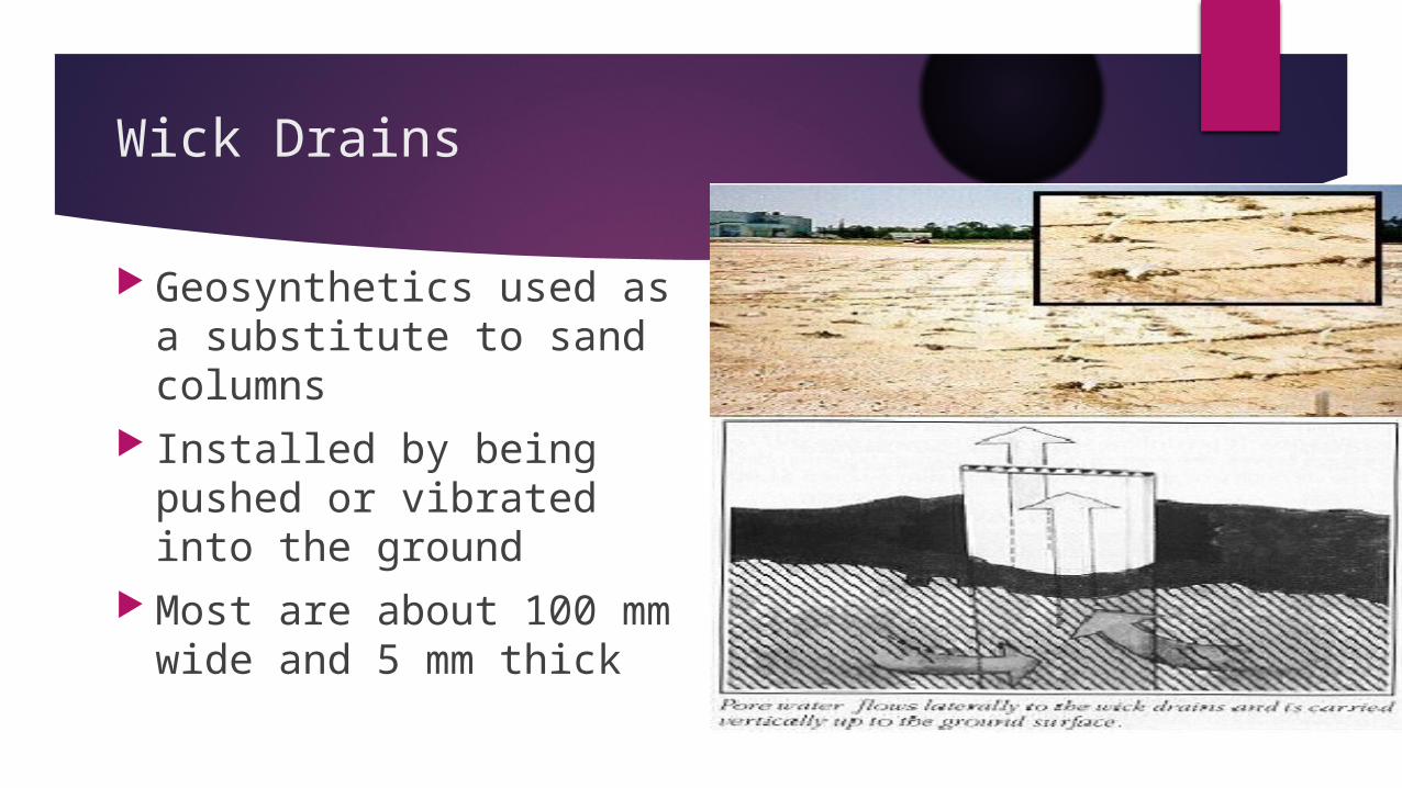
Geosynthetics used as a substitute to sand columns
Installed by being pushed or vibrated into the ground
Most are about 100 mm wide and 5 mm thick
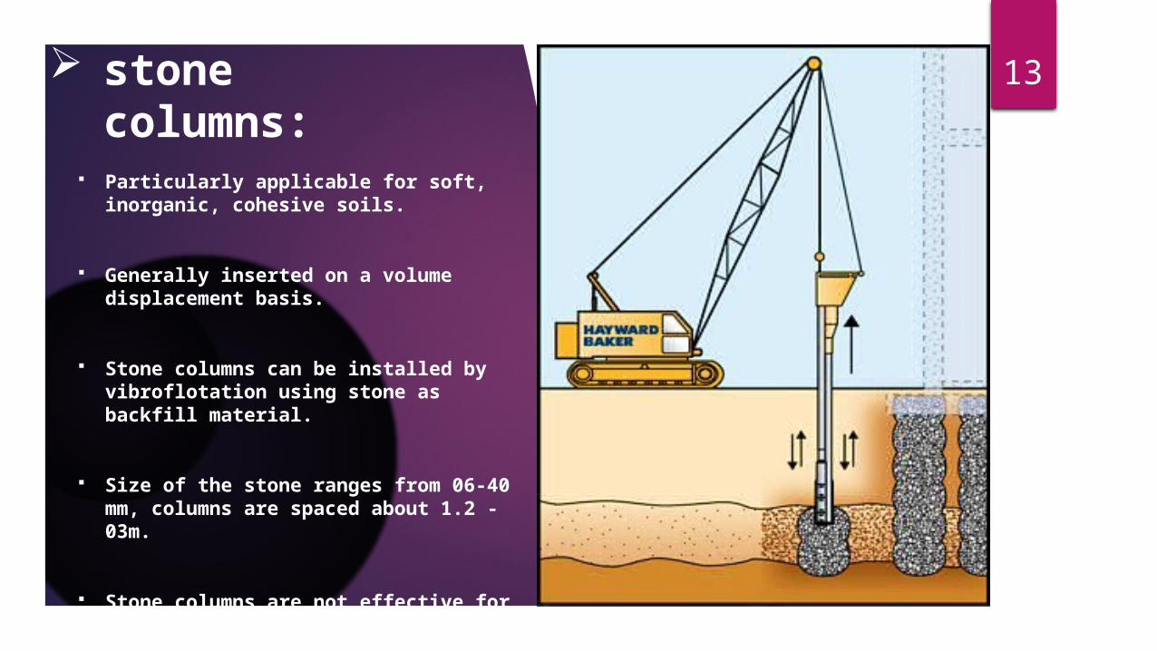
13 stone columns: Click icon to add picture
Particularly applicable for soft, inorganic, cohesive soils.
Generally inserted on a volume displacement basis.
Stone columns can be installed by vibroflotation using stone as backfill material.
Size of the stone ranges from 06-40 mm, columns are spaced about 1.2 -03m.
Stone columns are not effective for thick deposits of organic clays and silts.

14 IMPROVEMENT OF
COHESIONLESS SOILS:
i. Vibroflotation.
ii. Terra probe.
iii. Dynamic Impaction
iv. Compaction by blasts
v. Compaction piles

15
Vibroflotation:Click icon to add picture
Vibroflotation is a technique
for in situ densification of
cohesionless soils. It was
developed in Germany in the
1930s.
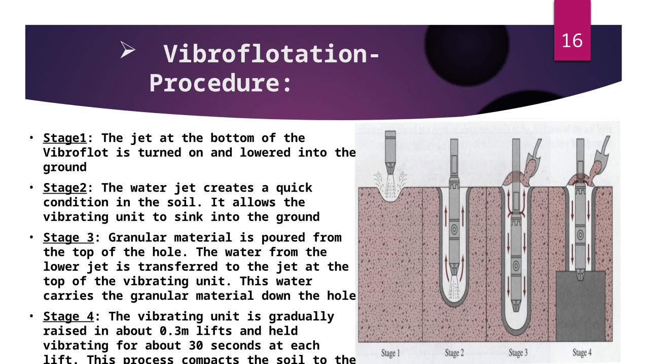
16 Vibroflotation-Procedure:
• Stage1: The jet at the bottom of the Vibroflot is turned on and lowered into the ground
• Stage2: The water jet creates a quick condition in the soil. It allows the vibrating unit to sink into the ground
• Stage 3: Granular material is poured from the top of the hole. The water from the lower jet is transferred to the jet at the top of the vibrating unit. This water carries the granular material down the hole
• Stage 4: The vibrating unit is gradually raised in about 0.3m lifts and held vibrating for about 30 seconds at each lift. This process compacts the soil to the desired unit weight.
17 TERRA PROBE
1. Like vibroflotation , consist of open ended pipe , dia 75 cm & vibratory pile driver at its bottom.
2. Vibratory pile driver when activated gives vertical vibration to the terra probe.
3. Upto desired depth , terra probe is gradually raised upward while vibratory pile continues to operate.
4. Spacing of soil is kept about 1.5 m. 5. Method can be used upto depth of 20 m.6. Ideal for compaction of saturated sand deposits.
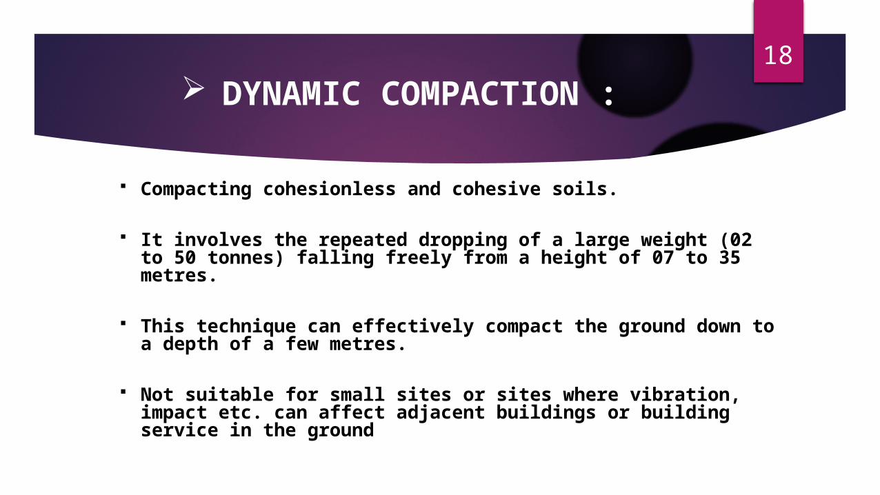
18 DYNAMIC COMPACTION :
Compacting cohesionless and cohesive soils.
It involves the repeated dropping of a large weight (02 to 50 tonnes) falling freely from a height of 07 to 35 metres.
This technique can effectively compact the ground down to a depth of a few metres.
Not suitable for small sites or sites where vibration, impact etc. can affect adjacent buildings or building service in the ground
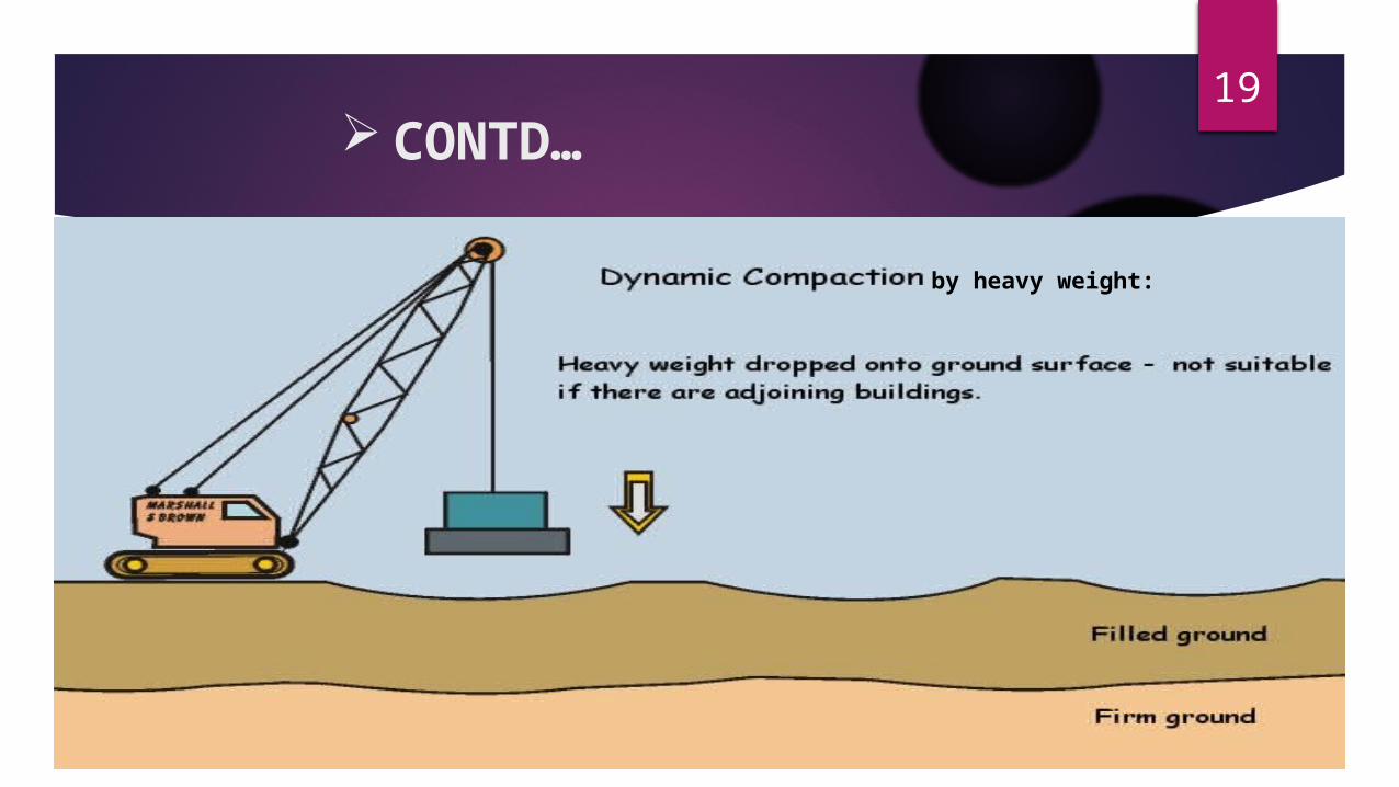
19 CONTD…
by heavy weight:
20 COMPACTION BY BLASTS
1. Buried explosive are used to densify loose sandy soils.2. Series of holes are bored and explosive are place in
them.3. The holes are filled back with soil.4. The spacing of holes is kept b/w 3 to 8 m.5. Densification by blasts is effective upto a depth of about
25 m.

21 COMPACTION PILES
1. A closed-ended , hollow tubular pile is 1st driven into the ground.
2. The loose soil surrounding pipe is compacted due to vibration.
3. Hole is backfilled with sand.4. Constructed on several location on grid pattern.5. For good result , silt content shouldn’t be greater than
15% in the soil.6. Also clay content shouldn’t be greater than 3%.
22 CONCLUSION :
Ground Improvement techniques forms technically sound and cost effective solution where the sub soils are weak and needs to be treated to enable the intended construction.
Its applicability has been proven for a wide range of structures such as roads, runways, ports, power plants, railways, dams, slope stabilisation, excavations, tunnelling and other infrastructure facilities.
These techniques have been used all over the world for a wide range of soils starting from loose sands, silts, marine clays to weak rocks.
REFERENCE Soil mechanics and Foundation engineering by Dr. R.L Arora

23