
SISTEMAS DE ANCLAJE INOXIDABLE PARA … · principe mécanique Accrochage á montant ou aiguille á...
24
SISTEMAS DE ANCLAJE INOXIDABLE PARA FACHADAS
-
Upload
duongthien -
Category
Documents
-
view
213 -
download
0
Transcript of SISTEMAS DE ANCLAJE INOXIDABLE PARA … · principe mécanique Accrochage á montant ou aiguille á...
1
SISTEMAS DE ANCLAJE INOXIDABLE PARA FACHADAS

INOXMARK, nació en el año 1998. La juventud de la empresa,
la calidad del producto y el gusto por las cosas bien hechas, han
fructificado en los sistemas de anclajes INOXMARK, que permiten
llegar hasta donde la imaginación del proyectista desea, en el anclaje
de las piedras y otros materiales en las fachadas ventiladas.
Nuestros métodos de fabricación establecen un sistemático control
que comienza con la recepción de las materias primas y concluye
cuando el producto sale de la fábrica, listo para su utilización en obra.
Cada sistema de anclajes es la culminación del diseño geométrico
y el cálculo mecánico, desarrollados por nuestros especialistas
colaboradores.
El deseo permanente de mejorar, nos lleva a adaptar los productos
a la normativa europea y americana, diseñando, incluso sistemas de
ensayo específicos para nuestros productos.
Le ofrecemos anclajes de calidad, al mejor precio y en el período de
tiempo más corto posible, asesorándole, cuando sea necesario, en la
resolución de las dificultades que puedan surgir en la colocación.
Estamos a su servicio, en la seguridad de que siempre encontrará la
respuesta adecuada en cada momento.

TIPOPOSICIÓN RESPECTOAL REVESTIMIENTO
COMPORTAMIENTO MECÁNICO
CAPACIDAD DE REGULACIÓN
PROCEDIMIENTO DE FIJACIÓN AL SOPORTE
FORMA DE UNIÓN AL REVESTIMIENTO
Puntual o directo Anclaje oculto en el canto del revestimiento
Anclaje de sustentación / retención
Regulable entres dimensiones
Mediante taco de diferente naturaleza y principio mecánico
Anclaje con pasador o aguja en el canto de las piezas del revestimiento con interposición del material elástico
SUBSISTEMAS DE ANCLAJE
TYPEPOSITION WITH RESPECT TO COATING
MECHANICALCONDUCT
REGULATIONCAPACITY
PROCEDURE OF FIXING TO SUPPORT
PROCEDURE OFFIXING TO COATING
Precision or direct Concealed fixingon edge of coating
Fixings of sustinence / retention
Regulation in three dimensions
By means of different natured plug and mechanical ways
Fixing of pin on edge of coating pieces with interposition of elasticated material
SUBSYSTEMS OF FIXINGSOUS-SYSTÈMES D´ACCROCHAGE
TYPEPOSITION PAR RAPPORT AU REVÊTEMENT
FONCTIONNEMENT MÉCANIQUE
CAPACITÉ DE RÉGLAGE
PROCÉDÉ DE FIXATION AU SUPPORT
FORME D´UNION AU REVÊTEMENT
Ponctuel ou direct Ancrage caché dans la pierre du revêtement
Ancrage de soutient / retention
Reglable en trois dimensions
Au moyen d´une chevillede diffèrente nature et principe mécanique
Accrochage á montant ou aiguille á travers la pierre du revêtement avec interposition de matériel élastique
SYSTÈMES D’ANCRAGE INOX POUR FAÇADESSSTAINLESS STEEL ANCHORAGE SYSTEMS FOR FACADES
INOXMARK, born in 1998. The youth of the
company, product quality and taste for things well
done, have borne fruit in INOXMARK anchorages
systems, that can reach as far as the imagination
of the designer wants, in anchoring stones and
other materials in the ventilated facades.
Our manufacturing methods establish a systematic
control that begins with the reception of raw
materials and ends when the product leaves
the factory, ready for use on site. Each anchor
system is the culmination of geometric design
and mechanical calculation, developed by our
specialist partners.
The constant desire to improve, leads us to tailor
products to European and American regulations,
designing, including specific test systems for our
products.
We offer quality anchors, the best price and in the
shortest possible period of time, advising, when
necessary, to resolve any difficulties that may arise
in the placement.
We are at your service, safety will always find the
right answer every time.
Fruits INOXMARK, né en 1998. La jeunesse de
l’entreprise, la qualité du produit et le goût pour
les choses bien faites, ont porté dans INOXMARK
systèmes d’ancrages, qui peut atteindre aussi
loin que l’imagination du concepteur veut, dans
l’ancrage pierres et autres matériaux dans les
façades ventilées.
Nos méthodes de fabrication d’établir un contrôle
systématique qui commence par la réception
des matières premières et se termine lorsque le
produit sort de l’usine, prêt à l’emploi sur le site.
Chaque système d’ancrage est l’aboutissement de
la conception géométrique et calcul mécanique,
développé par nos partenaires spécialisés.
Le souci constant d’améliorer, nous conduit
à adapter les produits aux réglementations
européennes et américaines, la conception, y
compris les systèmes de test spécifiques pour nos
produits.
Nous offrons des ancres de qualité, le meilleur
prix et dans les plus brefs délais possibles, de
conseiller, si nécessaire, de résoudre les difficultés
qui peuvent surgir dans le placement.
Nous sommes à votre service, la sécurité
trouverez toujours la bonne réponse à chaque
fois.

7
ANCLAJEPARAPIEDRASTONE ANCHORAGEANCRAGE POUR PIERRE

8 ANCLAJE PARA PIEDRA
0-10CARGA PUNTUAL
ANCLAJE PARA PIEDRAPRECISE LOAD
CHARGE PONCTUELLE
MÓD
ULO
DE
ELAS
TICI
DAD
DIÁM
ETRO
LUZ
DE
CÁLC
ULO
CARG
A TO
TAL
COEF
ICIE
NTE
POND
ERAC
IÓN
CARG
A CÁ
LCUL
O
SECC
IÓN
MOM
ENTO
DE
INER
CIA
MÓD
ULO
RESI
STEN
TE
MOM
ENTO
FL
EXIÓ
N M
ÁXIM
A
TENS
IÓN
ÁNGU
LO
FLEC
HA D
E GI
RO
FLEC
HA
MÁX
IMA
FLEC
HA D
E CÁ
LCUL
O
ELAS
TICI
TY
MOD
ULE
DIAM
ETER
LIGH
T OF
CA
LCUL
ATIO
N
TOTA
L LO
AD
CONS
TANC
Y OF
W
EIGH
TING
LOAD
CA
LCUL
ATIO
N
SECT
ION
MOM
ENT
OF
INER
TIA
RESI
STEN
CE
MOD
ULE
MOM
ENT
OF M
AX.
FLEX
ION
TENS
ION
ANGL
E
GIRA
TORY
BO
LT
MAX
IMUM
BO
LT
CALC
ULAT
ION
BOLT
MOD
ULE
D´ÉL
ASTI
CITÉ
DIAM
ÈTRE
LUM
IÈRE
DE
CALC
UL
CHAR
GE TO
TALE
COFF
ICIE
NT D
E PO
NDÉR
ATIO
N
CHAR
GE
DE C
ALCU
L
COUP
URE
MOM
ENT
D´IN
ERTI
E
MOD
ULE
RÉSI
STAN
T
MOM
ENT
FLÉC
HISS
ANT
MAX
IMAL
E
TENS
ION
ANGL
E
FLÈC
HE D
E VI
RAGE
FLÈC
HE
MAX
IMAL
E
FLÈC
HE D
E CA
LCUL
E(N/mm2)*103 Ø (cm) L (cm) *Kg γf1 P (Kg) Ω (cm2) I2 (mm4) Wz (mm3) Mf (N cm) α (N/mm2) Radianes γ mm γmax. (mm) γcal. (mm)
200 10 4 82 1,5 123 0,7854 490,87 98,17 4.909 500 0,0038 0,15 1,400 1,250
200 10 5 65 1,5 98 0,7854 490,87 98,17 4.909 500 0,0030 0,15 1,400 1,250
200 10 6 55 1,5 82 0,7854 490,87 98,17 4.909 500 0,0025 0,15 1,400 1,250
200 10 7 47 1,5 70 0,7854 490,87 98,17 4.909 500 0,0021 0,15 1,400 1,250
200 10 8 41 1,5 61 0,7854 490,87 98,17 4.909 500 0,0019 0,15 1,400 1,250
200 10 9 34 1,5 51 0,7854 490,87 98,17 4.545 463 0,0017 0,15 1,400 1,250
200 10 10 25 1,5 37 0,7854 490,87 98,17 3.682 375 0,0015 0,15 1,400 1,250
200 10 11 18 1,5 28 0,7854 490,87 98,17 3.043 310 0,0014 0,15 1,400 1,250
200 10 12 14 1,5 21 0,7854 490,87 98,17 2.557 260 0,0013 0,15 1,400 1,250
* RESISTENCIA APROXIMADA / APROXIMATE RESISTENCE
Cuando las solicitaciones son mayores, el anclaje 0 aumenta su diámetro hasta 14 mm.
El pasador también de acero inoxidable, establece la unión entre elemento de fachada y vástago del anclaje.
La funda cilíndrica de PVC, permite un reparto uniforme de solicitaciones evitando la concentración de tensiones.
Garantía de un adecuado funcionamiento mecánico en situaciones más exigentes.
La calidad del producto, la experiencia del sector y el indispensable buen hacer de los técnicos lograrán obras singulares que permanecerán en el tiempo.
When the stresses are greater the “0” type anchoring increases its diameter fron 0 to 14 mm.
The also stainless steel cotter pin establishes union between element of the facade and the anchoring stem.
The cylindrical cover of PVC, permits a uniform distribution of stresses avoiding concentrations of tensions.
It is a guarantee of proper mechanical working order in the most demanding situations.
The product´s quality, the sector´s experience and the indispensable “Know-How” of the technicians will achieve singular works that will withstand the test of time.
SISTEMAS DE ANCLAJE INOXIDABLE PARA FACHADAS
ANCLAJE TIPO 0-100-10 TYPE ANCHORINGACCROCHAGE TYPE 0-10
Lorsque les sollicitations deviennent plus importantes le diamètre de l´accrochage 0 augmente jusqu´à 14mm.
Le montant, également en acier inoxydable, unit la façade et l´accrochage.
La gaine cylindrique en P.V.C. permet une distribution uniforme des sollicitations, évitant ainsi la concentration des tensions.
Garantie de durée et de bon fonctionnement mécanique lors des situations les plus exigentes.
La qualité du produit, notre expérience dans le secteur ainsi que l´indispensable “savoir-faire” de nos techniciens réussiront á bâtir des édifices uniques qui perdureront dans le temps.

10 ANCLAJE PARA PIEDRA
Los anclajes tipo 1 adquieren una nueva dimensión al utilizar como material base acero inoxidable de lata resistencia.
El paso de rosca 10/150 es garantía de resistencia al corte de fileteado cuando el material está adecuadamente anclado al muro soporte.
El anclaje puede ser confiado a un taco de plástico alojado en el correspondiente taladro del muro soporte.
Podría eventualmente, sustituir al anclaje tipo 0 si las solicitaciones así lo exigieran, confiando, incluso, la unión a un material de relleno o cemento.
El diámetro neto del núcleo vástago es de 8,16 mm.
Type 1 anchoring acquires a new dimension due to the utilization of high resistence stainless steel as a base material
The 10/150 thread pitch is a guarantee of resistance to the threaded cut when the material is properly fixed to the supporting wall.
The anchoring may be adjusted to a plastic plug placed in the respective supporting wall drill hole.
It could, possibly, substitute the “0” anchoring type if the stresses would demand it, eeven trusting, the union to a filling material or cement.
The net diameter of the shoot´s nucleus is 8,16 mm.
SISTEMAS DE ANCLAJE INOXIDABLE PARA FACHADAS
1CARGA PUNTUAL
ANCLAJE PARA PIEDRAPRECISE LOAD
CHARGE PONCTUELLE
MÓD
ULO
DE
ELAS
TICI
DAD
DIÁM
ETRO
LUZ
DE
CÁLC
ULO
CARG
A TO
TAL
COEF
ICIE
NTE
POND
ERAC
IÓN
CARG
A CÁ
LCUL
O
SECC
IÓN
MOM
ENTO
DE
INER
CIA
MÓD
ULO
RESI
STEN
TE
MOM
ENTO
FL
EXIÓ
N M
ÁXIM
A
TENS
IÓN
ÁNGU
LO
FLEC
HA D
E GI
RO
FLEC
HA
MÁX
IMA
FLEC
HA D
E CÁ
LCUL
O
ELAS
TICI
TY
MOD
ULE
DIAM
ETER
LIGH
T OF
CA
LCUL
ATIO
N
TOTA
L LO
AD
CONS
TANC
Y OF
W
EIGH
TING
LOAD
CA
LCUL
ATIO
N
SECT
ION
MOM
ENT
OF
INER
TIA
RESI
STEN
CE
MOD
ULE
MOM
ENT
OF M
AX.
FLEX
ION
TENS
ION
ANGL
E
GIRA
TORY
BO
LT
MAX
IMUM
BO
LT
CALC
ULAT
ION
BOLT
MOD
ULE
D´ÉL
ASTI
CITÉ
DIAM
ÈTRE
LUM
IÈRE
DE
CALC
UL
CHAR
GE TO
TALE
COFF
ICIE
NT D
E PO
NDÉR
ATIO
N
CHAR
GE
DE C
ALCU
L
COUP
URE
MOM
ENT
D´IN
ERTI
E
MOD
ULE
RÉSI
STAN
T
MOM
ENT
FLÉC
HISS
ANT
MAX
IMAL
E
TENS
ION
ANGL
E
FLÈC
HE D
E VI
RAGE
FLÈC
HE
MAX
IMAL
E
FLÈC
HE D
E CA
LCUL
E(N/mm2)*103 Ø (cm) L (cm) *Kg γf1 P (Kg) Ω (cm2) I2 (mm4) Wz (mm3) Mf (N cm) α (N/mm2) Radianes γ mm γmax. (mm) γcal. (mm)
550 8,16 4 64 1,5 97 0,5230 217,64 53,34 3867 725 0,0038 0,15 1,400 1,250
550 8,16 5 52 1,5 77 0,5230 217,64 53,34 3867 725 0,0030 0,15 1,400 1,250
550 8,16 6 43 1,5 64 0,5230 217,64 53,34 3867 725 0,0025 0,15 1,400 1,250
550 8,16 7 37 1,5 55 0,5230 217,64 53,34 3867 725 0,0021 0,15 1,400 1,250
550 8,16 8 32 1,5 48 0,5230 217,64 53,34 3867 725 0,0019 0,15 1,400 1,250
550 8,16 9 29 1,5 43 0,5230 217,64 53,34 3867 725 0,0017 0,15 1,400 1,250
550 8,16 10 26 1,5 39 0,5230 217,64 53,34 3867 725 0,0015 0,15 1,400 1,250
550 8,16 11 22 1,5 34 0,5230 217,64 53,34 3710 695 0,0014 0,15 1,400 1,250
550 8,16 12 17 1,5 26 0,5230 217,64 53,34 3117 584 0,0013 0,15 1,400 1,250
* RESISTENCIA APROXIMADA / APROXIMATE RESISTENCE
ANCLAJE TIPO 11 TYPE ANCHORINGACCROCHAGE TYPE 1
L´accrochage de type 1 dont le matériau de base est l´acier inoxydable gagne ainsi une nouvelle dimension et il en résulte une importante résistance.
Lorsque le matériel est correctement accroché au mur support, le pas de vis 10/150 garantit la résistance au découpage du filetage.
L´accrochage peut être fixé à une cheville en plastique logée à l´intérieur du trou taraudé correspondant sur le mur support.
Cette cheville pourrait éventuellement remplacer l´accrochage de type 0 si les sollicitations l´exigeaient, pouvant même être uni par un matériau de remplissage ou du ciment.
Le diamètre net du centre de l´accrochage est de 8,16 mm.

12 ANCLAJE PARA PIEDRA
Es la evolución técnica desde el anclaje tipo 1.
Cuando las condiciones de colocación puedan exigir unas mayores posibilidades de movimiento el anclaje 2 es la solución adecuada.
Posibilidades de movimiento en el eje del anclaje y en un eje perpendicular al anterior.
Cuando los materiales que conforman la fachada sean de un mayor espesor también este anclaje permite una más sencilla colocación sin necesidad de cajeados.
It is technical evolution from the type one anchoring.
When the placing conditions demand greater movement, the type 2 anchoring is the most fitting solution.
Possibility of movement in the anchoring axis as well as in an axis perpendicular to the previous one.
When the materials that constitute the facade have a greater thickness, this anchoring will also allow a more simple placing without needing for boxed-in slot.
SISTEMAS DE ANCLAJE INOXIDABLE PARA FACHADAS
2CARGA PUNTUAL
ANCLAJE PARA PIEDRAPRECISE LOAD
CHARGE PONCTUELLE
MÓD
ULO
DE
ELAS
TICI
DAD
DIÁM
ETRO
LUZ
DE
CÁLC
ULO
CARG
A TO
TAL
COEF
ICIE
NTE
POND
ERAC
IÓN
CARG
A CÁ
LCUL
O
SECC
IÓN
MOM
ENTO
DE
INER
CIA
MÓD
ULO
RESI
STEN
TE
MOM
ENTO
FL
EXIÓ
N M
ÁXIM
A
TENS
IÓN
ÁNGU
LO
FLEC
HA D
E GI
RO
FLEC
HA
MÁX
IMA
FLEC
HA D
E CÁ
LCUL
O
ELAS
TICI
TY
MOD
ULE
DIAM
ETER
LIGH
T OF
CA
LCUL
ATIO
N
TOTA
L LO
AD
CONS
TANC
Y OF
W
EIGH
TING
LOAD
CA
LCUL
ATIO
N
SECT
ION
MOM
ENT
OF
INER
TIA
RESI
STEN
CE
MOD
ULE
MOM
ENT
OF M
AX.
FLEX
ION
TENS
ION
ANGL
E
GIRA
TORY
BO
LT
MAX
IMUM
BO
LT
CALC
ULAT
ION
BOLT
MOD
ULE
D´ÉL
ASTI
CITÉ
DIAM
ÈTRE
LUM
IÈRE
DE
CALC
UL
CHAR
GE TO
TALE
COFF
ICIE
NT D
E PO
NDÉR
ATIO
N
CHAR
GE
DE C
ALCU
L
COUP
URE
MOM
ENT
D´IN
ERTI
E
MOD
ULE
RÉSI
STAN
T
MOM
ENT
FLÉC
HISS
ANT
MAX
IMAL
E
TENS
ION
ANGL
E
FLÈC
HE D
E VI
RAGE
FLÈC
HE
MAX
IMAL
E
FLÈC
HE D
E CA
LCUL
E(N/mm2)*103 Ø (cm) L (cm) *Kg γf1 P (Kg) Ω (cm2) I2 (mm4) Wz (mm3) Mf (N cm) α (N/mm2) Radianes γ mm γmax. (mm) γcal. (mm)
550 8,16 4 58 1,5 87 0,5230 217,64 53,34 3467 650 0,0050 0,20 1,400 1,200
550 8,16 5 46 1,5 69 0,5230 217,64 53,34 3467 650 0,0040 0,20 1,400 1,200
550 8,16 6 39 1,5 58 0,5230 217,64 53,34 3467 650 0,0033 0,20 1,400 1,200
550 8,16 7 33 1,5 50 0,5230 217,64 53,34 3467 650 0,0029 0,20 1,400 1,200
550 8,16 8 29 1,5 43 0,5230 217,64 53,34 3467 650 0,0025 0,20 1,400 1,200
550 8,16 9 26 1,5 39 0,5230 217,64 53,34 3467 650 0,0022 0,20 1,400 1,200
550 8,16 10 23 1,5 35 0,5230 217,64 53,34 3467 650 0,0020 0,20 1,400 1,200
550 8,16 11 21 1,5 32 0,5230 217,64 53,34 3467 650 0,0018 0,20 1,400 1,200
550 8,16 12 17 1,5 25 0,5230 217,64 53,34 2992 561 0,0017 0,20 1,400 1,200
* RESISTENCIA APROXIMADA / APROXIMATE RESISTENCE
ANCLAJE TIPO 22 TYPE ANCHORINGACCROCHAGE TYPE 2
L´évolution technique de l´accrochage du type 1 nous conduit à l´accrochage de type 2.
Au cas où des possibilités de mouvement plus grandes seraient exigées par les circonstances de l´installation, l´accrochage de type 2 est la bonne solution.
En effet, il y a possibilité de mouvement sur l´axe de l´accrochage et sur l´axe qui est perpendiculaire à celui-ci.
Lorsque l´épaisseur de matériaux constituants de la façade est plus grand, cet accrochage permet une installation plus simple sans l´utilisation d´emboîtements.
14 ANCLAJE PARA PIEDRA
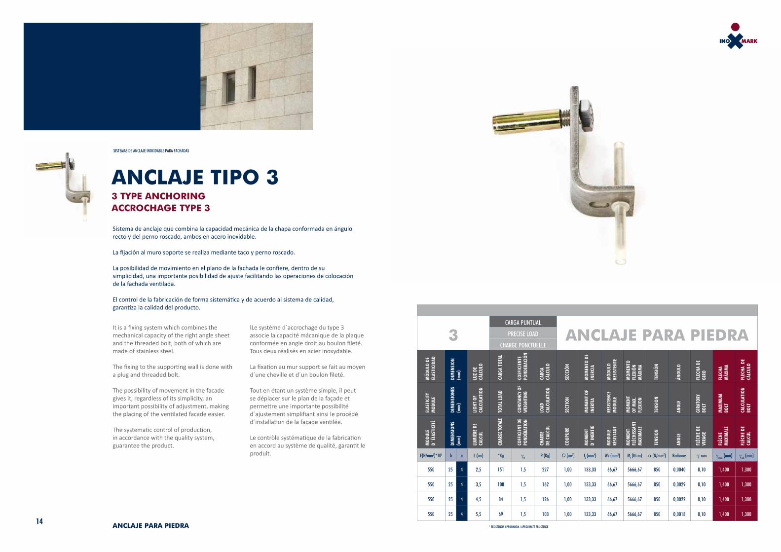
Sistema de anclaje que combina la capacidad mecánica de la chapa conformada en ángulo recto y del perno roscado, ambos en acero inoxidable.
La fijación al muro soporte se realiza mediante taco y perno roscado.
La posibilidad de movimiento en el plano de la fachada le confiere, dentro de su simplicidad, una importante posibilidad de ajuste facilitando las operaciones de colocación de la fachada ventilada.
El control de la fabricación de forma sistemática y de acuerdo al sistema de calidad, garantiza la calidad del producto.
It is a fixing system which combines the mechanical capacity of the right angle sheet and the threaded bolt, both of which are made of stainless steel.
The fixing to the supporting wall is done with a plug and threaded bolt.
The possibility of movement in the facade gives it, regardless of its simplicity, an important possibility of adjustment, making the placing of the ventilated facade easier.
The systematic control of production, in accordance with the quality system, guarantee the product.
SISTEMAS DE ANCLAJE INOXIDABLE PARA FACHADAS
3CARGA PUNTUAL
ANCLAJE PARA PIEDRAPRECISE LOAD
CHARGE PONCTUELLE
MÓD
ULO
DE
ELAS
TICI
DAD
DIM
ENSI
ON
(mm
)
LUZ
DE
CÁLC
ULO
CARG
A TO
TAL
COEF
ICIE
NTE
POND
ERAC
IÓN
CARG
A CÁ
LCUL
O
SECC
IÓN
MOM
ENTO
DE
INER
CIA
MÓD
ULO
RESI
STEN
TE
MOM
ENTO
FL
EXIÓ
N M
ÁXIM
A
TENS
IÓN
ÁNGU
LO
FLEC
HA D
E GI
RO
FLEC
HA
MÁX
IMA
FLEC
HA D
E CÁ
LCUL
O
ELAS
TICI
TY
MOD
ULE
DIM
ENSI
ONES
(mm
)
LIGH
T OF
CA
LCUL
ATIO
N
TOTA
L LO
AD
CONS
TANC
Y OF
W
EIGH
TING
LOAD
CA
LCUL
ATIO
N
SECT
ION
MOM
ENT
OF
INER
TIA
RESI
STEN
CE
MOD
ULE
MOM
ENT
OF M
AX.
FLEX
ION
TENS
ION
ANGL
E
GIRA
TORY
BO
LT
MAX
IMUM
BO
LT
CALC
ULAT
ION
BOLT
MOD
ULE
D´ÉL
ASTI
CITÉ
DIM
ENSI
ONS
(mm
)
LUM
IÈRE
DE
CALC
UL
CHAR
GE TO
TALE
COFF
ICIE
NT D
E PO
NDÉR
ATIO
N
CHAR
GE
DE C
ALCU
L
COUP
URE
MOM
ENT
D´IN
ERTI
E
MOD
ULE
RÉSI
STAN
T
MOM
ENT
FLÉC
HISS
ANT
MAX
IMAL
E
TENS
ION
ANGL
E
FLÈC
HE D
E VI
RAGE
FLÈC
HE
MAX
IMAL
E
FLÈC
HE D
E CA
LCUL
E(N/mm2)*103 b n L (cm) *Kg γf1 P (Kg) Ω (cm2) I2 (mm4) Wz (mm3) Mf (N cm) α (N/mm2) Radianes γ mm γmax. (mm) γcal. (mm)
550 25 4 2,5 151 1,5 227 1,00 133,33 66,67 5666,67 850 0,0040 0,10 1,400 1,300
550 25 4 3,5 108 1,5 162 1,00 133,33 66,67 5666,67 850 0,0029 0,10 1,400 1,300
550 25 4 4,5 84 1,5 126 1,00 133,33 66,67 5666,67 850 0,0022 0,10 1,400 1,300
550 25 4 5,5 69 1,5 103 1,00 133,33 66,67 5666,67 850 0,0018 0,10 1,400 1,300
* RESISTENCIA APROXIMADA / APROXIMATE RESISTENCE
lLe système d´accrochage du type 3 associe la capacité mácanique de la plaque conformée en angle droit au boulon fileté. Tous deux réalisés en acier inoxydable.
La fixation au mur support se fait au moyen d´une cheville et d´un boulon fileté.
Tout en étant un système simple, il peut se déplacer sur le plan de la façade et permettre une importante possibilité d´ajustement simplifiant ainsi le procédé d´installation de la façade ventilée.
Le contròle systématique de la fabrication en accord au système de qualité, garantit le produit.
ANCLAJE TIPO 33 TYPE ANCHORINGACCROCHAGE TYPE 3

16 ANCLAJE PARA PIEDRA
Una atención comprometida con las sugerencias de nuestros clientes nos lleva a una permanente evolución de los anclajes.
Una muestra palpable es este anclaje, evolución hacia la perfección del anclaje 3.
Le hemos datado de la posibilidad de movimiento en tres ejes.
Simplificación y rapidez en la colocación de fachadas.
Garantía de cumplimiento de plazos y contención de costes. Este y todos nuestros productos cumplen con garantía su cometido.
A committed attention to our clients´suggestions brings us to a permanenet anchoring evolution and improvemenet.
A tangible example of it is this anchoring, one step towards the type three anchoring perfection.
We have equipped it with the possibility of movement in three axes.
Simplicity and speed placing facades.
The guarantee of performance within the stipulated periods and costs are assured. This and all our products are guaranteed to fulfill their functions.
4CARGA PUNTUAL
ANCLAJE PARA PIEDRAPRECISE LOAD
CHARGE PONCTUELLE
MÓD
ULO
DE
ELAS
TICI
DAD
DIM
ENSI
ON
(mm
)
LUZ
DE
CÁLC
ULO
CARG
A TO
TAL
COEF
ICIE
NTE
POND
ERAC
IÓN
CARG
A CÁ
LCUL
O
SECC
IÓN
MOM
ENTO
DE
INER
CIA
MÓD
ULO
RESI
STEN
TE
MOM
ENTO
FL
EXIÓ
N M
ÁXIM
A
TENS
IÓN
ÁNGU
LO
FLEC
HA D
E GI
RO
FLEC
HA
MÁX
IMA
FLEC
HA D
E CÁ
LCUL
O
ELAS
TICI
TY
MOD
ULE
DIM
ENSI
ONES
(mm
)
LIGH
T OF
CA
LCUL
ATIO
N
TOTA
L LO
AD
CONS
TANC
Y OF
W
EIGH
TING
LOAD
CA
LCUL
ATIO
N
SECT
ION
MOM
ENT
OF
INER
TIA
RESI
STEN
CE
MOD
ULE
MOM
ENT
OF M
AX.
FLEX
ION
TENS
ION
ANGL
E
GIRA
TORY
BO
LT
MAX
IMUM
BO
LT
CALC
ULAT
ION
BOLT
MOD
ULE
D´ÉL
ASTI
CITÉ
DIM
ENSI
ONS
(mm
)
LUM
IÈRE
DE
CALC
UL
CHAR
GE TO
TALE
COFF
ICIE
NT D
E PO
NDÉR
ATIO
N
CHAR
GE
DE C
ALCU
L
COUP
URE
MOM
ENT
D´IN
ERTI
E
MOD
ULE
RÉSI
STAN
T
MOM
ENT
FLÉC
HISS
ANT
MAX
IMAL
E
TENS
ION
ANGL
E
FLÈC
HE D
E VI
RAGE
FLÈC
HE
MAX
IMAL
E
FLÈC
HE D
E CA
LCUL
E(N/mm2)*103 b n L (cm) *Kg γf1 P (Kg) Ω (cm2) I2 (mm4) Wz (mm3) Mf (N cm) α (N/mm2) Radianes γ mm γmax. (mm) γcal. (mm)
550 25 4 4 78 1,5 117 1,00 133,33 66,67 4667 700 0,0038 0,15 1,400 1,250
550 25 4 5 62 1,5 93 1,00 133,33 66,67 4667 700 0,0030 0,15 1,400 1,250
550 25 4 6 52 1,5 78 1,00 133,33 66,67 4667 700 0,0025 0,15 1,400 1,250
550 25 4 7 44 1,5 67 1,00 133,33 66,67 4667 700 0,0021 0,15 1,400 1,250
* RESISTENCIA APROXIMADA / APROXIMATE RESISTENCE
SISTEMAS DE ANCLAJE INOXIDABLE PARA FACHADAS
ANCLAJE TIPO 44 TYPE ANCHORINGACCROCHAGE TYPE 4
Les suggestions de nos clients que nous écoutons et sur lesquelles nous nous engageons, ont permis l´evolution permanente de nos anclages.
Cet accrochage du type 4 en est la preuve, puisqu´il représente l´évolution vers la perfection à partir de l´anclage no.3.
Il peut de se déplacer sur les trois axes dont nous l´avons pourvu.
Simplicité et rapideté poru l´installation sur façade.
Garantie des délais et maintien des prix. Ce produit ainsi que tous les autres remplissent leur fonction avec garantie.
SISTEMAS DE ANCLAJE INOXIDABLE PARA FACHADAS
18 ANCLAJE PARA PIEDRA
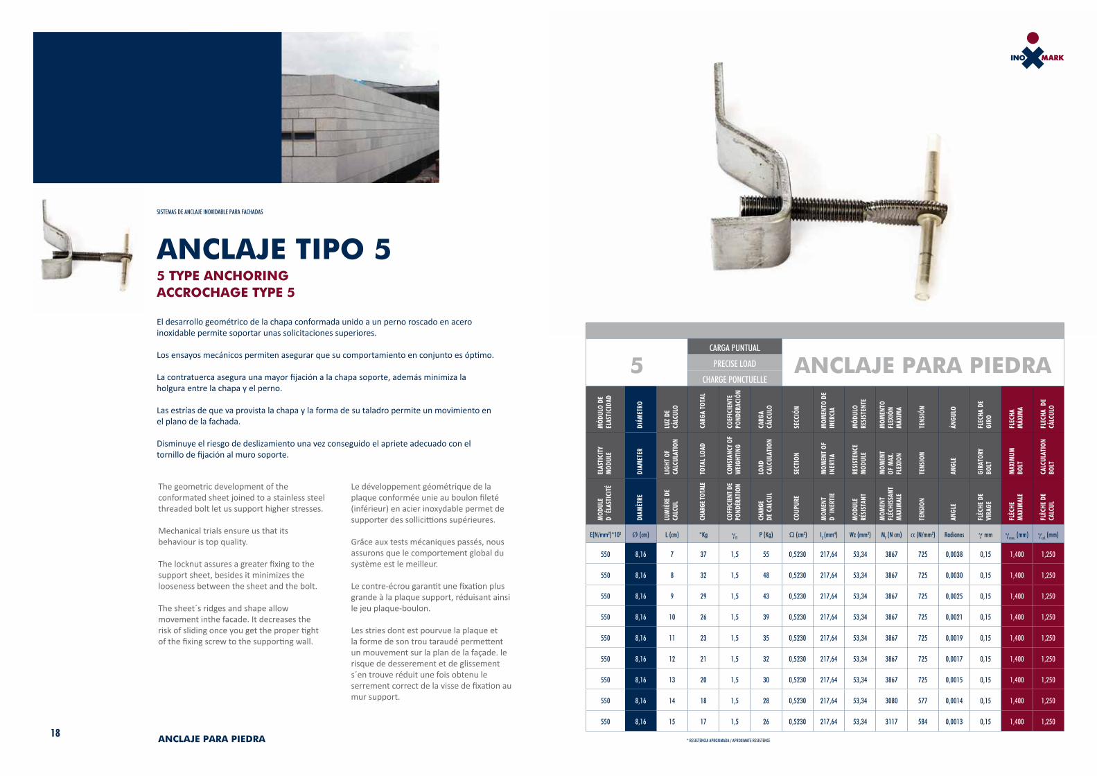
El desarrollo geométrico de la chapa conformada unido a un perno roscado en acero inoxidable permite soportar unas solicitaciones superiores. Los ensayos mecánicos permiten asegurar que su comportamiento en conjunto es óptimo.
La contratuerca asegura una mayor fijación a la chapa soporte, además minimiza la holgura entre la chapa y el perno.
Las estrías de que va provista la chapa y la forma de su taladro permite un movimiento en el plano de la fachada.
Disminuye el riesgo de deslizamiento una vez conseguido el apriete adecuado con el tornillo de fijación al muro soporte.
The geometric development of the conformated sheet joined to a stainless steel threaded bolt let us support higher stresses.
Mechanical trials ensure us that its behaviour is top quality.
The locknut assures a greater fixing to the support sheet, besides it minimizes the looseness between the sheet and the bolt.
The sheet´s ridges and shape allow movement inthe facade. It decreases the risk of sliding once you get the proper tight of the fixing screw to the supporting wall.
5CARGA PUNTUAL
ANCLAJE PARA PIEDRAPRECISE LOAD
CHARGE PONCTUELLE
MÓD
ULO
DE
ELAS
TICI
DAD
DIÁM
ETRO
LUZ
DE
CÁLC
ULO
CARG
A TO
TAL
COEF
ICIE
NTE
POND
ERAC
IÓN
CARG
A CÁ
LCUL
O
SECC
IÓN
MOM
ENTO
DE
INER
CIA
MÓD
ULO
RESI
STEN
TE
MOM
ENTO
FL
EXIÓ
N M
ÁXIM
A
TENS
IÓN
ÁNGU
LO
FLEC
HA D
E GI
RO
FLEC
HA
MÁX
IMA
FLEC
HA D
E CÁ
LCUL
O
ELAS
TICI
TY
MOD
ULE
DIAM
ETER
LIGH
T OF
CA
LCUL
ATIO
N
TOTA
L LO
AD
CONS
TANC
Y OF
W
EIGH
TING
LOAD
CA
LCUL
ATIO
N
SECT
ION
MOM
ENT
OF
INER
TIA
RESI
STEN
CE
MOD
ULE
MOM
ENT
OF M
AX.
FLEX
ION
TENS
ION
ANGL
E
GIRA
TORY
BO
LT
MAX
IMUM
BO
LT
CALC
ULAT
ION
BOLT
MOD
ULE
D´ÉL
ASTI
CITÉ
DIAM
ÈTRE
LUM
IÈRE
DE
CALC
UL
CHAR
GE TO
TALE
COFF
ICIE
NT D
E PO
NDÉR
ATIO
N
CHAR
GE
DE C
ALCU
L
COUP
URE
MOM
ENT
D´IN
ERTI
E
MOD
ULE
RÉSI
STAN
T
MOM
ENT
FLÉC
HISS
ANT
MAX
IMAL
E
TENS
ION
ANGL
E
FLÈC
HE D
E VI
RAGE
FLÈC
HE
MAX
IMAL
E
FLÈC
HE D
E CA
LCUL
E(N/mm2)*103 Ø (cm) L (cm) *Kg γf1 P (Kg) Ω (cm2) I2 (mm4) Wz (mm3) Mf (N cm) α (N/mm2) Radianes γ mm γmax. (mm) γcal. (mm)
550 8,16 7 37 1,5 55 0,5230 217,64 53,34 3867 725 0,0038 0,15 1,400 1,250
550 8,16 8 32 1,5 48 0,5230 217,64 53,34 3867 725 0,0030 0,15 1,400 1,250
550 8,16 9 29 1,5 43 0,5230 217,64 53,34 3867 725 0,0025 0,15 1,400 1,250
550 8,16 10 26 1,5 39 0,5230 217,64 53,34 3867 725 0,0021 0,15 1,400 1,250
550 8,16 11 23 1,5 35 0,5230 217,64 53,34 3867 725 0,0019 0,15 1,400 1,250
550 8,16 12 21 1,5 32 0,5230 217,64 53,34 3867 725 0,0017 0,15 1,400 1,250
550 8,16 13 20 1,5 30 0,5230 217,64 53,34 3867 725 0,0015 0,15 1,400 1,250
550 8,16 14 18 1,5 28 0,5230 217,64 53,34 3080 577 0,0014 0,15 1,400 1,250
550 8,16 15 17 1,5 26 0,5230 217,64 53,34 3117 584 0,0013 0,15 1,400 1,250
* RESISTENCIA APROXIMADA / APROXIMATE RESISTENCE
Le développement géométrique de la plaque conformée unie au boulon fileté (inférieur) en acier inoxydable permet de supporter des sollicittions supérieures.
Grâce aux tests mécaniques passés, nous assurons que le comportement global du système est le meilleur.
Le contre-écrou garantit une fixation plus grande à la plaque support, réduisant ainsi le jeu plaque-boulon.
Les stries dont est pourvue la plaque et la forme de son trou taraudé permettent un mouvement sur la plan de la façade. le risque de desserement et de glissement s´en trouve réduit une fois obtenu le serrement correct de la visse de fixation au mur support.
ANCLAJE TIPO 55 TYPE ANCHORINGACCROCHAGE TYPE 5

20 ANCLAJE PARA PIEDRA
La constante evolución en busca de soluciones más eficientes conduce al desarrollo de este anclaje.
La calidad de los materiales, al igual que en el resto de los productos, es garantía de seguridad.
Su conjunto permite el desplazamiento en el plano de la fachada, en un eje perpendicular a la misma y además en un eje perpendicular al anterior.
La libertad de movimiento es la misma que garantiza adecuadamente la seguridad del conjunto anclaje-fachada.
The constant improvement towards more efficient solutions brings us to the development of this anchoring.
The quality of the material as well as the rest of our products are safety guarantees.
Its composition allows sliding in the facade plan, in a perpendicular axis as well as in an axis perpendicular to the latter.
The freedom of movement is the maxin that properly guarantees the security of the whole anchoring-facade.
6CARGA PUNTUAL
ANCLAJE PARA PIEDRAPRECISE LOAD
CHARGE PONCTUELLE
MÓD
ULO
DE
ELAS
TICI
DAD
DIÁM
ETRO
LUZ
DE
CÁLC
ULO
CARG
A TO
TAL
COEF
ICIE
NTE
POND
ERAC
IÓN
CARG
A CÁ
LCUL
O
SECC
IÓN
MOM
ENTO
DE
INER
CIA
MÓD
ULO
RESI
STEN
TE
MOM
ENTO
FL
EXIÓ
N M
ÁXIM
A
TENS
IÓN
ÁNGU
LO
FLEC
HA D
E GI
RO
FLEC
HA
MÁX
IMA
FLEC
HA D
E CÁ
LCUL
O
ELAS
TICI
TY
MOD
ULE
DIAM
ETER
LIGH
T OF
CA
LCUL
ATIO
N
TOTA
L LO
AD
CONS
TANC
Y OF
W
EIGH
TING
LOAD
CA
LCUL
ATIO
N
SECT
ION
MOM
ENT
OF
INER
TIA
RESI
STEN
CE
MOD
ULE
MOM
ENT
OF M
AX.
FLEX
ION
TENS
ION
ANGL
E
GIRA
TORY
BO
LT
MAX
IMUM
BO
LT
CALC
ULAT
ION
BOLT
MOD
ULE
D´ÉL
ASTI
CITÉ
DIAM
ÈTRE
LUM
IÈRE
DE
CALC
UL
CHAR
GE TO
TALE
COFF
ICIE
NT D
E PO
NDÉR
ATIO
N
CHAR
GE
DE C
ALCU
L
COUP
URE
MOM
ENT
D´IN
ERTI
E
MOD
ULE
RÉSI
STAN
T
MOM
ENT
FLÉC
HISS
ANT
MAX
IMAL
E
TENS
ION
ANGL
E
FLÈC
HE D
E VI
RAGE
FLÈC
HE
MAX
IMAL
E
FLÈC
HE D
E CA
LCUL
E(N/mm2)*103 Ø (cm) L (cm) *Kg γf1 P (Kg) Ω (cm2) I2 (mm4) Wz (mm3) Mf (N cm) α (N/mm2) Radianes γ mm γmax. (mm) γcal. (mm)
550 8,16 7 33 1,5 50 0,5230 217,64 53,34 3467 650 0,0038 0,15 1,400 1,250
550 8,16 8 29 1,5 43 0,5230 217,64 53,34 3467 650 0,0030 0,15 1,400 1,250
550 8,16 9 26 1,5 39 0,5230 217,64 53,34 3467 650 0,0025 0,15 1,400 1,250
550 8,16 10 23 1,5 35 0,5230 217,64 53,34 3467 650 0,0021 0,15 1,400 1,250
550 8,16 11 21 1,5 32 0,5230 217,64 53,34 3467 650 0,0019 0,15 1,400 1,250
550 8,16 12 19 1,5 29 0,5230 217,64 53,34 3467 650 0,0017 0,15 1,400 1,250
550 8,16 13 19 1,5 27 0,5230 217,64 53,34 3467 650 0,0015 0,15 1,400 1,250
550 8,16 14 17 1,5 26 0,5230 217,64 53,34 2860 536 0,0014 0,15 1,400 1,250
550 8,16 15 15 1,5 23 0,5230 217,64 53,34 2760 517 0,0013 0,15 1,400 1,250
* RESISTENCIA APROXIMADA / APROXIMATE RESISTENCE
SISTEMAS DE ANCLAJE INOXIDABLE PARA FACHADAS
ANCLAJE TIPO 66 TYPE ANCHORINGACCROCHAGE TYPE 6
Dans le souci constant de rechercher de solutions pls efficaces, nous avons conçu cet accrochage de type 6.
La qualité des matériaux de même que les autres produits demeure une garantie de sécurité.
L´endemble permet le déplacement sur le plan de la façade sur un axe perpendiculaire á celle-ci et en plus sur un axe perpendiculaire au précédent.
La liberté des mouvements portée á son maximum garantie de façon efficace la sécurité de l´ensemble accrochage-façade.

23
ANCLAJEPARACERÁMICACERAMIC ANCHORAGEANCRAGE POUR CÉRAMIQUE
24 ANCLAJE PARA CERÁMICA
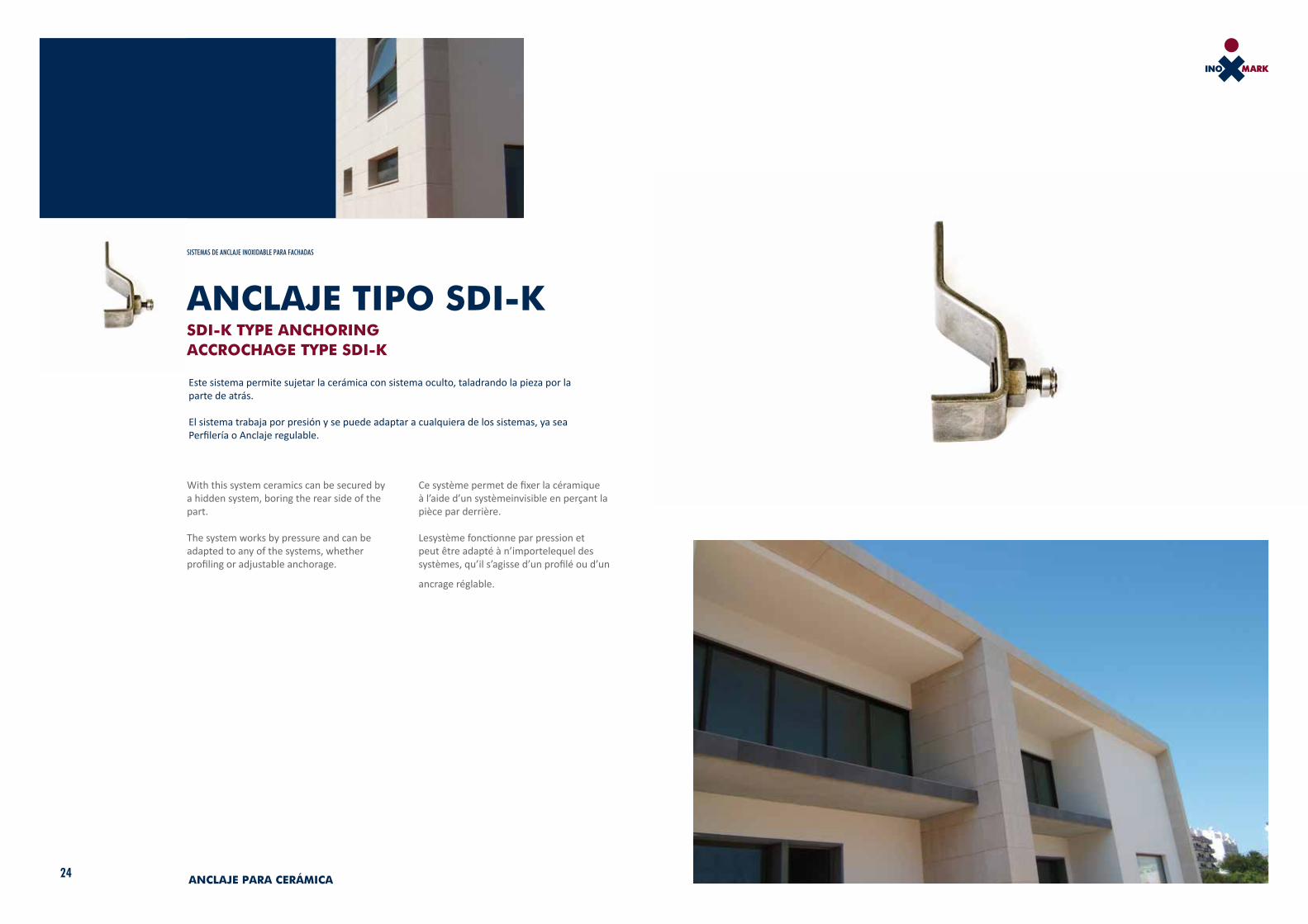
Este sistema permite sujetar la cerámica con sistema oculto, taladrando la pieza por la parte de atrás. El sistema trabaja por presión y se puede adaptar a cualquiera de los sistemas, ya sea Perfilería o Anclaje regulable.
SISTEMAS DE ANCLAJE INOXIDABLE PARA FACHADAS
With this system ceramics can be secured by a hidden system, boring the rear side of the part.
The system works by pressure and can be adapted to any of the systems, whether profiling or adjustable anchorage.
ANCLAJE TIPO SDI-KSDI-K TYPE ANCHORINGACCROCHAGE TYPE SDI-K
Ce système permet de fixer la céramique à l’aide d’un systèmeinvisible en perçant la pièce par derrière.
Lesystème fonctionne par pression et peut être adapté à n’importelequel des systèmes, qu’il s’agisse d’un profilé ou d’un
ancrage réglable.

26 ANCLAJE PARA CERÁMICA
Anclaje diseñado para el aplacado de cerámica. Se puede colocar directo a pared con resina o taco, se puede poner sobre Perfilería o utilizar con anclaje regulable.
Lleva un muelle de presión que consigue apretar la placa de cerámica evitando holguras.
SISTEMAS DE ANCLAJE INOXIDABLE PARA FACHADAS
Anchorage designed for ceramic applications.
It can be fitted directly on a wall with resin or dowel, it can be placed on profiling or used with adjustable anchorage.
It has a pressure spring with which the ceramic plate can be tightened avoiding gaps.
ANCLAJE CER-15CER-15 ANCHORINGACCROCHAGE CER-15
Ancrageconçu pour le placage céramique. Il peut être directement fixé sur un mur à l’aide d’une résine ou d’une cheville, peut être placé sur un profiléou être utilisé avec un ancrage réglable.
Il est muni d’un ressort de pression qui parvient à serrer la plaque céramique évitant qu’il y ait des jeux.
CER-15 ANCLAJE PARA CERÁMICA
DIMENSIONES PLACAS EN CM PESO DIMENSIONES APOYO DE LA PLACAS EN MM Mf en Nmm TENSIONES N/m3mDEFORMACIÓN
MÁXIMA mm
PLATE DIMENSIONS IN CM WEIGHT DIMENSIONS OF SUPPORT ON PLATES IN MM Mf en Nmm STRESSES N/m3mMAXIMUM
DEFORMATION mm
DIMENSIONS PLAQUESEN CM POIDS DIMENSIONS APPUI DES PLAQUES EN MM Mf en Nmm TENSIONS N/m3mDÉFORMATION MAXIMALE mm
LARGO ANCHO ESPESOR KG ANCHO ESPESOR L HORIZONTAL L VERTICAL IZmm4 WZmm3 PUNTUAL UNIFORME PUNTUAL UNIFORME PUNTUAL UNIFORME
LENGTH WIDTH THICKNESS KG WIDTH THICKNESS HORIZONTAL SIDE
VERTICAL SIDE IZmm4 WZmm3 SPECIFIC EVEN SPECIFIC EVEN SPECIFIC EVEN
LONGUEUR LARGEUR ÉPAISSEUR KG LARGEUR ÉPAISSEUR CÔTÉ HORIZONTAL
CÔTÉ VERTICAL IZmm4 WZmm3 PRÉCIS UNIFORME PRÉCIS UNIFORME PRÉCIS UNIFORME
80 40 1,5 13 20 1,5 15 15 5,625 7,500 972 486 129,60 64,8 0,00617 0,00077
80 50 1,5 16,2 20 1,5 15 15 5,625 7,500 1215 607,5 162 81 0,00771 0,00096
80 60 1,5 19,4 20 1,5 15 15 5,625 7,500 1458 729 194,4 97,2 0,00926 0,00116
80 70 1,5 22,7 20 1,5 15 15 5,625 7,500 1701 850,5 226,8 113,4 0,01080 0,00135
100 40 1,5 16,2 20 1,5 15 15 5,625 7,500 1215 607,5 162 81 0,00771 0,00096
100 50 1,5 20,3 20 1,5 15 15 5,625 7,500 1518,75 759,375 202,5 101,25 0,00964 0,00121
100 60 1,5 24,3 20 1,5 15 15 5,625 7,500 1822,5 911,25 243 121,5 0,01157 0,00145
100 70 1,5 28,4 20 1,5 15 15 5,625 7,500 2126,25 1063,125 283,5 141,75 0,01350 0,00169
120 40 1,5 24,3 20 1,5 15 15 5,625 7,500 1822,5 911,25 243 121,5 0,01157 0,00145
120 50 1,5 29,2 20 1,5 15 15 5,625 7,500 2187 1093,5 291,6 145,8 0,01389 0,00174
120 60 1,5 34 20 1,5 15 15 5,625 7,500 2551,5 1275,75 340,2 170,1 0,01620 0,00203
120 70 1,5 38,9 20 1,5 15 15 5,625 7,500 2916 1458 388,8 194,4 0,01851 0,00231
180 40 1,5 43,7 20 1,5 15 15 5,625 7,500 3280,50 1640,25 437,4 218,7 0,02083 0,00260
180 50 1,5 51 20 1,5 15 15 5,625 7,500 3827,25 1913,625 510,3 255,15 0,02430 0,00304
180 60 1,5 58,3 20 1,5 15 15 5,625 7,500 4374 2187 583,2 291,6 0,02777 0,00347
180 70 1,5 65,6 20 1,5 15 15 5,625 7,500 4920,75 2460,375 655,1 328,05 0,03124 0,00391
29
Diseñados especialmente para pizarra, permiten colocarse
directamente a pared con resina, o taco, así como con Perfilería
o con Anclaje regulable, dependiendo de que sean roscados o
corrugados.
Specially designed for slate, can be fitted directly on wall with
resin, or dowel, and also with profiling or with adjustable
Anchorage, depending on whether this is screwed or corrugated.
ANCLAJEPARAPIZARRAANCHORAGE FOR SLATEANCRAGE POUR ARDOISES
Spécialement conçus pour des ardoises, ils peuvent être
directement fixés au mur à l’aide d’une résine ou d’une cheville
tout comme avec un profilé ou un ancrage réglableselon qu’ils
sont filetés ou ondulés.
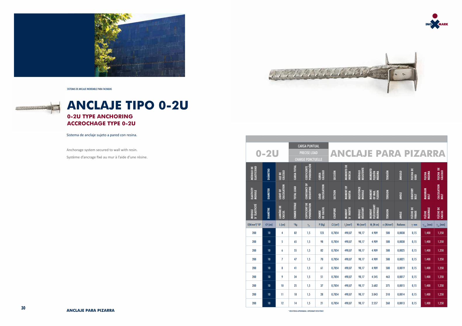
Sistema de anclaje sujeto a pared con resina.
Anchorage system secured to wall with resin.
Système d’ancrage fixé au mur à l’aide d’une résine.
ANCLAJE TIPO 0-2U0-2U TYPE ANCHORINGACCROCHAGE TYPE 0-2U
30 ANCLAJE PARA PIZARRA
SISTEMAS DE ANCLAJE INOXIDABLE PARA FACHADAS
0-2UCARGA PUNTUAL
ANCLAJE PARA PIZARRAPRECISE LOAD
CHARGE PONCTUELLE
MÓD
ULO
DE
ELAS
TICI
DAD
DIÁM
ETRO
LUZ
DE
CÁLC
ULO
CARG
A TO
TAL
COEF
ICIE
NTE
POND
ERAC
IÓN
CARG
A CÁ
LCUL
O
SECC
IÓN
MOM
ENTO
DE
INER
CIA
MÓD
ULO
RESI
STEN
TE
MOM
ENTO
FL
EXIÓ
N M
ÁXIM
A
TENS
IÓN
ÁNGU
LO
FLEC
HA D
E GI
RO
FLEC
HA
MÁX
IMA
FLEC
HA D
E CÁ
LCUL
O
ELAS
TICI
TY
MOD
ULE
DIAM
ETER
LIGH
T OF
CA
LCUL
ATIO
N
TOTA
L LO
AD
CONS
TANC
Y OF
W
EIGH
TING
LOAD
CA
LCUL
ATIO
N
SECT
ION
MOM
ENT
OF
INER
TIA
RESI
STEN
CE
MOD
ULE
MOM
ENT
OF M
AX.
FLEX
ION
TENS
ION
ANGL
E
GIRA
TORY
BO
LT
MAX
IMUM
BO
LT
CALC
ULAT
ION
BOLT
MOD
ULE
D´ÉL
ASTI
CITÉ
DIAM
ÈTRE
LUM
IÈRE
DE
CALC
UL
CHAR
GE TO
TALE
COFF
ICIE
NT D
E PO
NDÉR
ATIO
N
CHAR
GE
DE C
ALCU
L
COUP
URE
MOM
ENT
D´IN
ERTI
E
MOD
ULE
RÉSI
STAN
T
MOM
ENT
FLÉC
HISS
ANT
MAX
IMAL
E
TENS
ION
ANGL
E
FLÈC
HE D
E VI
RAGE
FLÈC
HE
MAX
IMAL
E
FLÈC
HE D
E CA
LCUL
E(N/mm2)*103 Ø (cm) L (cm) *Kg γf1 P (Kg) Ω (cm2) I2 (mm4) Wz (mm3) Mf (N cm) α (N/mm2) Radianes γ mm γmax. (mm) γcal. (mm)
200 10 4 82 1,5 123 0,7854 490,87 98,17 4.909 500 0,0038 0,15 1,400 1,250
200 10 5 65 1,5 98 0,7854 490,87 98,17 4.909 500 0,0030 0,15 1,400 1,250
200 10 6 55 1,5 82 0,7854 490,87 98,17 4.909 500 0,0025 0,15 1,400 1,250
200 10 7 47 1,5 70 0,7854 490,87 98,17 4.909 500 0,0021 0,15 1,400 1,250
200 10 8 41 1,5 61 0,7854 490,87 98,17 4.909 500 0,0019 0,15 1,400 1,250
200 10 9 34 1,5 51 0,7854 490,87 98,17 4.545 463 0,0017 0,15 1,400 1,250
200 10 10 25 1,5 37 0,7854 490,87 98,17 3.682 375 0,0015 0,15 1,400 1,250
200 10 11 18 1,5 28 0,7854 490,87 98,17 3.043 310 0,0014 0,15 1,400 1,250
200 10 12 14 1,5 21 0,7854 490,87 98,17 2.557 260 0,0013 0,15 1,400 1,250
* RESISTENCIA APROXIMADA / APROXIMATE RESISTENCE

32 ANCLAJE PARA PIZARRA
Sistema de anclaje roscado para una mayor precisión en el montaje.
Screwed anchorage system for greater precision when mounting.
Système d’ancrage fileté pour plus de précision lors du montage.
ANCLAJE TIPO 1-2U1-2U TYPE ANCHORINGACCROCHAGE TYPE 1-2U
SISTEMAS DE ANCLAJE INOXIDABLE PARA FACHADAS
1-2UCARGA PUNTUAL
ANCLAJE PARA PIZARRAPRECISE LOAD
CHARGE PONCTUELLE
MÓD
ULO
DE
ELAS
TICI
DAD
DIÁM
ETRO
LUZ
DE
CÁLC
ULO
CARG
A TO
TAL
COEF
ICIE
NTE
POND
ERAC
IÓN
CARG
A CÁ
LCUL
O
SECC
IÓN
MOM
ENTO
DE
INER
CIA
MÓD
ULO
RESI
STEN
TE
MOM
ENTO
FL
EXIÓ
N M
ÁXIM
A
TENS
IÓN
ÁNGU
LO
FLEC
HA D
E GI
RO
FLEC
HA
MÁX
IMA
FLEC
HA D
E CÁ
LCUL
O
ELAS
TICI
TY
MOD
ULE
DIAM
ETER
LIGH
T OF
CA
LCUL
ATIO
N
TOTA
L LO
AD
CONS
TANC
Y OF
W
EIGH
TING
LOAD
CA
LCUL
ATIO
N
SECT
ION
MOM
ENT
OF
INER
TIA
RESI
STEN
CE
MOD
ULE
MOM
ENT
OF M
AX.
FLEX
ION
TENS
ION
ANGL
E
GIRA
TORY
BO
LT
MAX
IMUM
BO
LT
CALC
ULAT
ION
BOLT
MOD
ULE
D´ÉL
ASTI
CITÉ
DIAM
ÈTRE
LUM
IÈRE
DE
CALC
UL
CHAR
GE TO
TALE
COFF
ICIE
NT D
E PO
NDÉR
ATIO
N
CHAR
GE
DE C
ALCU
L
COUP
URE
MOM
ENT
D´IN
ERTI
E
MOD
ULE
RÉSI
STAN
T
MOM
ENT
FLÉC
HISS
ANT
MAX
IMAL
E
TENS
ION
ANGL
E
FLÈC
HE D
E VI
RAGE
FLÈC
HE
MAX
IMAL
E
FLÈC
HE D
E CA
LCUL
E(N/mm2)*103 Ø (cm) L (cm) *Kg γf1 P (Kg) Ω (cm2) I2 (mm4) Wz (mm3) Mf (N cm) α (N/mm2) Radianes γ mm γmax. (mm) γcal. (mm)
550 8,16 4 64 1,5 97 0,5230 217,64 53,34 3867 725 0,0038 0,15 1,400 1,250
550 8,16 5 52 1,5 77 0,5230 217,64 53,34 3867 725 0,0030 0,15 1,400 1,250
550 8,16 6 43 1,5 64 0,5230 217,64 53,34 3867 725 0,0025 0,15 1,400 1,250
550 8,16 7 37 1,5 55 0,5230 217,64 53,34 3867 725 0,0021 0,15 1,400 1,250
550 8,16 8 32 1,5 48 0,5230 217,64 53,34 3867 725 0,0019 0,15 1,400 1,250
550 8,16 9 29 1,5 43 0,5230 217,64 53,34 3867 725 0,0017 0,15 1,400 1,250
550 8,16 10 26 1,5 39 0,5230 217,64 53,34 3867 725 0,0015 0,15 1,400 1,250
550 8,16 11 22 1,5 34 0,5230 217,64 53,34 3710 695 0,0014 0,15 1,400 1,250
550 8,16 12 17 1,5 26 0,5230 217,64 53,34 3117 584 0,0013 0,15 1,400 1,250
* RESISTENCIA APROXIMADA / APROXIMATE RESISTENCE

34 ANCLAJE PARA PIZARRA
SISTEMAS DE ANCLAJE INOXIDABLE PARA FACHADAS
Sistema de anclaje de regulación múltiple, en tres ejes.
Système d’ancrage à réglage multiple, en trois axes.
Multiple adjustment anchorage system, on three shafts.
ANCLAJE TIPO 5-2U5-2U TYPE ANCHORINGACCROCHAGE TYPE 5-2U
5-2UCARGA PUNTUAL
ANCLAJE PARA PIZARRAPRECISE LOAD
CHARGE PONCTUELLE
MÓD
ULO
DE
ELAS
TICI
DAD
DIÁM
ETRO
LUZ
DE
CÁLC
ULO
CARG
A TO
TAL
COEF
ICIE
NTE
POND
ERAC
IÓN
CARG
A CÁ
LCUL
O
SECC
IÓN
MOM
ENTO
DE
INER
CIA
MÓD
ULO
RESI
STEN
TE
MOM
ENTO
FL
EXIÓ
N M
ÁXIM
A
TENS
IÓN
ÁNGU
LO
FLEC
HA D
E GI
RO
FLEC
HA
MÁX
IMA
FLEC
HA D
E CÁ
LCUL
O
ELAS
TICI
TY
MOD
ULE
DIAM
ETER
LIGH
T OF
CA
LCUL
ATIO
N
TOTA
L LO
AD
CONS
TANC
Y OF
W
EIGH
TING
LOAD
CA
LCUL
ATIO
N
SECT
ION
MOM
ENT
OF
INER
TIA
RESI
STEN
CE
MOD
ULE
MOM
ENT
OF M
AX.
FLEX
ION
TENS
ION
ANGL
E
GIRA
TORY
BO
LT
MAX
IMUM
BO
LT
CALC
ULAT
ION
BOLT
MOD
ULE
D´ÉL
ASTI
CITÉ
DIAM
ÈTRE
LUM
IÈRE
DE
CALC
UL
CHAR
GE TO
TALE
COFF
ICIE
NT D
E PO
NDÉR
ATIO
N
CHAR
GE
DE C
ALCU
L
COUP
URE
MOM
ENT
D´IN
ERTI
E
MOD
ULE
RÉSI
STAN
T
MOM
ENT
FLÉC
HISS
ANT
MAX
IMAL
E
TENS
ION
ANGL
E
FLÈC
HE D
E VI
RAGE
FLÈC
HE
MAX
IMAL
E
FLÈC
HE D
E CA
LCUL
E(N/mm2)*103 Ø (cm) L (cm) *Kg γf1 P (Kg) Ω (cm2) I2 (mm4) Wz (mm3) Mf (N cm) α (N/mm2) Radianes γ mm γmax. (mm) γcal. (mm)
550 8,16 7 37 1,5 55 0,5230 217,64 53,34 3867 725 0,0038 0,15 1,400 1,250
550 8,16 8 32 1,5 48 0,5230 217,64 53,34 3867 725 0,0030 0,15 1,400 1,250
550 8,16 9 29 1,5 43 0,5230 217,64 53,34 3867 725 0,0025 0,15 1,400 1,250
550 8,16 10 26 1,5 39 0,5230 217,64 53,34 3867 725 0,0021 0,15 1,400 1,250
550 8,16 11 23 1,5 35 0,5230 217,64 53,34 3867 725 0,0019 0,15 1,400 1,250
550 8,16 12 21 1,5 32 0,5230 217,64 53,34 3867 725 0,0017 0,15 1,400 1,250
550 8,16 13 20 1,5 30 0,5230 217,64 53,34 3867 725 0,0015 0,15 1,400 1,250
550 8,16 14 18 1,5 28 0,5230 217,64 53,34 3080 577 0,0014 0,15 1,400 1,250
550 8,16 15 17 1,5 26 0,5230 217,64 53,34 3117 584 0,0013 0,15 1,400 1,250
* RESISTENCIA APROXIMADA / APROXIMATE RESISTENCE

37
PROFILINGPROFILÉ
PERFILERÍA
Se compone de perfil, placa anclaje y sujeción a muro con los tacos necesarios para cada tipo de pared.
Su regulación está basada en el giro de la tuerca dispuesta en la placa para tal fin, este sistema además de comodidad y precisión en la regulación, puede evitar el uso de escuadras y demás elementos, para su colocación.
Se pueden utilizar distintos sistemas de Anclaje dependiendo del material que se quiera sujetar.
Se fabrica en calidad AISI 304 y ASIS 316 y en formatos 40x20 y 40x40
Consists of profile, anchorage plate and fastening to wall with the necessary dowels for each type of wall.
It can be adjusted by turning the nut found on the plate for that purpose. Apart from being easy and precise to adjust, with this system no brackets or other parts are needed to mount it.
Different Anchorage systems can be used depending on what material we want to fix.
Made in AISI 304 and ASIS 316 quality and in 40x20 and 40x40 formats.
Il est composé de profil,plaqued’ancrageet fixation au murà l’aide de chevilles adaptées à chaque type de mur.
Son réglage se fait en tournant l’écrou disposé sur la plaqueà cette fin. En plus du confort et de la précision lors du réglage, ce système permet d’éviter l’utilisation d’équerres et d’autres éléments pour sa pose.
Différents systèmes d’Ancrage peuvent être utilisés en fonction du matériel que l’on veut fixer.
Il est fabriqué dans la qualité AISI 304 et ASIS 316 et est disponible en formats 40x20 et 40x40

38 39
PERFILERIA PARA PIEDRASTONE PROFILING
SISTEMAS DE ANCLAJE INOXIDABLE PARA FACHADAS
PROFILÉ POUR PIERRE
PERFILERIA PARAPIEDRA RANURADAGROOVED STONE PROFILING
PROFILÉ POUR PIERRE RAINURÉE
PERFILERIA PARACERÁMICA SDKSDK CERAMIC PROFILING
PROFILÉ POUR CÉRAMIQUE SDK
PERFILERIA PARAPIZARRA 2U2U SLATE PROFILING
PROFILÉ POUR ARDOISE 2U

41
VARIOSMISCELLANEOUS
DIVERS
42 43
RESINARESIN
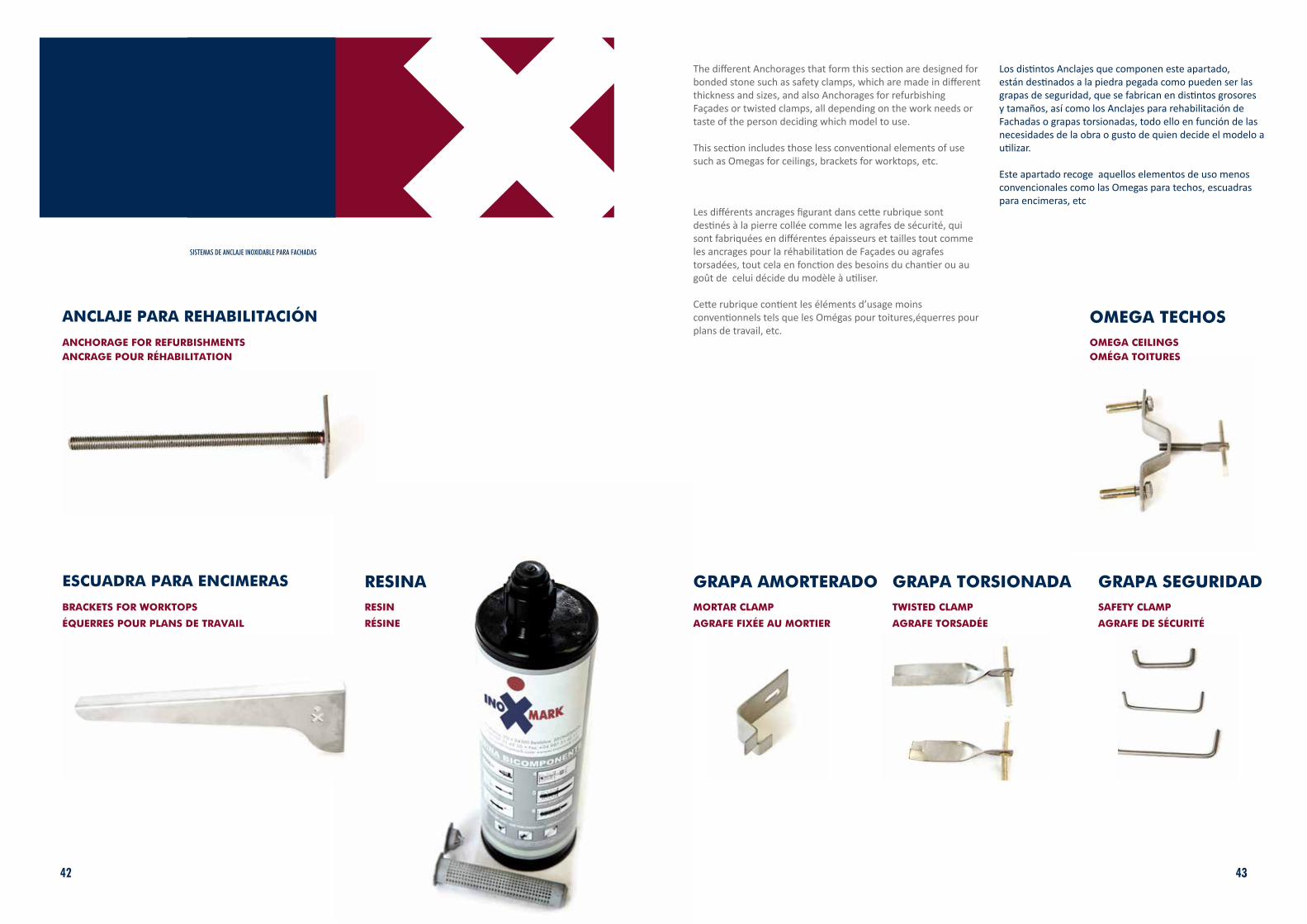
ANCLAJE PARA REHABILITACIÓN
Los distintos Anclajes que componen este apartado, están destinados a la piedra pegada como pueden ser las grapas de seguridad, que se fabrican en distintos grosores y tamaños, así como los Anclajes para rehabilitación de Fachadas o grapas torsionadas, todo ello en función de las necesidades de la obra o gusto de quien decide el modelo a utilizar.
Este apartado recoge aquellos elementos de uso menos convencionales como las Omegas para techos, escuadras para encimeras, etc
ANCHORAGE FOR REFURBISHMENTS
The different Anchorages that form this section are designed for bonded stone such as safety clamps, which are made in different thickness and sizes, and also Anchorages for refurbishing Façades or twisted clamps, all depending on the work needs or taste of the person deciding which model to use.
This section includes those less conventional elements of use such as Omegas for ceilings, brackets for worktops, etc.
SISTEMAS DE ANCLAJE INOXIDABLE PARA FACHADAS
ESCUADRA PARA ENCIMERAS
BRACKETS FOR WORKTOPS
GRAPA AMORTERADOMORTAR CLAMP
GRAPA TORSIONADATWISTED CLAMP
GRAPA SEGURIDADSAFETY CLAMP
OMEGA TECHOSOMEGA CEILINGS
Les différents ancrages figurant dans cette rubrique sont destinés à la pierre collée comme les agrafes de sécurité, qui sont fabriquées en différentes épaisseurs et tailles tout comme les ancrages pour la réhabilitation de Façades ou agrafes torsadées, tout cela en fonction des besoins du chantier ou au goût de celui décide du modèle à utiliser.
Cette rubrique contient les éléments d’usage moins conventionnels tels que les Omégas pour toitures,équerres pour plans de travail, etc.
ANCRAGE POUR RÉHABILITATION
ÉQUERRES POUR PLANS DE TRAVAIL RÉSINE AGRAFE FIXÉE AU MORTIER AGRAFE TORSADÉE AGRAFE DE SÉCURITÉ
OMÉGA TOITURES

PARQUE INDUSTRIAL DEL BIERZO ALTOVía Augusta s/n. 24300 Bembibre. León. EspañaT.+34 987 514 510
www.inoxmark.com [email protected]


![K^d Ed hD E < W > 'hEd ' > Á Á Á X u P ] P o U o } P } X ... · K^d Ed hD E < W > 'hEd ' > Á Á Á X u P ] P o U o } P } X } u í X /K W Á Á Á X o](https://static.fdocuments.es/doc/165x107/5e474855abf6be486949aeb5/kd-ed-hd-e-w-hed-x-u-p-p-o-u-o-p-x-kd-ed.jpg)