Three dimensional acoustic tweezers with vortex streaming
9
This document is downloaded from DR‑NTU (https://dr.ntu.edu.sg) Nanyang Technological University, Singapore. Three dimensional acoustic tweezers with vortex streaming Li, Junfei; Crivoi, Alexandru; Peng, Xiuyuan; Shen, Lu; Pu, Yunjiao; Fan, Zheng; Cummer, Steven A. 2021 Li, J., Crivoi, A., Peng, X., Shen, L., Pu, Y., Fan, Z. & Cummer, S. A. (2021). Three dimensional acoustic tweezers with vortex streaming. Communications Physics, 4(1), 113‑. https://dx.doi.org/10.1038/s42005‑021‑00617‑0 https://hdl.handle.net/10356/152955 https://doi.org/10.1038/s42005‑021‑00617‑0 © 2021 The Author(s). This article is licensed under a Creative CommonsAttribution 4.0 International License, which permits use, sharing,adaptation, distribution and reproduction in any medium or format, as long as you giveappropriate credit to the original author(s) and the source, provide a link to the CreativeCommons license, and indicate if changes were made. The images or other third partymaterial in this article are included in the article’s Creative Commons license, unlessindicated otherwise in a credit line to the material. If material is not included in thearticle’s Creative Commons license and your intended use is not permitted by statutoryregulation or exceeds the permitted use, you will need to obtain permission directly fromthe copyright holder. To view a copy of this license, visit http://creativecommons.org/licenses/by/4.0/. Downloaded on 27 Mar 2022 08:47:46 SGT
Transcript of Three dimensional acoustic tweezers with vortex streaming

This document is downloaded from DR‑NTU (https://dr.ntu.edu.sg)Nanyang Technological University, Singapore.
Three dimensional acoustic tweezers with vortexstreaming
Li, Junfei; Crivoi, Alexandru; Peng, Xiuyuan; Shen, Lu; Pu, Yunjiao; Fan, Zheng; Cummer,Steven A.
2021
Li, J., Crivoi, A., Peng, X., Shen, L., Pu, Y., Fan, Z. & Cummer, S. A. (2021). Threedimensional acoustic tweezers with vortex streaming. Communications Physics, 4(1), 113‑.https://dx.doi.org/10.1038/s42005‑021‑00617‑0
https://hdl.handle.net/10356/152955
https://doi.org/10.1038/s42005‑021‑00617‑0
© 2021 The Author(s). This article is licensed under a Creative CommonsAttribution 4.0International License, which permits use, sharing,adaptation, distribution andreproduction in any medium or format, as long as you giveappropriate credit to the originalauthor(s) and the source, provide a link to the CreativeCommons license, and indicate ifchanges were made. The images or other third partymaterial in this article are included inthe article’s Creative Commons license, unlessindicated otherwise in a credit line to thematerial. If material is not included in thearticle’s Creative Commons license and yourintended use is not permitted by statutoryregulation or exceeds the permitted use, you willneed to obtain permission directly fromthe copyright holder. To view a copy of this license,visit http://creativecommons.org/licenses/by/4.0/.
Downloaded on 27 Mar 2022 08:47:46 SGT

ARTICLE
Three dimensional acoustic tweezers with vortexstreamingJunfei Li 1,3, Alexandru Crivoi2,3, Xiuyuan Peng1, Lu Shen 2, Yunjiao Pu1, Zheng Fan 2✉ &
Steven A. Cummer1✉
Acoustic tweezers use ultrasound for contact-free manipulation of particles from millimeter
to sub-micrometer scale. Particle trapping is usually associated with either radiation forces or
acoustic streaming fields. Acoustic tweezers based on single-beam focused acoustic vortices
have attracted considerable attention due to their selective trapping capability, but have
proven difficult to use for three-dimensional (3D) trapping without a complex transducer
array and significant constraints on the trapped particle properties. Here we demonstrate a
3D acoustic tweezer in fluids that uses a single transducer and combines the radiation force
for trapping in two dimensions with the streaming force to provide levitation in the third
dimension. The idea is demonstrated in both simulation and experiments operating at 500
kHz, and the achieved levitation force reaches three orders of magnitude larger than for
previous 3D trapping. This hybrid acoustic tweezer that integrates acoustic streaming adds
an additional twist to the approach and expands the range of particles that can be
manipulated.
https://doi.org/10.1038/s42005-021-00617-0 OPEN
1 Department of Electrical and Computer Engineering, Duke University, Durham, NC, USA. 2 School of Mechanical and Aerospace Engineering, NanyangTechnological University, Singapore, Singapore. 3These authors contributed equally: Junfei Li, Alexandru Crivoi. ✉email: [email protected]; [email protected]
COMMUNICATIONS PHYSICS | (2021) 4:113 | https://doi.org/10.1038/s42005-021-00617-0 | www.nature.com/commsphys 1
1234
5678
90():,;

Precise and contact-free manipulation of physical and bio-logical objects is highly desirable in a wide range of fieldsthat include nanofabrication, micro- and nano-robotics,
drug delivery, and cell and tissue engineering. To this end,acoustic tweezers serve as a fast-developing platform for precisemanipulation across a broad object size range1,2. There are twoprimary types of acoustic tweezers under development at present:radiation force tweezers and acoustic-streaming tweezers.
Radiation force tweezers, in which the acoustic radiation forceacts as the trap, can be divided into standing-wave tweezers andtraveling-wave tweezers. To date, most demonstrated acoustictweezers are standing wave tweezers that use counter-propagatingwaves to create a mesh of standing-wave nodes and antinodeswhere the particles are trapped3–14. Such systems are particularlysuitable for manipulating groups of particles, but the chessboard-like node network precludes object selectivity. In addition,standing wave trapping typically requires multiple transducersthat surround the trapping region, which adds complexity andmakes it incompatible with some application scenarios, especiallythose that involve fixed object inside the trapping region.
Travelling-wave acoustic tweezers, in contrast, form acousticpressure nodes by designing the structure of a single beam insteadof using interference between beams. They are typically achievedby controlling the phase patterns across the radiationaperture15–22. Several structured beams are proposed to date.Particularly, strong localization and creation of acoustic pressurenode can be simultaneously fulfilled by imparting angularmomentum into the field and generating what are known asacoustic vortices16,23–30. With recent developments in the theoryof acoustic radiation force, acoustic tweezing with vortices hasbeen experimentally demonstrated24,29,31–33.
However, acoustic vortices achieved with either cylindrical orspherical harmonics create a node line, rather than a point, alongthe axial direction, limiting its ability to trap particles in 3D. Theability to obtain a 3D trap and to pick up one particle indepen-dently of its neighbors using acoustic vortex was only demon-strated recently by Baresch et al.33. The three-dimensionaltrapping force is achieved by the dipolar mode on the propaga-tion axis, which sets limitations on the particle parameters andadds complexity in field shape control. Also, the vertical forceprovided by radiation force is orders of magnitude smaller thanlateral forces, making it hard to handle large and heavy particles.For large particles, it is necessary to lower the frequency thatmakes the trap weaker, and the acoustic power must be increasedto achieve larger force. But nonlinear perturbations, such asacoustic streaming, will inevitably appear and start to destroy thistype of trap. In addition, radiation forces and gravity does notscale linearly with particle size and operating frequency, so thatan established traveling wave tweezer may fail when it is scaled tofit a wider range of particle sizes. For a fixed tweezer, the radiationforce (Fr∝ R3) decreases faster for small particles of radius R thanthe drag (Fd∝ R) initiated by acoustic streaming, also restrainingthe size range of the particles that can be manipulated. Mostapproaches have used transducer arrays that are expensive andcomplex.
Both standing-wave tweezers and traveling-wave tweezers relyon acoustic radiation force to directly manipulate particles, whereasacoustic-streaming tweezers take advantage of the nonlinear Ray-leigh streaming induced fluid flows34, and thus handle particlesindirectly in fluids by creating streaming vortices35 with oscillatingbubbles36 or rigid structures37,38. These devices tend to be simpledevices that are easy to operate, but offer low degree of spatialresolution, because microbubble and microstructure-based phe-nomena are nonlinear and difficult to control2. Fluid manipulationhas been demonstrated using controlled pumping39, but is limitedto 2D, and requires sophisticated control over the source array.
Here we propose a hybrid 3D single beam acoustic tweezer bycombining the radiation force and acoustic streaming. We exploitthe Eckart streaming34 and demonstrate that, instead of being anuisance, carefully designed acoustic streaming can be embeddedin the focused acoustic vortex to create a fully 3D trap. As a proofof concept, we generated a focused acoustic vortex with a singlepiezoelectric transducer and a passive polydimethylsiloxane(PDMS) lens. The experimental levitation force provided bystreaming reaches 3 orders magnitude larger than previouslyreported33, and allows a wider range of particle size, shape, andmaterial properties. We demonstrate this three-dimensionalacoustic tweezer first by simulation and experimental measure-ment of the acoustic field. Then the acoustic streaming flow fieldis measured with particle image velocimetry (PIV). Finally, levi-tation, trapping and 3D manipulation of a particle is demon-strated in a fluid environment.
ResultsLens for converging acoustic vortex. An acoustic vortex pro-duces an acoustic node line along the axial direction, therefore, itserves as ideal candidate for a 2D acoustic trap. Focusing anacoustic vortex not only increases its spatial selectivity, but alsomakes the 2D trap stronger. 3D trapping with radiation force in afocused acoustic vortex requires careful selection of materialproperties and sizes, and yet the achieved axial force is severalorders magnitude weaker than lateral forces. Moreover, focusedultrasound in liquids induces nonlinear streaming, especiallywhen lifting heavier particles that require higher wave amplitude.Such streaming can easily disrupt acoustic traps based on radia-tion forces33. However, a focused acoustic field will also induce astreaming flow localized around its focal point. The steamingvelocity reaches its maximum above the focal point, and thendecreases after that. Such localized, steady gradient flow velocityalong the axis, if controlled properly, can also provide the gra-dient lifting force against gravity to create a 3D trap, as is shownin Fig. 1a. Such a mechanism offers three advantages: i) it doesn’trequire resonance modes of the particle to provide lifting forcealong z axis, as the levitation is provided by the drag in the steadyflow, so it sets less constraints on particle size and materials; ii)the steady flow velocity can reach several centimeters per second,especially suitable for large and heavy particles that cannotbe handled with radiation forces; and iii) the drag force andtrapping position can be tuned by controlling the streaming flowvelocity. Controlling this streaming force is our strategy forcreating a 3D trap.
As a demonstration, the focused vortex field is generated byplacing a PDMS lens on a circular lead zirconate titanate (PZT)transducer 38 mm in diameter. The lens design principle is basedon the combination of approaches previously developed for theacoustic holograms and holographic elements16,17. First, therequired 2D phase map of the acoustic wave on the source planejust above the lens is calculated. This phase map has a specificsignature pattern in order to achieve the focused vortex field onthe target plane after the wave propagation in the z-direction. Itwas previously calculated by Marzo et al.16 using the Broyden-Fletcher-Goldfarb-Shanno (BFGS) optimization method that theoptimal source plane phase field producing the focused vortextrap is a direct sum of the (i) focus lens and (ii) simple vortexphase signatures. Therefore, the phase field at the exit of thePDMS lens structure is calculated analytically for each pixel of thesource plane as a sum of the Fresnel lens phase and the simplevortex phase at this pixel location. The acoustic wave sourceamplitude is assumed to be constant here for simplicity, as thePDMS has low attenuation (0.1352 dB/mm), and has animpedance value close to water. Consequently, the 2D thickness
ARTICLE COMMUNICATIONS PHYSICS | https://doi.org/10.1038/s42005-021-00617-0
2 COMMUNICATIONS PHYSICS | (2021) 4:113 | https://doi.org/10.1038/s42005-021-00617-0 | www.nature.com/commsphys

map of the PDMS lens is calculated from the corresponding 2Dphase delay map based on the sound wavelength difference inPDMS material and water (see “Methods” for details). Theresulting 3D shape of the lens is shown in Fig. 1a and has theheight contour lines following the Fermat-Archimedes spiralbranches.
Simulation of the acoustic field and streaming field. The finiteelement simulations of the acoustic wave propagation were per-formed in the frequency domain using the open-source finiteelement solver Code Aster40. The simulation domain is a 3Dwaveguide where the bottom wall represents the wave source andthe normal axis (z) is the propagation direction. The analyticallycalculated phase field at the source plane was used as a boundarycondition for the bottom plane (z= 0). The side walls weretreated as hard wall boundaries, and the anechoic exit conditionwas assigned to the top boundary plane. The weak form of theHelmholtz equation is numerically solved by Code Aster in thesingle-phase acoustics settings, and the acoustic intensity andcomplex pressure amplitude is calculated in the entire 3Dsimulation domain.
The results in the Oxz sectional plane represent the develop-ment of the vortex trap pattern in the propagation direction withthe maximal amplitude observed near the focal position (seeFig. 1b). The phase signature in the center part of the focal planeindicates the orbital angular momentum characteristic for thefocused vortex beams. Figure 2b–i shows the numerical andexperimental results in two sectional planes: the Fxy focal planeand the Oxz central section of the box. The intensity and phasefield structure in the focal plane matches the signature of thefocused vortex trap described in the previous works17. The finiteelement results show good agreement with their experimentalcounterparts.
The acoustic streaming flow was simulated using anotheropen-source tool, OpenFOAM41. The streaming effect modelingwas performed in three stages as previously suggested in ref. 42: (i)simulation of the wave propagation in time domain using thecompressible flow computational fluid dynamics(CFD) solver, (ii)time-averaging of the effective non-linear equation term tocalculate the body force driving the acoustic streaming flow, and(iii) using the incompressible steady-state CFD solver to calculatethe streaming velocity field by adding the effective external forceequation term calculated in step (ii). All the required solvers are
included in the default OpenFOAM distribution with minoradditional code modifications required.
The results of the streaming fluid flow simulation are presentedin Fig. 3. Figure 3b, c show the streaming velocity magnitudedistribution in the focal plane (z= 30 mm) and the sectionalplane in the sound wave propagation direction (Oxz). The resultsin the Oxz plane show a significant outward fluid flow away fromthe sound source near the focal point (Fig. 3c). The flowconverges and increases in magnitude towards the focal plane andcarries simulated particles from the periphery of acoustic lensregion towards the axis of symmetry. The focal plane sectionresults indicate that the simulated flow magnitude is actuallyweaker along the axis itself but reaches the maximum in thesurrounding cylindrical region, forming a fluid vortex where theacoustic vortex is located (Fig. 3b). These combined effects willnot only trap the particle in the x–y plane, but provide a stronglocalized drag flow for levitation and thus trapping in the zdirection.
Experimental demonstration of 3D trapping. Measurementsconfirm that the design is capable of 3D particle trapping can beused to move a particle along a prescribed trajectory in threedimensions. The lens in the experiment was fabricated with(PDMS) molding. It is then attached to a PZT disk 38 mm indiameter and 4.1 mm in thickness, with a 500 kHz resonancefrequency. The acoustic field created by the lens is first measuredby a hydrophone attached to a 3D positioning stage, as illustratedin Fig. 2a. The scanned acoustic pressure and phase profile acrossx–y plane and x–z plane in Fig. 2f–i shows good agreement withthe corresponding simulations. The discrepancy between simu-lation and experiment can be attributed to the slight error in thephase profile caused by fabrication error, slight change of soundspeed in water due to the impurity, and shear modulus in PDMS.The acoustic node along the z axis where the particles can betrapped is clearly seen. Compared with a cylindrical vortex thatgenerates a non-negligible secondary ring, the spatial selectivity ofsuch a focused vortex is greatly enhanced24,29.
The acoustic streaming field is measured with particle imagevelocimetry (PIV). The experimental setup is illustrated in Fig. 3a.Polyamide seeding particles with mean size 60 μm are dispersedin the de-ionized water. A fan-shaped 532 nm laser beam isaligned with x–z plane. Light scattered by the seeding particles isthen captured and recorded by a camera, therefore the flow field
Intensity (a.u.)
z =
10 m
mz
= 20
mm
z =
30 m
mz
= 40
mm
Phase (rad)0 1 -π π(b)(a)
AcousticStreaming
Flow
AcousticVortex
LevitatedParticle
TransducerLensx y
z
1 cmx
y
xy
Fig. 1 Schematics of the design and working principle. a Creating a focused acoustic vortex for in-plane particle trapping, and the localized gradientstreaming field levitates the particle, providing trap in the third dimension. Inset shows a photo of the fabricated device. b Evolution of the intensity andphase fields across different cut planes along z axis. The field is gradually focused as it propagates, keeping the spiral phase profile in the central region.
COMMUNICATIONS PHYSICS | https://doi.org/10.1038/s42005-021-00617-0 ARTICLE
COMMUNICATIONS PHYSICS | (2021) 4:113 | https://doi.org/10.1038/s42005-021-00617-0 | www.nature.com/commsphys 3

0
0.5
1Intensity: x-z plane, y = 0 mm
Intensity: x-y plane, z = 30 mm
0
0.5
1
Phase: x-y plane, z = 30 mm
-π
0
π
Phase: x-z plane, y = 0 mm
-π
0
π
Intensity: x-y plane, z = 30 mm
Phase: x-y plane, z = 30 mm
Intensity: x-z plane, y = 0 mm
Phase: x-z plane, y = 0 mm
Simulation Experiment(b) (f)
(c) (g)
(d) (h)
(e)
Computer&
DAQ
FunctionGenerator
PowerAmplifier
Transducer & Lens
Hydrophone
Motor Control
Pre-amp & Filter
(a)
(i)
5mm
5mm
5mm
5mm
5mm5mm
5mm5mm
Fig. 2 Measurement of the acoustic field. a Illustration of the ultrasound scanning system. b, c Simulated intensity and phase field of the x–y plane at z=30mm. The ring-shaped intensity profile provides the 2D trap. The spiral phase profile is clearly seen in the central region. d, e Simulated intensity andphase field of x–z plane at y= 0. The intensity forms a node line along z axis, along which the phase is discontinuous. f–i The corresponding measuredintensity and phase field in the experiment, in fair agreement with the simulation.
ARTICLE COMMUNICATIONS PHYSICS | https://doi.org/10.1038/s42005-021-00617-0
4 COMMUNICATIONS PHYSICS | (2021) 4:113 | https://doi.org/10.1038/s42005-021-00617-0 | www.nature.com/commsphys
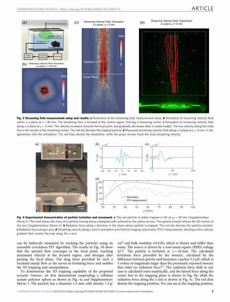
can be indirectly measured by tracking the particles using anensemble correlation PIV algorithm. The results in Fig. 3d showthat the upward flow converges to the focal point, reachingmaximum velocity at the focused region, and diverges afterpassing the focal plane. The drag force provided by such alocalized steady flow as the serves as levitating force and enablesthe 3D trapping and manipulation.
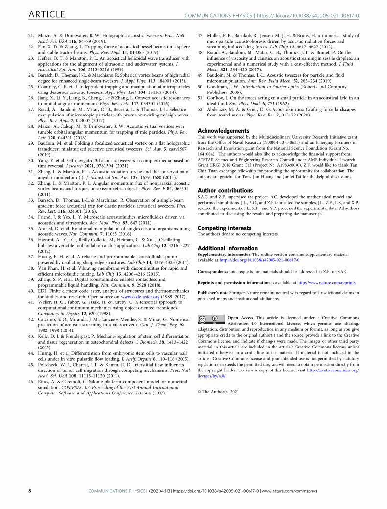
To demonstrate the 3D trapping capability of the proposedacoustic tweezer, we first demonstrate suspending a celluloseacetate polymer sphere as shown in Fig. 4a and SupplementaryMovie 1. The particle has a diameter 1.5 mm with density 1.3 g/
cm3 and bulk modulus 4.8 GPa, which is denser and stiffer thanwater. The source is driven by a root-mean square (RMS) voltage42 V. The particle is levitated at z= 42 mm. The calculatedlevitation force provided by the tweezer, calculated by thedifference between gravity and buoyancy, reaches 5.2 μN, which is3 orders of magnitude larger than the previously reported tweezerthat relies on radiation force33. The radiation force field in ourcase is calculated semi-analytically, and the lateral force along thecenter line in the trapping plane is shown in Fig. 4b, while theradiation force along the z axis is shown in Fig. 4c. The red dotsdenote the trapping position. We can see at the trapping position,
532 nm Fan-shaped Laser
Transducer & Lens
Deionized water with seeding particles
Recording camera
ComputerFunctionGenerator
PowerAmplifier
(a)
(b)
(c) (d) Streaming Velocity Field: Experimentx-z plane, y = 0 mm
Streaming Velocity Field: Simulationx-y plane, z = 30 mm
Streaming Velocity Field: Simulationx-z plane, y = 0 mm
Focal Plane
0
max
0
max
Particle
Fig. 3 Streaming field measurement setup and results. a Illustration of the streaming field measurement setup. b Simulation of streaming velocity fieldwithin x–y plane at z= 30mm. The streaming flow is focused in the central region, forming a streaming vortex. c Simulation of streaming velocity fieldalong x–z plane at y= 0mm. The velocity increases towards the focal point, and gradually decreases after a certain height. The low velocity along the nodeline is the results of the streaming vortex. The red dot denotes the trapped particle. dMeasured streaming velocity field along x–z plane at y= 0mm, in fairagreement with the simulation. The red lines denote the streamline, while the green arrows show the local streaming velocity.
Holder
Lens
Levitatedparticle
z0 = 42 mm
start end
xy
z
10
-30 -20 -10x / mm
-5
0
5
Fx (N
)
-7
0 10 20 30 100z / mm
-2
0
2F z
(N)
10-7
500
20 30 40 50 60 70 80 90 100z (mm)
0
20
40
60
80
Velo
city
(mm
/s)
SimulationPIV measurement
(a) (b) (c)
(d)
1 cm
Fig. 4 Experimental demonstration of particle levitation and movement. a The red particle is stably trapped in 3D at z0= 42mm (SupplementaryMovie 1). The inset shows the trace of a particle moving along a designed path outlined by the yellow arrows. The particle closely follows the 3D motion ofthe lens (Supplementary Movie 4). b Radiation force along x direction in the plane where particle is trapped. The red dot denotes the particle position.c Radiation force along z-axis. d Streaming velocity along z-axis in simulation and Particle imaging velocimetry (PIV) measurement, showing a flow velocitygradient that creates the trap along the z-axis.
COMMUNICATIONS PHYSICS | https://doi.org/10.1038/s42005-021-00617-0 ARTICLE
COMMUNICATIONS PHYSICS | (2021) 4:113 | https://doi.org/10.1038/s42005-021-00617-0 | www.nature.com/commsphys 5

the radiation force (0.02 μN) along the z-axis is much smallerthan the in-plane forces and the required levitation force,pointing downwards. This result confirms that all the levitationforce is provided by streaming. The streaming velocity along thez -axis in both simulation and PIV measurement are compared inFig. 4d, where good agreement in trend can be found despite non-negligible noise in PIV measurements. As a comparison, we havealso measured the free-fall speed of the particle in water tank bytracking the particle position in a video. The measured free-fallspeed is 83 mm/s, which is close to the streaming flow velocity atz= 42 mm from simulation and PIV measurement. The smalldiscrepancy is due to the slight change in field distribution, theexistence of PIV particles, and that the viscosity of water changesover time due to the dissolved gas, dust. Such a result alsoconfirms that the required levitation force is providing byacoustic streaming. The stiffness of the trap (k) was calculated asthe gradient of the force18. From Fig. 4b, it can be calculated thatthe lateral stiffness is kx= 0.52 mN/m. Since the PIV measure-ment is noisy, the vertical stiffness is estimated by fitting the datawith a rational curve, and calculate the stiffness of the curve,resulting in kz= 0.064 mN/m. It is worth noting that, since thelevitation is provided by the drag force in flow instead ofradiation force, the upward levitation force is less sensitive to theshape and material properties of the particle. As a demonstration,we have also shown the trapping of cylindrical particles withdiameter 1.3 mm and height 1.3 mm, and total weight 6 mg, asshown in Supplementary Movies 2 and 3. In this case, thecalculated levitation force reaches 41.8 μN. As a comparison, wedropped another particle outside the focused region, and it sinksquickly, as is shown in Supplementary Movie 3. Note that theapplied voltage on the transducer can be further increased forfaster streaming, while the first-order linear field shape ispreserved. Therefore, the tweezer can lift the heavier particlewithout sacrificing its in-plane trapping capability. We alsodemonstrate the ability to move the particle along a prescribedthree dimensional trajectory by scanning the source transducer,as shown in the inset of Fig. 4 and Supplementary Movie 4, wherethe trapped particle closely follows the designed path.
The hybrid acoustic tweezer relies on the balance of drag forceand gravity, Therefore, it is designed to work in the upwardorientation. Nevertheless, the trap stays stable even when thesetup is tilted. From the experimental results shown inSupplementary Movie 5, we can see that the tweezer can stablytrap the particle at a tilting angle as large as 21°.
Compared with the 3D trap demonstrated by Baresch et al.33
where the trapping force along z direction relies on the dipolemode in a sphere, levitating particles with drag in the streamingflow offers several advantages. First, it is able to levitate heavierparticles since the drag in streaming flow can provide largerupward force than using radiation forces. Second, it removes thedependence of trapping on the shape and material properties ofthe levitated particle. Third, the wave field is generated by a singletransducer and passive lens instead of the transducer array, whichprovides an inexpensive and reliable route for contact-freeparticle and fluid manipulation.
DiscussionRadiation force acoustic tweezers are a versatile platform forobject manipulation capable of handling a wide range of appli-cations in biology, chemistry, and medicine, owning to theirsimplicity and biocompatibility. However, for particle manip-ulation in the three dimensional space, there is a trade offbetween particle parameters and acoustic amplitude because ofthe stability issue and nonlinear streaming perturbation inducedby finite amplitude acoustic waves. Here we have described and
demonstrated a hybrid 3D single beam acoustic tweezer bycombining the radiation force and acoustic streaming. We showthat instead of being a nuisance, carefully designed acousticstreaming can be harnessed to help control particles in fluids andcreate a fully 3D trap. As a proof of concept, we have (i) designeda focused acoustic vortex lens that facilities acoustic vortextrapping and localized upward streaming flow simultaneously, (ii)verified the designed acoustic field and the correspondingstreaming field in both simulation and experiments, and (iii)demonstrated three dimensional trapping and manipulation ofparticles in fluid.
Compared with previously reported 3D acoustic tweezers influids, using acoustic streaming to defy gravity provides severalbenefits. First, since streaming tweezers rely on streaming draginstead of radiation force, they can accommodate a broader rangeof material properties and particle shapes, especially for largerand heavier particle cases where radiation force is not sufficient tolift the particle. For example, in our case, the levitation forceprovided by streaming is about 3 orders of magnitude larger thanpreviously reported radiation force tweezers, when scaled to thesame operating frequency. Second, the levitation force can betunable, so the same tweezer can adapt to a wide range of particlematerials by simply tuning the ultrasound amplitude, and thusoffers great versatility. Third, for biomedical applications wheretrapped particles are small, radiation force tweezers requirescaling up the frequency to keep a radius-to-wavelength ratiosufficiently large. However, sound absorption and non-linearityeffects become more significant for higher frequencies, so thatstreaming becomes unavoidable, making radiation tweezers lessreliable. In contrast, streaming tweezers are expected to takeadvantage of high frequencies since they naturally appear. Forexample, stem cell differentiation and migration has been provento be highly dependent on the strain and fluid flow. They havesignificant impact on bone regeneration, tissue growth, andembryonic development43–45. Such studies are typically con-ducted in microfluidic chambers. A non-contact device that holdthe cell and exert flow on it simultaneously may lead to inter-esting studies on cell differentiation. Fourth, for the radiationforce tweezers, interference between incident wave and reflectedwaves from the boundary may affect the trap. However, sincestreaming field is highly localized, changing the far-field bound-aries is not expected to dramatically change the flow dynamicsaround the trapping point.
There are also several limitations to the proposed tweezers.First, since the streaming flow velocity is not dropping drasticallydue to the inertia of water, the trapping stiffness in the axialdirection will be lower than the radial direction. This is a com-mon issue for single-sided three dimensional acoustic tweezers,and how to improve its axial resolution remains an open ques-tion. Second, the size of the trapped particle cannot be larger thanthe acoustic and streaming vortex. Otherwise, the scattering fromthe particle may affect the formation of streaming flow. For smallparticles, streaming will have larger influence on the particlebehavior than radiation forces, which may affect the stability inx–y plane. In this case, an acoustic tweezer with higher frequencyis suggested. Third, the trap relies on the balance betweenstreaming and gravity, so that it is expected to work only if it isorientated upwards. Fourth, due to the nonlinear nature ofacoustic streaming, the relation between the required levitationforce and applied acoustic amplitude is not linear. In addition, theprecise characterization of the levitation force requires couplingbetween the nonlinear acoustic field, fluid mechanics, and fluid-structure interaction, which adds difficulty for analytical calcu-lation and full simulation. Therefore, in the current setup,adaption to various particles is achieved by careful tuning of theinput amplitude. Other possible ways to tune the levitation force
ARTICLE COMMUNICATIONS PHYSICS | https://doi.org/10.1038/s42005-021-00617-0
6 COMMUNICATIONS PHYSICS | (2021) 4:113 | https://doi.org/10.1038/s42005-021-00617-0 | www.nature.com/commsphys

may include applying short pulsed signals with different dutycycle28. Nevertheless, we have shown that streaming offers anadditional degree of freedom for acoustic tweezers that cangreatly extend its versatility.
MethodsFabrication of the lens. The lens is fabricated with the standard PDMSmolding process. A negative mold was fabricated with stereolithography 3DPrinting. Part A and part B of Ecoflex 00-30 Silicone is mixed thoroughly by 1:1weight ratio, degassed with a vacuum chamber and then poured into the mold. Themold is then baked in an oven at 120 Celsius degrees for an hour for the silicone tocure. The lens is then separated from the mold and attached to thepiezoelectric patch.
Numerical simulations. The material thickness profile for the PDMS lens is cal-culated from the phase map for the holographic element17:
Tðr; θÞ ¼ T0 �Δϕðr; θÞkm � kh
ð1Þ
where T(r, θ) is the thickness of the lens pixel positioned at point with polarcoordinates (r, θ), T0 is the initial baseline thickness, kh and km are the wavenumbers in the hologram fabrication material and its surrounding medium, andΔϕ(r, θ) in our case is the phase map of the focused vortex sound wave source,calculated from the equation:
Δϕðr; θÞ ¼ km
ffiffiffiffiffiffiffiffiffiffiffiffiffiffi
r2 þ f 2q
� f
� �
þ θ ð2Þ
where (r, θ) are the pixel polar coordinates and f is the focal distance of the lens.The calculated thickness profile is then used to construct the 3D solid model (inSTEP format) of the lens using computer-aided design (CAD) software Salome8.346 with Python 2.7 interface. The STEP solid model of the lens is then ready for3D printing.
The acoustic finite element simulations were performed in Salome-MECA 2017CAE environment under Ubuntu 16 LTS system, using Code Aster 11.3 solver40 forthe numerical calculations of pressure acoustics in frequency domain and ParaVisplugin for post-processing. The simulations of acoustic streaming were performedin OpenFOAM v6 finite volume tool41 in two stages, using a slightly modifiedcompressible flow sonicLiquidFoam solver for the acoustic field simulation in timedomain, and icoFoam, incompressible steady-state solver for the simulation of thestreaming fluid flow itself. The streaming flow effect is achieved by adding anexternal force term into the second stage incompressible flow equations47:
F ¼ �ρ∂u∂t
� ρ0ðu � ∇Þu� �
ð3Þ
where u is the acoustic particle velocity and ρ is the compressible fluid densitycalculated during the first acoustic simulation stage, ρ0 is the equilibrium constantdensity, and ⟨⋅⟩ indicates the time-averaging of the term over a significant numberof iterations. The dynamic viscosity of water is set as μ= 0.0044 Pa ⋅ s, calculatedfrom the free-fall speed of the particle using Stokes’ Law. Note that a more precisemodeling of acoustic streaming has been developed recently48,49. The incidentacoustic pressure is estimated to be 35 kPa. In this study, we seek to qualitativelypredict the flow distribution with simulation, therefore, a simpler form is adopted.Even with such a simple form, we can still see a reasonable agreement betweensimulation and experiments.
Calculation of radiation forces. The radiation force on the particle is calculatedsemi-analytically. First, the entire acoustic pressure and velocity field is calculatedusing angular spectrum analysis (ASA) method50. Then for a specific particle, theGor’kov potential field U can be calculated as51:
U ¼ 2πR3 hp2i3ρ0c
20f 1 �
ρ0hv2i2
f 2
� �
ð4Þ
where f 1 ¼ 1� ρ0c20
ρpc2p, f 2 ¼
2ðρp�ρ0Þ2ρpþρ0
are constants that characterize monopole and
dipole responses, respectively. The subscript p denotes the particle. The radiationforce can then be estimated using F=−∇U. Note here that here we used simplemodel to qualitatively calculate the radiation forces. More precise models have beendeveloped to take into account the non-conservative forces and shear modulus ofthe particle33,52. We would also like to note that the trapped particle in our casedoes not only subject to radiation forces, but also affected by the nontrivial particle-fluid interaction. Such a feature makes it even more challenging for accurate the-oretical predictions, which could be an interesting future direction.
Acoustic field measurement and particle imaging velocimetry. The measure-ment was performed in a 40-gallon water tank. For the measurement of the linearacoustic field, the computer-controlled function generator (RIGOL DG4102)generates a Gaussian-modulated pulse centered at 500 kHz. The signal is amplifiedby ENI 2100L RF power amplifier and drives the PZT disk. A hydrophone (ONDA
HNR-0500) is attached to a 3D scanning stage to scan the field. The output signalfrom the hydrophone is recorded by AlazarTech ATS 9440 waveform digitizer at asample rate 125MS/s. The signal at each scanned position is averaged over 1024measurements to eliminate noises. Then Fourier transform is performed to extractthe amplitude and phase for 500 kHz to generate the field map.
For the measurement of the flow field, we adopted particle image velocimetry(PIV). Polyamide seeding particles with density 1.03 g/cm3 and mean size 60 μmare dispersed in water. A 532 nm laser line generator emits a fan-shaped beam andthe light plane is aligned with x–z plane. The flow is recorded with the slow motionmode of a cellphone camera. The video is processed with PIVlab, an open sourcetoolbox in MATLAB. Since the particle is sparsely dispersed in the fluid, theensemble correlation PIV algorithm is adopted, where 2000 frames are used as anensemble.
Data availabilityAll data needed to evaluate the conclusions in the paper are presented in the paper.Additional data related to this paper may be requested from the authors.
Code availabilityThe codes that support the findings of this study are available from the correspondingauthors upon reasonable request.
Received: 12 February 2021; Accepted: 21 April 2021;
References1. Baresch, D., Thomas, J.-L. & Marchiano, R. Three-dimensional acoustic
radiation force on an arbitrarily located elastic sphere. J. Acoustical Soc. Am.133, 25–36 (2013).
2. Ozcelik, A. et al. Acoustic tweezers for the life sciences. Nat. Methods 15,1021–1028 (2018).
3. Shi, J. et al. Acoustic tweezers: patterning cells and microparticles usingstanding surface acoustic waves (ssaw). Lab Chip 9, 2890–2895 (2009).
4. Tran, S., Marmottant, P. & Thibault, P. Fast acoustic tweezers for the two-dimensional manipulation of individual particles in microfluidic channels.Appl. Phys. Lett. 101, 114103 (2012).
5. Ding, X. et al. On-chip manipulation of single microparticles, cells, andorganisms using surface acoustic waves. Proc. Natl Acad. Sci. USA 109,11105–11109 (2012).
6. Foresti, D., Nabavi, M., Klingauf, M., Ferrari, A. & Poulikakos, D.Acoustophoretic contactless transport and handling of matter in air. Proc. NatlAcad. Sci. USA 110, 12549–12554 (2013).
7. Ding, X. et al. Cell separation using tilted-angle standing surface acousticwaves. Proc. Natl Acad. Sci. USA 111, 12992–12997 (2014).
8. Foresti, D. & Poulikakos, D. Acoustophoretic contactless elevation, orbitaltransport and spinning of matter in air. Phys. Rev. Lett. 112, 024301 (2014).
9. Collins, D. J. et al. Two-dimensional single-cell patterning with one cell perwell driven by surface acoustic waves. Nat. Commun. 6, 8686 (2015).
10. Augustsson, P., Karlsen, J. T., Su, H.-W., Bruus, H. & Voldman, J. Iso-acousticfocusing of cells for size-insensitive acousto-mechanical phenotyping. Nat.Commun. 7, 11556 (2016).
11. Collins, D. J. et al. Acoustic tweezers via sub–time-of-flight regime surfaceacoustic waves. Sci. Adv. 2, e1600089 (2016).
12. Guo, F. et al. Three-dimensional manipulation of single cells using surfaceacoustic waves. Proc. Natl Acad. Sci. USA 113, 1522–1527 (2016).
13. Ng, J. W., Devendran, C. & Neild, A. Acoustic tweezing of particles usingdecaying opposing travelling surface acoustic waves (dotsaw). Lab Chip 17,3489–3497 (2017).
14. Tian, Z. et al. Wave number–spiral acoustic tweezers for dynamic andreconfigurable manipulation of particles and cells. Sci. Adv. 5, eaau6062(2019).
15. Démoré, C. E. et al. Acoustic tractor beam. Phys. Rev. Lett. 112, 174302 (2014).16. Marzo, A. et al. Holographic acoustic elements for manipulation of levitated
objects. Nat. Commun. 6, 8661 (2015).17. Melde, K., Mark, A. G., Qiu, T. & Fischer, P. Holograms for acoustics. Nature
537, 518 (2016).18. Franklin, A., Marzo, A., Malkin, R. & Drinkwater, B. Three-dimensional
ultrasonic trapping of micro-particles in water with a simple and compacttwo-element transducer. Appl. Phys. Lett. 111, 094101 (2017).
19. Memoli, G. et al. Metamaterial bricks and quantization of meta-surfaces. Nat.Commun. 8, 1–8 (2017).
20. Prisbrey, M. & Raeymaekers, B. Ultrasound noncontact particle manipulationof three-dimensional dynamic user-specified patterns of particles in air. Phys.Rev. Appl. 10, 034066 (2018).
COMMUNICATIONS PHYSICS | https://doi.org/10.1038/s42005-021-00617-0 ARTICLE
COMMUNICATIONS PHYSICS | (2021) 4:113 | https://doi.org/10.1038/s42005-021-00617-0 | www.nature.com/commsphys 7
21. Marzo, A. & Drinkwater, B. W. Holographic acoustic tweezers. Proc. NatlAcad. Sci. USA 116, 84–89 (2019).
22. Fan, X.-D. & Zhang, L. Trapping force of acoustical bessel beams on a sphereand stable tractor beams. Phys. Rev. Appl. 11, 014055 (2019).
23. Hefner, B. T. & Marston, P. L. An acoustical helicoidal wave transducer withapplications for the alignment of ultrasonic and underwater systems. J.Acoustical Soc. Am. 106, 3313–3316 (1999).
24. Baresch, D., Thomas, J.-L. & Marchiano, R. Spherical vortex beams of high radialdegree for enhanced single-beam tweezers. J. Appl. Phys. 113, 184901 (2013).
25. Courtney, C. R. et al. Independent trapping and manipulation of microparticlesusing dexterous acoustic tweezers. Appl. Phys. Lett. 104, 154103 (2014).
26. Jiang, X., Li, Y., Liang, B., Cheng, J.-c & Zhang, L. Convert acoustic resonancesto orbital angular momentum. Phys. Rev. Lett. 117, 034301 (2016).
27. Riaud, A., Baudoin, M., Matar, O. B., Becerra, L. & Thomas, J.-L. Selectivemanipulation of microscopic particles with precursor swirling rayleigh waves.Phys. Rev. Appl. 7, 024007 (2017).
28. Marzo, A., Caleap, M. & Drinkwater, B. W. Acoustic virtual vortices withtunable orbital angular momentum for trapping of mie particles. Phys. Rev.Lett. 120, 044301 (2018).
29. Baudoin, M. et al. Folding a focalized acoustical vortex on a flat holographictransducer: miniaturized selective acoustical tweezers. Sci. Adv. 5, eaav1967(2019).
30. Yang, Y. et al. Self-navigated 3d acoustic tweezers in complex media based ontime reversal. Research 2021, 9781394 (2021).
31. Zhang, L. & Marston, P. L. Acoustic radiation torque and the conservation ofangular momentum (l). J. Acoustical Soc. Am. 129, 1679–1680 (2011).
32. Zhang, L. & Marston, P. L. Angular momentum flux of nonparaxial acousticvortex beams and torques on axisymmetric objects. Phys. Rev. E 84, 065601(2011).
33. Baresch, D., Thomas, J.-L. & Marchiano, R. Observation of a single-beamgradient force acoustical trap for elastic particles: acoustical tweezers. Phys.Rev. Lett. 116, 024301 (2016).
34. Friend, J. & Yeo, L. Y. Microscale acoustofluidics: microfluidics driven viaacoustics and ultrasonics. Rev. Mod. Phys. 83, 647 (2011).
35. Ahmed, D. et al. Rotational manipulation of single cells and organisms usingacoustic waves. Nat. Commun. 7, 11085 (2016).
36. Hashmi, A., Yu, G., Reilly-Collette, M., Heiman, G. & Xu, J. Oscillatingbubbles: a versatile tool for lab on a chip applications. Lab Chip 12, 4216–4227(2012).
37. Huang, P.-H. et al. A reliable and programmable acoustofluidic pumppowered by oscillating sharp-edge structures. Lab Chip 14, 4319–4323 (2014).
38. Van Phan, H. et al. Vibrating membrane with discontinuities for rapid andefficient microfluidic mixing. Lab Chip 15, 4206–4216 (2015).
39. Zhang, S. P. et al. Digital acoustofluidics enables contactless andprogrammable liquid handling. Nat. Commun. 9, 2928 (2018).
40. EDF. Finite element code_aster, analysis of structures and thermomechanicsfor studies and research. Open source on www.code-aster.org (1989–2017).
41. Weller, H. G., Tabor, G., Jasak, H. & Fureby, C. A tensorial approach tocomputational continuum mechanics using object-oriented techniques.Computers in Physics 12, 620 (1998).
42. Catarino, S. O., Miranda, J. M., Lanceros-Mendez, S. & Minas, G. Numericalprediction of acoustic streaming in a microcuvette. Can. J. Chem. Eng. 921988–1998 (2014).
43. Kelly, D. J. & Prendergast, P. Mechano-regulation of stem cell differentiationand tissue regeneration in osteochondral defects. J. Biomech. 38, 1413–1422(2005).
44. Huang, H. et al. Differentiation from embryonic stem cells to vascular wallcells under in vitro pulsatile flow loading. J. Artif. Organs 8, 110–118 (2005).
45. Polacheck, W. J., Charest, J. L. & Kamm, R. D. Interstitial flow influencesdirection of tumor cell migration through competing mechanisms. Proc. NatlAcad. Sci. USA 108, 11115–11120 (2011).
46. Ribes, A. & Caremoli, C. Salomé platform component model for numericalsimulation. COMPSAC 07: Proceeding of the 31st Annual InternationalComputer Software and Applications Conference 553–564 (2007).
47. Muller, P. B., Barnkob, R., Jensen, M. J. H. & Bruus, H. A numerical study ofmicroparticle acoustophoresis driven by acoustic radiation forces andstreaming-induced drag forces. Lab Chip 12, 4617–4627 (2012).
48. Riaud, A., Baudoin, M., Matar, O. B., Thomas, J.-L. & Brunet, P. On theinfluence of viscosity and caustics on acoustic streaming in sessile droplets: anexperimental and a numerical study with a cost-effective method. J. FluidMech. 821, 384–420 (2017).
49. Baudoin, M. & Thomas, J.-L. Acoustic tweezers for particle and fluidmicromanipulation. Ann. Rev. Fluid Mech. 52, 205–234 (2019).
50. Goodman, J. W. Introduction to Fourier optics (Roberts and CompanyPublishers, 2005).
51. Gor’kov, L. On the forces acting on a small particle in an acoustical field in anideal fluid. Sov. Phys. Dokl. 6, 773 (1962).
52. Abdelaziz, M. A. & Grier, D. G. Acoustokinetics: Crafting force landscapesfrom sound waves. Phys. Rev. Res. 2, 013172 (2020).
AcknowledgementsThis work was supported by the Multidisciplinary University Research Initiative grantfrom the Office of Naval Research (N00014-13-1-0631) and an Emerging Frontiers inResearch and Innovation grant from the National Science Foundation (Grant No.1641084). The authors would also like to acknowledge the financial support fromA*STAR Science and Engineering Research Council under AME Individual ResearchGrant (IRG) 2018 Grant Call (Project No. A1983c0030). Z.F. would like to thank TanChin Tuan exchange fellowship for providing the opportunity for collaboration. Theauthors are grateful for Tony Jun Huang and Junfei Tai for the helpful discussions.
Author contributionsS.A.C. and Z.F. supervised the project. A.C. developed the mathematical model andperformed simulations. J.L., A.C., and Z.F. fabricated the samples, J.L., Z.F., L.S., and X.P.realized the experiments. J.L., X.P., and Y.P. processed the experimental data. All authorscontributed to discussing the results and preparing the manuscript.
Competing interestsThe authors declare no competing interests.
Additional informationSupplementary information The online version contains supplementary materialavailable at https://doi.org/10.1038/s42005-021-00617-0.
Correspondence and requests for materials should be addressed to Z.F. or S.A.C.
Reprints and permission information is available at http://www.nature.com/reprints
Publisher’s note Springer Nature remains neutral with regard to jurisdictional claims inpublished maps and institutional affiliations.
Open Access This article is licensed under a Creative CommonsAttribution 4.0 International License, which permits use, sharing,
adaptation, distribution and reproduction in any medium or format, as long as you giveappropriate credit to the original author(s) and the source, provide a link to the CreativeCommons license, and indicate if changes were made. The images or other third partymaterial in this article are included in the article’s Creative Commons license, unlessindicated otherwise in a credit line to the material. If material is not included in thearticle’s Creative Commons license and your intended use is not permitted by statutoryregulation or exceeds the permitted use, you will need to obtain permission directly fromthe copyright holder. To view a copy of this license, visit http://creativecommons.org/licenses/by/4.0/.
© The Author(s) 2021
ARTICLE COMMUNICATIONS PHYSICS | https://doi.org/10.1038/s42005-021-00617-0
8 COMMUNICATIONS PHYSICS | (2021) 4:113 | https://doi.org/10.1038/s42005-021-00617-0 | www.nature.com/commsphys