THÈSE - Paul Sabatierthesesups.ups-tlse.fr/2356/1/2014TOU30032.pdfHong Luyen, Béatrice MOUKARZE,...
131
T T H H È È S S E E En vue de l'obtention du DOCTORAT DE L’UNIVERSITÉ DE TOULOUSE Délivré par L'UNIVERSITE DE TOULOUSE III- PAUL SABATIER Discipline ou spécialité : Chimie-Biologie-Santé JURY Jean Pierre SOUCHARD, Professeur, Université Paul Sabatier, Toulouse Patrick ABGRALL, Chercheur, Formulaction, Toulouse Catherine PERRIN, Professeur, Université de Montpellier 1, Montpellier Xavier COQUERET, Professeur, ICMR, Reims Anne-Marie GUE, Directrice de Recherche, LAAS, Toulouse Jan SUDOR, Maître de Conférences, Université Paul Sabatier, Toulouse Ecole doctorale : Sciences de la Matière Unité de recherche : Pharmacochimie et pharmacologie pour le développement, PHARMA-DEV, UMR 152 IRD-UPS Directeur(s) de Thèse : Jan SUDOR Rapporteurs : Catherine PERRIN/ Xavier COQUERET Présentée et soutenue par VU Thi Thu Le 24 Février 2014 Titre : Study of nano-engineered solid/liquid interfaces based on polymer brushes and biomimetic multifunctional glue
Transcript of THÈSE - Paul Sabatierthesesups.ups-tlse.fr/2356/1/2014TOU30032.pdfHong Luyen, Béatrice MOUKARZE,...

TTHHÈÈSSEE
En vue de l'obtention du
DDOOCCTTOORRAATT DDEE LL’’UUNNIIVVEERRSSIITTÉÉ DDEE TTOOUULLOOUUSSEE
Délivré par L'UNIVERSITE DE TOULOUSE III- PAUL SABATIER
Discipline ou spécialité : Chimie-Biologie-Santé
JURY
Jean Pierre SOUCHARD, Professeur, Université Paul Sabatier, Toulouse Patrick ABGRALL, Chercheur, Formulaction, Toulouse
Catherine PERRIN, Professeur, Université de Montpellier 1, Montpellier Xavier COQUERET, Professeur, ICMR, Reims
Anne-Marie GUE, Directrice de Recherche, LAAS, Toulouse Jan SUDOR, Maître de Conférences, Université Paul Sabatier, Toulouse
Ecole doctorale : Sciences de la Matière
Unité de recherche : Pharmacochimie et pharmacologie pour le développement, PHARMA-DEV, UMR 152 IRD-UPS
Directeur(s) de Thèse : Jan SUDOR
Rapporteurs : Catherine PERRIN/ Xavier COQUERET
Présentée et soutenue par VU Thi Thu Le 24 Février 2014
Titre : Study of nano-engineered solid/liquid interfaces based on polymer brushes and
biomimetic multifunctional glue

i
Remerciements
Le travail présenté dans ce manuscrit a été réalisé au Laboratoire «Pharmacochimie et
Pharmacologie pour le Développement » (PHARMA-DEV, UMR 152-IRD), Toulouse,
France.
Je remercie très sincèrement Monsieur le docteur Jan SUDOR, mon directeur de thèse,
pour m’avoir encadré et suivi mes travaux avec rigueur et efficacité pendant ces trois
années, dans une ambiance toujours conviviale.
Je souhaite également remercier Madame le Professeur Françoise NEPVEU, chef de
l’équipe RED-STRESS, pour m’avoir accueillie dans son équipe de recherche.
Je désire remercier Madame la Directrice de Recherche Marie-Anne GUE du Laboratoire
d’Analyse et d’Architecture des Systèmes (LAAS) de Toulouse d’avoir soutenue à
travailler dans son équipe.
Je tiens également à remercier le docteur Ennaji NAJAHI d’avoir partagé ses
connaissances en synthèse des polymères avec moi.
Je remercie Marc FOUET pour m’avoir aidé à fabriquer des dispositifs micro-fluidiques en
PDMS au LAAS.
Je remercie sincèrement les chercheurs Benjamin REIG et Jean Baptise DOUCET, Thi Ty
Mai DINH au LAAS pour m’avoir aidé à travailler dans la salle blanche.
Un grand merci également aux personnels administratifs du laboratoire. Je pense tout
particulièrement à Eliane PELISSOU, Marie Agnes BELLIERES et Franck MARIE-
SAINTE pour leur sympathie et leur gentillesse.
Bien entendu, je remercie tous les membres, passés ou présents, du laboratoire qui m’ont
permis de travailler dans une ambiance toujours sympathique: Fabrice COLLIN, Karine
REYBIER, NGUYEN Thi Hoang Yen, Pierre PERIO, Laure-Estelle CASSAGNES,

ii
Clémence CHEIGNON, Nambinina RAKOTOARIVELO, Armelle MONTROSE, LE
Hong Luyen, Béatrice MOUKARZE, Aida CHAKER, Hany IBRAHIM, Rémi
MANCZAK, Nehal IBRAHIM, Cynthia GIRARDI.
Enfin un grand merci à mes parents et mon frère, ainsi que toute ma famille et mes amis,
pour leur soutiens et les encouragements qu’ils m’ont apportés.

iii
Acknowledgements
I would like to express my sincere gratitude to my supervisor, Dr. Jan SUDOR, for his
support and guidance. I truly appreciated his leadership, inspiration and encouragement in
every step during my PhD study, giving me the trust and freedom to carry out the research.
I am truly grateful that Professor Françoise NEPVEU, head of RED-STRESS group, did
welcome me in her research group.
I would also like to express my sincere gratitude to Dr. Anne-Marie GUE, who has
graciously offered permission to use the lab and provided so many helpful and detailed
comments on micro-fluidic devices as well as on surface characterization.
Deep thanks must to be given to Dr. Ennaji NAJAHI for his kind assistance with numerous
experiments and his helpful discussions and suggestions on synthesis of polymer.
I also want to thank Marc FOUET for his kind help and assistance in fabrication of PDMS
based micro-fluidic devices.
I need to thank Benjamin REIG, Jean Baptise DOUCET, Thi Ty Mai DINH at LAAS for
help and training in clean room.
I would like to express my gratitude to the business office personnel, Eliane PELISSOU,
Marie Agnes BELLIERES and Franck MARIE-SAINTE for all their help through all these
years.
I would also like to extend my appreciation to other past and current members of
PHARMA-DEV for being a friendly laboratory and providing helpful insight, including
Fabrice COLLIN, Karine REYBIER, NGUYEN Thi Hoang Yen, Pierre PERIO, Laure-
Estelle CASSAGNES, Clémence CHEIGNON, Nambinina RAKOTOARIVELO, Armelle
MONTROSE, LE Hong Luyen, Béatrice MOUKARZE, Aida CHAKER, Hany IBRAHIM,
Rémi MANCZAK, Nehal IBRAHIM, Cynthia GIRARDI and many others.

iv
Lastly, I would like to thank my family, my parents and my brother for your unconditional
love, support, courage, dedication and selflessness. I would like to dedicate this thesis to
you, who I love the most.

v
DEDICATION
This thesis is dedicated to my entire loving and supportive family.

vi
Table of contents
List of abbreviations
List of figures
List of schemes
List of tables
Introduction
Motivation and aims
Thesis outline
Chapter 1: Literature review
1.1. Solid / liquid interfaces and microfluidic devices
1.1.1. Introduction ................................................................................................................ 13
1.1.2. Omnipresence of solid / liquid interfaces (SLIs) ....................................................... 14
1.1.3. Control of properties of SLIs ..................................................................................... 17
1.1.3.1. Self-assembled monolayers (SAMs) ................................................................. 17
1.1.3.2. End-tethered polymers at SLIs .......................................................................... 19
1.1.3.3. Adsorbed polymer layers .................................................................................. 20
1.1.4. A microchannel - scaling laws (importance of Surface to Volume ratio) ................ 23
1.1.4.1. Scaling laws in down-scaling: the predominance of surface forces on volume
forces ............................................................................................................................... 23
1.1.4.2. Dimensionless numbers in microfluidics ........................................................... 24
1.1.4.3. Adsorption phenomena ...................................................................................... 25
1.1.5. Microfluidic devices (lab-on-chips) .......................................................................... 26
1.1.5.1. Commercerlization of microfluidic devices ....................................................... 26
1.1.5.2. Advantages of miniaturization and integration .................................................. 26
1.1.5.3. Microfabrication of microfluidic devices .......................................................... 27
1.1.6. Conclusions ............................................................................................................... 34

vii
1.2. Mussel inspired surface chemistry
1.2.1.Introduction ................................................................................................................. 40
1.2.2. Principles of mussel inspired surface chemistry ....................................................... 41
1.2.2.1. Mussel adhesion ................................................................................................ 41
1.2.2.2. Oxidation of dopamine ....................................................................................... 41
1.2.2.3. Deposition regime of DOPA-type films ........................................................... 44
1.2.3. Properties of DOPA ................................................................................................... 45
1.2.4. Effect of oxidation conditions on formation of DOPA-type films ............................ 46
1.2.5. Applications of mussel inspired surface chemistry ................................................... 47
1.2.6. Conclusions ............................................................................................................... 50
Chapter 2: Amine terminated polymers
2.1. Introduction ....................................................................................................................... 55
2.2. Materials ............................................................................................................................ 56
2.3. Experiments ....................................................................................................................... 57
2.3.1. Mechanism of chain transfer radical polymerization................................................. 57
2.3.2. Procedure ................................................................................................................... 58
2.4. Results and discussions ..................................................................................................... 59
2.4.1. Fourier transform infrared spectroscopy (FTIR) ....................................................... 59
2.4.2. Nuclear magnetic resonance (NMR) ......................................................................... 59
2.4.3. Matrix-assisted laser desorption/ionization – Time of flight (MALDI-TOF) ........... 63
2.4.4. Size exclusion chromatography (SEC) ...................................................................... 64
2.4.5. Fluorescence labelling ............................................................................................... 66
2.4.6. DCC/HOBT mediated amidation............................................................................... 68
2.5. Conclusions ....................................................................................................................... 70
Chapter 3: Optimization of oxidation of dopamine
3.1. Introduction ....................................................................................................................... 73
3.2. Materials ............................................................................................................................ 74
3.3. Experiments ................................................................................................................................. 75
3.4. Characterization ................................................................................................................ 76
3.4.1. UV-Vis absorption ..................................................................................................... 76
3.4.2. Water contact angle (WCA) ....................................................................................... 76
viii
3.4.3. Atomic force microscopy (AFM) .............................................................................. 76
3.4.4. Nano analyser ............................................................................................................ 77
3.5. Results and discussions ..................................................................................................... 78
3.5.1. Intrinsic huge aggregates and high roughness of DOPA films .................................. 78
3.5.2. Effect of oxidation conditions on oxidation kinetics, deposition kinetics and
surface morphology ............................................................................................................. 79
3.5.2.1. Effect of oxidation conditions on oxidation kinetics ......................................... 80
3.5.2.2. Effect of oxidation conditions on deposition kinetics ........................................ 81
3.5.2.3. Effect of oxidation conditions on surface morphology ...................................... 83
3.5.3. Versatility of DOPA film ........................................................................................... 84
3.6. Conclusions ....................................................................................................................... 86
Chapter 4: Monitoring wettability of heterogeneous material surfaces in fluidic
devices
Introduction ............................................................................................................................. 89
A new and easy surface functionalization technology for monitoring wettability in
heterogeneous nano- and micro-fluidic devices (Published article) ....................................... 90
Supporting information ......................................................................................................... 103
Conclusions
Future outlook
Résumé (en français)

ix
List of abbreviations
AAO Anodic Aluminum Oxide
AFM Atomic Force Microscopy
AM Acrylamide
AmPAM Amine terminated PolyAcrylamide
AmPNIPAM Amine terminated Poly(N-Isopropylacrylamide)
CE Capillary Electrophoresis
CTA Chain Transfer Atom
CTRP Chain Transfer Radical Polymerization
CV Cyclic Voltammetry
DCC N,N’-DicyclohexylCarbodiimide
DHI 5,6-DiHydroxylIndole
DOP Dopamine
DOPA Polydopamine/pseudo-dopamine/dopamine-melanin
FITC Fluorescein isothiocyanate
EOF Electro-Osmotic Flow
FTIR Fourier Transform Infrared Spectroscopy
HOBT 1-Hydroxy-benzotriazol
iCMBAs injectable Citrate based Mussel inspired BioAdhesives
KPS Potassium Persulfate
LOCs Lab-on-chips
MALDI-TOF Matrix-assisted laser desorption/ionization – Time of Flight
MiSC Mussel inspired Surface Chemistry
MW Molecular Weight
NIPAM N-IsoPropyl-Acrylamide
NMR Nuclear Magnetic Resonance
PAM PolyAcrylAmide
PC PolyCarbonate
PDMS Poly(DiMethylSiloxane)
PEG Poly(EthyleneGlycol)
PEO (=PEG) PolyEthylene Oxide
pI Isoelectric point
PL Poly(Lactide)

x
PMMA Poly(MethylMethacrylate)
PNIPAM Poly(N-IsoPropylAcrylamide)
pSBMA Poly(SulfoBetaine MethAcrylate)
PU PolyUrethane
SAMs Self-Assembled Monolayers
SEC Size Exclusion Chromatography
TEMED N,N,N',N'-TetraMethylEthyleneDiamine
WCA Water Contact Angle
μTAS micro total analysis system

xi
List of figures
Figure 1.1. Illustration of a cell-membrane .............................................................................. 15
Figure 1.2. Animation of scaling laws at nano- / micro-scale .................................................. 16
Figure 1.3. Illustration of self-assembled monolayers ............................................................. 18
Figure 1.4. Adaptable approaches to grafting polymer brushes on a wide range of materials. 19
Figure 1.5. Adsorption and Depletion of polymer chains on surface ....................................... 21
Figure 1.6. Example of adsorption of polyelectrolytes on surfaces ......................................... 23
Figure 1.7. Scaling laws in a microchannel .............................................................................. 24
Figure 1.1. Illustration of Wet etching of glass ....................................................................... 30
Figure 1.2. Illustration of Molding process of PDMS microchannels .................................... 32
Figure 1.3. Illustration of Casting process ............................................................................... 32
Figure 2.1. 1H NMR spectra of PNIPAMc and PAMc ............................................................. 60
Figure 2.2. 1H NMR spectra of PAM synthesized at different monomer concentrations and
different initiator concentrations .............................................................................................. 61
Figure 2.3. 1H NMR spectra of PNIPAM synthesized at different monomer concentrations
and different initiator concentrations ........................................................................................ 61
Figure 2.4. 13C NMR spectra of PAM synthesized at different monomer concentrations and
different initiator concentrations .............................................................................................. 62
Figure 2.5. 13C NMR spectra of PNIPAM synthesized at different monomer concentrations
and different initiator concentrations ........................................................................................ 62
Figure 2.6. MALDI-TOF of amine terminated PNIPAM ...................................................... 63
Figure 2.7. FITC conjugated polyacrylamide ........................................................................... 67
Figure 2.8. 13C NMR spectra of unmodified PNIPAM and PNIPAM modified with acrylic
acid ........................................................................................................................................... 69
Figure 3.1. AFM measurements of DOPA film deposited in sealed reactor ............................ 79
Figure 3.2. Evolution of DOPA film on silicon oxide wafer in various oxidation conditions . 81
Figure 3.3. Deposition kinetics analysis of DOPA films in various oxidation conditions ...... 82
Figure 3.4. AFM topography of DOPA on silicon oxide wafer in various oxidation
conditions ................................................................................................................................. 83
Figure 3.5. Wettability of DOPA film on various substrates .................................................. 84

xii
List of schemes
Scheme 1.1. Oxidation mechanism of dopamine ..................................................................... 42
Scheme 1.2. Strong non-covalent bond in DOPA from hydrogen bond .................................. 43
Scheme 1.3. Mix of non-covalent bond and covalent bonding in DOPA ................................ 43
Scheme 1.4. Attachment of DOPA to surface by chemical affinity ......................................... 44
Scheme 1 5. Attachment of DOPA to surface by adsorption of catechol radicals ................... 45
Scheme 2.1. Mechanism of chain transfer telomerization mechanism .................................... 57
Scheme 2.2. Conjugation of amine terminated polymer with FITC ........................................ 67
Scheme 2.3. DCC/HOBt mediated amidation between amino terminated PNIPAM and
acrylic acid ................................................................................................................................ 69
List of tables
Table 2.1. List of synthesized polymers ................................................................................... 58
Table 2.2. Molecular weights (determined from SEC) of synthesized polymers..................... 65

xiii
Introduction
Motivation and aims
The objective of the thesis was to develop a surface nonspecific technology for
modifying solid/liquid interfaces of virtually any material used in the fabrication of
multicomponent nano- and micro- fluidic devices. Our objective was accomplished by
using and optimizing mussel inspired surface chemistry based on sticky DOPA films.
This new technology offered an opportunity for the homogenization of surface energy of
all studied materials.
Lab-on-chips (LOCs), also called “micro total analysis systems (µTAS)”, is a newly
emerging field that represents a breakthrough in biomedical analysis and diagnosis. The
aim of this field is to develop miniaturized and integrated fluidic devices that permit to
decrease the time and cost of an analysis and that operate in an automated manner. From
historical point of view, LOCs emerged from efforts to control liquid flow at subnanoliter
scale in the early 1990s. Over the last twenty-five years, hundreds of microfluidic research
groups and tens of microfluidic related companies have been established. At present, we
can find some commercial products based on LOCs, such as iSTAT blood analyzer from
Abbott Point-of-Care, glucose meter from Bayer Healthcare, DNA and peptide analyzer
from Agilent.
To fabricate complex microfluidic devices, various solid materials, spanning from
silicon, glass and plastics can be employed. The material of choice is often governed by
the specific requirements of a given application while the price of the device can also play
a crucial role. It was demonstrated that the cost of a microfluidic device can be
dramatically reduced by applying hybrid technology in which silicon-based actuators are
incorporated into non-expensive polymeric materials. On the other hand, it is well known
that decreasing the size of any fluidic device leads invariably into increase of the surface-
to- volume ratio. This often imposes the necessity to perform laborious, chemical or
physical tailoring of the surfaces, especially in the micro- and nano-fluidic devices
dedicated to biological applications. In general, surface modification approaches are
developed case-by-case. They depend only on the properties of the modified materials and

xiv
tethering molecules. The methods most commonly employed for the functional
modification of solid surfaces include the formation of self-assembled monolayers (SAMs)
on metals, silane-based chemistry on silicon and glass substrates and polyelectrolyte layer-
by-layer assembly on charged surfaces. It is clear that with these state-of-the-art surface
modification approaches, it would be impossible to homogenize the surface properties in
multicomponent or hybrid fluidic devices, integrating silicon, glass, metals, photoresists
(e.g., SU8) and elastomers (e.g., polydimethoxysilane, PDMS) together.
The mussel adhesion to any solid surface in wet condition has now become the
inspiration for the development of a universal surface functionalization approach, namely
mussel inspired surface chemistry (MiSC). To cling to rocks during high tide, mussel
secretes adhesive proteins that harden into solid, water-resistant glue. These biomimetic
glues allow us to tailor the physic-chemical properties of almost any solid / liquid interface
in a desired way.
In this study, we present a substrate-independent route for grafting end-functionalized
polyacrylamide chains onto any solid surfaces through mussel inspired chemistry.
Dopamine spontaneously oxidizes, under alkaline conditions, and forms highly reactive
products that further polymerize and self-organize. This leads to a formation of thin-layer
coating (DOPA films) that can be additionally modified with various molecules of interest.
It has been shown in the literature that amines, thiols and carboxyl groups react with
DOPA films. We have synthesized a variety of amino-terminated polyacrylamide and
polyacrylamide derivative chains of different molecular weights. The polyacrylamide
chains were end-tethered on different materials via a one-pot approach and the modified
surfaces were thoroughly characterized.
The specific objectives of this study are:
- To synthesize amino-terminated polyacrylamide-based chains (PAM, PNIPAM) with
variable molecular weights
- To characterize structural properties of synthesized polymers and to determine their
molecular weights
- To optimize oxidation conditions of dopamine in order to achieve low-roughness DOPA-
type thin films

xv
- To graft synthesized polymers to flat surfaces made of different materials using one-pot
mussel inspired surface chemistry at optimized conditions
- To demonstrate the possibility to obtain non-fouling surfaces inside microfluidic devices
Thesis outline
This thesis is organized into four chapters and a general conclusion.
In the first chapter, the literature overview on the solid / liquid interfaces (SLIs) and
the mussel inspired surface chemistry (MiSC) is depicted. First we describe the
omnipresence of solid / liquid interfaces and their growing importance in downscaling, i.e.,
in micro- and nano- fluidic devices. The state-of-the-art of the modification of SLIs is
described here as well and it is shown that the surface chemistry is highly substrate-
dependent. Consequently, we give a general overview on the mussel inspired surface
chemistry and we describe the mechanism of this approach. It is shown that the MiSC is
substrate-independent and that it can be utilized as a universal method for the
homogenization of surface energy in microfluidic channels built from various materials.
The second chapter of the thesis describes the synthesis of the amine terminated
polyacrylamide and poly(N-Isopropylacrylamide) by the chain transfer radical
polymerization. The experimental conditions of synthesis and detailed characterization of
the synthesized polymers by Fourier Transform Infrared Spectroscopy (FTIR), Nuclear
Magnetic Resonance (NMR), Size Exclusion Chromatography (SEC), Matrix-assisted laser
desorption/ionization Time-of-Flight (MALDI-TOF) mass spectroscopy are given here.
The qualitative verification of the presence of amine end-group in the synthesized
polymers, by fluorescent FITC labeling and HOBT/DCC mediated amidation, is also
described in this chapter.
In the third chapter , wetting and homogeneity of surfaces modified by MiSC are
investigated by water contact angle measurement and atomic force microscopy. The effects
of oxidation kinetics on deposition kinetics and surface morphology are thoroughly
examined here by the two techniques. The results of this study are utilized to design
optimized experimental condition, with the help of employing an oxidant, for obtaining
faster deposition kinetics and surfaces with an ultralow roughness and much less

xvi
aggregation. Finally, we suggest applying these experimental conditions for an easy
modification of surfaces in nano- and micro-fluidic channels.
The last chapter presents our paper that was published in Sensors and Actuators B:
Chemical (http://dx.doi.org/10.1016/j.snb.2014.01.085). The goal of this manuscript is to
demonstrate the versatility and the generality of our substrate-independent surface
modification strategy. We show that we can end-graft amino-terminated polyacrylamide
chains onto virtually any solid surface. Moreover this strategy is easily applicable to the
modification of wetting properties of heterogeneous materials in nano- and micro-fluidic
devices by a simple manner. The modified surfaces under optimized condition are
characterized by analytical surface techniques, including water contact angle
measurements, atomic force microscopy, cyclic voltammetry, and by studying a protein
adsorption by fluorescence microscopy. In conclusion, we point out four major advantages
of our approach: (i) substrate independency, (ii) compatibility with grafting of biologically
active molecules, such as enzymes, because it is accomplished in aqueous solutions (iii)
possibility to regenerate a modified surface when necessary and, (iv) possibility to apply
this approach for functionalization of sub-micrometer sized channels because it works in a
low-viscosity regime.
At the end of this manuscript, we give a general conclusions and an outlook for a future
work.

11
Chapter 1: Literature overview

12
1.1. Solid / liquid interfaces and microfluidic devices
13
1.1.1. Introduction
In this section, a necessary background of the solid / liquid interfaces (SLIs) and the
microfluidic devices are presented. We describe the omnipresence of solid / liquid
interfaces and their growing importance in downscaling, i.e., in micro- and nano-fluidic
devices. The state-of-the-art of the modification of SLIs is described here as well and it is
shown that the surface chemistry is highly substrate-dependent. The state-of-the-art of the
microfabrication of microfluidic devices is also presented here and, finally, it is suggested
that there is a need to develop a universal technology for functionalizing of surfaces of
such devices.

14
1.1.2. Omnipresence of solid / liquid interfaces (SLIs)
Solid / liquid interfaces play vial roles in governing a number of phenomena
encountered in many fields including biology, chemistry, material science and nano- /
micro-fluidics. The interfacial properties determine behaviors of not only the solid
substrates but also the liquid itself. Let’s consider some examples of solid / liquid
interfaces.
In biology, the most important solid / liquid interfaces are cell-membrane / water
interfaces. The plasma membrane encloses the cell and defines the boundary between the
cytoplasm and the extracellular environment. Albert et al., (2008) has given a
comprehensive study about the structure of cell-membrane and its roles in cellular
processes [1]. Despite their differing function, all biological membranes have a common
general structure: a mosaic liquid membrane that consist lipid molecules (mostly,
phospholipids) and membrane proteins [2]. The lipid molecules are arranged in a lipid
bilayer to which proteins are embedded (see figure 1.1). Those parts within cell membrane
serve different functions in extracellular processes. The lipid bilayer provides fluid
structure of the membrane and also acts as a relatively impermeable barrier to the passage
of most water soluble molecules. Although lipid is the major component of cell membrane
(about 50% of the mass of most cell membrane), the membrane proteins are responsible
for most membrane functions. They act as transport proteins, enzymes, specific receptors,
and so on. For example, the peripheral proteins that span from one side to the other side
of lipid bilayer act as membrane transport proteins to selectively transport substances
(oxygen, nutrients, and wastes) in and out of the cell [3, 4]. There are two classes of
membrane transport proteins: transporters and channels. Whereas transmembrane
movement mediated by transporters can be either active or passive, solute flow through
channel proteins is always passive [1]. Differing from peripheral proteins, the integral
proteins stay on one side of membrane and can slide around the membrane. These proteins
(e.g., actin) are involved in maintaining the shape and mobility of cell [5, 6]. Certain
peripheral proteins (e.g., hydrolase, phospholipase, cholesterol oxidase, and etc) can also
act as an enzyme to catalyze reactions in the cytoplasm [7, 8]. The glycoproteins (e.g.,
immunoglobins, histocompatibility antigens, and etc) that contain proteins and
carbohydrates are usually involved in cell recognition which is part of immune system [9,

15
10]. Certain glycoproteins (e.g., Human chorionic gonadotropin (HCG), thyroid-
stimulating hormone (TSH)) can also act as receptors in cell signaling [11, 12].
(ii) Integral protein (ii) Peripheral protein
(i) Phospholipid
Lipid bilayer
(iii) Carbohydrate
Glycoprotein Glycolipid
Extracell fluid
Cytoplasm
Figure 1.4. Illustration of a cell-membrane: (i) The phospholipids are arranged in a bilayer with
hydrophilic polar phosphate heads facing outwards and hydrophobic non-polar fatty acid tails
facing each other in the middle of the bilayer; (ii) The proteins can span from one side of the
phospholipid bilayer to the other (integral proteins), or stay on one of the surfaces (peripheral
proteins); (iii) Carbohydrate chains are often bound to the proteins (Glycoprotein), or to the
membrane phospholipids (Glycolipid).
In chemistry, the properties of solid / liquid interfaces that determine the surface area
available for contact between reactants are critical factors to control reaction rate. For
example, electrochemical reactions are strongly dependent on the quality of metal surfaces
on which they take place. A polymeric coating that is deposited on oxidizable metal
surfaces (e.g., iron, copper, and aluminum) is available to protect them from the corrosion
[13]. In electrochemical analysis, the properties of electrodes (e.g., cleanness and
conductivity) are critical factors that determine the accuracy and reproducibility of
obtained results [14]. And in heterogeneous catalysis where the phase of catalyst (e.g.,
metals) differs from that of reactants, the rate of catalytic reactions is strongly affected by
the properties of catalyst / solvent interfaces [15, 16].

16
In material science, properties of hybrid materials (e.g., implants) is controlled by their
facial behaviors. Hybrid materials consist of inorganic moieties with high physical strength
and organic moieties that have to be biocompatible. Only a thin layer of organic coating is
sufficient to change completely behaviors of underlying materials as well as to allow the
control of its interaction with surrounding environment. For example, the coatings of
biodegradable synthetic polymers (mostly PL, PGA and their derivatives) are ideally suited
for orthopedic applications where a permanent implant is not desired [17, 18].
Figure 1.5. Animation of scaling laws at nano- / micro-scale: The surface forces are dominant at
nano- / micro-scale. It would take a significant effort for an ant to free a comrade imprisoned in a
bubble. At the scale of an ant, capillary forces are very significant with respect to the muscular
forces the insect can exert [19].
And in nano- / micro-fluidics, the importance of solid / liquid interfaces in governing
phenomena that happens on surfaces increases dramatically. Figure 1.2 is a famous
animation about the predominance of surface phenomena on bulk phenomena in nano- /
micro- systems. When reducing the size of a system, the scaling laws that describe the
variation of physical quantities with the typical length change completely [19].
Consequently, the control of properties of surface of microchannels becomes extremely
important in order to regulate all phenomena that happen in a microchannel, such as
biomolecular interactions, separation process in chromatography, Electro-Osmosis Flow
(abbreviated EOF) and molecular adsorption on surfaces [20, 21]. For example, the EOF
that comes from the interaction between and the charged walls (e.g., silica or plasma
treated PDMS) starts to be observable when their typical size of a microchannel falls to
17
about several hundred micrometers [19]. When these surfaces are in contact with aqueous
solution at pH>2, a negatively charged layer is formed from its silanol groups (Si-OH).
The ions that are close to surface can bind firmly or loosely to it. When applying a voltage,
the ions that loosely attach to surface starts to move then drag the liquid with it. This liquid
motion is known as EOF. Another common problem encountered in microfluidics is the
adsorption of organic molecules on inner walls of microchannels. The non-specific
adsorption of moieties may lead to significant loss of sample. In effort to eliminate the
surface adsorption, the microchannels can be modified with a polymer coating that is
bound non-covalently or covalently to surface [22].
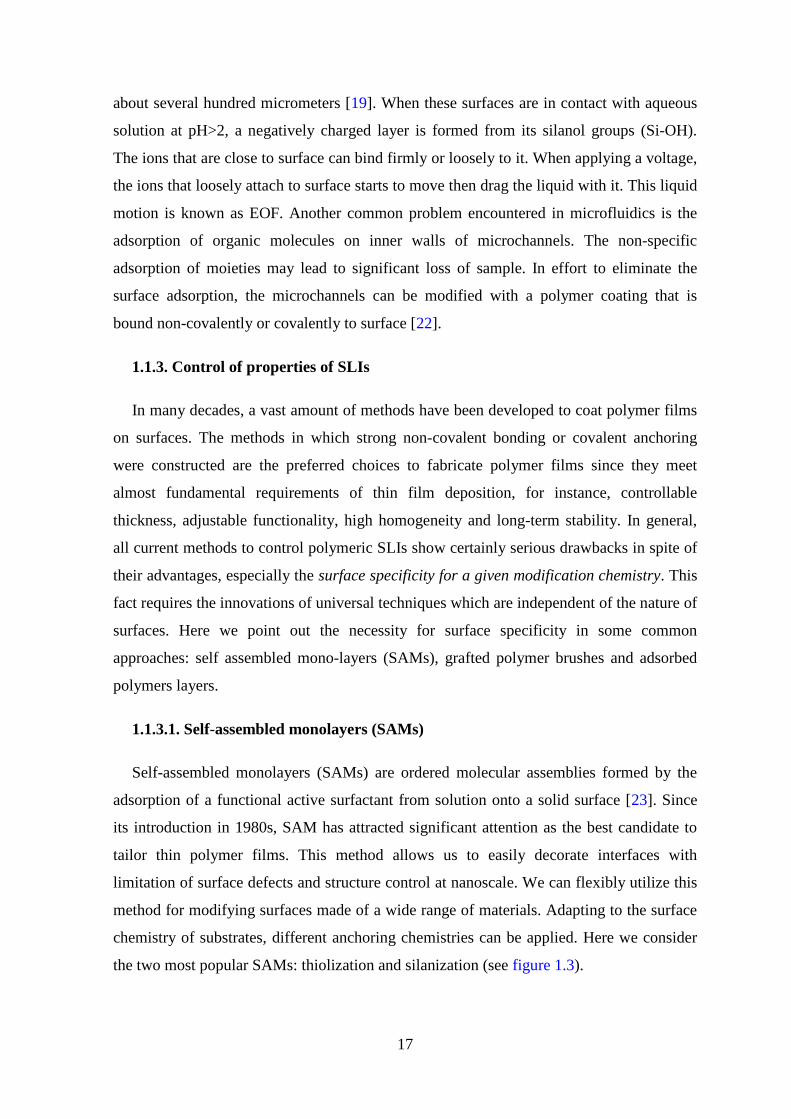
1.1.3. Control of properties of SLIs
In many decades, a vast amount of methods have been developed to coat polymer films
on surfaces. The methods in which strong non-covalent bonding or covalent anchoring
were constructed are the preferred choices to fabricate polymer films since they meet
almost fundamental requirements of thin film deposition, for instance, controllable
thickness, adjustable functionality, high homogeneity and long-term stability. In general,
all current methods to control polymeric SLIs show certainly serious drawbacks in spite of
their advantages, especially the surface specificity for a given modification chemistry. This
fact requires the innovations of universal techniques which are independent of the nature of
surfaces. Here we point out the necessity for surface specificity in some common
approaches: self assembled mono-layers (SAMs), grafted polymer brushes and adsorbed
polymers layers.
1.1.3.1. Self-assembled monolayers (SAMs)
Self-assembled monolayers (SAMs) are ordered molecular assemblies formed by the
adsorption of a functional active surfactant from solution onto a solid surface [23]. Since
its introduction in 1980s, SAM has attracted significant attention as the best candidate to
tailor thin polymer films. This method allows us to easily decorate interfaces with
limitation of surface defects and structure control at nanoscale. We can flexibly utilize this
method for modifying surfaces made of a wide range of materials. Adapting to the surface
chemistry of substrates, different anchoring chemistries can be applied. Here we consider
the two most popular SAMs: thiolization and silanization (see figure 1.3).

18
SiOO O
SiOO O
SiOO O
SiOO O
S S S SSSSS
Figure 1. 6. Illustration of Self-assembled monolayers: Silanization (left) and Thiolization (right).
Thiolization is the adsorption of organosulfure on noble metal surfaces. The thiols (e.g.,
alkyl thiol) assemblies can be spontaneously adsorbed by immersing freshly clean metal
substrate (e.g., gold) into dilute thiol solutions in an organic solvent. This is based on the
high affinity between organosulfures and metal surfaces [24]. The interest in alkanethiol
SAMs stems from their stability and ease of preparation [25]. In addition, the organic
monolayers that adsorb onto surfaces are usually well-organized even at nano-scale [26].
The metal surfaces modified by this method show potential applications in biosensors,
biomimetics, and anti-corrosion [27]. Despite of its advantages, thiols, in general, show
low physical and chemical stability due to their facile oxidation. And above all, this
method works only on metal substrates with gold being the best candidate for this
chemistry.
Silanization is the assembly of organosilicon derivatives onto silicon oxide, quartz,
glass, mica, etc. A simple immersion of the mentioned substrates into dilute solution of
silanes (e.g., OTS, APTES) can spontaneously form these organic assemblies on surfaces
[28, 29]. This results from the chemical reactions between compounds containing silane
groups and surfaces containing silicon oxides [29]. In this method, the molecules that
anchor to surfaces can self-assembly into highly ordered monolayers [30]. The surfaces
modified by this method have received considerable attention in biology and microfluidics
[31]. However, the high moisture-sensitivity of silane molecules (particularly in case of
chlorosilanes) requires us to handle carefully these chemicals during the assembly steps.

19
1.1.3.2. End-tethered polymers at SLIs
To graft polymer chains onto surfaces, the covalent bonding is the preferred choice in
most cases [32]. There are two main methodological strategies to graft a polymer brush: (i)
“grafting to” and (ii) “grafting from” (see figure 1.4).
X X X X XI I I I I
Physisorption and/ or chemisorption ofpreformed building blocks
Surface initiated polymerization
Grafting to
Grafting from
X
Figure 1.7. Adaptable approaches to grafting polymer brushes on a wide range of materials:
“Grafting to” - Physisorption and/or chemisorptions of functionalized polymers on pretreated
surfaces; “Grafting from” – Surface initiated polymerization of monomers on surfaces where
initiators was pre-immobilized.
(i) Grafting to - low density - mushroom regime
In “grating to” methods, the polymer chains that were functionalized with reactive
functional groups are grafted to a surface. The common reactive functional groups include
thiols, silanes, amino or carboxylic groups. This technique usually shows low grafting
density due to “excluded volume effect”. The repulsion between already grafted polymer
chains and the incoming new one from solution can perturb its attachment onto a surface
[33]. In this case, the polymer chains are tethered on surfaces in a low-density, mushroom
regime.
(ii) Grafting from – high density – brush regime
In “grafting from” methods, the monomers are polymerized from surfaces that were
previously modified with initiators. This strategy shows much higher grafting density
compared to that of “grafting to” strategy. With the advances in polymer synthetic

20
methodologies and their adaptation to surface chemistry, these methods allow us to graft
polymer chains on a variety of material surfaces with controllable properties. They can be
implemented with almost all available polymerization techniques: ring opening metathesis
polymerization (ROMP), nitroxide-mediated polymerization (NMP), atom transfer radical
polymerization (ATRP), single-electron transfer living radical polymerization (SET-LRP),
or reversible addition fragmentation chain transfer (RAFT) polymerization [32]. In this
case, the polymer chains are tethered on surfaces in brush regime where they are stretched
away from grafting surfaces like bristles in a brush [34].
Polymer brush has been studied in many decades. It was first noted as densely tethered
polymer chains on interfaces in 1976 by Alexander and de Gennes [33]. These scientists
have established the foundation for theoretical analysis based on scaling theory to study
polymer brushes. They have pointed out the “excluded volume effect” (a kind of steric
effect) in which the repulsion is set up between polymer chains due to spatial confinement.
At sufficiently high grafting density of polymer chains on surfaces, an entropy barrier is
established. That energy fence forces polymer chains to repulse each others, stretch away
from surfaces, as well as repel external objects that approach surfaces. Therefore, polymer
brushes exhibit anti-fouling properties and minimize the adsorption of molecules on solid
surfaces.
1.1.3.3. Adsorbed polymer layers
Polymers can adsorb from solution onto surfaces if the interaction between the polymer
and the surface is more favorable than that of the solvent with the surface and/or the
polymer [35]. This can be accomplished either (i) by the adsorption of certain neutral
polymers on specific surfaces or (ii) by the adsorption of polyelectrolytes (ionic or anionic)
on charged surfaces.
(i) Neutral Polymers:
Some neutral polymers (e.g., PS, PDMA, PHEA, PEO, etc) show the ability to adsorb
physically on solid surfaces (e.g., silica, glass) [36]. It was believed that the attractive
interactions (e.g., Van der Waals forces, dipolar forces, hydrogen bonds, and etc) between
polymer chains and the surface are the origin of polymer adsorption. The tendency of
polymer chains (adsorb to surface or not) is determined by the nature of surface, absorbing
polymer, and solvency condition [35]. If the polymer prefers the surface to the solvent,

21
polymer chains are adsorbed to. On the other hand, we have polymer depletion if the
polymer prefers the solvent to the surface. Figure 1.5 represents the differences between
adsorption and depletion of polymer chains on a surface. We can see the surface energy
drop in adsorption case that indicates the presence of adsorbed polymer chains on a
surface. In contrast, the slow increase in surface energy implies that polymer chains can’t
attach to the surface in depletion case.
Figure 1. 8. Adsorption and Depletion of polymer chains on surface: a) Illustration of absorbed
polymer chains, concentration profile and surface energy profile; b) Illustration of depleted
polymer chains, concentration profile, and surface energy profile. Source: De Gennes [35].
An important application of polymer adsorption is the introduction of polymer to silica
surface of a capillary. This is typically realized by rinsing the capillary with a solution
containing the polymer of interest. The goal of introducing neutral polymers to the
capillary is to eliminate sample-wall interactions as well as to stabilize Electro-Osmotic

22
Flow. For this purpose, hydrophilic neutral polymers (e.g., polysaccharide, PVA, PEO,
PVP, PDMA) seem to be good candidates [37].
(ii) Polyelectrolytes:
Polyelectrolytes are polymers with ionizable groups (anions or cations) [38]. In polar
solution (e.g., water), these ionizable groups can dissociate, providing charges on polymer
chains. When a charged surface is put in a contact with a polyelectrolyte, the electrostatic
interactions between those charged species of polymer chains and the surface are
established. The electrostatic interaction which is generally stronger than other interactions
(e.g., Van der Waals, dipolar forces, and hydrogen bonds) plays major role in governing
polymer adsorption in this case.
The most important parameters controlling the adsorption behavior of polyelectrolytes
at surfaces are: the charge density of the polymer chains (or degree of ionization); the net
surface charge density; and the ionic strength [35]. In the situation where polyelectrolytes
adsorbing on a surface of opposite charge, one can expect virtually any polymer chain to
be adsorbed. For the adsorption of polyelectrolytes having the same sign as the surface, the
absorbed amount of polymer chains is obviously less than that in the former case. The
adsorption of polyelectrolytes generally decreases with the increase in ionic strength. Café
et al., (1982) has studied the influence of ionic strength on the adsorption of sodium
carboxymethyl cellulose and poly(acrylic acid) on barium sulfate surface and found that
the increased ionic strength at alkaline pH allowed more polymer chains to adsorb to
surface [39].
To achieve thicker polyelectrolyte films, Decher et al., has proposed the superposition
of multiple polymer layers on a surface [40, 41]. He has performed the adsorption of
consecutively alternating monolayers of anionic polyelectrolyte
(polyalyaminehydrochloride) and cationic polyelectrolyte (sodium salt of polystyrene
sulfonate) on aminopropylsilanized quartz that was previously protonated with acidic
solution (as shown in figure 1.6).

23
- --------- - -
+
NH3+ Cl-
SO3- Na+
-
- --------- -+ + +++++ ++++ +
-
- --------- -+ + +++++ ++++ +
-+ + +++++ ++++ +
+ + ++++ ++++ ++
Figure 1. 9. Example of adsorption of polyelectrolytes on surfaces: Consecutively alternating
adsorption of polyalyaminehydrochloride (in red) and sodium salt of polystyrene sulfonate (in
cyan) on protonated aminopropylsilanized fused quartz [40].
1.1.4. A microchannel - scaling laws (importance of Surface to Volume ratio)
Microfluidics is a young discipline that studies the fluid flows circulating in artificial
microsystems [42]. Since its introduction in 1990s, a vast of microfluidic systems has been
fabricated, for example, electrophoretic separation systems, or micromixers, DNA
amplifiers, microcytometers, and chemical microreactors. These systems were employing
integrated microchannels as transportations of fluid flows. We discuss here some
physical phenomena in those microchannels, and above all we evaluate the competition
between facial phenomena and bulk phenomena in down-scaling.
1.1.4.1. Scaling laws in down-scaling: the predominance of surface forces on
volume forces
To study physical phenomena in microchannels, it is important to consider scaling
laws. A scaling law signifies the law of the variation of physical quantities with the size l of
a system or an object [42]. The general rule of thumb for scaling laws is: When reducing
the size l to a certain value, the quantities that are associated with the weaker exponent
become dominant. As a result, the volume forces (~l3) become negligible with respect to
surface forces (~l2) in micro- or nano- systems (see figure 1.7). With the predominance of
facial forces on bulk forces, some traditional phenomena, that we are used to at
macroscale, disappear while a series of new phenomena occur in these systems.

24
Figure 1.10. Scaling laws in down-scaling: the predominance of surface forces on volume forces.
1.1.4.2. Dimensionless numbers in microfluidics
The relative importance of physical phenomena in microfluidic systems is generally
evaluated by dimensionless numbers. Two most often mentioned numbers in microfluidics
are: Reynolds number (relating inertial forces to viscous forces) and Peclet number
(relating convection to diffusion). We will discuss here how these dimensionless numbers
scale with the typical length of a microfluidic system, i.e. channel size, and how they
indicate physical changes in down-scaling.
(i) Reynolds numbers: dominance of viscous stress
The Reynolds number is defined as the ratio of inertial forces and viscous forces:
ηUl
f
fR
v
ie == where fi is the inertial centrifugal force density, fv is the viscous force
density, l is the spatial scale, U is the characteristic velocity of the fluid, and η is its
kinematic viscosity [42].
When a fluid flows through a microchannel, typical fluid velocities do not exceed a
centimeter per second and widths of channels are on the order of tens or hundreds of

25
micrometers; it follows that, in general, Reynolds numbers in microfluidic systems do not
exceed 100 [42]. As a result, the viscous forces are dominant over inertial forces.
In the situation where viscous forces overwhelm inertial forces, the fluids flow slowly
in parallel layers without interruption between fluid layers. That simple fluid regime is
known as laminar flow [43]. The simplification of fluid dynamics provides us the
possibility to conduct precisely controllable processes, i.e. chemical reactions in laminar
flow reactor.
(ii) Péclet numbers: dominance of diffusion
The dispersion Peclet number (Pe) characterizes the relation between transport of solute
due to convection and diffusion. In the case of a microchannel, it is given byD
Ul
l
ZPe == ,
where Z is the moving distance of fluid (relating convection), U is the characteristic flow
velocity, l is the size of the system, and D is the diffusion coefficient of the solute [42].
In practice, microfluidic systems work at the average values of Peclet number (between
0.1 and 100) and diffusion is the major mixing mechanism of fluid [43]. As a result, the
mixing velocity is slow in microchannels. In addition, the Taylor dispersion that spreads
molecules along the direction of the flow is pronounced as ( DPD ez2∝ ) and it contributes
to fluid mixing in microchannels [44].
1.1.4.3. Adsorption phenomena
Adsorption is the phenomenon of the accumulation of a substance at surfaces. In
microsystems, the adsorption of biological samples on surfaces of microchannels is a
major concern.
It was known that biomolecules, e.g. proteins, can strongly adsorb to silica surfaces,
leading, for instance, to considerable peak broadening and asymmetry in electrophoretic
separations [45] and/or to sample loss in microfluidic devices. Such adsorption is stemmed
from electrostatic and / or dipolar interactions between proteins and silica surface. Indeed,
the silica surface becomes negatively charged in contact with electrolytes at pH greater
than 2 due to presence of silanol groups. Therefore, electrostatic interactions might occur
between silanol groups on surface and proteins that generally contain charged species [46].

26
Proteins can also physically adsorb to PDMS surfaces [47], interfering with the usability
of PDMS-based microfluidic devices. Hydrophobic and porous surfaces like PDMS are
known to be favorable for protein adsorption [48].
As mentioned above, the miniaturization of a system tends to enhance interfacial
phenomena, in general, and surface adsorption, in particular. It’s clear that the adsorption
at solid/liquid interfaces must be minimized to avoid a sample loss and the deterioration of
analytical performances of microfluidic systems.
1.1.5. Microfluidic devices (lab-on-chips)
1.1.5.1. Commercialization of microfluidic devices
Lab-on-chip (LOC), also called “micro total analysis system (µTAS)”, is a newly
emerging field that represents a breakthrough in biomedical analysis and diagnosis. From
historical point of view, lab-on-chips (LOCs) emerged from efforts to control liquid flow at
subnanoliter scale in the early 1990s. Over the last twenty-five years, hundreds of
microfluidic research groups and tens of microfluidic related companies have been
established. iSTAT blood analyzer (from Abbott Point of Care, USA) is among the first
commercially successful LOC products. This LOC device is an advanced blood analyzer
that provides real-time, lab-quality results within minutes, using only several blood drops.
Such a device is equipped with different cartridges which contain variety of chemically
sensitive biosensors on a silicon chip, allowing a comprehensive menu of specific
diagnostic tests (chemistries, hematology, blood gases, coagulation, and cardiac markers).
Another interesting microfluidic device is the glucose meter (from Bayer Healthcare,
Germany), which uses multiple strips integrated with optical detectors in a single package
for diabetic patients. The DNA and peptide analyzer from Agilent Technologies permit the
identification of an object (e.g., a virus) from characteristic sequences of genes. The future
development of LOCs will provide us with a variety of fluidic devices for diverse
biomedical applications.
1.1.5.2. Advantages of miniaturization and integration
Miniaturization and integration of microfluidic devices lead to many benefits. Firstly,
the cost of fabrication of microfluidic devices decreased significantly by reducing the
consumption of manufacturing materials. Secondly, the portability of miniaturized and

27
integrated devices is easier. Thirdly, it is obvious that the consumption of reagents and
analytes can be reduced significantly by decreasing the volume of a test. Lastly, the time of
analysis can be decreased by integrating multiple tasks on the same microfluidic platform
and performing analyses in serial and / or parallel manner.
Additionally, the predominance of surface phenomena on volume phenomena
(mentioned in section 1.1.4.1) offers entirely new applications that are inaccessible to
fluidic systems at macroscale. For instance, passive liquid actuation based on capillary
forces that is employed, for instance, in capillary test strips would not work on
macroscale. Other cases in which we take advantage of working on microscale are, electro-
osmotic flow actuation, hydrophobic valves in microfluidic devices [49], and surface
immobilized enzymes in enzymatic reactors and/or single cell studies in fluidic systems
[50].
1.1.5.3. Microfabrication of microfluidic devices
Depending on targeted application and cost of devices, different materials, i.e. silicon,
glass, quartz, metals and polymers can be employed in manufacturing. The choice of
manufacturing technique must be compatible with the chosen material. We present here
current microfabrication techniques that are widely used to fabricate microfluidic devices.
(i) The choice of materials
In the early days of LOCs, silicon and glass were major materials for manufacturing
microfluidic devices [51]. The use of those well-known materials allows us to enjoy the
benefits of well-developed and broadly utilized techniques in microelectronics, i.e.
photolithography and etching. Despite of their relatively high price, these materials are still
required for fabrication of some active elements (e.g., thermal actuators and detectors) that
can suffer from high temperature. Weak thermal expansion (coefficient of thermal
expansion α ~ 2.33×10⁻⁶ at room temperature, for silicon) inhibits the distortion of
microstructures as heating. Silicon is a good conductor that allows the fast thermal
dissipation which is really important in miniaturized systems.
The metals (e.g., Au, Ag, Cu) are necessary for construction of active elements that are
electrically conductive (e.g., electrodes, magnetic coils) in LOCs. Metal- based
microstructures are generally formed by electron lithography techniques. [52].

28
In several years, the polymers (epoxy, SU8, COC, PDMS, and etc) that are much
cheaper than silicon and glass have become the materials of choice for manufacturing low-
price LOCs [53]. Polymer – based microstructures can be formed by various fabrication
techniques: molding, casting, and etc.
To satisfy the low cost of device, Charlot et.al, (2008) has currently proposed to
fabricate LOCs by integrating active elements (Si, metals) into a system of channels made
of cheap materials, such as PDMS and/or SU8 and calling them hybrid microfluidic
devices or hybrid LOCs [54].
(ii) Photolithography
Photolithography is a process that plays a central role in microfabrication. This
technique is utilized to design defined microstructures on a substrate. It is realized by using
the light (X-ray, electron, or photon) to transfer geometric pattern from a photomask to a
photoresist on a substrate [53]. Typically, a photolithography process groups together
following steps: fabrication of a photomask; deposit of a photoresist on a substrate; and
transfer of a pattern from photomask to photoresist.
Fabrication of a photomask: A photomask is a transparent plate on which a defined
opaque pattern is deposited. In practice, photomasks are generally quartz plates covered
with defined patterns in chrome. Taking benefits from the development of electronic
lithography techniques, these techniques are often used to fabricate photomask with a
precision on the order of a fraction of a micrometer [42].
Deposit of a photoresist on a substrate: A photoresist film is prepared on a solid
substrate (silicon or glass) that is ready for a pattern transfer. The highly photosensitive
resists, i.e. SU8 and AZ-series, are among the materials of choice [42]. The deposit is made
using spin coating technique in which a layer of photoresist is deposited on a spinning
surface. A drop of photoresist solution at certain volume (3-4 ml, in practice) is first
dispensed at the center of a substrate. The substrate is then rotated at high velocities
(several thousand rpm) to allow the spreading of the photoresist over its surface. After a
sufficient rotation time (a few minutes), a layer of photoresist with a stable thickness is
formed on a substrate. The thickness of the obtained film varies with the viscosity, initial
concentration of photoresist solution, and rotation velocity of the substrate. At the end of
this step, the resist is heated slightly (i.e., 90°C, 2 minutes) to completely remove a solvent.

29
Pattern transfer from photomask to photoresist: The resist film is exposed to a light
beam crossing the photomask. The prepared photoresist film is previously aligned with the
photomask in an aligner (e.g., MA-6 mask aligner from SUSS MicroTec, Germany). The
light beam initiates reactions in the photoresist, therefore change its solubility in certain
solvents.
There are two types of resists: positive (e.g., AZ-series) and negative (e.g., SU8). In the
former case, the irradiated areas become soluble and removable by an organic solvent,
while the non-irradiated areas are polymerized and insoluble. In the later case, the
irradiated areas become insoluble while the other areas can be dissolved and removed by
an organic solvent.
30
(i)
(ii)
(iii)
(iv)
(v)
(vi)
(viii)
(ix)
(vii)
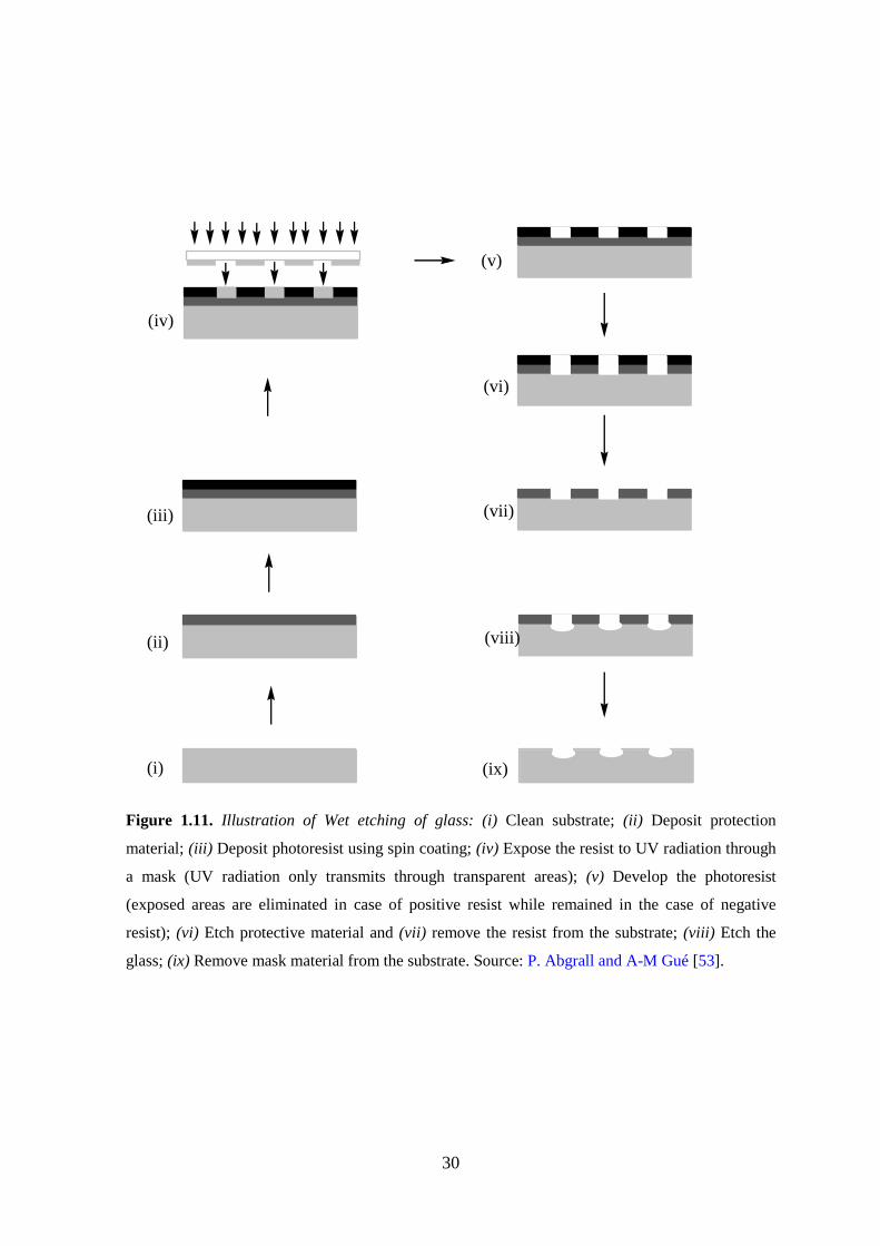
Figure 1.11. Illustration of Wet etching of glass: (i) Clean substrate; (ii) Deposit protection
material; (iii) Deposit photoresist using spin coating; (iv) Expose the resist to UV radiation through
a mask (UV radiation only transmits through transparent areas); (v) Develop the photoresist
(exposed areas are eliminated in case of positive resist while remained in the case of negative
resist); (vi) Etch protective material and (vii) remove the resist from the substrate; (viii) Etch the
glass; (ix) Remove mask material from the substrate. Source: P. Abgrall and A-M Gué [53].

31
(iii) Etching
Etching belongs to bulk micromachining technologies that form micro-patterns in the
substrate itself. In this technique, microstructures are etched on substrate by using a proper
physicochemical method. It can be achieved by either wet etching (use of chemicals, i.e.
HF or KOH) or dry etching (use of ionized gas, plasma) [53].
Figure 1.8 shows an example of wet etching of glass. First, the micro patterns on the
substrate are defined by photolithographically (i→v). The desired microstructures on the
substrate are obtained by etching of the glass substrate and removing the protective
material (vi→ix).
(iv) Molding
Molding is a replication technique that is widely used for polymer-based microfluidic
devices. The molding that employs PDMS offers an elegant solution for microfabrication.
The benefits of PDMS-based LOCs are: visualization of flows in transparent PDMS
channels; variable elasticity depending on PDMS/ reticulating agent; water tightness of
microfluidic connections due to elastomeric property of PDMS; self-adhesion to glass,
silicon or PE due to temporary hydrophilicity of oxidized PDMS surface (after oxygen
plasma treatment or immersion in a strong base); and easy peeling off from substrates due
to low surface energy.
Figure 1.9 describes molding process that is often used in clean room to manufacture
PDMS- based LOCs. We have used this process to fabricate PDMS microchannels that
were used in this work (chapter 4). The SU8 mold was first patterned by photolithography
(i), the PDMS was then molded on SU8 mold, peeled off from substrate (ii), and finally the
formed channels in the PDMS substrate are closed by a glass plate after O2 plasma
treatment (iii).

32
(i)
(ii)
(iii)
Degas PDMS solutionPour PDMS solution on SU8 moldAnnealling, 90°C, 1h
Peel off PDMS pattern
(iv)
Figure 1. 12. Illustration of Molding process of PDMS microchannels (i) SU8 mold is
photolithographically patterned; (ii) PDMS pattern is casted with using SU8 mold; (iii) PDMS
pattern is sealed by glass wafer with using plasma treatment; (iv) An example of 1D microchannel
(H×W×L = 10µm×300µm×3cm). Protocol developed by LAAS laboratory.
(i) (ii) (iii)
Figure 1. 13. Illustration of casting process: (i) Heating; (ii) Embossing; (iii) Demolding.

33
(v) Casting
Casting is another replication technique that can be applied to manufacture polymer-
based LOCs. In this technique, the polymer is pressed into a heated deformable material,
then cooled, and finally separated to obtain a defined microstructure.
Figure 1.10 illustrates the principle of casting technique. The mold (a rigid material, i.e.
silicon or a metal) is first heated to high temperature (e.g., 170°C for PMMA) at which the
polymer can deform considerably under pressure. The polymer is then pressed by heated
mold at high pressure (tens of bars) to form patterns on it (embossing). Then the polymer
bulk is removed from the mold and left cooling until a stable solid structure is obtained
(demolding). The commonly employed casting materials include PMMA, PC, PE, PET,
PVC, PEEK [42].

34
1.1.6. Conclusions
We have shown here that solid / liquid interfaces (SLIs) play a crucial role in many
different processes in biology, chemistry and physics. Along the same lines, we also put in
the evidence that SLIs become extremely important for small objects, such as particles
and/or nano- and micro-channels. This can be explained through scaling laws as the
volume forces decay much faster than the surface ones, with decreasing size of an object. It
has been well known for many years that SLIs play a crucial role in microfluidic devices
and that their role will grow even more as we move to nano-fluidics. Consequently, several
approaches to the modification of SLIs have been developed over the years and they are
based on formation of more or less organized organic layers on a solid surface. We have
described the major modification schemes of the SLIs, such as the formation of self-
assembled monolayers on silicon and/or metal surfaces, formation of end-tethered
polymers brushes and adsorption of neutral or charged polyelectrolytes on various
surfaces. All these approaches have their advantages and disadvantages but they all can be
characterized by the requirement of a surface specificity, i.e., the surface chemistry dictates
the material of choice that will be modified. The situation becomes even more difficult or
even impossible to realize when surfaces of microfluidic devices built from several
different materials have to be functionalized.
We have developed in this thesis work a surface modification scheme that is substrate
independent (works on all solid surfaces) while it offers a great variability and choice in
the physic-chemical-biological properties of the modified surfaces, spanning from passive
non-fouling, through stimuli-responsive to biologically active solid/liquid interfaces.

35
References
[1] Alberts B., Johnson A., Lewis J., Molecular biology of the cell, 4th ed., Garland Science
Press, USA (2002).
[2] S.J. Singer, G.L. Nicolson, Science, 1972, 175, pp 720-731.
[3] Bertil Hill, Ion channels of excitable membranes, 3rd ed., 2001, Sinauer Associate
Publisher, USA
[4] W.D. Stein, W.R. Leib, Transport and Diffusion across Cell Membranes, 1986,
Academic Press, USA.
[5] Thomas D. Pollard, John A. Cooper, Science, 2009, 326 (5957), pp 1208-1212.
[6] Sheryl P. Denker, Derek C. Huang, John Orlowski, Heinz Furthmayr, Diane L Barber,
Molecular Cell, 2000, 6(6), pp 1425-1436.
[7] (a) Alan Fersht, Structure and Mechanism in Protein Science: A Guide to Enzyme
Catalysis and Protein Folding, W. H. Freeman Press, USA (1998); (b) Robert A.
Copeland, Enzymes: A Practical Introduction to Structure, Mechanism, and Data
Analysis, Wiley Publisher, USA (2000).
[8] (a) Holmquist M., Current Protein and Peptide Science, 2000, 1(2), pp 209-235; (b) R.
M. C. Dawson, On the mechanism of action of phospholipase A, Biochem J.,
1963, 88(3), pp 414–423.
[9] Barry M Gubiner, Cell, 1996, 84(3), pp 345-357.
[10] Marinos C., Dalakas M.D., Neurology, 1998, 51 (6), Suppl 5 S2-S8.
[11] (a) Edward Bittar, Membranes and Cell Signaling, 1997, JAI press, England; (b) C.M.
Revankar, D.F. Cimino, L.A. Sklar, J.B. Arterburn, E.R. Prossnitz, Science, 2005, 307
(5715), pp 1625-1630; (c) Stephen S. G. Ferguson, Pharmacological Reviews, 2001,
53(1), pp 1-24.
[12] J.H. Duncan Bassett, Graham R. Williams, Trends in Endocrinology and Metabolism,
2003, 14(8), pp 356-364.
[13] (a) C.A. Ferreira, S. Aeiyach, A. Coulaud, P.C. Lacaze, J. Appl. Electrochem., 1999,
29, pp 259–263; (b) G.A. Smitha, O.I. Jude, Polymer, 2001, 42(24), pp 9665–9669; (c)
T. Tüken, G. Arslan, B.Yazici, M. Erbil, Prog. Org. Coatings, 2004, 49(2), pp 153–159.
[14] Allen J. Bard, Larry R. Faulkner, Electrochemical Methods: Fundamentals and
Applications, 2rd ed., Wiley Publisher, USA (2000).
[15] Michel Boudart, J. Mol. Catalysis, 1985, 30 (1-2), pp 27-38.

36
[16] J. M. Thomas, W. J. Thomas, Principles and Practice of Heterogeneous Catalysis,
Wiley Publisher, USA (1996).
[17] C.M. John, J.T. Arthur, Biomaterials, 2000, 21(23), pp 2335–2346.
[18] Freed L.E., Vunjak-Novakovic G., Biron R.J., Eagles D.B., Lesnoy D.C., Barlow
S.K., Langer R., Biotechnology, 1994, 12(7), pp 689-693.
[19] Patrick Tabeling, Introduction to Microfluidics, Oxford University Press, UK (2005).
[20] F. Tagliaro, G. Manetto, F. Crivellente, F.P. Smith, Forensic Sci. Int., 1998, 92 (2-3),
pp 75–88.
[21] H. Stellan, J. Chromatogr. A, 1985, 347, pp 191–198.
[22] (a) Ken K.C. Yeung, Charles A. Lucy, Anal. Chem., 1997, 69 (17), pp 3435–3441; (b)
John K. Towns , Fred E. Regnier, Anal. Chem., 1991, 63 (11), pp 1126–1132; (c) R.
Nehmé , C. Perrin, Methods Mol. Biol., 1996, 984, pp 191-206.
[23] U. Abraham, Chem. Rev., 1996, 96, pp 1533–1554.
[24] G.E. Poirier, E.D. Pylant, Science, 1996, 272, pp 1145–1148.
[25] (a) D.B. Colin, E. Joe, M.W. George, J. Am. Chem. Soc., 1989, 111(18), pp 7155–
7164; (b) G.N. Ralph, L.A. David, J. Am. Chem. Soc., 1983, 105(13), pp 4481–4483.
[26] (a) D.B. Colin, M.W. George, Science 240, 1988, pp 62–63; (b) D.P. Marc, B.B.
Thomas, L.A. David, E.D. Christopher, J. Am. Chem. Soc., 1987, 109(12), pp 3559–
3568 (1987).
[27] (a) Th. Wink, S. J. van Zuilen, A. Bult and W. P. van Bennekom, Analyst, 1997,
122, pp 43R-50R; (b) Anne L. Plant, Langmuir, 1993, 9 (11), pp 2764–2767.
[28] O. Steffen, J.R. Bart, N.R. David, Angew. Chem. Int. Ed., 2005, 44(39), pp 6282–
6304.
[29] H. Claudia, H. Stephanie, S.S. Ulrich, Chem. Soc. Rev., 2010, 39, pp 2323–2334.
[30] S. Jacob, J. Am. Chem. Soc., 1980, 102(1), pp 92–98.
[31] Mingxian Huang, Eva Dubrovcakova-Schneiderman, Milos V. Novotny, Hafeez O.
Fatunmbi, Mary J. Wirth, J. Microcolumn Separations, 1994, 6(6), pp 571–576.
[32] A. Omar, J. Polym. Sci. Part Polym. Chem., 2012, 50 (16), pp 3225–3258.
[33] (a) P.G. De Gennes, J. Physic Paris, 1976, 37, pp 1445–1452 ; (b) S. Alexander,
Physic Paris, 1977, 38(8), pp 977–981; (c) M. Daoud, P.G. De Gennes, J. Physic Paris,
1977, 38(1), pp 85–93; (d) P.G. De Gennes, Macromolecules, 1980, 13(5), pp 1069–
1075; (e) P.G. De Gennes, Macromolecules, 1981, 14(6), pp 1637–1644; (f) P.G. De
Gennes, Macromolecules, 1982, 15(2), pp 492–500; (g) P.G. De Gennes, J Phys Lett,
1983, 44, pp 241–246.

37
[34] (a) S.T. Milner, Eur. Lett., 1988, 7(8), pp 695–699; (b) S.T. Milner, T.A. Witten, M.E.
Cates, Macromolecules, 1988, 21(8), pp 2610–2619; (c) S.T. Milner, T.A. Witten, M.E.
Cates, Eur. Lett, 1988, 5(5), pp 413–418.
[35] P.G. De Gennes, Adv. Colloid. In. Sci., 1987, 27(3-4), pp 189–209.
[36] Eugène Papirer, Adsorption of polymer on silica surfaces, Marcel Dekker, USA
(2000), pp 463.
[37] Horvath J., Dolník V., Electrophoresis, 2001, 22(4), pp 644-655.
[38] Andrey V. Dobrynina, Michael Rubinstein, Prog. Polym. Sci.,2005, 30, pp 1049–
1118.
[39] M.C. Cafe, I.D. Robb, J. Colloid. Interface Sci., 1982, 86(2), pp 411-421.
[40] Gero Decher, Science, 1997, 277 (5330), pp 1232-1237.
[41] G. Decher, J. D. Hong, J. Schmitt, Thin Solid Films, , 1992, 210/211, pp 831-835.
[42] Patrick Tabeling, Introduction to Microfluidics, Oxford University press (2005).
[43] H.A. Stone, A.D. Stroock, A. Ajdari, Annu. Rev. Fluid Mech., 2004, 36, pp 381–411.
[44] Geoffrey Taylor, Dispersion of solute matter in solvent flowing slowly through a tube,
Proc. R. Soc. Lond. A, 219,186-203 (1953).
[45] M. Graf, R. Galera Garia, H. Wätzig, Electrophoresis, 2005, 26(12), pp 2409–2417.
[46] Irina Gitlin, Jeffrey D. Carbeck, George M. Whitesides, Angew. Chem. Int. Ed., 2006,
45, pp 3022 – 3060.
[47] J. Cooper McDonald, George M. Whitesides, Acc. Chem. Res., 2002, 35 (7), pp 491–
499.
[48] (a) L.J. Ho, K. Gilson, L.J. Whan, L. Hai Bang, J. Colloid. Interface Sci., 1998,
205(2), pp 323–330; (b) A. Yusuke, I. Hiroo, Biomaterials, 2007, 28(20), pp 3074–3082.
[49] (a) Shulin Zeng, Chuan-Hua Chen, James C. Mikkelsen Jr., Juan G. Santiago, Sensors
and Actuators B: Chemical, 2001, 79 (2-3), pp 107-114; (b) Yanying Feng, Zhaoying
Zhou, Xiongying Ye, Jijun Xiong, Sensors and Actuators A: Physical, 2003, 108 (1-3),
pp 138-143.
[50] (a) Shuichi Takayama, Emanuele Ostuni, Philip LeDuc, Keiji Naruse, Donald E.
Ingber, George M. Whitesides, Nature, 2001, 411, pp 1016; (b) McClain
MA, Culbertson CT, Jacobson SC, Allbritton NL, Sims CE, Ramsey JM., Anal
Chem., 2003, 75(21), pp 5646-5655; (c) Anna Tourovskaia, Thomas Barber, Bronwyn
T. Wickes, Danny Hirdes, Boris Grin, David G. Castner, Kevin E. Healy, Albert Folch,
Langmuir, 2003, 19, 4754-4764; (d) Mathieu Foquet , Jonas Korlach , Warren R.
Zipfel , Watt W. Webb , Harold G. Craighead, Anal. Chem., 2004, 76 (6), pp 1618–
38
1626; (e) Munce NR, Li J, Herman PR, Lilge L., Microfabricated system for parallel
single-cell capillary electrophoresis, Anal Chem. 2004 Sep 1;76(17):4983-9;
[51] (a) D.H Jed, Science, 1993, 261, pp 895–897; (b) C.J. Stephen, H. Roland, B.K.
Lance, J.R. Michael, High-speed Separations on a Microchip, Anal. Chem., 1994, 66,
pp 114–1118; (c) C.J. Stephen, W.M. Alvin, J.R. Michael, Anal. Chem., 1995, 67(13),
pp 2059–2063; (d) J. Zhi-Jian, F. Qun, F. Zhao-Lun, Anal. Chem., 2004, 76(18), pp
5597–5602; (e) R.F. Bryan, T.B. Michael, Anal. Chem., 2005, 77, pp 5706–5710.
[52] Holger Beckera, Laurie E. Locasciob, Talanta, 2002, 56, pp 267–287.
[53] P. Abgrall and A-M Gué, J. Micromech. Microeng., 2007, 17, R15-R49.
[54] S. Charlot, A.M. Gué, J. Tasselli, A. Marty, P. Abgrall, D. Estève, J. Micromech.
Microeng., 2008, 18(1), pp 1–8.

39
1.2. Mussel inspired surface chemistry

40
1.2.1. Introduction
The attachment of mussel to virtually any solid materials has inspired a versatile
approach to the surface modification of a wide range of inorganic and organic materials,
resulting in new surface modification chemistry: Mussel inspired surface chemistry
(MiSC) [1]. This new technology is based on using biomimetic compounds of mussel
proteins (the catecholamine families) as bonding adhesives while dopamine is the most
widely used. The principle of this surface chemistry is the deposition of oxidized products
of those biomimetic adhesives (e.g., DOPA) on solid surfaces. In this section, we will
present the basic principles of MiSC, including oxidation of dopamine and deposition
regime of DOPA (oxidized product of dopamine), as well as the state-of-the-art of MiSC.

41
1.2.2. Principles of mussel inspired surface chemistry
1.2.2.1. Mussel adhesion
Mussel is a talented mollusk that can tether to any solid surfaces in high binding
strength under wet condition in the sea, using its adhesive proteins. To deal with the shear
forces created by waves under tidal conditions, mussel needs to anchor itself to something
fixed in the ocean. To do that, this invertebrate has built a foam plaque on the fixed objects
that it found and then adheres to them permanently. The mussel plaque is actually made of
Mytilus edulis foot proteins (Mefts) that are secreted by mussel and sent to the solid
surfaces by mussel byssus. Depending on the surfaces for adhesion, the bond strength of
the mussel attachment can be between (1×10⁶) to (10×106) Nm-2 [2]. Very interestingly, the
mussel adhesion works on any solid surfaces such as rocks, ship hulls, oil platforms and
pipelines. No substrate specificity is required for the mussel attachment. One more
interesting thing is the impervious property (or underwater behavior) of mussel adhesion.
In general, water and moisture has been supposed to be contaminant to adhesion; however
mussel can firmly secure its byssus threads to surfaces even in aqueous environment, using
its water-resistant adhesive proteins. Further studies found that the mussel adhesion is
attributed from the cross-links in catecholamine. It is indicated from the biochemical
analysis that the main components in mussel plaque are catecholamine compounds
(mostly, post-translationally modified L-DOPA1) and catechol oxidase [2]. These
compounds undergo a series of redox reactions to form a complex mixture of cross-linked
matrix. Understanding the adhesion of mussel offers the innovations in the technology of
surface modification / functionalization.
1.2.2.2. Oxidation of dopamine
In alkaline solution, dopamine in particular, and catecholamines in general, can
spontaneously be oxidized into catechol products that are similar to mussel proteins.
Messersmith et al., (2007) [1] has proposed a reaction scheme to explain the oxidation of
dopamine. According to his report, the oxidation of dopamine can be divided into two
steps: (i) Formation of catechol radicals; and (ii) Formation of cross-links between catechol
radicals (known as curing or tanning).
1 L-DOPA : 3,4-dihyroxyphenyl-L-alanine

42
NH2HO
HO
NH2O
O
HO
HOHN
O
HO NHO
HOHN
1H-indole-5,6-diol (5.6-dihydroxyinodole)dopaminechrome
leukodopaminechromedopaminequinonedopamine
oxidation rearragement
ox ida ti on
rearragementintermolecularcross-linking
(208&284nm) (310-350nm) (380-420nm)
sticky (DHI)
DOPA
Scheme 1.1. Oxidation of dopamine: The intramolecular cyclization through complex redox
reactions provides many intermediated products (quinones, chromes, indoles) [1]. The final product
(DOPA) is multifunctional glue.
(i) Formation of catechol radicals: In alkaline solution, Dopamine (DOP) undergoes
intramolecular cyclization through a series of complex redox reactions (as seen in the
scheme 1.1). A variety of intermediate compounds (quinones, chromes, indoles…) are
produced during these reactions. The products with planar structure (e.g., 5,6
dihydroxyindole (DHI) and its derivatives) are supposed to act as catechol radicals that
allow their adhesion on surfaces [3]. They are able to be conjugated together in a cross-
linking net.
(ii) Formation of cross-links between catechol radicals: Next, DHI and its derivatives
are conjugated together to create the final product in a process named curing (or tanning).
The final product is named DOPA. Until now, it is still disputed if the curing process of
DOPA is covalent polymerization or hierarchical supramolecular aggregation of monomers
[4]. In the past, DOPA was believed to be a polymer whose cross-linking is caused by
addition polymerization of unsaturated hydrocarbon. That’s why this material was known
as polydopamine (the name spontaneously implies a polymeric nature) in early days of
MiSC. However, no experimental proof is available at present to support this hypothesis.
In contrary, Daniel et al., [5] has recently proved the later hypothesis that DOPA forms a
“stacked structure” in which molecules are organized through non-covalent interactions
including charge transfer, π-stacking and hydrogen bonding of monomers (scheme 1.2).
This structure results in the high stability and insolubility of DOPA coating. Lee et al., [6]

43
also suggested that there are both covalent and non-covalent bindings in DOPA. The
physically self-assembled multimers of (DOP)nDHI having the planar geometry is tightly
entrapped within covalently polymerized DOPA net (scheme 1.3).
HO
HONH3
O
O NH
HO
HO NH
+
Cl-O
O NH
O
O NH
H
Scheme 1.2. Strong non-covalent bond in DOPA from hydrogen bond [5] .
NH2HO
HO
dopamine
HO
HOHN
HO
HOHN OH
OHNH
HO
HOHN OH
OHNH
H2N OH
OH
DHI
Dimer
Dopamine-dimer
NH2HO
HO
NH2
HO
HO
H2N
HOOH
OH
OHNH
HO
HOHN
NH2HO
HO
NH2HO
HO
NH2
HO
HO
H2N
HOOH
HO
HOHN OH
OHNH
H2N OH
OH
DOPA
Scheme 1.3. Mix of non-covalent and covalent bonding in DOPA [6] .

44
1.2.2.3. Deposition regime of DOPA-type films
It has been known that catechol is the only functional element required for adhesion of
DOPA-type adhesives [7]. Here we present two assumptions about deposition regimes of
DOPA-type films that have been proposed recently in literature.
The first hypothesis about deposition of DOPA-type films is: The affinity between
DOPA and surfaces are resulted from the strong non-covalent bonding. Scheme 1.4
il lustrates the attachment of DOPA to oxides (TiO2 and SiO2) by chemical affinity, either
coordination bonding in chelating or hydrogen bonding. It was known for long time that
catechol compounds possess remarkable affinity for metal ions that leads to formation of
coordination bonding between catechol compounds and oxide surfaces (TiO2, SiO2, Fe2O3)
[8]. Recently, it was also reported that hydrogen bonding between catechol compounds
with different materials might be the reason for the attachment of DOPA to surfaces [9].
OOOO
Ti TiO
OOTi Ti
OO
OO
Ti
OO
TiOOO
OSi
OSi
OSi
O OOOH H
a) b) c)
Scheme 1.4 Attachment of DOPA to surfaces by chemical affinity: a) The chelation of Ti ions by
catechol molecules in aqueous solutions; b) Dehydration Ti-OH substrate and formation of chelate
bidentate bonding for catechol molecules on titanium dioxide substrate; c) Hydrogen bonding of
the phenolic groups to the oxygen atoms of the cleaved mica surfaces [8, 9].
Bernsmann et al., [3] proposed that the growth of DOPA film originates from the
adsorption of catechol radicals and is then followed by the formation of a 3-D cross-
linking net (Scheme 1.5). Firstly, the intermediate oxidized products (mostly DHI and its
derivatives) that exhibit planar structures can accumulate together to form oligomers.
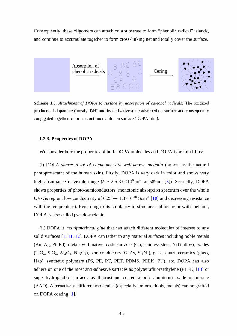
45
Consequently, these oligomers can attach on a substrate to form “phenolic radical” islands,
and continue to accumulate together to form cross-linking net and totally cover the surface.
Absorption of phenolic radicals Curing
Scheme 1.5. Attachment of DOPA to surface by adsorption of catechol radicals: The oxidized
products of dopamine (mostly, DHI and its derivatives) are adsorbed on surface and consequently
conjugated together to form a continuous film on surface (DOPA film).
1.2.3. Properties of DOPA
We consider here the properties of bulk DOPA molecules and DOPA-type thin films:
(i) DOPA shares a lot of commons with well-known melanin (known as the natural
photoprotectant of the human skin). Firstly, DOPA is very dark in color and shows very
high absorbance in visible range (ε ~ 2.6-3.0×10⁶ m-1 at 589nm [3]). Secondly, DOPA
shows properties of photo-semiconductors (monotonic absorption spectrum over the whole
UV-vis region, low conductivity of 0.25 → 1.3×10⁻¹⁰ Scm-1 [10] and decreasing resistance
with the temperature). Regarding to its similarity in structure and behavior with melanin,
DOPA is also called pseudo-melanin.
(ii) DOPA is multifunctional glue that can attach different molecules of interest to any
solid surfaces [1, 11, 12]. DOPA can tether to any material surfaces including noble metals
(Au, Ag, Pt, Pd), metals with native oxide surfaces (Cu, stainless steel, NiTi alloy), oxides
(TiO2, SiO2, Al2O3, Nb2O5), semiconductors (GaAs, Si3N4), glass, quart, ceramics (glass,
Hap), synthetic polymers (PS, PE, PC, PET, PDMS, PEEK, PU), etc. DOPA can also
adhere on one of the most anti-adhesive surfaces as polytetrafluoreethylene (PTFE) [13] or
super-hydrophobic surfaces as fluorosilane coated anodic aluminum oxide membrane
(AAO). Alternatively, different molecules (especially amines, thiols, metals) can be grafted
on DOPA coating [1].

46
(iii) With respect to morphology, DOPA film shows very rough surface with presence
of unavoidable aggregation on the scale of 102 nm [3]. Accompanying with unsmooth
topography, DOPA is believed to be amorphous material with porous structure. To our
knowledge, no quantitative investigation of the pore size distribution has been performed
yet.
(iv) The static water contact angle measurement demonstrated that the surface energy of
DOPA coatings depends on the surface of the original substrates, i.e., the contact angle
values on hydrophilic surfaces are in the range of 50-60° [1, 11] while they become much
higher on hydrophobic surfaces. For instance, the contact angles of PE and PTFE surface
decreases from 127±6° to only 92.8±1.2° and from 124±3.4° to 80.6±5.0° after
modification with DOPA, respectively [12]. Additionally, the hydrophilicity of DOPA
coated surfaces increases with an increasing thickness of the DOPA films [14].
(vi) DOPA films display a pH-dependent permselectivity. Isoelectric point (pI) of such
films was found to be close to 4 [15]. These films are permeable to cationic probe at low
pH (pH=3) and impermeable to the probe at high pH (pH=11) whereas this is reversed in
case of anionic probe.
(vii) DOPA films show strong mechanical and chemical stability [4]. For example,
DOPA films deposited on silica are stable in the presence of a physiological buffer for at
least 4 days. The stability is also excellent at pH 1: only 14% of film erosion was found
within 54 h. In contrast, the films spontaneously delaminate within 15 min of exposure to
sodium hydroxide solution at pH 13, most probably in relation to the increased solubility
of “DOPA-like materials” in basic media [3].
1.2.4. Effect of oxidation conditions on formation of DOPA-type films
The oxidation of dopamine is the key to the deposition of DOPA-type films on surfaces.
Therefore, the control of oxidation kinetics is very important in order to control the quality
of DOPA-type films.
The first protocol to achieve DOPA films was proposed by Lee [1] where very thin
adherent DOPA is formed on surfaces through a simple immersion of substrates into
alkaline solution (marine pH 8.5) of dopamine.

47
In several years, the effect of oxidation conditions (e.g., pH, temperature, dopamine
concentration, solvent and buffer use) on deposition of DOPA-type films has been studied.
The oxidation of DOPA film was found to be a pH-dependent process [16] in which the
equilibrium is shifted to the reactant when the pH decreases. An alkaline pH (pH 7.5→9.0)
is mandatory to promote deposition of DOPA films, while higher temperature leads to
thicker and rougher films [3]. Interestingly, there is no significant effect of nature of buffer
on oxidation kinetics of DOP and deposition kinetics of DOPA film [17]. The most widely
used buffer is Tris base (pKa 8.07) titrated to pH 8.5 by HCl. Some other alkaline buffers
(pKa 7.20-8.35), such as biscine and phosphate buffer have also been reported in the
literature [16, 17].
Recently, it was demonstrated that the excess of oxygen feed can lead to highly
homogeneous thin DOPA-type films (Rmsoxygen=0.52 nm compared to Rmsair=2.58 nm) via
accelerated reaction kinetics [18].
At last, oxidizing agents (e.g., cupric sulphate, ammonium persulfate) have currently
been utilized to oxidize dopamine [17, 19].
1.2.5. Applications of mussel inspired surface chemistry
The discovery of mussel inspired surface chemistry is a technological breakthrough to
overcome the difficulties in surface specific chemistry of current approaches for surface
functionalization / modification. Owning the versatile adhesion, DOPA film was used as a
“double-face tape” which can adhere to any solid surfaces by one end and allow the
attachment of certain functional molecules to the other end for decoration of surfaces. Here
are some examples:
(i) The reduction of metal ions on DOPA coating was exploited to deposit uniform
metal coatings onto substrates by electroless metallization. For example, the deposition of
silver nanoparticles on an object can be conducted through its immersion to solution of
silver nitrate of that object previously modified with DOPA film.
(ii) DOPA coatings can be also modified, through e.g., Michael addition with amines or
Schiff base reactions with thiols, with organic ad-layers [1]. A significant amount of
research has been performed to graft anti-fouling polymers (e.g., PEG, peptoids,
zwitterionics) onto surfaces via MiSC [20].
48
(iii) DOPA coating was also utilized for immobilization of biomolecules on surfaces.
For example, DOPA-PEG-biotin coatings can facilitate biofunctionalization of wide range
of materials with peptides, proteins or other biomolecules via biotin-avidin interactions
[21].
(iv) A new family of injectable citrate-based mussel inspired bioadhesives (iCMBAs)
has been synthesized by Mehdizadeh and coworkers at University of Texas (USA) in 2012
[22]. iCMBAs are PEG-based oglimers that have been functionalized with catechol-
containing compounds in one-step polycondensation. These new biomedical adhesives
outperform clinically used fibrin glue in wet tissue adhesion (they are 2.5-8.0 folds
stronger than fibrin glue). They can be used as biomimetic sealants that stop bleeding
instantly, which is quite challenging to do with fibrin glue.
(v) MiSC can provide a versatile platform technology for developing scaffold materials
for tissue engineering [23]. For instance, Tsai et al., (2011) demonstrated that the
deposition of a DOPA layer on 3D porous scaffolds is a promising strategy for cartilage
tissue engineering, and may be applied to other types of tissue engineering [24].
(vi) DOPA was used for biofunctionalization to incorporating sensitive biological
molecules (antibodies, enzymes, nucleic acids, cells) on surfaces of biosensors. For
example, DOPA film was employed as a platform to functionalize carbon nano-tubes
(CNTs) with folic acid (CNTs@PDA-FA), allowing detection of folate receptor positive
tumor cells by specific recognition [25].
(vii) In last five years, MiSC has been applied for the modification of inner wall of
capillary, allowing an enhancement of CE separation of proteins via controllable EOF and
decreased adsorption. Messersmith et al., (2012) used MiSC for the covalent
immobilization of trypsine onto silica or titania monolithic supports for protein digestion
[26].
(viii) Lee and coworkers [27] fabricated a new surface tension confined droplet 2D,
gravity-driven micro-fluidic device, called “polydopamine micro-fluidic system”. Spatially
controlled modification of the AAO surface through DOPA coating generates hydrophilic
microlines on superhydrophobic surface, allowing the gravity-driven movement of droplet
with low dragging force. This microfluidic device enables one to control movements of
droplets as well as droplet mixing.

49
(ix) MiSC was also utilized as a simple and universal platform for micro-contact
printing [28]. Tsai developed tunable micro-patterned substrates based on DOPA
deposition via micro-contact printing with PDMS stamp for biomedical applications [29].
The DOPA patterns printed on cytophobic and non-fouling substrates were used to form
patterns of cells or proteins. DOPA imprints reacted with nucleophile amines or thiols to
conjugate PEG for creating non-fouling area on surfaces.

50
1.2.6. Conclusions
MiSC opens a new strategy in surface science. This surface chemistry is based on
oxidation of catecholic compounds (e.g., dopamine) that have structural similarity with
mussel adhesive proteins. The oxidized products of these compounds can act as
multifunctional glue that can easily attach to virtually any material surfaces (e.g., metals,
semiconductors, oxides, plastics, polymers, etc). Therefore, MiSC is an elegant solution to
overcome all difficulties of specific surface chemistry in functionalizing / modifying
materials surfaces.
Additionally, in MiSC, functionalizing organic molecules (e.g., polymer chains) with
amino end-group can help to promote their attachment to grafting sites on surfaces. Chain
transfer atom polymerization (CTRP) is among the effective methods to synthesize amino
terminated water soluble polymers. In the next sections of this thesis (chapter 3, 4, 5), we
are going to develop a protocol that is based on MiSC to graft amine terminated polymers
that is synthesized by CTRP on different materials surfaces commonly used in hybrid
devices.

51
References
[1] H. Lee, S.M. Pellatore, P.B. Messersmith, Science, 2007, 318, pp 426–430.
[2] G.S Heather, F.R. Francisco, Mar. Biotechnol., 2007, 9(6), pp 661–681.
[3] F. Bernsmann, A. Ponche, C. Ringwald, J. Hemmerlé, J. Raya, B. Bechinger, J.C.
Voegel, P. Schaaf, V. Ball, J. Phys. Chem. C, 2009, 113(19), pp 8234–8242.
[4] V. Ball, D.D. Frari, M. Michel, M.J. Buehler, V. Toniazzo, M.K. Singh, Jose Gracio,
David Ruch, Bio. Nano Sci., 2012, 2(1), pp 16–34.
[5] D.R. Dreyer, D.J. Miller, B.D. Freeman, D.R. Paul, C.W. Bielawski, Langmuir, 2012,
28(18), pp 6428–6435.
[6] S. Hong, Y.S. Na, S. Choi, I.T. Song, W.Y. Kim, H. Lee, Adv. Funct. Mater., 2012,
22(22), pp 4711–4717.
[7] Y. Qian, Z. Feng, L. Weimin, Chem. Soc. Rev., 2011, 40, pp 4244–4258.
[8] (a) J. Moser, S. Punchihewa, O.P. Infelta, M. Graetzel, Langmuir, 1991, 7(12), pp
3012–3018; (b) B.A Borgias, S.R. Cooper, Y.B. Koh, K.N. Raymond, Inorg. Chem.,
1984, 23(8), pp 1009–1016; (c) T. Rajh, L.X. Chen, K. Lukas, T. Liu, M.C. Thurnauer,
D.M. Tiede, J. Phys. Chem. B, 2002, 106(41), pp 10543–10552; (d) M. Vega-Arroyo,
P.R. LeBreton, T. Rajh, P. Zapol, L.A Curtiss, Chem. Phys. Lett., 2005, 406(4-6), pp
306–311; (e) T. Rajh, J.M. Nedeljkovic, L.X. Chen, O. Poluektov, M.C. Thurnauer, J.
Phys. Chem. B, 1999, 103(18), pp 3515-3519; (f) P.C. Redfern, P. Zapol, L.A. Curtiss,
T. Rajh, M.C. Thurnauer, J. Phys. Chem. B, 2003, 107(41), pp 11419–11427; (g) J.L.
Dalsin, Lijun Lin, S. Tosatti, J. Voros, M. Textor, P.B. Messersmith, Langmuir, 2005,
21, pp 640–646; (h) X. Fan, L. Lin, P.B. Messersmith, Compos. Sci. Technol., 2006, 66,
pp 1195–1201.
[9] Shao-Chun Li, Jian-guo Wang, Peter Jacobson, X.Q. Gong, A. Selloni, Y. Diebold, J.
Am. Chem. Soc., 2009, 131(3), pp 980–984.
[10] Vincent Ball, Colloids Surfaces Physicochem. Eng. Asp., 2010, 363(1-3), pp 92–97.
[11] K. Kang, I. Choi, Y. Nam, Biomaterials, 2011, 32(27), pp 374–6380.
[12] S.H. Ku, J. Ryu, S.K. Hong, H. Lee, C.B. Park, Biomaterials, 2010, 31(9), pp 2535–
2541.
[13] J. Jiang, Liping Zhu, Lijing Zhu, Baku Zhu, Y. Xu, Langmuir, 2011, 27(23), pp
14180–14187.
[14] P.G. Ognen, P. Stepan, H. Milan, C. Dagmer, P. Vladimir, R. Frantisek,
Biomacromolecules, 2011, 12(9), pp 3232–3242.

52
[15] V. Ball, Colloids Surfaces Physicochem. Eng. Asp., 2010, 363(1-3), 92–97.
[16] V. Ball, D.D. Frari, V. Toniazzo, D. Ruch, J. Colloid Interface Sci., 2012, 386(1), pp
366–372.
[17] F. Bernsmann, V. Ball, F. Addiego, A. Ponche, M. Michel, J.J. de Almeida Gracio, V.
Toniazzo, D. Ruch, Langmuir, 2011, 27(6), 2819–2825.
[18] H.W. Kim, B.D. McCloskey, T.H. Choi, C. Lee, M.J. Kim, B.D. Freeman, H.B. Park,
Appl. Mater. Interfaces, 2013, 5(2), 233–238.
[19] Q. Wei, F. Zhang, J. Li, B. Li, C. Zhao, Polym. Chem., 2010, 1, pp 1430–1433.
[20] (a) J.K. Dalsin, P.B. Messersmith, Mater. Today, 2005, 8, pp 38-46; (b) A.R. Statz,
A.E. Barron, P.B. Messersmith, Soft Matter 4,2008, pp 131-139; (c) A.R. Statz, J.
Kuang, C. Ren, A.E Barron, I. Szleifer, P.B. Messersmith, Biointerphases, 2009, 4, pp
22-32; (c) A.R. Statz, R.J. Meagher, A.E Barron, P.B. Messersmith, J. Am. Chem. Soc.,
2005, 127, pp 7972–7973; (d) N.D. Brault, C. Gao, H. Xue, M. Piliarik, J. Homola,
Biosens. Bioelectron., 2010, 25, pp 2276–2282; (e) C. Gao, G. Li, H. Xue, W. Yang, F.
Zhang, S. Jiang, Biomaterials, 2010, 31, pp 1486–1492; (f) R. Gunawan, J. King, B.P.
Lee, P.B. Messersmith, W. Miller, Langmuir, 2007, 23, pp 10635–10643.
[21] Haeshin Lee, Junsung Rho, Phillip B. Messersmith, Adv Mater., 2009, 21(4), pp 431-
434.
[22] M. Mehdizadeh, H. Weng, D. Gyawali, L. Tang, J. Yang, Biomaterials, 2012, 33(32),
pp 7972–7983.
[23] (a) E. Ko, K. Yang, J. Shin, S.W. Cho, Biomacromolecules, 2013, 14(9), pp 3202-
3213; (b) K. Yang, J.S Lee, Y.B. Lee, H. Shin, S.H. Um, J.B. Kim, K.I. Park, H. Lee,
Biomaterials, 2012, 33(29), pp 6952-6964; (c) J. Tian, S.Y. Deng, D.L. Li, D. Shan, W.
he, X.J. Zhang, Y. Shi, Biosensors and Bioelectronics, 2013, 49, pp 466-471; (d) J. Ryu,
S.H. Ku, M. Lee, C.B. Park, Soft Matter, 2011, 7, pp 7201–7206; (e) L. M. Hamming,
X.W. Fan, P.B. Messersmith, L.C. Brinson, Compos. Sci. Technol., 2008, 68(9), pp
2042–2048; (f) J. Ryu, S.H. Ku, H. lee, C.B. Park, Adv. Funct. Mater., 2010, 20(13), pp
2132–2139; (g) K.J. jeong, L. Wang, C.F. Stefanescu, M.W. Lawlor, J. Polat, C.H.
Dohlman, R.S. Langer, D.S. Kohane, Soft Matter, 2011, 7, pp 8305–8312; (h) Y.B. Lee,
Y.M. Shin, J.H. lee, I. jun, J.K. Kang, J.C. Park, H. Shin, Biomaterials, 2012, 33(33), pp
8343–8352; (i) K. Yang, J.S. Lee, J. Kim, Y.B. Lee, H. Shin, S.H. Um, J.B. kim, K.I.
Park, H. Lee, S.W. Cho, Biomaterials, 2012, 33(29), pp 6952–6964; (k) S. M. Kang, S.
Park, D. Kim, S.Y. Park,, R.S Ruoff, H. Lee, Adv. Funct. Mater., 2011, 21(1), 108–
112.

53
[24] W.B. Tsai, W.T. Chen, H.W. Chien, W.H. Kuo, M.J. Wang, Acta Biomater 7(12),
4187-4194 (2011).
[25] T.T. Zheng, R. Zhang, L. Zou, J.J. Zhu, Analyst., 2012, 137, pp 1316–1318.
[26] J.G. Rivera, P.B. Messersmith, J. Sep. Sci., 2012, 35(12), pp 1514–1520.
[27] I. You, S. M. Kang, S. Lee, Y. O. Cho, J. B. Kim, S. B. Lee, Y. S. Nam, H. Lee,
Angew. Chem. Int. Ed., 2012, 51, pp 6126-6130.
[28] (a) J. Liu, Q. Ye, B. Yu, X. Wang, F. Zhou, Chem. Commun., 2012, 48(3), pp 398–
400; (b) Q.P. Ho, S.L. Wang, M.J. Wang, Appl. Mater. Interfaces, 2011, 3, pp 496–
4503.
[29] H.W. Chien, W.H. Kuo, M.J. Wang, S.W. Tsai, W.B. Tsai, Langmuir, 2012, 28, pp
5775-5782.
54
Chapter 2: Amine terminated
polymers

55
2.1. Introduction
It is known that organic molecules that are functionalized with amino endgroup can
easily be grafted to / on DOPA films [1]. In order to decorate DOPA films with polymer
brushes, we have synthesized two different amine terminated polymers (polyacrylamide
and poly(N-Isopropylacrylamide)) by chain transfer radical polymerization. These polymer
chains were thoroughly characterized and consequently grafted on the DOPA films.

56
2.2. Materials
Monomers, N-Isopropylacrylamide (NIPAm, C6H11NO, MW 113.16, Ref. 415324-50g),
Acrylamide (AM, 99+%, electrophoresis grade, CH2CHCONH, MW 71.08, Ref. 14,866-0)
were purchased from Sigma and used as received.
Initiators, Cysteamine hydrochloride (AET.HCl,≥98%, C2H7NS.HCl, MW 113.61, Ref.
M6500) and Potassium persulfate (KPS, +99%, ACS reagent, K2S2O8, MW 270.32, Ref.
21,622-4) were purchased from Sigma and used without any purification.
Fluorescent probe, Fluorescein 5(6) isothiocyanate (FITC, ≥90% HPLC, C21H11NO5S,
MW 389.38, Ref. 46950-250mg-F) was bought from Sigma-Aldrich and used without
purification.
1-Hydroxy-benzotriazol (HOBT, +98%, purum, C6H5N3O, MW 135.13, Ref. 54802)
was purchased from Fluka.
N,N’-DicyclohexylCarbodiimide (DCC, 1.0M solution in dichloromethane,
C6H11N=C=NC6H11, MW 206.33, d 1.247, Ref. 379115) was purchased from Sigma-
Aldrich.
Patent blue VF Soidum salt (Disulfine Blue, C27H31N2NaO6S2, Ref. 76357) was bought
from Sigma-Aldrich.
Dialysis cassette with molecular weight cut-off (MWCO) of 3500Da was bought from
Fisher Scientific.
All solutions were prepared in deionized water from a Millipore’s Laboratory Water
System (Simplicity UV, Millipore, France) with a resistivity of 18.2 MΩ•cm.

57
2.3. Experiments
2.3.1. Mechanism of chain transfer radical polymerization
The mechanism of the chain transfer radical polymerization (CTRP) is illustrated as
scheme 2.1. The CTRP is generally achieved by introducing a convenient redox system
[2], such as cysteamine (chain transfer atom, CTA) and potassium persulfate (initiator,
KPS). The polymerization consists of three steps: initiation, propagation and termination.
Firstly, the redox couple (persulfate and thiol) is dissociated in the aqueous phase to form
radical initiators. In the second step (propagation), these radical initiators (with amine
functional group at one end and thiol group at the other end) attack ethane monomer at
weak pi bond and the growth of polymer chains begins. By that way, the amino group
present in chain transfer atom is conjugated to growing polymer chains. The propagation
process is continued to increase length of polymer chains until there is no more monomer
or the termination takes place.
K2S2O8 + 2 Cl- H3N+ -CH2-CH2-SH 2 KHSO4 + 2 Cl- H3N+ -CH2-CH2-S*
S2O8 2- 2 SO4-*
Cl- H3N+ -CH2-CH2
-S*+ M Cl- H3N+ -CH2-CH2-S-M*.
Cl- H3N+ -CH2-CH2
-S-Mn*+M. Cl- H3N+ -CH2-CH2-S-Mn-1
*
Cl- H3N+ -CH2-CH2
-S-Mn*+Cl- H3N+ -CH2-CH2-SH. Cl- H3N+ -CH2
-CH2-S-Mn + Cl- H3N+ -CH2-CH2-S*
Initiation
Propagation
Termination
Scheme 2. 2. Mechanism of chain transfer radical polymerization (*=radical) [2].
It was reported that CTRP provides functional polymers with both, the functional end
and desired molecular weight [2, 3]. Molecular weight (MW) of polymer increases with
increase in a monomer concentration and decrease with the decreasing CTA concentration.
The KPS concentration doesn’t seem to have any important effect on molecular weight of
synthesized polymer.

58
2.3.2. Procedure
Two series of amine terminated polymers (PAM and PNIPAM) were synthesized as the
following procedure: The monomer was dissolved in water and the solution was bubbled
with argon stream during 1-2h. The redox initiators (AET.HCl and KPS) were added
separately and rapidly into degassed monomer solution under constant temperature
(adjusted to (26±2°C) with a water bath). The reaction was preceded for 18-24h under
constant steering and argon feed. The synthesized polymers were purified by dialysis
against distilled water (dialysis cassette with molecular weight cut-off MWCO of 3500
Daltons) and freeze dried. The experimental conditions, concentrations of monomers, the
chain transfer and initiator are given in Table 2.1, together with the abbreviations of
synthesized polymers (PAM stands for polyacrylamide and PNI for poly (N-isopropyl
acrylamide)).
Table 2. 1. List of synthesized polymers.
Telomer [M] 0
(M)
[AET]0
(M)
[KPS]0
(M)
Telomer [M] 0
(M)
[AET] 0
(M)
[KPS]0
(M)
PAM5 0,85 0,042 0,017 PNI5 0,85 0,042 0,017
PAMd 0,64 0,026 0,013 PNId 0,64 0,026 0,013
PAM10 1,28 0,026 0,013 PNI10 1,28 0,026 0,013
PAMc 2,56 0,026 0,013 PNIi 1,28 0,021 0,013
PAM13 1,24 0,025 0,025 PNIa 1,28 0,013 0,013
PNI13 1,24 0,025 0,025

59
2.4. Results and discussions
The synthesized polyacrylamide and poly(N-isopropyl acrylamide) were thoroughly
characterized before their utilization for surface modification. The results of these
characterization studies and the appropriate discussion are given below.
2.4.1. Fourier transform infrared spectroscopy (FTIR)
The infrared spectra of monomers, initiators and synthesized polymer were measured
using the FTIR Spectrometer in the wave number region from 4000 to 500 cm-1. Samples
were mixed with KBr powder and compacted by pressure into pellets. The background was
measured with an empty pellet holder (without sample).
FTIR spectra of synthesized polymers demonstrated the successful polymerization with
the presence of characteristic peaks of polyacrylamide and derivatives: 2932 cm-1 (-CH2-),
1673 cm-1 (C=O), 1415 cm-1 (C-N). The absence of the peaks concerning to vinyl group
(1641 cm-1 and 989 cm-1) indicated high purity of synthesized polymers. However, no
significant signal of terminal amine group was obtained on FTIR spectra, probably due to
the low concentration of the amine group (one group per a chain).
2.4.2. Nuclear Magnetic Resonance (NMR)
The synthesized polymers were also characterized by 1H NMR on a Bruker Avance 300
spectrometer (Bruker, Germany) at 300MHz. In general, the polymer and reactive are
dissolved in deuterium oxide with concentration of 20mg/600µl.
The conversion of polymerization, calculated from 1H NMR of unpurified polymer
solutions, was found to be very high (up to 80-95%).
1H NMR spectra of purified polymers showed the well-structured polymers with high
purification. Figure 2.1 represents 1H NMR spectra of purified PAMc and PNIPAMc. The
presence of broaden multiple peak related to methylene group (PNIPAM 2.50-0.50 ppm;
PAM 2.60-0.50 ppm) instead of vinyl group (5.65-6.20 ppm) demonstrated that polymers
have been successfully synthesized and recovered with high purity. The presence of
consecutive chemical shifts (3.60 - 2.50 ppm) concerning to aliphatic end-group [4] on 1H
NMR spectra demonstrated that synthesized polymers have been functionalized. Amine

60
terminated polymers with various molecular weights have been synthesized at different
concentrations of monomers and initiators.
Figure 2. 1. 1H NMR spectra of PAMc (top) and PNIPAMc (bottom): The synthesized polymers
have functional groups at the end of linear polymer chains.
1H NMR spectra of all synthesized polymers are illustrated in figure 2.2 (PAM) and
figure 2.3 (PNIPAM). The increase in intensity of end-dead peak as increasing AET
concentration or decreasing monomer concentration indicated the decrease in molecular
weight of synthesized polymers. The exact molecular weights of these polymers will be
further determined by SEC (see 2.4.4, chapter 2).
13C NMR spectra of PAM and PNIPAM are represented in figure 2.4 and 2.5,
respectively. It is shown that the polymers were successfully synthesized, which is
indicated by the presence of peaks related to saturated carbons –CH2-CH- (42-34 ppm) and
C=O (179 ppm) as well as the disappearance of vinyl peak (140-120 ppm).

61
Figure 2.2. 1H NMR spectra of PAM synthesized at different monomer concentrations and initiator
concentrations: PAMc (black), PAM10 (cyan), PAMd (red), PAM5 (blue).
Figure 2.3. 1H NMR spectra of PNIPAM synthesized at different monomer concentrations and
different initiator concentrations: PNIa (black), PNIi (light cyan), PNI10 (blue), PNI5 (red), PNId
(bold cyan).

62
Figure 2.4. 13C NMR spectra of PAM synthesized at different monomer concentrations and
initiator concentrations: PAMc (blue), PAM10 (cyan), PAMd (red), PAM5 (green).
Figure 2.5. 13C NMR spectra of PNIPAM synthesized at different monomer concentrations and
different initiator concentrations: PNIa (cyan), PNIi (grey), PNI10 (blue), PNI5 (black), PNId
(red).

63
2.4.3. Matrix-assisted laser desorption/ionization-Time of Flight (MALDI-TOF)
The combination of nuclear magnetic resonance and mass spectroscopy based
techniques is a powerful methodology for generating information of end-group structures
[5]. Here, we used MALDI-TOF mass spectroscopy in addition to NMR analysis
(mentioned above) to study structure of PNIPAM.
Figure 2. 6. MALDI-TOF of amine terminated PNIPAM: the repeating unit corresponds to the
multiples of NIPAM monomer (Mw 113) with addition of one amino end-group per a fragment
(Mw 71). Matrix: Sinapinic acid matrix.
MALDI-TOF mass spectroscopy with 2,5-dihydroxybenzoic acid (DHB) and sinapinic
acid (SA) as matrix in addition of suitable salts, such as NaI, NaCl, was used to determine
the average molecular weight, its distribution and the structure of the polymer fragments.
The sample at concentration of 10mg/ml in THF was mixed either with DHB in THF
(50mg/ml) and NaCl/NaI in MeOH (10mg/ml) with portion of 1/30/2 or with SA
64
(10mg/ml) in H2O 0.1%/CH3CN with portion of 1/3. The polyacrylamide chains are
insoluble in organic solvents and they were not analyzed by MALDI-TOF-MS.
It can be seen from the figure 2.6 that the repeating unit corresponds to the multiples of
NIPAM monomer (Mw 113) with addition of one amino end-group per a fragment (Mw
71). The MWn measured by MALDI-TOF is smaller than that in SEC measurements (about
3kDa for DHB matrix and 5kDa for sinapinic acid). The size-discrimination at the higher
end in MALDI-TOF experiments is originated from the difficult ionization of high
molecular weight fragments.
2.4.4. Size Exclusion Chromatography (SEC)
Size exclusion chromatography (SEC) was equipped with a refractometric detector
(Shimadzu, Japan) and a static light scattering detector (Mini DawnTM Treos, Wyatt
Technology Europe GmbH, Germany). The chromatography was conducted at a flow rate
of 0.5 ml / min, using 2 columns (Shodex OH Pack SB 804 HQ and SB 802.5 HQ) and
aqueous buffer of 0.1M NaNO3 pH 7 with 200ppm NaN3 as static and mobile phase,
respectively. The sample was diluted in the mobile phase to a final concentration of 5-6 mg
/ ml and injected into the columns.
The SEC analyses provided more precise values of the molecular weights of
synthesized polymers than MALDI-TOF. It can be seen from table 2.2, the molecular
weights of synthesized polymers span in the range of 5000-15000 Da. This size
distribution is relatively high; interestingly it is greater for PAM chains than for PNIPAM
chains. The large size distribution might be useful to generate dense polymer brushes by
grafting short and long chains next to each other and minimizing the excluded volume
interaction problem2. The increase in monomer concentration or decrease in initiator
concentration led to increase in molecular weight of polymer (table 2.2).
2 Excluded volume effect: the already grafted polymer chains on a surface impede the attachment of the polymer chains approaching that surface.

65
Table 2. 2. Molecular weights (determined from SEC) of synthesized polymers.
Initial conditions SEC
Telomer [Monomer]0 (M) [AET] 0 (M) [KPS]0 (M) MW (Da) Ip
PAM5 0,85 0,042 0,017 4577 1,297
PAMd 0,64 0,026 0,013 6435 1,185
PAM10 1,28 0,026 0,013 8620 1,344
PAMc 2,56 0,026 0,013 15080 1,433
PNId 0,64 0,026 0,013 5150 1,23
PNI5 0,85 0,042 0,017 5227 1,16
PNI10 1,28 0,026 0,013 8561 1,14
PNIi 1,28 0,021 0,013 8950 1,10
PNIa 1,28 0,013 0,013 12970 1,06
66
2.4.5. Fluorescence labeling
FITC conjugation with synthesized polymers was used to demonstrate the reactivity of
amino group in the polyacrylamide chain. Fluorescein isothiocyanate (FITC) is widely
used to attach a fluorescent label to proteins [6]. Isothiocyanate group in this compound is
known to be very sensitive to amines in proteins [7]. Here, we use this fluorophore to
qualitatively evaluate the amino group in our functionalized polymers. TLC and 1H NMR
were used to study the polymer that was modified with FITC.
Labeling of the amino group on the polyacrylamide with FITC dye was performed by
Oppermann’s method [8]: we dissolved the amino-terminated polyacrylamide (AmPAM)
in 0.01M Na2CO3 (pH 11.0) to a final concentration of 50 mg / ml and we added to this
solution a five-fold molar excess, according to the total number of amine moieties in the
reaction mixture, of FITC in anhydrous DMF (20mg / 200µl). The AmPAM was
conjugated with the FITC dye in dark room during 24 hrs under permanent stirring. The
reaction is illustrated in the scheme 2.2.
TLC of polyacrylamide modified with FITC was performed with (CHCl3/MeOH=7/3)
eluent and UV detection at 365 nm. The first spot in the Fig. 2.7.b (on the left) corresponds
to the FITC alone (Rf is equal to 0.9, in agreement with literature [9]) and the third spot (on
your right) positioned at the starting line corresponds to the purified FITC-AmPAM
conjugate. In the middle, we can see the mixture of FITC and FITC-AmPAM conjugate.
These results pretty clearly demonstrate, on the qualitative level, the presence and the
reactivity of the amino group in the polymer chains.
Additionally, 1H NMR spectrum of modified polymer was also studied to confirm the
conjugation. As seen in the Fig. 2.7.c, there are peaks corresponding to aromatic groups (b,
6.61-7.86 ppm) on 1H NMR spectrum of FITC-AmPAM conjugate. These results are in
agreement with the previous works that studied the FITC labeling of other polymers [10].
From the results obtained on TLC plate and 1H NMR spectrum, it can be concluded that
our polymer has been successfully modified with FITC probe.

67
O
O
OHOHO
NCS
NH2O
O
OHOHO
NHCSNH
NahCO3 buffer, pH 9.0, 24h, darkness
Scheme 2.2. Conjugation of amine terminated polymer with FITC.
Figure 2.7. FITC conjugated polyacrylamide: a) Structural formula; b) TLC with eluent
CHCl3/MeOH=7/3 and UV stain of 365nm; c) 1H NMR in D2O (δ: 6.61-7.86ppm).
68
2.4.6. DCC/HOBT mediated amidation
In another approach, we used amidation of functional polymer with acrylic acid to
qualitatively prove the presence of amino group in poly(N-Isopropylacrylamide) chain [11,
12] (see Scheme 2.3). First, the acrylic acid was activated by using DCC: HOBT (689mg,
5.1mM) was suspended in anhydrous DCM (10ml) and added to a solution of (i) DCC
(5.3ml, 5.3mM) and (ii) acrylic acid (341µl, 4.98mM) in DCM (15ml). The reaction was
stirred for 1.5h at room temperature. The precipitated dicyclohexylurea (DCU) was
discarded by filtration. TLC was used to monitor reaction with using eluent of Cyc/AcOEt
(5/5). The visualization of the TLC plates was accomplished in UV at 254nm. Then, 1g of
amino terminated polymer was dissolved in anhydrous DCM (5ml) and added dropwise to
the filtrated solution of the activated acrylic acid. The reaction was preceded during 15h
and final product was gained by precipitation in excess Et2O and evaporation in vacuum
during 1h.
It can be seen from 13C NMR spectrum (Fig. 2.8), a peak corresponding to the vinyl
group appeared in the spectrum of the polymer modified with acrylic acid. This indicates
that the esterification was successful.

69
H2C CH
C OH
O
N C N H2C CH
C O
O
CN
HN+
(1.0 eq)
H2C CH
C O
O
CN
HNROH+ O C
HN
HNH2C C
HC O
O
R +
H2C CH
C O
O
R + NH2 ROHH2C CH
C NH
O
+
(0,2 eq)
(1.0 eq)
(1.0 eq)
DCM, 90m
DCM, 15h
AA-P
Scheme 2.3. HOBT/DCC-mediated amidation between amine terminated PNIPAM and acrylic
acid.
Figure 2.8. 13C NMR spectra (in CDCl3) of unmodified PNIPAM and PNIPAM modified with
acrylic acid: HOBT/DCC mediated amidation of PNIa with acrylic acid was conducted at RT in
DCM for 15h.
70
2.5. Conclusion
We synthesized several AmPAM and AmPNIPAM polymer chains by employing a
redox system of cysteamine and potassium persulfate. The structure of synthesized
polymers was thoroughly characterized by FITR, NMR and MALDI-TOF. The presence
and the reactivity of the amino end-group was evaluated by conjugation of the AmPAM
chains with FITC and consequent TLC, 1H NMR analysis; by reaction of AmPNIPAM
chains with acrylic acid in the presence of DCC and consequent 13C NMR analysis. The
molecular weight of the polymers was determined by MALDI-TOF and SEC. The results
of SEC are more realistic due to the size-discrimination in MALDI/TOF analyses. The
chosen polymerization protocol allowed us to synthesize well-structured polymers with
amino end-group and controllable molecular weight that were consequently utilize for
decorating various solid surfaces with polymer brushes.

71
References
[1] H. Lee, S.M. Pellatore, P.B. Messersmith, Science, 2007, 318 (5849), pp 426–430.
[2] Alain Durand, Dominique Hourdet, Polymer, 1999, 40 (17), pp 4941–4951.
[3] (a) Georges Bokias, Alain Durand, Dominique Hourdet, Macromol. Chem. Phys.,
1998, 199(7), pp 1387–1392; (b) A. G. De Boos, Polymer, 1973, 14(11), pp 587-588;
(c) Vera Ushakova, Evgenji Panarin, Elisabetta Ranucci, Fabio Bignotti, Paolo Ferruti,
Macromol. Chem. Phys., 1995, 196(9), pp 2927-2939.
[4] Laurence Petit, Carole Karakasyan, Nadège Pantoustier, Dominique Hourdet, Polymer,
2008, 48, pp 7098-7112.
[5] A.T. Jackson, D.F. Robertson, Comprehensive Analytical chemistry, Vol. 53, Chap. 5,
pp. 17, Elsevier press (2008).
[6] (a) Schreiber A.B., Haimovich J., Methods Enzymol., 1983, 93, pp 147-155; (b)
Harlow E., Lane D., Antibodies a Laboratory Manual, pp 353-355, Cold Spring harbor
Laboratory (1988).
[7] Green F.J., Sigma-Aldrich Handbook of Stains, Dyes and Indicators, pp 377 (1990).
[8] Sebastian Seiffert, Wilhelm Oppermann, Macromol. Chem. Phys., 2007, 208, pp 1744–
1752.
[9] Amy Junnila, D. Scott Bohle, Roger Prichard,Inna Perepichkaand Carla Spina,
Bioconjugate Chem., 2007, 18, pp 1818–1823.
[10] HeuiKyoung Cho, Saifullah Lone, DaeDuk Kim, Joon Ho Choi, Sung Wook Choi, Jin
Hun Cho, Jung Hyun Kim, In Woo Cheong, Polymer, 2009, 50, pp 2357–2364.
[11] F. Albericio, R. Chinchilla, D.J. Dodsworth, C. Najera, Org. Prep. Proc. Int. 33 202
(2001); Oleg Marder, F. Albericio, Chim. Oggi, 2003, 31, pp 35-40.
[12] Senthil Govindaraji, Philippe Nakache, Vered Marks, Zvika Pomerantz, Arie Zaban,
Jean-Paul Lellouche, J. Org. Chem., 2006, 71, pp 9139-9143.

72
Chapter 3: Optimization of
oxidation of dopamine

73
3.1. Introduction
The oxidation kinetics of dopamine (DOP) is supposed to be the critical parameter to
improve efficiency of surface modification in MiSC [1]. Therefore, this chapter is focused
on the investigation of the effect of oxidation kinetics on the deposition kinetics of DOPA
(oxidized dopamine) thin films and on the analysis of the surface properties (e.g.,
topography and wettability) to find out optimal condition for building up high-quality
DOPA films for subsequent grafting.

74
3.2. Materials
Chemicals
Dopamine (DOP) in the form of hydrochloride salt and tris(hydroxymethyl)-
aminomethane (Tris base, crystalline, ≥99.9%), Ammonium persulfate (AP, ACS reagent,
≥98.0%) were purchased from Sigma-Aldrich (refs H8502, T1503 and 248614) and used
without any further purification. Acrylamide (AM, electrophoresis grade, ≥99.0%), 2-
aminoethanethiol hydrochloride (AET, ≥98.0%) and potassium peroxodisulfate (KPS,
ACS reagent, ≥99.0%) were purchased from Sigma-Aldrich (refs 148660, M6500 and
216224) and used as received. All solutions were prepared in deionized water from a
Millipore Q Plus system with a resistivity of 18.2kΩ•cm.
Flat wafers
Flat wafers of various materials (silicon oxide, coverslips, silicon, gold, copper, SU8,
PDMS) were prepared. Coverslips (22×22mm) were purchased from Sigma-Aldrich.
Standard one side polished silicon wafers, Silicon oxide wafers (d~600nm) and gold
coated wafers (d=50-150nm) were supplied by LAAS laboratory. The growth of copper
layer on silicon wafer was performed by UNIVEC 450C plasma sputtering at LAAS
laboratory. SU-8, commonly used epoxy-based negative photoresist was deposited on
clean silicon wafer by spin-coating at the thickness of 800nm. Polydimethylsiloxane
(PDMS) was mixed with curing agent at proportion of 10/1, degassed with nitrogen for 1h,
then coated on clean silicon wafer by spin-coating, and finally, annealed at 90°C in oven
for 1h. All wafers were cut into (1×3cm) areas.

75
3.3. Experiments
To prepare the dopamine (DOP) solutions, a given amount of DOP was weighed and
dissolved in 50mM Tris.HCl buffer (pH 8.5) under desired oxidation conditions just before
this solution was put in contact with substrates. This high concentration of buffer inhibited
the pH drop (δpH~0.3) caused by oxidation of DOP. All experiments were conducted in
alkaline aqueous solution to promote the oxidation of DOP. In case an oxidant was used to
induce deposition, pH was slightly adjusted to be 9.0.
All wafers were sonicated in iso-propanol (IPA) and deionized water (Milli Q system,
Millipore) for 2 minutes, rinsed with water, and finally, blow dried before use. Then, clean
surfaces were quickly immersed into oxidizing dopamine solution. All substrates were kept
upright to avoid formation of micro-particles on surfaces. Then, these surfaces were rinsed
with Millipore water and dried by Nitrogen stream before storage or use. All experiments
were performed at room temperature (20-22°C). The coating procedures could be repeated
to increase the coating thickness as fresh DOP solutions were supplied. The deposits
obtained by putting solid substrates in contact with freshly prepared DOP solutions were
named DOPA films.
The oxidation kinetics of dopamine (DOP) is supposed to be the critical parameter to
improve efficiency of surface modification in MiSC. Therefore, we studied here the effect
of oxidation conditions on oxidation kinetics of dopamine as well as the deposition
kinetics, and the surface morphology. We have investigated 3 oxidation conditions of
dopamine: air bubbling, oxygen bubbling, and oxidant induced oxidation:
Air bubbling: Substrates were immersed in a dilute aqueous solution of DOP (2mg/ml,
in Tris.HCl 50mM, pH 8.5). The deposition was conducted in open glass big-col beaker by
dipping under convection (stirring) to ensure a continuous oxygen flow for oxidized-
polymerization through the water-air interface.
Oxygen bubbling: The DOP solution was prepared by dissolving a 2mg/ml DOP in
50mM Tris.HCl buffer solution (pH 8.5) then oxygenated continuously for several hours.
Oxidant induced oxidation: Ammonium persulfate at concentration of 1mg/ml was used
as oxidant to promote the oxidation of degassed DOP (2mg/ml) solution in Tris.HCl buffer
solution (50mM, pH 9.0).

76
3.4. Characterizations
3.4.1. UV-Vis absorption
The kinetics of oxidized polymerization of DOP has been studied by UV-Vis
absorption. The UV-Vis spectra of twenty-fold dilution of reaction solutions were recorded
by Specord 205 (Anlytik Jena, Germany) in the range of 250-700nm. The absorbance of
DOP solution at 282nm increases linearly versus DOP concentration in the chosen range.
A calibration curve (absorbance at 282nm as a function of concentration) of DOP aqueous
solution was built in the range of 0.02-0.20mg/ml. All DOP solutions were prepared in
degassed Millipore water. The DOP consumption was determined from absorption spectra
(after baseline subtraction) in comparison with calibration curve of DOP.
3.4.2. Water contact angle
Water contact angles were measured by static sessile drop method using the GBX
digidrop goniometer (GBX, France) to determine the surface energy. For each static
contact angle measurement, a drop of certain volume was dispensed from the height of
1cm with low speed. After that, the needle was brought down into the drop from the top
center. The images of the drop were recorded by Windrop software and analyzed by
triangulation method in terms of contact angle. All measurements were performed in
ambient air at the room temperature.
3.4.3. Atomic force microscopy (AFM)
The surface morphology and topography were evaluated by a Nanoscope V Multimode
scanning probe microscope (Bruker, Germany) in the tapping mode. The advantages of the
tapping mode, compared to contact mode, are the elimination of a large part of permanent
shearing forces and the causing of less damage to the sample surface, even with stiffer
probes. In this AFM mode, cantilever oscillates at a frequency lower and close to
resonance frequency. Single lever silicon probe (force constant of 3Nm-1 and resonance
frequency of 70-90 kHz) was chosen as cantilever for all measurements in compatibility
with soft polymeric films.
The images were captured in the retrace direction at a scan rate of 0.2-1.0 Hz with a set
point voltage ranging between 1.4 and 2.0 (as high as possible). Scan size was 1×1, 10×10
µm2 and image resolution was 512 samples per line. Phase and amplitude image were

77
recorded in order to reflect the chemical and geometric heterogeneity of polymer layers.
AFM measurements were conducted in ambient conditions without any special
environmental setup in the AFM instrument. Typical variations at room temperature of
several degrees have negligible effects on the results. AFM images were first-order
flattened to remove horizontal artifacts. Roughness was determined by an analysis of the
AFM height image employing Nanoscope Software version 7.0. Roughness of bare flat
wafers was measured in order to compare with modified substrates.
Notably, the AFM tip may be contaminated by the sample due to the periodical contact
between the tip and the sticky DOPA films or high surface energy PAM films. To neglect
artifacts related to polymer debris mounted on AFM cantilever, contaminated tips were
immersed in piranha solution, 70% H2SO4 and 30% H2O2, at room temperature [2, 3] for
30 minutes then ozone dehydrated before scans using ultra-violet Ozone cleaning systems
(UVOCS).
The thickness of deposited layer on hard wafers (silicon oxide or silicon) was
determined by AFM measurement after removing partly the deposited layer. The polymer
layer was scratched all the way down to the substrate with a sharp metallic object which
didn’t damage the surface topography of the glass [4]. Visible scratches on the substrate
would have been easily detected due to the sub-nanometric high resolution in the vertical
direction of AFM. The depth of polymer layer was estimated by section analysis across the
scratched area.
3.4.4. Nano analyser
The aggregation of DOPA in reaction solution was confirmed by Beckman Coulter
Delsa(TM) Nano Zeta Potential and Submicron Particle Size Analyzer. The Delsa-Nano
series from Beckman Coulter is a new generation of instruments that use photon
correlation spectroscopy (PCS), which determines particle size by measuring the rate of
fluctuations in laser light intensity scattered by particles as they diffuse through a fluid, for
size analysis measurements (size range 0.6nm-7µm). All measurements were conducted at
room temperature in Millipore water (refractive index n =1.3328, viscosity η=0.8878).
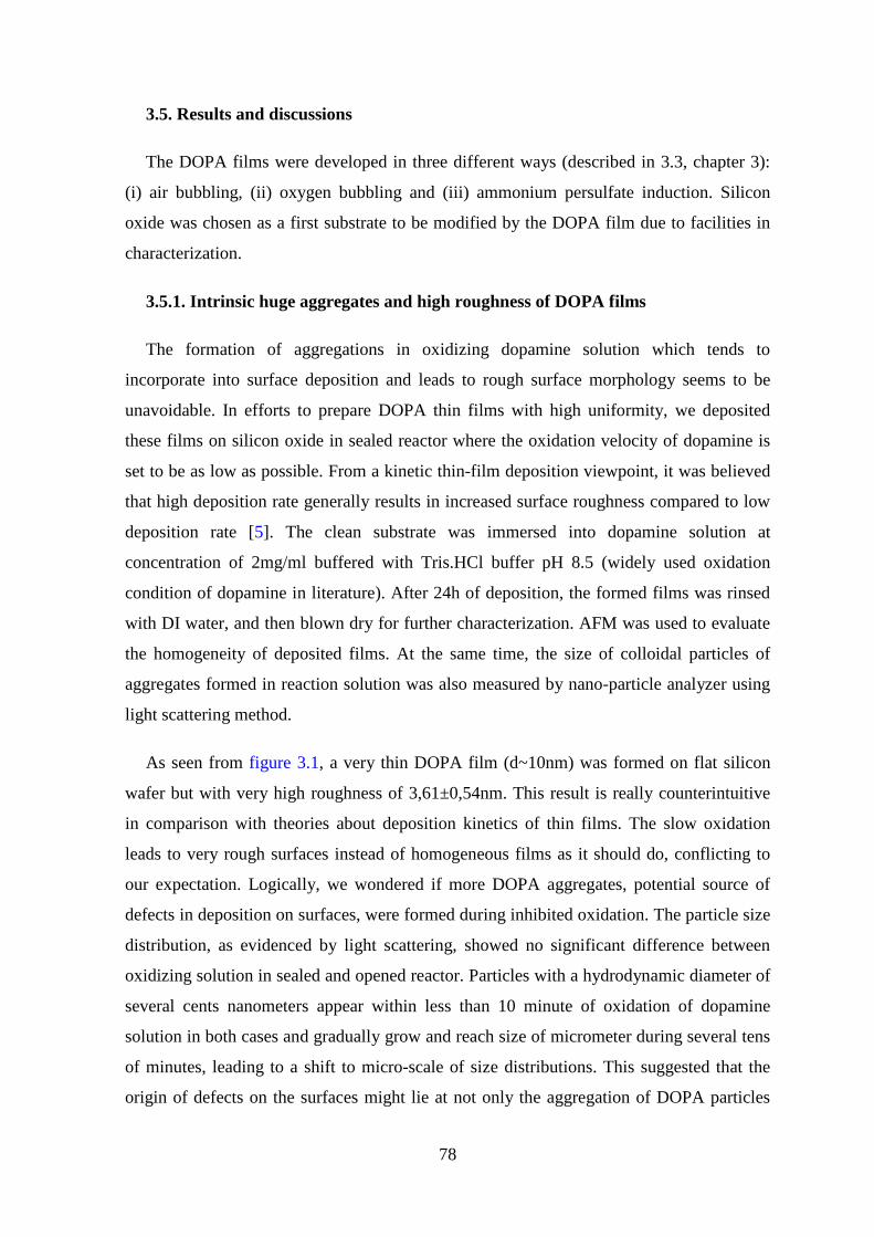
78
3.5. Results and discussions
The DOPA films were developed in three different ways (described in 3.3, chapter 3):
(i) air bubbling, (ii) oxygen bubbling and (iii) ammonium persulfate induction. Silicon
oxide was chosen as a first substrate to be modified by the DOPA film due to facilities in
characterization.
3.5.1. Intrinsic huge aggregates and high roughness of DOPA films
The formation of aggregations in oxidizing dopamine solution which tends to
incorporate into surface deposition and leads to rough surface morphology seems to be
unavoidable. In efforts to prepare DOPA thin films with high uniformity, we deposited
these films on silicon oxide in sealed reactor where the oxidation velocity of dopamine is
set to be as low as possible. From a kinetic thin-film deposition viewpoint, it was believed
that high deposition rate generally results in increased surface roughness compared to low
deposition rate [5]. The clean substrate was immersed into dopamine solution at
concentration of 2mg/ml buffered with Tris.HCl buffer pH 8.5 (widely used oxidation
condition of dopamine in literature). After 24h of deposition, the formed films was rinsed
with DI water, and then blown dry for further characterization. AFM was used to evaluate
the homogeneity of deposited films. At the same time, the size of colloidal particles of
aggregates formed in reaction solution was also measured by nano-particle analyzer using
light scattering method.
As seen from figure 3.1, a very thin DOPA film (d~10nm) was formed on flat silicon
wafer but with very high roughness of 3,61±0,54nm. This result is really counterintuitive
in comparison with theories about deposition kinetics of thin films. The slow oxidation
leads to very rough surfaces instead of homogeneous films as it should do, conflicting to
our expectation. Logically, we wondered if more DOPA aggregates, potential source of
defects in deposition on surfaces, were formed during inhibited oxidation. The particle size
distribution, as evidenced by light scattering, showed no significant difference between
oxidizing solution in sealed and opened reactor. Particles with a hydrodynamic diameter of
several cents nanometers appear within less than 10 minute of oxidation of dopamine
solution in both cases and gradually grow and reach size of micrometer during several tens
of minutes, leading to a shift to micro-scale of size distributions. This suggested that the
origin of defects on the surfaces might lie at not only the aggregation of DOPA particles
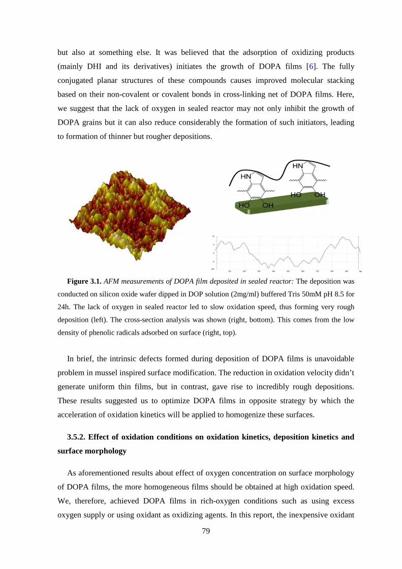
79
but also at something else. It was believed that the adsorption of oxidizing products
(mainly DHI and its derivatives) initiates the growth of DOPA films [6]. The fully
conjugated planar structures of these compounds causes improved molecular stacking
based on their non-covalent or covalent bonds in cross-linking net of DOPA films. Here,
we suggest that the lack of oxygen in sealed reactor may not only inhibit the growth of
DOPA grains but it can also reduce considerably the formation of such initiators, leading
to formation of thinner but rougher depositions.
Figure 3.1. AFM measurements of DOPA film deposited in sealed reactor: The deposition was
conducted on silicon oxide wafer dipped in DOP solution (2mg/ml) buffered Tris 50mM pH 8.5 for
24h. The lack of oxygen in sealed reactor led to slow oxidation speed, thus forming very rough
deposition (left). The cross-section analysis was shown (right, bottom). This comes from the low
density of phenolic radicals adsorbed on surface (right, top).
In brief, the intrinsic defects formed during deposition of DOPA films is unavoidable
problem in mussel inspired surface modification. The reduction in oxidation velocity didn’t
generate uniform thin films, but in contrast, gave rise to incredibly rough depositions.
These results suggested us to optimize DOPA films in opposite strategy by which the
acceleration of oxidation kinetics will be applied to homogenize these surfaces.
3.5.2. Effect of oxidation conditions on oxidation kinetics, deposition kinetics and
surface morphology
As aforementioned results about effect of oxygen concentration on surface morphology
of DOPA films, the more homogeneous films should be obtained at high oxidation speed.
We, therefore, achieved DOPA films in rich-oxygen conditions such as using excess
oxygen supply or using oxidant as oxidizing agents. In this report, the inexpensive oxidant

80
(eg. ammonium persulfate) was firstly chosen as an oxidizing agent. All experiments were
performed at a constant concentration of dopamine (2mg/ml, corresponding to 10.6mM).
3.5.2.1. Effect of oxidation condition on Oxidation kinetics
The oxidation kinetics of DOP solutions was investigated by UV-Vis absorption
measurements in changing the oxidation condition.
The oxidation of dopamine was spontaneously indicated by a very quick change in color
of solution from clear and transparent to dark as the reaction proceeds to completion,
correspond to absorbance of oxidized products of DOP. Apparently, this color change in
case of oxidant induction takes place quite fast compared to the oxidation under pure
oxygen (oxygen bubbling), and extremely fast compared to that under ambient condition
(air bubbling) due to increase in oxidation speed.
Interestingly, the detailed UV-Vis analysis shows the same spectra shape in three used
oxidation conditions. A monotonic absorption spectrum of DOPA over the whole visible
Ultraviolet region that was observed, explains the very dark color of DOPA films. A valley
at 310-320nm and a broaden peak located at ~420nm were observed which correspond to
quinones and chromes (intermediate oxidized products), respectively. These observations
indicated that dopamine oxidation in all used conditions follows the same mechanism
described in Messersmith scheme [7]. These observations suggested that the excess amount
of oxygen or the replacement of oxygen by ammonium persulfate to initiate oxidation only
accelerated oxidation but didn’t change the oxidation mechanism.
We determined the DOP consumption from UV-Vis absorption spectra, by employing
our calibration curve, in order to evaluate the oxidation kinetics. Surprisingly, the complete
dopamine consumption (~ 98%) was observed after 1h of oxidation in the presence of
ammonium persulfate (1 mg/ml), whereas the highest dopamine consumption was only
38% in the air bubbled and 60% in the oxygen bubbled solution. These findings are
contradictory with the above conclusion that suggested the same oxidation mechanism for
all three cases. We believe that the reaction mechanism is definitely affected by the
presence of the oxidizing agent. It is known that oxidation of dopamine using oxygen as
oxidizing agent is pH-dependent process (overall oxidation reaction: DOPH+ + 2O2 <->
DOPchrome + H++ 2H2O2, as suggested by Herlinger [1]). In such a case, the oxidation of
dopamine is reversible reaction where chemical equilibrium is reached as pH of solution

81
reaches a certain values, in spite of continuous oxygen or dopamine supply. This
equilibrium is shifted to the reactant when the pH decreases and hence the deposition of
DOPA does not occur in acidic conditions. The alkaline pH is the mandatory to promote
the oxidation of DOP in aqueous condition in air and in the excess of oxygen. In contrast,
the oxidation of dopamine when using ammonium persulfate as oxidizing agent is
irreversible reaction whose termination takes place only when no more dopamine is
supplied. This also explains the formation of dopamine deposition in acidic solutions,
when Lewis acids (ammonium persulfate or copper sulfate) are used as oxidizing agents [8,
9].
3.5.2.2. Effect of oxidation condition on deposition kinetics
The deposition kinetics of DOPA on silicon oxide substrates was investigated by AFM.
Silicon oxide was chosen as a model substrate in this investigation because of its very flat
surfaces (Rms = 0,142nm). Figure 3.2 illustrated the evolution of DOPA thin films built up
in three oxidation conditions (air bubbling, oxygen bubbling, oxidant induced oxidation).
Figure 3. 2. Evolution of DOPA film on silicon oxide wafer in various oxidation conditions: air
bubbling (square), oxygen bubbling (round), oxidant (triangle).

82
It was found that the deposition kinetics of DOPA when using oxygen as oxidizing
agent could be satisfactorily fitted with an exponential decay function: d(t) = dmax.(1-exp(-
t/α)) whereas, dmax is the maximal thickness and 1/α is the kinetic constant. Therefore, the
deposition velocity is determined:
αα
α0max
max
/ )())(( dtddd
e
dt
tddv
t +−===−
and αmax
0 )0(d
tvv ===
Note also that the thickness of deposition isn’t reproducible due to the difficulties to
control oxygen amount, which results in a significant error. The values of kinetic constant
and initial velocity of deposition were determined from fitted curve are (fig. 3.3): α =14.9
(h) and v0=2.9±0.2 (nm/h) (air bubbling); α =4.09 (h) and v0=10.4±0.6 (nm/h) (oxygen
bubbling).
0 2 4 6 8 10
0
10
20
30
40
50
Thi
ckne
ss (
nm)
t (h)
oxygen bubbing
d=46,4-46,4*exp(-t/4,1)
0 10 20 30 40 50
0
10
20
30
40
50T
hick
ness
(nm
)
t (h)
air bubbling
d=46,4-46,4*exp(-t/14,9)
Figure 3.3. Deposition kinetic analysis of DOPA films in various oxidation conditions: oxygen
bubbling (left), air bubbling (right). The deposition speed increased up to 4 folders at high oxygen
concentration.
When using ammonium persulfate as oxidizing agent, a thin film of thickness about
8nm was deposited on surface within 15 minutes, corresponding to deposition velocity of
32nm/h. Nevertheless, this value increased slightly with deposition time, up to 13±1nm
after 1h of deposition, then kept constant for many hours, compared to the maximum
thickness of 40-45nm for air and oxygen induced depositions [6, 8, 10]. The exact reason
why the DOPA films in case of oxidant induction didn’t keep growing is still questionable
for us at this moment. Alternatively, the thicker films could be obtained by multi-
immersions of modified substrate into freshly prepared DOP solution until the desired
thickness is reached. We did test the deposition of oxidant induced multi-layers of DOPA
on silicon oxide substrates, and found that its thickness increase linearly with the number
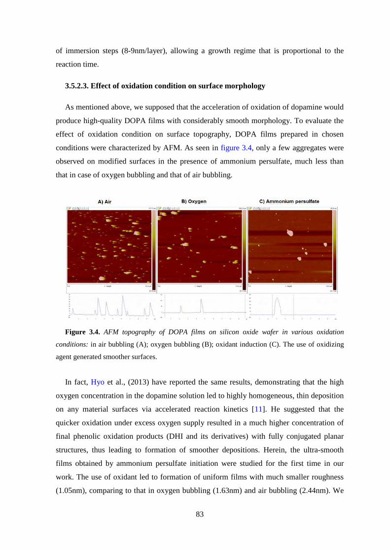
83
of immersion steps (8-9nm/layer), allowing a growth regime that is proportional to the
reaction time.
3.5.2.3. Effect of oxidation condition on surface morphology
As mentioned above, we supposed that the acceleration of oxidation of dopamine would
produce high-quality DOPA films with considerably smooth morphology. To evaluate the
effect of oxidation condition on surface topography, DOPA films prepared in chosen
conditions were characterized by AFM. As seen in figure 3.4, only a few aggregates were
observed on modified surfaces in the presence of ammonium persulfate, much less than
that in case of oxygen bubbling and that of air bubbling.
Figure 3.4. AFM topography of DOPA films on silicon oxide wafer in various oxidation
conditions: in air bubbling (A); oxygen bubbling (B); oxidant induction (C). The use of oxidizing
agent generated smoother surfaces.
In fact, Hyo et al., (2013) have reported the same results, demonstrating that the high
oxygen concentration in the dopamine solution led to highly homogeneous, thin deposition
on any material surfaces via accelerated reaction kinetics [11]. He suggested that the
quicker oxidation under excess oxygen supply resulted in a much higher concentration of
final phenolic oxidation products (DHI and its derivatives) with fully conjugated planar
structures, thus leading to formation of smoother depositions. Herein, the ultra-smooth
films obtained by ammonium persulfate initiation were studied for the first time in our
work. The use of oxidant led to formation of uniform films with much smaller roughness
(1.05nm), comparing to that in oxygen bubbling (1.63nm) and air bubbling (2.44nm). We

84
suggest that the effect of ammonium persulfate on morphology of DOPA films is two-fold,
(i) as oxidizing agent to accelerate oxidation reaction and (ii) also at its role as Lewis acid
to promote self-Michael additions between oxidizing products of dopamine, thus
increasing the curing yield of DOPA films.
3.5.3. Versatility of pseudo-melanin film
The facile introduction of a wide variety of desired properties onto virtually any
material surface is an ultimate goal in surface chemistry. The versatility of DOPA
adhesives suggested the incorporation of structurally diverse molecules onto any materials.
Here, the DOPA deposition was applied on various wetting substrates including silicon
oxide, coverslip, copper, gold, SU8, PDMS (hydrophobic surface) and silicon. These
materials were chosen as test materials since they are often used in biochemical essays and
micro-fluidic systems. The aforementioned substrates were modified with DOPA film by
immersing the substrates into an aqueous DOP solution (2mg/ml in 50mM Tris.HCl
buffer) in mentioned oxidation conditions. We measured the change in water contact angle
to confirm the film formation.
Figure 3.5. Wettability of DOPA film on various substrates: in air bubbling (red); in oxygen
bubbling (blue); in presence of ammonium persulfate (cyan). The WCA converged to a narrow
range of 50-55° though difference in initial wettability of bare surfaces.
85
As seen from figure 3.5 the water contact angles of DOPA coatings on hydrophilic
surfaces converged into narrow region (50-55°) though the initial contact angles were
ranging between 40° and 80°. The measured contact angle values are very similar to those
previously reported in the literature [7, 13].
The water contact angle on non-modified PDMS substrate was 110° while it decreased
to 92.6° after the DOPA film deposition. These results suggest that the PDMS substrate
was covered by DOPA film; however, probably there were many defects on the PDMS
surface coming from the very different stiffness of the DOPA film and the PDMS
substrate. At present, we cannot provide a better explanation as to why the water contact
angle on modified PDMS substrate did not decrease to 40-50°, however, dynamic contact
angle measurements will be performed in the future to get a better insight into the surface
chemical heterogeneity on the PDMS.
These results demonstrate the adhesion capability of DOPA films on virtually any solid
surfaces. This finding opens a route for homogenization of multi-component fluidic
devices, suggesting its potential applications in nano- and micro- fluidic systems.
86
3.6. Conclusion
In conclusion, the effect of oxidizing agent on properties of DOPA films was
investigated. The surfaces modified with DOPA were thoroughly studied by atomic force
microscopy and water contact angle measurements. The increase in deposition velocity,
accompanying with increase in oxidation speed, has shown ability to improve surface
morphology for further applications. An ultralow roughness and much less aggregates were
observed in case of oxidant induced deposition of DOPA. The deeper studies of deposition
kinetics should be conducted to find out the origin of the difference in deposition
mechanism in addition of oxidant. Here, we will choose this oxidation condition as the
optimization for the DOPA assisted surface modification (see publications in chapter 4).
Above all, the use of oxidant instead of oxygen to fabricate high-quality surface coatings
are very appealing for the modifications of channels in micro-fluidic systems, in which the
control of oxygen flow is extremely difficult.

87
References
[1] P.G. Ognen, P. Stepan, H. Milan, C. Dagmer, P. Vladimir, R. Frantisek,
Biomacromolecules, 2011, 12(9), pp 3232–3242.
[2] L. Sirghi, O. Kylian, D. Gilliland, G. Ceccone, F. Rossi, J. Phys. Chem. B, 2006,
110(51), pp 25975–25981.
[3] Y.S. Lo, N.D. Huefner, W.S. Chan, P. Dryden, B. Hagenhoff, T.P. Beebe, Langmuir,
1999, 15(19), pp 6522–6526.
[4] H.Dvir, J. Jopp, M. Gottlied, J. Colloid. Interface Sci., 2006, 304(1), pp 58–66.
[5] R.F. Xiao, N.B. Ming, Phys. Rev. E, 1994, 49(5), pp 4720–4723.
[6] F. Bernsmann, A. Ponche, C. Ringwald, J. Hemmerlé, J. Raya, B. Bechinger, J.C.
Voegel, P. Schaaf, V. Ball, J. Phys. Chem. C, 2009, 113(19), pp 8234–8242.
[7] H. Lee, S.M. Pellatore, P.B. Messersmith, Science, 2007, 318, pp 426–430.
[8] F. Bernsmann, V. Ball, F. Addiego, A. Ponche, M. Michel, J.J. de Almeida Gracio, V.
Toniazzo, D. Ruch, Langmuir, 2011, 27(6), pp 2819–2825.
[9] Q. Wei, F. Zhang, J. Li, B. Li, C. Zhao, Polym. Chem., 2010, 1, pp 1430–1433.
[10] V. Ball, D.D. Frari, V. Toniazzo, D. Ruch, J. Colloid Interface Sci., 2012, 386(1),
pp 366–372.
[11] H.W. Kim, B.D. McCloskey, T.H. Choi, C. Lee, M.J. Kim, B.D. Freeman, H.B.
Park, Appl. Mater. Interfaces, 2013, 5(2), pp 233–238.
[12] Falk Bernsmann, Melanin Made by Dopamine Oxidation: Thin Films and Interactions
with Polyelectrolyte Multilayers, thesis, Université de Strabourg, Strabourg, France
(2010).
[13] K. Kang, I. Choi, Y. Nam, Biomaterials, 2011, 32(27), pp 6374–6380.
[14] F. Yang, B. Zhao, The Open Surface Science Journal, 2011, 3, pp 115-122.

88
Chapter 4: Monitoring wettability
of heterogeneous material surfaces
in fluidic devices

89
Introduction
Here, optimized one-pot approach for mussel-inspired surface chemistry developed by
our group (see chapter 3) will be applied to control wettability of fluidic materials through
polymer coatings. The adhesive versatility of mussels for almost surfaces allowed us to
achieve a substrate-independent route for grafting end-functionalized polyacrylamide
chains onto any solid surfaces. The polymer was functionalized with amino group in chain
transfer polymerization (see chapter 2). The modified surfaces were thoroughly
characterized by water contact angle, atomic force microscopy and cyclic voltammetry.
The protein adsorption of fluorescently modified albumin on surfaces wetted by
polyacrylamide brushes was evaluated by fluorescence microscope. It was found that the
surface modified with polyacrylamide is anti-fouling. In addition to the substrate
independency of this approach, that is extremely appealing for the development of hybrid
micro- and nano-fluidic devices, this method works in a low-viscosity regime and,
therefore, is also extremely interesting for surface modification of nanometric-sized
channels.

90

91

92

93

94

95

96

97
SUPPORTING INFORMATION
Table S1. AFM analysis of DOPA and AmPAM-DOPA films on silicon oxide in
chosen oxidation conditions.
Rms air Oxygenation AP induction
Bare 0,25±0,04 0,25±0,04 0,25±0,04
DOPA 2,44±0,26 1,63±0,08 0,96±0,08
AmPAM-
DOPA 1,92±0,14 1,17±0,05 1,05±0,06
Table S2. Water contact angle of DOPA and AmPAM-DOPA films deposited on
various substrates with assistance of ammonium persulfate
Wafer Theta 0 Theta (PDOP) Theta (PAM)
SO 43±0,4 50,5±0,8 33,6±0,3
CS 46±0,3 53,9±0,4 31,5±0,8
Cu 59,4±1,5 50,2±0,5 34,6±0,9
Au 65,4±1,8 52,3±0,6 31,9±0,5
SU8 74,3±1,9 52±0,2 36,6±0,9
Si 76±0,2 50,9±0,6 36±1,0
PDMS 108,9±0,7 92,8±0,7 80,6±0,6
Table S3. AFM analysis of DOPA and AmPAM-DOPA films deposited on various
substrates with assistance of ammonium persulfate
Wafer Rmsbare (nm) RmsDOPA (nm)
RmsDOPA-AmPAM
(nm)
SO 0,25±0,04 0,96±0,08 1,05±0,06
Au 1,55±0,32 1,45±0,21 1,56±0,31
SU8 0,63±0,05 1,0±0,12 1,01±0,10
PDMS 1,23±0,17 0,58±0,04 0,59±0,07

98
Conclusions

99
In this thesis, a new and easy surface functionalization technology has been developed
for monitoring wettability of heterogeneous material surfaces in nano- and micro-fluidic
devices. This technology is based on one-pot mussel inspired surface chemistry with the
use of oxidant as oxidizing agent of dopamine, allowing us to end-graft hydrophilic
polymer brushes onto virtually any surface in a low-viscosity regime. This technology is:
(i) substrate independent (works on all solid surfaces), permitting the application of the
same experimental conditions for the modification of fused-silica capillaries and/or
channels made from glass, silicon, PDMS, SU8, COC and/or any other solid material, (ii)
accomplished in aqueous solutions and, therefore, it is compatible with grafting of
biologically active molecules, such as enzymes, (iii) easily regenerated when necessary
and, (iv) it works in a low-viscosity regime and can be employed for functionalization of
sub-micrometer sized channels.
Firstly, two series of amine terminated polymers (polyacrylamide and poly(N-
isopropylacrylamide)) have been synthesized by chain transfer radical polymerization
(CTRP). Cysteamine (HS-CH2-CH2-NH2) and potassium persulfate (K2S2O8) were used as
chain transfer atom (CTA) and initiator, respectively. The addition of amine ended chain
transfer atom (cysteamine) to growing polymer chains provides amine group at the end of
polymer chains. These functional polymers are essential for the construction of nano-
engineered polymer brushes on the studied substrates.
The structure of synthesized polymers was thoroughly characterized by Fourier
Transform Infrared spectroscopy (FTIR), Nuclear Magnetic Resonance (NMR) and
Matrix-assisted laser desorption/ionization Time-of-Flight (MALDI-TOF) mass
spectrometry. It was found that the synthesized polymers are linear and contain amino
end-group. FTIR spectra showed the characteristic peaks of polyacrylamide and its
derivatives at 2932 cm-1 (-CH2-), 1673 cm-1 (C=O) and 1415 cm-1 (C-N). The consecutive
chemical shifts (3.60-2.50 ppm) related to amino end-group were obtained on 1H NMR
spectra, suggesting the successful end-chain functionalization. 1H NMR spectra also
indicated high conversion (up to 80-95%) of polymerization and high purity of gained
polymers.
Molecular weights of polymers, determined from Size Exclusion Chromatography
(SEC), were found to be increased with increasing monomer concentration and decreasing

100
cysteamine concentration, while kept constant with varied initiator concentration. The
measured Mws were in the range of 5000 -15000 Daltons.
The amino end-group was qualitatively evaluated through its reaction with
isothiocyanate (-N=C=S) and carboxylic acids (-COOH). 1H NMR spectrum of
polyacrylamide reacted with fluorescent FITC showed chemical shifts of aromatic groups
(6.0-8.0 ppm), indicating the successful conjugation between amino end-group and cyanide
compound. Additionally, the amidation between synthesized poly(N-Isopropylacrylamide)
and acrylic acid in presence of HOBT/DCC coupling indicated the incorporation of amino
end-group on polymer chains.
Secondly, the oxidation conditions of dopamine were optimized to achieve low-
roughness DOPA films. The deposition of DOPA-type thin films on silicon oxide wafer
was investigated under three different oxidation conditions (air bubbling, oxygen bubbling
and oxidant induction).
The wetting of modified surfaces was studied by water contact angle measurements to
confirm the presence of DOPA films. It was found that surfaces modified under chosen
conditions have moderate hydrophilicity with theta values in the range of (50°-55°).
The topography of DOPA films was studied by atomic force microscopy in tapping
mode. It was seen from AFM images, the surfaces modified on all examined conditions
were covered by continuous thin films. The huge grains deposited on surfaces,
accompanying with dark aggregations in dopamine solutions was found to be
characteristics of DOPA. The slow oxidation of dopamine in sealed reactors led to very
rough films, contrary to theories as well as previously experimental reports about
deposition kinetics of thin films. The lack of oxygen might have reduced adsorption of
phenolic radicals (which initiates the deposition of DOPA-type thin films) on surfaces,
thus increased their roughness. Herein, the use of oxidant as oxidizing agent was found to
be optimal condition for surface modification by mussel inspired surface chemistry. The
presence of oxidant not only accelerated oxidation of dopamine, but also improved
dramatically properties of surfaces modified with DOPA. Very smooth surfaces (roughness
about 1 nanometer) with much less aggregations (several grains on the area of 10
micrometers square) were observed.

101
Additionally, the deposition kinetics of DOPA films was evaluated by atomic force
microscopy in tapping mode using a scratching method. Evidently, the initial deposition
velocity increased as the oxidation reaction was accelerated with excess of oxygen or
oxidant. The values determined from deposition curves are 2.9±0.2 nm/h (air bubbling),
10.4±0.6 nm/h (oxygen bubbling) and 32 nm/h (oxidant induction). A thin film of 8nm was
formed within 15 minutes of deposition on surface in case of oxidant induction. However,
this value later increased slowly with deposition time, reached to thickness of 13nm after 1
hour, and finally kept constant for many hours. Thicker films were obtained by multi-
immersions of substrate into freshly prepared dopamine solution. The thickness increase
linearly with number of immersion steps (8-9nm/layer), allowing a growth regime that is
proportional to the reaction time.
Finally, one-pot mussel inspired surface chemistry with assistance of oxidant has been
utilized for control of wetting of heterogeneous materials in nano- / micro- fluidic devices.
The simple immersion of clean substrates into one-pot mix (including dopamine, AmPAM
and oxidant) resulted in a thin coating of polymer brush on studied surfaces (DOPA-
AmPAM). The modified surfaces were characterized by analytic surface techniques,
including water contact angle, atomic force microscopy, cyclic voltammetry and protein
adsorption.
Water contact angle measurement showed that the polyacrylamide coating adhere to all
employed surfaces. And that all the materials become alike (theta of 31.5-36.6°) after the
surface coating, except PDMS that is much more hydrophobic than other material, theta of
80.6° after and 124° before modification.
Redox peaks disappeared from cyclic voltammetry curve of gold electrode modified
with DOPA-type thin films. This indicates that the surface coating hindered the
eletroactive species to get onto gold surface and almost no electron exchange was
established between the electrode and solution. We also calculated the specific capacitance
of the DOPA and DOPA-AmPAM coatings by integrating the area under CV curves. The
specific capacitance of DOPA film was 82 µF / cm2 and slightly increased (109 µF / cm2)
for DOPA-AmPAM film that could reflect high porosity of these coatings. This is an
important finding as it shows that these organic films on metals could potentially find an
application as supercapacitors or actuators.

102
The analysis of images obtained from fluorescence microscopy showed the anti-fouling
property of surface modified with DOPA-AmPAM. This comes from the entropic barrier
effect of polymer brushes.
In summary, a universal technology has been developed to functionalize various
surfaces. This new technology is based on mussel inspired surface chemistry. The use of
oxidant in one-pot approach enables us to apply this method for the modification of
heterogeneous surfaces in nano- and micro-fluidic systems. Herein, we utilized this
approach to exploit the anti-fouling properties of surfaces prepared from hydrophilic
polymer brushes, allowing minimization of protein/cell/bacteria adhesion.

103
Future outlook

104
The ultralow-fouling behavior of DOPA-AmPAM thin film towards bovine serum
albumin is important evidence that proved its ability in achieving surface coatings without
non-specific protein adsorption for nano- / micro-fluidics. However, the anti-fouling
properties of these films towards different proteins (e.g., bovine gamma globulin, serum
amyloid P component) and other biomolecules (e.g., antibodies, cells) need to be studied in
future works. Besides, hydrophilic modification of surfaces can be achieved by one-pot
mussel inspired surface chemistry using different water soluble polymers (e.g., PEG, HEC,
PVA, Poly(tertiary amide)s, PDMA, PHEA, PMMA, pSBMA, etc). The new polymer
surfaces will be exploited as novel coatings for separation of biomolecules by capillary
electrophoresis.
We have currently started to develop stimuli-responsive surfaces based on DOPA-
AmPNIPAM films using one-pot MiSC. The functional polymer has been synthesized at
our laboratory using CTRP and thoroughly characterized (see chapter 3, synthesis of amine
terminated polymer). The cell adhesion is one of the first observations that indicated the
presence of PNIPAM on modified surfaces. These stimuli-responsive polymer brushes
have many potential applications for tissue engineering and biosensors.
We expect that in the near future, this surface chemistry can be transferred onto other
materials, such as different plastics, Teflon, paper…. It is clear that we have the possibility
to apply one-pot MiSC that has been demonstrated here to be universal for any virtually
materials.

105
Résumé

106
1. Introduction
L’objectif de cette thèse était de développer une nouvelle technologie de
fonctionnalisation des surfaces dans les dispositifs nano- / micro- fluidiques. Ceci est
réalisé par l’utilisation de la chimie de surface inspirée des moules pour fonctionnaliser
des surfaces. Cette nouvelle technologie nous a permis d’homogénéiser l’énergie de
surface des matériaux étudiés.
Laboratoire sur puce (lab-on-a-chip en anglais, LOC), également appelé « Micro-
système d’analyse total (µTAS), est une nouvelle discipline qui représente une percée dans
l’analyse ainsi que le diagnostic biomédical. Cette discipline consiste à la miniaturisation
et l’intégration des dispositifs fluidiques pour l’autonomie. Du point de vue historique,
LOC a émergé des efforts pour contrôler l’écoulement liquide à l’échelle sub-nanolitre au
début des années 90. Au cours des vingt-cinq dernières années, de nombreux groupes de
recherche et des dizaines d’entreprises relatives à la microfluidique ont été établies. A
l’heure actuelle, nous pouvons facilement trouver quelques produits commerciaux basés
sur LOC, tels que l’analyseur de sang iSTAT (Abbott, USA), le glucomètre (Bayer,
Allemand) et l’analyseur de peptide et d’ADN (Agilent, USA).
Il y a plusieurs matériaux (par exemple, silicium, verre et plastiques) qui peuvent être
utilisés pour fabriquer les dispositifs microfluidiques complexes. Le matériel de choix est
régi par l’application ciblée tandis que le prix du dispositif peut jouer un rôle essentiel. On
a démontré que le coût d’un dispositif microfluidique peut être réduit considérablement en
appliquant la technologie hybride dans laquelle des actionneurs basés sur silicium sont
incorporés aux matériaux polymères non coûteux [1]. D’autre part, nous savons que la
diminution de la taille de n’importe quel dispositif entraîne une augmentation du rapport
surface / volume [2]. Ceci impose la nécessité de la modification (chimique et / ou
physique) des surfaces, particulièrement dans les dispositifs microfluidiques et
nanofluidiques consacrés aux applications biologiques. Les modifications de surface sont
généralement développées au cas par cas. Elles dépendent des propriétés des matériaux
modifiés et des molécules attachées. Les méthodes les plus généralement utilisées pour la
modification des surfaces solides incluent la formation des mono-couches auto-assemblées
(self assembled monolayers en anglais, SAMs) sur des métaux, la chimie basée sur le
silane pour les substrats de silicium et en verre, et l’assemblage couche-par-couche de
polyélectrolytes sur des surfaces chargées. Cet état de l’art de la modification de surfaces

107
nous montre l’impossibilité d’homogénéiser les propriétés des surfaces dans les dispositifs
fluidiques hybrides (l’intégration de l’ensemble de silicium, verres, métaux, résines
photosensibles, i.e. SU8, élastomères, i.e. PDMS).
La moule est un mollusque talent qui peut s’attacher sur toutes les surfaces solides à
haute force d’attachement dans les conditions humides de l’océan [3]. Pour résister aux
forces de cisaillement créées par des vagues à haute marée, la moule doit s’ancrer à
quelque chose fixé dans l’océan. A cet effet, cet invertébré construit une plaque de mousse
sur ces objets fixés, puis il adhère en permanence. L’adhérence de la moule est
exceptionnelle car elle est forte, durable, résistante à l’eau, et surtout, elle est universelle.
L’adhérence de la moule sur n’importe quelle surface solide est devenue l’inspiration
pour une technologie universelle de fonctionnalisation des surfaces : La chimie de surface
inspirée des moules (mussel inspired surface chemistry en anglais, MiSC). Cette nouvelle
technologie est basée sur l'utilisation des adhésifs (les familles de catécholamines) qui
imitent les protéines de moules dont la dopamine est la plus utilisée. Dans une solution
alcaline (pH marin), la dopamine est oxydée et forme des réactifs (nommé DOPA) qui
peuvent facilement adhérer aux surfaces solides [4]. De plus, les molécules qui sont
fonctionnalisées avec le groupement amine, thiol ou carboxyle peuvent également être
collées sur des couches de DOPA. La découverte de la chimie de surface inspirée des
moules est une percée technologique visant à surmonter les difficultés des chimies
spécifiques de surface. En général, la couche de DOPA agit comme un scotch double-face :
une face est adhérée à une surface solide et l’autre permet d’ancrer certaines molécules
désirées.
Dans cette étude, nous présentons un protocole basé sur la chimie de surface inspirée
des moules afin de greffer des chaines de polyacrylamide sur différentes surfaces solides.
Dans une solution alcaline, la dopamine s’oxyde spontanément, formant des produits
réactifs (DOPA), par conséquent, ces produits oxydés s’assemblent sur n’importe quelle
surface solide. Ceci forme une couche mince de DOPA qui peut probablement être
modifiée avec les molécules désirées. Selon la littérature, les amines, les thiols et les
groupes carboxyles réagissent avec le DOPA. Nous avons synthétisé une variété de
polyacrylamide et ses dérivés avec une fonction amine, à différents poids moléculaires. Les
polymères ont été fixés sur différents matériaux par la chimie de surface inspirée des

108
moules par une voie « one-pot » et les surfaces modifiées ont été étudiées par différents
techniques de caractérisation.
2. Expériences
2.1. Synthèse de polymères à terminaison amine
La polymérisation radicalaire de transfert de chaine est utilisée pour synthétiser les
polymères à terminaison amine. Cela est une méthode efficace qui nous permet de
synthétiser des polymères avec une terminaison fonctionnelle et un poids moléculaire
désiré [5]. Dans notre étude, la cystéamine (HS-CH2-CH2-NH2) et le persulfate de
potassium (K2S2O8) sont utilisés comme étant l’atome de transfert et l’initiateur,
respectivement.
Deux séries de polymères, i.e. polyacrylamide (abrégé AmPAM, amine terminated
polyacrylamide) et poly-N-Isopropylacrylamide (abrégé AmPNIPAM, amine terminated
poly(N-isopropylacrylamide)) ont été synthétisées par la procédure suivante: Le monomère
a été dissous dans l’eau et la solution a été bullée avec un courant d’argon pendant 1-2
heures. Les initiateurs (la cystéamine et le persulfate de potassium) ont été ajoutés
séparément et rapidement dans la solution dégazée du monomère. La température a été
gardé constante (ajustée à 26±2°C avec un bain d’eau). La réaction a été procédée pendant
18-24 heures. Les polymères synthétisés ont été purifiés par dialyse dans l’eau distillée,
utilisant une cassette de dialyse avec une valeur de coupure de poids moléculaire
(molecular weight cut-off en anglais, MWCO) de 3500 Daltons. Finalement, les polymères
synthétisés sont séchés par lyophilisation.
Les polymères synthétisés ont été caractérisés par différentes techniques : spectroscopie
infrarouge à transformée de Fourier (FTIR), résonance magnétique nucléaire (RMN),
spectroscopie de masse à désorption-ionisation laser assistée par matrice (MALDI-TOF),
et chromatographie d’exclusion stérique (SEC).
2.2. Optimisation d’oxydation de la dopamine
Dans une solution alcaline, la dopamine s’oxyde spontanément, formant des produits
réactifs (DOPA), par conséquent, ces produits oxydés s’assemblent sur n’importe quelle

109
surface solide. Ceci forme une couche mince de DOPA (schéma 1) qui peut probablement
être modifiée avec les molécules désirées.
NH2HO
HO
NH2O
O
HO
HOHN
O
HO NHO
HOHN
1H-indole-5,6-diol (5.6-dihydroxyinodole)dopaminechrome
leukodopaminechromedopaminequinonedopamine
oxidation rearragement
ox ida ti on
rearragementintermolecularcross-linking
(208&284nm) (310-350nm) (380-420nm)
sticky (DHI)
DOPA
Schéma 1. Oxydation de la dopamine : L’oxydation de la dopamine mène à la formation de
plusieurs produits intermédiaire (quinones, chromes, indoles) et le produit final est nommé DOPA.
La structure de DOPA n’est pas encore défini mais il est bien connu que le DOPA est une colle
multifonctionnel.
La cinétique d’oxydation de la dopamine est le paramètre critique pour améliorer
l’efficacité de la modification de surfaces avec la chimie de surface inspirée des moules.
L’effet de la cinétique d’oxydation sur la cinétique de dépôt des couches minces de DOPA
(dopamine oxydée) est étudié sous trois conditions d’oxydation: (i) bullage d’air ; (ii)
bullage d’oxygène en excès; (iii) utilisation d’un oxydant. L’oxyde de silicium est employé
comme le premier substrat en raison de sa caractérisation facile.
(i) Bullage d’air: Des substrats ont été plongés dans une solution diluée de dopamine,
dans le tampon Tris.HCl 50 mM, titré à pH 8.5 (pH marin), à concentration de 2 mg / ml.
Le dépôt a été effectué dans un bécher ouvert à grand col sous une agitation permanente
pour assurer un écoulement continu de l’oxygène.
(ii) Bullage d’oxygène en excès : Des substrats ont été plongés dans une solution diluée
de dopamine, dans le tampon Tris.HCl 50 mM, titré à pH 8.5, à concentration de 2 mg / ml.
Le dépôt a été effectué sous oxygène en excès. Le courant d’oxygène est toujours mis le
plus fort possible.

110
(iii) Utilisation d’un oxydant: des substrats ont été plongés dans une solution diluée de
dopamine, dans le tampon Tris.HCl 50 mM, titré à pH 9.0, à concentration de 2 mg / ml.
Le persulfate d’ammonium à la concentration de 1 mg/ml a été ajouté dans la solution de
dopamine afin d’oxyder celle-ci.
Tous les substrats ont été nettoyés par sonication dans l’isopropanol et l’eau déionisée
pendant deux minutes, puis rincés avec l’eau, et finalement séchés avant la modification.
Les surfaces propres ont été rapidement plongées dans la solution de dopamine durant son
oxydation (bullage d’air, bullage d’oxygène ou utilisation d’un oxydant). Les substrats
étaient maintenus verticaux pour éviter la formation de microparticules sur les surfaces.
Puis, celles-ci ont été rincées avec l’eau Millipore et séchées avec un courant d’azote avant
stockage ou utilisation. Toutes les expériences ont été exécutées à température ambiante
(20-22°C). Les procédures de dépôt pourraient être répétées pour augmenter l’épaisseur de
la couche de DOPA.
Les propriétés des surfaces (par exemple, topographie et mouillabilité) seront étudiées
pour mettre au point des conditions d’oxydation de la dopamine, afin d’obtenir des couches
de DOPA de haute qualité (moins d’agrégation avec une rugosité réduite). La condition
optimale sera plus tard appliquée dans la modification des surfaces avec les chaines de
polymère utilisant la chimie de surface inspirée des moules par une voie « one-pot ».
2.3. Modification de surface avec polyacrylamide par la chimie de surface inspirée
des moules par une voie « one-pot »
Nous avons développé un protocole universel pour greffer des chaines de polymère
hydrophile sur des surfaces solides. Ceci est accompli par la chimie de surface inspirée des
moules par une voie « one-pot ». Les surfaces étudiées sont modifiées après immersion
dans une solution alcaline one-pot, contenant le tampon Tris.HCl 50 mM à pH 9.0, la
dopamine à la concentration de 2 mg / ml, le polyacrylamide à terminaison amine
(AmPAM) à la concentration de 1 mg/ml, et le persulfate de ammonium (oxydant) à la
concentration de 1 mg/ml. Généralement, une solution nouvellement préparée est injectée
dans un canal microfluidique et / ou des substrats plats sont plongés dans cette solution
pendant quelques heures (habituellement trois heures), et par conséquent, les canaux et / ou
les substrats sont rincés et ultérieurement séchés avec un courant d’azote avant utilisation
ou caractérisation. Toutes les expériences ont été exécutées à température ambiante (20-
111
22°C). Les procédures de dépôt pourraient être répétées pour augmenter l’épaisseur de la
couche de DOPA.
Les propriétés de surfaces, i.e. la mouillabilité et la topographie, seront étudiées par
deux techniques de caractérisation : l’angle de contact avec l’eau et la microscopie à force
atomique. La voltampérométrie cyclique est également utilisée pour évaluer la couverture
des couches organiques sur la surface. L’adsorption de protéine est employée pour étudier
les propriétés de non-encrassement des surfaces modifiées avec AmPAM.
3. Résultats et discussions
3.1. Polymères à terminaison amine
3.1.1. Spectroscopie infrarouge à transformée de Fourier (FTIR)
Les spectres infrarouges des polymères synthétisés ont été mesurés utilisant le
spectromètre dans la région de nombre d’onde de 4000 à 500cm-1.
Les spectres FTIR ont montré des bandes caractéristiques de polyacrylamide et ses
dérivés à 2932 cm-1 (-CH2-), 1673 cm-1 (C=O) et 1415 cm-1 (C-N). La disparition de la
bande d’absorption correspondant au groupe vinyle (1641 cm-1 et 989 cm-1) a indiqué que
les polymères synthétisés sont bien purifiés. Cependant, aucun signal significatif de la
fonction amine terminale n’a été obtenu sur les spectres, probablement en raison de la
basse concentration du groupe amine (un groupe par chaine).
3.1.2. Résonance magnétique nucléaire (RMN)
Les polymères synthétisés ont été également caractérisés par RMN avec un
spectromètre de Bruker Avance 300 (Bruker, Allemagne) à 300MHz.
Les spectres RMN ont montré que les polymères synthétisés sont bien organisés, avec
des chaînes linéaires de polymères et une terminaison amine. La présence d’un multiplet
correspondant au groupement (-CH2-CH-)n, dans la région 2.50-0.50 ppm pour
AmPNIPAM et 2.60 – 0.50 ppm pour AmPAM, indique les chaines linéaires de
polymères. Les signaux consécutifs dans la région 3.60-2.50 ppm relatifs au groupement
éthylène montrent la présence de la terminaison éthylamine.

112
La même technique analytique montre également que les polymères sont synthétisés
avec une forte conversion de polymérisation (80-98%) et sont récupérés à un haut degré de
pureté.
3.1.3. Spectrométrie de masse à désorption-ionisation laser assistée par matrice
(MALDI-TOF)
La spectrométrie de masse à désorption-ionisation laser assistée par matrice (MALDI-
TOF) est utilisée pour étudier la structure d’AmPNIPAM. Les fragments de polymère ont
montré l’unité de répétition correspondant aux multiples du monomère NIPAM (Mw 113)
et le groupe terminal amine (Mw 71). Le poids moléculaire mesuré par MALDI-TOF est
plus petit que celui obtenu par les mesures de chromatographie d’exclusion stérique (vers 3
kDa pour la matrice de DHB, 5 kDa pour la matrice d’acide sinapinique). Ceci provient
des difficultés dans l’ionisation des fragments.
3.1.4. Chromatographie d’exclusion stérique (SEC)
Le poids moléculaire obtenu par la chromatographie d’exclusion stérique est plus fiable
que celui obtenu de la spectrométrie de masse à désorption-ionisation laser assistée par
matrice. La masse moléculaire des polymères, mesurée par chromatographie d’exclusion
stérique (SEC), augmente avec la concentration de monomères et diminue avec la
concentration en cystéamine (le tableau 1). Cependant, elle est indépendante de la
concentration en initiateur (KPS). Le contrôle de la masse des polymères nous permettra
de contrôler la taille des brosses polymères.
De plus, la valeur de masse moléculaire (entre 5000 et 15000 Daltons) est idéale pour
les applications biomédicales. Cette distribution en masse est relativement large. Cette
large distribution de taille pourrait être utile pour élaborer des brosses de polymères denses
en greffant les chaines courtes et longues les unes à coté des autres en réduisant au
minimum le problème d’effet de volume exclu3.
3 La répulsion entre les chaines de polymère qui sont entrain d’approcher la surface et celles-ci qui sont déjà greffées sur la surface peuvent empêcher ses ancrages à la surface.

113
Tableau 1. Le poids moléculaire des polymères synthétisés (obtenu par SEC).
Initial conditions SEC
Telomer [Monomer]0 (M) [AET] 0 (M) [KPS]0 (M) MW (Da) Ip
PAM5 0,85 0,042 0,017 4577 1,297
PAMd 0,64 0,026 0,013 6435 1,185
PAM10 1,28 0,026 0,013 8620 1,344
PAMc 2,56 0,026 0,013 15080 1,433
PNId 0,64 0,026 0,013 5150 1,23
PNI5 0,85 0,042 0,017 5227 1,16
PNI10 1,28 0,026 0,013 8561 1,14
PNIi 1,28 0,021 0,013 8950 1,10
PNIa 1,28 0,013 0,013 12970 1,06
3.1.5. L’étiquetage de fluorescence
Le groupe amine terminal des chaines de polyacrylamide est évalué par son étiquetage
avec l’isothiocyanate (-N=C=S) du fluorophore FITC. L’étiquetage a été effectué par la
méthode d’Oppermann : le polyacrylamide est dissous dans 0.01M Na2CO3 (pH 11.0) à
une concentration finale de 50 mg / ml et nous avons ajouté à cette solution un excès
molaire quintuple, par rapport à la quantité d’amine dans le mélange de la réaction, de
FITC dans DMF anhydre (20 mg/200µl). Le polymère a été conjugué avec le FITC dans la
chambre noire pendant 24 heures sous une agitation permanente. Le polymère étiqueté a
été caractérisé par chromatographie sur couche mince (CCM) et résonance magnétique
nucléaire (RMN1H).
Sur la plaque CCM du polymère modifié après sa purification, on observe une tache
placée à la ligne base qui indique que le polymère est bien étiqueté (la figure 1.b).
De plus, le spectre RMN1H du polyacrylamide réagissant avec le FITC fluorescent (la
figure 1.c) a montré le déplacement chimique des groupes aromatiques (6.0 ppm - 8.0
ppm), indiquant la conjugaison entre le groupe amine terminal et le cyanate.

114
Figure 1. FITC conjugated polyacrylamide: a) Structural formula; b) TLC with eluent
CHCl3/MeOH=7/3 and UV stain of 365nm; c) 1H NMR in D2O (δ: 6.61-7.86ppm).
A partir des résultats de CCM et de RMN1H, on peut conclure que notre polymère a
bien été modifié avec la sonde FITC.
3.1.6. Amidation
La présence de l’amine terminale des chaines de poly(N-Isopropylacrylamide) a été
mise en évidence par sa réaction avec l’acide acrylique.
En premier lieu, l’acide acrylique a été activé à l’aide du DCC: le HOBT (689 mg, 5.1
MM) a été suspendu dans le DCM anhydre (10ml) et ajouté à une solution de (i) DCC (5.3
ml, 5.3 mM) et (ii) d’acide acrylique (341µl, 4.98mM) dans le DCM (15ml). La réaction a
été agitée pendant 1.5h à température ambiante. La dicyclohexylurée (DCU) a été enlevée
par filtration. La CCM a été employée pour surveiller la réaction en utilisant le mélange
Cyc/AcOEt (5/5) comme éluant.
Puis, 1g de polymère a été dissous dans le DCM anhydride (5ml) et ajouté goutte-à-
goutte à la solution filtrée d’acide activé. La réaction a été réalisée pendant 15h et le
produit final a été obtenu par précipitation dans Et2O et évaporation.

115
Figure 2. RMN13C (dans CDCl3) d’AmPAM avant et près réaction avec l’acide acrylique.
Le spectre RMN13C du poly(N-Isopropylacrylamide) réagissant avec l’acide acrylique
(la figure 2) montre les signaux correspondant au groupement vinyle, indiquant que
l’estérification a été effectuée.
3.2. Optimisation de d’état d’oxydation de la dopamine
3.2.1. Effet des états d’oxydation sur la cinétique d’oxydation
La cinétique d’oxydation des solutions de dopamine a été étudiée par des mesures
d’absorption UV-vis.
La consommation de la dopamine, évaluée à partir des spectres d’absorption, est de
98% après 1 heure d’oxydation, en présence de persulfate d’ammonium (l’oxydation est
complète). Cependent, elle est de seulement 38% avec le bullage d’air et de 60% avec le
bullage d’oxygène en excès.
3.2.2. Effet des états d’oxydation sur la cinétique de dépôt
La cinétique de dépôt de la DOPA sur le substrat d’oxyde de silicium a été étudiée par
AFM. L’oxyde de silicium a été choisi comme substrat modèle dans cette étude en raison
de sa topologie plate.

116
Lorsque l’oxygène est utilisé pour induire l’oxydation de la dopamine (bullage d’air ou
bullage d’oxygène en excès), la constante cinétique et la vitesse initiale du dépôt sont
calculées à partir de la courbe d’évolution des couches de DOPA:
- Bullage d’air: α =14.9 (h) et v0=2.9±0.2 (nm/h)
- Bullage d’oxygène excès : α =4.09 (h) et v0=10.4±0.6 (nm/h).
Lorsque le persulfate d’ammonium est utilisé en tant qu’oxydant pour induire
l’oxydation de la dopamine, une couche de 8 nanomètres de DOPA se forme sur la surface
après 15 minutes de dépôt (correspondant à une vitesse de dépôt de 32 nm/h). Après les 15
minutes, l’épaisseur de la couche de DOPA augmente légèrement. Elle reste constante à
13±1nm après 1h de dépôt. Le fait que les films de DOPA arrêtent de développer est
encore inexplicable.
Alternativement, des couches plus épaisses pourraient être obtenues par multi-
immersions de substrat modifiées dans la solution de dopamine nouvellement préparée,
jusqu’à ce que l’épaisseur désirée soit obtenue. Nous avons examiné le dépôt des
multicouches de dopamine induites par l’oxydant sur le substrat d’oxyde de silicium, et
avons constaté que l’épaisseur augmente de 8-9 nm/immersion.
3.2.3. Effet des états d’oxydation sur la morphologie de surface
A partir des images AFM, on a trouvé que l’augmentation de la vitesse d’oxydation de
la dopamine, en utilisant le persulfate de potassium, donne des couches de DOPA de haute
qualité. Par rapport au bullage d’air ou bullage d’oxygène en excès, l’utilisation d’un
’oxydant donne beaucoup moins d’agrégation. De plus, la rugosité de la couche de DOPA
en utilisant l’oxydant (1.05nm) est réduite considérablement, comparé aux autres cas (1.63
nm pour bullage d’air, 2.44 nm pour bullage d’oxygène excès).
Nous pensons que l’effet du persulfate d’ammonium sur la morphologie des couches de
DOPA est double : (i) il agit en tant qu’oxydant pour accélérer l’oxydation de la dopamine
et (ii) il agit en tant qu’acide de Lewis qui peut favoriser des réactions d’addition de
Michael entre les produits oxydés de dopamine (par exemple, DHI et ses déritives). Dans
le cas où ces produits sont formés à haute vitesse et conjugués rapidement ensemble, ils
s’ancreront à la surface à forte densité, et par conséquent, une couche de DOPA sera
formée sur la surface avec une faible rugosité.

117
3.3. Contrôle de mouillabilité des surfaces hétérogènes dans les dispositifs
fluidiques
3.3.1. Angle de contact de l’eau
La fonctionnalisation des surfaces solides est essentielle en chimie de surface. Nous
avons montré ici la modification des surfaces telles que SiO2, verre, Cu, Au, SU8, Si et
PDMS avec des chaines de polyacrylamide à terminaison amine, utilisant un protocole
optimisé pour la chimie de surface inspirée des moules en une voie one-pot. Les résultats
d’angle de contact avec l’eau sont présentés dans la figure 3.
Les mesures d’angle de contact avec l’eau prouvent que la couche DOPA adhère à
toutes les surfaces étudiées. Après modification avec DOPA, l’angle de contact avec l’eau
de toutes les surfaces devient le même (entre 50.5 et 53.9°), sauf pour le PDMS (92.8°) qui
est plus hydrophobe que les autres surfaces.
Figure 3. L’angle de contact avec l’eau des different substrats avant modification (bleu), après
modification avec DOPA (rouge) et après modification avec DOPA-AmPAM (vert).
Lorsque le polymère (polyacrylamide à terminaison amine) est ajouté à la solution de
DOPA, l’angle de contact diminue pour toutes les surfaces, indiquant que les terminaisons
des chaines de polyacrylamide sont attachées sur les surfaces. L’angle de contact pour les

118
surfaces de DOPA-AmPAM est entre 31.5° et 36.6° pour tous les matériaux, sauf pour le
PDMS (80.6°). A l’heure actuelle, nous ne savons pas encore expliquer la grande
hydrophobicité de la surface de PDMS après la modification.
3.3.2. Microscopie à force atomique
Des mesures d’AFM ont été effectuées pour étudier la morphologie des surfaces
modifiées et pour déterminer l’épaisseur des films formés après 3 heures de dépôt en
utilisant d’un oxydant (le persulfate d’ammonium). L’épaisseur du film de DOPA et
d’AmPAM-DOPA sont similaires, environ 10-12 nanomètres. Nous avons voulu étudier
l’effet de l’oxygène, du persulfate d’ammonium et de l’AmPAM sur la rugosité et
l’uniformité des films formés. La figure 4 représente la morphologie de la surface non-
modifiée, modifiée avec DOPA et modifié avec DOPA-AmPAM. La morphologie de la
surface modifié dans les autre cas (bullage d’air ou d’oxygène en excès) sont également
comparé avec ce la de la surface modifié en absence d’oxydant.
(0) SiO2
(i) DOPA (air)
(iii) DOPA (O2)
(v) DOPA (oxydant)
(ii) DOPA-AmPAM (air)
(iv) DOPA-AmPAM
(O2)
(vi) DOPA-AmPAM
(oxydant)
Figure 4. Les images AFM du substrat d’oxyde de silicium avant modification (0), après
modification en absence d’oxydant (i→iv) et en présence d’oxydant (v, vi).

119
A partir des images AFM (la figure 4), on observe que les surfaces deviennent plus
lisses quand le persulfate d’ammonium est utilisé comme oxydant, comparé au bullage
d’air ou d’oxygène en excès. La rugosité des couches de DOPA et DOPA-AmPAM est
respectivement de 1.05 et 0.96 nm. Cependant, elles sont de 2.44 et 1.92 nm avec le
bouillonnement d’air, puis de 1.63 et 1.17 nm avec le bullage d’oxygène en excès.
Par ailleurs, la densité d’agrégats sur les surfaces a diminué considérablement en
utilisant le persulfate d’ammonium. Selon la littérature, le dépôt des films contenant la
DOPA est initié par adsorption des radicaux oxydés (DHI et ses dérivés) sur les surfaces ;
et il continue avec un processus de traitement dans lequel ces molécules réticulent par
liaison covalente ou non-covalente [6]. Nous pensons que l’utilisation du persulfate
d’ammonium entraine l’augmentation du nombre de radicaux initiaux, par conséquent, la
couche contenant la DOPA est plus uniforme, lisse et moins rugueuse.
3.3.3. Voltampérométrie cyclique
La couverture des films de DOPA et de DOPA-AmPAM sur les substrats d’or a été
évaluée par voltampérométrie cyclique, utilisant le ferrocyanure (K4[Fe(CN)6]) comme
sonde électro-actif.
Figure 5. Voltampérogramme de ferrocyanure, utilisant électrode de travail d’or qui est non-
modifiée (noir), modifiée avec le DOPA (rouge) et modifiée avec le DOPA-AmPAM (bleu).

120
Les pics typiques d’oxydation et de réduction du ferrocyanure sont observés sur le
voltampérogramme d’électrode avant modification (la figure 5, la courbe noir). Le pic
d’oxydation est situé à +274mV et celui de la réduction à +200mV (∆E=74mV), v.s. d’Ag /
AgCl / KCl saturé.
Le voltampérogramme des électrodes après modification avec DOPA ou DOPA-
AmPAM montre une diminution dramatique de l’intensité des pics redox (la figure 5, la
courbe rouge et la courbe bleu). Cela indique que les couches organiques empêchent la
pénétration des espèces électro-actives à la surface de l’électrode, et donc aucun échange
d’électrons n’a été établi entre l’électrode et la solution.
Nous avons également calculé la capacité spécifique des couches de la DOPA et de la
DOPA-AmPAM par l’aire sous la courbe du voltampérogramme. Les capacités spécifiques
des films de DOPA et de DOPA-AMmPAM sont de 82 et 109 µF/cm2, respectivement.
Cela pourrait refléter la structure poreuse de ces couches organiques. Cela prouve qu’on
peut modifier des surfaces métaux avec ces couches organiques pour des applications dans
les super-condensateurs ou les actionneurs.
3.3.4. L’adsorption de protéine
Pour prouver la résistance à l’encrassement des surfaces par la protéine, on a testé
l’absorption de l’albumine conjuguée avec la fluorescéine (FITC-BSA). L’encrassement de
l’albumine sur les surfaces est observé par microscopie de fluorescence. La protéine a été
dissoute dans le tampon PBS de pH 7.4 à concentration de 1 mg/ml. Les surfaces non-
modifiées et modifiées ont été plongées dans la solution d’albumine et incubées à
température ambiante pendant 18 heures. Après incubation, les surfaces ont été lavées avec
de l’eau déionisée, puis séchées avec un courant d’azote.
Nous avons observé le signal restant de fluorescence sur le microscope, utilisant les
objectifs 5X et 20X. Les surfaces non modifiée et modifiée avec DOPA sont fluorescentes
après incubation avec l’albumine conjuguée avec la fluorescéine, cependant, l’intensité de
fluorescence a été nettement diminuée pour la surface modifiée avec DOPA-AmPAM (la
figure 6). Ceci indique que l’absorption de la protéine est réduite grâce à la brosse
hydrophile de PAM. Selon la littérature, la brosse polymère hydrophile sur la surface
forme une barrière entropique qui ne permet pas aux protéines ou d’autres molécules
d’adsorber à la surface [7]. Nous avons également examiné les substrats SU8 et avons
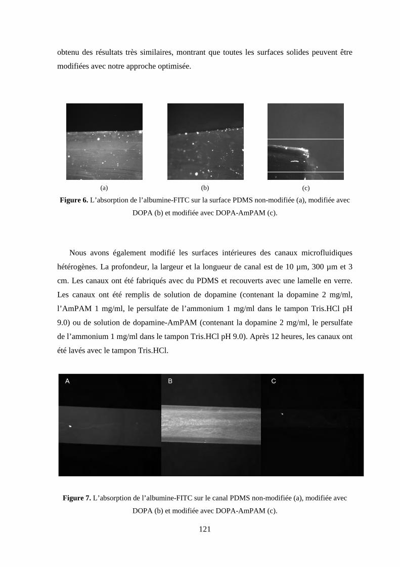
121
obtenu des résultats très similaires, montrant que toutes les surfaces solides peuvent être
modifiées avec notre approche optimisée.
(a)
(b)
(c)
Figure 6. L’absorption de l’albumine-FITC sur la surface PDMS non-modifiée (a), modifiée avec
DOPA (b) et modifiée avec DOPA-AmPAM (c).
Nous avons également modifié les surfaces intérieures des canaux microfluidiques
hétérogènes. La profondeur, la largeur et la longueur de canal est de 10 µm, 300 µm et 3
cm. Les canaux ont été fabriqués avec du PDMS et recouverts avec une lamelle en verre.
Les canaux ont été remplis de solution de dopamine (contenant la dopamine 2 mg/ml,
l’AmPAM 1 mg/ml, le persulfate de l’ammonium 1 mg/ml dans le tampon Tris.HCl pH
9.0) ou de solution de dopamine-AmPAM (contenant la dopamine 2 mg/ml, le persulfate
de l’ammonium 1 mg/ml dans le tampon Tris.HCl pH 9.0). Après 12 heures, les canaux ont
été lavés avec le tampon Tris.HCl.
Figure 7. L’absorption de l’albumine-FITC sur le canal PDMS non-modifiée (a), modifiée avec
DOPA (b) et modifiée avec DOPA-AmPAM (c).

122
Pour l’adsorption des protéines, les canaux non-modifiés, ceux modifiés avec DOPA
ou avec DOPA-AmPAM ont été rincés pendant deux heures (débit 10µl/s) avec la solution
de FITC-BSA dissoute dans le tampon PBS (pH 7.4) à une concentration de 0.3 mg/ml. La
solution de FITC-BSA a été laissée dans les canaux pendant 12 heures et, par conséquent,
les canaux ont été rincés par la solution de PBS pendant 30 minutes (débit 10µl/s). Une
fluorescence résiduelle a été observée sur la surface non-modifiée et la surface modifiée
avec DOPA, alors qu’elle est beaucoup plus faible sur les surfaces de DOPA-AmPAM (la
figure 7). Ces résultats sont en adéquation avec ceux de l’étude précédente effectuée sur les
surfaces plates de PDMS et de SU8.
4. Conclusion
Dans ce mémoire, une technologie simple et nouvelle a été développée pour contrôler
les propriétés des surfaces dans les dispositifs micro- / nano- fluidiques. Cette technologie
utilise la chimie de surface inspirée des moules qui permettra le greffage des brosses de
polymères hydrophiles sur toutes les surfaces dans un régime à faible viscosité.
L’utilisation d’un oxydant par une voie one-pot a nous permis à appliquer notre protocole à
modifier des surfaces dans les systèmes hétérogène micro- / nano- fluidiques. Les quatre
avantages de notre approche sont exposés : (i) l’indépendance aux substrats ; (ii) la
compatibilité avec des molécules biologiques telles que les enzymes, (iii) la facilité de
régénération et (iv) la capacité à fonctionner dans un régime à faible viscosité (paramètre
important pour l’utilisation des canaux à l’échelle sous-micromètre).
Nous avons synthétisé plusieurs chaînes de polymères (AmPAM et AmPNIPAM) en
utilisant le système redox cystéamine / persulfate de potassium. La structure des polymères
synthétisés a été caractérisée par FTIR, RMN et MALDI-TOF. La présence de l’amine
terminale des polymères (AmPAM et AmPNIPAM) a été évaluée par la conjugaison des
chaînes polymères avec l’analyse FITC et par la réaction avec l'acide acrylique,
respectivement. Le poids moléculaire des polymères a été déterminé par MALDI-TOF et
SEC. Les résultats de la SEC ont été jugés plus fiables que ceux des analyses MALDI-
TOF, en raison de la difficulté d’ionisation des fragments de polymères avec le MALDI-
TOF. Le protocole de polymérisation choisi a permis de synthétiser des polymères bien
structurés, possédant un groupement amine terminal et de poids moléculaire contrôlé. Par
conséquent, ces polymères ont pu être utilisés pour la fonctionnalisation de surfaces avec
des brosses de polymères.

123
Les conditions d’oxydation de la dopamine sont mises aux points afin de améliorer la
qualité de la couche contenant DOPA. Les propriétés des films de DOPA ont été étudiées
en fonction des différentes conditions d’oxydation. Les surfaces modifiées ont été étudiées
par des mesures d’angle de contact avec l’eau et par microscopie à force atomique.
L’augmentation de la vitesse de dépôt, dépendant de la vitesse d’oxydation, a permis
d’améliorer la qualité des surfaces. En effet, on a observé une rugosité réduite et beaucoup
moins d’agrégations en utilisant un oxydant. Des études approfondies de la cinétique de
dépôt pourraient être menées afin de comprendre la différence des mécanismes de dépôt en
présence et en absence d’oxydant. Dans cette étude, nous avons choisi l’oxydation induite
par l’oxydant (ammonium persulfate) pour optimiser la formation des films de DOPA.
Dans les systèmes microfluidiques pour lesquels le contrôle de l’écoulement de l’oxygène
est extrêmement difficile, l’utilisation de l’oxydant au lieu de l’oxygène facilite les
manipulations.
Nous avons greffe des brosses de polymère hydrophile (AmPAM) sur la surface dans
les conditions optimisé d’oxydation de la dopamine. Les substrats sont simplement plongés
dans une solution one-pot (contenant la dopamine, l’AmPAM et l’oxydant) pour former
une couche de polymère sur eux. Les substrats modifiés ont étudiés par des techniques
d’analyse de surface : l’angle de contact avec l’eau, microscopie à force atomique,
voltampérométrie cyclique et l’adsorption de protéines. Les résultats d’angle de contact
nous montrent que le polymère adhère à toutes les surfaces étudiées. Les
voltampérogrammes nous indique que les couches organiques (DOPA et / ou DOPA-
AmPAM) ont bien couvert les électrodes et empêchent la pénétration des espèces électro-
actives à la surface de l’électrode. L’étude de l’adsorption de protéines a confirmé la
propriété de non-encrassement (anti-fouling en anglais) de la surface modifiée avec le
DOPA-AmPAM. Ceci provient de la formation d’une barrière entropique par les brosses
de polymère.

124
Références
[1] S. Charlot, A.M. Gué, J. Tasselli, A. Marty, P. Abgrall, D. Estève, J. Micromech.
Microeng., 2008, 18(1), pp 1–8.
[2] Patrick Tabeling, Introduction to Microfluidics, Oxford University Press, UK (2005).
[3] H. Lee, S.M. Pellatore, P.B. Messersmith, Science, 2007, 318, pp 426–430.
[4] G.S Heather, F.R. Francisco, Mar. Biotechnol., 2007, 9(6), pp 661–681.
[5] Alain Durand, Dominique Hourdet, Polymer, 1999, 40 (17), pp 4941–4951.
[6] F. Bernsmann, A. Ponche, C. Ringwald, J. Hemmerlé, J. Raya, B. Bechinger, J.C.
Voegel, P. Schaaf, V. Ball, J. Phys. Chem. C, 2009, 113(19), pp 8234–8242.
[7] (a) P.G. De Gennes, J. Physic Paris, 1976, 37, pp 1445–1452 ; (b) S. Alexander, Physic
Paris, 1977, 38(8), pp 977–981.