TWO HANDLE WALL-MOUNT LAVATORY FAUCET GRIFO DE DOS ... · Todas las dimensiones y dibujos sirven...
6
IOG 2222.50 Rev. 3 January 2009 1 Dear Customer Estimado Cliente Thank you for selecting our product. We are confident we can fully satisfy Muchas gracias por elegir nuestro producto. Estamos seguros que podemos your expectations by offering you a wide range of technologically advanced satisfacer completamente sus expectativas ofreciéndole una amplia variedad products which directly result from our many years of experience in faucet de productos tecnológicamente avanzados que resultan directamente de and fitting production. muchos años de experiencia en grifos y su producción apropiada. ENGLISH ~ ESPANOL Model Modelo TARGA 3630-C14W Model Modelo SADE 1830-C14W For easy installation of your Para la instalación fácil de su grifo GRAFF faucet you will need: de la GRAFF usted necesitará: to READ ALL the instructions completely before beginning, LEER TODAS las instrucciones completamente antes de comenzar, to READ ALL the warnings, care and maintenance information. LEER TODA la información sobre las advertencias, cuidado y To complete the project, you should: mantenimiento. gather the tools and all the parts you will need, Para terminar el proyecto, usted debe: prepare the mounting area, recolectar las herramientas y todas las piezas que usted necesitará, mount the faucet, prepare el área para el montaje, connect the supply lines, monte el grifo, finally test and flush the faucet. conecte las líneas de fuente, You should have the following tools: finalmente pruebe y limpie el grifo con un chorro de agua. adjustable wrench, Usted debe tener las herramientas siguientes: channel pliers, llave ajustable, hex key (included in the box). alicates acanalados, llave hexagonal (incluido en la caja). l l l l l l l l l l l l l l l l l l l l ENGLISH ENGLISH ~ ESPANOL ~ ESPANOL FLOW RATE INFORMATION INFORMACIÓN DE INTENSIDAD DE FLUJO Maximum flow rate: 2.2 gpm (8.3l/min.) at 60 psi (4.1 bar) Flujo máximo 2.2 gpm (8.3l/min.) con 60 psi (4.1 bar) l l 3" (76mm) 8-1/2" (216mm) 2-23/64" (60mm) 2-23/64" (60mm) 1-3/16" (48mm) HOT CALIENTE (1/2-14 NPT) COLD FRÍA (1/2-14 NPT) 3-1/2" (89mm) min. 3-25/64" (86mm) max. 4-19/32" (116.5mm) 8-17/64" (210mm) 7-31/64" (190mm) 1/2-14 NPT 3-5/64" (78mm) 7- 8" (200mm) 7/ For care, use soft towel with soap and water only! Under no circumstances should you use any chemicals. ATTENTION! ATENCIÓN! Para el cuidado, utilice solamente una toalla suave con jabón y aqua! Bajo ninguna circunstancia no use productos químicos. 3" (76mm) 8-1/2" (216mm) 2-23/64" (60mm) 2-23/64" (60mm) 1-3/16" (48mm) HOT CALIENTE (1/2-14 NPT) COLD FRÍA (1/2-14 NPT) 3-1/2" (89mm) 2-13/32" (61mm) min. 3-25/64" (86mm) max. 4-19/32" (116.5mm) 8-5/64" (205mm) 7-7/8" (200mm) 1/2-14 NPT 3-5/64" (78mm) 7- 8" (200mm) 7/ This faucet complies with ASME/ANSI A112.18.1 and CSA B 125 Standards. Este grifo se encuentra conforme con losestandares de ASME/ANSI A112.18.1 y de CSA B 125. Installation Instructions l Instrucciones de Instalación TWO HANDLE WALL-MOUNT LAVATORY FAUCET GRIFO DE DOS MANILLAS MONTADOS EN LA PARED
Transcript of TWO HANDLE WALL-MOUNT LAVATORY FAUCET GRIFO DE DOS ... · Todas las dimensiones y dibujos sirven...

IOG 2222.50 Rev. 3 January 20091
Dear Customer Estimado ClienteThank you for selecting our product. We are confident we can fully satisfy Muchas gracias por elegir nuestro producto. Estamos seguros que podemos your expectations by offering you a wide range of technologically advanced satisfacer completamente sus expectativas ofreciéndole una amplia variedad products which directly result from our many years of experience in faucet de productos tecnológicamente avanzados que resultan directamente de and fitting production. muchos años de experiencia en grifos y su producción apropiada.
ENGLISH~
ESPANOL
ModelModelo TARGA 3630-C14W
ModelModelo SADE 1830-C14W
For easy installation of your Para la instalación fácil de su grifo GRAFF faucet you will need: de la GRAFF usted necesitará:
to READ ALL the instructions completely before beginning, LEER TODAS las instrucciones completamente antes de comenzar,to READ ALL the warnings, care and maintenance information. LEER TODA la información sobre las advertencias, cuidado y
To complete the project, you should: mantenimiento.gather the tools and all the parts you will need, Para terminar el proyecto, usted debe:prepare the mounting area, recolectar las herramientas y todas las piezas que usted necesitará,mount the faucet, prepare el área para el montaje,connect the supply lines, monte el grifo,finally test and flush the faucet. conecte las líneas de fuente,
You should have the following tools: finalmente pruebe y limpie el grifo con un chorro de agua.adjustable wrench, Usted debe tener las herramientas siguientes:channel pliers, llave ajustable,hex key (included in the box). alicates acanalados,
llave hexagonal (incluido en la caja).
l l
l l
l
l l
l l
l l
l l
l
l
l l
l l
l
ENGLISH
ENGLISH
~
ESPANOL
~
ESPANOL
FLOW RATE INFORMATION INFORMACIÓN DE INTENSIDAD DE FLUJO
Maximum flow rate: 2.2 gpm (8.3l/min.) at 60 psi (4.1 bar) Flujo máximo 2.2 gpm (8.3l/min.) con 60 psi (4.1 bar)l l
3" (76mm)
8-1/2" (216mm)
2-23/64" (60mm)
2-2
3/6
4"
(60m
m)
1-3
/16"
(48m
m)
HOTCALIENTE
(1/2-14 NPT)
COLDFRÍA
(1/2-14 NPT)
3-1
/2"
(89m
m)
min. 3-25/64" (86mm)
max. 4-19/32" (116.5mm)
8-17/64" (210mm)
7-31/64" (190mm)
1/2-14 NPT
3-5/64" (78mm)
7- 8" (200mm)7/
For care, use soft towel with soap and water only! Under nocircumstances should you use any chemicals.ATTENTION! ATENCIÓN!
Para el cuidado, utilice solamente una toalla suave con jabón y aqua! Bajo ninguna circunstancia no use productos químicos.
3" (76mm)
8-1/2" (216mm)
2-23/64" (60mm)
2-2
3/6
4"
(60m
m)
1-3
/16"
(48m
m)
HOTCALIENTE
(1/2-14 NPT)
COLDFRÍA
(1/2-14 NPT)
3-1
/2"
(89m
m)
2-13/32" (61mm)min. 3-25/64"
(86mm)
max. 4-19/32" (116.5mm)
8-5/64" (205mm)
7-7/8" (200mm)1/2-14 NPT
3-5/64" (78mm)
7- 8" (200mm)7/
This faucet complies with ASME/ANSI A112.18.1and CSA B 125 Standards.Este grifo se encuentra conforme con losestandaresde ASME/ANSI A112.18.1 y de CSA B 125.
Installation Instructions l Instrucciones de Instalación
TWO HANDLE WALL-MOUNT LAVATORY FAUCETGRIFO DE DOS MANILLAS MONTADOS EN LA PARED
This faucet complies with ASME/ANSI A112.18.1and CSA B 125 Standards.Este grifo se encuentra conforme con losestandaresde ASME/ANSI A112.18.1 y de CSA B 125.
Installation Instructions l Instrucciones de Instalación
TWO HANDLE WALL-MOUNT LAVATORY FAUCETGRIFO DE DOS MANILLAS MONTADOS EN LA PARED
All dimensions and drawings are for reference only. For details, please refer to actual products.
Todas las dimensiones y dibujos sirven únicamente de referencia. Para consultar detalles, ver los productos.
ENGLISH~
ESPANOL
4CARE AND MAINTENANCE l CUIDADO Y MANTENIMIENTO
Your Graff faucet is designed and engineered in accordance with Su grifo de la Graff esta diseñado y dirigido acuerdo con los the highest quality and performance standards. Be sure not to estándares de funcionamiento y calidad más altos. Este seguro no damage the finish during installation. Care should be given to the dañar las terminaciones del grifo durante la instalación. Cuide el cleaning of this product. Although its finish is extremely durable, it producto manteniendolo siempre limpio. Aunque su acabado es can be damaged by harsh abrasives or polish. Never use extremadamente durable, puede ser dañado por los abrasivos o abrasive cleaners, acids, solvents, etc. to clean any Graff pulientes ásperos. Nunca utilice limpiadores abrasivos, ácidos, product. To clean, simply wipe gently with a damp cloth and solventes, el etc. para limpiar cualquier producto de la Graff. blot dry with a soft towel. Para limpiar, simplemente use un paño húmedo y seque con
una toalla suave.
ENGLISH~
ESPANOL
WARRANTY l GARANTÍA
Warranty conditions and warranty registration card are outlined on a Las condiciones de la garantía y la tarjeta del registro de la garantía separate sheet. se encuentran en una pagina separada.
IOG 2222.50 Rev. 3 January 20096
This faucet complies with ASME/ANSI A112.18.1and CSA B 125 Standards.Este grifo se encuentra conforme con losestandaresde ASME/ANSI A112.18.1 y de CSA B 125.
Installation Instructions l Instrucciones de Instalación
TWO HANDLE WALL-MOUNT LAVATORY FAUCETGRIFO DE DOS MANILLAS MONTADOS EN LA PARED
SET-UP DIAGRAM l DIAGRAMA DE INSTALACIÓN
IOG 2222.50 Rev. 3 January 20092
Finished wallAcabado de la pared
7- 8" (200mm)7/
1-49/64"(45mm)
3-5/64" (78mm)
2-5
/32"
(55m
m)
3-1
/2"
(89m
m)
2-5
1/6
4"
(71m
m)
Ø13/64" (Ø5mm)
3" (76mm)
Ø7/8" (Ø22mm)
13/3
2"
(10.5
mm
)
1-3/16" (48mm)
1-3
/16"
(48m
m)
1-3/16" (48mm)
Ø1-11/32" (Ø34mm)
Ø1-7/32" (Ø31mm)
Ø7/(Ø22mm)
8" Ø
( 34mm)
1-11/32" Ø
Ø( 31mm)
1-7/32" Ø
4-4
5/6
4"
(119.5
mm
)
MIN
. 3-2
5/6
4"
(86m
m)
MIN
. 2-4
5/6
4"
(68.5
mm
)
63/6
4"
(25m
m)
MAX.
4-1
9/3
2"
(116.5
mm
)
MAX.
3-2
9/3
2"
(99m
m)
REMOVE OLD FAUCETTurn off the water supplies (hot and cold water).Disconnect supply lines and remove old faucet.Clean the sink surface of putty, dirt., etc.
BEFORE INSTALLINGBefore installing the faucet, it is good to rinse the supply pipelines in order to do away with the dirty residues.We recommend installing the filter taps.
QUITE EL GRIFO VIEJOLimpie las tuberias a fondo y cierre las llaves de suministro de agua (agua caliente y fría).Desconecte las líneas de suministro y quite el grifo viejo.Limpie la superficie del fregadero de la masilla, suciedad, etc.
ANTES DE LA INSTALACIÓNAntes de instalar el grifo, es bueno ejuagar las tuberías suministro para eliminar residuos.Recomendamos el instalar los tapones de filtro.
l
l
l
l
l
l
l
l
l
l
1
ENGLISH
~
ESPANOL
This faucet complies with ASME/ANSI A112.18.1and CSA B 125 Standards.Este grifo se encuentra conforme con losestandaresde ASME/ANSI A112.18.1 y de CSA B 125.
Installation Instructions l Instrucciones de Instalación
TWO HANDLE WALL-MOUNT LAVATORY FAUCETGRIFO DE DOS MANILLAS MONTADOS EN LA PARED
IOG 2222.50 Rev. 3 January 20093
ENGLISH
ENGLISH~
ESPANOL
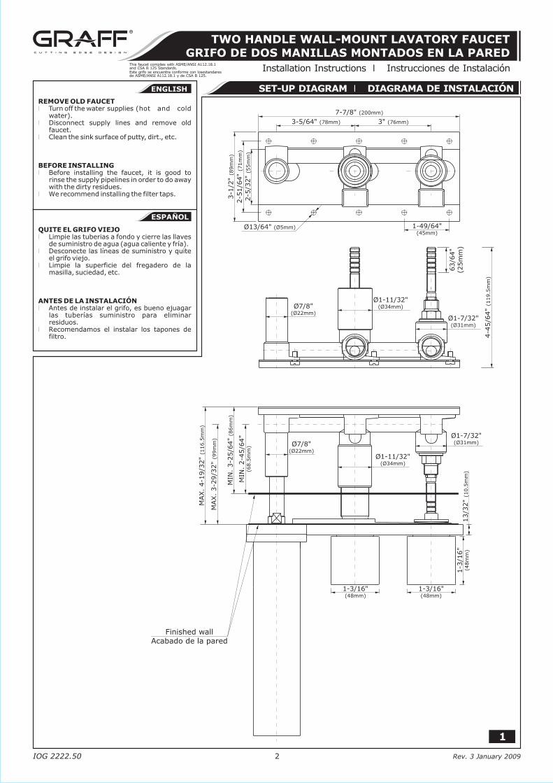
SPOUT
AERATOR INSERT
TUBE OF SPOUT
SEAL O-RING
PLATE
CONNECTOR
LEFT HANDLE C14B
(hot water)
RIGHT HANDLE
(cold water)
SET SCREW
SCREW
SPOUT SLEEVE
SLEEVE
CLOCKWISE OPENING
CARTRIDGE
FAUCET BODY UNIT
MOUNTING PLATE
SPECIAL HEX KEY
(for CONNECTOR (6))
SPECIAL HEX KEY
(for CARTRIDGE (13))
HEX KEY
C14W
1
2
3
4
5
6
7
8
9
10
11
12
13
14
15
A
B
C
CAÑO
INSERTOR DEL AEREADOR
TUBERIA DE CAÑO
SELLADOR DE ANILLO (O-RING)
PLAQUILLA
CONECTADOR
MANILLA IZQUIERDA
(agua caliente)
MANILLA DERECHA
(agua fría)
TORNILLO DEL BOQUEO
TORNILLO
CASQUILLO DEL CAÑO
CASQUILLO
CARTUCHO QUE SE ABRE HACIA
LA DERECHA
UNIDAD DEL CUERPO DEL GRIFO
PLAQUILLA DE MONTAJE
LLAVE HEXAGONAL ESPECIAL
(para el CONECTADOR (6))
LLAVE HEXAGONAL ESPECIAL
(para el CARTUCHO (13))
LLAVE HAXAGONAL
C14B
C14W
12
13
14
11
4
3
1
6
7
2
A B C
9 10
2:1
5
8
1-3
1/3
2"
(50m
m)
4-1
7/3
2"
(115m
m)
35/6
4"
(14m
m)
21/3
2"
(17m
m) 3/32"
(2.5mm)
2-1
3/6
4"
(56m
m)
CARTRID
GE A
SSEM
BLY
BLO
CK
EL B
LO
QU
E D
E C
ABEZAS
SPO
UT A
SSEM
BLY
BLO
CK
EL B
LO
QU
E D
E C
AÑ
O
2
This faucet complies with ASME/ANSI A112.18.1and CSA B 125 Standards.Este grifo se encuentra conforme con losestandaresde ASME/ANSI A112.18.1 y de CSA B 125.
Installation Instructions l Instrucciones de Instalación
TWO HANDLE WALL-MOUNT LAVATORY FAUCETGRIFO DE DOS MANILLAS MONTADOS EN LA PARED
2ROUGH-IN INSTALLATION l INSTALACIÓN ANTES DEL ENLUCIDO
3FAUCET INSTALLATION l INSTALACIÓN DEL GRIFO
IOG 2222.50 Rev. 3 January 20094
4.1
12
13
11
4
3
1
6 8
CUTCORTE
4.2
1211
4
3
1 A
65
8
HOT WATER INLETENTRADA DE AGUA CALIENTE
COLD WATER INLETENTRADA DE AGUA FRÍA
See fig. 3Prepare the recess in the wall for the faucet body unit pipe work
taking into account the maximum and minimum depth allowed. Arrange the pipe work so that the hot water feed is underneath the body (HOT) and the cold in on the right (COLD) in relation to the faucet body unit.
Place faucet body unit into the wall recess. Recommended depth for faucet body unit in a wall measured from center of faucet body unit to finished wall surface is in the range MIN. 2-45/64” (68.5mm) – MAX. 3-29/32” (99mm). Attach the faucet body unit to the wall using the anchors and screws.
Apply thread sealant to the pipe nipple threads of 1/2" pipe connectors. Screw in a 1/2" pipe connectors onto faucet body unit inlets. Connect HOT water supply to underneath left valve inlet and COLD water supply to right valve inlet.
Vea dis. 3Preparar un agujero en la pared para las tuberías del cuerpo del grifo
tomando en consideración la profundidad máxima y mínima admisible. Instalar los tubos de tal manera que la fuente del agua caliente se encuentre por debajo del cuerpo (HOT) y del agua fría a la derecha (COLD) en relación al cuerpo del grifo.
Colocar el cuerpo del grifo en el agujero de la pared. La profundidad recomendada para la unidad del cuerpo del grifo en la pared, medida desde el centro del cuerpo del grifo hasta la superficie de la pared acabada es de MIN. 2-45/64” (68.5mm) y MAX. 3-29/32” (99mm). Fijar el cuerpo del grifo a la pared usando anclajes y tornillos.
Usar la junta de rosca para el manguito roscado del tubo de 1/2". Enroscar los manguitos del tubo de 1/2" a los orificios de entrada al cuerpo de grifo. Conectar el suministro del agua CALIENTE a la entrada inferior izquierda de la válvula y del agua FRÍA a la entrada derecha de la válvula.
ENGLISH
~
ESPANOL
3
This faucet complies with ASME/ANSI A112.18.1and CSA B 125 Standards.Este grifo se encuentra conforme con losestandaresde ASME/ANSI A112.18.1 y de CSA B 125.
Installation Instructions l Instrucciones de Instalación
TWO HANDLE WALL-MOUNT LAVATORY FAUCETGRIFO DE DOS MANILLAS MONTADOS EN LA PARED
ENGLISH~
ESPANOL
IOG 2222.50 Rev. 3 January 20095
4.4
9
C
1211
12:1
D
D
7
7
8
5
D = 0.035" (0.9mm) ÷ 0.047" (1.2mm)
4.3
12
5
11
1 7
7
C C
7.1
8
RO
TATE P
LASTIC
RIN
G (
7.1
)G
IRE T
OD
O E
L A
NIL
LO
(7.1
)
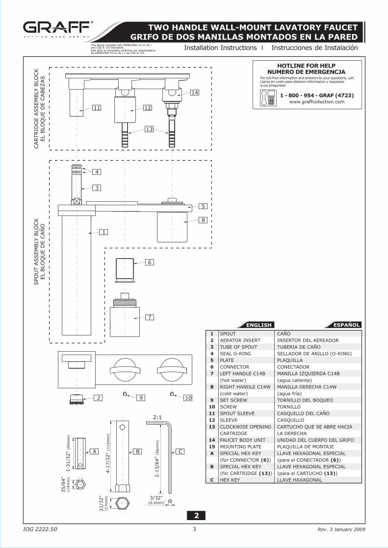
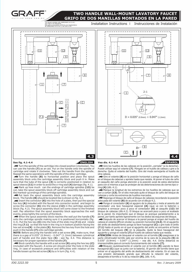
Turn the spindle of the cartridge into closed position (clockwise). You Gire los husillos de las cabezas en la posición „cerrada” (a la derecha). can use the handle (7) as an aid. Put on the handle onto the spindle of Puede utilizar aquí el volante (7). Póngalo en el husillo de cabeza y gire a la cartridge and rotate it clockwise. Take out the handle from the spindle. derecha. Quite el volante del husillo. Gire del modo semejante el husillo de Repeat the same operations with the spindle of the other cartridge. otra cabeza.
Turn the handle (8) to horizontal position and place the spout Gire el volante (8) en la posición horizontal y ponga el bloque de caño assembly block onto the cartridge assembly block and push it in. Make en el bloque de cabezas y apriete hasta que resista. Al poner el tubo de caño sure that the tube of the spout (3) is correctly positioned in relation to al casquillo del caño ponga atención a la posición axial de estos elementos spout sleeve (11) in order to avoid the o-ring seal (4) damage (fig. 4.1). para con sí mismos a que se protejan de las deterioraciones de cierres tipo o-
Mark up how much can the endings of cartridge spindles (13) be ring (4) (dib. 4.1).cut, take the spout assembly block off cartridge assembly block and cut Marque la longitud de los extremos de los husillos de cabezas que se the marked-up endings of the cartridge spindles. van a cortan (13). En el sitio marcado quite el bloque de caño del bloque de
Put back the spout assembly block onto the cartridge assembly cabezas y corte los extremos de husillos marcados.block. The handle (8) should be located like is shown on fig. 4.2. Reponga el bloque de caño al bloque de cabezas recordando la posición
Insert the connector (6) into the hole of a plate, then put the special adecuada del volante (8) de acuerdo con el dibujo 4.2.hex key (A) included with the faucet into connector socket and begin to Ponga el conectador (6) al agujero de la plaquita y meta al asiento del screw the connector (6) into the sleeve (12) in the cartridge assembly conectador una lave haxagonal especial (A) (que va con la batería) y block (fig. 4.2). The spout assembly block will come closer to the finished empiece a enroscar poco a poco el conectador (6) al casquillo (12) del wall. Pay attention that the spout assembly block approaches the wall bloque de cabezas (dib.4.2). El bloque se acercará poco a poco al acabado evenly, press lightly the corners of the block. de la pared. Es importante que el bloque se acerque paralelamente a la
When the spout assembly block reaches the wall put the handle (7) pared, por tanto apriete ligeramente con los dedos las esquinas del bloque.onto the cartridge spindle making sure it is positioned horizontally (fig. Después de acercar el bloque a la pared ponga al origen del husillo de 4.3). Put the hex key (C) into the hole of the slide ring (7.1) and rotate cabeza el volante (7) sin olvidar su posición horizontal (4.3). En el agujerito the ring (7.1) so that the hole in the ring is in bottom position facing the del anillo de deslizamiento ponga la llave haxagonal (C) y gire todo el anillo hex set screw(9) in the plate (5). Remove the hex key from the hole and (7.1) hasta el punto en el que el agujerito del anillo se encuentre al frente push in the handle (7) onto cartridge spindle. del tornillo del boqueo (9) en la plaquilla. Quite la llave haxagonal del NOTE: Before securing the handle with a set screw (9), make sure, that agujerito y ponga el volante (7) al husillo de cabeza hasta que resista. there is a gap of 0.035” (0.9mm) – 0.047” (1.2mm) between cylindrical ATENCIÓN: Antes de bloquear el volante con el tornillo (9) asegúrese si la part of handle and the plate face (5) - see fig. 4.4. This distance is parte cilíndricadel tornillo sale por encima de la cara de la plaquilla (5) de necessary for proper operation of the handle (7). 0.035” (0.9mm) – 0.047” (1.2mm) – vea dib. 4.4. Dicha distancia es
Block carefully the handle with a set screw (9) using the hex key (C) imprescindible para el correcto funcionamiento del volante (7).(included with the faucet). A screw pin should enter the hole in the slide Bloquee cautelosamente el volante con el tornillo (9) usando la llave ring. In case of excessive pressure and difficulties with rotation of the haxagonal (C) (que va junto con la batería). El gorrón del tornillo tiene que handle loosen up the set screw (9) by a ¼ turn (fig. 4.4). entrar en el agujerito del anillo de deslizamiento del volante. En el caso de
una presión demasiado grande que dificulte la retación del volante, desapriete el tornillo a ¼ de su rotación (9), (dib. 4.4).
See fig. 4.1-4.4 Vea dis. 4.1-4.4
IOG 2222.50 Rev. 3 January 20091
Dear Customer Estimado ClienteThank you for selecting our product. We are confident we can fully satisfy Muchas gracias por elegir nuestro producto. Estamos seguros que podemos your expectations by offering you a wide range of technologically advanced satisfacer completamente sus expectativas ofreciéndole una amplia variedad products which directly result from our many years of experience in faucet de productos tecnológicamente avanzados que resultan directamente de and fitting production. muchos años de experiencia en grifos y su producción apropiada.
ENGLISH~
ESPANOL
ModelModelo TARGA 3630-C14W
ModelModelo SADE 1830-C14W
For easy installation of your Para la instalación fácil de su grifo GRAFF faucet you will need: de la GRAFF usted necesitará:
to READ ALL the instructions completely before beginning, LEER TODAS las instrucciones completamente antes de comenzar,to READ ALL the warnings, care and maintenance information. LEER TODA la información sobre las advertencias, cuidado y
To complete the project, you should: mantenimiento.gather the tools and all the parts you will need, Para terminar el proyecto, usted debe:prepare the mounting area, recolectar las herramientas y todas las piezas que usted necesitará,mount the faucet, prepare el área para el montaje,connect the supply lines, monte el grifo,finally test and flush the faucet. conecte las líneas de fuente,
You should have the following tools: finalmente pruebe y limpie el grifo con un chorro de agua.adjustable wrench, Usted debe tener las herramientas siguientes:channel pliers, llave ajustable,hex key (included in the box). alicates acanalados,
llave hexagonal (incluido en la caja).
l l
l l
l
l l
l l
l l
l l
l
l
l l
l l
l
ENGLISH
ENGLISH
~
ESPANOL
~
ESPANOL
FLOW RATE INFORMATION INFORMACIÓN DE INTENSIDAD DE FLUJO
Maximum flow rate: 2.2 gpm (8.3l/min.) at 60 psi (4.1 bar) Flujo máximo 2.2 gpm (8.3l/min.) con 60 psi (4.1 bar)l l
3" (76mm)
8-1/2" (216mm)
2-23/64" (60mm)
2-2
3/6
4"
(60m
m)
1-3
/16"
(48m
m)
HOTCALIENTE
(1/2-14 NPT)
COLDFRÍA
(1/2-14 NPT)
3-1
/2"
(89m
m)
min. 3-25/64" (86mm)
max. 4-19/32" (116.5mm)
8-17/64" (210mm)
7-31/64" (190mm)
1/2-14 NPT
3-5/64" (78mm)
7- 8" (200mm)7/
For care, use soft towel with soap and water only! Under nocircumstances should you use any chemicals.ATTENTION! ATENCIÓN!
Para el cuidado, utilice solamente una toalla suave con jabón y aqua! Bajo ninguna circunstancia no use productos químicos.
3" (76mm)
8-1/2" (216mm)
2-23/64" (60mm)
2-2
3/6
4"
(60m
m)
1-3
/16"
(48m
m)
HOTCALIENTE
(1/2-14 NPT)
COLDFRÍA
(1/2-14 NPT)
3-1
/2"
(89m
m)
2-13/32" (61mm)min. 3-25/64"
(86mm)
max. 4-19/32" (116.5mm)
8-5/64" (205mm)
7-7/8" (200mm)1/2-14 NPT
3-5/64" (78mm)
7- 8" (200mm)7/
This faucet complies with ASME/ANSI A112.18.1and CSA B 125 Standards.Este grifo se encuentra conforme con losestandaresde ASME/ANSI A112.18.1 y de CSA B 125.
Installation Instructions l Instrucciones de Instalación
TWO HANDLE WALL-MOUNT LAVATORY FAUCETGRIFO DE DOS MANILLAS MONTADOS EN LA PARED
This faucet complies with ASME/ANSI A112.18.1and CSA B 125 Standards.Este grifo se encuentra conforme con losestandaresde ASME/ANSI A112.18.1 y de CSA B 125.
Installation Instructions l Instrucciones de Instalación
TWO HANDLE WALL-MOUNT LAVATORY FAUCETGRIFO DE DOS MANILLAS MONTADOS EN LA PARED
All dimensions and drawings are for reference only. For details, please refer to actual products.
Todas las dimensiones y dibujos sirven únicamente de referencia. Para consultar detalles, ver los productos.
ENGLISH~
ESPANOL
4CARE AND MAINTENANCE l CUIDADO Y MANTENIMIENTO
Your Graff faucet is designed and engineered in accordance with Su grifo de la Graff esta diseñado y dirigido acuerdo con los the highest quality and performance standards. Be sure not to estándares de funcionamiento y calidad más altos. Este seguro no damage the finish during installation. Care should be given to the dañar las terminaciones del grifo durante la instalación. Cuide el cleaning of this product. Although its finish is extremely durable, it producto manteniendolo siempre limpio. Aunque su acabado es can be damaged by harsh abrasives or polish. Never use extremadamente durable, puede ser dañado por los abrasivos o abrasive cleaners, acids, solvents, etc. to clean any Graff pulientes ásperos. Nunca utilice limpiadores abrasivos, ácidos, product. To clean, simply wipe gently with a damp cloth and solventes, el etc. para limpiar cualquier producto de la Graff. blot dry with a soft towel. Para limpiar, simplemente use un paño húmedo y seque con
una toalla suave.
ENGLISH~
ESPANOL
WARRANTY l GARANTÍA
Warranty conditions and warranty registration card are outlined on a Las condiciones de la garantía y la tarjeta del registro de la garantía separate sheet. se encuentran en una pagina separada.
IOG 2222.50 Rev. 3 January 20096
This faucet complies with ASME/ANSI A112.18.1and CSA B 125 Standards.Este grifo se encuentra conforme con losestandaresde ASME/ANSI A112.18.1 y de CSA B 125.
Installation Instructions l Instrucciones de Instalación
TWO HANDLE WALL-MOUNT LAVATORY FAUCETGRIFO DE DOS MANILLAS MONTADOS EN LA PARED
SET-UP DIAGRAM l DIAGRAMA DE INSTALACIÓN
IOG 2222.50 Rev. 3 January 20092
Finished wallAcabado de la pared
7- 8" (200mm)7/
1-49/64"(45mm)
3-5/64" (78mm)
2-5
/32"
(55m
m)
3-1
/2"
(89m
m)
2-5
1/6
4"
(71m
m)
Ø13/64" (Ø5mm)
3" (76mm)
Ø7/8" (Ø22mm)
13/3
2"
(10.5
mm
)
1-3/16" (48mm)
1-3
/16"
(48m
m)
1-3/16" (48mm)
Ø1-11/32" (Ø34mm)
Ø1-7/32" (Ø31mm)
Ø7/(Ø22mm)
8" Ø
( 34mm)
1-11/32" Ø
Ø( 31mm)
1-7/32" Ø
4-4
5/6
4"
(119.5
mm
)
MIN
. 3-2
5/6
4"
(86m
m)
MIN
. 2-4
5/6
4"
(68.5
mm
)
63/6
4"
(25m
m)
MAX.
4-1
9/3
2"
(116.5
mm
)
MAX.
3-2
9/3
2"
(99m
m)
REMOVE OLD FAUCETTurn off the water supplies (hot and cold water).Disconnect supply lines and remove old faucet.Clean the sink surface of putty, dirt., etc.
BEFORE INSTALLINGBefore installing the faucet, it is good to rinse the supply pipelines in order to do away with the dirty residues.We recommend installing the filter taps.
QUITE EL GRIFO VIEJOLimpie las tuberias a fondo y cierre las llaves de suministro de agua (agua caliente y fría).Desconecte las líneas de suministro y quite el grifo viejo.Limpie la superficie del fregadero de la masilla, suciedad, etc.
ANTES DE LA INSTALACIÓNAntes de instalar el grifo, es bueno ejuagar las tuberías suministro para eliminar residuos.Recomendamos el instalar los tapones de filtro.
l
l
l
l
l
l
l
l
l
l
1
ENGLISH
~
ESPANOL
This faucet complies with ASME/ANSI A112.18.1and CSA B 125 Standards.Este grifo se encuentra conforme con losestandaresde ASME/ANSI A112.18.1 y de CSA B 125.
Installation Instructions l Instrucciones de Instalación
TWO HANDLE WALL-MOUNT LAVATORY FAUCETGRIFO DE DOS MANILLAS MONTADOS EN LA PARED
IOG 2222.50 Rev. 3 January 20093
ENGLISH
ENGLISH~
ESPANOL
SPOUT
AERATOR INSERT
TUBE OF SPOUT
SEAL O-RING
PLATE
CONNECTOR
LEFT HANDLE C14B
(hot water)
RIGHT HANDLE
(cold water)
SET SCREW
SCREW
SPOUT SLEEVE
SLEEVE
CLOCKWISE OPENING
CARTRIDGE
FAUCET BODY UNIT
MOUNTING PLATE
SPECIAL HEX KEY
(for CONNECTOR (6))
SPECIAL HEX KEY
(for CARTRIDGE (13))
HEX KEY
C14W
1
2
3
4
5
6
7
8
9
10
11
12
13
14
15
A
B
C
CAÑO
INSERTOR DEL AEREADOR
TUBERIA DE CAÑO
SELLADOR DE ANILLO (O-RING)
PLAQUILLA
CONECTADOR
MANILLA IZQUIERDA
(agua caliente)
MANILLA DERECHA
(agua fría)
TORNILLO DEL BOQUEO
TORNILLO
CASQUILLO DEL CAÑO
CASQUILLO
CARTUCHO QUE SE ABRE HACIA
LA DERECHA
UNIDAD DEL CUERPO DEL GRIFO
PLAQUILLA DE MONTAJE
LLAVE HEXAGONAL ESPECIAL
(para el CONECTADOR (6))
LLAVE HEXAGONAL ESPECIAL
(para el CARTUCHO (13))
LLAVE HAXAGONAL
C14B
C14W
12
13
14
11
4
3
1
6
7
2
A B C
9 10
2:1
5
8
1-3
1/3
2"
(50m
m)
4-1
7/3
2"
(115m
m)
35/6
4"
(14m
m)
21/3
2"
(17m
m) 3/32"
(2.5mm)
2-1
3/6
4"
(56m
m)
CARTRID
GE A
SSEM
BLY
BLO
CK
EL B
LO
QU
E D
E C
ABEZAS
SPO
UT A
SSEM
BLY
BLO
CK
EL B
LO
QU
E D
E C
AÑ
O
2
This faucet complies with ASME/ANSI A112.18.1and CSA B 125 Standards.Este grifo se encuentra conforme con losestandaresde ASME/ANSI A112.18.1 y de CSA B 125.
Installation Instructions l Instrucciones de Instalación
TWO HANDLE WALL-MOUNT LAVATORY FAUCETGRIFO DE DOS MANILLAS MONTADOS EN LA PARED
2ROUGH-IN INSTALLATION l INSTALACIÓN ANTES DEL ENLUCIDO
3FAUCET INSTALLATION l INSTALACIÓN DEL GRIFO
IOG 2222.50 Rev. 3 January 20094
4.1
12
13
11
4
3
1
6 8
CUTCORTE
4.2
1211
4
3
1 A
65
8
HOT WATER INLETENTRADA DE AGUA CALIENTE
COLD WATER INLETENTRADA DE AGUA FRÍA
See fig. 3Prepare the recess in the wall for the faucet body unit pipe work
taking into account the maximum and minimum depth allowed. Arrange the pipe work so that the hot water feed is underneath the body (HOT) and the cold in on the right (COLD) in relation to the faucet body unit.
Place faucet body unit into the wall recess. Recommended depth for faucet body unit in a wall measured from center of faucet body unit to finished wall surface is in the range MIN. 2-45/64” (68.5mm) – MAX. 3-29/32” (99mm). Attach the faucet body unit to the wall using the anchors and screws.
Apply thread sealant to the pipe nipple threads of 1/2" pipe connectors. Screw in a 1/2" pipe connectors onto faucet body unit inlets. Connect HOT water supply to underneath left valve inlet and COLD water supply to right valve inlet.
Vea dis. 3Preparar un agujero en la pared para las tuberías del cuerpo del grifo
tomando en consideración la profundidad máxima y mínima admisible. Instalar los tubos de tal manera que la fuente del agua caliente se encuentre por debajo del cuerpo (HOT) y del agua fría a la derecha (COLD) en relación al cuerpo del grifo.
Colocar el cuerpo del grifo en el agujero de la pared. La profundidad recomendada para la unidad del cuerpo del grifo en la pared, medida desde el centro del cuerpo del grifo hasta la superficie de la pared acabada es de MIN. 2-45/64” (68.5mm) y MAX. 3-29/32” (99mm). Fijar el cuerpo del grifo a la pared usando anclajes y tornillos.
Usar la junta de rosca para el manguito roscado del tubo de 1/2". Enroscar los manguitos del tubo de 1/2" a los orificios de entrada al cuerpo de grifo. Conectar el suministro del agua CALIENTE a la entrada inferior izquierda de la válvula y del agua FRÍA a la entrada derecha de la válvula.
ENGLISH
~
ESPANOL
3
This faucet complies with ASME/ANSI A112.18.1and CSA B 125 Standards.Este grifo se encuentra conforme con losestandaresde ASME/ANSI A112.18.1 y de CSA B 125.
Installation Instructions l Instrucciones de Instalación
TWO HANDLE WALL-MOUNT LAVATORY FAUCETGRIFO DE DOS MANILLAS MONTADOS EN LA PARED
ENGLISH~
ESPANOL
IOG 2222.50 Rev. 3 January 20095
4.4
9
C
1211
12:1
D
D
7
7
8
5
D = 0.035" (0.9mm) ÷ 0.047" (1.2mm)
4.3
12
5
11
1 7
7
C C
7.1
8
RO
TATE P
LASTIC
RIN
G (
7.1
)G
IRE T
OD
O E
L A
NIL
LO
(7.1
)
Turn the spindle of the cartridge into closed position (clockwise). You Gire los husillos de las cabezas en la posición „cerrada” (a la derecha). can use the handle (7) as an aid. Put on the handle onto the spindle of Puede utilizar aquí el volante (7). Póngalo en el husillo de cabeza y gire a la cartridge and rotate it clockwise. Take out the handle from the spindle. derecha. Quite el volante del husillo. Gire del modo semejante el husillo de Repeat the same operations with the spindle of the other cartridge. otra cabeza.
Turn the handle (8) to horizontal position and place the spout Gire el volante (8) en la posición horizontal y ponga el bloque de caño assembly block onto the cartridge assembly block and push it in. Make en el bloque de cabezas y apriete hasta que resista. Al poner el tubo de caño sure that the tube of the spout (3) is correctly positioned in relation to al casquillo del caño ponga atención a la posición axial de estos elementos spout sleeve (11) in order to avoid the o-ring seal (4) damage (fig. 4.1). para con sí mismos a que se protejan de las deterioraciones de cierres tipo o-
Mark up how much can the endings of cartridge spindles (13) be ring (4) (dib. 4.1).cut, take the spout assembly block off cartridge assembly block and cut Marque la longitud de los extremos de los husillos de cabezas que se the marked-up endings of the cartridge spindles. van a cortan (13). En el sitio marcado quite el bloque de caño del bloque de
Put back the spout assembly block onto the cartridge assembly cabezas y corte los extremos de husillos marcados.block. The handle (8) should be located like is shown on fig. 4.2. Reponga el bloque de caño al bloque de cabezas recordando la posición
Insert the connector (6) into the hole of a plate, then put the special adecuada del volante (8) de acuerdo con el dibujo 4.2.hex key (A) included with the faucet into connector socket and begin to Ponga el conectador (6) al agujero de la plaquita y meta al asiento del screw the connector (6) into the sleeve (12) in the cartridge assembly conectador una lave haxagonal especial (A) (que va con la batería) y block (fig. 4.2). The spout assembly block will come closer to the finished empiece a enroscar poco a poco el conectador (6) al casquillo (12) del wall. Pay attention that the spout assembly block approaches the wall bloque de cabezas (dib.4.2). El bloque se acercará poco a poco al acabado evenly, press lightly the corners of the block. de la pared. Es importante que el bloque se acerque paralelamente a la
When the spout assembly block reaches the wall put the handle (7) pared, por tanto apriete ligeramente con los dedos las esquinas del bloque.onto the cartridge spindle making sure it is positioned horizontally (fig. Después de acercar el bloque a la pared ponga al origen del husillo de 4.3). Put the hex key (C) into the hole of the slide ring (7.1) and rotate cabeza el volante (7) sin olvidar su posición horizontal (4.3). En el agujerito the ring (7.1) so that the hole in the ring is in bottom position facing the del anillo de deslizamiento ponga la llave haxagonal (C) y gire todo el anillo hex set screw(9) in the plate (5). Remove the hex key from the hole and (7.1) hasta el punto en el que el agujerito del anillo se encuentre al frente push in the handle (7) onto cartridge spindle. del tornillo del boqueo (9) en la plaquilla. Quite la llave haxagonal del NOTE: Before securing the handle with a set screw (9), make sure, that agujerito y ponga el volante (7) al husillo de cabeza hasta que resista. there is a gap of 0.035” (0.9mm) – 0.047” (1.2mm) between cylindrical ATENCIÓN: Antes de bloquear el volante con el tornillo (9) asegúrese si la part of handle and the plate face (5) - see fig. 4.4. This distance is parte cilíndricadel tornillo sale por encima de la cara de la plaquilla (5) de necessary for proper operation of the handle (7). 0.035” (0.9mm) – 0.047” (1.2mm) – vea dib. 4.4. Dicha distancia es
Block carefully the handle with a set screw (9) using the hex key (C) imprescindible para el correcto funcionamiento del volante (7).(included with the faucet). A screw pin should enter the hole in the slide Bloquee cautelosamente el volante con el tornillo (9) usando la llave ring. In case of excessive pressure and difficulties with rotation of the haxagonal (C) (que va junto con la batería). El gorrón del tornillo tiene que handle loosen up the set screw (9) by a ¼ turn (fig. 4.4). entrar en el agujerito del anillo de deslizamiento del volante. En el caso de
una presión demasiado grande que dificulte la retación del volante, desapriete el tornillo a ¼ de su rotación (9), (dib. 4.4).
See fig. 4.1-4.4 Vea dis. 4.1-4.4