UNITED KINGDOM - pumpvendor.com€¦ · la bomba. 2: Conecte la manguera ... l ISO 8846 MARINA...
8
Installation Guide Guide d’installation Einbauanleitung Guida all’installazione Installatiegids Installationsmanual Guía de instalación 52700
Transcript of UNITED KINGDOM - pumpvendor.com€¦ · la bomba. 2: Conecte la manguera ... l ISO 8846 MARINA...

Installation Guide
Guide d’installation
Einbauanleitung
Guida all’installazione
Installatiegids
Installationsmanual
Guía de instalación
52700U.S.A +1 978 281 0440UNITED KINGDOM +44 (0) 1992 450 145JAPAN +81 (0) 45 475 8906GERMANY +49 (0) 40 53 53 73 0ITALY +39 039 6852323
© Copyright 2007 ITT Corporation 950-0526 REV A 2/08
Discover Jabsco at www.jabsco.com
The products described herein are subject to the Jabsco one year limited warranty, which is available for your inspection upon request.
Les produits décrits ci-dessous bénéficient de la garantie limitée d’un an de Jabsco, que vous pouvez consulter sur simple demande.
Die nachstehend beschriebenen Produkte unterliegen einer einjährigen Gewährleistung. Die Gewährleistungsbedingungen können bei Jabsco angefordert werden.
I prodotti qui descritti sono coperti dalla garanzia Jabsco limitata di un anno, disponibile per la visione su richiesta.
De hierin beschreven producten worden aangeboden met de beperkte Jabsco garantie van één jaar. Deze is op aanvraag verkrijgbaar ter inzage.
För produkterna som beskrivs nedan utfärdar Jabsco ett års begränsad garanti, som vi kan skicka till dig på begäran.
Los productos descritos en este folleto están respaldados por la garantía limitada de Jabsco por un año, que está disponible para su lectura a pedido.
5.366.11
3.45
5.20
4.76
6.25
10.15
1.97
5.66
2.70(15.52)
(13.61)
(8.26)
(13.20)
(12.09)
(8.67)
(25.78)
(5.00)
(6.86)
(14.38)
DIMENSIONAL DRAWING
EXPLODED VIEW
ABYC WIRING CHART
Key Description 52700 - 0092 52700 - 0094 Key Description 52700 - 0092 52700 - 0094
1 Pressure Switch 18753 - 5019 18753 - 5019 5 Motor With Baseplate 18753 - 5022 18753 - 5026
2 Pump Head Kit 18753 - 5009 18753 - 5009 6 Clips 18753 - 5021 18753 - 5021
3 Check Valve Assembly 18753 - 5006 18753 - 5006 7 Cover and Seal Kit 18753 - 5030 18753 - 5030
4 Lower Housing Assembly
18753 - 5038 18753 - 5038 8 1” HB Snap Fittings (1 Pair)
30657 - 5031 30657 - 5031
10 15 20 25 30 40 50 60 70 80 90 100 110 120 130 140 150 160 170
TOTAL CURRENT ON CIRCUIT IN
AMPS 12 Volts - 3% Drop Wire Sizes (guage) – Based on Minimum CM Area
5 18 16 14 12 12 10 10 10 8 8 8 6 6 6 6 6 6 6 6
10 14 12 10 10 10 8 6 6 6 6 4 4 4 4 2 2 2 2 2
15 12 10 10 8 8 6 6 6 4 4 2 2 2 2 2 1 1 1 1
20 10 10 8 6 6 6 4 4 2 2 2 2 1 1 1 0 0 0 2/0
25 10 8 6 6 6 4 4 2 2 2 1 1 0 0 0 2/0 2/0 2/0 3/0
30 10 8 6 6 4 4 2 2 1 1 0 0 0 2/0 2/0 3/0 3/0 3/0 3/0
24 Volts - 3% Drop Wire Sizes (guage) – Based on Minimum CM Area
5 18 18 18 16 16 14 12 12 12 10 10 10 10 10 8 8 8 8 8
10 18 16 14 12 12 10 10 10 8 8 8 6 6 6 6 6 6 6 6
15 16 14 12 12 10 10 8 8 6 6 6 6 6 4 4 4 4 4 2
20 14 12 10 10 10 8 6 6 6 6 4 4 4 4 2 2 2 2 2
25 12 12 10 10 8 6 6 6 4 4 4 4 2 2 2 2 2 2 1
30 12 10 10 8 8 6 6 4 4 4 2 2 2 2 2 1 1 1 1
Length of Conductor from Source of Current to Device and Back to Source – Feet

Washdown PumpULTRA WASHDOWN PUMP80 PSI (5.5 BAR) / 7.0 GPM (26.5 LPM)
FEATURESl High Pressure / High capacityl Suitable for Use in Salt Waterl Corrosion Resistant l Dry Running Capabilityl Long Life Sealed Motor
SPECIFICATIONSl Pump – Glass Filled Nylonl Pump Design – 5 Chamber Diaphragml Suction Lift – Self Priming to 8 ft. (2.5 m) l Ports 3/4” (19 mm) Hose Barb 3/4” (19 mm) Hose Barb 90° elbowl Motor – Permanent Magnetl ISO 8846 MARINE (Ignition Protection)
WARNING – FIRE AND EXPLOSION HAZARD
Installation site must be well vented and free of all flammable materials and fluids (fuel, oil, kerosene, etc) from area. Failure to comply may result in fire, damage to the pump and /or personal injury or death.
DANGER – REDUCE THE RISK OF ELECTRIC SHOCK
Disconnect power from the system before working on the unit to avoid personal injury, damage to the surrounding environment and/or damage to the unit.
NOTE: Always follow all electrical and safety codes, in accordance with the most recent National Electrical Code (NEC), ABYC E-11, AC and DC Electrical Systems on Boats.
CAUTION – BURN HAZARD
Motor case could get hot during extended operation. Prolonged contact with skin may cause a burn.
Model No
Voltage Max Amp Draw
Open Flow GPM (LPM)
Switch Max PSI
(bar)
Inlet Strainer
Circuit Breaker
52700-xx92
12v 28 7.0 (26.5)
80 (5.5)
YES YES
52700-xx94
24v 14 7.0 (26.5)
80 (5.5)
YES NO
Montaje:
Montaje horizontal
Montaje vertical
No sumergir en agua de sentina
Instalación:1: Retire los tapones de transporte de las conexiones de la bomba.2: Conecte la manguera a las conexiones a presión provistas (A) y al filtro (B). Use una manguera con trenzado de refuerzo de 19 mm (3/4”) y una abrazadera tipo sinfín para todas las conexiones de la misma.3: Fije la bomba a una superficie plana usando las arandelas de goma provistas. No apriete los tornillos en exceso para permitir que las arandelas absorban las vibraciones.4: Inserte el filtro Pumpgard™ en la conexión de entrada de la bomba (C). Inserte la conexión de salida en la salida de la bomba. Cierre la grapa a presión para retener el filtro y la conexión firmemente en el cuerpo de la bomba.
ADVERTENCIA – PRECAUCIÓN DE SEGURIDAD
Ésta es una bomba de alta presión. Antes de activarla, asegúrese de que las abrazaderas de las mangueras, la manguera de descarga y los accesorios de conexión a presión estén firmemente sujetos. La bomba debe estar adecuadamente anclada a una superficie sólida.
Sistemas eléctricos:El incumplimiento de los procedimientos que se indican a continuación invalidará la garantía del producto y/o causará posibles daños a las personas o a la bomba. De acuerdo a las pautas de la norma E-11 del ABYC, “Sistemas Eléctricos de CA y CC Instalados en Embarcaciones”.
Haga referencia a la ilustración A del panel desplegable para obtener las instrucciones de cableado.
Operación:1: Abra la válvula de entrada de agua.2: Abra la boquilla de salida.3: Encienda la bomba.4: Cierre la boquilla de salida cuando el agua corra libre de aire. La bomba queda lista ahora para la operación automática a demanda.5: Para operación prolongada, la bomba debe funcionar a caudal totalmente abierto, puesto que de lo contrario el motor se recalentará.
NOTA: ¡No haga funcionar la bomba continuamente más de 15 minutos!
Red (+)
+
12V DC Battery
7 Inches Max
Main
35 AMPMain Breaker
Ring Terminals 5/16" Eye
Butt Splice
Com Bus
BatterySwitch
–
+ –
Black (–)
PanelSwitch
HelmConsole
35 AMPMain Breaker
PN#91006464A
Ring Terminals 5/16" EyeTT
Butt Splice
Com Bus
Ring Terminals 5/16" EyeTT
Butt Splice
Com Bus
Linea rossa di alimentazione (+) A
+
Batteria a 12V CC
Massimo 17 cm
Alimentazione principale
MRCB 35A
Ring Terminals 5/16" EyeTT
Butt Splice
Com Bus
Interruttoredella batteria
–
+ –
Nero (–) B
Interruttore disgiuntore di diramazione
Interruttore del pannello
della Console al timone
1 Ferramenta inclusa
2 Ferramenta venduta a parte
Sezione di ritorno
Conduttore (+)Linea (+)
2
2
2
1
1 1
1
1Giunzione a coprigiunto
Com Bus
Ring Terminals 5/16" EyeTT
Butt Splice
Com Bus
Röd elledning (+) A
+
12 V likströmsbatteri
7 tum max(20 cm max)
Central
MRCB 35A
Ring Terminals 5/16" EyeTT
Butt Splice
Com Bus
Huvudbrytare
–
+ –
Svart elledning (–) B
Individuellsäkring
Strömbrytare på förarpanel
1 Levereras med pump
2 Levereras inte med pump
Ledning (+)Ledning (+)
2
2
2
1
1 1
1
1Skarvhylsa
Skarvhylsa
Línea de alimentación roja (+) A
+
Batería de 12 V CC
178 mm máx
Interruptor principal del suministro eléctrico
MRCB 35A
Ring Terminals 5/16" EyeTT
Butt Splice
Com Bus
Interruptor de batería
–
+ –
Rama de retorno
Interruptor Maestro
de Corriente Eléctrica
Interruptor del tablero
de la consola del timón
1 Elementos incluidos
2 Elementos vendidos por separado
negra (–) B
Conexión de alimentación(+)Línea (+)
2
2
2
1
1 1
1
1Empalme a tope
Barra colectora común
(A)
(B)
(C)
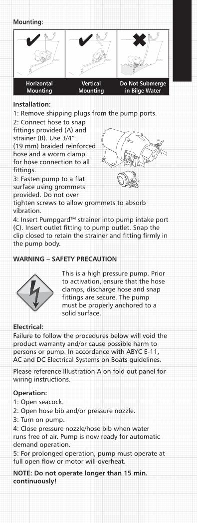
Mounting:
Horizontal Mounting
Vertical Mounting
Do Not Submerge in Bilge Water
Installation:1: Remove shipping plugs from the pump ports.2: Connect hose to snap fittings provided (A) and strainer (B). Use 3/4” (19 mm) braided reinforced hose and a worm clamp for hose connection to all fittings.3: Fasten pump to a flat surface using grommets provided. Do not over tighten screws to allow grommets to absorb vibration.4: Insert PumpgardTM strainer into pump intake port (C). Insert outlet fitting to pump outlet. Snap the clip closed to retain the strainer and fitting firmly in the pump body.
WARNING – SAFETY PRECAUTION
This is a high pressure pump. Prior to activation, ensure that the hose clamps, discharge hose and snap fittings are secure. The pump must be properly anchored to a solid surface.
Electrical:Failure to follow the procedures below will void the product warranty and/or cause possible harm to persons or pump. In accordance with ABYC E-11, AC and DC Electrical Systems on Boats guidelines.
Please reference Illustration A on fold out panel for wiring instructions.
Operation:1: Open seacock.2: Open hose bib and/or pressure nozzle.3: Turn on pump.4: Close pressure nozzle/hose bib when water runs free of air. Pump is now ready for automatic demand operation.5: For prolonged operation, pump must operate at full open flow or motor will overheat.
NOTE: Do not operate longer than 15 min. continuously!
(A)
(B)
(C)
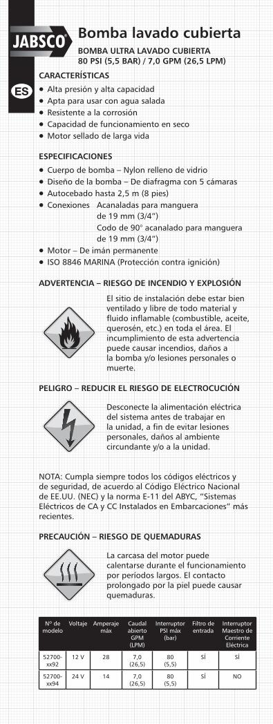
Bomba lavado cubiertaBOMBA ULTRA LAVADO CUBIERTA80 PSI (5,5 BAR) / 7,0 GPM (26,5 LPM)
CARACTERÍSTICAS
l Alta presión y alta capacidadl Apta para usar con agua saladal Resistente a la corrosión l Capacidad de funcionamiento en secol Motor sellado de larga vida
ESPECIFICACIONES
l Cuerpo de bomba – Nylon relleno de vidriol Diseño de la bomba – De diafragma con 5 cámarasl Autocebado hasta 2,5 m (8 pies) l Conexiones Acanaladas para manguera
de 19 mm (3/4”) Codo de 90° acanalado para manguera
de 19 mm (3/4”)l Motor – De imán permanentel ISO 8846 MARINA (Protección contra ignición)
ADVERTENCIA – RIESGO DE INCENDIO Y EXPLOSIÓN
El sitio de instalación debe estar bien ventilado y libre de todo material y fluido inflamable (combustible, aceite, querosén, etc.) en toda el área. El incumplimiento de esta advertencia puede causar incendios, daños a la bomba y/o lesiones personales o muerte.
PELIGRO – REDUCIR EL RIESGO DE ELECTROCUCIÓN
Desconecte la alimentación eléctrica del sistema antes de trabajar en la unidad, a fin de evitar lesiones personales, daños al ambiente circundante y/o a la unidad.
NOTA: Cumpla siempre todos los códigos eléctricos y de seguridad, de acuerdo al Código Eléctrico Nacional de EE.UU. (NEC) y la norma E-11 del ABYC, “Sistemas Eléctricos de CA y CC Instalados en Embarcaciones” más recientes.
PRECAUCIÓN – RIESGO DE QUEMADURAS
La carcasa del motor puede calentarse durante el funcionamiento por períodos largos. El contacto prolongado por la piel puede causar quemaduras.
Nº de modelo
Voltaje Amperaje máx
Caudal abiertoGPM (LPM)
InterruptorPSI máx
(bar)
Filtro de entrada
Interruptor Maestro de Corriente Eléctrica
52700-xx92
12 V 28 7,0 (26,5)
80 (5,5)
SÍ SÍ
52700-xx94
24 V 14 7,0 (26,5)
80 (5,5)
SÍ NO

Washdown PumpULTRA WASHDOWN PUMP80 PSI (5.5 BAR) / 7.0 GPM (26.5 LPM)
FEATURESl High Pressure / High capacityl Suitable for Use in Salt Waterl Corrosion Resistant l Dry Running Capabilityl Long Life Sealed Motor
SPECIFICATIONSl Pump – Glass Filled Nylonl Pump Design – 5 Chamber Diaphragml Suction Lift – Self Priming to 8 ft. (2.5 m) l Ports 3/4” (19 mm) Hose Barb 3/4” (19 mm) Hose Barb 90° elbowl Motor – Permanent Magnetl ISO 8846 MARINE (Ignition Protection)
WARNING – FIRE AND EXPLOSION HAZARD
Installation site must be well vented and free of all flammable materials and fluids (fuel, oil, kerosene, etc) from area. Failure to comply may result in fire, damage to the pump and /or personal injury or death.
DANGER – REDUCE THE RISK OF ELECTRIC SHOCK
Disconnect power from the system before working on the unit to avoid personal injury, damage to the surrounding environment and/or damage to the unit.
NOTE: Always follow all electrical and safety codes, in accordance with the most recent National Electrical Code (NEC), ABYC E-11, AC and DC Electrical Systems on Boats.
CAUTION – BURN HAZARD
Motor case could get hot during extended operation. Prolonged contact with skin may cause a burn.
Model No
Voltage Max Amp Draw
Open Flow GPM (LPM)
Switch Max PSI
(bar)
Inlet Strainer
Circuit Breaker
52700-xx92
12v 28 7.0 (26.5)
80 (5.5)
YES YES
52700-xx94
24v 14 7.0 (26.5)
80 (5.5)
YES NO
Montaje:
Montaje horizontal
Montaje vertical
No sumergir en agua de sentina
Instalación:1: Retire los tapones de transporte de las conexiones de la bomba.2: Conecte la manguera a las conexiones a presión provistas (A) y al filtro (B). Use una manguera con trenzado de refuerzo de 19 mm (3/4”) y una abrazadera tipo sinfín para todas las conexiones de la misma.3: Fije la bomba a una superficie plana usando las arandelas de goma provistas. No apriete los tornillos en exceso para permitir que las arandelas absorban las vibraciones.4: Inserte el filtro Pumpgard™ en la conexión de entrada de la bomba (C). Inserte la conexión de salida en la salida de la bomba. Cierre la grapa a presión para retener el filtro y la conexión firmemente en el cuerpo de la bomba.
ADVERTENCIA – PRECAUCIÓN DE SEGURIDAD
Ésta es una bomba de alta presión. Antes de activarla, asegúrese de que las abrazaderas de las mangueras, la manguera de descarga y los accesorios de conexión a presión estén firmemente sujetos. La bomba debe estar adecuadamente anclada a una superficie sólida.
Sistemas eléctricos:El incumplimiento de los procedimientos que se indican a continuación invalidará la garantía del producto y/o causará posibles daños a las personas o a la bomba. De acuerdo a las pautas de la norma E-11 del ABYC, “Sistemas Eléctricos de CA y CC Instalados en Embarcaciones”.
Haga referencia a la ilustración A del panel desplegable para obtener las instrucciones de cableado.
Operación:1: Abra la válvula de entrada de agua.2: Abra la boquilla de salida.3: Encienda la bomba.4: Cierre la boquilla de salida cuando el agua corra libre de aire. La bomba queda lista ahora para la operación automática a demanda.5: Para operación prolongada, la bomba debe funcionar a caudal totalmente abierto, puesto que de lo contrario el motor se recalentará.
NOTA: ¡No haga funcionar la bomba continuamente más de 15 minutos!
Red (+)
+
12V DC Battery
7 Inches Max
Main
35 AMPMain Breaker
Ring Terminals 5/16" Eye
Butt Splice
Com Bus
BatterySwitch
–
+ –
Black (–)
PanelSwitch
HelmConsole
35 AMPMain Breaker
PN#91006464A
Ring Terminals 5/16" EyeTT
Butt Splice
Com Bus
Ring Terminals 5/16" EyeTT
Butt Splice
Com Bus
Linea rossa di alimentazione (+) A
+
Batteria a 12V CC
Massimo 17 cm
Alimentazione principale
MRCB 35A
Ring Terminals 5/16" EyeTT
Butt Splice
Com Bus
Interruttoredella batteria
–
+ –
Nero (–) B
Interruttore disgiuntore di diramazione
Interruttore del pannello
della Console al timone
1 Ferramenta inclusa
2 Ferramenta venduta a parte
Sezione di ritorno
Conduttore (+)Linea (+)
2
2
2
1
1 1
1
1Giunzione a coprigiunto
Com Bus
Ring Terminals 5/16" EyeTT
Butt Splice
Com Bus
Röd elledning (+) A
+
12 V likströmsbatteri
7 tum max(20 cm max)
Central
MRCB 35A
Ring Terminals 5/16" EyeTT
Butt Splice
Com Bus
Huvudbrytare
–
+ –
Svart elledning (–) B
Individuellsäkring
Strömbrytare på förarpanel
1 Levereras med pump
2 Levereras inte med pump
Ledning (+)Ledning (+)
2
2
2
1
1 1
1
1Skarvhylsa
Skarvhylsa
Línea de alimentación roja (+) A
+
Batería de 12 V CC
178 mm máx
Interruptor principal del suministro eléctrico
MRCB 35A
Ring Terminals 5/16" EyeTT
Butt Splice
Com Bus
Interruptor de batería
–
+ –
Rama de retorno
Interruptor Maestro
de Corriente Eléctrica
Interruptor del tablero
de la consola del timón
1 Elementos incluidos
2 Elementos vendidos por separado
negra (–) B
Conexión de alimentación(+)Línea (+)
2
2
2
1
1 1
1
1Empalme a tope
Barra colectora común
(A)
(B)
(C)

Installation Guide
Guide d’installation
Einbauanleitung
Guida all’installazione
Installatiegids
Installationsmanual
Guía de instalación
52700U.S.A +1 978 281 0440UNITED KINGDOM +44 (0) 1992 450 145JAPAN +81 (0) 45 475 8906GERMANY +49 (0) 40 53 53 73 0ITALY +39 039 6852323
© Copyright 2007 ITT Corporation 950-0526 REV A 2/08
Discover Jabsco at www.jabsco.com
The products described herein are subject to the Jabsco one year limited warranty, which is available for your inspection upon request.
Les produits décrits ci-dessous bénéficient de la garantie limitée d’un an de Jabsco, que vous pouvez consulter sur simple demande.
Die nachstehend beschriebenen Produkte unterliegen einer einjährigen Gewährleistung. Die Gewährleistungsbedingungen können bei Jabsco angefordert werden.
I prodotti qui descritti sono coperti dalla garanzia Jabsco limitata di un anno, disponibile per la visione su richiesta.
De hierin beschreven producten worden aangeboden met de beperkte Jabsco garantie van één jaar. Deze is op aanvraag verkrijgbaar ter inzage.
För produkterna som beskrivs nedan utfärdar Jabsco ett års begränsad garanti, som vi kan skicka till dig på begäran.
Los productos descritos en este folleto están respaldados por la garantía limitada de Jabsco por un año, que está disponible para su lectura a pedido.
5.366.11
3.45
5.20
4.76
6.25
10.15
1.97
5.66
2.70(15.52)
(13.61)
(8.26)
(13.20)
(12.09)
(8.67)
(25.78)
(5.00)
(6.86)
(14.38)
DIMENSIONAL DRAWING
EXPLODED VIEW
ABYC WIRING CHART
Key Description 52700 - 0092 52700 - 0094 Key Description 52700 - 0092 52700 - 0094
1 Pressure Switch 18753 - 5019 18753 - 5019 5 Motor With Baseplate 18753 - 5022 18753 - 5026
2 Pump Head Kit 18753 - 5009 18753 - 5009 6 Clips 18753 - 5021 18753 - 5021
3 Check Valve Assembly 18753 - 5006 18753 - 5006 7 Cover and Seal Kit 18753 - 5030 18753 - 5030
4 Lower Housing Assembly
18753 - 5038 18753 - 5038 8 1” HB Snap Fittings (1 Pair)
30657 - 5031 30657 - 5031
10 15 20 25 30 40 50 60 70 80 90 100 110 120 130 140 150 160 170
TOTAL CURRENT ON CIRCUIT IN
AMPS 12 Volts - 3% Drop Wire Sizes (guage) – Based on Minimum CM Area
5 18 16 14 12 12 10 10 10 8 8 8 6 6 6 6 6 6 6 6
10 14 12 10 10 10 8 6 6 6 6 4 4 4 4 2 2 2 2 2
15 12 10 10 8 8 6 6 6 4 4 2 2 2 2 2 1 1 1 1
20 10 10 8 6 6 6 4 4 2 2 2 2 1 1 1 0 0 0 2/0
25 10 8 6 6 6 4 4 2 2 2 1 1 0 0 0 2/0 2/0 2/0 3/0
30 10 8 6 6 4 4 2 2 1 1 0 0 0 2/0 2/0 3/0 3/0 3/0 3/0
24 Volts - 3% Drop Wire Sizes (guage) – Based on Minimum CM Area
5 18 18 18 16 16 14 12 12 12 10 10 10 10 10 8 8 8 8 8
10 18 16 14 12 12 10 10 10 8 8 8 6 6 6 6 6 6 6 6
15 16 14 12 12 10 10 8 8 6 6 6 6 6 4 4 4 4 4 2
20 14 12 10 10 10 8 6 6 6 6 4 4 4 4 2 2 2 2 2
25 12 12 10 10 8 6 6 6 4 4 4 4 2 2 2 2 2 2 1
30 12 10 10 8 8 6 6 4 4 4 2 2 2 2 2 1 1 1 1
Length of Conductor from Source of Current to Device and Back to Source – Feet

Washdown PumpULTRA WASHDOWN PUMP80 PSI (5.5 BAR) / 7.0 GPM (26.5 LPM)
FEATURESl High Pressure / High capacityl Suitable for Use in Salt Waterl Corrosion Resistant l Dry Running Capabilityl Long Life Sealed Motor
SPECIFICATIONSl Pump – Glass Filled Nylonl Pump Design – 5 Chamber Diaphragml Suction Lift – Self Priming to 8 ft. (2.5 m) l Ports 3/4” (19 mm) Hose Barb 3/4” (19 mm) Hose Barb 90° elbowl Motor – Permanent Magnetl ISO 8846 MARINE (Ignition Protection)
WARNING – FIRE AND EXPLOSION HAZARD
Installation site must be well vented and free of all flammable materials and fluids (fuel, oil, kerosene, etc) from area. Failure to comply may result in fire, damage to the pump and /or personal injury or death.
DANGER – REDUCE THE RISK OF ELECTRIC SHOCK
Disconnect power from the system before working on the unit to avoid personal injury, damage to the surrounding environment and/or damage to the unit.
NOTE: Always follow all electrical and safety codes, in accordance with the most recent National Electrical Code (NEC), ABYC E-11, AC and DC Electrical Systems on Boats.
CAUTION – BURN HAZARD
Motor case could get hot during extended operation. Prolonged contact with skin may cause a burn.
Model No
Voltage Max Amp Draw
Open Flow GPM (LPM)
Switch Max PSI
(bar)
Inlet Strainer
Circuit Breaker
52700-xx92
12v 28 7.0 (26.5)
80 (5.5)
YES YES
52700-xx94
24v 14 7.0 (26.5)
80 (5.5)
YES NO
Montaje:
Montaje horizontal
Montaje vertical
No sumergir en agua de sentina
Instalación:1: Retire los tapones de transporte de las conexiones de la bomba.2: Conecte la manguera a las conexiones a presión provistas (A) y al filtro (B). Use una manguera con trenzado de refuerzo de 19 mm (3/4”) y una abrazadera tipo sinfín para todas las conexiones de la misma.3: Fije la bomba a una superficie plana usando las arandelas de goma provistas. No apriete los tornillos en exceso para permitir que las arandelas absorban las vibraciones.4: Inserte el filtro Pumpgard™ en la conexión de entrada de la bomba (C). Inserte la conexión de salida en la salida de la bomba. Cierre la grapa a presión para retener el filtro y la conexión firmemente en el cuerpo de la bomba.
ADVERTENCIA – PRECAUCIÓN DE SEGURIDAD
Ésta es una bomba de alta presión. Antes de activarla, asegúrese de que las abrazaderas de las mangueras, la manguera de descarga y los accesorios de conexión a presión estén firmemente sujetos. La bomba debe estar adecuadamente anclada a una superficie sólida.
Sistemas eléctricos:El incumplimiento de los procedimientos que se indican a continuación invalidará la garantía del producto y/o causará posibles daños a las personas o a la bomba. De acuerdo a las pautas de la norma E-11 del ABYC, “Sistemas Eléctricos de CA y CC Instalados en Embarcaciones”.
Haga referencia a la ilustración A del panel desplegable para obtener las instrucciones de cableado.
Operación:1: Abra la válvula de entrada de agua.2: Abra la boquilla de salida.3: Encienda la bomba.4: Cierre la boquilla de salida cuando el agua corra libre de aire. La bomba queda lista ahora para la operación automática a demanda.5: Para operación prolongada, la bomba debe funcionar a caudal totalmente abierto, puesto que de lo contrario el motor se recalentará.
NOTA: ¡No haga funcionar la bomba continuamente más de 15 minutos!
Red (+)
+
12V DC Battery
7 Inches Max
Main
35 AMPMain Breaker
Ring Terminals 5/16" Eye
Butt Splice
Com Bus
BatterySwitch
–
+ –
Black (–)
PanelSwitch
HelmConsole
35 AMPMain Breaker
PN#91006464A
Ring Terminals 5/16" EyeTT
Butt Splice
Com Bus
Ring Terminals 5/16" EyeTT
Butt Splice
Com Bus
Linea rossa di alimentazione (+) A
+
Batteria a 12V CC
Massimo 17 cm
Alimentazione principale
MRCB 35A
Ring Terminals 5/16" EyeTT
Butt Splice
Com Bus
Interruttoredella batteria
–
+ –
Nero (–) B
Interruttore disgiuntore di diramazione
Interruttore del pannello
della Console al timone
1 Ferramenta inclusa
2 Ferramenta venduta a parte
Sezione di ritorno
Conduttore (+)Linea (+)
2
2
2
1
1 1
1
1Giunzione a coprigiunto
Com Bus
Ring Terminals 5/16" EyeTT
Butt Splice
Com Bus
Röd elledning (+) A
+
12 V likströmsbatteri
7 tum max(20 cm max)
Central
MRCB 35A
Ring Terminals 5/16" EyeTT
Butt Splice
Com Bus
Huvudbrytare
–
+ –
Svart elledning (–) B
Individuellsäkring
Strömbrytare på förarpanel
1 Levereras med pump
2 Levereras inte med pump
Ledning (+)Ledning (+)
2
2
2
1
1 1
1
1Skarvhylsa
Skarvhylsa
Línea de alimentación roja (+) A
+
Batería de 12 V CC
178 mm máx
Interruptor principal del suministro eléctrico
MRCB 35A
Ring Terminals 5/16" EyeTT
Butt Splice
Com Bus
Interruptor de batería
–
+ –
Rama de retorno
Interruptor Maestro
de Corriente Eléctrica
Interruptor del tablero
de la consola del timón
1 Elementos incluidos
2 Elementos vendidos por separado
negra (–) B
Conexión de alimentación(+)Línea (+)
2
2
2
1
1 1
1
1Empalme a tope
Barra colectora común
(A)
(B)
(C)

Installation Guide
Guide d’installation
Einbauanleitung
Guida all’installazione
Installatiegids
Installationsmanual
Guía de instalación
52700U.S.A +1 978 281 0440UNITED KINGDOM +44 (0) 1992 450 145JAPAN +81 (0) 45 475 8906GERMANY +49 (0) 40 53 53 73 0ITALY +39 039 6852323
© Copyright 2007 ITT Corporation 43000-1831 07/08
Discover Jabsco at www.jabsco.com
The products described herein are subject to the Jabsco one year limited warranty, which is available for your inspection upon request.
Les produits décrits ci-dessous bénéficient de la garantie limitée d’un an de Jabsco, que vous pouvez consulter sur simple demande.
Die nachstehend beschriebenen Produkte unterliegen einer einjährigen Gewährleistung. Die Gewährleistungsbedingungen können bei Jabsco angefordert werden.
I prodotti qui descritti sono coperti dalla garanzia Jabsco limitata di un anno, disponibile per la visione su richiesta.
De hierin beschreven producten worden aangeboden met de beperkte Jabsco garantie van één jaar. Deze is op aanvraag verkrijgbaar ter inzage.
För produkterna som beskrivs nedan utfärdar Jabsco ett års begränsad garanti, som vi kan skicka till dig på begäran.
Los productos descritos en este folleto están respaldados por la garantía limitada de Jabsco por un año, que está disponible para su lectura a pedido.
5.366.11
3.45
5.20
4.76
6.25
10.15
1.97
5.66
2.70(15.52)
(13.61)
(8.26)
(13.20)
(12.09)
(8.67)
(25.78)
(5.00)
(6.86)
(14.38)
DIMENSIONAL DRAWING
EXPLODED VIEW
ABYC WIRING CHART
Key Description 52700 - 0092 52700 - 0094 Key Description 52700 - 0092 52700 - 0094
1 Pressure Switch 18753 - 5019 18753 - 5019 5 Motor With Baseplate 18753 - 5022 18753 - 5026
2 Pump Head Kit 18753 - 5009 18753 - 5009 6 Clips 18753 - 5021 18753 - 5021
3 Check Valve Assembly 18753 - 5006 18753 - 5006 7 Cover and Seal Kit 18753 - 5030 18753 - 5030
4 Lower Housing Assembly
18753 - 5038 18753 - 5038 8 1” HB Snap Fittings (1 Pair)
30657 - 5031 30657 - 5031
10 15 20 25 30 40 50 60 70 80 90 100 110 120 130 140 150 160 170
TOTAL CURRENT ON CIRCUIT IN
AMPS 12 Volts - 3% Drop Wire Sizes (guage) – Based on Minimum CM Area
5 18 16 14 12 12 10 10 10 8 8 8 6 6 6 6 6 6 6 6
10 14 12 10 10 10 8 6 6 6 6 4 4 4 4 2 2 2 2 2
15 12 10 10 8 8 6 6 6 4 4 2 2 2 2 2 1 1 1 1
20 10 10 8 6 6 6 4 4 2 2 2 2 1 1 1 0 0 0 2/0
25 10 8 6 6 6 4 4 2 2 2 1 1 0 0 0 2/0 2/0 2/0 3/0
30 10 8 6 6 4 4 2 2 1 1 0 0 0 2/0 2/0 3/0 3/0 3/0 3/0
24 Volts - 3% Drop Wire Sizes (guage) – Based on Minimum CM Area
5 18 18 18 16 16 14 12 12 12 10 10 10 10 10 8 8 8 8 8
10 18 16 14 12 12 10 10 10 8 8 8 6 6 6 6 6 6 6 6
15 16 14 12 12 10 10 8 8 6 6 6 6 6 4 4 4 4 4 2
20 14 12 10 10 10 8 6 6 6 6 4 4 4 4 2 2 2 2 2
25 12 12 10 10 8 6 6 6 4 4 4 4 2 2 2 2 2 2 1
30 12 10 10 8 8 6 6 4 4 4 2 2 2 2 2 1 1 1 1
Length of Conductor from Source of Current to Device and Back to Source – Feet
chrissico
Underline