UNIVERSIDAD TÉCNICA DEL NORTE FACULTAD DE …repositorio.utn.edu.ec/bitstream/123456789/4522/2/04...
27
UNIVERSIDAD TÉCNICA DEL NORTE FACULTAD DE INGENIERÍA EN CIENCIAS APLICADAS CARRERA DE INGENIERÍA EN MECATRÓNICA “DISEÑO E IMPLEMENTACIÓN DE UNA MÁQUINA PARA EL CORTE DE BARRAS ENERGÉTICAS DE GRANOLA PARA LA EMPRESA INDUSTRIAL PRODUCTOS EL CHINITO S.C.C”. INFORME TÉCNICO AUTOR: William Stalin Verdugo Reinoso DIRECTOR: Ing. Fernando Valencia Ibarra – Ecuador 2015
Transcript of UNIVERSIDAD TÉCNICA DEL NORTE FACULTAD DE …repositorio.utn.edu.ec/bitstream/123456789/4522/2/04...

UNIVERSIDAD TÉCNICA DEL NORTE
FACULTAD DE INGENIERÍA EN CIENCIAS APLICADAS
CARRERA DE INGENIERÍA EN MECATRÓNICA
“DISEÑO E IMPLEMENTACIÓN DE UNA MÁQUINA PARA EL CORTE DE
BARRAS ENERGÉTICAS DE GRANOLA PARA LA EMPRESA INDUSTRIAL
PRODUCTOS EL CHINITO S.C.C”.
INFORME TÉCNICO
AUTOR:
William Stalin Verdugo Reinoso
DIRECTOR:
Ing. Fernando Valencia
Ibarra – Ecuador
2015

“DISEÑO E IMPLEMENTACIÓN DE UNA MÁQUINA PARA EL CORTE DE
BARRAS ENERGÉTICAS DE GRANOLA PARA LA EMPRESA INDUSTRIAL
PRODUCTOS EL CHINITO S.C.C”.
William Stalin Verdugo Reinoso
Carrera de Ingeniería en Mecatrónica, Universidad Técnica del Norte Ibarra, Ecuador
Resumen.
El desarrollo de este proyecto, se crea en base a
la necesidad de mejorar de manera significativa la
eficiencia en el corte de barras energéticas de
granola en una forma rápida y precisa; para el
proceso de corte la máquina previamente ya
realiza el amasado y laminado de la masa; el
sistema a desarrollarse estará constituido de la
siguiente manera: el corte longitudinal de granola
será realizado mediante un rodillo el cual posee
anillos que serán los encargados de dar el ancho
de las barras energéticas de granola, la distancia
entre anillos será de 3 cm se tendrá 16
separaciones para obtener 15 barras por corte, el
movimiento del rodillo se lo realizara mediando un
motorreductor y estará controlado mediante un
variador de frecuencia.
El corte vertical se lo realizara mediante una
guillotina esta constara de un pistón neumático,
una electroválvula, un sensor, un encoder y un
PLC, el encoder se encuentra acoplado al eje de la
banda, este proporciona la medida de las barras,
las cuales serán de 10 cm por cada corte.
La máquina realiza 70 cortes por minuto logrando
así satisfacer la demanda del mercado.
1. INTRODUCCIÓN
La empresa “INDUSTRIAL PRODUCTOS EL
CHINITO S.C.C.”” actualmente se dedica a la
elaboración de barras energéticas de granola, todo
este proceso se lo realiza manualmente
impidiendo que el producto final pueda entrar en
competencia en el mercado, ya que su precio es
elevado. La etapa de cortado es una de las más
importantes del proceso ya que la elaboración de
granola en forma manual produce 30 barras en 4
minutos, es decir, produciría 450 barras en una
hora no satisfaciendo así la cantidad de productos
terminados puesto que la empresa para poder
cubrir su demanda de producto diario necesita
producir 70 barras por minuto.
Al implementar, una máquina la cual se encargue
del proceso de corte de la granola se lograra
incrementar la producción, ya que al automatizar el
proceso de corte se reduce el tiempo del proceso y
por ende se tendrá una producción constante
disminuyendo el costo del producto final.
2. PROCESOS DE PRODUCCION DE LAS
BARRAS DE GRANOLA
Para la obtención de las diferentes barras de
granola, las cuales deben poseer las dimensiones
requeridas y de esa manera cumplir con los
requisitos de la empresa se debe seguir un
procedimiento véase en la figura. 1.

Figura 1. Flujograma del proceso de producción
2.1 ESTUDIO DE CAMPO
La empresa industrial productos el chinito S.C.C.
actualmente realiza la granola de forma artesanal,
es por eso que no se cuenta con información
detallada respecto a parámetros y medios de
cortado de la masa de granola por lo cual se
procede a realizar pruebas para así obtener datos
tanto de la velocidad lineal como la fuerza de corte
especifica de la masa.
2.1.1 VELOCIDAD LINEAL
La velocidad lineal es definida como el cociente
entre el espacio recorrido y el tiempo empleado en
ello se mide en (m/s), el valor resultante se obtiene
del promedio de varias mediciones las cuales se
las realizo en 3 periodos diferentes en un lapso de
una semana cada uno, para así considerar
parámetros de la masa en condiciones diferentes,
como se detalla (véase Tabla 1.).
Ecuación 0. Velocidad lineal
Donde:
= velocidad lineal
d = distancia
t = tiempo
Tabla 0. Medición de la velocidad lineal
Velocidad lineal (m/s)
Nº de mediciones
Valor
1 0,03145
2 0,03131
3 0,03144
4 0,03159
5 0,03135
6 0,03144
7 0,03155
8 0,03149
9 0,03144
10 0,03143
11 0,03146
12 0,03144
13 0,03149
14 0,03151
15 0,03144
16 0,03143
17 0,03124
18 0,03133
19 0,03138
20 0,03159
Se obtiene que, la velocidad lineal es de 0.03144
m/s
2.1.2 CONSTANTE DE FUERZA DE CORTE
ESPECÍFICA DE LA MASA DE GRANOLA [Ks]
La constante de fuerza de corte especifica de la
masa de granola se obtiene al realizar ensayos de
corte como se observa (véase Figura 2.), se
cuantifica mediante un dinamómetro midiendo la
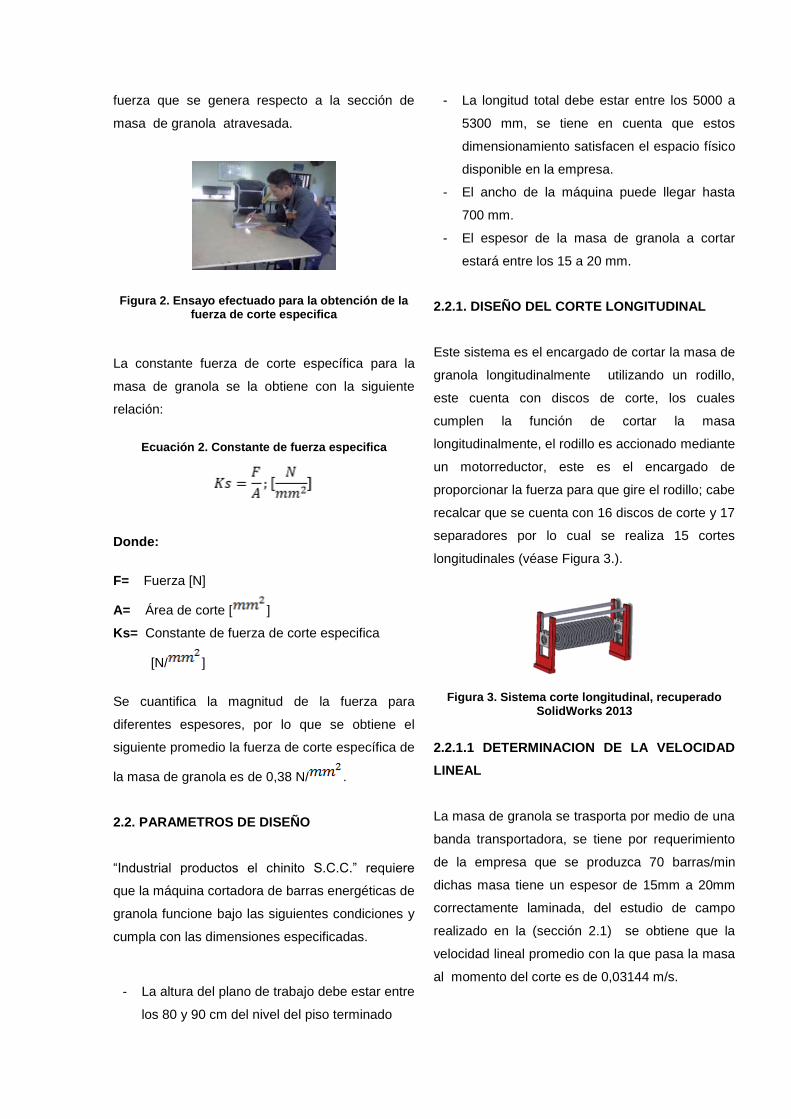
fuerza que se genera respecto a la sección de
masa de granola atravesada.
Figura 2. Ensayo efectuado para la obtención de la fuerza de corte especifica
La constante fuerza de corte específica para la
masa de granola se la obtiene con la siguiente
relación:
Ecuación 2. Constante de fuerza especifica
Donde:
F= Fuerza [N]
A= Área de corte [ ]
Ks= Constante de fuerza de corte especifica
[N/ ]
Se cuantifica la magnitud de la fuerza para
diferentes espesores, por lo que se obtiene el
siguiente promedio la fuerza de corte específica de
la masa de granola es de 0,38 N/ .
2.2. PARAMETROS DE DISEÑO
“Industrial productos el chinito S.C.C.” requiere
que la máquina cortadora de barras energéticas de
granola funcione bajo las siguientes condiciones y
cumpla con las dimensiones especificadas.
- La altura del plano de trabajo debe estar entre
los 80 y 90 cm del nivel del piso terminado
- La longitud total debe estar entre los 5000 a
5300 mm, se tiene en cuenta que estos
dimensionamiento satisfacen el espacio físico
disponible en la empresa.
- El ancho de la máquina puede llegar hasta
700 mm.
- El espesor de la masa de granola a cortar
estará entre los 15 a 20 mm.
2.2.1. DISEÑO DEL CORTE LONGITUDINAL
Este sistema es el encargado de cortar la masa de
granola longitudinalmente utilizando un rodillo,
este cuenta con discos de corte, los cuales
cumplen la función de cortar la masa
longitudinalmente, el rodillo es accionado mediante
un motorreductor, este es el encargado de
proporcionar la fuerza para que gire el rodillo; cabe
recalcar que se cuenta con 16 discos de corte y 17
separadores por lo cual se realiza 15 cortes
longitudinales (véase Figura 3.).
Figura 3. Sistema corte longitudinal, recuperado SolidWorks 2013
2.2.1.1 DETERMINACION DE LA VELOCIDAD
LINEAL
La masa de granola se trasporta por medio de una
banda transportadora, se tiene por requerimiento
de la empresa que se produzca 70 barras/min
dichas masa tiene un espesor de 15mm a 20mm
correctamente laminada, del estudio de campo
realizado en la (sección 2.1) se obtiene que la
velocidad lineal promedio con la que pasa la masa
al momento del corte es de 0,03144 m/s.

2.2.1.2 DETERMINACION DE LA VELOCIDAD
ANGULAR
La obtención de la velocidad angular se la calcula
en base a la velocidad lineal y el radio del disco de
corte, dicha velocidad angular determina la
velocidad que se necesita para cortar la masa
mediante el rodillo de corte longitudinal.
Ecuación 3. Velocidad angular
Donde:
= velocidad angular
= velocidad lineal
= radio del disco de corte
Remplazando valores tenemos:
También se representa
2.2.1.3 CÁLCULO DE LA FUERZA
Para realizar el corte de la masa de granola, se
requiere de una fuerza de corte, la misma que se
obtiene del estudio de campo realizado. De esta
manera la fuerza de corte se define como:
Ecuación 4. Fuerza de corte
Donde:
F = fuerza de corte [N]
A = (área) sección de masa [ ]
Ks = fuerza de corte especifica [N/ ]
Para obtener la sección de masa, se calcula
geométricamente mediante el siguiente análisis
(véase Figura 4.).
Figura 4. Determinación de la sección de masa
El área del sector circular se define por la siguiente
relación obtenida del libro de máquinas de trabajo
de Bartsch.
Ecuación 5. Área sección
Donde:
A¤ = área de sección
r = radio
= ángulo de corte
A = área de sección
Remplazando valores tenemos:
A¤=

A¤=3965,39
El área del triángulo que se forma en la
intersección de la cuchilla con la masa se obtiene
de la siguiente relación:
Ecuación 6. Calculo área del triangulo
Donde:
A▲= área del triangulo
b = base del triangulo
h = altura del triangulo
Remplazando valores tenemos:
A▲=
A▲= 3031,6
Por lo que, la sección de la masa se obtiene de la
diferencia entre las áreas antes calculadas.
Remplazando valores en la ecuación 4. Tenemos:
La fuerza que se encuentra es la fuerza de corte
que se genera en una cuchilla por tanto, al tener
16 cuchillas se relaciona de manera directamente
proporcional.
2.2.1.4 CÁLCULO DE LA POTENCIA
Ecuación 6. Potencia
Donde:
P = potencia [watts]; [hp]
F = fuerza total [N]
= velocidad lineal [m/s]
Remplazando valores tenemos:
2.2.1.5 DISEÑO DEL EJE DEL RODILLO DE
CORTE
En la figura se puede observar todas las fuerzas
que actúan sobre el rodillo de corte.
2.2.1.5.1 FUERZAS EN EL EJE
En la figura 5, se puede observar todas las fuerzas
que actúan sobre el rodillo de corte.
Figura 5. Rodillo cortador, recuperado de
SolidWorks 2013

Datos:
Q= 5677,4N
FA= FC = (-2315.26 j – 321.27 k) N
Al analizar las figuras 5. Con el programa MD-
SOLID se obtuvo los respectivos diagramas de
cortes y momentos, para así encontrar el valor del
momento máximo (ver Figura 6. y Figura 7.).
Figura 6. Diagrama de cortes y momentos x-y
Figura 7. Diagrama de cortes y momentos x-z
Resultados obtenidos:
2.2.1.5.1.1 DISEÑO DEL EJE DE TRASMISIÓN
Una vez analizado los diagramas de momentos
proporcionados por el programa de MD-SOLIDS
se utiliza dichos datos para realizar el diseño del
eje basándose en el libro (Robert L. Mott, 2006),
donde se utilizara las diferentes ecuaciones para
obtener los diámetros necesarios para su posterior
construcción.
Ecuación 7. Momento resultante
Ecuación 8. Diseño para ejes
Ecuación 9. Resistencia a la fatiga real
estimada
Reemplazando en la ecuación 9.
Punto A (Diámetro 1)
En este punto se encuentra la cadena la cual
produce torsión en el eje, en este punto no existe
otra fuerza por lo cual el momento flexionante en A
= 0.

Punto B (Diámetro 2)
En el punto B se encuentra un rodamiento este
posee un chaflán agudo, el cual proporciona el
tope al rodamiento a la izquierda del rodamiento
se encuentra un chaflán bien redondeado.
Los valores resultantes de dichos chaflanes se los
tomo del libro (Robert L. Mott, 2006)
Chaflán bien redondeado
Chaflán agudo
Punto C (Diámetro 4)
En el punto C se encuentra ubicados los discos de
corte por lo cual esta sección es la que se
encuentra sometida a la máxima esfuerzo y su
momento es máximo
Resultados
Punto A
Datos:
Reemplazando en la ecuación 8.
Punto B
Datos:
Chaflán bien redondeado
Chaflán agudo
Reemplazando en la ecuación 7.
Reemplazando en la ecuación 8.
Punto C
Chaflán agudo
Reemplazando en la ecuación 7.
Reemplazando en la ecuación 8.
2.2.2. DISEÑO DEL SISTEMA DE CORTE
VERTICAL

Para el desarrollo del presente sistema luego de
observar distintas técnicas y mediante pruebas
previas se pudo observar que el sistema más
idóneo que se adapta a las condiciones del corte
vertical, es el corte con cizalla accionada por
pistón neumático véase en la figura 8.
Figura 8. Sistema de corte vertical, recuperado SolidWorks 2013
2.2.2.1 DISEÑO DE LA GUILLOTINA
Esta guillotina es la encargada de cortar la masa
de granola verticalmente para dimensionar dicha
guillotina se debe tener en cuenta los siguientes
aspectos:
- El corte que va a realizar la guillotina sobre
la masa de granola previamente laminada
es de un espesor de 15mm.
- La longitud de masa de granola a cortar en
cada ciclo es de 450mm.
- La guillotina debe ser de acero inoxidable
AISI 304, este es el material que mejor se
adapta a las condiciones de corte
- Los componentes que se acoplan a la
guillotina tienen que ser de fácil
mantenimiento y remplazo.
- Fácil limpieza.
En base a los aspectos anteriormente señalados
se tiene:
Figura 9. Guillotina, recuperado SolidWorks 2013
2.2.2.2 SELECCIÓN DE UN CILINDRO
NEUMÁTICO
Para seleccionar el cilindro neumático con el que
va a funcionar nuestro sistema de corte se debe
tomar en cuenta los siguientes aspectos:
- La fuerza con la que va a trabajar el cilindro
neumático.
- La presión de trabajo que subministra el
compresor.
El sistema está soportando un peso de 7,5 kg
aproximadamente de los elementos que
conforman el sistema; se sobredimensiona dicho
peso por cuestión de seguridad en un 140% y se
supone un peso de 10 kg. La presión de trabajo
que entrega el compresor de la empresa es de
76.72 psi.
Tomando en cuenta que la fuerza necesaria será
el peso de los elementos teniendo así: F= 10kg.
Ecuación 9. Fuerza del pistón
Donde:
F = fuerza neumática necesaria
Ƥ = presión manométrica
A = área del embolo o pistón
Remplazando en la ecuación 9 se tiene:
10=(A x 5.29 bares)
A=

Para transformar de bares a se multiplica por
1.02
A=
A= 1.85
Para encontrar el diámetro del embolo se despeja
y remplaza los resultado de la ecuación 10
Ecuación 10. Área del embolo
Remplazando valores se tiene:
D=
D= = 1.53 cm
En la selección del cilindro neumático se ha
seleccionado uno de 5cm de diámetro debido a su
ergonomía de fácil adaptación al sistema de corte
vertical y una carrera de 4cm ya que es la
distancia que se necesita para producir el
movimiento de la guillotina. Las características del
cilindro neumático seleccionado se encuentran en
la tabla 2.
Tabla 2. Características técnicas del cilindro neumático
Con los datos obtenidos se procede a calcular el
área del embolo empleando la ecuación 10.
A= 0.00196
Obtenida la área del embolo se procede a calcular
la fuerza producida por el pistón empleando la
ecuación 9
F= (529000 )*(0.00196 )
F=1036,84 N
2.2.3. DISEÑO DE LA ESTRUCTURA BASE
Ahora se analiza la estructura base (véase Figura
10.), ya que es un elemento de suma importancia
en la construcción de nuestra máquina. El diseño

de la estructura está constituida mediante perfiles
en acero ASTM – 36.
Figura 10. Estructura base, recuperado SolidWorks 2013
2.2.3.1. DETERMINACION DEL MOMENTO
MÁXIMO
(Fuerza ejercida por la
guillotina)
(Fuerza ejercida por el
rodillo cortador horizontal)
(Fuerza ejercida por el
rodillo laminador)
Figura 11. Análisis de la viga MD-SOLID
Al analizar la figura11. Con el programa MD-
SOLIDS se obtuvo el diagrama de cortes y
momentos para así encontrar el valor del momento
máximo (ver figura 12.).
Figura 12. Diagrama de cortes y momentos
2.2.3.1. MÓDULO DE SECCIÓN PARA LA VIGA
Ecuación 11. Factor de seguridad
Donde:
Factor de seguridad
Resistencia de fluencia
Esfuerzo de diseño
Ecuación 12. Esfuerzo de diseño
Donde:
Módulo de sección
Momento máximo =
Esfuerzo de diseño

Reemplazando en la ecuación 11
Datos:
(Resistencia a la fluencia acero
ASTM-36)
Reemplazando en la ecuación 12
O también se expresa
2.3. DIAGRAMA DE FLUJO DEL SISTEMA DE
CONTROL
El diagrama de flujo del sistema de control véase
figura 13, permite realizar con mayor facilidad la
programación en el PLC de forma precia, dicho
proceso que demanda el corte de la granola tanto
longitudinalmente como verticalmente.
INICIO
Time = 3s
Activa banda
Cnt=3
Cnt=0
Desactivación banda
Activa electrovalvula
Sensor=1L
Time=2s
Activa banda
Time=1s
Desactiva banda
Desactiva electrovanvula
Cnt=0
SI
SI
NO
cont++
Figura 13. Diagrama de flujo
2. CONCLUSIONES
En la optimización de parámetros se
determinó, velocidad lineal 0.03144 m/s,
velocidad angular 3.75 rpm, fuerza de
corte especifica de la granola 0,38
N/ . Todos estos parámetros son
necesarios para la implementación de los
sistemas de corte.
Mediante la construcción de la máquina
cortadora de granola se optimiza el
proceso de corte de la misma, reduciendo
el tiempo y aumentando la producción
corte, el cual fluctúa entre los valores de
70 a 85 barras por minuto, dependiendo
de la demanda de producto y de la
eficiencia del personal.
Para la construcción del sistema de corte
vertical, se ha analizado tres sistemas
mediante el método ordinal corregido de
criterios ponderados, encontrando más
adecuado el sistema de corte con cizalla

accionada por pistón neumático ya que
este sistema resulta de fácil montaje tanto
de sus componentes mecánicos como los
de control. Su mantenimiento resulta
atrayente ya que todos los sistemas que
conforman este método cuentan con la
posibilidad de reparar y ser remplazados
con facilidad. Económicamente resulta
rentable ya que el sistema neumático es
relativamente barato
Para la construcción del sistema de corte
longitudinal se ha implementado un motor
trifásico de ¾ hp y esté controlado por
medio de un variador de frecuencia, el
cual regula la velocidad del motor, la
trasmisión de movimiento del motor al
rodillo se la realiza mediante cadena,
catarina con una relación de 3:1, la
frecuencia ideal para el desplazamiento
rotacional del rodillo es de 20.4 Hz.
La implementación de un controlador
lógico programable (PLC) en procesos
industriales es de gran beneficio ya que
ayuda a incrementar la producción, mejora
el rendimiento notablemente y la calidad
del producto, facilitando la utilización del
operador.
3. RECOMENDACIONES
Se recomienda para futuras mejoras de la
máquina, que es necesario de un proceso
automático de separación y arreglo en las
latas que van al horno luego de ser cortada
las barras de granola ya que esta contiene
glucosa y es necesaria una separación que
agilite el proceso.
Ya que el motor que proporciona movimiento
al rodillo de corte se encontrara protegido no
es necesario un mantenimiento continuo ni
tampoco minucioso, por lo tanto el
mantenimiento del mismo debe ser una vez
cada mil horas de trabajo, inspeccionando si
existe vibración o sobrecalentamiento estos
son indicadores previos al daño del motor.
Para el sistema de trasmisión por cadena se
recomienda realizar una lubricación manual
por goteo, utilizando una brocha o un canalón
con vertedero al menos una vez cada 8 horas
de funcionamiento, utilizar aceite SAE 30.
Una vez finalizado el proceso de corte de la
granola, se procede a lavar la maquina
inmediatamente, enfatizando su limpieza en
las partes que se encuentran en contacto
directo con la granola verificando que no
queden residuos de la misma.
Se recomienda usar la máquina, sólo para el
uso establecido, ya que si se da uso de esta
con otro fin, el fabricante no se responsabiliza
de daños ocasionados al equipo.
En caso de que se de algún imprevisto
ocasionado por el funcionamiento de los
sistemas de corte, se debe utilizar el botón de
paro de emergencia para detener el proceso
y así evitar cualquier tipo de accidente
Una vez finalizado el trabajo con la máquina
asegurarse, que se encuentren todas las
conexiones apagadas, como es la
alimentación del sistema de control y la del
sistema de potencia también revisar el
compresor, cortando la alimentación de aire.
Se recomienda a las pequeñas y medianas
empresas industriales que implementen
tecnología moderna ya que le permite cambiar
sus procesos tradicionales y de esta manera
optimizar los procesos haciéndolos más
productivos y eficientes.
Para futuras mejoras de la máquina se
recomienda realizar un proceso continuo,
donde no existan paros, los cuales aumentan

el tiempo y reducen la producción de barras de
granola.
4. REFERENCIAS BIBLIOGRÁFICAS
[1] Northon, R. L. (2004). Diseño de
Maquinaria. Cuarta Edición, Mc Graw Hill.
[2] Siemens. (2013). Siemens.
Recuperado el 21 de Marzo de 2014, de
http://cache.automation.siemens.com/dnl/z
Q/zQ1ODg5AAAA_16527461_HB/Logo_s.
pdf.
[3] Mott, R. L. (2006). Mecánica de
Fluidos. México: Sexta Edición.
[4] FESTO. (2000). Neumática Industrial .
Colombia: DIDACTIC.
[5] Solé, A. C. (2011). Neumática e
Hidráhulica. Madrid: Alfaomega. Obtenido
de 2011.
[6] Albany. (2014). Center for
Environmental Health. Obtenido de Center
for Environmental Health:
http://www.health.ny.gov/publications/7287
_es.htm
[7] Pirelli. (1961). Manual de cálculo de
cintas transportadoras. Argentina: Chubut.
[8] Albiz. (2013). Cintas transportadoras.
Bogota: Santa teresa 2011.
[9] Bartsch, W. (2008). Herramientas
máquina trabajo. Reverte.
5. BIOGRAFÍA DEL AUTOR
William Stalin Verdugo Reinoso
Nace en la ciudad de
Quito perteneciente a
Ecuador, el 12 de Marzo
de 1991. Realizó sus
estudios primarios en la
escuela Guayaquil. Sus
estudios secundarios los
curso en el Instituto
Tecnológico Superior “17 de Julio” en la
especialidad de Mecánica Automotriz. Participó en
el Concurso de robótica a nivel nacional
Interuniversitario. Actualmente es egresado de la
Universidad Técnica del Norte de Ibarra-Imbabura
en la carrera de Ingeniería en Mecatrónica en el
2015. Área de interés: Diseño mecánico,
automatización de procesos y electrónica.

TÉCNICA DEL NORTE UNIVERSITY
FACULTY OF ENGINEERING IN APPLIED SCIENCE
CAREER IN MECHATRONICS ENGINEERING
SCIENTIFIC ARTICLE
DESIGN AND IMPLEMENTATION OF A CUTTING MACHINE FOR
GRANOLA'S ENERGY BARS FOR THE INDUSTRIAL ENTERPRISE OF
PRODUCTS "EL CHINITO S.C.C"
AUTHOR:
William Stalin Verdugo Reinoso
Ibarra – Ecuador
2015

DESIGN AND IMPLEMENTATION OF A CUTTING MACHINE FOR
GRANOLA'S ENERGY BARS FOR THE INDUSTRIAL ENTERPRISE OF
PRODUCTS "EL CHINITO S.C.C"
William Stalin Verdugo Reinoso
Mechatronic Engineer Career, Técnica del Norte University Ibarra, Ecuador
Abstract.
The development of this project, is created in base
to the need to significantly improve efficiency in
cutting granola energy bars in a quickly and
accurate; for the cutting process previously the
machine already performs kneading and laminated
of the dough; the system develop shall be
constituted as follows: the longitudinal cutting of
granola will be performed by a roller which has
rings who will be responsible to give the width of
granola energy bars, the distance between rings is
3 cm will have 16 separations for get 15 bars per
cut, the movement of roller it is done by a
gearmotor and shall be controlled by a variable
frequency drive.
The vertical cut it done through a guillotine this will
consist of a pneumatic piston, a electrovalve, a
sensor , an encoder and a PLC , The encoder is
found coupled to the shaft of the band, this
provides the measure of the bars, which are 10 cm
per cut.
The machine performs 70 cuts for minute
achieving so meet market demand.
3. INTRODUCTION
THE INDUSTRIAL ENTERPRISE OF PRODUCTS
"EL CHINITO S.C.C". Today is dedicated to the
elaboration of granola energy bars, this process is
performed manually preventing that the final
product can enter on competition in the market,
since its price is high." The stage of cut is one of
the most important in the process since the
elaboration of granola manually produced 30 bars
in 4 minutes, produce 450 bars in an hour not
satisfying the quantity of finished products since
the company to meet its demand of daily intake
needs to produce 70 bars per minute.
Implementing, a machine which is responsible for
the process of cutting the granola would increase
production, to automate the cutting process is
reducing the time process and therefore will be a
constant production decreasing the cost of the final
product.
By having a machine suitable to be responsible
granola energy bars cutting, the company can
meet the demand in the market and thus increase
their profits.
4. PRODUCTION PROCESSES OF GRANOLA
BARS
To obtain different bars of granola, which must
possess the required dimensions and thus comply
with the requirements of the company must follow
a procedure see Figure 1.

Figure 1. Flowchart of the production process
2.1 FIELD STUDY
THE INDUSTRIAL ENTERPRISE OF PRODUCTS
"EL CHINITO S.C.C". is currently the granola by
hand, so that you do not have complete
information regarding parameters and cut granola
mass media by which we proceed to perform tests
for both the linear velocity data as specified by the
cutting force of the mass
2.1.1 LINEAR VELOCITY
The linear velocity is defined as the ratio between
travel and the time spent on it is measured in
(m/s), the resulting value is obtained from the
average of several measurements which I
performed at 3 different times in a span of one
week each, for thus consider parameters of mass
in different conditions, as detailed (see table 1.).
Equation 0. Linear velocity
Where:
= linear velocity
d = distance
t = time
Table 0. Measurement of linear velocity
Linear velocity (m/s)
Nº Measurements
Value
1 0,03145
2 0,03131
3 0,03144
4 0,03159
5 0,03135
6 0,03144
7 0,03155
8 0,03149
9 0,03144
10 0,03143
11 0,03146
12 0,03144
13 0,03149
14 0,03151
15 0,03144
16 0,03143
17 0,03124
18 0,03133
19 0,03138
20 0,03159
You get that, the linear velocity is 0.03144 m/s
2.1.2 CONSTANT SPECIFIC CUTTING FORCE
OF THE MASS OF GRANOLA
The constant specifies cutting force granola mass
is obtained by conducting court trials as shown
(see Figure 2.), is quantified by means of a
dynamometer measuring the force that is
generated with respect to the section of mass of
crossed granola.

Figure 2. Specifies test performed to obtain the cutting force
The constant specifies cutting force for the mass of
granola is obtained with the following relation:
Equation 2. Constant specific cutting force
Where:
F= force [N]
A= cutting area [ ]
Ks= constant specific cutting force [N/ ]
It quantifies the magnitude of force for different
thicknesses, so the following average granola
mass-specific cutting force is obtained is 0,38
N/ .
2.2. DESIGN PARAMETERS
THE INDUSTRIAL ENTERPRISE OF PRODUCTS
"EL CHINITO S.C.C", requires that energy bars
cutting machine of Granola run under the following
conditions and complies with specified dimensions.
- The height of the work surface should be
between 80 and 90 cm from the level of the
finished floor.
- The length should be between 5000 to 5300
mm, taking into account that these size
satisfy the physical space available in the
company.
- The width of the machine accessible up to
700 mm.
- The thickness of the mass of granola to be
cut will be among the 15 to 20 mm.
- Electrical input power that the company is of
type single phase 220V 60 Hz.
2.2.1. DESIGN OF THE LONGITUDINAL CUT
This system is responsible for cutting the mass of
granola lengthwise using a roller, this has cut
discs, which have the function of ripping the dough
roller is driven by a gear motor, this is responsible
for providing the force to make it turn the roller;
should be noted that you there is with 16 discs cut
and 17 separators by which is 15 longitudinal cuts
(see Figure 3.).
Figure 3. System longitudinal cut, SolidWorks 2013
2.2.1.1 DETERMINATION OF LINEAR VELOCITY
The mass of granola is transported by means of a
conveyor belt, has upon request of the company
produced 70 bars/min these mass has a thickness
of 15 mm to 20 mm properly laminated, in (section
2.1) field study Gets the average linear velocity
that passes the dough at the time of the Court is
0,03144 m/s.
2.2.1.2 DETERMINATION OF ANGULAR
VELOCITY

The obtain angular velocity was calculated on the
basis of the linear velocity and the radius of the
blade, the angular speed determines the speed
needed to cut the dough through the roller slitting.
Equation 3. Angular velocity
Where:
= angular velocity
= linear velocity
= radio of the cut-off
Replacing the values we have:
It also represents
2.2.1.3 CALCULATION OF FORCE
Make granola mass cutting, a cutting force, which
is obtained from the done field study is required. In
this way the cutting force is defined as:
Equation 4. Cutting force
Where:
F = forcé cutting [N]
A = (area) mass section [ ]
Ks= specific cutting force [N/ ]
To obtain the mass section, calculated
geometrically using the following analysis (see
Figure 4.).
Figure 4. Determination of the mass section
The area of the circular sector is defined by the
following relation obtained from the book of
Bartsch working machines.
Equation 5. Area section
Where:
A¤ = área section
r = radio
= cutting angle
Replacing the values we have:
A¤=
A¤=3965,39

The area of the triangle formed at the intersection
of the blade with the mass is obtained from the
following relationship:
Equation 6. Calculating area of the triangle
Where:
A▲= area of the triangle
b = base of the triangle
h= height of the triangle
Replacing the values we have:
A▲=
A▲= 3031,6
So, the section of the mass is obtained from the
difference between the previously calculated
areas.
Replacing values in equation 4. We have:
Force that is is cutting force generated in a blade
so having 16 blades relates directly proportionally.
2.2.1.4 POWER CALCULATION
Equation 6. Power
Where:
P = power [watts]; [hp]
F = Force [N]
= linear velocity [m/s]
Replacing the values we have:
2.2.1.5 DESIGN OF THE CUTTING ROLLER
SHAFT
In the figure you can see all forces that Act on the
Court roll.
2.2.1.5.1 THE AXIS FORCES
In the figure you can see all forces that Act on the
Court roll.
Figure 5. Roller cutter, recovered from SolidWorks 2013

Data: Q= 5677,4N
FA= FC = (-2315.26 j – 321.27 k) N
Analyzing the figures 5. MD-SOLID program was
obtained the respective diagrams of cuts and
moments, to find the value of the maximum
moment (see Figure 6. and Figure 7.).
Figure 6. Diagram of cuts and moments x -y
Figure 7. Diagram of cuts and moments x -z
Results obtained:
2.2.1.5.1.1 DESIGN OF THE TRANSMISSION
SHAFT
Analyzed once diagrams moments provided by
MD-SOLIDS program is used such data to make
the shaft design based on the book (Robert L.
Mott, 2006), where different equations used to
obtain required diameters for subsequent
construction.
Equation 7. Resulting time
Equation 8. Design for shafts
Equation 9. Fatigue resistance real estimated
Replacing in equation 9.
Point A (diameter 1)
At this point is the chain which produces torque on
the shaft, in this point there is another force which
the moment flexionante a = 0.

Point B (diameter 2)
In point B is a bearing this possesses a sharp
chamfer, which provides the stop rolling to the left
of the bearing is a well-rounded chamfer.
I take the resulting values of the chamfers is book
(Robert L. Mott, 2006)
Well-rounded chamfer
Acute chamfer
Point C (diameter 4)
Point C is located the cutting disks so this section
is the one that is subject to the maximum effort and
time is maximum
Results
Point A
Dates:
Replacing in the equation 8.
Point B
Dates:
Chamfer well rounded
Chamfer acute
Replacing in the equation 7.
Replacing in the equation 8.
Point C
Chaflán agudo
Replacing in the equation 7.
Replacing in the equation 8.

2.2.2. DESIGN OF THE VERTICAL CUT SYSTEM
The development of this system then observe
different technical and previous tests could be
observed that the most suitable system that adapts
to the conditions of vertical cut, is cut with shears
powered by pneumatic piston see Figure 8.
Figure 8. System of vertical cut, recovered SolidWorks 2013
2.2.2.1 DESIGN OF THE GUILLOTINE
This guillotine is responsible for cutting granola
mass vertically to measure such guillotine must
take into account the following aspects:
- The cut going to the guillotine on the mass of
previously laminated granola is a thickness
of 15 mm.
- The mass of granola to be cut in each cycle
is 450 mm.
- The guillotine must be of stainless steel AISI
304, this is the material that best suits the
cutting conditions
- The components that are attached to the
guillotine should be easy maintenance and
replacement.
Based on the above mentioned aspects you have:
Figure 9. Guillotine, recovered SolidWorks 2013
2.2.2.2 SELECTION OF A PNEUMATIC
CYLINDER
To select the pneumatic cylinder which will run our
court system is must take into account the
following parameters:
- The force that goes to work pneumatic
cylinder
- Working pressure which supplies
compressor
- The weight of the components that are
attached to the system
The system is under a weight of 7.5 kg
approximately of the elements that make up the
system; it exaggerates this weight by security by
140% and assumes a weight of 10 kg.
Working pressure which supplies compressor with
which the company has 120 PSI, is a 10 hp
compressor.
Below is the relevant calculations:
Equation 9 Piston force
Where:
F = pneumatic force required
Ƥ = pressure gauge (pressure given by the
compressor)
A = area of the plunger or piston
Replacing in equation 9 is:
10=(A x 5.29 bares)
A= 10/5.29 bar

To convert bars to is multiplied by 1.02
A=
A= 1.85
To find the diameter of the plunger is clear and
replaces the result from equation 10.
Equation 10. Area of the plunger
Replacing values is:
D =
D =
D = 1.53 cm
In the selection of pneumatic cylinder has been
selected one of 5cm in diameter due to its
ergonomics of easy adaptation to the system of
vertical cut and a race of 4 cm it is the distance
that is needed to produce the motion of the
guillotine. The characteristics of selected
pneumatic cylinder are found in table 2.
Table 2. Technical characteristics of pneumatic cylinder
With the data obtained proceeds to calculate the
area of the plunger using equation 10.
A= 0.00196
Obtained the area of the piston we proceed to
calculate the force produced by the piston using
equation 9
F= (529000 )*(0.00196 )
F=1036,84 N
2.2.3 DESIGN OF BASE STRUCTURE
Now analyzes the structure base (see Figure 10.),
since it is an element of utmost importance in the
construction of our machine. The design of the
structure is made up profiles in steel ASTM - 36.

Figure 10. Structure base recovered SolidWorks 2013
2.2.3.1. DETERMINATION OF THE MAXIMUM
MOMENT
(Force exerted by
the guillotine)
(Force exerted by
the horizontal
cutter roller)
(Force exerted by
the roller mill)
Figure 11. MD-SOLID beam analysis
Analyzing the figure 11. MD-SOLIDS program was
the diagram of cuts and moments to find the value
of the maximum moment (see Figure 12).
Figure 12. Diagram of cuts and moments
2.2.3.1. MODULE FOR BEAM SECTION
Equation 11. Safety factor
Where:
Safety factor
Creep resistance
Design effort
Equation 12. Module the section
Where:
Section module
Maximum moment
Design effort

Replacing in the equation 11
Replacing in the equation 12
o
2.3. CONTROL SYSTEM FLOW DIAGRAM
INICIO
Time = 3s
Activa banda
Cnt=3
Cnt=0
Desactivación banda
Activa electrovalvula
Sensor=1L
Time=2s
Activa banda
Time=1s
Desactiva banda
Desactiva electrovanvula
Cnt=0
SI
SI
NO
cont++
Figure 13. Flowchart
6. COST ANALYSIS
In the optimization of parameters was
determined, linear speed 0.03144 m/s,
angular velocity 3.75 rpm, cutting force
specifies the Granola 0.38 N/ . All these
parameters are necessary for the
implementation of court systems.
Through the construction of slicer's granola
is optimized cutting of the same process,
reducing time and increasing the production
cut, which fluctuates between the values of
70 to 85 bars per minute, depending on the
demand for product and the efficiency of the
staff.
For the construction of the vertical cut
system, it has analyzed three sets by using
the fixed ordinal method of weighted criteria,
finding most suitable cutting system with
shears powered by pneumatic piston since
this system is easy to install much of its
mechanical components such as the control.
Maintenance is attractive because all the
systems that make up this method have the
possibility of repair and be replaced with
ease. It is economically profitable since the
pneumatic system is relatively inexpensive.
For the construction of the system of slitting
¾ hp three phase motor has been
implemented and is controlled by a
frequency inverter, which regulates the
speed of the motor, transmission of the
motor movement to roll performed by string,
catarina with a ratio of 3:1, the ideal
frequency for the rotational movement of the
roller is 20.4 Hz.

Production, significantly improves the
performance and the quality of the product,
facilitating the use of the operator.
7. RECOMMENDATIONS
Is recommended for future improvements of
the machine, whereas an automatic process
of separation and arrangement in cans
ranging baked after being cut granola bars
since it contains glucose and a separation
that agilite the process is required.
Since engine that provides motion to cut roll
you'll find protected neither thorough nor
continuous maintenance is not necessary,
therefore the maintenance of the product
must be once every thousand hours of work,
checking if there is vibration or overheating
these are indicators prior to the damage of
the engine.
For chain transmission system is
recommended to perform a manual drip
lubrication, using a brush or a gutter with Weir
at least once every 8 hours of operation, use
SAE 30 oil.
Once the process of cutting of granola,
proceeds to wash the machine immediately,
emphasizing its cleaning in the parts that are
in direct contact with the granola verifying that
there are no residues of the same.
Is recommended to use the machine only for
the established, since if you use it for another
purpose, the manufacturer is not responsible
for damage to equipment.
Should be of some unexpected caused by the
operation of cutting systems, you should use
the emergency stop button to stop the
process and avoid any kind of accident
Is recommended for small and medium-sized
industrial enterprises that implement modern
technology since it allows you to change their
traditional processes in this way optimize the
processes making them more productive and
efficient.
8. For future improvements of the machine it is
recommended to perform a continuous
process, where there are no stoppages,
which increase the time and reduce the
production of granola bars. REFERENCES
[1] Northon, R. L. (2004). Diseño de
Maquinaria. Cuarta Edición, Mc Graw Hill.
[2] Siemens. (2013). Siemens.
Recuperado el 21 de Marzo de 2014, de
http://cache.automation.siemens.com/dnl/z
Q/zQ1ODg5AAAA_16527461_HB/Logo_s.
pdf.
[3] Mott, R. L. (2006). Mecánica de
Fluidos. México: Sexta Edición.
[4] FESTO. (2000). Neumática Industrial .
Colombia: DIDACTIC.
9. ABOUT AUTHOR
William Stalin Verdugo Reinoso
Born in the city of Quito
from Ecuador, on March
12 of 1991. He studied
primary school Guayaquil.
High school course in the
higher technological
Institute "17 Julio" in the
specialty of auto
mechanics. He participated in the Robotics
national inter-university competition. Currently he is
a graduate of Northern technical college in Ibarra-
Imbabura in engineering in Mechatronics in 2015.
Area of interest: mechanical design, process
automation and electronics.