


Idiomas
Páginas
Jurídico


ii
“industrialberry_datasheet” — 2014/1/22 — 20:50 — page 1 — #1 ii
ii
ii
CanBarry PI V 1.1
INDUSTRIALBERRY
www.industrialberry.com
February 2014

ii
“industrialberry_datasheet” — 2014/1/22 — 20:50 — page 2 — #2 ii
ii
ii

ii
“industrialberry_datasheet” — 2014/1/22 — 20:50 — page i — #3 ii
ii
ii
Contents
1 License 11.1 Disclaimer . . . . . . . . . . . . . . . . . . . . . . . . . . . . . . 1
2 Introduction 3
3 Hardware implementation 5
4 Software implementation 94.1 Real Time Clock . . . . . . . . . . . . . . . . . . . . . . . . . . 10
4.1.1 RTC with shell . . . . . . . . . . . . . . . . . . . . . . . 104.2 LED Control . . . . . . . . . . . . . . . . . . . . . . . . . . . . 11
5 Components list 13
Bibliography 15
i

ii
“industrialberry_datasheet” — 2014/1/22 — 20:50 — page ii — #4 ii
ii
ii

ii
“industrialberry_datasheet” — 2014/1/22 — 20:50 — page iii — #5 ii
ii
ii
List of Figures
2.1 CanBerry V1.1 on Raspberry PI . . . . . . . . . . . . . . . . . 42.2 CanBerry V1.1 . . . . . . . . . . . . . . . . . . . . . . . . . . . 4
3.1 Electric diagram of CanBus block . . . . . . . . . . . . . . . . . 63.2 Electric diagram of RTC block . . . . . . . . . . . . . . . . . . 73.3 CanBerry Connector . . . . . . . . . . . . . . . . . . . . . . . . 73.4 CAN Bus example, image from http://en.wikipedia.org/wiki/
File:CAN-Bus_Elektrische_Zweidrahtleitung . . . . . . . . 83.5 CANH Bus monitoring . . . . . . . . . . . . . . . . . . . . . . . 8
iii

ii
“industrialberry_datasheet” — 2014/1/22 — 20:50 — page iv — #6 ii
ii
ii

ii
“industrialberry_datasheet” — 2014/1/22 — 20:50 — page v — #7 ii
ii
ii
List of Tables
5.1 CanBerry Pi V 1.1 . . . . . . . . . . . . . . . . . . . . . . . . . 14
v

ii
“industrialberry_datasheet” — 2014/1/22 — 20:50 — page vi — #8 ii
ii
ii

ii
“industrialberry_datasheet” — 2014/1/22 — 20:50 — page 1 — #9 ii
ii
ii
Chapter 1
License
Open-source hardware shares much of the principles and approach of free andopen-source software. In particular, we believe that people should be ableto study our hardware to understand how it works, make changes to it, andshare those changes. To facilitate this, we release all of the original design files(Eagle CAD) for the IndustrialBerry hardware. These files are licensed undera Creative Commons Attribution Share-Alike license, which allows for bothpersonal and commercial derivative works, as long as they credit Industrial-Berry and release their designs under the same license. The IndustrialBerrysoftware/firmware is also open-source.
1.1 DisclaimerIn no event shall Industrialberry be liable to the buyer or to any third partyfor any indirect, incidental, special, consequential, punitive or exemplary dam-ages (including without limitation lost profits, lost savings, or loss of businessopportunity) arising out of or relating to any product or service provided or tobe provided by Industrialberry, or the use or inability to use the same, even ifIndustrialberry has been advised of the possibility of such damages.
1

ii
“industrialberry_datasheet” — 2014/1/22 — 20:50 — page 2 — #10 ii
ii
ii

ii
“industrialberry_datasheet” — 2014/1/22 — 20:50 — page 3 — #11 ii
ii
ii
Chapter 2
Introduction
CanBerry Pi V 1.1 is an extension board for RaspBerry Pi. It is an OpenHardware Design. It has two functionalities: a can bus module and an on-board Real Time clock powered by a 12 mm battery. In fig 2.1 is shown theBoard on Raspberry PI. The CanBus is based on MCP2515 [1] SPI controllerand the MCP2551 [2] tranceiver. All functionalities are full integrated in stan-dard linux kernel, so, they can be avaible on fly, or at last recompiling linuxkernel to add canbus functionalities. The real time clock is based on DS1307Z[3] I2C controller. It is full compatible with linux too. Using I2C Kernel mod-ule, and standard kernel functions, date and hour can be set/get by simplecommands. On the bottom side is located an on board battery to guarantee adata autonomy more than 20 years. In chapter hardware there are all informa-tions on principal components, schematics to rebuild and modify RaspBerryPI board. In chapter Software is reported how all hardware can be used: asrecompile kernel, build simple user space function to set and get I2C data, etc...In chapter application is reported a typical example of how to use the board.
3

ii
“industrialberry_datasheet” — 2014/1/22 — 20:50 — page 4 — #12 ii
ii
ii
Chapter 2 Introduction
Figure 2.1: CanBerry V1.1 on Raspberry PI
Figure 2.2: CanBerry V1.1
4
ii
“industrialberry_datasheet” — 2014/1/22 — 20:50 — page 5 — #13 ii
ii
ii
Chapter 3
Hardware implementation
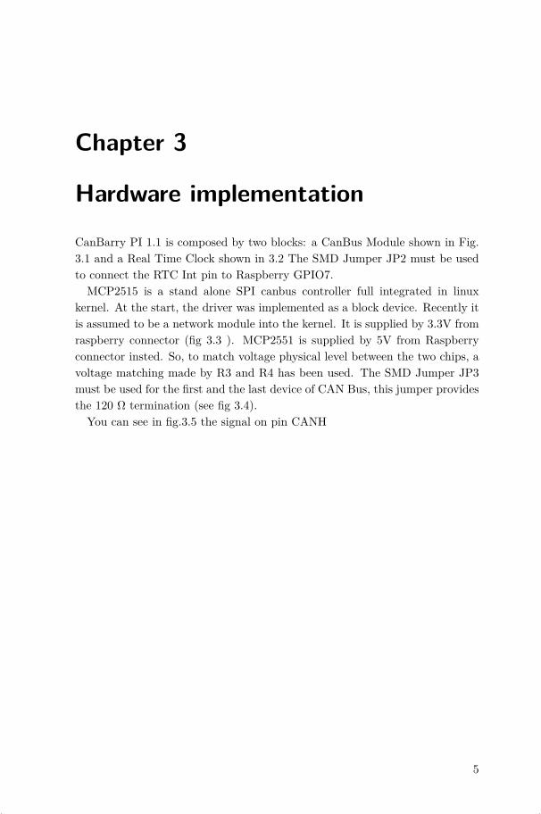
CanBarry PI 1.1 is composed by two blocks: a CanBus Module shown in Fig.3.1 and a Real Time Clock shown in 3.2 The SMD Jumper JP2 must be usedto connect the RTC Int pin to Raspberry GPIO7.MCP2515 is a stand alone SPI canbus controller full integrated in linux
kernel. At the start, the driver was implemented as a block device. Recently itis assumed to be a network module into the kernel. It is supplied by 3.3V fromraspberry connector (fig 3.3 ). MCP2551 is supplied by 5V from Raspberryconnector insted. So, to match voltage physical level between the two chips, avoltage matching made by R3 and R4 has been used. The SMD Jumper JP3must be used for the first and the last device of CAN Bus, this jumper providesthe 120 Ω termination (see fig 3.4).
You can see in fig.3.5 the signal on pin CANH
5

ii
“industrialberry_datasheet” — 2014/1/22 — 20:50 — page 6 — #14 ii
ii
ii
Chapter 3 Hardware implementation
14/0
4/20
13 1
6:50
:38
D:\R
aspb
erry
_har
dwar
e\C
AN&R
TC\C
AN&R
TC1v
0\C
AN&R
TC.s
ch (S
heet
: 1/1
)
Bat
tery
Hol
der C
R20
32
GN
DG
ND
10k
10k
100n
F
32.7
68kH
z
GN
D
V+
GN
D
GN
DV+
MC
P25
15-I/
SO
GR
B2
RS
C 6
28-3
548
120R
18k
10k 10
0nF
100n
F
22pF22pF
GN
D
GN
D
GN
DG
ND
V+
GN
D
GN
D
4k7
GN
D
4k7V+
GN
D
n.c.
n.c. GN
Dn.c.
n.c. GN
D
GN
DG
ND
500R
500R
V+
V+
V+
V+
V+
1uF
16Mhz
GN
D
1 2 3 4
JP1
R8
R11
C8
X11
X22
Q2
1 2
JP2
OSC
IO
SCO
VBAT
GN
DSD
ASC
L
INT
VDD
IC3
F
F1
F
F2
1-+3
V31
2-+5
V2
3-SD
A03
4-D
NC
4
5-SC
L05
6-G
ND
6
7-G
PIO
77
8-TX
8
9-D
NC
910
-RX
10
11-G
PIO
011
12-G
PIO
112
13-G
PIO
213
14-D
NC
14
15-G
PIO
315
16-G
PIO
416
17-D
NC
1718
-GPI
O5
18
19-S
PI-M
OSI
1920
-DN
C20
21-S
PI-M
ISO
2122
-GPI
O6
22
23-S
PI-S
CLK
2324
-SPI
-CE0
-N24
25-D
NC
2526
-SPI
-CE1
-N26
RES
ET17
CS
16
SO15
SI14
SCK
13
INT
12
RX0
BF11
RX1
BF10
TX0R
TS4
TX1R
TS5
TX2R
TS6
VDD
18
TXC
AN1
RXC
AN2
CLK
OU
T3
OSC
27
OSC
18
VSS
9
IC2
1JP32 R10
TXD
1
RXD
4
VSS
2
VDD
3C
ANH
7
CAN
L6
RS
8
VREF
5
IC1
R4
R3
C4
C2
C7C5
R7
R5
C6
R9C3
R6
LED2
R1
LED1
R2
BAT100
C1
Q1
22
11
33
SD
A
SD
A
SD
AS
CL
SC
L
SC
L
LED
1LE
D2
OU
T
OU
T
OS
CI
OSCI
OS
CO
OSCO
PI_
5V
PI_
5VP
I_S
PI_
CE
0
PI_
SP
I_C
E0
PI_
SP
I_S
CLK
PI_
SP
I_S
CLK
PI_
SP
I_M
ISO
PI_
SP
I_M
ISO
PI_
SP
I_M
OS
I
PI_
SP
I_M
OS
I
PI_
GP
IO_P
IN22
PI_
GP
IO_P
IN22
MCP2551
Dra
wn
By:
Title
:Ve
rsio
n:
JP4
Figure 3.1: Electric diagram of CanBus block
6

ii
“industrialberry_datasheet” — 2014/1/22 — 20:50 — page 7 — #15 ii
ii
ii
Figure 3.2: Electric diagram of RTC block
14/04/2013 16:51:00 D:\Raspberry_hardware\CAN&RTC\CAN&RTC1v0\CAN&RTC.sch (Sheet: 1/1)
Battery Holder CR2032
GNDGND
10k
10k
100nF
32.768kHz
GND
V+
GND
GND
V+
MCP2515-I/SOGRB2 RSC 628-3548
120R
18k
10k
100nF
100nF
22pF
22pF
GND
GND
GNDGND
V+
GND
GND
4k7GND
4k7
V+
GND
n.c.
n.c.
GND
n.c.
n.c.
GND
GND GND
500R
500R
V+
V+V
+
V+
V+
1uF
16M
hz
GND
1234
JP1
R8
R11
C8
X1 1X22
Q2
12
JP2OSCIOSCO
VBATGND SDA
SCL
INTVDD
IC3
F
F1
F
F2
1-+3V31 2-+5V 2
3-SDA03 4-DNC 4
5-SCL05 6-GND 6
7-GPIO77 8-TX 8
9-DNC9 10-RX 10
11-GPIO011 12-GPIO1 12
13-GPIO213 14-DNC 14
15-GPIO315 16-GPIO4 16
17-DNC17 18-GPIO5 18
19-SPI-MOSI19 20-DNC 20
21-SPI-MISO21 22-GPIO6 22
23-SPI-SCLK23 24-SPI-CE0-N 24
25-DNC25 26-SPI-CE1-N 26
RESET17
CS16
SO15
SI14
SCK13
INT12
RX0BF11
RX1BF10
TX0RTS4
TX1RTS5
TX2RTS6
VDD 18
TXCAN 1
RXCAN 2
CLKOUT 3
OSC2 7
OSC1 8
VSS 9
IC2
1JP
32
R10
TXD1
RXD4
VSS2
VDD3 CANH 7
CANL 6
RS 8
VREF 5
IC1
R4
R3
C4
C2
C7
C5
R7
R5
C6
R9
C3
R6
LED
2
R1
LED
1
R2
BAT
100
C1
Q1
22
11
33
SDA
SDA
SDASCL
SCL
SCL
LED1 LED2
OUT
OUT
OSCI
OS
CI
OSCOOS
CO
PI_5V
PI_5VPI_SPI_CE0
PI_SPI_CE0PI_SPI_SCLK
PI_SPI_SCLK
PI_SPI_MISO
PI_SPI_MISO
PI_SPI_MOSI
PI_SPI_MOSI
PI_GPIO_PIN22
PI_GPIO_PIN22
MC
P25
51
Drawn By:
Title:Version:
JP4
Figure 3.3: CanBerry Connector
7

ii
“industrialberry_datasheet” — 2014/1/22 — 20:50 — page 8 — #16 ii
ii
ii
Chapter 3 Hardware implementation
Figure 3.4: CAN Bus example, image from http://en.wikipedia.org/wiki/File:CAN-Bus_Elektrische_Zweidrahtleitung
Figure 3.5: CANH Bus monitoring
8
ii
“industrialberry_datasheet” — 2014/1/22 — 20:50 — page 9 — #17 ii
ii
ii
Chapter 4
Software implementation
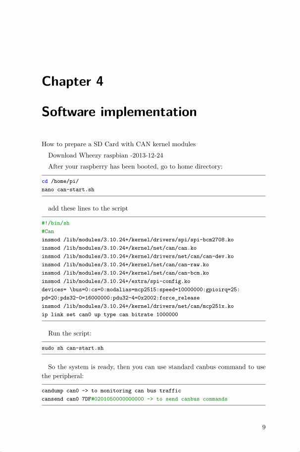
How to prepare a SD Card with CAN kernel modulesDownload Wheezy raspbian -2013-12-24After your raspberry has been booted, go to home directory:
cd /home/pi/nano can-start.sh
add these lines to the script
#!/bin/sh#Caninsmod /lib/modules/3.10.24+/kernel/drivers/spi/spi-bcm2708.koinsmod /lib/modules/3.10.24+/kernel/net/can/can.koinsmod /lib/modules/3.10.24+/kernel/drivers/net/can/can-dev.koinsmod /lib/modules/3.10.24+/kernel/net/can/can-raw.koinsmod /lib/modules/3.10.24+/kernel/net/can/can-bcm.koinsmod /lib/modules/3.10.24+/extra/spi-config.kodevices= \bus=0:cs=0:modalias=mcp2515:speed=10000000:gpioirq=25:pd=20:pds32-0=16000000:pdu32-4=0x2002:force_releaseinsmod /lib/modules/3.10.24+/kernel/drivers/net/can/mcp251x.koip link set can0 up type can bitrate 1000000
Run the script:
sudo sh can-start.sh
So the system is ready, then you can use standard canbus command to usethe peripheral:
candump can0 -> to monitoring can bus trafficcansend can0 7DF#0201050000000000 -> to send canbus commands
9

ii
“industrialberry_datasheet” — 2014/1/22 — 20:50 — page 10 — #18 ii
ii
ii
Chapter 4 Software implementation
4.1 Real Time Clock
It is possible use the RTC IC with the terminal or with a compiled program.The DS1307Z is a device I2C, and then we must install i2c-tool
sudo aptitude install i2c-tool
and libi2c-dev before use it.
sudo aptitude install libi2c-dev
4.1.1 RTC with shell
The following code allow the management of the RTC with the i2c-tool directlyfrom the shell. Verify the DS1307Z address 0x68 with
sudo i2cdetect -y 0
for Raspberry Rev 1 or
sudo i2cdetect -y 1
for Rev 2, because the I2C bus address changed from 0 to 1.Run the scripts as root:
modpro be rtc-ds1307
Then, run
echo ds1307 0x68 > /sys/class/i2c-adapter/i2c-0/new_device (if you havea Rev 1 Pi)
echo ds1307 0x68 > /sys/class/i2c-adapter/i2c-1/new_device (if you havea Rev 2 Pi)
Set RTC with
hwclock -w
Read RTC with
hwclock -r
10

ii
“industrialberry_datasheet” — 2014/1/22 — 20:50 — page 11 — #19 ii
ii
ii
4.2 LED Control
4.2 LED Control
Go to home directory:
cd /home/pi/nano gpio_on.sh
add these lines to the script
#!/bin/sh
# GPIO On numbers should be from this list# 0, 1, 4, 7, 8, 9, 10, 11, 14, 15, 17, 18, 21, 22, 23, 24, 25
# Set up GPIO 17 and set to outputecho "17" > /sys/class/gpio/exportecho "out" > /sys/class/gpio/gpio17/direction
# Set up GPIO 21 and set to outputecho "21" > /sys/class/gpio/exportecho "out" > /sys/class/gpio/gpio21/direction
# Write output#Led1 Onecho "1" > /sys/class/gpio/gpio17/value#Led2 Onecho "1" > /sys/class/gpio/gpio21/value
# Clean upecho "17" > /sys/class/gpio/unexportecho "21" > /sys/class/gpio/unexport
nano gpio_off.sh
add these lines to the script
#!/bin/sh
# GPIO Off numbers should be from this list# 0, 1, 4, 7, 8, 9, 10, 11, 14, 15, 17, 18, 21, 22, 23, 24, 25
# Set up GPIO 17 and set to outputecho "17" > /sys/class/gpio/exportecho "out" > /sys/class/gpio/gpio17/direction
11

ii
“industrialberry_datasheet” — 2014/1/22 — 20:50 — page 12 — #20 ii
ii
ii
Chapter 4 Software implementation
# Set up GPIO 21 and set to outputecho "21" > /sys/class/gpio/exportecho "out" > /sys/class/gpio/gpio21/direction
# Write output#Led1 Offecho "0" > /sys/class/gpio/gpio17/value#Led2 Offecho "0" > /sys/class/gpio/gpio21/value
# Clean upecho "17" > /sys/class/gpio/unexportecho "21" > /sys/class/gpio/unexport
Run the scripts as root:
sh gpio_on.shsh gpio_off.sh
12

ii
“industrialberry_datasheet” — 2014/1/22 — 20:50 — page 13 — #21 ii
ii
ii
Chapter 5
Components list
In the table 5.1 we can see the Bill of Material for the board, all the componentsare available on-line. For simplicity, every component has a DigiKey order code(www.digikey.com).
13

ii
“industrialberry_datasheet” — 2014/1/22 — 20:50 — page 14 — #22 ii
ii
ii
Chapter 5 Components list
Quantity
ValuePackage
PartsDigikey-cod
Unit
Price$
2Yellow
1206LED
1,LED2
754-1144-1-ND
0,210,42
1120
Ω0603
R10
RMCF0603JT
120RCT-N
D0,02
0,022
499Ω
0603R1,R
2RMCF0603FT
499RCT-N
D0,04
0,082
4.7kΩ
0603R5,R
7RMCF0603JT
4K70C
T-N
D0,02
0,044
10kΩ
0603R3,R
8,R11
P10KGCT-N
D0,10
0,401
18kΩ
0603R4
P18KGCT-N
D0,10
0,102
22pf0603
C5,C
7445-1273-1-N
D0,10
0,203
100nf0603
C2,C
4,C8
445-1316-1-ND
0,100,30
11uf
0603C1
445-1322-1-ND
0,100,10
132.768kH
zQ2
X801-N
D0,49
0,491
16MHz
Q1
535-10226-1-ND
0,410,41
1DS1307Z
SOIC
8IC
3DS1307Z+
T3,11
3,111
MCP2515
SOIC
18IC
2MCP2515-I/SO
-ND
1,981,98
1MCP2551
SOIC
8IC
1MCP2551-I/SN
-ND
1,121,12
1RETA
INER
COIN
12MM
BAT
100BAT
-HLD
-012-SMT-N
D0,27
0,271
TER
MIN
AL-3-PC
B3X
3.5mm
X1
277-8807-ND
0,370,37
1Header
26pos
2X
13SA
M1086-13-N
D2,97
2,971
PCB
2,502,50
Total14,88
Table5.1:C
anBerry
PiV1.1
14

ii
“industrialberry_datasheet” — 2014/1/22 — 20:50 — page 15 — #23 ii
ii
ii
Bibliography
[1] Microchip. MCP2515 Datasheet. http://ww1.microchip.com/downloads/en/devicedoc/21801e.pdf.
[2] Microchip. MCP2551 Datasheet. http://ww1.microchip.com/downloads/en/devicedoc/21667d.pdf.
[3] Maxim. DS1307Z Datasheet. http://datasheets.maximintegrated.com/en/ds/DS1307.pdf.
15