


Idiomas
Páginas
Jurídico


INSTITUTO POLITECNICO NACIONAL ESCUELA SUPERIOR DE INGENIERIA MECANICA
Y ELECTRICA
UNIDAD ZACATENCO
INGENIERIA EN COMUNICACIONES Y ELECTRONICA
“Guia de Instrucciones del Microcontrolador MSP430G2231
y Modos de Direccionamiento”
Alumno: González Mondragón Luis Alejandro Grupo: 7CM7 Materia: Microcontroladores Profesor: Edgar Roman Calderón Díaz

Indice
• Modos de Direccionamiento a) Modo de Registros b) Modo Indexado c) Modo Simbolico d) Modo Absoluto e) Modo de Registros Indirecto f) Modo Indirecto de Registro Autoincrementado g) Modo Inmediato
• Set de Instrucciones del Microcontrolador MSP430G2231
a) Set de Instrucciones b) Instrucciones de Formato Doble c) Instrucciones de Formato Simple d) Instrucciones de Salto e) Ciclos y Longitudes de las Instrucciones
Modos de Direccionamiento Existen 7 diferentes modos de direccionamiento para el operando de fuente y 4 para el de destino que pueden direccionar el espacio completo de dirección sin excepciones.
NOTA: .B o .W explican la forma en que se tratara la instrucción, si es a nivel de Bit (8 Bits) o a nivel de Palabra (16 Bits) a) Modo de Registros (Rn) Opera con información dentro de los registros de la ALU MOV.W R6 , R7 MOV.B R5 , R7
Addressing Modes www.ti.com
Example Register-Byte Operation Example Byte-Register OperationR5 = 0A28Fh R5 = 01202hR6 = 0203h R6 = 0223hMem(0203h) = 012h Mem(0223h) = 05Fh
ADD.B R5,0(R6) ADD.B @R6,R5
08Fh 05Fh+ 012h + 002h0A1h 00061h
Mem (0203h) = 0A1h R5 = 00061hC = 0, Z = 0, N = 1 C = 0, Z = 0, N = 0
(Low byte of register) (Addressed byte)+ (Addressed byte) + (Low byte of register)- (Addressed byte) - (Low byte of register, zero to High byte)
3.3 Addressing ModesSeven addressing modes for the source operand and four addressing modes for the destination operandcan address the complete address space with no exceptions. The bit numbers in Table 3-3 describe thecontents of the As (source) and Ad (destination) mode bits.
Table 3-3. Source/Destination Operand Addressing ModesAs/Ad Addressing Mode Syntax Description00/0 Register mode Rn Register contents are operand01/1 Indexed mode X(Rn) (Rn + X) points to the operand. X is stored in the next word.01/1 Symbolic mode ADDR (PC + X) points to the operand. X is stored in the next word.
Indexed mode X(PC) is used.01/1 Absolute mode ADDR The word following the instruction contains the absolute
address. X is stored in the next word. Indexed mode X(SR) isused.
10/- Indirect register mode @Rn Rn is used as a pointer to the operand.11/- Indirect autoincrement @Rn+ Rn is used as a pointer to the operand. Rn is incremented
afterwards by 1 for .B instructions and by 2 for .W instructions.11/- Immediate mode #N The word following the instruction contains the immediate
constant N. Indirect autoincrement mode @PC+ is used.
The seven addressing modes are explained in detail in the following sections. Most of the examples showthe same addressing mode for the source and destination, but any valid combination of source anddestination addressing modes is possible in an instruction.
NOTE: Use of Labels EDE, TONI, TOM, and LEO
Throughout MSP430 documentation EDE, TONI, TOM, and LEO are used as generic labels.They are only labels. They have no special meaning.
50 CPU SLAU144H December 2004 Revised April 2011Submit Documentation Feedback
Copyright 2004 2011, Texas Instruments Incorporated
R6 AA FF
R7 AA FF
R5 02 0A
R6 AA FF
R7 00 0A

b) Modo Indexado X(Rn)
MOV.W 2(R5) , 4(R4)
MOV.B 2(R5) , 4(R4)
R4 02 00
R5 02 0A
R6 AA FF
R7 00 0A
BH 0X21 0x020D
BL 0XDC 0x020C
0X21 0X0205
0XDC 0X0204
R4 02 00
R5 02 0A
R6 AA FF
R7 00 0A
BH 0X21 0x020D BL 0XDC 0x020C
0XFF 0X0205
0XDC 0X0204
2+ 0X020A
2+ 0X020C
Dir de mem Donde esta el dato fuente
Dato
0X21DC
4+ 0X0200= 0X0204
2+ 0X020A
2+ 0X020C
Dir de mem Donde esta el dato fuente
Dato
0XDC
4+ 0X0200= 0X0204

MOV.W 2(R5) , R4
MOV.B R6 , 3(R5)
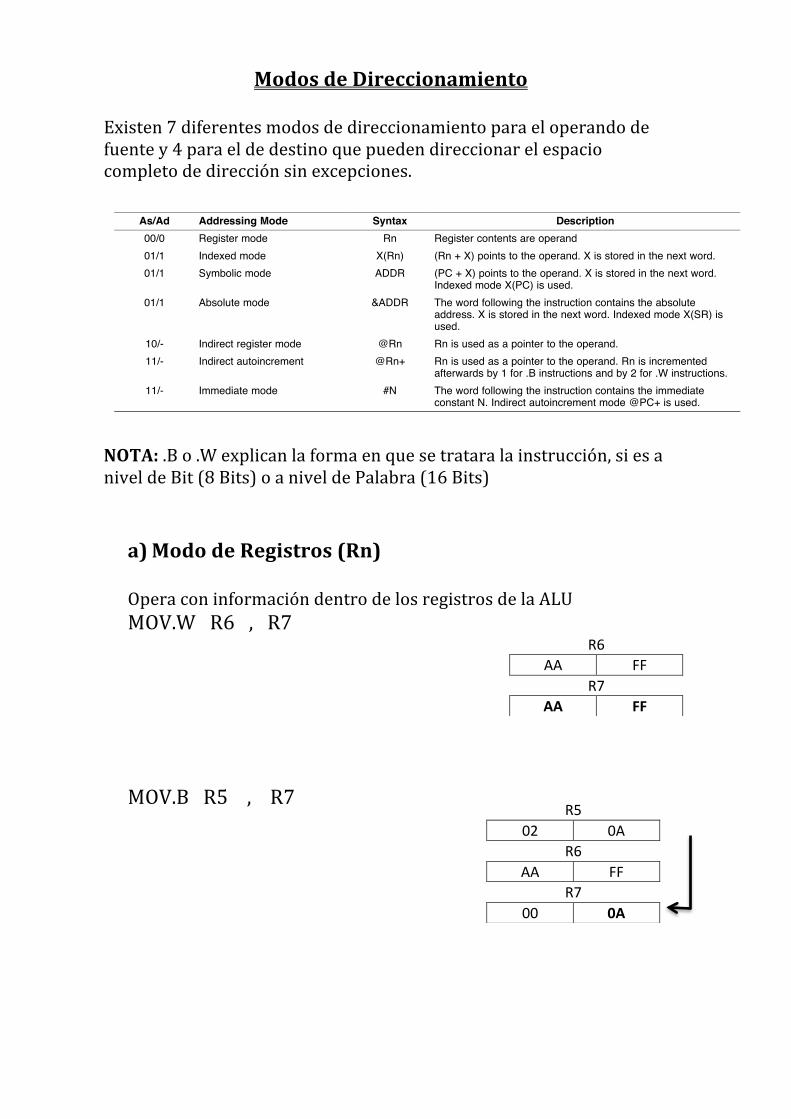
c) Modo Simbolico EDE=0X201 TONY=0X206
MOV.W TONY , 2(R4)
R4 21 DC
R5 02 0A
R6
BH 0X21 0x020D
BL 0XDC 0x020C
R6 AA FF
R7 00 0A
BH 0XFF 0x020D BL 0XDC 0x020C
0x020B
R4 02 00
BH 0X20 0x0207 BL 0X00 0x0206
0x0205 0x0204
0X20 0x0203 0X00 0x0202
2+ 0X020A
2+ 0X020C Dato
0X21DC
0XAAFF 4+ 0X020A= 0X020D
Dato
0XFF
0X206 Dir de mem
Dato
2 +0X200
0X202 0X2000
MOV.B TONY , EDE
d) Modo Absoluto (&)
Se usa en Registros de los subsistemas del Microcontrolador
MOV.W &TONY , 2(R4)
MOV.B &TONY , &EDE
e) Modo de Registro Indirecto @Rn
MOV.W @R4 , R7
BH 0X20 0x0207 BL 0X00 0x0206
0x0205 0x0204
0x0203
0x0202 0X00 0X201
R4 02 00
0X206 Dir de mem
Dato
0X201
0X00
2 +0X200= 0x202 0X206
Dato
0X2000
0x201 0X206
Dato
0X00
0X200 Dato

MOV.B @R5 , 4(R5) f) Modo Indirecto de Registro Auto-‐Incrementado @Rn+ MOV.W @R4++2 , R7 MOV.B @R5++1 , R7 g) Modo Inmediato #
MOV.W #0X3575 , 0(R4) MOV.B #0XFF, EDE MOV.W #EDE , R4 EDE=0X201
0X20A
Dato
0X20
0X20A
Dato
0X00FF
0X207
Dato
0X00

SET DE INSTRUCCIONES El set completo del MSP430 consiste en 27 instrucciones de Nucleo y 24 instrucciones emuladas. Hay 3 formatos para las instrucciones de Nucleo:
Ø Operando Doble Ø Operando Simple Ø Salto
Todas las instrucciones de operando Simple y de Doble Operando pueden ser instrucciones usadas como byte o palabra mediante las extensiones .B o .W. Si no se usa una extensión, la instrucción es una instrucción de palabra.
0xxx
4xxx
8xxx
Cxxx
1xxx
14xx
18xx
1Cxx
20xx
24xx
28xx
2Cxx
30xx
34xx
38xx
3Cxx
4xxx
5xxx
6xxx
7xxx
8xxx
9xxx
Axxx
Bxxx
Cxxx
Dxxx
Exxx
Fxxx
RRC RRC.B SWPB RRA RRA.B SXT PUSH PUSH.B CALL RETI
000 040 080 0C0 100 140 180 1C0 200 240 280 2C0 300 340 380 3C0
JNE/JNZ
JEQ/JZ
JNC
JC
JN
JGE
JL
JMP
MOV, MOV.B
ADD, ADD.B
ADDC, ADDC.B
SUBC, SUBC.B
SUB, SUB.B
CMP, CMP.B
DADD, DADD.B
BIT, BIT.B
BIC, BIC.B
BIS, BIS.B
XOR, XOR.B
AND, AND.B
Instruction Set www.ti.com
3.4.5 Instruction Set DescriptionThe instruction map is shown in Figure 3-12 and the complete instruction set is summarized in Table 3-17.
Figure 3-12. Core Instruction Map
Table 3-17. MSP430 Instruction SetMnemonic Description V N Z C
ADC(.B) (1) dst Add C to destination dst + C dst * * * *ADD(.B) src,dst Add source to destination src + dst dst * * * *ADDC(.B) src,dst Add source and C to destination src + dst + C dst * * * *AND(.B) src,dst AND source and destination src .and. dst dst 0 * * *BIC(.B) src,dst Clear bits in destination not.src .and. dst dst - - - -BIS(.B) src,dst Set bits in destination src .or. dst dst - - - -BIT(.B) src,dst Test bits in destination src .and. dst 0 * * *BR (1) dst Branch to destination dst PC - - - -CALL dst Call destination PC+2 stack, dst PC - - - -CLR(.B) (1) dst Clear destination 0 dst - - - -CLRC (1) Clear C 0 C - - - 0CLRN (1) Clear N 0 N - 0 - -CLRZ (1) Clear Z 0 Z - - 0 -CMP(.B) src,dst Compare source and destination dst - src * * * *DADC(.B) (1) dst Add C decimally to destination dst + C dst (decimally) * * * *DADD(.B) src,dst Add source and C decimally to dst src + dst + C dst (decimally) * * * *DEC(.B) (1) dst Decrement destination dst - 1 dst * * * *
(1) Emulated Instruction
64 CPU SLAU144H December 2004 Revised April 2011Submit Documentation Feedback
Copyright 2004 2011, Texas Instruments Incorporated
www.ti.com Instruction Set
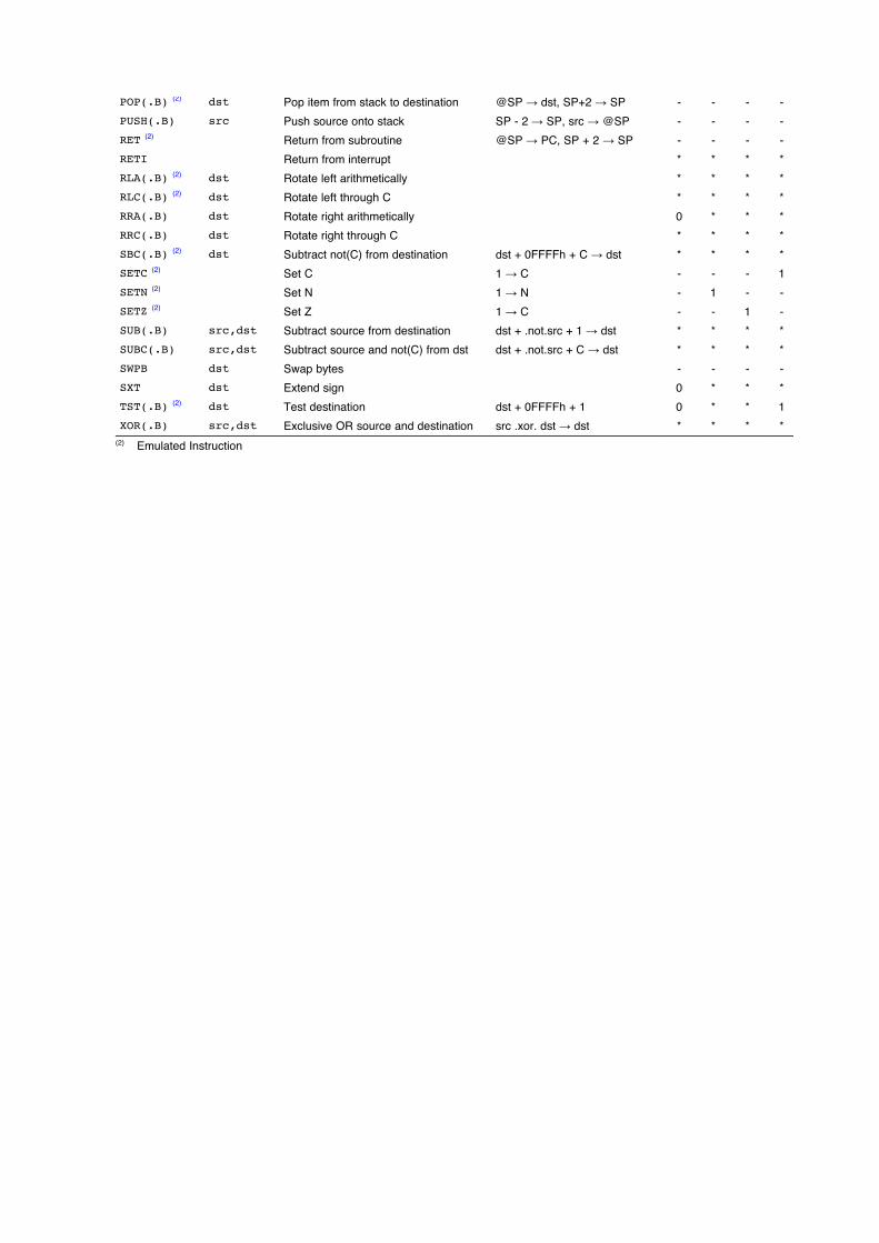
Table 3-17. MSP430 Instruction Set (continued)Mnemonic Description V N Z C
DECD(.B) (1) dst Double-decrement destination dst - 2 dst * * * *DINT (1) Disable interrupts 0 GIE - - - -EINT (1) Enable interrupts 1 GIE - - - -INC(.B) (1) dst Increment destination dst +1 dst * * * *INCD(.B) (1) dst Double-increment destination dst+2 dst * * * *INV(.B) (1) dst Invert destination .not.dst dst * * * *JC/JHS label Jump if C set/Jump if higher or same - - - -JEQ/JZ label Jump if equal/Jump if Z set - - - -JGE label Jump if greater or equal - - - -JL label Jump if less - - - -JMP label Jump PC + 2 offset PC - - - -JN label Jump if N set - - - -JNC/JLO label Jump if C not set/Jump if lower - - - -JNE/JNZ label Jump if not equal/Jump if Z not set - - - -MOV(.B) src,dst Move source to destination src dst - - - -NOP (2) No operation - - - -POP(.B) (2) dst Pop item from stack to destination @SP dst, SP+2 SP - - - -PUSH(.B) src Push source onto stack SP - 2 SP, src @SP - - - -RET (2) Return from subroutine @SP PC, SP + 2 SP - - - -RETI Return from interrupt * * * *RLA(.B) (2) dst Rotate left arithmetically * * * *RLC(.B) (2) dst Rotate left through C * * * *RRA(.B) dst Rotate right arithmetically 0 * * *RRC(.B) dst Rotate right through C * * * *SBC(.B) (2) dst Subtract not(C) from destination dst + 0FFFFh + C dst * * * *SETC (2) Set C 1 C - - - 1SETN (2) Set N 1 N - 1 - -SETZ (2) Set Z 1 C - - 1 -SUB(.B) src,dst Subtract source from destination dst + .not.src + 1 dst * * * *SUBC(.B) src,dst Subtract source and not(C) from dst dst + .not.src + C dst * * * *SWPB dst Swap bytes - - - -SXT dst Extend sign 0 * * *TST(.B) (2) dst Test destination dst + 0FFFFh + 1 0 * * 1XOR(.B) src,dst Exclusive OR source and destination src .xor. dst dst * * * *(2) Emulated Instruction
65SLAU144H December 2004 Revised April 2011 CPUSubmit Documentation Feedback
Copyright 2004 2011, Texas Instruments Incorporated
www.ti.com Instruction Set
Table 3-17. MSP430 Instruction Set (continued)Mnemonic Description V N Z C
DECD(.B) (1) dst Double-decrement destination dst - 2 dst * * * *DINT (1) Disable interrupts 0 GIE - - - -EINT (1) Enable interrupts 1 GIE - - - -INC(.B) (1) dst Increment destination dst +1 dst * * * *INCD(.B) (1) dst Double-increment destination dst+2 dst * * * *INV(.B) (1) dst Invert destination .not.dst dst * * * *JC/JHS label Jump if C set/Jump if higher or same - - - -JEQ/JZ label Jump if equal/Jump if Z set - - - -JGE label Jump if greater or equal - - - -JL label Jump if less - - - -JMP label Jump PC + 2 offset PC - - - -JN label Jump if N set - - - -JNC/JLO label Jump if C not set/Jump if lower - - - -JNE/JNZ label Jump if not equal/Jump if Z not set - - - -MOV(.B) src,dst Move source to destination src dst - - - -NOP (2) No operation - - - -POP(.B) (2) dst Pop item from stack to destination @SP dst, SP+2 SP - - - -PUSH(.B) src Push source onto stack SP - 2 SP, src @SP - - - -RET (2) Return from subroutine @SP PC, SP + 2 SP - - - -RETI Return from interrupt * * * *RLA(.B) (2) dst Rotate left arithmetically * * * *RLC(.B) (2) dst Rotate left through C * * * *RRA(.B) dst Rotate right arithmetically 0 * * *RRC(.B) dst Rotate right through C * * * *SBC(.B) (2) dst Subtract not(C) from destination dst + 0FFFFh + C dst * * * *SETC (2) Set C 1 C - - - 1SETN (2) Set N 1 N - 1 - -SETZ (2) Set Z 1 C - - 1 -SUB(.B) src,dst Subtract source from destination dst + .not.src + 1 dst * * * *SUBC(.B) src,dst Subtract source and not(C) from dst dst + .not.src + C dst * * * *SWPB dst Swap bytes - - - -SXT dst Extend sign 0 * * *TST(.B) (2) dst Test destination dst + 0FFFFh + 1 0 * * 1XOR(.B) src,dst Exclusive OR source and destination src .xor. dst dst * * * *(2) Emulated Instruction
65SLAU144H December 2004 Revised April 2011 CPUSubmit Documentation Feedback
Copyright 2004 2011, Texas Instruments Incorporated

Ø Instrucciones de Formato Doble En el siguiente listado se pueden apreciar las instrucciones que gozan de este formato.
Ejemplos de el uso de algunas instrucciones de Doble formato usando algunos modos de Direccionamiento previamente vistos: MOV.B #0X00, &P2SEL MOV.W #DATOS, R5 MOV.B @R5+,&PIOUT MOV.W #49998,R4 MOV.B &P2IN,R5 CMP.B #0XC0,R5 BIC.B #BIT6 + BIT7,&P2DIR BIS.B #0XFF, &P1DIR AND.B #0XC0,R5
www.ti.com Instruction Set
3.4.1 Double-Operand (Format I) InstructionsFigure 3-9 illustrates the double-operand instruction format.
15 14 13 12 11 10 9 8 7 6 5 4 3 2 1 0Op-code S-Reg Ad B/W As D-Reg
Figure 3-9. Double Operand Instruction Format
Table 3-11 lists and describes the double operand instructions.
Table 3-11. Double Operand InstructionsStatus BitsS-Reg,Mnemonic OperationD-Reg V N Z C
src dst - - - -MOV(.B) src,dstsrc + dst dst * * * *ADD(.B) src,dstsrc + dst + C dst * * * *ADDC(.B) src,dstdst + .not.src + 1 dst * * * *SUB(.B) src,dstdst + .not.src + C dst * * * *SUBC(.B) src,dstdst - src * * * *CMP(.B) src,dstsrc + dst + C dst (decimally) * * * *DADD(.B) src,dstsrc .and. dst 0 * * *BIT(.B) src,dstnot.src .and. dst dst - - - -BIC(.B) src,dstsrc .or. dst dst - - - -BIS(.B) src,dstsrc .xor. dst dst * * * *XOR(.B) src,dstsrc .and. dst dst 0 * * *AND(.B) src,dst
* The status bit is affectedThe status bit is not affected
0 The status bit is cleared1 The status bit is set
NOTE: Instructions CMP and SUBThe instructions CMP and SUB are identical except for the storage of the result. The same istrue for the BIT and AND instructions.
59SLAU144H December 2004 Revised April 2011 CPUSubmit Documentation Feedback
Copyright 2004 2011, Texas Instruments Incorporated
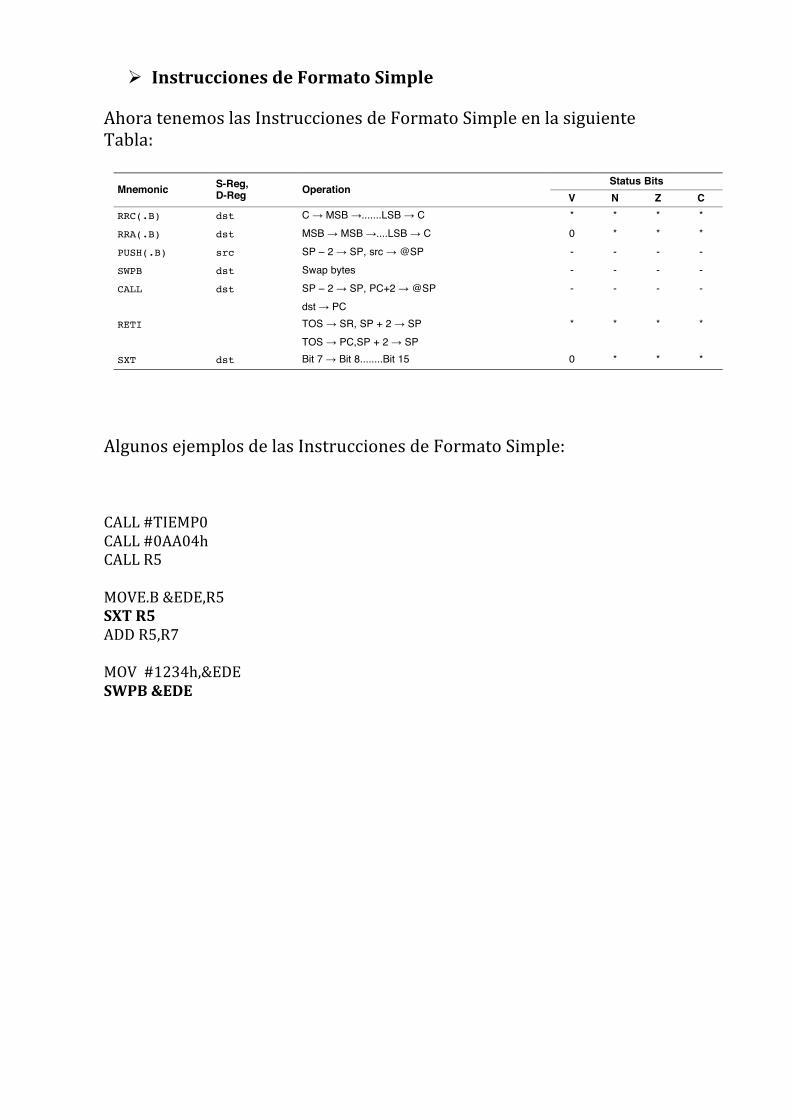
Ø Instrucciones de Formato Simple Ahora tenemos las Instrucciones de Formato Simple en la siguiente Tabla:
Algunos ejemplos de las Instrucciones de Formato Simple: CALL #TIEMP0 CALL #0AA04h CALL R5 MOVE.B &EDE,R5 SXT R5 ADD R5,R7 MOV #1234h,&EDE SWPB &EDE
Instruction Set www.ti.com
3.4.2 Single-Operand (Format II) InstructionsFigure 3-10 illustrates the single-operand instruction format.
15 14 13 12 11 10 9 8 7 6 5 4 3 2 1 0Op-code B/W Ad D/S-Reg
Figure 3-10. Single Operand Instruction Format
Table 3-12 lists and describes the single operand instructions.
Table 3-12. Single Operand InstructionsStatus BitsS-Reg,Mnemonic OperationD-Reg V N Z C
C MSB .......LSB C * * * *RRC(.B) dstMSB MSB ....LSB C 0 * * *RRA(.B) dstSP 2 SP, src @SP - - - -PUSH(.B) srcSwap bytes - - - -SWPB dstSP 2 SP, PC+2 @SP - - - -CALL dstdst PCTOS SR, SP + 2 SP * * * *RETITOS PC,SP + 2 SPBit 7 Bit 8........Bit 15 0 * * *SXT dst
* The status bit is affectedThe status bit is not affected
0 The status bit is cleared1 The status bit is set
All addressing modes are possible for the CALL instruction. If the symbolic mode (ADDRESS), theimmediate mode (#N), the absolute mode ( EDE) or the indexed mode x(RN) is used, the word thatfollows contains the address information.
60 CPU SLAU144H December 2004 Revised April 2011Submit Documentation Feedback
Copyright 2004 2011, Texas Instruments Incorporated

Ø Instrucciones de Salto Ahora podemos apreciar las Instrucciones de Salto en la siguiente Tabla:
Algunos ejemplos de la utilización de estas Instrucciones dentro de un programa: JMP APAGADO JNE ENCENDER JEQ INICIO JNZ TIEMPO
www.ti.com Instruction Set
3.4.3 JumpsFigure 3-11 shows the conditional-jump instruction format.
15 14 13 12 11 10 9 8 7 6 5 4 3 2 1 0Op-code C 10-Bit PC Offset
Figure 3-11. Jump Instruction Format
Table 3-13 lists and describes the jump instructions
Table 3-13. Jump InstructionsMnemonic S-Reg, D-Reg Operation
Jump to label if zero bit is setJEQ/JZ Label
Jump to label if zero bit is resetJNE/JNZ Label
Jump to label if carry bit is setJC Label
Jump to label if carry bit is resetJNC Label
Jump to label if negative bit is setJN Label
Jump to label if (N .XOR. V) = 0JGE Label
Jump to label if (N .XOR. V) = 1JL Label
Jump to label unconditionallyJMP Label
Conditional jumps support program branching relative to the PC and do not affect the status bits. Thepossible jump range is from 511 to +512 words relative to the PC value at the jump instruction. The10-bit program-counter offset is treated as a signed 10-bit value that is doubled and added to the programcounter:PCnew = PCold + 2 + PCoffset 2
61SLAU144H December 2004 Revised April 2011 CPUSubmit Documentation Feedback
Copyright 2004 2011, Texas Instruments Incorporated
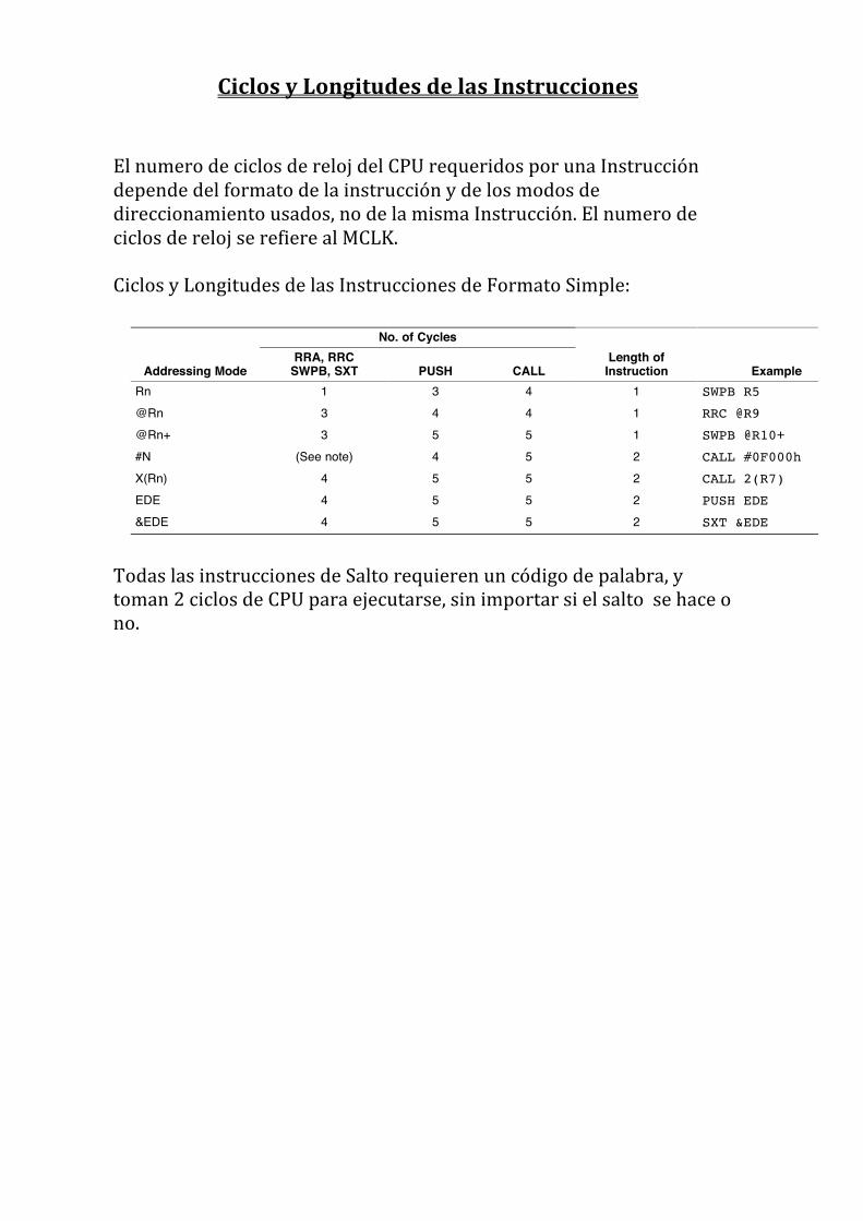
Ciclos y Longitudes de las Instrucciones
El numero de ciclos de reloj del CPU requeridos por una Instrucción depende del formato de la instrucción y de los modos de direccionamiento usados, no de la misma Instrucción. El numero de ciclos de reloj se refiere al MCLK. Ciclos y Longitudes de las Instrucciones de Formato Simple:
Todas las instrucciones de Salto requieren un código de palabra, y toman 2 ciclos de CPU para ejecutarse, sin importar si el salto se hace o no.
Instruction Set www.ti.com
3.4.4 Instruction Cycles and LengthsThe number of CPU clock cycles required for an instruction depends on the instruction format and theaddressing modes used - not the instruction itself. The number of clock cycles refers to the MCLK.
3.4.4.1 Interrupt and Reset CyclesTable 3-14 lists the CPU cycles for interrupt overhead and reset.
Table 3-14. Interrupt and Reset CyclesAction No. of Cycles Length of InstructionReturn from interrupt (RETI) 5 1Interrupt accepted 6 -WDT reset 4 -Reset (RST/NMI) 4 -
3.4.4.2 Format-II (Single Operand) Instruction Cycles and LengthsTable 3-15 lists the length and CPU cycles for all addressing modes of format-II instructions.
Table 3-15. Format-II Instruction Cycles and LengthsNo. of Cycles
RRA, RRC Length ofAddressing Mode SWPB, SXT PUSH CALL Instruction Example
Rn 1 3 4 1 SWPB R5@Rn 3 4 4 1 RRC @R9@Rn+ 3 5 5 1 SWPB @R10+#N (See note) 4 5 2 CALL #0F000hX(Rn) 4 5 5 2 CALL 2(R7)EDE 4 5 5 2 PUSH EDEEDE 4 5 5 2 SXT &EDE
NOTE: Instruction Format II Immediate ModeDo not use instruction RRA, RRC, SWPB, and SXT with the immediate mode in the destinationfield. Use of these in the immediate mode results in an unpredictable program operation.
3.4.4.3 Format-III (Jump) Instruction Cycles and LengthsAll jump instructions require one code word, and take two CPU cycles to execute, regardless of whetherthe jump is taken or not.
62 CPU SLAU144H December 2004 Revised April 2011Submit Documentation Feedback
Copyright 2004 2011, Texas Instruments Incorporated
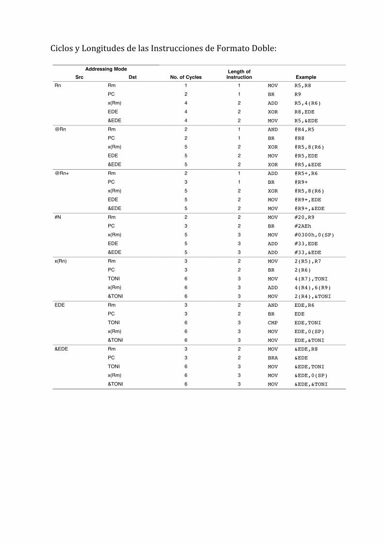
Ciclos y Longitudes de las Instrucciones de Formato Doble:
www.ti.com Instruction Set
3.4.4.4 Format-I (Double Operand) Instruction Cycles and LengthsTable 3-16 lists the length and CPU cycles for all addressing modes of format-I instructions.
Table 3-16. Format 1 Instruction Cycles and LengthsAddressing Mode Length of
Src Dst No. of Cycles Instruction ExampleRn Rm 1 1 MOV R5,R8
PC 2 1 BR R9x(Rm) 4 2 ADD R5,4(R6)EDE 4 2 XOR R8,EDEEDE 4 2 MOV R5,&EDE
@Rn Rm 2 1 AND @R4,R5PC 2 1 BR @R8x(Rm) 5 2 XOR @R5,8(R6)EDE 5 2 MOV @R5,EDEEDE 5 2 XOR @R5,&EDE
@Rn+ Rm 2 1 ADD @R5+,R6PC 3 1 BR @R9+x(Rm) 5 2 XOR @R5,8(R6)EDE 5 2 MOV @R9+,EDEEDE 5 2 MOV @R9+,&EDE
#N Rm 2 2 MOV #20,R9PC 3 2 BR #2AEhx(Rm) 5 3 MOV #0300h,0(SP)EDE 5 3 ADD #33,EDEEDE 5 3 ADD #33,&EDE
x(Rn) Rm 3 2 MOV 2(R5),R7PC 3 2 BR 2(R6)TONI 6 3 MOV 4(R7),TONIx(Rm) 6 3 ADD 4(R4),6(R9)TONI 6 3 MOV 2(R4),&TONI
EDE Rm 3 2 AND EDE,R6PC 3 2 BR EDETONI 6 3 CMP EDE,TONIx(Rm) 6 3 MOV EDE,0(SP)TONI 6 3 MOV EDE,&TONI
EDE Rm 3 2 MOV &EDE,R8PC 3 2 BRA &EDETONI 6 3 MOV &EDE,TONIx(Rm) 6 3 MOV &EDE,0(SP)TONI 6 3 MOV &EDE,&TONI
63SLAU144H December 2004 Revised April 2011 CPUSubmit Documentation Feedback
Copyright 2004 2011, Texas Instruments Incorporated
Top Related