7081010100 CADB-T-HE ECOWATT
72
CADB/T-HE ECOWATT
Transcript of 7081010100 CADB-T-HE ECOWATT

CADB/T-HE ECOWATT

2
ES
PA
ÑO
L
ÍNDICE
1. GENERALIDADES .......................................................................................................................................................3
2. NORMAS DE SEGURIDAD Y MARCADO “CE” .............................................................................................................3
3. NORMAS GENERALES ...............................................................................................................................................3
4. ETIQUETADO DE LA UNIDAD .....................................................................................................................................3
5. MANIPULACIÓN .........................................................................................................................................................4
6. INSTALACIÓN .............................................................................................................................................................5
6.1. Generalidades ......................................................................................................................................................5
6.1.1. Instalación en intemperie .........................................................................................................................8
6.2. Dimensiones y cotas libres para mantenimiento ...............................................................................................9
6.3. Características de la gama ................................................................................................................................11
6.4. Conexiones .........................................................................................................................................................11
6.4.1. Conexión canalizaciones .........................................................................................................................11
6.4.1.1. Conexión canalización de aire ....................................................................................................11
6.4.1.2. Conexión canalización baterías de agua. Versiones DC ............................................................12
6.4.1.3. Evacuación de condensados ......................................................................................................12
6.4.2. Conexiones eléctricas .............................................................................................................................13
6.4.2.1. Conexionado de los motores ......................................................................................................13
6.4.2.2. Conexión del by-pass .................................................................................................................14
6.4.2.3. Conexión de las resistencias eléctricas .....................................................................................15
6.4.2.4. Conexión de accesorios eléctricos .............................................................................................17
6.4.2.4.1. Control VAV (Caudal variable), ajuste manual ............................................................17
6.4.2.4.2. Control VAV (Caudal variable), mediante sensor de CO2 o similar ............................18
6.4.2.4.3. Control COP y CAV ......................................................................................................21
6.4.2.4.4. Control COP (Presión constante) ................................................................................24
6.4.2.4.5. Conexión de presostatos ............................................................................................29
6.5. Inversion del lado impulsión / extracción de aire (Solo versión –D) .................................................................29
6.6. Confi guraciones .................................................................................................................................................30
7. INSPECCIÓN, MANTENIMIENTO Y LIMPIEZA ..........................................................................................................32
7.1. Sustitución de fi ltros ..........................................................................................................................................32
7.2. Montaje fi ltros ....................................................................................................................................................33
7.3. Intercambiador de calor ....................................................................................................................................34
7.4. Tubo de desagüe de condensados .....................................................................................................................35
8. ANOMALÍAS DE FUNCIONAMIENTO ........................................................................................................................36
8.1. Anomalías generales .........................................................................................................................................36
ESPAÑOL
3
ES
PA
ÑO
L
1. GENERALIDADES
Le agradecemos la confi anza que ha depositado en nosotros mediante la compra de este aparato.
Usted ha adquirido un producto de calidad que ha sido totalmente fabricado según las reglas técnicas
de seguridad reconocidas y conformes a las normas de la CE.
Lea atentamente el contenido del presente libro de instrucciones, pues contiene indicaciones impor-
tantes para su seguridad durante la instalación, el uso y el mantenimiento de este producto.
Consérvelo para una posible consulta posterior.
Rogamos compruebe el perfecto estado del aparato al desembalarlo, ya que cualquier defecto de
origen que presente, está amparado por la garantía S&P.
2. NORMAS DE SEGURIDAD Y MARCADO “CE”
Los técnicos de S&P están fi rmemente comprometidos en la investigación y desarrollo de productos
cada vez más efi cientes y que cumplan con las normas de seguridad en vigor.
Las normas y recomendaciones que se indican a continuación, refl ejan las normas vigentes, preferen-
temente en materia de seguridad y por lo tanto se basan principalmente en el cumplimiento de las
normas de carácter general. Por consiguiente, recomendamos a todas las personas expuestas a ries-
gos que se atengan escrupulosamente a las normas de prevención de accidentes en vigor en su país.
S&P queda eximido de cualquier responsabilidad por eventuales daños causados a personas y cosas
derivados de la falta de cumplimiento de las normas de seguridad, así como de posibles modifi cacio-
nes en el producto.
El sello CE y la correspondiente declaración de conformidad, atestiguan la conformidad con las nor-
mas comunitarias aplicables.
3. NORMAS GENERALES
Se ha realizado el análisis de los riesgos del producto como está previsto en la Directiva de Máquinas.
Este manual contiene la información destinada a todo el personal expuesto, con el fi n de prevenir po-
sibles daños a personas y/o cosas, a causa de una defectuosa manipulación o mantenimiento.
Todas las intervenciones de mantenimiento (ordinario y extraordinario) deben ser realizadas con la
máquina parada y la alimentación eléctrica desconectada.
Para evitar el peligro de posible arranque accidental, ponga en el cuadro eléctrico central y en la con-
sola de control, carteles de advertencia con el siguiente contenido:
“Atención: control desconectado para operaciones de mantenimiento”
Antes de conectar el cable de alimentación eléctrica a la regleta, verifi que que la tensión de la línea
corresponde a la indicada en la placa de características de la unidad. Verifi que periódicamente las
etiquetas del producto. Si con el paso del tiempo son ilegibles, deben ser sustituidas.
4. ETIQUETADO DE LA UNIDAD
La máquina puede estar provista de diversos pictogramas de señalización, que no deben ser elimina-
dos. Las señales se dividen en:
• Señales de prohibición: No reparar o ajustar durante el funcionamiento.
• Señales de peligro: Señala la presencia de elementos con tensión en el interior del contenedor
sobre el que aparece el cartel.
• Señales de identifi cación: Tarjeta CE, indica los datos del producto y dirección del fabricante. La
marca CE, indica la conformidad del producto, según las normas CEE.
4
ES
PA
ÑO
L
Señal de peligro Señal de prohibición
5. MANIPULACIÓN
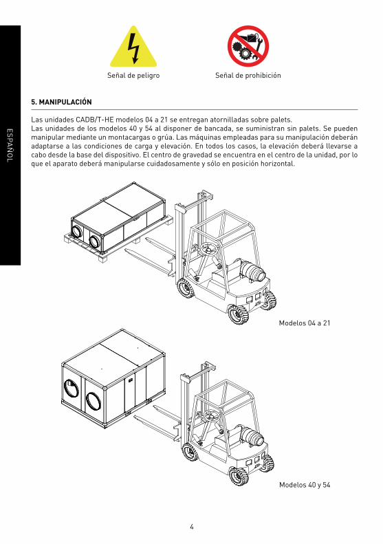
Las unidades CADB/T-HE modelos 04 a 21 se entregan atornilladas sobre palets.
Las unidades de los modelos 40 y 54 al disponer de bancada, se suministran sin palets. Se pueden
manipular mediante un montacargas o grúa. Las máquinas empleadas para su manipulación deberán
adaptarse a las condiciones de carga y elevación. En todos los casos, la elevación deberá llevarse a
cabo desde la base del dispositivo. El centro de gravedad se encuentra en el centro de la unidad, por lo
que el aparato deberá manipularse cuidadosamente y sólo en posición horizontal.
Modelos 04 a 21
Modelos 40 y 54

5
ES
PA
ÑO
L
6. INSTALACIÓN
6.1. GENERALIDADES
Modelos Horizontales de los tamaños 04, 08, 16 y 21
Estos modelos están diseñados para ser instalados colgados del techo o ubicados en un falso techo.
Los modelos 04, 08, 16 y 21 tienen seis estribos metálicos ubicados en cada una de las esquinas infe-
riores y dos de ellos centrados en los perfi les superiores. Se recomienda realizar la soportación del
recuperador al techo y su nivelado, mediante varillas roscadas de Ø8 mm según imagen:
El instalador debe asegurarse de que la estructura del techo, así como la fi jación al mismo, pueden
soportar el peso del aparato a instalar, teniendo en cuenta que se trata de una carga dinámica.
Para evitar la transmisión de vibraciones del equipo al resto de la instalación, es imprescindible que
el instalador utilice elementos atenuadores de las vibraciones, tales como soportes antivibradores de
goma o muelles en los apoyos de la unidad, acoplamiento elástico entre el equipo y las conducciones
de aire y manguitos elásticos en las tuberías de agua.
Modelo Peso (kg)
4 147
8 183
16 235
21 333
Modelos Verticales de los tamaños 40 y 54
Los modelos verticales del tamaño 40 y 54 se suministran con bancada perimetral. Se deberán insta-
lar en una superfi cie plana y no se pueden colgar. La bancada debe estar en contacto con el suelo, o
con una superfície plana. Es indispensable que el peso del equipo se encuentre distribuido entre todos
los puntos de apoyo para evitar deformaciones.
El instalador debe asegurarse de que el suelo o la estructura que sirve de apoyo del equipo, pueden
soportar el peso del aparato a instalar, teniendo en cuenta que es una carga dinámica.

6
ES
PA
ÑO
L
Modelo Peso (kg)
40 597
54 730
Modelos Horizontales de los tamaños 40 y 54
¡IMPORTANTE!Particularidades en la instalación de las versiones horizontales LH y RH
Para que se produzca la correcta evacuación de los condensados generados en el interior del inter-
cambiador de calor, es necesario que el equipo se instale con una inclinación mínima de 3º hacia el
lado donde se encuentra el ventilador de expulsión de aire al exterior:
VENTILADOR
DE IMPULSIÓN VENTILADOR
DE EXTRACCIÓN
Los modelos de confi guración horizontal se suministran con bancada perimetral. Es indispensable
que el peso del equipo se encuentre distribuido entre todos los puntos de apoyo para evitar deforma-
ciones.
El instalador debe asegurarse de que el suelo o la estructura que sirve de apoyo del equipo, pueden
soportar el peso del aparato a instalar, teniendo en cuenta que es una carga dinámica.
Modelo Peso (kg)
40 597
54 730

7
ES
PA
ÑO
L
Para todas las confi guraciones
Una vez asegurado el aparato en la posición correcta, el instalador debe realizar la conexión con la
canalización de aire, la conexión a la red eléctrica, y en el caso de versiones con batería de agua, la
conexión con el circuito cerrado de agua caliente de la batería de agua.
En el interior del equipo se suministran los siguientes accesorios:
Desagüe (Fig.1)
a)
b)c)
x2 x2 x2 x1
Manual
Desagüe (Fig.1)
a) Tubo desagüe
b) Tuerca
c) Junta
Montar los dos desagües tal y como se indica en los dibujos siguientes:
a) Versiones horizontales de los modelos CADB/T HE 04 a 21
b) Versiones horizontales de los modelos CADB/T HE 40 y 54

8
ES
PA
ÑO
L
c) Versiones de los modelos CADB/T HE 40 y 54
En estas versiones el desagüe y su correspondiente sifón se suministran montados en el equipo.
6.1.1. Instalación en intemperie
La gama CADB/T-HE ECOWATT está diseñada para ir montada en interior. En caso de montaje
en exterior, será necesario ubicar el equipo bajo cubierta que ofrezca protección sufi ciente para
evitar la caída directa de lluvia sobre el equipo o bien instalar el correspondiente tejadillo para
montaje.
En el caso de los equipos horizontales modelos 04 a 21, deberá garantizarse espacio sufi ciente
bajo el equipo de forma que sea posible instalar los correspondientes sifones en las salidas de
condensados de los equipos.

9
ES
PA
ÑO
L
6.2. DIMENSIONES Y COTAS LIBRES PARA MANTENIMIENTO
a) Versiones horizontales de los modelos CADB/T HE 04 a 21
Cotas libres para mantenimiento en instalaciones con acceso por paneles laterales
Cotas libres para mantenimiento en instalaciones con acceso por paneles inferiores
Cotas para instalación falso techo
Modelo W H L A B C Ø E F Peso
(kg)
04 760 375 1520 400 400 700 200 350 920 147
08 910 425 1750 450 400 860 250 400 950 183
16 1240 450 1950 600 500 1190 315 400 1150 235
21 1640 550 2300 800 700 1590 400 500 1300 333
Conf. LH
Conf. LH
Conf. RH
Conf. RH

10
ES
PA
ÑO
L
b) Versiones horizontales de los modelos CADB/T HE 40 y 54
Conf. LH
Conf. RH
Instalación suelo
Modelo W H L A B Ø Peso
(kg)
40 1500 1200 2100 400 600 450 597
54 1550 1580 2250 400 750 500 730
c) Versiones verticales de los modelos CADB/T HE 40 y 54
Conf. LV
Conf. RV
Modelo W H L A B Ø Peso
(kg)
40 1120 1580 2100 400 1100 450 597
54 1500 1630 2250 400 1450 500 730
11
ES
PA
ÑO
L
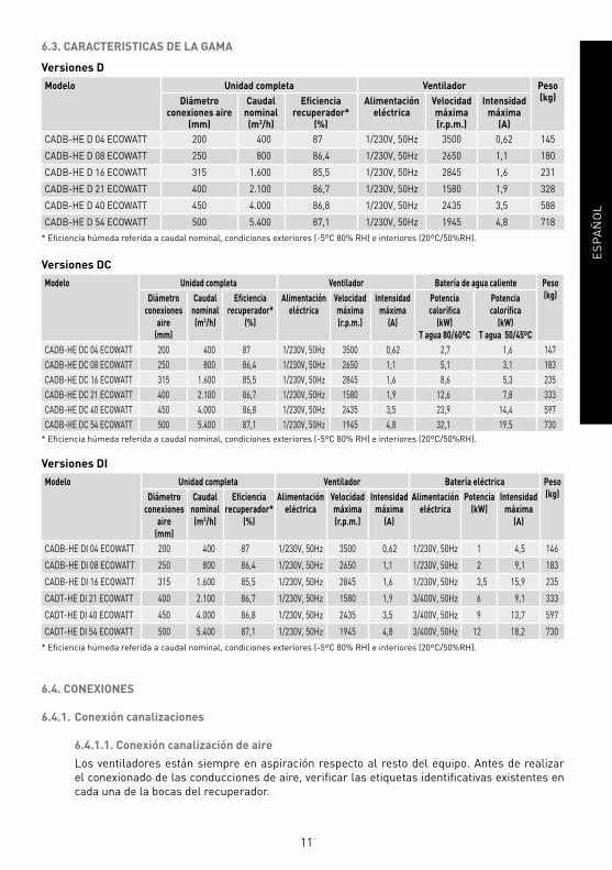
6.3. CARACTERISTICAS DE LA GAMA
Versiones D
Modelo Unidad completa Ventilador Peso (kg)Diámetro
conexiones aire (mm)
Caudal nominal(m3/h)
Efi ciencia recuperador*
(%)
Alimentación eléctrica
Velocidadmáxima(r.p.m.)
Intensidadmáxima
(A)
CADB-HE D 04 ECOWATT 200 400 87 1/230V, 50Hz 3500 0,62 145
CADB-HE D 08 ECOWATT 250 800 86,4 1/230V, 50Hz 2650 1,1 180
CADB-HE D 16 ECOWATT 315 1.600 85,5 1/230V, 50Hz 2845 1,6 231
CADB-HE D 21 ECOWATT 400 2.100 86,7 1/230V, 50Hz 1580 1,9 328
CADB-HE D 40 ECOWATT 450 4.000 86,8 1/230V, 50Hz 2435 3,5 588
CADB-HE D 54 ECOWATT 500 5.400 87,1 1/230V, 50Hz 1945 4,8 718
* Efi ciencia húmeda referida a caudal nominal, condiciones exteriores (-5ºC 80% RH) e interiores (20ºC/50%RH).
Versiones DC
Modelo Unidad completa Ventilador Batería de agua caliente Peso
(kg)Diámetro
conexiones
aire
(mm)
Caudal
nominal
(m3/h)
Efi ciencia
recuperador*
(%)
Alimentación
eléctrica
Velocidad
máxima
(r.p.m.)
Intensidad
máxima
(A)
Potencia
calorífi ca
(kW)
T agua 80/60ºC
Potencia
calorífi ca
(kW)
T agua 50/45ºC
CADB-HE DC 04 ECOWATT 200 400 87 1/230V, 50Hz 3500 0,62 2,7 1,6 147
CADB-HE DC 08 ECOWATT 250 800 86,4 1/230V, 50Hz 2650 1,1 5,1 3,1 183
CADB-HE DC 16 ECOWATT 315 1.600 85,5 1/230V, 50Hz 2845 1,6 8,6 5,3 235
CADB-HE DC 21 ECOWATT 400 2.100 86,7 1/230V, 50Hz 1580 1,9 12,6 7,8 333
CADB-HE DC 40 ECOWATT 450 4.000 86,8 1/230V, 50Hz 2435 3,5 23,9 14,4 597
CADB-HE DC 54 ECOWATT 500 5.400 87,1 1/230V, 50Hz 1945 4,8 32,1 19,5 730
* Efi ciencia húmeda referida a caudal nominal, condiciones exteriores (-5ºC 80% RH) e interiores (20ºC/50%RH).
Versiones DI
Modelo Unidad completa Ventilador Batería eléctrica Peso
(kg)Diámetro
conexiones
aire
(mm)
Caudal
nominal
(m3/h)
Efi ciencia
recuperador*
(%)
Alimentación
eléctrica
Velocidad
máxima
(r.p.m.)
Intensidad
máxima
(A)
Alimentación
eléctrica
Potencia
(kW)
Intensidad
máxima
(A)
CADB-HE DI 04 ECOWATT 200 400 87 1/230V, 50Hz 3500 0,62 1/230V, 50Hz 1 4,5 146
CADB-HE DI 08 ECOWATT 250 800 86,4 1/230V, 50Hz 2650 1,1 1/230V, 50Hz 2 9,1 183
CADB-HE DI 16 ECOWATT 315 1.600 85,5 1/230V, 50Hz 2845 1,6 1/230V, 50Hz 3,5 15,9 235
CADT-HE DI 21 ECOWATT 400 2.100 86,7 1/230V, 50Hz 1580 1,9 3/400V, 50Hz 6 9,1 333
CADT-HE DI 40 ECOWATT 450 4.000 86,8 1/230V, 50Hz 2435 3,5 3/400V, 50Hz 9 13,7 597
CADT-HE DI 54 ECOWATT 500 5.400 87,1 1/230V, 50Hz 1945 4,8 3/400V, 50Hz 12 18,2 730
* Efi ciencia húmeda referida a caudal nominal, condiciones exteriores (-5ºC 80% RH) e interiores (20ºC/50%RH).
6.4. CONEXIONES
6.4.1. Conexión canalizaciones
6.4.1.1. Conexión canalización de aire
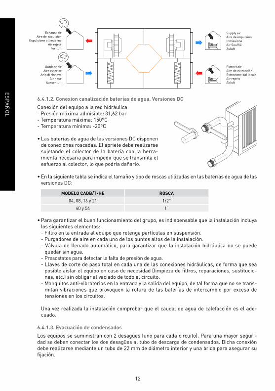
Los ventiladores están siempre en aspiración respecto al resto del equipo. Antes de realizar
el conexionado de las conducciones de aire, verifi car las etiquetas identifi cativas existentes en
cada una de la bocas del recuperador.
12
ES
PA
ÑO
L
Outdoor air
Aire exterior
Aria di rinnovo
Air neur
Aussenluft
Extract air
Aire de extracción
Estrazione dal locale
Air repris
Abluft
Exhaust air
Aire de expulsión
Espulsione all esterno
Air rejeté
Fortluft
Supply air
Aire de impulsión
Inmissione
Air Souffl é
Zuluft
6.4.1.2. Conexion canalización baterías de agua. Versiones DC
Conexión del equipo a la red hidráulica
- Presión máxima admisible: 31,62 bar
- Temperatura máxima: 150°C
- Temperatura mínima: -20ºC
• Las baterías de agua de las versiones DC disponen
de conexiones roscadas. El apriete debe realizarse
sujetando el colector de la batería con la herra-
mienta necesaria para impedir que se transmita el
esfuerzo al colector, lo que podría dañarlo.
• En la siguiente tabla se indica el tamaño y tipo de roscas utilizadas en las baterías de agua de las
versiones DC:
MODELO CADB/T-HE ROSCA
04, 08, 16 y 21 1/2”
40 y 54 1”
• Para garantizar el buen funcionamiento del grupo, es indispensable que la instalación incluya
los siguientes elementos:
- Filtro en la entrada al equipo que retenga partículas en suspensión.
- Purgadores de aire en cada uno de los puntos altos de la instalación.
- Válvula de llenado automático, para garantizar que la instalación hidráulica no se puede
quedar sin agua.
- Presostatos para detectar la falta de presión de agua.
- Llaves de corte de paso total en cada una de las conexiones hidráulicas, de forma que sea
posible aislar el equipo en caso de necesidad (limpieza de fi ltros, reparaciones, sustitucio-
nes, etc.) sin obligar al vaciado de todo el circuito.
- Manguitos anti-vibratorios en la entrada y la salida del equipo, de tal forma que no se trans-
mitan vibraciones que provoquen la rotura de las baterías de intercambio por exceso de
tensiones en los circuitos.
Una vez realizada la instalación comprobar que el caudal de agua de calefacción es el ade-
cuado.
6.4.1.3. Evacuación de condensados
Los equipos se suministran con 2 desagües (uno para cada circuito). Para una mayor seguri-
dad se deben conectar los dos desagües al tubo de descarga de condensados. Dicha conexión
debe realizarse mediante un tubo de 22 mm de diámetro interior y una brida para asegurar su
fi jación.
13
ES
PA
ÑO
L
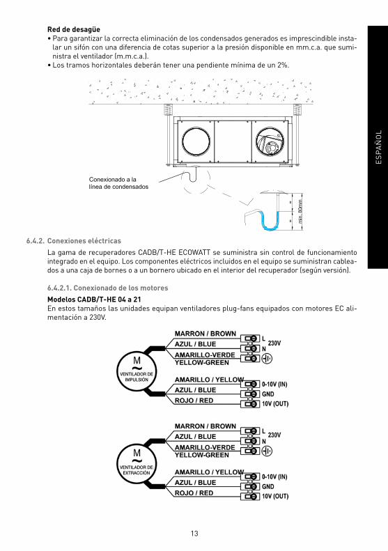
Red de desagüe
• Para garantizar la correcta eliminación de los condensados generados es imprescindible insta-
lar un sifón con una diferencia de cotas superior a la presión disponible en mm.c.a. que sumi-
nistra el ventilador (m.m.c.a.).
• Los tramos horizontales deberán tener una pendiente mínima de un 2%.
6.4.2. Conexiones eléctricas
La gama de recuperadores CADB/T-HE ECOWATT se suministra sin control de funcionamiento
integrado en el equipo. Los componentes eléctricos incluidos en el equipo se suministran cablea-
dos a una caja de bornes o a un bornero ubicado en el interior del recuperador (según versión).
6.4.2.1. Conexionado de los motores
Modelos CADB/T-HE 04 a 21
En estos tamaños las unidades equipan ventiladores plug-fans equipados con motores EC ali-
mentación a 230V.
VENTILADOR DEEXTRACCIÓN
VENTILADOR DEIMPULSIÓN

14
ES
PA
ÑO
L
Modelos CADB/T-HE 40 a 54
Los modelos de los tamaños 40 a 54 equipan motores trifásicos AC alimentados a 230V a través
de variador de frecuencia incluido integrado en el equipo y cableado.
230V/1Ph/50Hz
230/400V
230/400V
L1: Paro/ MarchaL2: Motor de alarma
L1: Paro/ MarchaL2: Motor de alarma
INTERRUPTOR PRINCIPAL
Motor de impulsión
Motor de impulsión
CONVERTIDORDE FRECUENCIA
CONVERTIDORDE FRECUENCIA
6.4.2.2. Conexión del by-pass
Todos los recuperadores de la gama CADB/T-HE ECOWATT incorporan by-pass interno. La
compuerta de by-pass se suministra con su correspondiente actuador montado (alimentación
230V) y cableado a caja de una caja bornes o bornero interno (según versión).
Mediante el accesorio FC-REG es posible realizar el control del by-pass en modo free-cooling.

15
ES
PA
ÑO
L
6.4.2.3. Conexión de las resistencias eléctricas
Las versiones CADB/T-HE-DI se suministran con baterías eléctricas de postcalefacción monta-
das en el interior del equipo.
PELIGRO DE INCENDIO
Para realizar el control de la potencia calefactora de la resistencia eléctrica es necesario que el
instalador eléctrico realice la correspondiente maniobra eléctrica de control.
El instalador es responsable del correcto funcionamiento de la maniobra eléctrica, en especial de
que ésta, disponga de todos los requisitos de seguridad que eviten el riesgo de sobre temperatura
en el interior del equipo.
Esquemas de maniobra recomendados

16
ES
PA
ÑO
L
Las baterías eléctricas disponen de dos protectores térmicos de rearme automático y rearme
manual. Se trata de dispositivos de seguridad que deben utilizarse exclusivamente como ele-
mentos de seguridad, y en ningún caso pueden considerarse termostatos de regulación de la
potencia de las resistencias.
En caso de producirse la actuación de un protector térmico de rearme manual, antes de rear-
marlo, asegurarse que han sido localizadas las causar que produjeron su activación y han sido
solucionadas.
Ubicación de los protectores térmicos
Modelos horizontales: Modelos verticales:
Peligro de quemaduras, existe riesgo que las partes metálicas se encuentren a alta
temperatura.

17
ES
PA
ÑO
L
6.4.2.4. Conexión de accesorios eléctricos
Mediante los accesorios existentes es posible realizar el control de los ventiladores en modo
VAV, COP, CAV.
Elementos de control necesarios para regular la velocidad de los ventiladores
(Válidos para versiones -D, -DC, -DI)
Modelo Accesorios para el
Sistema Volumen Aire Variable por CO2
Accesorios
para el funcionamiento
a presión Constante
Accesorios
para el control manual
de la velocidad
Variador Sensor Variador Sonda Regulador
electrónico
Variador de
frecuencia
CADB-HE D/DI/DC 04 CONTROL AERO-REG
SCO2-A (0-10V)
SCO2-AD (0-10V)
SCO2-G (0-10V)
CONTROL AERO-REG** TDP-D* REB-ECOWATT** -
CADB-HE D/DI/DC 08 CONTROL AERO-REG CONTROL AERO-REG** TDP-D* REB-ECOWATT** -
CADB-HE D/DI/DC 16 CONTROL AERO-REG CONTROL AERO-REG** TDP-D* REB-ECOWATT** -
CADB/T-HE D/DI/DC 21 CONTROL AERO-REG CONTROL AERO-REG** TDP-D* REB-ECOWATT** -
CADB/T-HE D/DI/DC 40 INCLUÍDO INCLUÍDO TDP-D* - INCLUÍDO
CADB/T-HE D/DI/DC 54 INCLUÍDO INCLUÍDO TDP-D* - INCLUÍDO
* Para el control independiente del punto de trabajo de cada circuito, el ventilador de impulsión y el de extracción deben ser
controlados por dos sondas de presión.
** Para el control independiente del punto de trabajo de cada circuito, el ventilador de impulsión y el de extracción deben
ser controlados con su correspondiente regulador electrónico.
6.4.2.4.1. Control VAV (Caudal variable), ajuste manual
Es posible realizar el control en modo VAV de forma manual mediante potenciómetro o de forma
automática en función del valor medido por un sensor externo de calidad de aire (CO2), tempe-
ratura o humedad.
Control manual mediante potenciómetro externo REB-ECOWATT (accesorio). Válido para mo-
delos CADB/T-HE 04 a 21.

18
ES
PA
ÑO
L
Control manual mediante potenciómetro integrado en los variadores de frecuencia ubicados
en el interior del equipo. Válido para los modelos CADB/T-HE 40 and 54.
1. Retirar el panel que da acceso
a los variadores de frecuencia.
2. Modifi car la frecuencia de alimentación
del variador mediante giro del potenciómetro
existente en el frontal del variador.
Potenciómetro externo
6.4.2.4.2. Control VAV (Caudal variable), mediante sensor de CO2 o similar
Modelos 04 a 21:
Equipan motores EC alimentados a 230V, en los que existen unos bornes específi cos para el
envío de una señal de regulación de velocidad del motor (0-10V)
La señal de 0V corresponde al paro del ventilador, mientras que la señal de 10V corresponde a
la velocidad máxima del ventilador.
Para realizar la regulación de velocidad en VAV con control de la velocidad mediante sonda
externa de CO2 o similar, es necesario utilizar el accesorio CONTROL AERO-REG y el correspon-

19
ES
PA
ÑO
L
diente sensor externo (ver punto 6.5.2.4.). En las instrucciones del accesorio CONTROL AERO-
REG encontrará la información detallada para realizar el conexionado eléctrico de los distintos
componentes.
Modelos 40 y 54:
Equipan dos variadores de frecuencia, mediante los que es posible realizar la regulación de los
motores en función del valor de un sensor de CO2.
Siga los siguientes puntos para realizar el ajuste de los parámetros de funcionamiento de cada
variador:
Reconfi guración del variador
Los convertidores de frecuencia vienen pre-programados para utilizarse sea en control propor-
cional con el potenciómetro integrado (FR2 con puente entre 24V y LI3), sea para utilizarse en
control PI con entrada de tensión 0-10V (FR1 con puente entre 24V y LI1).
Para conseguir otras aplicaciones es necesario reprogramar alguno de los parámetros que vie-
nen confi gurados en el variador de frecuencia. Para ello, deberá utilizar los siguientes mandos
del variador:
Paso 1. Desbloquear el convertidor
Para desbloquear el convertidor debemos introducir la contraseña. Para ello debemos realizar
la siguiente
secuencia:
- Pulsar ESC hasta que aparezca “rdy” en pantalla.
- Pulsar ENTER y girar la rueda en sentido negativo hasta que aparezca “SUP-” en pantalla.
- Pulsar ENTER y girar la rueda en sentido positivo hasta que aparezca “COd-” en pantalla.
- Pulsar ENTER y girar la rueda en sentido positivo hasta que aparezca “1951” en pantalla.
- El código introducido parpadeará. En este momento el variador se encuentra desprotegido.
Paso 2. Entrar en modo programación
El variador dispone de 2 MODOS de funcionamiento, RUN y PROGRAMACION, para pasar de
uno al otro es necesario pulsar ESC durante dos segundos.
- Pulsar ESC durante 2 segundos hasta que los 3 leds indicadores de modo se iluminen de for-
ma simultánea. En estos momentos se encuentra en el Modo Programación.
Entrar los parámetros en función de la aplicación requerida.

20
ES
PA
ÑO
L
Control proporcional automático con señal 0-10V de una sonda analógica externa
(CO2, temperatura o humedad relativa)
Características
En esta aplicación el equipo se utiliza para regular el caudal de aire en función del valor medido
por una sonda externa.
Es posible modifi car el comportamiento de la respuesta proporcional modifi cando el valor de
los parámetros LSP, HSP, CrL3 y CRH3.
Para realizar esta aplicación es necesario reprogramar alguno de los parámetros que vienen
confi gurados en el variador de frecuencia. Para ello es necesario desproteger el variador y ac-
ceder al modo programación (pasos 1 y 2 del punto 2.2.) y posteriormente realizar las siguientes
modifi caciones en la confi guración:
- Pulsar ENTER y girar la rueda en sentido negativo hasta que aparezca “SEt-” en pantalla.
- Pulsar ENTER y girar la rueda en sentido negativo hasta que aparezca “LSP” en pantalla.
- Pulsar ENTER y girar la rueda hasta obtener el valor deseado para el parámetro “Frecuencia
mínima en Hz”.
- Pulsar ENTER para confi rmar el valor introducido. Si se trata de un valor distinto al existente
previamente, el display debe parpadear.
- Pulsar ESC para salir del parámetro “LSP”.
- Girar la rueda hasta que aparezca ”HSP” en pantalla
- Pulsar ENTER y girar la rueda hasta obtener el valor deseado para el parámetro “Frecuencia
máxima en Hz”. Pulsar ENTER para confi rmar el valor introducido. Si se trata de un valor
distinto al existente previamente, el display debe parpadear.
- Pulsar ESC para salir del parámetro “HSP”.
- Pulsar ESC para salir del menú “Set-”.
- Seguir la metodología utilizada para confi gurar los dos parámetros iniciales, hasta que se
hayan confi gurado todos los parámetros de la siguiente tabla:
Menú Parámetro Valor Comentario
I_O- CrL3 7.2 Valor mínimo de referencia (mA)
I_O- CrH3 14.4 Valor máximo de referencia (mA)
Ctl- Fr2 AI3 Referencia de tipo de corriente (mA)
Fun- PI- PIF No Deshabilitar la función PI
- Pulsar ESC para salir del menú “Ctl-”.
- Pulsar ESC durante 2 segundos hasta que los 3 leds indicadores de modo se iluminen de
forma secuencial. En estos momentos se encuentra en el modo RUN, disponible para el fun-
cionamiento automático del variador.

21
ES
PA
ÑO
L
Esquema de conexiones
CONVERTIDOR DE FRECUENCIA
CONVERTIDOR DE FRECUENCIA
Motor de impulsión
Motor de impulsión
* Resistencias suministradas en el interior del armario eléctrico.
6.4.2.4.3. Control CAV (Caudal constante)
El variador se utiliza para garantizar un determinado caudal de aire en una red de conductos,
independientemente del estado de ensuciamiento de los fi ltros existentes.
Modelos 04 a 21:
Los modelos 04 a 21 equipan motores EC alimentados a 230V, en los que existen unos bornes
específi cos para el envío de una señal de regulación de velocidad del motor (0-10V).
La señal de 0V corresponde al paro del ventilador, mientras que la señal de 10V corresponde a
la velocidad máxima del ventilador.
Para realizar la regulación de velocidad en modo presión o caudal constante, es necesario utili-
zar el accesorio CONTROL AERO-REG y el correspondiente sensor externo TDP-D.
1º Conecte los transmisores de presión TDP-D (accesorio) en las tomas de presión existentes
en el recuperador, asegurándose que las tomas “+” y “–“ del transmisor de presión coinciden
con las del recuperador:
22
ES
PA
ÑO
L
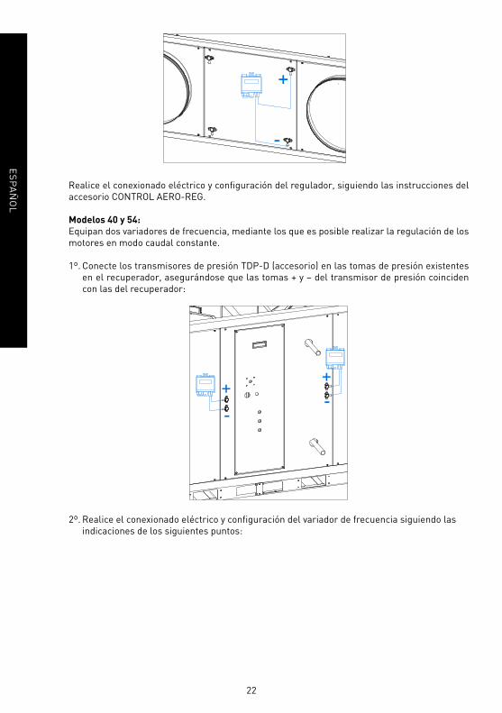
Realice el conexionado eléctrico y confi guración del regulador, siguiendo las instrucciones del
accesorio CONTROL AERO-REG.
Modelos 40 y 54:
Equipan dos variadores de frecuencia, mediante los que es posible realizar la regulación de los
motores en modo caudal constante.
1º. Conecte los transmisores de presión TDP-D (accesorio) en las tomas de presión existentes
en el recuperador, asegurándose que las tomas + y – del transmisor de presión coinciden
con las del recuperador:
2º. Realice el conexionado eléctrico y confi guración del variador de frecuencia siguiendo las
indicaciones de los siguientes puntos:

23
ES
PA
ÑO
L
CONVERTIDOR DE FRECUENCIA
Motor de impulsión
Reconfi guración del variador
Los convertidores de frecuencia vienen pre-programados para utilizarse sea en control propor-
cional con el potenciómetro integrado (FR2 con puente entre 24V y LI3), sea para utilizarse en
control PI con entrada de tensión 0-10V (FR1 con puente entre 24V y LI1).
Para conseguir otras aplicaciones es necesario reprogramar alguno de los parámetros que vie-
nen confi gurados en el variador de frecuencia. Para ello, deberá utilizar los siguientes mandos
del variador:
Paso 1. Desbloquear el convertidor
Para desbloquear el convertidor debemos introducir la contraseña. Para ello debemos realizar
la siguiente
secuencia:
- Pulsar ESC hasta que aparezca “rdy” en pantalla.
- Pulsar ENTER y girar la rueda en sentido negativo hasta que aparezca “SUP-” en pantalla.
- Pulsar ENTER y girar la rueda en sentido positivo hasta que aparezca “COd-” en pantalla.
- Pulsar ENTER y girar la rueda en sentido positivo hasta que aparezca “1951” en pantalla.
- El código introducido parpadeará. En este momento el variador se encuentra desprotegido.
Paso 2. Entrar en modo programación
El variador dispone de 2 MODOS de funcionamiento, RUN y PROGRAMACION, para pasar de
uno al otro es necesario pulsar ESC durante dos segundos.
24
ES
PA
ÑO
L
- Pulsar ESC durante 2 segundos hasta que los 3 leds indicadores de modo se iluminen de for-
ma simultánea. En estos momentos se encuentra en el Modo Programación.
Entrar los parámetros en función de la aplicación requerida.
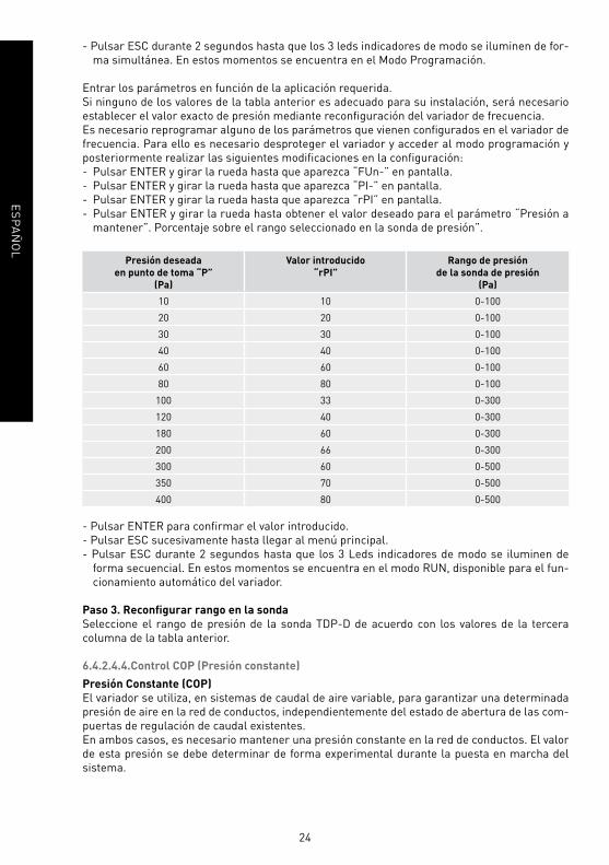
Si ninguno de los valores de la tabla anterior es adecuado para su instalación, será necesario
establecer el valor exacto de presión mediante reconfi guración del variador de frecuencia.
Es necesario reprogramar alguno de los parámetros que vienen confi gurados en el variador de
frecuencia. Para ello es necesario desproteger el variador y acceder al modo programación y
posteriormente realizar las siguientes modifi caciones en la confi guración:
- Pulsar ENTER y girar la rueda hasta que aparezca “FUn-” en pantalla.
- Pulsar ENTER y girar la rueda hasta que aparezca “PI-” en pantalla.
- Pulsar ENTER y girar la rueda hasta que aparezca “rPI” en pantalla.
- Pulsar ENTER y girar la rueda hasta obtener el valor deseado para el parámetro “Presión a
mantener”. Porcentaje sobre el rango seleccionado en la sonda de presión”.
Presión deseada
en punto de toma “P”
(Pa)
Valor introducido
“rPI”
Rango de presión
de la sonda de presión
(Pa)
10 10 0-100
20 20 0-100
30 30 0-100
40 40 0-100
60 60 0-100
80 80 0-100
100 33 0-300
120 40 0-300
180 60 0-300
200 66 0-300
300 60 0-500
350 70 0-500
400 80 0-500
- Pulsar ENTER para confi rmar el valor introducido.
- Pulsar ESC sucesivamente hasta llegar al menú principal.
- Pulsar ESC durante 2 segundos hasta que los 3 Leds indicadores de modo se iluminen de
forma secuencial. En estos momentos se encuentra en el modo RUN, disponible para el fun-
cionamiento automático del variador.
Paso 3. Reconfi gurar rango en la sonda
Seleccione el rango de presión de la sonda TDP-D de acuerdo con los valores de la tercera
columna de la tabla anterior.
6.4.2.4.4.Control COP (Presión constante)
Presión Constante (COP)
El variador se utiliza, en sistemas de caudal de aire variable, para garantizar una determinada
presión de aire en la red de conductos, independientemente del estado de abertura de las com-
puertas de regulación de caudal existentes.
En ambos casos, es necesario mantener una presión constante en la red de conductos. El valor
de esta presión se debe determinar de forma experimental durante la puesta en marcha del
sistema.

25
ES
PA
ÑO
L
Modelos 04 a 21:
Equipan motores EC alimentados a 230V, en los que existen unos bornes específi cos para el
envío de una señal de regulación de velocidad del motor (0-10V).
La señal de 0V corresponde al paro del ventilador, mientras que la señal de 10V corresponde a
la velocidad máxima del ventilador.
Para realizar la regulación de velocidad en modo presión constante, es necesario utilizar el
accesorio CONTROL AERO-REG y el correspondiente sensor externo TDP-D.
1º Conecte los transmisores de presión TDP-D (accesorio) en las tomas de presión existentes
en el recuperador, asegurándose que las tomas “+” y “–“del transmisor de presión coinciden
con las del recuperador:
Realice el conexionado eléctrico y confi guración del regulador, siguiendo las instrucciones
del accesorio CONTROL AERO-REG.
26
ES
PA
ÑO
L
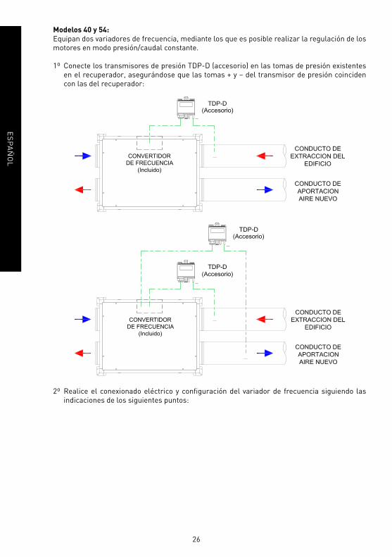
Modelos 40 y 54:
Equipan dos variadores de frecuencia, mediante los que es posible realizar la regulación de los
motores en modo presión/caudal constante.
1º Conecte los transmisores de presión TDP-D (accesorio) en las tomas de presión existentes
en el recuperador, asegurándose que las tomas + y – del transmisor de presión coinciden
con las del recuperador:
2º Realice el conexionado eléctrico y confi guración del variador de frecuencia siguiendo las
indicaciones de los siguientes puntos:

27
ES
PA
ÑO
L
CONVERTIDOR DE FRECUENCIA
CONVERTIDOR DE FRECUENCIA
Motor de impulsión
Motor de impulsión
CONVERTIDOR DE FRECUENCIA
Motor de impulsión

28
ES
PA
ÑO
L
Para ajustar la presión de trabajo deseada, en primer lugar se intentará realizar el ajuste me-
diante modifi cación del rango de la sonda. Los valores establecidos de presión serán los si-
guientes:
Valor introducido
“rPI”
Presión a mantener
en red de conductos
(Pa)
0-100 50
0-150 75
0-300 150
0-500 250
0-1000 500
Si ninguno de los valores de la tabla anterior es adecuado para su instalación, será necesario
establecer el valor exacto de presión mediante reconfi guración del variador de frecuencia.
Presión deseada
en punto de toma “P”
(Pa)
Valor introducido
“rPI”
Rango de presión
de la sonda de presión
(Pa)
10 10 0-100
20 20 0-100
30 30 0-100
40 40 0-100
60 60 0-100
80 80 0-100
100 33 0-300
120 40 0-300
180 60 0-300
200 66 0-300
300 60 0-500
350 70 0-500
400 80 0-500
3º Reconfi gurar rango en la sonda
Seleccione el rango de presión de la sonda TPD de acuerdo con los valores de la tercera
columna de la tabla anterior.
29
ES
PA
ÑO
L
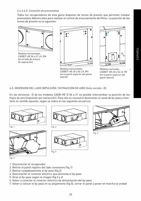
6.4.2.4.5. Conexión de presostatos
Todos los recuperadores de esta gama disponen de tomas de presión que permiten instalar
presostatos diferenciales para realizar el control de ensuciamiento de fi ltros. La posición de las
tomas de presión es la siguiente:
Modelos horizontales
CADB/T-HE 04 a 21 LH, RH
(en el lado de la boca
de aspiración)
Modelos horizontales CADB/T-HE 40 a 54 LH, RH(en la parte superior del panel lateral)
Modelos verticales
CADB/T-HE 40 a 54 LV, RV
(en la parte superior del
panel lateral)
6.5. INVERSION DEL LADO IMPULSIÓN / EXTRACCIÓN DE AIRE (Solo versión –D)
En las versiones –D de los modelos CADB-HE-D 04 a 21 es posible intercambiar la posición de los
fl ujos de aire (impulsión por extracción). Para ello es necesario desmontar el canal de by-pass y mon-
tarlo en sentido opuesto, según se indica en las siguiente secuencia:
Fig. 1 Fig. 2
Fig. 3
Fig. 5
Fig. 4
1. Desconectar el recuperador
2. Retirar el panel registro del lado conexiones (fi g.1)
3. Retirar cuidadosamente el by-pass (fi g.2)
4. Desconectar el conector eléctrico que alimenta el by-pass
5. Girar el by-pass según la imagen (fi g.3 y 4)
6. Volver a conectar el conector eléctrico de alimentación del by-pass
7. Volver a colocar el by-pass en su alojamiento (fi g.5), cerrar el panel y poner en marcha la unidad
30
ES
PA
ÑO
L
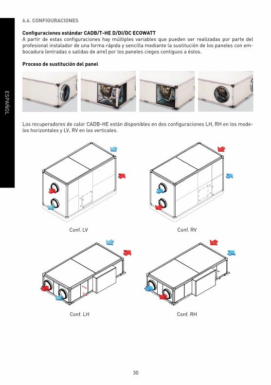
6.6. CONFIGURACIONES
Confi guraciones estándar CADB/T-HE D/DI/DC ECOWATT
A partir de estas configuraciones hay múltiples variables que pueden ser realizadas por parte del
profesional instalador de una forma rápida y sencilla mediante la sustitución de los paneles con em-
bocadura (entradas o salidas de aire) por los paneles ciegos contiguos a éstos.
Proceso de sustitución del panel
Los recuperadores de calor CADB-HE están disponibles en dos confi guraciones LH, RH en los mode-
los horizontales y LV, RV en los verticales.
Conf. LV
Conf. LH
Conf. RV
Conf. RH
31
ES
PA
ÑO
L
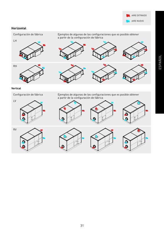
Vertical
Horizontal
Confi guración de fábrica
LH
RH
Ejemplos de algunas de las confi guraciones que es posible obtener a partir de la confi guración de fábrica
Confi guración de fábrica
LV
Ejemplos de algunas de las confi guraciones que es posible obtener a partir de la confi guración de fábrica
RV
AIRE EXTRAIDO
AIRE NUEVO

32
ES
PA
ÑO
L
7. INSPECCIÓN, MANTENIMIENTO Y LIMPIEZA
7.1. SUSTITUCIÓN DE FILTROS
La ubicación de los registros para mantenimiento de fi ltros dependen del modelo y versión. La ubica-
ción exacta de los fi ltros queda identifi cada con una etiqueta en el perfi l indicando las características
del fi ltro instalado.
CAIDA DE OBJETOS
Al afl ojar los tornillos que sujetan los paneles, éstos quedarán liberados. En equipos
instalados en techo, prestar especial atención a esta operación para evitar la caída del
panel. Durante las tareas de mantenimiento señalizar la zona de debajo del recuperador
e impedir el acceso de personal a la misma.
• Confi guraciones horizontales del modelo CADB/T-HE 04 a 21. El acceso a fi ltros se puede realizar
desde las paredes laterales y/o interiores:
Acceso rápido a fi ltros desde los paneles laterales.
Acceso rápido a fi ltros desde los paneles inferiores.
• Confi guraciones horizontales del modelo CADB/T-HE 40 y 54. El acceso a fi ltros se puede realizar
por el lateral del equipo:
• Confi guraciones verticales del modelo CADB/T-HE 40 y 54. El acceso a fi ltros se puede realizar por
ambos lados del equipo, desmontando los paneles específi cos según imagen:

33
ES
PA
ÑO
L
Los fi ltros de recambio se entregan en una bolsa de plástico para mayor protección. Retirar la bolsa
antes de poner en marcha el equipo.
Antes de montar el fi ltro asegurarse de que el sentido del fl ujo de aire es el correcto. (Indicado mediante
fl echa en el marco del fi ltro).
Tabla de recambios de fi ltros
Modelo
Recuperador
Ø
(mm)
AFR-HE (Filtros accesorio y recambio para CADB/T-HE)
AFR-HE G4 AFR-HE M5 AFR-HE F7 AFR-HE F9
CADB-HE D/DI/DC 04 200 AFR-HE 200/04 G4 AFR-HE 200/04 M5 AFR-HE 200/04 F7 AFR-HE 200/04 F9
CADB-HE D/DI/DC 08 250 AFR-HE 250/08 G4 AFR-HE 250/08 M5 AFR-HE 250/08 F7 AFR-HE 250/08 F9
CADB-HE D/DI/DC 16 315 AFR-HE 315/16 G4 AFR-HE 315/16 M5 AFR-HE 315/16 F7 AFR-HE 315/16 F9
CADB/T-HE D/DI/DC 21 400 AFR-HE 400/21 G4 AFR-HE 400/21 M5 AFR-HE 400/21 F7 AFR-HE 400/21 F9
CADB/T-HE D/DI/DC 40 450 AFR-HE 450/40 G4 AFR-HE 450/40 M5 AFR-HE 450/40 F7 AFR-HE 450/40 F9
CADB/T-HE D/DI/DC 54 500 AFR-HE 500/54 G4 AFR-HE 500/54 M5 AFR-HE 500/54 F7 AFR-HE 500/54 F9
7.2. MONTAJE FILTROS
El recuperador se suministra con los fi ltros ya montados.
F7 en el sentido de aportación de aire nuevo y M5 en el sentido de extracción de aire viciado.
Adicionalmente, es posible montar un segundo fi ltro en el equipo (suministro como accesorio).
Proceso de montaje del fi ltro adicional:
1. Afl ojar las palometas que sujetan los dos soportes
porta-fi ltros.
2. Retirar los soportes porta-fi ltros.
3. Instalar el segundo fi ltro en su ubicación. Asegurarse
que el sentido del aire sea el correcto (indicado me-
diante una fl echa en el marco del fi ltro).
4. Asegurarse que el primer fi ltro en el orden de paso del
aire sea el de menor grado de fi ltración.
5. Una vez introducidos ambos fi ltros colocar los sopor-
tes portafi ltros de forma simétrica a la que se realiza
cuando el montaje es de un solo fi ltro y realizar apriete
con las 4 palometas.

34
ES
PA
ÑO
L
7.3. INTERCAMBIADOR DE CALOR
Modelos horizontales CADB/T-HE 04 a 21
Para realizar la limpieza del intercambiador de calor es necesario desmontarlo del equipo.
El desmontaje puede realizarse fácilmente desde el panel lateral:
Secuencia desmontaje core por lateral
Modelos 04 a 21: Acceso para la limpieza del intercambiador desde los paneles laterales e inferiores.
Necesidad de desmontaje del intercambiador.
Modelos 40 y 54: Acceso para la limpieza del intercambiador desde los paneles laterales.
Alternativamente también es posible realizar el desmontaje del intercambiador de calor desde los
paneles inferiores, si bien en este caso es necesario realizar un mayor número de operaciones para
proceder a su desmontaje.
Secuencia acceso al intercambiador de calor por debajo
CAIDA DE OBJETOS
Al afl ojar los tornillos que sujetan los paneles, éstos quedarán liberados. En equipos
instalados en techo, prestar especial atención a esta operación para evitar la caída del
panel y del intercambiador de calor. Durante las tareas de mantenimiento señalizar la
zona de debajo del recuperador e impedir el acceso de personal a la misma.
PNo manipular el intercambiador por la zona aleteada.

35
ES
PA
ÑO
L
Modelos horizontales CADB/T-HE 40 y 54
Debido a las dimensiones y peso del intercambiador de calor, la limpieza de éste debe ser realizada in
situ, sin que sea posible desmontar el intercambiador de calor.
Para acceder al intercambiador, desmontar los paneles laterales del recuperador y proceder a la
limpieza de éste mediante soplado con pistola de aire comprimido.
Afl ojar los 4 cierres rápidos que fi jan
el panel de acceso a fi ltros y retirar
el panel.
Afl ojar los tornillos que sujetan el fi ltro
y una vez liberado, extraerlo. Limpiar el
intercambiador mediante soplado con
con pistola de aire comprimido.
Modelos verticales CADB/T-HE 40 y 54
Debido a las dimensiones y peso del intercambiador de calor, la limpieza de éste debe ser realizada in
situ, sin que sea posible desmontar el intercambiador de calor.
Para acceder al intercambiador, desmontar los paneles laterales y superiores del recuperador y pro-
ceder a la limpieza de éste mediante soplado con pistola de aire comprimido.
7.4. TUBO DE DESAGÜE DE CONDENSADOS
Inspeccione periódicamente el tubo de desagüe de condensados, para evitar que quede atascado y, en
ese caso, retire los restos que lo atasquen.
Comprobar que la tubería de desagüe ha sido realizada de acuerdo con las indicaciones del apartado
“CONEXIONES” de este manual.

36
ES
PA
ÑO
L
8. ANOMALÍAS DE FUNCIONAMIENTO
8.1. ANOMALÍAS GENERALES
Anomalía Causa Solución
Arranque difícil. Tensión de alimentación reducida.
Par estático del motor
insufi ciente.
Verifi car datos de placa del motor.
Cerrar las entradas de aire para alcanzar la
máxima velocidad.
Si es necesario, cambie el motor.
Contacte con el Servicio Postventa de S&P.
Caudal de aire
insufi ciente.
Presión insufi ciente.
Tuberías atascadas y/o puntos de
aspiración cerrados.
Ventilador obstruido.
Filtro sobrecargado.
Velocidad de rotación insufi ciente.
Paquete intercambiador obturado.
Limpieza de los tubos de aspiración.
Limpieza del ventilador.
Limpiar o sustituir el fi ltro.
Verifi car la tensión de alimentación.
Limpieza del intercambiador.
Caída de rendimiento
después de un periodo
de funcionamiento
aceptable.
Fuga en el circuito antes y/o
después del ventilador.
Rodete dañado.
Verifi cación del circuito y restauración de las
condiciones originales.
Verifi car el rodete y en caso necesario,
sustituirlo con un recambio original.
Contacte con el Servicio Postventa de S&P.
Temperatura aire nuevo
demasiado baja.
Aire exterior inferior a -5ºC.
Modelos (CADB/T-DI): Protectores
térmicos.
Resistencias de Apoyo abiertos.
Inserción dispositivos de postcalentamiento.
Contacte con el Servicio Postventa de S&P.
Rearme mediante el pulsador RESET, todos los
protectores térmicos de la resistencia.
Rendimiento insufi ciente
del intercambiador.
Aletas intercambio sucias. Limpieza del intercambiador.
Formación de escarcha
en el intercambiador.
Aire exterior inferior a -5ºC. Inserción de dispositivos de precalentamiento
(anti-hielo).
Contacte con el Servicio de Asesorías de S&P.
Pulsación de aire. Ventilador que trabaja en
condiciones de caudal
excesivamente baja.
Inestabilidad de fl ujo, obstrucción
o mala conexión.
Modifi cación del circuito y/o sustitución del
ventilador.
Limpieza y/o reajuste canales de aspiración.
Intervenir en el regulador electrónico aumentando
la velocidad mínima (voltaje insufi ciente).
Contacte con el Servicio de Asesorías de S&P.
Agua en el interior del
equipo.
Desagüe obstruido o mal
dimensionado.
Verifi car si existe algún cuerpo/objeto que
obstruya el paso del agua, y retírelo. Verifi car que
existe y que éste está dimensionado según las
instrucciones de este manual.
Solo versiones DC. Rotura interna
de la batería de agua.
Aislar la bateria mediante las válvulas de
aislamiento. Reparar la fuga/sustituir la bateria.
Solo versiones DC. La bateria
de agua se está utilizando para
refrigeración con agua fría.
Los recuperadores CADB-HE DC son válidos para
post-calefacción con agua caliente.

37
EN
GL
ISH
INDEX
1. INTRODUCTION ........................................................................................................................................................38
2. SAFETY REGULATIONS AND “CE” MARKING ..........................................................................................................38
3. GENERAL INSTRUCTIONS .......................................................................................................................................38
4. UNIT LABELLING .....................................................................................................................................................38
5. HANDLING ................................................................................................................................................................39
6. INSTALLATION ..........................................................................................................................................................40
6.1. Introduction........................................................................................................................................................40
6.1.1. Outdoor installation .................................................................................................................................43
6.2. Dimensions and free space for maintenance ...................................................................................................44
6.3. Range specifi cations ..........................................................................................................................................46
6.4. Connections .......................................................................................................................................................46
6.4.1. Piping and duct connections ...................................................................................................................46
6.4.1.1. Connection with air duct ............................................................................................................46
6.4.1.2. Connecting the water coil piping. DC versions ..........................................................................47
6.4.1.3. Condensate drainage .................................................................................................................47
6.4.2. Electrical connection ...............................................................................................................................48
6.4.2.1. Connecting the motors ...............................................................................................................48
6.4.2.2. Connecting the By-pass .............................................................................................................49
6.4.2.3. Connecting the electric batteries ...............................................................................................49
6.4.2.4. Connecting electrical accessories .............................................................................................52
6.4.2.4.1. Manual VAV control (variable airfl ow) ........................................................................52
6.4.2.4.2. VAV Control (variable airfl ow), with CO2 sensor or similar ........................................52
6.4.2.4.3. CAV control (Constant airfl ow)....................................................................................56
6.4.2.4.4. COP Control (Constant pressure) ...............................................................................59
6.4.2.4.5. Pressure switch connection .......................................................................................64
6.5. Reverse supply air/extract air side (only -D version) ........................................................................................64
6.6. Confi gurations ...................................................................................................................................................65
7. INSPECTION, MAINTENANCE AND CLEANING .........................................................................................................67
7.1. Filters .................................................................................................................................................................67
7.2. Filter installation ...............................................................................................................................................68
7.3. Heat exchanger ..................................................................................................................................................69
7.4. Condensation drainpipe .....................................................................................................................................70
8. OPERATION ANOMALIES .........................................................................................................................................71
8.1. General anomalies ............................................................................................................................................71
ENGLISH
38
EN
GL
ISH
1. INTRODUCTION
Thank you for purchasing this appliance. It has been manufactured in full compliance with applicable
safety regulations and EU standards.
Please read this instruction book carefully, as it contains important information for your safety during
the installation, use and maintenance of this product.
Keep it at hand for future reference.
Please check that the appliance is in perfect condition when you unpack it, as all factory defects are
covered by the S&P guarantee.
2. SAFETY REGULATIONS AND “CE” MARKING
S&P technicians are fi rmly committed to research and development of ever more effi cient products
and in compliance with current safety regulations.
The instructions and recommendations given below refl ect current regulations, principally regarding
safety, and therefore are based on compliance with general regulations. Therefore, we recommend all
people exposed to hazards to strictly follow the safety regulations in force in your country. S&P will not
be held liable for any possible harm or damage caused by non-compliance with the safety regulations,
as well as caused by modifying the product.
The CE mark and the corresponding declaration of conformity are proof of the product’s conformity
with current EU regulations.
3. GENERAL INSTRUCTIONS
A hazard analysis of the product has been carried out as provided in the Machine Directive. This ma-
nual contains information for all personnel exposed to these hazards, with the aim of preventing pos-
sible harm or damage due to faulty handling or maintenance.
All maintenance operations (ordinary and extraordinary) must be carried out with the machine swit-
ched off and the electrical power supply disconnected.
To avoid a possible accidental start up, place a warning notice on the electrical control panel with the
following text:
“Attention: control disconnected for maintenance operations”
Before connecting the power supply cable to the terminal strip, make sure the mains voltage corres-
ponds to the voltage indicated on the specifi cations plate of the unit.
Regularly check the product labels. If, due to the passing of time, they are no longer legible, they must
be replaced.
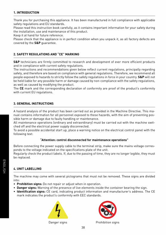
4. UNIT LABELLING
The machine may come with several pictograms that must not be removed. These signs are divided
into:
• Prohibition signs: Do not repair or adjust when in operation.
• Danger signs: Warning of the presence of live elements inside the container bearing the sign.
• Identifi cation signs: CE card, indicating product information and manufacturer’s address. The CE
mark indicates the product’s conformity with EEC standards.
Danger signs Prohibition signs
39
EN
GL
ISH
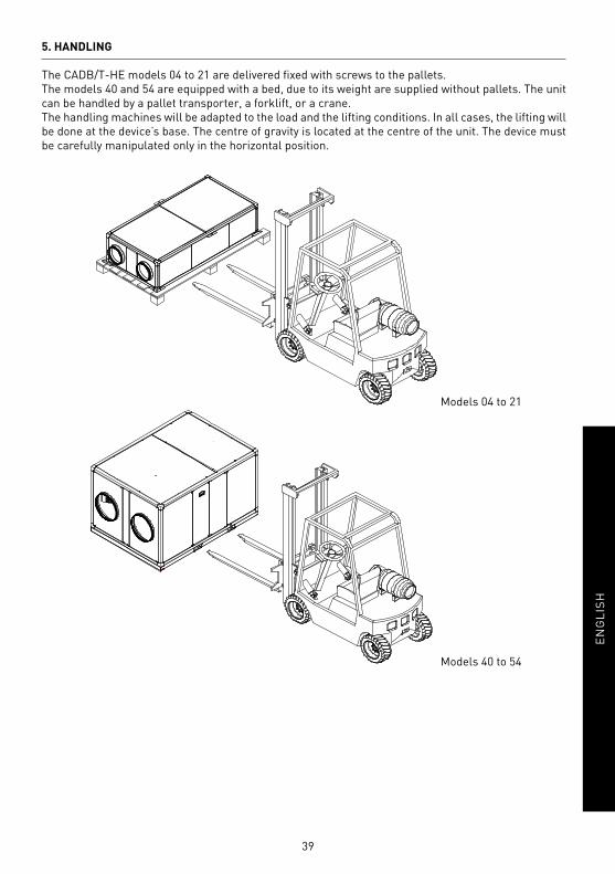
5. HANDLING
The CADB/T-HE models 04 to 21 are delivered fi xed with screws to the pallets.
The models 40 and 54 are equipped with a bed, due to its weight are supplied without pallets. The unit
can be handled by a pallet transporter, a forklift, or a crane.
The handling machines will be adapted to the load and the lifting conditions. In all cases, the lifting will
be done at the device’s base. The centre of gravity is located at the centre of the unit. The device must
be carefully manipulated only in the horizontal position.
Models 04 to 21
Models 40 to 54

40
EN
GL
ISH
6. INSTALLATION
6.1. INTRODUCTION
Horizontal models size 04, 08, 16 and 21
These models are designed to be installed hanging from the ceiling or located behind a false ceiling.
The 04, 08, 16 and 21 models have four metal brackets, one on each lower corner. Using studded rods
(Ø 8 mm), it can be secured to the ceiling and levelled.
The installer must make sure that the ceiling structure and the securing elements can bear the weight
of the device, taking into account that it is a dynamic load.
To prevent the transmission of vibrations from the unit to the rest of the installation, it is necessary
that the installer use specifi c isolation elements, such as antivibration devices in the supports, fl exible
sleeves between the unit and the ducts, and fl exible couplings between the water connections and the
pipelines.
Model Weight (kg)
4 147
8 183
16 235
21 333
Vertical models size 40 and 54
Vertical models size 40 and 54 are supplied with a perimetral bed. This bed must be in contact with the
ground or with a fl at surface. It is essential that the weight of the equipment is distributed between all
points of support to prevent unit deformation.
The installer must make sure that the ceiling structure and the securing elements can bear the
weight of the unit, taking into account that it is a dynamic load.

41
EN
GL
ISH
Model Weight (kg)
40 597
54 730
Horizontal models of sizes 40 and 54
IMPORTANT!Particularities in the installation of horizontal versions LH and RH
For a correct evacuation of condensation generated into the heat exchanger, it is necessary to install
the unit with a minimum slope of 3º to the side where the extraction fan is placed:
SUPPLY FANEXTRACT FAN
Horizontal models size 40 and 54 are supplied with a perimetral bed. This bed must be in contact with
the ground or with a fl at surface. It is essential that the weight of the equipment is distributed between
all points of support to prevent unit deformation.
The installer must make sure that the ceiling structure and the securing elements can bear the
weight of the unit, taking into account that it is a dynamic load.
Model Weight (kg)
40 597
54 730

42
EN
GL
ISH
For all confi gurations
Once secured the device in correct position, the installer have to realise the connection with air duct,
connection to the electric supply, and in the case of versions with water coil, the connection with closed
circuit of hot water coil.
Inside of the unit are supplied the following accessories:
Desagüe (Fig.1)
a)
b)c)
x2 x2 x2 x1
Manual
Drain (Fig.1)
a) Drainpipe
b) Female screw
c) Joint ring Install the two drains as indicated in the following drawing:
a) Horizontal versions of CADB/T HE 04 to 21
b) Horizontal versions of CADB/T HE 40 to 54

43
EN
GL
ISH
c) Vertical versions of CADB/T HE 40 to 54
In these versions, the drainpipe and the siphon are supplied mounted in the unit.
6.1.1. Outdoor installation
The CADB/T-HE ECOWATT range is designed to be mounted indoors. When it is installed
outdoors, it is necessary to place the equipment under a cover which offers enough protection
to prevent rain falling directly to the unit, or install the corresponding roof mounting.
In horizontal version, models 04 to 21, ensure the suffi cient space below the unit, to install a
siphons in the drain pipe.
Drain pipe connexion

44
EN
GL
ISH
6.2. DIMENSIONS AND FREE SPACE FOR MAINTENANCE
a) Horizontal versions of CADB/T HE 04 to 21 (False ceiling installation)
Distances for maintenance in installations with access by the lateral panels
Distances for maintenance in installations with access by the inferior panels
False ceiling installation
Model W H L A B C Ø E F Weight
(kg)
04 760 375 1520 400 400 700 200 350 920 147
08 910 425 1750 450 400 860 250 400 950 183
16 1240 450 1950 600 500 1190 315 400 1150 235
21 1640 550 2300 800 700 1590 400 500 1300 333
Conf. LH
Conf. RH
Access to fi lters and heat exchanger
Access to control panel, motors and coils/
battery connections (DI/DC versions)
Conf. LH
Conf. RH
Access to fi lters and heat exchanger Access to fi lters
Access to control panel, motors and coils/
battery connections (DI/DC versions)Access to heat exchanger

45
EN
GL
ISH
b) Horizontal versions of CADB/T HE 40 and 54 (Ground installation)
Conf. LH
Conf. RH
Ground installation
Model W H L A B Ø Weight
(kg)
40 1500 1200 2100 400 600 450 597
54 1550 1580 2250 400 750 500 730
c) Vertical versions of CADB/T HE 40 and 54 (Ground installation)
Conf. LV
Conf. RV
Model W H L A B Ø Weight
(kg)
40 1120 1580 2100 400 1100 450 597
54 1500 1630 2250 400 1450 500 730
Access to fi lters and heat exchanger
Access to control panel, motors and coils/
battery connections (DI/DC versions)
Access to fi lters and heat exchanger
Access to control panel, motors and coils/
battery connections (DI/DC versions)

46
EN
GL
ISH
6.3. RANGE SPECIFICATIONS
D Models: without heater battery
Model Complete unit Fan Weight (kg)Air connections
diameter (mm)
Nominalairfl ow(m3/h)
Effi ciency*(%)
Electricalsupply
Speed(r.p.m.)
Maximumcurrent
(A)
CADB-HE D 04 ECOWATT 200 400 87 1/230V, 50Hz 3500 0,62 145
CADB-HE D 08 ECOWATT 250 800 86,4 1/230V, 50Hz 2650 1,1 180
CADB-HE D 16 ECOWATT 315 1.600 85,5 1/230V, 50Hz 2845 1,6 231
CADB-HE D 21 ECOWATT 400 2.100 86,7 1/230V, 50Hz 1580 1,9 328
CADB-HE D 40 ECOWATT 450 4.000 86,8 1/230V, 50Hz 2435 3,5 588
CADB-HE D 54 ECOWATT 500 5.400 87,1 1/230V, 50Hz 1945 4,8 718
* Humid effi ciency referring to nominal airfl ow, outdoor conditions (-5ºC / 80% RH) and indoor (20ºC / 50% RH).
DC Models: with built-in hot water coil
Model Complete unit Fan Hot water coil Weight
(kg)Air
connections
diameter
(mm)
Nominal
airfl ow
(m3/h)
Effi ciency*
(%)
Electrical
supply
Speed
(r.p.m.)
Maximum
current
(A)
Heat power
T.water
(kW)
T agua 80/60ºC
Heat power
T.water
(kW)
T agua 50/45ºC
CADB-HE DC 04 ECOWATT 200 400 87 1/230V, 50Hz 3500 0,62 2,7 1,6 147
CADB-HE DC 08 ECOWATT 250 800 86,4 1/230V, 50Hz 2650 1,1 5,1 3,1 183
CADB-HE DC 16 ECOWATT 315 1.600 85,5 1/230V, 50Hz 2845 1,6 8,6 5,3 235
CADB-HE DC 21 ECOWATT 400 2.100 86,7 1/230V, 50Hz 1580 1,9 12,6 7,8 333
CADB-HE DC 40 ECOWATT 450 4.000 86,8 1/230V, 50Hz 2435 3,5 23,9 14,4 597
CADB-HE DC 54 ECOWATT 500 5.400 87,1 1/230V, 50Hz 1945 4,8 32,1 19,5 730
* Humid effi ciency referring to nominal airfl ow, outdoor conditions (-5ºC / 80% RH) and indoor (20ºC / 50% RH).
DI Models: with built-in electric heater battery
Model Complete unit Fan Electric heater battery Weight
(kg)Air
connections
diameter
(mm)
Nominal
airfl ow
(m3/h)
Effi ciency*
(%)
Electrical
supply
Speed
(r.p.m.)
Maximum
current
(A)
Electrical
supply
Power
(kW)
Maximum
current
(A)
CADB-HE DI 04 ECOWATT 200 400 87 1/230V, 50Hz 3500 0,62 1/230V, 50Hz 1 4,5 146
CADB-HE DI 08 ECOWATT 250 800 86,4 1/230V, 50Hz 2650 1,1 1/230V, 50Hz 2 9,1 183
CADB-HE DI 16 ECOWATT 315 1.600 85,5 1/230V, 50Hz 2845 1,6 1/230V, 50Hz 3,5 15,9 235
CADT-HE DI 21 ECOWATT 400 2.100 86,7 1/230V, 50Hz 1580 1,9 3/400V, 50Hz 6 9,1 333
CADT-HE DI 40 ECOWATT 450 4.000 86,8 1/230V, 50Hz 2435 3,5 3/400V, 50Hz 9 13,7 597
CADT-HE DI 54 ECOWATT 500 5.400 87,1 1/230V, 50Hz 1945 4,8 3/400V, 50Hz 12 18,2 730
* Humid effi ciency referring to nominal airfl ow, outdoor conditions (-5ºC / 80% RH) and indoor (20ºC / 50% RH).
6.4. CONNECTIONS
6.4.1. Piping and duct connections
6.4.1.1. Connection with air duct
The fans are always blowing out with regard to the machine. Before making the connection of air
lines, verify existing identifi cation labels in each mouth of the heat recovery units.

47
EN
GL
ISH
Outdoor air
Aire exterior
Aria di rinnovo
Air neur
Aussenluft
Extract air
Aire de extracción
Estrazione dal locale
Air repris
Abluft
Exhaust air
Aire de expulsión
Espulsione all esterno
Air rejeté
Fortluft
Supply air
Aire de impulsión
Inmissione
Air Souffl é
Zuluft
6.4.1.2. Connecting the water coil piping. DC Versions
Connecting the unit to the water network
- Maximum pressure: 31.62 bar
- Maximum temperature: 150°C
• Water coils of DC versions have threaded connec-
tions. Secure the coil manifold with the appropiate
tool when tightening the threads. This will prevent
the force from being transmitted to the manifold,
which can damage it.
• The following table indicate the size and type o thread used on water coils for DC versions:
CADB/T-HE MODEL THREAD
04, 08, 16 and 21 1/2”
40 and 54 1”
• To ensure the installation on a hand, it is essential that the installation includes the following
elements:
- Unit intake pre-fi lter that traps suspended particulate matter.
- Bleed valves should be fi tted at each of the high points in the installation.
- Auto-fi lter valve to keep water in the hydraulic system at all times.
- Pressure to detect the lack of water pressure.
- Shut-off valves must be installed at each connection on the water line to allow the unit to be
isolated if necessary (to clean fi lters, make repairs, replace parts, etc) and avoid the need to
completely drain the water circuit.
- Anti-vibration bellows should be installed at the inlet and outlet from the unit to prevent
the transmission of vibrations that could result in damage to the heat exchanger coil due to
excess stress on the circuits.
Once the installation is performed check that the heating water fl ow is adequate.
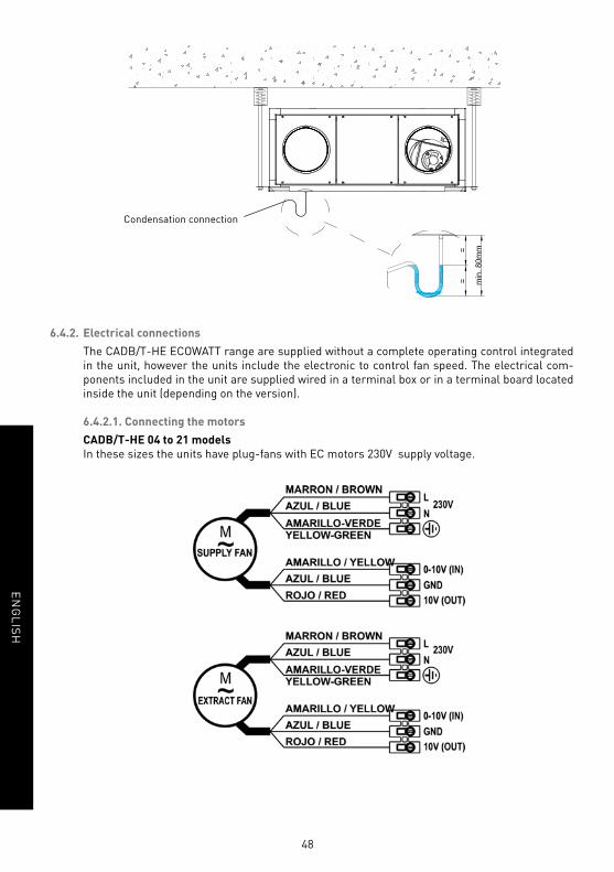
6.4.1.3. Condensate drainage
The units are supplied with 2 drains (one for each circuit). For added security it has to connect
two drains to the condensate discharge pipe. This connection must be made through a pipe of
22 mm of inner diameter and a fl ange for secure fi xation.
Drainage system
• To ensure the removal of draining condensate from the tray a siphon must be installed with
pressure head difference in mmWG greater than the pressure provided by the fan.
• The horizontal sections should have a minimum slope of 2%.
48
EN
GL
ISH
Condensation connection
6.4.2. Electrical connections
The CADB/T-HE ECOWATT range are supplied without a complete operating control integrated
in the unit, however the units include the electronic to control fan speed. The electrical com-
ponents included in the unit are supplied wired in a terminal box or in a terminal board located
inside the unit (depending on the version).
6.4.2.1. Connecting the motors
CADB/T-HE 04 to 21 models
In these sizes the units have plug-fans with EC motors 230V supply voltage.
49
EN
GL
ISH
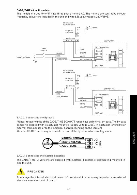
CADB/T-HE 40 to 54 models
The models of sizes 40 to 54 have three phase motors AC. The motors are controlled through
frequency converters included in the unit and wired. (Supply voltage: 230V/3Ph).
230V/1Ph/50Hz
230/400V
230/400V
L1: Stop/StartL2: Alarm motor
L1: Stop/StartL2: Alarm motor
MAINSWITCH
Supply motor
SUPPLY FAN
EXTRACT FAN
L5: “�“ Connection
L5: “�“ Connection
GREY
GREY
BROWN
BROWN
BROWN
BROWN
WHITE
WHITE
BLUE
BLUE
YELLOW/GREEN
YELLOW/GREEN
YELLOW/GREEN
YELLOW/GREEN
Supply motor
FREQUENCY CONVERTER
FREQUENCY CONVERTER
6.4.2.2. Connecting the By-pass
All heat recovery units of the CADB/T-HE ECOWATT range have an internal by-pass. The by-pass
damper is supplied with its actuator mounted (Supply voltage 230V). The actuator is wired to an
external terminal box or to the electrical board (depending on the version)
With the FC-REG accessory is possible to control the by-pass in free-cooling mode.
6.4.2.3. Connecting the electric batteries
The CADB/T-HE-DI versions are supplied with electrical batteries of postheating mounted in-
side the unit.
FIRE DANGER
To manage the internal electrical power (-DI versions) it is necessary to perform an external
electrical operation control board.

50
EN
GL
ISH
The installer is responsible for the correct operation of the electrical control, specially regarding
those safety requirements to avoid fi re risk due to high temperature inside the unit.
Electrical diagrams (Recommended control board)
51
EN
GL
ISH
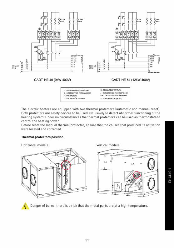
The electric heaters are equipped with two thermal protectors (automatic and manual reset).
Both protectors are safety devices to be used exclusively to detect abnormal functioning of the
heating system. Under no circumstances the thermal protectors can be used as thermostats to
control the heating power.
Before reset the manual thermal protector, ensure that the causes that produced its activation
were located and corrected.
Thermal protectors position
Horizontal models: Vertical models:
Danger of burns, there is a risk that the metal parts are at a high temperature.

52
EN
GL
ISH
6.4.2.4. Connecting electrical accessories
With the existing accessories is possible to perform the fans control in VAV, COP and CAV mode.
Recommended accessories depending on the unit size and the control mode:
Model Accessories for VAV via CO2 Accessories for COP Accessories for CAV
Converter Sensor Converter Probe Electronic
regulator
Frequency
converter
CADB-HE D/DI/DC 04 CONTROL AERO-REG
SCO2-A (0-10V)
SCO2-AD (0-10V)
SCO2-G (0-10V)
CONTROL AERO-REG** TDP-D * REB-ECOWATT** -
CADB-HE D/DI/DC 08 CONTROL AERO-REG CONTROL AERO-REG** TDP-D * REB-ECOWATT** -
CADB-HE D/DI/DC 16 CONTROL AERO-REG CONTROL AERO-REG** TDP-D * REB-ECOWATT** -
CADB/T-HE D/DI/DC 21 CONTROL AERO-REG CONTROL AERO-REG** TDP-D * REB-ECOWATT** -
CADB/T-HE D/DI/DC 40 INCLUDED INCLUDED TDP-D * - INCLUDED
CADB/T-HE D/DI/DC 54 INCLUDED INCLUDED TDP-D * - INCLUDED
* To independently control the workpoint of each circuit, the supply and extract fans should be controlled by two specifi c
pressure probes.
** To independently control the workpoint of each circuit, the supply and extract fans should be controlled via corresponding
electronic regulator.
6.4.2.4.1. Manual VAV control (variable airfl ow)
It is possible to control in VAV mode manually with an external potentiometer
Manual control by external potentiometer REB-ECOWATT (accessory). Valid for CADB/T-HE 04
to 21 models.
Simultaneous control of the supply and extract fans
Supply fanExtract fan

53
EN
GL
ISH
Independent control of supply and extract fans
Supply fanExtract fan
Manual control by the internal potentiometer integrated in the frequency converters located
inside the unit. Valid for CADB/T-HE 40 and 54 models
1. Remove the panel that give access
to the frequency converter.
2. Modify the fan speed (frequency) by means of
the external potentiometer in the frontal of the
frequency converter.
external potentiometer
6.4.2.4.2. VAV Control (variable airfl ow), with CO2 sensor or similar
CADB/T-HE 04 to 21 models:
In these sizes the units have plug-fans with EC motors 230V supply voltage. The motors have
specifi c terminals for sending a regulation signal to control fan speed (0-10V).
The 0V signal corresponds to the fan stop, while the signal of 10V corresponds to fan maximum
speed.
To perform the speed regulation in VAV with speed control with external sensor of CO2 or simi-
lar, it is necessary to use the accessory CONTROL AERO-REG and the external sensor (see point
7.5.2.4.). In the CONTROL AERO-REG instruction booklet it is contained the necessary informa-
tion to carry on the electrical connection of the different components.
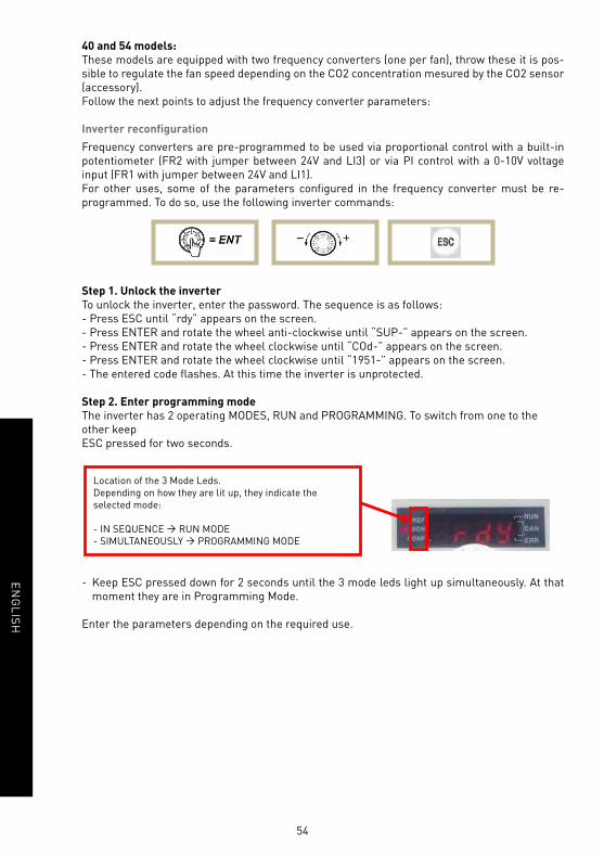
54
EN
GL
ISH
40 and 54 models:
These models are equipped with two frequency converters (one per fan), throw these it is pos-
sible to regulate the fan speed depending on the CO2 concentration mesured by the CO2 sensor
(accessory).
Follow the next points to adjust the frequency converter parameters:
Inverter reconfi guration
Frequency converters are pre-programmed to be used via proportional control with a built-in
potentiometer (FR2 with jumper between 24V and LI3) or via PI control with a 0-10V voltage
input (FR1 with jumper between 24V and LI1).
For other uses, some of the parameters confi gured in the frequency converter must be re-
programmed. To do so, use the following inverter commands:
Step 1. Unlock the inverter
To unlock the inverter, enter the password. The sequence is as follows:
- Press ESC until “rdy” appears on the screen.
- Press ENTER and rotate the wheel anti-clockwise until “SUP-” appears on the screen.
- Press ENTER and rotate the wheel clockwise until “COd-” appears on the screen.
- Press ENTER and rotate the wheel clockwise until “1951-” appears on the screen.
- The entered code fl ashes. At this time the inverter is unprotected.
Step 2. Enter programming mode
The inverter has 2 operating MODES, RUN and PROGRAMMING. To switch from one to the
other keep
ESC pressed for two seconds.
- Keep ESC pressed down for 2 seconds until the 3 mode leds light up simultaneously. At that
moment they are in Programming Mode.
Enter the parameters depending on the required use.
Location of the 3 Mode Leds.
Depending on how they are lit up, they indicate the
selected mode:
- IN SEQUENCE Ò RUN MODE
- SIMULTANEOUSLY Ò PROGRAMMING MODE
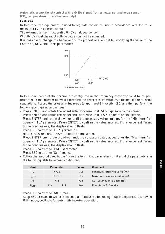
55
EN
GL
ISH
Automatic proportional control with a 0-10v signal from an external analogue sensor
(CO2, temperature or relative humidity)
Features
In this case, the equipment is used to regulate the air volume in accordance with the value
measured by an external sensor.
The external sensor must emit a 0-10V analogue sensor.
With 0-10V input the input voltage values cannot be adjusted.
It is possible to change the behaviour of the proportional output by modifying the value of the
LSP, HSP, CrL3 and CRH3 paramaters.
In this case, some of the parameters confi gured in the frequency converter must be re-pro-
grammed in the inverter to avoid exceeding the overpressure value established by the relevant
regulations. Access the programming mode (steps 1 and 2 in section 2.2) and then perform the
following confi guration changes:
- Press ENTER and rotate the wheel anti-clockwise until “SEt-” appears on the screen.
- Press ENTER and rotate the wheel anti-clockwise until “LSP” appears on the screen.
- Press ENTER and rotate the wheel until the necessary value appears for the “Minimum fre-
quency in Hz” parameter. Press ENTER to confi rm the value entered. If this value is different
to the previous one, the display should fl ash.
- Press ESC to exit the “LSP” parameter.
- Rotate the wheel until ”HSP” appears on the screen
- Press ENTER and rotate the wheel until the necessary value appears for the “Maximum fre-
quency in Hz” parameter. Press ENTER to confi rm the value entered. If this value is different
to the previous one, the display should fl ash.
- Press ESC to exit the “HSP” parameter.
- Press ESC to exit the “Set-” menu.
- Follow the method used to confi gure the two initial parameters until all of the parameters in
the following table have been confi gured:
Menú Parameter Value Comment
I_O- CrL3 7.2 Minimum reference value (mA)
I_O- CrH3 14.4 Maximum reference value (mA)
Ctl- Fr2 AI3 Current type reference (mA)
Fun- PI- PIF No Disable de PI function
- Press ESC to exit the “CtL-” menu.
- Keep ESC pressed down for 2 seconds until the 3 mode leds light up in sequence. It is now in
RUN mode, available for automatic inverter operation.
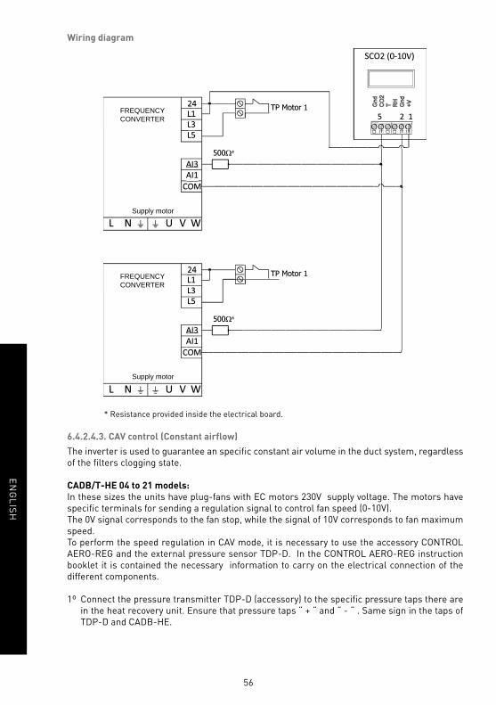
56
EN
GL
ISH
Wiring diagram
FREQUENCY CONVERTER
FREQUENCY CONVERTER
Supply motor
Supply motor
* Resistance provided inside the electrical board.
6.4.2.4.3. CAV control (Constant airfl ow)
The inverter is used to guarantee an specifi c constant air volume in the duct system, regardless
of the fi lters clogging state.
CADB/T-HE 04 to 21 models:
In these sizes the units have plug-fans with EC motors 230V supply voltage. The motors have
specifi c terminals for sending a regulation signal to control fan speed (0-10V).
The 0V signal corresponds to the fan stop, while the signal of 10V corresponds to fan maximum
speed.
To perform the speed regulation in CAV mode, it is necessary to use the accessory CONTROL
AERO-REG and the external pressure sensor TDP-D. In the CONTROL AERO-REG instruction
booklet it is contained the necessary information to carry on the electrical connection of the
different components.
1º Connect the pressure transmitter TDP-D (accessory) to the specifi c pressure taps there are
in the heat recovery unit. Ensure that pressure taps “ + “ and “ - “ . Same sign in the taps of
TDP-D and CADB-HE.

57
EN
GL
ISH
2º Perform the electrical connection and controller confi guration, following the accessory ins-
tructions of AERO-REG CONTROL.
40 and 54 models:
These models are equipped with two frequency converters (one per fan), throw these it is possi-
ble to regulate the fan speed in CAV mode (Constant air fl ow).
1º Connect the pressure transmitter TDP-D (accessory) to the specifi c pressure taps there are
in the heat recovery unit. Ensure that pressure taps “ + “ and “ - “ . Same sign in the taps of
TDP-D and CADB-HE.
2º Perform the electrical connection and confi guration of frequency converter, following these
indications in the following points:

58
EN
GL
ISH
FREQUENCY CONVERTER
Supply motor
Converter reconfi guration
Frequency converters are pre-programmed to be used via proportional control with a built-in
potentiometer (FR2 with jumper between 24V and LI3) or via PI control with a 0-10V voltage
input (FR1 with jumper between 24V and LI1).
For other uses, some of the parameters confi gured in the frequency converter must be re-
programmed. To do so, use the following inverter commands:
Step 1. Unlock the inverter
To unlock the inverter, enter the password. The sequence is as follows:
- Press ESC until “rdy” appears on the screen.
- Press ENTER and rotate the wheel anti-clockwise until “SUP-” appears on the screen.
- Press ENTER and rotate the wheel clockwise until “COd-” appears on the screen.
- Press ENTER and rotate the wheel clockwise until “1951-” appears on the screen.
- The entered code fl ashes. At this time the inverter is unprotected.
Step 2. Enter programming mode
The inverter has 2 operating MODES, RUN and PROGRAMMING. To switch from one to the other
keep ESC pressed for two seconds.
- Keep ESC pressed down for 2 seconds until the 3 mode leds light up simultaneously. At that
moment they are in Programming Mode.
Location of the 3 Mode Leds.
Depending on how they are lit up, they indicate the
selected mode:
- IN SEQUENCE Ò RUN MODE
- SIMULTANEOUSLY Ò PROGRAMMING MODE

59
EN
GL
ISH
Enter the parameters depending on the required use.
Some of the parameters confi gured in the frequency converter must be re-programmed:
- Press ENTER and rotate the wheel until “FUn-” appears on the screen.
- Press ENTER and rotate the wheel until “PI-” appears on the screen.
- Press ENTER and rotate the wheel until “rPI” appears on the screen.
- Press ENTER and rotate the wheel until the necessary value appears for the “Pressure to be
maintained” parameter. Percentage out of selected range in pressure sensor”.
Required pressure at
measurement point “P”
(Pa)
Value entered
“rPI”
Pressure sensor
pressure range
(Pa)
10 10 0-100
20 20 0-100
30 30 0-100
40 40 0-100
60 60 0-100
80 80 0-100
100 33 0-300
120 40 0-300
180 60 0-300
200 66 0-300
300 60 0-500
350 70 0-500
400 80 0-500
- Press ENTER to confi rm the value entered.
- Press ESC repeatedly until you reach the main menu.
- Keep ESC pressed down for 2 seconds until the 3 mode leds light up in sequence. It is now in
RUN mode, available for automatic inverter operation.
Step 3. Reconfi gure range in sensor
Select the TPD-D sensor pressure range in accordance with the values in the third column in
the table above.
6.4.2.4.4. COP Control (Constant pressure)
Constant Pressure (COP)
The inverter is used in multiroom ventilation systems to guarantee a constant air pressure value
in the duct system, regardless of whether the dampers are open or closed.
In both cases, the pressure must be constant in the duct system. The value of this pressure must
be determined by experimenting during the system start-up process.

60
EN
GL
ISH
CADB/T-HE 04 to 21 models:
In these sizes the units have plug-fans with EC motors 230V supply voltage. The motors have
specifi c terminals for sending a regulation signal to control fan speed (0-10V).
The 0V signal corresponds to the fan stop, while the signal of 10V corresponds to fan maximum
speed.
To perform the speed regulation in COP mode, it is necessary to use the accessory CONTROL
AERO-REG and the external pressure sensor TDP-D. In the CONTROL AERO-REG instruction
booklet it is contained the necessary information to carry on the electrical connection of the
different components.
1º Connect the pressure transmitter TDP-D (accessory) to the duct system where the heat reco-
very unit is ducted. Ensure that pressure taps “ + “ and “ - “ are in the right position according
to the following images.
AERO-REGCONTROL(Accessory)
TDP-D(Accessory)
TDP-D(Accessory)
EXTRACTIONDUCTS SYSTEM
EXTRACTIONDUCTS SYSTEM
SUPPLYDUCTS SYSTEM
SUPPLYDUCTS SYSTEM
AERO-REGCONTROL(Accessory)

61
EN
GL
ISH
40 and 54 models:
These models are equipped with two frequency converters (one per fan), throw these it is possi-
ble to regulate the fan speed in COP mode (Constant air fl ow).
1º Connect the pressure transmitter TDP-D (accessory) to the duct system where the heat reco-
very unit is ducted. Ensure that pressure taps “ + “ and “ - “ are in the right position according
to the following images.
2º Perform the electrical connection and confi guration of frequency converter, following these
indications:
FREQUENCYCONVERTER
(included)
FREQUENCYCONVERTER
(included)
TDP-D(Accessory)
TDP-D(Accessory)
TDP-D(Accessory)
EXTRACTIONDUCTS SYSTEM
EXTRACTIONDUCTS SYSTEM
SUPPLYDUCTS SYSTEM
SUPPLYDUCTS SYSTEM

62
EN
GL
ISH
FREQUENCY CONVERTER
FREQUENCY CONVERTER
Supply motor
Supply motor
FREQUENCY CONVERTER
Supply motor
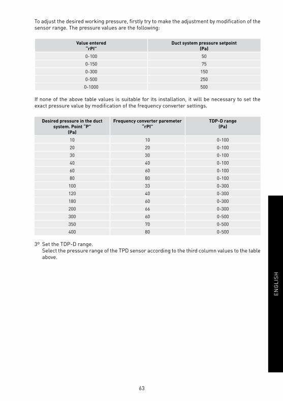
63
EN
GL
ISH
To adjust the desired working pressure, fi rstly try to make the adjustment by modifi cation of the
sensor range. The pressure values are the following:
Value entered
“rPI”
Duct system pressure setpoint
(Pa)
0-100 50
0-150 75
0-300 150
0-500 250
0-1000 500
If none of the above table values is suitable for its installation, it will be necessary to set the
exact pressure value by modifi cation of the frequency converter settings.
Desired pressure in the duct
system. Point “P”
(Pa)
Frequency converter paremeter
“rPI”
TDP-D range
(Pa)
10 10 0-100
20 20 0-100
30 30 0-100
40 40 0-100
60 60 0-100
80 80 0-100
100 33 0-300
120 40 0-300
180 60 0-300
200 66 0-300
300 60 0-500
350 70 0-500
400 80 0-500
3º Set the TDP-D range.
Select the pressure range of the TPD sensor according to the third column values to the table
above.

64
EN
GL
ISH
6.4.2.4.5. Pressure switch connection
All these range of heat recovery units have pressure tapping that allow the installation of diffe-
rencial pressure switches to perform the control of polluted fi lters. The position of the pressure
taps depends on the model:
Horizontal models
CADB/T-HE 04 to 21 LH, RH
(on the side of inlet conection
panel)
Horizontal models
CADB/T-HE 40 to 54 LH, RH
(on superior part of the side
panel)
Vertical models
CADB/T-HE 40 to 54 LV, RV
(on superior part of the side
panel)
6.5. REVERSE SUPPLY AIR/ EXTRACT AIR SIDE (only -D version)
In models CADB-HE-D 04 to CADB-HE-D 21 it is possible to reverse the supply and extract air sides. To
carry on this modifi cation it is necessary to remove the by-pass chanel and mount it in opposite sense,
as indicated in the image heresequence below:
Fig. 1 Fig. 2
Fig. 3
Fig. 5
Fig. 4
1. Disconnect the heat recovery unit.
2. Remove the side panel (fi g.1).
3. Extract carefully the bypass (fi g.2).
4. Disconnect the electrical connector that feeds the bypass.
5. Turn the bypass according to image (fi g.3 and 4).
6. Reconnect the electrical power connector of bypass.
7. Place the bypass in its housing again (fi g.5), close the panel and start up the unit.
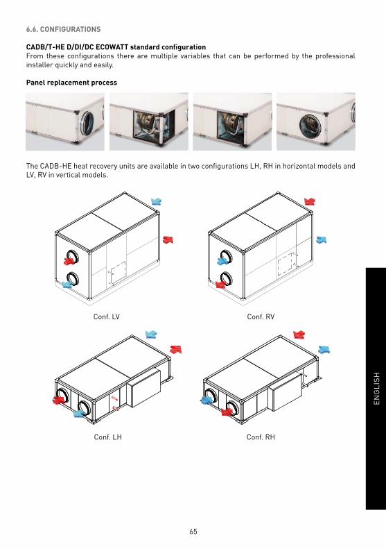
65
EN
GL
ISH
6.6. CONFIGURATIONS
CADB/T-HE D/DI/DC ECOWATT standard confi guration
From these confi gurations there are multiple variables that can be performed by the professional
installer quickly and easily.
Panel replacement process
The CADB-HE heat recovery units are available in two confi gurations LH, RH in horizontal models and
LV, RV in vertical models.
Conf. LV
Conf. LH
Conf. RV
Conf. RH

66
EN
GL
ISH
Vertical
Horizontal
Factory confi guration
LH
RH
Examples of some of the confi gurations that is possible to obtain from factory confi guration
Factory confi guration
LV
Examples of some of the confi gurations that is possible to obtain from factory confi guration
RV
EXHAUST AIR
FRESH AIR

67
EN
GL
ISH
7. INSPECTION, MAINTENANCE AND CLEANING
7.1. FILTERS
Replacement
The registers ubication for fi lters maintenance depends on the model and version. The exact ubication
of the fi lters is identifi ed by a label in the profi le that indicates the type of fi lter and its characteristics.
FALLING OBJECTS
By loosening the screws that hold the panels, they will be released. In units installed
in ceiling, pay special attention to this operation to prevent the fall of a panel. During
the maintenance signaling the area below the heat recovery unit and prevent personnel
access to it.
• Horizontal confi gurations of CADB/T-HE 04 to 21. The access to fi lters can be done by the lateral
panels and /or by the bottom panels (depending on the model):
Quick access to fi lters from the lateral panels.
Quick access to fi lters from the bottom panels.
• Horizontal confi gurations of CADB/T-HE 40 and 54. The access to fi lters can be done by the side
panels:
• Vertical confi gurations of CADB/T-HE 40 and 54. The access to fi lters can be done by two sides of
the unit, removing the specifi c panels selon in the following image:

68
EN
GL
ISH
Replacement fi lters are delivered in a plastic bag for extra protection. Remove the bag before installing
the fi lter into the unit.
Before installing the fi lter make sure that the airfl ow direction is correct. (indicated by an arrow in the
fi lter).
Filters parts table
Heat recovery
model
Ø
(mm)
AFR-HE (Accessory fi lters and spare part for CADB/T-HE)
AFR-HE G4 AFR-HE M5 AFR-HE F7 AFR-HE F9
CADB-HE D/DI/DC 04 200 AFR-HE 200/04 G4 AFR-HE 200/04 M5 AFR-HE 200/04 F7 AFR-HE 200/04 F9
CADB-HE D/DI/DC 08 250 AFR-HE 250/08 G4 AFR-HE 250/08 M5 AFR-HE 250/08 F7 AFR-HE 250/08 F9
CADB-HE D/DI/DC 16 315 AFR-HE 315/16 G4 AFR-HE 315/16 M5 AFR-HE 315/16 F7 AFR-HE 315/16 F9
CADB/T-HE D/DI/DC 21 400 AFR-HE 400/21 G4 AFR-HE 400/21 M5 AFR-HE 400/21 F7 AFR-HE 400/21 F9
CADB/T-HE D/DI/DC 40 450 AFR-HE 450/40 G4 AFR-HE 450/40 M5 AFR-HE 450/40 F7 AFR-HE 450/40 F9
CADB/T-HE D/DI/DC 54 500 AFR-HE 500/54 G4 AFR-HE 500/54 M5 AFR-HE 500/54 F7 AFR-HE 500/54 F9
7.2. FILTER INSTALLATION
The heat recovery is supplied with mounted fi lters.
Low pressure F7 fi lter for supply air and M5 for extract air. Possibility of mounting a second fi lter as
accessory.
Installation additional fi lter:
1. Loosen the two sets of fi lter support brackets.
2. Remove the fi lter holder.
3. Fit the second fi lter ensuring that the direction of air
is correct (indicated in the frame of the fi lter).
4. Ensure that the fi rst fi lter the air passes is the lower
grade of fi ltration.
5. Once both fi lters have been through fi tted place the
fi lter supports symmetrically and tighten the 4 brac-
kets.

69
EN
GL
ISH
7.3. HEAT EXCHANGER
Horizontal models CADB/T HE 04 to 21
To perform the heat exchanger cleaning it is necessary to remove it from the unit. The disassembly can
be easily done from the lateral panel:
Disassembly sequence
Models 04 to 21: Access to heat exchanger cleaning from lateral panels and from the bottom panels.
Alternatively, it is possible to disassemble the heat exchanger from the bottom panels. However, it is
necessary to perform a major number of operations to proceed.
Access to the heat exchanger for bottom sequence
FALLING OBJECTS
By loosening the screws that hold the panels, those will be released. In units installed
in ceiling, pay special attention to this operation to prevent the fall of a panel. During
the maintenance, signaling the area below the heat recovery unit and prevent personnel
access to it.
PNot manipulate the heat exchanger for the fi nned area.
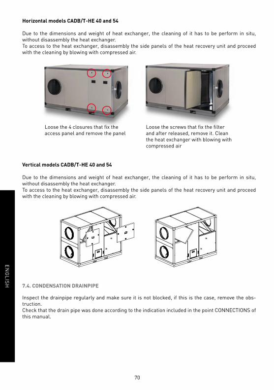
70
EN
GL
ISH
Horizontal models CADB/T-HE 40 and 54
Due to the dimensions and weight of heat exchanger, the cleaning of it has to be perform in situ,
without disassembly the heat exchanger.
To access to the heat exchanger, disassembly the side panels of the heat recovery unit and proceed
with the cleaning by blowing with compressed air.
Loose the 4 closures that fi x the
access panel and remove the panel
Loose the screws that fi x the fi lter
and after released, remove it. Clean
the heat exchanger with blowing with
compressed air
Vertical models CADB/T-HE 40 and 54
Due to the dimensions and weight of heat exchanger, the cleaning of it has to be perform in situ,
without disassembly the heat exchanger.
To access to the heat exchanger, disassembly the side panels of the heat recovery unit and proceed
with the cleaning by blowing with compressed air.
7.4. CONDENSATION DRAINPIPE
Inspect the drainpipe regularly and make sure it is not blocked, if this is the case, remove the obs-
truction.
Check that the drain pipe was done according to the indication included in the point CONNECTIONS of
this manual.

71
EN
GL
ISH
8. OPERATION ANOMALIES
8.1. GENERAL ANOMALIES
Anomaly Cause Solution
Diffi cult to start. Reduced power supply voltage.Insuffi cient static torque of motor.
Check motor specifi cation plate.Close the air inlets to reach the maximum speed.Change the motor is necessary.Contact the S&P Post-Sales service.
Insuffi cient airfl ow.Insuffi cient pressure.
Blocked pipes and/or inlet points closed.Fan obstructed.Filter overloaded.Insuffi cient rotation speed.Exchanger package blocked.
Clean inlet tubes.Clean fan.Clean or replace fi lter.Check power supply voltage.Clean the exchanger.
Reduction in performance after a period of acceptable operation.
Leaks in the circuit before and/or after the fan.Damaged roller.
Check the circuit and restore original conditions.Check the impeller and if necessary, replace with an original spare part. Contact the S&P post sales service.
New air temperature too cold.
Outside air -5º C or less.Models (CADB/T DI): Thermal protectors Support resistances open.
Insertion of post-heating resistances.Contact the S&P post sales service.Reset by pushing the button RESET, all the thermal protectors of the resistance.
Insuffi cient performance of the exchanger.
Fins dirty. Clean the exchanger.
Formation of frost on the exchanger.
Outside air below -5ºC. Insertion of post-heating devices (anti-ice).Contact the S&P Customer Advice service.
Air pulsation. Fan working in excessively low fl ow conditions.Flow instability, obstruction or bad connection.
Modifi cation of the circuit and/or replacement of the fan. Clean and/or readjust the inlet channels. Operate the electronic regulator, increasing the minimum speed (insuffi cient voltage).Contact the S&P Customer Advice service.
There is water inside the unit.
Drain clogged or wrongly dimentioned.
Check if exists a body/object obstructing the pas-sage of water and remove it. Verify that the drain trap exists and is correctly sized according to the instructins of this manual.
Only DC versions. Internal breakage of water coil.
Isolate the battery using the isolation valves.Repair the leak/ Replace the battery.
Only Dc version. The water coil is being used for cooling purpose with cold water.
The CADB-HE DC heat recovery can be used just for post-heating function with hot water.

S&P SISTEMAS DE VENTILACIÓN, S.L.U.
C. Llevant, 4
Polígono Industrial Llevant
08150 Parets del Vallès
Barcelona - España
Tel. +34 93 571 93 00
Fax +34 93 571 93 01
www.solerpalau.com
Ref. 7081011400