anisotropic cohesive soils Soluciones de forma cerrada ... · Palabras Clave: Zapatas someras,...
17
Revista Ingeniería de Construcción RIC Vol 30 Nº2 2015 www.ricuc.cl ENGLISH VERSION…………...................................................................................................................................................................................................................................... Revista Ingeniería de Construcción Vol 30 Nº2 Agosto de 2015 www.ricuc.cl 109 Closed-form solutions for bearing capacity of footing on anisotropic cohesive soils Soluciones de forma cerrada para la capacidad de carga de zapatas en suelos anisotrópicos cohesivos Mosleh Ali Al-Shamrani*, Arif Ali Baig Moghal 1 * * Department of Civil Engineering, College of Engineering. King Saud University, Riyadh. SAUDI ARABIA Fecha de Recepción: 17/06/2015 Fecha de Aceptación: 14/07/2015 PAG 109-125 Abstract Simple closed-form solutions for the undrained bearing capacity of strip footings on anisotropic cohesive soils are derived employing kinematical approach of limit analysis. Both modified Hill-type and translational failure mechanisms, with variable wedge angles, are attempted and the best upper bound for each mechanism has been analytically determined leading to an analytical expression for the bearing capacity factor. The influence of degree of soil anisotropy on the corresponding value for the bearing capacity factor has also been evaluated. For a wide range of degree of anisotropy, the improvement in the predicted upper bound values does not warrant the use of the modified Hill-type mechanism. Instead, the conventional Hill-type failure mechanism, with a fixed wedge angle of π/4, provides a simple and concise analytical expression for the bearing capacity factor that is analytically equivalent to the conventional Prandtl - Reissner bearing capacity factor for the case of isotropic soil multiplied by the average of the sum of degree of anisotropy plus unity. Keywords: Shallow footings, soil anisotropy, limit analysis, upper-bound method, failure mechanisms, closed-form solution Resumen Las soluciones de forma cerrada simples para la capacidad de carga no drenada de zapatas escalonadas en suelos isotrópicos cohesivos se derivan al emplear el enfoque cinemático del análisis de límites. Se intentan utilizar tanto el mecanismo traslacional de fallas como el mecanismo modificado tipo Hill, con ángulos de incidencia variables. Se ha determinado, de forma analítica, la mejor cota superior para cada mecanismo, lo cual nos lleva a una expresión analítica para el factor de capacidad de carga. También se ha evaluado la influencia del grado de anisotropía del suelo en el valor correspondiente para el factor de capacidad de carga. Para un amplio rango de grados de anisotropía, la mejora en los valores predichos de la cota superior no garantiza el uso del mecanismo modificado del tipo Hill. En vez de eso, el mecanismo convencional de falla del tipo Hill, con un ángulo de incidencia fijo de π/4, nos entrega una expresión simple y concisa para el factor de capacidad de carga que es analíticamente equivalente al factor convencional de capacidad de carga de Prandtl-Reissner, para el caso de suelos isotrópicos multiplicado por el promedio de la suma del grado de anisotropía más la unidad. Palabras Clave: Zapatas someras, anisotropía del suelo, análisis de límites, método de cota superior, mecanismo de fallas, solución de forma cerrada 1. Introduction The ultimate bearing capacity of foundations is commonly estimated based on the assumption that the soil is isotropic with respect to shear strength. However, clay strata are usually deposited and consolidated under one- dimensional conditions, and hence most naturally occurring clays are inherently anisotropic (Ward et al., 1965; Bishop, 1966). This results in horizontal bedding planes having strength and other physical properties different in horizontal and vertical directions. The anisotropy is mainly attributed to the process of sedimentation followed by predominantly one-dimensional consolidation that leads to preferred orientation of clay particles which tend to become oriented perpendicularly to the major consolidating stress. Because of soil anisotropy, the undrained shear strength varies with the orientation of the failure plane. In the bearing capacity problem, the direction of the principal stresses along any assumed failure surface changes from one point to the other. Therefore, it is more realistic to use values of strength appropriate to each orientation of the failure plane. This is of a prime importance especially for the case of analytical solutions where the undrained bearing capacity is solely function of one soil parameter (i.e. undrained shear strength), contrary to computational solutions where the soil behaviour is characterized by several constitutive parameters, albeit with different level of importance. There have been several attempts pertaining to the evaluation of the bearing capacity of footings on cohesive soils that took into account anisotropy in shear strength. Using the limit equilibrium approach and assuming a circular failure surface, Menzies (1976) presented a correction factor for the influence of strength anisotropy on the predicted bearing capacity. Employing the method of limit equilibrium, Reddy and Srinivasan (1967) adopted a circular failure mechanism for the analysis of bearing capacity of footings over soils with non-homogeneous and anisotropic strength. The parameters describing the geometry of the mechanism were varied, and the results were presented in the form of dimensionless design charts. Adopting the same circular failure mechanism, but using the upper bound approach of limit analysis, Chen (1975) presented solution that agreed with the previously obtained Reddy and Srinivasan (1967) limit equilibrium method solution. Although the use of the circular mechanism presumably simplifies the mathematical analysis, this mode of failure does not provide the best solution. Davis and Christian (1971) presented solution for the bearing capacity of anisotropic clays by use of the slip- line method. A correction coefficient for the bearing capacity factor was presented in a graphical form as a function of the soil strength parameters. Assuming a failure mechanism similar to Prandtl-type mechanism, but with varying boundary wedge angles, Reddy and Rao (1981) 1 Corresponding author: Assistant Professor. Bugshan Research Chair in Expansive Soils, Department of Civil Engineering, College of Engineering, King Saud University. Riyadh – 11421 E-mail: [email protected]
Transcript of anisotropic cohesive soils Soluciones de forma cerrada ... · Palabras Clave: Zapatas someras,...
Revista Ingeniería de Construcción RIC Vol 30 Nº2 2015 www.ricuc.cl
ENGLISH VERSION…………......................................................................................................................................................................................................................................
Revista Ingeniería de Construcción Vol 30 Nº2 Agosto de 2015 www.ricuc.cl 109
Closed-form solutions for bearing capacity of footing on anisotropic cohesive soils Soluciones de forma cerrada para la capacidad de carga de zapatas en suelos anisotrópicos cohesivos
Mosleh Ali Al-Shamrani*, Arif Ali Baig Moghal1*
* Department of Civil Engineering, College of Engineering. King Saud University, Riyadh. SAUDI ARABIA
Fecha de Recepción: 17/06/2015
Fecha de Aceptación: 14/07/2015 PAG 109-125
Abstract Simple closed-form solutions for the undrained bearing capacity of strip footings on anisotropic cohesive soils are derived employing kinematical approach of limit analysis. Both modified Hill-type and translational failure mechanisms, with variable wedge angles, are attempted and the best upper bound for each mechanism has been analytically determined leading to an analytical expression for the bearing capacity factor. The influence of degree of soil anisotropy on the corresponding value for the bearing capacity factor has also been evaluated. For a wide range of degree of anisotropy, the improvement in the predicted upper bound values does not warrant the use of the modified Hill-type mechanism. Instead, the conventional Hill-type failure mechanism, with a fixed wedge angle of π/4, provides a simple and concise analytical expression for the bearing capacity factor that is analytically equivalent to the conventional Prandtl - Reissner bearing capacity factor for the case of isotropic soil multiplied by the average of the sum of degree of anisotropy plus unity. Keywords: Shallow footings, soil anisotropy, limit analysis, upper-bound method, failure mechanisms, closed-form solution Resumen Las soluciones de forma cerrada simples para la capacidad de carga no drenada de zapatas escalonadas en suelos isotrópicos cohesivos se derivan al emplear el enfoque cinemático del análisis de límites. Se intentan utilizar tanto el mecanismo traslacional de fallas como el mecanismo modificado tipo Hill, con ángulos de incidencia variables. Se ha determinado, de forma analítica, la mejor cota superior para cada mecanismo, lo cual nos lleva a una expresión analítica para el factor de capacidad de carga. También se ha evaluado la influencia del grado de anisotropía del suelo en el valor correspondiente para el factor de capacidad de carga. Para un amplio rango de grados de anisotropía, la mejora en los valores predichos de la cota superior no garantiza el uso del mecanismo modificado del tipo Hill. En vez de eso, el mecanismo convencional de falla del tipo Hill, con un ángulo de incidencia fijo de π/4, nos entrega una expresión simple y concisa para el factor de capacidad de carga que es analíticamente equivalente al factor convencional de capacidad de carga de Prandtl-Reissner, para el caso de suelos isotrópicos multiplicado por el promedio de la suma del grado de anisotropía más la unidad. Palabras Clave: Zapatas someras, anisotropía del suelo, análisis de límites, método de cota superior, mecanismo de fallas, solución de forma cerrada
1. Introduction The ultimate bearing capacity of foundations is commonly estimated based on the assumption that the soil is isotropic with respect to shear strength. However, clay strata are usually deposited and consolidated under one-dimensional conditions, and hence most naturally occurring clays are inherently anisotropic (Ward et al., 1965; Bishop, 1966). This results in horizontal bedding planes having strength and other physical properties different in horizontal and vertical directions. The anisotropy is mainly attributed to the process of sedimentation followed by predominantly one-dimensional consolidation that leads to preferred orientation of clay particles which tend to become oriented perpendicularly to the major consolidating stress. Because of soil anisotropy, the undrained shear strength varies with the orientation of the failure plane. In the bearing capacity problem, the direction of the principal stresses along any assumed failure surface changes from one point to the other. Therefore, it is more realistic to use values of strength appropriate to each orientation of the failure plane. This is of a prime importance especially for the case of analytical solutions where the undrained bearing capacity is solely function of one soil parameter (i.e. undrained shear strength), contrary to computational
solutions where the soil behaviour is characterized by several constitutive parameters, albeit with different level of importance. There have been several attempts pertaining to the evaluation of the bearing capacity of footings on cohesive soils that took into account anisotropy in shear strength. Using the limit equilibrium approach and assuming a circular failure surface, Menzies (1976) presented a correction factor for the influence of strength anisotropy on the predicted bearing capacity. Employing the method of limit equilibrium, Reddy and Srinivasan (1967) adopted a circular failure mechanism for the analysis of bearing capacity of footings over soils with non-homogeneous and anisotropic strength. The parameters describing the geometry of the mechanism were varied, and the results were presented in the form of dimensionless design charts. Adopting the same circular failure mechanism, but using the upper bound approach of limit analysis, Chen (1975) presented solution that agreed with the previously obtained Reddy and Srinivasan (1967) limit equilibrium method solution. Although the use of the circular mechanism presumably simplifies the mathematical analysis, this mode of failure does not provide the best solution. Davis and Christian (1971) presented solution for the bearing capacity of anisotropic clays by use of the slip-line method. A correction coefficient for the bearing capacity factor was presented in a graphical form as a function of the soil strength parameters. Assuming a failure mechanism similar to Prandtl-type mechanism, but with varying boundary wedge angles, Reddy and Rao (1981)
1 Corresponding author:
Assistant Professor. Bugshan Research Chair in Expansive Soils, Department of Civil Engineering, College of Engineering, King Saud University. Riyadh – 11421 E-mail: [email protected]
Revista Ingeniería de Construcción RIC Vol 30 Nº2 2015 www.ricuc.cl
ENGLISH VERSION…………......................................................................................................................................................................................................................................
Revista Ingeniería de Construcción Vol 30 Nº2 Agosto de 2015 www.ricuc.cl 110
used the upper bound approach of limit analysis for the evaluation of bearing capacity for anisotropic and non-homogeneous clays. Although the solution is rigorous within the concept of limit analysis, however the derived expression is exceedingly cumbersome and the least upper bound could only be obtained numerically by a process of trial-and-error (heuristically) or with the aid of iterative rigorous optimization technique. Evidently, irrespective of the method of analysis and the adopted failure mechanism, all available solutions for the bearing capacity of footings on anisotropic soils present results in the form of graphs relating the ultimate bearing capacity to soil and failure mechanism parameters. Presenting results for a wide range of useful combinations of all parameters generally requires a large number of diagrams. Furthermore, an advantage of the closed-form solution is that it clearly depicts the effect of soil anisotropy on the bearing capacity as opposed to tabular or graphical representations where such an effect is obstructed in a number of charts and/or tables. In addition, the use of graphs and tables in design practice is not convenient for computer computations. It would therefore be reasonable for one to contemplate that, partly because of the lack of a simple closed-form solution; computations of the bearing capacity of footing on anisotropic soils remain, to some extent, a research topic with less practical applications. This paper presents closed-form solutions for the ultimate bearing capacity of strip footings placed on the surface of anisotropic clays. The solutions are obtained using the upper bound method of limit analysis (Drucker et al., 1952), and expressions for the bearing capacity factor are derived for modified Hill-type and translational failure mechanisms. The strength in any direction in the vertical-horizontal plane is expressed in terms of the strength in the principal direction according to the functional relationship suggested by Casagrande and Carillo (1944). The effect of anisotropy on the predicted bearing capacity is demonstrated, and the results are compared with available pertinent solutions.
2. Method of analysis With the advent of powerful computers and the development of modern computational methods the ability to analyze problems has, for the first time, outstripped our ability to describe the material (Drucker, 1991). However, despite the development of a variety of computational methods, which makes solutions for many complicated problems attainable, it is still of a prime importance to carry out simple analytical computations to gauge the results from such rather elaborate numerical analyses. The slip-line, limit equilibrium, and limit analysis methods are traditionally the most common analytical methods used to solve stability problems in geotechnical engineering. Although the limit analysis method is a relatively new technique, compared with the slip-line and limit equilibrium methods, it has found a wide application for solution of conventional geotechnical stability problems, including bearing capacity of footings (Chen and Davidson, 1973; Florkiewicz, 1989; Michalowski, 1997; Ukritchon et al., 1998, Kumar and Kouzer, 2007; Kumar and Kouzer, 2008a; Kumar and Khatri, 2011) lateral earth pressure problems (Chen and Rosenfarb, 1973), stability of slopes (Chen and Giger, 1971; Izbicki, 1981), and vertical cuts
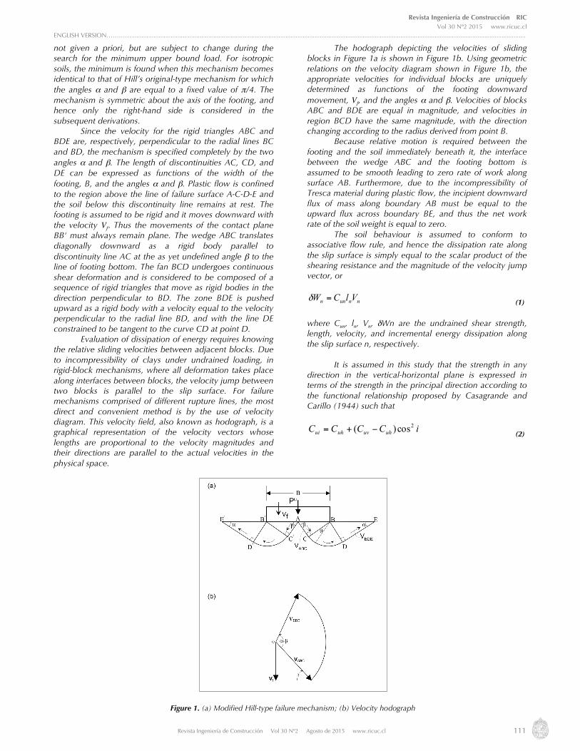
(Drescher, 1983; Su et al., 1998; Kumar and Kouzer, 2008b). The theory provides upper and lower bounds that serve to bracket the limit load for rigid-perfectly plastic materials, and computations of the two bounds is generally referred to as limit analysis (Chen, 1975). Contrary to the kinematic approach which has been used so successfully, the lower bound has been less frequently applied to geotechnical engineering problems. This is because it is considerably more difficult to construct a good statically admissible stress field than it is to construct a good kinematically admissible failure mechanism (Sloan, 1988). The upper bound theorem of limit analysis states that: for a perfectly plastic material with an associated flow rule, the collapse must occur for any kinematically admissible failure mechanism if the rate of work done by a set of external forces in an increment of displacement equals or exceeds the rate of energy done by internal stresses (Chen, 1975). A kinematically admissible velocity field is one that satisfies the compatibility equations, the flow rule, and the velocity boundary conditions. During plastic flow, power is dissipated by plastic yielding of the soil mass and by sliding along velocity discontinuities, where jumps in the normal and tangential velocities can occur. 2.1 Upper-bound solutions for bearing capacity The first essential step in the upper bound approach of limit analysis is the postulation of a kinematically admissible failure mechanism (also known as velocity field) in terms of geometric parameters (e.g. radius of curvature, slip surface angle, etc.). Equating the rate of work of external forces to the rate of internal energy dissipation, an expression for the collapse load is obtained as a function of the material properties and geometry of the failure mechanism. The geometric parameters of the failure mechanism are then varied in an optimization scheme either by trial-and-error procedure or by means of mathematics to yield the minimum dissipated power, and hence the best upper bound for the particular failure mechanism. Several classes of collapse mechanisms may be investigated, and the least upper bound obtained from all attempted mechanisms is considered the best upper bound of the true limit load. In this investigation, several of the commonly known kinematically admissible failure mechanisms for the bearing capacity problem have been attempted. The objective was not only to obtain the least upper bound possible to the bearing capacity, but also to fulfil the prime objective of this paper of obtaining a closed-form expression for the bearing capacity factor. It was not clear a priori which mechanism would predict the least bearing capacity or the one which would yield a closed-form expression for the bearing capacity factor. The two mechanisms presented herein are a modified Hill-type mechanism and a translational mechanism. 2.2 Modified hill-type mechanism The first failure mechanism considered is shown in Figure 1a. It consists of rigid triangle wedges ABC and AB'C' with base angles β and π/2-β; radial shear zones BCD and B'C'D' of central angle α+β; and passive Rankine’s triangular wedges BDE and B'D'E' with base angles α and π/2-α. The mechanism shown in Fig. 1a resembles that of Hill-type; however, the angles α and β are
Revista Ingeniería de Construcción RIC Vol 30 Nº2 2015 www.ricuc.cl
ENGLISH VERSION…………......................................................................................................................................................................................................................................
Revista Ingeniería de Construcción Vol 30 Nº2 Agosto de 2015 www.ricuc.cl 111
not given a priori, but are subject to change during the search for the minimum upper bound load. For isotropic soils, the minimum is found when this mechanism becomes identical to that of Hill’s original-type mechanism for which the angles α and β are equal to a fixed value of π/4. The mechanism is symmetric about the axis of the footing, and hence only the right-hand side is considered in the subsequent derivations. Since the velocity for the rigid triangles ABC and BDE are, respectively, perpendicular to the radial lines BC and BD, the mechanism is specified completely by the two angles α and β. The length of discontinuities AC, CD, and DE can be expressed as functions of the width of the footing, B, and the angles α and β. Plastic flow is confined to the region above the line of failure surface A-C-D-E and the soil below this discontinuity line remains at rest. The footing is assumed to be rigid and it moves downward with the velocity Vf. Thus the movements of the contact plane BB' must always remain plane. The wedge ABC translates diagonally downward as a rigid body parallel to discontinuity line AC at the as yet undefined angle β to the line of footing bottom. The fan BCD undergoes continuous shear deformation and is considered to be composed of a sequence of rigid triangles that move as rigid bodies in the direction perpendicular to BD. The zone BDE is pushed upward as a rigid body with a velocity equal to the velocity perpendicular to the radial line BD, and with the line DE constrained to be tangent to the curve CD at point D. Evaluation of dissipation of energy requires knowing the relative sliding velocities between adjacent blocks. Due to incompressibility of clays under undrained loading, in rigid-block mechanisms, where all deformation takes place along interfaces between blocks, the velocity jump between two blocks is parallel to the slip surface. For failure mechanisms comprised of different rupture lines, the most direct and convenient method is by the use of velocity diagram. This velocity field, also known as hodograph, is a graphical representation of the velocity vectors whose lengths are proportional to the velocity magnitudes and their directions are parallel to the actual velocities in the physical space.
The hodograph depicting the velocities of sliding blocks in Figure 1a is shown in Figure 1b. Using geometric relations on the velocity diagram shown in Figure 1b, the appropriate velocities for individual blocks are uniquely determined as functions of the footing downward movement, Vf, and the angles α and β. Velocities of blocks ABC and BDE are equal in magnitude, and velocities in region BCD have the same magnitude, with the direction changing according to the radius derived from point B. Because relative motion is required between the footing and the soil immediately beneath it, the interface between the wedge ABC and the footing bottom is assumed to be smooth leading to zero rate of work along surface AB. Furthermore, due to the incompressibility of Tresca material during plastic flow, the incipient downward flux of mass along boundary AB must be equal to the upward flux across boundary BE, and thus the net work rate of the soil weight is equal to zero. The soil behaviour is assumed to conform to associative flow rule, and hence the dissipation rate along the slip surface is simply equal to the scalar product of the shearing resistance and the magnitude of the velocity jump vector, or
nnunn VlCW =δ (1) where Cun, ln, Vn, δWn are the undrained shear strength, length, velocity, and incremental energy dissipation along the slip surface n, respectively. It is assumed in this study that the strength in any direction in the vertical-horizontal plane is expressed in terms of the strength in the principal direction according to the functional relationship proposed by Casagrande and Carillo (1944) such that
iCCCC uhuvuhui2cos)( −+= (2)
Figure 1. (a) Modified Hill-type failure mechanism; (b) Velocity hodograph
Revista Ingeniería de Construcción RIC Vol 30 Nº2 2015 www.ricuc.cl
ENGLISH VERSION…………......................................................................................................................................................................................................................................
Revista Ingeniería de Construcción Vol 30 Nº2 Agosto de 2015 www.ricuc.cl 112
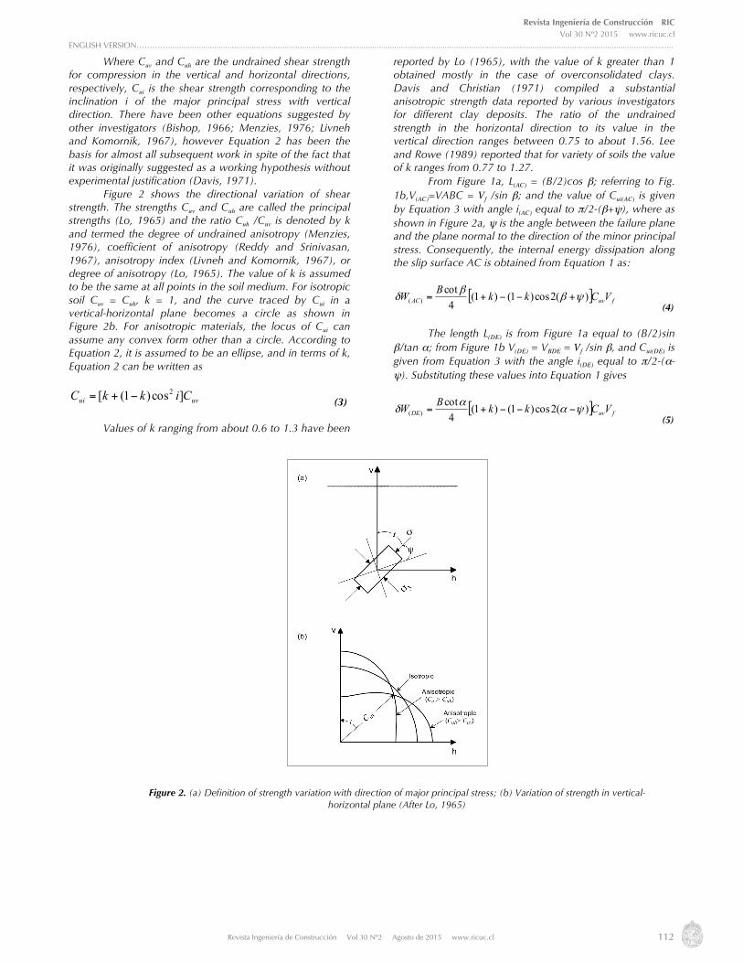
Where Cuv and Cuh are the undrained shear strength for compression in the vertical and horizontal directions, respectively, Cui is the shear strength corresponding to the inclination i of the major principal stress with vertical direction. There have been other equations suggested by other investigators (Bishop, 1966; Menzies, 1976; Livneh and Komornik, 1967), however Equation 2 has been the basis for almost all subsequent work in spite of the fact that it was originally suggested as a working hypothesis without experimental justification (Davis, 1971). Figure 2 shows the directional variation of shear strength. The strengths Cuv and Cuh are called the principal strengths (Lo, 1965) and the ratio Cuh /Cuv is denoted by k and termed the degree of undrained anisotropy (Menzies, 1976), coefficient of anisotropy (Reddy and Srinivasan, 1967), anisotropy index (Livneh and Komornik, 1967), or degree of anisotropy (Lo, 1965). The value of k is assumed to be the same at all points in the soil medium. For isotropic soil Cuv = Cuh, k = 1, and the curve traced by Cui in a vertical-horizontal plane becomes a circle as shown in Figure 2b. For anisotropic materials, the locus of Cui can assume any convex form other than a circle. According to Equation 2, it is assumed to be an ellipse, and in terms of k, Equation 2 can be written as
uvui CikkC ]cos)1([ 2−+= (3) Values of k ranging from about 0.6 to 1.3 have been
reported by Lo (1965), with the value of k greater than 1 obtained mostly in the case of overconsolidated clays. Davis and Christian (1971) compiled a substantial anisotropic strength data reported by various investigators for different clay deposits. The ratio of the undrained strength in the horizontal direction to its value in the vertical direction ranges between 0.75 to about 1.56. Lee and Rowe (1989) reported that for variety of soils the value of k ranges from 0.77 to 1.27. From Figure 1a, L(AC) = (B/2)cos β; referring to Fig. 1b,V(AC)=VABC = Vf /sin β; and the value of Cui(AC) is given by Equation 3 with angle i(AC) equal to π/2-(β+ψ), where as shown in Figure 2a, ψ is the angle between the failure plane and the plane normal to the direction of the minor principal stress. Consequently, the internal energy dissipation along the slip surface AC is obtained from Equation 1 as:
[ ] fuvAC VCkkBW )(2cos)1()1(4cot
)( ψββ
δ +−−+= (4)
The length L(DE) is from Figure 1a equal to (B/2)sin β/tan α; from Figure 1b V(DE) = VBDE = Vf /sin β, and Cui(DE) is given from Equation 3 with the angle i(DE) equal to π/2-(α-ψ). Substituting these values into Equation 1 gives
[ ] fuvDE VCkkBW )(2cos)1()1(4cot
)( ψαα
δ −−−+= (5)
Figure 2. (a) Definition of strength variation with direction of major principal stress; (b) Variation of strength in vertical-horizontal plane (After Lo, 1965)

Revista Ingeniería de Construcción RIC Vol 30 Nº2 2015 www.ricuc.cl
ENGLISH VERSION…………......................................................................................................................................................................................................................................
Revista Ingeniería de Construcción Vol 30 Nº2 Agosto de 2015 www.ricuc.cl 113
The rate of energy dissipation along the discontinuity curve CD is calculated by multiplying the differential area rdθ by undrained shear strength Cui given from Equation 3, times the velocity jump vector across the line whose magnitude is equal to Vf /sin β, and integrating over the whole surface, or
[ ] θβδβα
rdVCikkW fuvCDCD )sin/(cos)1(0 )(
2)( ∫
+−+=
(6) The radius of the slip fan, r = (B/2)sin β, for any point on the failure surface CD the inclination angle i(CD) is equal to π/2-β+θ-ψ Substituting the values for r and angle i(CD) into Equation 6 ad integrating gives
fuvCD VCkkBW ⎥⎦
⎤⎢⎣
⎡ +−−−+++= ))(2sin)(2)(sin1(21))(1(
4)( ψβαψβαδ (7)
The rate of energy dissipation in the radial shear zone BCD is given by multiplying the length of the radial line by the undrained shear strength along the line times the velocity jump vector across the line which is equal to Vf /sin β, and integrating over the angle α+β, or
θβδβα
rdVCW fBCDuiBCD )sin/(0 )()( ∫+
= (8)
Substituting into Equation 8 the value of r and that of Cui(BCD) as obtained from Equation 3 with i(BCD) = β-θ-ψ, yields
fuvBCD VCkkBW ⎥⎦
⎤⎢⎣
⎡ −++−+++= ))(2sin)(2)(sin1(21))(1(
4)( ψβψαβαδ (9)
The rate of external work done by the foundation load Pu is given by
fuVPE =δ (10)
Combining Equations 4, 5, 7, and 9, and multiplying by two for both sides of the mechanism, gives the total rates of internal energy dissipation. Equating the total rate of internal energy dissipation thus obtained to the rate of external work, the upper bound for the foundation load, Pu, is expressed as
( )uv
u Ck
kBP ⎥⎦
⎤⎢⎣
⎡
+−−
++++=
)2coscot2cos(cot2cos)1( )(2cotcot)1(
2 ααββψ
βααβ
(11) To get the least upper bound requires minimization of Pu with respect to angles β and α, or
0=∂α∂ uP
(12a) and
0 =∂β∂ uP
(12b)
From Equations 11 and 12, and after algebraic manipulation and simplification, we have
k)cos2-(1
)cos2 k)-(1-k)(1=tan2sin2 ⎥⎦
⎤⎢⎣
⎡ +
ψψ
αα (13a)
and
k)cos2-(1
)cos2 k)-(1-k)(1=tan2sin2 ⎥⎦
⎤⎢⎣
⎡ +
ψψ
ββ (13b)
It is evident from Equations 13a and 13b that α = β, and hence in terms of β Equation 11 reduces to:
uvacM
u CNq = (14) Where uq is the ultimate bearing capacity; equal to the
ultimate load Pu divided by the area of the footing and acMN is the anisotropic bearing capacity factor associated
with the modified Hill-type mechanism (Figure1a) and is given by
( ) ββψββ 2coscot2cos)1(2cot)1( kkN acM −−++= (15)
Evaluation of bearing capacity from Equation 14 needs first the determination of the failure mechanism angle β from Equation 13b. It is the only unknown variable in Equation 13b; however it cannot be solved for explicitly. It can however be determined by a process of trial-and-error and the determined value is then entered into Equation 15 for evaluation of the factor a
cMN which in turns is substituted
into Equation 14 to give the corresponding bearing capacity value. As we know for the case of isotropic strength the optimum value for angle β is 45°. Subsequently it will be demonstrated that for the common range of values for degree of anisotropy the optimum value for β is ≈ 45° ± 3°, and hence the term sin2β in Equation 13b can virtually be set equal to unity, and the value of β can be expressed explicitly. 2.3 Translational Mechanism The second mechanism considered consists, as shown in Figure 3a, of sliding blocks separated by internal planar rupture surfaces. It approximates the modified Hill-type mechanism (Figure 1a), where the slip fan or shear zone region BCD in Figure 1a is replaced with the rigid block BCD in Figure 3a. Therefore, no deformation takes place within the region BCD, and for the entire mechanism the power is dissipated solely at the interfaces between adjacent blocks, which constitute velocity discontinuities. Since the mechanism is symmetrical about the axis of the footing, it is only necessary to consider the movement on the right-hand side of Figure 3a.

Revista Ingeniería de Construcción RIC Vol 30 Nº2 2015 www.ricuc.cl
ENGLISH VERSION…………......................................................................................................................................................................................................................................
Revista Ingeniería de Construcción Vol 30 Nº2 Agosto de 2015 www.ricuc.cl 114
The rigid blocks in the mechanism are separated by velocity discontinuities AC, BC, CD, BD, and DE. The footing moves downward at velocity Vf, and velocities of particular blocks can be obtained from geometrical relations in the hodograph shown in Figure 3b. The wedge ABC translates at an angle η with the horizontal. This movement is accommodated by the lateral movement of the adjacent block BCD which in turns pushes up the wedge BDE. The two triangles BCD and BDE move as rigid bodies in the direction parallel to CD and DE, respectively. From Figure 3a, L(AC) = B/(4cos η); referring to Figure 3b, V(AC) = Vf /sin η; and substituting the value of Cui(AC) is obtained from Equation 3 with i(AC) = π/2 -(β+ψ). Accordingly, the internal energy dissipation along slip plane AC is obtained from Equation 1 as
[ ] fuvAC VCkkBW )(2cos)1()1(sincos8)( ψηηη
δ +−−+= (16)
Instead of using the angles η and ζ shown in Figure 3a and Figure 3b, it was found more convenient to define the lengths of discontinuities and the velocity increments in terms of the footing width, B, the mechanism depth, d, and the lateral extent of the mechanism from the edge of the footing, h. Therefore, in terms of parameters d and h Equation 16 becomes
[ ] fuvAC VCkkdBdW )(2cos)1()1(
3216 22
)( ψηδ +−−+⎟⎟⎠
⎞⎜⎜⎝
⎛ +=
(17) The length, velocity increment, and shear strength along the slip plane BC are identical to the corresponding values along discontinuity AC, and hence the rate of energy dissipation along plane BC is also given by Equation 17. From the geometry of Figure 3a, the length of the slip plane
is L(BD)= h/(2 cos ζ), the inclination angle i(BD) is equal to π/2-(α-ψ), and referring to Figure 3b the velocity increment
is ζη costan)(
fBD
VV = .
Accordingly, from Equations 1 and 3 one gets
fuvBD VCkkdhhdBW )](2cos)1()1[(
164 22
)( ψζδ −−−+⎟⎟⎠
⎞⎜⎜⎝
⎛ +=
(18) Because the length, velocity increment, and shear strength along the slip plane DE are identical to those along discontinuity BD, the rate of energy dissipation along DE is also given by Equations 18. From the geometry of Figure 3a, the length of the slip plane L(CD) is equal to (b+2h)/4, from Figure 3b the velocity increment V(CD) = 2 Vf /tan η; and the undrained shear strength Cui(CD) is obtained from Equation 3 with the inclination angle i(CD) = π/2-ψ, and hence from Equation 1 the internal energy dissipation along discontinuity CD is after simplification given as
[ ] fuvCD VCkkdhBBW )2cos)1()1(
162
)( ψδ −−+⎟⎠
⎞⎜⎝
⎛ +=
(19) Summing rates of energy dissipation along discontinuities AC, BC, CD, BD, and DE, and multiplying by two for both sides of the mechanism, gives the total rates of internal energy dissipation. Equating the total rate of internal energy dissipation thus obtained to the total rate at which the work is done by the force on the foundation (Equation 10), after some algebraic manipulations the limit load is given by
uvu C
BdBhhBhdkBdBhhBhdk
dhP
⎥⎥⎦
⎤
⎢⎢⎣
⎡
+−−−+
++++=
ψ2cos)428)(1( )428)(1(
41
2222
2222
20)
Figure 3. (a) Translational failure mechanism; (b) Velocity hodograph

Revista Ingeniería de Construcción RIC Vol 30 Nº2 2015 www.ricuc.cl
ENGLISH VERSION…………......................................................................................................................................................................................................................................
Revista Ingeniería de Construcción Vol 30 Nº2 Agosto de 2015 www.ricuc.cl 115
The best upper bound in Equation 20 is found by minimizing Pu with respect to the variables d and h, or
0 =dPu
∂∂
(21a) and
0=hPu
∂∂
(21b) From Equations 20, 21a and 21b, we get
⎥⎦
⎤⎢⎣
⎡
−−+
−++=
ψψ2cos)1()1(2cos)1)1(22
1
kkkkB
d
(22) and
21
=Bh
(23) It is noted from Equation 23 that the length h is function only of the footing width and hence the lateral extent of the failure mechanism is independent of the degree of soil anisotropy. Setting k =1, from Equation 22,
d/B = ( )22/1 which is exactly the value obtained by Chen (1975) for the case of soils with isotropic shear strength. Substituting Equations 22 and 23 into Equation 20, the least upper bound obtained for the translational mechanism of Figure 3a is given by
uvacT
u CNq = (24)
where acTN is the bearing capacity factor for strip footing
on anisotropic cohesive soils obtained based on the translational mechanism depicted in Figure 3a, and is expressed as
( ) ( )[ ]21
222 2cos1122 ψkkN acT −−+= (25)
Equation 25 has the advantage that it yields directly, and without recourse to supplementary graphs, an expression for the bearing capacity factor for a strip footing on the surface of anisotropic cohesive soil. Setting k = 1
gives acTN = 4√2, which is exactly the value obtained by
Chen (1975) for the case of soils with isotropic undrained shear strength.
3. Results and discussion The values for the bearing capacity factors a
cMN
(Equation 15) and acTN (Equation 25), for degree of
anisotropy ranging from 0.5 to 2.0, are tabulated in columns 2 and 5 of Table 1, respectively. Although for practical purposes the value for the bearing capacity factor need to be estimated with only one digit past the decimal
point, for reasons of comparison all results in Table 1 are truncated to three digits. Inspection of the data in Table 1 shows that soil anisotropy has a profound effect on the value of bearing capacity factor. For the case of modified Hill-type mechanism, the change in the value of a
cMN was about 34%
when k changed from 1.0 to 0.50. Changing the value of k from 1.0 to 2.0 the increase in the value for a
cMN was
about 50%. Almost the same proportionality of change holds true for the a
cTN values for the case of the translational
mechanism (column 5 of Table 1). It is evident therefore that neglecting anisotropy and assuming that the strength in all directions is equal to the vertical strength is considerably on the unsafe side for k less than one and conservative for k values greater than one. The degree of vulnerability and conservatism increases as k becomes far less and far more than unity, respectively. Figure 4 shows the relationship between soil degree of anisotropy and the bearing capacity factors a
cMN and acTN . It is noted that, irrespective of the degree of soil
anisotropy, acMN values are consistently lower than those of
acTN . As shown in Figure 5, the discrepancy between the
two solutions increased as the degree of anisotropy increased and it reached its maximum value of about 10% when k factor approached unity, which represents the case when the shear strength is isotropic, and then started to decrease again. However, considering the uncertainties associated with measured soil properties, the deviation
between the values of acMN and a
cTN is well within
acceptable limits for practical applications.

Revista Ingeniería de Construcción RIC Vol 30 Nº2 2015 www.ricuc.cl
ENGLISH VERSION…………......................................................................................................................................................................................................................................
Revista Ingeniería de Construcción Vol 30 Nº2 Agosto de 2015 www.ricuc.cl 116
Degree of Anisotropy, k
Angle β from Eq. 13b Angle β from Eq. 26
0.5 3.842 3.842 3.856 4.209
0.6 4.105 4.105 4.113 4.506
0.8 4.626 4.626 4.627 5.087
1.0 5.142 5.142 5.142 5.657
1.2 5.655 5.656 5.656 6.219
1.4 6.166 6.166 6.170 6.775
1.6 6.675 6.675 6.684 7.326
1.8 7.184 7.184 7.198 7.874
2.0 7.693 7.693 7.712 8.419
Table 1. Values for the bearing capacity factor from different failure mechanisms
Figure 4. Comparison of anisotropic bearing capacity factors from translational and modified Hill-type failure mechanisms

Revista Ingeniería de Construcción RIC Vol 30 Nº2 2015 www.ricuc.cl
ENGLISH VERSION…………......................................................................................................................................................................................................................................
Revista Ingeniería de Construcción Vol 30 Nº2 Agosto de 2015 www.ricuc.cl 117
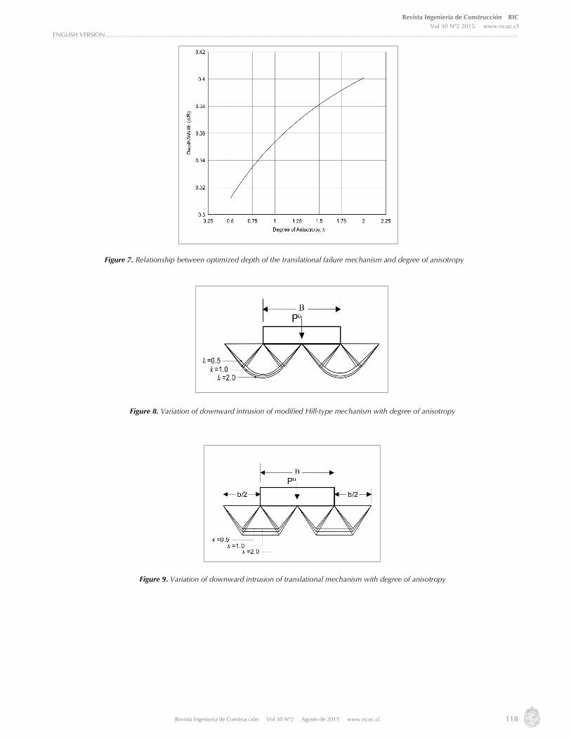
The relationship between the degree of anisotropy k and each of the angle β found from Equation 13b and the depth d obtained from Equation 22 is shown in Figure 6 and Figure 7, respectively. It can be seen that the larger is the degree of soil anisotropy the larger is the angle β and depth d, and hence the lower boundary of the failure mechanisms extend deeper in the ground. This is schematically demonstrated in Figure 8 and Figure 9 for the modified Hill-type mechanism and translational mechanism, respectively. However, the change in downward intrusion when k value increased was larger for the translational mechanism than for the modified Hill-type mechanism.
It is also noticed from Figure 6 that for k ranging from 0.5 to 2 the angle β lies in a narrow range of about 41° – 48.2°. The corresponding values for the term sin 2β increased only from 0.990 to 0.994, a change of about 0.4%. Thus the term sin 2β in Equation 13b can virtually be set equal to one, and hence the angle β is explicitly expressed as
⎥⎦
⎤⎢⎣
⎡ +≅ −
ψψ
βk)cos2-(1
)cos2 k)-(1-k)(1tan21 1
(26)
Figure 5. Discrepancy between the bearing capacity factors and as a function of degree of anisotropy
Figure 6. Relationship between the optimized angle β defining the modified Hill-type failure mechanism and degree of anisotropy
Revista Ingeniería de Construcción RIC Vol 30 Nº2 2015 www.ricuc.cl
ENGLISH VERSION…………......................................................................................................................................................................................................................................
Revista Ingeniería de Construcción Vol 30 Nº2 Agosto de 2015 www.ricuc.cl 118
Figure 7. Relationship between optimized depth of the translational failure mechanism and degree of anisotropy
Figure 8. Variation of downward intrusion of modified Hill-type mechanism with degree of anisotropy
Figure 9. Variation of downward intrusion of translational mechanism with degree of anisotropy
Revista Ingeniería de Construcción RIC Vol 30 Nº2 2015 www.ricuc.cl
ENGLISH VERSION…………......................................................................................................................................................................................................................................
Revista Ingeniería de Construcción Vol 30 Nº2 Agosto de 2015 www.ricuc.cl 119
The values for acMN as obtained from Equation 15
with the angle β given by Equation 26 are listed in column 3 of Table 1. It is noted that for all considered values of
degree of anisotropy, the values for acMN in columns 2 and
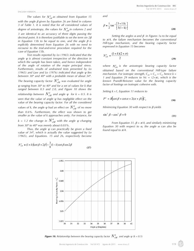
3 are identical to an accuracy of three digits passing the decimal point. It is therefore justifiable to set the term sin 2β in Equation 13b to be equal to one, and the angle β is explicitly determined from Equation 26 with no need to recourse to the trial-and-error procedure required for the case of Equation 13b. Test results reported by Lo (1965) indicated that the angle ψ is almost constant irrespective of the direction in which the sample has been taken, and hence independent of the angle of rotation of the major principal stress. Furthermore, results of undrained tests presented by Lo (1965) and Law and Lo (1976) indicated that angle ψ lies between 30° and 40° with a probable mean of about 34°.
The bearing capacity factor acMN
was evaluated for angle
ψ ranging from 30° to 40° and for a set of values for k that ranged between 0.5 and 2.0, and Figure 10 shows the
relationship between acMN and angle ψ for k = 0.5. It is
seen that the value of angle ψ has negligible effect on the value of the bearing capacity factor. For all the considered
values of k, the angle ψ had an effect on acMN of no more
than 0.6%. Furthermore, the effect was shown to get smaller as the value of k approaches unity. For instance, for
k = 1.2 the change in acMN
with the angle ψ changing
from 30° to 40° was merely about 0.03%. Thus, the angle ψ can practically be given a fixed value of 34°, which is actually the value suggested by Lo (1965), and Equations. 15 and 26, respectively become
( ) ββββ 2coscot)1(832cot)1( kkN a
cM −−++≅ (27)
and
⎥⎦
⎤⎢⎣
⎡
−
+≅ −
k)3(111k 5tan
21 1β
(28) Setting the angles α and β in Figures 1a to be equal to π/4, the failure mechanism becomes the conventional Hill-type mechanism, and the bearing capacity factor expressed in Equation 15 becomes
2)2)(1( π++
=kN a
cH (29)
where NCH
a is the anisotropic bearing capacity factor
obtained based on the conventional Hill-type failure mechanism. For isotropic strength, Cuh = Cuv = Cu, hence k = 1 and Equation 29 reduces to Nc = (2+π), which is the known Prandtl-Reissner value for the bearing capacity factor of footings on isotropic cohesive soils. Setting k =1, Equation 11 reduces to
[ ] uu CBP )(2cotcot βααβ +++= (30)
Minimizing Equation 30 with respect to β yields
0cossin 22 =− ββ (31) From Equation 31, β = π/4, and similarly minimizing Equation 30 with respect to α, the angle α can also be found equal to π/4.
Figure 10. Relationship between the bearing capacity factor and angle ψ (k = 0.5)
Revista Ingeniería de Construcción RIC Vol 30 Nº2 2015 www.ricuc.cl
ENGLISH VERSION…………......................................................................................................................................................................................................................................
Revista Ingeniería de Construcción Vol 30 Nº2 Agosto de 2015 www.ricuc.cl 120
Therefore, it is shown herein that the least bearing capacity of footings on isotropic soils obtained from the modified Hill-type mechanism (Figure 1a) is when the angles α and β in Figure 1a are both equal to π/4 (i.e. the conventional Hill-type mechanism). Certainly, a good upper bound to the true limit load is known to be obtained by considering a collapse mechanism where the geometric parameters are variable. As the process of optimization of the geometry of the failure mechanism is eliminated, the overestimation of the true limit load is expected. However, the results of Table 1 shows that the discrepancy between
the values ofacMN and
acHN is minimal if not negligible,
especially for lower values of k. Indeed, comparison of the data in columns 2 and 4 of Table 1 shows that whether the angle β is varied in an optimization scheme or set a priori at a fixed value of π/4, the discrepancy in the value of the bearing capacity factor does not exceed about 0.4%. Thus the improvement in Pu does not warrant the finding of angle β from Equation 26. Instead it can be set equal to π/4, based not only on the premise that this value for β gives the least upper bound for the case of isotropic strength but also after considering the rather infinitesimal discrepancy between the bearing capacity factor values shown in columns 2 and 4 of Table 1. 3.1 Comparative Study Irrespective of the degree of soil anisotropy, Equation 29 provides upper-bound values that are less than the corresponding values obtained from the translational mechanism (i.e. Equation 25) and only slightly higher than the values provided by the exact solution (i.e. Equation 15), and hence this formula is exclusively used in subsequent discussions.
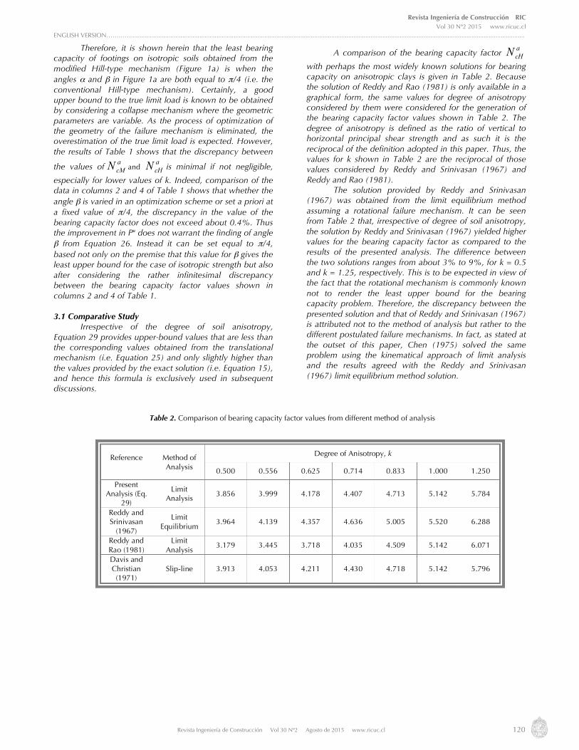
A comparison of the bearing capacity factor acHN
with perhaps the most widely known solutions for bearing capacity on anisotropic clays is given in Table 2. Because the solution of Reddy and Rao (1981) is only available in a graphical form, the same values for degree of anisotropy considered by them were considered for the generation of the bearing capacity factor values shown in Table 2. The degree of anisotropy is defined as the ratio of vertical to horizontal principal shear strength and as such it is the reciprocal of the definition adopted in this paper. Thus, the values for k shown in Table 2 are the reciprocal of those values considered by Reddy and Srinivasan (1967) and Reddy and Rao (1981). The solution provided by Reddy and Srinivasan (1967) was obtained from the limit equilibrium method assuming a rotational failure mechanism. It can be seen from Table 2 that, irrespective of degree of soil anisotropy, the solution by Reddy and Srinivasan (1967) yielded higher values for the bearing capacity factor as compared to the results of the presented analysis. The difference between the two solutions ranges from about 3% to 9%, for k = 0.5 and k = 1.25, respectively. This is to be expected in view of the fact that the rotational mechanism is commonly known not to render the least upper bound for the bearing capacity problem. Therefore, the discrepancy between the presented solution and that of Reddy and Srinivasan (1967) is attributed not to the method of analysis but rather to the different postulated failure mechanisms. In fact, as stated at the outset of this paper, Chen (1975) solved the same problem using the kinematical approach of limit analysis and the results agreed with the Reddy and Srinivasan (1967) limit equilibrium method solution.
Reference
Method of Analysis
Degree of Anisotropy, k
0.500 0.556 0.625 0.714 0.833 1.000 1.250
Present Analysis (Eq.
29)
Limit Analysis
3.856 3.999 4.178 4.407 4.713 5.142 5.784
Reddy and Srinivasan
(1967)
Limit Equilibrium
3.964 4.139 4.357 4.636 5.005 5.520 6.288
Reddy and Rao (1981)
Limit Analysis
3.179 3.445 3.718 4.035 4.509 5.142 6.071
Davis and Christian (1971)
Slip-line 3.913 4.053 4.211 4.430 4.718 5.142 5.796
Table 2. Comparison of bearing capacity factor values from different method of analysis
Revista Ingeniería de Construcción RIC Vol 30 Nº2 2015 www.ricuc.cl
ENGLISH VERSION…………......................................................................................................................................................................................................................................
Revista Ingeniería de Construcción Vol 30 Nº2 Agosto de 2015 www.ricuc.cl 121
Reddy and Rao (1981) used the kinematic approach of limit analysis and adopted Prandtl-type failure mechanism. It is seen from Table 2 that for degree of anisotropy less than one, the presented solution over-predicted the Reddy and Rao (1981) solution, with the deviation being 21% for k = 0.5 and it consistently decreases to reach about 4.5% for k = 0.833. However, as k value becomes greater than one, it is seen that the presented analysis yielded a lower value for the bearing capacity factor. Although no results were available for k value greater than 1.25, the over-prediction of Reddy and Rao (1981) solution is expected to consistently increase with increasing k value. In addition, although the Reddy and Rao (1981) solution provided lower values for the bearing capacity factor in the cases when k is less than one, still however the small improvement is out-weighed by the complexity of the optimization procedure needed to get the least upper bound compared to the simple expression for
acHN provided by Equation 29.
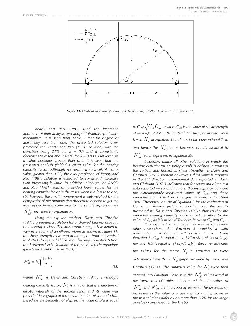
Using the slip-line method, Davis and Christian (1971) presented a solution for undrained bearing capacity on anisotropic clays. The anisotropic strength is assumed to vary in the form of an ellipse, where as shown in Figure 11, the shear strength measured at an angle i from the vertical is plotted along a radial line from the origin oriented 2i from the horizontal axis. Solution of the characteristic equations gave (Davis and Christian 1971):
⎟⎠
⎞⎜⎝
⎛ +=
21/ kNN c
acD
(32)
where acDN is Davis and Christian (1971) anisotropic
bearing capacity factor,
/cN is a factor that is a function of
elliptic integrals of the second kind, and its value was provided in a graphical form as a function of the ratio b/a. Based on the geometry of ellipses, the value of b/a is equal
to Cu45/ uvuhCC , where Cu45 is the value of shear strength
at an angle of 45º to the vertical. For the special case when
b = a, /cN in Equation 32 reduces to the conventional 2+π,
and hence the acDN factor becomes exactly identical to
acHN factor expressed in Equation 29.
Evidently, unlike all other solutions in which the bearing capacity for anisotropic soils is defined in terms of the vertical and horizontal shear strengths, in Davis and Christian (1971) solution however a third value is required in the 45° direction. Experimental data reported in Davis and Christian (1971) indicated that for seven out of ten test data reported by several authors, the discrepancy between the experimentally measured values of Cu45 and those predicted from Equation 3 ranged between 2 to about 10%. Therefore, the use of Equation 3 for the evaluation of Cu45
is considered justifiable. Furthermore, the results presented by Davis and Christian (1971) showed that the predicted bearing capacity value is not sensitive to the value of Cu45 as it is to the differences between Cuh and Cuv. It is assumed in this paper, as well as by several other researchers, that Equation 3 provides a valid representation of shear strength in any direction. From Equation 3, Cu45 is equal to (1+k)Cuv/2, and accordingly
the ratio b/a is equal to (1+k)/(2 k ). Based on this ratio
the values for the factor /cN in Equation 32 were
determined from the k-/cN graph provided by Davis and
Christian (1971). The obtained value for /cN were then
entered into Equation 32 to give the acDN values listed in
the fourth row of Table 2. It is noted that the values of acHN and
acDN
are in a good agreement. The discrepancy
increased as the value of k deviates from unity; however the two solutions differ by no more than 1.5% for the range of values considered for the k ratio.
Figure 11. Elliptical variation of undrained shear strength (After Davis and Christian, 1971)

Revista Ingeniería de Construcción RIC Vol 30 Nº2 2015 www.ricuc.cl
ENGLISH VERSION…………......................................................................................................................................................................................................................................
Revista Ingeniería de Construcción Vol 30 Nº2 Agosto de 2015 www.ricuc.cl 122
As far as the locus of strength is assumed to be represented by Equation 3, the change in the b/a ratio with k is, as shown in Figure 12, considered small. The corresponding change in the value of /
cN with respect to
the ratio b/a, and hence k, was found to be further minimal. For instance, for a value of 1 and 2 for the ratio k the corresponding values for the factor /
cN are 5.14 and
4.95, respectively. Thus a change of 100% in the value of k resulted merely in about 3.7% change in the value of /
cN .
Therefore, the factor /cN can approximately be assumed to
be independent of k and thus given a fixed value of 2+π. Consequently the bearing capacity factor a
cDN obtained
from a slip-line method solution and expressed in Equation 32 becomes exactly identical to the factor a
cHN provided in
Equation 29 which was derived based on the upper bound approach. Actually, Davis and Christian (1971) suggested that in the absence of Cu45 value the factor /
cN in Equation 32 is
to be replaced by χ(2+π), where χ is a correction factor. The experimental data compiled by Davis and Christian (1971) indicated that the value of χ ranges between 0.89 to 1.03, the average value being 0.97. They suggested the use of χ = 0.9, and accordingly for a given degree of anisotropy the value of a
cDN is 10% less than the corresponding value
of acHN . This is justifiable if we remember that a
cHN is in fact
an upper bound solution.
It is therefore interesting to notice that the upper bound solution derived in this paper for the case of the conventional Hill-type failure mechanism and the slip-line method solution presented by Davis and Christians (1971) yield identical expressions for the anisotropic bearing capacity factor, provided that in the Davis and Christian (1971) solution, either the angular variation of shear strength is defined as in Figure 11 but the b/a ratio is set equal to 1, or alternatively the Casagrande and Carillo (1944) relationship (i.e. Equation 3) is considered valid and the dependency of the ratio b/a on the value of k is assumed negligible. Whether the ratio b/a is set equal to one or evaluated as (1+k)/(2 k ), the loci of strength distribution for the two cases are reasonably comparable as shown in Figure 11.
Figure 12. b/a ratio versus degree of anisotropy with the strength distribution represented by Casagrande and Carillo formula

Revista Ingeniería de Construcción RIC Vol 30 Nº2 2015 www.ricuc.cl
ENGLISH VERSION…………......................................................................................................................................................................................................................................
Revista Ingeniería de Construcción Vol 30 Nº2 Agosto de 2015 www.ricuc.cl 123
4. Summary and conclusions Employing the kinematical approach of limit analysis method, this paper presents closed-form solutions for the undrained bearing capacity of shallow strip footings on anisotropic clays. The solutions were obtained using modified Hill-type and translational failure mechanisms with variable wedge angles. The derived expressions make it possible to analytically and straightforwardly calculate the bearing capacity of anisotropic clays, in comparison with other available solutions in which results are mostly presented in the form of graphs and tables for discrete values of soil and failure mechanism parameters. The influence of degree of soil anisotropy on the value for the bearing capacity factor was investigated for the attempted mechanisms as well as through comparison with pertinent results of other investigations. Although the use of the modified Hill-type mechanism has provided an analytical expression for the bearing capacity factor a
cMN (Equation 15), however the
angle β defining the mechanism need to be found from a trial-and-error procedure (Equation 13b). It was found, however, that for a wide range of degree of anisotropy the corresponding range for the possible values for angle β is very narrow. Thus, the angle β can conveniently be determined from the approximate analytical expression given into Equation 26 without recourse to the trial-and-error procedure required by the exact solution expressed in Equation 13b. The results of the parametric study has also shown that for a given degree of soil anisotropy, whether the angle β is varied in an optimization scheme or given a fixed value of π/4, the corresponding values for the bearing capacity factor are very comparable. Thus the improvement in the predicted upper bound for a
cMN does not warrant the use of
the modified Hill-type mechanism with variable wedge angle. Instead, the conventional Hill-type failure mechanism with β = π/4 can reasonably provide not only analytical solution (i.e. Equation 29) but also an expression for the bearing capacity factor,
acHN that is explicit,
concise, and simple for use in practical applications. In addition, although the deviation between the upper bound values obtained from the two mechanisms is considered well within acceptable limits for practical applications, still the conventional Hill-type mechanism with no optimization of geometric parameters provides a
cHN values that are less
than the optimized acTN values associated with the
translational failure mechanism. It was interesting to find out that the a
cHN is exactly
equal to the conventional Prandtl-Reissner bearing capacity factor for the case of isotropic soil (i.e. 2+π) multiplied by the average of the sum of degree of anisotropy plus unity. In other word, the bearing capacity of footings on anisotropic clays is simply obtained from conventional analysis with the isotropic shear strength value being replaced by the average value of the shear strength in the vertical and horizontal directions. Assuming that the variation of shear strength with direction is justifiably represented by the Casagrande and Carillo formula (Equation 3), the upper bound values for the bearing capacity factor obtained from the modified Hill-
type mechanism (Equation 15) were found practically identical to the values obtained from the Davis and Christian’s slip-line method solution (Equation 32). The discrepancy between the two solutions increased as the degree of anisotropy deviates from unity, however the two solutions differed by no more than 1.5% for values of degree of anisotropy, k, ranging between 0.5 and 2.0. It was further found that the upper bound solution arrived at in this paper, for the case of the conventional Hill-type failure mechanism (Equation 29), and the slip-line method solution presented by Davis and Christian yield identical bearing capacity factors provided that in the slip-line method solution the elliptical distribution of shear strength shown in Figure 11 is approximated by a circular distribution (i.e. b = a), or alternatively taken to be represented by the Casagrande and Carillo distribution but the dependency of the ratio b/a on the value of degree of anisotropy is assumed negligible.
Revista Ingeniería de Construcción RIC Vol 30 Nº2 2015 www.ricuc.cl
ENGLISH VERSION…………......................................................................................................................................................................................................................................
Revista Ingeniería de Construcción Vol 30 Nº2 Agosto de 2015 www.ricuc.cl 124
5. Nomenclature B: Width of foundation Cuh: Undrained shear strength corresponding to horizontal direction at surface Cui: Undrained shear strength at inclination i of major principal stress with vertical Cun: Undrained shear strength along failure plane n Cuv: Undrained shear strength corresponding to vertical direction at surface Cu45: Undrained shear strength at an angle of 45o to the vertical d: Downward extension of failure mechanism h: Lateral extension of failure mechanism I
: Inclination of the major principal stress with vertical
direction K: Coefficient of anisotropy ln: Length
of failure plane n
n: Integer acDN : Davis and Christian anisotropic bearing capacity
factor acHN : Anisotropic bearing capacity factor associated with
the conventional Hill-type failure mechanism acMN : Anisotropic bearing capacity factor associated with
the modified Hill-type failure mechanism
acTN : Anisotropic bearing capacity factor associated with
the translational failure mechanism /cN : A factor in Davis and Christian anisotropic bearing
capacity factor qu: Ultimate bearing capacity Pu: Ultimate load R: Radius of slip fan in the modified Hill-type failure mechanism Vf: Displacement of foundation Vn: Displacement along failure plane n α, β: Geometric parameters for the modified Hill-type failure mechanism ζ, η
:: Geometric parameters for the translational failure
mechanism δE: Rate of external work δW: Rate of internal energy dissipation δWn: Rate of internal energy dissipation along failure plane n θ: Geometric parameter ψ: Angle between major principal stress and failure plane
6. References Bishop A., W. (1966), The strength of soils as engineering materials”, Geotechnique. 16(1), 85-128. Casagrande A. and Carillo N. (1944), Shear failure of anisotropic materials. Contribution to Soil Mech., Boston Soc. of Civ. Engineers. 122-135. Chen W., F. (1975), Limit Analysis and Soil Plasticity. Elsevier, Amsterdam. Chen W., F. and Davidson H., L. (1973), Bearing capacity determination by limit analysis. Journal of the Soil Mechanics and Foundation
Division. 99(6), 433-449. Chen W., F. and Giger M., W. (1971), Limit analysis of stability of slopes. Journal of the Soil Mechanics and Foundation Division. 97(SM1), 19-
26. Chen W., F. and Rosenfarb J., L. (1973), Limit analysis solutions of earth pressure problems. Soils and Foundations. 13(4), 45-60. Davis E., H. and Christian J., T. (1971), Bearing capacity of anisotropic cohesive soils. Journal of the Soil Mechanics and Foundation Division.
97(SM5), 753-769. Drescher A. (1983), Limit plasticity approach to piping in bins. Journal of Applied Mechanics. 50, 549-553. Drucker D., C. (1991), Constitutive relations for solids retrospect and prospect. In the proceedings of 3rd Inl. Conf. on Constitutive laws for
Engineering Materials, Tucson, Arizona. 199, 3-12. Drucker D., C., Greenberg H., J. and Prager W. (1952), Extended limit design theorems for continuous media. Quarterly Journal of Applied
Mathematics. 9, 381-389. Florkiewicz A. (1989), Upper bound to bearing capacity of layered soils. Canadian Geotechnical Journal. 26(4), 730-736. Izbicki R., J. (1981), Limit plasticity approach to slope stability problems. Journal of Geotechnical Engineering. 107(2), 228-233. Kumar J. and Khatri V., N. (2011), Bearing capacity factors of circular foundations for a general c – ø soil using lower bound finite elements
limit analysis. International Journal for Numerical and Analytical Methods in Geomechanics. 35(3), 393–405. Kumar J. and Kouzer K. (2007), Effect of Footing Roughness on Bearing Capacity Factor Nγ. Journal of Geotechnical and Geoenvironmental
Engineering. 133(5), 502-511. Kumar J. and Kouzer K. (2008a), Bearing Capacity of Two Interfering Footings. International Journal for Numerical and Analytical Methods in
Geomechanics. 32, 251–264. Kumar J. and Kouzer K. (2008b), Vertical Uplift Capacity of Horizontal Anchors using Upper Bound Limit Analyses and Finite Elements.
Canadian Geotechnical Journal. 45, 698-704. Law K., T. and Lo K., Y. (1976), Analysis of shear-induced anisotropy in Leda-Clay. In the Proceedings of Conference on Numerical Methods in
Geomechanics, Blacksburg, VA. 329-344. Lee K., M. and Rowe R., K. (1989), Effects of undrained strength anisotropy on surface subsidences induced by the construction of shallow
tunnels. Canadian Geotechnical Journal. 26, 279-291. Livneh M. and Komornik A. (1967), Anisotropic strength of compacted clays. In the proceedings of 3rd Asian Regional Conference on Soil
Mechanics and Foundation Engineering. 298-304. Lo K. Y. (1965), Stability of slopes in anisotropic soils. Journal of the Soil Mechanics and Foundation Division. 31(SM4), 85-106. Menzies B. K. (1976), An approximate correction for the influence of strength anisotropy on conventional vane shear measurements used to
predict field bearing capacity. Geotechnique. 26, 631-634. Michalowski R. L. (1997), An estimate of the influence of soil weight on bearing capacity using limit analysis. Soils and Foundations. 37(4), 57-
64.

Revista Ingeniería de Construcción RIC Vol 30 Nº2 2015 www.ricuc.cl
ENGLISH VERSION…………......................................................................................................................................................................................................................................
Revista Ingeniería de Construcción Vol 30 Nº2 Agosto de 2015 www.ricuc.cl 125
Reddy A. S. and Rao K., N. V. (1981), Bearing capacity of strip footing on anisotropic and nonhomogeneous clays. Soils and Foundations. 21(1), 1-6.
Reddy A. S. and Srinivasan R. J. (1967), Bearing capacity of footings on layered soils. J of the Soil Mechanics and Foundation Division. 93(SM2), 83-99.
Sloan S.W. (1988), Lower bound limit analysis using finite elements and liner programming. International Journal for Numerical and Analytical Methods in Geomechanics. 12, 61-77.
Su S. F., Liao H. J. and Lin Y. H. (1998), Base stability in anisotropic soft clay. Journal of Geotechnical and Geoenvironmental Engineering. 124, 809-819.
Ukritchon B. B., Whittle A. and Sloan S.W. (1998), Undrained limit analyses for combined loading of strip footings on clay. Journal of Geotechnical Engineering. 124(3), 265-276.
Ward H.W., Marsland A. and Samuels S.G. (1965), Properties of the London clay at the Ashford Common Shaft: In-situ and undrained strength tests. Geotechnique. 15(4), 321-349.