
Strip. Que quieres quitarme? Que me pongo? Que quieres quitarme?

MANUFACTURER: Integra NeuroSciences Implants (France) S.A.S.2905 Route des Dolines 06921 SOPHIA ANTIPOLIS CEDEX, FRANCE
Integra®
BL405007-04
Cortical Strip & Grid ElectrodesElectrodes corticales : bandes et grillesKortikale Streifen & GitterelektrodenElettrodi per area Corticale a Striscia & A GrigliaElectrodos Corticales de Banda y de RejillaCorticale Strip & Rooster elektroden
Instructions for UseMode d’EmploiGebrauchsanleitungIstruzioni per l’UsoInstrucciones de UsoGebruiksinstructies
Auragen™

2
DESCRIPTION
The AURAGEN™ Cortical Surface Electrodes are designed for intraoperative monitoring of cortical electrical activity in order to define the location of epileptogenic foci. They are placed on the exposed cortical surface or inserted into the subdural space to contact the cortical surface.
Cortical Electrodes vary in size according to the number of contacts. The type of cortical electrode used is dependent on the procedure and the size of area being tested.
The Auragen Cortical Electrodes are available with platinum/iridium contacts, with 2 to 64 contacts. Electrodes have Standard 4.75 mm diameter contacts with 1.5 mm contact exposure minimum and 1 cm spacing between the centers to center. The grid electrode number 1 contacts are marked with tantalum, to enhance radiopacity so that, if necessary, the physician can distin-guish the number 1 contact under X-ray. The electrode connectors are designed and fabricated as subminiature Cylindrical Connectors, with gold-plated contact rings.
The leads (except branched leads) can be tunnelized through a needle with an inner diameter over 1.9mm.
Materials with patient contact are platinum/iridium, silicone elastomer and black silicone ink.
Auragen Strip Electrodes marking & color coding:
English
Type : 2 contactsType : 4 contactsType : 6 contactsType : 8 contactsType: 10 contactsType: 12 contacts
-Yellow
BlueRed
GreenOrange
Random colorRandom color Random color Random color Random colorRandom color
White with numberWhite with numberWhite with numberWhite with numberWhite with numberWhite with number
Numbers of contacts First band Second band Third band
Random color
First band
White with number and black dots (to number leads 1 up to 8)
Second band
Auragen Grid Electrodes marking & color coding:

3
English
Electrode Connecting Cables
The Integra Auragen Electrodes are designed to be used with the Integra Connecting Cables. The Cables are made with varying numbers of female pins to fit with the existing strip or grid electrodes.
Connecting Cables are designed to create an easy-to-use, reliable interface between Integra Auragen Electrodes and most EEG Monitoring Systems. These cables feature gold-plated contact pins and connector contacts, with insulated 28 gauge copper ribbon cable for maximum sensitivity and low impedance.
Note: Cables are sold non sterile. Should sterilization be desired, the cables may be sterilized at low temperature gas plasma. Sterilization was validated with Sterrad 100S Sterilization System (Advanced Sterilization Products) up to 10 sterilization cycles. The cycle comprised two iden-tical exposure phases: 6 min injection, 2 min diffusion and 2 min plasma preceeded by a 10 min pre-exposure plasma phase.
Please refer to the Integra Electrode Connecting Cables Instructions for Use.
INDICATIONS
The Auragen Cortical Surface Electrodes are intended for the intraoperative recording of EEG signals at the cortical surface of the brain.
CONTRAINDICATIONS
These electrodes should not be inserted into any patient who has an active infection (meningitis, ventriculitis, skin infections, etc.), or who has recently had a scalp laceration.
SIDE EFFECTS
Possible complications include: infection, CSF leak, neurological complications, hemorrhage, pain, mechanical or electrical fai-lure.
WARNINGS:• Electrodes are for single use only and should not be re-sterilized or re-used after removal to avoid the transmission of
Creutzfeldt-Jakob disease by intracranial electrodes.• Placement in patients with an active CSF leak or CSF Drainage System is not recommended.• Reminder: Use great caution in the operating room. Ensure adequate support of equipment and staff.• Reminder: Remove electrodes in the operating room, as removal remains a critical part of the procedure.
• Not intended as an implant but for intraoperative use only.
PRECAUTIONS
• The electrode leads are fragile and must be handled with extreme care.• Storage and Transport: The Electrodes may be stored at room temperature. They will withstand the conditions of normal
transport. • This product is for single use only. Do not reuse. • This product is sterilized with ethylene oxide. Do not use if the package is open or damaged. Use the device prior to the
«Use by» date on the package label.Caution - Do not resterilize. Integra will not be liable for any or all damages including, but not limited to, direct, indirect, incidental, consequential or punitive damages resulting from or related to resterilization.

English
4
SUGGESTED PROCEDUREPlacement of the Cortical Electrodes may be accomplished through a variety of surgical techniques. The surgeon is advised to use a surgical technique according to his/her standard practice.
Inserting Connector Cable Pins into an EEG Monitor1. The Connector Cables have up to 64 gold plated Connector Pins numbered 1 up to 64 that correspond to the Electrode
Contacts 1 up to 64 when the Electrode and Cable are joined properly (see Sections 2 & 3). These pins are to be plugged into the corresponding EEG Monitor input channels (see EEG Monitor Manufacturer’s Instructions).
Inserting a Cylindrical Strip Electrode Connector into a Cable Connector2a. Align either of two white locator dots on the cable connector thumb screw with the dot on the top of the cable connector
block (Fig. A).
2b. With the cable connector in the “LOAD” position, insert the electrode connector into the hole located opposite the thumb screw. Visually confirm electrode/cable contact alignment through the top of the connector cap (the tip electrode contact should align with the first pair of gold contacts on the thumb screw end of the cable connector) (Fig. B).
2c. Lock the electrode in place by turning the thumb screw in either direction until a distinct click is felt. The locator dots will now rest in the horizontal position (Fig. C). When the electrode is properly placed and the thumb screw is in the horizontal lock position, a locking mechanism is engaged to prevent accidental separation of the two components.
Inserting Cylindrical Grid Electrode Connectors into Cable Connectors3a. Grid Electrodes have multiple Connectors and must be attached to a Connecting Cable with enough contacts to accom-
modate those connectors.
3b. Grid Electrode Connectors are inserted into Cable Connectors in the same manner that Strip Electrode Connectors are inserted into a Cable Connector (see Section 2: a, b, c) with one stipulation. Because there is more than one lead coming from a single Grid Electrode, the leads are numbered 1 up to 8 by 1 up to 8 dots (depending on the type of Grid) and should be connected to the corresponding numbered cable connector (Fig. D ). This is critical in order to achieve continuity between specific electrode contacts and EEG Monitor Channels.
4. Remove electrodes in the operating room in accordance with accepted surgical procedure or the surgeon’s standard practice.
Fig. A
Fig. B
Fig. C
Fig. D
English
5
Date of revision: June 2014
HOW SUPPLIEDIntegra Auragen Cortical Surface Electrodes are supplied sterile and non-pyrogenic in a double-wrap packaging.
DisposalAfter patient use, the device must be handled as biohazardous material and disposed of in accordance with applicable Federal State, local, or international environmental requirements following facility protocols.
PRODUCT INFORMATION DISCLOSUREINTEGRA HAS EXERCISED REASONABLE CARE IN THE CHOICE OF MATERIALS AND MANUFACTURE OF THIS PRODUCT. INTE-GRA EXCLUDES ALL WARRANTIES, WHETHER EXPRESSED OR IMPLIED BY OPERATION OF LAW OR OTHERWISE, INCLUDING BUT NOT LIMITED TO, ANY IMPLIED WARRANTIES OF MERCHANTABILITY OR FITNESS FOR A PARTICULAR PURPOSE. INTEGRA SHALL NOT BE LIABLE FOR ANY INCIDENTAL OR CONSEQUENTIAL LOSS, DAMAGE, OR EXPENSE, DIRECTLY OR INDIRECTLY ARISING FROM USE OF THIS PRODUCT. INTEGRA NEITHER ASSUMES NOR AUTHORIZES ANY PERSON TO ASSUME FOR IT ANY OTHER OR ADDITIONAL LIABILITY OR RESPONSIBILITY IN CONNECTION WITH THESE PRODUCTS. INTEGRA INTENDS THAT THIS DEVICE SHOULD BE USED ONLY BY PHYSICIANS WITH EDUCATIONAL AND TRAINING BACKGROUND ENABLING THE PROPER USE OF THE DEVICE.
Returned Goods PolicyAuthorization from customer service must be obtained prior to returning product.Sterile products must be returned in unopened packages with manufacturer’s seals intact to be accepted for replacement or credit unless returned due to a complaint or product defect.Determination of a product defect will be made by Integra.Credit will be issued for goods returned prior to 90 days from ship date and may be subject to a restocking charge of up to 20%. This assumes that the product returned is not damaged and can be verified to have not been used or opened.
Product Order InformationAll products can be ordered through your Integra NeuroSpecialist or customer service representative or by contacting:
Integra LifeSciences Corporation311 Enterprise DrivePlainsboro, NJ 08536, U.S.A.Telephone: 1-800-654-2873Outside the US: +1-609-275-0500Fax: +1-609-275-5363
Integra NeuroSciences Implants (France) S.A.S.2905 Route des Dolines06921 Sophia Antipolis CEDEX, FranceTelephone: +33 (0) 4 93 95 56 00Fax: +33 (0) 4 93 65 40 30
Integra LifeSciences Services (France)Immeuble Séquoia 297 allée Alexandre BorodineParc Technologique de la Porte des Alpes69800 Saint Priest, FranceTelephone: +33 (0) 4 37 47 59 00Fax: +33 (0) 4 37 47 59 99
Français
6
DESCRIPTIONLes électrodes corticales AURAGEN™ sont conçues pour un monitoring per-opératoire de l’activité électrique corticale pour localiser les zones épileptogènes. Elles sont placées sur la surface corticale exposée ou insérées dans l’espace sous-dural.
La taille des électrodes corticales varie selon leur nombre de contacts. Le choix du type d’électrode dépend de la procédure et de la taille de la zone à tester.
Les électrodes corticales Auragen ont 2 à 64 contacts en platine/iridium. Les contacts standard font 4,75mm de diamètre, avec une zone de contact de 1,5mm minimum. Les centres de deux contacts adjacents sont espacés de 1 cm.
Les contacts numéro 1 des Grilles corticales sont marqués au tantale, pour augmenter leur radio-opacité pour que, si nécessaire, le médecin puisse distinguer le contact numéro 1 lors d’une radiographie.
Les électrodes ont des connecteurs cylindriques miniaturisés avec des contacts plaqués or.
Les branches (sauf dans le cas de branches divisées) peuvent être tunnellisées dans une aiguille de diamètre intérieur supérieur à 1.9mm.
Les matériaux en contact patient sont : le platine/iridium, l’élastomère de silicone et l’encre silicone noire.
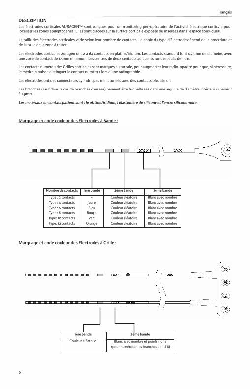
Marquage et code couleur des Electrodes à Bande :
Type : 2 contactsType : 4 contactsType : 6 contactsType : 8 contactsType: 10 contactsType: 12 contacts
-JauneBleu
RougeVert
Orange
Couleur aléatoire Couleur aléatoireCouleur aléatoireCouleur aléatoireCouleur aléatoireCouleur aléatoire
Blanc avec nombreBlanc avec nombreBlanc avec nombreBlanc avec nombreBlanc avec nombreBlanc avec nombre
Nombre de contacts 1ère bande 2ème bande 3ème bande
Couleur aléatoire
1ère bande
Blanc avec nombre et points noirs (pour numéroter les branches de 1 à 8)
2ème bande
Marquage et code couleur des Electrodes à Grille :

Français
7
Câbles de connexion pour les électrodesLes électrodes Integra Auragen sont conçues pour être utilisées avec les câbles Integra. Les câbles sont disponibles avec un nombre variable de fiches femelles, adapté aux électrodes à bande ou grille Integra.
Les câbles Integra sont conçus pour créer une interface fiable et facile à utiliser, entre les électrodes Integra et la plupart des systèmes de monitoring d’EEG. Ces câbles ont des contacts et des fiches plaqués or, et une nappe de fils de cuivre isolés, assurant une sensibilité maximale et une faible impédance.
Note : Les câbles sont vendus non stériles. Si la stérilisation des câbles est souhaitée, une stérilisation à basse température par le gaz plasma est possible : elle a été validée avec le Sterrad 100S (Advanced Sterilization Products) jusqu’à 10 cycles. Le cycle validé comprend 10min de préexposition au gaz plasma suivie de 2 cycles identiques (6min d’injection, 2min de diffusion du peroxyde d’hydrogène et 2min de plasma).
Merci de se référer au Mode d’emploi des Câbles de connexion pour électrodes Integra.
INDICATIONSLes électrodes corticales Auragen sont conçues pour l’enregistrement intra-opératoire de signaux EEG à la surface corticale du cerveau.
CONTRAINDICATIONSCes électrodes ne devraient pas être utlisisées en cas d’infection (méningite, ventriculite, infections cutanées, etc), ou en cas de blessure récente du cuir chevelu.
EFFETS SECONDAIRESLes complications possibles incluent : infection, fuite de LCR, complications neurologiques, hémorragie, douleur, complication mécanique ou électrique.
AVERTISSEMENTS:• Les électrodes sont à usage unique et ne devraient pas être re-stérilisées ou réutilisées pour éviter tout risque de transmis-
sion de la maladie de Creutzfeldt-Jakob.
• Il est recommandé de ne pas utiliser les électrodes chez des patients traités par drainage externe de LCR ou présentant une fuite de LCR.
• Rappel : Manipulez avec précaution les électrodes en salle d’opération. Le personnel doit être formé à l’utilisation des produits.
• Rappel : Les électrodes doivent être retirées en salle d’opération, le retrait est une étape critique de la procédure.
• Les électrodes ne sont pas conçues pour rester implantées mais pour une utilisation per-opératoire.
PRECAUTIONS• Les électrodes sont fragiles et doivent être manipulées avec précautions.• Conditions de stockage et transport : Les électrodes peuvent être stockées à température ambiante. Elles résistent aux
conditions normales de transport.• Ce produit est conçu pour un usage unique. Ne pas ré-utiliser. • Ce produit est stérilisé avec de l’oxyde d’éthylène. Ne pas utiliser si l’emballage est ouvert ou endommagé. Utiliser le
produit avant la date limite d’utilisation imprimée sur l’étiquette figurant sur l’emballage.Attention - Ne pas restériliser Integra ne saurait être tenue responsable de tous dommages incluant mais non limités aux dom-mages directs, indirects, consécutifs ou punitifs afférents à la restérilisation.
Français
8
PROCEDURE RECOMMANDEELe placement des électrodes corticales peut être réalisé suivant différentes techniques chirurgicales, laissées à l’appréciation du chirurgien.
Insertion du câble dans un Moniteur d’EEG 1. Les câbles ont jusqu’à 64 fiches plaquées or, numérotées de 1 à 64, correspondant aux contacts 1 à 64 de l’électrode,
lorsque l’électrode et le câble sont correctement connectés (voir Sections 2 & 3). Ces fiches doivent être branchées sur les entrées correspondantes du moniteur d’EEG (se référer au Mode d’emploi du moniteur d’EEG).
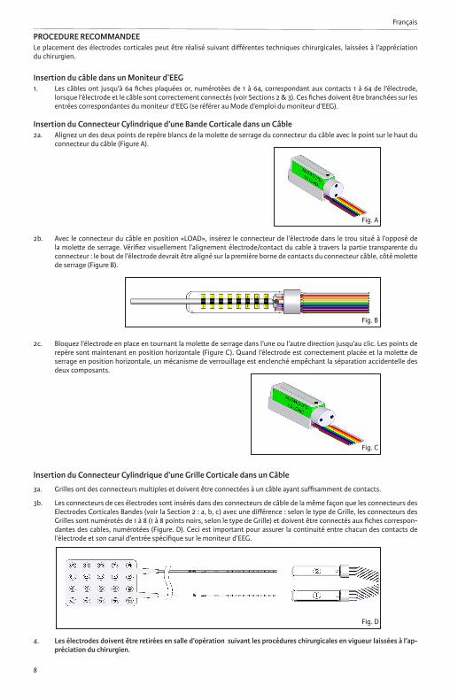
Insertion du Connecteur Cylindrique d’une Bande Corticale dans un Câble2a. Alignez un des deux points de repère blancs de la molette de serrage du connecteur du câble avec le point sur le haut du
connecteur du câble (Figure A).
2b. Avec le connecteur du câble en position «LOAD», insérez le connecteur de l’électrode dans le trou situé à l’opposé de la molette de serrage. Vérifiez visuellement l’alignement électrode/contact du cable à travers la partie transparente du connecteur : le bout de l’électrode devrait être aligné sur la première borne de contacts du connecteur câble, côté molette de serrage (Figure B).
2c. Bloquez l’électrode en place en tournant la molette de serrage dans l’une ou l’autre direction jusqu’au clic. Les points de repère sont maintenant en position horizontale (Figure C). Quand l’électrode est correctement placée et la molette de serrage en position horizontale, un mécanisme de verrouillage est enclenché empêchant la séparation accidentelle des deux composants.
Insertion du Connecteur Cylindrique d’une Grille Corticale dans un Câble
3a. Grilles ont des connecteurs multiples et doivent être connectées à un câble ayant suffisamment de contacts.
3b. Les connecteurs de ces électrodes sont insérés dans des connecteurs de câble de la même façon que les connecteurs des Electrodes Corticales Bandes (voir la Section 2 : a, b, c) avec une différence : selon le type de Grille, les connecteurs des Grilles sont numérotés de 1 à 8 (1 à 8 points noirs, selon le type de Grille) et doivent être connectés aux fiches correspon-dantes des cables, numérotées (Figure. D). Ceci est important pour assurer la continuité entre chacun des contacts de l’électrode et son canal d’entrée spécifique sur le moniteur d’EEG.
4. Les électrodes doivent être retirées en salle d’opération suivant les procédures chirurgicales en vigueur laissées à l’ap-préciation du chirurgien.
Fig. A
Fig. C
Fig. B
Fig. D
PRESENTATIONLes électrodes corticales Auragen Integra sont fournies stériles et apyrogènes, conditionnées en double poche.
EliminationAprès utilisation sur un patient, le dispositif doit être traité comme un matériel biologique dangereux et éliminé conformément aux règlementations fédérales, d‘État, locales ou internationales relatives aux exigences environnementales et selon les proto-coles d’usage.
RENSEIGNEMENTS SUR LES PRODUITSINTEGRA FAIT PREUVE D’UNE ATTENTION PARTICULIÈRE DANS LE CHOIX DES MATÉRIAUX ET DE LA FABRICATION DE CE PRODUIT. INTEGRA EXCLUT TOUTE GARANTIE, EXPLICITE OU IMPLICITE, EN VERTU DE LA LOI OU À TOUT AUTRE TITRE, CE QUI INCLUT, MAIS NE SE LIMITE PAS, AUX GARANTIES IMPLICITES DE CONFORMITÉ ET D’USAGE NORMAL DANS UN BUT PARTICULIER. LA RESPONSABILITÉ D’INTEGRA NE PEUT ÊTRE ENGAGÉE EN CAS DE PRÉJUDICE, DOMMAGE OU EFFET NÉ-FASTE, CONSÉCUTIF OU INDIRECT, RÉSULTANT DIRECTEMENT OU INDIRECTEMENT DE L’UTILISATION DU PRODUIT. INTEGRA N’ASSUME AUCUNE AUTRE RESPONSABILITÉ EN LIEN AVEC CES PRODUITS ET N’AUTORISE AUCUN TIERS À ASSUMER DE TELLES RESPONSABILITÉS EN SON NOM. INTEGRA STIPULE QUE CE DISPOSITIF DOIT ETRE EXCLUSIVEMENT UTILISE PAR DES PRATICIENS DE FORMATION ET D’EXPERIENCE LEUR PERMETTANT UN USAGE CORRECT DU DISPOSITIF.
Renvois des ProduitsAvant tout retour produit, il est nécessaire d’obtenir l’accord du service clients. Pour être acceptés, les produits stériles devront être retournés dans leur emballage non ouvert avec les sceaux du fabricant intacts afin qu’il soit procédé à leur remplacement ou à leur remboursement, à moins que le retour ne soit dû à une réclamation ou à un défaut du produit.Integra se chargera d’apprécier si le produit est défectueux.Seuls les produits retournés sous 90 jours à compter de la date d’expédition seront remboursés et pourront être soumis à des frais de restockage susceptibles d’atteindre 20 % de leur valeur. Cela suppose que le produit renvoyé ne soit pas endommagé et qu’il soit possible de vérifier qu’il n’a été ni utilisé, ni ouvert.
Informations concernant la Commande de ProduitsTous les produits peuvent être commandés par votre représentant Integra NeuroSciences local ou au Service Client ou en contactant :
Integra LifeSciences Corporation311 Enterprise DrivePlainsboro, NJ 08536, U.S.A.Telephone: 1-800-654-2873Outside the US: +1-609-275-0500Fax: +1-609-275-5363
Integra NeuroSciences Implants (France) S.A.S.2905 Route des Dolines06921 Sophia Antipolis CEDEX, FranceTelephone: +33 (0) 4 93 95 56 00Fax: +33 (0) 4 93 65 40 30
Integra LifeSciences Services (France)Immeuble Séquoia 297 allée Alexandre BorodineParc Technologique de la Porte des Alpes69800 Saint Priest, FranceTelephone: +33 (0) 4 37 47 59 00Fax: +33 (0) 4 37 47 59 99
Date de révision: Juin 2014
Français
9

Deutsch
10
BESCHREIBUNGDie kortikalen Oberflächenelektroden AURAGEN™ dienen der Kontrolle der elektrischen kortikalen Aktivität zur Bestimmung des Ortes epileptogener Foci. Sie werden auf der exponierten kortikalen Oberfläche oder im subduralen Raum platziert, um einen Kontakt zur kortikalen Oberfläche herzustellen.
Die Größe der kortikalen Elektroden variiert je nach Anzahl der Kontakte. Welcher Elektrodentyp eingesetzt wird, hängt vom Verfahren und der Größe des Testbereichs ab.
Die kortikalen Auragen-Oberflächenelektroden mit Platin-Iridium-Kontakten sind mit 2 bis 64 Kontakten erhältlich. Der Stan-darddurchmesser der Elektrodenkontakte beträgt 4,75 mm mit einer minimalen Kontakteinwirkung von 1,5 mm und 1 cm Abs-tand zwischen den einzelnen Zentren zum Zentrum. Die Gitterektrodekontakte Nummer 1 enthalten – zur Erhöhung der Radio-pazität – Tantal, damit der Arzt ggf. die Nummer-1-Kontakte im Röntgenbild erkennen kann. Bei den Elektrodensteckverbindern handelt es sich um zylindrische Subminiatur-Steckverbinder mit goldbeschichteten Kontaktringen.
Die Anschlussdrähte (mit Ausnahme von verzweigten Drähten) können mithilfe einer Nadel mit einem Innendurchmesser von 1,9 mm tunneliert werden.
Der Patient kommt mit folgenden Materialien in Kontakt: Platin-Iridium, Silikonelastomer und schwarzer Silikontinte.
Auragen Streifenelektroden-Kennzeichnung & Farbmarkierung :
Kontakttyp : 2 kontaktKontakttyp : 4 kontaktKontakttyp : 6 kontaktKontakttyp : 8 kontakt
Kontakttyp : 10 kontaktKontakttyp : 12 kontakt
-GelbBlauRot
GrünOrange
Verschiedene FarberVerschiedene Farber Verschiedene Farber Verschiedene Farber Verschiedene FarberVerschiedene Farber
Weiß mit ZahlWeiß mit Zahl Weiß mit ZahlWeiß mit ZahlWeiß mit ZahlWeiß mit Zahl
Anzahl Kontakte Erstes band Zweites band Drittes band
Verschiedene Farbe
Erstes band
Weiß mit Zahl und schwarzen Punkten(zur Nummerierung der Drähte 1 bis 8)
Zweites band
Auragen Gitterelektroden -Kennzeichung & und Farbmarkierung :

Deutsch
11
Elektroden-AnschlusskabelDie Integra Auragen-Elektroden sind für die Verwendung mit Integra Verbindungsdrähten konzipiert. Die drähte haben für den Anschluss von bereits vorhandenen Streifen- oder Rasterlektroden unterschiedlich viele weibliche Buchsen.
Die Anschlusskabel dienen dazu, eine einfach zu verwendende, zuverlässige Schnittstelle zwischen den Integra Epilepsie-Moni-toringelektroden und den meisten EEG-Monitoringsystemen herzustellen. Diese Kabel sind mit vergoldeten Kontaktstiften und Konnektorkontakten versehen und verfügen über ein isoliertes 28 Gauge Kupfergeflechtkabel, das eine maximale Empfindlich-keit und geringe Impedanz sicherste.
Hinweis : Kabel verkauft unsteril.Wird eine sterilization gewunscht, konnen die Kabel mit Niedertemperatur-Gasplasma sterilisiert warden. Die Sterilisation wurde mit dem Sterrad 100S Sterilisationssystem (Advanced Sterilization Products) bis zu 10 Sterilisationzyklen validiert. Der validierte Zyklus verlauft wie folgt : 10 Min. Vorsterilisations-Plasmaphase gefolgt von zwei identischen Sterilisationsphasen (6Min. Injektion, 2 Min. Diffusion und 2 Min. Plasma).
Bitte beachten Sie die IFU für Integra Elektroden Anschlusskabel.
ANWENDUNGSGEBIETEDie Kortex-Oberflächenelektroden sind für die intraoperative Aufzeichnung der EEG-Signale an der Kortexoberfläche des Gehirns bestimmt.
GEGENANZEIGENDiese Elektroden sollten nicht bei einem Patienten mit einer akuten Infektion (Meningitis, Ventrikulitis, Hautinfektionen usw.) oder einem Patienten mit einer vor kurzem aufgetretenen Platzwunde in der Kopfhaut angebracht werden.
NEBENWIRKUNGENZu den möglichen Komplikationen gehören : Infektion, CS-Leckage, neurologische Komplikationen, Hämorrhagie, Schmerzen, mechanisches oder elektrisches Versagen.
WARNHINWEISE:• Elektroden sind nur zum einmaligen Gebrauch bestimmt und sollten nach dem Gebrauch weder resterilisiert noch wieder
verwendet werden, um die Übertragung der Creutzfeldt-Jakob Krankheit durch intrakranielle Elektroden zu vermeiden.
• Die Platzierung bei Patienten mit einer akuten CSF-Leckage oder einem CSF-Drainagesystem wird nicht empfohlen.
• Warnhinweis : Gehen Sie im OP mit großer Vorsicht vor. Stellen Sie eine adäquate Unterstützung durch Geräte und Personal sicher.
• Warnhinweis : Entfernen Sie die Elektroden im OP, da das Entfernen ein kritischer Teil des Verfahrens ist.
• Die Elektroden sind nicht konzipiert, zam implantation sondern für eine, benutzung intra operativen.
VORSICHTSMASSNAHMEN• Die Elektrodenableitungen sind empfindlich und müssen außerordentlich vorsichtig behandelt werden.
• Lagerung und Transport : Die Lagerung des original verpackten Elektroden kann bei Raumtemperatur erfolgen. Beim Trans-port unter normalen Bedingungen bleibt das Elektrode unbeschädigt.
• Die Produkte sind nur zum Einmalgebrauch bestimmt. Explantierte Systeme oder deren Komponenten nicht in einen ande-ren Patienten implantieren.
• Die Produkte sind mit Ethylenoxid-Gas sterilisiert. Nicht verwenden, wenn die Packung geöffnet oder beschädigt ist. Vor Ablauf des auf der Verpackung angegebenen Verfalls (Use by)-Datums verwenden.
Achtung - Nicht resterilisieren. Integra haftet nicht für etwaige Schäden, einschließlich, aber nicht beschränkt auf direkte, indirekte, beiläufige Schäden, Folgeschäden oder Schäden mit Strafwirkung, die auf eine Resterilisation zurückzuführen sind oder mit einer Resterilisation in Verbindung stehen.

Deutsch
12
VORGESCHLAGENES VERFAHRENDie Platzierung der Kortexelektroden kann mit einer Vielzahl chirurgischer Techniken erfolgen. Es wird dem Chirurgen empfoh-len, das chirurgische Verfahren zu wählen, das seinen Standardpraktiken entspricht.
Einsetzen der Anschlusskabelstifte in einen EEG-Monitor1. Die Anschlusskabel haben bis zu 64 vergoldete Anschluss-Stifte, die von 1 bis 64 nummeriert sind und den Elektroden-
kontakten 1 bis 64 entsprechen, wenn die Elektrode und das Kabel korrekt miteinander verbunden sind (siehe Abschnitt 2&3) Die Stifte werden in die entsprechenden Eingangskanäle des EEG-Monitors eingesteckt (siehe Herstelleranweisun-gen des EEG-Monitors).
Einsetzen eines zylinderförmigen Streifenelektrode in einen Kabel-Stecker2a. Einen der zwei weißen Positionierpunkte auf der Flügelschraube des Kabelverbinders mit dem Punkt am Oberteil des
Kabelverbinderblocks ausrichten (Abb. A).
2b. Mit dem Kabelverbinder in der «LOAD» Position, den Elektrodenkonnektor in das Loch einsetzen, das sich gegenüber der Flügelschraube befindet. Die Ausrichtung des Elektroden-/Kabelkontakts durch das Oberteil der Kabelverbinderkappe visuell bestätigen (die Spitze des Elektrodenkontakts sollte mit dem ersten Paar der vergoldeten Kontakte am Flügels-chraubenende des Kabelverbinders ausgerichtet sein) (Abb. B).
2c. Die Elektrode an ihrem Platz verriegeln, indem die Flügelschraube in eine Richtung gedreht wird, bis ein Klicken zu fühlen ist. Der Positionierpunkt befindet sich jetzt in der horizontalen Position (Abb. C). Wenn die Elektrode korrekt platziert ist und sich die Flügelschraube in der horizontalen Verriegelungsposition befindet, wird ein Verriegelungsmechanismus ausgelöst, um die versehentliche Trennung der beiden Komponenten zu verhindern.
Einsetzen der zylinderförmigen Gitterelektrode Stecker in Kabelstecker3a. Gitterelektroden haben Mehrfachkonnektoren und müssen mit einem Anschlusskabel verbunden werden, das genug
Kontakte aufweist, um diese Konnektoren aufzunehmen.
3b. Gitterelektroden-Konnektoren werden in die Kabelverbindern auf die gleiche Art und Weise eingesetzt, wie die Strei-fenelektroden-Konnektoren in einen Kabelverbinder eingesetzt werden (siehe Abschnitt 2 : a, b, c). Weil mehr als ein Konnektor von einer einzigen Gitterelektrode abgeleitet wird, werden die Konnektoren von 1 bis 8 für 1 bis 8 punkte durchnumeriert (abhängig von der Art des Gitters) und müssen dann mit dem entsprechend ummerierten Kabelverbin-der verbunden werden (Abb. D). Dies ist wichtig, um eine Kontinuität zwischen speziellen Elektrodenkontakten und den Kanälen des EEG-Monitors herzustellen.
4. Im OP die Elektroden gemäß dem akzeptierten chirurgischen Eingriff bzw. dem chirurgischen Standardverfahren entfer-nen.
Abb. A
Abb. C
Abb. B
Abb. D

13
Deutsch
LIEFERUMFANGDie Integra Kortikale Oberflächenelektroden werden steril und nicht pyrogen in einer doppelwandigen Verpackung geliefert.
EntsorgungNach dem Einsatz im Patienten das gerät als biologisch gefährliches Material zu behandeln und gemäß den geltenden bundes-staatlichen, staatlichen, regionalen oder internationalen Umweltvorschriften entsprechend den Protokollen des Standortes zu entsorgen.
PRODUKT INFORMATIONENBEI DER AUSWAHL DER WERKSTOFFE UND DER HERSTELLUNGSPROZESSE FÜR DIESES PRODUKT IST INTEGRA MIT ANGE-MESSENER SORGFALT VORGEGANGEN. INTEGRA SCHLIEβT SÄMTLICHE GEWÄHRLEISTUNGSANSPRÜCHE AUS, DIE AUS-DRÜCKLICH ODER STILLSCHWEIGEND AUFGRUNG GESETZLICHER ODER SONSTIGER BESTIMMUNGEN GESTELLT WERDEN KÖNNTEN. DIES GILT UNTER ANDEREM AUCH FÜR GARANTIEN, DIE SICH AUF DIE MARKTFÄHIGKEIT ODER DIE EIGNUNG FÜR EINEN BESTIMMTEN ZWECK BEZIEHEN. INTEGRA ÜBERNIMMT KEINE HAFTUNG FÜR EVENTUELLE VERLUSTE, FOLGESCHÄ-DEN ODER KOSTEN, DIE SICH DIREKT ODER INDIREKT AUS DER VERWENDUNG DIESES PRODUKTES ERGEBEN KÖNNTEN. INTEGRA ERMÄCHTIGT KEINE ANDEREN PERSONEN, EINE VERPFLICHTUNG ODER HAFTUNG AUFGRUND DIESER PRODUKTE ZU ÜBERNEHMEN. INTEGRA GIBT VOR, DASS DIESES PRODUKT NUR VON ÄRZTEN MIT PÄDAGOGISCHEM- UND TRAININGS-HINTERGRUND VERWENDET WERDEN DARF, DER DEN KORREKTEN GEBRAUCH DES PRODUKTES ERMÖGLICHT.
RücksendungsrichtlinienDie Rückgabe der Produkte obliegt der Zustimmung durch den Kundendienst.Zum Ersatz oder zur Gutschrift eingereichte Produkte sind ungeöffnet, bzw. in der vom Hersteller steril versiegelten Originalver-packung einzureichen, es sei denn, die Rückgabe erfolgt aufgrund einer Produktbeschwerde oder eines Produktfehlers. Integra behält sich das Recht vor, Produktfehler festzustellen. Alle spätestens 90 Tage nach der Auslieferung zurückgeschickten Produkte werden gutgeschrieben, gegebenenfalls abzüglich einer Rücknahmegebühr in Höhe von bis zu 20%. Die Gutschrift erfolgt ausschlieβlich bei unbeschädigten und unbenutzten Rückgabeprodukten, deren Verpackung nicht geöffnet wurde.
BestellinformationenAlle Produkte können über Ihren Integra NeuroSciences NeuroSpezialisten oder Ihren zuständigen Kundendienstvertreter be-stellt werden, bzw. Über :
Datum der Revision: Juni 2014
Integra LifeSciences Corporation311 Enterprise DrivePlainsboro, NJ 08536, U.S.A.Telephone: 1-800-654-2873Outside the US: +1-609-275-0500Fax: +1-609-275-5363
Integra NeuroSciences Implants (France) S.A.S.2905 Route des Dolines06921 Sophia Antipolis CEDEX, FranceTelephone: +33 (0) 4 93 95 56 00Fax: +33 (0) 4 93 65 40 30
Integra LifeSciences Services (France)Immeuble Séquoia 297 allée Alexandre BorodineParc Technologique de la Porte des Alpes69800 Saint Priest, FranceTelephone: +33 (0) 4 37 47 59 00Fax: +33 (0) 4 37 47 59 99

Italiano
14
DESCRIZIONEGli Elettrodi Corticali AURAGEN™ sono utilizzati nel controllo intraoperatorio dell’attività elettrica corticale allo scopo di localiz-zare la posizione dei focolai epilettogeni. Gli elettrodi vengono posizionati sulla superficie corticale esposta o inseriti nello spazio subdurale a contatto con la superficie corticale.
Gli Elettrodi Corticali sono disponibili in varie dimensioni a seconda del numero dei contatti. Il tipo di elettrodi corticali utilizzati dipende dalla procedura e dall’ampiezza dell’area da esplorare.
Gli Elettrodi Corticali Auragen sono disponibili nella versione con contatti in platino/iridio e il numero di contatti varia da 2 a 64. Gli elettrodi hanno contatti standard di diametro 4,75 mm, 1,5 mm di esposizione minima di contatto e distanza da centro a centro di 1 cm. I contatti numero 1 degli elettrodi a griglia sono marcati al tantalio per migliorare la radiopacità in modo che il medico possa distinguere il contatto numero 1 ai raggi X, se necessario. I connettori degli elettrodi sono progettati e costruiti come Connettori Cilindrici ultraminiaturizzati con anelli di contatto placcati in oro.
I conduttori (ad eccezione dei conduttori diramati) possono essere inseriti in un ago di diametro interno superiore a 1.9 mm.
I materiali a contatto con il paziente sono platino/iridio, elastomero di silicone e l’inchiostro nero di silicone.
Marcatura e verniciatura in colore delle strisce elettrodo Auragen :
Tipo : 2 contacttiTipo : 4 contacttiTipo : 6 contacttiTipo : 8 contactti
Tipo : 10 contacttiTipo : 12 contactti
-Giallo
BluRossoVerde
Arancione
Colore aleatorioColore aleatorio Colore aleatorio Colore aleatorio Colore aleatorioColore aleatorio
Bianco con il numeroBianco con il numeroBianco con il numeroBianco con il numeroBianco con il numeroBianco con il numero
Numero di contatti Prima Banda Seconda banda Terza banda
Colore aleatorio
Prima Banda
Bianco con numero e punti neri (numero di conduttori da 1 a 8)
Seconda banda
Marcatura e verniciatura in colore degli elettrodi a griglia Auragen :
Italiano
15
Cavi di connessione degli elettrodiGli Elettrodi Integra Auragen sono progettati per essere usati con Integra Cavi di Connnessione. I cavi sono costituiti da un numero vario di piedini femmina per inserirsi negli elettrodi delle strisce o delle griglie esistenti.
I cavi di connessione sono progettati per creare un’interfaccia affidabile e di semplice utilizzo tra gli elettrodi Integra per il moni-toraggio dell’epilessia e la maggior parte dei sistemi di monitoraggio EEG. Tali cavi dispongono di pin di contatto e di contatti per connettori placcati in oro, con cavo in nastro di rame isolato di diametro 28, per una massima sensibilità e una bassa impedenza.
Nota: Cavi sono venduti non sterili. In caso di necessitá di sterilizzazione, i cavi possono essere sterilizzati a gas plasma a bassa temperatura. La sterilizzazione è stata approvata con sistema di sterilizzazione Sterrad 100S (Prodotti di Sterilizzazione Avanzati) fino a 10 cicli di sterilizzazione. Il ciclo approvato è : fase plasma di pre-esposizione di 10 minuti, seguita da fue fasi di esposizione identiche (6 minuti iniezione, 2 minuti diffusione e 2 minuti plasma).
Si prega di fare riferimento al manuale di istruzioni di Cavi di collegamento per elettrodi Integra.
INDICAZIONIGli elettrodi per area corticale sono appositamente studiati per la registrazione intraoperativa di segnali EEG sull’area corticale del cervello.
CONTROINDICAZIONII presenti elettrodi non possono essere inseriti in pazienti con infezione in atto (meningite, ventricolite, infezioni della pelle, ecc.) o recentemente affetti da una lacerazione dello scalpo.
EFFETTI COLLATERALILe possibili complicazioni includono : infezioni, perdite di LCS, complicazioni neurologiche, emorragie, dolori, insufficienza mec-canica o elettrica.
AVVERTENZE:• Gli elettrodi sono di tipo monouso e non devono essere risterilizzati né riutilizzati dopo la rimozione al fine di evitare la
trasmissione della sindrome di Creutzfeldt-Jakob tramite elettrodi intracranici.• L’innesto è controindicato in pazienti con perdite di LCS in atto o sistema di drenaggio del LCS.• Attenzione : Agire con la massima cautela in sala operatoria. Accertarsi della presenza di idoneo supporto di attrezzature
e di personale sanitario.• Attenzione : Rimuovere gli elettrodi in sala operatoria dato che la rimozione costituisce una fase critica della procedura.• Gli elettrodi non sono concepiti per rimanere impiantati ma per un uso intraoperatorio.
PRECAUCIONES• I connettori isolati dell’elettrodo sono fragili e devono essere maneggiati con estrema cautela.• Conservazione e trasporto : Gli elettrodi possono essere conservate nella loro confezione a temperatura ambiente. Sop-
portano le normali condizioni di trasporto.• Il prodotto è monouso. Non riutilizzare.• Il prodotto è sterilizzato con ossido di etilene. Non usare se la confezione è aperta o danneggiata. Usare prima della data di
scadenza riportata sull’etichetta.Avvertenza: Non risterilizzare. Integra non si assume alcuna responsabilità per danni, compresi, a titolo esemplificativo, danni diretti, indiretti, incidentali o punitivi derivanti o relativi alla risterilizzazione.

Italiano
16
PROCEDURA CONSIGLIATAL’innesto degli elettrodi corticali può essere eseguito tramite numerose tecniche chirurgiche. Si raccomanda al chirurgo di uti-lizzare una tecnica chirurgica conforme alla propria prassi standard.
Inserimento dei pin dei cavi per connettori in un monitor EEG1. I cavi per connettori dispongono di un numero massimo di 64 pin per connettori, placcati in oro e numerati da 1 a 64,
che corrispondono ai contatti degli elettrodi da 1 a 64 quando l’elettrodo e il cavo sono accoppiati correttamente (vedi Paragrafi 2&3). I pin devono essere innestati nei corrispondenti canali di ingresso del monitor EEG (vedi Istruzioni d’Uso del fabbricante del monitor EEG).
Inserimento di cilindrico connettori per elettrodi a strisce in un connettore del cavo2a. Allineare uno dei due puntini di localizzazione bianchi sulla vite a testa zigrinata del connettore per cavi con il puntino
posto sulla parte superiore del blocco del connettore per cavi (Fig. A).
2b. Con il connettore per cavi in posizione “LOAD” (“carico”), inserire il connettore dell’elettrodo nel foro situato di fronte alla vite a testa zigrinata. Verificare visivamente l’allineamento dei contatti elettrodo/cavo attraverso la parte superiore del coperchio del connettore (il contatto a punta dell’elettrodo dovrebbe essere allineato con la prima coppia di contatti d’oro sull’estremità della vite a testa zigrinata del connettore per cavi) (Fig. B).
2c. Bloccare l’elettrodo in posizione, ruotando la vite a testa zigrinata in una direzione qualsiasi fino a quando si avverte un click distinto. I puntini di localizzazione si trovano ora in posizione orizzontale (Fig. C). Quando l’elettrodo è corret-tamente posizionato e la vite a testa zigrinata si trova in posizione orizzontale di bloccaggio, scatta un meccanismo di bloccaggio per impedire la separazione accidentale dei due componenti.
Inserimento di cilindrico connettori per elettrodi a griglia in un connettore del cavo3a. Gli elettrodi a griglia dispongono di connettori multipli e devono essere collegati ad un cavo di connessione con un nume-
ro di contatti sufficiente ad alloggiare tali connettori.
3b. I connettori degli elettrodi a griglia vanno inseriti nei connettori per cavi nello stesso modo in cui si inseriscono i connet-tori per elettrodi a striscia in un connettore per cavi (vedi paragrafo 2a, b, c) con un unico accorgimento in più. Dato che più connettori fuoriescono da un unico elettrodo a griglia, i connettori sono numerati da 1 a 8 per 1 a 8 punti (a seconda del tipo di griglia) e devono essere connessi al connettore per cavi del numero corrispondente (Fig. D). Ciò è fondamentale al fine di garantire la continuità tra i contatti specifici dell’elettrodo e i canali del monitor EEG.
4. Rimuovere gli elettrodi in sala operatoria conformemente alle procedure chirurgiche accettate o alla prassi normalmente seguita dal chirurgo.
Fig. A
Fig. B
Fig. C
Fig. D
17
Italiano
CONDIZIONI DI FORNITURAGli elettrodi corticali della Integra sono forniti in condizioni sterili e non pirogene in imballaggio doppio.
SmaltimentoDopo l’utilizzo su un paziente, questo dispositivo deve essere gestito come materiale biologico pericoloso e smaltito secondo le disposizioni ambientali federali, statali, locali o internazionali applicabili in base ai protocolli della struttura.
DICHIARAZIONE SUI PRODOTTIINTEGRA HA SCELTO CON CURA I MATERIALI E I PROCESSI PRODUTTIVI DEL PRESENTE PRODOTTO. INTEGRA ESCLUDE OGNI GARANZIA, IMPLICITA, DI FATTO O AI SENSI DELLA LEGGE, STATUTARIA O DI ALTRA NATURA COMPRESE LE GARANZIE O LE CONDIZIONI DI COMMERCIABILITÀ E IDONEITÀ A SCOPI PARTICOLARI. INTEGRA DECLINA OGNI RESPONSABILITÀ PER EVEN-TUALI DANNI, PERDITE O SPESE DIRETTE, INDIRETTE O CONSEGUENTI ALL’USO DEL PRESENTE PRODOTTO. INTEGRA NON ASSUME NÉ AUTORIZZA TERZI AD ASSUMERE PER PROPRIO CONTO ALCUNA RESPONSABILITÀ IN RELAZIONE AI PRESENTI PRODOTTI. IL DISPOSITIVO INTEGRA DOVREBBE ESSERE UTILIZZATO ESCLUSIVAMENTE DA MEDICI CON ADEGUATA FORMA-ZIONE ACCADEMICA E PROFESSIONALE AI FINI DI UN USO CORRETTO DEL MEDESIMO.
Prassi per la Restituzionz dei ProdottiPrima di effettuare il reso di un prodotto è necessaria l’autorizzazione del servizio clienti.Ai fini della sostituzione o dell’erogazione di un credito saranno accettati solo i prodotti sterili restituiti in confezioni chiuse con il sigillo del produttore intatto fatta eccezione per i resi a seguito di reclami o prodotti difettosi.Spetterà ad Integra determinare l’eventuale difettosità di un prodotto.Il credito sarà erogato per i prodotti restituiti entro 90 giorni dalla data di spedizione e potrebbe essere soggetto ad eventu-ali spese di reso pari al 20%. Fermo restando che il reso non dovrà risultare danneggiato o utilizzato e che si possa verificare l’integrità della confezione.
Informazioni per l’Ordinazione del ProdottoTutti i prodotti possono essere ordinati rivolgendosi al proprio neuro-specialista di Integra NeuroSciences o al responsabile dell’assistenza clienti oppure contattando i seguenti numeri :Integra LifeSciences Corporation311 Enterprise DrivePlainsboro, NJ 08536, U.S.A.Telephone: 1-800-654-2873Outside the US: +1-609-275-0500Fax: +1-609-275-5363
Integra NeuroSciences Implants (France) S.A.S.2905 Route des Dolines06921 Sophia Antipolis CEDEX, FranceTelephone: +33 (0) 4 93 95 56 00Fax: +33 (0) 4 93 65 40 30
Integra LifeSciences Services (France)Immeuble Séquoia 297 allée Alexandre BorodineParc Technologique de la Porte des Alpes69800 Saint Priest, FranceTelephone: +33 (0) 4 37 47 59 00Fax: +33 (0) 4 37 47 59 99
Data di revisione: Giugno 2014

Español
18
DESCRIPCIONLos Electrodos de Superficie Cortical AURAGEN™ están diseñados para la monitorización intraoperativa de la actividad eléctrica cortical, a fin de definir la localización del foco epileptogénico. Estos se colocan sobre la superficie cortical expuesta o se insertan en la cavidad subdural, para entrar en contacto con la superficie cortical.
El tamaño de los Electrodos Corticales varía, según el número de contactos. El tipo de electrodo cortical utilizado depende del procedimiento y del tamaño de la zona bajo prueba.
Los Electrodos Corticales Auragen están disponibles con contactos de platino/iridio, con 2 a 64 contactos. Los electrodos tienen contactos estándar, de 4,75 mm de diámetro, con una exposición de contacto mínima de 1,5 mm y un espaciamiento de 1 cm de centro a centro. Los contactos número 1 de los electrodos en forma de rejilla están marcados con tántalo, para mejorar la densidad a los rayos X, a fin de que, si es necesario, el médico pueda distinguir el contacto número 1 bajo rayos X. Los conectores del electrodo están diseñados y fabricados como Conectores Cilíndricos subminiaturizados, con anillas de contacto dorado.
Los conductores (excepto los conductores ramificados) pueden tunelizarse mediante una aguja, de un diámetro interno superior a 1,9 mm.
Los materiales en contacto con el paciente son el platino/iridio, el elastómero de silicona y la tinta de silicona negra.
Códigos de marcado y color de los Electrodos de Cinta Auragen:
Typo : 2 contactosTypo : 4 contactosTypo : 6 contactosTypo : 8 contactos
Typo : 10 contactosTypo : 12 contactos
-Amarillo
AzulRojo
VerdeOrange
Color aleatorioColor aleatorio Color aleatorio Color aleatorio Color aleatorioColor aleatorio
Blanco con númeroBlanco con númeroBlanco con númeroBlanco con númeroBlanco con númeroBlanco con número
Número de contactos Primera banda Segunda banda Tercera banda
Color aleatorio
Primera banda
Blanco con número y puntos negros(para numerar guías de 1 a 8)
Segunda banda
Códigos de marcado y color de los Electrodos de Rejilla Auragen:

Español
19
Cables de conexión del electrodoLos Electrodos Integra Auragen están diseñados para su uso con Integra Cables de Conexión. Los Cables están fabricados con diversos números de pins hembra, para adaptarse a los electrodos de banda o rejilla existentes.
Los cables de conexión están diseñados para crear una interfaz fácil de utilizar y confiable entre los electrodos de monitoreo de epilepsia Integra y la mayor parte de los sistemas de monitoreo EEG. Estos cables presentan pins de contacto y contactos de conectores enchapados en oro, con un cable de cinta de cobre de calibre 28 para alcanzar una sensibilidad máxima y una baja impedancia.mpedance.
Nota: Los cables se venden no estériles. Si se desea esterilizar, los cables pueden ser esterilizados con plasma gaseoso de baja temperatura. La esterilización Sterrad 100S (Advanced Sterilization Products) hasta 10 ciclos de esterilización. El ciclo validado consiste en : fase de 10 minutos de pre-exposición idénticas (inyección de 6 minutos, difusión de 2 minutos y plasma durante 2 minutos.
Por favor, consulte las Instrucciones de Uso de los Cables de conexión para electrodos de Integra.
INDICACIONESLos electrodos para la superficie cortical están destinados al registro de señales EEG intraoperativas en la superficie cortical del cerebro.
CONTRAINDICACIONESEstos electrodos no deben ser insertados en ningún paciente con una infección activa (meningitis, ventriculitis, infecciones de la piel, etc.), o que haya sufrido recientemente una laceración del cuero cabelludo.
EFECTOS COLATERALESLas complicaciones posibles incluyen : infecciones, pérdida de LCR, complicaciones neurológicas, hemorragia, dolor, fallas mecánicas o eléctricas.
ADVERTENCIAS:• Los electrodos están destinados a un solo uso y no deben ser re-esterilizados o reutilizados después de ser retirados, con el
fin de evitar la transmisión de la enfermedad de Creutzfeldt-Jakob a través de electrodos intracraneanos.• No se recomienda su colocación en pacientes con pérdida activa de LCR o del sistema de drenaje de LCR.• Recordar : Prestar gran cuidado a la sala de operaciones. Garantizar el apoyo adecuado en equipamiento y del personal.• Recordar : Extraer los electrodos dentro de la sala de operaciones, dado que la extracción constituye una parte crítica del
procedimiento.
• Los electrodos no son concebidos para quedar implantadus sino para una utilización intraoperatiora.
PRECAUCIONES• Los terminales de los electrodos son frágiles y deben ser manipulados con extremo cuidado.• Almacenamiento y transporte : Los electrodos pueden almacenarse en su embalaje a temperatura ambiente. Están garanti-
zados para soportar unas condiciones normales de transporte.• Este producto está indicado para un solo uso exclusivamente. No volver a utilizar. • Este producto está esterilizado con óxido de etileno. No utilizar si el envase está abierto o deteriorado. Utilizar el producto
antes de la fecha de caducidad indicada en la etiqueta del envase.Precaución - No reesterilizar. Integra no será responsable de ninguno o todos los daños, incluyendo sin ser exhaustivo, los daños directos, indirectos, incidentales, consecuenciales o punitivos, que resulten de la reesterilización o estén relacionados con la misma.

Español
20
PROCEDIMIENTO RECOMENDADOLa instalación de los electrodos corticales puede hacerse utilizando varias técnicas quirúrgicas. Se recomienda al cirujano utilizar una técnica quirúrgica acorde con su práctica habitual.
Inserción de los pins del cable de conexión en un monitor de EEG 1. Los cables de conexión tienen hasta 64 pins de conector enchapados de oro numerados de 1-64, que corresponden a los
contactos de los electrodos 1-64 cuando el electrodo y el cable son unidos correctamente (ver Sección 2&3). Estos pins deben ser introducidos en los canales de entrada correspondientes del monitor de EEG (ver Instrucciones del fabricante del monitor de EEG).
Inserción de los conectores cilindricos del electrodo de cinta en los conectores del cable2a. Alinear cualquiera de los dos puntos blancos de posicionamiento en el tornillo de pulgar del conector de cable, con el
punto en la parte superior del bloque del conector del cable (Fig. A).
2b. Con el conector del cable en posición “LOAD” (“cargar”), insertar el conector del electrodo en el orificio ubicado en el lado opuesto al tornillo de pulgar. Confirmar visualmente el alineamiento del contacto electrodo/cable a través de la parte superior de la tapa del conector (el contacto del electrodo extremo debe alinearse con el primer par de contactos dorados en el extremo del tornillo de pulgar del conector de cable) (Fig. B).
2c. Bloquear el electrodo en su lugar girando el tornillo de pulgar en cualquier dirección hasta que se escuche un clic nítido. Los puntos de posicionamiento deben ahora permanecer en la posición horizontal (Fig. C). Cuando el electrodo se en-cuentra correctamente colocado y el tornillo de pulgar está en la posición bloqueada horizontal, se activa un mecanismo de cierre para evitar la separación accidental de ambos componentes.
Inserción de los conectores cilindricos del electrodo de rejilla en los conectores del cable3a. Los electrodos de rejilla tienen conectores múltiples y deben ser unidos a un cable de conexión con suficientes contactos
para recibir dichos conectores.
3b. Los conectores de electrodo en rejilla son insertados en conectores de cable de la misma manera que los conectores de los electrodos de cinta son insertados en un conector de cable (ver Sección 2 : a, b, c), con una estipulación. Dado que hay más de un conector proveniente de un electrodo de rejilla único, los conectores están numerados de 1 a 8 para 1 a 8 puntos (dependiendo del tipo de rejilla) y deben ser conectados al conector de cable numerado correspondiente (Fig. D). Esto resulta indispensable con el fin de crear continuidad entre los contactos específicos del electrodo y los canales del monitor de EEG.
4. Retire los electrodos en la sala de operaciones, de conformidad con el procedimiento quirúrgico acaptado o con la práctica estándar del cirujano.
Fig. A
Fig. B
Fig. C
Fig. D

21
Español
COMO SE ENTREGALos electrodos de la superficie cortical se suministrán estériles y no pirogénicos, dentro de un acondicionamiento doble.
EliminaciónDespués de utilizarlo en el paciente, el dispositivo debe ser manipulado como material biológicamente peligroso, y debe ser de-sechado de acuerdo con las exigencias medioambientales aplicables del país, el estado, la localidad o internacionales, siguiendo los protocolos de la instalación.
DIVULGACIÓN DE LA INFORMACIÓN DEL PRODUCTOINTEGRA HA ACTUADO CON LA DEBIDA DILIGENCIA EN LA ELECCIÓN DE LOS MATERIALES Y LA FABRICACIÓN DE ESTE PRO-DUCTO. INTEGRA EXCLUYE TODAS LAS GARANTÍAS, YA SEAN EXPLÍCITAS O IMPLÍCITAS, PREVISTAS POR LA LEY O DE CUAL-QUIER OTRA NATURALEZA, INCLUSIVE, PERO SIN LIMITARSE A ELLA, TODA GARANTÍA IMPLÍCITA DE COMERCIALIZABILIDAD O ADECUACIÓN PARA UN FIN PARTICULAR. INTEGRA NO SE HACE RESPONSABLE DE PÉRDIDAS, DAÑOS NI GASTOS ACCIDEN-TALES O CONSECUENTES QUE SE GENEREN COMO RESULTADO DIRECTO O INDIRECTO DEL USO DE ESTE PRODUCTO. INTE-GRA NO ASUME NI AUTORIZA A NINGUNA PERSONA A ASUMIR EN SU NOMBRE RESPONSABILIDAD ALGUNA NI ADICIONAL EN RELACIÓN CON ESTOS PRODUCTOS. LA INTENCIÓN DE INTEGRA ES QUE ESTE PRODUCTO SEA UTILIZADO ÚNICAMENTE POR MÉDICOS DOTADOS DE LA EDUCACIÓN Y FORMACIÓN NECESARIAS PARA EL USO ADECUADO DEL PRODUCTO.
Política para Devolución de ProductosDebe obtenerse la autorización del servicio al cliente antes de devolver el producto.Los productos estériles deben devolverse en envases sin abrir y con los sellos del fabricante intactos para poder proceder a su sustitución o la concesión de crédito, a menos que la devolución se deba a una reclamación o a un defecto del producto.Integra se encargará de determinar la naturaleza del defecto.El crédito se concederá en el caso de productos devueltos antes de transcurridos 90 días desde la fecha de envío, y puede verse sujeto a un cargo de hasta el 20% por reaprovisionamiento del fabricante. Ello presupone que el producto devuelto no esté dañado y que pueda verificarse que no ha sido abierto ni utilizado.
Información para Pedidos de ProductosTodos los pedidos de productos pueden hacerse a través de su neuroespecialista Integra NeuroSciences, del representante del servicio al cliente o tomando contacto con :
Fecha de revisiÓn: Junio 2014
Integra LifeSciences Corporation311 Enterprise DrivePlainsboro, NJ 08536, U.S.A.Telephone: 1-800-654-2873Outside the US: +1-609-275-0500Fax: +1-609-275-5363
Integra NeuroSciences Implants (France) S.A.S.2905 Route des Dolines06921 Sophia Antipolis CEDEX, FranceTelephone: +33 (0) 4 93 95 56 00Fax: +33 (0) 4 93 65 40 30
Integra LifeSciences Services (France)Immeuble Séquoia 297 allée Alexandre BorodineParc Technologique de la Porte des Alpes69800 Saint Priest, FranceTelephone: +33 (0) 4 37 47 59 00Fax: +33 (0) 4 37 47 59 99

Nederlands
22
BESCHRIJVINGAURAGEN™ Elektroden voor Corticale Oppervlakten zijn ontworpen om intra-operatief de corticale elektrische activiteit waar te nemen teneinde epileptogene bronnen te lokaliseren. Ze worden op de blootgestelde corticale oppervlakte of in het cavum subdurale geplaatst om contact te maken met de corticale oppervlakte.
Corticale Elektroden variëren in grootte, afhankelijk van het aantal contacten. Het soort corticale elektrode dat wordt gebruikt, is afhankelijk van de procedure en de omvang van het gebied dat wordt getest.
De Auragen Corticale Elektroden zijn verkrijgbaar met 2 tot 64 contacten van platinum/iridium. De Elektroden hebben standaard contacten met een diameter van 4.75 mm, met minimaal 1.5 mm contactexpositie en 1 cm ruimte tussen de middelpunten. De nummer 1 contacten van de roosterelektrode zijn gemarkeerd met tantalum om de ondoordringbaarheid voor röntgenstraling te versterken. Op deze manier kan de arts zo nodig het nummer 1 contact met röntgenstraling onderscheiden. De connectoren van de elektrode zijn ontworpen en uitgevoerd als subminiature cilindrische connectoren met vergulde contactringen.
De elektrische contactplaatjes (met uitzondering van vertakte contactplaatjes) kunnen door een naald worden met een binnen-diameter van meer dan 1,9 mm worden geleid.
De materialen die in contact komen met de patiënt zijn platinum/iridium, siliconenelastomeer en zwarte siloconeninkt
Markerings- en kleurcodering van Auragen stripelektroden:
Type : 2 contactenType : 4 contactenType : 6 contactenType : 8 contacten
Type : 10 contactenType : 12 contacten
-Geel
BlauwRoodGroenOranje
Willekeurige kleurWillekeurige kleur Willekeurige kleur Willekeurige kleur Willekeurige kleurWillekeurige kleur
Wit met getalWit met getalWit met getalWit met getalWit met getalWit met getal
Aantal contacten Eerste band Tweede band Derde band
Willekeurige kleur
Eerste band
Wit met getal en zwarte punten(om contactplaatjes 1 tot 8 te nummeren)
Tweede band
Markerings- en kleurcodering van de Auragen roosterelektroden:
Nederlands
23
Kabels om de elektrode aan te sluitenDe Integra Auragen Elektroden zijn ontworpen om te worden gebruikt met de Integra aansluitkabels. De kabels zijn gemaakt met een wisselend aantal vrouwtjesstekkers, zodat ze in de bestaande strip of roosterelektroden passen.
De aansluitkabels zijn zo gemaakt dat ze een gebruiksvriendelijke en betrouwbare koppeling vormen tussen de Integra Auragen Elektroden en het merendeel van de EEG Monitoringsystemen. Deze kabels zijn uitgevoerd met vergulde contactpennen en aansluitcontacten, met geïsoleerde 28 gauge koperen lintkabel voor maximale gevoeligheid en lage impedantie.
NB: Kabels worden niet-steriel verkocht. Indien sterilisatie is gewenst, kunnen de kabels op lage temperatuur worden gesteriliseerd met plasmagas. Sterilisatie is bekrachtigd met het Sterrad 100S Sterilisatiesysteem (Geavanceerde sterilisatieproducten) tot 10 sterilisatiecycli. De cyclus omvat twee identieke blootstellingsfases : 6 min injectie, 2 min verspreiding en 2 min plasma, gevolgd door een plasmafase van 10 min voorafgaand aan blootstelling.
Raadpleeg de Integra elektrode Kabels aansluiten Gebruiksinstructies.
INDICATIESDe Auragen Elektroden voor Corticale Oppervlakten zijn bedoeld voor de intra-operatieve registratie van EEG signalen op de corticale oppervlakte van de hersenen.
CONTRA-INDICATIESDeze elektroden mogen niet worden ingebracht bij patiënten met een actieve infectie (meningitis, ventriculitis, huidinfecties, etc.) of die recentelijk een laceratie in de hoofdhuid hebben gehad.
BIJWERKINGENMogelijke complicaties zijn onder andere: infectie, CSF lek, neurologische complicatie, hemorragie, pijn, mechanische of elektrische storing.
WAARSCHUWINGEN:• Elektroden zijn bestemd voor eenmalig gebruik en mogen na verwijdering niet opnieuw worden gesteriliseerd of gebruikt
teneinde verspreideing van de ziekte van Creutzfeldt-Jakob via intracraniale elektroden te voorkomen.
• Het wordt niet aanbevolen om ze te plaatsen in patiënten met een actief CFS lek of een CSF Drainagesysteem.
• Ter herinnering: Ga in de operatiekamer zeer zorgvuldig te werk. Zorg voor voldoende ondersteuning qua apparatuur en personeel.
• Ter herinnering: De elektroden moeten in de operatiekamer worden verwijderd, aangezien verwijdering een kritisch on-derdeel van de procedure blijft.
• De Elekroden niet zijn ontworpen om te worden geïmplanteerd maar zÿn voor intraoperatief gebruik.
VOORZORGSMAATREGELEN
• De contactplaatjes van de elektrode moeten zeer zorgvuldig worden behandeld.• Opslag en Transport: De elektroden kunnen op kamertemperatuur worden opgeslagen. Ze zijn bestand tegen de omstan-
digheden van normaal transport.• Dit product is voor eenmalig gebruik. Niet opnieuw gebruiken.• Dit product is gesteriliseerd met ethyleenoxide. Niet gebruiken indien de verpakking open of beschadigd is. Het instru-
ment gebruiken vóór de “uiterste gebruiksdatum” die op het etiket op de verpakking staat.Waarschuwing: Integra zal niet verantwoordelijk zijn voor enige of alle schade, met inbegrip van maar niet beperkt tot directe, indirecte, toevallige schade, gevolgschade of schadevergoedingen met een boetekarakter die voortkomen uit of in verband staan met opnieuw steriliseren.

Nederlands
24
VOORGESTELDE PROCEDUREDe Corticale Elektroden kunnen worden geplaatst middels verschillende operatietechnieken. De chirurg wordt aanbevolen om een operatietechniek te gebruiken die in overeenstemming is met zijn / haar standaard praktijk.
De Pinnen van de aansluitkabel in een EEG Monitor steken1. De aansluitkabels hebben tot 64 vergulde aansluitpinnen die van 1 t/m 64 zijn genummerd en komen, indien de elektrode
en kabel goed op elkaar zijn aangesloten, overeen met de elektrodecontacten 1 t/m 64. (zie paragrafen 2 & 3). Deze pinnen moeten in de bijbehorende invoerkanalen van de EEG monitor worden gestoken. (zie instructies van de fabricant van de EEG Monitor).
Een cilindrische stripelektrode-aansluiting in een kabelaansluiting steken2a. Breng een van beide witte lokaliseerpunten op de draaiknop van de kabelaansluiting in een lijn met het punt bovenop het
kabelaansluitblok (Fig. A).
2b. Steek, met de kabelaansluiting in de “LOAD” stand, de elektrode-aansluiter in het gat tegenover de draaiknop. Controleer, door via de bovenkant van de aansluitkap te kijken, dat het elektrode- / kabelcontact goed is uitgelijnd (het buitenste elektrodecontact moet op een lijn staan met het eerste paar gouden contacten op de vleugeldraaiknopkant van de kabe-laansluiting ) (Fig. B).
2c. Zet de geplaatste elektrode vast door de draaiknop een willekeurige kant op te draaien tot een duidelijke klik wordt ge-voeld. De lokaliseerpunten blijven nu horizontaal staan (Fig. C). Wanneer de elektrode goed is geplaatst en de draaiknop horizontaal vergrendeld staat, treedt er een vergrendelingsmechanisme in werking om te voorkomen dat de twee bes-tanddelen onbedoeld losgaan.
Cilindrische roosterelektrode-aansluitingen in kabelaansluitingen steken
3a. Roosterelektroden hebben meerdere aansluitstekkers en moeten aan een aansluitkabel worden vastgemaakt die genoeg contacten heeft om ruimte te bieden aan deze aansluitingen.
3b. Aansluiters van roosterelektroden worden op dezelfde manier in de kabelaansluitingen aangebracht als de stripelektrode aansluitingen in een kabelaansluiting (zie paragraaf 2: a, b, c), dit onder een voorwaarde. Aangezien er meer dan een contactplaatje uit een enkele roosterelektrode komt, zijn deze met 1 tot 8 stippen genummerd van 1 tot 8 (afhankelijk van het soort rooster). Ze moeten worden aangesloten op de kabelaansluiting met het overeenstemmende nummer (Fig. D). Dit is van wezenlijk belang voor continuïteit tussen specifieke elektrodecontacten en EEG monitorkanalen.
4. Verwijder elektroden in de operatiekamer in overeenstemming met aanvaarde heelkundige procedures of de standaar-dpraktijk van de chirurg.
Fig. A
Fig. B
Fig. C
Fig. D

25
Nederlands
LEVERINGDe Integra Elektroden voor Corticale worden steriel en pyrogeenvrij geleverd in een dubbele verpakking.
VerwijderingNa gebruik door de patiënt moet het apparaat behandeld worden als biologisch gevaarlijk materiaal en weggeworpen worden in overeenstemming met de van toepassing zijnde Federale, Staats-, lokale of internationale milieuvereisten volgens het protocol van de instelling.
INLICHTINGEN OVER DE PRODUCTENINTEGRA HEEFT VOLDOENDE ZORGVULDIGHEID AAN DE DAG GELEGD IN DE KEUZE VAN DE MATERIALEN EN VERVAARDIGING VAN DIT PRODUCT. INTEGRA VERWERPT EENDER WELKE GARANTIE, ZOWEL UITDRUKKELIJK ALS IMPLICIET DOOR TOEPAS-SING VAN DE WET OF ANDERE REGLEMENTERINGEN, MET INBEGRIP VAN, MAAR NIET BEPERKT TOT, EENDER WELKE IMPLI-CIETE GARANTIES INZAKE VERHANDELBAARHEID OF GESCHIKTHEID VOOR EEN BIJZONDER DOEL. INTEGRA IS NIET AANS-PRAKELIJK VOOR EENDER WELKE BIJKOMENDE OF RESULTERENDE VERLIEZEN, SCHADE OF UITGAVEN DIE RECHTSTREEKS OF ONRECHTSTREEKS VOORTVLOEIEN UIT HET GEBRUIK VAN DIT PRODUCT. INTEGRA VERWERPT TEVENS EENDER WELKE ANDERE OF BIJKOMENDE VERANTWOORDELIJKHEID OF AANSPRAKELIJKHEID IN SAMENHANG MET DEZE PRODUCTEN EN VERLEENT GEEN ENKELE ANDERE PERSOON TOESTEMMING OM IN HAAR PLAATS DERGELIJKE VERANTWOORDELIJKHEDEN OF AANSPRAKELIJKHEDEN OP TE NEMEN. HET GEBRUIK VAN DIT PRODUCT IS VOLGENS INTEGRA VOORBEHOUDEN VOOR ARTSEN MET DE NODIGE OPLEIDING EN TRAINING OM HET CORRECT TE KUNNEN GEBRUIKEN.
Producten retournerenAlvorens het product terug te zenden, moet men hiervoor de toestemming van de klantendienst gekregen hebben.Steriele producten moeten in ongeopende verpakkingen met een intact zegel van de producent teruggezonden worden om in aan-merking te komen voor vervanging of creditering, tenzij de producten teruggezonden worden omwille van een klacht of defect.Integra zal bepalen of een product al dan niet als defect te beschouwen is.Er zal een kredietnota opgesteld worden voor goederen die binnen de 90 dagen na verzending teruggezonden worden. De kre-dietnota is ook onderhevig aan heropslagkosten die tot 20% kan oplopen. We gaan er hierbij van uit dat het teruggezonden product onbeschadigd is en gecontroleerd kan worden dat de verpakking niet geopend of het product niet gebruikt werd.
Informatie over de Bestelling van ProductenAlle producten kunnen worden besteld door uw plaatselijke Integra NeuroSpecialist vertegenwoordiger of bij de Klantenservice of door contact op te nemen met :
Revisie datum: Juni 2014
Integra LifeSciences Corporation311 Enterprise DrivePlainsboro, NJ 08536, U.S.A.Telephone: 1-800-654-2873Outside the US: +1-609-275-0500Fax: +1-609-275-5363
Integra NeuroSciences Implants (France) S.A.S.2905 Route des Dolines06921 Sophia Antipolis CEDEX, FranceTelephone: +33 (0) 4 93 95 56 00Fax: +33 (0) 4 93 65 40 30
Integra LifeSciences Services (France)Immeuble Séquoia 297 allée Alexandre BorodineParc Technologique de la Porte des Alpes69800 Saint Priest, FranceTelephone: +33 (0) 4 37 47 59 00Fax: +33 (0) 4 37 47 59 99

26
Notes

27
Notes

SYMBOLS/ SYMBOLES/ SYMBOLE/ SIMBOLI/ SIMBOLOS/ SYMBOLEN
Integra and the Integra logo are registered trademarks of Integra LifeSciences Corporationor its subsidiaries in the United States and/or other countries. © 2014 Integra LifeSciences Corporation. All Rights Reserved.
http://www.integralife.com
Catalog numberRéférence du catalogueKatalognummerCodice catalogoNúmero de catálogoCatalogus nummer
Use by Utiliser jusqueVerfallsdatumUtilizzare entro la data di scadenzaUsese hasta la fechaUiterste gebruiks datum
ManufacturerFabricantHerstellerFabbricanteFabricanteFabrikant
Do Not ReuseNe pas réutiliserNicht wiederverwendenNon riutilizzareNo volver a utilizarNiet hergebruiken
Lot numberNuméro de lotLot-NummerNumero di lottoNúmero de loteLot nummer
NonpyrogenicApyrogèneNicht pyrogenNon pirogenicoNo pirogénicoNiet pyrogeen
Do Not ResterilizeNe pas restériliserNicht erneut sterilisierenNon risterilizzareNo reesterilizarNiet hersterilisere
Contents x product or x kitContenu: x produit ou x kitInhalt: x produckt oder x SetContenuto: x prodotto o x kitContenido: x producto o x kitInhoud 1 produkt of 1 kit
Consult instructions for useConsulter le mode d’emploiSiehe GebrauchsanweisungConsultare le istruzioni per l’usoConsultar instrucciones de usoRaadpleeg de gebruiksinstructies
Do not use if package is damagedNe pas utiliser si l’emballage est endommagéNicht verwenden, wenn die Verpackung beschädigt istNo utilizar se la confezione è danneggiataNo utilizar si el embalaje està dañadoNiet gebruiken indien de verpakkig is beschadigd
This product is not manufactured with Dry Natural Rubber or Natural Rubber Latex.Ce produit n’est pas fabriqué avec du caoutchouc naturel sec ou Latex de caoutchouc naturel.Das Produkt wurde weder mit Trockenkautschuk noch Naturgummilatex hergestellt.Il prodotto non è fabbricato con gomma natural secca o lattice di gomma naturale.Este producto no està fabricado con gomma natural seca ni con Làtex de Goma Natural.Dit product werd niet vervaardigd met droog natuurljk rubber of latex van natuurlijk rubber.
Rx ONLYCaution: Federal (USA) law restricts this device to sale by or on the order of a physician or practitioner.Attention: Selon la legislation fédérale (USA) ce dispositif ne peut être vendu que par un médecin ou un praticien, ou sur leur ordonnance.Achtung: Laut US-Bundesrecht darf dieses Produkt nur von einem Arzt oder im Auftrag eines Arztes verkauft werden.Attenzione: La legge federale degli Stati Uniti limita la vendita di questo prodotto ai soli medici, direttamente o su prescrizione medica.Precaución: La ley federal de Estados Unidos restringe la venta de este dispositivo a los médicos y a las personas autorizadas por los mismos.Voorzichtig: De Amerikaanse federale wetgeving beperkt de verkoop van dit hulpmiddel door een arts of geneeskundige of op medisch recept.
Sterile - Sterilized using Ethylene OxideStérile - Stérilisé à l’oxyde d’éthylèneSteril - Mit Ethylenoxid sterilisiertSterile - Sterilizzato con Ossido di EtileneEstéril - Esterilizado utilizando óxido de etilenoSteriel – Gesteriliseerd met ethyleenoxy
Product complies with the requirements of directives 93/42/EEC and 2011/65/EUProduit conforme aux exigences des directives 93/42/EEC et 2011/65/EUDieses Produkt erfüllt die Anforderungen der Richtlinien 93/42/EEC und 2011/65/EUIl prodotto è conforme ai requisiti delle direttive 93/42/EEC e 2011/65/EUEl producto satisface los requisitos delle Directivas 93/42/CEE y 2011/65/EUProduct voldoet aan de eisen van de richtlijnen 93/42/EEG en 2011/65/EU