自動式精密膜流量計 FILM FLOW METER SF-1U/2U -...
60
自動式精密膜流量計 FILM FLOW METER SF-1U/2U 取扱説明書 Instruction Manual CODE: I030248700E
Transcript of 自動式精密膜流量計 FILM FLOW METER SF-1U/2U -...

自動式精密膜流量計 FILM FLOW METER SF-1U/2U
取扱説明書 Instruction Manual CODE: I030248700E

May, 2016 © 2004 - 2016 HORIBA STEC, Co., Ltd.

J-i
安全上の注意 ご使用になる前に、必ず「安全上の注意」をお読みのうえ正しくお使いください。
本書では、お客様や他の人々への危害や財産への損害を未然に防止するために、危険を伴う操作・
お取り扱いについて、次の記号で警告表示を行っています、内容をよくご理解の上で本文をお読み
ください。
警告 誤った取扱いをしたときに、死亡や重傷などの重
大な結果に結びつく可能性があるもの
注意 誤った取扱いをしたときに、傷害または家屋・家
財などの損害に結びつくもの
図記号の例
注意(警告を含む)を示します。 具体的な注意内容は、図記号の中や近くに絵や文章で指示します。
禁止(してはいけないこと)を示します。 具体的な禁止内容は、図記号の中や近くに絵や文章で指示します。
強制(必ずすること)を示します。 具体的な強制内容は、図記号の中や近くに絵や文章で指示します。
重 要 :故障や誤った測定の防止のため、特に守っていただきたい内容。
参 考 :測定精度をよくするため、参考にしていただきたい内容。
警告
反応性ガスは流さない。 水分や酸素と反応するガスは流さないで下さい。本製品は完全な機密構造に
はなっておりません。また、成膜用に液体(石けん液)を使用しておりますの
で、反応性ガスを流されますと反応し、爆発・火災の原因となります。
排気をする。 安全な場所に排気を行なって下さい。排気を行なわないと、爆発・火災・中
毒等の原因となります。
専用ACアダプタを使用する。 それ以外を使用すると、火災や感電の原因になります。
分解・改造をしない。 発熱、火災、感電、けがの原因となります。
水などをかけない。 感電・火災の原因となります。

J-ii
注意
コネクタ端子をショートさせない。 火災や故障の原因となります。
衝撃を与えない。 本製品にはガラスを使用しております。衝撃を与えると破損を招き、けがの
原因となります。
体積管ユニットを確実に固定する。 体積管ユニットを本体に装着するときは着脱レバーの操作を確実に行い、固
定してください。固定せずに使用や持ち運びをしますと、転倒や脱落を招き、
けがや故障の原因となります。
長期間使用しないときは、電源プラグをコンセントから抜く。絶縁劣化による感電や漏電火災の原因となります。
警告ラベルの紹介 警告ラベルの内容と位置は図の通りです。

J-iii
ガスの取扱いに関するご注意
ガスは、取扱いを誤れば大きな事故を招きます。本装置に、有毒ガス、可燃性ガスを使
用される場合には、取扱いに十分注意を払って下さい。また、高圧ガスを使用される場合
には、高圧ガスの一般的注意事項を厳守して下さい。
1.排気について
可燃性ガスを使用される場合には必ず排気チュ-ブを接続して、ドラフトなど安全な場所
に排気して下さい。
2.高圧ガスの取扱上の事項
~社団法人東京高圧ガス防災協会発行「高圧ガスの取扱い方」より引用~
2-1 一般的注意事項
1)容器証明のないものは、容器として使用することができません。
2) ガスの充てん、または詰替えは、必ず許可された製造所で行い、それ以外のところで行うことはできません。
3) 高圧ガス容器には、それぞれ指定されたガスがつめられています。ガスを間違えないようにして下さい。
4) 容器は常に注意深く取扱ってください。とくに雨天の際など水に濡れている場合には容器がすべりやすいので注意を要します。
5) 容器の転倒、転落防止のため、移動、貯蔵あるいは消費の際は、必ずロ-プなどで固定してください。
6) 容器に衝撃を与えたり、粗暴な扱いをしないで下さい。 7) 容器は、他の用途に使用しないで下さい。 8) 常に、整理整頓をして、危険のないようにして下さい。
2-2 消費上の注意事項
1)容器の温度は、40℃以下に保って下さい。
2) 火気の取扱いに注意し、引火性、発火性のものは除去して下さい。 3) 容器はなるべく立てて使用し、倒れないようにロ-プなどを用いて固定して下さい。 4) 高圧部の配管には、ホ-ス類を使用しないで下さい。低圧部にホ-ス類を使用する場合には、使用中に抜けないように、締付けに注意して下さい。
5) 容器、バルブ、配管などを加熱する必要がある場合には、必ず 40℃以下の温湯または
熱湿布を使用して下さい。
6) バルブの開閉は静かに行ない、使用を中止したときはバルブを閉め、キャップを取付けて下さい。
7) 充てん容器と、使用済み容器とは、区別しておいて下さい。 8) 可燃性ガスを使用する場所では、必ず有効な消火器(粉末消火器、炭酸ガス消火器)を備えて下さい。
9) 圧力調整器は、取付け口のゴミなどを、掃除してから取付けて下さい。 10)バルブ、配管、圧力計などの取付け部からの漏れがあるかどうかを、石鹸水、検知液
などで点検後、作業を開始して下さい。
11)圧力調整器が正常に動作していることを確認して下さい。
12)配管や機器などから漏れたガスに着火した場合は、風上より容器に接近して、容器バ
ルブを閉じます。
13)容器バルブの安全弁からの漏れガスに着火した場合は、消火器を使用して消火します
が、応急的には、ぬれたむしろか布で空気を遮断します。ただし、再び着火すること
がありますので、大量の放水で容器を冷却して安全な場所に移し、付近の大気および
濃度に注意しながらガスを少量ずつ放出します。

目 次
ページ
はじめに ................................................................................ 1 1. 概要 .............................................................................. 2 2. 動作原理 .......................................................................... 2 3. パッケージの確認 .................................................................. 2 4. 製品仕様 .......................................................................... 3 5. 各部説明 .......................................................................... 4 6. 操作説明 .......................................................................... 6 6.1. 準備 ............................................................................ 6 6.1.1. 測定場所 .................................................................... 6 6.1.2. 電源接続 .................................................................... 6 6.1.3. 体積管ユニット装着 .......................................................... 7 6.1.4. 成膜液注入 .................................................................. 7 6.1.5. 配管接続 .................................................................... 8 6.1.6. 校正温度設定 ................................................................ 9 6.1.7. 電源投入 .................................................................... 9
6.2. 測定 ............................................................................ 9 6.2.1. 体積管湿らし ................................................................ 9 6.2.2. 大気圧入力 ................................................................. 10 6.2.3. 測定 ....................................................................... 10
6.3. 演算式 ......................................................................... 11 6.4. 警報時間設定 ................................................................... 11
7. 保守 ............................................................................. 12 7.1. 日常保守 ....................................................................... 12 7.1.1. 成膜液の補充 ............................................................... 12 7.1.2. 成膜液の交換 ............................................................... 12 7.1.3. 体積管の洗浄 ............................................................... 12
7.2. 定期点検 ....................................................................... 12 7.2.1. 定期交換部品 ............................................................... 12 7.2.2. 保守部品 ................................................................... 12
8. トラブルチャート ................................................................. 13 8.1. 電源が入らない ................................................................. 13 8.2. A1 アラーム発生 ................................................................ 14 8.3. A2 アラーム発生 ................................................................ 15 8.4. A3 アラーム発生 ................................................................ 16 8.5. A4 アラーム発生 ................................................................ 16 8.6. 膜が複数枚出来る ............................................................... 17 8.7. 時計をカウントしない ........................................................... 17
付録 A コンピュータ通信仕様 .............................................................. I 付録 Bプリンタ通信仕様 ................................................................. VI
J-1
はじめに このたびは精密膜流量計 SF-1U/SF-2U をお買い上げいただき誠にありがとうございます。
この取扱説明書は、製品を取り扱う人を対象に書かれています。
装置を正しく安全にお使いいただくために、ご使用になる前に本書をよくお読みのうえ、十分にご
理解いただいてからお使いください。
この取扱説明書は、お読みになった後も、お使いになる方がいつでもご覧になれるところに保管し
てください。
保証と責任の範囲
保証期間 ご購入後1年間とし、この期間内に発生し、幣社にご連絡いただいた故障については無償
で修理いたします。
保証期間内の故障につきましては、初期不良及び取扱説明書に記載された事項を遵守いた
だいたにもかかわらず、発生した故障及び不具合に対し無償にて修理又は交換をさせて頂き
ます。
無償保証期間終了後に発生した故障及びハード・ソフトウエアのバージョンアップにつき
ましては、有償とさせて頂きます。
製品の寿命に関しては、安全上の問題及び部品供給等の問題から製造後10年を目安とさ
せて頂きます。
保証範囲 保証の範囲は、この装置に限定させて頂きます。
例えば、この装置の故障によって生じる損害(利益損失、顧客の信用、設備、財産)の保
証等は、ご容赦願います。
なお、この装置及び周辺機器の、使用に伴う安全管理責任は、ご使用者側で追って頂きま
す。
免責事項 以下の場合は、保証期間内であっても有償対応となります事をご了承願います。
天災等、不可抗力によって生じた事故。 取り扱いを誤り、または取り扱い上必要な注意を怠ったために生じた故障。 不適切な環境で使用、または保管された場合。 定格仕様の範囲を越えて使用され、または装置に改造を加えられたり、所定の目的
以外の目的に使用された場合。
その他、幣社の責任外と判断される場合、または別に定めた場合。
無断転載・複写複製について
本書の内容の一部あるいは全部を、無断で転載したり複写することは、固くお断りします。
本書の内容については万全を期して作成いたしましたが、万一ご不審な点や誤り、記載もれ
など、お気づきの点がありましたら、弊社へご連絡ください。
その他
Snoop®は米国 Swagelok Company の登録商標です。
J-2
1. 概要 精密膜流量計(SF シリーズ)は、本体に体積管ユニット(VP シリーズ)を接続し、各種ガスの流量
を測定します。体積管ユニットは、精密体積管に石けん膜ディテクタ(実用新案登録 第 1384428
号)を組合せて、体積管を通過する石けん膜を検出することにより流量計測します。標準校正温度
の入力および高精度気圧計を内蔵(SF-2U)することにより、計測流量は自動的に補正され、出力さ
れます。
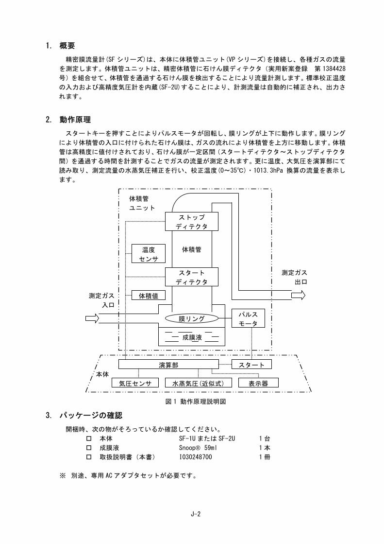
2. 動作原理 スタートキーを押すことによりパルスモータが回転し、膜リングが上下に動作します。膜リング
により体積管の入口に付けられた石けん膜は、ガスの流れにより体積管を上方に移動します。体積
管は高精度に値付けされており、石けん膜が一定区間(スタートディテクタ~ストップディテクタ
間)を通過する時間を計測することでガスの流量が測定されます。更に温度、大気圧を演算部にて
読み取り、測定流量の水蒸気圧補正を行い、校正温度(0~35℃)・1013.3hPa 換算の流量を表示し
ます。
図 1 動作原理説明図
3. パッケージの確認 開梱時、次の物がそろっているか確認してください。
本体 SF-1U または SF-2U 1 台
成膜液 Snoop® 59ml 1 本
取扱説明書(本書) I030248700 1 冊
※ 別途、専用 AC アダプタセットが必要です。
温度
センサ
体積値
パルス
モータ膜リング
体積管
体積管
ユニット
成膜液
測定ガス
入口
測定ガス
出口
演算部
気圧センサ 水蒸気圧(近似式)
スタート
表示器
本体
ストップ
ディテクタ
スタート
ディテクタ
J-3
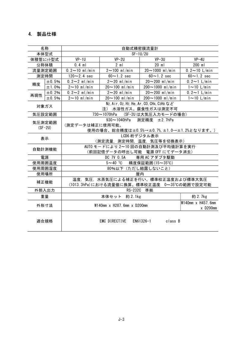
4. 製品仕様
名称 自動式精密膜流量計
本体型式 SF-1U/2U
体積管ユニット型式 VP-1U VP-2U VP-3U VP-4U
公称体積 0.4 ml 2 ml 20 ml 200 ml
流量測定範囲 0.2~10 ml/min 2~100 ml/min 20~1000 ml/min 0.2~10 L/min
測定時間 120~2.4 sec 60~1.2 sec 60~1.2 sec 60~1.2 sec
精度 ±0.5% 0.2~2 ml/min 2~20 ml/min 20~200 ml/min 0.2~1 L/min
±1.0% 2~10 ml/min 20~100 ml/min 200~1000 ml/min 1~10 L/min
再現性 ±0.2% 0.2~2 ml/min 2~20 ml/min 20~200 ml/min 0.2~1 L/min
±0.5% 2~10 ml/min 20~100 ml/min 200~1000 ml/min 1~10 L/min
対象ガス N2,Air,O2,H2,He,Ar,CO,CH4,C3H8など
注) 水溶性ガス、腐食性ガスは測定不可
気圧設定範囲 730~1070hPa (SF-2U は大気圧入力モードの場合)
気圧測定範囲
(SF-2U)
930~1040hPa 測定精度 ±2.7hPa
(測定データは補正に使用可能。
使用の場合、総合精度は±0.5%→±0.7%,±1.0→±1.2%となります。)
表示 LCD6 桁デジタル表示
(測定流量,測定時間,温度,気圧等を切換表示)
自動計測機能 AUTO モ-ドにより 2~10 回の自動計測及び平均値計算を実行
(前回記憶デ-タの呼出し可能 電源 OFF にてデータ消去)
電源 DC 7V 0.5A 専用 AC アダプタ駆動
使用周囲温度 5~40 ℃ 精度保証範囲(15~35℃)
使用周囲湿度 80%以下(ただし結露しないこと)
使用場所 屋内
補正機能 温度,気圧,水蒸気圧による補正を行い、標準校正温度および標準大気圧
(1013.3hPa)における流量値に換算。標準校正温度 0~35℃の範囲で設定可能
外部入出力 RS-232C 準拠
重量 本体セット 約 2.1kg 約 2.7kg
外形寸法 W140mm x H287.6mm x D200mm W140mm x H457.6mm
x D200mm
適合規格 EMC DIRECTIVE EN61326-1 class B

J-4
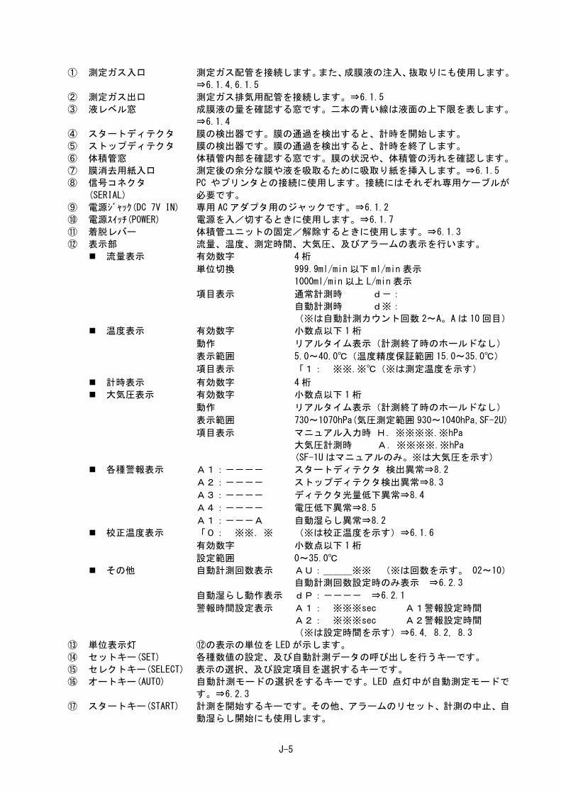
5. 各部説明
図 2 各部説明図
①
②③
④
⑤ ⑥
⑦
⑫
⑭
⑮ ⑯
⑰
⑧⑨
⑩
⑪
⑬
J-5
① 測定ガス入口 測定ガス配管を接続します。また、成膜液の注入、抜取りにも使用します。
⇒6.1.4,6.1.5
② 測定ガス出口 測定ガス排気用配管を接続します。⇒6.1.5
③ 液レベル窓 成膜液の量を確認する窓です。二本の青い線は液面の上下限を表します。
⇒6.1.4
④ スタートディテクタ 膜の検出器です。膜の通過を検出すると、計時を開始します。
⑤ ストップディテクタ 膜の検出器です。膜の通過を検出すると、計時を終了します。
⑥ 体積管窓 体積管内部を確認する窓です。膜の状況や、体積管の汚れを確認します。
⑦ 膜消去用紙入口 測定後の余分な膜や液を吸取るために吸取り紙を挿入します。⇒6.1.5
⑧ 信号コネクタ
(SERIAL)
PC やプリンタとの接続に使用します。接続にはそれぞれ専用ケーブルが
必要です。
⑨ 電源ジャック(DC 7V IN) 専用 AC アダプタ用のジャックです。⇒6.1.2
⑩ 電源スイッチ(POWER) 電源を入/切するときに使用します。⇒6.1.7
⑪ 着脱レバー 体積管ユニットの固定/解除するときに使用します。⇒6.1.3
⑫ 表示部 流量、温度、測定時間、大気圧、及びアラームの表示を行います。
流量表示 有効数字 4 桁
単位切換 999.9ml/min 以下 ml/min 表示
1000ml/min 以上 L/min 表示
項目表示 通常計測時 d-:
自動計測時 d※:
(※は自動計測カウント回数 2~A。A は 10 回目)
温度表示 有効数字 小数点以下 1桁
動作 リアルタイム表示(計測終了時のホールドなし)
表示範囲 5.0~40.0℃(温度精度保証範囲 15.0~35.0℃)
項目表示 「1: ※※.※℃(※は測定温度を示す)
計時表示 有効数字 4 桁
大気圧表示 有効数字 小数点以下 1桁
動作 リアルタイム表示(計測終了時のホールドなし)
表示範囲 730~1070hPa(気圧測定範囲 930~1040hPa,SF-2U)
項目表示 マニュアル入力時 H.※※※※.※hPa
大気圧計測時 A.※※※※.※hPa
(SF-1U はマニュアルのみ。※は大気圧を示す)
各種警報表示 A1:---- スタートディテクタ 検出異常⇒8.2
A2:---- ストップディテクタ検出異常⇒8.3
A3:---- ディテクタ光量低下異常⇒8.4
A4:---- 電圧低下異常⇒8.5
A1:---A 自動湿らし異常⇒8.2
校正温度表示 「0: ※※.※ (※は校正温度を示す)⇒6.1.6
有効数字 小数点以下 1桁
設定範囲 0~35.0℃
その他 自動計測回数表示 AU:___※※ (※は回数を示す。 02~10)
自動計測回数設定時のみ表示 ⇒6.2.3
自動湿らし動作表示 dP:---- ⇒6.2.1
警報時間設定表示 A1: ※※※sec A1警報設定時間
A2: ※※※sec A2警報設定時間
(※は設定時間を示す)⇒6.4, 8.2, 8.3
⑬ 単位表示灯 ⑫の表示の単位を LED が示します。
⑭ セットキー(SET) 各種数値の設定、及び自動計測データの呼び出しを行うキーです。
⑮ セレクトキー(SELECT) 表示の選択、及び設定項目を選択するキーです。
⑯ オートキー(AUTO) 自動計測モードの選択をするキーです。LED 点灯中が自動測定モードで
す。⇒6.2.3
⑰ スタートキー(START) 計測を開始するキーです。その他、アラームのリセット、計測の中止、自
動湿らし開始にも使用します。

J-6
6. 操作説明 6.1. 準備 6.1.1. 測定場所
重 要 次のような場所は測定場所として適しませんのでご注意ください。
床が傾斜している場所
直射日光や強い光の当たる場所
急激な温度変化を受ける場所
冷暖房機器に近い場所
振動のある場所
強力な強制吸排気を行っている場所
結露や濡れる可能性のある場所
強い風が当たる場所
扉の開閉の多い部屋
参 考 精密な測定を行う場合、温度管理された室内で恒温槽を用いて行ってください。
6.1.2. 電源接続 本体背面の電源ジャックに専用 AC アダプタ及び電源ケーブルを接続し、プラグをコンセントに
差し込んでください。
警告
専用ACアダプタを使用する。 それ以外を使用すると、火災や感電の原因になります。

J-7
6.1.3. 体積管ユニット装着 ① 測定流量にあった体積管ユニット(VP-1U~4U)をコネクタ及び接続部の切り欠きが本体接続
部のピンに合うように装着します。
② 着脱レバーを図の矢印の方向に回し固定します。
※ 体積管ユニットを取り外すときは②のレバーを戻し、SF 本体を押さえてゆっくりと取り外し
てください。
注意
体積管ユニットを確実に固定する。 体積管ユニットを本体に装着するときは着脱レバーの操作を確実に行い、固
定してください。固定せずに使用や持ち運びをしますと、転倒や脱落を招き、
けがや故障の原因となります。
図 3 体積管ユニット装着 図 4 成膜液注入
6.1.4. 成膜液注入 測定ガス入口に成膜液ボトルのチューブを 2~3cm 挿入し、泡が立たないようにゆっくりと注入し
ます。液レベル窓の二本の青い線の間に液面が来るように注入してください。
重 要 測定ガス入口に成膜液ボトルのチューブを 4cm 以上挿入しないでください。故障の原因になります。
成膜液は必ず Snoop®を使用してください。この他の石けん液や漏れ検査液を使用された場合、膜が出来なくなるだけではなく、体積管を汚れたり、内部のパッ
キンが劣化する場合があります。
液面は必ず二本の青い線の間に来るようにしてください。液の過不足は測定精度に悪影響を与えます。
①
② 切り欠き
ピン
成膜液
Snoop®
コネクタ
J-8
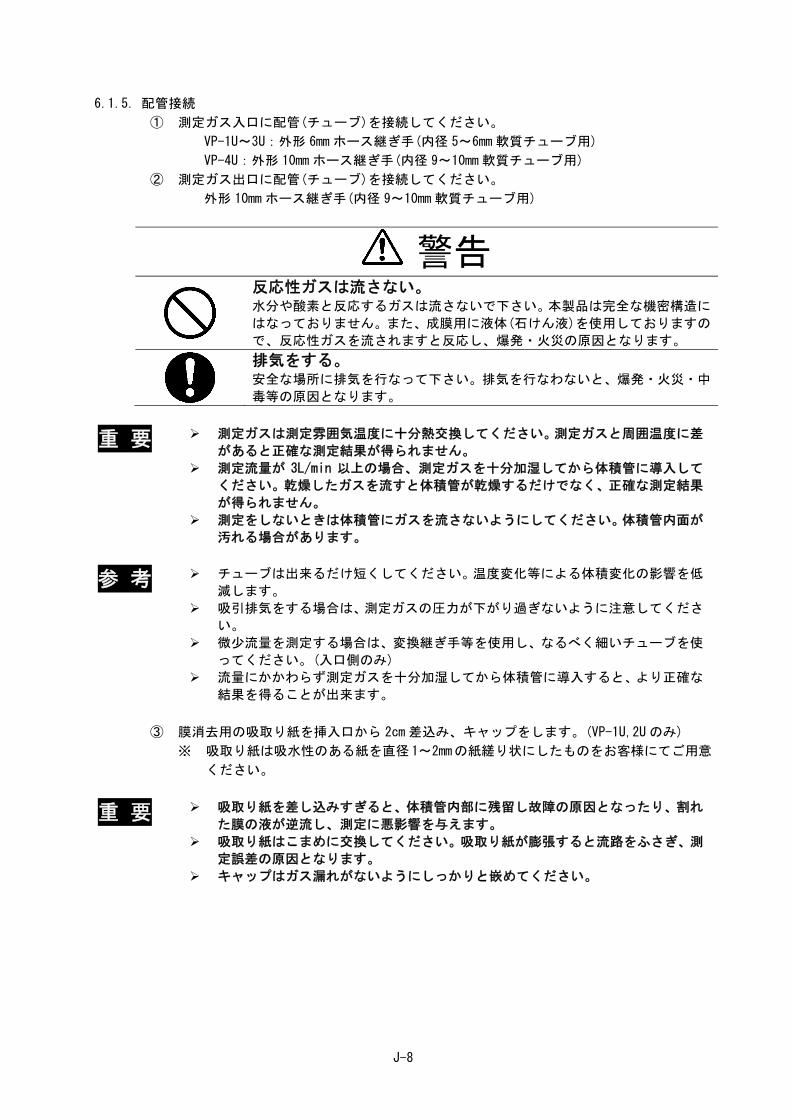
6.1.5. 配管接続 ① 測定ガス入口に配管(チューブ)を接続してください。
VP-1U~3U:外形 6mm ホース継ぎ手(内径 5~6mm 軟質チューブ用)
VP-4U:外形 10mm ホース継ぎ手(内径 9~10mm 軟質チューブ用)
② 測定ガス出口に配管(チューブ)を接続してください。
外形 10mm ホース継ぎ手(内径 9~10mm 軟質チューブ用)
警告
反応性ガスは流さない。 水分や酸素と反応するガスは流さないで下さい。本製品は完全な機密構造に
はなっておりません。また、成膜用に液体(石けん液)を使用しておりますの
で、反応性ガスを流されますと反応し、爆発・火災の原因となります。
排気をする。 安全な場所に排気を行なって下さい。排気を行なわないと、爆発・火災・中
毒等の原因となります。
重 要 測定ガスは測定雰囲気温度に十分熱交換してください。測定ガスと周囲温度に差があると正確な測定結果が得られません。
測定流量が 3L/min 以上の場合、測定ガスを十分加湿してから体積管に導入してください。乾燥したガスを流すと体積管が乾燥するだけでなく、正確な測定結果
が得られません。
測定をしないときは体積管にガスを流さないようにしてください。体積管内面が汚れる場合があります。
参 考 チューブは出来るだけ短くしてください。温度変化等による体積変化の影響を低減します。
吸引排気をする場合は、測定ガスの圧力が下がり過ぎないように注意してください。
微少流量を測定する場合は、変換継ぎ手等を使用し、なるべく細いチューブを使ってください。(入口側のみ)
流量にかかわらず測定ガスを十分加湿してから体積管に導入すると、より正確な結果を得ることが出来ます。
③ 膜消去用の吸取り紙を挿入口から 2cm 差込み、キャップをします。(VP-1U,2U のみ)
※ 吸取り紙は吸水性のある紙を直径1~2mmの紙縒り状にしたものをお客様にてご用意
ください。
重 要 吸取り紙を差し込みすぎると、体積管内部に残留し故障の原因となったり、割れた膜の液が逆流し、測定に悪影響を与えます。
吸取り紙はこまめに交換してください。吸取り紙が膨張すると流路をふさぎ、測定誤差の原因となります。
キャップはガス漏れがないようにしっかりと嵌めてください。
J-9
6.1.6. 校正温度設定 測定結果を表示する際の校正温度を設定します。(工場出荷時 25℃)
① セットキー”△”を押しながら、電源スイッチを入れ、そのままセットキー”△”を 5秒間押し続けてください。校正温度設定モードになります。
② セットキーを使い、希望の校正温度を設定してください。入力範囲は 0~35℃です。“△”と”▽”を同時に押すと 25℃になります。
③ 電源スイッチを切ると設定がエントリーされます。(電源を切っても設定値は記憶され
ています。)
※ 校正温度は次の二つの方法で確認できます。
通電開始直後、バージョン情報の後に表示されます。(約 3秒間)
温度表示の状態でセットキー“△” ”▽”のどちらかを押す。(自動測定モードを除く。)
6.1.7. 電源投入 電源スイッチを入れると、表示部にバージョン情報が表示され、引き続き校正温度が表示されま
す。(各々約 3秒間表示)
重 要 校正温度の設定が正しいことを確認してください。設定値が誤っていますと、正確な測定結果が得られません。
10 分以上暖機をしてください。センサ類が安定していないと、正確な測定結果が得られません。
6.2. 測定 6.2.1. 体積管湿らし
測定を開始する直前に体積管の内壁を湿らせておく必要があります。測定ガスまたは N2等の不活
性ガスを測定ガス入口に導入し、次の手順で体積管の内壁を湿らせてください。湿らし操作には次
の二つがあります。
参 考 ガスの流量を測定可能レンジの 5~20%にすると、湿らしがスムーズに行えます。
手動操作
① スタートキーを 1秒以上の間隔で繰り返し押してください。 ② ①の操作をしながら、体積管窓から膜の通過状況を観察してください。 ③ 膜がストップディテクタまで到達するようになったら①の操作を止め、体積管内の全ての膜
がストップディテクタを通過するまでお待ちください。
自動操作
① スタートキーを 1秒以上押し続けてください。
② 表示がdP:----となり、一定間隔で自動的に膜を作ります。
③ 膜がストップディテクタまで到達するようになり、湿らしが完了すると待機状態に戻ります。
※ 測定中にこの操作を行った場合、湿らし完了後、再度測定を開始します。
※ この操作を中止する場合はスタートキーを押してください。
重 要 体積管内に膜が残っていないことを確認してから測定を開始してください。石けん膜の性質上、偶発的に膜が残っている場合があります。膜が残っていると、正
確な測定結果が得られないことがあります。

J-10
6.2.2. 大気圧入力 SF-1U の場合
① セレクトキーを押し表示を大気圧表示にしてください。
② セットキーにより、大気圧を設定してください。(設定範囲:730~1070hPa)
セットキーの”△”と”▽”を同時に押すと、1013.3hPa になります。
SF-2U の場合
内蔵の大気圧センサの出力を使用しない場合、次の手順で大気圧を入力してください。
① セレクトキーを押し表示を大気圧表示にしてください。
② セットキーの”△”と”▽”を同時に 2秒以上押し続けてください。 ③ 大気圧入力モードになり、表示の左端の文字が”A”から”H”に変わり、単位表示灯が点灯から
点滅に変わります。
④ セットキーにより、大気圧を設定してください。(設定範囲:730~1070hPa)
セットキーの”△”と”▽”を同時に押すと、1013.3hPa になります。 ※ 大気圧入力モードを終了する場合、セットキーの”△”と”▽”を同時に 2 秒以上押し続けるか、電源スイッチを切ってください。
重 要 大気圧の設定が正しいことを確認してください。設定値が誤っていますと、正確な測定結果が得られません。
6.2.3. 測定 測定には通常測定と自動測定の 2 つの方法があります。自動測定では任意の回数の測定を自動で
行い、各回の測定値と総平均を得ることが出来ます。
通常測定
① スタートキーを押します。
② 膜がスタートディテクタに到達するまで表示がフラッシングします。
0.000
③ 膜がスタートディテクタに到達すると、計時を開始し、経過時間を表示します。
0.123 経過時間をカウント
④ 膜がストップディテクタに到達すると、計時を終了し、計測時間を表示した後、流量の表
示をします。
1.234 計測時間表示 ⇒ d-:10.23 流量表示
⑤ セレクトキーを押すと、表示が切り換わり、計測時間と流量が確認できます。
流量 ⇒ 温度 ⇒ 計測時間 ⇒ 大気圧 ⇒ 流量 ⇒・・・・
※ 測定値は次の測定、または電源を切るまでホールドされます。
※ 温度、及び大気圧の値についてはリアルタイム表示です。

J-11
自動測定
① オートキーを押してください。
② オートキーの表示灯が点灯し、自動測定モードになります。
③ セットキーにより自動測定の回数を設定してください。
AU: ※※ ※は回数設定値(02~10)
④ スタートキーを押すと、自動測定を開始します。
⑤ 開始直後のウォームアップとして 1回測定を行います。測定結果は無効になります。
各回の測定中には”※-”を表示し※回目の測定であることを示します。(※が”A”のときは 10 回目を示します。)その他の表示の流れは通常測定の場合と同じです。
⑥ 自動測定が終了すると断続的にブザーが鳴ります。
⑦ セットキーを押すと、表示が切り換わり、各回の測定値が確認できます。(”d1”~”d9”は 1~9 回目。”dA”は 10 回目。) 表示の左が”d0”の値は平均値を表します。 セレクトキーを押すと表示が切り換わり、計測時間、温度、大気圧が確認できます。
※ 自動測定を中止するときはセレクトキーを押しながらスタートキーを押してください。
※ 自動測定の間隔は前回測定時間の 1/4 となります。(但し、最短 3秒、最長 10 秒)
※ 自動測定モードを解除する場合、オートキーを押してください。オートキーの表示灯が消
灯します。
※ 自動測定モードを解除した後、自動測定の結果を確認する場合は、オートキーを 2 回押し
て自動測定モード/データ呼び出し状態にしてください。(オートキー表示灯が点滅)
※ 測定値は次の測定、または電源を切るまでホールドされます。
6.3. 演算式 流量算出には次式を用い、大気圧、温度、水蒸気圧補正を行います。
ここに
Q:流量(L/min, at 校正温度・1013.3hPa) t:測定温度(℃) V:ディテクタ間体積(L) Pa:大気圧(hPa) S:計測時間(sec) Pw:t℃での飽和水蒸気圧(hPa) T:0℃における絶対温度(=273K) Po:標準状態大気圧(=1013.3hPa) to:校正温度(℃)
6.4. 警報時間設定(工場出荷時 A1:120 秒,A2:120 秒) 精度保証流量の範囲を下回る流量の測定(例えば VP-2U を使用し、VP-1U の範囲を測定)を行う
場合等のために、A1/A2 アラ-ムの待機時間を変更することが出来ます。設定の変更は次の手順で
行ってください。
① セットキー” ▽” を押しながら電源スイッチを入れ、そのままセットキー”▽”を 5秒間押し続けてください。警報時間設定モードになります。
② セットキーを押して警報時間を設定してください。(設定範囲:1~999 秒)
③ セレクトキーを押すと、A1/A2 の切り換えが出来ます。
※セットキーの”△”と”▽”を同時に押すと 120 秒になります。(VP-1U 装着時は 180 秒) ④ 電源スイッチを切ってください。
Po
PwPa
tT
toT
S
VQ
60

J-12
7. 保守 7.1. 日常保守 7.1.1. 成膜液の補充
液レベル窓より常に液量を確認してください。液レベルが下の青い線に近づきましたら、成膜液
を補充してください。⇒6.1.4
7.1.2. 成膜液の交換 液が汚れたり、膜ができにくくなった場合は速やかに成膜液を交換してください。
体積管ユニットを傾け、測定ガス入口より液を排出し、新しい成膜液を注入してください。⇒6.1.4
7.1.3. 体積管の洗浄 体積管が汚れた場合、次の手順で洗浄してください。
① 体積管ユニットを傾け、測定ガス入口より液を排出してください。
② 体積管ユニットより長めのビニールチューブ等を測定ガス入口に接続してください。
③ ビニールチューブの端を持ち上げた状態で、きれいな水(汚れがひどい場合は中性洗剤
等)を注入し、ストップディテクタの位置まで体積管内を満たしてください。
④ しばらく放置した後、ビニールチューブの端を下ろし、水(洗剤)を排出してください。
⑤ 洗剤を使用した場合はきれいな水で③④の操作を 2~3 回行ってください。
⑥ 液を完全に排出できたら、成膜液を注入してください。⇒6.1.4
7.2. 定期点検 いつまでも精度よくお使いいただくために、定期点検・精度確認・再校正を有償にて行います。
詳しくは、お買い求めいただいた代理店、または弊社までお問い合わせください。SF-2U,VP につき
ましては 1年毎の精度確認をお奨めします。
7.2.1. 定期交換部品 使用頻度、測定流体等により異なりますが、下記の期間を目安に部品交換(有償)をお奨めしま
す。定期交換部品の交換は、弊社にて実施いたします。お客様ご自身による交換はできません。
パルスモータアッセン 2 年毎
成膜機構アッセン 2 年毎
シールキット 2 年毎 又は 分解時
内部配管 3 年毎
その他部品 必要時
7.2.2. 保守部品
成膜液 Snoop® 236ml No.S000025(3024000025)
専用 AC アダプタセット PS-SF-100C(日本国内用) No.S242802(3200496396)
専用 AC アダプタ (ヨーロッパ用) 御入用時、弊社までご相談ください。
専用 AC コードセット (ヨーロッパ用) 御入用時、弊社までご相談ください。

J-13
8. トラブルチャート
万一、本装置が正常に動作しない場合は、敏速なサ-ビス対応を行う為、弊社に修理の依頼をさ
れる前に可能な限り、次の各項目により点検を行って下さい。
8.1. 電源が入らない
電源が入らない
供給電源確認 異常
正常 電源供給
異常 ACアダプタ
/コネクタ確認
再差込 正常
※配線・基板
点検・修理・交換
※印は幣社又は代理店作業になります。修理依頼を願います。

J-14
8.2. A1 アラーム発生 (スタートディテクタ検出異常)
A1 アラーム発生
成膜状態確認 異常
正常 成膜動作確認 異常
異常
測定流量確認
正常
VP交換 正常 ※修理
異常 成膜液量
警報時間確認 確認 異常
時間設定 正常 正常 液量調節
成膜液 異常
の汚れ
正常
交換
異常 体積管内
の汚れ
洗浄 正常
※ディテクタ
点検、修理、オーバーホール
※印は幣社又は代理店作業になります。修理依頼を願います。
A1 アラーム (表示 A1:----)
成膜~スタートディテクタ検出時間が、膜割れ/測定範囲外流量等により 120 秒(VP-1U
は 180 秒)経過した場合発生します。体積管の湿らし操作・測定流量確認等を行って下さ
い。尚、警報時間(120/180 秒)は変更可能です。⇒6.4
自動湿らしアラーム発生 (表示 A1:---A)
自動湿らし動作を 120 秒間実行しても、体積管内壁が湿らない場合に発生します。測定
流量、成膜液量等を確認して下さい。尚、警報時間 120 秒は変更可能です。⇒6.4(A1 ア
ラーム時間と共通)
体積管の洗浄方法⇒7.1.3
アラーム解除は、スタートキーを押して下さい。

J-15
8.3. A2 アラーム発生 (ストップディテクタ検出異常)
A2 アラーム発生
成膜状態確認 異常
正常 成膜動作確認 異常
異常
測定流量確認
VP交換 正常 正常 ※修理
異常
警報時間確認 成膜液 異常
の汚れ
時間設定 正常
正常 交換
異常 体積管内
の汚れ
正常
洗浄
※ディテクタ
点検、修理、オーバーホール
※印は幣社又は代理店作業になります。修理依頼を願います。
A2 アラーム (表示 A2:----)
ストップディテクタ検出異常です。スタートディテクタ~ストップディテクタ検出時間
が、膜割れ/測定範囲外流量等により 120 秒(VP-1U は 180 秒)経過した場合発生します。
体積管の湿らし操作・測定流量確認等を行って下さい。尚、警報時間(120 秒/180 秒)
は変更可能です。⇒6.4
体積管の洗浄方法⇒7.1.3
アラーム解除は、スタートキーを押して下さい。
J-16
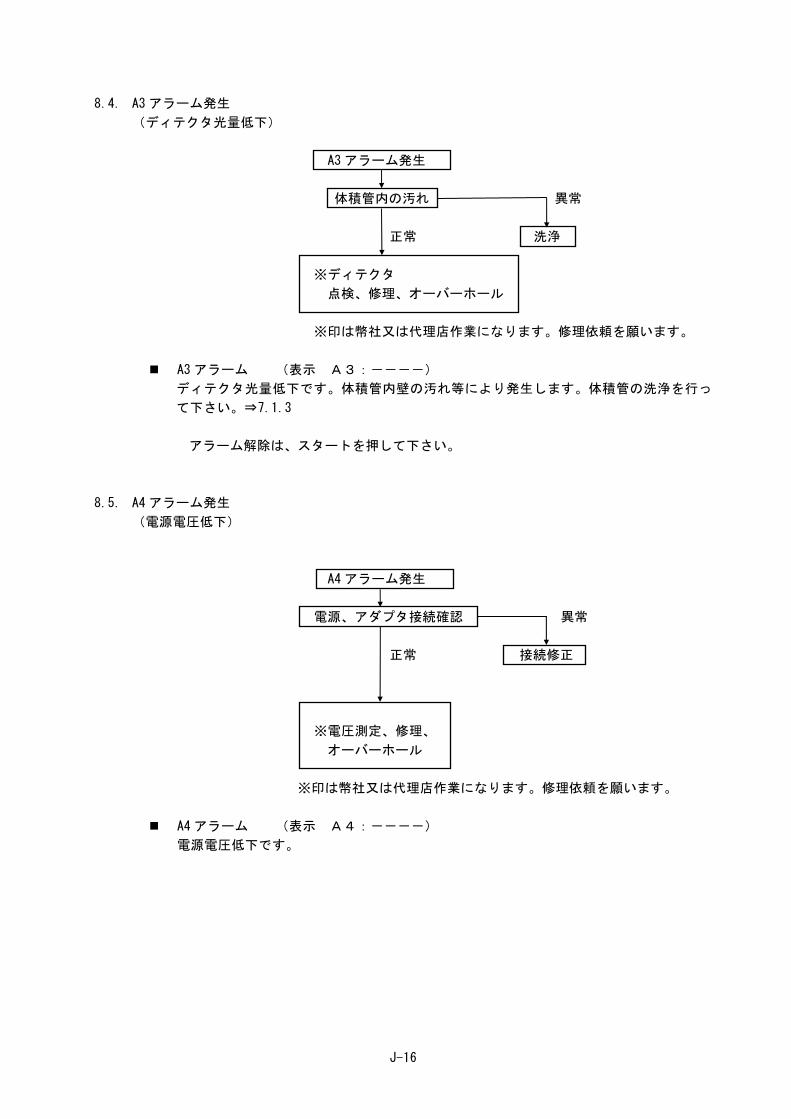
8.4. A3 アラーム発生 (ディテクタ光量低下)
A3 アラーム発生
体積管内の汚れ 異常
正常 洗浄
※ディテクタ
点検、修理、オーバーホール
※印は幣社又は代理店作業になります。修理依頼を願います。
A3 アラーム (表示 A3:----)
ディテクタ光量低下です。体積管内壁の汚れ等により発生します。体積管の洗浄を行っ
て下さい。⇒7.1.3
アラーム解除は、スタートを押して下さい。
8.5. A4 アラーム発生 (電源電圧低下)
A4 アラーム発生
電源、アダプタ接続確認 異常
正常 接続修正
※電圧測定、修理、
オーバーホール
※印は幣社又は代理店作業になります。修理依頼を願います。
A4 アラーム (表示 A4:----)
電源電圧低下です。

J-17
8.6. 膜が複数枚出来る
膜が複数枚出来る
異常 成膜液量確認
液量調節 正常
※膜割機構、成膜機構、成膜リング、体積管
確認、調節、オーバーホール、交換
※印は幣社又は代理店作業になります。修理依頼を願います。
8.7. 時計をカウントしない
時計カウント異常
異常 成膜液の汚れ
交換 正常
体積管の汚れ 異常
正常 洗浄
※ディテクタ
点検、修理、オーバーホール
※印は幣社又は代理店作業になります。修理依頼を願います。
体積管の洗浄方法⇒7.1.3
J-I
付録 A コンピュータ通信仕様
SF-1U/U2 を通信用の専用ケーブルでホストコンピュータ(CPU)に接続することにより、流量計
測をプログラムによって自動的に行う事が出来ます。
1. 接続方法 1.1. ハード仕様(RS-232C 規格準拠)
① 歩調同期(非同期)方式 ② データビット 8 ビット/1 キャラクタ ③ ストップビット 2 ビット ④ パリティ NON
1.2. ボーレート設定(工場出荷時 9600 bps) ボーレート設定を以下の手順で行って下さい。
① オートキーを押しながら、電源スイッチを入れ、そのままオートキーを 5秒間押し続けてください。ボーレート設定状態になります。
② 表 示 部 を見 な が らセ ッ ト キー に よ り選 択 を 行っ て 下 さい 。 ボ ーレ ー ト は9600/4800/2400/1200bps から選択可能です。
③ 電源スイッチを切り、ボーレート設定状態を解除して下さい。
1.3. 通信状態での起動 通信用の専用ケーブルをホストコンピュ-タ(CPU)に接続した後、本体の電源を入れて下さい。
ホストコンピュ-タ(CPU)による本体の遠隔制御が可能になります。
1.4. 専用ケーブル 通信ケーブルは次の弊社製ケーブルを使用してください。※
名称:SF ケーブル 型式:SC-NSF-PCV (2m) No. S089362(3024059056)
※市販の RS-232C クロスケーブル(標準規格)とは仕様が異なります。
J-II
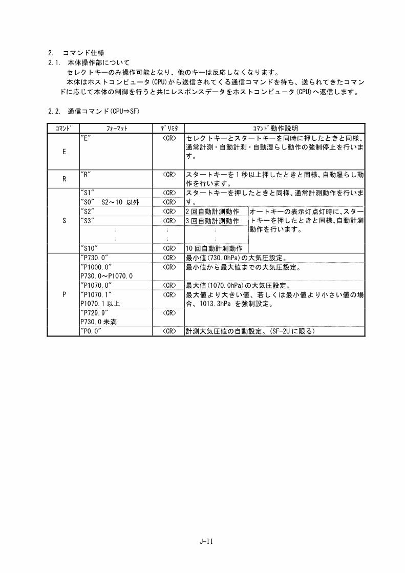
2. コマンド仕様 2.1. 本体操作部について
セレクトキーのみ操作可能となり、他のキーは反応しなくなります。
本体はホストコンピュータ(CPU)から送信されてくる通信コマンドを待ち、送られてきたコマン
ドに応じて本体の制御を行うと共にレスポンスデータをホストコンピュ-タ(CPU)へ返信します。
2.2. 通信コマンド(CPU⇒SF)
コマンド フォ-マット デリミタ コマンド動作説明
E
"E" <CR> セレクトキーとスタートキーを同時に押したときと同様、
通常計測・自動計測・自動湿らし動作の強制停止を行いま
す。
R "R" <CR> スタートキーを 1秒以上押したときと同様、自動湿らし動
作を行います。
S
"S1" <CR> スタートキーを押したときと同様、通常計測動作を行いま
す。 "S0" S2~10 以外 <CR>
"S2" <CR> 2 回自動計測動作 オートキーの表示灯点灯時に、スター
トキーを押したときと同様、自動計測
動作を行います。 "S3" <CR> 3 回自動計測動作
⋮
⋮
⋮
⋮
⋮
⋮
"S10" <CR> 10 回自動計測動作
P
"P730.0" <CR> 最小値(730.0hPa)の大気圧設定。
"P1000.0"
P730.0~P1070.0
<CR> 最小値から最大値までの大気圧設定。
"P1070.0" <CR> 最大値(1070.0hPa)の大気圧設定。
"P1070.1"
P1070.1 以上
<CR> 最大値より大きい値、若しくは最小値より小さい値の場
合、1013.3hPa を強制設定。
"P729.9"
P730.0 未満
<CR>
"P0.0" <CR> 計測大気圧値の自動設定。(SF-2U に限る)

J-III
2.3. 通信コマンド(SF⇒CPU) ※コンピュータは、常に受信可能状態にしておいて下さい。
① S コマンドによる通常計測動作及び自動計測動作が正常に終了した場合、以下の順序にて計測結果を返信します。
順序 フォ-マット デリミタ レスポンスデ-タ説明
1
"FRML123.4" <CR> 通常計測 1L/min 未満のときの測定流量
各流量範囲での少数点の位置
0.000~9.999ml/min
10.00~99.99ml/min
100.0~999.9ml/min
※ 自動計測の ”:”はデータの区切りです。最初のデータは、平
均値であり、その後順番に 1~
10 回目のデータとなります。
"FRML123.4:123.4:123.4" <CR> 2 回自動計測
"FRML123.4:123.4:123.4:123.4" <CR> 3 回自動計測
⋮
⋮
⋮
⋮
⋮
⋮
"FRML123.4:123.4:123.4:123.4
:123.4:123.4:123.4:123.4
:123.4:123.4:123.4"
<CR> 10 回自動計測
"FRL1.234" <CR> 通常計測 1L/min 以上のときの測定流量
各流量範囲での少数点の位置
1.000~9.999L/min
10.00~ L/min
※ 自動計測の ”:”はデータの区切りです。最初のデータは、平
均値であり、その後順番に 1~
10 回目のデータとなります。
"FRL1.234:1.234:1.234" <CR> 2 回自動計測
"FRL1.234:1.234:1.234:1.234" <CR> 3 回自動計測
⋮
⋮
⋮
⋮
⋮
⋮
"FRL123.4:123.4:123.4:123.4
:123.4:123.4:123.4:123.4
:123.4:123.4:123.4"
<CR> 10 回自動計測
2
"TIME12.54" <CR> 通常計測 測定時間各時間範囲での少数点の
位置
0.000~9.999sec
10.00~99.99 sec
100.0~999.9sec
※ 自動計測の ”:”はデータの区切りです。最初のデータは、平
均値であり、その後順番に 1~
10 回目のデ-タとなります。
"TIME12.54:12.54:12.54" <CR> 2 回自動計測
"TIME12.54:12.54:12.54:12.54" <CR> 3 回自動計測
⋮
⋮
⋮
⋮
⋮
⋮
"TIME12.54:12.54:12.54:12.54
:12.54:12.54:12.54:12.54
:12.54:12.54:12.54"
<CR> 10 回自動計測
3 "ST.T_25.0" <CR> 基準校正温度 ※_は空白です。
"ST.T__0.0" <CR>
4 "MJ.T_25.4" <CR> 計測温度 ※_は空白です。
"MJ.T__9.4" <CR>
5 "AT.P1070.0" <CR> 設定大気圧 ※_は空白です。
"AT.P_730.0" <CR>
1,2,3,4,5 のデータフォーマットについて・・・
1 自動計測回数及び計測流量範囲により、1の中から何れかを選択して、データを返信します。
2 自動計測回数及び計測時間範囲により、2の中から何れかを選択して、データを返信します。
3 基準校正温度が 10.0℃以上か 10.0℃未満により、3 の中から何れかを選択して、データを返信します。
4 計測温度が 10.0℃以上か 10.0℃未満により、4 の中から何れかを選択して、データを返信します。
5 設定大気圧が1000.0hPa以上か1000.0hPa未満により、5の中から何れかを選択して、データを返信します。
J-IV
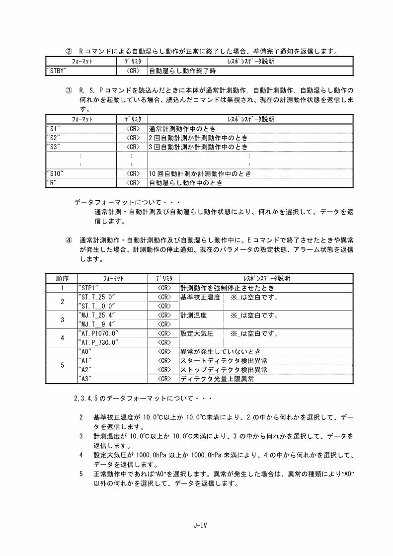
② R コマンドによる自動湿らし動作が正常に終了した場合、準備完了通知を返信します。 フォ-マット デリミタ レスポンスデ-タ説明
"STBY" <CR> 自動湿らし動作終了時
③ R,S,P コマンドを読込んだときに本体が通常計測動作,自動計測動作,自動湿らし動作の何れかを起動している場合、読込んだコマンドは無視され、現在の計測動作状態を返信しま
す。
フォ-マット デリミタ レスポンスデ-タ説明
"S1" <CR> 通常計測動作中のとき
"S2" <CR> 2 回自動計測か計測動作中のとき
"S3" <CR> 3 回自動計測か計測動作中のとき
⋮
⋮
⋮
⋮
⋮
⋮
"S10" <CR> 10 回自動計測か計測動作中のとき
"R" <CR> 自動湿らし動作中のとき
デ-タフォ-マットについて・・・
通常計測・自動計測及び自動湿らし動作状態により、何れかを選択して、データを返
信します。
④ 通常計測動作・自動計測動作及び自動湿らし動作中に、Eコマンドで終了させたときや異常が発生した場合、計測動作の停止通知、現在のパラメータの設定状態、アラーム状態を返信
します。
順序 フォ-マット デリミタ レスポンスデ-タ説明
1 "STP1" <CR> 計測動作を強制停止させたとき
2 "ST.T_25.0" <CR> 基準校正温度 ※_は空白です。
"ST.T__0.0" <CR>
3 "MJ.T_25.4" <CR> 計測温度 ※_は空白です。
"MJ.T__9.4" <CR>
4 "AT.P1070.0" <CR> 設定大気圧 ※_は空白です。
"AT.P_730.0" <CR>
5
"A0" <CR> 異常が発生していないとき
"A1" <CR> スタートディテクタ検出異常
"A2" <CR> ストップディテクタ検出異常
"A3" <CR> ディテクタ光量上限異常
2,3,4,5 のデータフォーマットについて・・・
2 基準校正温度が 10.0℃以上か 10.0℃未満により、2 の中から何れかを選択して、データを返信します。
3 計測温度が 10.0℃以上か 10.0℃未満により、3 の中から何れかを選択して、データを返信します。
4 設定大気圧が 1000.0hPa 以上か 1000.0hPa 未満により、4 の中から何れかを選択して、データを返信します。
5 正常動作中であれば”A0”を選択します。異常が発生した場合は、異常の種類により”A0”以外の何れかを選択して、データを返信します。
J-V
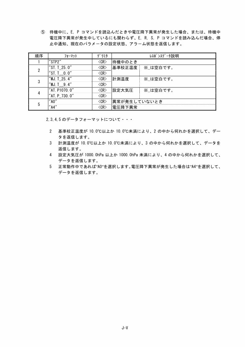
⑤ 待機中に、E,P コマンドを読込んだときや電圧降下異常が発生した場合、または、待機中電圧降下異常が発生中しているにも関わらず、E,R,S,P コマンドを読み込んだ場合、停
止中通知、現在のパラメ-タの設定状態、アラ-ム状態を返信します。
順序 フォ-マット デリミタ レスポンスデ-タ説明
1 "STP2" <CR> 待機中のとき
2 "ST.T_25.0" <CR> 基準校正温度 ※_は空白です。
"ST.T__0.0" <CR>
3 "MJ.T_25.4" <CR> 計測温度 ※_は空白です。
"MJ.T__9.4" <CR>
4 "AT.P1070.0" <CR> 設定大気圧 ※_は空白です。
"AT.P_730.0" <CR>
5 "A0" <CR> 異常が発生していないとき
"A4" <CR> 電圧降下異常
2,3,4,5 のデータフォーマットについて・・・
2 基準校正温度が 10.0℃以上か 10.0℃未満により、2 の中から何れかを選択して、データを返信します。
3 計測温度が 10.0℃以上か 10.0℃未満により、3 の中から何れかを選択して、データを返信します。
4 設定大気圧が 1000.0hPa 以上か 1000.0hPa 未満により、4 の中から何れかを選択して、データを返信します。
5 正常動作中であれば”A0”を選択します。電圧降下異常が発生した場合は”A4”を選択して、データを返信します。
J-VI
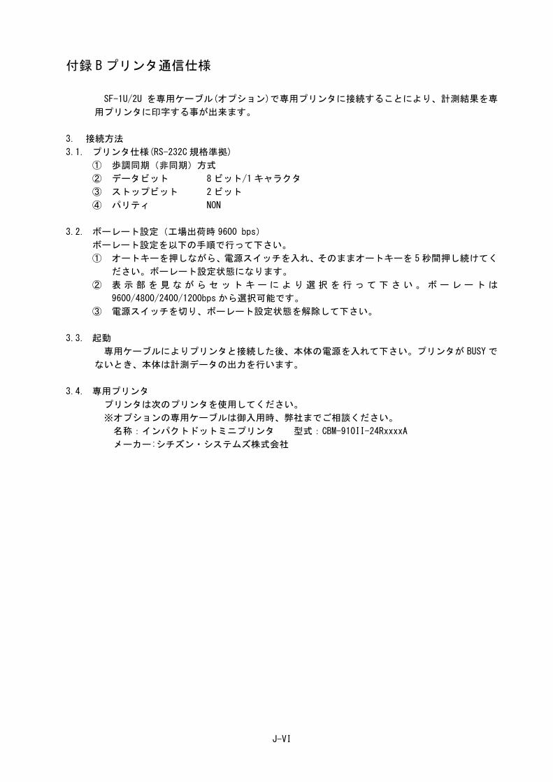
付録 B プリンタ通信仕様
SF-1U/2U を専用ケーブル(オプション)で専用プリンタに接続することにより、計測結果を専
用プリンタに印字する事が出来ます。
3. 接続方法 3.1. プリンタ仕様(RS-232C 規格準拠)
① 歩調同期(非同期)方式 ② データビット 8 ビット/1 キャラクタ ③ ストップビット 2 ビット ④ パリティ NON
3.2. ボーレート設定(工場出荷時 9600 bps) ボーレート設定を以下の手順で行って下さい。
① オートキーを押しながら、電源スイッチを入れ、そのままオートキーを 5秒間押し続けてください。ボーレート設定状態になります。
② 表 示 部 を見 な が らセ ッ ト キー に よ り選 択 を 行っ て 下 さい 。 ボ ーレ ー ト は9600/4800/2400/1200bps から選択可能です。
③ 電源スイッチを切り、ボーレート設定状態を解除して下さい。
3.3. 起動 専用ケーブルによりプリンタと接続した後、本体の電源を入れて下さい。プリンタが BUSY で
ないとき、本体は計測データの出力を行います。
3.4. 専用プリンタ プリンタは次のプリンタを使用してください。
※オプションの専用ケーブルは御入用時、弊社までご相談ください。
名称:インパクトドットミニプリンタ 型式:CBM-910II-24RxxxxA
メーカー:シチズン・システムズ株式会社

J-VII
4. プリントアウト仕様
計測が正常に終了したときに、以下の計測デ-タの出力を行います。
通常計測データプリンタフォーマット
例 1 例 2 **** STD.TEMP 25.0 ゚ C** **** STD.TEMP 0.0 ゚ C** **** Ordinal**** Ordinal FLOW RATE 1.984 l/min FLOW RATE 1.984 ml/min TEMPERATURE 24.8 ゚ C TEMPERATURE 9.9 ゚ C AT.PRESSURE 1013.0hPa AT.PRESSURE 1013.0hPa TIME 1.009 sec TIME 1.009 sec
自動計測データプリンタフォーマット 例 1 例 2 **** STD.TEMP 25.0 ゚ C** **** STD.TEMP 0.0 ゚ C** **** First time **** First time FLOW RATE 1.984 l/min FLOW RATE 1.984 ml/min TEMPERATURE 24.8 ゚ C TEMPERATURE 9.9 ゚ C AT.PRESSURE 1013.0hPa AT.PRESSURE 1013.0hPa TIME 1.009 sec TIME 1.009 sec **** Second time **** Second time FLOW RATE 1.984 l/min FLOW RATE 1.984 ml/min TEMPERATURE 24.8 ゚ C TEMPERATURE 9.9 ゚ C AT.PRESSURE 1013.0hPa AT.PRESSURE 1013.0hPa TIME 1.009 sec TIME 1.009 sec **** Third time **** Third time FLOW RATE 1.984 l/min FLOW RATE 1.984 ml/min TEMPERATURE 24.8 ゚ C TEMPERATURE 9.9 ゚ C AT.PRESSURE 1013.0hPa AT.PRESSURE 1013.0hPa TIME 1.009 sec TIME 1.009 sec
⋮ ⋮
⋮ ⋮ **** Tenth time **** Tenth time FLOW RATE 1.984 l/min FLOW RATE 1.984 ml/min TEMPERATURE 24.8 ゚ C TEMPERATURE 9.9 ゚ C AT.PRESSURE 1013.0hPa AT.PRESSURE 1013.0hPa TIME 1.009 sec TIME 1.009 sec **** Average **** Average FLOW RATE 1.984 l/min FLOW RATE 1.984 ml/min TEMPERATURE 24.8 ゚ C TEMPERATURE 9.9 ゚ C AT.PRESSURE 1013.0hPa AT.PRESSURE 1013.0hPa TIME 1.009 sec TIME 1.009 sec
※ FLOW RATE の単位は、計測流量値によって自動的に変ります。
1 L/min 未満のときの単位: “ml/min” 1 L/min 以上のときの単位: “l/min”
※ 各数値は本体のLCD表示値と同じ値の出力を行います。
※ プリンタはオンラインになっている条件で出力を行います。
E-i
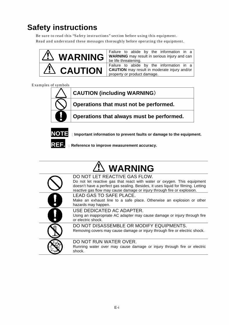
Safety instructions Be sure to read this “Safety instructions” section before using this equipment. Read and understand these messages thoroughly before operating the equipment.
WARNINGFailure to abide by the information in a WARNING may result in serious injury and can be life threatening.
CAUTION Failure to abide by the information in a CAUTION may result in moderate injury and/or property or product damage.
Examples of symbols
CAUTION (including WARNING)
Operations that must not be performed.
Operations that always must be performed.
NOTE :Important information to prevent faults or damage to the equipment.
REF. :Reference to improve measurement accuracy.
WARNING
DO NOT LET REACTIVE GAS FLOW. Do not let reactive gas that react with water or oxygen. This equipment doesn’t have a perfect gas sealing. Besides, it uses liquid for filming. Letting reactive gas flow may cause damage or injury through fire or explosion.
LEAD GAS TO SAFE PLACE. Make an exhaust line to a safe place. Otherwise an explosion or other hazards may happen.
USE DEDICATED AC ADAPTER. Using an inappropriate AC adapter may cause damage or injury through fire or electric shock.
DO NOT DISASSEMBLE OR MODIFY EQUIPMENTS. Removing covers may cause damage or injury through fire or electric shock.
DO NOT RUN WATER OVER. Running water over may cause damage or injury through fire or electric shock.

E-ii
CAUTION
DO NOT SHORT CIRCUIT CONNECTER TERMINALS. Short circuit may cause damage or injury through fire.
AVOID IMPACT This equipment has a glass tube inside. Having impact may cause damage or injury through glass broken.
BE SURE TO FIX MEASURING UNIT. Make sure that the measuring unit is fixed to the main body by turning the fixing lever when you install. Carrying or using them without fixing may cause damage or injury through dropping or turning over
UNPLUG WHEN NOT IN USE FOR A LONG TERM. Leaving plug when not in use may cause damage or injury through fire or electric shock.
WARNING LABEL AND ITS LOCATION

E-iii
Conformable Directive
This equipment conforms to the following directives and standards;
[the EMC Directive]
EN61326-1
Emission: class B
Immunity: Basic electromagnetic environment
This product is not intended for use in industrial environments. In an industrial environment,
electromagnetic environmental effects may cause the incorrect performance of the product in
which case the user may be required to take adequate measures.
● Information on Disposal of Electrical and Electronic Equipment
The crossed out wheeled bin symbol shown on the product or
accompanying documents indicates separate collection for waste electrical
and electronic equipment (WEEE) under the WEEE Directive 2002/96/EC
in the European Union.
This product should not be disposed of as unsorted household waste.
Your correct disposal of WEEE will contribute to reducing wasteful consumption of natural
resources and protecting human health and the environment from potential negative effects
caused by hazardous substances in products.
Contact your supplier for information on applicable disposal methods.
E-iv
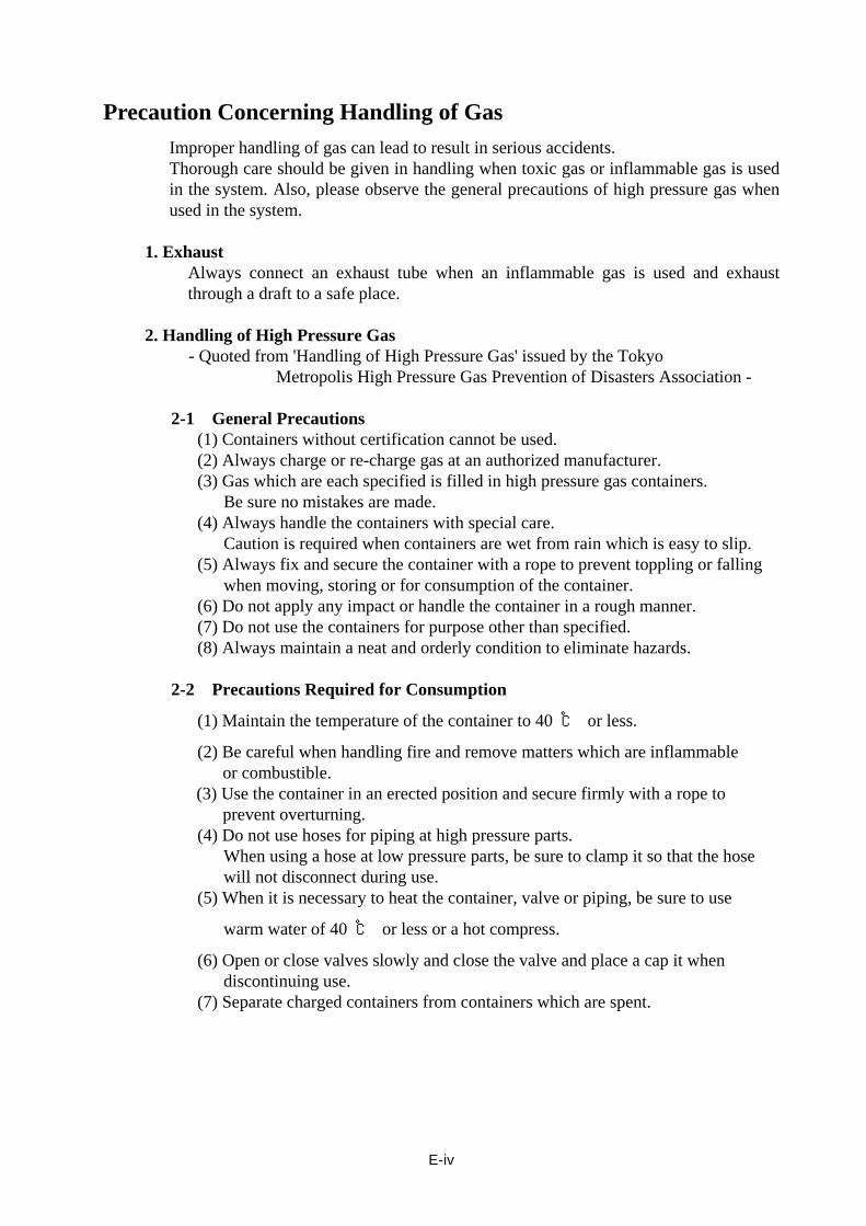
Precaution Concerning Handling of Gas Improper handling of gas can lead to result in serious accidents. Thorough care should be given in handling when toxic gas or inflammable gas is used in the system. Also, please observe the general precautions of high pressure gas when used in the system.
1. Exhaust
Always connect an exhaust tube when an inflammable gas is used and exhaust through a draft to a safe place.
2. Handling of High Pressure Gas - Quoted from 'Handling of High Pressure Gas' issued by the Tokyo Metropolis High Pressure Gas Prevention of Disasters Association - 2-1 General Precautions (1) Containers without certification cannot be used. (2) Always charge or re-charge gas at an authorized manufacturer. (3) Gas which are each specified is filled in high pressure gas containers. Be sure no mistakes are made. (4) Always handle the containers with special care. Caution is required when containers are wet from rain which is easy to slip. (5) Always fix and secure the container with a rope to prevent toppling or falling when moving, storing or for consumption of the container. (6) Do not apply any impact or handle the container in a rough manner. (7) Do not use the containers for purpose other than specified. (8) Always maintain a neat and orderly condition to eliminate hazards. 2-2 Precautions Required for Consumption
(1) Maintain the temperature of the container to 40 ℃ or less.
(2) Be careful when handling fire and remove matters which are inflammable or combustible. (3) Use the container in an erected position and secure firmly with a rope to prevent overturning.
(4) Do not use hoses for piping at high pressure parts. When using a hose at low pressure parts, be sure to clamp it so that the hose will not disconnect during use. (5) When it is necessary to heat the container, valve or piping, be sure to use
warm water of 40 ℃ or less or a hot compress.
(6) Open or close valves slowly and close the valve and place a cap it when discontinuing use. (7) Separate charged containers from containers which are spent.

Contents
page
Introduction ......................................................................................................................................... 1 1. Outline. .......................................................................................................................................... 2 2. Principles ...................................................................................................................................... 2 3. Checking the Accessories ........................................................................................................... 2 4. Specifications ............................................................................................................................... 3 5. Description of each part .............................................................................................................. 4 6. Operating Instructions ................................................................................................................. 6
6.1. Preparation ............................................................................................................................. 6 6.1.1. Measurement site ............................................................................................................ 6 6.1.2. Power connection ............................................................................................................ 6 6.1.3. Installing measuring unit .................................................................................................. 7 6.1.4. Pouring filming liquid ....................................................................................................... 7 6.1.5. Piping .............................................................................................................................. 8 6.1.6. Setting calibration temperature ........................................................................................ 9 6.1.7. Turning on the power switch ............................................................................................ 9
6.2. Measurement ........................................................................................................................ 10 6.2.1. Wetting inside measuring tube ...................................................................................... 10 6.2.2. Entering atmospheric pressure ...................................................................................... 10 6.2.3. Measurement ................................................................................................................ 11
6.3. Explanation on flow rate expression ..................................................................................... 12 6.4. Alarm time setting ................................................................................................................. 12
7. MAINTENANCE ........................................................................................................................... 13 7.1. Daily maintenance ................................................................................................................ 13
7.1.1. Replenishing filming liquid ............................................................................................. 13 7.1.2. Replacement of filming liquid ......................................................................................... 13 7.1.3. Cleaning measuring tube ............................................................................................... 13
7.2. Periodical maintenance ........................................................................................................ 13 7.2.1. Parts replacement frequencies ...................................................................................... 13 7.2.2. Maintenance parts list.................................................................................................... 13
8. Troubleshooting ......................................................................................................................... 14 8.1. The equipment is not turned on ............................................................................................ 14 8.2. A1 alarm ............................................................................................................................... 15 8.3. A2 alarm ............................................................................................................................... 16 8.4. A3 alarm ............................................................................................................................... 17 8.5. A4 alarm ............................................................................................................................... 17 8.6. More than one film are created ............................................................................................. 18 8.7. Clock does not work ............................................................................................................. 18
APPENDIX A Computer communication specifications .......................................................................... I APPENDIX B Printer communication specifications ............................................................................. VI

E-1
Introduction Your purchase of the FILM FLOW METER SF-1U/SF-2U is greatly appreciated. This instruction manual describes the operating procedures and simple maintenance procedures of the equipment. Before operating this product, please read the instructions carefully and save this manual for future use. Always operate and maintain the equipment correctly so that the HORIBA STEC,CO.,LTD. product can serve you best over a long period of time. If you have any questions or encounter product failure, contact HORIBA STEC,CO.,LTD. or the closest agent of ours.
Product Guarantee Term of guarantee
Equipment is guaranteed for one (1) year after the day of acceptance validation. If any failure occurs and we are informed of the failure during this period, we will repair equipment free of charge. If any initial failure occurs or if a failure or nonconformity occurs despite observation of instructions in the instruction manual, we will repair or replace defective parts free of charge. We will charge for repairing or replacing defective parts after the term of the guarantee and for upgrading hardware or software. The standard service life of this equipment is ten (10) years after manufacture for reasons of safety and reservation of parts.
Scope of guarantee This guarantee applies only to this equipment. The guarantee does not cover, for example, damage caused by failure of this equipment (loss of profit, customer confidence, facilities, and properties). The user shall be responsible for safety in the use of this equipment and its peripherals. For the recommended maintenance period and consumables, see details of maintenance and recommended periods in the instruction manual.
Exemptions
The user will be charged for repair or replacement of parts even within the term of the guarantee if a failure occurs for the following reasons:
Failure is caused by any inevitable accident, such as a natural disaster. Failure is caused by improper handling or negligence in attention. Equipment is used or stored under inappropriate environmental conditions. Equipment is used over the rated range or is modified or used for an unintended
purpose. We are not responsible for failure or the failure has been separately defined.
・ Unauthorized reprinting or copy of this manual is not strictly prohibited. ・ The contents of this manual are subject to change without notice. ・ This manual has been carefully written. However, if you find any oversights, please let us
know. ・ Snoop® is a registered trademark of Swagelok Company.
E-2
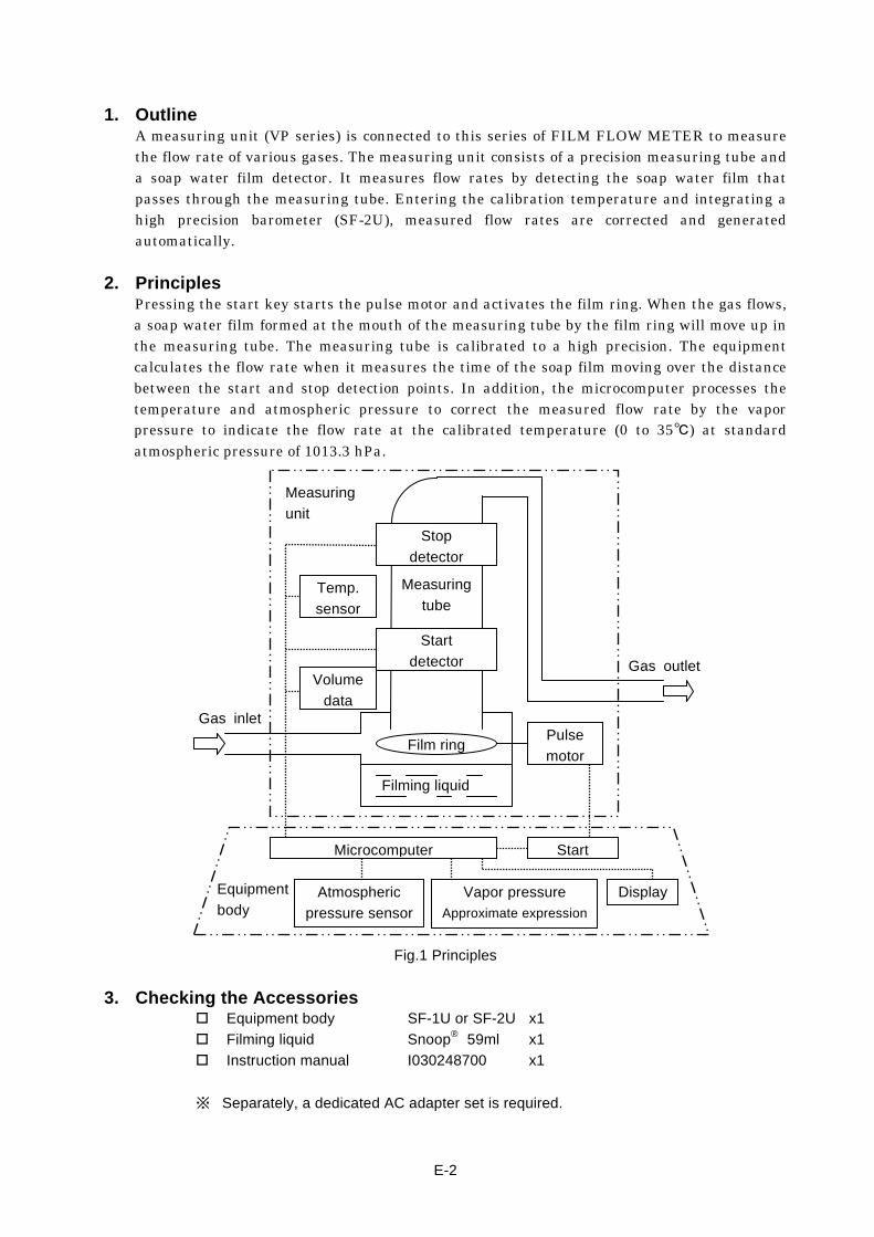
1. Outline
A measuring unit (VP series) is connected to this series of FILM FLOW METER to measure the flow rate of various gases. The measuring unit consists of a precision measuring tube and a soap water film detector. It measures flow rates by detecting the soap water film that passes through the measuring tube. Entering the calibration temperature and integrating a high precision barometer (SF-2U), measured flow rates are corrected and generated automatically.
2. Principles Pressing the start key starts the pulse motor and activates the film ring. When the gas flows, a soap water film formed at the mouth of the measuring tube by the film ring will move up in the measuring tube. The measuring tube is calibrated to a high precision. The equipment calculates the flow rate when it measures the time of the soap film moving over the distance between the start and stop detection points. In addition, the microcomputer processes the temperature and atmospheric pressure to correct the measured flow rate by the vapor pressure to indicate the flow rate at the calibrated temperature (0 to 35℃) at standard atmospheric pressure of 1013.3 hPa.
Fig.1 Principles
3. Checking the Accessories Equipment body SF-1U or SF-2U x1
Filming liquid Snoop® 59ml x1
Instruction manual I030248700 x1
※ Separately, a dedicated AC adapter set is required.
Temp.
sensor
Volume
data
Pulse
motorFilm ring
Measuring
tube
Measuring
unit
Filming liquid
Gas inlet
Gas outlet
Microcomputer
Atmospheric
pressure sensor
Vapor pressure
Approximate expression
Start
Display
Stop
detector
Start
detector
Equipment
body

E-3
4. Specifications
Name FILM FLOW METER Model SF-1U/SF-2U
Measuring unit model VP-1U VP-2U VP-3U VP-4U Nominal volume 0.4 ml 2 ml 20 ml 200 ml
Flow rate measurement range
0.2~10 ml/min 2~100 ml/min 20~1000 ml/min 0.2~10 L/min
Measurement time 120~2.4 sec 60~1.2 sec 60~1.2 sec 60~1.2 sec Accuracy ±0.5% 0.2~2 ml/min 2~20 ml/min 20~200 ml/min 0.2~1 L/min
±1.0% 2~10 ml/min 20~100 ml/min 200~1000 ml/min 1~10 L/minRepeatability ±0.2% 0.2~2 ml/min 2~20 ml/min 20~200 ml/min 0.2~1 L/min
±0.5% 2~10 ml/min 20~100 ml/min 200~1000 ml/min 1~10 L/min
Applicable gases N2, Air, O2, H2, He, Ar, CO, CH4, C3H8 and other similar gases. Note: Not applicable to water-soluble or corrosive gases
Setting range of atmospheric pressure
730~1070hPa (For SF-2U, at the manual atmospheric pressure data entry mode.)
Range of atmospheric pressure measurement
(SF-2U)
930~1040hPa Accuracy :±2.7hPa (Measured data can be used for correction. When used for correction, overall accuracy becomes ±0.7% from ±0.5% and ±1.2% from ±1.0%, respectively.)
Display LCD 6-digit digital display. (Readings are switched among measured flow rate, measurement time, temperature, atmospheric pressure and other data.)
Automatic measurement function
Takes 2 to 10 measurements and calculates mean values automatically in AUTO mode. (Previous data can be stored and called up. Data is gone when equipment is turned off.)
Power source DC 7V 0.5A Dedicated AC adapter Ambient operating
temperature 5~40°C Accuracy is guaranteed between 15 to 35°C.
Ambient operating humidity Less than 80% (no condensation) Indoor/Outdoor usage Indoor use only
Corrective function
Data correction by temperature, atmospheric pressure and vapor pressure to generate flow rates at calibration temperature and standard atmospheric pressure (1,013.3 hPa). Calibration temperature can be set to O to 35°C.
External data input/output RS-232C-compliant
Weight Approx. 2.1kg Approx. 2.7kg
External dimension W140mm x H287.6mm x D200mm W140mm x H457.6mm
x D200mm
Applicable standards EMC DIRECTIVE EN61326-1 class B

E-4
5. Description of each part
Fig.2 Description of each part
①
②③
④
⑤ ⑥
⑦
⑫
⑭
⑮ ⑯
⑰
⑧⑨
⑩
⑪
⑬

E-5
① Measurement gas inlet Hose connection to measurement gas. And this is also used for pouring or draining filming liquid.6.1.4,6.1.5
② Measurement gas outlet Hose connection for exhausting measurement gas.6.1.5
③ Liquid level window For monitoring level of filming liquid.⇒6.1.4
④ Start detector Film detector for starting time measurement.
⑤ Stop detector Film detector for stopping time measurement.
⑥ Measuring tube window For monitoring measuring tube in order to check the condition of film or dirt inside the tube.
⑦ Film removal paper port Port for putting in paper to remove liquid or film.6.1.5
⑧ Signal connector (SERIAL)
For connecting printer or control signals by PC. The optional dedicated cable is needed to connect printer or PC.
⑨ Power connector(DC7VIN) Connector for dedicated AC adapter.⇒ 6.1.2
⑩ Power switch (POWER) Switch for turning on/off.6.1.7
⑪ Fixing lever Lever for fix/release the measuring unit.6.1.3
⑫ Display
Flow rate Significant digit: 4 digits Unit selection: 999.9 ml/min or less - unit in ml/min
1000 ml/min or more - unit in ml/min Mode display: Normal measurement d-:
Automatic measurement d※:
(※shows number of counts of automatic measurement. 2~A, “A” means 10times)
Temperature Significant digit: Significant digit:1st decimal place Operation: Real time display
(No hold when measurement is completed.) Display range: 5.0~40.0°C
(Temperature accuracy guaranteed 15~35℃) Mode display: 「1: ※※.※℃
Timing Significant digit: 4 digits
Atmospheric pressure
Significant digit: Significant digit:1st decimal place Operation: Real time display
(No hold when measurement is completed.) Display range 730 to 1070 hPa (Range of atmospheric pressure
measurement: 930 to 1040 hPa) Mode display: Manual input H.※※※※.※hPa
Atmospheric pressure measurement A.※※※※.※hPa(SF-1U has only manual input function.)
Alarm A1:---- Start detector detects abnormality.⇒8.2 A2:---- Stop detector detects abnormality.⇒8.3 A3:---- Detector luminous energy is low.⇒8.4 A4:---- Voltage is low.⇒8.5 A1:---A Automatic wetting error⇒8.2
Calibration temperature
「0: ※※.※ (※ shows calibration temperature.)⇒6.1.6 Significant digit: 1st decimal place. Range setting: 0~35.0°C
Miscellaneous Automatic measurement count
AU:__※※(※shows measurement count 02 to 10.)Display only when automatic measurement count is entered.⇒6.2.3
Automatic wetting operation
dP:---- ⇒6.2.1
Alarm time setting
A1: ※※※sec A1 alarm time setting A2: ※※※sec A2 alarm time setting (※ shows time setting. )⇒6.4,8.2, 8.3
⑬ Unit indicator LED indicates the unit of value display shows.
⑭ SET key For various settings and calling up automatic measurement data.
⑮ SELECT key For selecting display and set items.
⑯ AUTO key For selecting automatic measurement mode. Automatic measurement mode is ready when LED on this key is lighted.⇒6.2.3
⑰ START key Besides starting measurement/automatic measurement, this includes functions such as alarm reset, measurement stop and automatic wetting.

E-6
6. Operating Instructions
6.1. Preparation
6.1.1. Measurement site
NOTE The following areas are not appropriate for measurement.
Areas where the floor is not level. Areas where exposed to direct sun rays. Areas where the temperature varies
quickly. Areas close to cooling/heating devices. Areas exposed to vibrations.
Areas with forced air intake or exhaust. Areas where condensation occurs or
getting wet. Windy areas. Chambers where the doors are
open/closed frequently.
REF. To ensure precision flow rate measurement, use the equipment in an isothermal chamber installed in an air-conditioned room.
6.1.2. Power connection
Connect the dedicated AC adapter and the power cable. Put the AC adapter plug into the power connector at the back of the equipment. Connect the AC adapter to an appropriate power outlet.
WARNING
USE DEDICATED AC ADAPTER. Using an inappropriate AC adapter may cause damage or injury through fire or electric shock.

E-7
6.1.3. Installing measuring unit
① Install the measuring unit (VP-1U-VP-4U) suitable for the intended flow rate measurement as follows. Align hook pin on the equipment with the groove on the measuring unit to insert.
② Turn the fixing lever to the direction arrow in Fig.3 to complete the installation. ※ when you uninstall the measuring unit, turn the fixing lever to the original position.
Then pull up the measuring unit gently while holding the SF main body.
CAUTION
BE SURE TO FIX MEASURING UNIT. Make sure that the measuring unit is fixed to the main body by turning the fixing lever when you install. Carrying or using them without fixing may cause damage or injury through dropping or turning over
Fig.3 Installing measuring unit Fig.4 Pouring filming liquid
6.1.4. Pouring filming liquid
Put the nozzle of filming liquid bottle, 2 cm to 3 cm, into the measurement gas inlet port on the left side of the measuring unit. Fill the equipment with filming liquid gradually up to the liquid level, between 2 blue lines on the liquid level window. Be sure not to create bubbles.
NOTE Do not put the nozzle more than 4 cm into the measuring unit. It will be
cause of a trouble. Be sure to use the designated filming liquid Snoop®. Use of other soap
water not only causes inadequate filming but contaminates the measuring unit and deteriorates the packing.
Be sure the liquid level is always between two blue lines when you measure. The liquid level above or below the upper and lower levels adversely affect the film creation and measurement accuracy.
①
② Groove
Hook pin
Filming
liquid
Snoop®
Connector

E-8
6.1.5. Piping
① Connect the tube to the measurement gas inlet. VP-1U~3U:Outer diameter 6 mm hose connector (For soft tube of inner diameter 5-6 mm)
VP-4U:Outer diameter 10 mm hose connector (For soft tube of inner diameter 9-10 mm)
② Connect the tube to the measurement gas outlet. Outer diameter 10 mm hose connector (For soft tube of inner diameter 9-10 mm)
WARNING
DO NOT LET REACTIVE GAS FLOW. Do not let reactive gas that react with water or oxygen. This equipment doesn’t have a perfect gas sealing. Besides, it uses liquid for filming. Letting reactive gas flow may cause damage or injury through fire or explosion.
LEAD GAS TO SAFE PLACE. Make an exhaust line to a safe place. Otherwise an explosion or other hazards may happen.
NOTE While the measurement gas should go through heat exchange process
with the measurement ambient temperature. The difference between the measurement gas temperature and the measurement ambient temperature adversely affects the film creation and measurement accuracy.
The measuring gas has to be saturated with vapor when the intended flow rate is over 3L/min. The dry gas causes not only drying the volume tube, but an inaccurate result.
Stop the gas flow when you don’t measure. Otherwise, the inside of the measuring tube may be contaminated.
REF. The tube should be as short as possible. This is to reduce the gas volumetric changes due to minute changes in the temperature.
If you exhaust the measuring gas by drafting, be careful for the pressure of measurement gas not to drop.
When measuring a minute amount of flow rate, use a reducer or a similar device so that the tube diameter can be as small as possible.(For the gas inlet only)
A more correct result can be obtained if the measuring gas is humidified enough before the measuring unit.
③ Put a piece of film removal paper, about 2 cm from the tip, in its port. This is to reduce measurement time. (For VP-1U,2U only) ※ The film removal paper should be made by twisting a piece of paper with water
absorptivity. Its diameter should be 1 to 2 mm.
NOTE Do not put film removal paper over 2 cm. Otherwise, it blocks the passage
of the gas, and causes an inaccurate result. Replace film removal paper often. The passage may be tight when the
paper expands and this causes an inaccurate result. Be sure to use the rubber cap whenever measuring flow rates.
E-9
6.1.6. Setting calibration temperature
Set to 25℃ at the factory: The calibration temperature is set to correct the measured flow rate to the value at the calibration temperature. For example, set this value to "25℃" when calibrating a flow meter designed for one atmospheric pressure. Follow the setting procedure below:
① While pressing the SET key “△”, turn on the power switch. Hold down the SET key “△ ” for five seconds. The equipment will be ready for setting the calibration temperature.
② Use the SET keys to enter the calibration temperature. The temperature range is 0 to 35℃. Pressing the SET keys (“△”,”▽”) simultaneously sets the temperature to the initial value of 25.0℃.
③ Turn off the power switch to secure the entry. The equipment stores the settings even after turning off the power.
※ The calibration temperature can be checked by following two ways. Turn on the power switch. Then the display will show it after the version
number. (Approx. 3sec. ) Press the SET key “△” or”▽” when the display is showing the temperature.
This operation is not available at Automatic measurement mode.
6.1.7. Turning on the power switch
The version number and the calibration temperature will be on the display just after turning on the power switch. Both of them are shown for approx. 3sec.
NOTE Make sure the calibration temperature setting is correct. If the setting is
incorrect, you cannot obtain correct results. Warm up the equipment for over 10 minutes after turning on the power. If
the sensors are not stable, you cannot obtain correct results.
E-10
6.2. Measurement
6.2.1. Wetting inside measuring tube
In the beginning of operation, liquid films break in the middle of the process because the interior walls of the measuring tube are dry. In the manual/auto mode, let the measurement gas or inert gas such as N2 flow so that the films wet the interior walls of the measuring tube. Note that the wetting operation may be necessary even during the measurement if the equipment is left for a while without creating films.
REF. Wetting will be smoothly done with the gas flow 5 to 20 percent of full scale of the measuring unit.
Manual wetting operation ① Press the START key for several times to several tens of times with intervals over one
second. ② Watch the condition of films through the measuring tube window while doing above
operation. ③ Stop pressing the Start key after films reaches the Stop detector. Then wait for a while
until all the films pass the stop detector. Automatic wetting operation
① Press the START key for one second or longer. ② Indication dP:---- appears on the display. Then, the equipment creates films
automatically for approximately every four seconds. ③ This operation will be finish after films reaches the Stop detector.
※ When operated during waiting: Stops when a short "pip" sound is heard. ※ When operated during measurement: Present measurement continues.
NOTE Make sure that there is no film inside the measuring tube before pressing
the START key for measuring. If there are films inside the measuring tube, it causes an inaccurate result.
6.2.2. Entering atmospheric pressure
For SF-1 ① Use the SELECT key to have the display ready for data entry ("hPa" stays lit on the
display). ② Operate the SET keys to set the atmospheric pressure. (Setting range: 730~1070hPa)
To enter 1013.3 hPa, press the SET keys (“△”,”▽”) simultaneously.
For SF-2 Since the integrated barometer enters the atmospheric pressure, no data entry is normally necessary. For manual data entry, however, follow the procedure below. ① Use the SELECT key to have the display ready for data entry ("hPa" stays lit on the
display). ② Press the SET keys (“△”,”▽”) simultaneously for two seconds or longer. ③ The equipment will enter the manual atmospheric pressure data entry mode.
Data display A ⇒ H ,Unit display (hPa) Staying lit ⇒ Flashing ④ Use the SET keys to enter the data. (Setting range: 730~1070hPa)
To enter the initial value of 1013.3 hPa, press the SET keys (“△”,”▽”) simultaneously. ※ Note that if pressed for two seconds or longer, the manual mode will be reset.
NOTE Make sure the setting of atmospheric pressure is correct. If the setting is
not correct, it causes an inaccurate result.

E-11
6.2.3. Measurement
This equipment has two ways to have measurements, normal measurement and automatic measurement. Certain numbers of measurement will carry out automatically, and you can get the results for each measurement and their average by automatic measurement.
Normal measurement
① Press the START key to start measurement. ② The display will be flashing until a film reaches to the start detector.
0.000
③ Counts up the elapsed time from when the film passes the start detector. 0.123
④ After indicating the duration of the time between the film passing the start detector and it being detected by the stop detector, the flow rate appears on the display.
1.234 Time ⇒ d-:10.23 Flow rate ⑤ Press the SELECT key to switch the indications to check the measurement data. The
following data items appear on the display every time the key is pressed. Flow rate ⇒ Temperature ⇒Measurement time
⇒Atmospheric pressure ⇒Flow rate ⇒・・・ ※ Note, however, that the temperature and atmospheric pressure are displayed on
real time basis. ※ The flow rate will remain until the following measurement starts. ※ Temperatures and atmospheric pressures are sampled when the stop detector
detects the liquid films.
Automatic measurement ① Press the AUTO key once. to enter. ("AUTO" lights up.) ② The indicator on the AUTO key will light up. And the automatic measurement mode /
measurement count setting mode starts. ③ Use the SET keys to enter the frequency of automatic measurement (2 to 10 times).
AU: ※※ ※shows the number,02~10. ④ Press the START key to start the automatic measurement. ⑤ Warm-up measurement will be carried out once just after starting. Its results will be
invalid. The display shows the number of frequency by”※-”. (※shows the number. And “A” means 10 times.) Except for this, the display will be as same as the one on Normal measurement.
⑥ The buzzer will sound intermittently when the measurement completed. ⑦ Press the SET key to check the measured flow rates after completing the automatic
measurement. The display shows ”d0” for the average. “d1”~”d9” shows 1~9 times. “dA” shows 10 times. Press the SET keys to check the measured data for each measurement event.
※ To abort the automatic measurement in the midway, press the START key while holding the SELECT key.
※ The waiting time between two consecutive measurement events is one quarter of the preceding measurement time while the minimum and maximum are 3 and 10 seconds respectively.
※ To reset the automatic measurement mode, press the AUTO key. The indicator on the AUTO key will go out.
E-12
※ When checking the automatic measurement results after resetting the automatic measurement mode, press the AUTO key twice to enter the automatic measurement mode/data call-up. (The indicator on the AUTO key flashes.) Then, follow the procedures as described in ⑦ above.
※ The measured data will be stored in the memory until the next automatic measurement event takes place or the power is turned off.
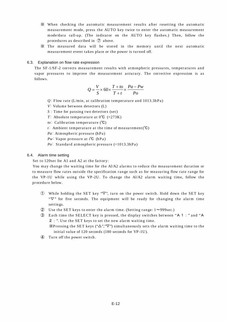
6.3. Explanation on flow rate expression
The SF-1/SF-2 corrects measurement results with atmospheric pressures, temperatures and vapor pressures to improve the measurement accuracy. The corrective expression is as follows.
Po
PwPa
tT
toT
S
VQ
60
Q: Flow rate (L/min, at calibration temperature and 1013.3hPa) V: Volume between detectors (L) S:Time for passing two detectors (sec) T: Absolute temperature at 0℃ (=273K) to: Calibration temperature (℃) t: Ambient temperature at the time of measurement(℃) Pa: Atmospheric pressure (hPa) Pw: Vapor pressure at t℃ (hPa) Po: Standard atmospheric pressure (=1013.3hPa)
6.4. Alarm time setting
Set to 120sec for A1 and A2 at the factory: You may change the waiting time for the Al/A2 alarms to reduce the measurement duration or to measure flow rates outside the specification range such as for measuring flow rate range for the VP-1U while using the VP-2U. To change the Al/A2 alarm waiting time, follow the procedure below.
① While holding the SET key “▽”, turn on the power switch. Hold down the SET key “▽” for five seconds. The equipment will be ready for changing the alarm time settings.
② Use the SET keys to enter the alarm time. (Setting range: 1~999sec.) ③ Each time the SELECT key is pressed, the display switches between “A1:” and “A
2:”. Use the SET keys to set the new alarm waiting time. ※Pressing the SET keys (“△”,”▽”) simultaneously sets the alarm waiting time to the
initial value of 120 seconds (180 seconds for VP-1U). ④ Turn off the power switch.
E-13
7. MAINTENANCE 7.1. Daily maintenance
7.1.1. Replenishing filming liquid
Fill the measuring unit with filming liquid while checking the liquid level through the liquid level window.⇒6.1.4
7.1.2. Replacement of filming liquid
If the filming liquid is contaminated or it has difficulty in creating .liquid films, replace the filming liquid promptly. Tilt the measuring unit side way to drain the filming liquid.⇒6.1.4
7.1.3. Cleaning measuring tube
If the measuring tube is contaminated, follow the procedure below to clean it. ① Drain the filming liquid from the gas inlet. ② Connect a piece of vinyl tube, longer than measuring unit height, to the gas inlet
port. ③ Raise the end of a vinyl tube, and pour in clean water until the water reaches the
stop detector. In case inside the measuring tube is too dirty, use a neutral detergent ④ Leave for a while. Drain the detergent in the same manner as draining the filming
liquid. ⑤ Rinse the measuring tube thoroughly with clean water. ⑥ Remove the vinyl tube. Fill the equipment with filming liquid after drying inside the
measuring tube.⇒6.1.4 7.2. Periodical maintenance
Periodical maintenance, accuracy inspection and re-calibration are available with an extra cost so that your SF-1/SF-2 operates correctly and accurately. It is recommended that the volume value and atmospheric pressure value should be inspected every year. Consult HORIBA STEC,CO.,LTD. or your dealer for quotation and other details.
7.2.1. Parts replacement frequencies
When to replace certain parts depends on the operating frequencies and measurement fluids. The following parts replacement schedule and frequencies are recommended as a guideline.
Pulse motor assembly 2 years
Filming unit assembly 2 years
Seal kit 2 years or when disassembled
Internal piping 3 years
Other parts As required
7.2.2. Maintenance parts list
Filming liquid Snoop® 236ml No.S000025(3024000025)
Dedicated AC adapter set PS-SF-100C(for Japan) No.S242802(3200496396)
Dedicated AC adapter (for Europe)
Please consult to our company at the time of a necessity.
Dedicated AC power cord (for Europe)
Please consult to our company at the time of a necessity.

E-14
8. Troubleshooting
If the equipment does not operate correctly, go through the following procedure as much as possible before contacting HORIBA STEC,CO.,LTD. services so that HORIBA STEC,CO.,LTD. is able to provide you with quick service.
8.1. The equipment is not turned on
Power is not turned on.
Check the power source. Abnormal
Normal Power supply
Abnormal Check AC adapter
and connectors.
Plug in again Normal
※Check, repeair
or replace wiring,
or circuit board.
Items marked with “※” are services from HORIBA STEC,CO.,LTD. or your dealer. Placing order for the services is recommended.

E-15
8.2. A1 alarm
(Detecting start detector errors)
A1 alarm generated
Check filming condition Abnormal
Abnormal
Normal Check filming operation
Abnormal
Check measured flow rate
Normal ※Repair
Replace VP Normal
Check filming Abnormal
Abnormal liquid level
Check alarm time Adjust
Normal liquid level
Set time
Normal Check filming liquid Abnormal
for contamination
Replace
Normal filming liquid
Abnormal Check measuring tube
for contamination
Clean measuring tube Normal
※Check, repair or overhaul
detector
Items marked with “※” are services from HORIBA STEC,CO.,LTD. or your dealer. Placing order for the services is recommended.
A1 alarm (A1:----) This alarm is generated if the time from film creation to its detection by the start detector takes more than 120 seconds (180 seconds for VP-1U) due to film breakage or attempting to measure a flow rate outside the specification range. Wet inside measuring tube and check the flow rate attempting to measure. The alarm time (120 or 180 seconds) can be changed. ⇒6.4
Automatic wetting operation alarm (A1:---A) This alarm is generated if the interior walls of the measuring tube do not get wet in 120 seconds after starting the automatic wetting operation. Check the flow rate attempting to measure and the filming liquid level. The alarm time (120 seconds) can be changed. ⇒6.4 (Common to the A1 alarm) Cleaning measuring tube. ⇒7.1.3 Press the START key to reset the alarm.

E-16
8.3. A2 alarm
(Detecting stop detector errors)
A2 alarm generated
Check filming condition Abnormal
Abnormal
Normal Check filming operation
Abnormal
Check measured flow rate
※Repair
Replace VP Normal Normal
Abnormal Check filming liquid Abnormal
Check alarm time for contamination
Set time Normal Replace
Normal filming liquid
Abnormal Check measuring tube
for contamination
Clean measuring tube Normal
※Check, repair or overhaul
detector
Items marked with “※” are services from HORIBA STEC,CO.,LTD. or your dealer. Placing order for the services is recommended.
A2 Alarm (A2:----) A stop detector error occurs. It is generated if the time from the film detection by the start detector to the film detection by the stop detector takes more than 120 seconds (180 seconds for VP-1U) due to film breakage or attempting to measure a flow rate outside the specification range. Wet inside measuring tube and check the flow rate attempting to measure. The alarm time (120 or 180 seconds) can be changed.⇒6.4 Cleaning measuring tube.⇒7.1.3
Press the START key to reset the alarm.
E-17
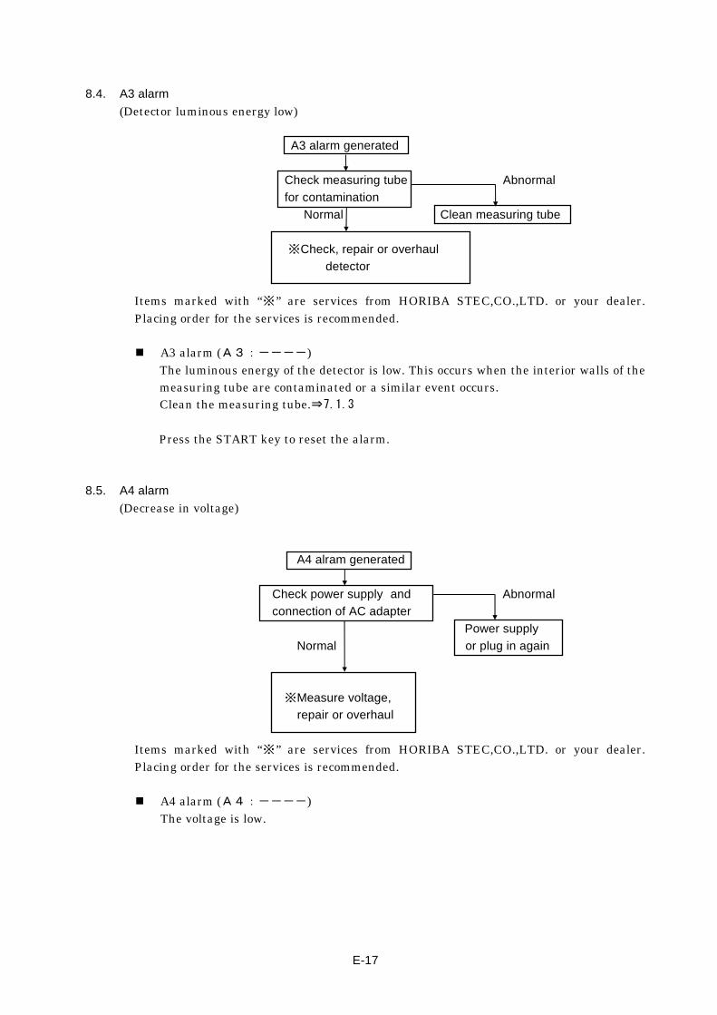
8.4. A3 alarm
(Detector luminous energy low)
A3 alarm generated
Check measuring tube Abnormal
for contamination
Normal Clean measuring tube
※Check, repair or overhaul
detector
Items marked with “※” are services from HORIBA STEC,CO.,LTD. or your dealer. Placing order for the services is recommended.
A3 alarm (A3:----) The luminous energy of the detector is low. This occurs when the interior walls of the measuring tube are contaminated or a similar event occurs. Clean the measuring tube.⇒7.1.3
Press the START key to reset the alarm.
8.5. A4 alarm
(Decrease in voltage)
A4 alram generated
Check power supply and Abnormal
connection of AC adapter
Power supply
Normal or plug in again
※Measure voltage,
repair or overhaul
Items marked with “※” are services from HORIBA STEC,CO.,LTD. or your dealer. Placing order for the services is recommended.
A4 alarm (A4:----) The voltage is low.

E-18
8.6. More than one film are created
More than one film are created
Abnormal Checking filming
liquid level
Adjust Normal
liquid level
※Check, adjust, overhaul or replace
filming mechanism or measuring tube
Items marked with “※” are services from HORIBA STEC,CO.,LTD. or your dealer. Placing order for the services is recommended.
8.7. Clock does not work
Clock count abnormality
Abnormal Check filming liquid
for contamination
Adjust Normal
liquid level
Check measuring tube Abnormal
for contamination
Normal Clean measuring tube
※Check, repair or overhaul
detector
Items marked with “※” are services from HORIBA STEC,CO.,LTD. or your dealer. Placing order for the services is recommended.
Clean the measuring tube.⇒7.1.3
E-I
APPENDIX A Computer communication specifications
With the SF-1 or SF-2 connected to the host computer (CPU) with a cable dedicated to RS-232C data communication, automatic flow rate measurement can be controlled by a computer program.
1. Connection
1.1. Hardware specifications (RS-232C-compliant)
① Pacing synchronization (asynchronous) system ② Data bit 8bits/1character ③ Stop bit 2bits ④ Parity NON
1.2. Setting the baud rate
Set to 9600bps at the factory: Follow the procedure below to set the baud rate of the SF main unit. ① While holding the AUTO key, turn on the power switch. Hold down the AUTO key for
five seconds. The equipment is ready for setting the baud rate. ② While checking the display, use the SET keys to enter the selection. The baud rate can
be selected from either 9600, 4800, 2400 and 1200 bps. ③ Turn off the power switch.
1.3. Starting up
After connecting the equipment to the host computer (CPU) with the dedicated communication cable, turn on the equipment. This makes operable the remote control of the equipment from the host computer (CPU).
1.4. Dedicated communication cable
Use following cable:※
SF CABLE Type: SC-NSF-PCV (2m) No. S089362(3024059056)
Maker: HORIBA STEC,CO.,LTD.
※Specifications are different from the commercial RS-232C crossing cable .
E-II
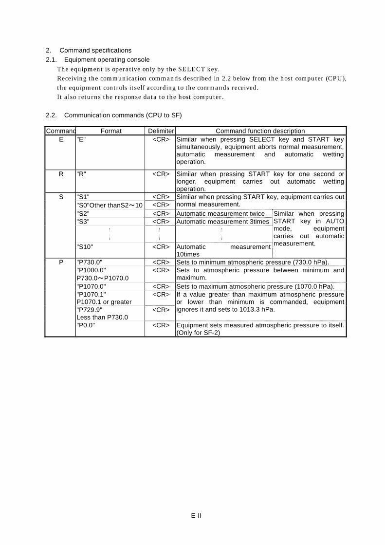
2. Command specifications
2.1. Equipment operating console
The equipment is operative only by the SELECT key. Receiving the communication commands described in 2.2 below from the host computer (CPU), the equipment controls itself according to the commands received. It also returns the response data to the host computer.
2.2. Communication commands (CPU to SF)
Command Format Delimiter Command function description E "E" <CR> Similar when pressing SELECT key and START key
simultaneously, equipment aborts normal measurement, automatic measurement and automatic wetting operation.
R "R" <CR> Similar when pressing START key for one second or longer, equipment carries out automatic wetting operation.
S "S1" <CR> Similar when pressing START key, equipment carries out normal measurement. "S0"Other thanS2~10 <CR>
"S2" <CR> Automatic measurement twice Similar when pressing START key in AUTO mode, equipment carries out automatic measurement.
"S3" <CR> Automatic measurement 3times⋮ ⋮
⋮ ⋮
⋮ ⋮
"S10" <CR> Automatic measurement 10times
P "P730.0" <CR> Sets to minimum atmospheric pressure (730.0 hPa). "P1000.0" P730.0~P1070.0
<CR> Sets to atmospheric pressure between minimum and maximum.
"P1070.0" <CR> Sets to maximum atmospheric pressure (1070.0 hPa). "P1070.1" P1070.1 or greater
<CR> If a value greater than maximum atmospheric pressure or lower than minimum is commanded, equipment ignores it and sets to 1013.3 hPa. "P729.9"
Less than P730.0 <CR>
"P0.0" <CR> Equipment sets measured atmospheric pressure to itself. (Only for SF-2)

E-III
2.3. Communication commands (SF to CPU)
※Make the host computer ready to receive commands all the time.
① When a normal or automatic measurement event in response to S commands is completed normally: The equipment returns measurement results in following order.
Order Format Delimiter Response data description
1
"FRML123.4" <CR> Normal measurement Measurd flow rate of less than 1L/min Position of decimal point in each flow rate range: 0.000~9.999ml/min 10.00~99.99ml/min 100.0~999.9ml/min ※ The colon “:” is a data
delimiter. First data shows mean value followed by data of each measurement event from first to tenth.
"FRML123.4:123.4:123.4" <CR> Two automatic measurement
"FRML123.4:123.4:123.4:123.4" <CR> Three automatic measurement
⋮ ⋮
⋮ ⋮
⋮ ⋮
"FRML123.4:123.4:123.4:123.4:123.4:123.4:123.4:123.4 :123.4:123.4:123.4"
<CR> Ten automatic measurement
"FRL1.234" <CR> Normal measurement Measurd flow rate of less than 1L/min Position of decimal point in each flow rate range: 1.000~9.999L/min 10.00~ L/min ※ The colon “:” is a data
delimiter. First data shows mean value followed by data of each measurement event from first to tenth.
"FRL1.234:1.234:1.234" <CR> Automatic measurement twice
"FRL1.234:1.234:1.234:1.234" <CR> Automatic measurement 3times
⋮ ⋮
⋮ ⋮
⋮ ⋮
"FRL123.4:123.4:123.4:123.4 :123.4:123.4:123.4:123.4 :123.4:123.4:123.4"
<CR> Automatic measurement 10times
2
"TIME12.54" <CR> Normal measurement Measurement duration Position of decimal point in each time range:
0.000~9.999sec 10.00~99.99 sec 100.0~999.9sec ※ The colon “:” is a data
delimiter. First data shows mean value followed by data of each measurement event from first to tenth.
"TIME12.54:12.54:12.54" <CR> Automatic measurement twice
"TIME12.54:12.54:12.54:12.54" <CR> Automatic measurement 3times
⋮ ⋮
⋮ ⋮
⋮ ⋮
"TIME12.54:12.54:12.54:12.54 :12.54:12.54:12.54:12.54 :12.54:12.54:12.54"
<CR> Automatic measurement 10times
3 "ST.T_25.0" <CR> Satndard calibration temprature
※”_” indicates blank. "ST.T__0.0" <CR>
4 "MJ.T_25.4" <CR> Measured temprature
※”_” indicates blank. "MJ.T__9.4" <CR>
5 "AT.P1070.0" <CR> Set atmospheric pressure
※”_” indicates blank. "AT.P_730.0" <CR>
Data formats for 1,2,3,4 and 5 above: 1 Depending on the frequency of automatic measurement and the range of measured flow
rate, the equipment selects from 1 and returns the data. 2 Depending on the frequency of automatic measurement and the range of measured flow
rate, the equipment selects from 2 and returns the data. 3 Depending on whether the calibration temperature is 10.0℃ or greater or less than
10.0℃, the equipment selects either 3 and returns the data. 4 Depending on whether the measured temperature is 10.0℃ or greater or less than
10.0℃, the equipment selects either 4 and returns the data. 5 Depending on whether the set atmospheric pressure is 1000.0 hPa or greater or less than
1000.0 hPa, the equipment selects from 5 and returns the data.
E-IV
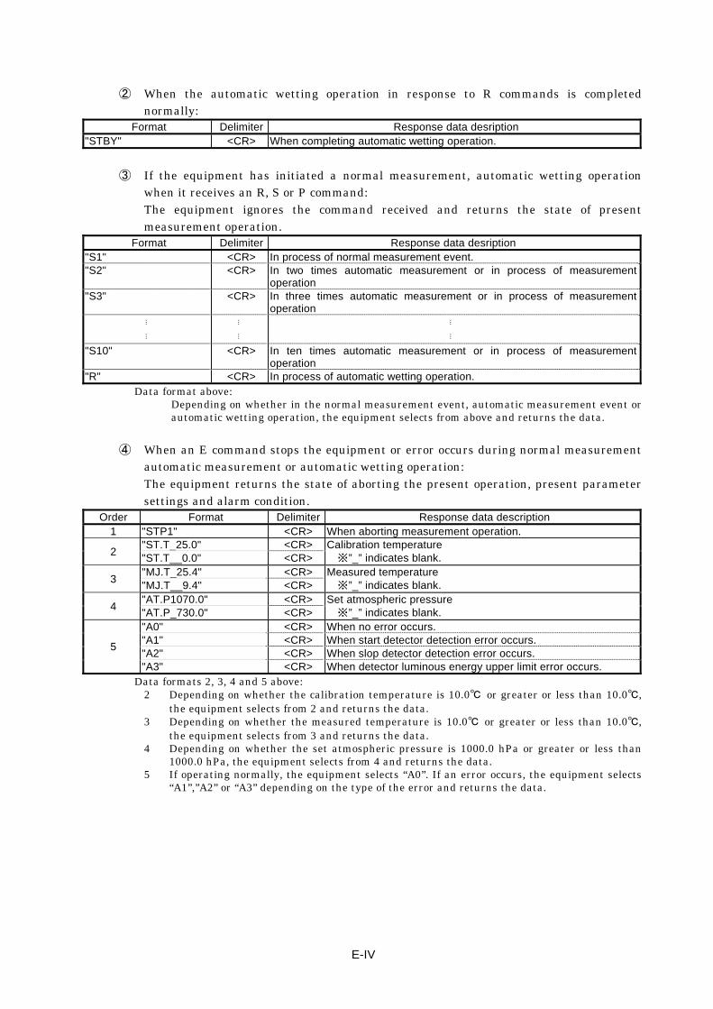
② When the automatic wetting operation in response to R commands is completed normally:
Format Delimiter Response data desription "STBY" <CR> When completing automatic wetting operation.
③ If the equipment has initiated a normal measurement, automatic wetting operation when it receives an R, S or P command: The equipment ignores the command received and returns the state of present measurement operation.
Format Delimiter Response data desription "S1" <CR> In process of normal measurement event. "S2" <CR> In two times automatic measurement or in process of measurement
operation "S3" <CR> In three times automatic measurement or in process of measurement
operation ⋮ ⋮
⋮ ⋮
⋮ ⋮
"S10" <CR> In ten times automatic measurement or in process of measurement operation
"R" <CR> In process of automatic wetting operation. Data format above:
Depending on whether in the normal measurement event, automatic measurement event or automatic wetting operation, the equipment selects from above and returns the data.
④ When an E command stops the equipment or error occurs during normal measurement
automatic measurement or automatic wetting operation: The equipment returns the state of aborting the present operation, present parameter settings and alarm condition.
Order Format Delimiter Response data description 1 "STP1" <CR> When aborting measurement operation.
2 "ST.T_25.0" <CR> Calibration temperature
※”_” indicates blank. "ST.T__0.0" <CR>
3 "MJ.T_25.4" <CR> Measured temperature
※”_” indicates blank. "MJ.T__9.4" <CR>
4 "AT.P1070.0" <CR> Set atmospheric pressure
※”_” indicates blank. "AT.P_730.0" <CR>
5
"A0" <CR> When no error occurs. "A1" <CR> When start detector detection error occurs. "A2" <CR> When slop detector detection error occurs. "A3" <CR> When detector luminous energy upper limit error occurs.
Data formats 2, 3, 4 and 5 above: 2 Depending on whether the calibration temperature is 10.0℃ or greater or less than 10.0℃,
the equipment selects from 2 and returns the data. 3 Depending on whether the measured temperature is 10.0℃ or greater or less than 10.0℃,
the equipment selects from 3 and returns the data. 4 Depending on whether the set atmospheric pressure is 1000.0 hPa or greater or less than
1000.0 hPa, the equipment selects from 4 and returns the data. 5 If operating normally, the equipment selects “A0”. If an error occurs, the equipment selects
“A1”,”A2” or “A3” depending on the type of the error and returns the data.
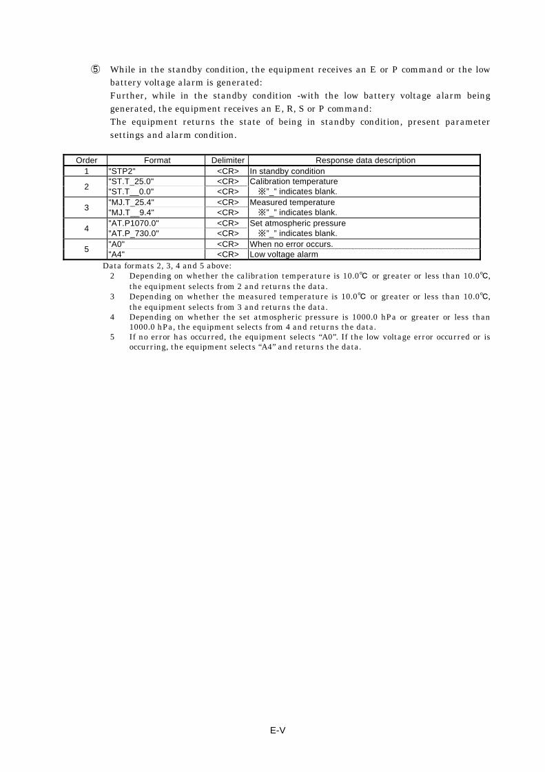
E-V
⑤ While in the standby condition, the equipment receives an E or P command or the low battery voltage alarm is generated: Further, while in the standby condition -with the low battery voltage alarm being generated, the equipment receives an E, R, S or P command: The equipment returns the state of being in standby condition, present parameter settings and alarm condition.
Order Format Delimiter Response data description 1 "STP2" <CR> In standby condition
2 "ST.T_25.0" <CR> Calibration temperature
※”_” indicates blank. "ST.T__0.0" <CR>
3 "MJ.T_25.4" <CR> Measured temperature
※”_” indicates blank. "MJ.T__9.4" <CR>
4 "AT.P1070.0" <CR> Set atmospheric pressure
※”_” indicates blank. "AT.P_730.0" <CR>
5 "A0" <CR> When no error occurs. "A4" <CR> Low voltage alarm
Data formats 2, 3, 4 and 5 above: 2 Depending on whether the calibration temperature is 10.0℃ or greater or less than 10.0℃,
the equipment selects from 2 and returns the data. 3 Depending on whether the measured temperature is 10.0℃ or greater or less than 10.0℃,
the equipment selects from 3 and returns the data. 4 Depending on whether the set atmospheric pressure is 1000.0 hPa or greater or less than
1000.0 hPa, the equipment selects from 4 and returns the data. 5 If no error has occurred, the equipment selects “A0”. If the low voltage error occurred or is
occurring, the equipment selects “A4” and returns the data.

E-VI
APPENDIX B Printer communication specifications
With the SF-1 or SF-2 connected to a dedicated printer with a dedicated cable, the results can be printed out.
1. Connection
1.1. Printer specifications (RS-232C-compliant)
① Pacing synchronization (asynchronous) system ② Data bit 8bits/1character ③ Stop bit 2bits ④ Parity NON
1.2. Setting the baud rate
Set to 9600bps at the factory: Follow the procedure below to set the baud rate of the SF main unit. ① While holding the AUTO key, turn on the power switch. Hold down the AUTO key for
five seconds. The equipment is ready for setting the baud rate. ② While checking the display, use the SET keys to enter the selection. The baud rate can
be selected from either 9600, 4800, 2400 and 1200 bps. ③ Turn off the power switch.
1.3. Starting up
After connecting the equipment to the printer with the dedicated communication cable, turn on the equipment. This makes printable the results by the printer.
1.4. Dedicated printer
Use following printer: ※Please consult about the exclusive cable of an option to our company at the time of a necessity. Impact Printer Type: CBM-910II-24RxxxxA
Maker: CITIZEN SYSTEMS JAPAN CO., LTD.

E-VII
2. Printing out specifications
Following measured datas will be printed out when the measurement is completed. Print format (Normal measurement)
Ex.1 Ex.2 **** STD.TEMP 25.0 ゚ C** **** STD.TEMP 0.0 ゚ C** **** Ordinal**** Ordinal FLOW RATE 1.984 l/min FLOW RATE 1.984 ml/min TEMPERATURE 24.8 ゚ C TEMPERATURE 9.9 ゚ C AT.PRESSURE 1013.0hPa AT.PRESSURE 1013.0hPa TIME 1.009 sec TIME 1.009 sec
Print format (Automatic measurement) Ex.1 Ex.2 **** STD.TEMP 25.0 ゚ C** **** STD.TEMP 0.0 ゚ C** **** First time **** First time FLOW RATE 1.984 l/min FLOW RATE 1.984 ml/min TEMPERATURE 24.8 ゚ C TEMPERATURE 9.9 ゚ C AT.PRESSURE 1013.0hPa AT.PRESSURE 1013.0hPa TIME 1.009 sec TIME 1.009 sec **** Second time **** Second time FLOW RATE 1.984 l/min FLOW RATE 1.984 ml/min TEMPERATURE 24.8 ゚ C TEMPERATURE 9.9 ゚ C AT.PRESSURE 1013.0hPa AT.PRESSURE 1013.0hPa TIME 1.009 sec TIME 1.009 sec **** Third time **** Third time FLOW RATE 1.984 l/min FLOW RATE 1.984 ml/min TEMPERATURE 24.8 ゚ C TEMPERATURE 9.9 ゚ C AT.PRESSURE 1013.0hPa AT.PRESSURE 1013.0hPa TIME 1.009 sec TIME 1.009 sec
⋮ ⋮
⋮ ⋮ **** Tenth time **** Tenth time FLOW RATE 1.984 l/min FLOW RATE 1.984 ml/min TEMPERATURE 24.8 ゚ C TEMPERATURE 9.9 ゚ C AT.PRESSURE 1013.0hPa AT.PRESSURE 1013.0hPa TIME 1.009 sec TIME 1.009 sec **** Average **** Average FLOW RATE 1.984 l/min FLOW RATE 1.984 ml/min TEMPERATURE 24.8 ゚ C TEMPERATURE 9.9 ゚ C AT.PRESSURE 1013.0hPa AT.PRESSURE 1013.0hPa TIME 1.009 sec TIME 1.009 sec
※ The unit of FLOW RATE changes depending on the result. Less than 1 L/min: “ml/min” More than 1 L/min: “l/min”
※ The numerical values printed out are as same as those LCD display shows. ※ Printing is carried out when the printer is “on line”.