INSTRUCTION MANUAL ENCLOSED MANUEL … · Unscrew 2 screws on the top edge of the frame. ......
32
ATTENTION IF YOU HAVE ANY PROBLEMS OR QUESTIONS, EMAIL OR CALL CUSTOMER SERVICE BEFORE YOU RETURN THIS PRODUCT TO THE STORE WHERE IT WAS PURCHASED. For Customer Service: email: [email protected] in English Call: 866-661-1218 in Spanish Call: 866-661-1218 in French Call: 866-374-9203 ATENCIÓN SI TIENE ALGÚN PROBLEMA O PREGUNTAS, ENVÍE UN MENSAJE DE CORREO ELECTRÓNICO O LLAME AL SERVICIO DE ATENCIÓN AL CLIENTE ANTES DE DEVOLVER ESTE PRODUCTO A LA TIENDA EN LA QUE LO COMPRÓ. Servicio de atención al cliente: Correo electrónico: [email protected] Línea para llamadas en inglés: 866-661-1218 Línea para llamadas en español: 866-661-1218 Línea para llamadas en francés: 866-374-9203 STOP STOP PARE PARE ATTENTION SI VOUS AVEZ DES PROBLÈMES OU DES QUESTIONS, ENVOYEZ UN COURRIEL AU SERVICE À LA CLIENTÈLE OU APPELEZ LE SERVICE À LA CLIENTÈLE AVANT DE RETOURNER CE PRODUIT OÙ VOUS L’AVEZ ACHETÉ. Pour le service à la clientèle : courriel : [email protected] pour le service en anglais, composez le 866-661-1218 pour le service en espagnol, composez le 866-661-1218 pour le service en français, composez le 866-374-9203 ARRÊT ARRÊT INSTRUCTION MANUAL ENCLOSED MANUEL D’INSTRUCTION À L’INTÉRIEUR MANUAL DE INSTRUCCIONES ADJUNTO INSTRUCTION MANUAL ENCLOSED MANUEL D’INSTRUCTION À L’INTÉRIEUR MANUAL DE INSTRUCCIONES ADJUNTO
Transcript of INSTRUCTION MANUAL ENCLOSED MANUEL … · Unscrew 2 screws on the top edge of the frame. ......

ATTENTIONIF YOU HAVE ANY PROBLEMS OR QUESTIONS, EMAIL OR CALL CUSTOMER SERVICE BEFORE YOU RETURN
THIS PRODUCT TO THE STORE WHERE IT WAS PURCHASED.For Customer Service: email: [email protected] English Call: 866-661-1218in Spanish Call: 866-661-1218in French Call: 866-374-9203
ATENCIÓNSI TIENE ALGÚN PROBLEMA O PREGUNTAS,
ENVÍE UN MENSAJE DE CORREO ELECTRÓNICO O LLAME AL SERVICIO DE ATENCIÓN AL CLIENTE ANTES DE DEVOLVER
ESTE PRODUCTO A LA TIENDA EN LA QUE LO COMPRÓ.Servicio de atención al cliente: Correo electrónico: [email protected]
Línea para llamadas en inglés: 866-661-1218Línea para llamadas en español: 866-661-1218Línea para llamadas en francés: 866-374-9203
STOP STOP
PARE PARE
ATTENTIONSI VOUS AVEZ DES PROBLÈMES OU DES QUESTIONS,
ENVOYEZ UN COURRIEL AU SERVICE À LA CLIENTÈLE OU APPELEZ LE SERVICE À LA CLIENTÈLE AVANT DE RETOURNER
CE PRODUIT OÙ VOUS L’AVEZ ACHETÉ.Pour le service à la clientèle : courriel : [email protected]
pour le service en anglais, composez le 866-661-1218pour le service en espagnol, composez le 866-661-1218pour le service en français, composez le 866-374-9203
ARRÊT ARRÊT
INSTRUCTION MANUAL ENCLOSEDMANUEL D’INSTRUCTION À L’INTÉRIEURMANUAL DE INSTRUCCIONES ADJUNTO
INSTRUCTION MANUAL ENCLOSEDMANUEL D’INSTRUCTION À L’INTÉRIEURMANUAL DE INSTRUCCIONES ADJUNTO

Electric Builder Box
E-1
CONSUMER SAFETY INFORMATIONPLEASE READ THIS MANUAL BEFORE USING THIS APPLIANCE
WARNING
Thank you and congratulations on your purchase of a Classic Flame electric builder box. Please read the installation instructions before installing and operating this appliance.
IMPORTANT: Read all instructions and warnings carefully before using.Failure to follow these instructions may result in a possible electric shock, fire hazard and/ or injury and will void the warranty.
For Customer Service:
E-Mail: [email protected] English Call: 866-661-1218In French Call: 866-374-9203In Spanish Call: 866-661-1218
Twin-Star International, Inc.Delray Beach, FL 33483
Made in ChinaPrinted in China
IF THE INFORMATION IN THIS MANUAL IS NOT FOLLOWED, AN ELECTRIC SHOCK OR FIRE MAY RESULT CAUSING PROPERTY DAMAGE, PERSONAL INJURY OR LOSS OF LIFE.
DO NOT STORE OR USE GASOLINE OR OTHER FLAMMABLE VAPORS AND LIQUIDS IN THE VICINITY OF THIS OR ANY OTHER APPLIANCE.
U.S.A.
ELECTRIC BUILDER BOX
MODEL NUMBERS:
INSTALLATION GUIDE
52EB497GRA
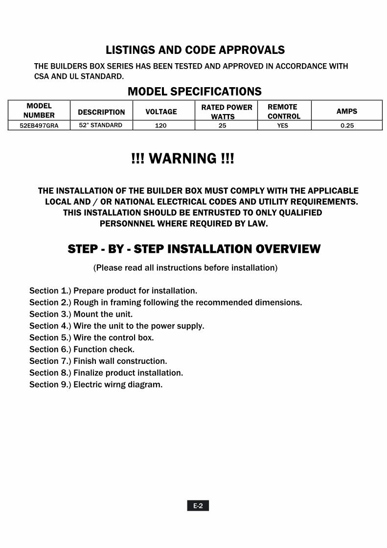
LISTINGS AND CODE APPROVALSTHE BUILDERS BOX SERIES HAS BEEN TESTED AND APPROVED IN ACCORDANCE WITH CSA AND UL STANDARD.
MODEL SPECIFICATIONSMODEL
NUMBER DESCRIPTION VOLTAGE AMPS
120 25 YES 0.2552EB497GRA
!!! WARNING !!!
STEP - BY - STEP INSTALLATION OVERVIEW(Please read all instructions before installation)
52” STANDARD
RATED POWER WATTS
REMOTE CONTROL
THE INSTALLATION OF THE BUILDER BOX MUST COMPLY WITH THE APPLICABLE LOCAL AND / OR NATIONAL ELECTRICAL CODES AND UTILITY REQUIREMENTS. THIS INSTALLATION SHOULD BE ENTRUSTED TO ONLY QUALIFIED PERSONNNEL WHERE REQUIRED BY LAW.
Section 1.) Prepare product for installation.Section 2.) Rough in framing following the recommended dimensions.Section 3.) Mount the unit. Section 4.) Wire the unit to the power supply.Section 5.) Wire the control box. Section 6.) Function check.Section 7.) Finish wall construction. Section 8.) Finalize product installation.Section 9.) Electric wirng diagram.
E-2
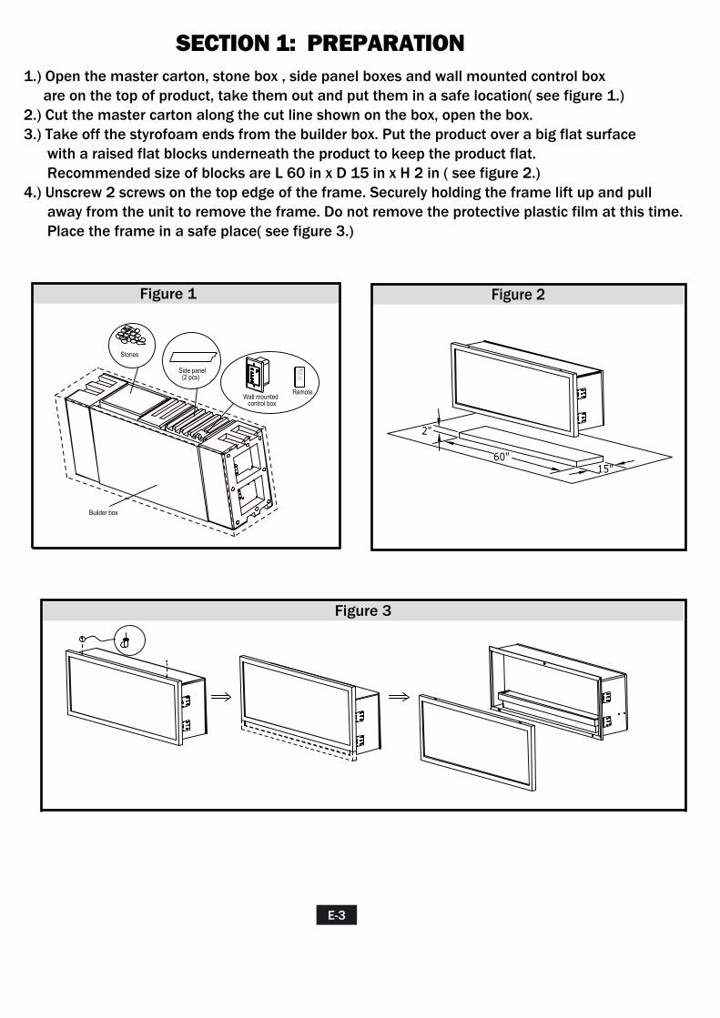
SECTION 1: PREPARATION1.) Open the master carton, stone box , side panel boxes and wall mounted control box are on the top of product, take them out and put them in a safe location( see figure 1.)2.) Cut the master carton along the cut line shown on the box, open the box.3.) Take off the styrofoam ends from the builder box. Put the product over a big flat surface with a raised flat blocks underneath the product to keep the product flat. Recommended size of blocks are L 60 in x D 15 in x H 2 in ( see figure 2.)4.) Unscrew 2 screws on the top edge of the frame. Securely holding the frame lift up and pull away from the unit to remove the frame. Do not remove the protective plastic film at this time. Place the frame in a safe place( see figure 3.)
E-3
60"15"
2"
Figure 2
Side panel (2 pcs)
Wall mounted control box
AUTO
UPLIGHT
DOWNLIGHT
FLAME
Remote
Stones
Builder box
Figure 1
Figure 3
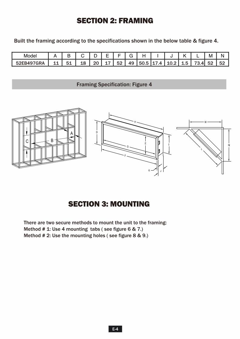
Section 1: Framing
Model A B C D E F G H I J K L M N
52EB497GRA 11 51 18 20 17 52 49 50.5 17.4 10.2 1.5 73.4 52 52
Framing Specification: Figure 4
SECTION 2: FRAMING
Built the framing according to the specifications shown in the below table & figure 4.
SECTION 3: MOUNTING
There are two secure methods to mount the unit to the framing:Method # 1: Use 4 mounting tabs ( see figure 6 & 7.)Method # 2: Use the mounting holes ( see figure 8 & 9.)
E-4
A
C B
MOUNTING TABS
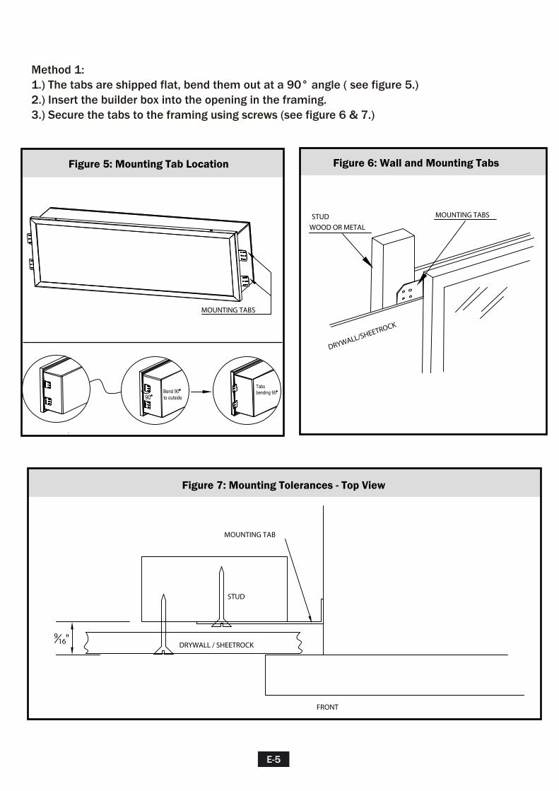
Method 1: 1.) The tabs are shipped flat, bend them out at a 90° angle ( see figure 5.)2.) Insert the builder box into the opening in the framing.3.) Secure the tabs to the framing using screws (see figure 6 & 7.)
E-5
90Bend 90to outside
Tabsbending 90
Figure 5: Mounting Tab Location Figure 6: Wall and Mounting Tabs
Figure 7: Mounting Tolerances - Top View
STUD
WOOD OR METAL
MOUNTING TABS
DRYWALL/SHEETROCK
DRYWALL / SHEETROCK
STUD
FRONT
MOUNTING TAB
916"
E-6
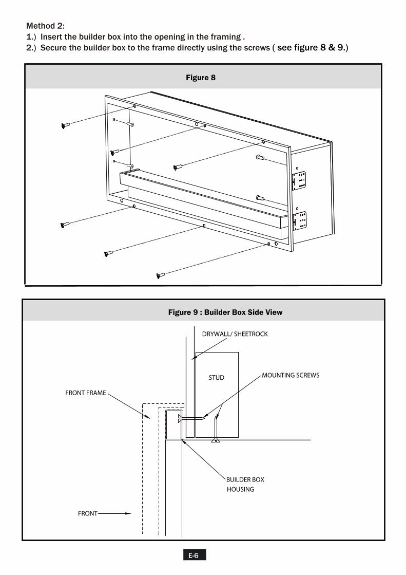
Method 2:1.) Insert the builder box into the opening in the framing .2.) Secure the builder box to the frame directly using the screws ( see figure 8 & 9.)
Figure 8
Figure 9 : Builder Box Side View
FRONT
DRYWALL/ SHEETROCK
MOUNTING SCREWS
FRONT FRAME
BUILDER BOX
HOUSING
STUD
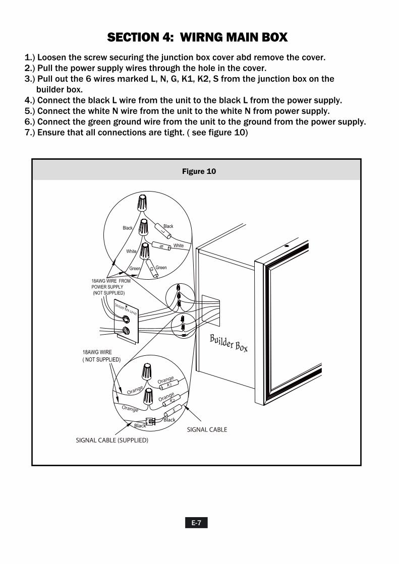
SECTION 4: WIRNG MAIN BOX1.) Loosen the screw securing the junction box cover abd remove the cover.2.) Pull the power supply wires through the hole in the cover.3.) Pull out the 6 wires marked L, N, G, K1, K2, S from the junction box on the builder box. 4.) Connect the black L wire from the unit to the black L from the power supply.5.) Connect the white N wire from the unit to the white N from power supply.6.) Connect the green ground wire from the unit to the ground from the power supply.7.) Ensure that all connections are tight. ( see figure 10)
E-7
Figure 10
18AWG WIRE ( NOT SUPPLIED)
SIGNAL CABLE (SUPPLIED)
SIGNAL CABLE
Juction box cover
Builder Box
LN
G
Black
White
Green
Black
Green
White
18AWG WIRE FROM POWER SUPPLY (NOT SUPPLIED)
Orange
OrangeOrange
Orange
BlackBlack
S
K1
K2

SECTION 5: WIRNG CONTROL BOX1.) Mount one standard single gang junction box in the wall.2.) Prepare 2 orange 18AWG wires, pull one end through the hole on the cover of junction box.3.) Connect one of orange wires to K1 from the unit.4.) Connect another orange wires to K2 from the unit.5.) Find the signal wire which was provided with product. Pull the end through the hole on the cover of junction box.6.) Plug the wire marked S into the unit.7.) Insert all wiring black into the junction box on the unit and secure with a wire tie.8.) Pull the other ends of 2 orange 18AWG wires and signal wire through the hole on wall outlet.9.) Connect one of the orange wires to C1 from the control box.10.) Connect another orange wire to C2 from the control box.11.) Plug the signal wire into the control box.12.) Secure the control box to wall outlet. 13.) Ensure that all connections are tight. ( see figure 11)
E-8
Figure 11
Control
Box Wall outlet
Juction box cover
Builder box
K1K2
S
Black
EXTENSION SIGNAL CABLE (SUPPLIED)
SIGNAL CABLE
C1C2
Orange
Black
Black
18AWG WIRE (NOT SUPPLIED)
Black
Orange
Orange
Orange
Orange
Orange
Orange
Orange
S
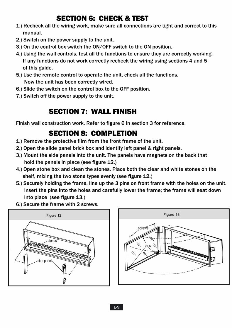
SECTION 6: CHECK & TEST1.) Recheck all the wiring work, make sure all connections are tight and correct to this manual.2.) Switch on the power supply to the unit.3.) On the control box switch the ON/OFF switch to the ON position.4.) Using the wall controls, test all the functions to ensure they are correctly working. If any functions do not work correctly recheck the wiring using sections 4 and 5 of this guide.5.) Use the remote control to operate the unit, check all the functions. Now the unit has been correctly wired.6.) Slide the switch on the control box to the OFF position.7.) Switch off the power supply to the unit.
SECTION 7: WALL FINISHFinish wall construction work. Refer to figure 6 in section 3 for reference.
SECTION 8: COMPLETION1.) Remove the protective film from the front frame of the unit.2.) Open the slide panel brick box and identify left panel & right panels.3.) Mount the side panels into the unit. The panels have magnets on the back that hold the panels in place (see figure 12.) 4.) Open stone box and clean the stones. Place both the clear and white stones on the shelf, mixing the two stone types evenly (see figure 12.) 5.) Securely holding the frame, line up the 3 pins on front frame with the holes on the unit. Insert the pins into the holes and carefully lower the frame; the frame will seat down into place (see figure 13.) 6.) Secure the frame with 2 screws.
E-9
Figure 12
pins
screws
side panel
stones
Figure 13

BUILDER BOX WIRING DIAGRAM
SECTION 9: WIRING SCHEMATIC
E-10
L N
GN
D
M
Tran
sfor
mer
Spi
nner
Mot
or
Wal
l Con
trol B
ox
Mai
n C
ontro
l PC
B
Dow
n Li
ght P
CB
Rem
ote
Rec
eive
r
Flam
e P
CB
Und
er L
ight
PC
B
K1K2
C1
C2
Junc
tion
Box
Jack
S
Gre
en
Whi
te
Bla
ck
Ora
nge
Ora
nge
Whi
teP
urpl
e
Whi
teB
lack
Red
Pur
ple
Red
S
FLA
ME
LE
D
KE
Y
RE
MO
TE
DO
WN
LE
DU
P L
ED
MO
TOR
PO
WE
R
BUILDER BOX ÉLECTRIQUE
NUMÉRO DE MODÈLES : 52EB497GRA
F-1
RENSEIGNEMENTS SUR LA SÉCURITÉVEUILLEZ LIRE CE GUIDE AVANT D’INSTALLER L’APPAREIL
AVERTISSEMENT
Nous vous remercions et vous félicitons d’avoir acheté un foyer Classic Flame.Veuillez lire les instructions d’installation avant d’installer et de faire fonctionner cet appareil.
IMPORTANT: Veuillez lire attentivement toutes les instructions et tous les avertissements avant de commencer l’installation de l’appareil. Ne pas se conformer à ces instructions pourrait entraîner un choc électrique, un risque d’incendie et/ou de blessure, en plus d’annuler la garantie.
Pour le service à la clientèle
NE PAS SUIVRE LES RENSEIGNEMENTS INDIQUÉS DANS CE GUIDE POURRAITENTRAÎNER UN CHOC ÉLECTRIQUE, UN INCENDIE, DES BLESSURES OU LE DÉCÈS.
NE PAS CONSERVER OU UTILISER D’ESSENCE OU TOUT AUTRE LIQUIDE OU SOURCE DE VAPEURS INFLAMMABLES PRÈS DE CET APPAREIL OU DE TOUT AUTRE APPAREIL DU MÊME TYPE.
Twin-Star International, Inc. Delray Beach, FL 33483 U.S.A. Fabriqué en Chine Imprimé en Chine
GUIDE D’INSTALLATION
Courriel: [email protected] en anglais, composez le : 866-661-1218 en français, composez le : 866-374-9203 en espagnol, composez le : 866-661-1218
LISTES ET HOMOLOGATIONS
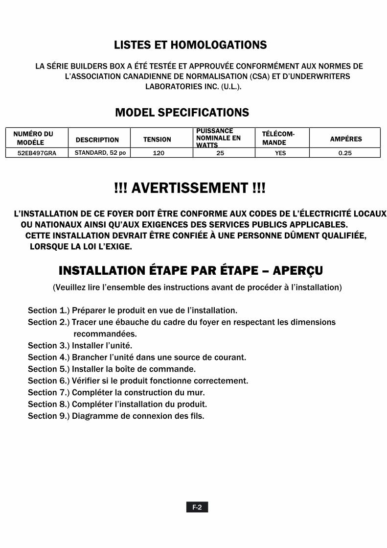
LA SÉRIE BUILDERS BOX A ÉTÉ TESTÉE ET APPROUVÉE CONFORMÉMENT AUX NORMES DE L’ASSOCIATION CANADIENNE DE NORMALISATION (CSA) ET D’UNDERWRITERS LABORATORIES INC. (U.L.).
MODEL SPECIFICATIONS
NUMÉRO DU MODÉLE DESCRIPTION TENSION AMPÉRES
120 25 YES 0.2552EB497GRA
!!! AVERTISSEMENT !!!
INSTALLATION ÉTAPE PAR ÉTAPE – APERÇU(Veuillez lire l’ensemble des instructions avant de procéder à l’installation)
STANDARD, 52 po
PUISSANCE NOMINALE EN WATTS
TÉLÉCOM-MANDE
L’INSTALLATION DE CE FOYER DOIT ÊTRE CONFORME AUX CODES DE L’ÉLECTRICITÉ LOCAUX OU NATIONAUX AINSI QU’AUX EXIGENCES DES SERVICES PUBLICS APPLICABLES. CETTE INSTALLATION DEVRAIT ÊTRE CONFIÉE À UNE PERSONNE DÛMENT QUALIFIÉE, LORSQUE LA LOI L’EXIGE.
Section 1.) Préparer le produit en vue de l’installation.Section 2.) Tracer une ébauche du cadre du foyer en respectant les dimensions recommandées.Section 3.) Installer l’unité.Section 4.) Brancher l’unité dans une source de courant.Section 5.) Installer la boîte de commande.Section 6.) Vérifier si le produit fonctionne correctement.Section 7.) Compléter la construction du mur.Section 8.) Compléter l’installation du produit.Section 9.) Diagramme de connexion des fils.
F-2
LISTES ET HOMOLOGATIONS
LA SÉRIE BUILDERS BOX A ÉTÉ TESTÉE ET APPROUVÉE CONFORMÉMENT AUX NORMES DE L’ASSOCIATION CANADIENNE DE NORMALISATION (CSA) ET D’UNDERWRITERS LABORATORIES INC. (U.L.).
MODEL SPECIFICATIONS
NUMÉRO DU MODÉLE DESCRIPTION TENSION AMPÉRES
120 25 YES 0.2552EB497GRA
!!! AVERTISSEMENT !!!
INSTALLATION ÉTAPE PAR ÉTAPE – APERÇU(Veuillez lire l’ensemble des instructions avant de procéder à l’installation)
STANDARD, 52 po
PUISSANCE NOMINALE EN WATTS
TÉLÉCOM-MANDE
L’INSTALLATION DE CE FOYER DOIT ÊTRE CONFORME AUX CODES DE L’ÉLECTRICITÉ LOCAUX OU NATIONAUX AINSI QU’AUX EXIGENCES DES SERVICES PUBLICS APPLICABLES. CETTE INSTALLATION DEVRAIT ÊTRE CONFIÉE À UNE PERSONNE DÛMENT QUALIFIÉE, LORSQUE LA LOI L’EXIGE.
Section 1.) Préparer le produit en vue de l’installation.Section 2.) Tracer une ébauche du cadre du foyer en respectant les dimensions recommandées.Section 3.) Installer l’unité.Section 4.) Brancher l’unité dans une source de courant.Section 5.) Installer la boîte de commande.Section 6.) Vérifier si le produit fonctionne correctement.Section 7.) Compléter la construction du mur.Section 8.) Compléter l’installation du produit.Section 9.) Diagramme de connexion des fils.
F-2
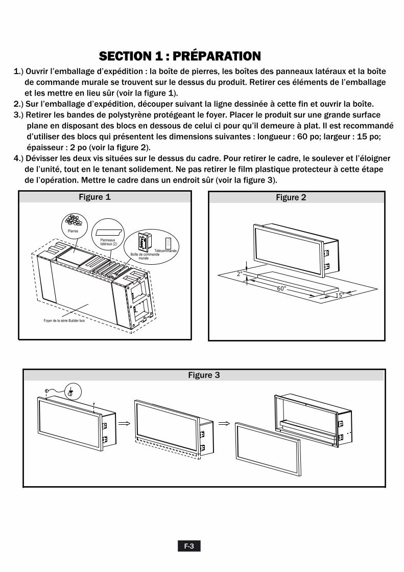
SECTION 1 : PRÉPARATION1.) Ouvrir l’emballage d’expédition : la boîte de pierres, les boîtes des panneaux latéraux et la boîte de commande murale se trouvent sur le dessus du produit. Retirer ces éléments de l’emballage et les mettre en lieu sûr (voir la figure 1).2.) Sur l’emballage d’expédition, découper suivant la ligne dessinée à cette fin et ouvrir la boîte.3.) Retirer les bandes de polystyrène protégeant le foyer. Placer le produit sur une grande surface plane en disposant des blocs en dessous de celui ci pour qu’il demeure à plat. Il est recommandé d’utiliser des blocs qui présentent les dimensions suivantes : longueur : 60 po; largeur : 15 po; épaisseur : 2 po (voir la figure 2).4.) Dévisser les deux vis situées sur le dessus du cadre. Pour retirer le cadre, le soulever et l’éloigner de l’unité, tout en le tenant solidement. Ne pas retirer le film plastique protecteur à cette étape de l’opération. Mettre le cadre dans un endroit sûr (voir la figure 3).
F-3
60"15"
2"
Figure 2
Panneaux latéraux (2)
Boîte de commande murale
AUTO
UPLIGHT
DOWNLIGHT
FLAME
Télécommande
Pierres
Foyer de la série Builder box
Figure 1
Figure 3
Section 1: Framing
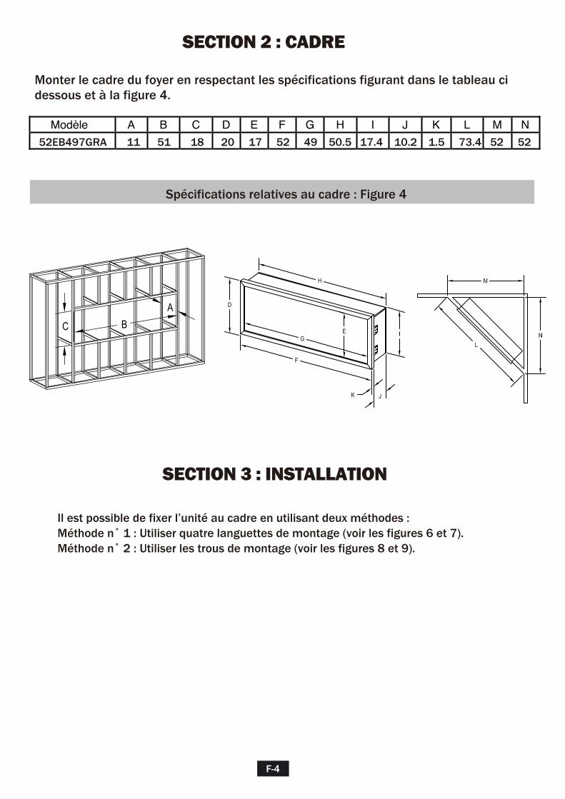
Modèle A B C D E F G H I J K L M N
52EB497GRA 11 51 18 20 17 52 49 50.5 17.4 10.2 1.5 73.4 52 52
Spécifications relatives au cadre : Figure 4
SECTION 2 : CADRE
Monter le cadre du foyer en respectant les spécifications figurant dans le tableau ci dessous et à la figure 4.
SECTION 3 : INSTALLATION
Il est possible de fixer l’unité au cadre en utilisant deux méthodes :Méthode n˚ 1 : Utiliser quatre languettes de montage (voir les figures 6 et 7).Méthode n˚ 2 : Utiliser les trous de montage (voir les figures 8 et 9).
F-4
A
C B

LANGUETTES DE MONTAGE
Méthode n˚ 1 :1.) Les languettes fournies sont planes; les plier à un angle de 90 ° (voir la figure 5).2.) Insérer « l’ensemble foyer » dans l’ouverture du cadre.3.) Fixer les languettes sur le cadre à l’aide de vis (voir les figures 6 et 7).
F-5
90Languettes pliées à 90 ° vers l’extérieur
Languettes pliées à 90 °
Figure 5 : Emplacement de la languette de montage Figure 6 : Languettes murales et de montage
Figure 7 : Tolérances requises pour le montage – vue du dessus
MONTANTBOIS OU MÉTAL
LANGUETTES DE MONTAGES
CLOISON SÈCHE/PANNEAU DE PLÂTRE
CLOISON SÈCHE/PANNEAU DE PLÂTRE
MONTANT
AVANT
ANGUETTE DE MONTAGE
916"
F-6
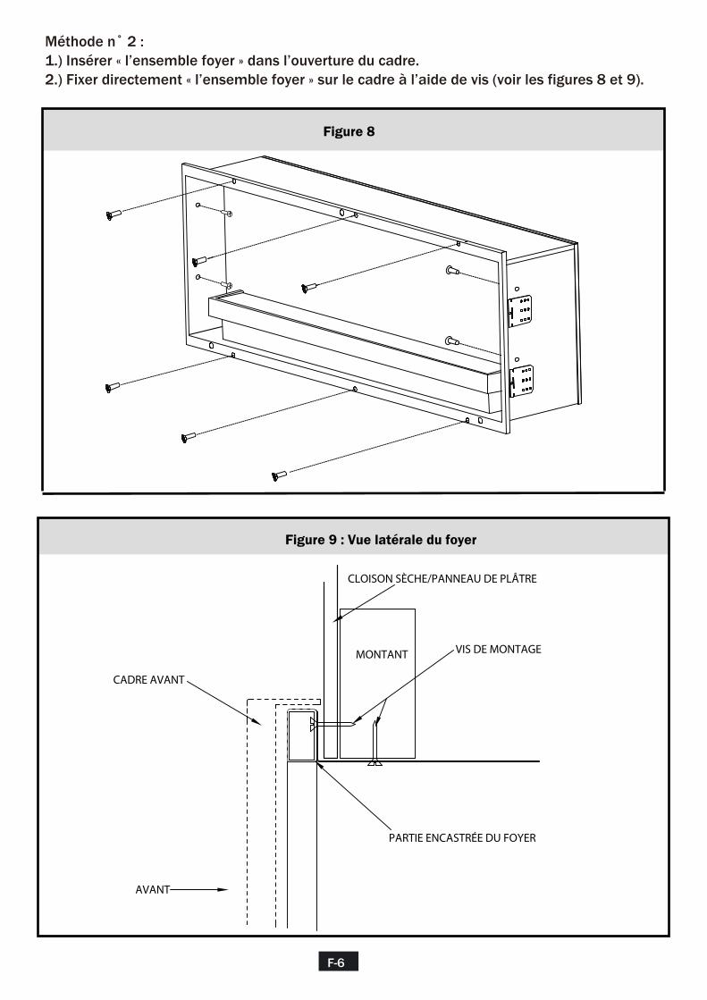
Méthode n˚ 2 :1.) Insérer « l’ensemble foyer » dans l’ouverture du cadre.2.) Fixer directement « l’ensemble foyer » sur le cadre à l’aide de vis (voir les figures 8 et 9).
Figure 8
Figure 9 : Vue latérale du foyer
AVANT
CLOISON SÈCHE/PANNEAU DE PLÂTRE
VIS DE MONTAGE
CADRE AVANT
PARTIE ENCASTRÉE DU FOYER
MONTANT
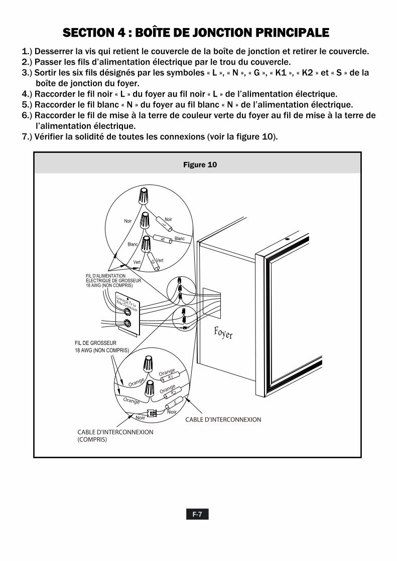
SECTION 4 : BOÎTE DE JONCTION PRINCIPALE1.) Desserrer la vis qui retient le couvercle de la boîte de jonction et retirer le couvercle.2.) Passer les fils d’alimentation électrique par le trou du couvercle.3.) Sortir les six fils désignés par les symboles « L », « N », « G », « K1 », « K2 » et « S » de la boîte de jonction du foyer. 4.) Raccorder le fil noir « L » du foyer au fil noir « L » de l’alimentation électrique.5.) Raccorder le fil blanc « N » du foyer au fil blanc « N » de l’alimentation électrique.6.) Raccorder le fil de mise à la terre de couleur verte du foyer au fil de mise à la terre de l’alimentation électrique.7.) Vérifier la solidité de toutes les connexions (voir la figure 10).
F-7
Figure 10
FIL DE GROSSEUR 18 AWG (NON COMPRIS)
CABLE D’INTERCONNEXION (COMPRIS)
CABLE D’INTERCONNEXION
Couvercle De La Boîte De Jonction
Foyer
LN
G
Noir
Blanc
Vert
Noir
Vert
Blanc
FIL D’ALIMENTATION ÉLECTRIQUE DE GROSSEUR18 AWG (NON COMPRIS)
Orange
OrangeOrange
Orange
Noir Noir
S
K1
K2
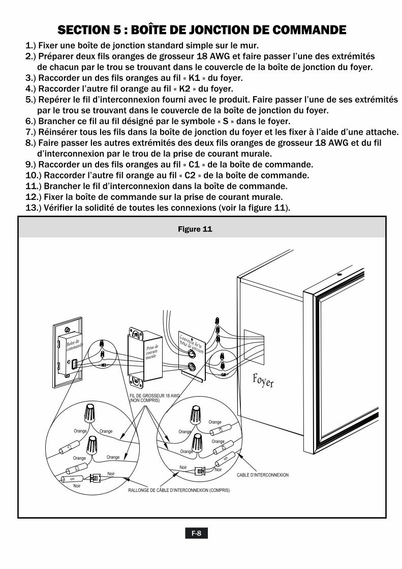
SECTION 5 : BOÎTE DE JONCTION DE COMMANDE1.) Fixer une boîte de jonction standard simple sur le mur.2.) Préparer deux fils oranges de grosseur 18 AWG et faire passer l’une des extrémités de chacun par le trou se trouvant dans le couvercle de la boîte de jonction du foyer.3.) Raccorder un des fils oranges au fil « K1 » du foyer.4.) Raccorder l’autre fil orange au fil « K2 » du foyer.5.) Repérer le fil d’interconnexion fourni avec le produit. Faire passer l’une de ses extrémités par le trou se trouvant dans le couvercle de la boîte de jonction du foyer.6.) Brancher ce fil au fil désigné par le symbole « S » dans le foyer.7.) Réinsérer tous les fils dans la boîte de jonction du foyer et les fixer à l’aide d’une attache.8.) Faire passer les autres extrémités des deux fils oranges de grosseur 18 AWG et du fil d’interconnexion par le trou de la prise de courant murale.9.) Raccorder un des fils oranges au fil « C1 » de la boîte de commande.10.) Raccorder l’autre fil orange au fil « C2 » de la boîte de commande.11.) Brancher le fil d’interconnexion dans la boîte de commande.12.) Fixer la boîte de commande sur la prise de courant murale.13.) Vérifier la solidité de toutes les connexions (voir la figure 11).
F-8
Figure 11
Boîte de
commandePrise de courant murale
Couvercle de la boîte de jonction
Foyer
K1K2
S
Noir
RALLONGE DE CÂBLE D’INTERCONNEXION (COMPRIS)
CABLE D’INTERCONNEXION
C1C2
Orange
Noir
Noir
FIL DE GROSSEUR 18 AWG (NON COMPRIS)
Noir
Orange
Orange
Orange
Orange
Orange
Orange
Orange
S
SECTION 6 : VÉRIFICATION ET MISE À L’ESSAI1.) Vérifier de nouveau l’ensemble des connexions en s’assurant qu’elles sont solides et conformes aux directives décrites dans le présent manuel.2.) Mettre l’unité sous tension.3.) Sur la boîte de commande, régler l’interrupteur ON/OFF (MARCHE/ARRÊT) à la position « ON ».4.) En utilisant les boutons de commande muraux, mettre à l’essai l’ensemble des fonctionnalités afin de s’assurer que celles-ci permettent d’obtenir le résultat prévu. Si l’une ou l’autre des fonctionnalités présente une défaillance, vérifier de nouveau les connexions en consultant les sections 4 et 5 du présent manuel.5.) Faire fonctionner l’unité à l’aide de la télécommande et vérifier l’ensemble des fonctionnalités. L’installation électrique du foyer a été effectuée correctement.6.) Régler l’interrupteur de la boîte de commande à la position « OFF ».7.) Mettre l’unité hors tension.
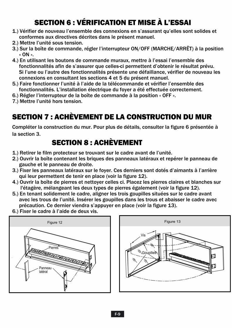
SECTION 7 : ACHÈVEMENT DE LA CONSTRUCTION DU MURCompléter la construction du mur. Pour plus de détails, consulter la figure 6 présentée à la section 3.
SECTION 8 : ACHÈVEMENT1.) Retirer le film protecteur se trouvant sur le cadre avant de l’unité.2.) Ouvrir la boîte contenant les briques des panneaux latéraux et repérer le panneau de gauche et le panneau de droite.3.) Fixer les panneaux latéraux sur le foyer. Ces derniers sont dotés d’aimants à l’arrière qui leur permettent de tenir en place (voir la figure 12).4.) Ouvrir la boîte de pierres et nettoyer celles ci. Placez les pierres claires et blanches sur l'étagère, mélangeant les deux types de pierres également (voir la figure 12).5.) En tenant solidement le cadre, aligner les trois goupilles situées sur le cadre avant avec les trous de l’unité. Insérer les goupilles dans les trous et abaisser le cadre avec précaution. Ce dernier viendra s’appuyer en place (voir la figure 13).6.) Fixer le cadre à l’aide de deux vis.
F-9
Figure 12
Goupilles
Vis
Panneau latéral
Pierres
Figure 13

SCHÉMA DE CÂBLAGE DU FOYER
SECTION 9 : SCHÉMA DE CÂBLAGE
F-10
L N
GN
D
M
Tran
sfor
mat
eur
Mot
eur d
e l’é
lém
ent r
otat
ifBoî
te d
e co
mm
ande
mur
ale
Car
te d
e ci
rcui
ts im
prim
és d
e la
boî
te
de c
omm
ande
prin
cipa
le
Car
te d
e ci
rcui
ts im
prim
és d
u pr
ojec
teur
de
plaf
ond
Réc
epte
ur é
loig
né
Car
te d
e ci
rcui
ts
impr
imés
de
la
flam
me
Car
te d
e ci
rcui
ts
impr
imés
du
proj
ecte
ur a
u so
l
K1K2
C1
C2
Boî
te d
e jo
nctio
n
Con
nect
eur
fem
elle
S
Ver
t
Bla
nc
Noi
r
Ora
nge
Ora
nge
Bla
ncV
iole
t
Bla
ncN
oir
Rou
ge
Vio
let
Rou
ge
S
DÉ
L «
FLA
ME
»
CLE
F
TÉLÉ
CO
MM
AN
DE
DÉ
L «
DO
WN
»D
ÉL
« U
P »
MO
TEU
R
ALI
ME
NTA
TIO
N
BUILDER BOX ELÉCTRICA
NÚMERO DE MODELO:
52EB497GRA
GUÍA DE INSTALACIÓN
S-1
INFORMACIÓN SOBRE SEGURIDAD PARA EL CONSUMIDOR LEA ESTE MANUAL ANTES DE INSTALAR EL APARATO
ADVERTENCIA
Gracias y felicitaciones por su adquisición de una chimenea Classic Flame. Lea las instrucciones de instalación antes de instalar y operar este aparato. IMPORTANTE: Lea todas las instrucciones y advertencias con detenimiento antes de comenzar la instalación. Si no se siguen las instrucciones, podría provocarse riesgo rde descarga eléctrica, incendio o lesiones y, además, la garantía perdería validez.
Para el servicio a la clientela: Correo eléctrico: [email protected] En inglés, llame a: 866-661-1218 En francés, llame a: 866-374-9203 En español, llame a: 866-611-1218
Twin-Star International, Inc. Delray Beach, FL 33483 U.S.A. Made in China Printed in China
EN CASO DE NO SEGUIR LA INFORMACIÓN EN ESTE MANUAL, PODRÍA OCURRIR UNA DESCARGA ELÉCTRICA O INCENDIO Y, COMO CONSECUENCIA, DAÑOS A LA PROPIEDAD, LESIONES PERSONALES O LA PÉRDIDA DE LA VIDA. NO GUARDE NI USE GASOLINA NI OTROS VAPORES Y LÍQUIDOS INFLAMABLES EN LA CERCANÍA DE ESTE APARATO, NI DE CUALQUIER OTRO.
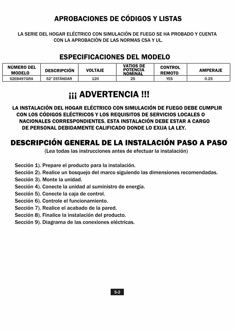
APROBACIONES DE CÓDIGOS Y LISTAS
LA SERIE DEL HOGAR ELÉCTRICO CON SIMULACIÓN DE FUEGO SE HA PROBADO Y CUENTA CON LA APROBACIÓN DE LAS NORMAS CSA Y UL.
ESPECIFICACIONES DEL MODELONÚMERO DEL MODELO DESCRIPCIÓN VOLTAJE AMPERAJE
120 25 YES 0.2552EB497GRA
¡¡¡ ADVERTENCIA !!!
DESCRIPCIÓN GENERAL DE LA INSTALACIÓN PASO A PASO(Lea todas las instrucciones antes de efectuar la instalación)
52” ESTÁNDAR
VATIOS DE POTENCIA NOMINAL
CONTROL REMOTO
LA INSTALACIÓN DEL HOGAR ELÉCTRICO CON SIMULACIÓN DE FUEGO DEBE CUMPLIR CON LOS CÓDIGOS ELÉCTRICOS Y LOS REQUISITOS DE SERVICIOS LOCALES O NACIONALES CORRESPONDIENTES. ESTA INSTALACIÓN DEBE ESTAR A CARGO DE PERSONAL DEBIDAMENTE CALIFICADO DONDE LO EXIJA LA LEY.
Sección 1). Prepare el producto para la instalación.Sección 2). Realice un bosquejo del marco siguiendo las dimensiones recomendadas.Sección 3). Monte la unidad. Sección 4). Conecte la unidad al suministro de energía.Sección 5). Conecte la caja de control. Sección 6). Controle el funcionamiento.Sección 7). Realice el acabado de la pared. Sección 8). Finalice la instalación del producto.Sección 9). Diagrama de las conexiones eléctricas.
S-2
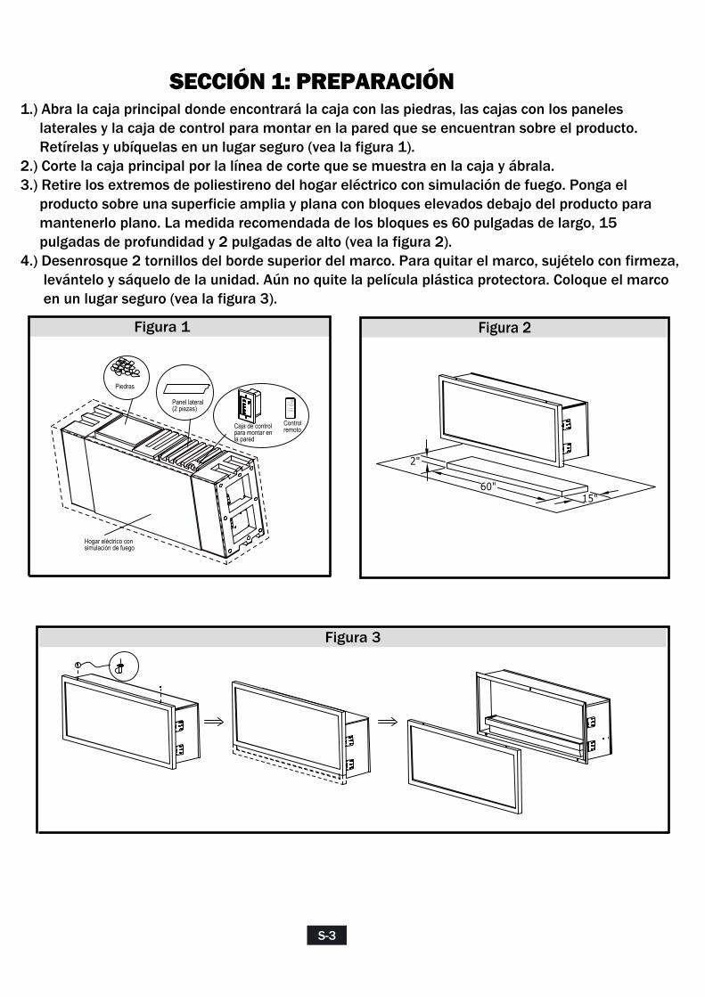
SECCIÓN 1: PREPARACIÓN1.) Abra la caja principal donde encontrará la caja con las piedras, las cajas con los paneles laterales y la caja de control para montar en la pared que se encuentran sobre el producto. Retírelas y ubíquelas en un lugar seguro (vea la figura 1).2.) Corte la caja principal por la línea de corte que se muestra en la caja y ábrala.3.) Retire los extremos de poliestireno del hogar eléctrico con simulación de fuego. Ponga el producto sobre una superficie amplia y plana con bloques elevados debajo del producto para mantenerlo plano. La medida recomendada de los bloques es 60 pulgadas de largo, 15 pulgadas de profundidad y 2 pulgadas de alto (vea la figura 2).4.) Desenrosque 2 tornillos del borde superior del marco. Para quitar el marco, sujételo con firmeza, levántelo y sáquelo de la unidad. Aún no quite la película plástica protectora. Coloque el marco en un lugar seguro (vea la figura 3).
S-3
60"15"
2"
Figura 2
Panel lateral (2 piezas)
Caja de control para montar en la pared
AUTO
UPLIGHT
DOWNLIGHT
FLAME
Controlremoto
Piedras
Hogar eléctrico con simulación de fuego
Figura 1
Figura 3

Section 1: Framing
Modelo A B C D E F G H I J K L M N
52EB497GRA 11 51 18 20 17 52 49 50.5 17.4 10.2 1.5 73.4 52 52
Especificaciones del marco: Figura 4
SECCIÓN 2: MARCO
Arme el marco de acuerdo con las especificaciones que se muestran en la siguiente tabla y en la figura 4.
SECCIÓN 3: MONTAJE
Existen dos métodos seguros para montar la unidad al marco:Método n.º 1: Utilice 4 lengüetas de montaje (vea las figuras 6 y 7).Método n.º 2: Utilice los orificios de montaje (vea las figuras 8 y 9).
S-4
A
C B
LENGÜETAS DE MONTAJE
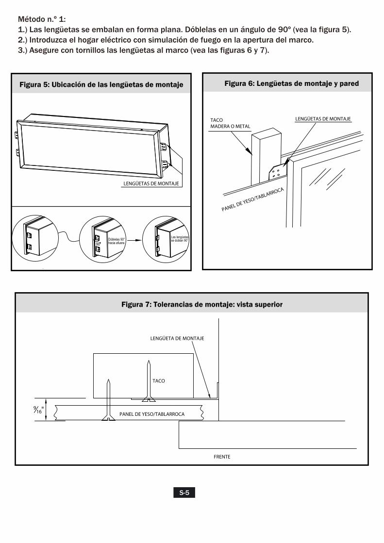
Método n.º 1: 1.) Las lengüetas se embalan en forma plana. Dóblelas en un ángulo de 90º (vea la figura 5).2.) Introduzca el hogar eléctrico con simulación de fuego en la apertura del marco.3.) Asegure con tornillos las lengüetas al marco (vea las figuras 6 y 7).
S-5
90Dóblelas 90° hacia afuera
Las lengüetas se doblan 90°
Figura 5: Ubicación de las lengüetas de montaje Figura 6: Lengüetas de montaje y pared
Figura 7: Tolerancias de montaje: vista superior
TACOMADERA O METAL
LENGÜETAS DE MONTAJE
PANEL DE YESO/TABLARROCA
PANEL DE YESO/TABLARROCA
TACO
FRENTE
LENGÜETA DE MONTAJE
916"
S-6
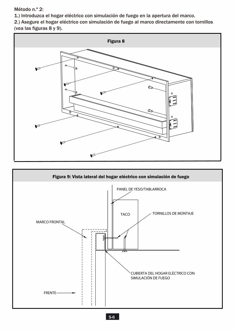
Método n.º 2:1.) Introduzca el hogar eléctrico con simulación de fuego en la apertura del marco.2.) Asegure el hogar eléctrico con simulación de fuego al marco directamente con tornillos (vea las figuras 8 y 9).
Figura 8
Figura 9: Vista lateral del hogar eléctrico con simulación de fuego
FRENTE
PANEL DE YESO/TABLARROCA
TORNILLOS DE MONTAJE
MARCO FRONTAL
CUBIERTA DEL HOGAR ELÉCTRICO CON SIMULACIÓN DE FUEGO
TACO
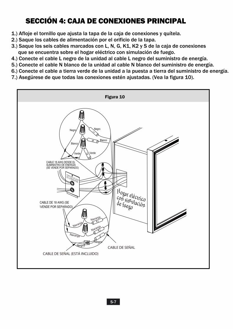
SECCIÓN 4: CAJA DE CONEXIONES PRINCIPAL1.) Afloje el tornillo que ajusta la tapa de la caja de conexiones y quítela.2.) Saque los cables de alimentación por el orificio de la tapa.3.) Saque los seis cables marcados con L, N, G, K1, K2 y S de la caja de conexiones que se encuentra sobre el hogar eléctrico con simulación de fuego. 4.) Conecte el cable L negro de la unidad al cable L negro del suministro de energía.5.) Conecte el cable N blanco de la unidad al cable N blanco del suministro de energía.6.) Conecte el cable a tierra verde de la unidad a la puesta a tierra del suministro de energía.7.) Asegúrese de que todas las conexiones estén ajustadas. (Vea la figura 10).
S-7
Figura 10
CABLE DE 18 AWG (SE \VENDE POR SEPARADO)
CABLE DE SEÑAL (ESTÁ INCLUIDO)
CABLE DE SEÑAL
TAPA DE LA CAJA DE CONEXIONES
Hogar eléctrico con simulación de fuego
LN
G
Negro
Blanco
Verde
Negro
Verde
Blanco
CABLE 18 AWG DESDE EL SUMINISTRO DE ENERGÍA (SE VENDE POR SEPARADO)
Naranja
NaranjaNaranja
Naranja
NegroNegro
S
K1
K2

SECCIÓN 5: CAJA DE CONTROL DE LAS CONEXIONES1.) Monte una sola caja de conexiones en la pared.2.) Prepare 2 cables de 18 AWG naranjas, saque uno a través del orificio de la tapa de la caja de conexiones.3.) Conecte uno de los cables naranjas al cable K1 de la unidad.4.) Conecte otro cable naranja al cable K2 de la unidad.5.) Encuentre el cable de señal que viene con el producto. Saque el extremo a través del orificio de la tapa de la caja de conexiones.6.) Conecte el cable marcado con una S en la unidad.7.) Introduzca todos los cables negros en la caja de conexiones de la unidad y asegúrelos con un precinto.8.) Saque los otros extremos de dos cables de 18 AWG naranjas y del cable de señal a través del orificio en el tomacorriente de pared.9.) Conecte uno de los cables naranjas al cable C1 desde la caja de control.10.) Conecte otro cable naranja al cable C2 desde la caja de control.11.) Enchufe el cable de señal en la caja de control.12.) Asegure la caja de control al tomacorriente de pared. 13.) Asegúrese de que todas las conexiones estén ajustadas. (Vea la figura 11).
S-8
Figura 11
Caja de
control Tomacorri
-ente de pared
Tapa de la caja de conexiones
Hogar eléctrico con simulación de fuego
K1K2
S
Negro
CABLE PROLONGADOR DE SEÑAL (ESTÁ INCLUIDO)
CABLE DE SEÑAL
C1C2
Naranja
Negro
Negro
CABLE DE 18 AWG (SE VENDE POR SEPARADO)
Negro
Naranja
Naranja
Naranja
Naranja
Naranja
Naranja
Naranja
S

SECCIÓN 6: VERIFICACIÓN Y PRUEBA1.) Vuelva a verificar que todo el cableado funcione correctamente, y asegúrese de que todas las conexiones estén firmes y concuerden con el manual.2.) Encienda el suministro de energía de la unidad.3.) En la caja de control, encienda el interruptor de ON/OFF (encendido/apagado).4.) Use los controles de pared para probar todas las funciones, a fin de asegurarse de que funcionen correctamente. Si alguna función no funciona correctamente, vuelva a verificar el cableado siguiendo las secciones 4 y 5 de esta guía.5.) Utilice el control remoto para operar esta unidad y verifique todas las funciones. La unidad está conectada correctamente.6.) Deslice el interruptor de la caja de control a la posición OFF (apagado).7.) Desconecte el suministro de energía que alimenta la unidad.
SECCIÓN 7: ACABADO DE LA PAREDRealice el acabado de la pared. Tenga en cuenta la figura 6 de la sección 3 como referencia.
SECCIÓN 8: TERMINACIÓN1.) Retire la película protectora del marco frontal de la unidad.2.) Abra la caja de los paneles deslizables de ladrillo, e identifique el panel izquierdo y el panel derecho.3.) Monte los paneles laterales en la unidad. Los paneles tienen imanes en la parte posterior que mantienen los paneles en su lugar (vea la figura 12). 4.) Abra la caja de las piedras y límpielas. Coloque las piedras claras y blancas en la repisa, mezclando los dos tipos de piedra uniformemente (vea la figura 12). 5.) Sostenga el marco con firmeza y alinee las tres clavijas del marco frontal con los orificios de la unidad. Introduzca las clavijas en los orificios y baje cuidadosamente el marco; el marco se asentará en su lugar (vea la figura 13). 6.) Asegure el marco con dos tornillos.
S-9
Figura 12
Clavijas
Tornillos
Panel lateral
Piedras
Figura 13
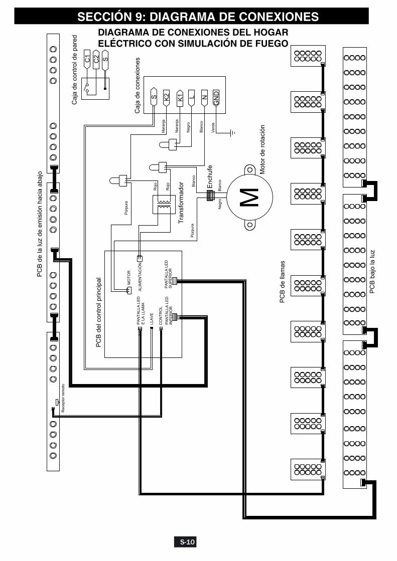
DIAGRAMA DE CONEXIONES DEL HOGAR ELÉCTRICO CON SIMULACIÓN DE FUEGO
SECCIÓN 9: DIAGRAMA DE CONEXIONES
S-10
L N
GN
D
M
Tran
sfor
mad
or
Mot
or d
e ro
taci
ón
Caj
a de
con
trol d
e pa
red
PC
B d
el c
ontro
l prin
cipa
l PC
B d
e la
luz
de e
mis
ión
haci
a ab
ajo
Rec
epto
r rem
oto
PC
B d
e lla
mas
PC
B b
ajo
la lu
z
K1K2
C1
C2
Caj
a de
con
exio
nes
Enc
hufe
S
Ver
de
Bla
nco
Neg
ro
Nar
anja
Nar
anja
Bla
nco
Púr
pura
Bla
nco
Neg
ro
Roj
o
Púr
pura
Roj
o
S
PA
NTA
LLA
LE
D
E L
A L
LAM
A
LLA
VE
CO
NTR
OL
PA
NTA
LLA
LE
D
INFE
RIO
RP
AN
TALL
A L
ED
S
UP
ER
IOR
MO
TOR
ALI
ME
NTA
CIÓ
N
ATTENTIONIF YOU HAVE ANY PROBLEMS OR QUESTIONS, EMAIL OR CALL CUSTOMER SERVICE BEFORE YOU RETURN
THIS PRODUCT TO THE STORE WHERE IT WAS PURCHASED.For Customer Service: email: [email protected] English Call: 866-661-1218in Spanish Call: 866-661-1218in French Call: 866-374-9203
ATENCIÓNSI TIENE ALGÚN PROBLEMA O PREGUNTAS,
ENVÍE UN MENSAJE DE CORREO ELECTRÓNICO O LLAME AL SERVICIO DE ATENCIÓN AL CLIENTE ANTES DE DEVOLVER
ESTE PRODUCTO A LA TIENDA EN LA QUE LO COMPRÓ.Servicio de atención al cliente: Correo electrónico: [email protected]
Línea para llamadas en inglés: 866-661-1218Línea para llamadas en español: 866-661-1218Línea para llamadas en francés: 866-374-9203
STOP STOP
PARE PARE
ATTENTIONSI VOUS AVEZ DES PROBLÈMES OU DES QUESTIONS,
ENVOYEZ UN COURRIEL AU SERVICE À LA CLIENTÈLE OU APPELEZ LE SERVICE À LA CLIENTÈLE AVANT DE RETOURNER
CE PRODUIT OÙ VOUS L’AVEZ ACHETÉ.Pour le service à la clientèle : courriel : [email protected]
pour le service en anglais, composez le 866-661-1218pour le service en espagnol, composez le 866-661-1218pour le service en français, composez le 866-374-9203
ARRÊT ARRÊT
INSTRUCTION MANUAL ENCLOSEDMANUEL D’INSTRUCTION À L’INTÉRIEURMANUAL DE INSTRUCCIONES ADJUNTO
INSTRUCTION MANUAL ENCLOSEDMANUEL D’INSTRUCTION À L’INTÉRIEURMANUAL DE INSTRUCCIONES ADJUNTO
![46112882 drywall[1]](https://static.fdocuments.es/doc/165x107/55673609d8b42a986b8b50f5/46112882-drywall1.jpg)

![Diapos Drywall[1]](https://static.fdocuments.es/doc/165x107/557201a94979599169a20f79/diapos-drywall1.jpg)