Modelación de Vigas Reforzadas a Corte con CFRP...
12
28 / Investigaciones de los alumnos Modelación de Vigas Reforzadas a Corte con CFRP en ATENA 3D Modeling of Reinforced Beams under Shear with CFRP in ATENA 3D 46 / Investigaciones de los alumnos José Luis Jiménez Ulloa 1 , alumno de magíster. Wassim M. Ghannoum 2 , profesor asistente. Hernán Santa María 1 , profesor titular. 1 Departamento de Ingeniería Estructural y Geotécnica, Escuela de Ingeniería, Pontificia Universidad Católica de Chile. 2 Departmento de Ingeniería Civil, Arquitectónica y Ambiental, Escuela de Ingeniería, e University of Texas at Austin. *Autor para correspondencia: [email protected]. José Luis Jiménez Ulloa 1 , master’s student. Wassim M. Ghannoum 2 , assistant professor. Hernán Santa María 1 , full professor. 1 Departament of Structural and Geotechnical Engineering, School of Engineering, Pontificia Universidad Católica de Chile. 2 Department of Civil, Architectural and Environmental Engineering, School of Engineering, e University of Texas at Austin. *Correspondence author: [email protected].
-
Upload
hoangkhanh -
Category
Documents
-
view
215 -
download
0
Transcript of Modelación de Vigas Reforzadas a Corte con CFRP...

28 / Investigaciones de los alumnos
Modelación de Vigas Reforzadas a Corte con CFRP en ATENA 3DModeling of Reinforced Beams under Shear with CFRP in ATENA 3D
46 / Investigaciones de los alumnos
José Luis Jiménez Ulloa1, alumno de magíster.Wassim M. Ghannoum2, profesor asistente.Hernán Santa María1, profesor titular.
1Departamento de Ingeniería Estructural y Geotécnica, Escuela de Ingeniería, Pontificia Universidad Católica de Chile.2Departmento de Ingeniería Civil, Arquitectónica y Ambiental, Escuela de Ingeniería, The University of Texas at Austin.*Autor para correspondencia: [email protected].
José Luis Jiménez Ulloa1, master’s student.Wassim M. Ghannoum2, assistant professor.Hernán Santa María1, full professor.
1Departament of Structural and Geotechnical Engineering, School of Engineering, Pontificia Universidad Católica de Chile.2Department of Civil, Architectural and Environmental Engineering, School of Engineering, The University of Texas at Austin.*Correspondence author: [email protected].
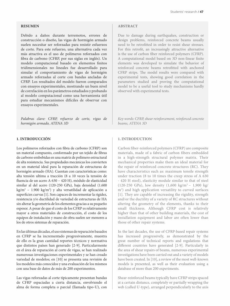
1. INTRODUCCIÓN
Los polímeros reforzados con fibra de carbono (CFRP) son un material compuesto, conformado por un tejido de fibras de carbono embebidas en una matriz de polímero estructural de alta resistencia. Sus propiedades mecánicas los convierten en un material ideal para la reparación de estructuras de hormigón armado (HA). Cuentan con características como: alta tensión ultima a tracción (8 a 10 veces la tensión de fluencia de un acero A 630 – 420 H), módulo de elasticidad similar al del acero (120-250 GPa), baja densidad (1.600 kg/m3 – 1.900 kg/m3) y alta versatilidad de aplicación a superficies curvas [1]. Son capaces de incrementar la rigidez, resistencia y/o ductilidad de variedad de estructuras de HA sin alterar la geometría de los elementos gracias a su pequeño espesor. A pesar de que el costo de los CFRP es relativamente mayor a otros materiales de construcción, el costo de los equipos de instalación y mano de obra suelen ser menores a los de otros sistemas de reparación.
En las últimas décadas, el uso sistemas de reparación basados en CFRP se ha incrementado progresivamente, muestra de ello es la gran cantidad reportes técnicos y normativa que distintos países han generado [2-9]. Particularmente en el área de reparación al corte de vigas, se han realizado numerosas investigaciones experimentales y se han creado variedad de modelos; en [10] se presenta una revisión de los modelos más conocidos y una evaluación de los mismos con una base de datos de más de 200 experimentos.
Las vigas reforzadas al corte típicamente presentan bandas de CFRP espaciadas a cierta distancia, envolviendo el alma de forma completa o parcial (llamada tipo-U), con
ABSTRACT
Due to damage during earthquakes, construction or design problems, reinforced concrete beams usually need to be retrofitted in order to resist shear stresses. For this retrofit, an increasingly attractive alternative is the use of carbon fiber reinforced polymers (CFRP). A computational model based on 3D non-linear finite elements was developed to simulate the behavior of reinforced concrete beams retrofitted with anchored CFRP strips. The model results were compared with experimental tests, showing good correlation in the parameters studied and proving the computational model to be a useful tool to study mechanisms hardly observed with experimental tests.
Key words: CFRP, shear reinforcement, reinforced concrete beams, ATENA 3D
RESUMEN
Debido a daños durante terremotos, errores de construcción o diseño, las vigas de hormigón armado suelen necesitar ser reforzadas para resistir esfuerzos de corte. Para este refuerzo, una alternativa cada vez más atractiva es el uso de polímeros reforzados con fibra de carbono (CFRP, por sus siglas en inglés). Un modelo computacional basado en elementos finitos tridimensionales no lineales fue desarrollado para simular el comportamiento de vigas de hormigón armado reforzadas al corte con bandas ancladas de CFRP. Los resultados del modelo fueron comparados con ensayos experimentales, mostrando un buen nivel de correlación en los parámetros estudiados y probando al modelo computacional como una herramienta útil para estudiar mecanismos difíciles de observar con ensayos experimentales.
Palabras clave: CFRP, refuerzo de corte, vigas de hormigón armado, ATENA 3D
1. INTRODUCTION
Carbon fiber-reinforced polymers (CFRP) are composite materials, made of a fabric of carbon fibers embedded in a high-strength structural polymer matrix. Their mechanical properties make them an ideal material for the repair of reinforced concrete structures (RC). They have characteristics such as: maximum tensile strength under traction (8 to 10 times the creep stress of A 630 - 420 H steel), elasticity module similar to that of steel (120-250 GPa), low density (1,600 kg/m3 – 1,900 kg/m3) and high application versatility to curved surfaces [1]. They are capable of increasing the rigidity, strength and/or the ductility of a variety of RC structures without altering the geometry of the elements, thanks to their small thickness. Although CFRP cost is relatively higher than that of other building materials, the cost of installation equipment and labor are often lower than those of other repair systems.
In the last decades, the use of CFRP-based repair systems has increased progressively, as demonstrated by the great number of technical reports and regulations that different countries have generated [2-9]. Particularly in the area of shear repairs of beams, numerous experimental investigations have been carried out and a variety of models have been created. In [10], a review of the most well-known models is presented, as well as their evaluation using a database of more than 200 experiments.
Shear-reinforced beams typically have CFRP strips spaced at a certain distance, completely or partially wrapping the web (called U-type), arranged perpendicularly to the axis
Students’ research / 47

una disposición perpendicular al eje o inclinadas con cierto ángulo. El esquema de envoltura completa logra aprovechar de forma más eficiente las propiedades del CFRP, aun así, una envoltura tipo U suele ser necesaria debido a impedimentos geométricos de la estructura (e.g. losas de piso, cubiertas de puentes).
Kim et al. [11, 12] estudiaron experimentalmente la contribución de refuerzos de CFRP a la resistencia al corte en vigas tipo T de hormigón armado. El sistema de anclajes de CFRP propuesto en los ensayos experimentales de [11, 12] permite el desarrollo la resistencia máxima de las bandas de CFRP (Figura 1). Estos ensayos fueron realizados en vigas simplemente apoyadas de escala real, diseñadas para fallar por corte antes que flexión, a las cuales se les aplico una carga puntual monotónica creciente en el centro del vano. Solo el extremo izquierdo de la viga (Figura 1) fue estudiado ya que el extremo derecho fue reforzado con mordazas pretensadas para prevenir cualquier tipo de falla por corte. Las deformaciones en las bandas de CFRP fueron capturadas con un sistema de Correlación Digital de Imágenes (DIC, por sus siglas en ingles) de alta resolución y por medio de STRAIN GAGES ubicados a lo largo de los estribos.
El objetivo de este trabajo es modelar con elementos finitos no-lineales el comportamiento de las vigas ensayadas, para entender los mecanismos de resistencia al corte de vigas reforzadas con fibras de CFRP. A continuación, se presentan y discuten los resultados de la modelación y análisis.
2. METODOLOGíA
El modelo computacional propuesto en este estudio fue desarrollado con el programa ATENA 3D y busca replicar los resultados experimentales capturados en vigas reforzadas con envolturas ancladas del tipo U de CFRP desarrollados por el Centro de Investigación en Transporte (CTR, por sus siglas en ingles) de la Universidad de Texas en Austin [11, 12]. En particular se buscó: (a) evaluar las herramientas
or inclined at a certain angle. The complete wrapping scheme achieves a more efficient use of CFRP properties; even so, a U-shaped wrap is often required due to geometrical impediments of the structure (i.e. floor slabs, bridge decks).
Kim et al. [11, 12] studied experimentally the contribution of CFRP reinforcements to the shear strength of reinforced concrete T-beams. The CFRP anchoring system proposed in the experimental trials in [11, 12] allows the development of maximum resistance of the CFRP strips (Figure 1). These tests were carried out on real-scale simply supported beams, designed for shear faults before bending, to which an increasing monotonic point load in the center of the bay was applied. Only the left end of the beam (Figure 1) was studied since the right end was reinforced with pre-stressed clamps in order to prevent any type of shear failure. Deformations in the CFRP strips were captured with a high resolution Digital Image Correlation (DIC) system and by means of STRAIN GAGES located along the stirrups.
The objective of this work is to model the behavior of the tested beams using non-linear finite elements, in order to understand the mechanisms of the beams’ shear strength when reinforced with CFRP fibers. The modeling and analysis results are presented and discussed in what follows.
2. METHODOLOGY
The computational model proposed in this study was developed using the ATENA 3D program and seeks to replicate the experimental results captured on reinforced beams with CFRP U-type anchored sheaths developed by the Transport Research Center (CTR) at the University of Texas at Austin [11, 12]. In particular, we sought to: (a) evaluate the tools provided by ATENA 3D in order
48 / Investigaciones de los alumnos
Figure 1. Arrangement of CFRP-reinforced beams tested in [11, 12].
Figura 1. Disposición de vigas reforzadas con CFRP ensayadas en [11, 12].

to model anchored CFRP connections, (b) obtain load-deflection curves, shear stress contribution curves and the cracking pattern, (c) compare the results obtained from the computational model with the experimental results reported.
ATENA 3D is a structural analysis program based on the finite-elements method, linear and nonlinear, which specializes in reinforced concrete elements. It has a complete and efficient graphical interface, allowing quick drawing of complex structures’ detailed models. It has a large number of constitutive models implemented (SBETA, constitutive models of the FRACTURE-PLASTIC type, M4 and M7 Microplanes, Drucker Prager 3D, Von Mises 3D Bilinear, Bond-Slip models for steel rods, cyclic models for steel rods and interface models for surfaces in contact) which allows its immediate use in any type of structure [13].
The computational model (Figure 2) involved the use of concrete (igual a 27 MPa), grade-75 reinforcement bars (longitudinal rods under compression), grade-60 reinforcement bars (stirrups and longitudinal bars under compression), and epoxy resin and carbon fibers. The concrete was modeled using CC3DNonLinCementitious2 [13] material, corresponding to the constitutive category of the Fracture-Plastic type using an orthotropic cracking formulation of the smeared type and a cracking band model. We used 8-node BRICK ELEMENTS with linear interpolation functions and an approximate 60-mm edge size. The concrete is defined by the properties reported in [12]: a uniaxial compressive strength after 28 days in a 27-MPa cylindrical test tube
que proporciona ATENA 3D para modelar conexiones ancladas de CFRP, (b) obtener curvas carga vs deflexión, curvas de contribución de esfuerzo de corte y el patrón de agrietamiento, (c) comparar los resultados obtenidos del modelo computacional con los resultados experimentales reportados.
ATENA 3D es un programa de análisis estructural basado en el método de elementos finitos, lineales y no lineales, especializado en elementos de hormigón armado. Cuenta con una interfaz gráfica completa y eficiente, lo que permite dibujar de forma rápida modelos detallados de estructuras complejas. Tiene implementados gran cantidad de modelos constitutivos (SBETA, modelos constitutivos del tipo FRACTURE-PLASTIC, Microplanos M4 y M7, Drucker Prager 3D, Von Mises 3D Bilineal, modelos Bond-Slip para barras de acero, modelos cíclicos para barras de acero y modelos de interfaz para superficies en contacto) lo que permite su uso inmediato en cualquier tipo de estructura [13].
El modelo computacional (Figura 2) involucró el uso de hormigón (igual a 27 MPa), barras de refuerzo grado 75 (barras longitudinales en tracción), barras de refuerzo grado 60 (estribos y barras longitudinales en compresión), resina epoxi y fibras de carbono. El hormigón se modeló con el material CC3DNonLinCementitious2 [13] correspondiente a la categoría de constitutivas del tipo Fracture-Plastic que utiliza una formulación de agrietamiento ortotrópico del tipo smeared y un modelo de banda de agrietamiento. Se utilizó ELEMENTOS BRICK de 8 nodos con funciones
Students’ research / 49
Figura 2. Configuración de elementos del modelo ATENA 3D.
Figure 2. Configuration of the ATHENA 3D model elements.
de interpolación lineales de un tamaño aproximado de arista de 60 mm. El hormigón se encuentra definido por las propiedades reportadas en [12]: una resistencia a la compresión uniaxial a los 28 días en probeta cilíndrica de 27 MPa y una resistencia a la tensión de 3,05 MPa. Para los demás parámetros necesarios se utilizó modelos experimentales en función de y [13].
Las barras de refuerzo, ya sean grado 60 o grado 75, se modelaron con el material CCReinforcement [13] considerando a un constitutiva bilineal en base a las propiedades de tensión de fluencia, tensión de ruptura y elongación máxima hallados en [14]. Se utilizaron elementos uniaxiales embebidos en la matriz de hormigón. La unión entre las barras y el hormigón fue considerada perfecta, sin desplazamientos relativos posibles.
El CFRP se lo dividió en dos materiales: resina epoxi y fibras de carbono discretas, es decir, se optó por modelar por separado sus dos componentes siguiendo las recomendaciones del manual ATENA 3D [15]. Las propiedades de ambos materiales fueron tomadas de Tyfo® SCH-11UP Composite indicadas en [16], mismo material que fue utilizado en los ensayos.
Para el caso de la resina epoxi se utilizó el material CC3DElastIsotropic [13] correspondiente a una constitutiva elastica y lineal. Se utilizaron ELEMENTOS SHELL del tipo Ahmad de 9 nodos con funciones de interpolación cuadráticas y un tamaño aproximado de arista de 60 mm. Estos elementos se ubicaron en la superficie del alma de la viga (Figura 2).
Para el caso de las fibras de carbono discretas se utilizó el material CCReinforcement [13] considerando una
and a stress strength of 3.05 MPa. For the other necessary parameters, experimental models were used as a function of y (13).
The reinforcement bars, either grade 60 or grade 75, were modeled with CCReinforcement [13] material considering a bilinear constitutive based on the properties of yield stress, rupture stress and maximum elongation found in [14]. Uniaxial elements embedded in the concrete matrix were used. The union between bars and concrete was considered perfect, with no possible relative displacements.
The CFRP was divided into two materials: epoxy resin and discrete carbon fibers, i.e. it was chosen to model its two components separately, following recommendations of the ATENA 3D manual [15]. The properties of both materials were taken from Tyfo® SCH-11UP Composite indicated in [16], the same material that was used in the tests.
In the case of epoxy resin, the CC3DElastIsotropic material [13] corresponding to an elastic and linear constitutive was used. We used 9-node Ahmad-type SHELL ELEMENTS with quadratic interpolation functions and an approximate 60-mm edge size. These elements were located on the surface of the beam’s web (Figure 2).
In the case of discrete carbon fibers, CCReinforcement material [13] was used considering a linear elastic constitutive. The carbon fibers were explicitly modeled as uniaxial elements and were placed in the same plane as the
50 / Investigaciones de los alumnos
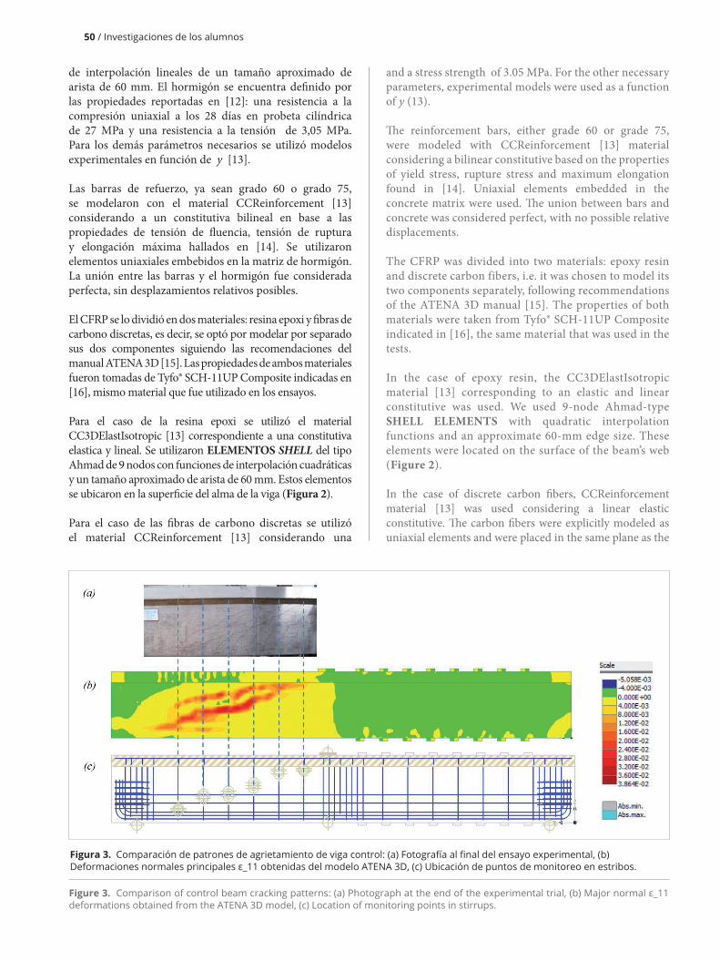
Figura 3. Comparación de patrones de agrietamiento de viga control: (a) Fotografía al final del ensayo experimental, (b) Deformaciones normales principales ε_11 obtenidas del modelo ATENA 3D, (c) Ubicación de puntos de monitoreo en estribos.
Figure 3. Comparison of control beam cracking patterns: (a) Photograph at the end of the experimental trial, (b) Major normal ε_11 deformations obtained from the ATENA 3D model, (c) Location of monitoring points in stirrups.

constitutiva lineal elastica. Las fibras de carbono fueron modeladas explícitamente como elementos uniaxiales y fueron ubicadas en el mismo plano del elemento shell que representa la resina epoxi (Figura 2). Se aplicó un numero arbitrario de fibras, pero el área de cada fibra fue determinada tal que produzca una rigidez en el elemento compuesto igual a la rigidez compuesta especificada en Tyfo® SCH-11UP [16].
Se realizó un análisis del tipo PUSHOVER estático con incrementos de desplazamiento. El análisis consideró no linealidad geométrica y fue del tipo ARC LENGTH donde se utilizó los parámetros recomendados por defecto en ATENA 3D.
3. RESULTADOS Y DISCUSIÓN
3.1 Patrones de agrietamiento
El agrietamiento diagonal observado en los experimentos al nivel de carga final y las deformaciones calculadas con el modelo de elementos finitos, se muestran: en la Figura 3 para la viga control (no reforzada) y en la Figura 4 para la viga reforzada con CFRP. Se observa que ATENA 3D logra capturar zonas de agrietamiento similares a las vistas en los ensayos experimentales. Los modelos ATENA 3D muestran una mayor concentración de deformaciones en una zona cercana a donde se observa agrietamiento en los modelos experimentales. Los estribos y bandas de CFRP ubicados al centro de la zona ensayada experimentan una mayor solicitación; pero, independiente del tipo de refuerzo de la
shell element that represents the epoxy resin (Figure 2). An arbitrary number of fibers was applied, but the area of each fiber was determined so that it produced a rigidity in the composite element equal to the composite rigidity specified in Tyfo® SCH-11UP [16].
A static PUSHOVER-type analysis was performed with displacement increments. The analysis considered geometric non-linearity and was of the ARC LENGTH-type, and recommended ATENA 3D default parameters were used.
3. RESULTS AND DISCUSSION
3.1 Cracking patterns
The diagonal cracking observed in the experiments at the final load level and the deformations calculated with the finite-element model are shown in Figure 3 for the control beam (not reinforced) and in Figure 4 for the CFRP-reinforced beam. It is observed that ATENA 3D manages to capture cracking areas similar to the ones observed in the experimental tests. The ATENA 3D models show a higher concentration of deformation in an area close to where cracking is observed in the experimental models. CFRP stirrups and strips located at the center of the tested area experience increased stress; but independently of the beam reinforcement type, the crack retains its shape and crosses
Students’ research / 51
Figura 4. Comparación de patrones de agrietamiento de viga reforzada con CFRP: (a) Fotografía al final del ensayo experimental, (b) Deformaciones normales principales obtenidas del modelo ATENA 3D, (c) Ubicación de puntos de monitoreo en estribos y fibras de carbono.
Figure 4. Comparison of CFRP-reinforced beam cracking patterns: (a) Photograph at the end of the experimental trial, (b) Major normal deformations obtained from the ATENA 3D model, (c) Location of monitoring points on stirrups and carbon fibers.

all CFRP stirrups and strips in the area that was studied.
The computational model manages to identify greater dispersion in the concentration of deformations in the control beam, just like the experimental test, in which several cracks of small thickness are observed (Figure 6). At the same time, the concentration of deformations in the reinforced beam is clearly delimited to a defined area, just like the experimental test, where a crack of great thickness is observed (Figure 7).
3.2 Load-Deformation Curves
Figure 5 shows deflection vs. load curves, both measured and calculated, for the control beam (not reinforced) and for the CFRP-reinforced beam. The maximum load measured in the control beam was 1.0 MN, while in the reinforced beam it reached approximately 1.9 MN. The response of the control beam has an approximately linear first part up to 0.2 MN, whereas the rigidity degrades at greater loads. On the other hand, the reinforced beam has a linear response up to a larger load, 0.6 MN. For greater loads the beam maintains linear behavior up to approximately 1.6 MN.
It is observed that the curve obtained from ATENA 3D corresponding to the beam that was not reinforced is very close to the experimental curve, capturing the initial rigidity, the load at which linear behavior is lost, and maximum resistance and ultimate deformation. On the other hand, the ATENA 3D curve reproduces very well the initial rigidity, the point at which rigidity changes and subsequent rigidity. It is not able to estimate either the maximum strength or the ultimate deformation, since it fails at 1.4 MN. In the ATENA 3D models, the test was considered finished when the program detected convergence problems in the response. These convergence problems occurred in
52 / Investigaciones de los alumnos
viga, la grieta conserva su forma y atraviesa todos los estribos y bandas de CFRP de la zona estudiada.
El modelo computacional logra identificar una mayor dispersión en la concentración de deformaciones en la viga no reforzada tal como ocurre en el ensayo experimental, donde se observa varias grietas de poco espesor (Figura 6). Al mismo tiempo, la concentración de deformaciones en la viga reforzada está claramente demarcada en un área definida tal como ocurre en el ensayo experimental, donde se observa una grieta de gran espesor (Figura 7).
3.2 Curvas Carga Deformación
En la Figura 5 se presentan las curvas deflexión vs carga, tanto medidas como calculadas, para la viga control (no reforzada) y la viga reforzada con CFRP. La carga máxima medida en la viga control fue 1,0 MN, mientras que en la viga reforzada se llegó hasta aproximadamente 1,9 MN. La respuesta de la viga control tiene una primera parte aproximadamente lineal hasta 0,2 MN, mientras que para cargas mayores la rigidez se va degradando. Por otro lado, la viga reforzada tiene una respuesta lineal hasta una carga mayor, 0,6 MN. Para cargas mayores la viga mantiene comportamiento lineal hasta aproximadamente 1,6 MN.
Se observa que la curva obtenida de ATENA 3D correspondiente a la viga no reforzada es muy cercana a la curva experimental, capturando la rigidez inicial, la carga para la que se pierde comportamiento lineal, y la resistencia máxima y deformación ultima. Por otro lado, la curva ATENA 3D reproduce muy bien la rigidez inicial, el punto de cambio de rigidez y la rigidez posterior. No es capaz de estimar bien la resistencia máxima ni la deformación ultima ya que falla a 1,4 MN. En los modelos de ATENA 3D, se consideró finalizado el ensayo cuando el programa detectaba problemas de convergencia en la respuesta. Estos
Figura 5. Curvas Carga Deformación: (a) Viga Control, (b) Viga Reforzada con CFRP.
Figure 5. Load-Deformation Curves: (a) Control Girder, (b) CFRP-Reinforced Girder.

problemas de convergencia ocurrieron en los elementos relacionados con la resina epoxi y la fibra de carbono. 3.3 Curvas de Contribución de Corte
Al ser una viga simplemente apoyada con una carga puntual, el corte total aplicado se puede obtener estáticamente. Dadas las dimensiones de la probeta (Figura 1) se tiene un corte de V(x)=0,554P, donde P es la carga puntual aplicada. Tanto para la viga control como para la viga reforzada, la contribución de los estribos y de las bandas de CFRP fue obtenida por medio de puntos de monitoreo de deformación ubicados en la zona de concentración de deformaciones observada en ATENA 3D (Figuras 3-4), mientras que la contribución del hormigón se obtuvo como la resta entre el corte total y el aporte de los estribos y bandas de CFRP (Vc
control=V-Vs,Vcreforzada=V-Vs-VCFRP).
En la Figura 6 se muestra el aporte de resistencia al corte del hormigón y de los estribos de acero en la viga control, medido en el experimento y calculados con ATENA 3D. Se observa la gran similitud entre las curvas de contribución al corte en la viga control. Las curvas calculadas logran capturar un instante de agrietamiento similar al de las curvas experimentales (cerca de P=0,6 MN), que corresponde al punto en el que aumenta bruscamente la fuerza en los estribos. También captura de forma cercana la evolución de los esfuerzos de corte, tanto en los estribos como en el hormigón, antes y después del agrietamiento. Se observa que el aporte de los estribos es nulo antes del agrietamiento, crece repentinamente durante el agrietamiento y llega a ser muy cercano al aporte del hormigón para el final del ensayo.
En la Figura 7 se muestran curvas de contribución de corte para la viga reforzada con CFRP. Se observa que las curvas calculadas logran capturar una contribución a corte de los estribos, bandas de CFRP y hormigón similar a las curvas
elements related to epoxy resin and carbon fiber.
3.3 Shear Contribution Curves
Being a simply supported beam with a point load, the applied total shear can be obtained statically. Given the dimensions of the test tube (Figure 1) we have a shear of V(x)=0.554P, where P is the applied point load. For both, control and reinforced beams, the contribution of the stirrups and the CFRP strips was obtained by means of deformation monitoring points located in the area of concentration of the deformations observed in ATENA 3D (Figures 3-4), while the concrete’s contribution was obtained as the subtraction between total shear and the contribution of the stirrups and CFRP strips (Vc
control=V-Vs,Vc
reinforced=V-Vs-VCFRP).
Figure 6 shows the contribution of shear strength for the concrete and steel stirrups in the control beam, measured in the experiment and calculated with ATENA 3D. Great similarity between the shear contribution curves in the control beam can be observed. The calculated curves manage to capture an instant of cracking similar to that of the experimental curves (around P=0.6 MN), which corresponds to the point in which the force on the stirrups increases abruptly. They also capture closely the evolution of shear efforts, both in the stirrups and concrete, before and after cracking. It is observed that the contribution of the stirrups is null before cracking, grows suddenly during cracking and becomes very close to the contribution of the concrete at the end of the test.
Figure 7 shows shear contribution curves for the CFRP-reinforced beam. It is observed that the calculated curves are able to capture a contribution to shear of the stirrups, CFRP strips and concrete, similar to the experimental
Students’ research / 53
Figura 6. Curvas de Contribución de Corte. Viga Control: (a) Modelo Experimental, (b) Modelo ATENA 3D.
Figure 6. Shear Contribution Curves. Control Beam: (a) Experimental Model, (b) ATENA 3D Model.
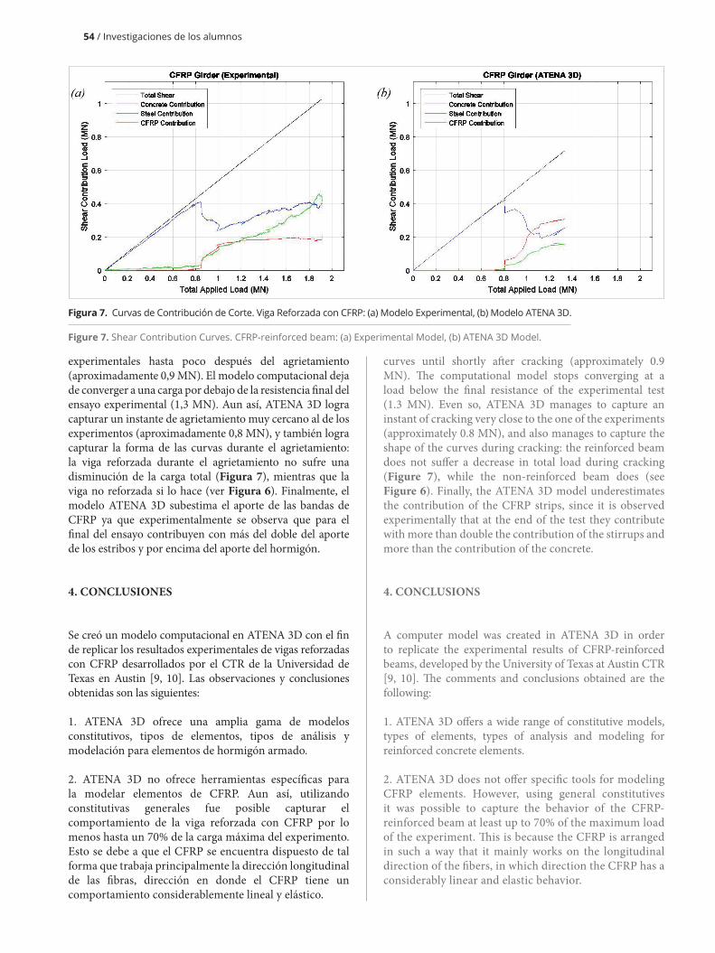
experimentales hasta poco después del agrietamiento (aproximadamente 0,9 MN). El modelo computacional deja de converger a una carga por debajo de la resistencia final del ensayo experimental (1,3 MN). Aun así, ATENA 3D logra capturar un instante de agrietamiento muy cercano al de los experimentos (aproximadamente 0,8 MN), y también logra capturar la forma de las curvas durante el agrietamiento: la viga reforzada durante el agrietamiento no sufre una disminución de la carga total (Figura 7), mientras que la viga no reforzada si lo hace (ver Figura 6). Finalmente, el modelo ATENA 3D subestima el aporte de las bandas de CFRP ya que experimentalmente se observa que para el final del ensayo contribuyen con más del doble del aporte de los estribos y por encima del aporte del hormigón.
4. CONCLUSIONES
Se creó un modelo computacional en ATENA 3D con el fin de replicar los resultados experimentales de vigas reforzadas con CFRP desarrollados por el CTR de la Universidad de Texas en Austin [9, 10]. Las observaciones y conclusiones obtenidas son las siguientes:
1. ATENA 3D ofrece una amplia gama de modelos constitutivos, tipos de elementos, tipos de análisis y modelación para elementos de hormigón armado.
2. ATENA 3D no ofrece herramientas específicas para la modelar elementos de CFRP. Aun así, utilizando constitutivas generales fue posible capturar el comportamiento de la viga reforzada con CFRP por lo menos hasta un 70% de la carga máxima del experimento. Esto se debe a que el CFRP se encuentra dispuesto de tal forma que trabaja principalmente la dirección longitudinal de las fibras, dirección en donde el CFRP tiene un comportamiento considerablemente lineal y elástico.
curves until shortly after cracking (approximately 0.9 MN). The computational model stops converging at a load below the final resistance of the experimental test (1.3 MN). Even so, ATENA 3D manages to capture an instant of cracking very close to the one of the experiments (approximately 0.8 MN), and also manages to capture the shape of the curves during cracking: the reinforced beam does not suffer a decrease in total load during cracking (Figure 7), while the non-reinforced beam does (see Figure 6). Finally, the ATENA 3D model underestimates the contribution of the CFRP strips, since it is observed experimentally that at the end of the test they contribute with more than double the contribution of the stirrups and more than the contribution of the concrete.
4. CONCLUSIONS
A computer model was created in ATENA 3D in order to replicate the experimental results of CFRP-reinforced beams, developed by the University of Texas at Austin CTR [9, 10]. The comments and conclusions obtained are the following:
1. ATENA 3D offers a wide range of constitutive models, types of elements, types of analysis and modeling for reinforced concrete elements.
2. ATENA 3D does not offer specific tools for modeling CFRP elements. However, using general constitutives it was possible to capture the behavior of the CFRP-reinforced beam at least up to 70% of the maximum load of the experiment. This is because the CFRP is arranged in such a way that it mainly works on the longitudinal direction of the fibers, in which direction the CFRP has a considerably linear and elastic behavior.
54 / Investigaciones de los alumnos
Figura 7. Curvas de Contribución de Corte. Viga Reforzada con CFRP: (a) Modelo Experimental, (b) Modelo ATENA 3D.
Figure 7. Shear Contribution Curves. CFRP-reinforced beam: (a) Experimental Model, (b) ATENA 3D Model.

Students’ research / 55
3. El modelo computacional logró capturar patrones de agrietamiento, curvas carga-deflexión y contribución de corte sin un costo computacional exagerado (los modelos demoraron en promedio 1 hora y media en concluir el análisis). ATENA 3D es una herramienta práctica de modelación que permite estudiar fenómenos difíciles de observar en ensayos experimentales.
AGRADECIMIENTOS
Los autores quisieran agradecer a Nawaf Alotaibi por proporcionar las curvas experimentales con las cuales se comparó el modelo computacional. También a William A. Shekarchi y Roya Abyaneh por la ayuda brindada en la modelación. Finalmente, a la Pontifica Universidad Católica de Chile por la ayuda brindada durante la estadía corta de investigación en la Universidad de Texas en Austin.
3. The computational model was able to capture cracking patterns, load-deflection curves and shear contribution without an exaggerated computational cost (the models took an average of 1 and a half hours to complete the analysis). ATENA 3D is a practical modeling tool that allows the study of phenomena that are difficult to observe in experimental tests.
ACKNOWLEDGEMENTS
The authors would like to thank Nawaf Alotaibi for providing the experimental curves with which the computational model was compared. Also, thanks to William A. Shekarchi and Roya Abyaneh for help provided in the modeling. Finally, thanks to the Pontifical Catholic University of Chile for the assistance provided during for the short research stay at the University of Texas at Austin.
GLOSSARY
STRAIN GAGES: deformation measurement sensors that consist of an electrical conductor that changes the value of its resistance as its geometry changes due to deformation of the material to which it is attached.FRACTURE-PLASTIC MODEL: concrete non-linear behavior model that combines constitutive models of stress fracture and plasticity under compression. It can detect cracking, crushing under high confinement and closing of cracks.BRICK ELEMENT: hexahedral three-dimensional finite element.SHELL ELEMENT: finite three-dimensional hexahedral elements such that their thickness is much smaller than the other two dimensions.PUSHOVER: successive incremental static and structural analysis in which the rigidity variation of the elements is taken into account.ARC LENGTH ANALYSIS: iterative incremental algorithm for solving equations or systems of equations that are non-linear.
GLOSARIO
STRAIN GAGES: sensor de medición de deformaciones, consiste en un conductor eléctrico que cambia el valor de su resistencia conforme cambia su geometría debido a la deformación del material al que va adherido.MODELO FRACTURE-PLASTIC: modelo de comportamiento no lineal del hormigón que combina de modelos constitutivos de fractura en tensión y plasticidad en compresión. Puede detectar agrietamientoELEMENTO BRICK: elemento finito tridimensional hexaédrico.ELEMENTO SHELL: elementos finito tridimensional hexaédricos donde su dimensión de espesor es mucho más pequeña que las otras dos dimensiones.PUSHOVER: proceso sucesivo de análisis estructural estático incremental donde se toma en cuenta la variación de rigidez de los elementos.ANÁLISIS ARC LENGTH: algoritmo incremental iterativo de resolución de ecuaciones o sistemas de ecuaciones no lineales.

56 / Investigaciones de los alumnos
PRINCIPIO CIENTíFICO
La Figura 8 muestra un esquema simplificado del mecanismo de un tipo de falla por esfuerzo de corte. A pesar de que los factores que influyen a la formación de grietas son numerosos y complejos, se ha observado experimentalmente que las grietas tienen una orientación vertical en la zona cercana al centro del vano y tienden a una orientación diagonal cerca de los apoyos (45° aproximadamente). Luego, para restringir el crecimiento de esas grietas es necesario utilizar una armadura de corte (estribos) al interior de la viga de HA, la que debe cruzar las grietas y estar bien ancladas a ambos lados de ellas. En casos donde esta armadura de corte ha sido sub dimensionada o las solicitaciones de corte tuvieron un incremento repentino, es necesario reforzar la viga externamente con materiales como el CFRP. De lo contrario la viga tendrá una falla frágil debida a corte mucho antes de desarrollar toda la capacidad a flexión para la que fue originalmente construida.
SCIENTIFIC PRINCIPLE
Figure 8 shows a simplified schematic of the mechanism corresponding to a type of failure caused by shear stress. Although the factors influencing the formation of cracks are numerous and complex, it has been experimentally observed that the cracks have a vertical orientation in the area near the center of the bay and tend towards a diagonal orientation near the supports (45° approximately). Therefore, in order to restrict the growth of these cracks, it is necessary to use a cutting armor (stirrups) inside the RC beam, which must cross the cracks and be well anchored on both sides of them. In cases in which this shear reinforcement has been undersized or in which the shear forces have increased suddenly, it is necessary to reinforce the beam externally with materials such as CFRP. Otherwise, the beam will undergo a brittle failure caused by shear, well before developing all the bending capacity for which it was originally built.
Figure 8. Shear transfer mechanisms in a CFRP-reinforced beam.
Figura 8. Mecanismos de transferencia de corte en una viga reforzada con CFRP.

Students’ research / 57
REFERENCES
[1] TENG, J., et al. FRP-strengthened RC Structures. Chichester, UK: John Wiley & Sons, LTD, 2002. ISBN 0-471-48706-6.[2] INTERNATIONAL FEDERATION FOR STRUCTURAL CONCRETE (fib). Bulletin 14: Externally bonded FRP reinforcement for RC structures. Lausanne, Switzerland, 2001.[3] AMERICAN CONCRETE INSTITUTE (ACI). Guide for the Design and Construction of Externally Bonded FRP Systems for Strengthening Concrete Structures (ACI 440.2R-08). Farmington Hills, MI, 2008.[4] CANADIAN STANDARDS ASSOCIATION (CSA). Design and Construction of Building Components with Fibre-Reinforced Polymers (CAN/CSA-S806-02). Ontario, Canada, 2002.[5] CONCRETE SOCIETY (CS). Design guidance on strengthening concrete structures using fibre composite materials (Technical Rep. No. 55). London, UK, 2004.[6] NATIONAL COOPERATIVE HIGHWAY RESEARCH PROGRAM (NCHRP). Design of FRP Systems for Strengthening Concrete Girders in Shear (NCHRP Report 678). Transportation Research Board. Washington, D.C., 2011.[7] NATIONAL RESEARCH COUNCIL (CNR) - Advisory Committee on Technical Recommendations for Construction. Guide for the Design and Construction of Externally Bonded FRP Systems for Strengthening Existing Structures (CNR-DT 200/2004). Rome, Italy, 2004.[8] NATIONAL COOPERATIVE HIGHWAY RESEARCH PROGRAM (NCHRP). Recommended Guide Specification for the Design of Externally Bonded FRP Systems for Repair and Strengthening of Concrete Bridge Elements (NCHRP Report 655). Transportation Research Board. Washington, D.C., 2010.[9] CANADIAN NETWORK OF CENTERS OF EXCELLENCE ON INTELLIGENT SENSING FOR INNOVATIVE STRUCTURES (ISIS). Strengthening reinforced concrete structures with externally-bonded fibre reinforced polymers (ISIS Canada Design Manual no. 4). Ontario, Canada, 2001.[10] Are Available Models Reliable for Predicting the FRP Contribution to the Shear Resistance of RC Beams? Sas et al. 6, , 2009, Vol. 13, pp. 514-534.[11] Shear behavior of full-scale reinforced concrete T-beams strengthened with CFRP strips and anchors. Kim, Ghannoum & Jirsa. 2015, Construction and Building Materials, Vol. 94, pp. 1-9.[12] KIM, Y., et al. Shear Strengthening of Reinforced and Prestressed Concrete Beams Using Carbon Fiber Reinforced Polymer (CFRP) Sheets and Anchors (FHWA/TX-12/0-6306-1). Texas Department of Transportation. Austin, TX : Center for Transportation Research, 2012.[13] CERVENKA, V., JENDELE, L., CERVENKA, J. ATENA Program Documentation. Part 1: Theory. Prague, Czech Republic: Cervenka Consulting, 2014. pp. 15-82.[14] Standard Specification for Deformed and Plain Carbon Steel Bars for Concrete Reinforcement (A615/A615M-16). American Society for Testing Materials (ASTM). West Conshohocken, PA, 2016.[15] PRYL, D., CERVENKA, J. ATENA Program Documentation. Part 11: Troubleshooting Manual. Prague, Czech Republic: Cervenka Consulting, 2014.[16] FYFE COMPANY. TYFO® SCH-11UP Composite using Tyfo® S Epoxy. [Online] 2015. [Cited: 8 9, 2016.] http://www.fyfeco.com/-/media/Files/Fyfe/2013-Products/Tyfo%20SCH%2011UP.ashx.
EQUIPO DE INVESTIGADORES / RESEARCH TEAM
Wassim M. Ghannoum
José Luis Jiménez
Hernán Santa María