
Portek TOC 2011 Presentation
59
1 Premature Crane Structure Failure & Finite Element Method Analysis and Rectification By SC Tok & Larry Lam / Portek Group
description
Tehnical
Transcript of Portek TOC 2011 Presentation
1
Premature Crane Structure Failure & Finite Element Method Analysis and Rectification
By SC Tok & Larry Lam / Portek Group

2

3
Overviews
Introduction of Portek• About Portek• Our Experience
Premature crane failuresApplication of FEM
• Crane Repair• Crane modification• Crane life assessment
Conclusions Q&A Session
4
Company History
• Established in 1988
• Turnkey provider of equipment, services and solutions to the global port industry.
• Expanded into port operations in 1999.
• Listed on the Mainboard of Singapore Stock Exchange in 2002.
• Headquartered in Singapore, with offices in locations across Asia, Europe and Africa employing over 1600 employees.
5
Core Businesses & CompetenciesPort Operations and Management
• Operate and manage 8 terminals globally
Equipment Engineering• Equipment sale and leasing • Mobilization, modification & modernization• Maintenance, diagnostics & repairs• Distribution of components and spares
Port IT Solutions• Container Terminal Management System (CTMS)• Equipment Maintenance System• Terminal Planning & Simulation• Radio Data Terminal System (RDTS)• Positioning Determining Systems (PDS)• Optical Character Recognition (OCR)

6
Terminal Ops & Management
Bejaia Mediterranean Terminal, Algeria
Valletta Gateway Terminals, Malta
Terminal 009, Jakarta
Terminal 300, Jakarta
Port D’Owendo, Libreville, Gabon
Port Gentil, Gabon
Banten Multipurpose Terminal, Java
Dry port in Kigali, Rwanda

7
IntroductionPremature failures of crane structure are becoming more common!
About 1.2m crack found at boom web plate

8
IntroductionPremature failures of crane structure are becoming more common!
Crack found at boom-girder hinge

9
IntroductionPremature failures of crane structure are becoming more common!
Incident of trolley wheel truck due to crack Serious wear on trolley rail

10
IntroductionPremature failures of crane structure are becoming more common!
Cracks at girder end Repair of forestay gusset plate: wear and cracks

11
IntroductionWhy do crane structures fail prematurely?
• Crane sizes have increased significantly. Weight of the crane has increased to 2000 ton versus 800 ton. Outreach of 65m versus 34 m.
• Crane speeds have also increased substantially.• Crane lift capacity increased from 40 ton to now 65 ton• Twinlift and tandem lift operation
Although modern design software and manufacturing process have helped crane manufacturers to optimize their design, there is still some degree of trial and error in any new crane design.

12
IntroductionWhy do crane structures fail prematurely?
• We are venturing into new territories which only time will tell as to how well crane structures can withstand heavier duties they are subject to
• Most crane designs are based on experiences and data gathered.• Static + dynamic factor• Not enough study on the dynamic characterization of super
sized crane. In some design cases, 1 loading cycle actually generate 20 oscillations, hence causing the fatigue cycles to be reached well before intended life cycle.
• Need to determine if manufacturing quality problem or inherent design problem.

13
Premature crane failure
Manufacturing Quality – a major factor
• Low cost country with cheaper labour
• Even within the same country, there was a case of an establishedmanufacturer who suffered quality problems after transferring crane manufacturing to different factory using sub-contract labour.
• Employing 3rd party inspection helps, but cannot eliminate all problems

14
Procurement considerations
• Procurement decision increasingly governed by short term financial considerations – pennywise, pound foolish
• True cost of a crane is life cycle cost : depreciation plus maintenance plus performance consideration.
• Examples: cranes are scrapped after 10 years of problematic service life. These are the most expensive cranes, no matter how cheap they are in beginning.
15
Purchase considerations
• With raw materials and energy cost rising, days of cheap cranes will soon be over. Inflationary pressures and rising labour cost in low cost countries are putting upward pressures on crane prices.
• Port Operators will have to squeeze productivity and make assetssweat for them
• Life cycle factors such as reliability, availability, energy consumption, maintenance cost, will feature more prominently in purchaser consideration.
• Safety of crane operation has been largely overlooked, and not accorded enough consideration. Reputational damage.

16
Practical difficulties with crane shutdown for repairs and upgrade
• Operational needs always take priority over engineering tasks. Frequent delays to project execution
• Operationally difficult to isolate cranes in between other cranes. Skidding back and pushing it to end of the quay may be only solution.
• “Boom down” position could be achieved owing to vessel movements

17
IntroductionWhat are the common types of crane structure failures?
• Trolley structures• Boom-girder joints• Trolley rail• Crane leg structure• Gusset plate of forestay• Main equalizer beam• Rope sheave supports• others
Many failures caused by premature fatigue well before reaching design lifecycle!
18
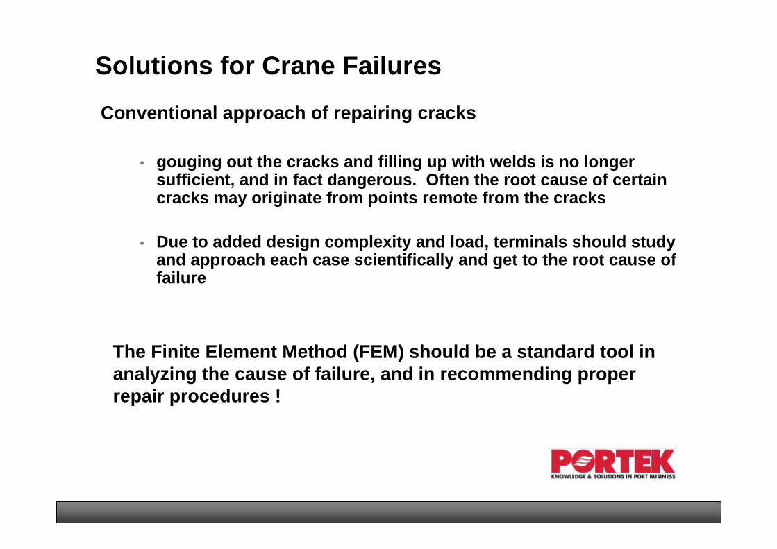
Solutions for Crane FailuresConventional approach of repairing cracks
The Finite Element Method (FEM) should be a standard tool in analyzing the cause of failure, and in recommending proper repair procedures !
• gouging out the cracks and filling up with welds is no longer sufficient, and in fact dangerous. Often the root cause of certain cracks may originate from points remote from the cracks
• Due to added design complexity and load, terminals should study and approach each case scientifically and get to the root cause of failure

19
What is FEA
Finite Element Analysis (FEA) is a way to simulate loading conditions on a design and determine the design’s response to those conditions.
The design is modeled using discrete building blocks called elements.
• Each element has exact equations that describe how it responds to a certain load.
• The “sum” of the response of all elements in the model gives the total response of the design.
• The elements have a finite number of unknowns, hence the name finite elements.
20
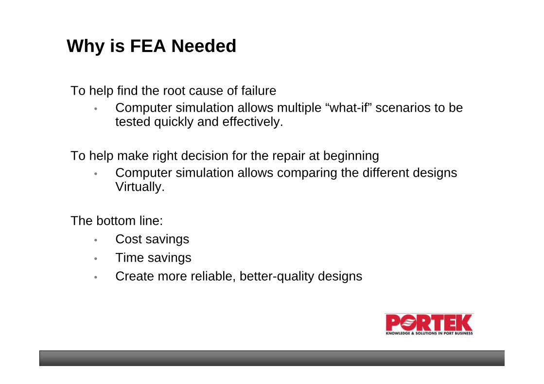
Why is FEA Needed
To help find the root cause of failure• Computer simulation allows multiple “what-if” scenarios to be
tested quickly and effectively.
To help make right decision for the repair at beginning• Computer simulation allows comparing the different designs
Virtually.
The bottom line:• Cost savings• Time savings• Create more reliable, better-quality designs

21
Application of FEM in Portek
• Transportation• Sea fastening design• Deck strength• Quay strength
• Crane modification
• Crane repair
• Crane life assessment
22
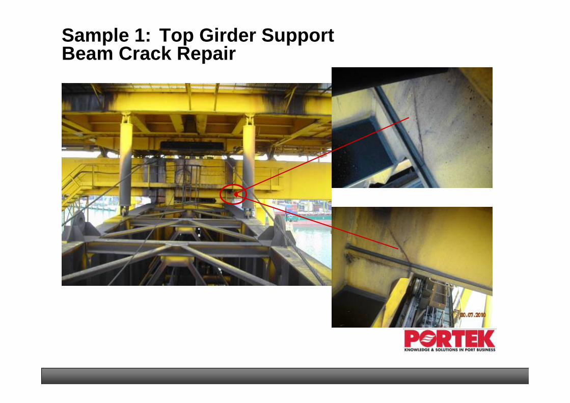
Sample 1: Top Girder Support Beam Crack Repair

23
Modeling of the affected areas Using FEM
24
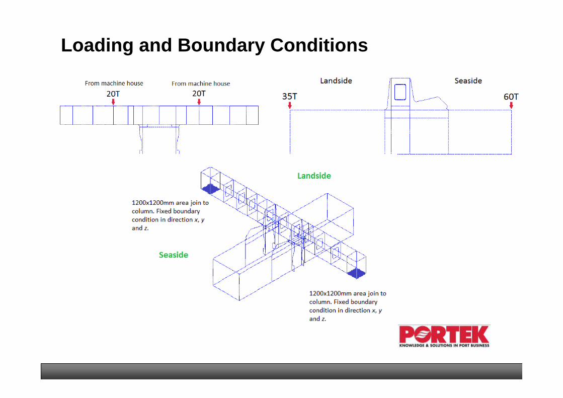
Loading and Boundary Conditions

25
Simulation Results for Original Design
26
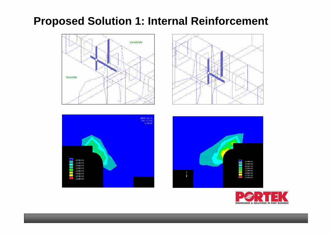
Proposed Solution 1: Internal Reinforcement

27
Very High StressVery High Stress
Proposed Solution 2: to Remove Sharp Edges
Improper design caused stress migration!

28
Selected Solution Using Finite Element Method!
Proposed Solution 3: Smooth Curve w/o Sharp Edges

29
15%142Seaside right bottom
46%115Seaside right top
29%168Seaside left bottom
52%125Seaside left top
23%98Landside right bottom
37%88Landside right top
29%132Landside left bottom
44%102Landside left top
Stress reductionStress value (MPa)
Stresses
Maximum stresses found on the hanger plates and stress reduction as compared to the original design
Interpretation of Results

30
Site Execution of Repair
31
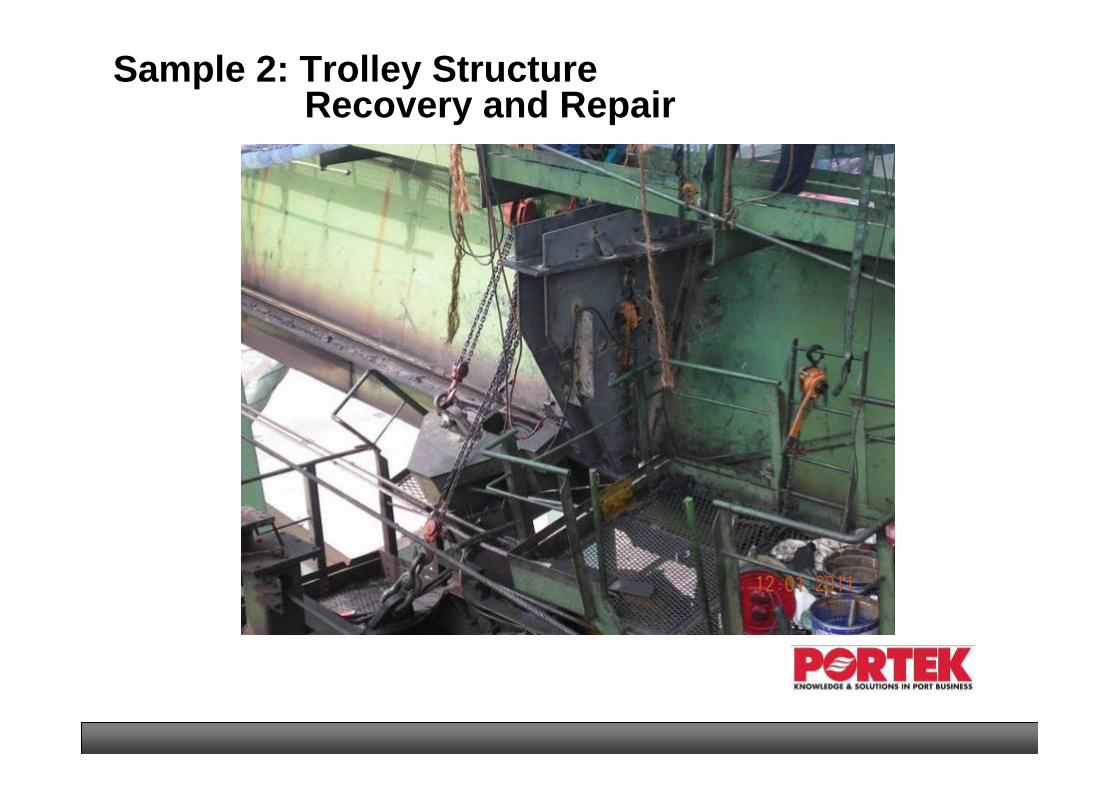
Sample 2: Trolley StructureRecovery and Repair

32
Trolley Structure Recovery
William Rod
33
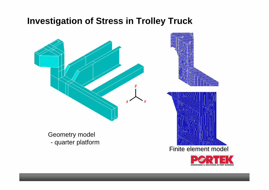
Investigation of Stress in Trolley Truck
Geometry model- quarter platform
Finite element modelFinite element model
34
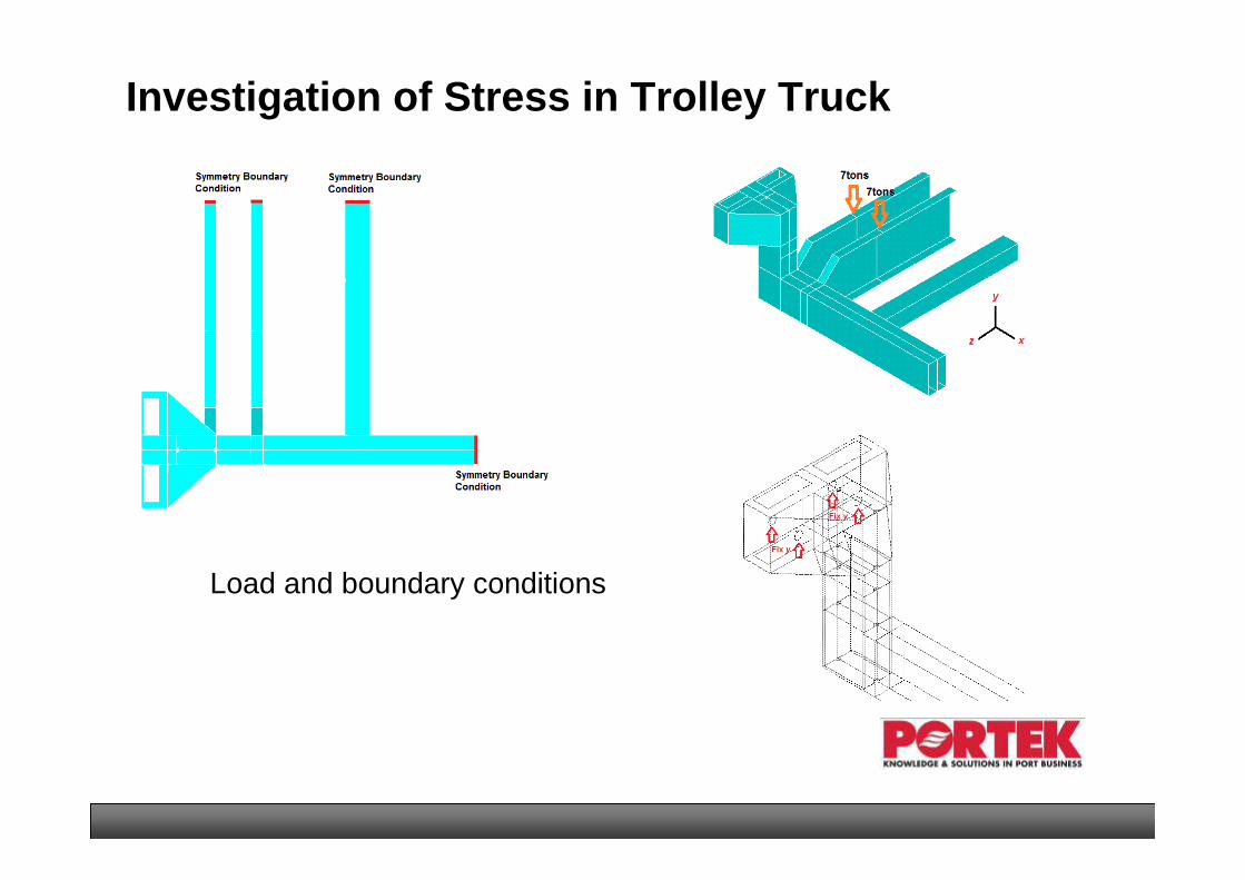
Load and boundary conditions
Investigation of Stress in Trolley Truck

35
Different boundary conditions to Different boundary conditions to investigate the reason of failureinvestigate the reason of failure
Investigation of Stress in Trolley Truck

36
structure under uniform constrain structure under wheel truck bend
One of the proposed modification under uniform constrain--worse
Investigation of Stress in Trolley Truck
Conclusions:
1. Major cause is the wheel truck bend along the rail direction
2. Boom-girder joint maintenance is very important
3. Trolley truck with equalizer pin is the efficient way to avoid this kind failure

37
Angle ofmisalignment
= 0°20’11”
Angle ofmisalignment
= 0°25’30”
Off by 53mmat 0m
Off by 109mmat 0m
Designed centreline of leg
Measured centreline of leg
Sample 3: Structure Repair of RTG

38
Normal Gantry Tyre Position
Gantry Tyre Position for damaged RTG
Far side
Far side
Near side
Near side
Sample 3: Structure Repair of RTG
39
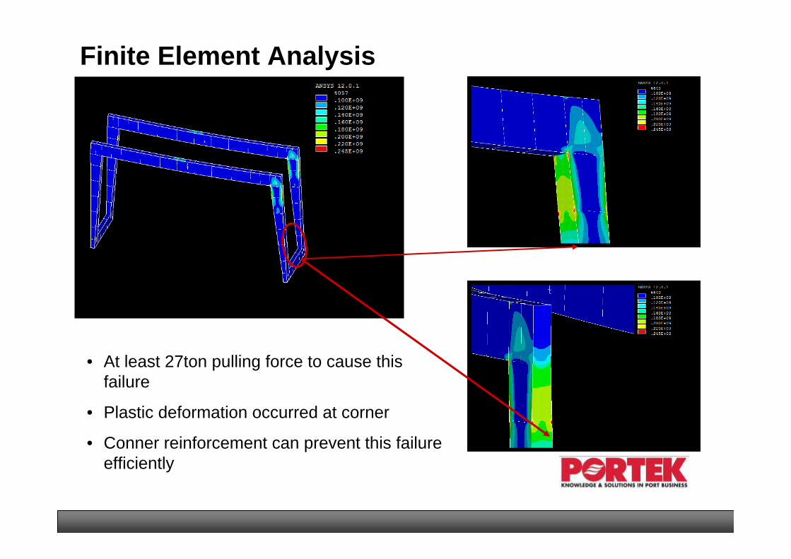
Finite Element Analysis
• At least 27ton pulling force to cause this failure
• Plastic deformation occurred at corner
• Conner reinforcement can prevent this failure efficiently

40
Repair Procedure

41
Structure Repair
42
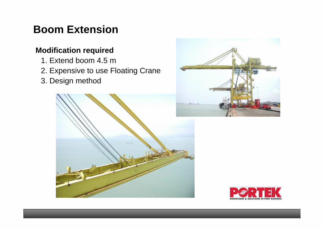
Boom Extension
Modification required1. Extend boom 4.5 m2. Expensive to use Floating Crane3. Design method

43
FE Simulation
Solver: ANSYS/Mechanical
Elements: PlateBeamBarJoint
Models:1. Original boom 2. Extended boom without moving lug3. Extended boom by moving lug

44
Simulation results & Comparison
45
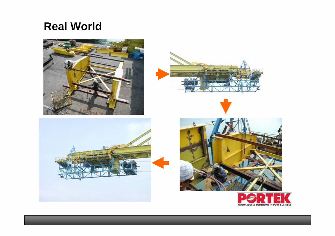
Real World

46
Height Extension Using Synchronise Jacking System
Modifications
1. Increase height 5.0 m
2. Strength & stability of jacking tower
3. Design method

47
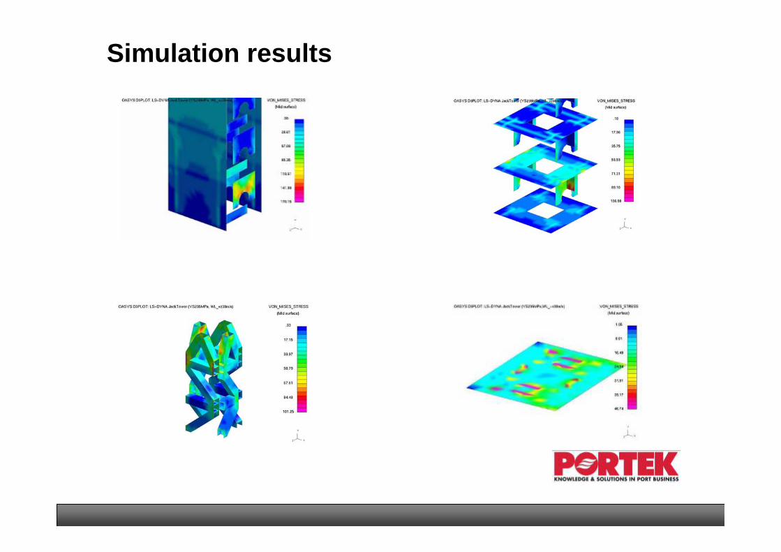
FE Simulation
Solver: LS_DYNA
Model: Inner tower & Jacking components
Key point: Multi-surface contact
Loads:1. Overall crane weight 2. Lateral wind

48
Simulation Results
49
Simulation results

50
Facing the Real World
Components to equipment
Jack up 1 m
Jack up 5 m&
Insert new leg

51
Simulation vs. Design
The jacking procedure is safe despite contact stresses are high;
The stress on the pin is quite low;
Local modification of the jacking section is suggested.

52
Useful Life Assessment
1. Structural Condition Survey
2. Useful Life Estimate Before Inspection
3. Structural Inspection
4. Useful Life Estimate After Inspection

53
• Many Cranes are at the end of their designed life cycle
• Fatigue cracks will occur and can be catastrophic if not repaired
• Crack repairs are often inexpensive and cracking can be controlled by proper analysis, design, workmanship, quality control and maintenance
• It is prudent to perform structural inspection prior to spending huge amount of money on refurbishment and drive retrofitting
Crane Structural Inspection, Why?

54
Structural Condition Survey
• Look for:
• High stress areas• Suspect details• Attachments
• Make photo record for the NDT inspection.

55
Useful Life Estimate Before Inspection
• Perform finite element analysis• Calculate relative cumulative damage• Estimate remaining useful life
Forestay failure analysis using ANSYS

56
Structural Inspection
Leg #2Leg #1
Leg #3
Leg #4
N-4
N-3
N-2
N-5
N-6
N-7
N-8
N-9N-10
• Inspect and compare with predictions
• Non-Destructive Test (NDT)
• Repair procedures

57
Useful Life Estimate After Inspection
• Review inspection reports
• Identify fatigue cracks
• Compare identified cracks with prediction
• Re-evaluate the reliability and useful life

58
Conclusions
• Finite Element Analysis is an essential tool for helping us in determining the cause of the problems and recommending the solutions.
• FEM analysis of structural failure should be adopted as standardtool in failure analysis
• With a trained engineer, FEM is quick and easy to deploy.
• With the exponential increase in computing power, FEM is economical to carry out.

59
Thank you