
proyecto de ejecución REFORMA DE SIST. DE REGULACIÓN Y ...
266
DIRECCIÓN DE ARQUITECTURA PROYECTO DE EJECUCIÓN DE MEJORA DE EFICIENCIA ENERGÉTICA MEDIANTE REFORMA DE SISTEMA DE REGULACIÓN Y CONTROL DE INSTALACIÓN DE CLIMATIZACIÓN EN PALACIO DE MORLANES SERVICIO DE CONSERVACIÓN DE ARQUITECTURA UNIDAD: UNIDAD DE ENERGÍA E INSTALACIONES INGENIERO INDUSTRIAL: Alberto Hernández Bernad. Colegiado nº 2453 COIIAR ASISTENCIA EXTERNA INGENIERO T. INDUSTRIAL: Iván Marzo Lario FUNCIONARIO MUNICIPAL MARZO / 2019 19 - 016 CHI MORLANES EFIC ICL
Transcript of proyecto de ejecución REFORMA DE SIST. DE REGULACIÓN Y ...

DIRECCIÓN DE ARQUITECTURA
PROYECTO DE EJECUCIÓN
DE MEJORA DE EFICIENCIA ENERGÉTICA MEDIANTE REFORMA DE SISTEMA DE REGULACIÓN Y CONTROL DE INSTALACIÓN DE CLIMATIZACIÓN EN PALACIO DE MORLANES
SERVICIO DE CONSERVACIÓN DE ARQUITECTURA
UNIDAD: UNIDAD DE ENERGÍA E INSTALACIONES
INGENIERO INDUSTRIAL: Alberto Hernández Bernad. Colegiado nº 2453 COIIAR ASISTENCIA EXTERNA
INGENIERO T. INDUSTRIAL: Iván Marzo Lario FUNCIONARIO
MUNICIPAL
MARZO / 2019
19 - 016 CHI MORLANES EFIC ICL

MEJORA DE LA EFICIENCIA ENERGÉTICA MEDIANTE REFORMA DE SISTEMA DE REGULACIÓN Y CONTROL DE INSTALACION DE CLIMATIZACÍON EN CASA PALACIO DE MORLANES 19 - 016 CHI MORLANES EFIC ICL
INDICE:
MEMORIA MEMORIA TÉCNICA DE LA INSTALACIÓN PLIEGO DE CONDICIONES ESTUDIO BÁSICO DE SEGURIDAD Y SALUD MEDICIONES Y PRESUPUESTO PLANOS
MEJORA DE LA EFICIENCIA ENERGÉTICA MEDIANTE REFORMA DE SISTEMA DE REGULACIÓN Y CONTROL DE INSTALACION DE CLIMATIZACÍON EN CASA PALACIO DE MORLANES 19 - 016 CHI MORLANES EFIC ICL
MEMORIA

MEJORA DE LA EFICIENCIA ENERGÉTICA MEDIANTE REFORMA DE SISTEMA DE REGULACIÓN Y CONTROL DE INSTALACION DE CLIMATIZACÍON EN CASA PALACIO DE MORLANES 19 - 016 CHI MORLANES EFIC ICL
INDICE
MEMORIA GENERAL
1. ANTECEDENTES Y OBJETO
2. ENCARGO DE LA MEMORIA
3. CONDICIONES URBANISTICAS
4. AUTOR DE LA MEMORIA
5. PLAZO EJECUCIÓN DE LA OBRA
6. JUSTIFICACIÓN ECONOMICA Y AHORRO ENERGÉTICO
7. MEMORIA JUSTIFICATIVA Y FICHA TÉCNICA
7.1 Memoria Justificativa
7.2 Ficha Técnica
8. NORMATIVA DE APLICACION
9. SOLUCIONES PROPUESTAS Y CONSIDERACIONES
10. MEMORIA DE LA INSTALACIÓN
11. NORMAS DE EJECUCION DE LAS INSTALACIONES
12. PRUEBAS REGLAMENTARIAS
13. CONDICIONES DE USO, MANTENIMIENTO Y SEGURIDAD
14. PLIEGO DE CONDICIONES
15. SEGURIDAD Y SALUD LABORAL
16. EXPRESION DEL PRESUPUESTO
MEMORIA TECNICA DE LA INSTALACIÓN
PLIEGO DE CONDICIONES
ESTUDIO BÁSICO DE SEGURIDAD Y SALUD
MEDICIONES Y PRESUPUESTO
PLANOS

MEJORA DE LA EFICIENCIA ENERGÉTICA MEDIANTE REFORMA DE SISTEMA DE REGULACIÓN Y CONTROL DE INSTALACION DE CLIMATIZACÍON EN CASA PALACIO DE MORLANES 19 - 016 CHI MORLANES EFIC ICL
MEMORIA GENERAL
1. ANTECEDENTES Y OBJETO
El edificio objeto del presente proyecto, denominado Casa Palacio de los Morlanes se
encuentra ubicado en la plaza San Carlos nº 3 de Zaragoza y alberga los Servicios Sociales
Comunitarios y Especializados, Servicio de Juventud y la filmoteca de Zaragoza. Tiene tres
plantas sobre rasante y un sótano destinado a salas técnicas.
Dentro de los edificios del Ayuntamiento de Zaragoza constituye uno de los que mayor gasto
energético tienen en relación con la superficie y uso al que está destinando, asociando dicho
exceso a una falta o defecto de control de las instalaciones que, por sus características,
deberían presentar elevados niveles de rendimiento.
El alcance del presente proyecto consiste en la instalación de un nuevo sistema de control
con el fin de mejorar la eficiencia energética del edificio, mediante la integración de nuevos
autómatas, sondas y elementos de campo para la optimización del consumo energético de
la instalación, además de adaptar al máximo la demanda de energía térmica del edificio a la
producción térmica de acuerdo con la instalación existente en la actualidad.
2. ENCARGO DEL PROYECTO
El presente Proyecto, se redacta siguiendo las instrucciones cursadas al efecto por la
Dirección de Arquitectura.
Al estar los trabajos a realizar en esta área, dentro de “Certificación de Calidad” se
la ha asignado el código 19 - 016 CHI MORLANES EFIC ICL
3. CONDICIONES URBANÍSTICAS
Las modificaciones previstas en las instalaciones no modifican las condiciones urbanísticas.

4. AUTOR DEL PROYECTO
Es autor del presente Proyecto, Alberto Hernández Bernad, Ingeniero Industrial al servicio
de Dolmen Ingenieria S.L.P. como Asistencia Técnica Externa en colaboración Iván Marzo
Lario, Ingeniero Técnico Industrial, de la Unidad de Energía e Instalaciones del Servicio de
Conservación de Arquitectura del Ayuntamiento de Zaragoza, actuando en calidad de
funcionario municipal.
5. PLAZO EJECUCIÓN DE LA OBRA
El plazo de ejecución de la obra será de 3 meses desde la firma del acta de replanteo.
6. JUSTIFICACIÓN ECONÓMICA Y AHORRO ENERGÉTICO
Con la inversión realizada se prevé la instalación de un sistema moderno y eficiente, que
contribuya lo menor posible al calentamiento global y que sus emisiones de CO2 sean
mínimas.
El ahorro de energía mediante la integración de un sistema adecuado de regulación y
control, de acuerdo con la bibliografía existente se estima en un 15 % equivalente a 25500
kw.h.
Los cálculos justificativos se encuentran en la memoria técnica del proyecto.
7. MEMORIA JUSTIFICATIVA Y FICHA TÉCNICA
Las consideraciones a tener en cuenta en la realización de estos Proyectos y su
correspondiente ejecución posterior son las siguientes:
7.1 Memoria Justificativa
Tipo de necesidad: Obra
Justificación de la necesidad: Dar cumplimiento a la Directiva 2010_27_UE del
Parlamento Europeo y del Consejo en materia de Eficiencia Energética y como actuación
dentro del Programa de Ahorro Energético 2015-2020 del Excmo. Ayuntamiento de
Zaragoza.
Aplicación presupuestaria: El presupuesto asciende a la cantidad de 48.356,52 euros, IVA
incluido, con cargo a la partida "Plan de Ahorro de Energía"

7.2 Ficha Técnica
Tipo de necesidad: Obra
Objeto del contrato: Obras de reforma de instalación de control de climatización.
Descripción servicio/obra/suministro: Reforma de instalación de control de climatización.
Precio del contrato: 48.356,52 EUROS (I.V.A. INCLUIDO)
Criterios de adjudicación: Se utilizará el criterio de baja lineal ofertada.
Otras condiciones de adjudicación: No aplica.
8. NORMATIVA DE APLICACIÓN
A las instalaciones proyectadas le son de aplicación las reglamentaciones siguientes:
• Real Decreto 1027/2007, de 20 de julio, por el que se aprueba el Reglamento de
instalaciones Térmicas en los Edificios (RITE).
• Real Decreto 314/2006, de 17 de marzo, por el que se aprueba el Código Técnico de la
Edificación.
• Real Decreto 865/2003 de 4 de julio, por el que se establecen los criterios higiénicos-
sanitarios para la prevención y control de la Legionelosis.
• Real Decreto 842/2002, de 2 de agosto, por el que se aprueba el Reglamento Electrónico
para baja Tensión e Instrucciones Complementarias.
• Ordenanza municipal Protección Contra Incendios de Zaragoza. BOP 17/06/2000
• Reglamento de Instalaciones de PCI. RD 1942/1993, de 5 de noviembre de 1993.
• Ordenanza municipal Protección Contra Ruidos y Vibraciones. Aprobada por el ayuntamiento
pleno el 31/01/2001.
• Reglamento de Seguridad e Higiene en el Trabajo según Decreto 432/1971 de 11 de marzo
y Orden de 9 de marzo de 1.971 por la cual se aprueba la Ordenanza General de Seguridad e
Higiene en el Trabajo.
• Ley 31/1995, de 8 de noviembre, de Prevención de Riesgos Laborales.
• Real Decreto 486/1997, Disposiciones mínimas de Seguridad y Salud en lugares de trabajo.
• Real Decreto 485/1997, Disposiciones mínimas en Materia de Señalización de Seguridad y
Salud en el Trabajo.
• Real Decreto 614/2001 de 8 de junio, sobre disposiciones mínimas para la protección de la
salud y seguridad de los trabajadores frente al riesgo eléctrico.
• Normas UNE de obligado cumplimiento.

9. SOLUCIONES PROPUESTAS Y CONSIDERACIONES
- Los trabajos incluidos en el presente proyecto, serán los siguientes:
Reforma de cuadro general de potencia para adaptación a nuevo sistema de
control y la integración de analizadores de redes y un variador de frecuencia.
Instalación de cuadros de control para la producción térmica, para los
climatizadores principales y para los climatizadores de aportación de aire.
Instalación de sondas de calidad de aire, humedad, temperatura y de agua para
la regulación del sistema manteniendo todos aquellos elementos actuales que se
encuentre en correcto estado y sea posible su integración en el nuevo sistema de
control, incluso analizadores de redes y contador de energía térmica.
Instalación de termostatos de control individual por fancoils.
Tendido de red modbus para la integración de todos los sistemas de control y
elementos de campo.
Programación y control de la instalación completa, incluyendo los climatizadores
con sus modos de funcionamiento (normal, mezcla, free-cooling), fan-coils,
variador de frecuencia de pozo y elementos de campo.
- En apartado posterior se definen en detalle los trabajos a realizar.
10. MEMORIA DE LA INSTALACIÓN
Seguidamente se detallan los trabajos a realizar en las distintas fases, indicándose en el
presupuesto y planos las características de los distintos materiales.
Trabajos Previos
- Reforma cuadro general de potencia: Sustitución de 34 selectores 0/1 por selectores
manual/0/auto para el control remoto de bombas y climatizadores. Instalación de 9
contactores para control remoto de los fancoils. Instalación de bornero de
interconexión a cuadro de control. Saneado de lámparas de puerta. Limpieza y
saneado de interior de cuadro.
- Desmontaje de elementos actuales fuera de uso tras el proyecto.

Instalación de Cuadros de control
Cuadro control producción: Cuadro de poliéster estanco para alojar el autómata
WEB SERVER de control de producción, módulos de E/S y borneros de interconexión.
Alojara los siguientes circuitos eléctricos: Cto. toma corriente auxiliar y alumbrado interior.
Cto. Fuente alimentación 24 VDC 10 A. Cto. Reserva.
Selectores de control manual y automático de enfriadoras en puerta.
Piloto de indicación de estados.
Cuadro control 3 climatizadores: Cuadro de poliéster estanco para alojar autómata de
control de climatizadores, módulos de E/S y borneros de interconexión.
Alojara los siguientes circuitos eléctricos: Cto. toma corriente auxiliar. Cto. Fuente
alimentación 24 VDC 5 A.
Cuadro control climatizadores de aportación (2 uds): Cuadro de poliéster estanco para
alojar autómata de control de climatizadores, módulos de E/S y borneros de interconexión.
Alojara los siguientes circuitos eléctricos: Cto. toma corriente auxiliar. Cto. Fuente
alimentación 24 VDC 2,5 A.
Instalación de Elementos de campo:
Termostatos: Instalación de 22 termostatos con comunicación modbus y salida para control
de válvulas de fancoil.
Instalación de sondas de calidad ambiental, sondas exteriores, interiores ambientales y de
conducto así como sondas de temperatura de agua.
Instalación de variador de frecuencia para bomba de pozo y analizadores de redes para
control y contadores de energía térmica.
Instalación de dos analizadores de redes y un contador de energía térmica.
Instalación eléctrica
La instalación eléctrica que se requiere es exclusivamente la necesaria para alimentar los
sistemas de control descritos.
Seguridad y Salud

Elaboración de la documentación relativa a seguridad y salud requerida según la normativa
vigente así como las medidas que se precisan adaptar de acuerdo al Estudio de Seguridad y
Salud.
Gestión Documental
Elaboración de planos as-built de la instalación así como certificados y documentación del
instalador necesarios para su legalización ante Industria por la dirección facultativa. Entrega
de dossier fin de obra con todo lo relativo a la programación de los autómatas instalados así
como licencias y acceso libre a programas y variables.
11. NORMAS DE EJECUCIÓN DE LAS INSTALACIONES
- Todas las normas de construcción e instalación se ajustarán, en todo caso, a los planos,
mediciones y calidades que se expresan, así como a las directrices que la Dirección
Facultativa estime oportunas.
- Además del cumplimiento de lo expuesto, las instalaciones se ajustarán a las normativas
que le pudieran afectar, dadas por organismos oficiales.
- El acopio de materiales se hará de forma que estos no sufran alteraciones durante su
depósito en la obra, debiendo retirar y reemplazar todos los que hubieran sufrido alguna
descomposición o defecto durante su estancia, manipulación o colocación en la obra.
12. PRUEBAS REGLAMENTARIAS
- Una vez ejecutada la instalación, se procederá, por parte de la entidad acreditada por los
organismos públicos competentes, a la medición reglamentaria de valores especificados en
el Reglamento de Instalaciones Térmicas en los edificios y en el Reglamento Electrotécnico
de B.T.
- Durante el transcurso de las obras se realizará un Control de Calidad en instalaciones en
los siguientes ámbitos:
Control de calidad de los materiales
Control de calidad de los equipos
Control de calidad en el montaje
Control de calidad en las pruebas y puestas en marcha de las instalaciones.

- Junto con el control de calidad de cada una de las partes indicadas se rellenarán las
correspondientes fichas de control que se adjuntarán a los informes periódicos que se
realizarán en el transcurso de las obras.
CONTROL DE CALIDAD EN LOS EQUIPOS Y MATERIALES
Previa a la colocación de cualquier material o equipo de los previstos en proyecto se
requerirá el certificado correspondiente en el que se indiquen las características del producto
y se verificará su idoneidad en cuanto al cumplimiento de reglamentos y normativas por las
que se vea afectado.
CONTROL DE EJECUCIÓN DE LOS TRABAJOS A REALIZAR
En el control de la ejecución de las instalaciones se verificarán los siguientes aspectos:
Inicialmente se controlará el replanteo de huecos para el paso de instalaciones (conductos,
tuberías, chimeneas, bandejas…), huecos de ventilación (rejillas de toma de aire y
tracciones) y patinillos de instalaciones.
Se controlará que los trazados de las instalaciones coinciden con los previstos en proyecto y
se analizarán las distintas interferencias de unas instalaciones con otras, de tal forma que
los trazados sean ordenados y permitan un adecuado mantenimiento.
Se controlará el paso de instalaciones a través de elementos constructivos de tal forma que
los encuentros permitan la libre dilatación de las distintas instalaciones.
Se verificará que se colocan los soportes adecuados para cada una de las canalizaciones
ejecutadas, así como la correcta interdistancia entre soportes.
Se controlará la protección de los distintos tipos de tubería y el aislamiento en cuanto a tipo,
espesor, barrera de vapor y señalización del sentido de circulación.
Se verificará que se da cumplimiento a las especificaciones técnicas de proyecto así como a
las reglamentaciones que les afecten.
La revisión de los trabajos quedará reflejada en el informe mensual correspondiente y dicho
informe quedará recogido en la documentación de final de obra.
CONTROL DE CALIDAD EN LAS PRUEBAS
Se realizarán las pruebas reglamentarias para cada una de las instalaciones así como
cualquier otra prueba que solicite la dirección facultativa para verificar el correcto
funcionamiento de las instalaciones.

La empresa contratista rellenará un protocolo de pruebas en el que se indiquen todas las
pruebas efectuadas, los resultados de las mismas y la fecha de realización.
Durante la obra se realizarán pruebas parciales bajo la supervisión de la dirección facultativa
y al finalizar las pruebas de funcionamiento de los sistemas y subsistemas completos que
permitan verificar el correcto funcionamiento de las instalaciones.
13. CONDICIONES DE USO, MANTENIMIENTO Y SEGURIDAD
MANTENIMIENTO Y USO DE LA INSTALACIÓN DE CLIMATIZACIÓN
La instalación de climatización y ventilación se utilizará y mantendrá de conformidad con los
procedimientos que se establecen en la Normativa.
INSTRUCCIONES DE SEGURIDAD
Las instrucciones de seguridad serán adecuadas a las características técnicas de la
instalación concreta y su objetivo será reducir a límites aceptables el riesgo de que los
usuarios u operarios sufran daños inmediatos durante el uso de la instalación.
INSTRUCCIONES DE MANEJO Y MANIOBRA
Las instrucciones de manejo y maniobra, serán adecuadas a las características técnicas de
la instalación concreta y deben servir para efectuar la puesta en marcha y parada de la
instalación, de forma total o parcial, y para conseguir cualquier programa de funcionamiento
y servicio previsto.
INSTRUCCIONES DE FUNCIONAMIENTO
El programa de funcionamiento, será adecuado a las características técnicas de la
instalación concreta con el fin de dar el servicio demandado con el mínimo consumo
energético.
14. PLIEGO DE CONDICIONES
Se dispone en Anexo, del correspondiente Pliego de Condiciones para la ejecución de la
Obra.
15. SEGURIDAD Y SALUD LABORAL
Se redactará el correspondiente Estudio de Seguridad Laboral, de acuerdo al R.D. 1627/97

16. EXPRESIÓN DEL PRESUPUESTO
El presupuesto de los trabajos a realizar esta desglosado en las mediciones y
presupuesto adjunto, siendo el siguiente:
Presupuesto de ejecución material ……………………………………………… 33.583,25
13% Gastos generales …………………………………………………....……… 4.365,82
6% Beneficio Industrial ……………………………………..…..…………… 2.015,00
PRESUPUESTO DE CONTRATA …………………………….…………… 39.964,07
21% IVA …………………………………………………………….…………… 8.392,45
PRESUPUESTO TOTAL IVA INCLUIDO………………………………. …… 48.356,52
I.C. de Zaragoza, Marzo de 2019
El Ingeniero Industrial SERVICIO CONSERVACIÓN ARQUITECTURA Colegiado nº: 2453UNIDAD DE ENERGÍA E INSTALACIONES
El Funcionario Municipal
Fdo: Iván Marzo Lario Fdo: Alberto Hernández Bernad
Asistencia Técnica Externa

MEJORA DE LA EFICIENCIA ENERGÉTICA MEDIANTE REFORMA DE SISTEMA DE REGULACIÓN Y CONTROL DE INSTALACION DE CLIMATIZACÍON EN CASA PALACIO DE MORLANES 19 - 016 CHI MORLANES EFIC ICL
MEMORIA TÉCNICA DE LA INSTALACIÓN
PROYECTO DE MEJORA DE EFICIENCIA ENERGÉTICA
MEDIANTE REFORMA SISTEMA DE REGULACIÓN Y CONTROL
DE INSTALACIÓN DE CLIMATIZACIÓN EN CASA MORLANES
AYUNTAMIENTO DE ZARAGOZA
INDICE
1. OBJETO Y ALCANCE DEL PROYECTO...................................................................................................4
2. NORMATIVA DE APLICACIÓN...................................................................................................................4
3. AUTOR DEL PROYECTO ...............................................................................................................................5
4. IDENTIFICACIÓN DEL TITULAR ...............................................................................................................5
5. EMPLAZAMIENTO ............................................................................................................................................5
6. DESCRIPCIÓN DEL ESTABLECIMIENTO Y DE LA INSTALACIÓN TÉRMICA ACTUAL...5
7. DESCRIPCIÓN DE LA SOLUCIÓN ADOPTADA ..................................................................................7
8. PUNTOS DE CONTROL DE LA INSTALACIÓN...................................................................................9
9. REFORMA INSTALACIÓN DE CONTROL.......................................................................................... 10
10. EXIGENCIAS DE BIENESTAR E HIGIENE............................................................................................. 11
11. EXIGENCIAS DE EFICIENCIA ENERGETICA ...................................................................................... 12
12. INSTALACIÓN ELÉCTRICA EN BAJA TENSIÓN .............................................................................. 13
13. CONCLUSIONES.............................................................................................................................................. 13
ANEJO 1: DOCUMENTACIÓN TÉCNICA DE EQUIPOS
ANEJO 2: ESTUDIO DE GESTIÓN DE RESIDUOS
ANEJO 3: FOTOGRAFÍAS
MEMORIA

-
PROYECTO DE MEJORA DE EFICIENCIA ENERGÉTICA
MEDIANTE REFORMA SISTEMA DE REGULACIÓN Y CONTROL
DE INSTALACIÓN DE CLIMATIZACIÓN EN CASA MORLANES
AYUNTAMIENTO DE ZARAGOZA
I. MEMORIA
1. OBJETO Y ALCANCE DEL PROYECTO
Se redacta el presente documento con el fin de describir, valorar y justificar de forma
detallada la reforma del sistema de control y regulación de la instalación de climatización
del edificio denominado Palacio de Morlanes.
El alcance del presente proyecto consiste en la instalación de un nuevo sistema de control
con el fin de mejorar la eficiencia energética del edificio, mediante la integración de
nuevos autómatas, sondas y elementos de campo para la optimización del consumo
energético de la instalación, además de adaptar al máximo la demanda de energía térmica
del edificio a la producción frigorífica de acuerdo con la instalación existente en la
actualidad.
2. NORMATIVA DE APLICACIÓN
El proyecto se ha desarrollado teniendo en cuenta la siguiente reglamentación:
- Reglamento de Instalaciones térmicas en los edificios (RITE) y sus instrucciones
técnicas complementarias, según R.D. 1027/2.007 de 20 de julio.
- R.D. 865/2003 de 4 de julio, por el que se establecen los criterios higiénico
sanitarios para la prevención y control de la legionelosis.
- Norma UNE 60670 “Instalaciones receptoras de gas suministradas a una presión
máxima de operación (MOP) inferior o igual a 5 bar”
- Norma UNE 60601 “Salas de máquinas y equipos autónomos de generación de
calor o frío para cogeneración, que utilizan combustibles gaseosos”.
- Código Técnico de la Edificación.
- Ordenanza de Seguridad e Higiene en el Trabajo (O.M. de 9-3-1991)
- R.D. 1942/1993 de 5 de noviembre, por el que se aprueba el Reglamento de
Instalaciones de Protección contra Incendios.
- Reglamento Electrotécnico de Baja Tensión, según R.D. 842/2002 de 2 de agosto.
MEMORIA 4

PROYECTO DE MEJORA DE EFICIENCIA ENERGÉTICA MEDIANTE REFORMA SISTEMA DE REGULACIÓN Y CONTROL DE INSTALACIÓN DE CLIMATIZACIÓN EN CASA MORLANES AYUNTAMIENTO DE ZARAGOZA
3. AUTOR DEL PROYECTO
Los datos del autor que redacta el presente proyecto son los siguientes:
Nombre y apellidos: Alberto Hernández Bernad, colegiado nº: 2453, COIIAR
DNI: 25181671Y
Razón social: Dolmen Ingeniería S.L.P.
Domicilio social: Paseo Sagasta nº 17, 3º Derecha A. 50008 Zaragoza.
Funcionario Municipal: Ivan Marzo Lario
4. IDENTIFICACIÓN DEL TITULAR
Denominación o razón social: Ayuntamiento de Zaragoza
CIF: P5030300G
Domicilio social: Plaza de nuestra señora del Pilar. 50003 Zaragoza.
Datos del representante:
Nombre: Iván Marzo Lario
Teléfono: 976721910
Domicilio a efectos de notificaciones:
Ayuntamiento de Zaragoza, Servicio de Conservación de Arquitectura. Unidad de
Energía e Instalaciones. Vía Hispanidad 20, 50009 Zaragoza.
5. EMPLAZAMIENTO
El edificio objeto del presente proyecto se encuentra en la Plaza San Carlos nº 3 de
Zaragoza.
6. DESCRIPCIÓN DEL ESTABLECIMIENTO Y DE LA INSTALACIÓN TÉRMICA ACTUAL
El edificio, construido en el año 1955, tiene tres plantas sobre rasante y un sótano y
actualmente alberga los Servicios Sociales Comunitarios y Especializados, Servicio de
Juventud y la filmoteca de Zaragoza.
ANEJO 2 5

PROYECTO DE MEJORA DE EFICIENCIA ENERGÉTICA
MEDIANTE REFORMA SISTEMA DE REGULACIÓN Y CONTROL
DE INSTALACIÓN DE CLIMATIZACIÓN EN CASA MORLANES
AYUNTAMIENTO DE ZARAGOZA
PRODUCCION:
La instalación térmica de producción actual consta de dos enfriadoras agua/agua de 60
KW conectadas en paralelo que producen agua fría y caliente simultáneamente. Estas
enfriadoras están controladas actualmente con un autómata Siemens que establece el
orden de funcionamiento de las máquinas y las monitoriza a un nivel básico (alarmas y
numero de etapas conectadas).
Las propias enfriadoras regulan la temperatura del agua asignada mediante las etapas de
funcionamiento.
El control de las enfriadoras integra las seguridades de bombas encendidas, el sistema
manual/automático y el funcionamiento invierno/verano.
El sistema de bombeo es totalmente manual con selectores de marcha paro en la puerta
del armario de potencia.
El sistema de distribución de agua es a dos tubos para fancoils y climatizadores de
aportación y a cuatro tubos para los climatizadores.
CLIMATIZADORES:
Existen tres climatizadores para las estancias más grandes (salón de actos, exposiciones y
planta sótano). Son totalmente autónomos con un control para cada uno, tienen instalada
una batería de agua caliente y otra de agua fría, así como módulo de mezcla de aire
exterior con posibilidad de free-cooling.
CLIMATIZADORES DE APORTACION DE AIRE:
Existen dos climatizadores para aportación de aire exterior a todo el edificio con una
cabina de extracción asociada. El climatizador tiene instalada una batería de agua para
climatizar el aire exterior, así como seguridad contra heladas.
FANCOILS ESTANCIAS:
El resto de estancias están climatizadas a través de fancoils a dos tubos controlados por
una sonda de temperatura en la sala. La consigna de temperatura la reciben del cuadro
general, así como el cambio de las condiciones de trabajo de invierno a verano.
7. DESCRIPCIÓN DE LA SOLUCIÓN ADOPTADA
El objeto de la reforma es poder monitorizar y controlar la instalación completa de
climatización desde un puesto centralizado mediante un Webserver.
MEMORIA 6

PROYECTO DE MEJORA DE EFICIENCIA ENERGÉTICA
MEDIANTE REFORMA SISTEMA DE REGULACIÓN Y CONTROL
DE INSTALACIÓN DE CLIMATIZACIÓN EN CASA MORLANES
AYUNTAMIENTO DE ZARAGOZA
El autómata a instalar es de la marca Wago. Consta de un módulo de cabecera que hace
de webserver y control de la producción, tres cabeceras comunicadas para control de
climatizadores y veintidós termostatos comunicados para el control de fancoils.
El control del sistema permitirá:
Encendido y apagado remoto de la instalación total o parcialmente.
Programar calendarios de funcionamiento de la instalación.
Monitorizar en tiempo real parámetros de temperaturas y estado de equipos.
Monitorizar analizador de redes eléctricas, consumos, potencias, voltaje etc.
Controlar límites de temperaturas en fancoils y climatizadores en remoto.
Configuración de correo electrónico para el envío de alarmas o avisos.
Posibilidad de ampliación al resto de instalaciones (alumbrados etc.)
A continuación se describen los trabajos a realizar en cada uno de los equipos de la
instalación:
PRODUCCION:
En la sala de producción se instalará el autómata principal incluyendo en este mismo
armario las tarjetas de entradas y salidas para el control de la producción.
Este autómata se comunicará con las cabeceras de los climatizadores y con el sistema de
termostatos que controlaran los fancoils.
Este autómata controlara:
Encendido y apagado de enfriadoras, así como la rotación de funcionamiento.
Monitorización de alarmas de enfriadoras.
Control de bomba de pozo instalando variador de velocidad y válvulas de gestión
de intercambiadores.
Temperaturas de líneas de agua a elementos de campo.
Control de encendido, apagado y estado de bombas, fancoils y climatizadores.
Para poder controlar la puesta en marcha de bombas, fancoils y climatizadores es
necesaria la reforma del cuadro de potencia para adaptar las maniobras al control externo
del cuadro. Dependiendo del espacio será necesario colocar un armario adicional de
potencia.
MEMORIA 7

PROYECTO DE MEJORA DE EFICIENCIA ENERGÉTICA
MEDIANTE REFORMA SISTEMA DE REGULACIÓN Y CONTROL
DE INSTALACIÓN DE CLIMATIZACIÓN EN CASA MORLANES
AYUNTAMIENTO DE ZARAGOZA
También se instalará un variador de velocidad para la bomba del pozo que se regulará
dependiendo de la presión de entrada a intercambiadores, esta presión varía según el
número de intercambiadores abiertos en cada momento.
CLIMATIZADORES:
Se instalará un módulo de cabecera de control comunicado para los tres climatizadores
que controlará la temperatura del aire, el módulo de mezcla de aire exterior y las válvulas
de tres vías fría y caliente.
CLIMATIZADORES DE APORTACION DE AIRE:
Se instalará un módulo de cabecera de control comunicado para cada uno de ellos para
controlar la temperatura de aire y la válvula de tres vías. En uno de ellos se incluirá la
sonda de temperatura exterior.
FANCOILS ESTANCIAS:
Se instalará en cada estancia un termostato comunicable que actuará sobre la válvula de
tres vías en relación a la temperatura de la sala. Desde este termostato se podrá encender
y apagar la climatización de la sala, así como variar la temperatura de consigna con o sin
límites.
Los parámetros de funcionamiento de los termostatos son configurables y además
permiten el funcionamiento remoto de la cada estancia. También poseen calendarios de
funcionamiento programables desde el control central.
MEMORIA 8

PROYECTO DE MEJORA DE EFICIENCIA ENERGÉTICA
MEDIANTE REFORMA SISTEMA DE REGULACIÓN Y CONTROL
DE INSTALACIÓN DE CLIMATIZACIÓN EN CASA MORLANES
AYUNTAMIENTO DE ZARAGOZA
8. PUNTOS DE CONTROL DE LA INSTALACIÓN
PUNTOS DE CONTROL INSTALACION CASA DE LOS MORLANES
Listado de puntos de control: E.A. Ϭ/.ϭϬV
S.A. Ϭ/.ϭϬV
E.A. PT1000
E.D. S.D.
Sonda presion bomba pozo 1
Sonda presión agua circuito frio 1
Sonda presión agua circuito calor 1
Regulacion variador bomba pozo 1
Valvulas salida agua pozo intercambiadores (4 intercambiadores) 4
Alarma enfriadora 1 1
Alarma enfriadora 2 1
Estado etapas de potencia de enfriadora 1 4
Estado etapas de potencia de enfriadora 2 4
Marcha paro enfriadora 1 1
Marcha paro enfriadora 2 1
Automatico manual enfriadora 1 1
Automatico manual enfriadora 2 1
Orden de marcha bombas (pozo y bombeo instalación) 13
Confirmacion marcha bombas (pozo y bombeo a instalación) 13
Sonda temperatura impulsion agua fria 1
Sonda temperatura impulsion agua caliente 1
Sonda temperatura entrada a intercambiador (4 intercambiadores) 4
Sonda temperatura salida intercambiador (4 intercambiadores) 4
Orden de marcha fancoils y climatizadores 19
Confirmacion marcha fancoils y climatizadores 19
Sonda temperatura/humedad ambiente sala climatizadores 2
Sonda retorno climatizadores (3 climatizadores) 3
Sonda calidad aire retorno climatizadores (3 climatizadores) 3
Sonda humedad aire retorno climatizadores (3 climatizadores) 3
Sonda impulsion climatizadores (3 climatizadores) 3
Regulación valvula tres vias agua caliente (3 climatizadores) 3
Regulación valvula tres vias agua fria (3 climatizadores) 3
Regulacion compuerta aire exterior (3 climatizadores) 3
Regulacion compuerta mezcla aire (3 climatizadores) 3
Sonda temperatura/humedad exterior 2
Sonda temperatura impulsion climatizadores de aportacion (2 uds) 2
Regulacion valvula tres vias climatizadores aportacion (2 uds) 2
E.A. Ϭ/.ϭϬV
S.A. Ϭ/.ϭϬV
E.A. PT1000
E.D. S.D.
TOTAL 13 19 18 44 34
TOTAL PUNTOS FISICOS: 128
MEMORIA 9

PROYECTO DE MEJORA DE EFICIENCIA ENERGÉTICA
MEDIANTE REFORMA SISTEMA DE REGULACIÓN Y CONTROL
DE INSTALACIÓN DE CLIMATIZACIÓN EN CASA MORLANES
AYUNTAMIENTO DE ZARAGOZA
Listado de puntos de control en bus de comunicaciones Puntos
programados
Temperatura en salas medida por termostatos 22
Monitorizacion de punto de consigna en sala 22
Modificacion de punto de consigna en sala 22
Rango de ajuste de consigna en sala 22
Monitorizacion estado valvula tres vias 22
Monitorizacion de estado enendido/apagado 22
Orden de encendido/apagado remoto 22
Orden de cambio invierno verano 22
Programacion horaria semanal 22
Monitorizacion de analizador de redes electricas (10 parametros) 30
Monitorización de Contador de energía térmica 6
TOTAL PUNTOS BUS COMUNICACIONES: 234
TOTAL PUNTOS: 362
9. REFORMA INSTALACIÓN DE CONTROL
Para la ejecución de la instalación proyectada se requerirá de reformas en cuadros
eléctricos existentes así como de la instalación de nuevos armarios que albergarán los
cuadros de control seleccionados.
A continuación se describirá de forma somera las actuaciones que se plantean realizar y
que en planos y presupuesto se detallaran con todos sus componentes y características:
- Reforma cuadro general de potencia:
o Sustitución de 34 selectores 0/1 por selectores manual/0/auto para el
control remoto de bombas y climatizadores.
o Instalación de 9 contactores para control remoto de los fancoils.
o Instalación de bornero de interconexión a cuadro de control.
o Saneado de lámparas de puerta.
o Limpieza y saneado de interior de cuadro.
MEMORIA 10

PROYECTO DE MEJORA DE EFICIENCIA ENERGÉTICA
MEDIANTE REFORMA SISTEMA DE REGULACIÓN Y CONTROL
DE INSTALACIÓN DE CLIMATIZACIÓN EN CASA MORLANES
AYUNTAMIENTO DE ZARAGOZA
- Cuadro control producción:
o Cuadro de poliéster estanco para alojar el autómata WEB SERVER de control
de producción, módulos de E/S y borneros de interconexión.
o Alojara los siguientes circuitos eléctricos:
Cto. toma corriente auxiliar y alumbrado interior.
Cto. Fuente alimentación 24 VDC 10 A.
Cto. Reserva.
o Selectores de control manual y automático de enfriadoras en puerta.
o Piloto de indicación de estados.
- Cuadro control 3 climatizadores:
o Cuadro de poliéster estanco para alojar autómata de control de
climatizadores, módulos de E/S y borneros de interconexión.
o Alojara los siguientes circuitos eléctricos:
Cto. toma corriente auxiliar.
Cto. Fuente alimentación 24 VDC 5 A.
- Cuadro control climatizadores de aportación (2 uds):
o Cuadro de poliéster estanco para alojar autómata de control de
climatizadores, módulos de E/S y borneros de interconexión.
o Alojara los siguientes circuitos eléctricos:
Cto. toma corriente auxiliar.
Cto. Fuente alimentación 24 VDC 2,5 A.
- Elementos de campo:
o Instalación de 22 termostatos con comunicación modbus y salida para
control de válvulas de fancoils.
o Instalación de sondas de calidad ambiental interior, temperatura y
humedad exterior, y temperatura de agua para cada circuito hidráulico,
detalladas en mediciones y presupuesto.
10.EXIGENCIAS DE BIENESTAR E HIGIENE
No se modifican las condiciones de bienestar e higiene existentes en la actualidad.
MEMORIA 11

PROYECTO DE MEJORA DE EFICIENCIA ENERGÉTICA
MEDIANTE REFORMA SISTEMA DE REGULACIÓN Y CONTROL
DE INSTALACIÓN DE CLIMATIZACIÓN EN CASA MORLANES
AYUNTAMIENTO DE ZARAGOZA
11.EXIGENCIAS DE EFICIENCIA ENERGETICA
Estimación del consumo de energía anual, mensual y emisiones de CO2
Se estima que el consumo de electricidad procedente de la instalación de calefacción en el
año 2018 fue de 170.000 kwh que puede ser tomado como referencia. A partir de este
valor, se pretende calcular cual va a ser el ahorro de energía mensual, anual y de
emisiones de CO . 2
El ahorro de energía mediante la integración de un sistema adecuado de regulación y
control, de acuerdo con la bibliografía existente se estima en un 15 % equivalente a
25500 kw.h.
El ratio establecido para la electricidad de acuerdo al IDAE es 2,423 kg CO /kWh. El ahorro 2
de emisiones de CO será por lo tanto de 61,786 ton CO2 anuales. 2
MEMORIA 12

PROYECTO DE MEJORA DE EFICIENCIA ENERGÉTICA
MEDIANTE REFORMA SISTEMA DE REGULACIÓN Y CONTROL
DE INSTALACIÓN DE CLIMATIZACIÓN EN CASA MORLANES
AYUNTAMIENTO DE ZARAGOZA
MEMORIA 13
12. INSTALACIÓN ELÉCTRICA EN BAJA TENSIÓN
Se llevará a cabo una reforma del cuadro eléctrico existente con el fin de adaptar los
selectores al nuevo sistema de control así como la instalación de los contactores
necesarioas para el control remoto de los fancoils. En cada cuadro de control se instalaran
las protecciones térmicas y magnetotérmicas necesarias para las tomas auxiliares de
corriente, alumbrado interior si procede y circuitos de reserva.
Se deberá alimentar de potencia al variador de frecuencia instalado así como al contador
de energía y los analizadores de redes correspondientes.
El tipo de cable a emplear será RZ1-K (AS), tensión asignada 0,6/1 kV libre de halógenos,
y su distribución por las salas húmedas se hará bajo tubo de PVC o bandeja con racores
estancos.
13. CONCLUSIONES
Con lo especificado en esta Memoria y en los restantes documentos de este Proyecto, se
considera que queda suficientemente definida la instalación proyectada. En cualquier caso
el técnico que suscribe somete el presente documento a la consideración de las
autoridades competentes y se pone a su disposición para cualquier aclaración, ampliación
o modificación que estimen pertinente.
Zaragoza, Marzo 2019
SERVICIO CONSERVACIÓN ARQUITECTURA
UNIDAD DE ENERGÍA E INSTALACIONES
El Funcionario Municipal
Fdo: Iván Marzo Lario
El Ingeniero Industrial
Colegiado nº: 2453
Fdo: Alberto Hernández Bernad
Asistencia Técnica Externa

PROYECTO DE MEJORA DE EFICIENCIA ENERGÉTICA
MEDIANTE REFORMA SISTEMA DE REGULACIÓN Y CONTROL
DE INSTALACIÓN DE CLIMATIZACIÓN EN CASA MORLANES
AYUNTAMIENTO DE ZARAGOZA
ANEJO 3 1
ANEJO 3: ANEXO FOTOGRÁFICO

PROYECTO DE MEJORA DE EFICIENCIA ENERGÉTICA
MEDIANTE REFORMA SISTEMA DE REGULACIÓN Y CONTROL
DE INSTALACIÓN DE CLIMATIZACIÓN EN CASA MORLANES
AYUNTAMIENTO DE ZARAGOZA
ANEJO 3 2

PROYECTO DE MEJORA DE EFICIENCIA ENERGÉTICA
MEDIANTE REFORMA SISTEMA DE REGULACIÓN Y CONTROL
DE INSTALACIÓN DE CLIMATIZACIÓN EN CASA MORLANES
AYUNTAMIENTO DE ZARAGOZA
ANEJO 3 3

PROYECTO DE MEJORA DE EFICIENCIA ENERGÉTICA MEDIANTE REFORMA SISTEMA DE REGULACIÓN Y CONTROL DE INSTALACIÓN DE CLIMATIZACIÓN EN CASA MORLANES
AYUNTAMIENTO DE ZARAGOZA
ANEJO 1 1
ANEJO 1: DOCUMENTACIÓN TÉCNICA EQUIPOS

AKF10+
Duct-/Immersion temperature sensor
Thermokon Sensortechnik GmbH, Platanenweg 1, 35756 Mittenaar, Germany · tel: +49 2778 6960-0 fax: -400 www.thermokon.com· [email protected]
AKF10+_Datasheet_en-us.docx © 2018
Datasheet
Subject to technical alteration
Issue date: 7/4/2018 • A005
Application
Duct/Immersion sensor for measurement of air temperature and other gaseous mediums for HVAC applications (e.g. supply and
exhaust ducts).
Can be used as an immersion temperature sensor combined with a thermowell pocket.
Types Available
Duct/Immersion sensor temperature – passive
AKF10+ <sensor> <xxx>.0x
Duct/Immersion sensor temperature – active TRV 0..10 V | TRA 4..20 mA
AKF10+ TRV MultiRange <xxx>.06
AKF10+ TRA MultiRange <xxx>.06
<sensor>: PT100/PT1000/NI1000/NI1000TK5000/LM235Z/NTC.../PTC... other sensors on request
<xxx>: mounting length 1.97/3.94/5.9/7.87/9.84/11.81/17.7 in.
0x: .06 = Pocket Ø 6 mm (0.24 in.)/ .04 = Pocket Ø 4 mm (0.16 in.)
MultiRange: Measuring ranges adjustable at the transducer

Page 2 / 5 Issue date: 7/4/2018
Thermokon Sensortechnik GmbH, Platanenweg 1, 35756 Mittenaar, Germany · tel: +49 2778 6960-0 fax: -400 www.thermokon.com· [email protected]
AKF10+_Datasheet_en-us.docx © 2018
Security Advice – Caution
The installation and assembly of electrical equipment should only be performed by authorized personnel.
The product should only be used for the intended application. Unauthorised modifications are prohibited! The product must not be used in relation with any equipment that in case of a failure may threaten, directly or indirectly, human health or life or result in danger to human beings, animals or assets. Ensure all power is disconnected before installing. Do not connect to live/operating equipment.
Please comply with
Local laws, health & safety regulations, technical standards and regulations
Condition of the device at the time of installation, to ensure safe installation
This data sheet and installation manual
Notes on Disposal
As a component of a large-scale fixed installation, Thermokon products are intended to be used permanently as part of a building or a structure at a pre-defined and dedicated location, hence the Waste Electrical and Electronic Act (WEEE) is not applicable. However, most of the products may contain valuable materials that should be recycled and not disposed of as domestic waste. Please note the relevant regulations for local disposal.
General remarks concerning sensors
Especially with regard to passive sensors in 2-wire conductor versions, the wire resistance of the supply wire has to be
considered. If necessary the wire resistance has to be compensated by the follow-up electronics. Due to self-heating, the wire
current affects the measurement accuracy, so it should not exceed 1 mA.
When using lengthy connection wires (depending on the cross section used) the measuring result might be falsified due to a
voltage drop at the common GND-wire (caused by the voltage current and the line resistance). In this case, 2 GND-wires must
be wired to the sensor - one for supply voltage and one for the measuring current.
Sensing devices with a transducer should always be operated in the middle of the measuring range to avoid deviations at the
measuring end points. The ambient temperature of the transducer electronics should be kept constant. The transducers must be
operated at a constant supply voltage (±0,2 V). When switching the supply voltage on/off, onsite power surges must be avoided.
Build-up of Self-Heating by Electrical Dissipative Power
Temperature sensors with electronic components always have a dissipative power, which affects the temperature measurement
of the ambient air. The dissipation in active temperature sensors shows a linear increase with rising operating voltage. This
dissipative power has to be considered when measuring temperature. In case of a fixed operating voltage (±0,2 V) this is
normally done by adding or reducing a constant offset value. As Thermokon transducers work with a variable operating voltage,
only one operating voltage can be taken into consideration, for reasons of production engineering. Transducers 0..10 V / 4..20
mA have a standard setting at an operating voltage of 24 V =. That means, that at this voltage, the expected measuring error of
the output signal will be the least. For other operating voltages, the offset error will be increased by a changing power loss of the
sensor electronics. If a re-calibration should become necessary later directly on the sensor, this can be done by means of a
trimming potentiometer on the sensor board.
Remark: Occurring draft leads to a better carrying-off of dissipative power at the sensor. Thus temporally limited
fluctuations might occur upon temperature measurement.

Issue date: 7/4/2018 Page 3 / 5
Thermokon Sensortechnik GmbH, Platanenweg 1, 35756 Mittenaar, Germany · tel: +49 2778 6960-0 fax: -400 www.thermokon.com· [email protected]
AKF10+_Datasheet_en-us.docx © 2018
Technical Data
Measuring values temperature
Output voltage TRV 1x 0..10 V or 0..5 V, configurable via jumper, min. load 5 kΩ
Output ampere TRA 1x 4..20 mA, max. load 500 Ω
Output passive passive optional, PT100/PT1000/NI1000/NI1000TK5000/LM235Z/NTC.../PTC... other sensors on request
Power supply TRV 15..24 V = (±10%) or 24 V ~ (±10%) SELV
TRA 15..24 V = (±10%) SELV
Power consumption TRV typ. 0,4 W (24 V =) | 0,8 VA (24 V ~)
TRA typ. 0,5 W (24 V =)
Measuring range temp. passive -60..+260|+300|+320|+500 °F, depending on used sensor
Output signal range temp. *Scaling analogue output
TRV | TRA default setting: 0..+150 °F selectable from 8 temperature ranges -30..+130 | 0..+250 | +40..+140 | 0..+150 | +30..+480 | 0..+100 | +40..+240 | +40..+90 °F, adjustable at the transducer
Operating temperature range * Max. permissible operating temperature
sensor pocket -58..+320 °F optional -112..+500 °F
electronic – TRV TRA -31..+158 °F
electronic – passive -31..+194 °F
mounting clip | base -31..+194 °F
Accuracy temperature TRV | TRA ±0,5 K (typ. at 70 °F within default measuring range)
passive typ. ±0,3 K (typ. at 70 °F), depending on used sensor
Sensor passive 2-wire (default), 3-wire or 4-wire
Enclosure enclosure USE-S, PC, pure white
Protection IP65 according to EN 60529, SI-Protection
Cable entry Flextherm M16, for wire max. Ø=0.12..0.28 in., removable
Connection electrical removable plug-in terminal, max. 14AWG
Pocket stainless steel V4A, Ø=0.24 in., optional Ø=0.16 in., mounting length: 1.97 | 3.94 | 5.9 | 7.87 | 9.84 | 11.81 | 17.7 in.
Ambient condition max. 85% rH short term condensation
Mounting with duct temperature of +194..+250 °F mounting flange MF6 flexible, at +250..+500 °F mounting flange MF6 (brass) is recommended
Mounting Advices
The sensor can be mounted on the ventilation duct either by means of the mounting clip. For risk of condensate permeation in
the sensor tube respectively in the immersion pocket the bushing must be installed in a position that occurred condensate can
run off.

Page 4 / 5 Issue date: 7/4/2018
Thermokon Sensortechnik GmbH, Platanenweg 1, 35756 Mittenaar, Germany · tel: +49 2778 6960-0 fax: -400 www.thermokon.com· [email protected]
AKF10+_Datasheet_en-us.docx © 2018
Mounting with immersion pocket or compression fitting for usage in liquid media. Use contact fluid for better heat transfer
between sensor and measuring medium.
Connection Plan and Configuration
The adjustment of the measuring ranges is made by changing the jumpers in a de-energized state. The output value of the new
measuring range is available after 2 seconds. Jumper 2 has no function for type TRA.
fig. (Measuring range and offset adjustment, default settings: 0 °F..+150 °F | 0 F)
Passive

Issue date: 7/4/2018 Page 5 / 5
Thermokon Sensortechnik GmbH, Platanenweg 1, 35756 Mittenaar, Germany · tel: +49 2778 6960-0 fax: -400 www.thermokon.com· [email protected]
AKF10+_Datasheet_en-us.docx © 2018
Dimensions (in.)
Pocket Ø=0.16 in. optional
Accessories (included in delivery)
Mounting kit AKF10+ Item No. 637978 • Cover screw + screw cover • 2 Screws • mounting clip + self-adhesive seal
Accessories (optional)
VA-Compression fitting type KL6VA (suitable for 0.24 in.) Item No. 103213
VA-Compression fitting type KL4VA (suitable for 0.16 in.) Item No. 103206
Mounting base enclosure USE pure white Item No. 667722
Mounting flange MF6 flexible (suitable for Ø=0.16 | 0.24 | 0.28 in.) Item No. 399098
Mounting flange MF6, brass (suitable for Ø=0.24 in.) Item No. 003407
Mounting flange MF4, brass (suitable for Ø=0.16 in.) Item No. 102438
Syringe thermal contact fluid Item No. 102308
M16 Sealing inserts cable entry (packaging unit 10 pcs.)
for wire with Ø 5/16”
Item No 641340
Thermowell pockets stainless steel / brass for sensors with pocket Ø=0.24 in.
length 1.97 in. 3.94 in. 5.9 in. 7.87 in. 9.84 in. 11.81 in. 17.7 in.
THMSDS 610995 611008 611015 611022 611763 611039 611046
THVADS 611152 611817 611824 611848 611862 611879 611893
MS-thermowell pocket (brass, suitable up to 16 bar) type THMSDS <xx>.
VA-thermowell pocket (stainless steel, suitable up to 40 bar) type THVADS <xx>.

SFK02+
Immersion temperature sensor
Thermokon Sensortechnik GmbH, Platanenweg 1, 35756 Mittenaar, Germany · tel: +49 2778 6960-0 fax: -400 www.thermokon.com· [email protected]
SFK02+_Datasheet_en.docx © 2018
Datasheet
Subject to technical alteration
Issue date: 17.05.2018 • A004
Application
Immersion sensor with hinged lid enclosure USE complete and integrated thermowell pocket for temperature measurement of
gases and liquids in pipework applications.
Types Available
Immersion sensor temperature – passive
SFK02+ <sensor> <xxx>.08
Immersion sensor temperature – active TRV 0..10 V | TRA 4..20 mA
SFK02+ TRV MultiRange <xxx>.08
SFK02+ TRA MultiRange <xxx>.08
<Sensor>: PT100/PT1000/NI1000/NI1000TK5000/LM235Z/NTC.../PTC...other sensors on request
<xxx>: mounting length 50/100/150/200/250/450 mm
MultiRange: Measuring ranges adjustable at the transducer

Page 2 / 5 Issue date: 17.05.2018
Thermokon Sensortechnik GmbH, Platanenweg 1, 35756 Mittenaar, Germany · tel: +49 2778 6960-0 fax: -400 www.thermokon.com· [email protected]
SFK02+_Datasheet_en.docx © 2018
Security Advice – Caution
The installation and assembly of electrical equipment should only be performed by authorized personnel.
The product should only be used for the intended application. Unauthorised modifications are prohibited! The product must not be used in relation with any equipment that in case of a failure may threaten, directly or indirectly, human health or life or result in danger to human beings, animals or assets. Ensure all power is disconnected before installing. Do not connect to live/operating equipment.
Please comply with
Local laws, health & safety regulations, technical standards and regulations
Condition of the device at the time of installation, to ensure safe installation
This data sheet and installation manual
Notes on Disposal
As a component of a large-scale fixed installation, Thermokon products are intended to be used permanently as part of a building or a structure at a pre-defined and dedicated location, hence the Waste Electrical and Electronic Act (WEEE) is not applicable. However, most of the products may contain valuable materials that should be recycled and not disposed of as domestic waste. Please note the relevant regulations for local disposal.
General remarks concerning sensors
Especially with regard to passive sensors in 2-wire conductor versions, the wire resistance of the supply wire has to be
considered. If necessary the wire resistance has to be compensated by the follow-up electronics. Due to self-heating, the wire
current affects the measurement accuracy, so it should not exceed 1 mA. When using lengthy connection wires (depending on
the cross section used) the measuring result might be falsified due to a voltage drop at the common GND-wire (caused by the
voltage current and the line resistance). In this case, 2 GND-wires must be wired to the sensor - one for supply voltage and one
for the measuring current.
Sensing devices with a transducer should always be operated in the middle of the measuring range to avoid deviations at the
measuring end points. The ambient temperature of the transducer electronics should be kept constant. The transducers must be
operated at a constant supply voltage (±0,2 V). When switching the supply voltage on/off, onsite power surges must be avoided.
Build-up of Self-Heating by Electrical Dissipative Power
Temperature sensors with electronic components always have a dissipative power, which affects the temperature measurement
of the ambient air. The dissipation in active temperature sensors shows a linear increase with rising operating voltage. This
dissipative power has to be considered when measuring temperature. In case of a fixed operating voltage (±0,2 V) this is
normally done by adding or reducing a constant offset value. As Thermokon transducers work with a variable operating voltage,
only one operating voltage can be taken into consideration, for reasons of production engineering. Transducers 0..10 V / 4..20
mA have a standard setting at an operating voltage of 24 V =. That means, that at this voltage, the expected measuring error of
the output signal will be the least. For other operating voltages, the offset error will be increased by a changing power loss of the
sensor electronics. If a re-calibration should become necessary later directly on the sensor, this can be done by means of a
trimming potentiometer on the sensor board.
Remark: Occurring draft leads to a better carrying-off of dissipative power at the sensor. Thus temporally limited
fluctuations might occur upon temperature measurement.

Issue date: 17.05.2018 Page 3 / 5
Thermokon Sensortechnik GmbH, Platanenweg 1, 35756 Mittenaar, Germany · tel: +49 2778 6960-0 fax: -400 www.thermokon.com· [email protected]
SFK02+_Datasheet_en.docx © 2018
Technical Data
Measuring values temperature
Medium gases, fluids
Output voltage (type-dependent)
TRV 1x 0..10 V or 0..5 V, configurable via jumper, min. load 5 kΩ
Output ampere (type-dependent)
TRA 1x 4..20 mA, max. load 500 Ω
Output passive (type-dependent)
passive depending on used sensor
Power supply (type-dependent)
TRV 15..24 V = (±10%) or 24 V ~ (±10%) SELV
TRA 15..24 V = (±10%) SELV
Power consumption (type-dependent)
TRV typ. 0,4 W (24 V =) | 0,8 VA (24 V ~)
TRA typ. 0,5 W (24 V =)
Measuring range temp. (type-dependent)
passive -50..+125|+150|+160|+260 °C, depending on used sensor
Output signal range temp. *Scaling analogue output (type-dependent)
TRV | TRA 0..+160 °C (default setting), selectable from 8 temperature ranges -50..+50 | -20..+80 | -15..+35 | -10..+120 | 0..+50 | 0..+100 | 0..+160 | 0..+250 °C, optionally adjustable at the transducer
Operating temperature range * Max. permissible operating temperature
sensor pocket -50..+160 °C optional -80..+260 °C (T260)
electronic – TRV TRA -35..+70 °C
electronic - passive -35..+90 °C
Accuracy temperature (type-dependent)
TRV | TRA ±0,5 K (typ. at 21 °C within default measuring range)
passive typ. ±0,3 K (typ. at 21 °C), depending on used sensor
Sensor (type-dependent)
passive 2-wire (default), 3-wire or 4-wire
Enclosure enclosure USE-S, PC, pure white
Protection IP65 according to EN 60529, SI-Protection
Cable entry Flextherm M16, for wire Ø=3..7 mm, removable
Connection electrical removable plug-in terminal, max. 2,5 mm²
Pocket stainless steel V4A, Ø=8 mm, mounting length: 50 | 100 | 150 | 200 | 250 | 450 mm, thread G 1/2” max. operating pressure 40 bar (580,15 psi)
Ambient condition max. 85% rH short term condensation
Mounting Advices
For risk of condensate permeation in the sensor tube respectively in the immersion pocket the bushing must be installed in a
position that occurred condensate can run off. Mounting with immersion pocket for usage in liquid media. Use contact fluid for
better heat transfer between sensor and measuring medium.

Page 4 / 5 Issue date: 17.05.2018
Thermokon Sensortechnik GmbH, Platanenweg 1, 35756 Mittenaar, Germany · tel: +49 2778 6960-0 fax: -400 www.thermokon.com· [email protected]
SFK02+_Datasheet_en.docx © 2018
Connection Plan and Configuration
The adjustment of the measuring ranges is made by changing the jumpers in a de-energized state. The output value of the new
measuring range is available after 2 seconds.
fig. (Measuring range and offset adjustment, default settings: 0 °C..+160 °C | 0 K)
Passiv
fig. (terminal assignment passive sensor)

Issue date: 17.05.2018 Page 5 / 5
Thermokon Sensortechnik GmbH, Platanenweg 1, 35756 Mittenaar, Germany · tel: +49 2778 6960-0 fax: -400 www.thermokon.com· [email protected]
SFK02+_Datasheet_en.docx © 2018
Dimensions (mm)
Accessories (included in delivery)
Mounting kit universal Item No. 698511 • Cover screw + screw cover• 2 Rawlplugs • 2 Screws (countersunk head) • 2 Screws (rounded head)
Accessories (optional)
Bonded pocket St52-3 type ESH110 Item No. 103459
Bonded pocket St52-3 type ESH160 Item No. 103466
Bonded pocket St52-3 type ESH210 Item No. 103473
Bonded pocket St52-3 type ESH260 Item No. 173247
Sealing inserts cable entry (packaging unit 10 pcs.)
for wire with Ø 8 mm
Item No. 641340

LK+ CO2+VOC
Duct sensor for air quality, temperature and humidity (optional)
Thermokon Sensortechnik GmbH, Platanenweg 1, 35756 Mittenaar, Germany · tel: +49 2778 6960-0 fax: -400 www.thermokon.com· [email protected]
LK+_CO2+VOC_Datasheet_en.docx © 2018
Datasheet
Subject to technical alteration
Issue date: 10.01.2018 A001
Application
Duct air quality sensor for detection of CO2, VOC, optional temperature and Humidity. With a mix output, a mixture of CO2 and
VOC signals can be realized. The mixing ratio can be configured with the USE app. Designed for duct mounted applications with
up to 4 0..10 V outputs. With the option board relay two-point controllers or a 2-stage 2-point controller for temperature or
humidity can be realized.
Types Available
Duct sensor CO2 + VOC or mix – active 2x 0..10 V | 2x 4..20 mA
LK+ CO2+VOC VV
LK+ CO2+VOC AA
Duct sensor CO2 + VOC + temp +rH (opt.) or mix – active 3x/4x 0..10 V
LK+ CO2+VOC 3xV
LK+ CO2+VOC 4xV
Duct sensor CO2 + VOC or mix – active 2x 0..10 V + relay
LK+ CO2+VOC VV relay
Options: additional passive temperature sensor
eg: PT100/PT1000/NI1000/NI1000TK5000/NTC10K... and other sensors on request.

Page 2 / 6 Issue date: 10.01.2018
Thermokon Sensortechnik GmbH, Platanenweg 1, 35756 Mittenaar, Germany · tel: +49 2778 6960-0 fax: -400 www.thermokon.com· [email protected]
LK+_CO2+VOC_Datasheet_en.docx © 2018
Security Advice – Caution
The installation and assembly of electrical equipment should only be performed by authorized personnel.
The product should only be used for the intended application. Unauthorised modifications are prohibited! The product must not be used in relation with any equipment that in case of a failure may threaten, directly or indirectly, human health or life or result in danger to human beings, animals or assets. Ensure all power is disconnected before installing. Do not connect to live/operating equipment.
Please comply with
Local laws, health & safety regulations, technical standards and regulations
Condition of the device at the time of installation, to ensure safe installation
This data sheet and installation manual
Notes on Disposal
As a component of a large-scale fixed installation, Thermokon products are intended to be used permanently as part of a building or a structure at a pre-defined and dedicated location, hence the Waste Electrical and Electronic Act (WEEE) is not applicable. However, most of the products may contain valuable materials that should be recycled and not disposed of as domestic waste. Please note the relevant regulations for local disposal.
Build-up of Self-Heating by Electrical Dissipative Power
Temperature sensors with electronic components always have a dissipative power, which affects the temperature measurement
of the ambient air. The dissipation in active temperature sensors shows a linear increase with rising operating voltage. This
dissipative power has to be considered when measuring temperature. In case of a fixed operating voltage (±0,2 V) this is
normally done by adding or reducing a constant offset value. As Thermokon transducers work with a variable operating voltage,
only one operating voltage can be taken into consideration, for reasons of production engineering. Transducers 0..10 V / 4..20
mA have a standard setting at an operating voltage of 24 V =. That means, that at this voltage, the expected measuring error of
the output signal will be the least. For other operating voltages, the offset error will be increased by a changing power loss of the
sensor electronics. If a re-calibration should become necessary later directly on the sensor, this can be done by means of a
trimming potentiometer on the sensor board.
Remark: Occurring draft leads to a better carrying-off of dissipative power at the sensor. Thus temporally limited
fluctuations might occur upon temperature measurement.
Information about Indoor Air Quality CO2
EN 13779 defines several classes for indoor air quality:
Category CO2 content above the content in outdoor air in ppm Description
Typical range Standard value
IDA1 <400 ppm 350 ppm Good indoor air quality
IDA2 400.. 600 ppm 500 ppm Standard indoor air quality
IDA3 600..1.000 ppm 800 ppm Moderate indoor air quality
IDA4 >1.000 ppm 1.200 ppm Poor indoor air quality
Information about Self-Calibration Feature CO2
All gas sensors are subject to drift caused by components. This fact results generally in the need to recalibrate the sensors
regularly.
With dual channel technology Thermokon integrates automatic self-calibration for different fields of operation. In contrast to
common used ABC-Logic sensors with self-calibration dual channel are suitable for applications operating 24 hours, 7 days a
week as for example hospitals.
Manual calibration is not necessary!

Issue date: 10.01.2018 Page 3 / 6
Thermokon Sensortechnik GmbH, Platanenweg 1, 35756 Mittenaar, Germany · tel: +49 2778 6960-0 fax: -400 www.thermokon.com· [email protected]
LK+_CO2+VOC_Datasheet_en.docx © 2018
Technical Data
Measuring values CO2, VOC, temperature + humidity (depending on the device)
Output voltage 2..4x 0..10 V or 0..5 V, min. load 10 kΩ (live-zero configuration via Thermokon USEapp)
Output Amp AA 2x 4..20 mA, max. load 500 Ω
Output passive passive Options: additional passive temperature sensor eg: PT100/PT1000/NI1000/NI1000TK5000/NTC10K... and other sensors on request
Output switch contact Relay 2 floating contacts for 24 V ~ or 24 V = / 3 A
Power supply VV | 3xV | 4xV | Relay 15..35 V = or 19..29 V ~
AA 15..35 V =
Power consumption max. 2,3 W (24 V =) | max. 4,3 VA (24 V ~)
Measuring range temp. 3xV | 4xV 0..+50 °C (default setting), optionally configured via Thermokon USEapp
Measuring range humidity 4xV 0..100% rH non-condensing, optionally configured via Thermokon USEapp (enthalpy, absolute humidity, dew point)
Measuring range CO2 0..2000 ppm (default), 0..5000 ppm (optionally configured via Thermokon USEapp)
Accuracy temperature VV | AA | 3xV | 4xV | Relay ±0,5 K (typ. at 21 °C)
passive depending on used sensor
Accuracy humidity 4xV ±2% between 10..90% rH (typ. at 21 °C)
Accuracy CO2 ±50 ppm +3% of reading (typ. at 21 °C, 50% rH)
Air speed min. 0,3 m/s, max. 12 m/s
Calibration self-calibration, Dual Channel
Sensor CO2 NDIR (non-dispersiv, infrared)
VOC VOC sensor (heated metal oxide semiconductor)
Enclosure enclosure USE-M, PC, pure white, with removeable cable entry
Protection IP65 according to EN 60529
Cable entry VV | AA M16, for wire max. Ø=8 mm
Relay | 3xV | 4xV M20, for wire max. Ø=10 mm, seal insert for double cable entry for wire max Ø=6 mm
Connection electrical removeable plug-in terminal, max. 2,5 mm²
Pipe VV | AA | Relay PA6, black, Ø=19,5 mm, length 150 mm
3xV | 4xV PA6, black, Ø=19,5 mm, length 180 mm
Ambient condition 0..+50 °C, max. 85% rH short term condensation
Mounting installation is also possible using mounting base
Notes mixed gas sensors detect gases and vapours which can be oxidised (burnt): Body odours, tobacco smoke, exhalations emitted by materials (furniture, carpets, paint, glue ...)
Configuration
The Thermokon bluetooth dongle with micro-USB is required for communication between
USEapp and USE-M / USE L (Item No..: 668262). Commercial bluetooth dongles are not
compatible.
Application-specific reconfiguration of the devices can be carried out using the Thermokon USEapp.
The configuration is carried out in the voltage-supplied state.
The configuration-app and the app description can be found in the Google Play Store or in
the Apple App Store.

Page 4 / 6 Issue date: 10.01.2018
Thermokon Sensortechnik GmbH, Platanenweg 1, 35756 Mittenaar, Germany · tel: +49 2778 6960-0 fax: -400 www.thermokon.com· [email protected]
LK+_CO2+VOC_Datasheet_en.docx © 2018
Application notice
The housing cover must be completely closed in order to ensure the accuracy and reproducibility of the measured
values during a test or service log via USEapp.
The Bluetooth dongle snaps into the socket easily. When removing, please fix the plug-in card (option PCB) so
that it is not unintentionally pulled out.
Mounting Advices
The sensor can be mounted on the ventilation duct by means of the mounting flange MF20 TPO (optional with mounting base).
Align the openings on the sensor tube according to the flow direction.
Dismounting Advices
Remove the lower section of the sensor carefully and pulling straight out. Pay close attention to the correct dismantling of
the component!
optional:

Issue date: 10.01.2018 Page 5 / 6
Thermokon Sensortechnik GmbH, Platanenweg 1, 35756 Mittenaar, Germany · tel: +49 2778 6960-0 fax: -400 www.thermokon.com· [email protected]
LK+_CO2+VOC_Datasheet_en.docx © 2018
Connection Plan
LK+ CO2+VOC VV
LK+ CO2+VOC AA
LK+ CO2+VOC 3xV
LK+ CO2+VOC 4xV
LK+ CO2+VOC Relay
(CO2 | 0..10 V)
(VOC | 0..10 V)
(CO2 | 0..10 V)
(VOC | 0..10 V)
(CO2 | 4..20 mA)
(VOC | 4..20 mA)
(CO2 | 0..10 V)
(VOC | 0..10 V)
(Relay 2 | NO)
(Relay 1 | NO)
(CO2 | 0..10 V)
(VOC | 0..10 V)
(temperature | 0..10 V)
(CO2 | 0..10 V)
(VOC | 0..10 V)
(temperature | 0..10 V)
(humidity | 0..10 V)
(ST+, optional passive sensor)
(ST-, optional passive sensor)
(ST+, optional passive sensor)
(ST-, optional passive sensor)
(ST+, optional passive sensor)
(ST-, optional passive sensor)
(ST+, optional passive sensor)
(ST-, optional passive sensor)
(ST+, optional passive sensor)
(ST-, optional passive sensor)
(15..35 V = or 19..29 V ~)
(15..35 V =)
(15..35 V = or 19..29 V ~)
(15..35 V = or 19..29 V ~)
(15..35 V = or 19..29 V ~)

Page 6 / 6 Issue date: 10.01.2018
Thermokon Sensortechnik GmbH, Platanenweg 1, 35756 Mittenaar, Germany · tel: +49 2778 6960-0 fax: -400 www.thermokon.com· [email protected]
LK+_CO2+VOC_Datasheet_en.docx © 2018
Dimensions (mm)
Accessories (included in delivery)
Mounting flange MF20 Item No. 612562
Mounting kit 2 (only version VV & AA) Item No. 640503
Cable entry M16
Cover screw
2 Screws (rounded head)
Mounting kit 3 (only version 3xV/4xV/Relay) Item No. 674133
Cable entry M20
seal insert for double cable entry 2x 6 mm
Cover screw
2 Screws (rounded head)
Accessories (optional)
Bluetooth dongle Item No. 668262
Cable entry M25 USE white, sealing insert 4x Ø=7 mm (4 pcs) Item No. 641364
Mounting base Item No. 631228
Filter stainless steel, wire mesh Item No. 231169
M16 Sealing inserts cable entry (packaging unit 10 pcs.)
for wire with Ø 3 mm 5 mm 7 mm 8 mm
Item No 641036 641012 639248 641340
M20 Sealing inserts cable entry (packaging unit 10 pcs.)
for wire with Ø 2x6 mm 2x7 mm 6 mm 8 mm
Item No 641319 641333 641074 641081
optional:

JOY EC AO2DO RS485 Modbus
Fancoil Regulator (from version 1.6.0)
Thermokon Sensortechnik GmbH, Platanenweg 1, 35756 Mittenaar, Germany · tel: +49 2778 6960-0 · fax:-400 · www.thermokon.com · [email protected]
JOY_Fancoil_EC_AO2DO_Modbus_Datasheet_en.docx © 2018
Datasheet
Subject to technical alteration
Issue date: 26.09.2018 • A007
Application
Modern fan coil room thermostat to control fan coil units with EC fans. It is suitable for 2- and 4-pipe systems. It has 2 relays and
1 analogue output 0-10V (heating valve, cooling valve and EC fan). The device combines a modern design with a 2,5” LCD and
a touch-sensitive surface, 3 time program options each with 4 time periods options.
Security Advice – Caution
The installation and assembly of electrical equipment should only be performed by authorized personnel.
The product should only be used for the intended application. Unauthorised modifications are prohibited! The product must not be used in relation with any equipment that in case of a failure may threaten, directly or indirectly, human health or life or result in danger to human beings, animals or assets. Ensure all power is disconnected before installing. Do not connect to live/operating equipment.
CAUTION! Risk of electric shock due to live components within the enclosure, especially devices with mains voltage supply (usually between 90..265 V).
Please comply with
Local laws, health & safety regulations, technical standards and regulations
Condition of the device at the time of installation, to ensure safe installation
This data sheet and installation manual
Notes on Disposal
As a component of a large-scale fixed installation, Thermokon products are intended to be used permanently as part of a building or a structure at a pre-defined and dedicated location, hence the Waste Electrical and Electronic Act (WEEE) is not applicable. However, most of the products may contain valuable materials that should be recycled and not disposed of as domestic waste. Please note the relevant regulations for local disposal.

Page 2 / 8 Issue date: 26.09.2018
Thermokon Sensortechnik GmbH, Platanenweg 1, 35756 Mittenaar, Germany · tel: +49 2778 6960-0 · fax:-400 · www.thermokon.com · [email protected]
JOY_Fancoil_EC_AO2DO_Modbus_Datasheet_en.docx © 2018
Remarks to Room Sensors
Location and Accuracy of Room Sensors
The room sensor should be mounted in a suitable location for measuring accurate room temperature. The accuracy of the
temperature measurement also depends directly on the temperature dynamics of the wall. It is important, that the back plate is
completely flush to the wall so that the circulation of air occurs through the vents in the cover. Otherwise, deviations in
temperature measurement will occur due to uncontrolled air circulation. Also the temperature sensor should not be covered by
furniture or similar devices. Mounting next to doors (due to draught) or windows (due to colder outside wall) should be avoided.
The temperature dynamics of the wall will influence the temperature measurement. Various wall types (brick, concrete, dividing
and hollow brickwork) all have different behaviours with regards to thermal variations.
Surface and Flush Mounting
The temperature dynamics of the wall influence the measurement result of the sensor. Various wall types (brick, concrete,
dividing and hollow brickwork) have different behaviours with regard to thermal variations. A solid concrete wall responds to
thermal fluctuations within a room in a much slower way than a light-weight structure wall. Room temperature sensors installed in
flush boxes have a longer response time to thermal variations. In extreme cases they detect the radiant heat of the wall even if
the air temperature in the room is lower for example. The quicker the dynamics of the wall (temperature acceptance of the wall)
or the longer the selected inquiry interval of the temperature sensor is the smaller the deviations limited in time are.
Technical Data
Measuring values temperature
Network technology RS485 Modbus, baud rate 9.600, 19.200, 38.400 or 57.600, parity none (2 stopbits), even or odd (1 stopbit)
Output voltage 0..10 V, max. load 5 mA, EC FAN control
Output switch contact 2x normally open contacts (heating/cooling), 240 V max. load 3 A
Power supply 85..260 V ~
Power consumption max. 2 VA (260 V ~)
Measuring range temp 0..+50 °C
Accuracy temperature ±1 °C (typ. at 21 °C)
Inputs input for NTC 10 K or change-over sensor digital input for floating contact (230 V ~)
Control functions setpoint adjustment +0..+50 °C
Display LCD 60x44 mm, 240x160 px, white backlighting
Functions integrated PI- and 2-point-/ 3-point-controllers
Enclosure PC, hardened acrylic glass with high scratch resistance
Protection IP30 according to EN 60529
Connection electrical Terminal 1..8 terminal block max. 1,5 mm²
Terminal 9..12 terminal block max. 1.0 mm²
Ambient condition 0..+50 °C, max. 85% rH non-condensing
Weight 195 g
Mounting flush mounted with standard EU box (Ø=60 mm)
Declaration of conformity
The declaration of conformity of the products can be found on our website https://www.thermokon.de/.
Diagnostics Menu
To access the diagnostics menu, select the header in the startscreen of the parameter menu, and press the ENTER key. Here
you will find various information, such as device type, software version, state of the inputs and outputs and controller state
(current manipulated variable).

Issue date: 26.09.2018 Page 3 / 8
Thermokon Sensortechnik GmbH, Platanenweg 1, 35756 Mittenaar, Germany · tel: +49 2778 6960-0 · fax:-400 · www.thermokon.com · [email protected]
JOY_Fancoil_EC_AO2DO_Modbus_Datasheet_en.docx © 2018
Mounting Advices
Plasterboard boxes shall be covered by wall paper or paint to avoid that the plasterboard box's front rim will be partially visible
underneath JOY.
Maybe consider using white plasterboard boxes (i.e. Kaiser 9063-77)
Connection Plan
1 EC fan GND 7 L
2 EC fan (0..10 V) 8 N
3 9 input for NTC 10 K / floating contact
4 Cooling 10
5 Heating 11 Modbus A
6 230 V digital input 12 Modbus B
Function Description - Buttons
On the touch surface, there are adjustment options for setpoint and fan speed regulation.
With power-button (5), the device can be set in standby mode by pressing the button (if keycard-switch is NOT used). If the
button is used as a occupancy button, the button must be pressed for at least 3s, in all other cases, a short actuation is sufficient.
In standby mode, the display and all outputs are switched off (controller deactivated). The frost and heat protection monitoring
remains active.
Modbus registers can still be read (e.g. room temperature).
Function Description – Controller/Fan stages
Room temperature controls for heating and cooling can be individually adjusted and can be achieved as required using a “2-
point/3-point controller” or a continuous “PI controller”.
Fan stages
In automatic mode the fan speed is linked to the controller. The assignment of the fan stage to the control (heating / cooling, only
heating, only cooling) is freely selectable. To ensure that the fan motor starts reliably, a period of time can be configured in which
the fan starts with maximal value. Using one or more time channels, the fan control have to be set per timechannel and per
The buttons (3) and (4) change
the setpoint in the range ± 3 ° C
(default setting, configurable).
The fan speed can be set by the
Buttons UP (1) and DOWN (2). 3
seconds without any interaction,
the display returns back to main
screen. While pressing of these
buttons, the white LED of the
Power-button (5) lights up for
visual feedback.

Page 4 / 8 Issue date: 26.09.2018
Thermokon Sensortechnik GmbH, Platanenweg 1, 35756 Mittenaar, Germany · tel: +49 2778 6960-0 · fax:-400 · www.thermokon.com · [email protected]
JOY_Fancoil_EC_AO2DO_Modbus_Datasheet_en.docx © 2018
period. Via the touch surface the user has the option to override the settings of the device every time. When the next time
channel starts, the fan speed is set to the configured value. The fan is set to automatic mode when the user changes the
occupancy state (occupied↔unoccupied).
EC Fan automatic mode
The 0..10 V (0..100%) control of the fan is proportional to the calculated manipulated variable of the PI controller.
Example:
Calculated actuating variable 65% → Fan control with 6,5 V.
Calculated actuating variable 22% → Fan control with 2,2 V.
EC Fan manual
Up to 5 steps (steps) can be set using the configuration software. The set number of steps is divided linearly to the manipulated
variable of 0..100%.
Example:
Max. steps (stages) = 5
Stage 1 = 20%
Stage 2 = 40%
Stage 3 = 60%
Stage 4 = 80%
Stage 5 = 100%
Heating/ cooling with 2-point-/ 3-point-controller
In the case of temperature control, the 2-point controller only knows the switching states heating ON and heating OFF. The 3-
point controller also knows the switching state of cooling. Two - and three-point controller work with a hysteresis.
Heating/ cooling with PI-controller (PWM)
The time response of the PI control loop depends on the control parameters xp for the proportional area and tn for the reset time
of the integral range. In case of an error, the P portion immediately changes the position value proportionally to the error
variable, while the integral portion takes effect after a certain time. The resulting actuating variable is output as a pulse-width-
modulated signal directly to the outputs.
Example:
t in min., cycle time 30 mins. (default)
Proportional range Xp
The proportional band is the deviation in which controller emits 100% value. A small Xp leads to a stronger control action in case
of slight deviations, but increases the oscillation tendency.
Integral time Tn
The reset time Tn is the time which the I-component of the controller would require to produce the same positioning signal that
the P-component forms immediately once the control deviation is present. The effect of the I component decreases with
increasing reset time.
Calculated control variable
Output control variable
Max. steps (stages) = 3
Stage 1 = 33%
Stage 2 = 66%
Stage 3 = 100%

Issue date: 26.09.2018 Page 5 / 8
Thermokon Sensortechnik GmbH, Platanenweg 1, 35756 Mittenaar, Germany · tel: +49 2778 6960-0 · fax:-400 · www.thermokon.com · [email protected]
JOY_Fancoil_EC_AO2DO_Modbus_Datasheet_en.docx © 2018
Minimum and maximum actuating variable
This setting defines a fixed minimum or maximum value of the actuating variable. The parameter "Mode selection actuating
variable" can be used to select whether the minimum actuating variable a) is retained until the controller changes its mode or b)
whether the actuating variable of the controller is output to the output only when the minimum actuating variable is exceeded.
Main screen/ Value display
The Display shows the measured value of the internal sensor. The value of an external sensor will be shown if connected and
configured accordingly. The room thermostat controls in this case according to the external sensor.
Header Value display
Footer
Header
Current date and time will be displayed in the header. If enabled, ECO-mode status is indicated via symbol .
An attention symbol can be displayed in the header. This symbol has a higher priority than the ECO-mode symbol and is
prefixed instead of this.
Footer
Depending upon the heating or cooling mode, occupancy or window contact status, the corresponding symbols will be shown in
the footer. The symbol “active timechannel” will be shown only if active.
Symbols
Occupancy
Window contact/dew point
Heating/Cooling
Fan Speed
Active timechannel
….

Page 6 / 8 Issue date: 26.09.2018
Thermokon Sensortechnik GmbH, Platanenweg 1, 35756 Mittenaar, Germany · tel: +49 2778 6960-0 · fax:-400 · www.thermokon.com · [email protected]
JOY_Fancoil_EC_AO2DO_Modbus_Datasheet_en.docx © 2018
Configuration
The setpoint of the Modbus version can be adjusted to any particular requirements or overwritten by a higher-level control.
Buttons
The configuration menu is activated by simultaneously pressing the buttons “up” (A), “left” (D) and “right” (B) for at least 3
seconds.
Menu navigation on the touch-surface is performed by pressing the buttons “up” (A), “down” (C), “left” (D), “right” (B) or the power
button. Choose the desired parameter and press “right” (B) to open up the submenu. The menu will default after 30 seconds if no
button is pressed. To exit the menu select the header line and press “left” (D)
Time channels
Set point and timer can be set in this menu. Three different time channels with four periods of time are available. The Time
channels are prioritised. Channel 3 has the highest priority.
Choose the time channel and press “right” to enter the submenu. It is possible to select the total week as well as individual days
The selected parameter will be marked with the symbol
To edit the parameter of the selected timer, select “Periods” and press “right”.
ECO-mode is also available in the menu “Periods”, when selecting the dead zone increase from 2 °C to 10 °C. The adjustable
dead zone between the activation of heating or cooling modes enables an optimisation between comfort and energy saving.
The dead zone between heating and cooling in the ECO-mode will be set to the configured deadband range (see common
settings, default 10.0 K).

Issue date: 26.09.2018 Page 7 / 8
Thermokon Sensortechnik GmbH, Platanenweg 1, 35756 Mittenaar, Germany · tel: +49 2778 6960-0 · fax:-400 · www.thermokon.com · [email protected]
JOY_Fancoil_EC_AO2DO_Modbus_Datasheet_en.docx © 2018
Modbus parameter menu
The configuration menu is activated by simultaneously pressing the buttons “up” (A), “down” (C) for at least 5 seconds.
Inputs
Sensor (NTC10K)
The value of an external sensor will be shown if connected and configured accordingly. In this case, the room thermostat
controls according to the external sensor.
Change-Over DI
Which controller is active depends on the state of the Change-Over contact. (Factory default: contact open heating controller
active, contact closed cooling controller active). The terminals 4 and 5 are used as outputs for heating rsp. cooling.
Change-Over Sensor
The Change-Over Sensor is used for switching between heating and cooling mode automatically. If the temperature is below 19
° C, the controller is in cooling mode. If it is above 28 ° C, it is a heating mode.
If an input is configured as a change-over, the room thermostat is automatically in 2-pipe operating mode and both outputs
(terminals 3 and 4) are used as outputs for heating rsp. cooling.
Window contact/Energy hold off
If a window contact is enabled via the digital input, the reference will switch to a setback set point (Heat SP/Cool SP).
Dewpoint
An active dewpoint contact locks the cooling controller.
Occupancy
If occupancy-function is active, the symbol will be displayed automatically. In state of “unoccupied” the heating set point is
reduced by 2K (default setting) rsp. the cooling set point raised by 2K.
Keycard-Switch
When the card is not inserted, the device is switched in sleep mode. Operation of the keys is locked, the display is switched off
and the controller adjusts to the nominal values of the "unoccupied"-State.
Address
Adjustable address (1-247)
Baud rate
9600Bd | 19200Bd | 38400Bd | 57600Bd
Parity
Non | odd | even

Page 8 / 8 Issue date: 26.09.2018
Thermokon Sensortechnik GmbH, Platanenweg 1, 35756 Mittenaar, Germany · tel: +49 2778 6960-0 · fax:-400 · www.thermokon.com · [email protected]
JOY_Fancoil_EC_AO2DO_Modbus_Datasheet_en.docx © 2018
Application notice
SD-Card
Micro SD cards can be used to upload a new firmware or a new device configuration. With the PC configuration tool a
configuration file with extended parameter set can be created and uploaded via SD card. Only SD cards formatted in the FAT file
system can be used! NTFS and exFAT file systems are not supported.
Boot Loader
Because of an integrated bootloader a new application (update, upgrade) can be uploaded by means of a SD card. To insert the
SD card, the upper part must be removed. If the boot loader is activated, the ring illumination blinks in a 1s cycle, while display is
not triggered! After recognition of a SD card with a valid application the update process is started. Now, ring illumination blinks in
a 300ms cycle. After a successful update process (Duration approx. 2-3 minutes!) the new application is started automatically.
Afterwards, SD card shall be removed!
Software:
A detailed description of the parameter and the configuration software can be downloaded from our website.
The parameters for the display, set point and the controller can only be changed via the configuration software.
Dimensions (mm)
Accessories (optional)
Converter RS485 Modbus - USB Item No. 668293

FTA54+
Outdoor sensor for relative humidity and temperature
Thermokon Sensortechnik GmbH, Platanenweg 1, 35756 Mittenaar, Germany · tel: +49 2778 6960-0 fax: -400 www.thermokon.com [email protected] FTA54+_Datasheet_en.docx © 2018
Datasheet
Subject to technical alteration
Issue date: 07.03.2018 • A002
Application
Sensor for measuring humidity and temperature in outdoor areas. In delivery condition, the sensor is designed for measuring
temperature and relative humidity. Alternatively the output can be set to absolute humidity, enthalpy or dew point. A mounting
base for mounting on a level surface and fixing material are included in delivery.
Types Available
Outdoor humidity sensor temperature + humidity – active 2x 0..10 V | 4..20 mA
FTA54+ VV
FTA54+ AA
Options: Additional passive temperature sensor (type VVS|AAS)
eg: PT100/PT1000/NI1000/NI1000TK5000/NTC10K... and other sensors on request.
Security Advice – Caution
The installation and assembly of electrical equipment should only be performed by authorized personnel.
The product should only be used for the intended application. Unauthorised modifications are prohibited! The product must not be used in relation with any equipment that in case of a failure may threaten, directly or indirectly, human health or life or result in danger to human beings, animals or assets. Ensure all power is disconnected before installing. Do not connect to live/operating equipment.
Please comply with
Local laws, health & safety regulations, technical standards and regulations
Condition of the device at the time of installation, to ensure safe installation
This data sheet and installation manual

Page 2 / 4 Issue Date: 07.03.2018
Thermokon Sensortechnik GmbH, Platanenweg 1, 35756 Mittenaar, Germany · tel: +49 2778 6960-0 fax: -400 www.thermokon.com [email protected] FTA54+_Datasheet_en.docx © 2018
Notes on Disposal
As a component of a large-scale fixed installation, Thermokon products are intended to be used permanently as part of a building or a structure at a pre-defined and dedicated location, hence the Waste Electrical and Electronic Act (WEEE) is not applicable. However, most of the products may contain valuable materials that should be recycled and not disposed of as domestic waste. Please note the relevant regulations for local disposal.
Build-up of Self-Heating by Electrical Dissipative Power
Temperature sensors with electronic components always have a dissipative power, which affects the temperature measurement
of the ambient air. The dissipation in active temperature sensors shows a linear increase with rising operating voltage. This
dissipative power has to be considered when measuring temperature. In case of a fixed operating voltage (±0,2 V) this is
normally done by adding or reducing a constant offset value. As Thermokon transducers work with a variable operating voltage,
only one operating voltage can be taken into consideration, for reasons of production engineering. Transducers 0..10 V / 4..20
mA have a standard setting at an operating voltage of 24 V =. That means, that at this voltage, the expected measuring error of
the output signal will be the least. For other operating voltages, the offset error will be increased by a changing power loss of the
sensor electronics. If a re-calibration should become necessary later directly on the sensor, this can be done by means of a
trimming potentiometer on the sensor board.
Remark: Occurring draft leads to a better carrying-off of dissipative power at the sensor. Thus temporally limited
fluctuations might occur upon temperature measurement.
Application Notice for Humidity Sensors
Refrain from touching the sensitive humidity sensor/element. Touching the sensitive surface will void warranty.
For standard environmental conditions re-calibration is recommended once a year to maintain the specified accuracy.
When exposed to high ambient temperature and/or high levels of humidity or presence of aggressive gases (i.e. chlorine, ozone,
ammonia) the sensor element may be affected and re-calibration may be required sooner than specified. Re-calibration and
deterioration of the humidity sensor due to environmental conditions are not subject of the general warranty.
Technical Data
Measuring values temperature, humidity (humidity output configurable)
Output voltage VV 2x 0..10 V or 0..5 V, configurable via Jumper, min. load 10 kΩ
Output ampere AA 2x 4..20 mA, max. load 500 Ω
Output passive VVS | AAS optional, PT100/PT1000/NI1000/NI1000TK5000/NTC10K... and other sensors on request
Power supply VV 15..24 V = (±10%) or 24 V ~ (±10%) SELV
AA 15..24 V = (±10%) SELV
Power consumption VV typ. 0,4 W (24 V =) | 0,8 VA (24 V ~)
AA typ. 1 W (24 V =)
Measuring range temp. VV | AA adjustable at the transducer: -20..+80 | 0..+50 | -40..+60 | -15..+35 °C default setting: -20..+80 °C
passive -20..+70 °C
Measuring range humidity rel. humidity 0..100% rH non-condensing
abs. humidity 0..50 | 0..80 g/m³, default setting: 0..50 g/m³
enthalpy 0..85 KJ/kg
dew point 0..50 | -20..+80 °C, default: 0..50 °C
Accuracy temperature VV | AA ±0,3 K (typ. at 21 °C within default measuring range)
passive typ. ±0,3 K (typ. at 21 °C), depending on used sensor
Accuracy humidity ±2% between 10..90% rH (typ. at 21 °C)
Enclosure enclosure USE-M, PC, pure white
Protection IP65 according to EN 60529
Cable entry Flextherm M16 for cable Ø=3..7 mm, removable
Connection electrical removable plug-in terminal, max. 2,5 mm²
Filter stainless steel wire mesh
Ambient condition -20..+70 °C, short term condensation

Issue Date: 07.03.2018 Page 3 / 4
Thermokon Sensortechnik GmbH, Platanenweg 1, 35756 Mittenaar, Germany · tel: +49 2778 6960-0 fax: -400 www.thermokon.com [email protected] FTA54+_Datasheet_en.docx © 2018
Mounting Advices
In case of outdoor installation avoid direct rain and sun contact. Probably use sun respectively rain protection. Cable entry from
bottom or side. For side cable routing set loop so that precipitation can drain defined. Observe permissible ambient condition.
Connection Plan
fig. (Measuring range and offset adjustment, default settings: -20 °C..+80 °C | 0 K)
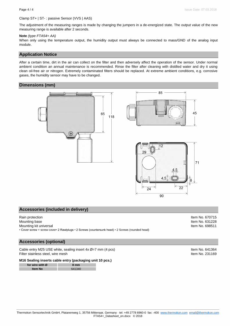
Page 4 / 4 Issue Date: 07.03.2018
Thermokon Sensortechnik GmbH, Platanenweg 1, 35756 Mittenaar, Germany · tel: +49 2778 6960-0 fax: -400 www.thermokon.com [email protected] FTA54+_Datasheet_en.docx © 2018
Clamp ST+ | ST- : passive Sensor (VVS | AAS)
The adjustment of the measuring ranges is made by changing the jumpers in a de-energized state. The output value of the new
measuring range is available after 2 seconds.
Note (type FTA54+ AA)
When only using the temperature output, the humidity output must always be connected to mass/GND of the analog input
module.
Application Notice
After a certain time, dirt in the air can collect on the filter and then adversely affect the operation of the sensor. Under normal
ambient condition an annual maintenance is recommended. Rinse the filter after cleaning with distilled water and dry it using
clean oil-free air or nitrogen. Extremely contaminated filters should be replaced. At extreme ambient conditions, e.g. corrosive
gases, the humidity sensor may have to be changed.
Dimensions (mm)
Accessories (included in delivery)
Rain protection Item No. 670715
Mounting base Item No. 631228
Mounting kit universal Item No. 698511 • Cover screw + screw cover• 2 Rawlplugs • 2 Screws (countersunk head) • 2 Screws (rounded head)
Accessories (optional)
Cable entry M25 USE white, sealing insert 4x Ø=7 mm (4 pcs) Item No. 641364
Filter stainless steel, wire mesh Item No. 231169
M16 Sealing inserts cable entry (packaging unit 10 pcs.)
for wire with Ø 8 mm
Item No 641340

Data sheet | Item number: 750-150016-channel digital output; 24 VDC; 0.5 A; Ribbon cablewww.wago.com/750-1500
22.10.2018 Page /1 12
RoHS .,¡' Compliant
BOMcheckr.net
Status _--r.!I ,l ~ Oatenkontakte 001, .. 0016 " ,"
,
24V ---
00 00 00 00 00 00 00 00 00 00
Anschlussstecker 001 ... 0016, OVund24VOC
ov

Data sheet | Item number: 750-1500www.wago.com/750-1500
22.10.2018 Page /2 12
Item description
u-
'. Status - - --f.'1 L
001 ... 00 16 :, I Datacofll3(ts
+--- Connector 001 .. . 00 16, OVand24V DC
Ir l.r
0.5 A
7 -c:::J- ' ; 00 1 2; 002 -c:::J-
3: 003 4: 004
5: 005 : r 6: COó , •• , 7: 007 , •• • 8: 00 8 9: 009 , •• • 10: DO 10
11: DO 11 , •• • 12: 00 12 • • • 00
13: 00 13 " •• " 14:0014 15: 00 15 " •• " 16:0016
" ~: " " " " ¡; ; ~ 17, 19: +24 V IB, 20:0V
24 V o V IU- )
7
, ,¡ .. , 00'
1:" : .. .. ,
I:~ • . " 00 1S I:~ • ... DO 16 oo • +24 V " " OV ,, ' " .
oo. ~
+24 V 1 <;¡ , Oy
~h
U-

Data sheet | Item number: 750-1500www.wago.com/750-1500
22.10.2018 Page /3 12
The digital output module provides sixteen channels in a width of just 12 mm (0.47 inch).
It transmits binary control signals from the automation device to connected actuators (e.g., magnetic valves, contactors, transmitters, relays or other electrical loads).
The module connects electronic modules via a 20-pole flat cable.
The 24V power is fed to the electronic modules via two CAGE CLAMP terminals.®
A green LED indicates the switched status of each channel.
Field and system levels are electrically isolated.
DataTechnical Data
Number of digital outputs 16
Total number of channels (module) 16
Type of signal Voltage
Type of signal voltage DC 24 V
Actuator connection 16 x (1-conductor)
Output characteristic high-side switching
Output current per channel 0.5 A
Output current short-circuit-protected
Switching frequency max. 1kHz
Type of load resistive, inductive, lamps
Switching frequency (max.) 1000 Hz
Max. output data width (internal) 16 Bit
Field supply voltage DC 24 V (-25 … 30 %); via wiring level (CAGE CLAMP connection)®
Current consumption, field supply (module with no external load) 29 mA
System supply voltage DC 5 V; via data contacts
Current consumption, system supply (5 V) 40 mA
Isolation field – system 500 VAC (1 min)
Indicators LED (1-16) green: Status DO 1 … DO 16
Connection data
Connection technology: inputs/outputs 20 x 20-pin male connector
Connection technology: field supply 2 x CAGE CLAMP®
Connection type (1) Inputs/Outputs
Connection type (2) Feldversorgung
Solid conductor (2) 0.08 … 2.5 mm² / 28 … 14 AWG
Fine-stranded conductor (2) 0.08 … 2.5 mm² / 28 … 14 AWG
Strip length (2) 8 … 9 mm / 0.31 … 0.35 Inch
Geometrical Data

Data sheet | Item number: 750-1500www.wago.com/750-1500
22.10.2018 Page /4 12
Geometrical Data
Width 12 mm / 0.472 inch
Height 74.1 mm / 2.917 inch
Height from upper-edge of DIN-35 rail 66.9 mm / 2.634 inch
Depth 100 mm / 3.937 inch
Mechanical data
Type of mounting DIN-35 rail
Material Data
Color lichtgrau
Housing material Polycarbonate, polyamide 6.6
Fire load 1.013 MJ
Weight 46.529 g
Conformity marking CE
Environmental Requirements
Surrounding air (operating) temperature 0 … 55 °C
Surrounding air (storage) temperature -40 … 85 °C
Degree of protection IP20
Degree of pollution (5) 2 per IEC 61131-2
Operating altitude 0 … 2000 m
Mounting position horizontal (standing/lying) or vertical
Relative air humidity (no condensation) 95 %
Vibration resistance 4g per IEC 60068-2-6
Shock resistance 15g per IEC 60068-2-27
EMC immunity to interference acc. to EN 61000-6-2, marine applications
EMC emission of interference acc. to EN 61000-6-3, marine applications
Exposure to pollutants Per IEC 60068-2-42 and IEC 60068-2-43
Permissible H S contaminant concentration at a relative humidity < 2
75 %
10 ppm
Permissible SO contaminant concentration at a relative humidity < 2
75 %
25 ppm
Commercial data
Country of rigin DE
GTIN 4045454898267
Customs Tariff No. 85371098990
Product Group 15 (Remote I/O)

Data sheet | Item number: 750-1500www.wago.com/750-1500
22.10.2018 Page /5 12
Approvals / Certificates
Ex-Approvals
Logo Approval Certificate name
ATEXTUEV Nord Cert GmbH
TÜV 07 ATEX 554086 X en.
TUEV NordTUEV Nord Cert GmbH
IECEx TUN 09.0001 X
ULUnderwriters Laboratories Inc. (HAZARDOUS LOCATIONS)
E198726 Sec.1 (HAZARDOUS LOCATIONS)
Ship Approvals
Logo Approval Certificate name
ABSAmerican Bureau of Shipping
16-HG1554285-PDA
BVBureau Veritas S.A.
30389/B0 BV
DNVDNV Germany GmbH
A-14093
GLGermanischer Lloyd
11 631 - 10 HH
LR{Lloyds Register EMEA
02/20026 (E5)
NKNippon Kaiji Kyokai
TA17255M
PRSPolski Rejetr Statkow
TE/1989/880590/13
RINARINA Germany GmbH
ELE134212XG

Data sheet | Item number: 750-1500www.wago.com/750-1500
22.10.2018 Page /6 12
UL-Approvals
Logo Approval Certificate name
ULUL International Netherlands B.V. (ORDINARY LOCATIONS)
E175199 Sec.1 (ORDINARY LOCATIONS)
Compatible productssystem box
Item no.: 850-804IP65 enclosure; Stainless steel; WxHxD (400x123x200 mm); 4 x M20, 16 x M16, 28 x M12 cable grip www.wago.com/850-804
Item no.: 850-804/000-001IP65 enclosure; Stainless steel; WxHxD (400x123x200 mm); 2 x M20, 13 x M16, 32 x M12 cable grip
www.wago.com/850-804/000-001
Item no.: 850-805IP65 enclosure; Stainless steel; WxHxD (600x123x200 mm); 4 x M20, 19 x M16, 67 x M12 cable grip www.wago.com/850-805
Item no.: 850-814/002-000IP65 enclosure; Sheet steel (RAL 7035); WxHxD (200x120x200 mm); without flange plate
www.wago.com/850-814/002-000
Item no.: 850-815/002-000IP65 enclosure; Sheet steel (RAL 7035); WxHxD (300x120x200 mm); without flange plate
www.wago.com/850-815/002-000
Item no.: 850-816/002-000IP65 enclosure; Sheet steel (RAL 7035); WxHxD (400x120x200 mm); without flange plate
www.wago.com/850-816/002-000
Item no.: 850-817/002-000IP65 enclosure; Sheet steel (RAL 7035); WxHxD (600x120x200 mm); without flange plate
www.wago.com/850-817/002-000
Item no.: 850-825IP65 enclosure; Aluminium (RAL 7032); WxHxD (160x100x160 mm); 9 x M12, 4 x M20 www.wago.com/850-825
Item no.: 850-826IP65 enclosure; Aluminium (RAL 7032); WxHxD (240x100x160 mm); 4 x M20, 4 x M16, 14 x M12 cable grip
www.wago.com/850-826
Item no.: 850-826/002-000IP65 enclosure; Aluminium (RAL 7035); WxHxD (240x100x160 mm); 4 x M20, 4 x M16, 14 x M12 cable grip
www.wago.com/850-826/002-000
Item no.: 850-827IP65 enclosure; Aluminium (RAL 7032); WxHxD (320x100x160 mm); 4 x M20, 8 x M16, 17 x M12 cable grip
www.wago.com/850-827
Item no.: 850-827/002-000 www.wago.com/850-827

Data sheet | Item number: 750-1500www.wago.com/750-1500
22.10.2018 Page /7 12
Item no.: 850-827/002-000IP65 enclosure; Aluminium (RAL 7035); WxHxD (320x100x160 mm); 4 x M20, 8 x M16, 17 x M12 cable grip
www.wago.com/850-827/002-000
Item no.: 850-828IP65 enclosure; Aluminium (RAL 7032); WxHxD (480x100x160 mm); 4 x M20, 10 x M16, 35 x M12 cable grip
www.wago.com/850-828
Item no.: 850-828/002-000IP65 enclosure; Aluminium (RAL 7035); WxHxD (480x100x160 mm); 4 x M20, 10 x M16, 35 x M12 cable grip
www.wago.com/850-828/002-000
Item no.: 850-834IP65 enclosure; Polyester (RAL 7032); WxHxD (164x100x164 mm); 9 x M12, 4 x M20 www.wago.com/850-834
Item no.: 850-835IP65 enclosure; Polyester (RAL 7032); WxHxD (244x100x164 mm); 4 x M20, 4 x M16, 14 x M12 cable grip
www.wago.com/850-835
Item no.: 850-836IP65 enclosure; Polyester (RAL 7032); WxHxD (324x100x164 mm); 4 x M20, 8 x M16, 17 x M12 cable grip
www.wago.com/850-836
shield connection
Item no.: 790-108Shield clamping saddle; 11 mm wide; diameter of compatible conductor www.wago.com/790-108
Item no.: 790-116Shield clamping saddle; 19 mm wide; diameter of compatible conductor; 7 ... 16 mm www.wago.com/790-116
Item no.: 790-124Shield clamping saddle; 27 mm wide; diameter of compatible conductor; 6 mm to 24 mm www.wago.com/790-124
Item no.: 790-140Shield clamping saddle; 43 mm wide; diameter of compatible conductor; 22 mm to 40 mm www.wago.com/790-140
Item no.: 790-208Shield clamping saddle; 12.4 mm wide; 3 ... 8 mm www.wago.com/790-208
Item no.: 790-216Shield clamping saddle; 6–16 mm diameter; 21.8 mm wide www.wago.com/790-216
Item no.: 790-220Shield clamping saddle; 6–20 mm diameter; 30 mm wide www.wago.com/790-220
Marking accessories
Item no.: 2009-145Mini-WSB Inline; for smartPRINTER; on reel; stretchable 5 - 5.2 mm; plain; snap-on type www.wago.com/2009-145
Item no.: 2009-145/000-002Mini-WSB Inline; for smartPRINTER; on reel; stretchable 5 - 5.2 mm; plain; snap-on type
www.wago.com/2009-145/000-002
Item no.: 2009-145/000-005Mini-WSB Inline; for smartPRINTER; on reel; stretchable 5 - 5.2 mm; plain; snap-on type
www.wago.com/2009-145/000-005
Item no.: 2009-145/000-006

Data sheet | Item number: 750-1500www.wago.com/750-1500
22.10.2018 Page /8 12
Item no.: 2009-145/000-006Mini-WSB Inline; for smartPRINTER; on reel; stretchable 5 - 5.2 mm; plain; snap-on type www.wago.com/2009-145
/000-006
Item no.: 2009-145/000-007Mini-WSB Inline; plain; 1,700 Mini-WSB markers (5 mm) on roll; stretchable 5 - 5.2 mm
www.wago.com/2009-145/000-007
Item no.: 2009-145/000-012Mini-WSB Inline; for smartPRINTER; on reel; stretchable 5 - 5.2 mm; plain; snap-on type
www.wago.com/2009-145/000-012
Item no.: 2009-145/000-023Mini-WSB Inline; on reel; stretchable 5 - 5.2 mm; plain; snap-on type
www.wago.com/2009-145/000-023
Item no.: 2009-145/000-024Mini-WSB Inline; on reel; stretchable 5 - 5.2 mm; plain; snap-on type
www.wago.com/2009-145/000-024
Item no.: 248-501Miniature WSB Quick marking system; plain; Marker width 5 mm; 10 strips with 10 markers per card www.wago.com/248-501
Item no.: 248-501/000-002Mini-WSB marking card; as card; not stretchable; plain; snap-on type
www.wago.com/248-501/000-002
Item no.: 248-501/000-005Mini-WSB marking card; as card; plain; snap-on type
www.wago.com/248-501/000-005
Item no.: 248-501/000-006Mini-WSB marking card; as card; not stretchable; plain; snap-on type
www.wago.com/248-501/000-006
Item no.: 248-501/000-007Mini-WSB marking card; as card; not stretchable; plain; snap-on type
www.wago.com/248-501/000-007
Item no.: 248-501/000-012Mini-WSB marking card; as card; not stretchable; plain; snap-on type
www.wago.com/248-501/000-012
Item no.: 248-501/000-017Mini-WSB marking card; as card; not stretchable; plain; snap-on type
www.wago.com/248-501/000-017
Item no.: 248-501/000-023Mini-WSB marking card; as card; not stretchable; plain; snap-on type
www.wago.com/248-501/000-023
Item no.: 248-501/000-024Mini-WSB marking card; as card; not stretchable; plain; snap-on type
www.wago.com/248-501/000-024
Item no.: 750-103Group marker carrier www.wago.com/750-103
Item no.: 750-107 www.wago.com/750-107

Data sheet | Item number: 750-1500www.wago.com/750-1500
22.10.2018 Page /9 12
Item no.: 750-107Group marker carrier
www.wago.com/750-107
transfer module Item no.: 704-5003
Interface module for system wiring; Pluggable connector per DIN 41651; Male connector; 10-pole; 8-channel relay output; 1 changeover contact; 1 x cut-out; Triple-deck PCB terminal blocks; in mounting carrier
www.wago.com/704-5003
Item no.: 704-5004Interface module for system wiring; Pluggable connector per DIN 41651; Male connector; 20-pole; 16-channel relay output; 1 changeover contact; 1 x cut-out; Double-deck PCB terminal blocks; in mounting carrier
www.wago.com/704-5004
Item no.: 704-5013Interface module for system wiring; Pluggable connector per DIN 41651; Male connector; 10-pole; 8-channel relay output; 1 changeover contact; 1 x cut-out; Triple-deck PCB terminal blocks; with manual operation; in mounting carrier
www.wago.com/704-5013
Item no.: 704-5014Interface module for system wiring; Pluggable connector per DIN 41651; Male connector; 20-pole; 16-channel relay output; 1 changeover contact; 1 x cut-out; Double-deck PCB terminal blocks; without relay; in mounting carrier
www.wago.com/704-5014
Item no.: 704-5024Interface module for system wiring; Pluggable connector per DIN 41651; Male connector; 20-pole; 16-channel relay output; 1 changeover contact; 1 x cut-out; Triple-deck PCB terminal blocks; in mounting carrier
www.wago.com/704-5024
Item no.: 704-5034Interface module for system wiring; Pluggable connector per DIN 41651; Male connector; 20-pole; 16-channel relay output; 1 changeover contact; 1 x cut-out; PCB terminal blocks; with output fuse; in mounting carrier
www.wago.com/704-5034
Item no.: 704-5044Interface module for system wiring; Pluggable connector per DIN 41651; Male connector; 20-pole; 16-channel relay output; 1 changeover contact; 1 x cut-out; Triple-deck PCB terminal blocks; with manual operation; in mounting carrier
www.wago.com/704-5044
Item no.: 704-5054Interface module for system wiring; Pluggable connector per DIN 41651; Male connector; 20-pole; 16-channel relay output; 1 changeover contact; 1 x cut-out; PCB disconnect terminal blocks; with output fuse; in mounting carrier
www.wago.com/704-5054
Item no.: 704-5064Interface module for system wiring; Pluggable connector per DIN 41651; Male connector; 20-pole; 16-channel relay output; 2 changeover contacts; Double-deck PCB terminal blocks; in mounting carrier
www.wago.com/704-5064
Item no.: 704-5074Interface module for system wiring; Pluggable connector per DIN 41651; Male connector; 20-pole; 16-channel relay output; 1 changeover contact; 1 x cut-out; PCB disconnect terminal blocks; with output fuse; in mounting carrier
www.wago.com/704-5074
Item no.: 857-981Interface adapter; 14-pole; High-side switching input www.wago.com/857-981
Item no.: 857-982Interface adapter; 14-pole; High-side switching output www.wago.com/857-982
Carrier rail
Item no.: 210-112 www.wago.com/210-112

Data sheet | Item number: 750-1500www.wago.com/750-1500
22.10.2018 Page /10 12
Item no.: 210-112Steel carrier rail; 35 x 7.5 mm; 1 mm thick; 2 m long; slotted; according to EN 60715; "Hole width 25 mm
www.wago.com/210-112
Item no.: 210-113Steel carrier rail; 35 x 7.5 mm; 1 mm thick; 2 m long; unslotted; according to EN 60715 www.wago.com/210-113
Item no.: 210-114Steel carrier rail; 35 x 15 mm; 1.5 mm thick; 2 m long; unslotted; similar to EN 60715 www.wago.com/210-114
Item no.: 210-115Steel carrier rail; 35 x 7.5 mm; 1 mm thick; 2 m long; slotted; according to EN 60715; "Hole width 18 mm www.wago.com/210-115
Item no.: 210-118Steel carrier rail; 35 x 15 mm; 2.3 mm thick; 2 m long; unslotted; according to EN 60715 www.wago.com/210-118
Item no.: 210-196Aluminum carrier rail; 35 x 8.2 mm; 1.6 mm thick; 2 m long; unslotted; similar to EN 60715 www.wago.com/210-196
Item no.: 210-197Steel carrier rail; 35 x 15 mm; 1.5 mm thick; 2 m long; slotted; similar to EN 60715 www.wago.com/210-197
Item no.: 210-198Copper carrier rail; 35 x 15 mm; 2.3 mm thick; 2 m long; unslotted; according to EN 60715 www.wago.com/210-198
Item no.: 210-504Steel carrier rail; 35 x 7.5 mm; 1 mm thick; 2 m long; slotted; galvanized; according to EN 60715 www.wago.com/210-504
Item no.: 210-505Steel carrier rail; 35 x 7.5 mm; 1 mm thick; 2 m long; unslotted; galvanized; according to EN 60715 www.wago.com/210-505
Item no.: 210-506Steel carrier rail; 35 x 15 mm; 1.5 mm thick; 2 m long; unslotted; galvanized; similar to EN 60715 www.wago.com/210-506
Item no.: 210-508Steel carrier rail; 35 x 15 mm; 1.5 mm thick; 2 m long; slotted; galvanized; similar to EN 60715 www.wago.com/210-508
wiring and connectors
Item no.: 706-3057/300-100System cable; for Schneider TSX; 16 digital inputs or outputs; Length: 1 m (1 MOhm); Conductor cross-section: 0.14 mm²
www.wago.com/706-3057/300-100
Item no.: 706-3057/300-200System cable; for Schneider TSX; 16 digital inputs or outputs; Length: 2 m; Conductor cross-section: 0.14 mm²
www.wago.com/706-3057/300-200
Item no.: 706-3057/300-300System cable; for Schneider TSX; 16 digital inputs or outputs; Length: 3 m; Conductor cross-section: 0.14 mm²
www.wago.com/706-3057/300-300
Item no.: 706-7753/302-100System cable; for WAGO-I/O-SYSTEM, 753 Series; 8 digital inputs and 8 digital outputs; Length: 1 m (1 MOhm); Conductor cross-section: 0.14 mm²
www.wago.com/706-7753/302-100
Item no.: 706-7753/302-200System cable; for WAGO-I/O-SYSTEM, 753 Series; 8 digital inputs and 8 digital outputs; Length: 2 m; Conductor cross-section: 0.14 mm²
www.wago.com/706-7753/302-200
Item no.: 706-7753/304-100
System cable; for WAGO-I/O-SYSTEM, 750 Series; 2 x 8 analog inputs or outputs; Length: 1 m (1 www.wago.com/706-7753

Data sheet | Item number: 750-1500www.wago.com/750-1500
22.10.2018 Page /11 12
System cable; for WAGO-I/O-SYSTEM, 750 Series; 2 x 8 analog inputs or outputs; Length: 1 m (1 MOhm); Conductor cross-section: 0.14 mm²
www.wago.com/706-7753/304-100
Item no.: 706-7753/304-200System cable; for WAGO-I/O-SYSTEM, 750 Series; 2 x 8 analog inputs or outputs; Length: 2 m; Conductor cross-section: 0.14 mm²
www.wago.com/706-7753/304-200
Item no.: 706-7753/304-300System cable; for WAGO-I/O-SYSTEM, 750 Series; 2 x 8 analog inputs or outputs; Length: 3 m; Conductor cross-section: 0.14 mm²
www.wago.com/706-7753/304-300
DownloadsDocumentation
Manual
16-channel, 24VDCFlat cable, high-side switching
03-feb-20152.3 MB
Download
Bid Text
750-1500IO-Klemmen
20-ene-2016 DOC27.6 kB
Download
System Description
Use in Hazardous EnvironmentsTerm definition, marking and installation regulations
08-may-20141.0 MB
Download
750/753 Series I/O-System ‒ General Product Information 29-may-20182.0 MB
Download
Overview on WAGO-I/O-SYSTEM 750 approvals 06-jun-2017314.9 kB
Download
Design NotesBasic conditions and recommendations for higher operational safety
03-may-20111.5 MB
Download
smartDATA
CAD data
3D Download 750-1500 URL Download
Device Files
Device Driver
WAGO USB Service Cable Driver / 750 and 857 Series 6.5.3.0 ZIP Download

Data sheet | Item number: 750-1500www.wago.com/750-1500
22.10.2018 Page /12 12
Subject to changes.
WAGO Kontakttechnik GmbH & Co. KG Hansastr. 27 32423 Minden Phone: +49571 887-0 | Fax: +49571 887-169 Email: [email protected] | Web: www.wago.com
Do you have any questions about our products? We are always happy to take your call at +49 (571) 887-44222.
WAGO USB Service Cable Driver / 750 and 857 Series 6.5.3.010-sep-2014
ZIP4.8 MB
Download
Product family
750/753 Series I/O-SystemShow all products from the family.

Data sheet | Item number: 750-140016-channel digital input; 24 VDC; 3 ms; Ribbon cablewww.wago.com/750-1400
22.10.2018 Page /1 11
RoHS .,¡' Compliant
'"
BOMcheckr.net
~
Status .. . 0116
24V
~
1>0-"'"
1!ll!4
Ir: ~ '''''''".k'' ' o O . ' 00 .
f:I I O
' " 0 0 " , 0 0 1
D O '
q= 1 1 ~c
00 00 00
" r--- Anschlussstecker 00 00 011 ... 01 16, 00 OVund24VDC 00 ,
L;..:'
~
H DV
U

Data sheet | Item number: 750-1400www.wago.com/750-1400
22.10.2018 Page /2 11
Item description
Ir ' ><>-''''''lr l iITi ~
, '11ll' ' 00 •
Status ' O D . , DO •
011 ",0116 • DO ,
" °gl,'; DO ' DO '
¡E , ~
0 0 0 0 00 00 00 00 0 0 00 , V; /¡;:
24V -1 ~ UL
Ir l.r @ 3 m. 7
U+-- 1: 011 3:013
5:015 : r , •• , 7:017 , •• • 9: 019 , •• •
1I: 0111 , • • • • • • " 13: 0113 " •• "
15:0115 " •• " " ~ :
.. " " " ¡; ; ~
17, 19, 24V
24 y (U-) " "
!!J -uc
~ "~"'""'.
Connector 011 ... 011 6, OVand24VDC
OV
2:01' -"- U+ 4:014
6: 016 8: 018 10:0110 12:01 12 14:01 14
16:0116-
IB, 20:0V
Q Y
'"
0116 OV
,.
",,' " . ,~,

Data sheet | Item number: 750-1400www.wago.com/750-1400
22.10.2018 Page /3 11
The digital input module provides sixteen channels in a width of just 12 mm (0.47 inch).
It receives binary control signals from digital field devices (e.g., sensors, encoders, switches or proximity switches).
The module connects electronic modules via a 20-pole flat cable.
The 24V power is fed to the electronic modules via two CAGE CLAMP terminals.®
Each input channel has a noise-rejection RC filter with 3.0 ms time constant.
A green LED indicates the switched status of each channel.
Field and system levels are electrically isolated.
DataTechnical Data
Number of digital inputs 16
Total number of channels (module) 16
Type of signal Voltage
Type of signal voltage DC 24 V
Sensor supply voltage 24 V DC
Sensor connection 16 x (1-conductor)
Input characteristic high-side switching
Input filter (digital) 3 ms
Input current per channel for signal (0) typ. 0.6 mA
Input current per channel for signal (1) min. 2.1 mA
Input current per channel for signal (1) max. 2.4 mA
Voltage range for signal (0) −3 … +5 VDC
Voltage range for signal (1) 15 … 30 VDC
Max. input data width (internal) 16 Bit
Field supply voltage DC 24 V (-25 … 30 %); via wiring level (CAGE CLAMP connection)®
System supply voltage DC 5 V; via data contacts
Current consumption, system supply (5 V) 25 mA
Isolation field – system 500 VAC (1 min)
Indicators LED (1-16) green: Status DI 1 … DI 16
Connection data
Connection technology: inputs/outputs 20 x 20-pin male connector
Connection technology: field supply 2 x CAGE CLAMP®
Connection type (1) Inputs/Outputs
Connection type (2) Feldversorgung
Solid conductor (2) 0.08 … 2.5 mm² / 28 … 14 AWG
Fine-stranded conductor (2) 0.08 … 2.5 mm² / 28 … 14 AWG
Strip length (2) 8 … 9 mm / 0.31 … 0.35 Inch

Data sheet | Item number: 750-1400www.wago.com/750-1400
22.10.2018 Page /4 11
Strip length (2) 8 … 9 mm / 0.31 … 0.35 Inch
Geometrical Data
Width 12 mm / 0.472 inch
Height 74.1 mm / 2.917 inch
Height from upper-edge of DIN-35 rail 66.9 mm / 2.634 inch
Depth 100 mm / 3.937 inch
Mechanical data
Type of mounting DIN-35 rail
Material Data
Color lichtgrau
Housing material Polycarbonate, polyamide 6.6
Fire load 1.057 MJ
Weight 41.729 g
Conformity marking CE
Environmental Requirements
Surrounding air (operating) temperature 0 … 55 °C
Surrounding air (storage) temperature -40 … 85 °C
Degree of protection IP20
Degree of pollution (5) 2 per IEC 61131-2
Operating altitude 0 … 2000 m
Mounting position horizontal (standing/lying) or vertical
Relative air humidity (no condensation) 95 %
Vibration resistance 4g per IEC 60068-2-6
Shock resistance 15g per IEC 60068-2-27
EMC immunity to interference acc. to EN 61000-6-2, marine applications
EMC emission of interference acc. to EN 61000-6-3, marine applications
Exposure to pollutants Per IEC 60068-2-42 and IEC 60068-2-43
Permissible H S contaminant concentration at a relative humidity < 2
75 %
10 ppm
Permissible SO contaminant concentration at a relative humidity < 2
75 %
25 ppm
Commercial data
Country of rigin DE
GTIN 4045454880590
Customs Tariff No. 85389099990

Data sheet | Item number: 750-1400www.wago.com/750-1400
22.10.2018 Page /5 11
Customs Tariff No. 85389099990
Product Group 15 (Remote I/O)
Approvals / Certificates
Ex-Approvals
Logo Approval Certificate name
ATEXTUEV Nord Cert GmbH
TÜV 07 ATEX 554086 X en.
TUEV NordTUEV Nord Cert GmbH
IECEx TUN 09.0001 X
ULUnderwriters Laboratories Inc. (HAZARDOUS LOCATIONS)
E198726 Sec.1 (HAZARDOUS LOCATIONS)
Ship Approvals
Logo Approval Certificate name
ABSAmerican Bureau of Shipping
16-HG1554285-PDA
BVBureau Veritas S.A.
30389/B0 BV
DNVDNV Germany GmbH
A-14093
GLGermanischer Lloyd
11 631 - 10 HH
LR{Lloyds Register EMEA
02/20026 (E5)
NKNippon Kaiji Kyokai
TA17255M
PRSPolski Rejetr Statkow
TE/1989/880590/13
RINA ELE134212XG

Data sheet | Item number: 750-1400www.wago.com/750-1400
22.10.2018 Page /6 11
RINARINA Germany GmbH
ELE134212XG
UL-Approvals
Logo Approval Certificate name
ULUL International Netherlands B.V. (ORDINARY LOCATIONS)
E175199 Sec.1 (ORDINARY LOCATIONS)
Compatible productswiring and connectors
Item no.: 706-3057/300-100System cable; for Schneider TSX; 16 digital inputs or outputs; Length: 1 m (1 MOhm); Conductor cross-section: 0.14 mm²
www.wago.com/706-3057/300-100
Item no.: 706-3057/300-200System cable; for Schneider TSX; 16 digital inputs or outputs; Length: 2 m; Conductor cross-section: 0.14 mm²
www.wago.com/706-3057/300-200
Item no.: 706-3057/300-300System cable; for Schneider TSX; 16 digital inputs or outputs; Length: 3 m; Conductor cross-section: 0.14 mm²
www.wago.com/706-3057/300-300
Item no.: 706-7753/302-100System cable; for WAGO-I/O-SYSTEM, 753 Series; 8 digital inputs and 8 digital outputs; Length: 1 m (1 MOhm); Conductor cross-section: 0.14 mm²
www.wago.com/706-7753/302-100
Item no.: 706-7753/302-200System cable; for WAGO-I/O-SYSTEM, 753 Series; 8 digital inputs and 8 digital outputs; Length: 2 m; Conductor cross-section: 0.14 mm²
www.wago.com/706-7753/302-200
system box
Item no.: 850-804IP65 enclosure; Stainless steel; WxHxD (400x123x200 mm); 4 x M20, 16 x M16, 28 x M12 cable grip www.wago.com/850-804
Item no.: 850-804/000-001IP65 enclosure; Stainless steel; WxHxD (400x123x200 mm); 2 x M20, 13 x M16, 32 x M12 cable grip
www.wago.com/850-804/000-001
Item no.: 850-805IP65 enclosure; Stainless steel; WxHxD (600x123x200 mm); 4 x M20, 19 x M16, 67 x M12 cable grip www.wago.com/850-805
Item no.: 850-814/002-000IP65 enclosure; Sheet steel (RAL 7035); WxHxD (200x120x200 mm); without flange plate
www.wago.com/850-814/002-000
Item no.: 850-815/002-000IP65 enclosure; Sheet steel (RAL 7035); WxHxD (300x120x200 mm); without flange plate
www.wago.com/850-815/002-000

Data sheet | Item number: 750-1400www.wago.com/750-1400
22.10.2018 Page /7 11
Item no.: 850-816/002-000IP65 enclosure; Sheet steel (RAL 7035); WxHxD (400x120x200 mm); without flange plate
www.wago.com/850-816/002-000
Item no.: 850-817/002-000IP65 enclosure; Sheet steel (RAL 7035); WxHxD (600x120x200 mm); without flange plate
www.wago.com/850-817/002-000
Item no.: 850-825IP65 enclosure; Aluminium (RAL 7032); WxHxD (160x100x160 mm); 9 x M12, 4 x M20 www.wago.com/850-825
Item no.: 850-826IP65 enclosure; Aluminium (RAL 7032); WxHxD (240x100x160 mm); 4 x M20, 4 x M16, 14 x M12 cable grip
www.wago.com/850-826
Item no.: 850-826/002-000IP65 enclosure; Aluminium (RAL 7035); WxHxD (240x100x160 mm); 4 x M20, 4 x M16, 14 x M12 cable grip
www.wago.com/850-826/002-000
Item no.: 850-827IP65 enclosure; Aluminium (RAL 7032); WxHxD (320x100x160 mm); 4 x M20, 8 x M16, 17 x M12 cable grip
www.wago.com/850-827
Item no.: 850-827/002-000IP65 enclosure; Aluminium (RAL 7035); WxHxD (320x100x160 mm); 4 x M20, 8 x M16, 17 x M12 cable grip
www.wago.com/850-827/002-000
Item no.: 850-828IP65 enclosure; Aluminium (RAL 7032); WxHxD (480x100x160 mm); 4 x M20, 10 x M16, 35 x M12 cable grip
www.wago.com/850-828
Item no.: 850-828/002-000IP65 enclosure; Aluminium (RAL 7035); WxHxD (480x100x160 mm); 4 x M20, 10 x M16, 35 x M12 cable grip
www.wago.com/850-828/002-000
Item no.: 850-834IP65 enclosure; Polyester (RAL 7032); WxHxD (164x100x164 mm); 9 x M12, 4 x M20 www.wago.com/850-834
Item no.: 850-835IP65 enclosure; Polyester (RAL 7032); WxHxD (244x100x164 mm); 4 x M20, 4 x M16, 14 x M12 cable grip
www.wago.com/850-835
Item no.: 850-836IP65 enclosure; Polyester (RAL 7032); WxHxD (324x100x164 mm); 4 x M20, 8 x M16, 17 x M12 cable grip
www.wago.com/850-836
Carrier rail
Item no.: 210-112Steel carrier rail; 35 x 7.5 mm; 1 mm thick; 2 m long; slotted; according to EN 60715; "Hole width 25 mm www.wago.com/210-112
Item no.: 210-113Steel carrier rail; 35 x 7.5 mm; 1 mm thick; 2 m long; unslotted; according to EN 60715 www.wago.com/210-113
Item no.: 210-114Steel carrier rail; 35 x 15 mm; 1.5 mm thick; 2 m long; unslotted; similar to EN 60715 www.wago.com/210-114
Item no.: 210-115Steel carrier rail; 35 x 7.5 mm; 1 mm thick; 2 m long; slotted; according to EN 60715; "Hole width 18 mm www.wago.com/210-115
Item no.: 210-118 www.wago.com/210-118

Data sheet | Item number: 750-1400www.wago.com/750-1400
22.10.2018 Page /8 11
Item no.: 210-118Steel carrier rail; 35 x 15 mm; 2.3 mm thick; 2 m long; unslotted; according to EN 60715
www.wago.com/210-118
Item no.: 210-196Aluminum carrier rail; 35 x 8.2 mm; 1.6 mm thick; 2 m long; unslotted; similar to EN 60715 www.wago.com/210-196
Item no.: 210-197Steel carrier rail; 35 x 15 mm; 1.5 mm thick; 2 m long; slotted; similar to EN 60715 www.wago.com/210-197
Item no.: 210-198Copper carrier rail; 35 x 15 mm; 2.3 mm thick; 2 m long; unslotted; according to EN 60715 www.wago.com/210-198
Item no.: 210-504Steel carrier rail; 35 x 7.5 mm; 1 mm thick; 2 m long; slotted; galvanized; according to EN 60715 www.wago.com/210-504
Item no.: 210-505Steel carrier rail; 35 x 7.5 mm; 1 mm thick; 2 m long; unslotted; galvanized; according to EN 60715 www.wago.com/210-505
Item no.: 210-506Steel carrier rail; 35 x 15 mm; 1.5 mm thick; 2 m long; unslotted; galvanized; similar to EN 60715 www.wago.com/210-506
Item no.: 210-508Steel carrier rail; 35 x 15 mm; 1.5 mm thick; 2 m long; slotted; galvanized; similar to EN 60715 www.wago.com/210-508
shield connection
Item no.: 790-108Shield clamping saddle; 11 mm wide; diameter of compatible conductor www.wago.com/790-108
Item no.: 790-116Shield clamping saddle; 19 mm wide; diameter of compatible conductor; 7 ... 16 mm www.wago.com/790-116
Item no.: 790-124Shield clamping saddle; 27 mm wide; diameter of compatible conductor; 6 mm to 24 mm www.wago.com/790-124
Item no.: 790-140Shield clamping saddle; 43 mm wide; diameter of compatible conductor; 22 mm to 40 mm www.wago.com/790-140
Item no.: 790-208Shield clamping saddle; 12.4 mm wide; 3 ... 8 mm www.wago.com/790-208
Item no.: 790-216Shield clamping saddle; 6–16 mm diameter; 21.8 mm wide www.wago.com/790-216
Item no.: 790-220Shield clamping saddle; 6–20 mm diameter; 30 mm wide www.wago.com/790-220
transfer module
Item no.: 289-611Interface module; for flat cable connectors per DIN 41651; 10-pole www.wago.com/289-611
Item no.: 289-614Interface module; for flat cable connectors per DIN 41651; 20-pole www.wago.com/289-614
Item no.: 704-2003Interface module for system wiring; Pluggable connector per DIN 41651; Male connector; 10-pole; 8-channel digital input or output; 3-wire connection; Triple-deck PCB terminal blocks; in mounting carrier
www.wago.com/704-2003
Item no.: 704-2004
Interface module for system wiring; Pluggable connector per DIN 41651; Male connector; 20-pole; 16- www.wago.com/704-2004

Data sheet | Item number: 750-1400www.wago.com/750-1400
22.10.2018 Page /9 11
Interface module for system wiring; Pluggable connector per DIN 41651; Male connector; 20-pole; 16-channel digital input or output; 1-wire connection; Double-deck PCB terminal blocks; in mounting carrier
www.wago.com/704-2004
Item no.: 704-2024Interface module for system wiring; Pluggable connector per DIN 41651; Male connector; 20-pole; 16-channel digital input or output; 2-wire connection; Double-deck PCB terminal blocks; in mounting carrier
www.wago.com/704-2024
Item no.: 704-2044Interface module for system wiring; Pluggable connector per DIN 41651; Male connector; 20-pole; 16-channel digital input or output; 2-wire connection; PCB disconnect terminal blocks; in mounting carrier
www.wago.com/704-2044
Item no.: 704-2054Interface module for system wiring; Pluggable connector per DIN 41651; Male connector; 20-pole; 16-channel digital input or output; 3-wire connection; Triple-deck PCB terminal blocks; in mounting carrier
www.wago.com/704-2054
Item no.: 857-982Interface adapter; 14-pole; High-side switching output www.wago.com/857-982
Marking accessories
Item no.: 2009-145Mini-WSB Inline; for smartPRINTER; on reel; stretchable 5 - 5.2 mm; plain; snap-on type www.wago.com/2009-145
Item no.: 2009-145/000-002Mini-WSB Inline; for smartPRINTER; on reel; stretchable 5 - 5.2 mm; plain; snap-on type
www.wago.com/2009-145/000-002
Item no.: 2009-145/000-005Mini-WSB Inline; for smartPRINTER; on reel; stretchable 5 - 5.2 mm; plain; snap-on type
www.wago.com/2009-145/000-005
Item no.: 2009-145/000-006Mini-WSB Inline; for smartPRINTER; on reel; stretchable 5 - 5.2 mm; plain; snap-on type
www.wago.com/2009-145/000-006
Item no.: 2009-145/000-007Mini-WSB Inline; plain; 1,700 Mini-WSB markers (5 mm) on roll; stretchable 5 - 5.2 mm
www.wago.com/2009-145/000-007
Item no.: 2009-145/000-012Mini-WSB Inline; for smartPRINTER; on reel; stretchable 5 - 5.2 mm; plain; snap-on type
www.wago.com/2009-145/000-012
Item no.: 2009-145/000-023Mini-WSB Inline; on reel; stretchable 5 - 5.2 mm; plain; snap-on type
www.wago.com/2009-145/000-023
Item no.: 2009-145/000-024Mini-WSB Inline; on reel; stretchable 5 - 5.2 mm; plain; snap-on type
www.wago.com/2009-145/000-024
Item no.: 248-501Miniature WSB Quick marking system; plain; Marker width 5 mm; 10 strips with 10 markers per card www.wago.com/248-501
Item no.: 248-501/000-002Mini-WSB marking card; as card; not stretchable; plain; snap-on type
www.wago.com/248-501/000-002
Item no.: 248-501/000-005 www.wago.com/248-501

Data sheet | Item number: 750-1400www.wago.com/750-1400
22.10.2018 Page /10 11
Item no.: 248-501/000-005Mini-WSB marking card; as card; plain; snap-on type
www.wago.com/248-501/000-005
Item no.: 248-501/000-006Mini-WSB marking card; as card; not stretchable; plain; snap-on type
www.wago.com/248-501/000-006
Item no.: 248-501/000-007Mini-WSB marking card; as card; not stretchable; plain; snap-on type
www.wago.com/248-501/000-007
Item no.: 248-501/000-012Mini-WSB marking card; as card; not stretchable; plain; snap-on type
www.wago.com/248-501/000-012
Item no.: 248-501/000-017Mini-WSB marking card; as card; not stretchable; plain; snap-on type
www.wago.com/248-501/000-017
Item no.: 248-501/000-023Mini-WSB marking card; as card; not stretchable; plain; snap-on type
www.wago.com/248-501/000-023
Item no.: 248-501/000-024Mini-WSB marking card; as card; not stretchable; plain; snap-on type
www.wago.com/248-501/000-024
Item no.: 750-103Group marker carrier www.wago.com/750-103
Item no.: 750-107Group marker carrier www.wago.com/750-107
DownloadsDocumentation
Manual
16-channel, 24VDCFlat cable, high-side switching
04-feb-20162.3 MB
Download
Bid Text
750-1400IO-Klemmen
20-ene-2016 DOC27.6 kB
Download
System Description
Use in Hazardous EnvironmentsTerm definition, marking and installation regulations
08-may-20141.0 MB
Download
750/753 Series I/O-System ‒ General Product Information 29-may-20182.0 MB
Download

Data sheet | Item number: 750-1400www.wago.com/750-1400
22.10.2018 Page /11 11
Subject to changes.
WAGO Kontakttechnik GmbH & Co. KG Hansastr. 27 32423 Minden Phone: +49571 887-0 | Fax: +49571 887-169 Email: [email protected] | Web: www.wago.com
Do you have any questions about our products? We are always happy to take your call at +49 (571) 887-44222.
Overview on WAGO-I/O-SYSTEM 750 approvals 06-jun-2017314.9 kB
Download
Design NotesBasic conditions and recommendations for higher operational safety
03-may-20111.5 MB
Download
smartDATA
CAD data
3D Download 750-1400 URL Download
Device Files
Device Driver
WAGO USB Service Cable Driver / 750 and 857 Series 6.5.3.010-sep-2014
ZIP4.8 MB
Download
Product family
750/753 Series I/O-SystemShow all products from the family.

Data sheet | Item number: 750-602Power Supply; 24 VDCwww.wago.com/750-602
22.10.2018 Page /1 9
RoHS .,¡' Compliant
BOMcheclv.net
Status dar Betriebsspannung
~H-- -Laislungskonlokte
Oatenkonlakle
Versorgung über leistungskontakle 24 V
OV
leistungskontokle

Data sheet | Item number: 750-602www.wago.com/750-602
22.10.2018 Page /2 9
Item description
The supply module provides the I/O modules with the corresponding supply potential.
The maximum current at the supply module is 10A. When configuring the system, it must be ensured that this total current is not exceeded.
Should higher currents be necessary, intermediate supply modules must be added in the assembly.
DataTechnical Data
Type of signal Voltage
Type of signal voltage DC 24 V
Field supply voltage DC 24 V (-25 … 30 %); via wiring level (CAGE CLAMP connection) ®
ankommend; DC 24 V; über Leistungskontakte abgehend
System supply voltage DC 5 V; via data contacts
Number of outgoing power jumper contacts 3
Current carrying capacity of the power jumper contacts 10 A

Data sheet | Item number: 750-602www.wago.com/750-602
22.10.2018 Page /3 9
Connection data
Connection technology: field supply 6 x CAGE CLAMP®
Connection type (1) Field supply
Solid conductor 0.08 … 2.5 mm² / 28 … 14 AWG
Fine-stranded conductor 0.08 … 2.5 mm² / 28 … 14 AWG
Strip length 8 … 9 mm / 0.31 … 0.35 Inch
Geometrical Data
Width 12 mm / 0.472 inch
Height 69.8 mm / 2.748 inch
Height from upper-edge of DIN-35 rail 62.6 mm / 2.465 inch
Depth 100 mm / 3.937 inch
Mechanical data
Type of mounting DIN-35 rail
Material Data
Color light gray
Housing material Polycarbonate, polyamide 6.6
Fire load 1.081 MJ
Weight 43.265 g
Conformity marking CE
Environmental Requirements
Surrounding air (operating) temperature 0 … 55 °C
Surrounding air (storage) temperature -40 … 85 °C
Degree of protection IP20
Degree of pollution (5) 2 per IEC 61131-2
Operating altitude 0 … 2000 m
Mounting position horizontal (standing/lying) or vertical
Relative air humidity (no condensation) 95 %
Vibration resistance 4g per IEC 60068-2-6
Shock resistance 15g per IEC 60068-2-27
EMC immunity to interference acc. to EN 61000-6-2, marine applications
EMC emission of interference acc. to EN 61000-6-4, marine applications
Exposure to pollutants Per IEC 60068-2-42 and IEC 60068-2-43
Permissible H S contaminant concentration at a relative humidity < 2
75 %
10 ppm
Permissible SO contaminant concentration at a relative humidity < 2 25 ppm

Data sheet | Item number: 750-602www.wago.com/750-602
22.10.2018 Page /4 9
Permissible SO contaminant concentration at a relative humidity < 2
75 %
25 ppm
Commercial data
Country of rigin DE
GTIN 4045454393731
Customs Tariff No. 85389091890
Product Group 15 (Remote I/O)
Approvals / Certificates
Ship Approvals
Logo Approval Certificate name
DNV GLDet Norske Veritas, Germanischer Lloyd
TAA0000194
DNVDNV Germany GmbH
A-14093
GLGermanischer Lloyd
26 898 - 05 HH
Compatible productsshield connection
Item no.: 790-108Shield clamping saddle; 11 mm wide; diameter of compatible conductor www.wago.com/790-108
Item no.: 790-116Shield clamping saddle; 19 mm wide; diameter of compatible conductor; 7 ... 16 mm www.wago.com/790-116
Item no.: 790-124Shield clamping saddle; 27 mm wide; diameter of compatible conductor; 6 mm to 24 mm www.wago.com/790-124
Item no.: 790-140Shield clamping saddle; 43 mm wide; diameter of compatible conductor; 22 mm to 40 mm www.wago.com/790-140
Item no.: 790-208Shield clamping saddle; 12.4 mm wide; 3 ... 8 mm www.wago.com/790-208
Item no.: 790-216Shield clamping saddle; 6–16 mm diameter; 21.8 mm wide www.wago.com/790-216
Item no.: 790-220Shield clamping saddle; 6–20 mm diameter; 30 mm wide www.wago.com/790-220

Data sheet | Item number: 750-602www.wago.com/750-602
22.10.2018 Page /5 9
system box
Item no.: 850-804IP65 enclosure; Stainless steel; WxHxD (400x123x200 mm); 4 x M20, 16 x M16, 28 x M12 cable grip www.wago.com/850-804
Item no.: 850-804/000-001IP65 enclosure; Stainless steel; WxHxD (400x123x200 mm); 2 x M20, 13 x M16, 32 x M12 cable grip
www.wago.com/850-804/000-001
Item no.: 850-805IP65 enclosure; Stainless steel; WxHxD (600x123x200 mm); 4 x M20, 19 x M16, 67 x M12 cable grip www.wago.com/850-805
Item no.: 850-814/002-000IP65 enclosure; Sheet steel (RAL 7035); WxHxD (200x120x200 mm); without flange plate
www.wago.com/850-814/002-000
Item no.: 850-815/002-000IP65 enclosure; Sheet steel (RAL 7035); WxHxD (300x120x200 mm); without flange plate
www.wago.com/850-815/002-000
Item no.: 850-816/002-000IP65 enclosure; Sheet steel (RAL 7035); WxHxD (400x120x200 mm); without flange plate
www.wago.com/850-816/002-000
Item no.: 850-817/002-000IP65 enclosure; Sheet steel (RAL 7035); WxHxD (600x120x200 mm); without flange plate
www.wago.com/850-817/002-000
Item no.: 850-825IP65 enclosure; Aluminium (RAL 7032); WxHxD (160x100x160 mm); 9 x M12, 4 x M20 www.wago.com/850-825
Item no.: 850-826IP65 enclosure; Aluminium (RAL 7032); WxHxD (240x100x160 mm); 4 x M20, 4 x M16, 14 x M12 cable grip
www.wago.com/850-826
Item no.: 850-826/002-000IP65 enclosure; Aluminium (RAL 7035); WxHxD (240x100x160 mm); 4 x M20, 4 x M16, 14 x M12 cable grip
www.wago.com/850-826/002-000
Item no.: 850-827IP65 enclosure; Aluminium (RAL 7032); WxHxD (320x100x160 mm); 4 x M20, 8 x M16, 17 x M12 cable grip
www.wago.com/850-827
Item no.: 850-827/002-000IP65 enclosure; Aluminium (RAL 7035); WxHxD (320x100x160 mm); 4 x M20, 8 x M16, 17 x M12 cable grip
www.wago.com/850-827/002-000
Item no.: 850-828IP65 enclosure; Aluminium (RAL 7032); WxHxD (480x100x160 mm); 4 x M20, 10 x M16, 35 x M12 cable grip
www.wago.com/850-828
Item no.: 850-828/002-000IP65 enclosure; Aluminium (RAL 7035); WxHxD (480x100x160 mm); 4 x M20, 10 x M16, 35 x M12 cable grip
www.wago.com/850-828/002-000
Item no.: 850-834IP65 enclosure; Polyester (RAL 7032); WxHxD (164x100x164 mm); 9 x M12, 4 x M20 www.wago.com/850-834
Item no.: 850-835IP65 enclosure; Polyester (RAL 7032); WxHxD (244x100x164 mm); 4 x M20, 4 x M16, 14 x M12 cable
grip
www.wago.com/850-835

Data sheet | Item number: 750-602www.wago.com/750-602
22.10.2018 Page /6 9
grip
Item no.: 850-836IP65 enclosure; Polyester (RAL 7032); WxHxD (324x100x164 mm); 4 x M20, 8 x M16, 17 x M12 cable grip
www.wago.com/850-836
Marking accessories
Item no.: 2009-145Mini-WSB Inline; for smartPRINTER; on reel; stretchable 5 - 5.2 mm; plain; snap-on type www.wago.com/2009-145
Item no.: 2009-145/000-002Mini-WSB Inline; for smartPRINTER; on reel; stretchable 5 - 5.2 mm; plain; snap-on type
www.wago.com/2009-145/000-002
Item no.: 2009-145/000-005Mini-WSB Inline; for smartPRINTER; on reel; stretchable 5 - 5.2 mm; plain; snap-on type
www.wago.com/2009-145/000-005
Item no.: 2009-145/000-006Mini-WSB Inline; for smartPRINTER; on reel; stretchable 5 - 5.2 mm; plain; snap-on type
www.wago.com/2009-145/000-006
Item no.: 2009-145/000-007Mini-WSB Inline; plain; 1,700 Mini-WSB markers (5 mm) on roll; stretchable 5 - 5.2 mm
www.wago.com/2009-145/000-007
Item no.: 2009-145/000-012Mini-WSB Inline; for smartPRINTER; on reel; stretchable 5 - 5.2 mm; plain; snap-on type
www.wago.com/2009-145/000-012
Item no.: 2009-145/000-023Mini-WSB Inline; on reel; stretchable 5 - 5.2 mm; plain; snap-on type
www.wago.com/2009-145/000-023
Item no.: 2009-145/000-024Mini-WSB Inline; on reel; stretchable 5 - 5.2 mm; plain; snap-on type
www.wago.com/2009-145/000-024
Item no.: 248-501Miniature WSB Quick marking system; plain; Marker width 5 mm; 10 strips with 10 markers per card www.wago.com/248-501
Item no.: 248-501/000-002Mini-WSB marking card; as card; not stretchable; plain; snap-on type
www.wago.com/248-501/000-002
Item no.: 248-501/000-005Mini-WSB marking card; as card; plain; snap-on type
www.wago.com/248-501/000-005
Item no.: 248-501/000-006Mini-WSB marking card; as card; not stretchable; plain; snap-on type
www.wago.com/248-501/000-006
Item no.: 248-501/000-007Mini-WSB marking card; as card; not stretchable; plain; snap-on type
www.wago.com/248-501/000-007
Item no.: 248-501/000-012 www.wago.com/248-501

Data sheet | Item number: 750-602www.wago.com/750-602
22.10.2018 Page /7 9
Item no.: 248-501/000-012Mini-WSB marking card; as card; not stretchable; plain; snap-on type
www.wago.com/248-501/000-012
Item no.: 248-501/000-017Mini-WSB marking card; as card; not stretchable; plain; snap-on type
www.wago.com/248-501/000-017
Item no.: 248-501/000-023Mini-WSB marking card; as card; not stretchable; plain; snap-on type
www.wago.com/248-501/000-023
Item no.: 248-501/000-024Mini-WSB marking card; as card; not stretchable; plain; snap-on type
www.wago.com/248-501/000-024
Item no.: 750-100Marker card; as a DIN A4 sheet; plain www.wago.com/750-100
Item no.: 750-103Group marker carrier www.wago.com/750-103
Item no.: 750-106Group marker carrier www.wago.com/750-106
Carrier rail
Item no.: 210-112Steel carrier rail; 35 x 7.5 mm; 1 mm thick; 2 m long; slotted; according to EN 60715; "Hole width 25 mm www.wago.com/210-112
Item no.: 210-113Steel carrier rail; 35 x 7.5 mm; 1 mm thick; 2 m long; unslotted; according to EN 60715 www.wago.com/210-113
Item no.: 210-114Steel carrier rail; 35 x 15 mm; 1.5 mm thick; 2 m long; unslotted; similar to EN 60715 www.wago.com/210-114
Item no.: 210-115Steel carrier rail; 35 x 7.5 mm; 1 mm thick; 2 m long; slotted; according to EN 60715; "Hole width 18 mm www.wago.com/210-115
Item no.: 210-118Steel carrier rail; 35 x 15 mm; 2.3 mm thick; 2 m long; unslotted; according to EN 60715 www.wago.com/210-118
Item no.: 210-196Aluminum carrier rail; 35 x 8.2 mm; 1.6 mm thick; 2 m long; unslotted; similar to EN 60715 www.wago.com/210-196
Item no.: 210-197Steel carrier rail; 35 x 15 mm; 1.5 mm thick; 2 m long; slotted; similar to EN 60715 www.wago.com/210-197
Item no.: 210-198Copper carrier rail; 35 x 15 mm; 2.3 mm thick; 2 m long; unslotted; according to EN 60715 www.wago.com/210-198
Item no.: 210-504Steel carrier rail; 35 x 7.5 mm; 1 mm thick; 2 m long; slotted; galvanized; according to EN 60715 www.wago.com/210-504
Item no.: 210-505Steel carrier rail; 35 x 7.5 mm; 1 mm thick; 2 m long; unslotted; galvanized; according to EN 60715 www.wago.com/210-505
Item no.: 210-506Steel carrier rail; 35 x 15 mm; 1.5 mm thick; 2 m long; unslotted; galvanized; similar to EN 60715 www.wago.com/210-506
Item no.: 210-508

Data sheet | Item number: 750-602www.wago.com/750-602
22.10.2018 Page /8 9
Item no.: 210-508Steel carrier rail; 35 x 15 mm; 1.5 mm thick; 2 m long; slotted; galvanized; similar to EN 60715
www.wago.com/210-508
DownloadsDocumentation
Manual
24 V DCpassive
13-oct-20152.0 MB
Download
Bid Text
750-602IO-Klemmen
21-ene-2016 DOC24.1 kB
Download
System Description
750/753 Series I/O-System ‒ General Product Information 29-may-20182.0 MB
Download
Design NotesBasic conditions and recommendations for higher operational safety
03-may-20111.5 MB
Download
Overview on WAGO-I/O-SYSTEM 750 approvals 06-jun-2017314.9 kB
Download
Use in Hazardous EnvironmentsTerm definition, marking and installation regulations
08-may-20141.0 MB
Download
smartDATA
CAD data
3D Download 750-602 URL Download
Device Files
Device Driver
WAGO USB Service Cable Driver / 750 and 857 Series 6.5.3.010-sep-2014
ZIP4.8 MB
Download

Data sheet | Item number: 750-602www.wago.com/750-602
22.10.2018 Page /9 9
Subject to changes.
WAGO Kontakttechnik GmbH & Co. KG Hansastr. 27 32423 Minden Phone: +49571 887-0 | Fax: +49571 887-169 Email: [email protected] | Web: www.wago.com
Do you have any questions about our products? We are always happy to take your call at +49 (571) 887-44222.
Product family
750/753 Series I/O-SystemShow all products from the family.
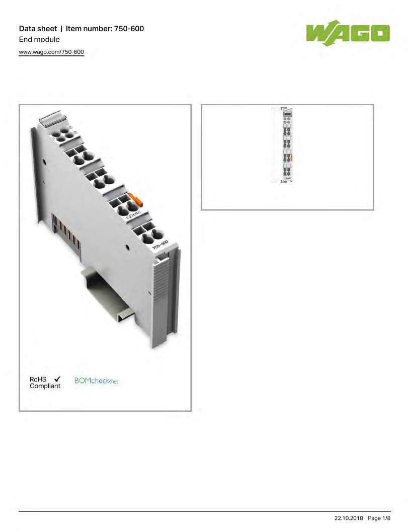
Data sheet | Item number: 750-600End modulewww.wago.com/750-600
22.10.2018 Page /1 8
RoHS .,¡' BOMcheckr.net Compl iant

Data sheet | Item number: 750-600www.wago.com/750-600
22.10.2018 Page /2 8
Item descriptionAfter the fieldbus node is assembled with the correct buscoupler and I/O modules, the end module is snapped onto the assembly.
It completes the internal data circuit and ensures correct data flow.
DataGeometrical Data
Width 12 mm / 0.472 inch
Height 69.8 mm / 2.748 inch
Height from upper-edge of DIN-35 rail 62.6 mm / 2.465 inch
Depth 100 mm / 3.937 inch
Mechanical data
Type of mounting DIN-35 rail
Material Data
Color light gray
Housing material Polycarbonate, polyamide 6.6
Fire load 1.083 MJ

Data sheet | Item number: 750-600www.wago.com/750-600
22.10.2018 Page /3 8
Fire load 1.083 MJ
Weight 32.298 g
Conformity marking CE
Environmental Requirements
Surrounding air (operating) temperature 0 … 55 °C
Surrounding air (storage) temperature -40 … 85 °C
Degree of protection IP20
Degree of pollution (5) 2 per IEC 61131-2
Operating altitude 0 … 2000 m
Mounting position horizontal (standing/lying) or vertical
Relative air humidity (no condensation) 95 %
Vibration resistance 4g per IEC 60068-2-6
Shock resistance 15g per IEC 60068-2-27
EMC immunity to interference acc. to EN 61000-6-2, marine applications
EMC emission of interference acc. to EN 61000-6-3, marine applications
Exposure to pollutants Per IEC 60068-2-42 and IEC 60068-2-43
Permissible H S contaminant concentration at a relative humidity < 2
75 %
10 ppm
Permissible SO contaminant concentration at a relative humidity < 2
75 %
25 ppm
Commercial data
Country of rigin DE
GTIN 4045454073985
Customs Tariff No. 85389091890
Product Group 15 (Remote I/O)
Approvals / Certificates
Ship Approvals
Logo Approval Certificate name
DNV GLDet Norske Veritas, Germanischer Lloyd
TAA0000194
DNVDNV Germany GmbH
A-14093
GLGermanischer Lloyd
26 898 - 05 HH

Data sheet | Item number: 750-600www.wago.com/750-600
22.10.2018 Page /4 8
Compatible productsCarrier rail
Item no.: 210-112Steel carrier rail; 35 x 7.5 mm; 1 mm thick; 2 m long; slotted; according to EN 60715; "Hole width 25 mm www.wago.com/210-112
Item no.: 210-113Steel carrier rail; 35 x 7.5 mm; 1 mm thick; 2 m long; unslotted; according to EN 60715 www.wago.com/210-113
Item no.: 210-114Steel carrier rail; 35 x 15 mm; 1.5 mm thick; 2 m long; unslotted; similar to EN 60715 www.wago.com/210-114
Item no.: 210-115Steel carrier rail; 35 x 7.5 mm; 1 mm thick; 2 m long; slotted; according to EN 60715; "Hole width 18 mm www.wago.com/210-115
Item no.: 210-118Steel carrier rail; 35 x 15 mm; 2.3 mm thick; 2 m long; unslotted; according to EN 60715 www.wago.com/210-118
Item no.: 210-196Aluminum carrier rail; 35 x 8.2 mm; 1.6 mm thick; 2 m long; unslotted; similar to EN 60715 www.wago.com/210-196
Item no.: 210-197Steel carrier rail; 35 x 15 mm; 1.5 mm thick; 2 m long; slotted; similar to EN 60715 www.wago.com/210-197
Item no.: 210-198Copper carrier rail; 35 x 15 mm; 2.3 mm thick; 2 m long; unslotted; according to EN 60715 www.wago.com/210-198
Item no.: 210-504Steel carrier rail; 35 x 7.5 mm; 1 mm thick; 2 m long; slotted; galvanized; according to EN 60715 www.wago.com/210-504
Item no.: 210-505Steel carrier rail; 35 x 7.5 mm; 1 mm thick; 2 m long; unslotted; galvanized; according to EN 60715 www.wago.com/210-505
Item no.: 210-506Steel carrier rail; 35 x 15 mm; 1.5 mm thick; 2 m long; unslotted; galvanized; similar to EN 60715 www.wago.com/210-506
Item no.: 210-508Steel carrier rail; 35 x 15 mm; 1.5 mm thick; 2 m long; slotted; galvanized; similar to EN 60715 www.wago.com/210-508
Marking accessories
Item no.: 2009-145Mini-WSB Inline; for smartPRINTER; on reel; stretchable 5 - 5.2 mm; plain; snap-on type www.wago.com/2009-145
Item no.: 2009-145/000-002Mini-WSB Inline; for smartPRINTER; on reel; stretchable 5 - 5.2 mm; plain; snap-on type
www.wago.com/2009-145/000-002
Item no.: 2009-145/000-005Mini-WSB Inline; for smartPRINTER; on reel; stretchable 5 - 5.2 mm; plain; snap-on type
www.wago.com/2009-145/000-005
Item no.: 2009-145/000-006

Data sheet | Item number: 750-600www.wago.com/750-600
22.10.2018 Page /5 8
Item no.: 2009-145/000-006Mini-WSB Inline; for smartPRINTER; on reel; stretchable 5 - 5.2 mm; plain; snap-on type
www.wago.com/2009-145/000-006
Item no.: 2009-145/000-007Mini-WSB Inline; plain; 1,700 Mini-WSB markers (5 mm) on roll; stretchable 5 - 5.2 mm
www.wago.com/2009-145/000-007
Item no.: 2009-145/000-012Mini-WSB Inline; for smartPRINTER; on reel; stretchable 5 - 5.2 mm; plain; snap-on type
www.wago.com/2009-145/000-012
Item no.: 2009-145/000-023Mini-WSB Inline; on reel; stretchable 5 - 5.2 mm; plain; snap-on type
www.wago.com/2009-145/000-023
Item no.: 2009-145/000-024Mini-WSB Inline; on reel; stretchable 5 - 5.2 mm; plain; snap-on type
www.wago.com/2009-145/000-024
Item no.: 248-501Miniature WSB Quick marking system; plain; Marker width 5 mm; 10 strips with 10 markers per card www.wago.com/248-501
Item no.: 248-501/000-002Mini-WSB marking card; as card; not stretchable; plain; snap-on type
www.wago.com/248-501/000-002
Item no.: 248-501/000-005Mini-WSB marking card; as card; plain; snap-on type
www.wago.com/248-501/000-005
Item no.: 248-501/000-006Mini-WSB marking card; as card; not stretchable; plain; snap-on type
www.wago.com/248-501/000-006
Item no.: 248-501/000-007Mini-WSB marking card; as card; not stretchable; plain; snap-on type
www.wago.com/248-501/000-007
Item no.: 248-501/000-012Mini-WSB marking card; as card; not stretchable; plain; snap-on type
www.wago.com/248-501/000-012
Item no.: 248-501/000-017Mini-WSB marking card; as card; not stretchable; plain; snap-on type
www.wago.com/248-501/000-017
Item no.: 248-501/000-023Mini-WSB marking card; as card; not stretchable; plain; snap-on type
www.wago.com/248-501/000-023
Item no.: 248-501/000-024Mini-WSB marking card; as card; not stretchable; plain; snap-on type
www.wago.com/248-501/000-024
Item no.: 750-100Marker card; as a DIN A4 sheet; plain www.wago.com/750-100
Item no.: 750-103 www.wago.com/750-103

Data sheet | Item number: 750-600www.wago.com/750-600
22.10.2018 Page /6 8
Item no.: 750-103Group marker carrier
www.wago.com/750-103
Item no.: 750-106Group marker carrier www.wago.com/750-106
system box
Item no.: 850-804IP65 enclosure; Stainless steel; WxHxD (400x123x200 mm); 4 x M20, 16 x M16, 28 x M12 cable grip www.wago.com/850-804
Item no.: 850-804/000-001IP65 enclosure; Stainless steel; WxHxD (400x123x200 mm); 2 x M20, 13 x M16, 32 x M12 cable grip
www.wago.com/850-804/000-001
Item no.: 850-805IP65 enclosure; Stainless steel; WxHxD (600x123x200 mm); 4 x M20, 19 x M16, 67 x M12 cable grip www.wago.com/850-805
Item no.: 850-814/002-000IP65 enclosure; Sheet steel (RAL 7035); WxHxD (200x120x200 mm); without flange plate
www.wago.com/850-814/002-000
Item no.: 850-815/002-000IP65 enclosure; Sheet steel (RAL 7035); WxHxD (300x120x200 mm); without flange plate
www.wago.com/850-815/002-000
Item no.: 850-816/002-000IP65 enclosure; Sheet steel (RAL 7035); WxHxD (400x120x200 mm); without flange plate
www.wago.com/850-816/002-000
Item no.: 850-817/002-000IP65 enclosure; Sheet steel (RAL 7035); WxHxD (600x120x200 mm); without flange plate
www.wago.com/850-817/002-000
Item no.: 850-825IP65 enclosure; Aluminium (RAL 7032); WxHxD (160x100x160 mm); 9 x M12, 4 x M20 www.wago.com/850-825
Item no.: 850-826IP65 enclosure; Aluminium (RAL 7032); WxHxD (240x100x160 mm); 4 x M20, 4 x M16, 14 x M12 cable grip
www.wago.com/850-826
Item no.: 850-826/002-000IP65 enclosure; Aluminium (RAL 7035); WxHxD (240x100x160 mm); 4 x M20, 4 x M16, 14 x M12 cable grip
www.wago.com/850-826/002-000
Item no.: 850-827IP65 enclosure; Aluminium (RAL 7032); WxHxD (320x100x160 mm); 4 x M20, 8 x M16, 17 x M12 cable grip
www.wago.com/850-827
Item no.: 850-827/002-000IP65 enclosure; Aluminium (RAL 7035); WxHxD (320x100x160 mm); 4 x M20, 8 x M16, 17 x M12 cable grip
www.wago.com/850-827/002-000
Item no.: 850-828IP65 enclosure; Aluminium (RAL 7032); WxHxD (480x100x160 mm); 4 x M20, 10 x M16, 35 x M12 cable grip
www.wago.com/850-828
Item no.: 850-828/002-000IP65 enclosure; Aluminium (RAL 7035); WxHxD (480x100x160 mm); 4 x M20, 10 x M16, 35 x M12 cable grip
www.wago.com/850-828/002-000
Item no.: 850-834

Data sheet | Item number: 750-600www.wago.com/750-600
22.10.2018 Page /7 8
Item no.: 850-834IP65 enclosure; Polyester (RAL 7032); WxHxD (164x100x164 mm); 9 x M12, 4 x M20 www.wago.com/850-834
Item no.: 850-835IP65 enclosure; Polyester (RAL 7032); WxHxD (244x100x164 mm); 4 x M20, 4 x M16, 14 x M12 cable grip
www.wago.com/850-835
Item no.: 850-836IP65 enclosure; Polyester (RAL 7032); WxHxD (324x100x164 mm); 4 x M20, 8 x M16, 17 x M12 cable grip
www.wago.com/850-836
shield connection
Item no.: 790-108Shield clamping saddle; 11 mm wide; diameter of compatible conductor www.wago.com/790-108
Item no.: 790-116Shield clamping saddle; 19 mm wide; diameter of compatible conductor; 7 ... 16 mm www.wago.com/790-116
Item no.: 790-124Shield clamping saddle; 27 mm wide; diameter of compatible conductor; 6 mm to 24 mm www.wago.com/790-124
Item no.: 790-140Shield clamping saddle; 43 mm wide; diameter of compatible conductor; 22 mm to 40 mm www.wago.com/790-140
Item no.: 790-208Shield clamping saddle; 12.4 mm wide; 3 ... 8 mm www.wago.com/790-208
Item no.: 790-216Shield clamping saddle; 6–16 mm diameter; 21.8 mm wide www.wago.com/790-216
Item no.: 790-220Shield clamping saddle; 6–20 mm diameter; 30 mm wide www.wago.com/790-220
DownloadsDocumentation
Manual
End modulefor integration of the internal data bus
13-oct-20151.8 MB
Download
Bid Text
750-600IO-Klemmen
21-ene-2016 DOC25.6 kB
Download
System Description
Overview on WAGO-I/O-SYSTEM 750 approvals 06-jun-2017314.9 kB
Download
750/753 Series I/O-System ‒ General Product Information 29-may-20182.0 MB
Download
Design Notes 03-may-2011 Download

Data sheet | Item number: 750-600www.wago.com/750-600
22.10.2018 Page /8 8
Subject to changes.
WAGO Kontakttechnik GmbH & Co. KG Hansastr. 27 32423 Minden Phone: +49571 887-0 | Fax: +49571 887-169 Email: [email protected] | Web: www.wago.com
Do you have any questions about our products? We are always happy to take your call at +49 (571) 887-44222.
Design NotesBasic conditions and recommendations for higher operational safety
03-may-20111.5 MB
Download
Use in Hazardous EnvironmentsTerm definition, marking and installation regulations
08-may-20141.0 MB
Download
smartDATA
CAD data
3D Download 750-600 URL Download
Device Files
Device Driver
WAGO USB Service Cable Driver / 750 and 857 Series 6.5.3.010-sep-2014
ZIP4.8 MB
Download
Product family
750/753 Series I/O-SystemShow all products from the family.

Data sheet | Item number: 750-5978-channel analog output; 0 … 10 V/±10 VDCwww.wago.com/750-597
22.10.2018 Page /1 9
RoHS .,¡' Compl iant
BOMcheckr.net
Status A01 ... AOa
'O, '02
' 03
'O. ' 05
' 06
' 07
'OB
" 7"''''.Jn .Jl\.
'1 Error ' , , " , , t--- Oata conlacls , , · " , " ;,' M
~ li. M
I~ ~ M
-11"; M
• • '" M
-J¡ M
• • '" M
~n M
'-- Power jumpercontacts

Data sheet | Item number: 750-597www.wago.com/750-597
22.10.2018 Page /2 9
Item description
The analog output module generates signals of a standard magnitude 0–10 V and ±10V.
The output signal is electrically isolated and transmitted with a resolution of 12 bits.
Both the internal system and 24V field side supply power the module.
The output channels of the module have a common ground potential.
The bus module detects a 24 V field supply failure. The status is transmitted to the fieldbus coupler and indicated by an LED.
The module can be configured via WAGO‐I/O‐CHECK or GSD files.
DataTechnical Data
Number of analog outputs 8
Total number of channels (module) 8
Type of signal Voltage
Type of signal voltage DC 0 … 10 V
Actuator connection 8 x (2-conductor)
Resolution [bit] 12 Bit

Data sheet | Item number: 750-597www.wago.com/750-597
22.10.2018 Page /3 9
Resolution [bit] 12 Bit
Bit width 8 x 16-bit data; 8 x 8-bit control/status (optional)
Load impedance (output/voltage) ≥ 2kΩ
Conversion time (typ.) 13 ms
Measurement error, reference temperature 25 °C
Measurement error, deviation max. from the upper-range value 0.1 %
Temperature coefficient ≤ ± 10 ppm/K of the largest output area
Field supply voltage DC 24 V (-15 … 30 %); über Leistungskontakte; zur Weiterleitung getunnelt
System supply voltage DC 5 V; via data contacts
Current consumption, system supply (5 V) 61 mA
Isolation 500 V system/field
Number of incoming power jumper contacts 2
Number of outgoing power jumper contacts 2
Connection data
Connection technology: inputs/outputs 16 x Push-in CAGE CLAMP®
Connection type (1) Inputs/Outputs
Solid conductor 0.08 … 1.5 mm² / 28 … 16 AWG
Fine-stranded conductor 0.25 … 1.5 mm² / 22 … 16 AWG
Strip length 8 … 9 mm / 0.31 … 0.35 Inch
Geometrical Data
Width 12 mm / 0.472 inch
Height 69 mm / 2.717 inch
Height from upper-edge of DIN-35 rail 61.8 mm / 2.433 inch
Depth 100 mm / 3.937 inch
Mechanical data
Type of mounting DIN-35 rail
Material Data
Housing material Polycarbonate, polyamide 6.6
Weight 48 g
Conformity marking CE
Environmental Requirements
Surrounding air (operating) temperature 0 … 55 °C
Surrounding air (storage) temperature -40 … 85 °C
Degree of protection IP20
Degree of pollution (5) 2 per IEC 61131-2

Data sheet | Item number: 750-597www.wago.com/750-597
22.10.2018 Page /4 9
Degree of pollution (5) 2 per IEC 61131-2
Operating altitude 0 … 2000 m
Mounting position horizontal (standing/lying) or vertical
Relative air humidity (no condensation) 95 %
Vibration resistance acc. to IEC 60068-2-6
Shock resistance 15g per IEC 60068-2-27
EMC immunity to interference acc. to EN 61000-6-2
EMC emission of interference acc. to EN 61000-6-3
Exposure to pollutants Per IEC 60068-2-42 and IEC 60068-2-43
Permissible H S contaminant concentration at a relative humidity < 2
75 %
10 ppm
Permissible SO contaminant concentration at a relative humidity < 2
75 %
25 ppm
Commercial data
Country of rigin DE
GTIN 4055143432146
Customs Tariff No. 85389099990
Compatible productssystem box
Item no.: 850-804IP65 enclosure; Stainless steel; WxHxD (400x123x200 mm); 4 x M20, 16 x M16, 28 x M12 cable grip www.wago.com/850-804
Item no.: 850-804/000-001IP65 enclosure; Stainless steel; WxHxD (400x123x200 mm); 2 x M20, 13 x M16, 32 x M12 cable grip
www.wago.com/850-804/000-001
Item no.: 850-805IP65 enclosure; Stainless steel; WxHxD (600x123x200 mm); 4 x M20, 19 x M16, 67 x M12 cable grip www.wago.com/850-805
Item no.: 850-814/002-000IP65 enclosure; Sheet steel (RAL 7035); WxHxD (200x120x200 mm); without flange plate
www.wago.com/850-814/002-000
Item no.: 850-815/002-000IP65 enclosure; Sheet steel (RAL 7035); WxHxD (300x120x200 mm); without flange plate
www.wago.com/850-815/002-000
Item no.: 850-816/002-000IP65 enclosure; Sheet steel (RAL 7035); WxHxD (400x120x200 mm); without flange plate
www.wago.com/850-816/002-000
Item no.: 850-817/002-000IP65 enclosure; Sheet steel (RAL 7035); WxHxD (600x120x200 mm); without flange plate
www.wago.com/850-817/002-000
Item no.: 850-825 www.wago.com/850-825

Data sheet | Item number: 750-597www.wago.com/750-597
22.10.2018 Page /5 9
Item no.: 850-825IP65 enclosure; Aluminium (RAL 7032); WxHxD (160x100x160 mm); 9 x M12, 4 x M20
www.wago.com/850-825
Item no.: 850-826IP65 enclosure; Aluminium (RAL 7032); WxHxD (240x100x160 mm); 4 x M20, 4 x M16, 14 x M12 cable grip
www.wago.com/850-826
Item no.: 850-826/002-000IP65 enclosure; Aluminium (RAL 7035); WxHxD (240x100x160 mm); 4 x M20, 4 x M16, 14 x M12 cable grip
www.wago.com/850-826/002-000
Item no.: 850-827IP65 enclosure; Aluminium (RAL 7032); WxHxD (320x100x160 mm); 4 x M20, 8 x M16, 17 x M12 cable grip
www.wago.com/850-827
Item no.: 850-827/002-000IP65 enclosure; Aluminium (RAL 7035); WxHxD (320x100x160 mm); 4 x M20, 8 x M16, 17 x M12 cable grip
www.wago.com/850-827/002-000
Item no.: 850-828IP65 enclosure; Aluminium (RAL 7032); WxHxD (480x100x160 mm); 4 x M20, 10 x M16, 35 x M12 cable grip
www.wago.com/850-828
Item no.: 850-828/002-000IP65 enclosure; Aluminium (RAL 7035); WxHxD (480x100x160 mm); 4 x M20, 10 x M16, 35 x M12 cable grip
www.wago.com/850-828/002-000
Item no.: 850-834IP65 enclosure; Polyester (RAL 7032); WxHxD (164x100x164 mm); 9 x M12, 4 x M20 www.wago.com/850-834
Item no.: 850-835IP65 enclosure; Polyester (RAL 7032); WxHxD (244x100x164 mm); 4 x M20, 4 x M16, 14 x M12 cable grip
www.wago.com/850-835
Item no.: 850-836IP65 enclosure; Polyester (RAL 7032); WxHxD (324x100x164 mm); 4 x M20, 8 x M16, 17 x M12 cable grip
www.wago.com/850-836
Carrier rail
Item no.: 210-112Steel carrier rail; 35 x 7.5 mm; 1 mm thick; 2 m long; slotted; according to EN 60715; "Hole width 25 mm www.wago.com/210-112
Item no.: 210-113Steel carrier rail; 35 x 7.5 mm; 1 mm thick; 2 m long; unslotted; according to EN 60715 www.wago.com/210-113
Item no.: 210-114Steel carrier rail; 35 x 15 mm; 1.5 mm thick; 2 m long; unslotted; similar to EN 60715 www.wago.com/210-114
Item no.: 210-115Steel carrier rail; 35 x 7.5 mm; 1 mm thick; 2 m long; slotted; according to EN 60715; "Hole width 18 mm www.wago.com/210-115
Item no.: 210-118Steel carrier rail; 35 x 15 mm; 2.3 mm thick; 2 m long; unslotted; according to EN 60715 www.wago.com/210-118
Item no.: 210-196Aluminum carrier rail; 35 x 8.2 mm; 1.6 mm thick; 2 m long; unslotted; similar to EN 60715 www.wago.com/210-196
Item no.: 210-197Steel carrier rail; 35 x 15 mm; 1.5 mm thick; 2 m long; slotted; similar to EN 60715 www.wago.com/210-197
Item no.: 210-198 www.wago.com/210-198

Data sheet | Item number: 750-597www.wago.com/750-597
22.10.2018 Page /6 9
Item no.: 210-198Copper carrier rail; 35 x 15 mm; 2.3 mm thick; 2 m long; unslotted; according to EN 60715
www.wago.com/210-198
Item no.: 210-504Steel carrier rail; 35 x 7.5 mm; 1 mm thick; 2 m long; slotted; galvanized; according to EN 60715 www.wago.com/210-504
Item no.: 210-505Steel carrier rail; 35 x 7.5 mm; 1 mm thick; 2 m long; unslotted; galvanized; according to EN 60715 www.wago.com/210-505
Item no.: 210-506Steel carrier rail; 35 x 15 mm; 1.5 mm thick; 2 m long; unslotted; galvanized; similar to EN 60715 www.wago.com/210-506
Item no.: 210-508Steel carrier rail; 35 x 15 mm; 1.5 mm thick; 2 m long; slotted; galvanized; similar to EN 60715 www.wago.com/210-508
tools
Item no.: 210-719Operating tool with partially insulated shaft; Type 1, blade (2.5 x 0.4) mm www.wago.com/210-719
Marking accessories
Item no.: 2009-145Mini-WSB Inline; for smartPRINTER; on reel; stretchable 5 - 5.2 mm; plain; snap-on type www.wago.com/2009-145
Item no.: 2009-145/000-002Mini-WSB Inline; for smartPRINTER; on reel; stretchable 5 - 5.2 mm; plain; snap-on type
www.wago.com/2009-145/000-002
Item no.: 2009-145/000-005Mini-WSB Inline; for smartPRINTER; on reel; stretchable 5 - 5.2 mm; plain; snap-on type
www.wago.com/2009-145/000-005
Item no.: 2009-145/000-006Mini-WSB Inline; for smartPRINTER; on reel; stretchable 5 - 5.2 mm; plain; snap-on type
www.wago.com/2009-145/000-006
Item no.: 2009-145/000-007Mini-WSB Inline; plain; 1,700 Mini-WSB markers (5 mm) on roll; stretchable 5 - 5.2 mm
www.wago.com/2009-145/000-007
Item no.: 2009-145/000-012Mini-WSB Inline; for smartPRINTER; on reel; stretchable 5 - 5.2 mm; plain; snap-on type
www.wago.com/2009-145/000-012
Item no.: 2009-145/000-023Mini-WSB Inline; on reel; stretchable 5 - 5.2 mm; plain; snap-on type
www.wago.com/2009-145/000-023
Item no.: 2009-145/000-024Mini-WSB Inline; on reel; stretchable 5 - 5.2 mm; plain; snap-on type
www.wago.com/2009-145/000-024
Item no.: 248-501Miniature WSB Quick marking system; plain; Marker width 5 mm; 10 strips with 10 markers per card www.wago.com/248-501
Item no.: 248-501/000-002Mini-WSB marking card; as card; not stretchable; plain; snap-on type
www.wago.com/248-501/000-002

Data sheet | Item number: 750-597www.wago.com/750-597
22.10.2018 Page /7 9
Item no.: 248-501/000-005Mini-WSB marking card; as card; plain; snap-on type
www.wago.com/248-501/000-005
Item no.: 248-501/000-006Mini-WSB marking card; as card; not stretchable; plain; snap-on type
www.wago.com/248-501/000-006
Item no.: 248-501/000-007Mini-WSB marking card; as card; not stretchable; plain; snap-on type
www.wago.com/248-501/000-007
Item no.: 248-501/000-012Mini-WSB marking card; as card; not stretchable; plain; snap-on type
www.wago.com/248-501/000-012
Item no.: 248-501/000-017Mini-WSB marking card; as card; not stretchable; plain; snap-on type
www.wago.com/248-501/000-017
Item no.: 248-501/000-023Mini-WSB marking card; as card; not stretchable; plain; snap-on type
www.wago.com/248-501/000-023
Item no.: 248-501/000-024Mini-WSB marking card; as card; not stretchable; plain; snap-on type
www.wago.com/248-501/000-024
Item no.: 750-103Group marker carrier www.wago.com/750-103
Item no.: 750-107Group marker carrier www.wago.com/750-107
Supply module
Item no.: 750-601Power Supply; 24 VDC www.wago.com/750-601
Item no.: 750-602Power Supply; 24 VDC www.wago.com/750-602
Item no.: 750-610Power Supply; 24 VDC; fuse holder; Diagnostics www.wago.com/750-610
Item no.: 750-612Power Supply; 0 … 230 V AC/DC www.wago.com/750-612
shield connection
Item no.: 790-108Shield clamping saddle; 11 mm wide; diameter of compatible conductor www.wago.com/790-108
Item no.: 790-116Shield clamping saddle; 19 mm wide; diameter of compatible conductor; 7 ... 16 mm www.wago.com/790-116
Item no.: 790-124 www.wago.com/790-124

Data sheet | Item number: 750-597www.wago.com/750-597
22.10.2018 Page /8 9
Item no.: 790-124Shield clamping saddle; 27 mm wide; diameter of compatible conductor; 6 mm to 24 mm
www.wago.com/790-124
Item no.: 790-140Shield clamping saddle; 43 mm wide; diameter of compatible conductor; 22 mm to 40 mm www.wago.com/790-140
Item no.: 790-208Shield clamping saddle; 12.4 mm wide; 3 ... 8 mm www.wago.com/790-208
Item no.: 790-216Shield clamping saddle; 6–16 mm diameter; 21.8 mm wide www.wago.com/790-216
Item no.: 790-220Shield clamping saddle; 6–20 mm diameter; 30 mm wide www.wago.com/790-220
DownloadsDocumentation
Manual
8-channel, 0-10VDC / ±10VDC 04-may-20165.1 MB
Download
Bid Text
750-597 10-mar-2017 DOC29.2 kB
Download
System Description
Overview on WAGO-I/O-SYSTEM 750 approvals 06-jun-2017314.9 kB
Download
750/753 Series I/O-System ‒ General Product Information 29-may-20182.0 MB
Download
Design NotesBasic conditions and recommendations for higher operational safety
03-may-20111.5 MB
Download
Use in Hazardous EnvironmentsTerm definition, marking and installation regulations
08-may-20141.0 MB
Download
Application Notes
Application Note CoDeSys 2.3
Application Note Library ModuleAccess_01These instructions describe the use of the ModuleAccess_01.lib library using 4 examples.
29-ene-20161.0 MB
Download

Data sheet | Item number: 750-597www.wago.com/750-597
22.10.2018 Page /9 9
Subject to changes.
WAGO Kontakttechnik GmbH & Co. KG Hansastr. 27 32423 Minden Phone: +49571 887-0 | Fax: +49571 887-169 Email: [email protected] | Web: www.wago.com
Do you have any questions about our products? We are always happy to take your call at +49 (571) 887-44222.
Libraries
Library
ModuleAccess_01.libThe ModuleAccess_01 library provides both module configuration and access to its process data within a CoDeSys project without the use of WAGO I/O Check.
16-feb-20181.5 MB
Download
smartDATA
CAD data
3D Download 750-597 URL Download
Product family
750/753 Series I/O-SystemShow all products from the family.

Data sheet | Item number: 750-5594-channel analog output; 0 ... 10 VDCwww.wago.com/750-559
22.10.2018 Page /1 10
RoHS .,¡' Compliant
BOMcheckr.net
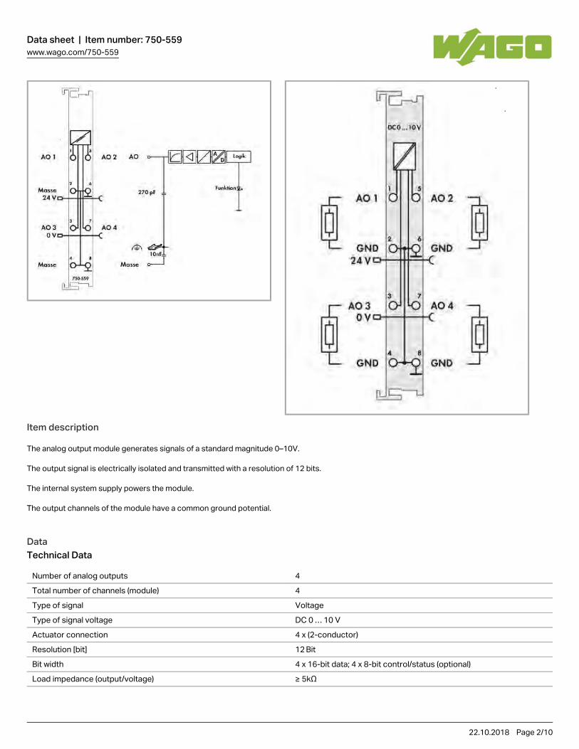
Data sheet | Item number: 750-559www.wago.com/750-559
22.10.2018 Page /2 10
Item description
The analog output module generates signals of a standard magnitude 0–10V.
The output signal is electrically isolated and transmitted with a resolution of 12 bits.
The internal system supply powers the module.
The output channels of the module have a common ground potential.
DataTechnical Data
Number of analog outputs 4
Total number of channels (module) 4
Type of signal Voltage
Type of signal voltage DC 0 … 10 V
Actuator connection 4 x (2-conductor)
Resolution [bit] 12 Bit
Bit width 4 x 16-bit data; 4 x 8-bit control/status (optional)
Load impedance (output/voltage) ≥ 5kΩ
Conversion time (typ.) 10 ms

Data sheet | Item number: 750-559www.wago.com/750-559
22.10.2018 Page /3 10
Conversion time (typ.) 10 ms
Measurement error, reference temperature 25 °C
Measurement error, deviation max. from the upper-range value 0.1 %
Temperature error max. from the upper-range value 0.01 %/K
Recovery time (typ.) 100 ms
Field supply voltage DC 24 V (-25 … 30 %); über Leistungskontakte; zur Weiterleitung getunnelt
System supply voltage DC 5 V; via data contacts
Current consumption, system supply (5 V) 125 mA
Isolation 500 V system/supply
Number of incoming power jumper contacts 2
Number of outgoing power jumper contacts 2
Current carrying capacity of the power jumper contacts 10 A
Connection data
Connection technology: inputs/outputs 8 x CAGE CLAMP®
Connection type (1) Inputs/Outputs
Solid conductor 0.08 … 2.5 mm² / 28 … 14 AWG
Fine-stranded conductor 0.08 … 2.5 mm² / 28 … 14 AWG
Strip length 8 … 9 mm / 0.31 … 0.35 Inch
Geometrical Data
Width 12 mm / 0.472 inch
Height 69.8 mm / 2.748 inch
Height from upper-edge of DIN-35 rail 62.6 mm / 2.465 inch
Depth 100 mm / 3.937 inch
Mechanical data
Type of mounting DIN-35 rail
Material Data
Color light gray
Housing material Polycarbonate, polyamide 6.6
Fire load 1.222 MJ
Weight 51 g
Conformity marking CE
Environmental Requirements
Surrounding air (operating) temperature 0 … 55 °C
Surrounding air (storage) temperature -40 … 85 °C
Degree of protection IP20

Data sheet | Item number: 750-559www.wago.com/750-559
22.10.2018 Page /4 10
Degree of protection IP20
Degree of pollution (5) 2 per IEC 61131-2
Operating altitude 0 … 2000 m
Mounting position horizontal (standing/lying) or vertical
Relative air humidity (no condensation) 95 %
Vibration resistance 4g per IEC 60068-2-6
Shock resistance 15g per IEC 60068-2-27
EMC immunity to interference acc. to EN 61000-6-2, marine applications
EMC emission of interference acc. to EN 61000-6-4, marine applications
Exposure to pollutants Per IEC 60068-2-42 and IEC 60068-2-43
Permissible H S contaminant concentration at a relative humidity < 2
75 %
10 ppm
Permissible SO contaminant concentration at a relative humidity < 2
75 %
25 ppm
Commercial data
Country of rigin DE
GTIN 4045454490447
Customs Tariff No. 85389099990
Product Group 15 (Remote I/O)
Approvals / Certificates
Ex-Approvals
Logo Approval Certificate name
ATEXTUEV Nord Cert GmbH
TÜV 07 ATEX 554086 X en.
TUEV NordTUEV Nord Cert GmbH
IECEx TUN 09.0001 X
ULUnderwriters Laboratories Inc. (HAZARDOUS LOCATIONS)
E198726 Sec.1 (HAZARDOUS LOCATIONS)
Ship Approvals
Logo Approval Certificate name
ABSAmerican Bureau of Shipping
16-HG1554285-PDA
BV 13453/DO BV

Data sheet | Item number: 750-559www.wago.com/750-559
22.10.2018 Page /5 10
BVBureau Veritas S.A.
13453/DO BV
DNV GLDet Norske Veritas, Germanischer Lloyd
TAA0000194
DNVDNV Germany GmbH
A-14093
GLGermanischer Lloyd
26 898 - 05 HH
LR{Lloyds Register EMEA
02/20026 (E5)
NKNippon Kaiji Kyokai
TA17255M
PRSPolski Rejetr Statkow
TE/1989/880590/13
RINARINA Germany GmbH
ELE134212XG
UL-Approvals
Logo Approval Certificate name
ULUL International Netherlands B.V. (ORDINARY LOCATIONS)
E175199 Sec.1 (ORDINARY LOCATIONS)
Compatible productssystem box
Item no.: 850-804IP65 enclosure; Stainless steel; WxHxD (400x123x200 mm); 4 x M20, 16 x M16, 28 x M12 cable grip www.wago.com/850-804
Item no.: 850-804/000-001IP65 enclosure; Stainless steel; WxHxD (400x123x200 mm); 2 x M20, 13 x M16, 32 x M12 cable grip
www.wago.com/850-804/000-001
Item no.: 850-805 www.wago.com/850-805

Data sheet | Item number: 750-559www.wago.com/750-559
22.10.2018 Page /6 10
Item no.: 850-805IP65 enclosure; Stainless steel; WxHxD (600x123x200 mm); 4 x M20, 19 x M16, 67 x M12 cable grip
www.wago.com/850-805
Item no.: 850-814/002-000IP65 enclosure; Sheet steel (RAL 7035); WxHxD (200x120x200 mm); without flange plate
www.wago.com/850-814/002-000
Item no.: 850-815/002-000IP65 enclosure; Sheet steel (RAL 7035); WxHxD (300x120x200 mm); without flange plate
www.wago.com/850-815/002-000
Item no.: 850-816/002-000IP65 enclosure; Sheet steel (RAL 7035); WxHxD (400x120x200 mm); without flange plate
www.wago.com/850-816/002-000
Item no.: 850-817/002-000IP65 enclosure; Sheet steel (RAL 7035); WxHxD (600x120x200 mm); without flange plate
www.wago.com/850-817/002-000
Item no.: 850-825IP65 enclosure; Aluminium (RAL 7032); WxHxD (160x100x160 mm); 9 x M12, 4 x M20 www.wago.com/850-825
Item no.: 850-826IP65 enclosure; Aluminium (RAL 7032); WxHxD (240x100x160 mm); 4 x M20, 4 x M16, 14 x M12 cable grip
www.wago.com/850-826
Item no.: 850-826/002-000IP65 enclosure; Aluminium (RAL 7035); WxHxD (240x100x160 mm); 4 x M20, 4 x M16, 14 x M12 cable grip
www.wago.com/850-826/002-000
Item no.: 850-827IP65 enclosure; Aluminium (RAL 7032); WxHxD (320x100x160 mm); 4 x M20, 8 x M16, 17 x M12 cable grip
www.wago.com/850-827
Item no.: 850-827/002-000IP65 enclosure; Aluminium (RAL 7035); WxHxD (320x100x160 mm); 4 x M20, 8 x M16, 17 x M12 cable grip
www.wago.com/850-827/002-000
Item no.: 850-828IP65 enclosure; Aluminium (RAL 7032); WxHxD (480x100x160 mm); 4 x M20, 10 x M16, 35 x M12 cable grip
www.wago.com/850-828
Item no.: 850-828/002-000IP65 enclosure; Aluminium (RAL 7035); WxHxD (480x100x160 mm); 4 x M20, 10 x M16, 35 x M12 cable grip
www.wago.com/850-828/002-000
Item no.: 850-834IP65 enclosure; Polyester (RAL 7032); WxHxD (164x100x164 mm); 9 x M12, 4 x M20 www.wago.com/850-834
Item no.: 850-835IP65 enclosure; Polyester (RAL 7032); WxHxD (244x100x164 mm); 4 x M20, 4 x M16, 14 x M12 cable grip
www.wago.com/850-835
Item no.: 850-836IP65 enclosure; Polyester (RAL 7032); WxHxD (324x100x164 mm); 4 x M20, 8 x M16, 17 x M12 cable grip
www.wago.com/850-836
shield connection
Item no.: 790-108Shield clamping saddle; 11 mm wide; diameter of compatible conductor www.wago.com/790-108
Item no.: 790-116

Data sheet | Item number: 750-559www.wago.com/750-559
22.10.2018 Page /7 10
Item no.: 790-116Shield clamping saddle; 19 mm wide; diameter of compatible conductor; 7 ... 16 mm www.wago.com/790-116
Item no.: 790-124Shield clamping saddle; 27 mm wide; diameter of compatible conductor; 6 mm to 24 mm www.wago.com/790-124
Item no.: 790-140Shield clamping saddle; 43 mm wide; diameter of compatible conductor; 22 mm to 40 mm www.wago.com/790-140
Item no.: 790-208Shield clamping saddle; 12.4 mm wide; 3 ... 8 mm www.wago.com/790-208
Item no.: 790-216Shield clamping saddle; 6–16 mm diameter; 21.8 mm wide www.wago.com/790-216
Item no.: 790-220Shield clamping saddle; 6–20 mm diameter; 30 mm wide www.wago.com/790-220
Carrier rail
Item no.: 210-112Steel carrier rail; 35 x 7.5 mm; 1 mm thick; 2 m long; slotted; according to EN 60715; "Hole width 25 mm www.wago.com/210-112
Item no.: 210-113Steel carrier rail; 35 x 7.5 mm; 1 mm thick; 2 m long; unslotted; according to EN 60715 www.wago.com/210-113
Item no.: 210-114Steel carrier rail; 35 x 15 mm; 1.5 mm thick; 2 m long; unslotted; similar to EN 60715 www.wago.com/210-114
Item no.: 210-115Steel carrier rail; 35 x 7.5 mm; 1 mm thick; 2 m long; slotted; according to EN 60715; "Hole width 18 mm www.wago.com/210-115
Item no.: 210-118Steel carrier rail; 35 x 15 mm; 2.3 mm thick; 2 m long; unslotted; according to EN 60715 www.wago.com/210-118
Item no.: 210-196Aluminum carrier rail; 35 x 8.2 mm; 1.6 mm thick; 2 m long; unslotted; similar to EN 60715 www.wago.com/210-196
Item no.: 210-197Steel carrier rail; 35 x 15 mm; 1.5 mm thick; 2 m long; slotted; similar to EN 60715 www.wago.com/210-197
Item no.: 210-198Copper carrier rail; 35 x 15 mm; 2.3 mm thick; 2 m long; unslotted; according to EN 60715 www.wago.com/210-198
Item no.: 210-504Steel carrier rail; 35 x 7.5 mm; 1 mm thick; 2 m long; slotted; galvanized; according to EN 60715 www.wago.com/210-504
Item no.: 210-505Steel carrier rail; 35 x 7.5 mm; 1 mm thick; 2 m long; unslotted; galvanized; according to EN 60715 www.wago.com/210-505
Item no.: 210-506Steel carrier rail; 35 x 15 mm; 1.5 mm thick; 2 m long; unslotted; galvanized; similar to EN 60715 www.wago.com/210-506
Item no.: 210-508Steel carrier rail; 35 x 15 mm; 1.5 mm thick; 2 m long; slotted; galvanized; similar to EN 60715 www.wago.com/210-508
Marking accessories
Item no.: 2009-145Mini-WSB Inline; for smartPRINTER; on reel; stretchable 5 - 5.2 mm; plain; snap-on type www.wago.com/2009-145

Data sheet | Item number: 750-559www.wago.com/750-559
22.10.2018 Page /8 10
Item no.: 2009-145Mini-WSB Inline; for smartPRINTER; on reel; stretchable 5 - 5.2 mm; plain; snap-on type www.wago.com/2009-145
Item no.: 2009-145/000-002Mini-WSB Inline; for smartPRINTER; on reel; stretchable 5 - 5.2 mm; plain; snap-on type
www.wago.com/2009-145/000-002
Item no.: 2009-145/000-005Mini-WSB Inline; for smartPRINTER; on reel; stretchable 5 - 5.2 mm; plain; snap-on type
www.wago.com/2009-145/000-005
Item no.: 2009-145/000-006Mini-WSB Inline; for smartPRINTER; on reel; stretchable 5 - 5.2 mm; plain; snap-on type
www.wago.com/2009-145/000-006
Item no.: 2009-145/000-007Mini-WSB Inline; plain; 1,700 Mini-WSB markers (5 mm) on roll; stretchable 5 - 5.2 mm
www.wago.com/2009-145/000-007
Item no.: 2009-145/000-012Mini-WSB Inline; for smartPRINTER; on reel; stretchable 5 - 5.2 mm; plain; snap-on type
www.wago.com/2009-145/000-012
Item no.: 2009-145/000-023Mini-WSB Inline; on reel; stretchable 5 - 5.2 mm; plain; snap-on type
www.wago.com/2009-145/000-023
Item no.: 2009-145/000-024Mini-WSB Inline; on reel; stretchable 5 - 5.2 mm; plain; snap-on type
www.wago.com/2009-145/000-024
Item no.: 248-501Miniature WSB Quick marking system; plain; Marker width 5 mm; 10 strips with 10 markers per card www.wago.com/248-501
Item no.: 248-501/000-002Mini-WSB marking card; as card; not stretchable; plain; snap-on type
www.wago.com/248-501/000-002
Item no.: 248-501/000-005Mini-WSB marking card; as card; plain; snap-on type
www.wago.com/248-501/000-005
Item no.: 248-501/000-006Mini-WSB marking card; as card; not stretchable; plain; snap-on type
www.wago.com/248-501/000-006
Item no.: 248-501/000-007Mini-WSB marking card; as card; not stretchable; plain; snap-on type
www.wago.com/248-501/000-007
Item no.: 248-501/000-012Mini-WSB marking card; as card; not stretchable; plain; snap-on type
www.wago.com/248-501/000-012
Item no.: 248-501/000-017Mini-WSB marking card; as card; not stretchable; plain; snap-on type
www.wago.com/248-501/000-017
Item no.: 248-501/000-023 www.wago.com/248-501

Data sheet | Item number: 750-559www.wago.com/750-559
22.10.2018 Page /9 10
Item no.: 248-501/000-023Mini-WSB marking card; as card; not stretchable; plain; snap-on type
www.wago.com/248-501/000-023
Item no.: 248-501/000-024Mini-WSB marking card; as card; not stretchable; plain; snap-on type
www.wago.com/248-501/000-024
Item no.: 750-100Marker card; as a DIN A4 sheet; plain www.wago.com/750-100
Item no.: 750-103Group marker carrier www.wago.com/750-103
Item no.: 750-106Group marker carrier www.wago.com/750-106
DownloadsDocumentation
Manual
4-channel, 0 - 10VDC 20-ene-20164.1 MB
Download
Bid Text
750-559IO-Klemmen
20-ene-2016 DOC28.2 kB
Download
System Description
750/753 Series I/O-System ‒ General Product Information 29-may-20182.0 MB
Download
Use in Hazardous EnvironmentsTerm definition, marking and installation regulations
08-may-20141.0 MB
Download
Overview on WAGO-I/O-SYSTEM 750 approvals 06-jun-2017314.9 kB
Download
Design NotesBasic conditions and recommendations for higher operational safety
03-may-20111.5 MB
Download
smartDATA
CAD data
3D Download 750-559 URL Download
Device Files

Data sheet | Item number: 750-559www.wago.com/750-559
22.10.2018 Page /10 10
Subject to changes.
WAGO Kontakttechnik GmbH & Co. KG Hansastr. 27 32423 Minden Phone: +49571 887-0 | Fax: +49571 887-169 Email: [email protected] | Web: www.wago.com
Do you have any questions about our products? We are always happy to take your call at +49 (571) 887-44222.
Device Files
Device Driver
WAGO USB Service Cable Driver / 750 and 857 Series 6.5.3.010-sep-2014
ZIP4.8 MB
Download
Product family
750/753 Series I/O-SystemShow all products from the family.

Data sheet | Item number: 750-5502-channel analog output; 0 ... 10 VDCwww.wago.com/750-550
22.10.2018 Page /1 10
RoHS .,¡' Compl iant
\
BOMcheckr.net
A01
Igroundl
Shield (screen)
functionA02
Data contacls
A02
O CommGn Igroundl
Shield (screen)

Data sheet | Item number: 750-550www.wago.com/750-550
22.10.2018 Page /2 10
Item description
The analog output module generates signals of a standard magnitude 0–10V.
The output signal is electrically isolated and transmitted with a resolution of 12 bits.
The outputs are short-circuit proof.
The internal system supply powers the module.
The output channels have one common ground potential.
DataTechnical Data
Number of analog outputs 2
Total number of channels (module) 2
Type of signal Voltage
Type of signal voltage DC 0 … 10 V
Actuator connection 2 x (2-conductor)
Resolution [bit] 12 Bit
Bit width 2 x 16-bit data; 2 x 8-bit control/status (optional)
Load impedance (output/voltage) ≥ 5kΩ

Data sheet | Item number: 750-550www.wago.com/750-550
22.10.2018 Page /3 10
Load impedance (output/voltage) ≥ 5kΩ
Conversion time (typ.) 2 ms
Measurement error, reference temperature 25 °C
Measurement error, deviation max. from the upper-range value 0.1 %
Temperature error max. from the upper-range value 0.01 %/K
Recovery time (typ.) 0.3 ms
Linearity ±10 mV
System supply voltage DC 5 V; via data contacts
Current consumption, system supply (5 V) 65 mA
Isolation 500 V system/supply
Connection data
Connection technology: inputs/outputs 8 x CAGE CLAMP®
Connection type (1) Inputs/Outputs
Solid conductor 0.08 … 2.5 mm² / 28 … 14 AWG
Fine-stranded conductor 0.08 … 2.5 mm² / 28 … 14 AWG
Strip length 8 … 9 mm / 0.31 … 0.35 Inch
Geometrical Data
Width 12 mm / 0.472 inch
Height 69.8 mm / 2.748 inch
Height from upper-edge of DIN-35 rail 62.6 mm / 2.465 inch
Depth 100 mm / 3.937 inch
Mechanical data
Type of mounting DIN-35 rail
Material Data
Color light gray
Housing material Polycarbonate, polyamide 6.6
Weight 47.913 g
Conformity marking CE
Environmental Requirements
Surrounding air (operating) temperature 0 … 55 °C
Surrounding air (storage) temperature -40 … 85 °C
Degree of protection IP20
Degree of pollution (5) 2 per IEC 61131-2
Operating altitude 0 … 2000 m
Mounting position horizontal (standing/lying) or vertical

Data sheet | Item number: 750-550www.wago.com/750-550
22.10.2018 Page /4 10
Mounting position horizontal (standing/lying) or vertical
Relative air humidity (no condensation) 95 %
Vibration resistance 4g per IEC 60068-2-6
Shock resistance 15g per IEC 60068-2-27
EMC immunity to interference acc. to EN 61000-6-2, marine applications
EMC emission of interference acc. to EN 61000-6-4, marine applications
Exposure to pollutants Per IEC 60068-2-42 and IEC 60068-2-43
Permissible H S contaminant concentration at a relative humidity < 2
75 %
10 ppm
Permissible SO contaminant concentration at a relative humidity < 2
75 %
25 ppm
Commercial data
Country of rigin DE
GTIN 4045454393557
Customs Tariff No. 85389099990
Product Group 15 (Remote I/O)
Approvals / Certificates
Ex-Approvals
Logo Approval Certificate name
ATEXTUEV Nord Cert GmbH
TÜV 07 ATEX 554086 X en.
TUEV NordTUEV Nord Cert GmbH
IECEx TUN 09.0001 X
ULUnderwriters Laboratories Inc. (HAZARDOUS LOCATIONS)
E198726 Sec.1 (HAZARDOUS LOCATIONS)
Ship Approvals
Logo Approval Certificate name
ABSAmerican Bureau of Shipping
16-HG1554285-PDA
BVBureau Veritas S.A.
13453/DO BV
DNV GL TAA0000194

Data sheet | Item number: 750-550www.wago.com/750-550
22.10.2018 Page /5 10
DNV GLDet Norske Veritas, Germanischer Lloyd
TAA0000194
DNV GLDet Norske Veritas, Germanischer Lloyd
TAA0000194
DNVDNV Germany GmbH
A-14093
GLGermanischer Lloyd
26 898 - 05 HH
LR{Lloyds Register EMEA
02/20026 (E5)
NKNippon Kaiji Kyokai
TA17255M
PRSPolski Rejetr Statkow
TE/1989/880590/13
RINARINA Germany GmbH
ELE134212XG
UL-Approvals
Logo Approval Certificate name
ULUL International Netherlands B.V. (ORDINARY LOCATIONS)
E175199 Sec.1 (ORDINARY LOCATIONS)
Compatible productsCarrier rail
Item no.: 210-112Steel carrier rail; 35 x 7.5 mm; 1 mm thick; 2 m long; slotted; according to EN 60715; "Hole width 25 mm www.wago.com/210-112
Item no.: 210-113Steel carrier rail; 35 x 7.5 mm; 1 mm thick; 2 m long; unslotted; according to EN 60715 www.wago.com/210-113
Item no.: 210-114Steel carrier rail; 35 x 15 mm; 1.5 mm thick; 2 m long; unslotted; similar to EN 60715 www.wago.com/210-114

Data sheet | Item number: 750-550www.wago.com/750-550
22.10.2018 Page /6 10
Steel carrier rail; 35 x 15 mm; 1.5 mm thick; 2 m long; unslotted; similar to EN 60715
Item no.: 210-115Steel carrier rail; 35 x 7.5 mm; 1 mm thick; 2 m long; slotted; according to EN 60715; "Hole width 18 mm www.wago.com/210-115
Item no.: 210-118Steel carrier rail; 35 x 15 mm; 2.3 mm thick; 2 m long; unslotted; according to EN 60715 www.wago.com/210-118
Item no.: 210-196Aluminum carrier rail; 35 x 8.2 mm; 1.6 mm thick; 2 m long; unslotted; similar to EN 60715 www.wago.com/210-196
Item no.: 210-197Steel carrier rail; 35 x 15 mm; 1.5 mm thick; 2 m long; slotted; similar to EN 60715 www.wago.com/210-197
Item no.: 210-198Copper carrier rail; 35 x 15 mm; 2.3 mm thick; 2 m long; unslotted; according to EN 60715 www.wago.com/210-198
Item no.: 210-504Steel carrier rail; 35 x 7.5 mm; 1 mm thick; 2 m long; slotted; galvanized; according to EN 60715 www.wago.com/210-504
Item no.: 210-505Steel carrier rail; 35 x 7.5 mm; 1 mm thick; 2 m long; unslotted; galvanized; according to EN 60715 www.wago.com/210-505
Item no.: 210-506Steel carrier rail; 35 x 15 mm; 1.5 mm thick; 2 m long; unslotted; galvanized; similar to EN 60715 www.wago.com/210-506
Item no.: 210-508Steel carrier rail; 35 x 15 mm; 1.5 mm thick; 2 m long; slotted; galvanized; similar to EN 60715 www.wago.com/210-508
system box
Item no.: 850-804IP65 enclosure; Stainless steel; WxHxD (400x123x200 mm); 4 x M20, 16 x M16, 28 x M12 cable grip www.wago.com/850-804
Item no.: 850-804/000-001IP65 enclosure; Stainless steel; WxHxD (400x123x200 mm); 2 x M20, 13 x M16, 32 x M12 cable grip
www.wago.com/850-804/000-001
Item no.: 850-805IP65 enclosure; Stainless steel; WxHxD (600x123x200 mm); 4 x M20, 19 x M16, 67 x M12 cable grip www.wago.com/850-805
Item no.: 850-814/002-000IP65 enclosure; Sheet steel (RAL 7035); WxHxD (200x120x200 mm); without flange plate
www.wago.com/850-814/002-000
Item no.: 850-815/002-000IP65 enclosure; Sheet steel (RAL 7035); WxHxD (300x120x200 mm); without flange plate
www.wago.com/850-815/002-000
Item no.: 850-816/002-000IP65 enclosure; Sheet steel (RAL 7035); WxHxD (400x120x200 mm); without flange plate
www.wago.com/850-816/002-000
Item no.: 850-817/002-000IP65 enclosure; Sheet steel (RAL 7035); WxHxD (600x120x200 mm); without flange plate
www.wago.com/850-817/002-000
Item no.: 850-825IP65 enclosure; Aluminium (RAL 7032); WxHxD (160x100x160 mm); 9 x M12, 4 x M20 www.wago.com/850-825

Data sheet | Item number: 750-550www.wago.com/750-550
22.10.2018 Page /7 10
Item no.: 850-825IP65 enclosure; Aluminium (RAL 7032); WxHxD (160x100x160 mm); 9 x M12, 4 x M20 www.wago.com/850-825
Item no.: 850-826IP65 enclosure; Aluminium (RAL 7032); WxHxD (240x100x160 mm); 4 x M20, 4 x M16, 14 x M12 cable grip
www.wago.com/850-826
Item no.: 850-826/002-000IP65 enclosure; Aluminium (RAL 7035); WxHxD (240x100x160 mm); 4 x M20, 4 x M16, 14 x M12 cable grip
www.wago.com/850-826/002-000
Item no.: 850-827IP65 enclosure; Aluminium (RAL 7032); WxHxD (320x100x160 mm); 4 x M20, 8 x M16, 17 x M12 cable grip
www.wago.com/850-827
Item no.: 850-827/002-000IP65 enclosure; Aluminium (RAL 7035); WxHxD (320x100x160 mm); 4 x M20, 8 x M16, 17 x M12 cable grip
www.wago.com/850-827/002-000
Item no.: 850-828IP65 enclosure; Aluminium (RAL 7032); WxHxD (480x100x160 mm); 4 x M20, 10 x M16, 35 x M12 cable grip
www.wago.com/850-828
Item no.: 850-828/002-000IP65 enclosure; Aluminium (RAL 7035); WxHxD (480x100x160 mm); 4 x M20, 10 x M16, 35 x M12 cable grip
www.wago.com/850-828/002-000
Item no.: 850-834IP65 enclosure; Polyester (RAL 7032); WxHxD (164x100x164 mm); 9 x M12, 4 x M20 www.wago.com/850-834
Item no.: 850-835IP65 enclosure; Polyester (RAL 7032); WxHxD (244x100x164 mm); 4 x M20, 4 x M16, 14 x M12 cable grip
www.wago.com/850-835
Item no.: 850-836IP65 enclosure; Polyester (RAL 7032); WxHxD (324x100x164 mm); 4 x M20, 8 x M16, 17 x M12 cable grip
www.wago.com/850-836
Marking accessories
Item no.: 2009-145Mini-WSB Inline; for smartPRINTER; on reel; stretchable 5 - 5.2 mm; plain; snap-on type www.wago.com/2009-145
Item no.: 2009-145/000-002Mini-WSB Inline; for smartPRINTER; on reel; stretchable 5 - 5.2 mm; plain; snap-on type
www.wago.com/2009-145/000-002
Item no.: 2009-145/000-005Mini-WSB Inline; for smartPRINTER; on reel; stretchable 5 - 5.2 mm; plain; snap-on type
www.wago.com/2009-145/000-005
Item no.: 2009-145/000-006Mini-WSB Inline; for smartPRINTER; on reel; stretchable 5 - 5.2 mm; plain; snap-on type
www.wago.com/2009-145/000-006
Item no.: 2009-145/000-007Mini-WSB Inline; plain; 1,700 Mini-WSB markers (5 mm) on roll; stretchable 5 - 5.2 mm
www.wago.com/2009-145/000-007
Item no.: 2009-145/000-012Mini-WSB Inline; for smartPRINTER; on reel; stretchable 5 - 5.2 mm; plain; snap-on type
www.wago.com/2009-145/000-012

Data sheet | Item number: 750-550www.wago.com/750-550
22.10.2018 Page /8 10
Item no.: 2009-145/000-023Mini-WSB Inline; on reel; stretchable 5 - 5.2 mm; plain; snap-on type
www.wago.com/2009-145/000-023
Item no.: 2009-145/000-024Mini-WSB Inline; on reel; stretchable 5 - 5.2 mm; plain; snap-on type
www.wago.com/2009-145/000-024
Item no.: 248-501Miniature WSB Quick marking system; plain; Marker width 5 mm; 10 strips with 10 markers per card www.wago.com/248-501
Item no.: 248-501/000-002Mini-WSB marking card; as card; not stretchable; plain; snap-on type
www.wago.com/248-501/000-002
Item no.: 248-501/000-005Mini-WSB marking card; as card; plain; snap-on type
www.wago.com/248-501/000-005
Item no.: 248-501/000-006Mini-WSB marking card; as card; not stretchable; plain; snap-on type
www.wago.com/248-501/000-006
Item no.: 248-501/000-007Mini-WSB marking card; as card; not stretchable; plain; snap-on type
www.wago.com/248-501/000-007
Item no.: 248-501/000-012Mini-WSB marking card; as card; not stretchable; plain; snap-on type
www.wago.com/248-501/000-012
Item no.: 248-501/000-017Mini-WSB marking card; as card; not stretchable; plain; snap-on type
www.wago.com/248-501/000-017
Item no.: 248-501/000-023Mini-WSB marking card; as card; not stretchable; plain; snap-on type
www.wago.com/248-501/000-023
Item no.: 248-501/000-024Mini-WSB marking card; as card; not stretchable; plain; snap-on type
www.wago.com/248-501/000-024
Item no.: 750-100Marker card; as a DIN A4 sheet; plain www.wago.com/750-100
Item no.: 750-103Group marker carrier www.wago.com/750-103
Item no.: 750-106Group marker carrier www.wago.com/750-106
shield connection
Item no.: 790-108Shield clamping saddle; 11 mm wide; diameter of compatible conductor www.wago.com/790-108
Item no.: 790-116 www.wago.com/790-116

Data sheet | Item number: 750-550www.wago.com/750-550
22.10.2018 Page /9 10
Item no.: 790-116Shield clamping saddle; 19 mm wide; diameter of compatible conductor; 7 ... 16 mm
www.wago.com/790-116
Item no.: 790-124Shield clamping saddle; 27 mm wide; diameter of compatible conductor; 6 mm to 24 mm www.wago.com/790-124
Item no.: 790-140Shield clamping saddle; 43 mm wide; diameter of compatible conductor; 22 mm to 40 mm www.wago.com/790-140
Item no.: 790-208Shield clamping saddle; 12.4 mm wide; 3 ... 8 mm www.wago.com/790-208
Item no.: 790-216Shield clamping saddle; 6–16 mm diameter; 21.8 mm wide www.wago.com/790-216
Item no.: 790-220Shield clamping saddle; 6–20 mm diameter; 30 mm wide www.wago.com/790-220
DownloadsDocumentation
Manual
2-channel, 0-10VDC 23-feb-20151.9 MB
Download
Bid Text
750-550IO-Klemmen
20-ene-2016 DOC29.2 kB
Download
System Description
Design NotesBasic conditions and recommendations for higher operational safety
03-may-20111.5 MB
Download
750/753 Series I/O-System ‒ General Product Information 29-may-20182.0 MB
Download
Overview on WAGO-I/O-SYSTEM 750 approvals 06-jun-2017314.9 kB
Download
Use in Hazardous EnvironmentsTerm definition, marking and installation regulations
08-may-20141.0 MB
Download
Device Files
Device Driver
WAGO USB Service Cable Driver / 750 and 857 Series 6.5.3.010-sep-2014
ZIP4.8 MB
Download

Data sheet | Item number: 750-550www.wago.com/750-550
22.10.2018 Page /10 10
Subject to changes.
WAGO Kontakttechnik GmbH & Co. KG Hansastr. 27 32423 Minden Phone: +49571 887-0 | Fax: +49571 887-169 Email: [email protected] | Web: www.wago.com
Do you have any questions about our products? We are always happy to take your call at +49 (571) 887-44222.
Product family
750/753 Series I/O-SystemShow all products from the family.

Data sheet | Item number: 750-5308-channel digital output; 24 VDC; 0.5 Awww.wago.com/750-530
22.10.2018 Page /1 9
RoHS .,¡' Compliant
BOMcheckr.net
Status OO, ." DOa--~ I
f?=r.''H' I o .. , ro"'~' 00 I Tf--- 001
003 1+--- OO.
005 ¡¡-t-- 006
007 ~+-- OO. Powerjumper oontacts

Data sheet | Item number: 750-530www.wago.com/750-530
22.10.2018 Page /2 9
Item description
The digital output module provides 8 channels in a width of just 12mm (0.47in.).
The connected load is switched via digital output from the control system.
All outputs are short-circuit-protected.
Field and system levels are electrically isolated.
DataTechnical Data
Number of digital outputs 8
Total number of channels (module) 8
Type of signal Voltage
Type of signal voltage DC 24 V
Actuator connection 8 x (1-conductor)
Output characteristic high-side switching
Output current per channel 0.5 A
Output current short-circuit-protected
Switching frequency max. 2kHz

Data sheet | Item number: 750-530www.wago.com/750-530
22.10.2018 Page /3 9
Switching frequency max. 2kHz
Type of load resistive, inductive, lamps
Switching frequency (max.) 2000 Hz
Inductive load switch-off energy dissipation W (max.) 0.9 J
Max. output data width (internal) 8 Bit
Field supply voltage DC 24 V (-25 … 30 %); über Leistungskontakte; zur Weiterleitung getunnelt
Current consumption, field supply (module with no external load) 15 mA
System supply voltage DC 5 V; via data contacts
Current consumption, system supply (5 V) 25 mA
Isolation field – system 500 VAC (1 min)
Indicators LED (A-H) green: Status DO 1 … DO 8
Number of incoming power jumper contacts 2
Number of outgoing power jumper contacts 2
Current carrying capacity of the power jumper contacts 10 A
Connection data
Connection technology: inputs/outputs 8 x CAGE CLAMP®
Connection type (1) Inputs/Outputs
Solid conductor 0.08 … 2.5 mm² / 28 … 14 AWG
Fine-stranded conductor 0.08 … 2.5 mm² / 28 … 14 AWG
Strip length 8 … 9 mm / 0.31 … 0.35 Inch
Geometrical Data
Width 12 mm / 0.472 inch
Height 67.8 mm / 2.669 inch
Height from upper-edge of DIN-35 rail 60.6 mm / 2.386 inch
Depth 100 mm / 3.937 inch
Mechanical data
Type of mounting DIN-35 rail
Material Data
Color light gray
Housing material Polycarbonate, polyamide 6.6
Fire load 1.034 MJ
Weight 49.754 g
Conformity marking CE

Data sheet | Item number: 750-530www.wago.com/750-530
22.10.2018 Page /4 9
Environmental Requirements
Surrounding air (operating) temperature 0 … 55 °C
Surrounding air (storage) temperature -40 … 85 °C
Degree of protection IP20
Degree of pollution (5) 2 per IEC 61131-2
Operating altitude 0 … 2000 m
Mounting position horizontal (standing/lying) or vertical
Relative air humidity (no condensation) 95 %
Vibration resistance 4g per IEC 60068-2-6
Shock resistance 15g per IEC 60068-2-27
EMC immunity to interference acc. to EN 61000-6-2, marine applications
EMC emission of interference acc. to EN 61000-6-4, marine applications
Exposure to pollutants Per IEC 60068-2-42 and IEC 60068-2-43
Permissible H S contaminant concentration at a relative humidity < 2
75 %
10 ppm
Permissible SO contaminant concentration at a relative humidity < 2
75 %
25 ppm
Commercial data
Country of rigin DE
GTIN 4045454686901
Customs Tariff No. 85371098990
Product Group 15 (Remote I/O)
Approvals / Certificates
Ship Approvals
Logo Approval Certificate name
DNV GLDet Norske Veritas, Germanischer Lloyd
TAA0000194
DNVDNV Germany GmbH
A-14093
GLGermanischer Lloyd
26 898 - 05 HH
Compatible products

Data sheet | Item number: 750-530www.wago.com/750-530
22.10.2018 Page /5 9
Compatible productsCarrier rail
Item no.: 210-112Steel carrier rail; 35 x 7.5 mm; 1 mm thick; 2 m long; slotted; according to EN 60715; "Hole width 25 mm www.wago.com/210-112
Item no.: 210-113Steel carrier rail; 35 x 7.5 mm; 1 mm thick; 2 m long; unslotted; according to EN 60715 www.wago.com/210-113
Item no.: 210-114Steel carrier rail; 35 x 15 mm; 1.5 mm thick; 2 m long; unslotted; similar to EN 60715 www.wago.com/210-114
Item no.: 210-115Steel carrier rail; 35 x 7.5 mm; 1 mm thick; 2 m long; slotted; according to EN 60715; "Hole width 18 mm www.wago.com/210-115
Item no.: 210-118Steel carrier rail; 35 x 15 mm; 2.3 mm thick; 2 m long; unslotted; according to EN 60715 www.wago.com/210-118
Item no.: 210-196Aluminum carrier rail; 35 x 8.2 mm; 1.6 mm thick; 2 m long; unslotted; similar to EN 60715 www.wago.com/210-196
Item no.: 210-197Steel carrier rail; 35 x 15 mm; 1.5 mm thick; 2 m long; slotted; similar to EN 60715 www.wago.com/210-197
Item no.: 210-198Copper carrier rail; 35 x 15 mm; 2.3 mm thick; 2 m long; unslotted; according to EN 60715 www.wago.com/210-198
Item no.: 210-504Steel carrier rail; 35 x 7.5 mm; 1 mm thick; 2 m long; slotted; galvanized; according to EN 60715 www.wago.com/210-504
Item no.: 210-505Steel carrier rail; 35 x 7.5 mm; 1 mm thick; 2 m long; unslotted; galvanized; according to EN 60715 www.wago.com/210-505
Item no.: 210-506Steel carrier rail; 35 x 15 mm; 1.5 mm thick; 2 m long; unslotted; galvanized; similar to EN 60715 www.wago.com/210-506
Item no.: 210-508Steel carrier rail; 35 x 15 mm; 1.5 mm thick; 2 m long; slotted; galvanized; similar to EN 60715 www.wago.com/210-508
Supply module
Item no.: 750-601Power Supply; 24 VDC www.wago.com/750-601
Item no.: 750-602Power Supply; 24 VDC www.wago.com/750-602
Item no.: 750-610Power Supply; 24 VDC; fuse holder; Diagnostics www.wago.com/750-610
Item no.: 750-612Power Supply; 0 … 230 V AC/DC www.wago.com/750-612
shield connection
Item no.: 790-108Shield clamping saddle; 11 mm wide; diameter of compatible conductor www.wago.com/790-108
Item no.: 790-116Shield clamping saddle; 19 mm wide; diameter of compatible conductor; 7 ... 16 mm www.wago.com/790-116

Data sheet | Item number: 750-530www.wago.com/750-530
22.10.2018 Page /6 9
Item no.: 790-116Shield clamping saddle; 19 mm wide; diameter of compatible conductor; 7 ... 16 mm www.wago.com/790-116
Item no.: 790-124Shield clamping saddle; 27 mm wide; diameter of compatible conductor; 6 mm to 24 mm www.wago.com/790-124
Item no.: 790-140Shield clamping saddle; 43 mm wide; diameter of compatible conductor; 22 mm to 40 mm www.wago.com/790-140
Item no.: 790-208Shield clamping saddle; 12.4 mm wide; 3 ... 8 mm www.wago.com/790-208
Item no.: 790-216Shield clamping saddle; 6–16 mm diameter; 21.8 mm wide www.wago.com/790-216
Item no.: 790-220Shield clamping saddle; 6–20 mm diameter; 30 mm wide www.wago.com/790-220
system box
Item no.: 850-804IP65 enclosure; Stainless steel; WxHxD (400x123x200 mm); 4 x M20, 16 x M16, 28 x M12 cable grip www.wago.com/850-804
Item no.: 850-804/000-001IP65 enclosure; Stainless steel; WxHxD (400x123x200 mm); 2 x M20, 13 x M16, 32 x M12 cable grip
www.wago.com/850-804/000-001
Item no.: 850-805IP65 enclosure; Stainless steel; WxHxD (600x123x200 mm); 4 x M20, 19 x M16, 67 x M12 cable grip www.wago.com/850-805
Item no.: 850-814/002-000IP65 enclosure; Sheet steel (RAL 7035); WxHxD (200x120x200 mm); without flange plate
www.wago.com/850-814/002-000
Item no.: 850-815/002-000IP65 enclosure; Sheet steel (RAL 7035); WxHxD (300x120x200 mm); without flange plate
www.wago.com/850-815/002-000
Item no.: 850-816/002-000IP65 enclosure; Sheet steel (RAL 7035); WxHxD (400x120x200 mm); without flange plate
www.wago.com/850-816/002-000
Item no.: 850-817/002-000IP65 enclosure; Sheet steel (RAL 7035); WxHxD (600x120x200 mm); without flange plate
www.wago.com/850-817/002-000
Item no.: 850-825IP65 enclosure; Aluminium (RAL 7032); WxHxD (160x100x160 mm); 9 x M12, 4 x M20 www.wago.com/850-825
Item no.: 850-826IP65 enclosure; Aluminium (RAL 7032); WxHxD (240x100x160 mm); 4 x M20, 4 x M16, 14 x M12 cable grip
www.wago.com/850-826
Item no.: 850-826/002-000IP65 enclosure; Aluminium (RAL 7035); WxHxD (240x100x160 mm); 4 x M20, 4 x M16, 14 x M12 cable grip
www.wago.com/850-826/002-000
Item no.: 850-827IP65 enclosure; Aluminium (RAL 7032); WxHxD (320x100x160 mm); 4 x M20, 8 x M16, 17 x M12 cable grip
www.wago.com/850-827

Data sheet | Item number: 750-530www.wago.com/750-530
22.10.2018 Page /7 9
grip
Item no.: 850-827/002-000IP65 enclosure; Aluminium (RAL 7035); WxHxD (320x100x160 mm); 4 x M20, 8 x M16, 17 x M12 cable grip
www.wago.com/850-827/002-000
Item no.: 850-828IP65 enclosure; Aluminium (RAL 7032); WxHxD (480x100x160 mm); 4 x M20, 10 x M16, 35 x M12 cable grip
www.wago.com/850-828
Item no.: 850-828/002-000IP65 enclosure; Aluminium (RAL 7035); WxHxD (480x100x160 mm); 4 x M20, 10 x M16, 35 x M12 cable grip
www.wago.com/850-828/002-000
Item no.: 850-834IP65 enclosure; Polyester (RAL 7032); WxHxD (164x100x164 mm); 9 x M12, 4 x M20 www.wago.com/850-834
Item no.: 850-835IP65 enclosure; Polyester (RAL 7032); WxHxD (244x100x164 mm); 4 x M20, 4 x M16, 14 x M12 cable grip
www.wago.com/850-835
Item no.: 850-836IP65 enclosure; Polyester (RAL 7032); WxHxD (324x100x164 mm); 4 x M20, 8 x M16, 17 x M12 cable grip
www.wago.com/850-836
Marking accessories
Item no.: 2009-145Mini-WSB Inline; for smartPRINTER; on reel; stretchable 5 - 5.2 mm; plain; snap-on type www.wago.com/2009-145
Item no.: 2009-145/000-002Mini-WSB Inline; for smartPRINTER; on reel; stretchable 5 - 5.2 mm; plain; snap-on type
www.wago.com/2009-145/000-002
Item no.: 2009-145/000-005Mini-WSB Inline; for smartPRINTER; on reel; stretchable 5 - 5.2 mm; plain; snap-on type
www.wago.com/2009-145/000-005
Item no.: 2009-145/000-006Mini-WSB Inline; for smartPRINTER; on reel; stretchable 5 - 5.2 mm; plain; snap-on type
www.wago.com/2009-145/000-006
Item no.: 2009-145/000-007Mini-WSB Inline; plain; 1,700 Mini-WSB markers (5 mm) on roll; stretchable 5 - 5.2 mm
www.wago.com/2009-145/000-007
Item no.: 2009-145/000-012Mini-WSB Inline; for smartPRINTER; on reel; stretchable 5 - 5.2 mm; plain; snap-on type
www.wago.com/2009-145/000-012
Item no.: 2009-145/000-023Mini-WSB Inline; on reel; stretchable 5 - 5.2 mm; plain; snap-on type
www.wago.com/2009-145/000-023
Item no.: 2009-145/000-024Mini-WSB Inline; on reel; stretchable 5 - 5.2 mm; plain; snap-on type
www.wago.com/2009-145/000-024
Item no.: 248-501Miniature WSB Quick marking system; plain; Marker width 5 mm; 10 strips with 10 markers per card www.wago.com/248-501
Item no.: 248-501/000-002 www.wago.com/248-501

Data sheet | Item number: 750-530www.wago.com/750-530
22.10.2018 Page /8 9
Item no.: 248-501/000-002Mini-WSB marking card; as card; not stretchable; plain; snap-on type
www.wago.com/248-501/000-002
Item no.: 248-501/000-005Mini-WSB marking card; as card; plain; snap-on type
www.wago.com/248-501/000-005
Item no.: 248-501/000-006Mini-WSB marking card; as card; not stretchable; plain; snap-on type
www.wago.com/248-501/000-006
Item no.: 248-501/000-007Mini-WSB marking card; as card; not stretchable; plain; snap-on type
www.wago.com/248-501/000-007
Item no.: 248-501/000-012Mini-WSB marking card; as card; not stretchable; plain; snap-on type
www.wago.com/248-501/000-012
Item no.: 248-501/000-017Mini-WSB marking card; as card; not stretchable; plain; snap-on type
www.wago.com/248-501/000-017
Item no.: 248-501/000-023Mini-WSB marking card; as card; not stretchable; plain; snap-on type
www.wago.com/248-501/000-023
Item no.: 248-501/000-024Mini-WSB marking card; as card; not stretchable; plain; snap-on type
www.wago.com/248-501/000-024
Item no.: 750-103Group marker carrier www.wago.com/750-103
Item no.: 750-107Group marker carrier www.wago.com/750-107
DownloadsDocumentation
Manual
8-channel, 24VDC, 0.5Ashort-circuit protected, high-side switching
06-oct-20152.1 MB
Download
Bid Text
750-530IO-Klemmen
20-ene-2016 DOC28.7 kB
Download
System Description
Design Notes
Basic conditions and recommendations for higher operational safety
03-may-2011
1.5 MB
Download

Data sheet | Item number: 750-530www.wago.com/750-530
22.10.2018 Page /9 9
Subject to changes.
WAGO Kontakttechnik GmbH & Co. KG Hansastr. 27 32423 Minden Phone: +49571 887-0 | Fax: +49571 887-169 Email: [email protected] | Web: www.wago.com
Do you have any questions about our products? We are always happy to take your call at +49 (571) 887-44222.
Basic conditions and recommendations for higher operational safety 1.5 MB
750/753 Series I/O-System ‒ General Product Information 29-may-20182.0 MB
Download
Use in Hazardous EnvironmentsTerm definition, marking and installation regulations
08-may-20141.0 MB
Download
Overview on WAGO-I/O-SYSTEM 750 approvals 06-jun-2017314.9 kB
Download
smartDATA
CAD data
3D Download 750-530 URL Download
Device Files
Device Driver
WAGO USB Service Cable Driver / 750 and 857 Series 6.5.3.010-sep-2014
ZIP4.8 MB
Download
Product family
750/753 Series I/O-SystemShow all products from the family.

Data sheet | Item number: 750-4978-channel analog input; 0 … 10 V/±10 VDC; Single-endedwww.wago.com/750-497
22.10.2018 Page /1 10
RoHS .,¡' Compliant
BOMcheckr.net
Status All ... AI8
AI1
AI2
AI3
Al<
AI5
AI6
AI7
AIB
Error Al, .. Ala
Data conta.cts
M
M
M
M
M
M
M
M
Power jumpercontacts

Data sheet | Item number: 750-497www.wago.com/750-497
22.10.2018 Page /2 10
Item description
This analog input module processes both standard 0–10 VDC and +/- 10 VDC signals.
The input signal is electrically isolated and transmitted with a resolution of 12 bits.
An out-of-measurement range is indicated by a red LED.
Unused channels can be deactivated.
The module can be configured via WAGO‐I/O‐CHECK or GSD files.
It features an extremely compact design and low measurement errors.
DataTechnical Data
Number of analog inputs 8
Total number of channels (module) 8
Type of signal Voltage
Type of signal voltage DC 0 … 10 V; DC -10 … +10 V
Configurable type of signal yes
Sensor connection 8 x (2-conductor)

Data sheet | Item number: 750-497www.wago.com/750-497
22.10.2018 Page /3 10
Sensor connection 8 x (2-conductor)
Input voltage (max.) 35 V
Resolution [bit] 12 Bit
Bit width 8 x 16-bit data; 8 x 8-bit control/status (optional)
Internal resistance 100 kΩ
Measurement error, reference temperature 25 °C
Measurement error, deviation max. from the upper-range value 0.1 %
Temperature error max. from the upper-range value 0.01 %/K
Field supply voltage DC 24 V (-25 … 30 %); über Leistungskontakte; zur Weiterleitung getunnelt
System supply voltage DC 5 V; via data contacts
Current consumption, system supply (5 V) 105 mA
Isolation 500 V System/Feld
Number of incoming power jumper contacts 2
Number of outgoing power jumper contacts 2
Connection data
Connection technology: inputs/outputs 16 x Push-in CAGE CLAMP®
Connection type (1) Inputs/Outputs
Solid conductor 0.08 … 1.5 mm² / 28 … 16 AWG
Fine-stranded conductor 0.25 … 1.5 mm² / 22 … 16 AWG
Strip length 8 … 9 mm / 0.31 … 0.35 Inch
Geometrical Data
Width 12 mm / 0.472 inch
Height 69 mm / 2.717 inch
Height from upper-edge of DIN-35 rail 61.8 mm / 2.433 inch
Depth 100 mm / 3.937 inch
Mechanical data
Type of mounting DIN-35 rail
Material Data
Housing material Polycarbonate, polyamide 6.6
Weight 47.5 g
Conformity marking CE
Environmental Requirements
Surrounding air (operating) temperature 0 … 55 °C
Surrounding air (storage) temperature -40 … 85 °C
Degree of protection IP20

Data sheet | Item number: 750-497www.wago.com/750-497
22.10.2018 Page /4 10
Degree of protection IP20
Degree of pollution (5) 2 per IEC 61131-2
Operating altitude 0 … 2000 m
Mounting position horizontal (standing/lying) or vertical
Relative air humidity (no condensation) 95 %
Vibration resistance 4g per IEC 60068-2-6
Shock resistance 15g per IEC 60068-2-27
EMC immunity to interference acc. to EN 61000-6-2
EMC emission of interference acc. to EN 61000-6-3
Exposure to pollutants Per IEC 60068-2-42 and IEC 60068-2-43
Permissible H S contaminant concentration at a relative humidity < 2
75 %
10 ppm
Permissible SO contaminant concentration at a relative humidity < 2
75 %
25 ppm
Commercial data
Packaging type BOX
Country of rigin DE
GTIN 4055143350389
Customs Tariff No. 85389099990
Approvals / Certificates
Ex-Approvals
Logo Approval Certificate name
ULUnderwriters Laboratories Inc. (HAZARDOUS LOCATIONS)
E198726 Sec.1 (HAZARDOUS LOCATIONS)
Ship Approvals
Logo Approval Certificate name
DNV GLDet Norske Veritas, Germanischer Lloyd
TAA00000Y7 Rev.1
DNV GLDet Norske Veritas, Germanischer Lloyd
TAA0000194
DNV GLDet Norske Veritas, Germanischer Lloyd
TAA00000Y7
DNV GL TAA0000194

Data sheet | Item number: 750-497www.wago.com/750-497
22.10.2018 Page /5 10
DNV GLDet Norske Veritas, Germanischer Lloyd
TAA0000194
UL-Approvals
Logo Approval Certificate name
ULUL International Netherlands B.V. (ORDINARY LOCATIONS)
E175199 Sec.1 (ORDINARY LOCATIONS)
Compatible productsMarking accessories
Item no.: 2009-145Mini-WSB Inline; for smartPRINTER; on reel; stretchable 5 - 5.2 mm; plain; snap-on type www.wago.com/2009-145
Item no.: 2009-145/000-002Mini-WSB Inline; for smartPRINTER; on reel; stretchable 5 - 5.2 mm; plain; snap-on type
www.wago.com/2009-145/000-002
Item no.: 2009-145/000-005Mini-WSB Inline; for smartPRINTER; on reel; stretchable 5 - 5.2 mm; plain; snap-on type
www.wago.com/2009-145/000-005
Item no.: 2009-145/000-006Mini-WSB Inline; for smartPRINTER; on reel; stretchable 5 - 5.2 mm; plain; snap-on type
www.wago.com/2009-145/000-006
Item no.: 2009-145/000-007Mini-WSB Inline; plain; 1,700 Mini-WSB markers (5 mm) on roll; stretchable 5 - 5.2 mm
www.wago.com/2009-145/000-007
Item no.: 2009-145/000-012Mini-WSB Inline; for smartPRINTER; on reel; stretchable 5 - 5.2 mm; plain; snap-on type
www.wago.com/2009-145/000-012
Item no.: 2009-145/000-023Mini-WSB Inline; on reel; stretchable 5 - 5.2 mm; plain; snap-on type
www.wago.com/2009-145/000-023
Item no.: 2009-145/000-024Mini-WSB Inline; on reel; stretchable 5 - 5.2 mm; plain; snap-on type
www.wago.com/2009-145/000-024
Item no.: 248-501Miniature WSB Quick marking system; plain; Marker width 5 mm; 10 strips with 10 markers per card www.wago.com/248-501
Item no.: 248-501/000-002Mini-WSB marking card; as card; not stretchable; plain; snap-on type
www.wago.com/248-501/000-002
Item no.: 248-501/000-005

Data sheet | Item number: 750-497www.wago.com/750-497
22.10.2018 Page /6 10
Item no.: 248-501/000-005Mini-WSB marking card; as card; plain; snap-on type www.wago.com/248-501
/000-005
Item no.: 248-501/000-006Mini-WSB marking card; as card; not stretchable; plain; snap-on type
www.wago.com/248-501/000-006
Item no.: 248-501/000-007Mini-WSB marking card; as card; not stretchable; plain; snap-on type
www.wago.com/248-501/000-007
Item no.: 248-501/000-012Mini-WSB marking card; as card; not stretchable; plain; snap-on type
www.wago.com/248-501/000-012
Item no.: 248-501/000-017Mini-WSB marking card; as card; not stretchable; plain; snap-on type
www.wago.com/248-501/000-017
Item no.: 248-501/000-023Mini-WSB marking card; as card; not stretchable; plain; snap-on type
www.wago.com/248-501/000-023
Item no.: 248-501/000-024Mini-WSB marking card; as card; not stretchable; plain; snap-on type
www.wago.com/248-501/000-024
Item no.: 750-103Group marker carrier www.wago.com/750-103
Item no.: 750-107Group marker carrier www.wago.com/750-107
Carrier rail
Item no.: 210-112Steel carrier rail; 35 x 7.5 mm; 1 mm thick; 2 m long; slotted; according to EN 60715; "Hole width 25 mm www.wago.com/210-112
Item no.: 210-113Steel carrier rail; 35 x 7.5 mm; 1 mm thick; 2 m long; unslotted; according to EN 60715 www.wago.com/210-113
Item no.: 210-114Steel carrier rail; 35 x 15 mm; 1.5 mm thick; 2 m long; unslotted; similar to EN 60715 www.wago.com/210-114
Item no.: 210-115Steel carrier rail; 35 x 7.5 mm; 1 mm thick; 2 m long; slotted; according to EN 60715; "Hole width 18 mm www.wago.com/210-115
Item no.: 210-118Steel carrier rail; 35 x 15 mm; 2.3 mm thick; 2 m long; unslotted; according to EN 60715 www.wago.com/210-118
Item no.: 210-196Aluminum carrier rail; 35 x 8.2 mm; 1.6 mm thick; 2 m long; unslotted; similar to EN 60715 www.wago.com/210-196
Item no.: 210-197Steel carrier rail; 35 x 15 mm; 1.5 mm thick; 2 m long; slotted; similar to EN 60715 www.wago.com/210-197
Item no.: 210-198 www.wago.com/210-198

Data sheet | Item number: 750-497www.wago.com/750-497
22.10.2018 Page /7 10
Item no.: 210-198Copper carrier rail; 35 x 15 mm; 2.3 mm thick; 2 m long; unslotted; according to EN 60715
www.wago.com/210-198
Item no.: 210-504Steel carrier rail; 35 x 7.5 mm; 1 mm thick; 2 m long; slotted; galvanized; according to EN 60715 www.wago.com/210-504
Item no.: 210-505Steel carrier rail; 35 x 7.5 mm; 1 mm thick; 2 m long; unslotted; galvanized; according to EN 60715 www.wago.com/210-505
Item no.: 210-506Steel carrier rail; 35 x 15 mm; 1.5 mm thick; 2 m long; unslotted; galvanized; similar to EN 60715 www.wago.com/210-506
Item no.: 210-508Steel carrier rail; 35 x 15 mm; 1.5 mm thick; 2 m long; slotted; galvanized; similar to EN 60715 www.wago.com/210-508
system box
Item no.: 850-804IP65 enclosure; Stainless steel; WxHxD (400x123x200 mm); 4 x M20, 16 x M16, 28 x M12 cable grip www.wago.com/850-804
Item no.: 850-804/000-001IP65 enclosure; Stainless steel; WxHxD (400x123x200 mm); 2 x M20, 13 x M16, 32 x M12 cable grip
www.wago.com/850-804/000-001
Item no.: 850-805IP65 enclosure; Stainless steel; WxHxD (600x123x200 mm); 4 x M20, 19 x M16, 67 x M12 cable grip www.wago.com/850-805
Item no.: 850-814/002-000IP65 enclosure; Sheet steel (RAL 7035); WxHxD (200x120x200 mm); without flange plate
www.wago.com/850-814/002-000
Item no.: 850-815/002-000IP65 enclosure; Sheet steel (RAL 7035); WxHxD (300x120x200 mm); without flange plate
www.wago.com/850-815/002-000
Item no.: 850-816/002-000IP65 enclosure; Sheet steel (RAL 7035); WxHxD (400x120x200 mm); without flange plate
www.wago.com/850-816/002-000
Item no.: 850-817/002-000IP65 enclosure; Sheet steel (RAL 7035); WxHxD (600x120x200 mm); without flange plate
www.wago.com/850-817/002-000
Item no.: 850-825IP65 enclosure; Aluminium (RAL 7032); WxHxD (160x100x160 mm); 9 x M12, 4 x M20 www.wago.com/850-825
Item no.: 850-826IP65 enclosure; Aluminium (RAL 7032); WxHxD (240x100x160 mm); 4 x M20, 4 x M16, 14 x M12 cable grip
www.wago.com/850-826
Item no.: 850-826/002-000IP65 enclosure; Aluminium (RAL 7035); WxHxD (240x100x160 mm); 4 x M20, 4 x M16, 14 x M12 cable grip
www.wago.com/850-826/002-000
Item no.: 850-827IP65 enclosure; Aluminium (RAL 7032); WxHxD (320x100x160 mm); 4 x M20, 8 x M16, 17 x M12 cable grip
www.wago.com/850-827
Item no.: 850-827/002-000
IP65 enclosure; Aluminium (RAL 7035); WxHxD (320x100x160 mm); 4 x M20, 8 x M16, 17 x M12 cable

Data sheet | Item number: 750-497www.wago.com/750-497
22.10.2018 Page /8 10
IP65 enclosure; Aluminium (RAL 7035); WxHxD (320x100x160 mm); 4 x M20, 8 x M16, 17 x M12 cable grip www.wago.com/850-827
/002-000
Item no.: 850-828IP65 enclosure; Aluminium (RAL 7032); WxHxD (480x100x160 mm); 4 x M20, 10 x M16, 35 x M12 cable grip
www.wago.com/850-828
Item no.: 850-828/002-000IP65 enclosure; Aluminium (RAL 7035); WxHxD (480x100x160 mm); 4 x M20, 10 x M16, 35 x M12 cable grip
www.wago.com/850-828/002-000
Item no.: 850-834IP65 enclosure; Polyester (RAL 7032); WxHxD (164x100x164 mm); 9 x M12, 4 x M20 www.wago.com/850-834
Item no.: 850-835IP65 enclosure; Polyester (RAL 7032); WxHxD (244x100x164 mm); 4 x M20, 4 x M16, 14 x M12 cable grip
www.wago.com/850-835
Item no.: 850-836IP65 enclosure; Polyester (RAL 7032); WxHxD (324x100x164 mm); 4 x M20, 8 x M16, 17 x M12 cable grip
www.wago.com/850-836
tools
Item no.: 210-719Operating tool with partially insulated shaft; Type 1, blade (2.5 x 0.4) mm www.wago.com/210-719
shield connection
Item no.: 790-108Shield clamping saddle; 11 mm wide; diameter of compatible conductor www.wago.com/790-108
Item no.: 790-116Shield clamping saddle; 19 mm wide; diameter of compatible conductor; 7 ... 16 mm www.wago.com/790-116
Item no.: 790-124Shield clamping saddle; 27 mm wide; diameter of compatible conductor; 6 mm to 24 mm www.wago.com/790-124
Item no.: 790-140Shield clamping saddle; 43 mm wide; diameter of compatible conductor; 22 mm to 40 mm www.wago.com/790-140
Item no.: 790-208Shield clamping saddle; 12.4 mm wide; 3 ... 8 mm www.wago.com/790-208
Item no.: 790-216Shield clamping saddle; 6–16 mm diameter; 21.8 mm wide www.wago.com/790-216
Item no.: 790-220Shield clamping saddle; 6–20 mm diameter; 30 mm wide www.wago.com/790-220
DownloadsDocumentation
Manual
8-channel, 0 - 10VDC / ±10VDC 06-jun-2017
3.1 MB
Download

Data sheet | Item number: 750-497www.wago.com/750-497
22.10.2018 Page /9 10
3.1 MB
Bid Text
750-497 20-ene-2016 DOC29.2 kB
Download
System Description
750/753 Series I/O-System ‒ General Product Information 29-may-20182.0 MB
Download
Overview on WAGO-I/O-SYSTEM 750 approvals 06-jun-2017314.9 kB
Download
Use in Hazardous EnvironmentsTerm definition, marking and installation regulations
08-may-20141.0 MB
Download
Design NotesBasic conditions and recommendations for higher operational safety
03-may-20111.5 MB
Download
Application Notes
Application Note CoDeSys 2.3
Application Note Library ModuleAccess_01These instructions describe the use of the ModuleAccess_01.lib library using 4 examples.
29-ene-20161.0 MB
Download
Libraries
Library
ModuleAccess_01.libThe ModuleAccess_01 library provides both module configuration and access to its process data within a CoDeSys project without the use of WAGO I/O Check.
16-feb-20181.5 MB
Download
smartDATA
CAD data
3D Download 750-497 URL Download

Data sheet | Item number: 750-497www.wago.com/750-497
22.10.2018 Page /10 10
Subject to changes.
WAGO Kontakttechnik GmbH & Co. KG Hansastr. 27 32423 Minden Phone: +49571 887-0 | Fax: +49571 887-169 Email: [email protected] | Web: www.wago.com
Do you have any questions about our products? We are always happy to take your call at +49 (571) 887-44222.
Product family
750/753 Series I/O-SystemShow all products from the family.
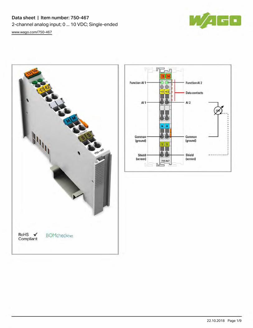
Data sheet | Item number: 750-4672-channel analog input; 0 ... 10 VDC; Single-endedwww.wago.com/750-467
22.10.2018 Page /1 9
RoHS .,¡' Compl iant
BOMcheclv.net
fun<;tion Al11---j~~H-- functionAI2
Data contacls
Al1 tf-'-- Al2
CommGn Igffiund) [ground)
Shield Shield .... .... .. [screen) Cscreen}

Data sheet | Item number: 750-467www.wago.com/750-467
22.10.2018 Page /2 9
Item description
The analog input module processes signals of a standard magnitude 0–10V.
The input signal is electrically isolated and is transmitted with a resolution of 12 bits.
The internal system supply powers the module.
The input channels of the module have one common ground potential.
The shield (screen) is directly connected to the DIN rail.
DataTechnical Data
Number of analog inputs 2
Total number of channels (module) 2
Type of signal Voltage
Type of signal voltage DC 0 … 10 V
Sensor connection 2 x (2-conductor)
Input voltage (max.) 35V
Signal characteristic Single-ended
Resolution [bit] 12 Bit

Data sheet | Item number: 750-467www.wago.com/750-467
22.10.2018 Page /3 9
Resolution [bit] 12 Bit
Bit width 2 x 16-bit data; 2 x 8-bit control/status (optional)
Internal resistance 130 kΩ
Conversion time (typ.) 2 ms
Measurement error, reference temperature 25 °C
Measurement error, deviation max. from the upper-range value 0.2 %
Temperature error max. from the upper-range value 0.01 %/K
System supply voltage DC 5 V; via data contacts
Current consumption, system supply (5 V) 60 mA
Isolation 500 V system/supply
Connection data
Connection technology: inputs/outputs 8 x CAGE CLAMP®
Connection type (1) Inputs/Outputs
Solid conductor 0.08 … 2.5 mm² / 28 … 14 AWG
Fine-stranded conductor 0.08 … 2.5 mm² / 28 … 14 AWG
Strip length 8 … 9 mm / 0.31 … 0.35 Inch
Geometrical Data
Width 12 mm / 0.472 inch
Height 69.8 mm / 2.748 inch
Height from upper-edge of DIN-35 rail 62.6 mm / 2.465 inch
Depth 100 mm / 3.937 inch
Mechanical data
Type of mounting DIN-35 rail
Material Data
Color light gray
Housing material Polycarbonate, polyamide 6.6
Weight 47.613 g
Conformity marking CE
Environmental Requirements
Surrounding air (operating) temperature 0 … 55 °C
Surrounding air (storage) temperature -40 … 85 °C
Degree of protection IP20
Degree of pollution (5) 2 per IEC 61131-2
Operating altitude 0 … 2000 m
Mounting position horizontal (standing/lying) or vertical

Data sheet | Item number: 750-467www.wago.com/750-467
22.10.2018 Page /4 9
Mounting position horizontal (standing/lying) or vertical
Relative air humidity (no condensation) 95 %
Vibration resistance acc. to IEC 60068-2-6
Shock resistance 15g per IEC 60068-2-27
EMC immunity to interference acc. to EN 61000-6-2
EMC emission of interference acc. to EN 61000-6-4
Exposure to pollutants Per IEC 60068-2-42 and IEC 60068-2-43
Permissible H S contaminant concentration at a relative humidity < 2
75 %
10 ppm
Permissible SO contaminant concentration at a relative humidity < 2
75 %
25 ppm
Commercial data
Country of rigin DE
GTIN 4045454392994
Customs Tariff No. 85389099990
Product Group 15 (Remote I/O)
Approvals / Certificates
Ex-Approvals
Logo Approval Certificate name
ATEXTUEV Nord Cert GmbH
TÜV 07 ATEX 554086 X en.
TUEV NordTUEV Nord Cert GmbH
IECEx TUN 09.0001 X
ULUnderwriters Laboratories Inc. (HAZARDOUS LOCATIONS)
E198726 Sec.1 (HAZARDOUS LOCATIONS)
UL-Approvals
Logo Approval Certificate name
ULUL International Netherlands B.V. (ORDINARY LOCATIONS)
E175199 Sec.1 (ORDINARY LOCATIONS)

Data sheet | Item number: 750-467www.wago.com/750-467
22.10.2018 Page /5 9
Compatible productsshield connection
Item no.: 790-108Shield clamping saddle; 11 mm wide; diameter of compatible conductor www.wago.com/790-108
Item no.: 790-116Shield clamping saddle; 19 mm wide; diameter of compatible conductor; 7 ... 16 mm www.wago.com/790-116
Item no.: 790-124Shield clamping saddle; 27 mm wide; diameter of compatible conductor; 6 mm to 24 mm www.wago.com/790-124
Item no.: 790-140Shield clamping saddle; 43 mm wide; diameter of compatible conductor; 22 mm to 40 mm www.wago.com/790-140
Item no.: 790-208Shield clamping saddle; 12.4 mm wide; 3 ... 8 mm www.wago.com/790-208
Item no.: 790-216Shield clamping saddle; 6–16 mm diameter; 21.8 mm wide www.wago.com/790-216
Item no.: 790-220Shield clamping saddle; 6–20 mm diameter; 30 mm wide www.wago.com/790-220
system box
Item no.: 850-804IP65 enclosure; Stainless steel; WxHxD (400x123x200 mm); 4 x M20, 16 x M16, 28 x M12 cable grip www.wago.com/850-804
Item no.: 850-804/000-001IP65 enclosure; Stainless steel; WxHxD (400x123x200 mm); 2 x M20, 13 x M16, 32 x M12 cable grip
www.wago.com/850-804/000-001
Item no.: 850-805IP65 enclosure; Stainless steel; WxHxD (600x123x200 mm); 4 x M20, 19 x M16, 67 x M12 cable grip www.wago.com/850-805
Item no.: 850-814/002-000IP65 enclosure; Sheet steel (RAL 7035); WxHxD (200x120x200 mm); without flange plate
www.wago.com/850-814/002-000
Item no.: 850-815/002-000IP65 enclosure; Sheet steel (RAL 7035); WxHxD (300x120x200 mm); without flange plate
www.wago.com/850-815/002-000
Item no.: 850-816/002-000IP65 enclosure; Sheet steel (RAL 7035); WxHxD (400x120x200 mm); without flange plate
www.wago.com/850-816/002-000
Item no.: 850-817/002-000IP65 enclosure; Sheet steel (RAL 7035); WxHxD (600x120x200 mm); without flange plate
www.wago.com/850-817/002-000
Item no.: 850-825IP65 enclosure; Aluminium (RAL 7032); WxHxD (160x100x160 mm); 9 x M12, 4 x M20 www.wago.com/850-825
Item no.: 850-826IP65 enclosure; Aluminium (RAL 7032); WxHxD (240x100x160 mm); 4 x M20, 4 x M16, 14 x M12 cable
grip
www.wago.com/850-826

Data sheet | Item number: 750-467www.wago.com/750-467
22.10.2018 Page /6 9
grip
Item no.: 850-826/002-000IP65 enclosure; Aluminium (RAL 7035); WxHxD (240x100x160 mm); 4 x M20, 4 x M16, 14 x M12 cable grip
www.wago.com/850-826/002-000
Item no.: 850-827IP65 enclosure; Aluminium (RAL 7032); WxHxD (320x100x160 mm); 4 x M20, 8 x M16, 17 x M12 cable grip
www.wago.com/850-827
Item no.: 850-827/002-000IP65 enclosure; Aluminium (RAL 7035); WxHxD (320x100x160 mm); 4 x M20, 8 x M16, 17 x M12 cable grip
www.wago.com/850-827/002-000
Item no.: 850-828IP65 enclosure; Aluminium (RAL 7032); WxHxD (480x100x160 mm); 4 x M20, 10 x M16, 35 x M12 cable grip
www.wago.com/850-828
Item no.: 850-828/002-000IP65 enclosure; Aluminium (RAL 7035); WxHxD (480x100x160 mm); 4 x M20, 10 x M16, 35 x M12 cable grip
www.wago.com/850-828/002-000
Item no.: 850-834IP65 enclosure; Polyester (RAL 7032); WxHxD (164x100x164 mm); 9 x M12, 4 x M20 www.wago.com/850-834
Item no.: 850-835IP65 enclosure; Polyester (RAL 7032); WxHxD (244x100x164 mm); 4 x M20, 4 x M16, 14 x M12 cable grip
www.wago.com/850-835
Item no.: 850-836IP65 enclosure; Polyester (RAL 7032); WxHxD (324x100x164 mm); 4 x M20, 8 x M16, 17 x M12 cable grip
www.wago.com/850-836
Marking accessories
Item no.: 2009-145Mini-WSB Inline; for smartPRINTER; on reel; stretchable 5 - 5.2 mm; plain; snap-on type www.wago.com/2009-145
Item no.: 2009-145/000-002Mini-WSB Inline; for smartPRINTER; on reel; stretchable 5 - 5.2 mm; plain; snap-on type
www.wago.com/2009-145/000-002
Item no.: 2009-145/000-005Mini-WSB Inline; for smartPRINTER; on reel; stretchable 5 - 5.2 mm; plain; snap-on type
www.wago.com/2009-145/000-005
Item no.: 2009-145/000-006Mini-WSB Inline; for smartPRINTER; on reel; stretchable 5 - 5.2 mm; plain; snap-on type
www.wago.com/2009-145/000-006
Item no.: 2009-145/000-007Mini-WSB Inline; plain; 1,700 Mini-WSB markers (5 mm) on roll; stretchable 5 - 5.2 mm
www.wago.com/2009-145/000-007
Item no.: 2009-145/000-012Mini-WSB Inline; for smartPRINTER; on reel; stretchable 5 - 5.2 mm; plain; snap-on type
www.wago.com/2009-145/000-012
Item no.: 2009-145/000-023

Data sheet | Item number: 750-467www.wago.com/750-467
22.10.2018 Page /7 9
Item no.: 2009-145/000-023Mini-WSB Inline; on reel; stretchable 5 - 5.2 mm; plain; snap-on type www.wago.com/2009-145
/000-023
Item no.: 2009-145/000-024Mini-WSB Inline; on reel; stretchable 5 - 5.2 mm; plain; snap-on type
www.wago.com/2009-145/000-024
Item no.: 248-501Miniature WSB Quick marking system; plain; Marker width 5 mm; 10 strips with 10 markers per card www.wago.com/248-501
Item no.: 248-501/000-002Mini-WSB marking card; as card; not stretchable; plain; snap-on type
www.wago.com/248-501/000-002
Item no.: 248-501/000-005Mini-WSB marking card; as card; plain; snap-on type
www.wago.com/248-501/000-005
Item no.: 248-501/000-006Mini-WSB marking card; as card; not stretchable; plain; snap-on type
www.wago.com/248-501/000-006
Item no.: 248-501/000-007Mini-WSB marking card; as card; not stretchable; plain; snap-on type
www.wago.com/248-501/000-007
Item no.: 248-501/000-012Mini-WSB marking card; as card; not stretchable; plain; snap-on type
www.wago.com/248-501/000-012
Item no.: 248-501/000-017Mini-WSB marking card; as card; not stretchable; plain; snap-on type
www.wago.com/248-501/000-017
Item no.: 248-501/000-023Mini-WSB marking card; as card; not stretchable; plain; snap-on type
www.wago.com/248-501/000-023
Item no.: 248-501/000-024Mini-WSB marking card; as card; not stretchable; plain; snap-on type
www.wago.com/248-501/000-024
Item no.: 750-100Marker card; as a DIN A4 sheet; plain www.wago.com/750-100
Item no.: 750-103Group marker carrier www.wago.com/750-103
Item no.: 750-106Group marker carrier www.wago.com/750-106
Carrier rail
Item no.: 210-112Steel carrier rail; 35 x 7.5 mm; 1 mm thick; 2 m long; slotted; according to EN 60715; "Hole width 25 mm www.wago.com/210-112
Item no.: 210-113
Steel carrier rail; 35 x 7.5 mm; 1 mm thick; 2 m long; unslotted; according to EN 60715 www.wago.com/210-113

Data sheet | Item number: 750-467www.wago.com/750-467
22.10.2018 Page /8 9
Steel carrier rail; 35 x 7.5 mm; 1 mm thick; 2 m long; unslotted; according to EN 60715 www.wago.com/210-113
Item no.: 210-114Steel carrier rail; 35 x 15 mm; 1.5 mm thick; 2 m long; unslotted; similar to EN 60715 www.wago.com/210-114
Item no.: 210-115Steel carrier rail; 35 x 7.5 mm; 1 mm thick; 2 m long; slotted; according to EN 60715; "Hole width 18 mm www.wago.com/210-115
Item no.: 210-118Steel carrier rail; 35 x 15 mm; 2.3 mm thick; 2 m long; unslotted; according to EN 60715 www.wago.com/210-118
Item no.: 210-196Aluminum carrier rail; 35 x 8.2 mm; 1.6 mm thick; 2 m long; unslotted; similar to EN 60715 www.wago.com/210-196
Item no.: 210-197Steel carrier rail; 35 x 15 mm; 1.5 mm thick; 2 m long; slotted; similar to EN 60715 www.wago.com/210-197
Item no.: 210-198Copper carrier rail; 35 x 15 mm; 2.3 mm thick; 2 m long; unslotted; according to EN 60715 www.wago.com/210-198
Item no.: 210-504Steel carrier rail; 35 x 7.5 mm; 1 mm thick; 2 m long; slotted; galvanized; according to EN 60715 www.wago.com/210-504
Item no.: 210-505Steel carrier rail; 35 x 7.5 mm; 1 mm thick; 2 m long; unslotted; galvanized; according to EN 60715 www.wago.com/210-505
Item no.: 210-506Steel carrier rail; 35 x 15 mm; 1.5 mm thick; 2 m long; unslotted; galvanized; similar to EN 60715 www.wago.com/210-506
Item no.: 210-508Steel carrier rail; 35 x 15 mm; 1.5 mm thick; 2 m long; slotted; galvanized; similar to EN 60715 www.wago.com/210-508
DownloadsDocumentation
Manual
2-channel, 0-10VDC, single-ended 06-ene-20152.0 MB
Download
Bid Text
750-467IO-Klemmen
20-ene-2016 DOC28.2 kB
Download
System Description
750/753 Series I/O-System ‒ General Product Information 29-may-20182.0 MB
Download
Use in Hazardous EnvironmentsTerm definition, marking and installation regulations
08-may-20141.0 MB
Download
Overview on WAGO-I/O-SYSTEM 750 approvals 06-jun-2017 Download

Data sheet | Item number: 750-467www.wago.com/750-467
22.10.2018 Page /9 9
Subject to changes.
WAGO Kontakttechnik GmbH & Co. KG Hansastr. 27 32423 Minden Phone: +49571 887-0 | Fax: +49571 887-169 Email: [email protected] | Web: www.wago.com
Do you have any questions about our products? We are always happy to take your call at +49 (571) 887-44222.
Overview on WAGO-I/O-SYSTEM 750 approvals 06-jun-2017314.9 kB
Download
Design NotesBasic conditions and recommendations for higher operational safety
03-may-20111.5 MB
Download
smartDATA
CAD data
3D Download 750-467 URL Download
Device Files
Device Driver
WAGO USB Service Cable Driver / 750 and 857 Series 6.5.3.010-sep-2014
ZIP4.8 MB
Download
Product family
750/753 Series I/O-SystemShow all products from the family.

Data sheet | Item number: 750-4594-channel analog input; 0 ... 10 VDC; Single-endedwww.wago.com/750-459
22.10.2018 Page /1 9
RoHS .,¡' Compl iant
-
BOMcheclv.net
Fehler Al , Al3
Al ,
",'"
Al3
, ",'"
Fehler Al, Al<
Oatenkontakte
Al,
}? M,,,.
Al,
}J "M~
l eistufl!lskontakte

Data sheet | Item number: 750-459www.wago.com/750-459
22.10.2018 Page /2 9
Item description
The analog input module processes signals of a standard magnitude 0–10V.
The input signal is electrically isolated and is transmitted with a resolution of 12 bits.
The internal system supply powers the module.
The input channels of the module have one common ground potential.
DataTechnical Data
Number of analog inputs 4
Total number of channels (module) 4
Type of signal Voltage
Type of signal voltage DC 0 … 10 V
Sensor connection 4 x (2-conductor)
Input voltage (max.) ±40 V
Signal characteristic Single-ended
Resolution [bit] 12 Bit
Bit width 4 x 16-bit data; 4 x 8-bit control/status (optional)

Data sheet | Item number: 750-459www.wago.com/750-459
22.10.2018 Page /3 9
Bit width 4 x 16-bit data; 4 x 8-bit control/status (optional)
Internal resistance 100 kΩ
Conversion time (typ.) 10 ms
Measurement error, reference temperature 25 °C
Measurement error, deviation max. from the upper-range value 0.1 %
Temperature error max. from the upper-range value 0.01 %/K
Field supply voltage DC 24 V (-25 … 30 %); über Leistungskontakte; zur Weiterleitung getunnelt
System supply voltage DC 5 V; via data contacts
Current consumption, system supply (5 V) 65 mA
Isolation 500 V system/supply
Number of incoming power jumper contacts 2
Number of outgoing power jumper contacts 2
Connection data
Connection technology: inputs/outputs 8 x CAGE CLAMP®
Connection type (1) Inputs/Outputs
Solid conductor 0.08 … 2.5 mm² / 28 … 14 AWG
Fine-stranded conductor 0.08 … 2.5 mm² / 28 … 14 AWG
Strip length 8 … 9 mm / 0.31 … 0.35 Inch
Geometrical Data
Width 12 mm / 0.472 inch
Height 69.8 mm / 2.748 inch
Height from upper-edge of DIN-35 rail 62.6 mm / 2.465 inch
Depth 100 mm / 3.937 inch
Mechanical data
Type of mounting DIN-35 rail
Material Data
Color light gray
Housing material Polycarbonate, polyamide 6.6
Fire load 1.504 MJ
Weight 50.826 g
Conformity marking CE
Environmental Requirements
Surrounding air (operating) temperature 0 … 55 °C
Surrounding air (storage) temperature -40 … 85 °C
Degree of protection IP20

Data sheet | Item number: 750-459www.wago.com/750-459
22.10.2018 Page /4 9
Degree of protection IP20
Degree of pollution (5) 2 per IEC 61131-2
Operating altitude 0 … 2000 m
Mounting position horizontal (standing/lying) or vertical
Relative air humidity (no condensation) 95 %
Vibration resistance 4g per IEC 60068-2-6
Shock resistance 15g per IEC 60068-2-27
EMC immunity to interference acc. to EN 61000-6-2, marine applications
EMC emission of interference acc. to EN 61000-6-4, marine applications
Exposure to pollutants Per IEC 60068-2-42 and IEC 60068-2-43
Permissible H S contaminant concentration at a relative humidity < 2
75 %
10 ppm
Permissible SO contaminant concentration at a relative humidity < 2
75 %
25 ppm
Commercial data
Country of rigin DE
GTIN 4045454471507
Customs Tariff No. 85389099990
Product Group 15 (Remote I/O)
Approvals / Certificates
Ship Approvals
Logo Approval Certificate name
DNV GLDet Norske Veritas, Germanischer Lloyd
TAA0000194
DNVDNV Germany GmbH
A-14093
Compatible productsCarrier rail
Item no.: 210-112Steel carrier rail; 35 x 7.5 mm; 1 mm thick; 2 m long; slotted; according to EN 60715; "Hole width 25 mm www.wago.com/210-112
Item no.: 210-113Steel carrier rail; 35 x 7.5 mm; 1 mm thick; 2 m long; unslotted; according to EN 60715 www.wago.com/210-113
Item no.: 210-114Steel carrier rail; 35 x 15 mm; 1.5 mm thick; 2 m long; unslotted; similar to EN 60715 www.wago.com/210-114
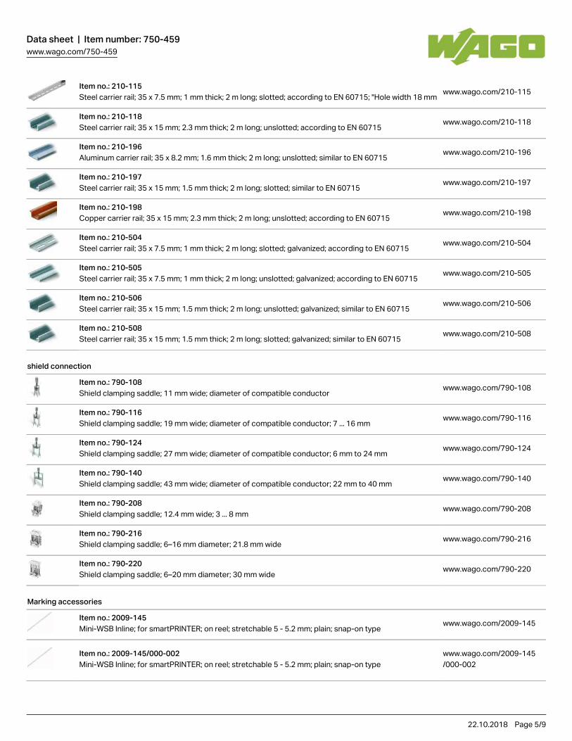
Data sheet | Item number: 750-459www.wago.com/750-459
22.10.2018 Page /5 9
Item no.: 210-115Steel carrier rail; 35 x 7.5 mm; 1 mm thick; 2 m long; slotted; according to EN 60715; "Hole width 18 mm www.wago.com/210-115
Item no.: 210-118Steel carrier rail; 35 x 15 mm; 2.3 mm thick; 2 m long; unslotted; according to EN 60715 www.wago.com/210-118
Item no.: 210-196Aluminum carrier rail; 35 x 8.2 mm; 1.6 mm thick; 2 m long; unslotted; similar to EN 60715 www.wago.com/210-196
Item no.: 210-197Steel carrier rail; 35 x 15 mm; 1.5 mm thick; 2 m long; slotted; similar to EN 60715 www.wago.com/210-197
Item no.: 210-198Copper carrier rail; 35 x 15 mm; 2.3 mm thick; 2 m long; unslotted; according to EN 60715 www.wago.com/210-198
Item no.: 210-504Steel carrier rail; 35 x 7.5 mm; 1 mm thick; 2 m long; slotted; galvanized; according to EN 60715 www.wago.com/210-504
Item no.: 210-505Steel carrier rail; 35 x 7.5 mm; 1 mm thick; 2 m long; unslotted; galvanized; according to EN 60715 www.wago.com/210-505
Item no.: 210-506Steel carrier rail; 35 x 15 mm; 1.5 mm thick; 2 m long; unslotted; galvanized; similar to EN 60715 www.wago.com/210-506
Item no.: 210-508Steel carrier rail; 35 x 15 mm; 1.5 mm thick; 2 m long; slotted; galvanized; similar to EN 60715 www.wago.com/210-508
shield connection
Item no.: 790-108Shield clamping saddle; 11 mm wide; diameter of compatible conductor www.wago.com/790-108
Item no.: 790-116Shield clamping saddle; 19 mm wide; diameter of compatible conductor; 7 ... 16 mm www.wago.com/790-116
Item no.: 790-124Shield clamping saddle; 27 mm wide; diameter of compatible conductor; 6 mm to 24 mm www.wago.com/790-124
Item no.: 790-140Shield clamping saddle; 43 mm wide; diameter of compatible conductor; 22 mm to 40 mm www.wago.com/790-140
Item no.: 790-208Shield clamping saddle; 12.4 mm wide; 3 ... 8 mm www.wago.com/790-208
Item no.: 790-216Shield clamping saddle; 6–16 mm diameter; 21.8 mm wide www.wago.com/790-216
Item no.: 790-220Shield clamping saddle; 6–20 mm diameter; 30 mm wide www.wago.com/790-220
Marking accessories
Item no.: 2009-145Mini-WSB Inline; for smartPRINTER; on reel; stretchable 5 - 5.2 mm; plain; snap-on type www.wago.com/2009-145
Item no.: 2009-145/000-002Mini-WSB Inline; for smartPRINTER; on reel; stretchable 5 - 5.2 mm; plain; snap-on type
www.wago.com/2009-145/000-002
Item no.: 2009-145/000-005

Data sheet | Item number: 750-459www.wago.com/750-459
22.10.2018 Page /6 9
Item no.: 2009-145/000-005Mini-WSB Inline; for smartPRINTER; on reel; stretchable 5 - 5.2 mm; plain; snap-on type
www.wago.com/2009-145/000-005
Item no.: 2009-145/000-006Mini-WSB Inline; for smartPRINTER; on reel; stretchable 5 - 5.2 mm; plain; snap-on type
www.wago.com/2009-145/000-006
Item no.: 2009-145/000-007Mini-WSB Inline; plain; 1,700 Mini-WSB markers (5 mm) on roll; stretchable 5 - 5.2 mm
www.wago.com/2009-145/000-007
Item no.: 2009-145/000-012Mini-WSB Inline; for smartPRINTER; on reel; stretchable 5 - 5.2 mm; plain; snap-on type
www.wago.com/2009-145/000-012
Item no.: 2009-145/000-023Mini-WSB Inline; on reel; stretchable 5 - 5.2 mm; plain; snap-on type
www.wago.com/2009-145/000-023
Item no.: 2009-145/000-024Mini-WSB Inline; on reel; stretchable 5 - 5.2 mm; plain; snap-on type
www.wago.com/2009-145/000-024
Item no.: 248-501Miniature WSB Quick marking system; plain; Marker width 5 mm; 10 strips with 10 markers per card www.wago.com/248-501
Item no.: 248-501/000-002Mini-WSB marking card; as card; not stretchable; plain; snap-on type
www.wago.com/248-501/000-002
Item no.: 248-501/000-005Mini-WSB marking card; as card; plain; snap-on type
www.wago.com/248-501/000-005
Item no.: 248-501/000-006Mini-WSB marking card; as card; not stretchable; plain; snap-on type
www.wago.com/248-501/000-006
Item no.: 248-501/000-007Mini-WSB marking card; as card; not stretchable; plain; snap-on type
www.wago.com/248-501/000-007
Item no.: 248-501/000-012Mini-WSB marking card; as card; not stretchable; plain; snap-on type
www.wago.com/248-501/000-012
Item no.: 248-501/000-017Mini-WSB marking card; as card; not stretchable; plain; snap-on type
www.wago.com/248-501/000-017
Item no.: 248-501/000-023Mini-WSB marking card; as card; not stretchable; plain; snap-on type
www.wago.com/248-501/000-023
Item no.: 248-501/000-024Mini-WSB marking card; as card; not stretchable; plain; snap-on type
www.wago.com/248-501/000-024
Item no.: 750-100

Data sheet | Item number: 750-459www.wago.com/750-459
22.10.2018 Page /7 9
Item no.: 750-100Marker card; as a DIN A4 sheet; plain
www.wago.com/750-100
Item no.: 750-103Group marker carrier www.wago.com/750-103
Item no.: 750-106Group marker carrier www.wago.com/750-106
system box
Item no.: 850-804IP65 enclosure; Stainless steel; WxHxD (400x123x200 mm); 4 x M20, 16 x M16, 28 x M12 cable grip www.wago.com/850-804
Item no.: 850-804/000-001IP65 enclosure; Stainless steel; WxHxD (400x123x200 mm); 2 x M20, 13 x M16, 32 x M12 cable grip
www.wago.com/850-804/000-001
Item no.: 850-805IP65 enclosure; Stainless steel; WxHxD (600x123x200 mm); 4 x M20, 19 x M16, 67 x M12 cable grip www.wago.com/850-805
Item no.: 850-814/002-000IP65 enclosure; Sheet steel (RAL 7035); WxHxD (200x120x200 mm); without flange plate
www.wago.com/850-814/002-000
Item no.: 850-815/002-000IP65 enclosure; Sheet steel (RAL 7035); WxHxD (300x120x200 mm); without flange plate
www.wago.com/850-815/002-000
Item no.: 850-816/002-000IP65 enclosure; Sheet steel (RAL 7035); WxHxD (400x120x200 mm); without flange plate
www.wago.com/850-816/002-000
Item no.: 850-817/002-000IP65 enclosure; Sheet steel (RAL 7035); WxHxD (600x120x200 mm); without flange plate
www.wago.com/850-817/002-000
Item no.: 850-825IP65 enclosure; Aluminium (RAL 7032); WxHxD (160x100x160 mm); 9 x M12, 4 x M20 www.wago.com/850-825
Item no.: 850-826IP65 enclosure; Aluminium (RAL 7032); WxHxD (240x100x160 mm); 4 x M20, 4 x M16, 14 x M12 cable grip
www.wago.com/850-826
Item no.: 850-826/002-000IP65 enclosure; Aluminium (RAL 7035); WxHxD (240x100x160 mm); 4 x M20, 4 x M16, 14 x M12 cable grip
www.wago.com/850-826/002-000
Item no.: 850-827IP65 enclosure; Aluminium (RAL 7032); WxHxD (320x100x160 mm); 4 x M20, 8 x M16, 17 x M12 cable grip
www.wago.com/850-827
Item no.: 850-827/002-000IP65 enclosure; Aluminium (RAL 7035); WxHxD (320x100x160 mm); 4 x M20, 8 x M16, 17 x M12 cable grip
www.wago.com/850-827/002-000
Item no.: 850-828IP65 enclosure; Aluminium (RAL 7032); WxHxD (480x100x160 mm); 4 x M20, 10 x M16, 35 x M12 cable grip
www.wago.com/850-828
Item no.: 850-828/002-000 www.wago.com/850-828

Data sheet | Item number: 750-459www.wago.com/750-459
22.10.2018 Page /8 9
Item no.: 850-828/002-000IP65 enclosure; Aluminium (RAL 7035); WxHxD (480x100x160 mm); 4 x M20, 10 x M16, 35 x M12 cable grip
www.wago.com/850-828/002-000
Item no.: 850-834IP65 enclosure; Polyester (RAL 7032); WxHxD (164x100x164 mm); 9 x M12, 4 x M20 www.wago.com/850-834
Item no.: 850-835IP65 enclosure; Polyester (RAL 7032); WxHxD (244x100x164 mm); 4 x M20, 4 x M16, 14 x M12 cable grip
www.wago.com/850-835
Item no.: 850-836IP65 enclosure; Polyester (RAL 7032); WxHxD (324x100x164 mm); 4 x M20, 8 x M16, 17 x M12 cable grip
www.wago.com/850-836
DownloadsDocumentation
Manual
4-channel, 0-10VDC, single-ended 25-nov-20152.0 MB
Download
Bid Text
750-459IO-Klemmen
20-ene-2016 DOC29.2 kB
Download
System Description
Use in Hazardous EnvironmentsTerm definition, marking and installation regulations
08-may-20141.0 MB
Download
750/753 Series I/O-System ‒ General Product Information 29-may-20182.0 MB
Download
Overview on WAGO-I/O-SYSTEM 750 approvals 06-jun-2017314.9 kB
Download
Design NotesBasic conditions and recommendations for higher operational safety
03-may-20111.5 MB
Download
smartDATA
CAD data
3D Download 750-459 URL Download

Data sheet | Item number: 750-459www.wago.com/750-459
22.10.2018 Page /9 9
Subject to changes.
WAGO Kontakttechnik GmbH & Co. KG Hansastr. 27 32423 Minden Phone: +49571 887-0 | Fax: +49571 887-169 Email: [email protected] | Web: www.wago.com
Do you have any questions about our products? We are always happy to take your call at +49 (571) 887-44222.
Device Files
Device Driver
WAGO USB Service Cable Driver / 750 and 857 Series 6.5.3.010-sep-2014
ZIP4.8 MB
Download
Product family
750/753 Series I/O-SystemShow all products from the family.

Data sheet | Item number: 750-4518-channel analog input; Resistance measurement; Adjustablewww.wago.com/750-451
22.10.2018 Page /1 10
RoHS .,¡' Compliant
BOMcheckr.net
Status Rl ... R8
.R1
.R2
.RJ
."
.RS
.R6
.R7
·RB
Error R1...R8
Oata contacls
- R1
-R2
-RJ
-" -RS
-R6
-R7
-RB Power jumpercontacts

Data sheet | Item number: 750-451www.wago.com/750-451
22.10.2018 Page /2 10
Item description
The input module directly connects to Pt and Ni resistance sensors.
Two-wire sensors can be connected.
The module automatically linearizes the entire temperature range. A sensor error (short circuit, wire break or out-of-measurement range) is indicated by a red LED. Unused channels can be deactivated.
The module can be configured via WAGO‐I/O‐CHECK or GSD files.
It features multiple setting options and high accuracy.
DataTechnical Data
Number of analog inputs 8
Total number of channels (module) 8
Type of signal Resistance measurementPotentiometer positions
Configurable type of signal yes
Sensor connection 8 x (2-conductor)
Bit width 8 x 16-bit data; 8 x 8-bit control/status (optional)

Data sheet | Item number: 750-451www.wago.com/750-451
22.10.2018 Page /3 10
Bit width 8 x 16-bit data; 8 x 8-bit control/status (optional)
Resolution (over entire range) 0.1 °C (over the entire range); 0.01 °C (-50 °C ... 150 °C; Pt1000, Ni1000)
Conversion time (typ.) 100 ms
Measuring error (25 °C) ≤ ±0.6 K (Pt100, Pt200, Pt500, Ni100, Ni120); ≤ ±0.2 K (Pt1000, Ni1000); ≤ ±0.3 Ω at resistance measurement
Measuring current (typ.) ≤ 350 µA
Response time (max.) 3 s
Sensor types Pt100 (default setting), Pt200, Pt500, Pt1000, Ni 100, Ni 120, Ni 1000 (TK6180 + TK5000), Potentiometer 0 Ohm ... 1.2 kOhm, 0 Ohm ... 5 kOhm
Temperature range -200 … +850 °C (Pt100, Pt200, Pt500, Pt1000), -60 … +250 °C (Ni100, Ni1000), -80 … +260 °C (Ni120)
Field supply voltage DC 24 V (-25 … 30 %); über Leistungskontakte; zur Weiterleitung getunnelt
System supply voltage DC 5 V; via data contacts
Current consumption, system supply (5 V) 110 mA
Isolation 500 V system/supply
Number of incoming power jumper contacts 2
Number of outgoing power jumper contacts 2
Connection data
Connection technology: inputs/outputs 16 x Push-in CAGE CLAMP®
Connection type (1) Inputs/Outputs
Solid conductor 0.08 … 1.5 mm² / 28 … 16 AWG
Fine-stranded conductor 0.25 … 1.5 mm² / 22 … 16 AWG
Strip length 8 … 9 mm / 0.31 … 0.35 Inch
Geometrical Data
Width 12 mm / 0.472 inch
Height 69 mm / 2.717 inch
Height from upper-edge of DIN-35 rail 61.8 mm / 2.433 inch
Depth 100 mm / 3.937 inch
Mechanical data
Type of mounting DIN-35 rail
Material Data
Housing material Polycarbonate, polyamide 6.6
Weight 47.892 g
Conformity marking CE

Data sheet | Item number: 750-451www.wago.com/750-451
22.10.2018 Page /4 10
Environmental Requirements
Surrounding air (operating) temperature 0 … 55 °C
Surrounding air (storage) temperature -40 … 85 °C
Degree of protection IP20
Degree of pollution (5) 2 per IEC 61131-2
Operating altitude 0 … 2000 m
Mounting position horizontal (standing/lying) or vertical
Relative air humidity (no condensation) 95 %
Vibration resistance 4g per IEC 60068-2-6
Shock resistance 15g per IEC 60068-2-27
EMC immunity to interference acc. to EN 61000-6-1, EN 61000-6-2
EMC emission of interference acc. to EN 61000-6-3
Exposure to pollutants Per IEC 60068-2-42 and IEC 60068-2-43
Permissible H S contaminant concentration at a relative humidity < 2
75 %
10 ppm
Permissible SO contaminant concentration at a relative humidity < 2
75 %
25 ppm
Commercial data
Country of rigin DE
GTIN 4017332258388
Customs Tariff No. 85389099990
Approvals / Certificates
Ex-Approvals
Logo Approval Certificate name
ATEXTUEV Nord Cert GmbH
IECEx_TUN_14.0035_X
ATEXTUEV Nord Cert GmbH
TUEV_14_ATEX_148929_X
ULUnderwriters Laboratories Inc. (HAZARDOUS LOCATIONS)
E198726 Sec.1 (HAZARDOUS LOCATIONS)
Ship Approvals
Logo Approval Certificate name
DNV GL
Det Norske Veritas, Germanischer Lloyd
TAA00000Y7 Rev.1

Data sheet | Item number: 750-451www.wago.com/750-451
22.10.2018 Page /5 10
Det Norske Veritas, Germanischer Lloyd
DNV GLDet Norske Veritas, Germanischer Lloyd
TAA00000Y7
DNV GLDet Norske Veritas, Germanischer Lloyd
TAA0000194
DNV GLDet Norske Veritas, Germanischer Lloyd
TAA0000194
UL-Approvals
Logo Approval Certificate name
ULUL International Netherlands B.V. (ORDINARY LOCATIONS)
E175199 Sec.1 (ORDINARY LOCATIONS)
Compatible productstools
Item no.: 210-719Operating tool with partially insulated shaft; Type 1, blade (2.5 x 0.4) mm www.wago.com/210-719
shield connection
Item no.: 790-108Shield clamping saddle; 11 mm wide; diameter of compatible conductor www.wago.com/790-108
Item no.: 790-116Shield clamping saddle; 19 mm wide; diameter of compatible conductor; 7 ... 16 mm www.wago.com/790-116
Item no.: 790-124Shield clamping saddle; 27 mm wide; diameter of compatible conductor; 6 mm to 24 mm www.wago.com/790-124
Item no.: 790-140Shield clamping saddle; 43 mm wide; diameter of compatible conductor; 22 mm to 40 mm www.wago.com/790-140
Item no.: 790-208Shield clamping saddle; 12.4 mm wide; 3 ... 8 mm www.wago.com/790-208
Item no.: 790-216Shield clamping saddle; 6–16 mm diameter; 21.8 mm wide www.wago.com/790-216
Item no.: 790-220Shield clamping saddle; 6–20 mm diameter; 30 mm wide www.wago.com/790-220

Data sheet | Item number: 750-451www.wago.com/750-451
22.10.2018 Page /6 10
Marking accessories
Item no.: 2009-145Mini-WSB Inline; for smartPRINTER; on reel; stretchable 5 - 5.2 mm; plain; snap-on type www.wago.com/2009-145
Item no.: 2009-145/000-002Mini-WSB Inline; for smartPRINTER; on reel; stretchable 5 - 5.2 mm; plain; snap-on type
www.wago.com/2009-145/000-002
Item no.: 2009-145/000-005Mini-WSB Inline; for smartPRINTER; on reel; stretchable 5 - 5.2 mm; plain; snap-on type
www.wago.com/2009-145/000-005
Item no.: 2009-145/000-006Mini-WSB Inline; for smartPRINTER; on reel; stretchable 5 - 5.2 mm; plain; snap-on type
www.wago.com/2009-145/000-006
Item no.: 2009-145/000-007Mini-WSB Inline; plain; 1,700 Mini-WSB markers (5 mm) on roll; stretchable 5 - 5.2 mm
www.wago.com/2009-145/000-007
Item no.: 2009-145/000-012Mini-WSB Inline; for smartPRINTER; on reel; stretchable 5 - 5.2 mm; plain; snap-on type
www.wago.com/2009-145/000-012
Item no.: 2009-145/000-023Mini-WSB Inline; on reel; stretchable 5 - 5.2 mm; plain; snap-on type
www.wago.com/2009-145/000-023
Item no.: 2009-145/000-024Mini-WSB Inline; on reel; stretchable 5 - 5.2 mm; plain; snap-on type
www.wago.com/2009-145/000-024
Item no.: 248-501Miniature WSB Quick marking system; plain; Marker width 5 mm; 10 strips with 10 markers per card www.wago.com/248-501
Item no.: 248-501/000-002Mini-WSB marking card; as card; not stretchable; plain; snap-on type
www.wago.com/248-501/000-002
Item no.: 248-501/000-005Mini-WSB marking card; as card; plain; snap-on type
www.wago.com/248-501/000-005
Item no.: 248-501/000-006Mini-WSB marking card; as card; not stretchable; plain; snap-on type
www.wago.com/248-501/000-006
Item no.: 248-501/000-007Mini-WSB marking card; as card; not stretchable; plain; snap-on type
www.wago.com/248-501/000-007
Item no.: 248-501/000-012Mini-WSB marking card; as card; not stretchable; plain; snap-on type
www.wago.com/248-501/000-012
Item no.: 248-501/000-017

Data sheet | Item number: 750-451www.wago.com/750-451
22.10.2018 Page /7 10
Item no.: 248-501/000-017Mini-WSB marking card; as card; not stretchable; plain; snap-on type www.wago.com/248-501
/000-017
Item no.: 248-501/000-023Mini-WSB marking card; as card; not stretchable; plain; snap-on type
www.wago.com/248-501/000-023
Item no.: 248-501/000-024Mini-WSB marking card; as card; not stretchable; plain; snap-on type
www.wago.com/248-501/000-024
Item no.: 750-103Group marker carrier www.wago.com/750-103
Item no.: 750-107Group marker carrier www.wago.com/750-107
system box
Item no.: 850-804IP65 enclosure; Stainless steel; WxHxD (400x123x200 mm); 4 x M20, 16 x M16, 28 x M12 cable grip www.wago.com/850-804
Item no.: 850-804/000-001IP65 enclosure; Stainless steel; WxHxD (400x123x200 mm); 2 x M20, 13 x M16, 32 x M12 cable grip
www.wago.com/850-804/000-001
Item no.: 850-805IP65 enclosure; Stainless steel; WxHxD (600x123x200 mm); 4 x M20, 19 x M16, 67 x M12 cable grip www.wago.com/850-805
Item no.: 850-814/002-000IP65 enclosure; Sheet steel (RAL 7035); WxHxD (200x120x200 mm); without flange plate
www.wago.com/850-814/002-000
Item no.: 850-815/002-000IP65 enclosure; Sheet steel (RAL 7035); WxHxD (300x120x200 mm); without flange plate
www.wago.com/850-815/002-000
Item no.: 850-816/002-000IP65 enclosure; Sheet steel (RAL 7035); WxHxD (400x120x200 mm); without flange plate
www.wago.com/850-816/002-000
Item no.: 850-817/002-000IP65 enclosure; Sheet steel (RAL 7035); WxHxD (600x120x200 mm); without flange plate
www.wago.com/850-817/002-000
Item no.: 850-825IP65 enclosure; Aluminium (RAL 7032); WxHxD (160x100x160 mm); 9 x M12, 4 x M20 www.wago.com/850-825
Item no.: 850-826IP65 enclosure; Aluminium (RAL 7032); WxHxD (240x100x160 mm); 4 x M20, 4 x M16, 14 x M12 cable grip
www.wago.com/850-826
Item no.: 850-826/002-000IP65 enclosure; Aluminium (RAL 7035); WxHxD (240x100x160 mm); 4 x M20, 4 x M16, 14 x M12 cable grip
www.wago.com/850-826/002-000
Item no.: 850-827IP65 enclosure; Aluminium (RAL 7032); WxHxD (320x100x160 mm); 4 x M20, 8 x M16, 17 x M12 cable
gripwww.wago.com/850-827

Data sheet | Item number: 750-451www.wago.com/750-451
22.10.2018 Page /8 10
grip
Item no.: 850-827/002-000IP65 enclosure; Aluminium (RAL 7035); WxHxD (320x100x160 mm); 4 x M20, 8 x M16, 17 x M12 cable grip
www.wago.com/850-827/002-000
Item no.: 850-828IP65 enclosure; Aluminium (RAL 7032); WxHxD (480x100x160 mm); 4 x M20, 10 x M16, 35 x M12 cable grip
www.wago.com/850-828
Item no.: 850-828/002-000IP65 enclosure; Aluminium (RAL 7035); WxHxD (480x100x160 mm); 4 x M20, 10 x M16, 35 x M12 cable grip
www.wago.com/850-828/002-000
Item no.: 850-834IP65 enclosure; Polyester (RAL 7032); WxHxD (164x100x164 mm); 9 x M12, 4 x M20 www.wago.com/850-834
Item no.: 850-835IP65 enclosure; Polyester (RAL 7032); WxHxD (244x100x164 mm); 4 x M20, 4 x M16, 14 x M12 cable grip
www.wago.com/850-835
Item no.: 850-836IP65 enclosure; Polyester (RAL 7032); WxHxD (324x100x164 mm); 4 x M20, 8 x M16, 17 x M12 cable grip
www.wago.com/850-836
Carrier rail
Item no.: 210-112Steel carrier rail; 35 x 7.5 mm; 1 mm thick; 2 m long; slotted; according to EN 60715; "Hole width 25 mm www.wago.com/210-112
Item no.: 210-113Steel carrier rail; 35 x 7.5 mm; 1 mm thick; 2 m long; unslotted; according to EN 60715 www.wago.com/210-113
Item no.: 210-114Steel carrier rail; 35 x 15 mm; 1.5 mm thick; 2 m long; unslotted; similar to EN 60715 www.wago.com/210-114
Item no.: 210-115Steel carrier rail; 35 x 7.5 mm; 1 mm thick; 2 m long; slotted; according to EN 60715; "Hole width 18 mm www.wago.com/210-115
Item no.: 210-118Steel carrier rail; 35 x 15 mm; 2.3 mm thick; 2 m long; unslotted; according to EN 60715 www.wago.com/210-118
Item no.: 210-196Aluminum carrier rail; 35 x 8.2 mm; 1.6 mm thick; 2 m long; unslotted; similar to EN 60715 www.wago.com/210-196
Item no.: 210-197Steel carrier rail; 35 x 15 mm; 1.5 mm thick; 2 m long; slotted; similar to EN 60715 www.wago.com/210-197
Item no.: 210-198Copper carrier rail; 35 x 15 mm; 2.3 mm thick; 2 m long; unslotted; according to EN 60715 www.wago.com/210-198
Item no.: 210-504Steel carrier rail; 35 x 7.5 mm; 1 mm thick; 2 m long; slotted; galvanized; according to EN 60715 www.wago.com/210-504
Item no.: 210-505Steel carrier rail; 35 x 7.5 mm; 1 mm thick; 2 m long; unslotted; galvanized; according to EN 60715 www.wago.com/210-505
Item no.: 210-506Steel carrier rail; 35 x 15 mm; 1.5 mm thick; 2 m long; unslotted; galvanized; similar to EN 60715 www.wago.com/210-506
Item no.: 210-508

Data sheet | Item number: 750-451www.wago.com/750-451
22.10.2018 Page /9 10
Item no.: 210-508Steel carrier rail; 35 x 15 mm; 1.5 mm thick; 2 m long; slotted; galvanized; similar to EN 60715
www.wago.com/210-508
DownloadsDocumentation
Manual
8 AI RTD, Configurable8-Channel Analog Input Module for Resistance Sensors, Configurable
25-jul-20164.5 MB
Download
Bid Text
750-451 20-ene-2016 DOC31.2 kB
Download
System Description
Design NotesBasic conditions and recommendations for higher operational safety
03-may-20111.5 MB
Download
750/753 Series I/O-System ‒ General Product Information 29-may-20182.0 MB
Download
Use in Hazardous EnvironmentsTerm definition, marking and installation regulations
08-may-20141.0 MB
Download
Overview on WAGO-I/O-SYSTEM 750 approvals 06-jun-2017314.9 kB
Download
Application Notes
Application Note CoDeSys 2.3
Application Note Library ModuleAccess_01These instructions describe the use of the ModuleAccess_01.lib library using 4 examples.
29-ene-20161.0 MB
Download
Libraries
Library
ModuleAccess_01.libThe ModuleAccess_01 library provides both module configuration and access to its process data within a CoDeSys project without the use of WAGO I/O Check.
16-feb-20181.5 MB
Download
smartDATA

Data sheet | Item number: 750-451www.wago.com/750-451
22.10.2018 Page /10 10
Subject to changes.
WAGO Kontakttechnik GmbH & Co. KG Hansastr. 27 32423 Minden Phone: +49571 887-0 | Fax: +49571 887-169 Email: [email protected] | Web: www.wago.com
Do you have any questions about our products? We are always happy to take your call at +49 (571) 887-44222.
smartDATA
CAD data
3D Download 750-451 URL Download
Product family
750/753 Series I/O-SystemShow all products from the family.

Data sheet | Item number: 750-352Fieldbus Coupler ETHERNET; 3rd Generationwww.wago.com/750-352
22.10.2018 Page /1 12
RoHS .,¡' Compl iant
BOMcheckr.net
•• s -
--l """ '" " Fialdbus -".n ..... tiro
'N' ,~~ -_ "o RH 5
u .. kingo,..
~I l1>aI/l [] ':1" t--- St>IlJIinditolioo
a - l:'f' .~-
t ·' -_nodo ... t---.- --H.OIO D I'<> O
~JI! l,fI] fI] O Conr>ilUllIioo in!arIa<:a
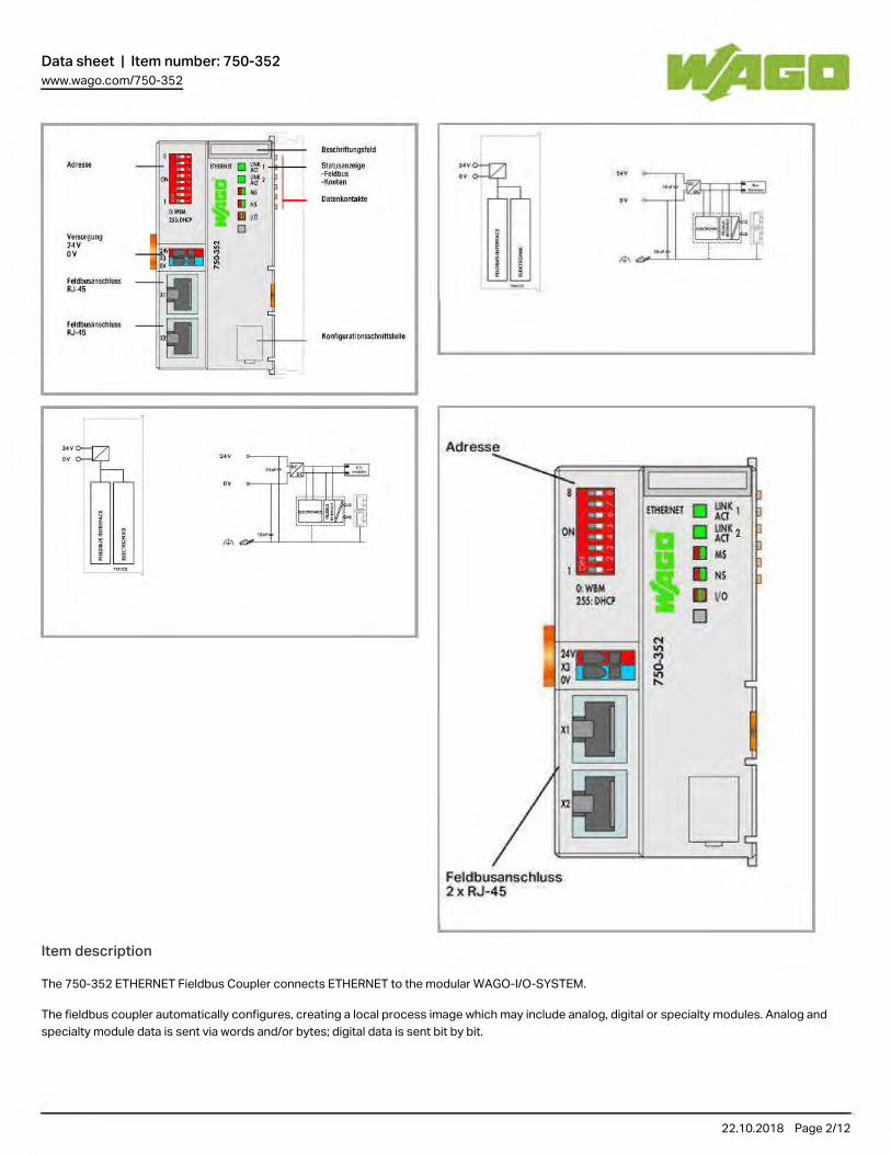
Data sheet | Item number: 750-352www.wago.com/750-352
22.10.2018 Page /2 12
Item description
The 750‐352 ETHERNET Fieldbus Coupler connects ETHERNET to the modular WAGO‐I/O‐SYSTEM.
The fieldbus coupler automatically configures, creating a local process image which may include analog, digital or specialty modules. Analog and specialty module data is sent via words and/or bytes; digital data is sent bit by bit.
Two ETHERNET interfaces and an integrated switch allow the fieldbus to be wired in a line topology. This eliminates additional network devices such
.,- - ~I m-n ~ ~ ,
. '''' ' a .: 1 m.. .- H ~n "'- o ~'''''''l1lfl9
! '" ~-.. ---¡
~:--w _ j{1] ~w _ I lJ
::'~ ", -"
, •
llillJJ ..
~
, ti
801l<~illuogs!old
r------ ~ -l\0'00i.,
r ¡¡m.,,,,, ... 1:te
IlooIlguroO .......... lnSlelle
. 1L iD IM: ~
, i !
Feldbusanschluss 2x RJ·45
o Q 11 .. 11 ..
v. O

Data sheet | Item number: 750-352www.wago.com/750-352
22.10.2018 Page /3 12
Two ETHERNET interfaces and an integrated switch allow the fieldbus to be wired in a line topology. This eliminates additional network devices such as switches or hubs. Both interfaces support Auto‐Negotiation and Auto‐MDI(X).
The DIP switch configures the last byte of the IP address and may be used for IP address assignment (DHCP, BootP, static).
The coupler is designed for fieldbus communication in both Ethernet/IP and MODBUS networks. It also supports a wide variety of standard ETHERNET protocols (e.g., HTTP, BootP, DHCP, DNS, SNMP, FTP).
An integrated Web server provides configuration and status information to the coupler.
The coupler has an integrated supply terminal for the system voltage. The field power jumper contacts are supplied via a separate supply module.
DataTechnical Data
Communication EtherNet/IPModbus TCPEthernet
Ethernet protocol HTTPBootPDHCPDNSFTPSNMP
Baud rate 10/100Mbit/s
Transmission medium Twisted Pair S-UTP; 100 Ω; Cat. 5; Line length (max.): 100 m
Transmission performance Class D acc. to EN 50173
Number of modules per node max. 250
Number of I/O modules without bus extension max. 64
Max. input and output process image (fieldbus) 1020Words/1020Words
System supply voltage DC 24 V (−25 … +30 %); via wiring level
Current consumption, system supply (5 V) 450 mA
Total current for system supply 700 mA
Input current typ. at rated load (24 V) 280 mA
Efficiency of the power supply (typ.) at nominal load (24 V) 90 %
Isolation 500 V system/supply
Connection data
Connection technology: communication/fieldbus EtherNet/IP: 2 x RJ-45; Modbus TCP/UDP: 2 x RJ-45
Connection technology: system supply 2 x CAGE CLAMP®
Connection technology: device configuration 1 x 4-pole male connector
Connection type (1) Systemversorgung
Solid conductor 0.08 … 1.5 mm² / 28 … 14 AWG
Fine-stranded conductor 0.08 … 1.5 mm² / 28 … 14 AWG
Strip length 5 … 6 mm / 0.2 … 0.24 Inch
Geometrical Data

Data sheet | Item number: 750-352www.wago.com/750-352
22.10.2018 Page /4 12
Geometrical Data
Width 49.5 mm / 1.949 inch
Height 71.9 mm / 2.831 inch
Height from upper-edge of DIN-35 rail 64.7 mm / 2.547 inch
Depth 96.8 mm / 3.811 inch
Mechanical data
Type of mounting DIN-35 rail
Material Data
Color lichtgrau
Housing material Polycarbonate, polyamide 6.6
Weight 108.5 g
Conformity marking CE
Environmental Requirements
Surrounding air (operating) temperature 0 … 55 °C
Surrounding air (storage) temperature -40 … 85 °C
Degree of protection IP20
Degree of pollution (5) 2 per IEC 61131-2
Operating altitude 0 … 2000 m
Mounting position horizontal (standing/lying) or vertical
Relative air humidity (no condensation) 95 %
Vibration resistance 4g per IEC 60068-2-6
Shock resistance 15g per IEC 60068-2-27
EMC immunity to interference acc. to EN 61000-6-2, marine applications
EMC emission of interference acc. to EN 61000-6-3, marine applications
Exposure to pollutants Per IEC 60068-2-42 and IEC 60068-2-43
Permissible H S contaminant concentration at a relative humidity < 2
75 %
10 ppm
Permissible SO contaminant concentration at a relative humidity < 2
75 %
25 ppm
Commercial data
Country of rigin DE
GTIN 4050821086840
Customs Tariff No. 85176200000
Product Group 15 (Remote I/O)
Approvals / Certificates

Data sheet | Item number: 750-352www.wago.com/750-352
22.10.2018 Page /5 12
Approvals / Certificates
Ex-Approvals
Logo Approval Certificate name
ATEXTUEV Nord Cert GmbH
TÜV 07 ATEX 554086 X en.
TUEV NordTUEV Nord Cert GmbH
IECEx TUN 09.0001 X
ULUnderwriters Laboratories Inc. (HAZARDOUS LOCATIONS)
E198726 Sec.1 (HAZARDOUS LOCATIONS)
Ship Approvals
Logo Approval Certificate name
ABSAmerican Bureau of Shipping
16-HG1554285-PDA
BVBureau Veritas S.A.
30389/B0 BV
DNVDNV Germany GmbH
A-14093
GLGermanischer Lloyd
11 631 - 10 HH
KRKorean Register of Shipping
HMB05880-AC001
LR{Lloyds Register EMEA
02/20026 (E5)
NKNippon Kaiji Kyokai
TA17255M
PRSPolski Rejetr Statkow
TE/1989/880590/13

Data sheet | Item number: 750-352www.wago.com/750-352
22.10.2018 Page /6 12
RINARINA Germany GmbH
ELE134212XG
UL-Approvals
Logo Approval Certificate name
ULUL International Netherlands B.V. (ORDINARY LOCATIONS)
E175199 Sec.1 (ORDINARY LOCATIONS)
Compatible productsCarrier rail
Item no.: 210-112Steel carrier rail; 35 x 7.5 mm; 1 mm thick; 2 m long; slotted; according to EN 60715; "Hole width 25 mm www.wago.com/210-112
Item no.: 210-113Steel carrier rail; 35 x 7.5 mm; 1 mm thick; 2 m long; unslotted; according to EN 60715 www.wago.com/210-113
Item no.: 210-114Steel carrier rail; 35 x 15 mm; 1.5 mm thick; 2 m long; unslotted; similar to EN 60715 www.wago.com/210-114
Item no.: 210-115Steel carrier rail; 35 x 7.5 mm; 1 mm thick; 2 m long; slotted; according to EN 60715; "Hole width 18 mm www.wago.com/210-115
Item no.: 210-118Steel carrier rail; 35 x 15 mm; 2.3 mm thick; 2 m long; unslotted; according to EN 60715 www.wago.com/210-118
Item no.: 210-196Aluminum carrier rail; 35 x 8.2 mm; 1.6 mm thick; 2 m long; unslotted; similar to EN 60715 www.wago.com/210-196
Item no.: 210-197Steel carrier rail; 35 x 15 mm; 1.5 mm thick; 2 m long; slotted; similar to EN 60715 www.wago.com/210-197
Item no.: 210-198Copper carrier rail; 35 x 15 mm; 2.3 mm thick; 2 m long; unslotted; according to EN 60715 www.wago.com/210-198
Item no.: 210-504Steel carrier rail; 35 x 7.5 mm; 1 mm thick; 2 m long; slotted; galvanized; according to EN 60715 www.wago.com/210-504
Item no.: 210-505Steel carrier rail; 35 x 7.5 mm; 1 mm thick; 2 m long; unslotted; galvanized; according to EN 60715 www.wago.com/210-505
Item no.: 210-506Steel carrier rail; 35 x 15 mm; 1.5 mm thick; 2 m long; unslotted; galvanized; similar to EN 60715 www.wago.com/210-506
Item no.: 210-508Steel carrier rail; 35 x 15 mm; 1.5 mm thick; 2 m long; slotted; galvanized; similar to EN 60715 www.wago.com/210-508

Data sheet | Item number: 750-352www.wago.com/750-352
22.10.2018 Page /7 12
shield connection
Item no.: 790-108Shield clamping saddle; 11 mm wide; diameter of compatible conductor www.wago.com/790-108
Item no.: 790-116Shield clamping saddle; 19 mm wide; diameter of compatible conductor; 7 ... 16 mm www.wago.com/790-116
Item no.: 790-124Shield clamping saddle; 27 mm wide; diameter of compatible conductor; 6 mm to 24 mm www.wago.com/790-124
Item no.: 790-140Shield clamping saddle; 43 mm wide; diameter of compatible conductor; 22 mm to 40 mm www.wago.com/790-140
Item no.: 790-208Shield clamping saddle; 12.4 mm wide; 3 ... 8 mm www.wago.com/790-208
Item no.: 790-216Shield clamping saddle; 6–16 mm diameter; 21.8 mm wide www.wago.com/790-216
Item no.: 790-220Shield clamping saddle; 6–20 mm diameter; 30 mm wide www.wago.com/790-220
General accessories
Item no.: 750-921Bluetooth® Adapter www.wago.com/750-921
Item no.: 750-923Configuration cable; USB connector www.wago.com/750-923
Item no.: 750-923/000-001Configuration cable; USB connector
www.wago.com/750-923/000-001
Marking accessories
Item no.: 2009-145Mini-WSB Inline; for smartPRINTER; on reel; stretchable 5 - 5.2 mm; plain; snap-on type www.wago.com/2009-145
Item no.: 2009-145/000-002Mini-WSB Inline; for smartPRINTER; on reel; stretchable 5 - 5.2 mm; plain; snap-on type
www.wago.com/2009-145/000-002
Item no.: 2009-145/000-005Mini-WSB Inline; for smartPRINTER; on reel; stretchable 5 - 5.2 mm; plain; snap-on type
www.wago.com/2009-145/000-005
Item no.: 2009-145/000-006Mini-WSB Inline; for smartPRINTER; on reel; stretchable 5 - 5.2 mm; plain; snap-on type
www.wago.com/2009-145/000-006
Item no.: 2009-145/000-007Mini-WSB Inline; plain; 1,700 Mini-WSB markers (5 mm) on roll; stretchable 5 - 5.2 mm
www.wago.com/2009-145/000-007
Item no.: 2009-145/000-012

Data sheet | Item number: 750-352www.wago.com/750-352
22.10.2018 Page /8 12
Item no.: 2009-145/000-012Mini-WSB Inline; for smartPRINTER; on reel; stretchable 5 - 5.2 mm; plain; snap-on type www.wago.com/2009-145
/000-012
Item no.: 2009-145/000-023Mini-WSB Inline; on reel; stretchable 5 - 5.2 mm; plain; snap-on type
www.wago.com/2009-145/000-023
Item no.: 2009-145/000-024Mini-WSB Inline; on reel; stretchable 5 - 5.2 mm; plain; snap-on type
www.wago.com/2009-145/000-024
Item no.: 248-501Miniature WSB Quick marking system; plain; Marker width 5 mm; 10 strips with 10 markers per card www.wago.com/248-501
Item no.: 248-501/000-002Mini-WSB marking card; as card; not stretchable; plain; snap-on type
www.wago.com/248-501/000-002
Item no.: 248-501/000-005Mini-WSB marking card; as card; plain; snap-on type
www.wago.com/248-501/000-005
Item no.: 248-501/000-006Mini-WSB marking card; as card; not stretchable; plain; snap-on type
www.wago.com/248-501/000-006
Item no.: 248-501/000-007Mini-WSB marking card; as card; not stretchable; plain; snap-on type
www.wago.com/248-501/000-007
Item no.: 248-501/000-012Mini-WSB marking card; as card; not stretchable; plain; snap-on type
www.wago.com/248-501/000-012
Item no.: 248-501/000-017Mini-WSB marking card; as card; not stretchable; plain; snap-on type
www.wago.com/248-501/000-017
Item no.: 248-501/000-023Mini-WSB marking card; as card; not stretchable; plain; snap-on type
www.wago.com/248-501/000-023
Item no.: 248-501/000-024Mini-WSB marking card; as card; not stretchable; plain; snap-on type
www.wago.com/248-501/000-024
system box
Item no.: 850-804IP65 enclosure; Stainless steel; WxHxD (400x123x200 mm); 4 x M20, 16 x M16, 28 x M12 cable grip www.wago.com/850-804
Item no.: 850-804/000-001IP65 enclosure; Stainless steel; WxHxD (400x123x200 mm); 2 x M20, 13 x M16, 32 x M12 cable grip
www.wago.com/850-804/000-001
Item no.: 850-805IP65 enclosure; Stainless steel; WxHxD (600x123x200 mm); 4 x M20, 19 x M16, 67 x M12 cable grip www.wago.com/850-805

Data sheet | Item number: 750-352www.wago.com/750-352
22.10.2018 Page /9 12
Item no.: 850-814/002-000IP65 enclosure; Sheet steel (RAL 7035); WxHxD (200x120x200 mm); without flange plate
www.wago.com/850-814/002-000
Item no.: 850-815/002-000IP65 enclosure; Sheet steel (RAL 7035); WxHxD (300x120x200 mm); without flange plate
www.wago.com/850-815/002-000
Item no.: 850-816/002-000IP65 enclosure; Sheet steel (RAL 7035); WxHxD (400x120x200 mm); without flange plate
www.wago.com/850-816/002-000
Item no.: 850-817/002-000IP65 enclosure; Sheet steel (RAL 7035); WxHxD (600x120x200 mm); without flange plate
www.wago.com/850-817/002-000
Item no.: 850-825IP65 enclosure; Aluminium (RAL 7032); WxHxD (160x100x160 mm); 9 x M12, 4 x M20 www.wago.com/850-825
Item no.: 850-826IP65 enclosure; Aluminium (RAL 7032); WxHxD (240x100x160 mm); 4 x M20, 4 x M16, 14 x M12 cable grip
www.wago.com/850-826
Item no.: 850-826/002-000IP65 enclosure; Aluminium (RAL 7035); WxHxD (240x100x160 mm); 4 x M20, 4 x M16, 14 x M12 cable grip
www.wago.com/850-826/002-000
Item no.: 850-827IP65 enclosure; Aluminium (RAL 7032); WxHxD (320x100x160 mm); 4 x M20, 8 x M16, 17 x M12 cable grip
www.wago.com/850-827
Item no.: 850-827/002-000IP65 enclosure; Aluminium (RAL 7035); WxHxD (320x100x160 mm); 4 x M20, 8 x M16, 17 x M12 cable grip
www.wago.com/850-827/002-000
Item no.: 850-828IP65 enclosure; Aluminium (RAL 7032); WxHxD (480x100x160 mm); 4 x M20, 10 x M16, 35 x M12 cable grip
www.wago.com/850-828
Item no.: 850-828/002-000IP65 enclosure; Aluminium (RAL 7035); WxHxD (480x100x160 mm); 4 x M20, 10 x M16, 35 x M12 cable grip
www.wago.com/850-828/002-000
Item no.: 850-834IP65 enclosure; Polyester (RAL 7032); WxHxD (164x100x164 mm); 9 x M12, 4 x M20 www.wago.com/850-834
Item no.: 850-835IP65 enclosure; Polyester (RAL 7032); WxHxD (244x100x164 mm); 4 x M20, 4 x M16, 14 x M12 cable grip
www.wago.com/850-835
Item no.: 850-836IP65 enclosure; Polyester (RAL 7032); WxHxD (324x100x164 mm); 4 x M20, 8 x M16, 17 x M12 cable grip
www.wago.com/850-836
wiring and connectors
Item no.: 750-975ETHERNET RJ-45 connector, IP20; ETHERNET 10/100 Mbit/s; for field assembly www.wago.com/750-975
Item no.: 750-977/000-011

Data sheet | Item number: 750-352www.wago.com/750-352
22.10.2018 Page /10 12
Item no.: 750-977/000-011Connector ETHERNET; RJ-45; Cat. 6A; straight; Code T568A; AWG 22 www.wago.com/750-977
/000-011
Item no.: 750-977/000-012Connector ETHERNET; RJ-45; Cat. 6A; straight; Code T568B; AWG 22
www.wago.com/750-977/000-012
Item no.: 750-977/000-021Connector ETHERNET; RJ-45; Cat. 6A; straight; Code T568A; AWG 24
www.wago.com/750-977/000-021
Item no.: 750-977/000-022Connector ETHERNET; RJ-45; Cat. 6A; straight; Code T568B; AWG 24
www.wago.com/750-977/000-022
Item no.: 750-978/000-011Connector ETHERNET; RJ-45; Cat. 6A; straight; Code T568A; AWG 22; Strain relief
www.wago.com/750-978/000-011
Item no.: 750-978/000-012Connector ETHERNET; RJ-45; Cat. 6A; straight; Code T568B; AWG 22; Strain relief
www.wago.com/750-978/000-012
Item no.: 750-978/000-021Connector ETHERNET; RJ-45; Cat. 6A; straight; Code T568A; AWG 24; Strain relief
www.wago.com/750-978/000-021
Item no.: 750-978/000-022Connector ETHERNET; RJ-45; Cat. 6A; straight; Code T568B; AWG 24; Strain relief
www.wago.com/750-978/000-022
Item no.: 750-979/000-011Connector ETHERNET; RJ-45; Cat. 6A; angled; Code T568A; AWG 22; Strain relief
www.wago.com/750-979/000-011
Item no.: 750-979/000-012Connector ETHERNET; RJ-45; Cat. 6A; angled; Code T568B; AWG 22; Strain relief
www.wago.com/750-979/000-012
Item no.: 750-979/000-021Connector ETHERNET; RJ-45; Cat. 6A; angled; Code T568A; AWG 24; Strain relief
www.wago.com/750-979/000-021
Item no.: 750-979/000-022Connector ETHERNET; RJ-45; Cat. 6A; angled; Code T568B; AWG 24; Strain relief
www.wago.com/750-979/000-022
DownloadsDocumentation
Manual
ETHERNET Fieldbus Coupler10/100 Mbit/s; digital and analog signals
27-jul-201810.6 MB
Download

Data sheet | Item number: 750-352www.wago.com/750-352
22.10.2018 Page /11 12
Bid Text
750-352IO, Koppler
21-ene-2016 DOC31.2 kB
Download
System Description
750/753 Series I/O-System ‒ General Product Information 29-may-20182.0 MB
Download
Design NotesBasic conditions and recommendations for higher operational safety
03-may-20111.5 MB
Download
Use in Hazardous EnvironmentsTerm definition, marking and installation regulations
08-may-20141.0 MB
Download
Overview on WAGO-I/O-SYSTEM 750 approvals 06-jun-2017314.9 kB
Download
Engineering-Software
Configuration and Commissioning Software
(759-316) WAGO Ethernet Settings / 750 Series 6.8.2.225-ene-2017
EXE16.0 MB
Download
WAGO BootPServer / 750 and 767 Series 1.024-may-2011
ZIP1.1 MB
Download
Runtime Software
Firmware
Firmware: 750-352 Fieldbus Coupler ETHERNET; 3rd Generation 1014-dic-2016
zip6.5 MB
Download
smartDATA
CAD data
3D Download 750-352 URL Download
Device Files
Device Driver
WAGO USB Service Cable Driver / 750 and 857 Series 6.5.3.0
10-sep-2014
ZIP
4.8 MB
Download

Data sheet | Item number: 750-352www.wago.com/750-352
22.10.2018 Page /12 12
Subject to changes.
WAGO Kontakttechnik GmbH & Co. KG Hansastr. 27 32423 Minden Phone: +49571 887-0 | Fax: +49571 887-169 Email: [email protected] | Web: www.wago.com
Do you have any questions about our products? We are always happy to take your call at +49 (571) 887-44222.
10-sep-2014 4.8 MB
Device Description File
EDS files for EthernetIP / 750 and 767 Series 1004-may-2017
ZIP71.0 kB
Download
Product family
750/753 Series I/O-SystemShow all products from the family.

Data sheet | Item number: 706-3057/300-100System cable; for Schneider TSX; 16 digital inputs or outputs; Length: 1 m (1 MOhm); Conductor cross-section: 0.14 mm²www.wago.com/706-3057/300-100
22.10.2018 Page /1 3
Item description
WAGO's Interface Cables provide fast and easy connection of WAGO I/O Modules equipped with HE 10 pluggable connector (750‐1400, ‐1402, ‐1500, ‐1501, ‐1502) to appropriate interface or relay modules (16‐channel) featuring a 20-pole HE 10 pluggable connector.
The cables are available in 1-, 2- and 3-meter lengths; each has one 20-pole pluggable connector at both ends.
DataTechnical Data
General specifications

Data sheet | Item number: 706-3057/300-100www.wago.com/706-3057/300-100
22.10.2018 Page /2 3
General specifications
Max. current per channel 1 A
Safety and protection:
Degree of protection IP20
Connection data
Ports 2 x 20-pole pluggable connector per DIN 41651
Color coding per DIN VDE 47100
Wire cross-section 0.14 mm LiYY2
Geometrical Data
Cable length 1 m
Material Data
Weight 93 g
Environmental Requirements
Surrounding air (operating) temperature -25 … 70 °C
Commercial data
Country of rigin FR
GTIN 4045454873752
Customs Tariff No. 85444290900
Product Group 30 ()
Compatible productstransfer module
Item no.: 289-614Interface module; for flat cable connectors per DIN 41651; 20-pole www.wago.com/289-614
Item no.: 704-2004Interface module for system wiring; Pluggable connector per DIN 41651; Male connector; 20-pole; 16-channel digital input or output; 1-wire connection; Double-deck PCB terminal blocks; in mounting carrier
www.wago.com/704-2004
Item no.: 704-2024Interface module for system wiring; Pluggable connector per DIN 41651; Male connector; 20-pole; 16-channel digital input or output; 2-wire connection; Double-deck PCB terminal blocks; in mounting carrier
www.wago.com/704-2024
Item no.: 704-2044Interface module for system wiring; Pluggable connector per DIN 41651; Male connector; 20-pole; 16-channel digital input or output; 2-wire connection; PCB disconnect terminal blocks; in mounting carrier
www.wago.com/704-2044
Item no.: 704-2054

Data sheet | Item number: 706-3057/300-100www.wago.com/706-3057/300-100
22.10.2018 Page /3 3
Subject to changes.
WAGO Kontakttechnik GmbH & Co. KG Hansastr. 27 32423 Minden Phone: +49571 887-0 | Fax: +49571 887-169 Email: [email protected] | Web: www.wago.com
Do you have any questions about our products? We are always happy to take your call at +49 (571) 887-44222.
channel digital input or output; 2-wire connection; PCB disconnect terminal blocks; in mounting carrier Item no.: 704-2054
Interface module for system wiring; Pluggable connector per DIN 41651; Male connector; 20-pole; 16-channel digital input or output; 3-wire connection; Triple-deck PCB terminal blocks; in mounting carrier
www.wago.com/704-2054
Item no.: 704-5004Interface module for system wiring; Pluggable connector per DIN 41651; Male connector; 20-pole; 16-channel relay output; 1 changeover contact; 1 x cut-out; Double-deck PCB terminal blocks; in mounting carrier
www.wago.com/704-5004
Item no.: 704-5014Interface module for system wiring; Pluggable connector per DIN 41651; Male connector; 20-pole; 16-channel relay output; 1 changeover contact; 1 x cut-out; Double-deck PCB terminal blocks; without relay; in mounting carrier
www.wago.com/704-5014
Item no.: 704-5024Interface module for system wiring; Pluggable connector per DIN 41651; Male connector; 20-pole; 16-channel relay output; 1 changeover contact; 1 x cut-out; Triple-deck PCB terminal blocks; in mounting carrier
www.wago.com/704-5024
Item no.: 704-5034Interface module for system wiring; Pluggable connector per DIN 41651; Male connector; 20-pole; 16-channel relay output; 1 changeover contact; 1 x cut-out; PCB terminal blocks; with output fuse; in mounting carrier
www.wago.com/704-5034
Item no.: 704-5044Interface module for system wiring; Pluggable connector per DIN 41651; Male connector; 20-pole; 16-channel relay output; 1 changeover contact; 1 x cut-out; Triple-deck PCB terminal blocks; with manual operation; in mounting carrier
www.wago.com/704-5044
Item no.: 704-5054Interface module for system wiring; Pluggable connector per DIN 41651; Male connector; 20-pole; 16-channel relay output; 1 changeover contact; 1 x cut-out; PCB disconnect terminal blocks; with output fuse; in mounting carrier
www.wago.com/704-5054
Item no.: 704-5064Interface module for system wiring; Pluggable connector per DIN 41651; Male connector; 20-pole; 16-channel relay output; 2 changeover contacts; Double-deck PCB terminal blocks; in mounting carrier
www.wago.com/704-5064
Item no.: 704-5074Interface module for system wiring; Pluggable connector per DIN 41651; Male connector; 20-pole; 16-channel relay output; 1 changeover contact; 1 x cut-out; PCB disconnect terminal blocks; with output fuse; in mounting carrier
www.wago.com/704-5074
DownloadsDocumentation
Bid Text
706-3057/300-100WAGO-Interface-Kabel
22-ene-2016 DOC26.1 kB
Download

Data sheet | Item number: 704-5044Interface module for system wiring; Pluggable connector per DIN 41651; Male connector; 20-pole; 16-channel relay output; 1 changeover contact; 1 x cut-out; Triple-deck PCB terminal blocks; with manual operation; in mounting carrierwww.wago.com/704-5044
22.10.2018 Page /1 4
DataTechnical Data
General specifications
Nominal operating voltage 24 VDC
Operating voltage range ±10 %
Limiting continuous current 5 A
Contact type 1 changeover contact
Contact material AgNi 90/10
Switching voltage (max.) AC 250 V
Switching voltage (max.) DC 48 V
Max. switching power (resistive) 1250VA / 50W
Mechanical life (N.O.; resistive load; 23 °C) 10 x 10 switching operations6
Fuse Supply: 1 A; Relay output: –
Indicators LED green (Channel); LED yellow (Power supply)
WAGO elementary relay 788-152

Data sheet | Item number: 704-5044www.wago.com/704-5044
22.10.2018 Page /2 4
WAGO elementary relay 788-152
Safety and protection:
Pollution degree 2
Dielectric strength, load/load circuit (AC, 1 min) 1 kV rms
Dielectric strength, control/load circuit (AC, 1 min) 4 kV rms
Connection data
No. of poles 20
Connection type (1) Input
Connection technology Pluggable connector
Connection type (2) Output
Connection technology 2 CAGE CLAMP®
Solid conductor (2) 0.08 … 2.5 mm² / 28 … 12 AWG
Fine-stranded conductor (2) 0.08 … 2.5 mm² / 28 … 12 AWG
Strip length (2) 5 … 6 mm / 0.2 … 0.24 Inch
Connector pluggable connector per DIN 41651; male connector
Geometrical Data
Width 111 mm / 4.37 inch
Height from upper-edge of DIN-35 rail 65 mm / 2.559 inch
Depth 105 mm / 4.134 inch
Mechanical data
Type of mounting DIN-35 rail
Material Data
Weight 319 g
Environmental Requirements
Surrounding air (operating) temperature -25 … 40 °C
Surrounding air (storage) temperature -40 … 70 °C
Relative humidity ≤ 85 % (non condensing)
Pollution degree 2
Commercial data
Country of rigin FR
GTIN 4045454980160
Customs Tariff No. 85369010000

Data sheet | Item number: 704-5044www.wago.com/704-5044
22.10.2018 Page /3 4
Customs Tariff No. 85369010000
Product Group 30 ()
Compatible productsGeneral accessories
Item no.: 857-152Basic relay; Nominal input voltage: 24 VDC; 1 changeover contact; Limiting continuous current: 6 A; Module width: 5 mm; Module height: 15 mm
www.wago.com/857-152
wiring and connectors
Item no.: 706-100/1300-200Connection cable; 20-pole; Pluggable connector per DIN 41651; open-ended; Length: 2 m; Conductor cross-section: 0.14 mm²; UR components
www.wago.com/706-100/1300-200
Item no.: 706-100/1300-400Connection cable; 20-pole; Pluggable connector per DIN 41651; open-ended; 4m; Conductor cross-section: 0.14 mm²; UR components
www.wago.com/706-100/1300-400
Item no.: 706-2300/200-100System cable; for Siemens S7-300; 2 x 16 digital outputs; Length: 1 m (1 MOhm); Conductor cross-section: 0.14 mm²
www.wago.com/706-2300/200-100
Item no.: 706-2300/200-200System cable; for Siemens S7-300; 2 x 16 digital outputs; Length: 2 m; Conductor cross-section: 0.14 mm²
www.wago.com/706-2300/200-200
Item no.: 706-2300/200-300System cable; for Siemens S7-300; 2 x 16 digital outputs; Length: 3 m; Conductor cross-section: 0.14 mm²
www.wago.com/706-2300/200-300
Item no.: 706-2300/300-100System cable; for Siemens S7-300; 16 digital inputs or outputs; Length: 1 m (1 MOhm); Conductor cross-section: 0.14 mm²
www.wago.com/706-2300/300-100
Item no.: 706-2300/300-200System cable; for Siemens S7-300; 16 digital inputs or outputs; Length: 2 m; Conductor cross-section: 0.14 mm²
www.wago.com/706-2300/300-200
Item no.: 706-2300/300-300System cable; for Siemens S7-300; 16 digital inputs or outputs; Length: 3 m; Conductor cross-section: 0.14 mm²
www.wago.com/706-2300/300-300
Item no.: 706-2300/301-100System cable; for Siemens S7-300; 2 x 16 digital inputs or outputs; Length: 1 m (1 MOhm); Conductor cross-section: 0.14 mm²
www.wago.com/706-2300/301-100
Item no.: 706-2300/301-200System cable; for Siemens S7-300; 2 x 16 digital inputs or outputs; Length: 2 m; Conductor cross-section: 0.14 mm²
www.wago.com/706-2300/301-200
Item no.: 706-2300/301-300System cable; for Siemens S7-300; 2 x 16 digital inputs or outputs; Length: 3 m; Conductor cross-section: 0.14 mm²
www.wago.com/706-2300/301-300
Item no.: 706-7753/301-200System cable; for WAGO-I/O-SYSTEM, 753 Series; 16 digital inputs or outputs; Length: 2 m; Conductor

Data sheet | Item number: 704-5044www.wago.com/704-5044
22.10.2018 Page /4 4
Subject to changes.
WAGO Kontakttechnik GmbH & Co. KG Hansastr. 27 32423 Minden Phone: +49571 887-0 | Fax: +49571 887-169 Email: [email protected] | Web: www.wago.com
Do you have any questions about our products? We are always happy to take your call at +49 (571) 887-44222.
Item no.: 706-7753/301-200System cable; for WAGO-I/O-SYSTEM, 753 Series; 16 digital inputs or outputs; Length: 2 m; Conductor cross-section: 0.14 mm² www.wago.com/706-7753
/301-200
Marking accessories
Item no.: 2009-110Marking strips; on reel; not stretchable; plain; snap-on type www.wago.com/2009-110
Item no.: 709-177Marking strips; on reel; 7.5 mm wide; not stretchable; plain; snap-on type www.wago.com/709-177
Item no.: 709-178Marking strips; on reel; 7.5 mm wide; not stretchable; plain; snap-on type www.wago.com/709-178
Item no.: 709-196Marking strips; for laser printer www.wago.com/709-196
DownloadsDocumentation
Bid Text
704-5044Interface Bausteine
05-abr-2012 DOC22.5 kB
Download

Data sheet | Item number: 704-2024Interface module for system wiring; Pluggable connector per DIN 41651; Male connector; 20-pole; 16-channel digital input or output; 2-wire connection; Double-deck PCB terminal blocks; in mounting carrierwww.wago.com/704-2024
22.10.2018 Page /1 4
DataTechnical Data
General specifications
Nominal operating voltage 24 VDC
Operating voltage range ±10 %
Max. continuous current 1 A per channel)
Max. total current 2 A
Power consumption LED 5 mA
Fuse 2 A
Indicators LED green (Channel); LED yellow (Power supply)
Safety and protection:
Pollution degree 2
Rated voltage 50 V
Rated impulse voltage 0.8 kV

Data sheet | Item number: 704-2024www.wago.com/704-2024
22.10.2018 Page /2 4
Connection data
No. of poles 20
Connection type (1) Input
Connection technology Pluggable connector
Connection type (2) Output
Connection technology 2 CAGE CLAMP®
Solid conductor (2) 0.08 … 2.5 mm² / 28 … 12 AWG
Fine-stranded conductor (2) 0.08 … 2.5 mm² / 28 … 12 AWG
Strip length (2) 5 … 6 mm / 0.2 … 0.24 Inch
Connector pluggable connector per DIN 41651; male connector
Geometrical Data
Width 85 mm / 3.346 inch
Height from upper-edge of DIN-35 rail 50 mm / 1.969 inch
Depth 85 mm / 3.346 inch
Mechanical data
Type of mounting DIN-35 rail
Material Data
Weight 112.26 g
Environmental Requirements
Surrounding air (operating) temperature -20 … 50 °C
Surrounding air (storage) temperature -40 … 70 °C
Relative humidity ≤ 85 % (non condensing)
Pollution degree 2
Commercial data
Country of rigin FR
GTIN 4050821220657
Customs Tariff No. 85369010000
Product Group 30 ()
Compatible productswiring and connectors
Item no.: 706-100/1300-200Connection cable; 20-pole; Pluggable connector per DIN 41651; open-ended; Length: 2 m; Conductor
cross-section: 0.14 mm²; UR components

Data sheet | Item number: 704-2024www.wago.com/704-2024
22.10.2018 Page /3 4
cross-section: 0.14 mm²; UR componentswww.wago.com/706-100/1300-200
Item no.: 706-100/1300-400Connection cable; 20-pole; Pluggable connector per DIN 41651; open-ended; 4m; Conductor cross-section: 0.14 mm²; UR components
www.wago.com/706-100/1300-400
Item no.: 706-2300/100-100System cable; for Siemens S7-300; 2 x 16 digital inputs; Length: 1 m (1 MOhm); Conductor cross-section: 0.14 mm²
www.wago.com/706-2300/100-100
Item no.: 706-2300/100-200System cable; for Siemens S7-300; 2 x 16 digital inputs; Length: 2 m; Conductor cross-section: 0.14 mm²
www.wago.com/706-2300/100-200
Item no.: 706-2300/100-300System cable; for Siemens S7-300; 2 x 16 digital inputs; Length: 3 m; Conductor cross-section: 0.14 mm²
www.wago.com/706-2300/100-300
Item no.: 706-2300/101-100System cable; for Siemens S7-300; 16 digital inputs; Length: 1 m (1 MOhm); Conductor cross-section: 0.14 mm²
www.wago.com/706-2300/101-100
Item no.: 706-2300/101-200System cable; for Siemens S7-300; 16 digital inputs; Length: 2 m; Conductor cross-section: 0.14 mm²
www.wago.com/706-2300/101-200
Item no.: 706-2300/101-300System cable; for Siemens S7-300; 16 digital inputs; Length: 3 m; Conductor cross-section: 0.14 mm²
www.wago.com/706-2300/101-300
Item no.: 706-2300/200-100System cable; for Siemens S7-300; 2 x 16 digital outputs; Length: 1 m (1 MOhm); Conductor cross-section: 0.14 mm²
www.wago.com/706-2300/200-100
Item no.: 706-2300/200-200System cable; for Siemens S7-300; 2 x 16 digital outputs; Length: 2 m; Conductor cross-section: 0.14 mm²
www.wago.com/706-2300/200-200
Item no.: 706-2300/200-300System cable; for Siemens S7-300; 2 x 16 digital outputs; Length: 3 m; Conductor cross-section: 0.14 mm²
www.wago.com/706-2300/200-300
Item no.: 706-2300/300-100System cable; for Siemens S7-300; 16 digital inputs or outputs; Length: 1 m (1 MOhm); Conductor cross-section: 0.14 mm²
www.wago.com/706-2300/300-100
Item no.: 706-2300/300-200System cable; for Siemens S7-300; 16 digital inputs or outputs; Length: 2 m; Conductor cross-section: 0.14 mm²
www.wago.com/706-2300/300-200
Item no.: 706-2300/300-300System cable; for Siemens S7-300; 16 digital inputs or outputs; Length: 3 m; Conductor cross-section: 0.14 mm²
www.wago.com/706-2300/300-300
Item no.: 706-2300/301-100System cable; for Siemens S7-300; 2 x 16 digital inputs or outputs; Length: 1 m (1 MOhm); Conductor
cross-section: 0.14 mm²

Data sheet | Item number: 704-2024www.wago.com/704-2024
22.10.2018 Page /4 4
Subject to changes.
WAGO Kontakttechnik GmbH & Co. KG Hansastr. 27 32423 Minden Phone: +49571 887-0 | Fax: +49571 887-169 Email: [email protected] | Web: www.wago.com
Do you have any questions about our products? We are always happy to take your call at +49 (571) 887-44222.
cross-section: 0.14 mm²www.wago.com/706-2300/301-100
Item no.: 706-2300/301-200System cable; for Siemens S7-300; 2 x 16 digital inputs or outputs; Length: 2 m; Conductor cross-section: 0.14 mm²
www.wago.com/706-2300/301-200
Item no.: 706-2300/301-300System cable; for Siemens S7-300; 2 x 16 digital inputs or outputs; Length: 3 m; Conductor cross-section: 0.14 mm²
www.wago.com/706-2300/301-300
Item no.: 706-7753/301-200System cable; for WAGO-I/O-SYSTEM, 753 Series; 16 digital inputs or outputs; Length: 2 m; Conductor cross-section: 0.14 mm²
www.wago.com/706-7753/301-200
Marking accessories
Item no.: 2009-110Marking strips; on reel; not stretchable; plain; snap-on type www.wago.com/2009-110
Item no.: 709-177Marking strips; on reel; 7.5 mm wide; not stretchable; plain; snap-on type www.wago.com/709-177
Item no.: 709-178Marking strips; on reel; 7.5 mm wide; not stretchable; plain; snap-on type www.wago.com/709-178
Item no.: 709-196Marking strips; for laser printer www.wago.com/709-196
DownloadssmartDATA
CAD data
3D Download 704-2024 URL Download

750-8202
358
PLC – PFC200 ControllerPFC200 CS 2ETH RS
U6U5U4U3
RUNSTOPRESET
U2U1
SYS RSTRUNI/OMSNSU7
750-
8202
SD
24V 0V
+ +
— —
01 02
0 V
A
B
ACT
ACT
LNK
ETHLN
KX3
RS23
2/48
5X1
X2
Fieldbus connectionRJ-45
Serial interface
Fieldbus connectionRJ-45
Power jumper contacts
Configuration and programming interface
Data contacts
Marking area
Supply viapower jumper contacts24 V
Supply24 V0 V
Status voltage supply-System-Power jumper contacts
The PFC200 Controller is a compact PLC for the modular WAGO-I/O-SYSTEM. Besides network and fieldbus interfaces, the controller supports all digital, analog and specialty modules found within the 750/753 Series. Two ETHERNET interfaces and integrated switch enable line topology wiring. An integrated Web server provides the user with configuration options and status information from the PFC200.Besides the processing industry and building automation, typical markets for the PFC200 include the standard machine and plant industries (e.g., packaging, bottling, textiles, production and metal & wood processing).
Programmable to IEC 61131-3• Programmable via WAGO-I/O-PRO V2.3• Direct connection of WAGO I/O modules• 2 x ETHERNET (configurable), RS-232/-485• Linux operating system with RT-Preemption patch• Configuration via CODESYS, e!COCKPIT or Web-based management
interface• Maintenance-free
Description Item No. Pack. Unit
PFC200 CS 2ETH RS 750-8202 1PFC200 CS 2ETH RS/T 750-8202/025-000 1Extended temperature range: -20 °C ... +60 °CPFC200 CS 2ETH RS Telecontrol/T 750-8202/025-001 1Extended temperature range: -20 °C ... +60 °CPFC200 CS 2ETH RS Telecontrol ECO/T 750-8202/025-002 1Extended temperature range: -20 °C ... +60 °C
Accessories Item No. Pack. Unit
WAGO-I/O-PRO V2.3, RS-232 kit 759-333 1SD memory card, 2 GB 758-879/000-001 1Miniature WSB Quick marking system
plain 248-501 5with marking see Section 11
ApprovalsConformity marking 1
Korea Certification (750-8202)Marine applications DNV GL, GLr UL 508r ANSI/ISA 12.12.01 Class I, Div. 2, Grp. ABCD, T44 TÜV 14 ATEX 148929 X II 3 G Ex nA IIC T4 Gc (750-8202)IECEx TUN 14.0035 X Ex nA IIC T4 Gc (750-8202)
System DataCPU Cortex A8, 600 MHzOperating system Real-time Linux (with RT-Preemption patch)Main memory (RAM) 256 MbytesInternal memory (flash) 256 MbytesRetain memory 128 KbytesETHERNET 2 x RJ-45 (switched)Transmission medium Twisted Pair S-UTP
100 Ω, Cat 5; Max. line length: 100 m
Baud rate 10/100 Mbit/s; 10Base-T/100Base-TXInterface (serial) RS-232/-485 (switchable)Protocols
750-8202/025-001 and -002
DHCP, DNS, NTP, FTP, FTPS, SNMP, HTTP, HTTPS, SSH, MODBUS (TCP, UDP, RTU)IEC 60870-5-101/-103/-104, IEC 61850-7-4, IEC 61400-25, DNP3
Programming WAGO-I/O-PRO V2.3, e!COCKPITIEC 61131-3 IL, LD, FBD (CFC), ST, FCSD card slot Push-push mechanism, sealable cover lidType of memory card SD and SDHC up to 32 GB (All
guaranteed properties are only valid in connection with the WAGO 758-879/000-001 memory card.)
WAGO Kontakttechnik GmbH & Co. KGSubject to design changes 30.05.2017
Postfach 2880 - D-32385 Minden Hansastr. 27 - D-32423 Minden
Tel.: +49(0)571/887-0 E-Mail: [email protected]: +49(0)571/887-169 www.wago.com

359
3.1
1
1
5
2/6
3/7
4/8
2
3
4
5
6
7
8
DCDC
24 V
10 nF
10 nF
10 nF
24 V
10 nF
47 nF
47 nF
0 V
0 V
750-8202
ELECTRONICS
Bob Smith Termination
Bob Smith Termination
I/O
mod
ules
ETH
ERN
ET
Inte
rfac
e RS
-232
/-48
5
ELEC
TRO
NIC
S Interface RS-232/-485
Technical DataNumber of I/O modules (per node) 64
with bus extension750-8202/025-002
2504
Input and output process image (max.)Internal data bus 1000 wordsMODBUS 1000 words
I/O interfaces (serial) 1 x serial interface per TIA/EIA 232 and TIA/EIA 485 (switchable), 9-pole D-sub female connector
Diagnostic LEDs Power supply; SYS; RUN; FIELDBUS (MS, NS); USER (U1 ... U7); Internal data bus
User LEDs via CODESYS libraryMemory configuration CODESYS 2.3
Program memory 16 MBData memory 64 MBNon-volatile memory (retain) 128 KB
Memory configuration e!RUNTIMEProgram and data memory 60 MB (dynamically distributed)Non-volatile memory (retain) 128 KB
Power supply 24 V DC (-25 % ... +30 %)Max. input current (24 V) 550 mATotal current for I/O modules (5 V) 1700 mAIsolation 500 V system/supply
General SpecificationsDimensions (mm) W x H x L 79 x 65 x 100
Height from upper-edge of DIN 35 railWeight 209.7 gEMC immunity of interference acc. to EN 61000-6-2, marine applicationsEMC emission of interference acc. to EN 61000-6-3, marine applicationsDegree of protection IP20 acc. to DIN 60529Type of mounting DIN 35 railHousing material PCAmbient conditions
Operating temperature 0 °C ... +55 °CStorage temperature -25 °C ... +85 °CRelative air humidity (no condensation) 95 %
Wire connection CAGE CLAMP®
Cross sections 0.08 mm² ... 2.5 mm² / AWG 28 ... 14Strip lengths 8 ... 9 mm / 0.33 in

320
Aut
omat
ion
Tech
nolo
gy
PLC – PFC100 ControllerPFC100 CS 2ETH ECO
1
8
ON
0: SW/DHCP255: DHCP
IP-Adresse
ETHERNET
12
34
56
78
ON
RESE
T ST
OP R
UN
SYS RSTRUNI/OMSNSUSR
750-
8100
μSD
ACT
ACT
LNK
LNK
X1X2
24V
X30V
Fieldbus connectionRJ-45
Address
Fieldbus connectionRJ-45
Configuration and programming interface
Data contacts
Marking area
Status voltage supply-System
Supply24 V0 V
The PFC100 Controller is a compact PLC for the modular WAGO-I/O-SYSTEM. In addition to providing commonly used network and fieldbus interfaces, the controller supports all digital, analog and specialty I/O modules in the 750/753 Series. Two ETHERNET interfaces and an integrated switch enable line topology wiring — no extra-cost hardware is needed.An integrated Webserver provides user configuration options and displays PFC100 status information.Besides the processing industry and building automation, typical applications for the PFC100 include standard machinery and equipment control (e.g., packaging, bottling and manufacturing systems, as well as textile, metal and wood processing machines).
The DIP switch configures the last byte of the IP address and may be used for IP address assignment.
The controller’s programming complies with IEC 61131-3.• Programmable via e!COCKPIT• Direct connection of WAGO I/O modules• 2 x ETHERNET (configurable)• Linux 3.18 operating system with RT-Preemption patch• Configuration via e!COCKPIT or Web-Based Management user interface• Maintenance-free
Description Item No. Pack. Unit
PFC100 CS 2ETH ECO 750-8100 1
Accessories Item No. Pack. Unit
microSD memory card, 2 GB 758-879/000-3102 1Miniature WSB Quick marking system
plain 248-501 50with marking see Full Line Catalog Automation
Technology
ApprovalsConformity marking 1
Marine applications DNV GLr UL 508 pending4 TÜV 14 ATEX 148929 X pendingIECEx TUN 14.0035 X pending
System DataCPU Cortex A8, 600 MHzOperating system Real-time Linux 3.18 (with RT-Preemption
patch)Retain memory 64 KbytesETHERNET 2 x RJ-45 (configurable)Transmission medium Twisted Pair S-UTP
100 Ω, Cat 5; Max. line length: 100 m
Baud rate 10/100 Mbit/s; 10Base-T/100Base-TXProtocols DHCP, DNS, NTP, FTP, FTPS, SNMP, HTTP,
HTTPS, SSH, MODBUS (TCP, UDP)Programming e!COCKPITIEC 61131-3 IL, LD, FBD (CFC), ST, FCSD card slot Push-push mechanism, sealable cover lidType of memory card microSD up to 32 GB (All guaranteed
properties are only valid when used with WAGO’s 758-879/000-3102 memory card.)
750-8100
WAGO Kontakttechnik GmbH & Co. KGSubject to design changes 30.05.2017
Postfach 2880 - D-32385 Minden Hansastr. 27 - D-32423 Minden
Tel.: +49(0)571/887-0 E-Mail: [email protected]: +49(0)571/887-169 www.wago.com

321
Aut
omat
ion
Tech
nolo
gy
DCDC
24 V
10 nF
47 nF
47 nF
0 V
750-8100
24 V
0 V
ELECTRONICS
Bob Smith Termination
Bob Smith Termination
I/O
mod
ules
ETH
ERN
ET
ELEC
TRO
NIC
S
Technical DataNumber of I/O modules (per node) 64
with bus extension 250Input and output process image (max.)
Data width process image Internal data bus: 1000 words; MODBUS: 1000 words
Diagnostic LEDs Power supply; SYS; RUN; FIELDBUS (MS, NS); USER (U1); Internal data bus
Indicators User LEDs: via CODESYS libraryMemory configuration e!RUNTIME
Program and data memory 10 MB (dynamically distributed)Non-volatile memory (retain) 64 KB
Power supply 24 V DC (-25 % ... +30 %)Max. input current (24 V) 550 mATotal current for I/O modules (5 V) 700 mAIsolation 500 V system/supply
General SpecificationsDimensions (mm) W x H x L 50 x 65 x 100
Height from upper-edge of DIN 35 railEMC immunity of interference acc. to EN 61000-6-2, marine applicationsEMC emission of interference acc. to EN 61000-6-3, marine applicationsDegree of protection IP20 acc. to DIN 60529Type of mounting DIN 35 railHousing material PCWire connection CAGE CLAMP®
Cross sections 0.08 mm² ... 2.5 mm² / AWG 28 ... 14Strip lengths 8 ... 9 mm / 0.33 inAmbient conditions
Operating temperature 0 °C ... +55 °CStorage temperature -25 °C ... +85 °CRelative air humidity (no condensation) 95 %

SISTEMAS DE ALIMENTACIÓN ININTERRUMPIDA (SAI)
ESTABILIZADORES-REDUCTORES DE FLUJO LUMINOSO
FUENTES DE ALIMENTACIÓN
ONDULADORES ESTÁTICOS
INVERSORES FOTOVOLTAICOS
ESTABILIZADORES DE TENSIÓN
VARIADORES DE FRECUENCIA
SERVICIO & SOPORTE TÉCNICO
La serie CV30 de variadores de frecuencia Controlvit de SALICRU destaca por su diseño, fiabilidad, reducido tamaño, y facilidad de utilización. La alta calidad de sus componentes, sus avanzadas prestaciones y su versatilidad, hacen de él el variador de frecuencia ideal para el accionamiento de motores de baja potencia (0,4 kW a 7,5 kW) para la gran mayoría de aplicaciones, estando disponible tanto para tensión de alimentación monofásica (230 VAC) como trifásica (400 VAC y 230 VAC).
Su avanzado control vectorial sensorless, que dispone de dos algoritmos diferentes en función de la prestación requerida, asegura un alto par incluso trabajando a velocidades muy bajas. A todo ello se suma su función automática de ahorro energético, que consigue reducciones de consumo importantes, principalmente en aplicaciones de ventilación, tratamiento de agua y riego.
CV30: Variadores de frecuencia vectoriales de propósito general
Prestaciones
El CV30 puede integrarse en la gran mayoría de maquinaria, así como controlar bombas y ventiladores. Algunas aplicaciones comunes son: cintas transportadoras, agitadores, compresores, polispastos, sierras, vibradores, prensas, pulidoras, barreras y puertas rápidas, bombas centrífugas y sumergidas, soplantes, separadores, lavadoras industriales, carros móviles, posicionadores, fuentes ornamentales, dosificadores, equipos de extracción de aire, ventiladores, publicidad y escenarios móviles, maquinaria cárnica, textil y de packaging, etc.
Aplicaciones:
Variadores de frecuencia de 0,4 kW a 7,5 kWCV30
CV30
· Control seleccionable: V/f, Vectorial Sensorless o Control de par.· Filtro EMC, integrado u opcional de fácil conexión (según modelo).· Sintonización automática de motor (estática y dinámica).· 150% de par a 0,5 Hz.· Control de proceso PID avanzado.· Función simple dormir/despertar para el control de una bomba.· PLC simple (ciclo automático) y control multipaso de 16 velocidades.· Comunicación RS485 Modbus RTU.· Potenciómetro integrado.· Control remoto mediante consola extraíble u opcional (según modelo).· Parametrización intuitiva.· Tamaño compacto e instalación lado a lado (según modelo).· Montaje en carril DIN (según modelo).· Módulo de frenado dinámico integrado.· Frenado por inyección de corriente continua. · Ahorro de energía automático y contador de kWh.· Entrada de tren de pulsos (máx. 50 kHz).· Función caza al vuelo.· Numerosas entradas/salidas (4/5 ent. digitales, 1 ent. pulsos, 2 ent. y 2 sal. analógicas, 2 sal. relé, 1 sal. transistor).
· Ventiladores de refrigeración con control On/Off y fácil recambio.· Monitorización y parametrización mediante software VITdrive.· SLC Greenergy solution.

CV30Variadores de frecuencia de 0,4 kW a 7,5 kW
REF. JM992A00 CODE 401AB000872 ED. ABRIL 2017 - VARIADORES DE FRECUENCIA
CARACTERÍSTICAS TÉCNICAS
Dato
s su
jeto
s a
varia
ción
sin
pre
vio
avis
o.
Control Vectorial avanzado
Servicios
Garantía Salicru
Software VITdrive
· Servicio de asesoramiento preventa y postventa.· Puesta en servicio.· Soporte técnico telefónico.· Cursos de formación.
· Registro on-line en www.salicru.com.· 2 años de garantía.· Cambio por reposición.
· Permite parametrizar los equipos y facilita la puesta en marcha y el mantenimiento.
· Monitorización local y remota.
Ante un cambio repentino en la carga, y con el motor trabajando a 0,5 Hz, se observa que la velocidad se mantiene precisa, y el conjunto es capaz de dar el par demandado a plena carga.
GAMA
-50.020.0 40.0 60.0 80.0 100.0 120.0
-40.0
-30.0
-20.0
-10.0
0.0
10.0
20.0
30.0
40.0
50.0Nm
rpm
-300.0-200.0-100.00.0
-100.0-200.0-300.0-400.0-500.0-600.0-700.0-800.0-900.0-1000.0
VELOCIDADTiempo
PAR
INTENSIDAD
www.linkedin.com/company/salicru@salicru_SA
(*) Solo para España (**) Resto del mundo
AVDA. DE LA SERRA 100 · 08460 PALAUTORDERA · FAX +34 93 848 11 51 · [email protected] 482 400* +34 938 482 400** WWW.SALICRU.COM
MODELO CV30
ENTRADA Tensión Monofásica 220 V (-15%) ÷ 240 V (+10%) Trifásica 380 V (-15%) ÷ 440 V (+10%)Trifásica 220 V (-15%) ÷ 240 V (+10%)
Frecuencia 50/60 Hz / Rango permitido: 47 ÷ 63 Hz
SALIDA Tensión Trifásica, 0 ÷ 100% de la tensión de entradaFrecuencia 0 ÷ 400 HzSobrecarga máxima 150% durante 1 min; 180% durante 10 s; 200% durante 1s
Distancia máxima <50 m sin filtro / entre 50 y 100 m instalar ferritas / >100 m filtro LC
ESPECIFICACIONES DE CONTROL
Tipo de motor AsíncronoMétodo de control V/f, Control Vectorial Sensorless, Control de parCaracterística de V/f Lineal, cuadrática (3 tipos), definida por el usuarioGrado de control 1% de la frecuencia de salida máximaFluctuación de la velocidad ±0,3% (en modo control vectorial)
Unidad de frenado Integrada
SEÑALES DE ENTRADA
Digitales 4/5 entradas programables, lógica PNP o NPN1 entrada de pulsos, máxima frecuencia 50 kHz
Polaridad seleccionable, activación virtual, tiempos de retardo on/off
Analógicas 2 entradas, AI2: 0 ÷ 10 V / 0 ÷ 20 mA y AI3: -10 ÷ 10 VPotenciómetro integrado
SEÑALES DE SALIDA
Relé 2 salidas multifunción conmutadas NO/NCMáximo 3 A / 250 VAC, 1 A / 30 VDC.
Polaridad seleccionable y retardo on/offDigitales 1 salida multifunción de colector abierto (50 mA / 30 V)
Polaridad seleccionable y retardo on/off
Analógicas 2 salidas seleccionables 0 ÷ 10 V / 0 ÷ 20 mA, proporcionales a la frecuencia, intensidad, velocidad, tensión, par, etc.
Puerto de comunicación RS-485 Modbus-RTUFuente de alimentación 24 V (±10%) 200 mA
OPERACIÓN Método Consola, bornero de control y comunicación.Consola extraíble hasta 30 m para modelos 3ø 380 ≥ 4 kW y 3ø 230 ≥ 1,5 kW.
Para resto de modelos, consola remota (hasta 30 m) como accesorio.Ajuste de frecuencia Digital, analógico, tren de pulsos, multipaso, PLC simple, PID,
comunicación Modbus
Protecciones Sobrecorriente, sobretensión, baja tensión, sobrecalentamiento delvariador, pérdida de fase, sobrecarga, subcarga, etc.
FILTRADO Filtro EMC Categoría C3 integrado para variadores 3ø 380 V ≥ 4 kW y 3ø 230 V≥ 1,5 kW. Categoría C3 de fácil conexión para el resto como opción
GENERALES Grado de protección IP20Refrigeración Mediante ventiladores de fácil mantenimiento
Temperatura ambiente -10 ÷ 50° C (declasificación de un 1% por grado que supere los 40° C)
Instalación Tipo lado a lado en carril DIN o fondo de armario para variadores1ø 230 V / 3ø 380 V ≤2,2 kW y 3ø 230 V ≤0,75 kW. Montaje en fondo de
armario o tipo flange para el resto de variadores.
NORMATIVA Funcionamiento y seguridad EN 61800-5-1:2007Compatibilidad electromagnética (CEM)
EN 61800-3 C3
Gestión de Calidad y Ambiental ISO 9001 e ISO 14001
MODELO POTENCIA(kW)
In ENTRADA(A)
In SALIDA(A)
DIMENSIONES(F x AN x AL mm.)
PESO(Kg)
CV30-004-S2 0,4 6,5 2,5123 x 80 x 160 1,3
CV30-008-S2 0,75 9,3 4,2CV30-015-S2 1,5 15,7 7,5
140 x 80 x 185 1,6CV30-022-S2 2,2 24 10
MODELO POTENCIA(kW)
In ENTRADA(A)
In SALIDA(A)
DIMENSIONES(F x AN x AL mm.)
PESO(Kg)
CV30-004-2 0,4 3,7 2,5140 x 80 x 185 1,4
CV30-008-2 0,75 5 4,2CV30-015-2F 1,5 7,7 7,5
167 x 146 x 256 3,9CV30-022-2F 2,2 11 10CV30-040-2F 4 17 16CV30-055-2F 5,5 21 20
196 x 170 x 320 6,5CV30-075-2F 7,5 31 30
MODELO TENSIÓN (v) VARIADOR DIMENSIONES(F x AN x AL mm.)
IPF-EMC-CV30-022-S2 Monofásica 230 V CV30…-S2 (0,4 ÷ 2,2 kW)38 x 69 x 31IPF-EMC-CV30-022-2/4 Trifásica 400 V
Trifásica 230 VCV30…-4 (0,75 ÷ 2,2 kW)CV30…-2 (0,4 ÷ 0,75 kW)
MODELO POTENCIA(kW)
In ENTRADA(A)
In SALIDA(A)
DIMENSIONES(F x AN x AL mm.)
PESO(Kg)
CV30-008-4 0,75 3,4 2,5140 x 80 x 185 1,4CV30-015-4 1,5 5 4,2
CV30-022-4 2,2 5,8 5,5CV30-040-4F 4 13,5 9,5
167 x 146 x 256 3,9CV30-055-4F 5,5 19,5 14CV30-075-4F 7,5 25 18,5 196 x 170 x 320 6,5
Tensión de alimentación: Monofásica 230 V Tensión de alimentación: Trifásica 230 V
Filtros de entrada EMC de fácil conexión - Categoría C3
Tensión de alimentación: Trifásica 400 V
GARANTÍA2AÑOS
POR REPOSICIÓN DEL PRODUCTO
VÁLIDO EN ESPAÑA Y PORTUGAL

PROYECTO DE MEJORA DE EFICIENCIA ENERGÉTICA MEDIANTE REFORMA SISTEMA DE REGULACIÓN Y CONTROL DE INSTALACIÓN DE CLIMATIZACIÓN EN CASA MORLANES
AYUNTAMIENTO DE ZARAGOZA
ANEJO 2 1
Normativa de referencia:
• Real Decreto 105/2008 por el que se regula la producción y gestión de residuos
de la construcción y demolición.
• Orden MAM/304/2002 por la que se publican las operaciones de valoración y
eliminación de residuos y la lista europea de residuos.
Contenido del Estudio:
1. Identificación de los residuos y estimación de la cantidad, expresada en
toneladas y m3 de los residuos de la construcción y demolición que se
generarán en la obra codificados con arreglo a la Orden MAM/304/2002.
2. Medidas para la prevención de residuos en la obra objeto de proyecto.
3. Operaciones de reutilización, valoración o eliminación a que se destinarán
los residuos que se generarán en la obra.
4. Medidas para la separación de residuos.
5. Instalaciones previstas para el almacenamiento de residuos, manejo,
separación y otras operaciones.
6. Valoración del coste previsto de la gestión correcta de los residuos de
construcción y demolición
En el pliego de condiciones técnicas del proyecto, se incluyen las prescripciones técnicas
particulares en relación con el almacenamiento, manejo, separación y, en su caso, otras
operaciones de gestión de los residuos de construcción y demolición dentro de la obra.
Identificación de la Obra:
El emplazamiento de la obra es:
Plaza Sam Carlos nº 3
50003 Zaragoza
ANEJO 2: ESTUDIO DE GESTIÓN DE RESIDUOS DE LA CONSTRUCCIÓN Y LA DEMOLICIÓN

PROYECTO DE MEJORA DE EFICIENCIA ENERGÉTICA MEDIANTE REFORMA SISTEMA DE REGULACIÓN Y CONTROL DE INSTALACIÓN DE CLIMATIZACIÓN EN CASA MORLANES
AYUNTAMIENTO DE ZARAGOZA
ANEJO 2 2
1.- Identificación de los residuos y estimación de la cantidad.
Según orden MAM/304/2002 y con arreglo a la lista Europea de Residuos y de
conformidad con la letra a de la Directiva 75/442/CEE y apartado 4 del artículo 1 de la
Directiva 91/689/CEE.
Los residuos señalados con (*) se consideraran peligrosos y se tendrá en cuenta la
Normativa específica para hacer una justif icación individualizada de los productos
peligrosos.
Código Descripción T M3
17 Residuos de la construcción y demolición
17 01 07 Mezclas de hormigón, ladrillos, tejas y materiales
cerámicos distintas de las especificadas en el código 17 01
06
1 1
16 Residuos no especificados en otro capítulo de la lista
16 01 17 Metales férreos 0,5 0,07
TOTAL 1,5 1,07
2.- Medidas para la prevención de residuos en la obra objeto de proyecto
Los residuos que se generan en la obra son de naturaleza no peligrosa. Para este tipo
de residuos no se prevé ninguna medida específica de prevención más allá de las que
implican un manejo cuidadoso.
El constructor se encargará de almacenar estos residuos hasta su entrega al “gestor
de residuos” correspondiente y, en su caso, especificará en los contratos a formalizar
con los subcontratistas la obligación de éstos de retirar de la obra todos los residuos
generados por su actividad, así como de responsabilizarse de su gestión posterior.
3.- Operaciones de reutilización, valoración o eliminación a que se destinarán
los residuos que se generen en la obra
El gestor autorizado de RCD puede orientar y aconsejar sobre los tipos de residuos y
la forma de gestión más adecuada. Puede indicarnos si existen posibilidades de
reciclaje y reutilización en origen.

PROYECTO DE MEJORA DE EFICIENCIA ENERGÉTICA MEDIANTE REFORMA SISTEMA DE REGULACIÓN Y CONTROL DE INSTALACIÓN DE CLIMATIZACIÓN EN CASA MORLANES
AYUNTAMIENTO DE ZARAGOZA
ANEJO 2 3
Según el anejo I de la Orden MAM/304/2002 sobre residuos, se consideran las
siguientes operaciones de conformidad con la Decisión 96/35/CE relativa a los
residuos: En la tabla se indica si las acciones consideradas se realizarán o no en la
presente obra:
Código Operación SI NO
D ELIMINACIÓN
D 1 Depósito sobre el suelo o en su interior (por ejemplo,
vertido, etc.).
X
D 10 Incineración en tierra X
R VALORIZACIÓN
R 4 Reciclado o recuperación de metales y compuestos metálicos X
R 10 Reciclado o recuperación de otras materias unorgánicas X
4.- Medidas para la separación de residuos
Los residuos de la misma naturaleza o similares deben ser almacenados en los
mismos contenedores, ya que de esta forma se aprovecha mejor el espacio y se
facilita su posterior valorización.
5.- Instalaciones previstas para el almacenamiento de residuos, manejo,
separación y otras operaciones.
Por lo general siempre serán necesarios, como mínimo, los siguientes elementos de
almacenamiento:
- Una zona específica para almacenamiento de materiales reutilizables.
- Un contenedor para residuos pétreos.
- Un contenedor/compactador para residuos banales.
6.- Valoración del coste previsto de la gestión correcta de los residuos de
construcción y demolición
De acuerdo con los datos anteriores, se realiza a continuación la valoración del coste
previsto de la gestión de los residuos de la construcción y la demolición.

PROYECTO DE MEJORA DE EFICIENCIA ENERGÉTICA
MEDIANTE REFORMA SISTEMA DE REGULACIÓN Y CONTROL
DE INSTALACIÓN DE CLIMATIZACIÓN EN CASA MORLANES
AYUNTAMIENTO DE ZARAGOZA
ANEJO 2 5
A ESTIMACIÓN DEL COSTE DE TRATAMIENTO DE LOS RC
Tipología RC Estimación
volumen
(m3)
Precio gestión en:
planta/Vertedero/Cantera/
Gestor (€/m3)
Importe (€)
RC Naturaleza pétrea
(Nivel II) 1,5 20 30,00
RC Naturaleza no
pétrea (Nivel II) 0,07 20 1,40
RC: Potencialmente
peligroso (Nivel II) 0 50 0
RC: Potencialmente
peligroso (Nivel II) 0 50 0
TOTAL COSTE DE TRATAMIENTO DE LOS RC 31,40
B RESTO DE COSTES DE GESTIÓN
Almacenaje y clasificación en obra, transporte autorizado a
destino final (0,5 x A)
15,70
TOTAL RESTO DE COSTES DE GESTIÓN 15,70
TOTAL PRESUPUESTO (A+B) 67,10
El importe total estimado de gestión de los residuos de construcción es de SESENTA Y
SIETE EUROS Y DIEZ CÉNTIMOS (67,10 € )
Zaragoza, Marzo 2019
SERVICIO CONSERVACIÓN ARQUITECTURA
UNIDAD DE ENERGÍA E INSTALACIONES
El Funcionario Municipal
Fdo: Iván Marzo Lario
El Ingeniero Industrial
Colegiado nº: 2453
Fdo: Alberto Hernández Bernad
Asistencia Técnica Externa

PROYECTO DE MEJORA DE EFICIENCIA ENERGÉTICA MEDIANTE REFORMA SISTEMA DE REGULACIÓN Y CONTROL DE INSTALACIÓN DE CLIMATIZACIÓN EN CASA MORLANES
AYUNTAMIENTO DE ZARAGOZA
ANEJO 3 1
ANEJO 3: ANEXO FOTOGRÁFICO

PROYECTO DE MEJORA DE EFICIENCIA ENERGÉTICA MEDIANTE REFORMA SISTEMA DE REGULACIÓN Y CONTROL DE INSTALACIÓN DE CLIMATIZACIÓN EN CASA MORLANES
AYUNTAMIENTO DE ZARAGOZA
ANEJO 3 2

PROYECTO DE MEJORA DE EFICIENCIA ENERGÉTICA MEDIANTE REFORMA SISTEMA DE REGULACIÓN Y CONTROL DE INSTALACIÓN DE CLIMATIZACIÓN EN CASA MORLANES
AYUNTAMIENTO DE ZARAGOZA
ANEJO 3 3

MEJORA DE LA EFICIENCIA ENERGÉTICA MEDIANTE REFORMA DE SISTEMA DE REGULACIÓN Y CONTROL DE INSTALACION DE CLIMATIZACÍON EN CASA PALACIO DE MORLANES 19 - 016 CHI MORLANES EFIC ICL
� PLIEGO DE CONDICIONES

PROYECTO DE MEJORA DE EFICIENCIA ENERGÉTICA
MEDIANTE REFORMA SISTEMA DE REGULACIÓN Y CONTROL
DE INSTALACIÓN DE CLIMATIZACIÓN EN CASA MORLANES
AYUNTAMIENTO DE ZARAGOZA
PLIEGO DE CONDICIONES 2
DISPOSICIONES GENERALES
1.1. NATURALEZA
Se denomina Pliego general de prescripciones técnicas al conjunto de condiciones
que han de cumplir los materiales empleados en la construcción del edificio, así como las
técnicas de su colocación en obra y las que han de regir la ejecución de las instalaciones
que se vayan a realizar en el mismo.
Se seguirá, en todo, lo establecido en el pliego de prescripciones técnicas para la
edificación, elaborado por la Dirección General de Arquitectura, así como en las Normas
Tecnológicas de la Edificación, publicadas por el Ministerio de Obras Públicas y
Transportes, y en las normas y órdenes vigentes hasta la fecha de redacción de este
proyecto.
1.2. DOCUMENTOS DEL CONTRATO
Los documentos que constituyen el Contrato son:
- El acuerdo de Contrato y compromiso propiamente dicho.
- El presente Pliego de Condiciones Generales.
- Los documentos del proyecto, gráficos y escritos.
- Planing de obra.
Para la documentación que haya podido quedar incompleta, se seguirá lo marcado
en el Pliego General de Condiciones de la edificación, establecido por la Dirección General
de Arquitectos y Normas Tecnológicas vigentes.
Cualquier cosa mencionada en uno de los documentos del Contrato, si en la
documentación se describen, de forma gráfica o escrita, elementos no cubiertos por el
Contrato, el contratista lo señalará a la Dirección Técnica que le relevará de su interés.

PROYECTO DE MEJORA DE EFICIENCIA ENERGÉTICA
MEDIANTE REFORMA SISTEMA DE REGULACIÓN Y CONTROL
DE INSTALACIÓN DE CLIMATIZACIÓN EN CASA MORLANES
AYUNTAMIENTO DE ZARAGOZA
PLIEGO DE CONDICIONES 3
1.3. PREPARACIÓN DE LA OBRA
Previamente a la formalización del Contrato, el Contratista deberá haber visitado y
examinado el emplazamiento de las obras, y de sus alrededores, y se habrá asegurado
que las características del lugar, su climatología, medios de acceso, vías de comunicación,
instalaciones existentes, etc., no afectarán al cumplimiento de sus obligaciones
contractuales.
Durante el período de preparación tras la firma del Contrato, deberá comunicar a
la Dirección de obra, y antes del comienzo de ésta:
- Los detalles complementarios.
- La memoria de organización de obra.
- Calendario de ejecución pormenorizado.
Todas las operaciones necesarias para la ejecución de las obras por el Contratista,
y también la circulación por las vías vecinas que este precise, serán realizadas de forma
que no produzcan daños, molestias o interferencias no razonables a los propietarios
vecinos o a posibles terceras personas o propietarios afectados.
El Contratista tomará a su cargo la prestación de personal para la realización
inicial y el mantenimiento de todas las instalaciones necesarias para la protección,
iluminación y vigilancia continua del emplazamiento de las obras, que sean necesarias
para la seguridad o buena realización de éstas, según la Reglamentación Oficial vigente o
las instrucciones de la Dirección de la obra.
En particular, el Contratista instalará un vallado permanente, durante el plazo de
las obras, como mínimo igual al exigido por las Autoridades del lugar en donde se
encuentren las obras.
El Contratista instalará todos los servicios higiénicos que sean precisos para el
personal que intervenga en las obras, de conformidad con los Reglamentos del Trabajo.
Serán expuestos por el contratista a la Dirección Técnica los materiales o
procedimientos no tradicionales, caso de interesar a aquel su empleo; el acuerdo para
ello, deberá hacerse constar tras el informe Técnico pertinente de ser necesario lo más

PROYECTO DE MEJORA DE EFICIENCIA ENERGÉTICA
MEDIANTE REFORMA SISTEMA DE REGULACIÓN Y CONTROL
DE INSTALACIÓN DE CLIMATIZACIÓN EN CASA MORLANES
AYUNTAMIENTO DE ZARAGOZA
PLIEGO DE CONDICIONES 4
rápidamente posible.
También serán sometidos, por el Contratista, los estudios especiales necesarios
para la ejecución de los trabajos. Antes de comenzar una parte de obra que necesite de
dichos estudios, el Contratista habrá obtenido la aceptación técnica de su propuesta por
parte de la Dirección de obra, sin cuyo requisito no se podrá acometer esa parte del
trabajo.
1.4. COMIENZO DE LA OBRA
La obra se considerará comenzada tras la aceptación del replanteo; en ese
momento se levantará un Acta. El Contratista será responsable de replanteo correcto de
las obras, a partir de los puntos de nivel o de referencias que serán notificados por la
Propiedad.
Será igualmente responsable de que los niveles, alineaciones y dimensiones de las
obras ejecutadas sean correctas, y de proporcionar los instrumentos y mano de obra
necesarios para conseguir este fin.
Si durante la realización de las obras se apreciase un error en los replanteos,
alineaciones o dimensiones de una parte cualquiera de las obras, el Contratista procederá
a su rectificación a su costa. La verificación de los replanteos, alineaciones o dimensiones
por la Dirección de obra, no eximirá al Contratista de sus responsabilidades en cuanto a
sus exactitudes.
El Contratista deberá cuidadosamente proteger todos los mojones, estacas y
señales que contribuyan al replanteo de las obras.
Todos los objetos de valor encontrados en las excavaciones en el emplazamiento,
tales como fósiles, monedas, otros restos arqueológicos o elementos de valor geológico,
serán considerados como propiedad del Propietario, y el Contratista, una vez enterado de
la existencia de los mismos, se lo notificará al Propietario y tomará todas las medidas y
precauciones necesarios, según le indique la propiedad, para impedir el deterioro o
destrucción de estos objetos.

PROYECTO DE MEJORA DE EFICIENCIA ENERGÉTICA
MEDIANTE REFORMA SISTEMA DE REGULACIÓN Y CONTROL
DE INSTALACIÓN DE CLIMATIZACIÓN EN CASA MORLANES
AYUNTAMIENTO DE ZARAGOZA
PLIEGO DE CONDICIONES 5
Caso de que estas instrucciones del Propietario encaminadas a este fin,
comportasen alguna dificultad para el cumplimiento de las obligaciones del Contrato, el
Contratista se lo hará notar así al Propietario para una solución equitativa de estas
dificultades.
1.5. EJECUCIÓN DE LAS OBRAS
Las funciones de la Dirección de obra, del Arquitecto y Aparejador, según se
definen en los documentos del Contrato, serán las de inspeccionar las obras, autorizar los
pagos al Contratista y aprobar finalmente su calidad. Estas funciones no relevarán en
ningún momento al Contratista de sus obligaciones según el Contrato.
Tanto la Dirección de obra como el Arquitecto y Aparejador no podrán ordenar
ningún trabajo que sea susceptible de retardar la ejecución de las obras, o provocar un
coste adicional, sin la previa conformidad del Propietario. Las aprobaciones de la
Dirección de obra no eximirán al Contratista de su responsabilidad ante vicios ocultos no
observados en el momento de la aprobación.
Se establece expresamente que las instrucciones de la Dirección de obra, tendrán
carácter ejecutivo y serán cumplidas por el Contratista sin perjuicio de las demandas
posteriores por las partes interesadas, y de las responsabilidades a que hubiese lugar. Se
incluyen las instrucciones:
- Para demoler o corregir las obras que no hayan sido ejecutadas según las
condiciones del contrato.
- Para retirar y reemplazar los prefabricados y materiales defectuosos.
- Para asegurar la buena ejecución de los trabajos.
- Para conseguir respetar el calendario de ejecución.
Si el Contratista estima que las órdenes que le han sido dirigidas son contrarias a
sus obligaciones contractuales, o que le exceden, deberá expresar sus reservas en un
plazo de 15 días a partir de su recepción.
Si el Promotor, que por principio ello no le compete, diera directamente órdenes
en obra al Contratista, someterá éstas a la Dirección Técnica para ver si pueden ser

PROYECTO DE MEJORA DE EFICIENCIA ENERGÉTICA
MEDIANTE REFORMA SISTEMA DE REGULACIÓN Y CONTROL
DE INSTALACIÓN DE CLIMATIZACIÓN EN CASA MORLANES
AYUNTAMIENTO DE ZARAGOZA
PLIEGO DE CONDICIONES 6
aceptadas; en todo caso se deslindará la misión durante los trabajos.
El Contratista practicará a su costa, en tiempo útil, las pruebas necesarias que le
pida la Dirección Técnica; igualmente en lo relacionado con muestras de materiales a
emplear etc. que habrán de recibir la aprobación previa.
En caso de que la Propiedad decidiese sustituir a las personas o sociedades
encargadas de la Dirección de obra, o al Arquitecto o Aparejador, podrá hacerlo,
notificándose así al Contratista. Las atribuciones y responsabilidades de esta nueva
Dirección de obra, Arquitecto y Aparejador, serán las mismas establecidas en Contrato
para los anteriores.
El Contratista tendrá la responsabilidad de aportar todo el personal necesario,
tanto en sus niveles de dirección y organización o administración como en los de
ejecución, para el correcto cumplimiento de las obligaciones contractuales.
El Contratista designará a una persona suya, como Representante, a todos los
efectos, para la realización de las obras. Este Representante deberá tener la experiencia y
calificación necesaria para el tipo de obra de que se trate, y deberá merecer la aprobación
de la Dirección de obra.
Este Representante del Contratista será asignado exclusivamente a la obra objeto
de este Contrato y deberá permanecer en la obra durante la jornada normal de trabajo,
donde atenderá a los requerimientos de la Dirección de obra como interlocutor válido y
responsable en nombre del Contratista.
Caso de que la Dirección de obra observase defectos en el comportamiento de
este Representante del Contratista, podrá retirarle su aprobación y solicitar un Nuevo
Representante que será facilitado por el Contratista sin demora excesiva.
El Contratista empleará en la obra únicamente el personal adecuado, con las
calificaciones necesarias para la realización del trabajo. La Dirección de obra tendrá
autoridad para rechazar o exigir la retirada inmediata de todo el personal del Contratista
que, a su juicio, tenga un comportamiento defectuoso o negligente, o realice
imprudencias temerarias, o sea incompetente para la realización de los trabajos del
Contrato.

PROYECTO DE MEJORA DE EFICIENCIA ENERGÉTICA
MEDIANTE REFORMA SISTEMA DE REGULACIÓN Y CONTROL
DE INSTALACIÓN DE CLIMATIZACIÓN EN CASA MORLANES
AYUNTAMIENTO DE ZARAGOZA
PLIEGO DE CONDICIONES 7
El Contratista facilitará a sus expensas, el transporte, alojamiento y alimentación
para el personal, caso de que sean necesarios.
El Contratista deberá, en todas sus relaciones con el personal, así como por sus
consecuencias para el cumplimiento de sus obligaciones contractuales, tener presentes
las fiestas y días no hábiles por razones religiosas o políticas que estén reglamentadas o
que constituyan tradición en la localidad.
El Contratista deberá, permanentemente, tomar las medidas razonables para
prevenir cualquier acción ilegal, sediciosa o política que pueda alterar el orden de la obra
o perjudicar a las personas o bienes situados en las proximidades.
El Contratista deberá suministrar, con la periodicidad que le indique la Dirección
de obra, un listado de todo el personal empleado en las obras, indicando nombres y
categorías profesionales.
La Propiedad podrá solicitar al Contratista que todo su personal lleve un distintivo
adecuado, a efectos de controlar el acceso a las obras.
El Contratista se compromete a emplear personal únicamente en conformidad con
la Reglamentación Laboral Vigente, y será responsable total en caso de que este requisito
no se cumpla.
Todos los requisitos indicados en el Contrato, para el personal del Contratista, se
aplicarán igualmente al de sus subcontratistas, y el Contratista será el responsable total
de que sean cumplidos. Especialmente, el Contratista será responsable del cumplimiento
de todas las obligaciones de la Seguridad Social de sus subcontratistas.
El Contratista establecerá un domicilio cercano a la obra a efectos de
notificaciones.
La Propiedad tendrá la facultad de hacer intervenir, simultáneamente, en las obras
a otros constructores o instaladores o personal propio suyo, además del Contratista
participante en este Contrato.
La coordinación entre el Contratista y los demás constructores mencionados en el
párrafo anterior, se hará según las instrucciones de la Dirección de obra. El Contratista se

PROYECTO DE MEJORA DE EFICIENCIA ENERGÉTICA
MEDIANTE REFORMA SISTEMA DE REGULACIÓN Y CONTROL
DE INSTALACIÓN DE CLIMATIZACIÓN EN CASA MORLANES
AYUNTAMIENTO DE ZARAGOZA
PLIEGO DE CONDICIONES 8
compromete a colaborar en estas instrucciones, teniendo en cuenta que deberán estar
encaminadas a conseguir una mejor realización de las obras sin producir perjuicios al
Contratista.
El Contratista no podrá negarse a la prestación a los demás constructores o a la
Propiedad, de sus medios auxiliares de elevación o transporte, o instalaciones auxiliares,
tales como agua potable o de obra, servicios higiénicos, electricidad, siempre que esta
utilización no le cause perjuicios o molestias apreciables y recibiendo como
contraprestación por este servicio, unas cantidades razonables en función de los costes
reales de las mismas.
Si alguna parte de la obra del Contratista depende, para que pueda ser realizada
correctamente, de la ejecución o resultados de los trabajos de otros contratistas o
instaladores, o de la Propiedad, el Contratista inspeccionará estos trabajos previos y
notificará inmediatamente a la Dirección de obra todos los defectos que haya encontrado,
y que impidan la correcta ejecución de su parte.
El hecho de no hacer esta inspección o no notificar los defectos encontrados,
significaría una aceptación de la calidad de la misma para la realización de sus trabajos.
En el caso de que se produzcan daños entre el Contratista y cualquier otro
constructor o instalador participante en la obra, el Contratista está de acuerdo en resolver
estos daños directamente con el constructor o instalador interesado, evitando cualquier
reclamación que pudiera surgir hacia la Propiedad.
1.6. CONDICIONES GENERALES DE LOS MATERIALES
Los materiales y la forma de su empleo estarán de acuerdo con las disposiciones
del Contrato, las reglas usuales de buena práctica y las instrucciones de la Dirección de
Obra. La Dirección de obra podrá solicitar al Contratista que le presente muestras de
todos los materiales que piensa utilizar, con la anticipación suficiente a su utilización,
para permitir ensayos, aprobaciones o el estudio de soluciones alternativas.
El coste de los ensayos a realizar en los materiales o en las obras será a cargo del
Contratista, en el caso de que así esté previsto en los Documentos del Contrato, o en el
caso de que sea aconsejable hacerlos, como consecuencia de defectos aparentemente

PROYECTO DE MEJORA DE EFICIENCIA ENERGÉTICA
MEDIANTE REFORMA SISTEMA DE REGULACIÓN Y CONTROL
DE INSTALACIÓN DE CLIMATIZACIÓN EN CASA MORLANES
AYUNTAMIENTO DE ZARAGOZA
PLIEGO DE CONDICIONES 9
observados, aunque el resultado de estos ensayos sea satisfactorio.
En el caso que no se hubiese observado ningún defecto aparente, pero sin
embargo, la Dirección de obra decidiese realizar ensayos de comprobación, el coste de
los ensayos será a cargo del Propietario si el resultado es aceptable, y a cargo del
Contratista si el resultado es contrario.
El Contratista garantizará el cumplimiento de todas las patentes o procedimientos
registrados, y se responsabilizará ante todas las reclamaciones que pudieran surgir por la
infracción de estas patentes o procedimientos registrados.
Todos los materiales que se compruebe son defectuosos, serán retirados
inmediatamente del lugar de las obras, y sustituidos por otros satisfactorios.
El Contratista será responsable del transporte, descarga, almacenaje y
manipulación de todos sus materiales, incluso en el caso de que utilice locales de
almacenaje o medios auxiliares del Propietario o de otros constructores.
1.7. RECEPCIÓN.
En el momento que el Contratista considere que haya terminado las obras, lo
comunicará por escrito a la Propiedad, y a la Dirección de obra, y ésta fijará dentro de los
diez días siguientes, el día y la hora que tendrá lugar la Recepción Provisional de las
obras.
A ella deberá asistir la Dirección de las obras, el Arquitecto, el Aparejador, la
Propiedad y el Contratista. En el caso de que el Contratista no asistiera a tal acto en el día
y hora señalados, quedará automáticamente citado para el día siguiente a la misma hora.
Si no asistiera a este segundo acto, se procederá a la formación de un Acta sin su
asistencia, entendiéndose que el Contratista acepta y da su conformidad a lo acordado.
La recepción libera al Contratista de todas las obligaciones contractuales, salvo las
previstas en los párrafos siguientes de garantía. La fecha del Acta de Recepción será
comienzo para contar las responsabilidades bienales y decenales que después se indican.

PROYECTO DE MEJORA DE EFICIENCIA ENERGÉTICA
MEDIANTE REFORMA SISTEMA DE REGULACIÓN Y CONTROL
DE INSTALACIÓN DE CLIMATIZACIÓN EN CASA MORLANES
AYUNTAMIENTO DE ZARAGOZA
PLIEGO DE CONDICIONES 10
Cuando las obras no se hallaran en estado de ser recibidas, se hará constar en el
Acta, y se especificarán en el mismo o en documento anexo las precisas y detalladas
instrucciones que la Dirección estime oportunas, para remediar los defectos observados.
Se fijará un tiempo prudencial para subsanarlas, a juicio de la Dirección y aún cuando las
obras se dieran por recibidas provisionalmente, no comenzará a contar el plazo de
Garantía hasta tanto no hayan subsanado los defectos apuntados.
La relación de los trabajos y repasos a efectuar, se hará en folios separados, que
se consideran anexos al Acta. La recepción no puede ser solicitada más que a la
terminación de todas las obras previstas en el Contrato, salvo si en el Pliego de
Condiciones particulares del Contrato se han previsto recepciones parciales.
Si transcurrido el plazo establecido, el Contratista no hubiera efectuado los
trabajos y repasos acordados y consignados en el Acta antedicha, la Propiedad podrá
efectuarlos por sus medios, cargando los gastos a la suma que en concepto de garantía
haya sido retenida al Contratista durante el transcurso de la obra.
Una vez terminadas las obras, previamente a la Recepción Provisional de las
mismas, el Contratista realizará una limpieza total del emplazamiento, retirando
escombros, basuras y todas las instalaciones provisionales utilizadas durante las obras,
dejando el emplazamiento en condiciones satisfactorias, a juicio de la Dirección de obra;
igualmente repondrá las aceras o elementos de la urbanización adyacentes que hubiesen
sido dañados para la realización de las obras. Así mismo, demolerá las casetas
provisionales.
La Recepción Provisional de las obras, a efectos del presente contrato sólo se
considerará hecha cuando la Propiedad y el Contratista así lo acuerden en el Documento
correspondiente.
La formulación por el Propietario o el Arquitecto o Aparejador de la Dirección de
Obra, de otros documentos de tipo oficial que sean precisos, tales como trámites
municipales o del Ministerio de la Vivienda, etc., no tendrán el valor de dar por hecha la
Recepción Provisional.
Caso de que se demore excesivamente el momento de la Recepción Provisional,
por causas imputables al Contratista, la Propiedad podrá proceder a ocupar parcialmente
las obras, sin que esto exima al Contratista de su obligación de terminar los trabajos

PROYECTO DE MEJORA DE EFICIENCIA ENERGÉTICA
MEDIANTE REFORMA SISTEMA DE REGULACIÓN Y CONTROL
DE INSTALACIÓN DE CLIMATIZACIÓN EN CASA MORLANES
AYUNTAMIENTO DE ZARAGOZA
PLIEGO DE CONDICIONES 11
pendientes, ni que pueda significar aceptación de la Recepción Provisional.
La duración del Plazo de Garantía será la establecida en las Condiciones
Particulares, y como mínimo de 2 años a partir de la fecha de Recepción Provisional.
Los gastos de conservación del edificio durante el Plazo de Garantía en lo que
corresponde a las obras realizadas por el Contratista, serán por cuenta del Contratista.
El Contratista se obliga a reparar y subsanar todos los defectos de construcción
que surgieran durante tal Plazo de Garantía, en todos los elementos de la obra realizada
por él mismo.
En el caso de que durante el Plazo de Garantía de dos años, se observen en la obra
realizada defectos que requieran una corrección importante, el Plazo de Garantía sobre
los elementos a que se refiera este defecto, continuará durante otros dos años a partir del
momento de la corrección de los mismos.
Si el Contratista hiciera caso omiso de las indicaciones para corregir defectos, la
Propiedad se reserva el derecho de realizar los trabajos necesarios por sí misma, o con la
ayuda de otros constructores, descontando el importe de los mismos de los pagos
pendientes de las retenciones por garantía y reclamando la diferencia al Contratista en
caso de que el coste de esta corrección de defectos fuese superior a la retención por
garantía.
La devolución de las cantidades retenidas en concepto de garantía no obsta para
que subsista la responsabilidad penal del Contratista, y las demás previstas en la
Legislación vigente.
Se admitirán como días de condiciones climatológicas adversas a efectos de
trabajos que deban realizarse a la intemperie aquellos en los que se dé alguna de las
condiciones siguientes:
- La temperatura sea inferior a -2 grados C. después de transcurrida una hora
desde la de comienzo normal de los trabajos.
- La lluvia sea superior a 10 mm. medidos entre las 7 h. y las 18 h.

PROYECTO DE MEJORA DE EFICIENCIA ENERGÉTICA
MEDIANTE REFORMA SISTEMA DE REGULACIÓN Y CONTROL
DE INSTALACIÓN DE CLIMATIZACIÓN EN CASA MORLANES
AYUNTAMIENTO DE ZARAGOZA
PLIEGO DE CONDICIONES 12
- El viento sea tan fuerte que no permita a las máquinas de elevación trabajar y
esto en el caso de que el Contratista no pudiera efectuar ningún otro trabajo en el
que no se precise el uso de estas máquinas.
- Se podrá prever un plazo máximo de dos días, después de una helada
prolongada, a fin de permitir el deshielo de los materiales y del andamiaje.
Si el Contratista desea acogerse a la demora por condiciones climatológicas
adversas, deberá hacerlo comunicándoselo a la Dirección de Obra en el plazo máximo de
siete días a partir de aquellos en los que existan condiciones climatológicas adversas.
Zaragoza, Marzo 2019
SERVICIO CONSERVACIÓN ARQUITECTURA
UNIDAD DE ENERGÍA E INSTALACIONES
El Funcionario Municipal
Fdo: Iván Marzo Lario
El Ingeniero Industrial
Colegiado nº: 2453
Fdo: Alberto Hernández Bernad
Asistencia Técnica Externa

PROYECTO DE MEJORA DE EFICIENCIA ENERGÉTICA
MEDIANTE REFORMA SISTEMA DE REGULACIÓN Y CONTROL
DE INSTALACIÓN DE CLIMATIZACIÓN EN CASA MORLANES
AYUNTAMIENTO DE ZARAGOZA
PLIEGO DE CONDICIONES 13
INSTALACIÓN DE CALEFACCIÓN
1.1. AISLAMIENTOS
CONDICIONES QUE DEBEN CUMPLIR LOS MATERIALES
Materiales empleados para aislamiento térmico.
Las características básicas exigibles a los materiales empleados para aislamiento
térmico son:
- Conductividad térmica.
- Densidad aparente.
- Permeabilidad al vapor de agua.
- Absorción de agua por volumen.
En función del empleo y condiciones en que vaya a colocarse el material aislante,
se especificarán:
- Resistencia a la compresión.
- Resistencia a la flexión.
- Envejecimiento ante la humedad, el calor y las radiaciones.
- Módulo de elasticidad.
- Coeficiente de dilatación lineal.
- Comportamiento frente a parásitos.
- Comportamiento frente a agentes químicos.
- Comportamiento frente al fuego.
Materiales empleados para aislamiento acústico.
Las características básicas exigibles a los materiales empleados para aislamiento
acústico son:
- Densidad aparente.
- Absorción acústica.
- Otras propiedades.

PROYECTO DE MEJORA DE EFICIENCIA ENERGÉTICA
MEDIANTE REFORMA SISTEMA DE REGULACIÓN Y CONTROL
DE INSTALACIÓN DE CLIMATIZACIÓN EN CASA MORLANES
AYUNTAMIENTO DE ZARAGOZA
PLIEGO DE CONDICIONES 14
En función del empleo y condiciones en que vaya a colocarse el material, se
especificarán:
- Conductividad térmica.
- Comportamiento frente al fuego.
- Resistencia a la compresión.
- Resistencia a la flexión.
- Resistencia al choque blando.
- Envejecimiento ante la humedad, el calor y las radiaciones.
- Módulo de elasticidad.
- Coeficiente de dilatación lineal.
- Comportamiento frente a parásitos.
- Comportamiento frente a agentes químicos.
EJECUCIÓN DE LAS OBRAS
La superficie deberá de encontrarse limpia y seca. Los salientes más importantes
deberán eliminarse y los huecos rellenarlos con arena fina y seca, o bien aplicar una capa
de mortero pobre. Todos los tabiques deberán ser construidos antes de la aplicación del
pavimento; o al menos, levantados hasta una altura de dos hileras.
Deberá quedar garantizada y asegurada la continuidad del aislamiento y la
ausencia de puentes térmicos y/o acústicos.
Se seguirán las instrucciones del fabricante en lo que respecta a la colocación del
material.
CONTROL Y CRITERIOS DE ACEPTACIÓN Y RECHAZO
Los materiales que vengan avalados por Sellos o Marcas de Calidad, deberán tener
la garantía por parte del fabricante, del cumplimiento de los requisitos y características
mínimas exigidas, por lo que podrá realizarse su recepción sin necesidad de efectuar
comprobaciones o ensayos.
- Comprobación de espesores y tipo del aislamiento térmico, fabricante, etc.
- Correcta colocación del aislante, según especificaciones de proyecto.
Continuidad.

PROYECTO DE MEJORA DE EFICIENCIA ENERGÉTICA
MEDIANTE REFORMA SISTEMA DE REGULACIÓN Y CONTROL
DE INSTALACIÓN DE CLIMATIZACIÓN EN CASA MORLANES
AYUNTAMIENTO DE ZARAGOZA
PLIEGO DE CONDICIONES 15
- Evitación de puentes térmicos.
Se realizarán ensayos de:
- Continuidad térmica de los diferentes espesores en que se comercializan si la
resistencia correspondiente a tales espesores.
- Densidad aparente.
- Permeabilidad al vapor de agua teniendo en cuenta la lámina o barrera de vapor
si la tuviera.
- Absorción de agua por volumen.
- Deformación frente a cargas (módulo de elasticidad.).
- Resistencia a flexión y compresión.
- Aislamiento acústico.
NORMATIVA
Los materiales para aislamiento térmico, además de las condiciones de este Pliego,
cumplirán las del Documento Básico Ahorro de Energía del Código Técnico de la
Edificación. (Real Decreto 314/2006, de 17 de marzo).
Los materiales para aislamiento acústico, además de las condiciones de este
Pliego, cumplirán las de la Ordenanza Municipal para la Protección contra Ruidos y
Vibraciones.
Las Normas UNE que a continuación se indican:
UNE 53-037-76; UNE 53.144; UNE 53.215; UNE 56-906-74; UNE 53.312; UNE 7-
405-76; UNE 85-205-78; UNE 53.028; UNE 53.029; UNE 53.126; UNE 53.127; UNE 53.181;
UNE 53.182; UNE 53.205; UNE 53-310-78; UNE 53-351-78; UNE 56-904-76; UNE 56-905-
74; UNE 56-906-74; UNE 56-907-74; UNE 56-908-74; UNE 56-909-74; UNE 56-910-74.
CRITERIOS DE MEDICIÓN Y VALORACIÓN
Se medirá y valorará por metro cuadrado incluso parte proporcional de cortes,
uniones, rastreles y colocación.
PROYECTO DE MEJORA DE EFICIENCIA ENERGÉTICA
MEDIANTE REFORMA SISTEMA DE REGULACIÓN Y CONTROL
DE INSTALACIÓN DE CLIMATIZACIÓN EN CASA MORLANES
AYUNTAMIENTO DE ZARAGOZA
PLIEGO DE CONDICIONES 16
Se medirá y valorará por metro lineal de coquilla, incluso parte proporcional de
cortes, uniones y colocación.
1.2. CALEFACCIÓN Y VENTILACIÓN
CONTROL Y CRITERIOS DE ACEPTACION Y RECHAZO
Control de ejecución
La instalación se rechazará en caso de:
- Cambio de situación, tipo o parámetros del equipo, accesibilidad o
emplazamiento de cualquier componente de la instalación de climatización.
Diferencias a lo especificado en proyecto o a las indicaciones de la dirección
facultativa.
- Variaciones en diámetros y modo de sujeción de las tuberías y conductos.
Equipos desnivelados.
- Los materiales que no sean homologados, siempre que los exija el RITE o
cualquiera de los reglamentos en materia frigorífica.
- Las conexiones eléctricas o de fontanería sean defectuosas.
- No se disponga de aislamiento para el ruido y vibración en los equipos
frigoríficos, o aislamiento en la línea de gas.
- El aislamiento y barrera de vapor de las tuberías sean diferentes de las indicadas
en el RITE y/o distancias entre soportes superiores a las indicadas.
- El trazado de instalaciones no sea paralelo a las paredes y techos.
- El nivel sonoro en las rejillas o difusores sea mayor al permitido.
Ensayos y pruebas
- Prueba hidrostática de redes de tuberías.
- Pruebas de libre dilatación
- Eficiencia térmica y funcionamiento

PROYECTO DE MEJORA DE EFICIENCIA ENERGÉTICA
MEDIANTE REFORMA SISTEMA DE REGULACIÓN Y CONTROL
DE INSTALACIÓN DE CLIMATIZACIÓN EN CASA MORLANES
AYUNTAMIENTO DE ZARAGOZA
PLIEGO DE CONDICIONES 17
EJECUCION DE LAS OBRAS
El Instalador de climatización coordinará sus trabajos con la empresa constructora
y con los instaladores de otras especialidades, tales como electricidad, fontanería, etc.,
que puedan afectar a su instalación y al montaje final del equipo.
Se replanteará el recorrido de las tuberías, coordinándolas con el resto de
instalaciones que puedan tener cruces, paralelismos o encuentros. Al marcar los tendidos
de la instalación, se tendrá en cuenta la separación mínima de 25 cm entre las tuberías de
la instalación y tuberías vecinas. La distancia a cualquier conducto eléctrico será como
mínimo de 30 cm, debiendo pasar por debajo de este último.
Tuberías de agua:
Las tuberías estarán instaladas de forma que su aspecto sea limpio y ordenado,
dispuestas en líneas paralelas o a escuadra con los elementos estructurales del edificio o
con tres ejes perpendiculares entre sí. Las tuberías horizontales, en general, deberán
estar colocadas próximas al techo o al suelo, dejando siempre espacio suficiente para
manipular el aislamiento térmico. La accesibilidad será tal que pueda manipularse o
sustituirse una tubería sin tener que desmontar el resto. El paso por elementos
estructurales se realizará con pasamuros y el espacio que quede se llenará con material
elástico. La tubería no atravesará chimeneas ni conductos. Los dispositivos de sujeción
estarán situados de forma que aseguren la estabilidad y alineación de la tubería. Sobre
tabiques, los soportes se fijarán con tacos y tornillos. Entre la abrazadera del soporte y el
tubo se interpondrá un anillo elástico. No se soldará el soporte al tubo. Todas las
uniones, cambios de dirección y salidas de ramales se harán únicamente mediante
accesorios soldados; si fuese preciso aplicar un elemento roscado, no se roscará al tubo,
se utilizará el correspondiente enlace de cono elástico a compresión. La bomba se
apoyará sobre bancada con elementos antivibratorios, y la tubería en la que va instalada
dispondrá de acoplamientos elásticos para no transmitir ningún tipo de vibración ni
esfuerzo radial o axial a la bomba. Las tuberías de entrada y salida de agua, quedarán
bien sujetas a la enfriadora y su unión con el circuito hidráulico se realizará con
acoplamientos elásticos.

PROYECTO DE MEJORA DE EFICIENCIA ENERGÉTICA
MEDIANTE REFORMA SISTEMA DE REGULACIÓN Y CONTROL
DE INSTALACIÓN DE CLIMATIZACIÓN EN CASA MORLANES
AYUNTAMIENTO DE ZARAGOZA
PLIEGO DE CONDICIONES 18
Conductos:
Los conductos se soportarán y fijarán, de tal forma que estén exentos de
vibraciones en cualquier condición de funcionamiento. Los elementos de soporte irán
protegidos contra la oxidación. Preferentemente no se abrirán huecos en los conductos
para el alojamiento de rejillas y difusores, hasta que no haya sido realizada la prueba de
estanqueidad. Las uniones entre conductos de chapa galvanizada se harán mediante las
correspondientes tiras de unión transversal suministradas con el conducto, y se
engatillarán haciendo un pliegue en cada conducto. Todas las uniones de conductos a los
equipos se realizarán mediante juntas de lona u otro material flexible e impermeable. Los
traslapes se realizarán en el sentido del flujo del aire y los bordes y abolladuras se
igualarán hasta presentar una superficie lisa, tanto en el interior como en el exterior del
conducto de 5 cm de ancho como mínimo. El soporte del conducto horizontal se
empotrará en el forjado y quedará sensiblemente vertical para evitar que transmita
esfuerzos horizontales a los conductos. Según el CTE DB HS 5, apartado 3.3.3.1, la salida
de la ventilación primaria no deberá estar situada a menos de 6 m de cualquier toma de
aire exterior para climatización o ventilación y deberá sobrepasarla en altura. Según el
CTE DB HS 5, apartado 4.1.1.1, para los desagües de tipo continuo o semicontinuo, como
los de los equipos de climatización, las bandejas de condensación, etc., deberá tomarse 1
UD para 0,03 dm3/s de caudal estimado.
Rejillas y difusores:
Todas las rejillas y difusores se instalarán enrasados, nivelados y a escuadra y su
montaje impedirá que entren en vibración. Los difusores de aire estarán construidos de
aluminio anodizado preferentemente, debiendo generar en sus elementos cónicos, un
efecto inductivo que produzca aproximadamente una mezcla del aire de suministro con
un 30% de aire del local, y estarán dotados de compuertas de regulación de caudal. Las
rejillas de impulsión podrán ser de aluminio anodizado extruído, serán de doble
deflexión, con láminas delanteras horizontales y traseras verticales ajustables
individualmente, con compuerta de regulación y fijación invisible con marco de montaje
metálico. Las rejillas de retorno podrán ser de aluminio anodizado, con láminas
horizontales fijas a 45° y fijación invisible con marco de montaje metálico. Las rejillas de
extracción podrán ser de aluminio anodizado, con láminas horizontales fijas, a 45°,
compuerta de regulación y fijación invisible con marco de montaje metálico. Las rejillas
de descarga podrán ser de aluminio anodizado, con láminas horizontales fijas; su diseño
o colocación impedirá la entrada de agua de lluvia y estarán dotadas de malla metálica

PROYECTO DE MEJORA DE EFICIENCIA ENERGÉTICA
MEDIANTE REFORMA SISTEMA DE REGULACIÓN Y CONTROL
DE INSTALACIÓN DE CLIMATIZACIÓN EN CASA MORLANES
AYUNTAMIENTO DE ZARAGOZA
PLIEGO DE CONDICIONES 19
para evitar la entrada de aves. Las bocas de extracción serán de diseño circular,
construidas en material plástico lavable, tendrán el núcleo central regulable y dispondrán
de contramarco para montaje.
Se comprobará que la situación, espacio y recorridos de todos los elementos
integrantes en la instalación coinciden con los de proyecto, y en caso contrario se
procederá a su nueva ubicación o definición de acuerdo con el criterio de la dirección
facultativa. Se procederá al marcado por el instalador autorizado en presencia de la
dirección facultativa de los diversos componentes de la instalación. Se realizarán las rozas
de todos los elementos que tengan que ir empotrados para posteriormente proceder al
falcado de los mismos con elementos específicos o a base de pastas de yeso o cemento.
Al mismo tiempo se sujetarán y fijarán los elementos que tengan que ir en superficie y los
conductos enterrados se colocarán en sus zanjas; asimismo se realizarán y montarán las
conducciones que tengan que realizarse in situ.
Condiciones de terminación
Una vez terminada la ejecución, las redes de tuberías deben ser limpiadas
internamente antes de realizar las pruebas de servicio, para eliminar polvo, aceites y
cualquier otro elemento extraño. Posteriormente se hará pasar una solución acuosa con
producto detergente y dispersantes orgánicos compatibles con los materiales empleados
en el circuito. Finalmente se enjuagará con agua procedente del dispositivo de
alimentación.
CONDICIONES QUE DEBEN CUMPLIR LOS MATERIALES
Mediante el procedimiento de recepción de los productos, equipos y sistemas que
comprende el control de la documentación de los suministros (incluida la del marcado CE
cuando sea pertinente), el control mediante distintivos de calidad o evaluaciones técnicas
de idoneidad y el control mediante ensayos.
- Controles de flujo. El equipo dispondrá de termostatos de ambiente con mandos
independiente de frío, calor y ventilación.
- Conductos y accesorios. Podrán ser de chapa metálica o de fibra:

PROYECTO DE MEJORA DE EFICIENCIA ENERGÉTICA
MEDIANTE REFORMA SISTEMA DE REGULACIÓN Y CONTROL
DE INSTALACIÓN DE CLIMATIZACIÓN EN CASA MORLANES
AYUNTAMIENTO DE ZARAGOZA
PLIEGO DE CONDICIONES 20
De chapa galvanizada. El tipo de acabado interior del conducto impedirá el
desprendimiento de fibras y la absorción o formación de esporas o bacterias y
su cara exterior estará provista de revestimiento estanco al aire y al vapor de
agua.
De fibras. Estarán formados por materiales que no propaguen el fuego ni
desprendan gases tóxicos en caso de incendio; además tendrán la suficiente
resistencia para soportar los esfuerzos debidos a su peso, al movimiento del
aire, a los propios de su manipulación, así como a las vibraciones que puedan
producirse como consecuencia de su trabajo.
- Tuberías y accesorios de cobre. Las tuberías serán lisas y de sección circular, no
presentando rugosidades ni rebabas en sus extremos.
En una placa los equipos llevarán indicado: nombre del fabricante, modelo y
número de serie, características técnicas y eléctricas, así como carga del fluido
refrigerante.
CRITERIOS DE MEDICION Y VALORACION
Las tuberías y conductos se medirán y valorarán por metro lineal de iguales
características, incluso codos, reducciones, piezas especiales de montaje y calorifugados,
colocados y probados.
El resto de componentes de la instalación, como bombas, calderas, contadores,
intercambiadores, termostatos, etc., se medirán y valorarán por unidad totalmente
colocada y comprobada incluyendo todos los accesorios y conexiones necesarios para su
correcto funcionamiento.
CONDICIONES QUE DEBEN CUMPLIR LAS UNIDADES DE OBRA
Condiciones previas: soporte
El soporte serán los paramentos horizontales y verticales, donde la instalación
podrá ser vista o estar empotrada. En el caso de instalación vista, los tramos horizontales
pasarán preferentemente cerca del forjado o pavimento. Los elementos de fijación de las
tuberías serán tacos y tornillos, con una separación máxima entre ellos de 2 m.

PROYECTO DE MEJORA DE EFICIENCIA ENERGÉTICA
MEDIANTE REFORMA SISTEMA DE REGULACIÓN Y CONTROL
DE INSTALACIÓN DE CLIMATIZACIÓN EN CASA MORLANES
AYUNTAMIENTO DE ZARAGOZA
PLIEGO DE CONDICIONES 21
En caso de instalación empotrada, en tramos horizontales irá bajo el solado o por
el forjado, evitando atravesar elementos estructurales. En tramos verticales, discurrirán a
través de rozas practicadas en los paramentos, que se ejecutarán preferentemente a
máquina una vez guarnecido el tabique y tendrán una profundidad no mayor de 4 cm
cuando sea ladrillo macizo y de 1 canuto para ladrillo hueco, siendo el ancho inferior a
dos veces su profundidad. Las rozas se realizarán preferentemente en las tres hiladas
superiores. Cuando se practiquen rozas por las dos caras del tabique, la distancia entre
rozas paralelas será de 50 cm. La separación de las rozas a cercos y premarcos será como
mínimo de 20 cm. Las conducciones se fijarán a los paramentos o forjados mediante
grapas, interponiendo entre estas y el tubo un anillo elástico.
Cuando se deba atravesar un elemento estructural u obras de albañilería se hará a
través de pasamuros según RITE

PROYECTO DE MEJORA DE EFICIENCIA ENERGÉTICA
MEDIANTE REFORMA SISTEMA DE REGULACIÓN Y CONTROL
DE INSTALACIÓN DE CLIMATIZACIÓN EN CASA MORLANES
AYUNTAMIENTO DE ZARAGOZA
PLIEGO DE CONDICIONES 22
Compatibilidad entre los productos, elementos y sistemas constructivos.
Para prevenir el fenómeno electroquímico de la corrosión galvánica entre metales
con diferente potencial, se adoptarán las siguientes medidas:
- Evitar el contacto entre dos metales de distinta actividad. En caso de no poder
evitar el contacto, se deberá seleccionar metales próximos en la serie galvánica.
- Aislar eléctricamente los metales con diferente potencial.
- Evitar el acceso de agua y oxígeno a la zona de unión de los dos metales.
- Se evitará utilizar materiales diferentes en una misma instalación, y si se hace se
aislarán eléctricamente de manera que no se produzca corrosión, pares
galvánicos, etc., (por incompatibilidad de materiales: acero galvanizado con cobre,
etc.).
- Entre los elementos de fijación y las tuberías se interpondrá un anillo elástico y
en ningún caso se soldará al tubo.
- No se utilizarán los conductos metálicos de la instalación como tomas de tierra.
- En las instalaciones mixtas cobre/acero galvanizado, se procurará que el acero
vaya primero en el sentido de circulación del agua evitando la precipitación de
iones de cobre sobre el acero, disolviendo el acero y perforando el tubo.
- El recorrido de las tuberías no atravesará chimeneas ni conductos.
- Según el CTE DB HS 4, apartado 2.1.2, se dispondrán sistemas anti retorno para
evitar la inversión del sentido del flujo antes de los aparatos de climatización.
Zaragoza, Marzo 2019
SERVICIO CONSERVACIÓN ARQUITECTURA
UNIDAD DE ENERGÍA E INSTALACIONES
El Funcionario Municipal
Fdo: Iván Marzo Lario
El Ingeniero Industrial
Colegiado nº: 2453
Fdo: Alberto Hernández Bernad
Asistencia Técnica Externa

MEJORA DE LA EFICIENCIA ENERGÉTICA MEDIANTE REFORMA DE SISTEMA DE REGULACIÓN Y CONTROL DE INSTALACION DE CLIMATIZACÍON EN CASA PALACIO DE MORLANES 19 - 016 CHI MORLANES EFIC ICL � ESTUDIO BÁSICO DE SEGURIDAD Y SALUD

PROYECTO DE MEJORA DE EFICIENCIA ENERGÉTICA
MEDIANTE REFORMA SISTEMA DE REGULACIÓN Y CONTROL
DE INSTALACIÓN DE CLIMATIZACIÓN EN CASA MORLANES
AYUNTAMIENTO DE ZARAGOZA
ESTUDIO BÁSICO DE SEGURIDAD Y SALUD 1
Índice
1. ANTECEDENTES, OBJETO Y JUSTIFICACION ............................................................................ 2
2. PROYECTO AL QUE SE REFIERE. ............................................................................................... 4
3. DISPOSICIONES LEGALES DE APLICACION............................................................................... 5
4. CONDICIONES AMBIENTALES ................................................................................................... 5
5. CARACTERISTICAS GENERALES DE LA OBRA. ......................................................................... 5
5.1 DESCRIPCIÓN DE LA OBRA Y SITUACIÓN................................................................................. 5
5.2 SUMINISTRO DE ENERGÍA ELÉCTRICA. ..................................................................................... 6
5.3 SUMINISTRO DE AGUA POTABLE. ............................................................................................. 6
5.4 INSTALACIONES PROVISIONALES Y DE ASISTENCIA SANITARIA. ............................................ 7
6. TIPOLOGIA Y CARACTERISTICAS DE LOS MATERIALES Y ELEMENTOS A UTILIZAR ............ 8
7. PROCESO CONSTRUCTIVO Y ORDEN DE EJECUCION DE LOS TRABAJOS ............................... 8
8. PROCEDIMIENTOS, EQUIPOS Y MEDIOS ................................................................................... 8
8.1 PROTECIONES INDIVIDUALES .................................................................................................... 9
8.2 PROTECCIONES COLECTIVAS .................................................................................................. 10
8.3 FORMACION ............................................................................................................................. 10
9. IDENTIFICACION DE RIESGOS LABORALES Y MEDIDAS DE SEGURIDAD ADOPTADAS. ...... 10
9.1 RIESGOS LABORALES EVITABLES COMPLETAMENTE .............................................................. 10
9.2 RIESGOS LABORALES NO ELIMINABLES COMPLETAMENTE ................................................... 11
10. RIESGOS LABORALES ESPECIALES .......................................................................................... 12
11. MEDIDAS GENERALES PARA LA ELIMINACION Y PREVENCION DE RIESGOS ........................ 13
12. PREVISIONES PARA TRABAJOS POSTERIORES. ....................................................................... 18
13. CONDICIONES GENERALES ..................................................................................................... 19
ESTUDIO BÁSICO DE SEGURIDAD Y SALUD

PROYECTO DE MEJORA DE EFICIENCIA ENERGÉTICA
MEDIANTE REFORMA SISTEMA DE REGULACIÓN Y CONTROL
DE INSTALACIÓN DE CLIMATIZACIÓN EN CASA MORLANES
AYUNTAMIENTO DE ZARAGOZA
ESTUDIO BÁSICO DE SEGURIDAD Y SALUD 2
1. ANTECEDENTES, OBJETO Y JUSTIFICACION
El objeto de este estudio es dar cumplimiento al Real Decreto 1627/1997, de 24 de
Octubre, por el que se establecen disposiciones mínimas de seguridad y salud en las
obras de construcción, identificando, analizando y estudiando los posibles riesgos
laborales que puedan ser evitados, identificando las medidas técnicas necesarias para
ello; relación de los riesgos que no pueden eliminarse, especificando las medidas
preventivas y protecciones técnicas tendentes a controlar y reducir dichos riesgos.
El Real Decreto 1627/1997 de 24 de Octubre, establece en el apartado 2 del Artículo 4
que en los proyectos de obra no incluidos en los supuestos previstos en el apartado 1
del mismo Artículo, el promotor estará obligado a que en la fase de redacción del
proyecto se elabore un Estudio Básico de Seguridad y Salud. Los supuestos previstos
son los siguientes:
- El presupuesto de Ejecución por Contrata es superior a 450.760 € (75
millones de pesetas).
- La duración estimada de la obra es superior a 30 días o se emplea a más
de 20 trabajadores simultáneamente.
- El volumen de mano de obra estimada es superior a 500
trabajadores/día
- Es una obra de túneles, galerías, conducciones subterráneas o presas.
Al no darse ninguno de los supuestos previstos en el apartado 1 del Artículo 4 del R.D.
1627/1997 se redacta el presente Estudio Básico de Seguridad y Salud.
El citado Decreto establece mecanismos específicos para la aplicación de la Ley
31/1995 de prevención de Riesgos Laborales la Directiva 92/57/92 y del RD 39/97 de
17 de enero por el que se aprueba el Reglamento de los Servicios de Prevención. Así
mismo mediante el RD 1627/97 se procede a la transposición al Derecho español de la
Directiva 95/57/CEE por la que se establecen disposiciones mínimas de seguridad y
salud que deben aplicarse en las obras de construcción temporal o móvil.
El Estudio Básico va dirigido a la eliminación de los riesgos laborales que pueden ser
evitados y a la reducción y control de los que no pueden eliminarse totalmente con el
fin de garantizar las mejores condiciones posibles de seguridad y salud para todo el
personal que participe en la ejecución de las obras proyectadas.

PROYECTO DE MEJORA DE EFICIENCIA ENERGÉTICA
MEDIANTE REFORMA SISTEMA DE REGULACIÓN Y CONTROL
DE INSTALACIÓN DE CLIMATIZACIÓN EN CASA MORLANES
AYUNTAMIENTO DE ZARAGOZA
ESTUDIO BÁSICO DE SEGURIDAD Y SALUD 3
De acuerdo con el artículo 3 del R.D. 1627/1997, si en la obra interviene más de una
empresa, o una empresa y trabajadores autónomos, o más de un trabajador
autónomo, el Promotor deberá designar un Coordinador en materia de Seguridad y
Salud durante la ejecución de la obra. Esta designación deberá ser objeto de un
contrato expreso.
De acuerdo con el artículo 7 del citado R.D., el objeto del Estudio Básico de Seguridad
y Salud es servir de base para que el contratista elabore el correspondiente Plan de
Seguridad y Salud en el Trabajo, en el que se analizarán, estudiarán, desarrollarán y
complementarán las previsiones contenidas en este documento, en función de su
propio sistema de ejecución de la obra.
Este Estudio Básico de Seguridad y Salud da cumplimiento a la Ley 31/1995, de 8 de
Noviembre, de prevención de Riesgos Laborables en lo referente a la obligación del
empresario titular de un centro de trabajo de informar y dar instrucciones adecuadas,
en relación con los riesgos existentes en el centro de trabajo y las medidas de
protección y prevención correspondientes.
En base a este Estudio Básico de Seguridad y al artículo 7 del R.D. 1627/1997, cada
contratista elaborará un Plan de Seguridad y Salud en función de su propio sistema de
ejecución de la obra y en el que se tendrán en cuenta las circunstancias particulares de
los trabajos objeto del contrato.

PROYECTO DE MEJORA DE EFICIENCIA ENERGÉTICA MEDIANTE REFORMA SISTEMA DE REGULACIÓN Y CONTROL DE INSTALACIÓN DE CLIMATIZACIÓN EN CASA MORLANES AYUNTAMIENTO DE ZARAGOZA
ESTUDIO BÁSICO DE SEGURIDAD Y SALUD 4
2. PROYECTO AL QUE SE REFIERE.
El presente Estudio Básico de Seguridad y Salud se refiere al Proyecto cuyos datos
generales son:
PROYECTO DE REFERENCIA
Proyecto de:
MEJORA DE EFICIENCIA ENERGÉTICA MEDIANTE REFORMA
SISTEMA DE REGULACIÓN Y CONTROL DE INSTALACIÓN
DE CLIMATIZACIÓN EN CASA MORLANES
Ingeniero autor del
proyecto: ALBERTO HERNÁNDEZ BERNAD, num.col.: 2453 COIIAR
Titularidad del encargo:
AYUNTAMIENTO DE ZARAGOZA
CIF P5030300G
DOMICILIO SOCIAL: PLAZA DE NUESTRA SEÑORA DEL
PILAR. 50003 ZARAGOZA.
DOMICILIO NOTIFICACIONES: AYUNTAMIENTO DE
ZARAGOZA, SERVICIO DE CONSERVACIÓN DE
ARQUITECTURA. UNIDAD DE ENERGÍA E INSTALACIONES.
VÍA HISPANIDAD 20, 50009 ZARAGOZA.
REPRESENTANTE: IVÁN MARZO LARIO
TELÉFONO: 976721910
Emplazamiento Obra: Plaza San Carlos, 3, 50001 Zaragoza
Presupuesto ejecución
material 33.583,25
Plazo de Ejecución
previsto: 3 MESES
Número máximo de
operarios: 4
Total aproximado de
jornadas: 60
OBSERVACIONES:

PROYECTO DE MEJORA DE EFICIENCIA ENERGÉTICA
MEDIANTE REFORMA SISTEMA DE REGULACIÓN Y CONTROL
DE INSTALACIÓN DE CLIMATIZACIÓN EN CASA MORLANES
AYUNTAMIENTO DE ZARAGOZA
ESTUDIO BÁSICO DE SEGURIDAD Y SALUD 5
3. DISPOSICIONES LEGALES DE APLICACION
Son de obligado cumplimiento las disposiciones contenidas en:
- Ley 31/ 1995 de 8 de noviembre, de Prevención de Riesgos Laborales.
- Real Decreto 485/1997 de 14 de abril, sobre Señalización de seguridad en el trabajo.
- Real Decreto 486/1997 de 14 de abril, sobre Seguridad y Salud en los lugares de
trabajo.
- Real Decreto 487/1997 de 14 de abril, sobre Manipulación de cargas.
- Real Decreto 773/1997 de 30 de mayo, sobre Utilización de Equipos de Protección
Individual.
- Real Decreto 39/1997 de 17 de enero, Reglamento de los Servicios de Prevención.
- Real Decreto 1215/1997 de 18 de julio, sobre Utilización de Equipos de Trabajo.
- Real Decreto 1627/1997 de 24 de octubre, por el que se establecen
disposiciones mínimas de seguridad y salud en las obras de construcción.
- Estatuto de los Trabajadores (Ley 8/1.980, Ley 32/1.984, Ley 11/1.994).
- Ordenanza de Trabajo de la Construcción, Vidrio y Cerámica (O.M. 28-08-70,
O.M. 28-07-77, O.M. 4-07-83, en los títulos no derogados).
4. CONDICIONES AMBIENTALES
Los trabajos se realizan tanto en el exterior como en interior de locales (salas de
máquinas) tal y como se ha descrito en la memoria y se observa en los planos.
5. CARACTERISTICAS GENERALES DE LA OBRA.
En este punto se analizan con carácter general, independientemente del tipo de obra,
las diferentes servidumbres o servicios que se deben tener perfectamente definidas y
solucionadas antes del comienzo de las obras.
5.1 DESCRIPCIÓN DE LA OBRA Y SITUACIÓN.
La situación de la obra a realizar y el tipo de la misma se recogen en el documento de
memoria del presente proyecto.
En la tabla siguiente se indican las principales características y condicionantes del
emplazamiento donde se realizará la obra:

PROYECTO DE MEJORA DE EFICIENCIA ENERGÉTICA
MEDIANTE REFORMA SISTEMA DE REGULACIÓN Y CONTROL
DE INSTALACIÓN DE CLIMATIZACIÓN EN CASA MORLANES
AYUNTAMIENTO DE ZARAGOZA
ESTUDIO BÁSICO DE SEGURIDAD Y SALUD 6
DATOS DEL EMPLAZAMIENTO
Accesos a la obra Desde Plaza San Carlos 3- 50001 Zaragoza
Edificaciones colindantes Si
Suministro de energía eléctrica Si
Suministro de agua Si
Sistema de saneamiento Si
Servidumbres y condicionantes No
OBSERVACIONES:
En la tabla siguiente se indican las características generales de la obra a que se refiere
el presente Estudio Básico de Seguridad y Salud, y se describen brevemente las fases
de que consta:
DESCRIPCIÓN DE LA OBRA Y SUS FASES
Demoliciones No hay
Movimiento de tierras No hay
Cimentación y estructuras No hay
Cubiertas No hay
Albañilería y cerramientos Si
Acabados (*)
Instalaciones Si
OBSERVACIONES: (*) Se consideraran, únicamente, las inherentes a la instalación
objeto de proyecto.
5.2 SUMINISTRO DE ENERGÍA ELÉCTRICA.
El suministro de energía eléctrica provisional de obra será facilitado por la empresa
constructora, proporcionando los puntos de enganche necesarios el lugar del
emplazamiento de la obra. Los cuadros de obra para el suministro dispondrán de los
elementos de protección magnetotérmica y diferencial necesarios.
5.3 SUMINISTRO DE AGUA POTABLE.
El suministro de agua potable será a través de las conducciones habituales de
suministro en la región, zona, etc…En el caso de que esto no sea posible, se
dispondrán de los medios necesarios que garanticen su existencia regular desde el

PROYECTO DE MEJORA DE EFICIENCIA ENERGÉTICA
MEDIANTE REFORMA SISTEMA DE REGULACIÓN Y CONTROL
DE INSTALACIÓN DE CLIMATIZACIÓN EN CASA MORLANES
AYUNTAMIENTO DE ZARAGOZA
ESTUDIO BÁSICO DE SEGURIDAD Y SALUD 7
comienzo de la obra.
5.4 INSTALACIONES PROVISIONALES Y DE ASISTENCIA SANITARIA.
Dispondrá de servicios higiénicos suficientes y reglamentarios. Si fuera posible, las
aguas fecales se conectarán a la red de alcantarillado, en caso contrario, se dispondrá
de medios que faciliten su evacuación o traslado a lugares específicos destinados para
ello, de modo que no se agreda al medio ambiente.
De acuerdo con el apartado 15 del Anexo 4 del R.D. 1627/97, la obra dispondrá de los
servicios higiénicos que se indican en la tabla siguiente:
SERVICIOS HIGIÉNICOS
x Vestuarios con asientos y taquillas.
x Lavabos con agua fría, agua caliente, y espejo.
x Duchas, con agua fría y caliente.
x Retretes.
De acuerdo con el apartado A3 del Anexo VI del R.D. 486/97, la obra dispondrá del
material de primeros auxilios que se indica en la siguiente tabla, en la que se incluye
además la identificación y las distancias a los centros de asistencia sanitaria más
cercanos:
PRIMEROS AUXILIOS Y ASISTENCIA SANITARIA
NIVEL DE ASISTENCIA NOMBRE Y UBICACIÓN
DISTANCIA
APROX.(km)
Primeros auxilios Botiquín portátil. En la obra
Asistencia Primaria Centro
de Salud
Centro de Salud Rebolería, Plaza
Rebolería, 50002 Zaragoza
0,85
Asistencia Especializada
(Hospital)
Hospital Universitario Miguel
Servet, Paseo Isabel la Católica, 1-
3, 50009 Zaragoza
4,5
5.5 SERVIDUMBRE Y CONDICIONANTES.
No se prevén interferencias en los trabajos, puesto que si la obra civil y el montaje
pueden ejecutarse por empresas diferentes, no existe coincidencia en el tiempo. No
obstante, de acuerdo con el artículo 3 de R.D. 1627/1997, si interviene más de una
empresa en la ejecución del proyecto, o una empresa y trabajadores autónomos, o más

PROYECTO DE MEJORA DE EFICIENCIA ENERGÉTICA
MEDIANTE REFORMA SISTEMA DE REGULACIÓN Y CONTROL
DE INSTALACIÓN DE CLIMATIZACIÓN EN CASA MORLANES
AYUNTAMIENTO DE ZARAGOZA
ESTUDIO BÁSICO DE SEGURIDAD Y SALUD 8
de un trabajador autónomo, el Promotor deberá designar un Coordinador en materia
de Seguridad y Salud durante la ejecución de la obra. Esta designación debería ser
objeto de un contrato expreso.
6. TIPOLOGIA Y CARACTERISTICAS DE LOS MATERIALES Y ELEMENTOS A
UTILIZAR
Quedan especificados en la memoria y pliegos de condiciones del proyecto al que se
adjunta el presente Estudio Básico de Seguridad y Salud.
Servicios afectados: No se afecta ningún servicio público
7. PROCESO CONSTRUCTIVO Y ORDEN DE EJECUCION DE LOS TRABAJOS
El proceso constructivo y orden de ejecución de los trabajos se llevará a cabo conforme
a las especificaciones y condiciones técnicas que al respecto establece el Proyecto al
que se adjunta el presente Estudio Básico de Seguridad y Salud; dichas prescripciones
quedarán complementadas, o en su caso modificadas, por las instrucciones que
determine el Ingeniero Director de Obra que, en cualquier caso, deberán contar
obligatoriamente con la aprobación y autorización expresa del Coordinador de
Seguridad y Salud de la obra.
8. PROCEDIMIENTOS, EQUIPOS Y MEDIOS
Se seleccionan procedimientos, equipos y medios proporcionados en función de las
características particulares de la obra y de las tecnologías disponibles de modo que se
obtenga la máxima seguridad posible para los trabajadores que participen en la
misma.
De conformidad con el artículo 15 de la Ley de Prevención de Riesgos Laborales se
aplicarán los principios de acción preventiva y en particular las siguientes actividades:
Mantenimiento de la obra en buen estado de orden y limpieza.
Elección del emplazamiento de los puestos de trabajo teniendo en cuenta sus
condiciones de acceso y la determinación de las vías o zonas de desplazamiento.
La manipulación de los distintos materiales y la utilización de medios auxiliares.
El mantenimiento, el control previo a la puesta en servicio y el control periódico de
las instalaciones y dispositivos necesarios para la ejecución de la obra, con objeto

PROYECTO DE MEJORA DE EFICIENCIA ENERGÉTICA
MEDIANTE REFORMA SISTEMA DE REGULACIÓN Y CONTROL
DE INSTALACIÓN DE CLIMATIZACIÓN EN CASA MORLANES
AYUNTAMIENTO DE ZARAGOZA
ESTUDIO BÁSICO DE SEGURIDAD Y SALUD 9
de corregir los defectos que pudieran afectar a la seguridad y salud de los
trabajadores.
La delimitación y el acondicionamiento de las zonas de almacenamiento y depósito
de los distintos materiales, en particular si se trata de materias o sustancias
peligrosas (no existen en la obra que nos ocupa).
La recogida de materiales peligrosos utilizados (en la presente obra no existen).
El almacenamiento y la eliminación o evacuación de residuos y escombros.
La adaptación, en función de la evolución de la obra, del periodo de tiempo
efectivo que habrá de dedicarse a los distintos trabajos o fases de trabajo.
La cooperación entre contratistas, subcontratistas y trabajadores autónomos.
Las interacciones e incompatibilidades con cualquier otro tipo de trabajo o
actividad que se realice en la obra o cerca del lugar de la obra.
8.1 PROTECIONES INDIVIDUALES
* Cascos: para todas las personas que participan en la obra, incluso
visitantes.
* Guantes de cuero
* Guantes de goma fina
* Guantes de soldador
* Guantes dieléctricos
* Botas impermeables al agua y a la humedad
* Botas de seguridad de lona (clase III)
* Botas de seguridad de cuero (clase III)
* Botas dieléctricas
* Monos o buzos
* Trajes de agua
* Gafas contra impactos y antipolvo
* Gafas para oxicorte
* Pantalla de seguridad para soldador
* Mascarillas antipolvo
* Filtros para mascarillas
* Protectores auditivos
* Mandiles de soldador
* Polainas de soldador
* Manguitos de soldador
* Cinturón antivibratorio

PROYECTO DE MEJORA DE EFICIENCIA ENERGÉTICA
MEDIANTE REFORMA SISTEMA DE REGULACIÓN Y CONTROL
DE INSTALACIÓN DE CLIMATIZACIÓN EN CASA MORLANES
AYUNTAMIENTO DE ZARAGOZA
ESTUDIO BÁSICO DE SEGURIDAD Y SALUD 10
8.2 PROTECCIONES COLECTIVAS
* Pórticos protectores de líneas eléctricas
* Vallas de limitación y protección
* Señales de tráfico
* Señales de seguridad
* Cintas de balizamiento
* Topes de desplazamiento de vehículos
* Barandillas
* Redes
* Lonas
* Soportes y anclajes de redes y lonas
* Cables de sujeción de cinturón de seguridad
* Anclajes de cables
* Casetas de operadores de máquinas
* Limitadores de movimiento de grúas
* Anemómetros
* Balizamiento luminoso
* Extintores
* Interruptores diferenciales
* Tomas y red de tierra
* Transformadores de seguridad
8.3 FORMACION
Corresponde a los contratistas, subcontratistas y trabajadores autónomos adoptar las
medidas pertinentes para la adecuada formación de los trabajadores en materia de
prevención de riesgos laborales.
9. IDENTIFICACION DE RIESGOS LABORALES Y MEDIDAS DE SEGURIDAD
ADOPTADAS.
9.1 RIESGOS LABORALES EVITABLES COMPLETAMENTE
La tabla siguiente contiene la relación de riesgos laborales que pudiendo presentarse
en la obra, van a ser totalmente evitados mediante la adopción de las medidas técnicas
que también se incluyen.
RIESGOS EVITABLES MEDIDAS TECNICAS ADOPTADAS

PROYECTO DE MEJORA DE EFICIENCIA ENERGÉTICA
MEDIANTE REFORMA SISTEMA DE REGULACIÓN Y CONTROL
DE INSTALACIÓN DE CLIMATIZACIÓN EN CASA MORLANES
AYUNTAMIENTO DE ZARAGOZA
ESTUDIO BÁSICO DE SEGURIDAD Y SALUD 11
RIESGOS EVITABLES MEDIDAS TECNICAS ADOPTADAS
Trabajos con presencia de tensión
(media y baja tensión)
Corte del fluido, apantallamiento de
protección, puesta a tierra y
cortocircuito de los cables
Derivados de la rotura de instalaciones
existentes
Neutralización de las instalaciones
existentes
OBSERVACIONES:
9.2 RIESGOS LABORALES NO ELIMINABLES COMPLETAMENTE
Este apartado contiene la identificación de los riesgos laborales que no pueden ser
completamente eliminados, y las medidas preventivas y protecciones técnicas que
deberán adoptarse para el control y la reducción de este tipo de riesgos. La primera
tabla se refiere a aspectos generales que afectan a la totalidad de la obra, y las
restantes a los aspectos específicos de cada una de las fases en las que ésta puede
dividirse.
TODA LA OBRA
RIESGOS
Caídas de operarios al mismo nivel
Caídas de operarios a distinto nivel
Caídas de objetos sobre operarios
Caídas de objetos sobre terceros
Choques o golpes contra objetos
Trabajos en condiciones de humedad
Contactos eléctricos directos e indirectos
Cuerpos extraños en los ojos
Sobreesfuerzos
MEDIDAS PREVENTIVAS Y PROTECCION COLECTIVAS Grado
Orden y limpieza en los lugares de trabajos Permanente
Recubrimiento o distancia de seguridad (1m) a líneas
eléctricas B.T.
Permanente
Iluminación adecuada y suficiente (alumbrado de obra) Permanente
No permanecer en el radio de acción de las máquinas Permanente
Puesta a tierra en cuadros, masas y máquinas sin doble Permanente

PROYECTO DE MEJORA DE EFICIENCIA ENERGÉTICA
MEDIANTE REFORMA SISTEMA DE REGULACIÓN Y CONTROL
DE INSTALACIÓN DE CLIMATIZACIÓN EN CASA MORLANES
AYUNTAMIENTO DE ZARAGOZA
ESTUDIO BÁSICO DE SEGURIDAD Y SALUD 12
aislamiento
Señalización de la obra (señales y carteles) Permanente
Cintas de señalización y balizamiento a 10 m de distancia Alternativa al
vallado
Extintor de polvo seco, de eficacia 21A – 113B Permanente
Evacuación de escombros Frecuente
Escaleras auxiliares Ocasional
Información específica Para riesgos
concretos
Cursos y charlas de formación Frecuente
EQUIPOS DE PROTECCION INDIVIDUAL (EPls) EMPLEO
Cascos de seguridad Permanente
Calzado protector Permanente
Ropa de trabajo Permanente
Ropa impermeable o de protección Con mal tiempo
Gafas de seguridad Frecuente
Cinturones de protección del tronco Ocasional
Guantes para trabajos en tensión Permanente
Elementos aislantes (Banqueta aislante, pértigas, etc) Frecuente
MEDIDAS ALTERNATIVAS DE PREVENCION Y PROTECCION GRADO DE
EFICACIA
OBSERVACIONES:
10. RIESGOS LABORALES ESPECIALES
Los trabajos necesarios para el desarrollo de las obras definidas en el Proyecto de
referencia, implican riesgos eléctricos especiales para la seguridad y la salud de los
trabajadores, y están por ello incluidos en el Anexo II del R.D. 1627/97.
En la siguiente relación no exhaustiva se tienen aquellos trabajos que implican riesgos
especiales para la seguridad y la salud de los trabajadores, estando incluidos en el
Anexo II del R.D. 1627/97.
- Graves caídas de altura
- En proximidad de líneas eléctricas de alta y media tensión, se debe señalizar y
respetar la distancia de seguridad (5 m) y llevar el calzado de seguridad.

PROYECTO DE MEJORA DE EFICIENCIA ENERGÉTICA
MEDIANTE REFORMA SISTEMA DE REGULACIÓN Y CONTROL
DE INSTALACIÓN DE CLIMATIZACIÓN EN CASA MORLANES
AYUNTAMIENTO DE ZARAGOZA
ESTUDIO BÁSICO DE SEGURIDAD Y SALUD 13
- Montaje y desmontaje de elementos prefabricados pesados.
También se indican a continuación las medidas específicas que deben adoptarse para
controlar y reducir los riesgos derivados de este tipo de trabajos.
11. MEDIDAS GENERALES PARA LA ELIMINACION Y PREVENCION DE RIESGOS
Estabilidad y solidez. Los puestos de trabajo móviles o fijos situados por encima o
por debajo del nivel del suelo serán sólidos y estables teniendo en cuenta el número
de trabajadores que los ocupen, las cargas máximas y su distribución y los factores
externos que pudieran afectarles. Si los elementos no aseguran su estabilidad propia
deberán adoptarse fijaciones apropiadas y seguras con el fin de evitar cualquier
desplazamiento inesperado o involuntario.
Caída de objetos. Se establece como obligatorio el uso del casco para todos los
trabajadores y personal de la obra así como para toda aquella persona que visite la
misma. Los materiales, equipos y herramientas deberán colocarse o almacenarse de
forma que se evite su caída, desplome o vuelco.
Caídas de altura. Los andamios, pasarelas y plataformas en las que el riesgo de altura
de caída sea superior a los 2,00 m irán equipados con barandillas resistentes de 90
con de altura equipadas con reborde de protección, pasamanos y protección
intermedia. En los los trabajos de montaje de estructura, cubiertas y otros se colocarán
redes horizontales y se utilizarán, con carácter obligatorio, cinturones de seguridad
con anclaje.
Factores atmosféricos: Al objeto de proteger a los trabajadores se suspenderán los
trabajos cuando las inclemencias atmosféricas sean tales que puedan comprometer su
seguridad y su salud.
Andamios. Tendrán las condiciones de estabilidad y solidez anteriormente señaladas.
Así mismo quedarán protegidos y utilizados de modo que se evite que las personas
caigan o estén expuestas a las caídas de objetos. Los andamios móviles deberán
asegurarse contra desplazamientos involuntarios. Todos los andamios serán
inspeccionados por persona competente antes de sus puestas en servicio, a intervalos
regulares en lo sucesivo y después de cualquier modificación, período de utilización,
exposición a la intemperie, sacudidas sísmicas o cualquier otra circunstancia que
hubiera podido afectar a su resistencia o a su estabilidad.

PROYECTO DE MEJORA DE EFICIENCIA ENERGÉTICA
MEDIANTE REFORMA SISTEMA DE REGULACIÓN Y CONTROL
DE INSTALACIÓN DE CLIMATIZACIÓN EN CASA MORLANES
AYUNTAMIENTO DE ZARAGOZA
ESTUDIO BÁSICO DE SEGURIDAD Y SALUD 14
Escaleras de mano. Se estará a lo dispuesto en el RD 486/97 de 14 de abril.
Aparatos elevadores y accesorios de izado. Estarán a lo dispuesto en su normativa
específica. No obstante deberán ser de buen diseño y construcción y tener una
resistencia suficiente para el uso al que están destinados, instalarse y utilizarse
correctamente, mantenerse en buen estado de funcionamiento y ser anejados por
trabajadores cualificados que hayan recibido una formación adecuada. Deberá
colocarse en los propios aparatos y de manera visible la indicación de la carga máxima
que admiten. Los aparatos elevadores y sus accesorios no podrán utilizarse para fines
distintos de aquéllos a los que están destinados.
Vehículos y maquinaria para manipulación de materiales. Deberán ajustarse a su
normativa específica si bien deberán estar diseñados y construidos, en la medida de lo
posible, en función de los principios de la ergonomía. Así mismo deberán mantenerse
en buen estado de funcionamiento y utilizarse correctamente por personal
adecuadamente capacitado. Con el fin de evitar que caigan en las excavaciones o en el
agua se dispondrán en el perímetro de éstas las correspondientes balizas, topes y
señalizaciones. Los vehículos irán equipados con estructuras concebidas para proteger
al conductor contra el aplastamiento en caso de vuelco y contra la caída de objetos.
Instalaciones, máquinas y equipos. Estarán a lo dispuesto en su normativa específica
si bien deberán estar diseñados y construidos, en la medida de lo posible, en función
de los principios de la ergonomía. Así mismo deberán mantenerse en buen estado de
funcionamiento y utilizarse correctamente por personal adecuadamente capacitado.
Instalaciones de distribución de energía. Deberán mantenerse y verificarse con
regularidad. Las existentes antes del comienzo de la obra deben localizarse, verificarse
y señalizarse claramente. No se llevarán a cabo trabajos dentro del radio de 5 metros
de cualquier tendido eléctrico aéreo; en su caso deberá procederse a dejar el tendido
sin tensión. Se colocarán avisos o barreras para mantener a las personas y vehículos
alejados de los tendidos eléctricos. En caso de que vehículos de la obra tuvieran que
circular bajo un tendido eléctrico que no pueda dejarse sin tensión se utilizará
señalización de advertencia y una protección de delimitación de altura de modo que se
garantice en todo momento el alejamiento adecuado.
Instalación eléctrica. Se estará a lo dispuesto en el Reglamento Electrotécnico e
Instrucciones MIE BT complementarias. Se adoptarán las protecciones pertinentes
contra contactos directos e indirectos mediante las correspondientes protecciones
diferenciales y de tierras. Así mismo se adoptarán las protecciones contra riesgo de
PROYECTO DE MEJORA DE EFICIENCIA ENERGÉTICA
MEDIANTE REFORMA SISTEMA DE REGULACIÓN Y CONTROL
DE INSTALACIÓN DE CLIMATIZACIÓN EN CASA MORLANES
AYUNTAMIENTO DE ZARAGOZA
ESTUDIO BÁSICO DE SEGURIDAD Y SALUD 15
incendio y explosión. Los dispositivos de protección deben ser acordes a las
condiciones de suministro, potencia instalada y competencia de las personas que han
de tener acceso a la instalación.
Ataguías. No se prevén en la obra.
Vías y salidas de emergencia. Deberán permanecer expeditas y desembocar lo más
directamente posible en una zona de seguridad. En caso de peligro, todos los lugares
de trabajo podrán evacuarse rápidamente y en condiciones de máxima seguridad para
los trabajadores. Las vías de salida específicas de emergencia quedarán señalizadas
conforme al RD 485/97; la señalización deberá fijarse en los lugares adecuados y tener
la resistencia suficiente para asegurar su duración durante toda la duración de la obra.
Las vías de salida de emergencia así como sus accesos y puertas no deben quedar
obstruidas en ningún momento por objeto alguno de forma que deben poder
utilizarse sin trabas en cualquier momento. En caso de avería del sistema de
alumbrado, las vías y salidas de emergencia deberán quedar equipadas con alumbrado
de emergencia autónomo.
Ventilación. Las condiciones particulares de la obra hace que no se requieran medidas
concretas en relación con la ventilación; las disponibilidad de aire limpio en cantidad
suficiente para los trabajadores queda asegurada en cualquier caso sin necesidad de
adoptar ninguna medida específica.
Ruido. No se requieren medidas de protección colectiva dadas las condiciones
particulares de la obra. Se facilitarán cascos de protección acústica para los trabajos de
utilización de compresores neumáticos.
Polvo, gases y vapores. No se requieren medidas de protección colectiva dadas las
condiciones particulares de la obra. Para casos específicos se facilitarán a los
trabajadores mascarillas para protección contra polvo; no se prevé que en la obra se
produzcan riesgos de inhalación de gases ni vapores ni presencia en atmósferas
peligrosos.
Iluminación. Los lugares de trabajo, los locales y las vías de circulación en la obra
tendrán, en la medida de los posible, de suficiente luz natural y tener iluminación
artificial adecuada y suficiente; se utilizarán puntos de iluminación portátiles con
protección antichoques. El color de la luz artificial no alterará no influirá en la
percepción de las señales o paneles de señalización. Los puntos de luz estarán

PROYECTO DE MEJORA DE EFICIENCIA ENERGÉTICA
MEDIANTE REFORMA SISTEMA DE REGULACIÓN Y CONTROL
DE INSTALACIÓN DE CLIMATIZACIÓN EN CASA MORLANES
AYUNTAMIENTO DE ZARAGOZA
ESTUDIO BÁSICO DE SEGURIDAD Y SALUD 16
colocados de forma que no suponga riesgo alguno para los trabajadores. Los locales,
los lugares de trabajo y las vías de circulación en los que los trabajadores estén
particularmente expuestos a riesgos en caso de avería de la iluminación artificial
deberán poseer una iluminación de seguridad de intensidad suficiente.
Temperatura. Será la adecuada para el organismo humano durante el tiempo de
trabajo, cuando las circunstancias los permitan, teniendo en cuenta los métodos de
trabajo que se apliquen y de las cargas físicas impuestas a los trabajadores.
Puertas y portones. Las puertas correderas deberán ir provistas de un sistema de
seguridad que impida salirse de los raíles y caerse. Las que se abran hacia arriba
deberán ir provistas de un sistema de seguridad que les impida volver a bajarse. Las
situadas en el recorrido de las vías de emergencia deberán estar señalizadas de modo
adecuado. En las inmediaciones de los portones destinados a la circulación de
vehículos deberán existir puertas para la circulación de peatones, salvo en caso de que
el paso sea seguro para éstos. Dichas puertas deberán estar señalizadas de manera
claramente visible y permanecer expeditas en todo momento. Las puertas mecánicas
deberán funcionar sin riesgo de accidente para los trabajadores; deberán poseer
dispositivos de parada de emergencia fácilmente identificables y de fácil acceso y
también deberán poder abrirse manualmente excepto si en caso de producirse una
avería en el sistema de energía se abren automáticamente.
Vías de circulación y zonas peligrosas. No se prevé que en la obra existan zonas de
acceso limitado. Las vías de circulación destinadas a vehículos se situarán a una
distancia suficiente de las puertas, portones, pasos de peatones, corredores y
escaleras.
Muelles y rampas de carga. Adecuadas a las cargas transportadas. Los muelles deben
tener al menos una salida y las rampas deberán ofrecer la seguridad de que los
trabajadores no puedan caerse.
Espacio de trabajo. Las dimensiones del puesto de trabajo permitirán que los
trabajadores dispongan de la suficiente libertad de movimientos para sus actividades,
teniendo en cuenta la presencia de todo el equipo y material necesario.
Primeros auxilios. Las condiciones de la obra hacen que no sea exigible la existencia
de local específico de primeros auxilios. No obstante se adoptarán las medidas
pertinentes para garantizar la evacuación, a fin de recibir cuidados médicos, de los

PROYECTO DE MEJORA DE EFICIENCIA ENERGÉTICA
MEDIANTE REFORMA SISTEMA DE REGULACIÓN Y CONTROL
DE INSTALACIÓN DE CLIMATIZACIÓN EN CASA MORLANES
AYUNTAMIENTO DE ZARAGOZA
ESTUDIO BÁSICO DE SEGURIDAD Y SALUD 17
trabajadores accidentados o afectados por una indisposición repentina. Así mismo se
dispondrá en la propia obra de un botiquín adecuadamente dotado con los productos
al uso (algodón, gasas, agua oxigenada, alcohol, yodo, mercuro-cromo, “tiritas”, etc.).
Se deberá informar a la obra del emplazamiento de los diferentes Centros Médicos
(Servicios propios, Mutuas Patronales, Mutualidades Laborales, Ambulatorios, etc.)
donde a los accidentados para su más rápido y efectivo tratamiento. Se deberá
disponer en la obra, y en sitio bien visible, de una lista con los teléfonos y direcciones
de los Centros asignados para urgencias, ambulancias, taxis, etc., para garantizar un
rápido transporte de los posibles accidentados a los Centros de asistencia.
Servicios higiénicos. Los trabajadores deberán disponer en la propia obra de
vestuarios, lavabos y retretes; los vestuarios contarán con taquillas y bancos. Serán
utilizados por separado por hombres y mujeres.
Locales de descanso. Los trabajadores deberán poder disponer en la propia obra de
un local con al menos una mesa y asientos con respaldo con capacidad para acoger a
todos los trabajadores que simultáneamente estén presentes en el trabajo.
Locales de alojamiento. No se requieren.
Mujeres embarazadas y madres lactantes. Deberán tener la posibilidad de descansar
tumbadas en condiciones adecuadas.
Trabajadores minusválidos. Los lugares de trabajo deberán estar acondicionados
teniendo en cuenta, en su caso, a los trabajadores minusválidos.
Acceso a la obra y perímetro de la misma. Estarán señalizados claramente visibles e
identificables.
Agua potable y bebida. Los trabajadores deberán disponer en la obra de agua potable
y, en su caso, de otra bebida apropiada no alcohólica en cantidad suficiente, tanto en
los locales que ocupen como cerca de los puestos de trabajo. Se analizará el agua
destinada al consumo de los trabajadores para garantizar su potabilidad, si no
proviene de la red de abastecimiento de la población
Comidas. Los trabajadores deberán disponer de instalaciones para poder comer y, en
su caso, para preparar sus comidas en condiciones de seguridad y salud.

PROYECTO DE MEJORA DE EFICIENCIA ENERGÉTICA
MEDIANTE REFORMA SISTEMA DE REGULACIÓN Y CONTROL
DE INSTALACIÓN DE CLIMATIZACIÓN EN CASA MORLANES
AYUNTAMIENTO DE ZARAGOZA
ESTUDIO BÁSICO DE SEGURIDAD Y SALUD 18
12. PREVISIONES PARA TRABAJOS POSTERIORES.
El apartado 3 del artículo 6 del R.D. 1627/1997, establece que en el Estudio Básico se
contemplarán también las previsiones y las informaciones útiles para efectuar en su
día, en las debidas condiciones de seguridad y salud, los previsibles trabajos
posteriores.

PROYECTO DE MEJORA DE EFICIENCIA ENERGÉTICA
MEDIANTE REFORMA SISTEMA DE REGULACIÓN Y CONTROL
DE INSTALACIÓN DE CLIMATIZACIÓN EN CASA MORLANES
AYUNTAMIENTO DE ZARAGOZA
ESTUDIO BÁSICO DE SEGURIDAD Y SALUD 19
13. CONDICIONES GENERALES
El Coordinador en materia de seguridad y salud durante la ejecución de la obra será el
ingeniero director de obra que al efecto designe el promotor. Sus responsabilidades
serán las que establece el artículo 8 del RD 1627/97.
Las obligaciones de los contratistas y subcontratistas son las que señala el artículo 11
del RD 1627/97 siendo las de los trabajadores autónomos las indicadas en el artículo
12.
Se llevará el libro de incidencias conforme al artículo 13 del RD 1627/97. La
información a los trabajadores se llevará a cabo conforme al artículo 15.
Se llevará a cabo el aviso previo por parte del promotor a la autoridad laboral
competente antes del inicio de los trabajos conforme a lo señalado en el artículo 18
del RD 1627/97 y con el contenido indicado en el anexo III de dicha norma.
Se deberá informar a la obra del emplazamiento de los diferentes Centros Médicos
(Servicios propios, Mutuas Patronales, Mutualidades Laborales, Ambulatorios, etc.)
donde a los accidentados para su más rápido y efectivo tratamiento.
Se deberá disponer en la obra, y en sitio bien visible, de una lista con los teléfonos y
direcciones de los Centros asignados para urgencias, ambulancias, taxis, etc., para
garantizar un rápido transporte de los posibles accidentados a los Centros de
asistencia.
SERVICIO CONSERVACIÓN ARQUITECTURA
UNIDAD DE ENERGÍA E INSTALACIONES
El Funcionario Municipal
Fdo: Iván Marzo Lario
El Ingeniero Industrial
Colegiado nº: 2453
Fdo: Alberto Hernández Bernad
Asistencia Técnica Externa

MEJORA DE LA EFICIENCIA ENERGÉTICA MEDIANTE REFORMA DE SISTEMA DE REGULACIÓN Y CONTROL DE INSTALACION DE CLIMATIZACÍON EN CASA PALACIO DE MORLANES 19 - 016 CHI MORLANES EFIC ICL � MEDICIONES Y PRESUPUESTO

PRESUPUESTO Y MEDICIONES
REFORMA CONTROL Y REGULACIÓN PALACIO DE MORLANES
CÓDIGO DESCRIPCIÓN UDS LONGITUD ANCHURA ALTURA PARCIALES CANTIDAD PRECIO IMPORTE
Página 1
CAPÍTULO 02 CUADROS DE CONTROL Y REGULACIÓN
02.01 CUADRO CONTROL PRODUCCIÓN TÉRMICA
Cuadro de control certificado por WAGO para producción térmica, integrado en cuadro de poliéster
estanco con selectores de control manual y automático de enfriadoras en puerta y pilotos de indica-
ción de estados, marca IDE de dimensiones 800x600x300mm para alojar el autómata WEB SER-
VER marca WAGO de control de producción que integrará en su interior los siguientes elementos
cuya ficha técnica se acompaña
1 ud 750-8202 CONTROLADORA ETHERNET SPS
2 ud 750-451 MODULO ENTRA ANALOG. 8CANALES
1 ud 750-459 ENTRADA ANALOGICA 0-10V
3 ud 750-1400 ENTRADA DIGITAL 16CANALES
5 ud 706-3057/300-100 CABLE PLANO SIMPLE ED/SD
3 ud 704-2024 INTERFACE PARA 16 ENT.DIGITALES
2 ud 750-1500 SALIDA DIGITAL 16CANALES
2 ud 704-5044 INTERFACE 16 SALIDAS MANUAL CABLE PLANO
1 ud 750-530 SALIDA DIGITAL 8CAN 24V
1 ud 750-600 BORNA FINAL
Dispondrá de los elementos de protección y corte necesarios para los siguientes circuitos, compues-
to por diferencial 4x40/300 mA, dos PIA 2x16 A curva C, dos PIA 2 x 10 A curva C.
- Toma corriente auxiliar y alumbrado interior.
- Fuente de alimentación 24 VDC 10 A.
- Circuito de reserva.
Totalmente cableado, marcado e instalado, incluso pequeño material y suportación, a falta de progra-
mación y puesta en marcha.
1,00
1,00 5.476,24 5.476,24
02.02 CUADRO CONTROL CLIMATIZADORES PRINCIPALES
Cuadro de control certificado por WAGO para tres climatizadores, integrado en cuadro de poliéster
estanco con selectores de control manual y automático en puerta y pilotos de indicación de estados,
marca IDE de dimensiones 600x500x230mm para alojar el autómata de control narca WAGO de los
climatizadores que integrará en su interior los siguientes elementos cuya ficha técnica se acompaña.
1 ud PFC 100 BÁSICO, C/DIP SWITCH
1 ud 750-602 MODULO ALIMENTACION 24V
1 ud 750-497 ENTRADA ANALÓGICA 8CAN 0-10V/+-10V
1 ud 750-459 ENTRADA ANALOGICA 0-10V
1 ud 750-451 MODULO ENTRA ANALOG. 8CANALES
1 ud 750-597 SALIDA ANALÓGICA 8CAN 0-10V/+-10V
1 ud 750-559 SALID ANALOG. 4CAN. 0-10V
1 ud 750-600 BORNA FINAL
Dispondrá de los elementos de protección y corte necesarios para los siguientes circuitos, compues-
to por diferencial 4x40/300 mA, dos PIA 2x16 A curva C, dos PIA 2 x 10 A curva C.
- Toma corriente auxiliar.
- Fuente de alimentación 24 VDC 10 A.
Totalmente cableado, marcado e instalado, incluso pequeño material y suportación, a falta de progra-
mación y puesta en marcha.
1,00
1,00 4.649,77 4.649,77
02.03 CUADRO CONTROL CLIMATIZADOR APORTACIÓN AIRE
Cuadro de control certificado por WAGO de climatizador de aportación de aire primario, integrado en
cuadro de poliéster estanco, marca IDE de dimensiones 600x500x230mm para alojar el autómata de
control marca WAGO de los climatizadores de aportación que integrará en su interior los siguientes
elementos cuya ficha técnica se acompaña.
2 ud ACOPLADOR ETHERNET
2 ud 750-602 MODULO ALIMENTACION 24V
2 ud750-467 ENTRA ANALOG.2CAN.0-10V
1 ud 750-550 SALID ANALOG. 2CAN. 0-10V
1 ud 750-600 BORNA FINAL 1

PRESUPUESTO Y MEDICIONES
REFORMA CONTROL Y REGULACIÓN PALACIO DE MORLANES
CÓDIGO DESCRIPCIÓN UDS LONGITUD ANCHURA ALTURA PARCIALES CANTIDAD PRECIO IMPORTE
Página 2
Dispondrá de los elementos de protección y corte necesarios para los siguientes circuitos, compues-
to por diferencial 4x40/300 mA, dos PIA 2x16 A curva C, dos PIA 2 x 10 A curva C.
- Toma corriente auxiliar.
- Fuente de alimentación 24 VDC 10 A
Totalmente cableado, marcado e instalado, incluso pequeño material y suportación, a falta de progra-
mación y puesta en marcha.
2,00
2,00 1.980,74 3.961,48
02.04 PROGRAMACIÓN Y PUESTA EN MARCHA CONTROL
Ud. Programación y puesta en marcha de control mediante empresa autorizada por WAGO de
acuerdo con la estrategia de funcionamiento señalada por la dirección facultativa o responsables del
Ayuntamiento de Zaragoza.
1,00
1,00 3.840,34 3.840,34
TOTAL CAPÍTULO 02 CUADROS DE CONTROL Y REGULACIÓN ....................................................... 17.927,83

PRESUPUESTO Y MEDICIONES
REFORMA CONTROL Y REGULACIÓN PALACIO DE MORLANES
CÓDIGO DESCRIPCIÓN UDS LONGITUD ANCHURA ALTURA PARCIALES CANTIDAD PRECIO IMPORTE
Página 3
CAPÍTULO 01 TRABAJOS PREVIOS
01.01 UD REFORMA CUADRO GENERAL DE POTENCIA
Reforma de cuadro general de potencia para adaptar el circuito de mando y poder realizar el control
remoto de bombas y climatizadores consistente en:
- sustitución de 34 selectores existentes 0/1 por slectores manual/0/auto para el control remoto de
equipos de bombeo y climatizadores.
- instalación de 9 contactores para control remoto de fancoils existentes.
- instalación de bornero de interconexión a cuadro de control.
- comprobación de lámparas de la puerta del armario y sustitución de hasta 10 elementos en caso de
estar averiadas.
Totalmente instalado y marcado.
1,00
1,00 1.955,00 1.955,00
01.02 UD DESMONTAJE ELEMENTOS EXISTENTES
ud. Desmontaje de 22 termostatos convencionales de control de fancoils, incluso cableado y ayudas
de albañilería para desmontaje de conducciones y saneamiento de patinillos. Gestión de residuos in-
cluida.
1,00
1,00 488,05 488,05
TOTAL CAPÍTULO 01 TRABAJOS PREVIOS .......................................................................................... 2.443,05

PRESUPUESTO Y MEDICIONES
REFORMA CONTROL Y REGULACIÓN PALACIO DE MORLANES
CÓDIGO DESCRIPCIÓN UDS LONGITUD ANCHURA ALTURA PARCIALES CANTIDAD PRECIO IMPORTE
Página 4
CAPÍTULO 03 ELEMENTOS DE CAMPO
03.01 UD TERMOSTATOS PARA FANCOIL
Ud. Suministro e instalación de termostato para control de fancoils marca THERMOKON mod.
LCF02-DO con salida MODBUS según ficha técnica adjunta. Incluso modificación de cableados de
válvulas y conexión a red modbus. Totalmente instalados y programados según directrices de direc-
ción facultativa a criterio de responsables del Ayuntamiento de Zaragoza.
22,00
22,00 130,97 2.881,34
03.02 UD SONDA TEMPERATURA Y HUMEDAD EXTERIOR 0-10 V
Ud. Suministro e instalacion de sonda exerior de temperatura y humedad con señal 0-10 V marca
THERMOKON mod FTA54 para ajuste de parámetros de trabajo. Totalmente instalado, cableado
hasta cuadro de control con manguera 3x1 mm2 apantallada bajo tubo metálico, incluso conexión
con automata de cabecera.
Ubicación: Fachada patio interior junto a climatizadores y fachada opuesta para integracíon de valo-
res.
2,00
2,00 140,73 281,46
03.03 UD SONDA TEMPERATURA CONDUCTO
Ud. Suministro e instalacion de sonda de temperatura para interio de conducto marca THERMO-
KON 0-10 V l200 mm AKF10 + TRV Multirange 200.06. Totalmente instalado, cableado hasta cua-
dro de control con manguera 3x1 mm2 apantallada bajo tubo metálico, incluso conexión con automa-
ta de cabecera.
5,00
5,00 55,19 275,95
03.04 UD SONDA AMBIENTE TEMPERATURA, CO2 Y HUMEDAD
Ud. Suministro e instalación de sonda de calidad ambiental marca THERMOKON LK mod
LK+CO2 para medición de temperatura, humedad y CO2 3 x 0-10 V. Totalmente instalado, cablea-
do hasta cuadro de control con manguera 3x1 mm2 apantallada bajo tubo metálico, incluso conexión
con automata de cabecera.
3,00
3,00 249,97 749,91
03.05 UD ANALIZADOR DE REDES MODBUS
Instalación de analizador de redes en cuadro de potencia marca ABB mod.M2M MODBUS con co-
municación MODBUS. Incluso toroidales, conexionado e integración en sistema de control general.
2,00
2,00 737,60 1.475,20
03.06 UD VARIADOR DE FRECUENCIA BOMBA POZO
UD. Instalacion y suministro de variador de frecuencia marca SALICRU mod CV30 según ficha
técnica con las siguientes características:
- Control seleccionable: V/f, Vectorial Sensorless o Control de par.
· Filtro EMC, integrado u opcional de fácil conexión (según modelo).
· Sintonización automática de motor (estática y dinámica).
· 150% de par a 0,5 Hz.
· Control de proceso PID avanzado.
· Función simple dormir/despertar para el control de una bomba.
· PLC simple (ciclo automático) y control multipaso de 16 velocidades.
· Comunicación RS485 Modbus RTU.
· Potenciómetro integrado.
· Control remoto mediante consola extraíble u opcional (según modelo).
· Parametrización intuitiva.
· Tamaño compacto e instalación lado a lado (según modelo).
· Montaje en carril DIN (según modelo).
· Módulo de frenado dinámico integrado.
· Frenado por inyección de corriente continua.
· Ahorro de energía automático y contador de kWh.
· Entrada de tren de pulsos (máx. 50 kHz).
· Función caza al vuelo.
· Entradas/salidas (4/5 ent. digitales, 1 ent. pulsos, 2 ent.y 2 sal. analógicas, 2 sal. relé, 1 sal. tran-
sistor).
· Ventiladores de refrigeración con control On/Off y fácil recambio.

PRESUPUESTO Y MEDICIONES
REFORMA CONTROL Y REGULACIÓN PALACIO DE MORLANES
CÓDIGO DESCRIPCIÓN UDS LONGITUD ANCHURA ALTURA PARCIALES CANTIDAD PRECIO IMPORTE
Página 5
· Monitorización y parametrización mediante software VITdrive.
· SLC Greenergy solution.
Incluso programación variable de variador dependiendo del régimen de utilización, ajustes del pozo y
pruebas durante la puesta en marcha.
Instalado en cuadro independiente de poliester estanco 600 x 500 x 230, incluso modificación de
acometida, protecciones eléctricas e integración en el control de la instalacion .
1,00
1,00 1.230,49 1.230,49
03.07 UD CONTADOR DE ENERGIA TÉRMICA POR ULTRASONIDOS DN65
Ud. Suministro e instalación de contador de energía térmica por ultrasonidos marca KANSTRUP
mod Multical 403 DN65 con alimentación 230 V, comunicación MODBUS para uso de calefacción
y refrigeración. Incluso picaje de sondas en tuberías e instalacion de cabezal en tuberías de acero
negro de 3 y 4'', alimentación eléctrica desde cuadro más cercano y protecciones eléctricas. Total-
mente instalado, incluso integración en sistema de control
1,00
1,00 1.661,58 1.661,58
03.08 ML CABLE MODUBUS 1X2X0.22
ml. Suministro y tendido de cable MODBUS 2X2X0,22 marca ............... mod .................... Inclu-
so tendido bajo tubo de PVC 32 por patinillos falsos techos y huecos constructivos, así como comu-
nicación con elementos terminales.
522,00
522,00 4,12 2.150,64
03.09 UD SONDA INMERSIÓN PT100 L50 mm
Ud. Suministro e instalación de sonda de inmersión en agua marcat THERMOKON mod.
Akf10+NI1000+TK5000 L50 mm. Incluso picajes en tubería de acero negro existente, cableado hasta
cuadro de control con manguera 3x1 mm2 apantallada bajo tubo metálico e integración en sistema de
control. Totalmente instalada.
10,00
10,00 145,58 1.455,80
TOTAL CAPÍTULO 03 ELEMENTOS DE CAMPO .................................................................................... 12.162,37

PRESUPUESTO Y MEDICIONES
REFORMA CONTROL Y REGULACIÓN PALACIO DE MORLANES
CÓDIGO DESCRIPCIÓN UDS LONGITUD ANCHURA ALTURA PARCIALES CANTIDAD PRECIO IMPORTE
Página 6
CAPÍTULO 04 GESTIÓN DOCUMENTAL Y DOSSIER FIN DE OBRA
04.01 DOSSIER FIN DE OBRA
DOSIER FIN DE OBRA CON LA SIGUIENTE DOCUMENTACIÓN:
- CD QUE CONTENGA PROGRAMACIÓN COMPLETA DE AUTÓMATA Y WEBSERVER
- MEMORIA DE PRINCIPIO DE PARÁMETROS DE CONTROL DEL PROGRAMA
- LISTADO DE VARIABLES DE LA PROGRAMACIÓN.
- ESQUEMAS DE CONTROL.
- DOCUMENTACIÓN COMPLEMENTARIA PLC´s, ETC. NECESARIOS PARA EL ACCE-
SO Y MODIFICACIÓN DE LA PROGRAMACIÓN
- LICENCIA PROGRAMACIÓN
FORMACIÓN BÁSICA DE 5 HORAS SOBRE MANEJO DE AUTÓMATA
1,00
1,00 650,00 650,00
04.02 DOCUMENTACIÓN TÉCNICA
Ud. Elaboración de 3 copias de esquemas eléctricos de control y potencia de todos los cuadros
afectados por las modifiaciones e incorporación en dossier fin de obra. Boletines de instalación para
posterior legalización, incluso tasas de industria y OCA si fuera preciso.
1,00
1,00 150,00 150,00
04.03 SEGURIDAD Y SALUD
Ud. Aplicación de medidas de seguridad y salud establecidas en el estudio básico de seguridad y
salud así como gestión documental relacionada: Elaboración de plan de seguridad y salud, apertura
de centro de trabajo, libro de subcontrataciones, etc.
1,00
1,00 250,00 250,00
TOTAL CAPÍTULO 04 GESTIÓN DOCUMENTAL Y DOSSIER FIN DE OBRA ....................................... 1.050,00
TOTAL ........................................................................................................................................................... 33.583,25

RESUMEN DE PRESUPUESTO PROYECTO DE MEJORA DE EFICIENCIA ENERGÉTICA MEDIANTE REFORMA SISTEMA DE REGULACIÓN Y CONTROL DE INSTALACIÓN DE CLIMATIZACIÓN EN CASA MORLANES
CAPITULO RESUMEN EUROS %
Página 1
02 CUADROS DE CONTROL Y REGULACIÓN ...................................................................................................................... 17.927,83 53,38 01 TRABAJOS PREVIOS .......................................................................................................................................................... 2.443,05 7,27 03 ELEMENTOS DE CAMPO.................................................................................................................................................... 12.162,37 36,22 04 GESTIÓN DOCUMENTAL Y DOSSIER FIN DE OBRA ...................................................................................................... 1.050,00 3,13
TOTAL EJECUCIÓN MATERIAL 33.583,25
13,00 % Gastos generales ............................ 4.365,82
6,00 % Beneficio industrial .......................... 2.015,00
SUMA DE G.G. y B.I. 6.380,82
TOTAL PRESUPUESTO EJECUCIÓN 39.964,07
21,00 % I.V.A. ................................................................................ 8.392,45
TOTAL PRESUPUESTO GENERAL 48.356,52
Asciende el presupuesto general a la expresada cantidad de CUARENTA Y OCHO MIL TRESCIENTOS CINCUENTA Y SEIS EUROS con CINCUENTA
Y DOS CÉNTIMOS
Zaragoza, Marzo 2019
SERVICIO CONSERVACIÓN ARQUITECTURA
UNIDAD DE ENERGÍA E INSTALACIONES
El Funcionario Municipal
Fdo: Iván Marzo Lario
El Ingeniero Industrial
Colegiado nº: 2453
Fdo: Alberto Hernández Bernad
Asistencia Técnica Externa

MEJORA DE LA EFICIENCIA ENERGÉTICA MEDIANTE REFORMA DE SISTEMA DE REGULACIÓN Y CONTROL DE INSTALACION DE CLIMATIZACÍON EN CASA PALACIO DE MORLANES 19 - 016 CHI MORLANES EFIC ICL
� PLANOS

MEJORA DE LA EFICIENCIA ENERGÉTICA MEDIANTE REFORMA DE SISTEMA DE REGULACIÓN Y CONTROL DE INSTALACION DE CLIMATIZACÍON EN CASA PALACIO DE MORLANES 19 - 016 CHI MORLANES EFIC ICL LISTADO DE PLANOS 1 O - SITUACIÓN Y EMPLAZAMIENTO
2 EA - PLANTA GENERAL DE LA INSTALACIÓN
3 IC - ESQUEMA DE PRINCIPIO INSTALACIÓN DE CLIMATIZACIÓN
4 IE - ESQUEMA DE CONTROL PROYECTADO
5 IC - DETALLE CLIMATIZADOR TIPO

C
a
l
l
e
S
a
n
V
i
c
e
n
t
e
d
e
P
a
u
l
Plaza San Carlos
C
/
S
t
o
D
o
m
i
n
g
u
i
t
o
d
e
V
a
l
C
/
S
a
n
J
o
r
g
e
C
a
l
l
e
S
a
n
V
i
c
e
n
t
e
d
e
P
a
u
l
C
a
l
l
e
C
o
r
t
e
s
í
a
s
C
/
P
e
d
r
o
C
.
R
a
m
i
r
e
z
C
a
l
l
e
M
a
y
o
r
C
/
D
o
n
J
u
a
n
d
e
A
r
a
g
ó
n
C
/
S
a
n
L
o
r
e
n
z
o
Gobierno
de
Aragón
C
a
l
l
e
M
a
y
o
r
Plaza san Pedro
Nolasco
Ruinas
Romanas
Museo
Teatro
Romano
Iglesia
Sagrado
Corazón
C
a
s
a
d
e
l
a
m
u
j
e
r
Colegio San
Vicente de
Paul
Plaza
Ignacio
Jordán
Asso
Plaza
San
Carlos
C
/
S
t
o
D
o
m
i
n
g
u
i
t
o
d
e
V
a
l
C
a
lle
C
o
s
o
C
/
P
e
d
r
o
J
o
a
q
u
í
n
S
o
l
e
r
C
a
l
l
e
C
o
s
o
C
/
S
a
n
J
o
r
g
e
C
a
l
l
e
A
n
t
o
n
i
o
A
g
u
s
t
í
n
N
EMPLAZAMIENTO
EDIFICIO
SITUACIÓN
PARCELA
TEC. GRADO SUP.:
SERVICIO DE CONSERVACIÓN
ESCALA:
IDENTIFICADOR:
PLANO:
REM:
UNIDAD DE ENERGÍA E INSTALACIONES
Zaragoza
AYUNTAMIENTO
GERENCIA DE URBANISMO
INGENIERO T. INDUSTRIAL
Funcionario Municipal
INGENIERO INDUSTRIAL
Asistencia Técnica
ALBERTO HERNÁNDEZ BERNADJOSÉ IVÁN MARZO LARIO
19 - 016 CHI MORLANES EFIC ICL
014
MARZO 2019
V/E
01

TEC. GRADO SUP.:
SERVICIO DE CONSERVACIÓN
ESCALA:
IDENTIFICADOR:
PLANO:
REM:
UNIDAD DE ENERGÍA E INSTALACIONES
Zaragoza
AYUNTAMIENTO
GERENCIA DE URBANISMO
INGENIERO T. INDUSTRIAL
Funcionario Municipal
INGENIERO INDUSTRIAL
Asistencia Técnica
ALBERTO HERNÁNDEZ BERNADJOSÉ IVÁN MARZO LARIO
19 - 016 CHI MORLANES EFIC ICL
014
MARZO 2019
1/150
02
AutoCAD SHX Text
Efriadora LCHD-60 HP
AutoCAD SHX Text
Efriadora LCHD-60 HR
AutoCAD SHX Text
PLAZA SAN CARLOS
AutoCAD SHX Text
CALLE SAN JORGE
AutoCAD SHX Text
SALA MÁQUINAS
AutoCAD SHX Text
ENTREPLANTA MÁQUINAS
AutoCAD SHX Text
Efriadora CL-2
AutoCAD SHX Text
Efriadora CL-3
AutoCAD SHX Text
VESTÍBULO
AutoCAD SHX Text
SALÓN DE ACTOS
AutoCAD SHX Text
VESTÍBULO MAQUINARIA
AutoCAD SHX Text
HEMEROTECA
AutoCAD SHX Text
SALA 2
AutoCAD SHX Text
SALA EXPOSICIONES
AutoCAD SHX Text
DISTRIBUIDOR ASCENSOR
AutoCAD SHX Text
SALA 1
AutoCAD SHX Text
Cuadro eléctrico

MT T
TM
T
T
M
TM
TM
T
T
MT T
TM
T
M
C - 2 R - 2
EV - 2
C - 1
EV - 1
MT T
MT
MT
MT
M
M
M
M
T
C1 C2
C3
C4
M
M
M
M
T
M
T
M
T
T
M
T
Válvula de bola
Válvula 2 vías motorizada
Válvula de retención
Válvula de seguridad
Manómetro
Termómetro
T
Filtro en Y
Manguito antivibratorio
Bomba simple
SIMBOLOGÍA
M
Vaciado
Agua caliente Agua fría
Válvula de mariposa Sonda de presión
Válvula reguladora de caudal
Bomba doble
RED
RED
A.F. y A.C. FAN-COILS
A.F. CLIMATIZADORES
A.F. y A.C. FAN-COILS
A.F. CLIMATIZADORES
A.C. CLIMATIZADORES
A.C. CLIMATIZADORES
y CLIMATIZADOR AIRE
VE 1
50L
VE 2
80L
T
M
P
PRIMARIO
R
Interruptor de flujo
P
B - 1
40000 l/h
30 m.c.a
Ø4"
Ø1"
Ø4"
Ø3"
Ø3"
Ø4"
Ø1"
Ø3"
Ø1"
Ø4"
Ø3"
Ø3"
I-2.2
I-1.2
I-2.1
I-1.1
Ø4"
Ø4"
Ø2 1/2"
Ø1"
Ø3"Ø2"
Ø1
1
2
" Ø1
1
2
"
Ø4"
Ø2 1/2"
Ø4"
Ø1
1
2
"
Ø4" Ø4"
Ø4"
Ø4"
Ø3"
Ø3"
Ø1"
Ø1
1
2
" Ø1
1
2
"
Ø2"
Ø3"
Ø3"
Ø1
1
2
"
Ø3"
Ø4"
Ø3"
Ø3"
Ø4"
Ø4"
Ø3"
Ø4"
Ø3"
Ø3"
Ø3"
Ø1"
Ø1"
Ø1"
Ø1"
Ø3"
Ø4"
Ø3"
Ø3"
Ø3"
DESAGÜE
GENERAL
1.- Válvula SKC-62 V2xSF-41.80
2.- Válvula SKD-62 VVG 41.50+ASC -9.5
3.- Regulador RCE 61.11 a 30ºC
4.- Regulador RCE 61.11 a 12ºC
1
2
2
2
2
3
4
3
4
B - 2
36000 l/h
18 m.c.a
B - 4
53000 l/h
20 m.c.a
B - 5
20000 l/h
15 m.c.a
B - 6
14500 l/h
15 m.c.a
B - 3
41000 l/h
20 m.c.a
Regulador
LEYENDA
Agua pozo
IDENTIFICADOR:
TEC. GRADO SUP.:ESCALA:
PLANO:
SERVICIO DE CONSERVACIÓN
UNIDAD DE ENERGÍA E INSTALACIONES
REM:
Zaragoza
AYUNTAMIENTO
GERENCIA DE URBANISMO
INGENIERO T. INDUSTRIAL
JOSÉ IVÁN MARZO LARIO
Funcionario Municipal
INGENIERO INDUSTRIAL
Asistencia Técnica
ALBERTO HERNÁNDEZ BERNAD
PALACIO DE MORLANES
IC - ESQUEMA DE PRINCIPIO
MARZO 2019014
S/E
19 - 016 CHI MORLANES EFIC ICL
03

IDENTIFICADOR:
TEC. GRADO SUP.:ESCALA:
PLANO:
SERVICIO DE CONSERVACIÓN
UNIDAD DE ENERGÍA E INSTALACIONES
REM:
Zaragoza
AYUNTAMIENTO
GERENCIA DE URBANISMO
INGENIERO T. INDUSTRIAL
JOSÉ IVÁN MARZO LARIO
Funcionario Municipal
INGENIERO INDUSTRIAL
Asistencia Técnica
ALBERTO HERNÁNDEZ BERNAD
PALACIO DE MORLANES
IE - ESQUEMA DE CONTROL
MARZO 2019014
S/E
19 - 016 CHI MORLANES EFIC ICL
04
AutoCAD SHX Text
CUBIERTA
AutoCAD SHX Text
CUBIERTA (PLANTA 3)
AutoCAD SHX Text
PLANTA 3TALLERESTALLERES
AutoCAD SHX Text
FCT 2.2 FCT 2.3 FCT 2,4
AutoCAD SHX Text
T
AutoCAD SHX Text
T
AutoCAD SHX Text
T
AutoCAD SHX Text
C
AutoCAD SHX Text
CL-AP-2
AutoCAD SHX Text
EX-AP-2
AutoCAD SHX Text
Oficinas Centrales
AutoCAD SHX Text
Oficinas
AutoCAD SHX Text
Oficinas finales
AutoCAD SHX Text
FCT 2.5
AutoCAD SHX Text
PLANTA 2
AutoCAD SHX Text
Pasillos
AutoCAD SHX Text
T
AutoCAD SHX Text
aportación aire plantas 1,2 y 3
AutoCAD SHX Text
FCT 3.1
AutoCAD SHX Text
T
AutoCAD SHX Text
TALLERES
AutoCAD SHX Text
FCT 2.1
AutoCAD SHX Text
T
AutoCAD SHX Text
CL-AP-1
AutoCAD SHX Text
EX-AP-1
AutoCAD SHX Text
aportación aire plantas 1,2 y 3
AutoCAD SHX Text
C
AutoCAD SHX Text
a planta 2, fancoils en falsa planta 3
AutoCAD SHX Text
PLANTA 1
AutoCAD SHX Text
FCT 1.1
AutoCAD SHX Text
Pasillos
AutoCAD SHX Text
FC1.11 a 16
AutoCAD SHX Text
FC1.17,18 y 19
AutoCAD SHX Text
T
AutoCAD SHX Text
T
AutoCAD SHX Text
FC1.1
AutoCAD SHX Text
FC1.2
AutoCAD SHX Text
T
AutoCAD SHX Text
T
AutoCAD SHX Text
FC1.3
AutoCAD SHX Text
T
AutoCAD SHX Text
FC1.4
AutoCAD SHX Text
T
AutoCAD SHX Text
FC1.5
AutoCAD SHX Text
T
AutoCAD SHX Text
FC1.6
AutoCAD SHX Text
T
AutoCAD SHX Text
FC1.7
AutoCAD SHX Text
T
AutoCAD SHX Text
FC1.8
AutoCAD SHX Text
T
AutoCAD SHX Text
FC1.9 y 10
AutoCAD SHX Text
T
AutoCAD SHX Text
PLANTA 0
AutoCAD SHX Text
CL-1
AutoCAD SHX Text
Sótano
AutoCAD SHX Text
CL-2
AutoCAD SHX Text
Salón de actos
AutoCAD SHX Text
CL-3
AutoCAD SHX Text
Sala exp.
AutoCAD SHX Text
FC B1
AutoCAD SHX Text
FC-B2,3 y 4
AutoCAD SHX Text
T
AutoCAD SHX Text
T
AutoCAD SHX Text
FC-B5 y 6
AutoCAD SHX Text
T
AutoCAD SHX Text
FC-B7,8 y 9
AutoCAD SHX Text
T
AutoCAD SHX Text
FC-B10
AutoCAD SHX Text
T
AutoCAD SHX Text
C
AutoCAD SHX Text
Producción
AutoCAD SHX Text
C
AutoCAD SHX Text
BC1
AutoCAD SHX Text
Enfriadoras
AutoCAD SHX Text
BC2
AutoCAD SHX Text
B1 bomba pozo
AutoCAD SHX Text
B2.1 B2.2 B2.3
AutoCAD SHX Text
B3.1 B3.2 B3.3
AutoCAD SHX Text
B4.1 B4.2
AutoCAD SHX Text
B5.1 B5.2
AutoCAD SHX Text
B6.1 B6.2

TEC. GRADO SUP.:
SERVICIO DE CONSERVACIÓN
ESCALA:
IDENTIFICADOR:
PLANO:
REM:
UNIDAD DE ENERGÍA E INSTALACIONES
Zaragoza
AYUNTAMIENTO
GERENCIA DE URBANISMO
INGENIERO T. INDUSTRIAL
Funcionario Municipal
INGENIERO INDUSTRIAL
Asistencia Técnica
ALBERTO HERNÁNDEZ BERNADJOSÉ IVÁN MARZO LARIO
IC - DETALLE CLIMATIZADOR TIPO
19 - 016 CHI MORLANES EFIC ICL
014
MARZO 2019
S/E
05
AutoCAD SHX Text
Sonda calidad de aire
AutoCAD SHX Text
T
AutoCAD SHX Text
CO
AutoCAD SHX Text
Sonda retorno (ambiente)
AutoCAD SHX Text
Módulo de mezcla
AutoCAD SHX Text
Salida exterior
AutoCAD SHX Text
Aire exterior
AutoCAD SHX Text
Servo compresor exterior
AutoCAD SHX Text
Ventilador retorno 2CV
AutoCAD SHX Text
H
AutoCAD SHX Text
Sonda humedad exterior (sala climatizadores)
AutoCAD SHX Text
T
AutoCAD SHX Text
Sonda temperatura exterior (sala climatizadores)
AutoCAD SHX Text
Filtro G4
AutoCAD SHX Text
Batería frío
AutoCAD SHX Text
Batería calor
AutoCAD SHX Text
V3V A.F.
AutoCAD SHX Text
V3V A.C.
AutoCAD SHX Text
Ventilador impulsión 4CV
AutoCAD SHX Text
T
AutoCAD SHX Text
Sonda impulsión