PROYECTO DE GRADO EDIFICIO ORQUÍDEAS
59
PROYECTO DE GRADO EDIFICIO ORQUÍDEAS PRESENTADO POR: IVONNE ALEJANDRA MONROY MOLANO CÓDIGO 201628960 UNIVERSIDAD DE LOS ANDES DEPARTAMENTO DE INGENIERIA CIVIL MAESTRIA EN INGENIERIA CIVIL BOGOTÁ D.C. COLOMBIA 2018
Transcript of PROYECTO DE GRADO EDIFICIO ORQUÍDEAS

PROYECTO DE GRADO
EDIFICIO ORQUÍDEAS
PRESENTADO POR: IVONNE ALEJANDRA MONROY MOLANO
CÓDIGO 201628960
UNIVERSIDAD DE LOS ANDES
DEPARTAMENTO DE INGENIERIA CIVIL
MAESTRIA EN INGENIERIA CIVIL
BOGOTÁ D.C. COLOMBIA
2018
Tabla de contenido Tabla de imágenes ....................................................................................................................................... 4
RESUMEN ........................................................................................................................................................ 5
ABSTRACT ....................................................................................................................................................... 6
ABSTRACT ....................................................................................................................................................... 7
INTRODUCCIÓN ........................................................................................................................................... 8
1. ARQUITECTURA Y DESCRIPCIÓN GENERAL DE LA ESTRUCTURA ....................................... 9
3.1. PREDIMENSIONAMIENTO Y COORDINACIÓN CON LOS OTROS PROFESIONALES
10
3.1.1. SISTEMA DE ENTREPISO ................................................................................................ 10
3.1.2. REQUISITOS DE RESISTENCIA AL FUEGO ................................................................ 10
3.1.3. PREDIMENSIONAMIENTO DE COLUMNAS............................................................. 11
3.1.4. RESUMEN DE LA CONFIGURACIÓN ESTRUCTURAL ............................................ 11
3.2. EVALUACIÓN DE SOLICITACIONES DEFINITIVAS – CARGAS MUERTAS Y VIVAS11
PISO 1 ................................................................................................................................................... 11
PISO 2 ................................................................................................................................................... 11
PISO 3 Y 4 ............................................................................................................................................ 12
CUBIERTA ............................................................................................................................................ 12
3.3. EVALUACIÓN DE SOLICITACIONES DEFINITIVAS – CARGAS DE VIENTO ............ 12
3.4. OBTENCIÓN DEL NIVEL DE AMENAZA SÍSMICA Y MOVIMIENTOS SÍSMICOS DE
DISEÑO ..................................................................................................................................................... 14
3.5. CARACTERÍSTICAS DE LA ESTRUCTURACIÓN Y DEL MATERIAL ESTRUCTURAL
EMPLEADO ............................................................................................................................................. 15
3.6. GRADO DE IRREGULARIDAD DE LA ESTRUCTURA Y PROCEDIMIENTO DE
ANÁLISIS................................................................................................................................................... 15
IRREGULARIDADES EN PLANTA .................................................................................................. 15
3.7. ANÁLISIS SÍSMICO DE LA ESTRUCTURA ............................................................................ 17
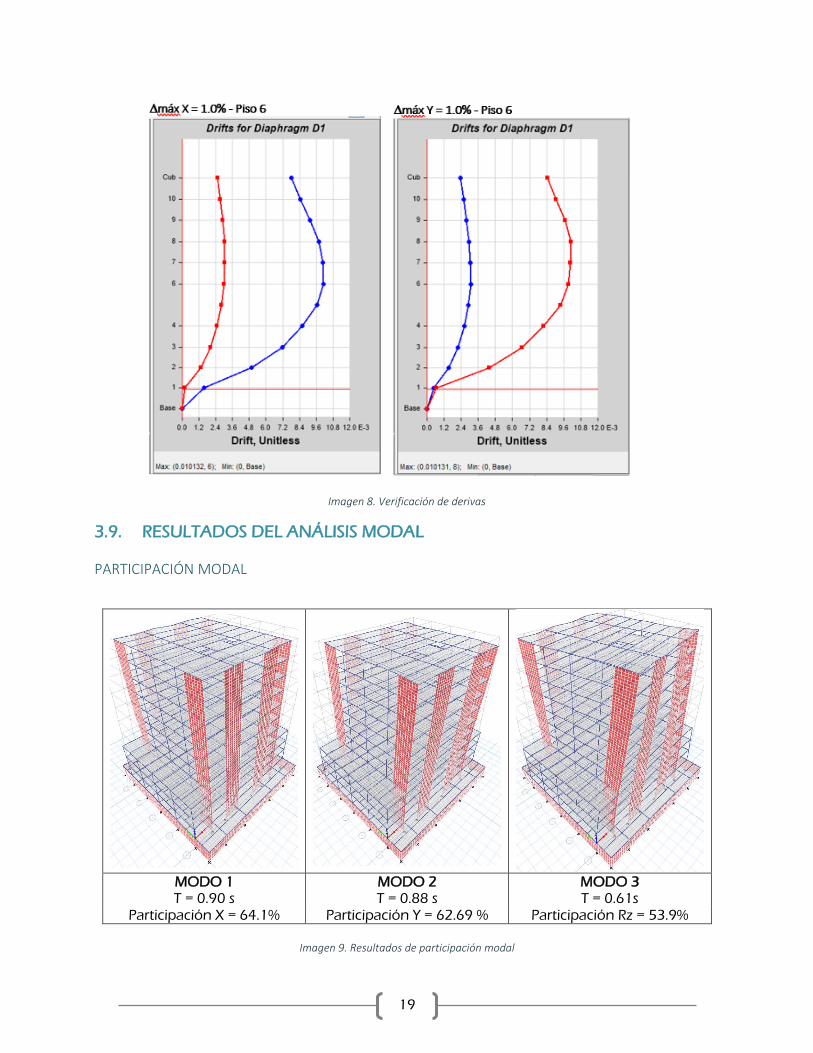
3.8. VERIFICACIÓN DE DERIVAS ................................................................................................. 18
3.9. RESULTADOS DEL ANÁLISIS MODAL ................................................................................ 19
PARTICIPACIÓN MODAL ................................................................................................................ 19
CENTROS DE MASA Y DE RIGIDEZ .............................................................................................. 20
FUERZAS DE PISO ............................................................................................................................. 20
4. ANÁLISIS NO LINEAL ELÁSTICO................................................................................................... 21
4.1. CLASIFICACIÓN DEL TIPO DE CONSTRUCCIÓN ............................................................ 21
4.2. COMPARACIÓN ENTRE LA MODELACIÓN LINEAL CON SECCIONES FISURADAS
Y NO FISURADAS. .................................................................................................................................. 21
4.3. METODO DEL ANÁLISIS NO LINEAL PUSHOVER .......................................................... 25
4.3.1. CASOS DE CARGA NO LINEALES ............................................................................... 25
4.3.2. PROPIEDADES NO LINEALES DE LOS MATERIALES ............................................. 25
4.4. EVALUACIÓN DE LAS PROPIEDADES Y CURVAS DE COMPORTAMIENTO
INELÁSTICO ............................................................................................................................................. 27
4.4.1. DEFINICIÓN DE RÓTULAS PLÁSTICAS PARA VIGAS ............................................ 28
4.4.2. DEFINICIÓN DE RÓTULAS PLÁSTICAS PARA COLUMNAS ................................. 29
4.4.3. DEFINICIÓN DE RÓTULAS PLÁSTICAS PARA MUROS .......................................... 30
4.5. CONSIDERACIÓN DE PROPIEDADES NO GEOMÉTRICAS DE LOS ELEMENTOS . 31
4.6. EVALUACIÓN DE LA FLEXIBILIDAD DE LA CIMENTACIÓN ....................................... 31
5. RESULTADOS ...................................................................................................................................... 33
5.1. CURVA DE COMPORTAMIENTO EN LA DIRECCIÓN X ................................................ 33
5.2. CURVA DE COMPORTAMIENTO EN LA DIRECCIÓN Y ................................................. 34
5.3. PUNTO DE COMPORTAMIENTO ......................................................................................... 35
6. LIMITACIONES Y VERIFICACIONES DEL PROCEDIMIENTO DE ANÁLSIIS NO LINEAL
ESTÁTICO ..................................................................................................................................................... 38
6.1. DUCTILIDAD REQUERIDA ..................................................................................................... 38
6.2. DUCTILIDAD REQUERIDA ..................................................................................................... 39
7. NIVEL DE DESEMPEÑO Y MECANISMOS DE COLAPSO ....................................................... 40
8. MODIFICACIONES AL DISEÑO ORIGINAL ................................................................................ 43
9. PRESUPUESTO Y CANTIDADES DE OBRA ................................................................................. 44
10. CONCLUSIONES............................................................................................................................ 45
REFERENCIAS .............................................................................................................................................. 46

4
Tabla de imágenes
Imagen 1: Apéndice 4 - Zona de amenaza sísmica municipio de Duitama. _________________________________ 14 Imagen 2: Tabla A.2.4-3 Factores del coeficiente Fa ___________________________________________________ 14 Imagen 3: Tabla A.2.4-4 Valores del coeficiente Fv ____________________________________________________ 14 Imagen 4: Tabla A.2.5-1 Valores del coeficiente de importancia _________________________________________ 15 Imagen 5: Resumen de parámetros para el espectro de diseño. _________________________________________ 15 Imagen 6: Espectro elástico de aceleraciones de diseño - Edificio Orquídeas________________________________ 15 Imagen 7. Tabla A.3.2 NSR-10 - Sistema estructural ___________________________________________________ 15 Imagen 8. Verificación de derivas _________________________________________________________________ 19 Imagen 9. Resultados de participación modal ________________________________________________________ 19 Imagen 10. Tabla 10-5 Valores de rigidez efectiva ASCE/SEI 41-17 _______________________________________ 21 Imagen 11. Asignación de factores de fisuración de vigas y muros _______________________________________ 22 Imagen 12. Asignación de factores de fisuración en Columnas __________________________________________ 23 Imagen 13. Resultados del análisis modal sin considerar la rigidez efectiva de los elementos __________________ 24 Imagen 14. Resultados del análisis modal considerando la rigidez efectiva de los elementos ___________________ 24 Imagen 15. Comparación de los resultados del análisis modal para los casos en los que se considera o no se considera
la rigidez efectiva de los elementos ________________________________________________________________ 25 Imagen 16. Relación fuerza – deformación unitaria del acero de refuerzo (Moehle 2011) _____________________ 26 Imagen 17. Relación fuerza – deformación unitaria del acero de refuerzo (Moehle 2011) _____________________ 26 Imagen 18. Relación fuerza – deformación unitaria del concreto reforzado ________________________________ 27 Imagen 19. Relación fuerza – desplazamiento ASCE/SEI 41-17 __________________________________________ 27 Imagen 20. Definición de rótulas plásticas en vigas ___________________________________________________ 29 Imagen 21. Definición de rótulas plásticas en columnas ________________________________________________ 29 Imagen 22. Comportamiento no lineal de un muro esbelto. Moehle 2011 __________________________________ 30 Imagen 23. Definición de rótulas plásticas en muros __________________________________________________ 30 Imagen 24. Curvas de comportamiento sentido X _____________________________________________________ 33 Imagen 25. Curvas de comportamiento sentido X – formato FEMA750 ____________________________________ 34 Imagen 26. Curvas de comportamiento sentido Y _____________________________________________________ 34 Imagen 27. Curvas de comportamiento sentido Y – formato FEMA750 ____________________________________ 35

5
RESUMEN
El presente documento contiene el desarrollo de los procedimientos efectuados en el análisis y
diseño estructural del proyecto denominado edificio Orquídeas, ubicado en la ciudad de Duitama,
Boyacá. Su configuración se desarrolla en 1 sótano, 10 pisos en altura y una cubierta para uso
comunal. La ciudad de Duitama se encuentra ubicada en zona de amenaza sísmica alta y debido
la tipología estructural del edificio se ha realizado el diseño teniendo en cuenta capacidad especial
de disipación de energía de acuerdo con las prescripciones del reglamento colombiano de
construcción sismo resistente NSR-10.
El trabajo se ha realizado en las siguientes fases de estudio. En primer lugar, se ha realizado la
recopilación y análisis de la información general y la arquitectura del proyecto con el fin de realizar
un pre-dimensionamiento estructural y un proceso de coordinación. Igualmente se realizó la
selección del sistema estructural y las características de los materiales que se utilizarán en el
proceso de diseño así como la definición del tipo de cimentación basados en las recomendaciones
del estudio geotécnico.
Como segunda fase se procedió a realizar el diseño estructural definitivo del edificio siguiendo los
requerimientos y especificaciones consignados en el Reglamento Colombiano de Construcción
Sismo Resistente del año 2010. El caso particular es de un sistema Combinado de Muros y Pórticos
Resistentes a Momento de Concreto Reforzado en las dos direcciones principales de la estructura
y la cimentación está compuesta de caisson.
Finalmente, se realizó el análisis no lineal estático de la estructura basados en los procedimientos
y requerimientos del documento ASCE/SEI 41-17, con el fin de establecer el nivel de desempeño
de la estructura y el comportamiento y los mecanismos de falla de la estructura.
Palabras clave: Diseño estructura, NSR-10, Sistema Combinado, Pushover.
6
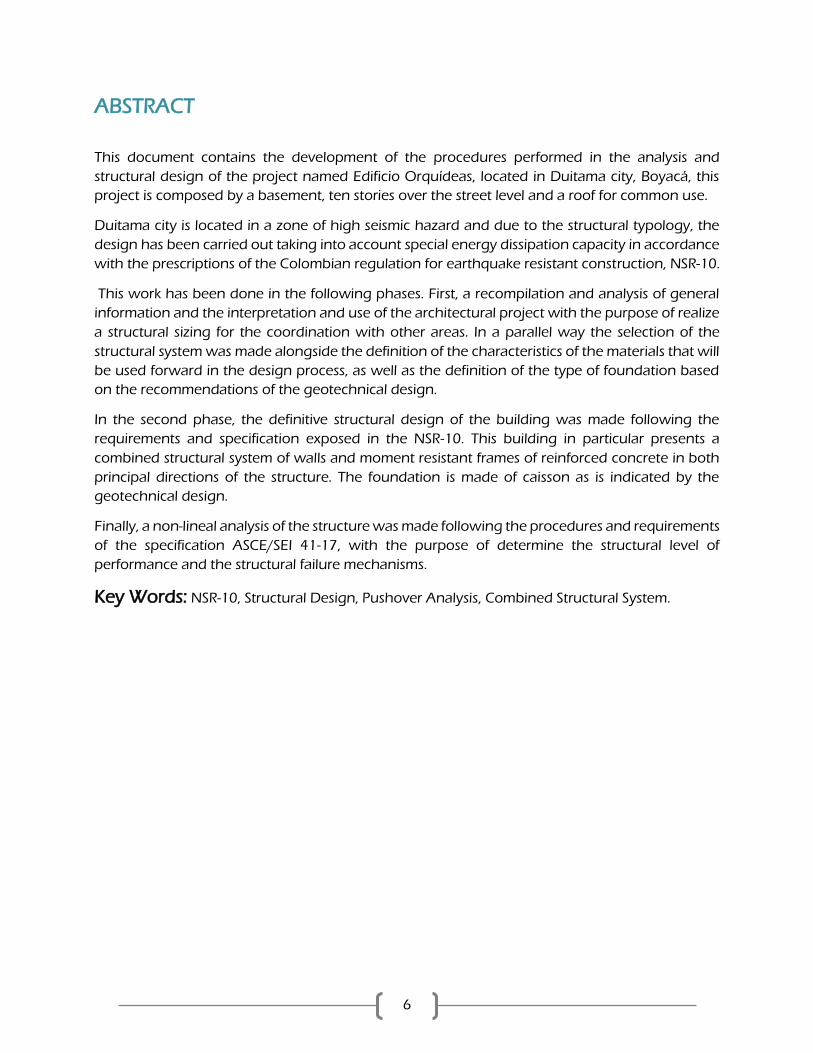
ABSTRACT
This document contains the development of the procedures performed in the analysis and
structural design of the project named Edificio Orquídeas, located in Duitama city, Boyacá, this
project is composed by a basement, ten stories over the street level and a roof for common use.
Duitama city is located in a zone of high seismic hazard and due to the structural typology, the
design has been carried out taking into account special energy dissipation capacity in accordance
with the prescriptions of the Colombian regulation for earthquake resistant construction, NSR-10.
This work has been done in the following phases. First, a recompilation and analysis of general
information and the interpretation and use of the architectural project with the purpose of realize
a structural sizing for the coordination with other areas. In a parallel way the selection of the
structural system was made alongside the definition of the characteristics of the materials that will
be used forward in the design process, as well as the definition of the type of foundation based
on the recommendations of the geotechnical design.
In the second phase, the definitive structural design of the building was made following the
requirements and specification exposed in the NSR-10. This building in particular presents a
combined structural system of walls and moment resistant frames of reinforced concrete in both
principal directions of the structure. The foundation is made of caisson as is indicated by the
geotechnical design.
Finally, a non-lineal analysis of the structure was made following the procedures and requirements
of the specification ASCE/SEI 41-17, with the purpose of determine the structural level of
performance and the structural failure mechanisms.
Key Words: NSR-10, Structural Design, Pushover Analysis, Combined Structural System.
7
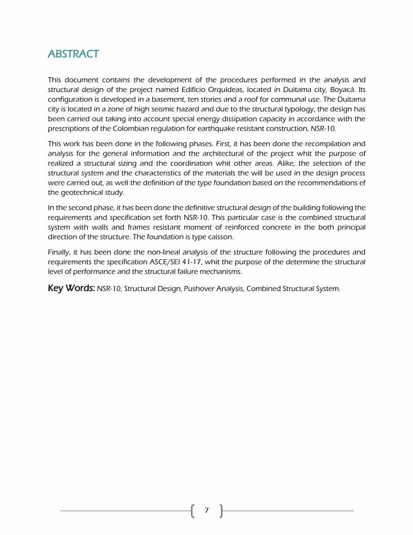
ABSTRACT
This document contains the development of the procedures performed in the analysis and
structural design of the project named Edificio Orquídeas, located in Duitama city, Boyacá. Its
configuration is developed in a basement, ten stories and a roof for communal use. The Duitama
city is located in a zone of high seismic hazard and due to the structural typology, the design has
been carried out taking into account special energy dissipation capacity in accordance with the
prescriptions of the Colombian regulation for earthquake resistant construction, NSR-10.
This work has been done in the following phases. First, it has been done the recompilation and
analysis for the general information and the architectural of the project whit the purpose of
realized a structural sizing and the coordination whit other areas. Alike, the selection of the
structural system and the characteristics of the materials the will be used in the design process
were carried out, as well the definition of the type foundation based on the recommendations ef
the geotechnical study.
In the second phase, it has been done the definitive structural design of the building following the
requirements and specification set forth NSR-10. This particular case is the combined structural
system with walls and frames resistant moment of reinforced concrete in the both principal
direction of the structure. The foundation is type caisson.
Finally, it has been done the non-lineal analysis of the structure following the procedures and
requirements the specification ASCE/SEI 41-17, whit the purpose of the determine the structural
level of performance and the structural failure mechanisms.
Key Words: NSR-10, Structural Design, Pushover Analysis, Combined Structural System.

8
INTRODUCCIÓN
El desarrollo de estructuras y edificaciones destinadas al uso residencial en las principales ciudades
y capitales de Colombia ha ido creciendo en los últimos años. Al inspeccionar el mapa de amenaza
sísmica del país, se logra observar como la gran mayoría de las ciudades capitales se encuentran
ubicadas en zonas de amenaza sísmicas intermedia y alta. Es por esto, que se vuelve indispensable
y de gran importancia contar con estándares y reglamentos de sismo resistencia que sean acordes
a las necesidades del entorno nacional y que permitan reducir la vulnerabilidad de las estructuras
ante eventos sísmicos.
El objetivo principal del trabajo consiste en realizar un análisis estático no lineal, Pushover, a un
edificio residencial ubicado en zona de amenaza sísmica alta, el cual sea diseñado con los
requisitos de sismo resistencia especificados en el reglamento colombiano de construcción sismo
resistente NSR-10. Con este análisis se pretende evaluar el comportamiento de la estructura
trabajando en el rango inelástico y con el detallamiento de refuerzo particular en cumplimiento
del NSR-10.
Por lo tanto, el primer paso del trabajo fue realizar el diseño tradicional según el reglamento.
Inicialmente se realiza la pre-dimensión de los elementos estructurales y se establecen los
requerimientos mínimos que se deben tener en cuenta para el diseño estructural. En dicho
documento se selecciona, los movimientos sísmicos de diseño de acuerdo con la ubicación de la
estructura y el tipo de suelo. Para el caso de estudio se encuentra que el edificio está ubicado en
zona de amenaza sísmica alta y tipo de suelo D.
Posteriormente, se selecciona el grado de disipación de energía teniendo en cuenta la zona de
amenaza sísmica y la configuración estructural del edificio. Para el caso de Colombia se tienen tres
capacidades de disipación de energía: Mínima, Moderada y Especial. Para el caso de zonas de
amenaza sísmica alta el reglamento limita a que el diseño estructural se realice utilizando
capacidad especial de disipación de energía.
Una vez determinados estos parámetros y las cargas gravitacionales de servicio se realizó la
modelación tridimensional del edificio y se obtienen las fuerzas internas

9
1. ARQUITECTURA Y DESCRIPCIÓN GENERAL DE LA
ESTRUCTURA
Para el diseño del edificio se cuenta con la disposición de la arquitectura propuesta, con el fin de
tener en cuenta la distribución de los espacios y poder realizar una adecuada coordinación junto
con el arquitecto diseñador.
El proyecto Orquídeas se encuentra ubicado en un predio de un área aproximada de 841 m2. El
planteamiento arquitectónico contempla la construcción de una torre con una configuración
estructural en sistema combinado de muros y pórticos en concreto con capacidad especial de
disipación de energía. El área total de construcción es de aproximadamente 5745 m2. La
configuración en altura corresponde con un sótano y diez pisos de altura además de una terraza
comunal. La altura de entrepiso típica de los niveles de vivienda es de 2.55m y el nivel final de la
estructura es N+30.45. Las luces del proyecto varían entre aproximadamente 5.0 m y 7.5 m.
RESUMEN DEL PROYECTO
Localización: Duitama, Boyacá
Uso: Residencial
Grupo de Uso: I
Materiales estructurales: Concreto reforzado.
Sistema estructural: Sistema combinado de muros y pórticos de concreto.
Perfil de suelo: D
Zona de amenaza sísmica: Alta.
Número de pisos: Sótano, 10 pisos y terraza.
Cubierta: En placa para uso social (terraza)
Altura de piso: 2.55m.
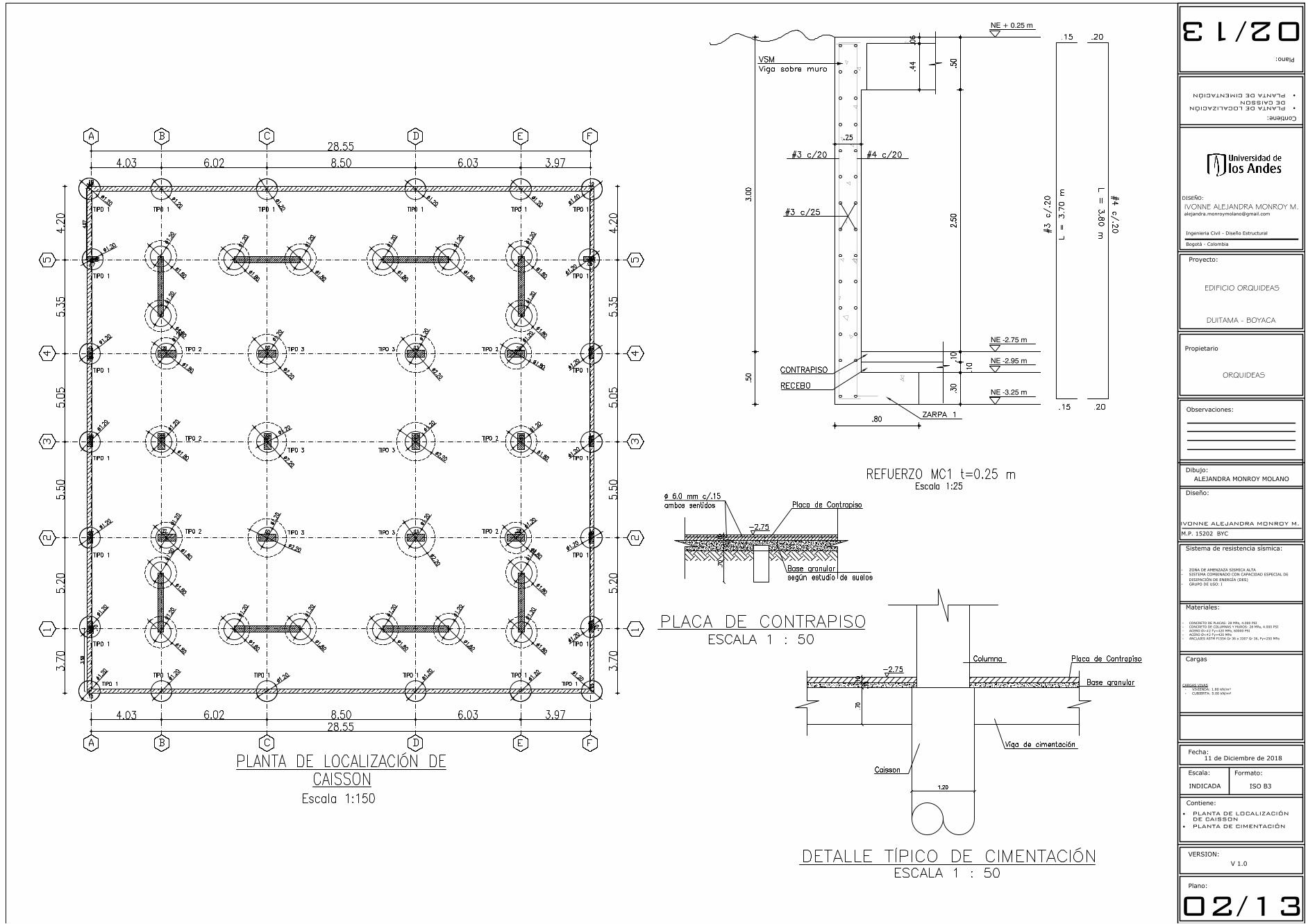
2. ESTUDIO GEOTÉCNICO
De acuerdo con el estudio de suelos el lote presenta una topografía principalmente plana en el
área del lote. En el estudio geotécnico no se evidencia que existan inconvenientes debidas a las
condiciones particulares del suelo, como podrían ser fenómenos de erosión inestabilidad, taludes,
entre otros. Sin embargo, si se encontró presencia de nivel freático a una profundidad alrededor
de los 3.0m. De acuerdo con las conclusiones del estudio, el suelo se puede categorizar como tipo
D. Se estima que las cargas transmitidas por la torre sean alrededor de 120 kN/m2. Los suelos
encontrados son en su mayoría arcillas y suelos finos.
Finalmente, las recomendaciones realizadas en el estudio corresponden a una cimentación
conformada por caisson a una profundidad mínima de 19.0 m con respecto al nivel cero del
proyecto.

10
3. PROCEDIMIENTO DE DISEÑO ESTRUCTURAL Y MEMORIA DE
CÁLCULOS
3.1. PREDIMENSIONAMIENTO Y COORDINACIÓN CON LOS OTROS
PROFESIONALES
3.1.1. SISTEMA DE ENTREPISO
3.1.2. REQUISITOS DE RESISTENCIA AL FUEGO
Teniendo en cuenta el grupo de ocupación
determinada en el punto anterior, la
edificación se puede ubicar en la categoría I
en la cual se encuentran las edificaciones con
mayor riesgo de pérdidas de vidas humanas
o con alta amenaza de combustión.
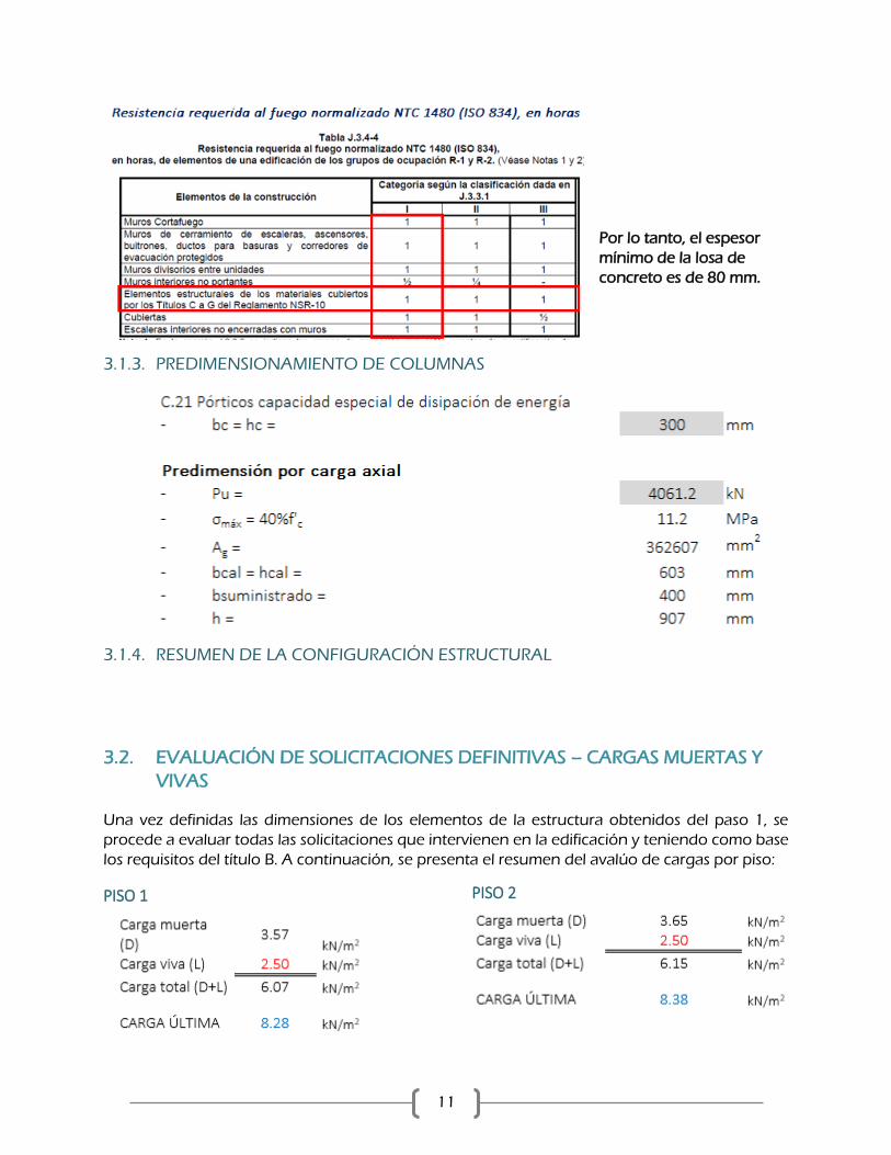
11
Por lo tanto, el espesor
mínimo de la losa de
concreto es de 80 mm.
3.1.3. PREDIMENSIONAMIENTO DE COLUMNAS
3.1.4. RESUMEN DE LA CONFIGURACIÓN ESTRUCTURAL
3.2. EVALUACIÓN DE SOLICITACIONES DEFINITIVAS – CARGAS MUERTAS Y
VIVAS
Una vez definidas las dimensiones de los elementos de la estructura obtenidos del paso 1, se
procede a evaluar todas las solicitaciones que intervienen en la edificación y teniendo como base
los requisitos del título B. A continuación, se presenta el resumen del avalúo de cargas por piso:
PISO 1
PISO 2

12
PISO 3 Y 4
PISO TIPO
CUBIERTA
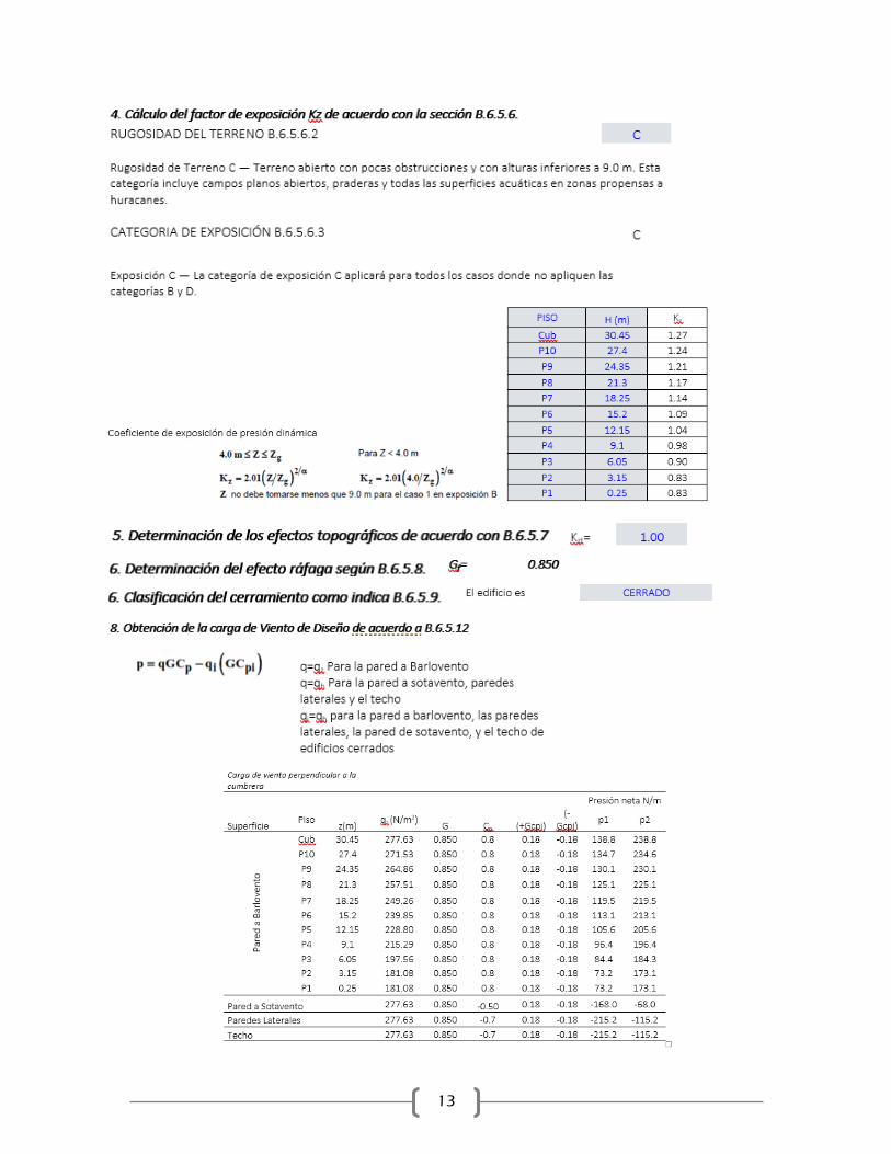
3.3. EVALUACIÓN DE SOLICITACIONES DEFINITIVAS – CARGAS DE VIENTO
13
14
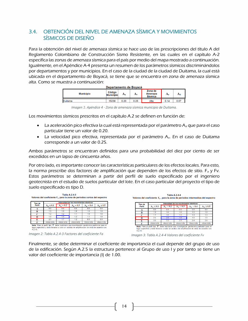
3.4. OBTENCIÓN DEL NIVEL DE AMENAZA SÍSMICA Y MOVIMIENTOS
SÍSMICOS DE DISEÑO
Para la obtención del nivel de amenaza sísmica se hace uso de las prescripciones del título A del
Reglamento Colombiano de Construcción Sismo Resistente, en las cuales en el capítulo A-2
especifica las zonas de amenaza sísmica para el país por medio del mapa mostrado a continuación.
Igualmente, en el Apéndice A-4 presenta un resumen de los parámetros sísmicos discriminándolos
por departamentos y por municipios. En el caso de la ciudad de la ciudad de Duitama, la cual está
ubicada en el departamento de Boyacá, se tiene que se encuentra en zona de amenaza sísmica
alta. Como se muestra a continuación:
Imagen 1: Apéndice 4 - Zona de amenaza sísmica municipio de Duitama.
Los movimientos sísmicos prescritos en el capítulo A.2 se definen en función de:
La aceleración pico efectiva la cual está representada por el parámetro Aa que para el caso
particular tiene un valor de 0.20.
La velocidad pico efectiva, representada por el parámetro Av. En el caso de Duitama
corresponde a un valor de 0.25.
Ambos parámetros se encuentran definidos para una probabilidad del diez por ciento de ser
excedidos en un lapso de cincuenta años.
Por otro lado, es importante conocer las características particulares de los efectos locales. Para esto,
la norma prescribe dos factores de amplificación que dependen de los efectos de sitio. Fa y Fv.
Estos parámetros se determinan a partir del perfil de suelo especificado por el ingeniero
geotecnista en el estudio de suelos particular del lote. En el caso particular del proyecto el tipo de
suelo especificado es tipo D.
Imagen 2: Tabla A.2.4-3 Factores del coeficiente Fa
Imagen 3: Tabla A.2.4-4 Valores del coeficiente Fv
Finalmente, se debe determinar el coeficiente de importancia el cual depende del grupo de uso
de la edificación. Según A.2.5 la estructura pertenece al Grupo de uso I y por tanto se tiene un
valor del coeficiente de importancia (I) de 1.00.
15
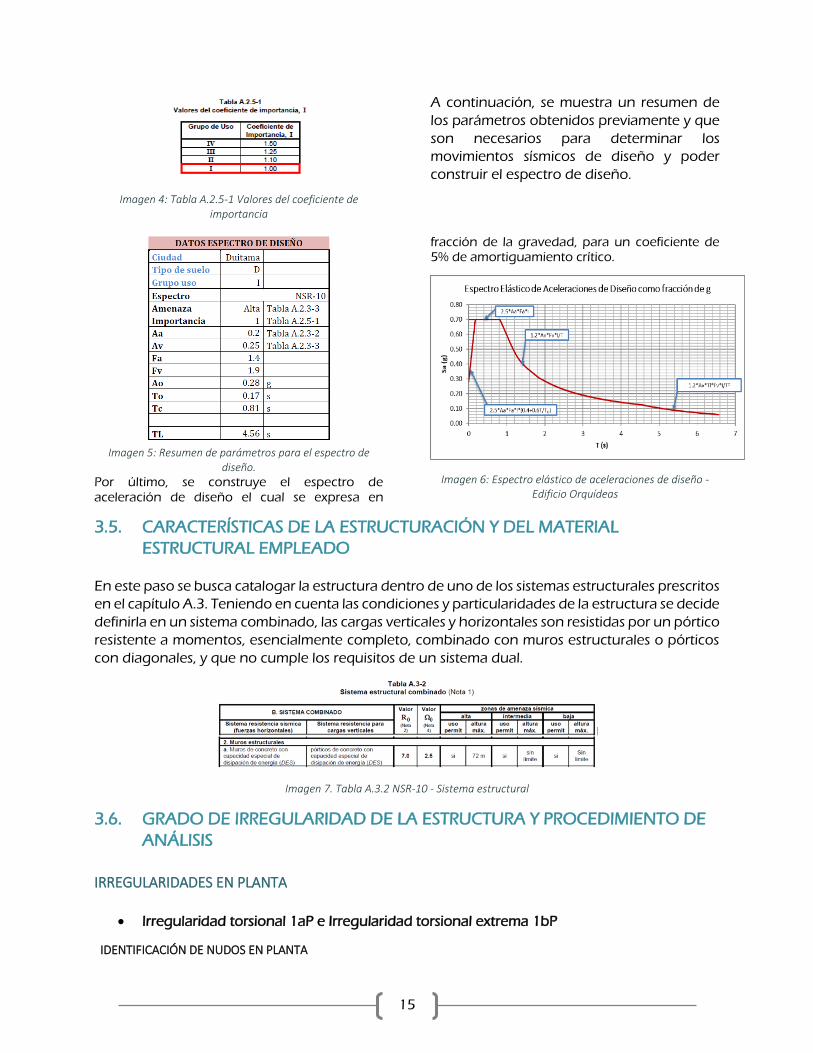
Imagen 4: Tabla A.2.5-1 Valores del coeficiente de importancia
A continuación, se muestra un resumen de
los parámetros obtenidos previamente y que
son necesarios para determinar los
movimientos sísmicos de diseño y poder
construir el espectro de diseño.
Imagen 5: Resumen de parámetros para el espectro de
diseño.
Por último, se construye el espectro de aceleración de diseño el cual se expresa en
fracción de la gravedad, para un coeficiente de 5% de amortiguamiento crítico.
Imagen 6: Espectro elástico de aceleraciones de diseño - Edificio Orquídeas
3.5. CARACTERÍSTICAS DE LA ESTRUCTURACIÓN Y DEL MATERIAL
ESTRUCTURAL EMPLEADO
En este paso se busca catalogar la estructura dentro de uno de los sistemas estructurales prescritos
en el capítulo A.3. Teniendo en cuenta las condiciones y particularidades de la estructura se decide
definirla en un sistema combinado, las cargas verticales y horizontales son resistidas por un pórtico
resistente a momentos, esencialmente completo, combinado con muros estructurales o pórticos
con diagonales, y que no cumple los requisitos de un sistema dual.
Imagen 7. Tabla A.3.2 NSR-10 - Sistema estructural
3.6. GRADO DE IRREGULARIDAD DE LA ESTRUCTURA Y PROCEDIMIENTO DE
ANÁLISIS
IRREGULARIDADES EN PLANTA
Irregularidad torsional 1aP e Irregularidad torsional extrema 1bP
IDENTIFICACIÓN DE NUDOS EN PLANTA

16
133
148
129 144
Nudo 133 129
Piso Δ Δ (Δ+Δ)/2 Δmáx/(Δ+Δ)/2 VERIFICACIÓN IT VERIFICACIÓN ITE
Cub mm mm
10 20.599 21.287 20.94 1.016 Cumple Cumple
9 22.498 23.365 22.93 1.019 Cumple Cumple
8 24.687 25.775 25.23 1.022 Cumple Cumple
7 26.667 27.978 27.32 1.024 Cumple Cumple
6 27.966 29.462 28.71 1.026 Cumple Cumple
5 28.166 29.778 28.97 1.028 Cumple Cumple
4 26.785 28.401 27.59 1.029 Cumple Cumple
3 23.612 25.101 24.36 1.031 Cumple Cumple
2 18.023 19.171 18.60 1.031 Cumple Cumple
Nudo 148 144
Piso Δ Δ (Δ+Δ)/2 Δmáx/(Δ+Δ)/2 VERIFICACIÓN IT VERIFICACIÓN ITE
Cub mm mm
10 20.599 21.287 20.94 1.016 Cumple Cumple
9 22.498 23.365 22.93 1.019 Cumple Cumple
8 24.687 25.775 25.23 1.022 Cumple Cumple
7 26.667 27.978 27.32 1.024 Cumple Cumple
6 27.966 29.462 28.71 1.026 Cumple Cumple
5 28.166 29.778 28.97 1.028 Cumple Cumple
4 26.785 28.401 27.59 1.029 Cumple Cumple
3 23.612 25.101 24.36 1.031 Cumple Cumple
2 18.023 19.171 18.60 1.031 Cumple Cumple
Nudo 133 148
Piso Δ Δ (Δ+Δ)/2 Δmáx/(Δ+Δ)/2 VERIFICACIÓN IT VERIFICACIÓN ITE
Cub mm mm
10 20.852 20.947 20.90 1.002 Cumple Cumple
9 22.879 22.986 22.93 1.002 Cumple Cumple
8 25.271 25.396 25.33 1.002 Cumple Cumple
7 27.499 27.645 27.57 1.003 Cumple Cumple
6 29.061 29.233 29.15 1.003 Cumple Cumple
5 29.522 29.724 29.62 1.003 Cumple Cumple
4 28.412 28.649 28.53 1.004 Cumple Cumple
3 25.25 25.528 25.39 1.005 Cumple Cumple
2 19.337 19.56 19.45 1.006 Cumple Cumple

17
3.7. ANÁLISIS SÍSMICO DE LA ESTRUCTURA

18
3.8. VERIFICACIÓN DE DERIVAS
19
Imagen 8. Verificación de derivas
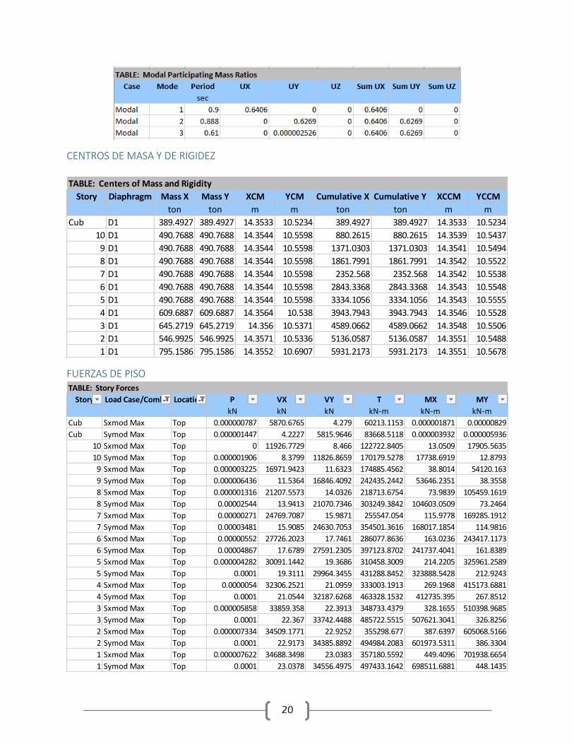
3.9. RESULTADOS DEL ANÁLISIS MODAL
PARTICIPACIÓN MODAL
MODO 1 MODO 2 MODO 3 T = 0.90 s T = 0.88 s T = 0.61s
Participación X = 64.1% Participación Y = 62.69 % Participación Rz = 53.9%
Imagen 9. Resultados de participación modal
20
CENTROS DE MASA Y DE RIGIDEZ
FUERZAS DE PISO
TABLE: Centers of Mass and Rigidity
Story Diaphragm Mass X Mass Y XCM YCM Cumulative X Cumulative Y XCCM YCCM
ton ton m m ton ton m m
Cub D1 389.4927 389.4927 14.3533 10.5234 389.4927 389.4927 14.3533 10.5234
10 D1 490.7688 490.7688 14.3544 10.5598 880.2615 880.2615 14.3539 10.5437
9 D1 490.7688 490.7688 14.3544 10.5598 1371.0303 1371.0303 14.3541 10.5494
8 D1 490.7688 490.7688 14.3544 10.5598 1861.7991 1861.7991 14.3542 10.5522
7 D1 490.7688 490.7688 14.3544 10.5598 2352.568 2352.568 14.3542 10.5538
6 D1 490.7688 490.7688 14.3544 10.5598 2843.3368 2843.3368 14.3543 10.5548
5 D1 490.7688 490.7688 14.3544 10.5598 3334.1056 3334.1056 14.3543 10.5555
4 D1 609.6887 609.6887 14.3564 10.538 3943.7943 3943.7943 14.3546 10.5528
3 D1 645.2719 645.2719 14.356 10.5371 4589.0662 4589.0662 14.3548 10.5506
2 D1 546.9925 546.9925 14.3571 10.5336 5136.0587 5136.0587 14.3551 10.5488
1 D1 795.1586 795.1586 14.3552 10.6907 5931.2173 5931.2173 14.3551 10.5678
TABLE: Story Forces
Story Load Case/Combo Location P VX VY T MX MY
kN kN kN kN-m kN-m kN-m
Cub Sxmod Max Top 0.000000787 5870.6765 4.279 60213.1153 0.000001871 0.00000829
Cub Symod Max Top 0.000001447 4.2227 5815.9646 83668.5118 0.000003932 0.000005936
10 Sxmod Max Top 0 11926.7729 8.466 122722.8405 13.0509 17905.5635
10 Symod Max Top 0.000001906 8.3799 11826.8659 170179.5278 17738.6919 12.8793
9 Sxmod Max Top 0.000003225 16971.9423 11.6323 174885.4562 38.8014 54120.163
9 Symod Max Top 0.000006436 11.5364 16846.4092 242435.2442 53646.2351 38.3558
8 Sxmod Max Top 0.000001316 21207.5573 14.0326 218713.6754 73.9839 105459.1619
8 Symod Max Top 0.00002544 13.9413 21070.7346 303249.3842 104603.0509 73.2464
7 Sxmod Max Top 0.00000271 24769.7087 15.9871 255547.054 115.9778 169285.1912
7 Symod Max Top 0.00003481 15.9085 24630.7053 354501.3616 168017.1854 114.9816
6 Sxmod Max Top 0.00000552 27726.2023 17.7461 286077.8636 163.0236 243417.1173
6 Symod Max Top 0.00004867 17.6789 27591.2305 397123.8702 241737.4041 161.8389
5 Sxmod Max Top 0.000004282 30091.1442 19.3686 310458.3009 214.2205 325961.2589
5 Symod Max Top 0.0001 19.3111 29964.3455 431288.8452 323888.5428 212.9243
4 Sxmod Max Top 0.0000054 32306.2521 21.0959 333003.1913 269.1968 415173.6881
4 Symod Max Top 0.0001 21.0544 32187.6268 463328.1532 412735.395 267.8512
3 Sxmod Max Top 0.000005858 33859.358 22.3913 348733.4379 328.1655 510398.9685
3 Symod Max Top 0.0001 22.367 33742.4488 485722.5515 507621.3041 326.8256
2 Sxmod Max Top 0.000007334 34509.1771 22.9252 355298.677 387.6397 605068.5166
2 Symod Max Top 0.0001 22.9173 34385.8892 494984.2083 601973.5311 386.3304
1 Sxmod Max Top 0.000007622 34688.3498 23.0383 357180.5592 449.4096 701938.6654
1 Symod Max Top 0.0001 23.0378 34556.4975 497433.1642 698511.6881 448.1435

21
4. ANÁLISIS NO LINEAL ELÁSTICO
Tomando como base al análisis elástico y el diseño realizado previamente se realiza la
modelación computacional para el análisis no lineal elástico de la estructura. Para dicha
modelación se decide utilizar como base el modelo computacional desarrollado en el
software ETABS2016®, en donde se incluirán las herramientas necesarias para realizar el
correspondiente análisis. Este tipo de análisis se realizó siguiendo los lineamientos del
ASCE/SEI41-17.
El software de análisis permite incluir el comportamiento de elementos estructurales
mediante modelos de rótulas concentras en el caso de los elementos tipo frame, vigas y
columnas. Para los elementos tipo Shell, es decir los muros, se crean modelos de fibras
discretizando la sección del muro teniendo en cuenta los materiales que lo conforman y de
esta manera construye las curvas esfuerzo deformación.
4.1. CLASIFICACIÓN DEL TIPO DE CONSTRUCCIÓN
Se realiza la clasificación de la estructura tomando como base la Tabla 3-1 del documento
ASCE/SEI41-17 y clasificándolo como tipo C1 – Concrete Moment Frames.
4.2. COMPARACIÓN ENTRE LA MODELACIÓN LINEAL CON SECCIONES
FISURADAS Y NO FISURADAS.
En primera medida se procede a realizar la modelación de la rigidez efectiva de los
componentes estructurales tales como vigas columnas y muros. Para esto se toma como
base los requerimientos presentados en la tabla 10-5 del ASCE/SEI41-17:
Imagen 10. Tabla 10-5 Valores de rigidez efectiva ASCE/SEI 41-17

22
FISURACIÓN DE VIGAS FISURACIÓN DE MUROS
Por tanto, en el caso de las vigas de tiene un factor de fisuración de flexión de 0.3 el cual fue asignado a cada sección siguiendo el siguiente procedimiento:
Para el caso de los muros se incluye un factor de fisuración de 0.35 como se presenta en la siguiente imagen:
Imagen 11. Asignación de factores de fisuración de vigas y muros
FISURACIÓN DE COLUMNAS
Para las columnas se encontró el factor de fisuración en relación con las cargas axiales de
cada elemento en cada nivel. Con el fin de exponer el procedimiento realizado se muestra
el caso particular del piso 3:

23
Imagen 12. Asignación de factores de fisuración en Columnas

24
Inicialmente se realiza una comparación entre los periodos y formas modales de la estructura
con los siguientes resultados:
MODO 1 MODO 2 MODO 3 T = 0.90 s T = 0.88 s T = 0.61s
Participación X = 64.1% Participación Y = 62.69 % Participación Rz = 53.9%
Imagen 13. Resultados del análisis modal sin considerar la rigidez efectiva de los elementos
MODO 1 MODO 2 MODO 3 T = 1.52 s T = 1.49 s T = 0.99s
Participación X = 62.3% Participación Y = 61.2 % Participación Rz = 52.9%
Imagen 14. Resultados del análisis modal considerando la rigidez efectiva de los elementos
25
Imagen 15. Comparación de los resultados del análisis modal para los casos en los que se considera o no se considera la rigidez efectiva de los elementos
4.3. METODO DEL ANÁLISIS NO LINEAL PUSHOVER
En cada uno de los análisis presentados en los numerales subsecuentes, se efectuará el
método de análisis no lineal estático “Pushover” con el fin de determinar la capacidad y el
comportamiento de la estructura.
4.3.1. CASOS DE CARGA NO LINEALES
Teniendo en cuenta las especificaciones consignadas en la sección 7.2 del ASCE/SEI 41-17
las fuerzas causadas por casos de carga vertical se denominan Qg, los cuales corresponden
a la combinación del 100% de la carga muerta más el 25% de la carga viva. Teniendo en
cuenta esto se crea el primer caso de carga no lineal el cual será el caso del que se partirá
para realizar la aplicación progresiva de la carga lateral.
De acuerdo con el estándar, capítulo 7.4.3.2.3, los casos no lineales de carga lateral se
aplican al modelo considerando una distribución proporcional al modo fundamental en la
dirección de análisis. Este análisis de carga lateral se realiza por medio del control de
desplazamiento de un nudo ubicado en la cubierta del edificio.
4.3.2. PROPIEDADES NO LINEALES DE LOS MATERIALES
Como es bien sabido, los materiales como el concreto y el acero de refuerzo presentan un
comportamiento no lineal luego de sobrepasar ciertas relaciones de esfuerzo – deformación.
Esta respuesta no lineal del de material tiene influencia sobre el comportamiento específico
de cada material. Por este motivo se han desarrollado modelos de comportamiento de los
materiales, para el caso del concreto se utilizará el modelo de Mander y para el caso del
acero de refuerzo a relación esfuerzo deformación del acero.
ACERO DE REFUERZO
La relación esfuerzo deformación del acero de refuerzo se ha determinado
experimentalmente a partil de ensayos del material. El resultado de estos modelos se
presenta en figura 16 (Moehle, 2011). El comportamiento se determina por medio del
ensayo de tensión de un espécimen sobre el cuales mide la elongación que este sufre a
medida que se aplica una carga monotónica hasta llegar al punto de falla.

26
Imagen 16. Relación fuerza – deformación unitaria del acero de refuerzo (Moehle 2011)
En la imagen 20 se muestra la curva de comportamiento definida para el acero de refuerzo.
La primera zona se caracteriza por presentar un comportamiento lineal hasta una
deformación unitaria de 0.0021en donde se presenta la fluencia del acero. Luego se
presenta una pequeña caída en resistencia en un rango de deformación muy corto y
finalmente se presenta endurecimiento por deformación que refleja la ductilidad del
material por medio de la deformación del material. El esfuerzo de fluencia del material es de
420 MPa y el factor de resistencia esperada es de 1.25.
Imagen 17. Relación fuerza – deformación unitaria del acero de refuerzo (Moehle 2011)
CONCRETO
El modelo utilizado corresponde al desarrollado por Mander et al (1988). Este modelo
relaciona el comportamiento esfuerzo – deformación teniendo en cuenta la interacción del
concreto simple y el comportamiento suministrado por el refuerzo transversal de la sección.

27
De acuerdo con la distribución del refuerzo transversal, la separación de las barras
longitudinales y el acero de refuerzo empleado se pueden determinar las curvas de
comportamiento para concreto confinado.
Imagen 18. Relación fuerza – deformación unitaria del concreto reforzado
4.4. EVALUACIÓN DE LAS PROPIEDADES Y CURVAS DE
COMPORTAMIENTO INELÁSTICO
El comportamiento inelástico de los elementos se ha modelado haciendo uso de rótulas
plásticas a flexión por medio de rótulas concentradas en los extremos de los elementos. Para
esto se hizo uso de los modelos momento rotación de concreto suministrados en el
documento ASCE/SEI41-17. Este documento define el comportamiento en función de
criterios de aceptabilidad y niveles de comportamiento como se muestra a continuación.
Imagen 19. Relación fuerza – desplazamiento ASCE/SEI 41-17

28
4.4.1. DEFINICIÓN DE RÓTULAS PLÁSTICAS PARA VIGAS
Para la definición de este modelo se tomaron rótulas plásticas concentradas en los puntos
donde se espera que se encuentren las secciones críticas durante la acción de fuerzas
sísmicas. Estas rótulas se definieron siguiendo las recomendaciones de la sección 10 del
ASCE/SEI 41-17, especialmente la tabla 10-7. A continuación se presenta un ejemplo de los
parámetros obtenidos para una viga:
Definición de rótulas plásticas controladas por flexión
ASCE/SEI 41-17 TABLA 10-7
Extremo izquierdo
Viga ID: V-302 Vano: 3
Extremo Izquierdo Longitud : 5.73 m
Geométria
b = 400 mm Drotula = 0.17
h = 500 mm
r = 60 mm d = 440 mm
r' = 60 mm d' = 440 mm
Refuerzo
As' = 1136 mm2 Área de refuerzo a compresión
As = 1733 mm2 Área de refuerzo a tensión
Materiales
f'c = 28 MPa Ec = 24870 MPa
fy = 420 MPa Es = 200000 MPa
β1 = 0.85
fs = 525 MPa
Chequeos
ρ' = 0.00645
=
ρ = 0.00985 0.120
ρbal = 0.028
Mpr1 = 356.717 kN*m V(wu) = 42.6
Mpr2 = 243.679 kN*m Ve= 147.38 kN
𝜌 − 𝜌′
𝜌𝑏𝑎𝑙
29
Imagen 20. Definición de rótulas plásticas en vigas
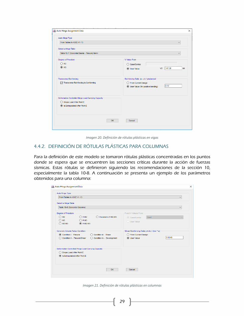
4.4.2. DEFINICIÓN DE RÓTULAS PLÁSTICAS PARA COLUMNAS
Para la definición de este modelo se tomaron rótulas plásticas concentradas en los puntos
donde se espera que se encuentren las secciones críticas durante la acción de fuerzas
sísmicas. Estas rótulas se definieron siguiendo las recomendaciones de la sección 10,
especialmente la tabla 10-8. A continuación se presenta un ejemplo de los parámetros
obtenidos para una columna:
Imagen 21. Definición de rótulas plásticas en columnas

30
4.4.3. DEFINICIÓN DE RÓTULAS PLÁSTICAS PARA MUROS
Las rotulas de muros fueron asignadas mediante un modelo de fibras P-M3. Este modelo
permite representar el comportamiento del elemento teniendo en cuenta los efectos de
carga axial y flexión en el plano fuerte del muro. De acuerdo con el Analisis Reference
Manual (2017) de CSI, las rótulas tipo P-M3 actúan en la mitad del elemento tipo shell.
La condición que se pretende modelar en muros sometidos a cargas laterales consiste en
que la capacidad no lineal de estos elementos se produzca por medio de rotulas ubicadas
en los primeros niveles de la estructura como se puede encontrar en la imagen mostrada
(Moehle 2011).
Imagen 22. Comportamiento no lineal de un muro esbelto. Moehle 2011
Imagen 23. Definición de rótulas plásticas en muros

31
4.5. CONSIDERACIÓN DE PROPIEDADES NO GEOMÉTRICAS DE LOS
ELEMENTOS
Adicionalmente, se tuvo bajo consideración los efectos P-Delta sobre la estructura. Estos
efectos se encuentran asociados a la condición de carga vertical en una estructura
previamente deformada. Para tener en cuenta dichos efectos en el análisis se utilizó la
condición de no linealidad geométrica en el caso de carga gravitacional no lineal y en el
subsecuente caso de carga lateral.
4.6. EVALUACIÓN DE LA FLEXIBILIDAD DE LA CIMENTACIÓN
Con el fin de simular el comportamiento del suelo de fundación, considerando que este se
comporta como un material con unas características de rigidez y resistencia particulares, es
necesario incluir dentro de la evaluación de comportamiento estructural el análisis que
incluya la flexibilidad de la cimentación.
Los componentes de la cimentación fueron modelados teniendo en cuenta la interacción
del suelo y la cimentación y simplificándola a resortes verticales y horizontales con rigideces
equivalente. El análisis se realizó tomando como base de referencia las provisiones
encontradas en el capítulo 8 del documento ASCE/SEI41-17 y las consignadas en el
documento NIST GCR 12-917-21.
El suelo se representa mediante resortes que representan la rigidez dinámica axial y lateral
de las pilas sobre las cuales de apoyan los elementos que llegan a cimentación.
CONSTANTE EQUIVALENTE PARA REPESENTAR LA RIGIDEZ VERTICAL Y HORIZONTAL
La rigidez dinámica de una pila puede ser representada como el producto de la rigidez
estática y un factor de modificación dinámico, dicho procedimiento se resume como:
𝑘𝑗𝑝 = 𝐾𝑗
𝑝𝑥 ∝𝑗𝑝
En donde:
𝐾𝑗𝑝 = 𝑥𝑗𝐸𝑠𝑑
𝑥𝑗 = (𝑤𝑝𝑗 + 𝑤𝑠𝑗 + 𝑤𝑏𝑗)𝑓 (𝐸𝑝
𝐸𝑠, 𝐿𝑝/𝑑)
∝𝑗𝑝= 𝑓 (
𝐸𝑝
𝐸𝑠,𝜌𝑝
𝜌𝑠, 𝑤𝑠𝑗 , 𝜐, 𝑎0
𝑝)
𝑥𝑗: 𝐶𝑜𝑛𝑠𝑡𝑎𝑛𝑡𝑒 𝑎𝑑𝑖𝑚𝑒𝑛𝑠𝑖𝑜𝑛𝑎𝑙 𝑑𝑒𝑙 𝑚𝑜𝑑𝑜 𝑑𝑒 𝑣𝑜𝑏𝑟𝑎𝑐𝑖ó𝑛 𝑗
𝑑: 𝐷𝑖á𝑚𝑒𝑡𝑟𝑜 𝑑𝑒 𝑙𝑎 𝑝𝑖𝑙𝑎
𝐸𝑠: 𝑀ó𝑑𝑢𝑙𝑜 𝑑𝑒 𝑒𝑙𝑎𝑠𝑡𝑖𝑐𝑖𝑑𝑎𝑑 𝑑𝑒𝑙 𝑠𝑢𝑒𝑙𝑜
𝐸𝑝: 𝑀ó𝑑𝑢𝑙𝑜 𝑑𝑒 𝑒𝑙𝑎𝑠𝑡𝑖𝑐𝑖𝑑𝑎𝑑 𝑑𝑒𝑙 𝑚𝑎𝑡𝑒𝑟𝑖𝑎𝑙 𝑑𝑒 𝑙𝑎 𝑝𝑖𝑙𝑎
𝜌𝑠: 𝐷𝑒𝑛𝑠𝑖𝑑𝑎𝑑 𝑑𝑒𝑙 𝑠𝑢𝑒𝑙𝑜
𝜌𝑝: 𝐷𝑒𝑛𝑠𝑖𝑑𝑎𝑑 𝑑𝑒𝑙 𝑚𝑎𝑡𝑒𝑟𝑖𝑎𝑙 𝑑𝑒 𝑙𝑎 𝑝𝑖𝑙𝑎
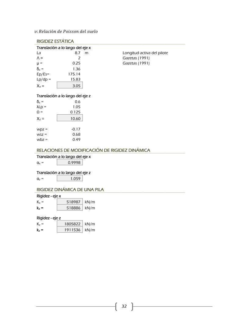
32
𝜐: 𝑅𝑒𝑙𝑎𝑐𝑖ó𝑛 𝑑𝑒 𝑃𝑜𝑖𝑠𝑠𝑜𝑛 𝑑𝑒𝑙 𝑠𝑢𝑒𝑙𝑜
RIGIDEZ ESTÁTICA
Translación a lo largo del eje x
La 8.7 m Longitud activa del pilote
Λ = 2 Gazetas (1991)
μ = 0.25 Gazetas (1991)
δx = 1.36
Ep/Es= 175.14
Lp/dp = 15.83
Χx = 3.05
Translación a lo largo del eje z
δz = 0.6
λLp = 1.05
Ω = 0.125
Χz = 10.60
wpz = -0.17
wsz = 0.68
wbz = 0.49
RELACIONES DE MODIFICACIÓN DE RIGIDEZ DINÁMICA
Translación a lo largo del eje x
αx = 0.9998
Translación a lo largo del eje z
αz = 1.059
RIGIDEZ DINÁMICA DE UNA PILA
Rigidez - eje x
Kx = 518987 kN/m
kx = 518886 kN/m
Rigidez - eje z
Kz = 1805822 kN/m
kz = 1911536 kN/m

33
5. RESULTADOS
De acuerdo con las secciones previas se ha desarrollado 3 modelos de análisis en cada
dirección para los cuales se describen las principales características a continuación.
SENTIDO X SENTIDO Y
Modelo 1. - Apoyos empotrados en la base de
elementos tipo columna y apoyos de segundo orden en la base de elementos tipo muros.
- No linealidad del material.
Modelo 2. - Apoyos empotrados en la base de
elementos tipo columna y apoyos de segundo orden en la base de elementos tipo muros.
No linealidad del material.
Modelo 3. - Apoyos empotrados en la base de
elementos tipo columna y apoyos de segundo orden en la base de elementos tipo muros.
- No linealidad del material. - Efectos P-Delta.
Modelo 4. - Apoyos empotrados en la base de
elementos tipo columna y apoyos de segundo orden en la base de elementos tipo muros.
- No linealidad del material. - Efectos P-Delta.
Modelo 5.
- No linealidad del material. - Efectos P-Delta. - Flexibilidad de la cimentación.
Modelo 6.
- No linealidad del material. - Efectos P-Delta. - Flexibilidad de la cimentación.
5.1. CURVA DE COMPORTAMIENTO EN LA DIRECCIÓN X
Imagen 24. Curvas de comportamiento sentido X

34
Imagen 25. Curvas de comportamiento sentido X – formato FEMA750
5.2. CURVA DE COMPORTAMIENTO EN LA DIRECCIÓN Y
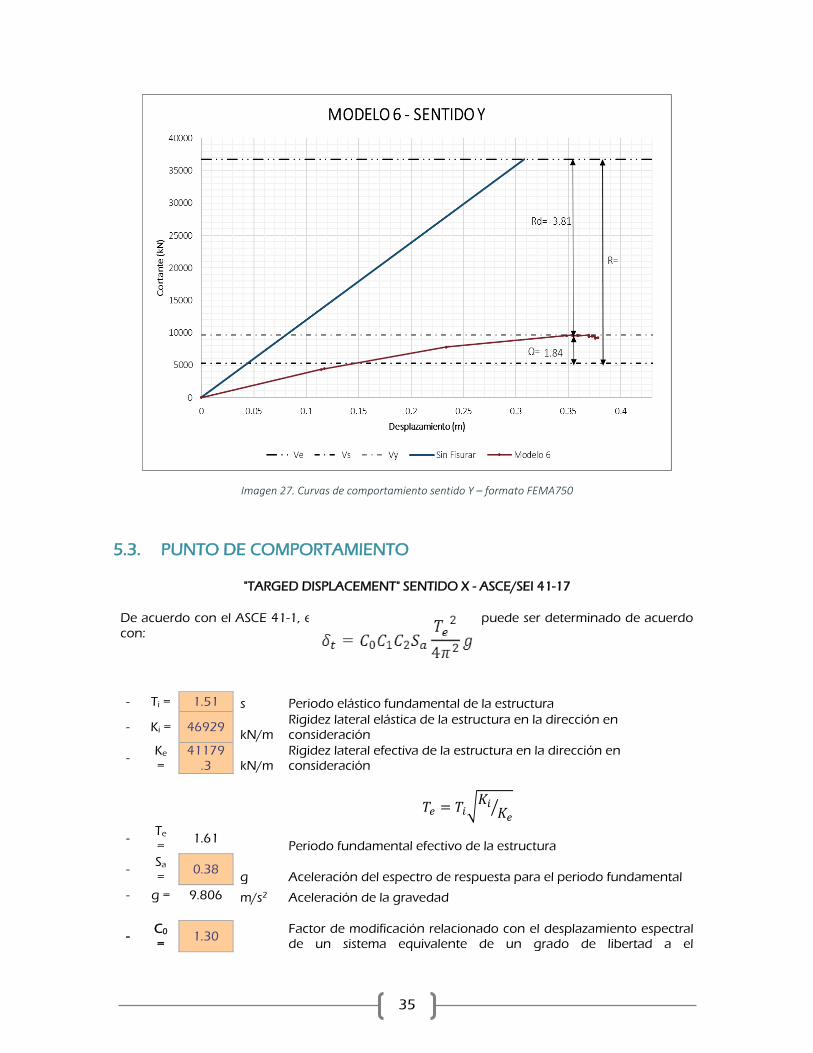
Imagen 26. Curvas de comportamiento sentido Y
35
Imagen 27. Curvas de comportamiento sentido Y – formato FEMA750
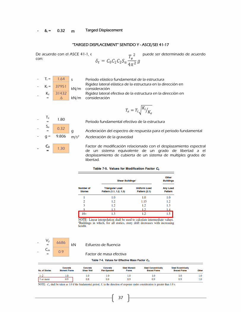
5.3. PUNTO DE COMPORTAMIENTO
"TARGED DISPLACEMENT" SENTIDO X - ASCE/SEI 41-17
De acuerdo con el ASCE 41-1, el punto de comportamiento puede ser determinado de acuerdo
con:
- Ti = 1.51 s Periodo elástico fundamental de la estructura
- Ki = 46929 kN/m
Rigidez lateral elástica de la estructura en la dirección en consideración
- Ke =
41179.3 kN/m
Rigidez lateral efectiva de la estructura en la dirección en consideración
- Te =
1.61 Periodo fundamental efectivo de la estructura
- Sa =
0.38 g Aceleración del espectro de respuesta para el periodo fundamental
- g = 9.806 m/s2 Aceleración de la gravedad
- C0 =
1.30
Factor de modificación relacionado con el desplazamiento espectral de un sistema equivalente de un grado de libertad a el
𝑇𝑒 = 𝑇𝑖√𝐾𝑖𝐾𝑒
⁄

36
desplazamiento de cubierta de un sistema de multiples grados de libertad.
- Vy
= 6164
kN Esfuerzo de fluencia
- Cm =
0.9 Factor de masa efectiva
- W =
51467.6 kN Peso efectivo de la estructura
- μstre
n = 2.833
- Tipo de suelo =
D
- α = 60 Factor de clase de Suelo
- C1 =
1.012
Factor de modificación relacionado con el desplazamiento máximo inelástico esperado para los desplazamientos calculados para una respuesta lineal elástica
Para periodos mayores a 0.7s C2=1.0
- C2 =
1.00
Factor de modificación que representa el efecto de la forma estrangulada de histeresis, la degradación cíclica de la rigidez y el deterioro de la resistencia al desplazamiento máximo.
37
- δt = 0.32 m Targed Displacement
"TARGED DISPLACEMENT" SENTIDO Y - ASCE/SEI 41-17
De acuerdo con el ASCE 41-1, el punto de comportamiento puede ser determinado de acuerdo con:
- Ti = 1.64 s Periodo elástico fundamental de la estructura
- Ki = 37951 kN/m
Rigidez lateral elástica de la estructura en la dirección en consideración
- Ke =
31432.6 kN/m
Rigidez lateral efectiva de la estructura en la dirección en consideración
- Te =
1.80 Periodo fundamental efectivo de la estructura
- Sa =
0.32 g Aceleración del espectro de respuesta para el periodo fundamental
- g = 9.806 m/s2 Aceleración de la gravedad
- C0 =
1.30
Factor de modificación relacionado con el desplazamiento espectral de un sistema equivalente de un grado de libertad a el desplazamiento de cubierta de un sistema de multiples grados de
libertad.
- Vy =
6686 kN Esfuerzo de fluencia
- Cm =
0.9 Factor de masa efectiva
𝑇𝑒 = 𝑇𝑖√𝐾𝑖𝐾𝑒
⁄

38
- W =
51467.6 kN Peso efectivo de la estructura
- μstre
n = 2.196
- Tipo de suelo =
D
- α = 60 Factor de clase de Suelo
- C1
= 1.006
Factor de modificación relacionado con el desplazamiento máximo
inelástico esperado para los desplazamientos calculados para una respuesta lineal elástica
Para periodos mayores a 0.7s C2=1.0
- C2 =
1.00
Factor de modificación que representa el efecto de la forma estrangulada de histeresis, la degradación cíclica de la rigidez y el deterioro de la resistencia al desplazamiento máximo.
- δt = 0.33 m Targed Displacement
6. LIMITACIONES Y VERIFICACIONES DEL PROCEDIMIENTO
DE ANÁLSIIS NO LINEAL ESTÁTICO
En la sección 7.3.2.1 se presentan los procedimientos de análisis no lineal recomendados de
acuerdo con el tipo de estructura. Adicionalmente en esta sección se presentan las
limitaciones que tiene el método no lineal estático. Por este motivo a continuación se
presenta la verificación realizada al efecto que tienen los modos altos y la relación de la
ductilidad requerida.
6.1. DUCTILIDAD REQUERIDA
Con el fin de determinar la participación de los modos altos se realizaron de análisis
independiente de la estructura. El primero consistió en un análisis modal espectral
considerando solo la participación del primer modo de vibración de la estructura.
Posteriormente, se realizó un segundo análisis en el cual se hizo nuevamente un análisis
modal espectral pero esta vez se utilizaron tantos modos como los necesarios para obtener
una participación del 90% de la masa. A continuación se presentan los resultados obtenidos:
39
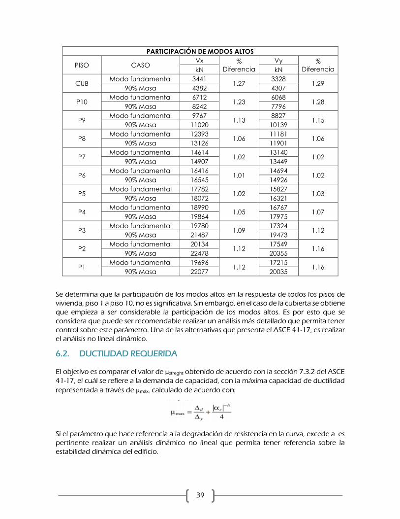
PARTICIPACIÓN DE MODOS ALTOS
PISO CASO Vx %
Diferencia
Vy %
Diferencia kN kN
CUB Modo fundamental 3441
1.27 3328
1.29 90% Masa 4382 4307
P10 Modo fundamental 6712
1.23 6068
1.28 90% Masa 8242 7796
P9 Modo fundamental 9767
1.13 8827
1.15 90% Masa 11020 10139
P8 Modo fundamental 12393
1.06 11181
1.06 90% Masa 13126 11901
P7 Modo fundamental 14614
1.02 13140
1.02 90% Masa 14907 13449
P6 Modo fundamental 16416
1.01 14694
1.02 90% Masa 16545 14926
P5 Modo fundamental 17782
1.02 15827
1.03 90% Masa 18072 16321
P4 Modo fundamental 18990
1.05 16767
1.07 90% Masa 19864 17975
P3 Modo fundamental 19780
1.09 17324
1.12 90% Masa 21487 19473
P2 Modo fundamental 20134
1.12 17549
1.16 90% Masa 22478 20355
P1 Modo fundamental 19696
1.12 17215
1.16 90% Masa 22077 20035
Se determina que la participación de los modos altos en la respuesta de todos los pisos de
vivienda, piso 1 a piso 10, no es significativa. Sin embargo, en el caso de la cubierta se obtiene
que empieza a ser considerable la participación de los modos altos. Es por esto que se
considera que puede ser recomendable realizar un análisis más detallado que permita tener
control sobre este parámetro. Una de las alternativas que presenta el ASCE 41-17, es realizar
el análisis no lineal dinámico.
6.2. DUCTILIDAD REQUERIDA
El objetivo es comparar el valor de μstreght obtenido de acuerdo con la sección 7.3.2 del ASCE
41-17, el cuál se refiere a la demanda de capacidad, con la máxima capacidad de ductilidad
representada a través de μmáx, calculado de acuerdo con:
Si el parámetro que hace referencia a la degradación de resistencia en la curva, excede a es
pertinente realizar un análisis dinámico no lineal que permita tener referencia sobre la
estabilidad dinámica del edificio.

40
7. NIVEL DE DESEMPEÑO Y MECANISMOS DE COLAPSO
El manual ASCE 41-17, presenta los niveles de desempeño y criterios de aceptación
establecido en el análisis de una estructura. Estos niveles se encuentran relacionados con
puntos de control sobre la curva de capacidad de la estructura y dependen de las
características de la edificación. Se pueden clasificar en tres categorías dependiendo del
grado de daño producto de la ocurrencia de fuerzas laterales producidas en caso de
ocurrencia de un evento sísmico.
OCUPACIÓN INMEDIADA (IO): Se presentan fisuras menores, no se evidencia daño
considerable en los elementos, la deriva permanente puede considerarse despreciable y la
estructura de conserva segura para ocupar.
SEGURIDAD DE LA VIDA (LS): Presencia de agrietamiento y aplastamiento en zonas de
borde de los muros, se presenta deriva permanente y daños notables en elementos no
estructurales. Se conserva un margen de seguridad ante el colapso parcial o total.
PREVENCIÓN DEL COLAPSO (CP): Daños severos en zonas de borde de los muros, presencia
de grietas, aplastamiento excesivo y pandeo del refuerzo longitudinal, deriva substancial y
permanente. Afectación considerable y generalizada e elementos estructurales,
degradación importante de resistencia y rigidez. La estructura está en capacidad de soportar
cargas gravitacionales, pero no se conserva un margen de seguridad ante el colapso.
Teniendo en cuenta los límites según el tipo de elemento se determinó en qué condiciones
se encuentran
Sentido μst ren μmax
X 2.83 3.26
Y 2.20 2.72
41
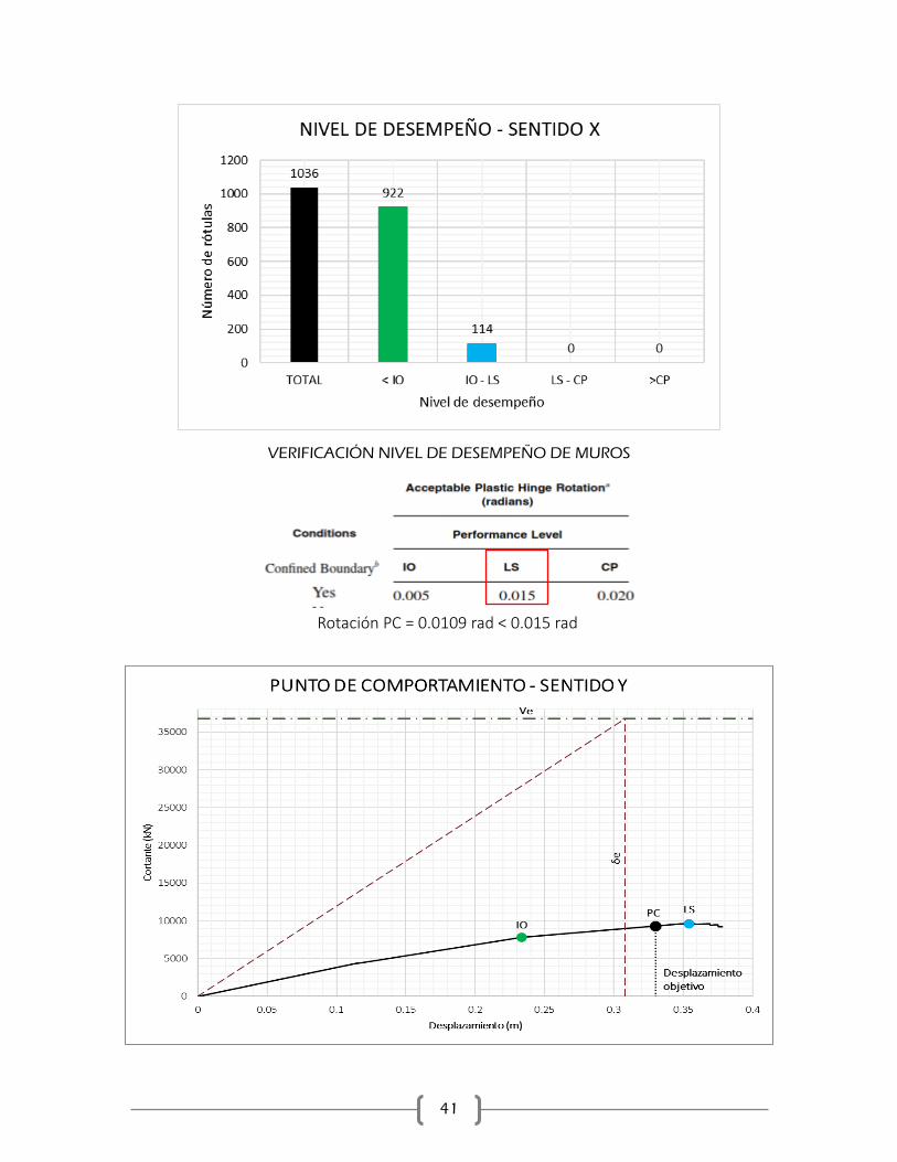
VERIFICACIÓN NIVEL DE DESEMPEÑO DE MUROS
Rotación PC = 0.0109 rad < 0.015 rad
42
.
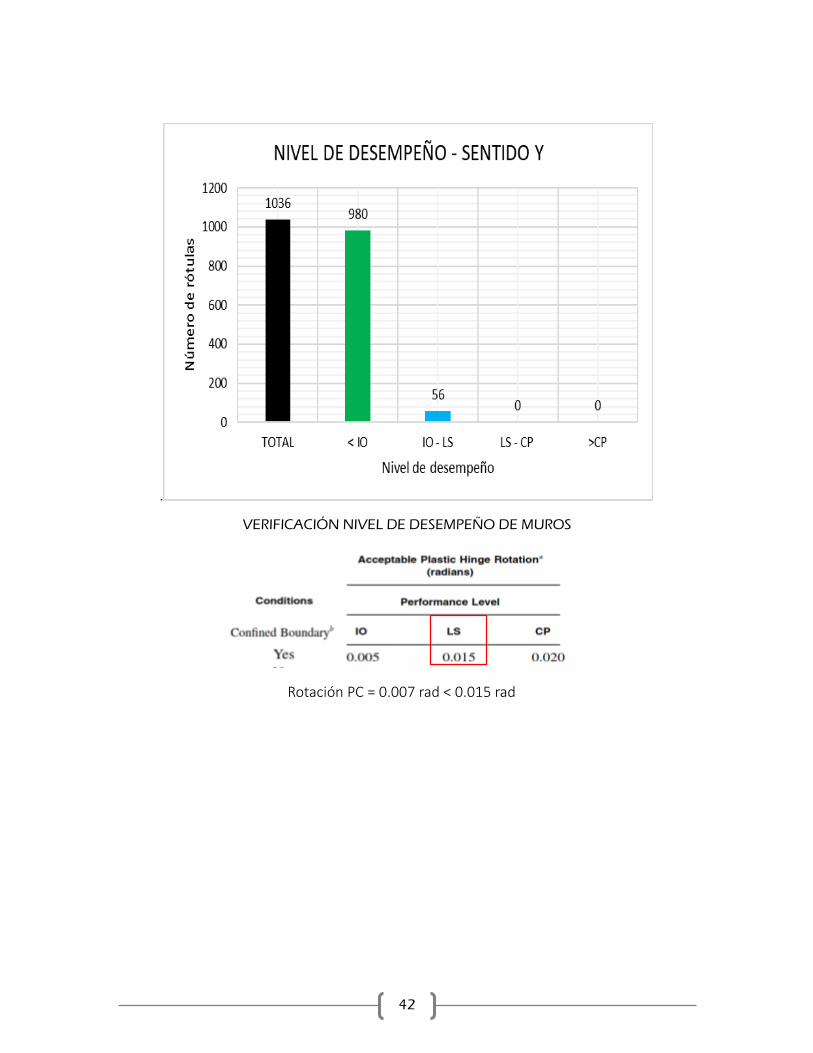
VERIFICACIÓN NIVEL DE DESEMPEÑO DE MUROS
Rotación PC = 0.007 rad < 0.015 rad

43
8. MODIFICACIONES AL DISEÑO ORIGINAL
CORTANTE EN MUROS
N C D D/C
6.05 2266.0 2556.24 1.13
3.15 2266.0 2556.24 1.13
44
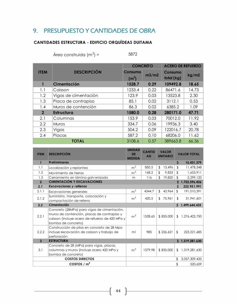
9. PRESUPUESTO Y CANTIDADES DE OBRA
CANTIDADES ESTRUCTURA - EDIFICIO ORQUÍDEAS DUITAMA
Área construida (m2) = 5872
Consumo
(m3)
m3/m2Consumo
total (kg)kg/m2
1 Cimentación 1528.7 0.29 109492.8 18.65
1.1 Caisson 1233.4 0.22 86471.6 14.73
1.2 Vigas de cimentación 123.9 0.03 13523.8 2.30
1.3 Placa de contrapiso 85.1 0.02 3112.1 0.53
1.4 Muros de contención 86.3 0.02 6385.2 1.09
2 Estructura 1580.0 0.28 280171.0 47.71
2.1 Columnas 153.9 0.03 70012.0 11.92
2.2 Muros 334.7 0.06 19936.3 3.40
2.3 Vigas 504.2 0.09 122016.7 20.78
2.4 Placas 587.2 0.10 68206.0 11.62
3108.6 0.57 389663.8 66.36
DESCRIPCIÓNITEM
CONCRETO ACERO DE REFUERZO
TOTAL
ITEM DESCRIPCIÓN
UNIDAD
DE
MEDIDA
CANTID
AD
VALOR
UNITARIOVALOR TOTAL
1 Preliminares 15,431,379$
1.1 Localización y replanteo m2 850.5 13,496$ 11,478,348$
1.2 Movimiento de tierras m3 168.2 9,833$ 1,653,911$
1.3 Cerramiento en lámina galvanizada m 116 19,820$ 2,299,120$
2 CIMENTACIÓN Y EXCAVACIONES 1,722,596,426$
2.1 Excavaciones y rellenos 222,951,991$
2.1.1 Excavaciones generales m3 4344.7 43,964$ 191,010,391$
2.1.2Suministro, transporte, colocación y
compactación de rellenom3 420.5 75,961$ 31,941,601$
2.2 Cimentación 1,499,644,435$
2.2.1
Concreto (28MPa) para vigas de cimentación,
muros de contención, placas de contrapiso y
caisson (incluye acero de refuerzo de 420 MPa y
bomba de concreto)
m3 1528.65 835,000$ 1,276,422,750$
2.2.2
Construcción de pilas en concreto de 28 Mpa
incluye excavación de caisson y trabajo de
perforación
ml 985 226,621$ 223,221,685$
3 ESTRUCTURA 1,319,281,630$
3.1
Concreto de 28 (MPa) para vigas, placas,
columnas y muros (incluye acero 420 MPa y
bomba de concreto)
m3 1579.98 835,000$ 1,319,281,630$
3,057,309,435$
520,659$
COSTOS DIRECTOS
COSTOS / m2

45
10. CONCLUSIONES
Para el caso particular de la estructura analizada, los efectos P-Delta no afectan en gran
medida en comportamiento de la estructura. Es posible evidenciar en las curvas de
comportamiento que al comparar el análisis sin considerar y considerando los efectos de
segundo orden el resultado es muy similar.
En cuanto a la influencia de considerar la flexibilidad de la cimentación se pudo observar
que los resultados iniciales corresponden con una pendiente menor en el rango elástico los
que se traduce en menor rigidez. Sin embargo, una vez se llega a la fluencia se observa
mayores valores de resistencia que si no se consideran los efectos de flexibilidad de la
cimentación.
El nivel de desempeño de la estructura en el punto de comportamiento se encuentra en LS,
lo que es consistente con las consideraciones tenidas en cuenta para diseño de acuerdo con
el NSR-10.
Las demandas de cortante de los muros para la estructura en el punto comportamiento son
mayores a las capacidades obtenidas con el refuerzo de acuerdo con las condiciones de
diseño.
Los efectos asociados a la no linealidad geométrica sobre la estructura presentan una
reducción inferior al 10% en relación con la capacidad. Este resultado esta relacionado con
las consideraciones utilizadas en diseño respecto al índice de estabilidad Q, el cual relaciona
el peso de la estructura con la fuerza cortante de piso.
El desplazamiento asociado al punto de comportamiento o desempeño, es superior al
desplazamiento elástico de cubierta. Sin embargo, este los valores se encuentran cercanos.
Se encuentra que para las dos direcciones principales de la estructura el mecanismo de falla
principal es el de las vigas.
46
REFERENCIAS
ACI 318-14. Building Code Requirements for sructural concrete, 2014.
Bertero, V. (2009). Earthquake engineering: From Engineering seismology to performance
based. (F. edition, Ed.)
Fanella, D. (2015). Reinforced concrete structures: analysis and design (Second Edition ed.).
Mc Graw Hill.
Park, R., & Paulay, T. (1975). Reinforced concrete structures. United States: John Wiley &
Sons.
Moehle. (2016). Seismic design of reinforced concrete building. Mc Graw Hill.
NSR-10. Reglamento colombiano de construcción sismo resistente. (2012).
NIST GCR 12-917-21. Soil-Structure Interaction for Building Structures. (2012).
CSI Analysis Reference Manual. For SAP2000, ETABS, SAFE and CSiBridge.
ASCE 41-17.
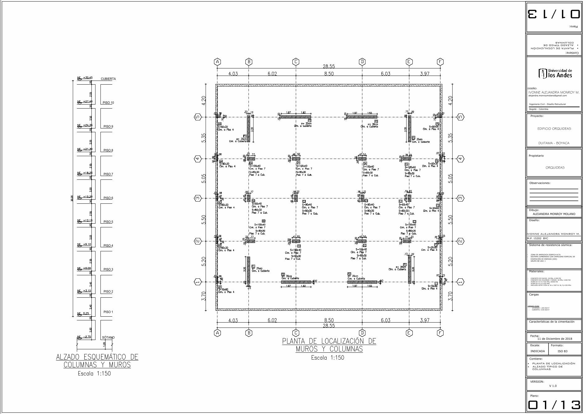
SÓTANO
PISO 1
PISO 2
PISO 3
PISO 4
PISO 5
PISO 6
PISO 7
PISO 8
PISO 9
PISO 10
CUBIERTA
Plano:
Observaciones:
Contiene:
Diseño:
Escala:
Fecha:
INDICADA
Formato:
ISO B3
Ingenieria Civil - Diseño Estructural
Bogotá - Colombia
Dibujo:
Contiene:
Plano:
Materiales:
Sistema de resistencia sísmica:
- ZONA DE AMENZAZA SISMICA ALTA
- SISTEMA COMBINADO CON CAPACIDAD ESPECIAL DE
DISIPACIÓN DE ENERGÍA (DES)
- GRUPO DE USO: I
VERSION:
V 1.0
01/1301/13
IVONNE ALEJANDRA MONROY M.
M.P. 15202 BYC
IVONNE ALEJANDRA MONROY M.DISEÑO:
· PLANTA DE LOCALIZACIÓN· ALZADO TÍPICO DE
COLUMNAS
·PLANTA DE LOCALIZACIÓN·ALZADO TÍPICO DE
COLUMNAS
Proyecto:
Propietario
EDIFICIO ORQUIDEAS
ALEJANDRA MONROY MOLANO
- CONCRETO DE PLACAS: 28 MPa, 4.000 PSI
- CONCRETO DE COLUMNAS Y MUROS: 28 MPa, 4.000 PSI
- ACERO Ø>#2 f'y=420 MPa, 60000 PSI
- ACERO Ø<#2 f'y=420 MPa
- ANCLAJES ASTM F1554 Gr 36 o 3307 Gr 36, Fy=250 MPa
Cargas
Características de la cimentación
11 de Diciembre de 2018
CARGAS VIVAS
- VIVIENDA: 1.80 kN/m²
- CUBIERTA: 5.00 kN/m²
DUITAMA - BOYACA
ORQUIDEAS
AutoCAD SHX Text
S=60x30
AutoCAD SHX Text
S=60x30
AutoCAD SHX Text
S=60x30
AutoCAD SHX Text
S=60x30
AutoCAD SHX Text
S=60x30
AutoCAD SHX Text
S=30x60
AutoCAD SHX Text
S=60x30
AutoCAD SHX Text
S=30x60
AutoCAD SHX Text
S=30x60
AutoCAD SHX Text
S=30x60
AutoCAD SHX Text
A5
AutoCAD SHX Text
F5
AutoCAD SHX Text
A4
AutoCAD SHX Text
F4
AutoCAD SHX Text
F3
AutoCAD SHX Text
A3
AutoCAD SHX Text
A2
AutoCAD SHX Text
F2
AutoCAD SHX Text
F1
AutoCAD SHX Text
A1
AutoCAD SHX Text
E4
AutoCAD SHX Text
C4
AutoCAD SHX Text
D4
AutoCAD SHX Text
e= 35cm
AutoCAD SHX Text
P1
AutoCAD SHX Text
e= 35cm
AutoCAD SHX Text
P2
AutoCAD SHX Text
Cim. a Cubierta
AutoCAD SHX Text
Cim. a Cubierta
AutoCAD SHX Text
Cim. a Piso 4
AutoCAD SHX Text
Cim. a Piso 4
AutoCAD SHX Text
Cim. a Piso 4
AutoCAD SHX Text
Cim. a Piso 4
AutoCAD SHX Text
Cim. a Piso 4
AutoCAD SHX Text
Cim. a Piso 4
AutoCAD SHX Text
Cim. a Piso 4
AutoCAD SHX Text
Cim. a Piso 4
AutoCAD SHX Text
Cim. a Piso 4
AutoCAD SHX Text
Cim. a Piso 4
AutoCAD SHX Text
e= 35cm
AutoCAD SHX Text
P2
AutoCAD SHX Text
Cim. a Cubierta
AutoCAD SHX Text
e= 35cm
AutoCAD SHX Text
P1
AutoCAD SHX Text
Cim. a Cubierta
AutoCAD SHX Text
B4
AutoCAD SHX Text
S=100x40
AutoCAD SHX Text
Cim. a Piso 7
AutoCAD SHX Text
S=90x40
AutoCAD SHX Text
B3
AutoCAD SHX Text
C3
AutoCAD SHX Text
D3
AutoCAD SHX Text
E3
AutoCAD SHX Text
E2
AutoCAD SHX Text
C2
AutoCAD SHX Text
D2
AutoCAD SHX Text
B2
AutoCAD SHX Text
e= 35cm
AutoCAD SHX Text
P1
AutoCAD SHX Text
Cim. a Cubierta
AutoCAD SHX Text
e= 35cm
AutoCAD SHX Text
P2
AutoCAD SHX Text
Cim. a Cubierta
AutoCAD SHX Text
e= 35cm
AutoCAD SHX Text
P2
AutoCAD SHX Text
Cim. a Cubierta
AutoCAD SHX Text
e= 35cm
AutoCAD SHX Text
P1
AutoCAD SHX Text
Cim. a Cubierta
AutoCAD SHX Text
A
AutoCAD SHX Text
B
AutoCAD SHX Text
C
AutoCAD SHX Text
D
AutoCAD SHX Text
E
AutoCAD SHX Text
F
AutoCAD SHX Text
PLANTA DE LOCALIZACIÓN DE MUROS Y COLUMNAS
AutoCAD SHX Text
Escala 1:150
AutoCAD SHX Text
5
AutoCAD SHX Text
4
AutoCAD SHX Text
3
AutoCAD SHX Text
2
AutoCAD SHX Text
1
AutoCAD SHX Text
5
AutoCAD SHX Text
4
AutoCAD SHX Text
3
AutoCAD SHX Text
2
AutoCAD SHX Text
1
AutoCAD SHX Text
A
AutoCAD SHX Text
B
AutoCAD SHX Text
C
AutoCAD SHX Text
D
AutoCAD SHX Text
E
AutoCAD SHX Text
F
AutoCAD SHX Text
S=80x30
AutoCAD SHX Text
Piso 7 a Cub.
AutoCAD SHX Text
S=100x40
AutoCAD SHX Text
Cim. a Piso 7
AutoCAD SHX Text
S=80x30
AutoCAD SHX Text
Piso 7 a Cub.
AutoCAD SHX Text
S=100x40
AutoCAD SHX Text
Cim. a Piso 7
AutoCAD SHX Text
S=80x30
AutoCAD SHX Text
Piso 7 a Cub.
AutoCAD SHX Text
S=100x40
AutoCAD SHX Text
Cim. a Piso 7
AutoCAD SHX Text
S=80x30
AutoCAD SHX Text
Piso 7 a Cub.
AutoCAD SHX Text
Cim. a Piso 7
AutoCAD SHX Text
S=80x30
AutoCAD SHX Text
Piso 7 a Cub.
AutoCAD SHX Text
S=90x40
AutoCAD SHX Text
Cim. a Piso 7
AutoCAD SHX Text
S=80x30
AutoCAD SHX Text
Piso 7 a Cub.
AutoCAD SHX Text
S=90x40
AutoCAD SHX Text
Cim. a Piso 7
AutoCAD SHX Text
S=80x30
AutoCAD SHX Text
Piso 7 a Cub.
AutoCAD SHX Text
S=90x40
AutoCAD SHX Text
Cim. a Piso 7
AutoCAD SHX Text
S=80x30
AutoCAD SHX Text
Piso 7 a Cub.
AutoCAD SHX Text
S=100x40
AutoCAD SHX Text
Cim. a Piso 7
AutoCAD SHX Text
S=80x30
AutoCAD SHX Text
Piso 7 a Cub.
AutoCAD SHX Text
S=100x40
AutoCAD SHX Text
Cim. a Piso 7
AutoCAD SHX Text
S=80x30
AutoCAD SHX Text
Piso 7 a Cub.
AutoCAD SHX Text
S=100x40
AutoCAD SHX Text
Cim. a Piso 7
AutoCAD SHX Text
S=80x30
AutoCAD SHX Text
Piso 7 a Cub.
AutoCAD SHX Text
S=100x40
AutoCAD SHX Text
Cim. a Piso 7
AutoCAD SHX Text
S=80x30
AutoCAD SHX Text
Piso 7 a Cub.
AutoCAD SHX Text
-2.75
AutoCAD SHX Text
NE.
AutoCAD SHX Text
+3.15
AutoCAD SHX Text
NE.
AutoCAD SHX Text
+6.05
AutoCAD SHX Text
NE.
AutoCAD SHX Text
+9.10
AutoCAD SHX Text
NE.
AutoCAD SHX Text
+12.15
AutoCAD SHX Text
NE.
AutoCAD SHX Text
+15.20
AutoCAD SHX Text
NE.
AutoCAD SHX Text
+18.25
AutoCAD SHX Text
NE.
AutoCAD SHX Text
+21.30
AutoCAD SHX Text
NE.
AutoCAD SHX Text
+24.35
AutoCAD SHX Text
NE.
AutoCAD SHX Text
+27.40
AutoCAD SHX Text
NE.
AutoCAD SHX Text
+30.45
AutoCAD SHX Text
NE.
AutoCAD SHX Text
0.25
AutoCAD SHX Text
NE.
AutoCAD SHX Text
ALZADO ESQUEMÁTICO DE COLUMNAS Y MUROS
AutoCAD SHX Text
Escala 1:150
NE + 0.25 m
NE -2.75 m
NE -2.95 m
NE -3.25 m
Plano:
Observaciones:
Contiene:
Diseño:
Escala:
Fecha:
INDICADA
Formato:
ISO B3
Ingenieria Civil - Diseño Estructural
Bogotá - Colombia
Dibujo:
Contiene:
Plano:
Materiales:
Sistema de resistencia sísmica:
- ZONA DE AMENZAZA SISMICA ALTA
- SISTEMA COMBINADO CON CAPACIDAD ESPECIAL DE
DISIPACIÓN DE ENERGÍA (DES)
- GRUPO DE USO: I
VERSION:
V 1.0
02/1302/13
IVONNE ALEJANDRA MONROY M.
M.P. 15202 BYC
IVONNE ALEJANDRA MONROY M.DISEÑO:
· PLANTA DE LOCALIZACIÓNDE CAISSON
· PLANTA DE CIMENTACIÓN
·PLANTA DE LOCALIZACIÓNDE CAISSON
·PLANTA DE CIMENTACIÓN
Proyecto:
Propietario
EDIFICIO ORQUIDEAS
ALEJANDRA MONROY MOLANO
- CONCRETO DE PLACAS: 28 MPa, 4.000 PSI
- CONCRETO DE COLUMNAS Y MUROS: 28 MPa, 4.000 PSI
- ACERO Ø>#2 f'y=420 MPa, 60000 PSI
- ACERO Ø<#2 f'y=420 MPa
- ANCLAJES ASTM F1554 Gr 36 o 3307 Gr 36, Fy=250 MPa
Cargas
CARGAS VIVAS
- VIVIENDA: 1.80 kN/m²
- CUBIERTA: 5.00 kN/m²
DUITAMA - BOYACA
ORQUIDEAS
11 de Diciembre de 2018
AutoCAD SHX Text
A
AutoCAD SHX Text
B
AutoCAD SHX Text
C
AutoCAD SHX Text
D
AutoCAD SHX Text
E
AutoCAD SHX Text
F
AutoCAD SHX Text
5
AutoCAD SHX Text
4
AutoCAD SHX Text
3
AutoCAD SHX Text
2
AutoCAD SHX Text
1
AutoCAD SHX Text
5
AutoCAD SHX Text
4
AutoCAD SHX Text
3
AutoCAD SHX Text
2
AutoCAD SHX Text
1
AutoCAD SHX Text
A
AutoCAD SHX Text
B
AutoCAD SHX Text
C
AutoCAD SHX Text
D
AutoCAD SHX Text
E
AutoCAD SHX Text
F
AutoCAD SHX Text
PLANTA DE LOCALIZACIÓN DE CAISSON
AutoCAD SHX Text
Escala 1:150
AutoCAD SHX Text
TIPO 1
AutoCAD SHX Text
TIPO 1
AutoCAD SHX Text
TIPO 1
AutoCAD SHX Text
TIPO 1
AutoCAD SHX Text
TIPO 1
AutoCAD SHX Text
TIPO 1
AutoCAD SHX Text
TIPO 1
AutoCAD SHX Text
TIPO 1
AutoCAD SHX Text
TIPO 1
AutoCAD SHX Text
TIPO 1
AutoCAD SHX Text
TIPO 1
AutoCAD SHX Text
TIPO 1
AutoCAD SHX Text
TIPO 1
AutoCAD SHX Text
TIPO 1
AutoCAD SHX Text
TIPO 1
AutoCAD SHX Text
TIPO 1
AutoCAD SHX Text
TIPO 1
AutoCAD SHX Text
TIPO 1
AutoCAD SHX Text
TIPO 1
AutoCAD SHX Text
TIPO 1
AutoCAD SHX Text
TIPO 1
AutoCAD SHX Text
TIPO 1
AutoCAD SHX Text
TIPO 2
AutoCAD SHX Text
TIPO 2
AutoCAD SHX Text
TIPO 2
AutoCAD SHX Text
TIPO 2
AutoCAD SHX Text
TIPO 2
AutoCAD SHX Text
TIPO 2
AutoCAD SHX Text
TIPO 3
AutoCAD SHX Text
TIPO 3
AutoCAD SHX Text
TIPO 3
AutoCAD SHX Text
TIPO 3
AutoCAD SHX Text
TIPO 3
AutoCAD SHX Text
TIPO 3
AutoCAD SHX Text
%%UDETALLE TÍPICO DE CIMENTACIÓN
AutoCAD SHX Text
ESCALA 1 : 50
AutoCAD SHX Text
Placa de Contrapiso
AutoCAD SHX Text
Columna
AutoCAD SHX Text
Base granular
AutoCAD SHX Text
Viga de cimentación
AutoCAD SHX Text
Caisson
AutoCAD SHX Text
-2.75
AutoCAD SHX Text
Escala 1:25
AutoCAD SHX Text
REFUERZO MC1 t=0.25 m
AutoCAD SHX Text
#4 c/20
AutoCAD SHX Text
#3 c/20
AutoCAD SHX Text
ZARPA 1
AutoCAD SHX Text
#3 c/25
AutoCAD SHX Text
VSM
AutoCAD SHX Text
Viga sobre muro
AutoCAD SHX Text
.15
AutoCAD SHX Text
.15
AutoCAD SHX Text
#3 c/.20
AutoCAD SHX Text
.20
AutoCAD SHX Text
.20
AutoCAD SHX Text
#4 c/.20
AutoCAD SHX Text
L = 3.70 m
AutoCAD SHX Text
L = 3.80 m
AutoCAD SHX Text
CONTRAPISO
AutoCAD SHX Text
RECEBO
AutoCAD SHX Text
Placa de Contrapiso
AutoCAD SHX Text
Base granular
AutoCAD SHX Text
según estudio de suelos
AutoCAD SHX Text
6.0 mm c/.15
AutoCAD SHX Text
ambos sentidos
AutoCAD SHX Text
-2.75
AutoCAD SHX Text
%%UPLACA DE CONTRAPISO
AutoCAD SHX Text
ESCALA 1 : 50
Plano:
Observaciones:
Contiene:
Diseño:
Escala:
Fecha:
INDICADA
Formato:
ISO B3
Ingenieria Civil - Diseño Estructural
Bogotá - Colombia
Dibujo:
Contiene:
Plano:
Materiales:
Sistema de resistencia sísmica:
- ZONA DE AMENZAZA SISMICA ALTA
- SISTEMA COMBINADO CON CAPACIDAD ESPECIAL DE
DISIPACIÓN DE ENERGÍA (DES)
- GRUPO DE USO: I
VERSION:
V 1.0
03/1303/13
IVONNE ALEJANDRA MONROY M.
M.P. 15202 BYC
IVONNE ALEJANDRA MONROY M.DISEÑO:
· PLANTA DE CIMENTACIÓN· DETALLE TÍPICO DE CAISSON
·PLANTA DE CIMENTACIÓN·DETALLE TÍPICO DE
CAISSON
Proyecto:
Propietario
EDIFICIO ORQUIDEAS
ALEJANDRA MONROY MOLANO
- CONCRETO DE PLACAS: 28 MPa, 4.000 PSI
- CONCRETO DE COLUMNAS Y MUROS: 28 MPa, 4.000 PSI
- ACERO Ø>#2 f'y=420 MPa, 60000 PSI
- ACERO Ø<#2 f'y=420 MPa
- ANCLAJES ASTM F1554 Gr 36 o 3307 Gr 36, Fy=250 MPa
Cargas
Características de la cimentación
CARGAS VIVAS
- VIVIENDA: 1.80 kN/m²
- CUBIERTA: 5.00 kN/m²
DUITAMA - BOYACA
ORQUIDEAS
11 de Diciembre de 2018
AutoCAD SHX Text
A
AutoCAD SHX Text
B
AutoCAD SHX Text
C
AutoCAD SHX Text
D
AutoCAD SHX Text
E
AutoCAD SHX Text
F
AutoCAD SHX Text
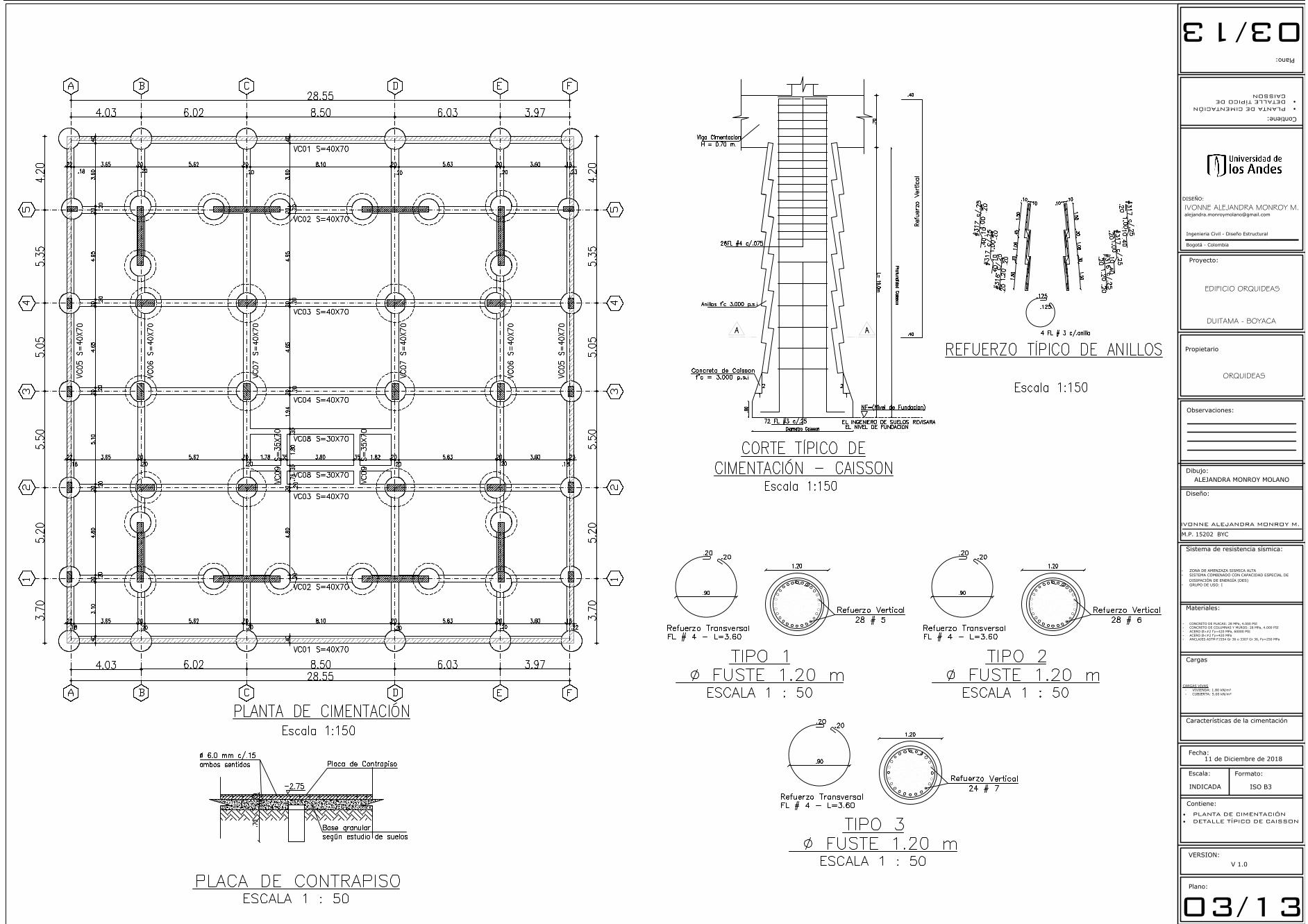
PLANTA DE CIMENTACIÓN
AutoCAD SHX Text
Escala 1:150
AutoCAD SHX Text
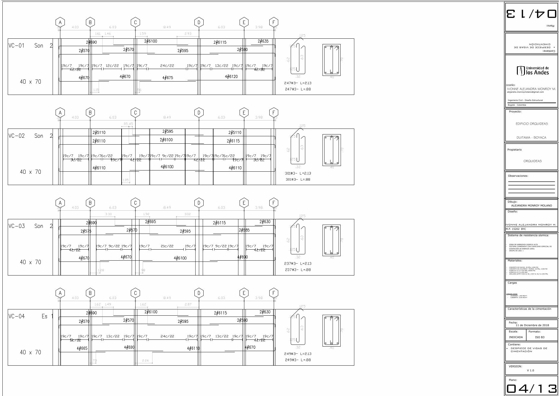
VC01 S=40X70
AutoCAD SHX Text
5
AutoCAD SHX Text
4
AutoCAD SHX Text
3
AutoCAD SHX Text
2
AutoCAD SHX Text
1
AutoCAD SHX Text
5
AutoCAD SHX Text
4
AutoCAD SHX Text
3
AutoCAD SHX Text
2
AutoCAD SHX Text
1
AutoCAD SHX Text
A
AutoCAD SHX Text
B
AutoCAD SHX Text
C
AutoCAD SHX Text
D
AutoCAD SHX Text
E
AutoCAD SHX Text
F
AutoCAD SHX Text
VC02 S=40X70
AutoCAD SHX Text
VC03 S=40X70
AutoCAD SHX Text
VC04 S=40X70
AutoCAD SHX Text
VC08 S=30X70
AutoCAD SHX Text
VC08 S=30X70
AutoCAD SHX Text
VC03 S=40X70
AutoCAD SHX Text
VC02 S=40X70
AutoCAD SHX Text
VC01 S=40X70
AutoCAD SHX Text
VC05 S=40X70
AutoCAD SHX Text
VC05 S=40X70
AutoCAD SHX Text
VC06 S=40X70
AutoCAD SHX Text
VC06 S=40X70
AutoCAD SHX Text
VC07 S=40X70
AutoCAD SHX Text
VC07 S=40X70
AutoCAD SHX Text
VC09 S=35X70
AutoCAD SHX Text
VC09 S=35X70
AutoCAD SHX Text
%%UNF=(Nivel de Fundacion)
AutoCAD SHX Text
EL NIVEL DE FUNDACION
AutoCAD SHX Text
EL INGENIERO DE SUELOS REVISARA
AutoCAD SHX Text
Anillos f'c 3.000 p.s.i.
AutoCAD SHX Text
Concreto de Caisson
AutoCAD SHX Text
f'c = 3.000 p.s.i
AutoCAD SHX Text
72 FL #3 c/.25
AutoCAD SHX Text
1
AutoCAD SHX Text
2
AutoCAD SHX Text
1
AutoCAD SHX Text
2
AutoCAD SHX Text
A
AutoCAD SHX Text
A
AutoCAD SHX Text
H = 0.70 m.
AutoCAD SHX Text
Viga Cimentacion
AutoCAD SHX Text
26FL #4 c/.075
AutoCAD SHX Text
Refuerzo Vertical
AutoCAD SHX Text
.40
AutoCAD SHX Text
.40
AutoCAD SHX Text
#316 c/.25
AutoCAD SHX Text
4 FL # 3 c/.anillo
AutoCAD SHX Text
#317 c/.25
AutoCAD SHX Text
.20
AutoCAD SHX Text
.40
AutoCAD SHX Text
.20
AutoCAD SHX Text
.10
AutoCAD SHX Text
#317 c/.25
AutoCAD SHX Text
#316 c/.25
AutoCAD SHX Text
1.20
AutoCAD SHX Text
.20
AutoCAD SHX Text
.10
AutoCAD SHX Text
.20
AutoCAD SHX Text
1.00
AutoCAD SHX Text
.40
AutoCAD SHX Text
1.00
AutoCAD SHX Text
.20
AutoCAD SHX Text
.125
AutoCAD SHX Text
.125
AutoCAD SHX Text
.20
AutoCAD SHX Text
1.20
AutoCAD SHX Text
.20
AutoCAD SHX Text
.10
AutoCAD SHX Text
#317 c/.25
AutoCAD SHX Text
1.00
AutoCAD SHX Text
.40
AutoCAD SHX Text
.20
AutoCAD SHX Text
#317 c/.25
AutoCAD SHX Text
.10
AutoCAD SHX Text
.40
AutoCAD SHX Text
1.00
AutoCAD SHX Text
CORTE TÍPICO DE CIMENTACIÓN - CAISSON
AutoCAD SHX Text
Escala 1:150
AutoCAD SHX Text
REFUERZO TÍPICO DE ANILLOS
AutoCAD SHX Text
Escala 1:150
AutoCAD SHX Text
Placa de Contrapiso
AutoCAD SHX Text
Base granular
AutoCAD SHX Text
según estudio de suelos
AutoCAD SHX Text
6.0 mm c/.15
AutoCAD SHX Text
ambos sentidos
AutoCAD SHX Text
-2.75
AutoCAD SHX Text
%%UPLACA DE CONTRAPISO
AutoCAD SHX Text
ESCALA 1 : 50
AutoCAD SHX Text
Refuerzo Vertical
AutoCAD SHX Text
28 # 5
AutoCAD SHX Text
.20
AutoCAD SHX Text
.20
AutoCAD SHX Text
Refuerzo Transversal
AutoCAD SHX Text
FL # 4 - L=3.60
AutoCAD SHX Text
%%U %%C FUSTE 1.20 m
AutoCAD SHX Text
ESCALA 1 : 50
AutoCAD SHX Text
%%UTIPO 1
AutoCAD SHX Text
Refuerzo Vertical
AutoCAD SHX Text
28 # 6
AutoCAD SHX Text
.20
AutoCAD SHX Text
.20
AutoCAD SHX Text
Refuerzo Transversal
AutoCAD SHX Text
FL # 4 - L=3.60
AutoCAD SHX Text
%%U %%C FUSTE 1.20 m
AutoCAD SHX Text
ESCALA 1 : 50
AutoCAD SHX Text
%%UTIPO 2
AutoCAD SHX Text
Refuerzo Vertical
AutoCAD SHX Text
24 # 7
AutoCAD SHX Text
.20
AutoCAD SHX Text
.20
AutoCAD SHX Text
Refuerzo Transversal
AutoCAD SHX Text
FL # 4 - L=3.60
AutoCAD SHX Text
%%U %%C FUSTE 1.20 m
AutoCAD SHX Text
ESCALA 1 : 50
AutoCAD SHX Text
%%UTIPO 3
Plano:
Observaciones:
Contiene:
Diseño:
Escala:
Fecha:
INDICADA
Formato:
ISO B3
Ingenieria Civil - Diseño Estructural
Bogotá - Colombia
Dibujo:
Contiene:
Plano:
Materiales:
Sistema de resistencia sísmica:
- ZONA DE AMENZAZA SISMICA ALTA
- SISTEMA COMBINADO CON CAPACIDAD ESPECIAL DE
DISIPACIÓN DE ENERGÍA (DES)
- GRUPO DE USO: I
VERSION:
V 1.0
04/1304/13
IVONNE ALEJANDRA MONROY M.
M.P. 15202 BYC
IVONNE ALEJANDRA MONROY M.DISEÑO:
· DESPIECE DE VIGAS DECIMENTACIÓN
·DESPIECE DE VIGAS DECIMENTACIÓN
Proyecto:
Propietario
EDIFICIO ORQUIDEAS
ALEJANDRA MONROY MOLANO
- CONCRETO DE PLACAS: 28 MPa, 4.000 PSI
- CONCRETO DE COLUMNAS Y MUROS: 28 MPa, 4.000 PSI
- ACERO Ø>#2 f'y=420 MPa, 60000 PSI
- ACERO Ø<#2 f'y=420 MPa
- ANCLAJES ASTM F1554 Gr 36 o 3307 Gr 36, Fy=250 MPa
Cargas
Características de la cimentación
CARGAS VIVAS
- VIVIENDA: 1.80 kN/m²
- CUBIERTA: 5.00 kN/m²
DUITAMA - BOYACA
ORQUIDEAS
11 de Diciembre de 2018
AutoCAD SHX Text
VC-01
AutoCAD SHX Text
Son 2
AutoCAD SHX Text
40 x 70
AutoCAD SHX Text
A
AutoCAD SHX Text
B
AutoCAD SHX Text
C
AutoCAD SHX Text
D
AutoCAD SHX Text
E
AutoCAD SHX Text
F
AutoCAD SHX Text
.22
AutoCAD SHX Text
4.03
AutoCAD SHX Text
6.03
AutoCAD SHX Text
8.49
AutoCAD SHX Text
6.03
AutoCAD SHX Text
3.98
AutoCAD SHX Text
.22
AutoCAD SHX Text
2#690
AutoCAD SHX Text
2#570
AutoCAD SHX Text
2#570
AutoCAD SHX Text
2#6100
AutoCAD SHX Text
2#595
AutoCAD SHX Text
2#6115
AutoCAD SHX Text
2#590
AutoCAD SHX Text
2#635
AutoCAD SHX Text
4#670
AutoCAD SHX Text
4#670
AutoCAD SHX Text
4#675
AutoCAD SHX Text
4#6120
AutoCAD SHX Text
.32
AutoCAD SHX Text
.125
AutoCAD SHX Text
.62
AutoCAD SHX Text
.125
AutoCAD SHX Text
.125
AutoCAD SHX Text
.63
AutoCAD SHX Text
247#3- L=2.13
AutoCAD SHX Text
247#3- L=.88
AutoCAD SHX Text
.40
AutoCAD SHX Text
.70
AutoCAD SHX Text
19c/7
AutoCAD SHX Text
4c/22
AutoCAD SHX Text
19c/7
AutoCAD SHX Text
19c/7
AutoCAD SHX Text
12c/22
AutoCAD SHX Text
19c/7
AutoCAD SHX Text
19c/7
AutoCAD SHX Text
24c/22
AutoCAD SHX Text
19c/7
AutoCAD SHX Text
19c/7
AutoCAD SHX Text
13c/22
AutoCAD SHX Text
19c/7
AutoCAD SHX Text
19c/7
AutoCAD SHX Text
4c/22
AutoCAD SHX Text
19c/7
AutoCAD SHX Text
1.15
AutoCAD SHX Text
.56
AutoCAD SHX Text
1.61
AutoCAD SHX Text
1.46
AutoCAD SHX Text
1.59
AutoCAD SHX Text
2.93
AutoCAD SHX Text
VC-02
AutoCAD SHX Text
Son 2
AutoCAD SHX Text
40 x 70
AutoCAD SHX Text
A
AutoCAD SHX Text
B
AutoCAD SHX Text
C
AutoCAD SHX Text
D
AutoCAD SHX Text
E
AutoCAD SHX Text
F
AutoCAD SHX Text
.22
AutoCAD SHX Text
4.03
AutoCAD SHX Text
6.03
AutoCAD SHX Text
8.49
AutoCAD SHX Text
6.03
AutoCAD SHX Text
3.98
AutoCAD SHX Text
.23
AutoCAD SHX Text
2#5110
AutoCAD SHX Text
2#6110
AutoCAD SHX Text
2#6100
AutoCAD SHX Text
2#595
AutoCAD SHX Text
2#6115
AutoCAD SHX Text
2#5110
AutoCAD SHX Text
4#6110
AutoCAD SHX Text
4#6100
AutoCAD SHX Text
4#6110
AutoCAD SHX Text
.32
AutoCAD SHX Text
.125
AutoCAD SHX Text
.62
AutoCAD SHX Text
.125
AutoCAD SHX Text
.125
AutoCAD SHX Text
.63
AutoCAD SHX Text
301#3- L=2.13
AutoCAD SHX Text
301#3- L=.88
AutoCAD SHX Text
.40
AutoCAD SHX Text
.70
AutoCAD SHX Text
19c/7
AutoCAD SHX Text
3c/22
AutoCAD SHX Text
19c/7
AutoCAD SHX Text
19c/7
AutoCAD SHX Text
6c/22
AutoCAD SHX Text
19c/7
AutoCAD SHX Text
19c/7
AutoCAD SHX Text
4c/22
AutoCAD SHX Text
19c/7
AutoCAD SHX Text
19c/7
AutoCAD SHX Text
9c/22
AutoCAD SHX Text
19c/7
AutoCAD SHX Text
19c/7
AutoCAD SHX Text
4c/22
AutoCAD SHX Text
19c/7
AutoCAD SHX Text
19c/7
AutoCAD SHX Text
6c/22
AutoCAD SHX Text
19c/7
AutoCAD SHX Text
19c/7
AutoCAD SHX Text
3c/22
AutoCAD SHX Text
19c/7
AutoCAD SHX Text
1.05
AutoCAD SHX Text
.95
AutoCAD SHX Text
.45
AutoCAD SHX Text
VC-03
AutoCAD SHX Text
Son 2
AutoCAD SHX Text
40 x 70
AutoCAD SHX Text
A
AutoCAD SHX Text
B
AutoCAD SHX Text
C
AutoCAD SHX Text
D
AutoCAD SHX Text
E
AutoCAD SHX Text
F
AutoCAD SHX Text
.22
AutoCAD SHX Text
4.03
AutoCAD SHX Text
6.03
AutoCAD SHX Text
8.49
AutoCAD SHX Text
6.03
AutoCAD SHX Text
3.98
AutoCAD SHX Text
.22
AutoCAD SHX Text
2#690
AutoCAD SHX Text
2#575
AutoCAD SHX Text
2#570
AutoCAD SHX Text
2#695
AutoCAD SHX Text
2#595
AutoCAD SHX Text
2#6115
AutoCAD SHX Text
2#585
AutoCAD SHX Text
2#630
AutoCAD SHX Text
4#670
AutoCAD SHX Text
4#670
AutoCAD SHX Text
4#6100
AutoCAD SHX Text
4#690
AutoCAD SHX Text
.32
AutoCAD SHX Text
.125
AutoCAD SHX Text
.62
AutoCAD SHX Text
.125
AutoCAD SHX Text
.125
AutoCAD SHX Text
.63
AutoCAD SHX Text
237#3- L=2.13
AutoCAD SHX Text
237#3- L=.88
AutoCAD SHX Text
.40
AutoCAD SHX Text
.70
AutoCAD SHX Text
19c/7
AutoCAD SHX Text
4c/22
AutoCAD SHX Text
19c/7
AutoCAD SHX Text
19c/7
AutoCAD SHX Text
9c/22
AutoCAD SHX Text
19c/7
AutoCAD SHX Text
19c/7
AutoCAD SHX Text
21c/22
AutoCAD SHX Text
19c/7
AutoCAD SHX Text
19c/7
AutoCAD SHX Text
9c/22
AutoCAD SHX Text
19c/7
AutoCAD SHX Text
19c/7
AutoCAD SHX Text
4c/22
AutoCAD SHX Text
19c/7
AutoCAD SHX Text
1.28
AutoCAD SHX Text
.98
AutoCAD SHX Text
3.30
AutoCAD SHX Text
1.92
AutoCAD SHX Text
3.02
AutoCAD SHX Text
VC-04
AutoCAD SHX Text
Es 1
AutoCAD SHX Text
40 x 70
AutoCAD SHX Text
A
AutoCAD SHX Text
B
AutoCAD SHX Text
C
AutoCAD SHX Text
D
AutoCAD SHX Text
E
AutoCAD SHX Text
F
AutoCAD SHX Text
.22
AutoCAD SHX Text
4.03
AutoCAD SHX Text
6.03
AutoCAD SHX Text
8.49
AutoCAD SHX Text
6.03
AutoCAD SHX Text
3.98
AutoCAD SHX Text
.22
AutoCAD SHX Text
2#690
AutoCAD SHX Text
2#570
AutoCAD SHX Text
2#570
AutoCAD SHX Text
2#6100
AutoCAD SHX Text
2#595
AutoCAD SHX Text
2#6115
AutoCAD SHX Text
2#590
AutoCAD SHX Text
2#630
AutoCAD SHX Text
4#665
AutoCAD SHX Text
4#690
AutoCAD SHX Text
4#6110
AutoCAD SHX Text
4#670
AutoCAD SHX Text
.32
AutoCAD SHX Text
.125
AutoCAD SHX Text
.62
AutoCAD SHX Text
.125
AutoCAD SHX Text
.125
AutoCAD SHX Text
.63
AutoCAD SHX Text
249#3- L=2.13
AutoCAD SHX Text
249#3- L=.88
AutoCAD SHX Text
.40
AutoCAD SHX Text
.70
AutoCAD SHX Text
19c/7
AutoCAD SHX Text
5c/22
AutoCAD SHX Text
19c/7
AutoCAD SHX Text
19c/7
AutoCAD SHX Text
13c/22
AutoCAD SHX Text
19c/7
AutoCAD SHX Text
19c/7
AutoCAD SHX Text
24c/22
AutoCAD SHX Text
19c/7
AutoCAD SHX Text
19c/7
AutoCAD SHX Text
13c/22
AutoCAD SHX Text
19c/7
AutoCAD SHX Text
19c/7
AutoCAD SHX Text
4c/22
AutoCAD SHX Text
19c/7
AutoCAD SHX Text
.73
AutoCAD SHX Text
2.26
AutoCAD SHX Text
1.62
AutoCAD SHX Text
1.49
AutoCAD SHX Text
1.62
AutoCAD SHX Text
2.87

Plano:
Observaciones:
Contiene:
Diseño:
Escala:
Fecha:
INDICADA
Formato:
ISO B3
Ingenieria Civil - Diseño Estructural
Bogotá - Colombia
Dibujo:
Contiene:
Plano:
Materiales:
Sistema de resistencia sísmica:
- ZONA DE AMENZAZA SISMICA ALTA
- SISTEMA COMBINADO CON CAPACIDAD ESPECIAL DE
DISIPACIÓN DE ENERGÍA (DES)
- GRUPO DE USO: I
VERSION:
V 1.0
05/1305/13
IVONNE ALEJANDRA MONROY M.
M.P. 15202 BYC
IVONNE ALEJANDRA MONROY M.DISEÑO:
· DESPIECE DE VIGAS DECIMENTACIÓN
·DESPIECE DE VIGAS DECIMENTACIÓN
Proyecto:
Propietario
EDIFICIO ORQUIDEAS
ALEJANDRA MONROY MOLANO
- CONCRETO DE PLACAS: 28 MPa, 4.000 PSI
- CONCRETO DE COLUMNAS Y MUROS: 28 MPa, 4.000 PSI
- ACERO Ø>#2 f'y=420 MPa, 60000 PSI
- ACERO Ø<#2 f'y=420 MPa
- ANCLAJES ASTM F1554 Gr 36 o 3307 Gr 36, Fy=250 MPa
Cargas
Características de la cimentación
CARGAS VIVAS
- VIVIENDA: 1.80 kN/m²
- CUBIERTA: 5.00 kN/m²
DUITAMA - BOYACA
ORQUIDEAS
11 de Diciembre de 2018
AutoCAD SHX Text
VC-05
AutoCAD SHX Text
Son 2
AutoCAD SHX Text
40 x 70
AutoCAD SHX Text
1
AutoCAD SHX Text
2
AutoCAD SHX Text
3
AutoCAD SHX Text
4
AutoCAD SHX Text
5
AutoCAD SHX Text
3.70
AutoCAD SHX Text
5.20
AutoCAD SHX Text
5.50
AutoCAD SHX Text
5.05
AutoCAD SHX Text
5.35
AutoCAD SHX Text
4.20
AutoCAD SHX Text
2#5120
AutoCAD SHX Text
2#675
AutoCAD SHX Text
2#6120
AutoCAD SHX Text
2#5115
AutoCAD SHX Text
2#6105
AutoCAD SHX Text
2#580
AutoCAD SHX Text
2#635
AutoCAD SHX Text
4#6120
AutoCAD SHX Text
4#6120
AutoCAD SHX Text
4#680
AutoCAD SHX Text
.32
AutoCAD SHX Text
.125
AutoCAD SHX Text
.62
AutoCAD SHX Text
.125
AutoCAD SHX Text
.125
AutoCAD SHX Text
.63
AutoCAD SHX Text
269#3- L=2.13
AutoCAD SHX Text
269#3- L=.88
AutoCAD SHX Text
.40
AutoCAD SHX Text
.70
AutoCAD SHX Text
19c/7
AutoCAD SHX Text
1
AutoCAD SHX Text
19c/7
AutoCAD SHX Text
19c/7
AutoCAD SHX Text
8c/22
AutoCAD SHX Text
19c/7
AutoCAD SHX Text
19c/7
AutoCAD SHX Text
10c/22
AutoCAD SHX Text
19c/7
AutoCAD SHX Text
19c/7
AutoCAD SHX Text
8c/22
AutoCAD SHX Text
19c/7
AutoCAD SHX Text
19c/7
AutoCAD SHX Text
10c/22
AutoCAD SHX Text
19c/7
AutoCAD SHX Text
19c/7
AutoCAD SHX Text
4c/22
AutoCAD SHX Text
19c/7
AutoCAD SHX Text
1.65
AutoCAD SHX Text
2.18
AutoCAD SHX Text
1.80
AutoCAD SHX Text
2.23
AutoCAD SHX Text
VC-06
AutoCAD SHX Text
Son 2
AutoCAD SHX Text
40 x 70
AutoCAD SHX Text
1
AutoCAD SHX Text
2
AutoCAD SHX Text
3
AutoCAD SHX Text
4
AutoCAD SHX Text
5
AutoCAD SHX Text
3.70
AutoCAD SHX Text
5.20
AutoCAD SHX Text
5.50
AutoCAD SHX Text
5.05
AutoCAD SHX Text
5.35
AutoCAD SHX Text
4.20
AutoCAD SHX Text
2#5120
AutoCAD SHX Text
2#670
AutoCAD SHX Text
2#6120
AutoCAD SHX Text
2#5110
AutoCAD SHX Text
2#6110
AutoCAD SHX Text
2#590
AutoCAD SHX Text
2#635
AutoCAD SHX Text
4#665
AutoCAD SHX Text
4#675
AutoCAD SHX Text
4#6115
AutoCAD SHX Text
4#675
AutoCAD SHX Text
.32
AutoCAD SHX Text
.125
AutoCAD SHX Text
.62
AutoCAD SHX Text
.125
AutoCAD SHX Text
.125
AutoCAD SHX Text
.63
AutoCAD SHX Text
310#3- L=2.13
AutoCAD SHX Text
310#3- L=.88
AutoCAD SHX Text
.40
AutoCAD SHX Text
.70
AutoCAD SHX Text
19c/7
AutoCAD SHX Text
1
AutoCAD SHX Text
19c/7
AutoCAD SHX Text
19c/7
AutoCAD SHX Text
3c/22
AutoCAD SHX Text
19c/7
AutoCAD SHX Text
25c/7
AutoCAD SHX Text
19c/7
AutoCAD SHX Text
10c/22
AutoCAD SHX Text
19c/7
AutoCAD SHX Text
19c/7
AutoCAD SHX Text
8c/22
AutoCAD SHX Text
19c/7
AutoCAD SHX Text
28c/7
AutoCAD SHX Text
19c/7
AutoCAD SHX Text
3c/22
AutoCAD SHX Text
19c/7
AutoCAD SHX Text
19c/7
AutoCAD SHX Text
4c/22
AutoCAD SHX Text
19c/7
AutoCAD SHX Text
1.65
AutoCAD SHX Text
2.55
AutoCAD SHX Text
1.35
AutoCAD SHX Text
1.66
AutoCAD SHX Text
1.77
AutoCAD SHX Text
VC-07
AutoCAD SHX Text
Son 2
AutoCAD SHX Text
40 x 70
AutoCAD SHX Text
1
AutoCAD SHX Text
2
AutoCAD SHX Text
3
AutoCAD SHX Text
4
AutoCAD SHX Text
5
AutoCAD SHX Text
3.70
AutoCAD SHX Text
5.20
AutoCAD SHX Text
5.50
AutoCAD SHX Text
5.05
AutoCAD SHX Text
5.35
AutoCAD SHX Text
4.20
AutoCAD SHX Text
2#5120
AutoCAD SHX Text
2#675
AutoCAD SHX Text
2#6120
AutoCAD SHX Text
2#5115
AutoCAD SHX Text
2#6105
AutoCAD SHX Text
2#580
AutoCAD SHX Text
2#635
AutoCAD SHX Text
4#6115
AutoCAD SHX Text
4#6120
AutoCAD SHX Text
4#685
AutoCAD SHX Text
.32
AutoCAD SHX Text
.125
AutoCAD SHX Text
.62
AutoCAD SHX Text
.125
AutoCAD SHX Text
.125
AutoCAD SHX Text
.63
AutoCAD SHX Text
270#3- L=2.13
AutoCAD SHX Text
270#3- L=.88
AutoCAD SHX Text
.40
AutoCAD SHX Text
.70
AutoCAD SHX Text
19c/7
AutoCAD SHX Text
1
AutoCAD SHX Text
19c/7
AutoCAD SHX Text
19c/7
AutoCAD SHX Text
9c/22
AutoCAD SHX Text
19c/7
AutoCAD SHX Text
19c/7
AutoCAD SHX Text
10c/22
AutoCAD SHX Text
19c/7
AutoCAD SHX Text
19c/7
AutoCAD SHX Text
8c/22
AutoCAD SHX Text
19c/7
AutoCAD SHX Text
19c/7
AutoCAD SHX Text
10c/22
AutoCAD SHX Text
19c/7
AutoCAD SHX Text
19c/7
AutoCAD SHX Text
4c/22
AutoCAD SHX Text
19c/7
AutoCAD SHX Text
1.15
AutoCAD SHX Text
2.28
AutoCAD SHX Text
1.63
AutoCAD SHX Text
2.28
AutoCAD SHX Text
VC-08
AutoCAD SHX Text
Son 2
AutoCAD SHX Text
30 x 70
AutoCAD SHX Text
D
AutoCAD SHX Text
E
AutoCAD SHX Text
.20
AutoCAD SHX Text
8.50
AutoCAD SHX Text
.20
AutoCAD SHX Text
3#694
AutoCAD SHX Text
3#694
AutoCAD SHX Text
.22
AutoCAD SHX Text
.125
AutoCAD SHX Text
.62
AutoCAD SHX Text
62#3- L=1.93
AutoCAD SHX Text
.30
AutoCAD SHX Text
.70
AutoCAD SHX Text
19c/7
AutoCAD SHX Text
24c/22
AutoCAD SHX Text
19c/7
AutoCAD SHX Text
VC-09
AutoCAD SHX Text
Son 2
AutoCAD SHX Text
30 x 70
AutoCAD SHX Text
2
AutoCAD SHX Text
3#641.5
AutoCAD SHX Text
3#641.5
AutoCAD SHX Text
.22
AutoCAD SHX Text
.125
AutoCAD SHX Text
.62
AutoCAD SHX Text
35#3- L=1.93
AutoCAD SHX Text
.30
AutoCAD SHX Text
.70
AutoCAD SHX Text
10c/7
AutoCAD SHX Text
25c/7

Plano:
Observaciones:
Contiene:
Diseño:
Escala:
Fecha:
INDICADA
Formato:
ISO B3
Ingenieria Civil - Diseño Estructural
Bogotá - Colombia
Dibujo:
Contiene:
Plano:
Materiales:
Sistema de resistencia sísmica:
- ZONA DE AMENZAZA SISMICA ALTA
- SISTEMA COMBINADO CON CAPACIDAD ESPECIAL DE
DISIPACIÓN DE ENERGÍA (DES)
- GRUPO DE USO: I
VERSION:
V 1.0
06/1306/13
IVONNE ALEJANDRA MONROY M.
M.P. 15202 BYC
IVONNE ALEJANDRA MONROY M.DISEÑO:
· PLANTA DE PISO 1· PLANTA DE PISOS 2, 3 Y 4
·PLANTA DE PISO 1·PLANTAS DE PISO 2, 3 Y 4
Proyecto:
Propietario
EDIFICIO ORQUIDEAS
ALEJANDRA MONROY MOLANO
- CONCRETO DE PLACAS: 28 MPa, 4.000 PSI
- CONCRETO DE COLUMNAS Y MUROS: 28 MPa, 4.000 PSI
- ACERO Ø>#2 f'y=420 MPa, 60000 PSI
- ACERO Ø<#2 f'y=420 MPa
- ANCLAJES ASTM F1554 Gr 36 o 3307 Gr 36, Fy=250 MPa
Cargas
Características de la cimentación
CARGAS VIVAS
- VIVIENDA: 1.80 kN/m²
- CUBIERTA: 5.00 kN/m²
DUITAMA - BOYACA
ORQUIDEAS
11 de Diciembre de 2018
AutoCAD SHX Text
V-111
AutoCAD SHX Text
S=20X50
AutoCAD SHX Text
V-102
AutoCAD SHX Text
S=40X50
AutoCAD SHX Text
V-103
AutoCAD SHX Text
S=40X50
AutoCAD SHX Text
V-104
AutoCAD SHX Text
S=40X50
AutoCAD SHX Text
V-102
AutoCAD SHX Text
S=40X50
AutoCAD SHX Text
V-105
AutoCAD SHX Text
S=45X50
AutoCAD SHX Text
V-112
AutoCAD SHX Text
S=20X50
AutoCAD SHX Text
V-113
AutoCAD SHX Text
S=20X50
AutoCAD SHX Text
V-101
AutoCAD SHX Text
S=40X50
AutoCAD SHX Text
V-111
AutoCAD SHX Text
S=20X50
AutoCAD SHX Text
V-111
AutoCAD SHX Text
S=20X50
AutoCAD SHX Text
V-111
AutoCAD SHX Text
S=20X50
AutoCAD SHX Text
V-111
AutoCAD SHX Text
S=20X50
AutoCAD SHX Text
V-103
AutoCAD SHX Text
S=40X50
AutoCAD SHX Text
V-108
AutoCAD SHX Text
S=30X50
AutoCAD SHX Text
V-109
AutoCAD SHX Text
S=30X50
AutoCAD SHX Text
V-109A
AutoCAD SHX Text
S=30X50
AutoCAD SHX Text
V-101
AutoCAD SHX Text
S=40X50
AutoCAD SHX Text
V-106
AutoCAD SHX Text
S=45X50
AutoCAD SHX Text
V-110
AutoCAD SHX Text
S=35X50
AutoCAD SHX Text
V-110
AutoCAD SHX Text
S=35X50
AutoCAD SHX Text
CORTE A - A
AutoCAD SHX Text
Escala 1:150
AutoCAD SHX Text
5
AutoCAD SHX Text
4
AutoCAD SHX Text
3
AutoCAD SHX Text
2
AutoCAD SHX Text
1
AutoCAD SHX Text
A
AutoCAD SHX Text
B
AutoCAD SHX Text
C
AutoCAD SHX Text
D
AutoCAD SHX Text
E
AutoCAD SHX Text
F
AutoCAD SHX Text
5
AutoCAD SHX Text
4
AutoCAD SHX Text
3
AutoCAD SHX Text
2
AutoCAD SHX Text
1
AutoCAD SHX Text
5
AutoCAD SHX Text
4
AutoCAD SHX Text
3
AutoCAD SHX Text
2
AutoCAD SHX Text
1
AutoCAD SHX Text
A
AutoCAD SHX Text
B
AutoCAD SHX Text
C
AutoCAD SHX Text
D
AutoCAD SHX Text
E
AutoCAD SHX Text
F
AutoCAD SHX Text
A
AutoCAD SHX Text
A
AutoCAD SHX Text
V-105
AutoCAD SHX Text
S=45X50
AutoCAD SHX Text
V-106
AutoCAD SHX Text
S=45X50
AutoCAD SHX Text
V-107
AutoCAD SHX Text
S=45X50
AutoCAD SHX Text
V-107
AutoCAD SHX Text
S=45X50
AutoCAD SHX Text
PLANTA DE PISO 1
AutoCAD SHX Text
Escala 1:150
AutoCAD SHX Text
5
AutoCAD SHX Text
4
AutoCAD SHX Text
3
AutoCAD SHX Text
2
AutoCAD SHX Text
1
AutoCAD SHX Text
A
AutoCAD SHX Text
B
AutoCAD SHX Text
C
AutoCAD SHX Text
D
AutoCAD SHX Text
E
AutoCAD SHX Text
F
AutoCAD SHX Text
5
AutoCAD SHX Text
4
AutoCAD SHX Text
3
AutoCAD SHX Text
2
AutoCAD SHX Text
1
AutoCAD SHX Text
5
AutoCAD SHX Text
4
AutoCAD SHX Text
3
AutoCAD SHX Text
2
AutoCAD SHX Text
1
AutoCAD SHX Text
A
AutoCAD SHX Text
B
AutoCAD SHX Text
C
AutoCAD SHX Text
D
AutoCAD SHX Text
E
AutoCAD SHX Text
F
AutoCAD SHX Text
A
AutoCAD SHX Text
A
AutoCAD SHX Text
V-201
AutoCAD SHX Text
S=40X50
AutoCAD SHX Text
V-202
AutoCAD SHX Text
S=40X50
AutoCAD SHX Text
V-203
AutoCAD SHX Text
S=40X50
AutoCAD SHX Text
V-201
AutoCAD SHX Text
S=40X50
AutoCAD SHX Text
V-204
AutoCAD SHX Text
S=45X50
AutoCAD SHX Text
V-211
AutoCAD SHX Text
S=20X50
AutoCAD SHX Text
V-212
AutoCAD SHX Text
S=20X50
AutoCAD SHX Text
V-210
AutoCAD SHX Text
S=20X50
AutoCAD SHX Text
V-210
AutoCAD SHX Text
S=20X50
AutoCAD SHX Text
V-210
AutoCAD SHX Text
S=20X50
AutoCAD SHX Text
V-202
AutoCAD SHX Text
S=40X50
AutoCAD SHX Text
V-207
AutoCAD SHX Text
S=30X50
AutoCAD SHX Text
V-208
AutoCAD SHX Text
S=30X50
AutoCAD SHX Text
V-208A
AutoCAD SHX Text
S=30X50
AutoCAD SHX Text
V-205
AutoCAD SHX Text
S=45X50
AutoCAD SHX Text
V-209
AutoCAD SHX Text
S=35X50
AutoCAD SHX Text
V-209
AutoCAD SHX Text
S=35X50
AutoCAD SHX Text
V-204
AutoCAD SHX Text
S=45X50
AutoCAD SHX Text
V-205
AutoCAD SHX Text
S=45X50
AutoCAD SHX Text
V-206
AutoCAD SHX Text
S=45X50
AutoCAD SHX Text
V-206
AutoCAD SHX Text
S=45X50
AutoCAD SHX Text
CORTE A - A
AutoCAD SHX Text
Escala 1:150
AutoCAD SHX Text
PLANTA DE PISO 2, 3 Y 4
AutoCAD SHX Text
Escala 1:150
AutoCAD SHX Text
V 40X50
AutoCAD SHX Text
VGT 20X50
AutoCAD SHX Text
VGT 20X50
AutoCAD SHX Text
#3 c./20 ambas direcciones Recubrimiento 2.5 cm
AutoCAD SHX Text
#3 c./20 ambas direcciones Recubrimiento 2.5 cm
AutoCAD SHX Text
1#3 c/.30
AutoCAD SHX Text
1#3 c/.30
AutoCAD SHX Text
1#3 c/.30
AutoCAD SHX Text
#3 c/.30
AutoCAD SHX Text
#3 c/.30
AutoCAD SHX Text
#3 c/.30
AutoCAD SHX Text
#3 c./20 ambas direcciones Recubrimiento 2.5 cm
AutoCAD SHX Text
%%UREFUERZO TÍPICO DE PLACA
AutoCAD SHX Text
ESCALA 1 : 50

Plano:
Observaciones:
Contiene:
Diseño:
Escala:
Fecha:
INDICADA
Formato:
ISO B3
Ingenieria Civil - Diseño Estructural
Bogotá - Colombia
Dibujo:
Contiene:
Plano:
Materiales:
Sistema de resistencia sísmica:
- ZONA DE AMENZAZA SISMICA ALTA
- SISTEMA COMBINADO CON CAPACIDAD ESPECIAL DE
DISIPACIÓN DE ENERGÍA (DES)
- GRUPO DE USO: I
VERSION:
V 1.0
07/1307/13
IVONNE ALEJANDRA MONROY M.
M.P. 15202 BYC
IVONNE ALEJANDRA MONROY M.DISEÑO:
· PLANTA DE PISOS 5, 6 Y 7· PLANTA DE PISOS 8, 9, 10 Y
CUBIERTA
·PLANTA DE PISOS 5, 6 Y 7·PLANTA DE PISOS 8, 9, 10
Y CUBIERTA
Proyecto:
Propietario
EDIFICIO ORQUIDEAS
ALEJANDRA MONROY MOLANO
- CONCRETO DE PLACAS: 28 MPa, 4.000 PSI
- CONCRETO DE COLUMNAS Y MUROS: 28 MPa, 4.000 PSI
- ACERO Ø>#2 f'y=420 MPa, 60000 PSI
- ACERO Ø<#2 f'y=420 MPa
- ANCLAJES ASTM F1554 Gr 36 o 3307 Gr 36, Fy=250 MPa
Cargas
Características de la cimentación
CARGAS VIVAS
- VIVIENDA: 1.80 kN/m²
- CUBIERTA: 5.00 kN/m²
DUITAMA - BOYACA
ORQUIDEAS
11 de Diciembre de 2018
AutoCAD SHX Text
B
AutoCAD SHX Text
C
AutoCAD SHX Text
D
AutoCAD SHX Text
E
AutoCAD SHX Text
5
AutoCAD SHX Text
4
AutoCAD SHX Text
3
AutoCAD SHX Text
2
AutoCAD SHX Text
1
AutoCAD SHX Text
5
AutoCAD SHX Text
4
AutoCAD SHX Text
3
AutoCAD SHX Text
2
AutoCAD SHX Text
1
AutoCAD SHX Text
B
AutoCAD SHX Text
C
AutoCAD SHX Text
D
AutoCAD SHX Text
E
AutoCAD SHX Text
5
AutoCAD SHX Text
4
AutoCAD SHX Text
3
AutoCAD SHX Text
2
AutoCAD SHX Text
1
AutoCAD SHX Text
CORTE A - A
AutoCAD SHX Text
Escala 1:150
AutoCAD SHX Text
A
AutoCAD SHX Text
A
AutoCAD SHX Text
V-301
AutoCAD SHX Text
S=40X50
AutoCAD SHX Text
V-302
AutoCAD SHX Text
S=40X50
AutoCAD SHX Text
V-303
AutoCAD SHX Text
S=40X50
AutoCAD SHX Text
V-301
AutoCAD SHX Text
S=40X50
AutoCAD SHX Text
V-310
AutoCAD SHX Text
S=20X50
AutoCAD SHX Text
V-311
AutoCAD SHX Text
S=20X50
AutoCAD SHX Text
V-309
AutoCAD SHX Text
S=20X50
AutoCAD SHX Text
V-309
AutoCAD SHX Text
S=20X50
AutoCAD SHX Text
V-309
AutoCAD SHX Text
S=20X50
AutoCAD SHX Text
V-302
AutoCAD SHX Text
S=40X50
AutoCAD SHX Text
V-306
AutoCAD SHX Text
S=30X50
AutoCAD SHX Text
V-307
AutoCAD SHX Text
S=30X50
AutoCAD SHX Text
V-307A
AutoCAD SHX Text
S=30X50
AutoCAD SHX Text
V-304
AutoCAD SHX Text
S=45X50
AutoCAD SHX Text
V-308
AutoCAD SHX Text
S=35X50
AutoCAD SHX Text
V-308
AutoCAD SHX Text
S=35X50
AutoCAD SHX Text
V-304
AutoCAD SHX Text
S=45X50
AutoCAD SHX Text
V-305
AutoCAD SHX Text
S=45X50
AutoCAD SHX Text
V-305
AutoCAD SHX Text
S=45X50
AutoCAD SHX Text
PLANTA DE PISO 5, 6 Y 7
AutoCAD SHX Text
Escala 1:150
AutoCAD SHX Text
CORTE PLACA "A"
AutoCAD SHX Text
Escala 1:75
AutoCAD SHX Text
B
AutoCAD SHX Text
C
AutoCAD SHX Text
D
AutoCAD SHX Text
E
AutoCAD SHX Text
5
AutoCAD SHX Text
4
AutoCAD SHX Text
3
AutoCAD SHX Text
2
AutoCAD SHX Text
1
AutoCAD SHX Text
5
AutoCAD SHX Text
4
AutoCAD SHX Text
3
AutoCAD SHX Text
2
AutoCAD SHX Text
1
AutoCAD SHX Text
B
AutoCAD SHX Text
C
AutoCAD SHX Text
D
AutoCAD SHX Text
E
AutoCAD SHX Text
A
AutoCAD SHX Text
A
AutoCAD SHX Text
V-301
AutoCAD SHX Text
S=40X50
AutoCAD SHX Text
V-302
AutoCAD SHX Text
S=40X50
AutoCAD SHX Text
V-303
AutoCAD SHX Text
S=40X50
AutoCAD SHX Text
V-301
AutoCAD SHX Text
S=40X50
AutoCAD SHX Text
V-310
AutoCAD SHX Text
S=20X50
AutoCAD SHX Text
V-311
AutoCAD SHX Text
S=20X50
AutoCAD SHX Text
V-309
AutoCAD SHX Text
S=20X50
AutoCAD SHX Text
V-309
AutoCAD SHX Text
S=20X50
AutoCAD SHX Text
V-309
AutoCAD SHX Text
S=20X50
AutoCAD SHX Text
V-302
AutoCAD SHX Text
S=40X50
AutoCAD SHX Text
V-306
AutoCAD SHX Text
S=30X50
AutoCAD SHX Text
V-307
AutoCAD SHX Text
S=30X50
AutoCAD SHX Text
V-307A
AutoCAD SHX Text
S=30X50
AutoCAD SHX Text
V-304
AutoCAD SHX Text
S=45X50
AutoCAD SHX Text
V-308
AutoCAD SHX Text
S=35X50
AutoCAD SHX Text
V-308
AutoCAD SHX Text
S=35X50
AutoCAD SHX Text
V-304
AutoCAD SHX Text
S=45X50
AutoCAD SHX Text
V-305
AutoCAD SHX Text
S=45X50
AutoCAD SHX Text
V-305
AutoCAD SHX Text
S=45X50
AutoCAD SHX Text
5
AutoCAD SHX Text
4
AutoCAD SHX Text
3
AutoCAD SHX Text
2
AutoCAD SHX Text
1
AutoCAD SHX Text
PLANTA DE PISO 8, 9, 10 Y CUBIERTA
AutoCAD SHX Text
Escala 1:150
AutoCAD SHX Text
V 40X50
AutoCAD SHX Text
VGT 20X50
AutoCAD SHX Text
VGT 20X50
AutoCAD SHX Text
#3 c./20 ambas direcciones Recubrimiento 2.5 cm
AutoCAD SHX Text
#3 c./20 ambas direcciones Recubrimiento 2.5 cm
AutoCAD SHX Text
1#3 c/.30
AutoCAD SHX Text
1#3 c/.30
AutoCAD SHX Text
1#3 c/.30
AutoCAD SHX Text
#3 c/.30
AutoCAD SHX Text
#3 c/.30
AutoCAD SHX Text
#3 c/.30
AutoCAD SHX Text
#3 c./20 ambas direcciones Recubrimiento 2.5 cm
AutoCAD SHX Text
%%UREFUERZO TÍPICO DE PLACA
AutoCAD SHX Text
ESCALA 1 : 50

Plano:
Observaciones:
Contiene:
Diseño:
Escala:
Fecha:
INDICADA
Formato:
ISO B3
Ingenieria Civil - Diseño Estructural
Bogotá - Colombia
Dibujo:
Contiene:
Plano:
Materiales:
Sistema de resistencia sísmica:
- ZONA DE AMENZAZA SISMICA ALTA
- SISTEMA COMBINADO CON CAPACIDAD ESPECIAL DE
DISIPACIÓN DE ENERGÍA (DES)
- GRUPO DE USO: I
VERSION:
V 1.0
08/1308/13
IVONNE ALEJANDRA MONROY M.
M.P. 15202 BYC
IVONNE ALEJANDRA MONROY M.DISEÑO:
· DESPIECE DE MUROS· DESPIECE DE COLUMNAS
·DESPIECE DE MUROS·DESPIECE DE COLUMNAS
Proyecto:
Propietario
EDIFICIO ORQUIDEAS
ALEJANDRA MONROY MOLANO
- CONCRETO DE PLACAS: 28 MPa, 4.000 PSI
- CONCRETO DE COLUMNAS Y MUROS: 28 MPa, 4.000 PSI
- ACERO Ø>#2 f'y=420 MPa, 60000 PSI
- ACERO Ø<#2 f'y=420 MPa
- ANCLAJES ASTM F1554 Gr 36 o 3307 Gr 36, Fy=250 MPa
Cargas
Características de la cimentación
CARGAS VIVAS
- VIVIENDA: 1.80 kN/m²
- CUBIERTA: 5.00 kN/m²
DUITAMA - BOYACA
ORQUIDEAS
11 de Diciembre de 2018
AutoCAD SHX Text
DE FLEJES
AutoCAD SHX Text
DISTRIBUCION
AutoCAD SHX Text
NIVELES Y
AutoCAD SHX Text
DESPIECE
AutoCAD SHX Text
SECCION
AutoCAD SHX Text
.70
AutoCAD SHX Text
2.50
AutoCAD SHX Text
0.50
AutoCAD SHX Text
2.40
AutoCAD SHX Text
0.50
AutoCAD SHX Text
2.40
AutoCAD SHX Text
0.50
AutoCAD SHX Text
2.55
AutoCAD SHX Text
0.50
AutoCAD SHX Text
2.55
AutoCAD SHX Text
0.50
AutoCAD SHX Text
2.55
AutoCAD SHX Text
0.50
AutoCAD SHX Text
2.55
AutoCAD SHX Text
0.50
AutoCAD SHX Text
2.55
AutoCAD SHX Text
0.50
AutoCAD SHX Text
2.55
AutoCAD SHX Text
0.50
AutoCAD SHX Text
2.55
AutoCAD SHX Text
0.50
AutoCAD SHX Text
2.55
AutoCAD SHX Text
0.50
AutoCAD SHX Text
40
AutoCAD SHX Text
A 8#7L=3.00
AutoCAD SHX Text
40
AutoCAD SHX Text
B 8#7L=6.00
AutoCAD SHX Text
A 8#7L=7.00
AutoCAD SHX Text
B 8#7L=7.00
AutoCAD SHX Text
A 8#7L=7.00
AutoCAD SHX Text
B 8#7L=7.00
AutoCAD SHX Text
A 8#7L=7.00
AutoCAD SHX Text
B 8#7L=7.50
AutoCAD SHX Text
A 8#7L=7.50
AutoCAD SHX Text
B 8#7L=7.00
AutoCAD SHX Text
A 8#7L=7.00
AutoCAD SHX Text
30
AutoCAD SHX Text
B 8#7L=5.50
AutoCAD SHX Text
30
AutoCAD SHX Text
A 8#7L=2.50
AutoCAD SHX Text
0.40x1.00
AutoCAD SHX Text
219#4-278
AutoCAD SHX Text
438#4-122
AutoCAD SHX Text
876#4-62
AutoCAD SHX Text
32
AutoCAD SHX Text
15
AutoCAD SHX Text
92
AutoCAD SHX Text
15
AutoCAD SHX Text
15
AutoCAD SHX Text
.92
AutoCAD SHX Text
15
AutoCAD SHX Text
15
AutoCAD SHX Text
32
AutoCAD SHX Text
10C/10
AutoCAD SHX Text
10C/10
AutoCAD SHX Text
5C/10
AutoCAD SHX Text
7C/10
AutoCAD SHX Text
10C/10
AutoCAD SHX Text
10C/10
AutoCAD SHX Text
4C/10
AutoCAD SHX Text
5C/10
AutoCAD SHX Text
10C/10
AutoCAD SHX Text
10C/10
AutoCAD SHX Text
4C/10
AutoCAD SHX Text
5C/10
AutoCAD SHX Text
10C/10
AutoCAD SHX Text
10C/10
AutoCAD SHX Text
6C/10
AutoCAD SHX Text
5C/10
AutoCAD SHX Text
10C/10
AutoCAD SHX Text
10C/10
AutoCAD SHX Text
6C/10
AutoCAD SHX Text
5C/10
AutoCAD SHX Text
10C/10
AutoCAD SHX Text
10C/10
AutoCAD SHX Text
6C/10
AutoCAD SHX Text
5C/10
AutoCAD SHX Text
10C/10
AutoCAD SHX Text
10C/10
AutoCAD SHX Text
6C/10
AutoCAD SHX Text
5C/10
AutoCAD SHX Text
10C/10
AutoCAD SHX Text
10C/10
AutoCAD SHX Text
6C/10
AutoCAD SHX Text
5C/10
AutoCAD SHX Text
10C/10
AutoCAD SHX Text
10C/10
AutoCAD SHX Text
6C/10
AutoCAD SHX Text
5C/10
AutoCAD SHX Text
10C/10
AutoCAD SHX Text
10C/10
AutoCAD SHX Text
6C/10
AutoCAD SHX Text
5C/10
AutoCAD SHX Text
10C/10
AutoCAD SHX Text
10C/10
AutoCAD SHX Text
6C/10
AutoCAD SHX Text
5C/10
AutoCAD SHX Text
5C/10
AutoCAD SHX Text
.68
AutoCAD SHX Text
1.27
AutoCAD SHX Text
.64
AutoCAD SHX Text
1.31
AutoCAD SHX Text
.71
AutoCAD SHX Text
1.06
AutoCAD SHX Text
.82
AutoCAD SHX Text
1.01
AutoCAD SHX Text
.82
AutoCAD SHX Text
.94
AutoCAD SHX Text
.75
AutoCAD SHX Text
.98
AutoCAD SHX Text
.75
AutoCAD SHX Text
.98
AutoCAD SHX Text
1.05
AutoCAD SHX Text
1.10
AutoCAD SHX Text
.82
AutoCAD SHX Text
1.33
AutoCAD SHX Text
.85
AutoCAD SHX Text
1.10
AutoCAD SHX Text
.80
AutoCAD SHX Text
.93
AutoCAD SHX Text
ESC 1:100
AutoCAD SHX Text
Son 8
AutoCAD SHX Text
ESC 1:150
AutoCAD SHX Text
-2.75
AutoCAD SHX Text
.25
AutoCAD SHX Text
3.15
AutoCAD SHX Text
6.05
AutoCAD SHX Text
9.10
AutoCAD SHX Text
12.15
AutoCAD SHX Text
15.20
AutoCAD SHX Text
18.25
AutoCAD SHX Text
21.30
AutoCAD SHX Text
24.35
AutoCAD SHX Text
27.40
AutoCAD SHX Text
30.45
AutoCAD SHX Text
Cub
AutoCAD SHX Text
P10
AutoCAD SHX Text
P9
AutoCAD SHX Text
P8
AutoCAD SHX Text
P7
AutoCAD SHX Text
P6
AutoCAD SHX Text
P5
AutoCAD SHX Text
P4
AutoCAD SHX Text
P3
AutoCAD SHX Text
P2
AutoCAD SHX Text
P1
AutoCAD SHX Text
SOT
AutoCAD SHX Text
COLUMNA B4, C4, D4, E4, B2, C2, D2, E2
AutoCAD SHX Text
D
AutoCAD SHX Text
C
AutoCAD SHX Text
D
AutoCAD SHX Text
C
AutoCAD SHX Text
C
AutoCAD SHX Text
D
AutoCAD SHX Text
C
AutoCAD SHX Text
A
AutoCAD SHX Text
B
AutoCAD SHX Text
A
AutoCAD SHX Text
B
AutoCAD SHX Text
A
AutoCAD SHX Text
B
AutoCAD SHX Text
A
AutoCAD SHX Text
A
AutoCAD SHX Text
B
AutoCAD SHX Text
A
AutoCAD SHX Text
B
AutoCAD SHX Text
A
AutoCAD SHX Text
B
AutoCAD SHX Text
A
AutoCAD SHX Text
B
AutoCAD SHX Text
D
AutoCAD SHX Text
B
AutoCAD SHX Text
0.30x0.80
AutoCAD SHX Text
124#4-218
AutoCAD SHX Text
124#4-102
AutoCAD SHX Text
496#4-52
AutoCAD SHX Text
22
AutoCAD SHX Text
15
AutoCAD SHX Text
72
AutoCAD SHX Text
15
AutoCAD SHX Text
15
AutoCAD SHX Text
72
AutoCAD SHX Text
15
AutoCAD SHX Text
15
AutoCAD SHX Text
22
AutoCAD SHX Text
E
AutoCAD SHX Text
A
AutoCAD SHX Text
B
AutoCAD SHX Text
A
AutoCAD SHX Text
B
AutoCAD SHX Text
A
AutoCAD SHX Text
B
AutoCAD SHX Text
A
AutoCAD SHX Text
B
AutoCAD SHX Text
A
AutoCAD SHX Text
B
AutoCAD SHX Text
A
AutoCAD SHX Text
B
AutoCAD SHX Text
B
AutoCAD SHX Text
E
AutoCAD SHX Text
A
AutoCAD SHX Text
A
AutoCAD SHX Text
B
AutoCAD SHX Text
40
AutoCAD SHX Text
D 4#7L=3.00
AutoCAD SHX Text
40
AutoCAD SHX Text
C 4#7L=6.00
AutoCAD SHX Text
D 4#7L=7.00
AutoCAD SHX Text
C 4#7L=7.00
AutoCAD SHX Text
D 4#7L=7.00
AutoCAD SHX Text
C 4#7L=7.00
AutoCAD SHX Text
D 4#7L=7.00
AutoCAD SHX Text
C 4#7L=5.60
AutoCAD SHX Text
D 4#7L=2.60
AutoCAD SHX Text
30
AutoCAD SHX Text
30
AutoCAD SHX Text
.68
AutoCAD SHX Text
1.27
AutoCAD SHX Text
.64
AutoCAD SHX Text
1.31
AutoCAD SHX Text
.71
AutoCAD SHX Text
1.06
AutoCAD SHX Text
.82
AutoCAD SHX Text
1.01
AutoCAD SHX Text
.82
AutoCAD SHX Text
.94
AutoCAD SHX Text
.75
AutoCAD SHX Text
.98
AutoCAD SHX Text
.70
AutoCAD SHX Text
1.03
AutoCAD SHX Text
E 2#7L=4.00
AutoCAD SHX Text
E 2#7L=7.00
AutoCAD SHX Text
30
AutoCAD SHX Text
E 2#7L=2.50
AutoCAD SHX Text
1.05
AutoCAD SHX Text
1.10
AutoCAD SHX Text
.82
AutoCAD SHX Text
1.33
AutoCAD SHX Text
.85
AutoCAD SHX Text
1.10
AutoCAD SHX Text
.80
AutoCAD SHX Text
.93
AutoCAD SHX Text
30
AutoCAD SHX Text
DE FLEJES
AutoCAD SHX Text
DISTRIBUCION
AutoCAD SHX Text
NIVELES Y
AutoCAD SHX Text
DESPIECE
AutoCAD SHX Text
SECCION
AutoCAD SHX Text
.70
AutoCAD SHX Text
2.50
AutoCAD SHX Text
0.50
AutoCAD SHX Text
2.40
AutoCAD SHX Text
0.50
AutoCAD SHX Text
2.40
AutoCAD SHX Text
0.50
AutoCAD SHX Text
2.55
AutoCAD SHX Text
0.50
AutoCAD SHX Text
2.55
AutoCAD SHX Text
0.50
AutoCAD SHX Text
2.55
AutoCAD SHX Text
0.50
AutoCAD SHX Text
2.55
AutoCAD SHX Text
0.50
AutoCAD SHX Text
2.55
AutoCAD SHX Text
0.50
AutoCAD SHX Text
2.55
AutoCAD SHX Text
0.50
AutoCAD SHX Text
2.55
AutoCAD SHX Text
0.50
AutoCAD SHX Text
2.55
AutoCAD SHX Text
0.50
AutoCAD SHX Text
40
AutoCAD SHX Text
A7#7L=3.00
AutoCAD SHX Text
40
AutoCAD SHX Text
B7#7L=6.00
AutoCAD SHX Text
A7#7L=7.00
AutoCAD SHX Text
B7#7L=7.00
AutoCAD SHX Text
A7#7L=7.00
AutoCAD SHX Text
B7#7L=7.00
AutoCAD SHX Text
A7#7L=7.00
AutoCAD SHX Text
B7#7L=7.50
AutoCAD SHX Text
A7#7L=7.50
AutoCAD SHX Text
B7#7L=7.00
AutoCAD SHX Text
A7#7L=7.00
AutoCAD SHX Text
30
AutoCAD SHX Text
B7#7L=5.50
AutoCAD SHX Text
30
AutoCAD SHX Text
A7#7L=2.50
AutoCAD SHX Text
0.40x0.90
AutoCAD SHX Text
219#4-258
AutoCAD SHX Text
438#4-112
AutoCAD SHX Text
876#4-62
AutoCAD SHX Text
32
AutoCAD SHX Text
15
AutoCAD SHX Text
82
AutoCAD SHX Text
15
AutoCAD SHX Text
15
AutoCAD SHX Text
82
AutoCAD SHX Text
15
AutoCAD SHX Text
15
AutoCAD SHX Text
32
AutoCAD SHX Text
10C/10
AutoCAD SHX Text
10C/10
AutoCAD SHX Text
5C/10
AutoCAD SHX Text
7C/10
AutoCAD SHX Text
10C/10
AutoCAD SHX Text
10C/10
AutoCAD SHX Text
4C/10
AutoCAD SHX Text
5C/10
AutoCAD SHX Text
10C/10
AutoCAD SHX Text
10C/10
AutoCAD SHX Text
4C/10
AutoCAD SHX Text
5C/10
AutoCAD SHX Text
10C/10
AutoCAD SHX Text
10C/10
AutoCAD SHX Text
6C/10
AutoCAD SHX Text
5C/10
AutoCAD SHX Text
10C/10
AutoCAD SHX Text
10C/10
AutoCAD SHX Text
6C/10
AutoCAD SHX Text
5C/10
AutoCAD SHX Text
10C/10
AutoCAD SHX Text
10C/10
AutoCAD SHX Text
6C/10
AutoCAD SHX Text
5C/10
AutoCAD SHX Text
10C/10
AutoCAD SHX Text
10C/10
AutoCAD SHX Text
6C/10
AutoCAD SHX Text
5C/10
AutoCAD SHX Text
10C/10
AutoCAD SHX Text
10C/10
AutoCAD SHX Text
6C/10
AutoCAD SHX Text
5C/10
AutoCAD SHX Text
10C/10
AutoCAD SHX Text
10C/10
AutoCAD SHX Text
6C/10
AutoCAD SHX Text
5C/10
AutoCAD SHX Text
10C/10
AutoCAD SHX Text
10C/10
AutoCAD SHX Text
6C/10
AutoCAD SHX Text
5C/10
AutoCAD SHX Text
10C/10
AutoCAD SHX Text
10C/10
AutoCAD SHX Text
6C/10
AutoCAD SHX Text
5C/10
AutoCAD SHX Text
5C/10
AutoCAD SHX Text
.68
AutoCAD SHX Text
1.27
AutoCAD SHX Text
.64
AutoCAD SHX Text
1.31
AutoCAD SHX Text
.71
AutoCAD SHX Text
1.06
AutoCAD SHX Text
.82
AutoCAD SHX Text
1.01
AutoCAD SHX Text
.82
AutoCAD SHX Text
.94
AutoCAD SHX Text
.75
AutoCAD SHX Text
.98
AutoCAD SHX Text
.75
AutoCAD SHX Text
.98
AutoCAD SHX Text
1.05
AutoCAD SHX Text
1.10
AutoCAD SHX Text
.82
AutoCAD SHX Text
1.33
AutoCAD SHX Text
.85
AutoCAD SHX Text
1.10
AutoCAD SHX Text
.80
AutoCAD SHX Text
.93
AutoCAD SHX Text
ESC 1:100
AutoCAD SHX Text
Son 4
AutoCAD SHX Text
ESC 1:150
AutoCAD SHX Text
-2.75
AutoCAD SHX Text
.25
AutoCAD SHX Text
3.15
AutoCAD SHX Text
6.05
AutoCAD SHX Text
9.10
AutoCAD SHX Text
12.15
AutoCAD SHX Text
15.20
AutoCAD SHX Text
18.25
AutoCAD SHX Text
21.30
AutoCAD SHX Text
24.35
AutoCAD SHX Text
27.40
AutoCAD SHX Text
30.45
AutoCAD SHX Text
Cub
AutoCAD SHX Text
P10
AutoCAD SHX Text
P9
AutoCAD SHX Text
P8
AutoCAD SHX Text
P7
AutoCAD SHX Text
P6
AutoCAD SHX Text
P5
AutoCAD SHX Text
P4
AutoCAD SHX Text
P3
AutoCAD SHX Text
P2
AutoCAD SHX Text
P1
AutoCAD SHX Text
SOT
AutoCAD SHX Text
COLUMNA B3, C3, D3, E3
AutoCAD SHX Text
D
AutoCAD SHX Text
C
AutoCAD SHX Text
D
AutoCAD SHX Text
C
AutoCAD SHX Text
D
AutoCAD SHX Text
C
AutoCAD SHX Text
D
AutoCAD SHX Text
B
AutoCAD SHX Text
A
AutoCAD SHX Text
B
AutoCAD SHX Text
A
AutoCAD SHX Text
B
AutoCAD SHX Text
A
AutoCAD SHX Text
A
AutoCAD SHX Text
B
AutoCAD SHX Text
A
AutoCAD SHX Text
B
AutoCAD SHX Text
A
AutoCAD SHX Text
B
AutoCAD SHX Text
A
AutoCAD SHX Text
C
AutoCAD SHX Text
B
AutoCAD SHX Text
0.30x0.80
AutoCAD SHX Text
124#4-218
AutoCAD SHX Text
124#4-102
AutoCAD SHX Text
496#4-52
AutoCAD SHX Text
22
AutoCAD SHX Text
15
AutoCAD SHX Text
72
AutoCAD SHX Text
15
AutoCAD SHX Text
15
AutoCAD SHX Text
72
AutoCAD SHX Text
15
AutoCAD SHX Text
15
AutoCAD SHX Text
22
AutoCAD SHX Text
E
AutoCAD SHX Text
A
AutoCAD SHX Text
B
AutoCAD SHX Text
A
AutoCAD SHX Text
B
AutoCAD SHX Text
A
AutoCAD SHX Text
B
AutoCAD SHX Text
A
AutoCAD SHX Text
B
AutoCAD SHX Text
A
AutoCAD SHX Text
B
AutoCAD SHX Text
A
AutoCAD SHX Text
B
AutoCAD SHX Text
B
AutoCAD SHX Text
E
AutoCAD SHX Text
A
AutoCAD SHX Text
A
AutoCAD SHX Text
B
AutoCAD SHX Text
40
AutoCAD SHX Text
D 4#7L=3.00
AutoCAD SHX Text
40
AutoCAD SHX Text
C 4#7L=6.00
AutoCAD SHX Text
D 4#7L=7.00
AutoCAD SHX Text
C 4#7L=7.00
AutoCAD SHX Text
D 4#7L=7.00
AutoCAD SHX Text
C 4#7L=7.00
AutoCAD SHX Text
D 4#7L=7.00
AutoCAD SHX Text
C 4#7L=5.60
AutoCAD SHX Text
D 4#7L=2.60
AutoCAD SHX Text
30
AutoCAD SHX Text
30
AutoCAD SHX Text
.68
AutoCAD SHX Text
1.27
AutoCAD SHX Text
.64
AutoCAD SHX Text
1.31
AutoCAD SHX Text
.71
AutoCAD SHX Text
1.06
AutoCAD SHX Text
.82
AutoCAD SHX Text
1.01
AutoCAD SHX Text
.82
AutoCAD SHX Text
.94
AutoCAD SHX Text
.75
AutoCAD SHX Text
.98
AutoCAD SHX Text
.70
AutoCAD SHX Text
1.03
AutoCAD SHX Text
E2#7L=4.00
AutoCAD SHX Text
E2#7L=7.00
AutoCAD SHX Text
30
AutoCAD SHX Text
E2#7L=2.50
AutoCAD SHX Text
1.05
AutoCAD SHX Text
1.10
AutoCAD SHX Text
.82
AutoCAD SHX Text
1.33
AutoCAD SHX Text
.85
AutoCAD SHX Text
1.10
AutoCAD SHX Text
.80
AutoCAD SHX Text
.93
AutoCAD SHX Text
30
AutoCAD SHX Text
refuerzo
AutoCAD SHX Text
de
AutoCAD SHX Text
Mallas
AutoCAD SHX Text
Estribos
AutoCAD SHX Text
y
AutoCAD SHX Text
Secciones
AutoCAD SHX Text
Pantalla P2
AutoCAD SHX Text
Son 4
AutoCAD SHX Text
ESC 1:150
AutoCAD SHX Text
Sección 2
AutoCAD SHX Text
borde
AutoCAD SHX Text
elemento de
AutoCAD SHX Text
Refuerzo
AutoCAD SHX Text
Estribos
AutoCAD SHX Text
y
AutoCAD SHX Text
Secciones
AutoCAD SHX Text
0.70
AutoCAD SHX Text
-2.75
AutoCAD SHX Text
SOT
AutoCAD SHX Text
+0.25
AutoCAD SHX Text
+3.15
AutoCAD SHX Text
+6.05
AutoCAD SHX Text
+9.10
AutoCAD SHX Text
+12.15
AutoCAD SHX Text
+15.20
AutoCAD SHX Text
+18.25
AutoCAD SHX Text
+21.30
AutoCAD SHX Text
+24.35
AutoCAD SHX Text
+27.40
AutoCAD SHX Text
+30.45
AutoCAD SHX Text
0.50
AutoCAD SHX Text
1
AutoCAD SHX Text
P1
AutoCAD SHX Text
0.50
AutoCAD SHX Text
2
AutoCAD SHX Text
P2
AutoCAD SHX Text
0.50
AutoCAD SHX Text
3
AutoCAD SHX Text
P3
AutoCAD SHX Text
0.50
AutoCAD SHX Text
4
AutoCAD SHX Text
P4
AutoCAD SHX Text
0.50
AutoCAD SHX Text
5
AutoCAD SHX Text
P5
AutoCAD SHX Text
0.50
AutoCAD SHX Text
6
AutoCAD SHX Text
P6
AutoCAD SHX Text
0.50
AutoCAD SHX Text
7
AutoCAD SHX Text
P7
AutoCAD SHX Text
0.50
AutoCAD SHX Text
8
AutoCAD SHX Text
P8
AutoCAD SHX Text
0.50
AutoCAD SHX Text
9
AutoCAD SHX Text
P9
AutoCAD SHX Text
0.50
AutoCAD SHX Text
10
AutoCAD SHX Text
P10
AutoCAD SHX Text
0.50
AutoCAD SHX Text
CUB
AutoCAD SHX Text
Sección 1
AutoCAD SHX Text
Sección 2
AutoCAD SHX Text
.15
AutoCAD SHX Text
22 A #416 c/.25
AutoCAD SHX Text
.15
AutoCAD SHX Text
22 A #438 c/.25
AutoCAD SHX Text
22 A #437 c/.25
AutoCAD SHX Text
30 A #337 c/.25
AutoCAD SHX Text
30 A #438 c/.25
AutoCAD SHX Text
30 A #438 c/.25
AutoCAD SHX Text
30 A #438 c/.25
AutoCAD SHX Text
30 A #438 c/.25
AutoCAD SHX Text
30 A #438 c/.25
AutoCAD SHX Text
30 A #438 c/.25
AutoCAD SHX Text
30 A #438 c/.25
AutoCAD SHX Text
30 A #427 c/.25
AutoCAD SHX Text
.15
AutoCAD SHX Text
.15
AutoCAD SHX Text
.15
AutoCAD SHX Text
.15
AutoCAD SHX Text
8 C #424
AutoCAD SHX Text
6 B #454
AutoCAD SHX Text
6 B #422
AutoCAD SHX Text
8 C #352 c/.20
AutoCAD SHX Text
0.75
AutoCAD SHX Text
0.75
AutoCAD SHX Text
0.75
AutoCAD SHX Text
0.75
AutoCAD SHX Text
0.75
AutoCAD SHX Text
0.75
AutoCAD SHX Text
0.75
AutoCAD SHX Text
0.75
AutoCAD SHX Text
0.75
AutoCAD SHX Text
0.75
AutoCAD SHX Text
0.75
AutoCAD SHX Text
0.75
AutoCAD SHX Text
0.75
AutoCAD SHX Text
A
AutoCAD SHX Text
A
AutoCAD SHX Text
A
AutoCAD SHX Text
A
AutoCAD SHX Text
A
AutoCAD SHX Text
A
AutoCAD SHX Text
A
AutoCAD SHX Text
A
AutoCAD SHX Text
A
AutoCAD SHX Text
A
AutoCAD SHX Text
A
AutoCAD SHX Text
A
AutoCAD SHX Text
A
AutoCAD SHX Text
A
AutoCAD SHX Text
A
AutoCAD SHX Text
A
AutoCAD SHX Text
A
AutoCAD SHX Text
A
AutoCAD SHX Text
A
AutoCAD SHX Text
A
AutoCAD SHX Text
A
AutoCAD SHX Text
A
AutoCAD SHX Text
B
AutoCAD SHX Text
C
AutoCAD SHX Text
B
AutoCAD SHX Text
C
AutoCAD SHX Text
20
AutoCAD SHX Text
20
AutoCAD SHX Text
20
AutoCAD SHX Text
20
AutoCAD SHX Text
370
AutoCAD SHX Text
1#4 L=410 c/.25
AutoCAD SHX Text
370
AutoCAD SHX Text
1#4 L=410 c/.25
AutoCAD SHX Text
SECCIÓN 1
AutoCAD SHX Text
SECCIÓN 2
AutoCAD SHX Text
A
AutoCAD SHX Text
A
AutoCAD SHX Text
A
AutoCAD SHX Text
A
AutoCAD SHX Text
A
AutoCAD SHX Text
A
AutoCAD SHX Text
A
AutoCAD SHX Text
A
AutoCAD SHX Text
A
AutoCAD SHX Text
A
AutoCAD SHX Text
A
AutoCAD SHX Text
A
AutoCAD SHX Text
A
AutoCAD SHX Text
A
AutoCAD SHX Text
A
AutoCAD SHX Text
A
AutoCAD SHX Text
A
AutoCAD SHX Text
A
AutoCAD SHX Text
A
AutoCAD SHX Text
A
AutoCAD SHX Text
A
AutoCAD SHX Text
A
AutoCAD SHX Text
A
AutoCAD SHX Text
A
AutoCAD SHX Text
A
AutoCAD SHX Text
A
AutoCAD SHX Text
A
AutoCAD SHX Text
A
AutoCAD SHX Text
A
AutoCAD SHX Text
A
AutoCAD SHX Text
20
AutoCAD SHX Text
20
AutoCAD SHX Text
20
AutoCAD SHX Text
20
AutoCAD SHX Text
370
AutoCAD SHX Text
1#4 L=410 c/.25
AutoCAD SHX Text
370
AutoCAD SHX Text
1#4 L=410 c/.25
AutoCAD SHX Text
0.50
AutoCAD SHX Text
0.35x3.80
AutoCAD SHX Text
0.50
AutoCAD SHX Text
2.80
AutoCAD SHX Text
12.5
AutoCAD SHX Text
12.5
AutoCAD SHX Text
3#4-50 c./10
AutoCAD SHX Text
25
AutoCAD SHX Text
12.5
AutoCAD SHX Text
12.5
AutoCAD SHX Text
40
AutoCAD SHX Text
2#4-65 c./10
AutoCAD SHX Text
45
AutoCAD SHX Text
12.5
AutoCAD SHX Text
28
AutoCAD SHX Text
14-171 c./10
AutoCAD SHX Text
12.5
AutoCAD SHX Text
12.5
AutoCAD SHX Text
3#3-50
AutoCAD SHX Text
25
AutoCAD SHX Text
E #4 C/.10
AutoCAD SHX Text
12.5
AutoCAD SHX Text
12.5
AutoCAD SHX Text
3#4-50 c./10
AutoCAD SHX Text
25
AutoCAD SHX Text
12.5
AutoCAD SHX Text
12.5
AutoCAD SHX Text
40
AutoCAD SHX Text
2#4-65 c./10
AutoCAD SHX Text
45
AutoCAD SHX Text
12.5
AutoCAD SHX Text
28
AutoCAD SHX Text
1#4-171 c./10
AutoCAD SHX Text
0.35x3.80
AutoCAD SHX Text
3.80
AutoCAD SHX Text
12.5
AutoCAD SHX Text
12.5
AutoCAD SHX Text
6#3-50
AutoCAD SHX Text
25
AutoCAD SHX Text
Sección 1
AutoCAD SHX Text
refuerzo
AutoCAD SHX Text
de
AutoCAD SHX Text
Mallas
AutoCAD SHX Text
Estribos
AutoCAD SHX Text
y
AutoCAD SHX Text
Secciones
AutoCAD SHX Text
Pantalla P2
AutoCAD SHX Text
Son 4
AutoCAD SHX Text
ESC 1:150
AutoCAD SHX Text
Sección 2
AutoCAD SHX Text
borde
AutoCAD SHX Text
elemento de
AutoCAD SHX Text
Refuerzo
AutoCAD SHX Text
Estribos
AutoCAD SHX Text
y
AutoCAD SHX Text
Secciones
AutoCAD SHX Text
0.70
AutoCAD SHX Text
-2.75
AutoCAD SHX Text
SOT
AutoCAD SHX Text
+0.25
AutoCAD SHX Text
+3.15
AutoCAD SHX Text
+6.05
AutoCAD SHX Text
+9.10
AutoCAD SHX Text
+12.15
AutoCAD SHX Text
+15.20
AutoCAD SHX Text
+18.25
AutoCAD SHX Text
+21.30
AutoCAD SHX Text
+24.35
AutoCAD SHX Text
+27.40
AutoCAD SHX Text
+30.45
AutoCAD SHX Text
0.50
AutoCAD SHX Text
1
AutoCAD SHX Text
P1
AutoCAD SHX Text
0.50
AutoCAD SHX Text
2
AutoCAD SHX Text
P2
AutoCAD SHX Text
0.50
AutoCAD SHX Text
3
AutoCAD SHX Text
P3
AutoCAD SHX Text
0.50
AutoCAD SHX Text
4
AutoCAD SHX Text
P4
AutoCAD SHX Text
0.50
AutoCAD SHX Text
5
AutoCAD SHX Text
P5
AutoCAD SHX Text
0.50
AutoCAD SHX Text
6
AutoCAD SHX Text
P6
AutoCAD SHX Text
0.50
AutoCAD SHX Text
7
AutoCAD SHX Text
P7
AutoCAD SHX Text
0.50
AutoCAD SHX Text
8
AutoCAD SHX Text
P8
AutoCAD SHX Text
0.50
AutoCAD SHX Text
9
AutoCAD SHX Text
P9
AutoCAD SHX Text
0.50
AutoCAD SHX Text
10
AutoCAD SHX Text
P10
AutoCAD SHX Text
0.50
AutoCAD SHX Text
CUB
AutoCAD SHX Text
Sección 1
AutoCAD SHX Text
Sección 2
AutoCAD SHX Text
.15
AutoCAD SHX Text
20 A #416 c/.25
AutoCAD SHX Text
.15
AutoCAD SHX Text
20 A #438 c/.25
AutoCAD SHX Text
20 A #437 c/.25
AutoCAD SHX Text
28 A #337 c/.25
AutoCAD SHX Text
28 A #438 c/.25
AutoCAD SHX Text
28 A #438 c/.25
AutoCAD SHX Text
28 A #438 c/.25
AutoCAD SHX Text
28 A #438 c/.25
AutoCAD SHX Text
28 A #438 c/.25
AutoCAD SHX Text
28 A #438 c/.25
AutoCAD SHX Text
28 A #438 c/.25
AutoCAD SHX Text
28 A #426.5 c/.25
AutoCAD SHX Text
.15
AutoCAD SHX Text
.15
AutoCAD SHX Text
.20
AutoCAD SHX Text
.20
AutoCAD SHX Text
8 C #424
AutoCAD SHX Text
6 B #454
AutoCAD SHX Text
6 B #422
AutoCAD SHX Text
8 C #452 c/.20
AutoCAD SHX Text
0.80
AutoCAD SHX Text
0.80
AutoCAD SHX Text
0.80
AutoCAD SHX Text
0.75
AutoCAD SHX Text
0.75
AutoCAD SHX Text
0.75
AutoCAD SHX Text
0.80
AutoCAD SHX Text
0.75
AutoCAD SHX Text
0.75
AutoCAD SHX Text
0.75
AutoCAD SHX Text
0.75
AutoCAD SHX Text
0.75
AutoCAD SHX Text
0.75
AutoCAD SHX Text
A
AutoCAD SHX Text
A
AutoCAD SHX Text
A
AutoCAD SHX Text
A
AutoCAD SHX Text
A
AutoCAD SHX Text
A
AutoCAD SHX Text
A
AutoCAD SHX Text
A
AutoCAD SHX Text
A
AutoCAD SHX Text
A
AutoCAD SHX Text
A
AutoCAD SHX Text
A
AutoCAD SHX Text
A
AutoCAD SHX Text
A
AutoCAD SHX Text
A
AutoCAD SHX Text
A
AutoCAD SHX Text
A
AutoCAD SHX Text
A
AutoCAD SHX Text
B
AutoCAD SHX Text
C
AutoCAD SHX Text
B
AutoCAD SHX Text
C
AutoCAD SHX Text
20
AutoCAD SHX Text
20
AutoCAD SHX Text
20
AutoCAD SHX Text
20
AutoCAD SHX Text
330
AutoCAD SHX Text
1#4 L=370 c/.20
AutoCAD SHX Text
330
AutoCAD SHX Text
1#4 L=370 c/.20
AutoCAD SHX Text
SECCIÓN 1
AutoCAD SHX Text
SECCIÓN 2
AutoCAD SHX Text
A
AutoCAD SHX Text
A
AutoCAD SHX Text
A
AutoCAD SHX Text
A
AutoCAD SHX Text
A
AutoCAD SHX Text
A
AutoCAD SHX Text
A
AutoCAD SHX Text
A
AutoCAD SHX Text
A
AutoCAD SHX Text
A
AutoCAD SHX Text
A
AutoCAD SHX Text
A
AutoCAD SHX Text
A
AutoCAD SHX Text
A
AutoCAD SHX Text
A
AutoCAD SHX Text
A
AutoCAD SHX Text
A
AutoCAD SHX Text
A
AutoCAD SHX Text
A
AutoCAD SHX Text
A
AutoCAD SHX Text
A
AutoCAD SHX Text
A
AutoCAD SHX Text
A
AutoCAD SHX Text
A
AutoCAD SHX Text
A
AutoCAD SHX Text
A
AutoCAD SHX Text
20
AutoCAD SHX Text
20
AutoCAD SHX Text
20
AutoCAD SHX Text
20
AutoCAD SHX Text
330
AutoCAD SHX Text
1#4 L=370 c/.20
AutoCAD SHX Text
330
AutoCAD SHX Text
1#4 L=370 c/.20
AutoCAD SHX Text
0.50
AutoCAD SHX Text
0.35x3.40
AutoCAD SHX Text
0.50
AutoCAD SHX Text
2.40
AutoCAD SHX Text
12.5
AutoCAD SHX Text
12.5
AutoCAD SHX Text
3#4-50 c./10
AutoCAD SHX Text
25
AutoCAD SHX Text
12.5
AutoCAD SHX Text
12.5
AutoCAD SHX Text
40
AutoCAD SHX Text
2#4-65 c./10
AutoCAD SHX Text
45
AutoCAD SHX Text
12.5
AutoCAD SHX Text
28
AutoCAD SHX Text
1#4-171 c./10
AutoCAD SHX Text
12.5
AutoCAD SHX Text
12.5
AutoCAD SHX Text
3#3-50 c/.50
AutoCAD SHX Text
25
AutoCAD SHX Text
E #4 C/.10
AutoCAD SHX Text
12.5
AutoCAD SHX Text
12.5
AutoCAD SHX Text
3#4-50 c./10
AutoCAD SHX Text
25
AutoCAD SHX Text
12.5
AutoCAD SHX Text
12.5
AutoCAD SHX Text
40
AutoCAD SHX Text
2#4-65 c./10
AutoCAD SHX Text
45
AutoCAD SHX Text
12.5
AutoCAD SHX Text
28
AutoCAD SHX Text
1#4-171 c./10
AutoCAD SHX Text
0.35x3.40
AutoCAD SHX Text
3.40
AutoCAD SHX Text
12.5
AutoCAD SHX Text
12.5
AutoCAD SHX Text
5#3-50 c/.50
AutoCAD SHX Text
25
AutoCAD SHX Text
Sección 1
AutoCAD SHX Text
A
AutoCAD SHX Text
A
AutoCAD SHX Text
A
AutoCAD SHX Text
A
AutoCAD SHX Text
DE FLEJES
AutoCAD SHX Text
DISTRIBUCION
AutoCAD SHX Text
NIVELES Y
AutoCAD SHX Text
DESPIECE
AutoCAD SHX Text
SECCION
AutoCAD SHX Text
.70
AutoCAD SHX Text
2.50
AutoCAD SHX Text
0.50
AutoCAD SHX Text
2.40
AutoCAD SHX Text
0.50
AutoCAD SHX Text
2.40
AutoCAD SHX Text
0.50
AutoCAD SHX Text
2.55
AutoCAD SHX Text
0.50
AutoCAD SHX Text
40
AutoCAD SHX Text
A7#7L=3.00
AutoCAD SHX Text
40
AutoCAD SHX Text
B7#7L=6.00
AutoCAD SHX Text
A7#7L=7.00
AutoCAD SHX Text
B7#7L=7.00
AutoCAD SHX Text
A7#7L=5.50
AutoCAD SHX Text
10C/10
AutoCAD SHX Text
10C/10
AutoCAD SHX Text
5C/10
AutoCAD SHX Text
7C/10
AutoCAD SHX Text
10C/10
AutoCAD SHX Text
10C/10
AutoCAD SHX Text
4C/10
AutoCAD SHX Text
5C/10
AutoCAD SHX Text
10C/10
AutoCAD SHX Text
10C/10
AutoCAD SHX Text
4C/10
AutoCAD SHX Text
5C/10
AutoCAD SHX Text
10C/10
AutoCAD SHX Text
10C/10
AutoCAD SHX Text
6C/10
AutoCAD SHX Text
5C/10
AutoCAD SHX Text
5C/10
AutoCAD SHX Text
.68
AutoCAD SHX Text
1.27
AutoCAD SHX Text
.64
AutoCAD SHX Text
1.31
AutoCAD SHX Text
.71
AutoCAD SHX Text
1.06
AutoCAD SHX Text
.82
AutoCAD SHX Text
1.01
AutoCAD SHX Text
ESC 1:100
AutoCAD SHX Text
Son 10
AutoCAD SHX Text
ESC 1:150
AutoCAD SHX Text
-2.75
AutoCAD SHX Text
.25
AutoCAD SHX Text
3.15
AutoCAD SHX Text
6.05
AutoCAD SHX Text
P3
AutoCAD SHX Text
P2
AutoCAD SHX Text
P1
AutoCAD SHX Text
SOT
AutoCAD SHX Text
35
AutoCAD SHX Text
35
AutoCAD SHX Text
0.30x0.60
AutoCAD SHX Text
126#4-178
AutoCAD SHX Text
126#4-82
AutoCAD SHX Text
252#4-52
AutoCAD SHX Text
22
AutoCAD SHX Text
15
AutoCAD SHX Text
52
AutoCAD SHX Text
15
AutoCAD SHX Text
15
AutoCAD SHX Text
52
AutoCAD SHX Text
15
AutoCAD SHX Text
15
AutoCAD SHX Text
22
AutoCAD SHX Text
B
AutoCAD SHX Text
A
AutoCAD SHX Text
B
AutoCAD SHX Text
B
AutoCAD SHX Text
A
AutoCAD SHX Text
A
AutoCAD SHX Text
B
AutoCAD SHX Text
A
AutoCAD SHX Text
B
AutoCAD SHX Text
B
AutoCAD SHX Text
A
AutoCAD SHX Text
A
AutoCAD SHX Text
B
AutoCAD SHX Text
A
AutoCAD SHX Text
9.10
AutoCAD SHX Text
P4
AutoCAD SHX Text
COLUMNA A1,A2,A3,A4,A5,F1,F2,F3,F4,F5
AutoCAD SHX Text
B7#7L=2.50

Plano:
Observaciones:
Contiene:
Diseño:
Escala:
Fecha:
1:300
Formato:
ISO B3
Ingenieria Civil - Diseño Estructural
Bogotá - Colombia
Dibujo:
Contiene:
Plano:
Materiales:
Sistema de resistencia sísmica:
- ZONA DE AMENZAZA SISMICA ALTA
- SISTEMA COMBINADO CON CAPACIDAD ESPECIAL DE
DISIPACIÓN DE ENERGÍA (DES)
- GRUPO DE USO: I
VERSION:
V 1.0
09/1309/13
IVONNE ALEJANDRA MONROY M.
M.P. 15202 BYC
IVONNE ALEJANDRA MONROY M.DISEÑO:
· DESPIECE DE VIGAS·DESPIECE DE VIGAS
Proyecto:
Propietario
EDIFICIO ORQUIDEAS
ALEJANDRA MONROY MOLANO
- CONCRETO DE PLACAS: 28 MPa, 4.000 PSI
- CONCRETO DE COLUMNAS Y MUROS: 28 MPa, 4.000 PSI
- ACERO Ø>#2 f'y=420 MPa, 60000 PSI
- ACERO Ø<#2 f'y=420 MPa
- ANCLAJES ASTM F1554 Gr 36 o 3307 Gr 36, Fy=250 MPa
Cargas
Características de la cimentación
CARGAS VIVAS
- VIVIENDA: 1.80 kN/m²
- CUBIERTA: 5.00 kN/m²
DUITAMA - BOYACA
ORQUIDEAS
11 de Diciembre de 2018
AutoCAD SHX Text
V-101
AutoCAD SHX Text
Son 2
AutoCAD SHX Text
40 x 50
AutoCAD SHX Text
A
AutoCAD SHX Text
B
AutoCAD SHX Text
C
AutoCAD SHX Text
D
AutoCAD SHX Text
E
AutoCAD SHX Text
F
AutoCAD SHX Text
.22
AutoCAD SHX Text
4.03
AutoCAD SHX Text
6.03
AutoCAD SHX Text
8.49
AutoCAD SHX Text
6.03
AutoCAD SHX Text
3.98
AutoCAD SHX Text
.17
AutoCAD SHX Text
4#565
AutoCAD SHX Text
4#5115
AutoCAD SHX Text
4#550
AutoCAD SHX Text
4#595
AutoCAD SHX Text
2#595
AutoCAD SHX Text
2#570
AutoCAD SHX Text
2#570
AutoCAD SHX Text
2#595
AutoCAD SHX Text
2#595
AutoCAD SHX Text
2#5110
AutoCAD SHX Text
2#595
AutoCAD SHX Text
2#525
AutoCAD SHX Text
.32
AutoCAD SHX Text
.125
AutoCAD SHX Text
.42
AutoCAD SHX Text
.125
AutoCAD SHX Text
.125
AutoCAD SHX Text
.43
AutoCAD SHX Text
284#3- L=1.73
AutoCAD SHX Text
284#3- L=.68
AutoCAD SHX Text
.40
AutoCAD SHX Text
.50
AutoCAD SHX Text
15c/7
AutoCAD SHX Text
6c/22
AutoCAD SHX Text
15c/7
AutoCAD SHX Text
34c/7
AutoCAD SHX Text
5c/22
AutoCAD SHX Text
29c/7
AutoCAD SHX Text
30c/7
AutoCAD SHX Text
14c/22
AutoCAD SHX Text
39c/7
AutoCAD SHX Text
28c/7
AutoCAD SHX Text
11c/22
AutoCAD SHX Text
15c/7
AutoCAD SHX Text
15c/7
AutoCAD SHX Text
3c/22
AutoCAD SHX Text
25c/7
AutoCAD SHX Text
1.24
AutoCAD SHX Text
2.23
AutoCAD SHX Text
1.22
AutoCAD SHX Text
2.22
AutoCAD SHX Text
1.08
AutoCAD SHX Text
2.92
AutoCAD SHX Text
V-102
AutoCAD SHX Text
Son 2
AutoCAD SHX Text
40 x 50
AutoCAD SHX Text
A
AutoCAD SHX Text
B
AutoCAD SHX Text
C
AutoCAD SHX Text
D
AutoCAD SHX Text
E
AutoCAD SHX Text
F
AutoCAD SHX Text
.22
AutoCAD SHX Text
4.03
AutoCAD SHX Text
6.03
AutoCAD SHX Text
8.49
AutoCAD SHX Text
6.03
AutoCAD SHX Text
3.98
AutoCAD SHX Text
.23
AutoCAD SHX Text
4#575
AutoCAD SHX Text
4#580
AutoCAD SHX Text
4#5100
AutoCAD SHX Text
4#570
AutoCAD SHX Text
4#575
AutoCAD SHX Text
4#580
AutoCAD SHX Text
4#595
AutoCAD SHX Text
2#575
AutoCAD SHX Text
.32
AutoCAD SHX Text
.125
AutoCAD SHX Text
.42
AutoCAD SHX Text
.125
AutoCAD SHX Text
.125
AutoCAD SHX Text
.43
AutoCAD SHX Text
258#3- L=1.73
AutoCAD SHX Text
258#3- L=.68
AutoCAD SHX Text
.40
AutoCAD SHX Text
.50
AutoCAD SHX Text
15c/7
AutoCAD SHX Text
6c/22
AutoCAD SHX Text
15c/7
AutoCAD SHX Text
15c/7
AutoCAD SHX Text
3c/22
AutoCAD SHX Text
32c/7
AutoCAD SHX Text
9c/22
AutoCAD SHX Text
9c/22
AutoCAD SHX Text
31c/7
AutoCAD SHX Text
7c/22
AutoCAD SHX Text
15c/7
AutoCAD SHX Text
9c/22
AutoCAD SHX Text
9c/22
AutoCAD SHX Text
30c/7
AutoCAD SHX Text
3c/22
AutoCAD SHX Text
15c/7
AutoCAD SHX Text
15c/7
AutoCAD SHX Text
5c/22
AutoCAD SHX Text
15c/7
AutoCAD SHX Text
1.09
AutoCAD SHX Text
2.02
AutoCAD SHX Text
1.03
AutoCAD SHX Text
V-103
AutoCAD SHX Text
Son 2
AutoCAD SHX Text
40 x 50
AutoCAD SHX Text
A
AutoCAD SHX Text
B
AutoCAD SHX Text
C
AutoCAD SHX Text
D
AutoCAD SHX Text
E
AutoCAD SHX Text
F
AutoCAD SHX Text
.22
AutoCAD SHX Text
4.03
AutoCAD SHX Text
6.03
AutoCAD SHX Text
8.49
AutoCAD SHX Text
6.03
AutoCAD SHX Text
3.98
AutoCAD SHX Text
.22
AutoCAD SHX Text
4#585
AutoCAD SHX Text
4#665
AutoCAD SHX Text
4#550
AutoCAD SHX Text
4#660
AutoCAD SHX Text
4#585
AutoCAD SHX Text
2#590
AutoCAD SHX Text
2#575
AutoCAD SHX Text
2#570
AutoCAD SHX Text
2#595
AutoCAD SHX Text
2#595
AutoCAD SHX Text
2#5110
AutoCAD SHX Text
2#590
AutoCAD SHX Text
2#530
AutoCAD SHX Text
.32
AutoCAD SHX Text
.125
AutoCAD SHX Text
.42
AutoCAD SHX Text
.125
AutoCAD SHX Text
.125
AutoCAD SHX Text
.43
AutoCAD SHX Text
292#3- L=1.73
AutoCAD SHX Text
292#3- L=.68
AutoCAD SHX Text
.40
AutoCAD SHX Text
.50
AutoCAD SHX Text
15c/7
AutoCAD SHX Text
7c/22
AutoCAD SHX Text
15c/7
AutoCAD SHX Text
67c/7
AutoCAD SHX Text
40c/7
AutoCAD SHX Text
11c/22
AutoCAD SHX Text
32c/7
AutoCAD SHX Text
40c/7
AutoCAD SHX Text
4c/22
AutoCAD SHX Text
15c/7
AutoCAD SHX Text
29c/7
AutoCAD SHX Text
2c/22
AutoCAD SHX Text
15c/7
AutoCAD SHX Text
3.55
AutoCAD SHX Text
1.52
AutoCAD SHX Text
2.57
AutoCAD SHX Text
2.02
AutoCAD SHX Text
2.72
AutoCAD SHX Text
V-104
AutoCAD SHX Text
Es 1
AutoCAD SHX Text
40 x 50
AutoCAD SHX Text
A
AutoCAD SHX Text
B
AutoCAD SHX Text
C
AutoCAD SHX Text
D
AutoCAD SHX Text
E
AutoCAD SHX Text
F
AutoCAD SHX Text
.22
AutoCAD SHX Text
4.03
AutoCAD SHX Text
6.03
AutoCAD SHX Text
8.49
AutoCAD SHX Text
6.03
AutoCAD SHX Text
3.98
AutoCAD SHX Text
.22
AutoCAD SHX Text
4#570
AutoCAD SHX Text
4#670
AutoCAD SHX Text
4#565
AutoCAD SHX Text
4#650
AutoCAD SHX Text
4#590
AutoCAD SHX Text
2#595
AutoCAD SHX Text
2#570
AutoCAD SHX Text
2#570
AutoCAD SHX Text
2#595
AutoCAD SHX Text
2#5100
AutoCAD SHX Text
2#5110
AutoCAD SHX Text
2#590
AutoCAD SHX Text
2#530
AutoCAD SHX Text
.32
AutoCAD SHX Text
.125
AutoCAD SHX Text
.42
AutoCAD SHX Text
.125
AutoCAD SHX Text
.125
AutoCAD SHX Text
.43
AutoCAD SHX Text
293#3- L=1.73
AutoCAD SHX Text
293#3- L=.68
AutoCAD SHX Text
.40
AutoCAD SHX Text
.50
AutoCAD SHX Text
15c/7
AutoCAD SHX Text
6c/22
AutoCAD SHX Text
15c/7
AutoCAD SHX Text
33c/7
AutoCAD SHX Text
6c/22
AutoCAD SHX Text
28c/7
AutoCAD SHX Text
30c/7
AutoCAD SHX Text
18c/22
AutoCAD SHX Text
29c/7
AutoCAD SHX Text
40c/7
AutoCAD SHX Text
8c/22
AutoCAD SHX Text
15c/7
AutoCAD SHX Text
50c/7
AutoCAD SHX Text
1.24
AutoCAD SHX Text
2.23
AutoCAD SHX Text
1.22
AutoCAD SHX Text
2.22
AutoCAD SHX Text
1.25
AutoCAD SHX Text
2.09
AutoCAD SHX Text
V-105
AutoCAD SHX Text
Son 2
AutoCAD SHX Text
45 x 50
AutoCAD SHX Text
40 x 50
AutoCAD SHX Text
45.0 x 50.0
AutoCAD SHX Text
40.0 x 50.0
AutoCAD SHX Text
1
AutoCAD SHX Text
2
AutoCAD SHX Text
3
AutoCAD SHX Text
4
AutoCAD SHX Text
5
AutoCAD SHX Text
3.695
AutoCAD SHX Text
5.20
AutoCAD SHX Text
5.50
AutoCAD SHX Text
5.055
AutoCAD SHX Text
5.345
AutoCAD SHX Text
4.205
AutoCAD SHX Text
5#580
AutoCAD SHX Text
5#5115
AutoCAD SHX Text
5#5120
AutoCAD SHX Text
2#5115
AutoCAD SHX Text
3#580
AutoCAD SHX Text
3#5115
AutoCAD SHX Text
2#5115
AutoCAD SHX Text
3#5105
AutoCAD SHX Text
2#585
AutoCAD SHX Text
2#525
AutoCAD SHX Text
.37
AutoCAD SHX Text
.125
AutoCAD SHX Text
.42
AutoCAD SHX Text
.125
AutoCAD SHX Text
.125
AutoCAD SHX Text
.43
AutoCAD SHX Text
.32
AutoCAD SHX Text
.125
AutoCAD SHX Text
.42
AutoCAD SHX Text
.125
AutoCAD SHX Text
.125
AutoCAD SHX Text
.43
AutoCAD SHX Text
237#3- L=1.83
AutoCAD SHX Text
237#3- L=.68
AutoCAD SHX Text
44#3- L=1.73
AutoCAD SHX Text
44#3- L=.68
AutoCAD SHX Text
.45
AutoCAD SHX Text
.50
AutoCAD SHX Text
.40
AutoCAD SHX Text
.50
AutoCAD SHX Text
15c/7
AutoCAD SHX Text
4c/22
AutoCAD SHX Text
15c/7
AutoCAD SHX Text
15c/7
AutoCAD SHX Text
6c/22
AutoCAD SHX Text
28c/7
AutoCAD SHX Text
30c/7
AutoCAD SHX Text
7c/22
AutoCAD SHX Text
15c/7
AutoCAD SHX Text
15c/7
AutoCAD SHX Text
6c/22
AutoCAD SHX Text
29c/7
AutoCAD SHX Text
29c/7
AutoCAD SHX Text
8c/22
AutoCAD SHX Text
15c/7
AutoCAD SHX Text
15c/7
AutoCAD SHX Text
2c/22
AutoCAD SHX Text
27c/7
AutoCAD SHX Text
2.93
AutoCAD SHX Text
1.33
AutoCAD SHX Text
2.73
AutoCAD SHX Text
2.02
AutoCAD SHX Text
V-106
AutoCAD SHX Text
Son 2
AutoCAD SHX Text
45 x 50
AutoCAD SHX Text
1
AutoCAD SHX Text
2
AutoCAD SHX Text
3
AutoCAD SHX Text
4
AutoCAD SHX Text
5
AutoCAD SHX Text
3.70
AutoCAD SHX Text
5.20
AutoCAD SHX Text
5.50
AutoCAD SHX Text
5.05
AutoCAD SHX Text
5.35
AutoCAD SHX Text
4.20
AutoCAD SHX Text
5#530
AutoCAD SHX Text
5#595
AutoCAD SHX Text
5#570
AutoCAD SHX Text
5#5115
AutoCAD SHX Text
5#530
AutoCAD SHX Text
2#5115
AutoCAD SHX Text
3#585
AutoCAD SHX Text
3#5100
AutoCAD SHX Text
2#5110
AutoCAD SHX Text
3#5110
AutoCAD SHX Text
2#590
AutoCAD SHX Text
3#535
AutoCAD SHX Text
.37
AutoCAD SHX Text
.125
AutoCAD SHX Text
.42
AutoCAD SHX Text
.125
AutoCAD SHX Text
.125
AutoCAD SHX Text
.43
AutoCAD SHX Text
285#3- L=1.83
AutoCAD SHX Text
285#3- L=.68
AutoCAD SHX Text
.45
AutoCAD SHX Text
.50
AutoCAD SHX Text
43c/7
AutoCAD SHX Text
16c/22
AutoCAD SHX Text
25c/7
AutoCAD SHX Text
33c/7
AutoCAD SHX Text
6c/22
AutoCAD SHX Text
15c/7
AutoCAD SHX Text
34c/7
AutoCAD SHX Text
4c/22
AutoCAD SHX Text
15c/7
AutoCAD SHX Text
27c/7
AutoCAD SHX Text
16c/22
AutoCAD SHX Text
51c/7
AutoCAD SHX Text
.24
AutoCAD SHX Text
1.30
AutoCAD SHX Text
1.50
AutoCAD SHX Text
1.35
AutoCAD SHX Text
1.21
AutoCAD SHX Text
1.52
AutoCAD SHX Text
V-107
AutoCAD SHX Text
Son 2
AutoCAD SHX Text
45 x 50
AutoCAD SHX Text
1
AutoCAD SHX Text
2
AutoCAD SHX Text
3
AutoCAD SHX Text
4
AutoCAD SHX Text
5
AutoCAD SHX Text
3.70
AutoCAD SHX Text
5.20
AutoCAD SHX Text
5.50
AutoCAD SHX Text
5.05
AutoCAD SHX Text
5.35
AutoCAD SHX Text
4.20
AutoCAD SHX Text
5#530
AutoCAD SHX Text
5#5105
AutoCAD SHX Text
5#5110
AutoCAD SHX Text
5#585
AutoCAD SHX Text
2#5115
AutoCAD SHX Text
3#580
AutoCAD SHX Text
3#5115
AutoCAD SHX Text
2#5115
AutoCAD SHX Text
3#5120
AutoCAD SHX Text
2#585
AutoCAD SHX Text
.37
AutoCAD SHX Text
.125
AutoCAD SHX Text
.42
AutoCAD SHX Text
.125
AutoCAD SHX Text
.125
AutoCAD SHX Text
.43
AutoCAD SHX Text
293#3- L=1.83
AutoCAD SHX Text
293#3- L=.68
AutoCAD SHX Text
.45
AutoCAD SHX Text
.50
AutoCAD SHX Text
43c/7
AutoCAD SHX Text
15c/7
AutoCAD SHX Text
8c/22
AutoCAD SHX Text
28c/7
AutoCAD SHX Text
41c/7
AutoCAD SHX Text
4c/22
AutoCAD SHX Text
15c/7
AutoCAD SHX Text
15c/7
AutoCAD SHX Text
5c/22
AutoCAD SHX Text
30c/7
AutoCAD SHX Text
30c/7
AutoCAD SHX Text
8c/22
AutoCAD SHX Text
15c/7
AutoCAD SHX Text
15c/7
AutoCAD SHX Text
6c/22
AutoCAD SHX Text
15c/7
AutoCAD SHX Text
2.17
AutoCAD SHX Text
1.23
AutoCAD SHX Text
1.10
AutoCAD SHX Text
1.90

Plano:
Observaciones:
Contiene:
Diseño:
Escala:
Fecha:
1:300
Formato:
ISO B3
Ingenieria Civil - Diseño Estructural
Bogotá - Colombia
Dibujo:
Contiene:
Plano:
Materiales:
Sistema de resistencia sísmica:
- ZONA DE AMENZAZA SISMICA ALTA
- SISTEMA COMBINADO CON CAPACIDAD ESPECIAL DE
DISIPACIÓN DE ENERGÍA (DES)
- GRUPO DE USO: I
VERSION:
V 1.0
10/1310/13
IVONNE ALEJANDRA MONROY M.
M.P. 15202 BYC
IVONNE ALEJANDRA MONROY M.DISEÑO:
· DESPIECE DE VIGAS·DESPIECE DE VIGAS
Proyecto:
Propietario
EDIFICIO ORQUIDEAS
ALEJANDRA MONROY MOLANO
- CONCRETO DE PLACAS: 28 MPa, 4.000 PSI
- CONCRETO DE COLUMNAS Y MUROS: 28 MPa, 4.000 PSI
- ACERO Ø>#2 f'y=420 MPa, 60000 PSI
- ACERO Ø<#2 f'y=420 MPa
- ANCLAJES ASTM F1554 Gr 36 o 3307 Gr 36, Fy=250 MPa
Cargas
Características de la cimentación
CARGAS VIVAS
- VIVIENDA: 1.80 kN/m²
- CUBIERTA: 5.00 kN/m²
DUITAMA - BOYACA
ORQUIDEAS
11 de Diciembre de 2018
AutoCAD SHX Text
V-108
AutoCAD SHX Text
Es 1
AutoCAD SHX Text
30 x 50
AutoCAD SHX Text
C
AutoCAD SHX Text
D
AutoCAD SHX Text
.225
AutoCAD SHX Text
8.495
AutoCAD SHX Text
.23
AutoCAD SHX Text
3#593.5
AutoCAD SHX Text
4#593.5
AutoCAD SHX Text
.22
AutoCAD SHX Text
.125
AutoCAD SHX Text
.42
AutoCAD SHX Text
56#3- L=1.53
AutoCAD SHX Text
.30
AutoCAD SHX Text
.50
AutoCAD SHX Text
15c/7
AutoCAD SHX Text
26c/22
AutoCAD SHX Text
15c/7
AutoCAD SHX Text
V-109
AutoCAD SHX Text
Es 1
AutoCAD SHX Text
30 x 50
AutoCAD SHX Text
C
AutoCAD SHX Text
3#529.5
AutoCAD SHX Text
3#529.5
AutoCAD SHX Text
.22
AutoCAD SHX Text
.125
AutoCAD SHX Text
.42
AutoCAD SHX Text
8#3- L=1.53
AutoCAD SHX Text
.30
AutoCAD SHX Text
.50
AutoCAD SHX Text
8c/22
AutoCAD SHX Text
V-109A
AutoCAD SHX Text
Es 1
AutoCAD SHX Text
30 x 50
AutoCAD SHX Text
D
AutoCAD SHX Text
3#530
AutoCAD SHX Text
3#530
AutoCAD SHX Text
.22
AutoCAD SHX Text
.125
AutoCAD SHX Text
.42
AutoCAD SHX Text
9#3- L=1.53
AutoCAD SHX Text
.30
AutoCAD SHX Text
.50
AutoCAD SHX Text
9c/22
AutoCAD SHX Text
V-110
AutoCAD SHX Text
Son 2
AutoCAD SHX Text
35 x 50
AutoCAD SHX Text
2
AutoCAD SHX Text
4#539.5
AutoCAD SHX Text
4#539.5
AutoCAD SHX Text
.27
AutoCAD SHX Text
.125
AutoCAD SHX Text
.42
AutoCAD SHX Text
14#3- L=1.63
AutoCAD SHX Text
.35
AutoCAD SHX Text
.50
AutoCAD SHX Text
14c/22
AutoCAD SHX Text
V-111
AutoCAD SHX Text
Son 5
AutoCAD SHX Text
20 x 50
AutoCAD SHX Text
A
AutoCAD SHX Text
B
AutoCAD SHX Text
C
AutoCAD SHX Text
D
AutoCAD SHX Text
E
AutoCAD SHX Text
F
AutoCAD SHX Text
.225
AutoCAD SHX Text
4.025
AutoCAD SHX Text
6.03
AutoCAD SHX Text
8.49
AutoCAD SHX Text
6.03
AutoCAD SHX Text
3.98
AutoCAD SHX Text
.22
AutoCAD SHX Text
2#435
AutoCAD SHX Text
2#540
AutoCAD SHX Text
2#435
AutoCAD SHX Text
2#855
AutoCAD SHX Text
2#450
AutoCAD SHX Text
2#855
AutoCAD SHX Text
2#435
AutoCAD SHX Text
2#540
AutoCAD SHX Text
2#435
AutoCAD SHX Text
2#4110
AutoCAD SHX Text
2#6100
AutoCAD SHX Text
2#4110
AutoCAD SHX Text
.12
AutoCAD SHX Text
.125
AutoCAD SHX Text
.42
AutoCAD SHX Text
121#3- L=1.33
AutoCAD SHX Text
.20
AutoCAD SHX Text
.50
AutoCAD SHX Text
17c/22
AutoCAD SHX Text
25c/22
AutoCAD SHX Text
37c/22
AutoCAD SHX Text
26c/22
AutoCAD SHX Text
16c/22
AutoCAD SHX Text
2.10
AutoCAD SHX Text
2.44
AutoCAD SHX Text
3.05
AutoCAD SHX Text
2.08
AutoCAD SHX Text
V-112
AutoCAD SHX Text
Es 1
AutoCAD SHX Text
20 x 50
AutoCAD SHX Text
A
AutoCAD SHX Text
B
AutoCAD SHX Text
C
AutoCAD SHX Text
.225
AutoCAD SHX Text
4.025
AutoCAD SHX Text
6.03
AutoCAD SHX Text
.22
AutoCAD SHX Text
2#435
AutoCAD SHX Text
2#745
AutoCAD SHX Text
2#455
AutoCAD SHX Text
2#450
AutoCAD SHX Text
2#570
AutoCAD SHX Text
.12
AutoCAD SHX Text
.125
AutoCAD SHX Text
.42
AutoCAD SHX Text
43#3- L=1.33
AutoCAD SHX Text
.20
AutoCAD SHX Text
.50
AutoCAD SHX Text
17c/22
AutoCAD SHX Text
26c/22
AutoCAD SHX Text
1.85
AutoCAD SHX Text
V-113
AutoCAD SHX Text
Es 1
AutoCAD SHX Text
20 x 50
AutoCAD SHX Text
D
AutoCAD SHX Text
E
AutoCAD SHX Text
F
AutoCAD SHX Text
.22
AutoCAD SHX Text
6.03
AutoCAD SHX Text
3.98
AutoCAD SHX Text
.22
AutoCAD SHX Text
2#455
AutoCAD SHX Text
2#745
AutoCAD SHX Text
2#435
AutoCAD SHX Text
2#570
AutoCAD SHX Text
2#450
AutoCAD SHX Text
.12
AutoCAD SHX Text
.125
AutoCAD SHX Text
.42
AutoCAD SHX Text
42#3- L=1.33
AutoCAD SHX Text
.20
AutoCAD SHX Text
.50
AutoCAD SHX Text
26c/22
AutoCAD SHX Text
16c/22
AutoCAD SHX Text
2.33
AutoCAD SHX Text
V-201
AutoCAD SHX Text
Son 6
AutoCAD SHX Text
40 x 50
AutoCAD SHX Text
A
AutoCAD SHX Text
B
AutoCAD SHX Text
C
AutoCAD SHX Text
D
AutoCAD SHX Text
E
AutoCAD SHX Text
F
AutoCAD SHX Text
.22
AutoCAD SHX Text
4.03
AutoCAD SHX Text
6.03
AutoCAD SHX Text
8.49
AutoCAD SHX Text
6.03
AutoCAD SHX Text
3.98
AutoCAD SHX Text
.23
AutoCAD SHX Text
4#535
AutoCAD SHX Text
4#690
AutoCAD SHX Text
2#690(2da fila)
AutoCAD SHX Text
4#695
AutoCAD SHX Text
3#640(2da fila)
AutoCAD SHX Text
3#640(2da fila)
AutoCAD SHX Text
4#690
AutoCAD SHX Text
2#685(2da fila)
AutoCAD SHX Text
4#535
AutoCAD SHX Text
4#535
AutoCAD SHX Text
4#690
AutoCAD SHX Text
2#635(2da fila)
AutoCAD SHX Text
2#625(2da fila)
AutoCAD SHX Text
4#695
AutoCAD SHX Text
2#680(2da fila)
AutoCAD SHX Text
4#690
AutoCAD SHX Text
2#640(2da fila)
AutoCAD SHX Text
1#635(2da fila)
AutoCAD SHX Text
4#535
AutoCAD SHX Text
.32
AutoCAD SHX Text
.125
AutoCAD SHX Text
.42
AutoCAD SHX Text
.125
AutoCAD SHX Text
.125
AutoCAD SHX Text
.43
AutoCAD SHX Text
251#3- L=1.73
AutoCAD SHX Text
251#3- L=.68
AutoCAD SHX Text
.40
AutoCAD SHX Text
.50
AutoCAD SHX Text
6.0 1a fila
AutoCAD SHX Text
5.0 2a fila
AutoCAD SHX Text
6.0 1a fila
AutoCAD SHX Text
5.0 2a fila
AutoCAD SHX Text
49c/7
AutoCAD SHX Text
15c/7
AutoCAD SHX Text
8c/22
AutoCAD SHX Text
15c/7
AutoCAD SHX Text
9c/22
AutoCAD SHX Text
9c/22
AutoCAD SHX Text
15c/7
AutoCAD SHX Text
12c/22
AutoCAD SHX Text
15c/7
AutoCAD SHX Text
9c/22
AutoCAD SHX Text
9c/22
AutoCAD SHX Text
15c/7
AutoCAD SHX Text
8c/22
AutoCAD SHX Text
15c/7
AutoCAD SHX Text
48c/7
AutoCAD SHX Text
2.36
AutoCAD SHX Text
1.46
AutoCAD SHX Text
.27
AutoCAD SHX Text
.42
AutoCAD SHX Text
2.28
AutoCAD SHX Text
1.95
AutoCAD SHX Text
.49
AutoCAD SHX Text
.62
AutoCAD SHX Text
V-202
AutoCAD SHX Text
Son 6
AutoCAD SHX Text
40 x 50
AutoCAD SHX Text
A
AutoCAD SHX Text
B
AutoCAD SHX Text
C
AutoCAD SHX Text
D
AutoCAD SHX Text
E
AutoCAD SHX Text
F
AutoCAD SHX Text
.22
AutoCAD SHX Text
4.03
AutoCAD SHX Text
6.03
AutoCAD SHX Text
8.49
AutoCAD SHX Text
6.03
AutoCAD SHX Text
3.98
AutoCAD SHX Text
.22
AutoCAD SHX Text
4#630
AutoCAD SHX Text
4#6120
AutoCAD SHX Text
3#645(2da fila)
AutoCAD SHX Text
2#645(2da fila)
AutoCAD SHX Text
4#550
AutoCAD SHX Text
4#665
AutoCAD SHX Text
2#645(2da fila)
AutoCAD SHX Text
4#685
AutoCAD SHX Text
3#645(2da fila)
AutoCAD SHX Text
2#675
AutoCAD SHX Text
2#535
AutoCAD SHX Text
2#670
AutoCAD SHX Text
2#670
AutoCAD SHX Text
2#6100
AutoCAD SHX Text
2#6100
AutoCAD SHX Text
2#6115
AutoCAD SHX Text
2#690
AutoCAD SHX Text
2#530
AutoCAD SHX Text
.32
AutoCAD SHX Text
.125
AutoCAD SHX Text
.42
AutoCAD SHX Text
.125
AutoCAD SHX Text
.125
AutoCAD SHX Text
.43
AutoCAD SHX Text
325#3- L=1.73
AutoCAD SHX Text
325#3- L=.68
AutoCAD SHX Text
.40
AutoCAD SHX Text
.50
AutoCAD SHX Text
6.0 1a fila
AutoCAD SHX Text
5.0 2a fila
AutoCAD SHX Text
53c/7
AutoCAD SHX Text
68c/7
AutoCAD SHX Text
37c/7
AutoCAD SHX Text
12c/22
AutoCAD SHX Text
36c/7
AutoCAD SHX Text
67c/7
AutoCAD SHX Text
52c/7
AutoCAD SHX Text
1.60
AutoCAD SHX Text
3.20
AutoCAD SHX Text
1.37
AutoCAD SHX Text
2.62
AutoCAD SHX Text
2.97

Plano:
Observaciones:
Contiene:
Diseño:
Escala:
Fecha:
1:300
Formato:
ISO B3
Ingenieria Civil - Diseño Estructural
Bogotá - Colombia
Dibujo:
Contiene:
Plano:
Materiales:
Sistema de resistencia sísmica:
- ZONA DE AMENZAZA SISMICA ALTA
- SISTEMA COMBINADO CON CAPACIDAD ESPECIAL DE
DISIPACIÓN DE ENERGÍA (DES)
- GRUPO DE USO: I
VERSION:
V 1.0
11/1311/13
IVONNE ALEJANDRA MONROY M.
M.P. 15202 BYC
IVONNE ALEJANDRA MONROY M.DISEÑO:
· DESPIECE DE VIGAS·DESPIECE DE VIGAS
Proyecto:
Propietario
EDIFICIO ORQUIDEAS
ALEJANDRA MONROY MOLANO
- CONCRETO DE PLACAS: 28 MPa, 4.000 PSI
- CONCRETO DE COLUMNAS Y MUROS: 28 MPa, 4.000 PSI
- ACERO Ø>#2 f'y=420 MPa, 60000 PSI
- ACERO Ø<#2 f'y=420 MPa
- ANCLAJES ASTM F1554 Gr 36 o 3307 Gr 36, Fy=250 MPa
Cargas
Características de la cimentación
CARGAS VIVAS
- VIVIENDA: 1.80 kN/m²
- CUBIERTA: 5.00 kN/m²
DUITAMA - BOYACA
ORQUIDEAS
11 de Diciembre de 2018
AutoCAD SHX Text
V-203
AutoCAD SHX Text
Son 3
AutoCAD SHX Text
40 x 50
AutoCAD SHX Text
A
AutoCAD SHX Text
B
AutoCAD SHX Text
C
AutoCAD SHX Text
D
AutoCAD SHX Text
E
AutoCAD SHX Text
F
AutoCAD SHX Text
.22
AutoCAD SHX Text
4.03
AutoCAD SHX Text
6.03
AutoCAD SHX Text
8.49
AutoCAD SHX Text
6.03
AutoCAD SHX Text
3.98
AutoCAD SHX Text
.23
AutoCAD SHX Text
4#535
AutoCAD SHX Text
4#6110
AutoCAD SHX Text
2#640(2da fila)
AutoCAD SHX Text
2#640(2da fila)
AutoCAD SHX Text
4#550
AutoCAD SHX Text
4#6115
AutoCAD SHX Text
2#640(2da fila)
AutoCAD SHX Text
2#640(2da fila)
AutoCAD SHX Text
4#530
AutoCAD SHX Text
2#595
AutoCAD SHX Text
2#670
AutoCAD SHX Text
2#675
AutoCAD SHX Text
2#595
AutoCAD SHX Text
2#695
AutoCAD SHX Text
2#5115
AutoCAD SHX Text
2#695
AutoCAD SHX Text
2#525
AutoCAD SHX Text
.32
AutoCAD SHX Text
.125
AutoCAD SHX Text
.42
AutoCAD SHX Text
.125
AutoCAD SHX Text
.125
AutoCAD SHX Text
.43
AutoCAD SHX Text
309#3- L=1.73
AutoCAD SHX Text
309#3- L=.68
AutoCAD SHX Text
.40
AutoCAD SHX Text
.50
AutoCAD SHX Text
6.0 1a fila
AutoCAD SHX Text
5.0 2a fila
AutoCAD SHX Text
15c/7
AutoCAD SHX Text
3c/22
AutoCAD SHX Text
27c/7
AutoCAD SHX Text
33c/7
AutoCAD SHX Text
6c/22
AutoCAD SHX Text
28c/7
AutoCAD SHX Text
38c/7
AutoCAD SHX Text
12c/22
AutoCAD SHX Text
39c/7
AutoCAD SHX Text
31c/7
AutoCAD SHX Text
10c/22
AutoCAD SHX Text
15c/7
AutoCAD SHX Text
52c/7
AutoCAD SHX Text
1.25
AutoCAD SHX Text
2.22
AutoCAD SHX Text
1.33
AutoCAD SHX Text
2.38
AutoCAD SHX Text
1.97
AutoCAD SHX Text
2.90
AutoCAD SHX Text
V-204
AutoCAD SHX Text
Son 6
AutoCAD SHX Text
45 x 50
AutoCAD SHX Text
1
AutoCAD SHX Text
2
AutoCAD SHX Text
3
AutoCAD SHX Text
4
AutoCAD SHX Text
5
AutoCAD SHX Text
.20
AutoCAD SHX Text
5.20
AutoCAD SHX Text
5.50
AutoCAD SHX Text
5.05
AutoCAD SHX Text
5.35
AutoCAD SHX Text
.20
AutoCAD SHX Text
5#590
AutoCAD SHX Text
5#5115
AutoCAD SHX Text
5#535
AutoCAD SHX Text
3#5100
AutoCAD SHX Text
2#580
AutoCAD SHX Text
2#5115
AutoCAD SHX Text
3#5115
AutoCAD SHX Text
2#545
AutoCAD SHX Text
3#525
AutoCAD SHX Text
.37
AutoCAD SHX Text
.125
AutoCAD SHX Text
.42
AutoCAD SHX Text
.125
AutoCAD SHX Text
.125
AutoCAD SHX Text
.43
AutoCAD SHX Text
221#3- L=1.83
AutoCAD SHX Text
221#3- L=.68
AutoCAD SHX Text
.45
AutoCAD SHX Text
.50
AutoCAD SHX Text
15c/7
AutoCAD SHX Text
11c/22
AutoCAD SHX Text
15c/7
AutoCAD SHX Text
70c/7
AutoCAD SHX Text
15c/7
AutoCAD SHX Text
10c/22
AutoCAD SHX Text
15c/7
AutoCAD SHX Text
70c/7
AutoCAD SHX Text
1.33
AutoCAD SHX Text
2.25
AutoCAD SHX Text
V-205
AutoCAD SHX Text
Son 6
AutoCAD SHX Text
45 x 50
AutoCAD SHX Text
1
AutoCAD SHX Text
2
AutoCAD SHX Text
3
AutoCAD SHX Text
4
AutoCAD SHX Text
5
AutoCAD SHX Text
.20
AutoCAD SHX Text
5.20
AutoCAD SHX Text
5.50
AutoCAD SHX Text
5.05
AutoCAD SHX Text
5.35
AutoCAD SHX Text
.20
AutoCAD SHX Text
5#795
AutoCAD SHX Text
2#645(2da fila)
AutoCAD SHX Text
5#765
AutoCAD SHX Text
5#790
AutoCAD SHX Text
2#645(2da fila)
AutoCAD SHX Text
3#7100
AutoCAD SHX Text
2#550
AutoCAD SHX Text
2#6100
AutoCAD SHX Text
3#565
AutoCAD SHX Text
2#795
AutoCAD SHX Text
3#785
AutoCAD SHX Text
.37
AutoCAD SHX Text
.125
AutoCAD SHX Text
.42
AutoCAD SHX Text
.125
AutoCAD SHX Text
.125
AutoCAD SHX Text
.43
AutoCAD SHX Text
202#3- L=1.83
AutoCAD SHX Text
202#3- L=.68
AutoCAD SHX Text
.45
AutoCAD SHX Text
.50
AutoCAD SHX Text
6.0 1a fila
AutoCAD SHX Text
5.0 2a fila
AutoCAD SHX Text
15c/22
AutoCAD SHX Text
25c/7
AutoCAD SHX Text
15c/7
AutoCAD SHX Text
4c/22
AutoCAD SHX Text
39c/7
AutoCAD SHX Text
62c/7
AutoCAD SHX Text
27c/7
AutoCAD SHX Text
15c/22
AutoCAD SHX Text
.15
AutoCAD SHX Text
2.85
AutoCAD SHX Text
2.35
AutoCAD SHX Text
V-206
AutoCAD SHX Text
Son 6
AutoCAD SHX Text
45 x 50
AutoCAD SHX Text
1
AutoCAD SHX Text
2
AutoCAD SHX Text
3
AutoCAD SHX Text
4
AutoCAD SHX Text
5
AutoCAD SHX Text
.20
AutoCAD SHX Text
5.20
AutoCAD SHX Text
5.50
AutoCAD SHX Text
5.05
AutoCAD SHX Text
5.35
AutoCAD SHX Text
.20
AutoCAD SHX Text
5#690
AutoCAD SHX Text
3#625(2da fila)
AutoCAD SHX Text
2#640(2da fila)
AutoCAD SHX Text
5#6120
AutoCAD SHX Text
2#645(2da fila)
AutoCAD SHX Text
2#640(2da fila)
AutoCAD SHX Text
5#640
AutoCAD SHX Text
3#625(2da fila)
AutoCAD SHX Text
3#6100
AutoCAD SHX Text
2#580
AutoCAD SHX Text
2#5115
AutoCAD SHX Text
3#6115
AutoCAD SHX Text
2#545
AutoCAD SHX Text
3#630
AutoCAD SHX Text
.37
AutoCAD SHX Text
.125
AutoCAD SHX Text
.42
AutoCAD SHX Text
.125
AutoCAD SHX Text
.125
AutoCAD SHX Text
.43
AutoCAD SHX Text
221#3- L=1.83
AutoCAD SHX Text
221#3- L=.68
AutoCAD SHX Text
.45
AutoCAD SHX Text
.50
AutoCAD SHX Text
6.0 1a fila
AutoCAD SHX Text
5.0 2a fila
AutoCAD SHX Text
15c/7
AutoCAD SHX Text
12c/22
AutoCAD SHX Text
15c/7
AutoCAD SHX Text
69c/7
AutoCAD SHX Text
15c/7
AutoCAD SHX Text
10c/22
AutoCAD SHX Text
15c/7
AutoCAD SHX Text
70c/7
AutoCAD SHX Text
3.05
AutoCAD SHX Text
1.92
AutoCAD SHX Text
V-207
AutoCAD SHX Text
Son 3
AutoCAD SHX Text
30 x 50
AutoCAD SHX Text
C
AutoCAD SHX Text
D
AutoCAD SHX Text
.225
AutoCAD SHX Text
8.495
AutoCAD SHX Text
.23
AutoCAD SHX Text
3#630
AutoCAD SHX Text
3#555
AutoCAD SHX Text
3#630
AutoCAD SHX Text
3#694.5
AutoCAD SHX Text
.22
AutoCAD SHX Text
.125
AutoCAD SHX Text
.42
AutoCAD SHX Text
56#3- L=1.53
AutoCAD SHX Text
.30
AutoCAD SHX Text
.50
AutoCAD SHX Text
15c/7
AutoCAD SHX Text
26c/22
AutoCAD SHX Text
15c/7
AutoCAD SHX Text
V-208
AutoCAD SHX Text
Son 3
AutoCAD SHX Text
30 x 50
AutoCAD SHX Text
C
AutoCAD SHX Text
3#529.5
AutoCAD SHX Text
3#529.5
AutoCAD SHX Text
.22
AutoCAD SHX Text
.125
AutoCAD SHX Text
.42
AutoCAD SHX Text
8#3- L=1.53
AutoCAD SHX Text
.30
AutoCAD SHX Text
.50
AutoCAD SHX Text
8c/22
AutoCAD SHX Text
V-208A
AutoCAD SHX Text
Son 3
AutoCAD SHX Text
30 x 50
AutoCAD SHX Text
D
AutoCAD SHX Text
3#530
AutoCAD SHX Text
3#530
AutoCAD SHX Text
.22
AutoCAD SHX Text
.125
AutoCAD SHX Text
.42
AutoCAD SHX Text
9#3- L=1.53
AutoCAD SHX Text
.30
AutoCAD SHX Text
.50
AutoCAD SHX Text
9c/22
AutoCAD SHX Text
V-209
AutoCAD SHX Text
Son 6
AutoCAD SHX Text
35 x 50
AutoCAD SHX Text
2
AutoCAD SHX Text
4#539.5
AutoCAD SHX Text
4#539.5
AutoCAD SHX Text
.27
AutoCAD SHX Text
.125
AutoCAD SHX Text
.42
AutoCAD SHX Text
14#3- L=1.63
AutoCAD SHX Text
.35
AutoCAD SHX Text
.50
AutoCAD SHX Text
14c/22
AutoCAD SHX Text
V-210
AutoCAD SHX Text
Son 9
AutoCAD SHX Text
20 x 50
AutoCAD SHX Text
A
AutoCAD SHX Text
B
AutoCAD SHX Text
C
AutoCAD SHX Text
D
AutoCAD SHX Text
E
AutoCAD SHX Text
F
AutoCAD SHX Text
.225
AutoCAD SHX Text
4.025
AutoCAD SHX Text
6.03
AutoCAD SHX Text
8.49
AutoCAD SHX Text
6.03
AutoCAD SHX Text
3.98
AutoCAD SHX Text
.22
AutoCAD SHX Text
2#435
AutoCAD SHX Text
2#645
AutoCAD SHX Text
2#430
AutoCAD SHX Text
2#760
AutoCAD SHX Text
2#650(2da fila)
AutoCAD SHX Text
2#450
AutoCAD SHX Text
2#760
AutoCAD SHX Text
2#650(2da fila)
AutoCAD SHX Text
2#430
AutoCAD SHX Text
2#645
AutoCAD SHX Text
2#435
AutoCAD SHX Text
2#5110
AutoCAD SHX Text
2#6100
AutoCAD SHX Text
2#5110
AutoCAD SHX Text
.12
AutoCAD SHX Text
.125
AutoCAD SHX Text
.42
AutoCAD SHX Text
119#3- L=1.33
AutoCAD SHX Text
.20
AutoCAD SHX Text
.50
AutoCAD SHX Text
6.0 1a fila
AutoCAD SHX Text
5.0 2a fila
AutoCAD SHX Text
16c/22
AutoCAD SHX Text
25c/22
AutoCAD SHX Text
36c/22
AutoCAD SHX Text
26c/22
AutoCAD SHX Text
16c/22
AutoCAD SHX Text
1.85
AutoCAD SHX Text
1.24
AutoCAD SHX Text
1.80
AutoCAD SHX Text
2.33
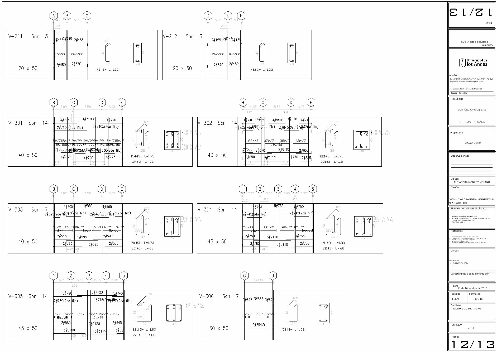
Plano:
Observaciones:
Contiene:
Diseño:
Escala:
Fecha:
1:300
Formato:
ISO B3
Ingenieria Civil - Diseño Estructural
Bogotá - Colombia
Dibujo:
Contiene:
Plano:
Materiales:
Sistema de resistencia sísmica:
- ZONA DE AMENZAZA SISMICA ALTA
- SISTEMA COMBINADO CON CAPACIDAD ESPECIAL DE
DISIPACIÓN DE ENERGÍA (DES)
- GRUPO DE USO: I
VERSION:
V 1.0
12/1312/13
IVONNE ALEJANDRA MONROY M.
M.P. 15202 BYC
IVONNE ALEJANDRA MONROY M.DISEÑO:
· DESPIECE DE VIGAS·DESPIECE DE VIGAS
Proyecto:
Propietario
EDIFICIO ORQUIDEAS
ALEJANDRA MONROY MOLANO
- CONCRETO DE PLACAS: 28 MPa, 4.000 PSI
- CONCRETO DE COLUMNAS Y MUROS: 28 MPa, 4.000 PSI
- ACERO Ø>#2 f'y=420 MPa, 60000 PSI
- ACERO Ø<#2 f'y=420 MPa
- ANCLAJES ASTM F1554 Gr 36 o 3307 Gr 36, Fy=250 MPa
Cargas
Características de la cimentación
CARGAS VIVAS
- VIVIENDA: 1.80 kN/m²
- CUBIERTA: 5.00 kN/m²
DUITAMA - BOYACA
ORQUIDEAS
11 de Diciembre de 2018
AutoCAD SHX Text
V-211
AutoCAD SHX Text
Son 3
AutoCAD SHX Text
20 x 50
AutoCAD SHX Text
A
AutoCAD SHX Text
B
AutoCAD SHX Text
C
AutoCAD SHX Text
.225
AutoCAD SHX Text
4.025
AutoCAD SHX Text
6.03
AutoCAD SHX Text
.22
AutoCAD SHX Text
2#435
AutoCAD SHX Text
2#745
AutoCAD SHX Text
2#455
AutoCAD SHX Text
2#450
AutoCAD SHX Text
2#570
AutoCAD SHX Text
.12
AutoCAD SHX Text
.125
AutoCAD SHX Text
.42
AutoCAD SHX Text
43#3- L=1.33
AutoCAD SHX Text
.20
AutoCAD SHX Text
.50
AutoCAD SHX Text
17c/22
AutoCAD SHX Text
26c/22
AutoCAD SHX Text
1.85
AutoCAD SHX Text
V-212
AutoCAD SHX Text
Son 3
AutoCAD SHX Text
20 x 50
AutoCAD SHX Text
D
AutoCAD SHX Text
E
AutoCAD SHX Text
F
AutoCAD SHX Text
.22
AutoCAD SHX Text
6.03
AutoCAD SHX Text
3.98
AutoCAD SHX Text
.22
AutoCAD SHX Text
2#455
AutoCAD SHX Text
2#745
AutoCAD SHX Text
2#435
AutoCAD SHX Text
2#670
AutoCAD SHX Text
2#450
AutoCAD SHX Text
.12
AutoCAD SHX Text
.125
AutoCAD SHX Text
.42
AutoCAD SHX Text
42#3- L=1.33
AutoCAD SHX Text
.20
AutoCAD SHX Text
.50
AutoCAD SHX Text
26c/22
AutoCAD SHX Text
16c/22
AutoCAD SHX Text
2.33
AutoCAD SHX Text
V-301
AutoCAD SHX Text
Son 14
AutoCAD SHX Text
40 x 50
AutoCAD SHX Text
B
AutoCAD SHX Text
C
AutoCAD SHX Text
D
AutoCAD SHX Text
E
AutoCAD SHX Text
.23
AutoCAD SHX Text
6.02
AutoCAD SHX Text
8.50
AutoCAD SHX Text
6.03
AutoCAD SHX Text
.23
AutoCAD SHX Text
2#7105(2da fila)
AutoCAD SHX Text
4#775
AutoCAD SHX Text
4#7100
AutoCAD SHX Text
2#7105(2da fila)
AutoCAD SHX Text
4#770
AutoCAD SHX Text
4#780
AutoCAD SHX Text
2#635(2da fila)
AutoCAD SHX Text
4#790
AutoCAD SHX Text
2#630(2da fila)
AutoCAD SHX Text
2#630(2da fila)
AutoCAD SHX Text
4#775
AutoCAD SHX Text
2#630(2da fila)
AutoCAD SHX Text
.32
AutoCAD SHX Text
.125
AutoCAD SHX Text
.42
AutoCAD SHX Text
.125
AutoCAD SHX Text
.125
AutoCAD SHX Text
.43
AutoCAD SHX Text
154#3- L=1.73
AutoCAD SHX Text
154#3- L=.68
AutoCAD SHX Text
.40
AutoCAD SHX Text
.50
AutoCAD SHX Text
6.0 1a fila
AutoCAD SHX Text
5.0 2a fila
AutoCAD SHX Text
6.0 1a fila
AutoCAD SHX Text
5.0 2a fila
AutoCAD SHX Text
15c/7
AutoCAD SHX Text
8c/22
AutoCAD SHX Text
15c/7
AutoCAD SHX Text
9c/22
AutoCAD SHX Text
9c/22
AutoCAD SHX Text
15c/7
AutoCAD SHX Text
12c/22
AutoCAD SHX Text
15c/7
AutoCAD SHX Text
9c/22
AutoCAD SHX Text
9c/22
AutoCAD SHX Text
15c/7
AutoCAD SHX Text
8c/22
AutoCAD SHX Text
15c/7
AutoCAD SHX Text
2.19
AutoCAD SHX Text
.47
AutoCAD SHX Text
1.59
AutoCAD SHX Text
.83
AutoCAD SHX Text
.70
AutoCAD SHX Text
V-302
AutoCAD SHX Text
Son 14
AutoCAD SHX Text
40 x 50
AutoCAD SHX Text
B
AutoCAD SHX Text
C
AutoCAD SHX Text
D
AutoCAD SHX Text
E
AutoCAD SHX Text
.23
AutoCAD SHX Text
6.02
AutoCAD SHX Text
8.50
AutoCAD SHX Text
6.03
AutoCAD SHX Text
.22
AutoCAD SHX Text
4#740
AutoCAD SHX Text
2#735(2da fila)
AutoCAD SHX Text
4#670
AutoCAD SHX Text
3#645(2da fila)
AutoCAD SHX Text
4#550
AutoCAD SHX Text
4#670
AutoCAD SHX Text
3#645(2da fila)
AutoCAD SHX Text
4#740
AutoCAD SHX Text
2#735(2da fila)
AutoCAD SHX Text
2#650
AutoCAD SHX Text
2#535
AutoCAD SHX Text
2#670
AutoCAD SHX Text
2#7100
AutoCAD SHX Text
2#6100
AutoCAD SHX Text
2#770
AutoCAD SHX Text
2#650
AutoCAD SHX Text
2#535
AutoCAD SHX Text
.32
AutoCAD SHX Text
.125
AutoCAD SHX Text
.42
AutoCAD SHX Text
.125
AutoCAD SHX Text
.125
AutoCAD SHX Text
.43
AutoCAD SHX Text
221#3- L=1.73
AutoCAD SHX Text
221#3- L=.68
AutoCAD SHX Text
.40
AutoCAD SHX Text
.50
AutoCAD SHX Text
6.0 1a fila
AutoCAD SHX Text
5.0 2a fila
AutoCAD SHX Text
68c/7
AutoCAD SHX Text
37c/7
AutoCAD SHX Text
10c/22
AutoCAD SHX Text
38c/7
AutoCAD SHX Text
68c/7
AutoCAD SHX Text
3.09
AutoCAD SHX Text
1.37
AutoCAD SHX Text
2.82
AutoCAD SHX Text
2.17
AutoCAD SHX Text
3.12
AutoCAD SHX Text
V-303
AutoCAD SHX Text
Son 7
AutoCAD SHX Text
40 x 50
AutoCAD SHX Text
B
AutoCAD SHX Text
C
AutoCAD SHX Text
D
AutoCAD SHX Text
E
AutoCAD SHX Text
.23
AutoCAD SHX Text
6.02
AutoCAD SHX Text
8.50
AutoCAD SHX Text
6.03
AutoCAD SHX Text
.22
AutoCAD SHX Text
4#695
AutoCAD SHX Text
2#625(2da fila)
AutoCAD SHX Text
2#645(2da fila)
AutoCAD SHX Text
4#550
AutoCAD SHX Text
4#695
AutoCAD SHX Text
2#640(2da fila)
AutoCAD SHX Text
2#625(2da fila)
AutoCAD SHX Text
2#590
AutoCAD SHX Text
2#555
AutoCAD SHX Text
2#595
AutoCAD SHX Text
2#595
AutoCAD SHX Text
2#590
AutoCAD SHX Text
2#555
AutoCAD SHX Text
.32
AutoCAD SHX Text
.125
AutoCAD SHX Text
.42
AutoCAD SHX Text
.125
AutoCAD SHX Text
.125
AutoCAD SHX Text
.43
AutoCAD SHX Text
201#3- L=1.73
AutoCAD SHX Text
201#3- L=.68
AutoCAD SHX Text
.40
AutoCAD SHX Text
.50
AutoCAD SHX Text
6.0 1a fila
AutoCAD SHX Text
5.0 2a fila
AutoCAD SHX Text
15c/7
AutoCAD SHX Text
11c/22
AutoCAD SHX Text
30c/7
AutoCAD SHX Text
39c/7
AutoCAD SHX Text
11c/22
AutoCAD SHX Text
40c/7
AutoCAD SHX Text
30c/7
AutoCAD SHX Text
10c/22
AutoCAD SHX Text
15c/7
AutoCAD SHX Text
2.20
AutoCAD SHX Text
1.25
AutoCAD SHX Text
V-304
AutoCAD SHX Text
Son 14
AutoCAD SHX Text
45 x 50
AutoCAD SHX Text
1
AutoCAD SHX Text
2
AutoCAD SHX Text
3
AutoCAD SHX Text
4
AutoCAD SHX Text
5
AutoCAD SHX Text
.20
AutoCAD SHX Text
5.20
AutoCAD SHX Text
5.50
AutoCAD SHX Text
5.05
AutoCAD SHX Text
5.35
AutoCAD SHX Text
.20
AutoCAD SHX Text
5#795
AutoCAD SHX Text
2#745(2da fila)
AutoCAD SHX Text
5#765
AutoCAD SHX Text
5#790
AutoCAD SHX Text
2#745(2da fila)
AutoCAD SHX Text
2#780
AutoCAD SHX Text
3#750
AutoCAD SHX Text
3#7110
AutoCAD SHX Text
2#6110
AutoCAD SHX Text
3#785
AutoCAD SHX Text
2#755
AutoCAD SHX Text
.37
AutoCAD SHX Text
.125
AutoCAD SHX Text
.42
AutoCAD SHX Text
.125
AutoCAD SHX Text
.125
AutoCAD SHX Text
.43
AutoCAD SHX Text
211#3- L=1.83
AutoCAD SHX Text
211#3- L=.68
AutoCAD SHX Text
.45
AutoCAD SHX Text
.50
AutoCAD SHX Text
6.0 1a fila
AutoCAD SHX Text
5.0 2a fila
AutoCAD SHX Text
15c/22
AutoCAD SHX Text
24c/7
AutoCAD SHX Text
68c/7
AutoCAD SHX Text
62c/7
AutoCAD SHX Text
27c/7
AutoCAD SHX Text
15c/22
AutoCAD SHX Text
.23
AutoCAD SHX Text
1.21
AutoCAD SHX Text
1.37
AutoCAD SHX Text
2.39
AutoCAD SHX Text
.29
AutoCAD SHX Text
V-305
AutoCAD SHX Text
Son 14
AutoCAD SHX Text
45 x 50
AutoCAD SHX Text
1
AutoCAD SHX Text
2
AutoCAD SHX Text
3
AutoCAD SHX Text
4
AutoCAD SHX Text
5
AutoCAD SHX Text
.20
AutoCAD SHX Text
5.20
AutoCAD SHX Text
5.50
AutoCAD SHX Text
5.05
AutoCAD SHX Text
5.35
AutoCAD SHX Text
.20
AutoCAD SHX Text
5#790
AutoCAD SHX Text
2#780(2da fila)
AutoCAD SHX Text
5#7120
AutoCAD SHX Text
1#745(2da fila)
AutoCAD SHX Text
5#740
AutoCAD SHX Text
2#730(2da fila)
AutoCAD SHX Text
3#5100
AutoCAD SHX Text
2#580
AutoCAD SHX Text
2#5120
AutoCAD SHX Text
3#5115
AutoCAD SHX Text
2#645
AutoCAD SHX Text
3#525
AutoCAD SHX Text
.37
AutoCAD SHX Text
.125
AutoCAD SHX Text
.42
AutoCAD SHX Text
.125
AutoCAD SHX Text
.125
AutoCAD SHX Text
.43
AutoCAD SHX Text
221#3- L=1.83
AutoCAD SHX Text
221#3- L=.68
AutoCAD SHX Text
.45
AutoCAD SHX Text
.50
AutoCAD SHX Text
6.0 1a fila
AutoCAD SHX Text
5.0 2a fila
AutoCAD SHX Text
15c/7
AutoCAD SHX Text
12c/22
AutoCAD SHX Text
15c/7
AutoCAD SHX Text
69c/7
AutoCAD SHX Text
15c/7
AutoCAD SHX Text
10c/22
AutoCAD SHX Text
15c/7
AutoCAD SHX Text
70c/7
AutoCAD SHX Text
1.08
AutoCAD SHX Text
2.38
AutoCAD SHX Text
1.92
AutoCAD SHX Text
V-306
AutoCAD SHX Text
Son 7
AutoCAD SHX Text
30 x 50
AutoCAD SHX Text
C
AutoCAD SHX Text
D
AutoCAD SHX Text
.225
AutoCAD SHX Text
8.495
AutoCAD SHX Text
.23
AutoCAD SHX Text
3#625
AutoCAD SHX Text
3#565
AutoCAD SHX Text
3#625
AutoCAD SHX Text
3#694.5
AutoCAD SHX Text
.22
AutoCAD SHX Text
.125
AutoCAD SHX Text
.42
AutoCAD SHX Text
56#3- L=1.53
AutoCAD SHX Text
.30
AutoCAD SHX Text
.50
AutoCAD SHX Text
15c/7
AutoCAD SHX Text
26c/22
AutoCAD SHX Text
15c/7

Plano:
Observaciones:
Contiene:
Diseño:
Escala:
Fecha:
1:300
Formato:
ISO B3
Ingenieria Civil - Diseño Estructural
Bogotá - Colombia
Dibujo:
Contiene:
Plano:
Materiales:
Sistema de resistencia sísmica:
- ZONA DE AMENZAZA SISMICA ALTA
- SISTEMA COMBINADO CON CAPACIDAD ESPECIAL DE
DISIPACIÓN DE ENERGÍA (DES)
- GRUPO DE USO: I
VERSION:
V 1.0
13/1313/13
IVONNE ALEJANDRA MONROY M.
M.P. 15202 BYC
IVONNE ALEJANDRA MONROY M.DISEÑO:
· DESPIECE DE VIGAS·DESPIECE DE VIGAS
Proyecto:
Propietario
EDIFICIO ORQUIDEAS
ALEJANDRA MONROY MOLANO
- CONCRETO DE PLACAS: 28 MPa, 4.000 PSI
- CONCRETO DE COLUMNAS Y MUROS: 28 MPa, 4.000 PSI
- ACERO Ø>#2 f'y=420 MPa, 60000 PSI
- ACERO Ø<#2 f'y=420 MPa
- ANCLAJES ASTM F1554 Gr 36 o 3307 Gr 36, Fy=250 MPa
Cargas
Características de la cimentación
CARGAS VIVAS
- VIVIENDA: 1.80 kN/m²
- CUBIERTA: 5.00 kN/m²
DUITAMA - BOYACA
ORQUIDEAS
11 de Diciembre de 2018
AutoCAD SHX Text
V-307
AutoCAD SHX Text
Son 7
AutoCAD SHX Text
30 x 50
AutoCAD SHX Text
C
AutoCAD SHX Text
3#529.5
AutoCAD SHX Text
3#529.5
AutoCAD SHX Text
.22
AutoCAD SHX Text
.125
AutoCAD SHX Text
.42
AutoCAD SHX Text
8#3- L=1.53
AutoCAD SHX Text
.30
AutoCAD SHX Text
.50
AutoCAD SHX Text
8c/22
AutoCAD SHX Text
V-307A
AutoCAD SHX Text
Son 7
AutoCAD SHX Text
30 x 50
AutoCAD SHX Text
D
AutoCAD SHX Text
3#530
AutoCAD SHX Text
3#530
AutoCAD SHX Text
.22
AutoCAD SHX Text
.125
AutoCAD SHX Text
.42
AutoCAD SHX Text
9#3- L=1.53
AutoCAD SHX Text
.30
AutoCAD SHX Text
.50
AutoCAD SHX Text
9c/22
AutoCAD SHX Text
V-308
AutoCAD SHX Text
Son 14
AutoCAD SHX Text
35 x 50
AutoCAD SHX Text
2
AutoCAD SHX Text
4#539.5
AutoCAD SHX Text
4#539.5
AutoCAD SHX Text
.27
AutoCAD SHX Text
.125
AutoCAD SHX Text
.42
AutoCAD SHX Text
14#3- L=1.63
AutoCAD SHX Text
.35
AutoCAD SHX Text
.50
AutoCAD SHX Text
14c/22
AutoCAD SHX Text
V-309
AutoCAD SHX Text
Son 21
AutoCAD SHX Text
20 x 50
AutoCAD SHX Text
B
AutoCAD SHX Text
C
AutoCAD SHX Text
D
AutoCAD SHX Text
E
AutoCAD SHX Text
.23
AutoCAD SHX Text
6.02
AutoCAD SHX Text
8.50
AutoCAD SHX Text
6.03
AutoCAD SHX Text
.22
AutoCAD SHX Text
2#550
AutoCAD SHX Text
2#760
AutoCAD SHX Text
2#750(2da fila)
AutoCAD SHX Text
2#550
AutoCAD SHX Text
2#760
AutoCAD SHX Text
2#750(2da fila)
AutoCAD SHX Text
2#550
AutoCAD SHX Text
1#590
AutoCAD SHX Text
1#555
AutoCAD SHX Text
1#7100
AutoCAD SHX Text
1#795
AutoCAD SHX Text
1#590
AutoCAD SHX Text
1#555
AutoCAD SHX Text
.12
AutoCAD SHX Text
.125
AutoCAD SHX Text
.42
AutoCAD SHX Text
89#3- L=1.33
AutoCAD SHX Text
.20
AutoCAD SHX Text
.50
AutoCAD SHX Text
6.0 1a fila
AutoCAD SHX Text
5.0 2a fila
AutoCAD SHX Text
26c/22
AutoCAD SHX Text
37c/22
AutoCAD SHX Text
26c/22
AutoCAD SHX Text
3.37
AutoCAD SHX Text
1.25
AutoCAD SHX Text
V-310
AutoCAD SHX Text
Son 7
AutoCAD SHX Text
20 x 50
AutoCAD SHX Text
B
AutoCAD SHX Text
C
AutoCAD SHX Text
.23
AutoCAD SHX Text
6.02
AutoCAD SHX Text
.25
AutoCAD SHX Text
2#569
AutoCAD SHX Text
2#771
AutoCAD SHX Text
.12
AutoCAD SHX Text
.125
AutoCAD SHX Text
.42
AutoCAD SHX Text
26#3- L=1.33
AutoCAD SHX Text
.20
AutoCAD SHX Text
.50
AutoCAD SHX Text
26c/22
AutoCAD SHX Text
V-311
AutoCAD SHX Text
Son 7
AutoCAD SHX Text
20 x 50
AutoCAD SHX Text
D
AutoCAD SHX Text
E
AutoCAD SHX Text
.20
AutoCAD SHX Text
6.03
AutoCAD SHX Text
.22
AutoCAD SHX Text
2#568.5
AutoCAD SHX Text
2#770.5
AutoCAD SHX Text
.12
AutoCAD SHX Text
.125
AutoCAD SHX Text
.42
AutoCAD SHX Text
25#3- L=1.33
AutoCAD SHX Text
.20
AutoCAD SHX Text
.50
AutoCAD SHX Text
25c/22