RP2N - Hidraulica Olagorta, S. L. · Membrana acero inoxidable 1.4404 (AISI 316 L) RP2E--Aluminio...
8
www.baumer.com RP2N Compact pressure switch 2014-04-15 Design and specifications subject to change without notice Page 1 / 4 Data sheet A32.01 RP2N Compact pressure switch Main Features Applications Excellent repeatability Dead band adjustment for regulation Fix dead band for control and alarm Resistant to accidental overpressure Light weight Pneumatic appliances Power generation safety equipment Water treatment Valve and compressor control Technical Data Pressure range 0 ... 1 bar to 0 ... 100 bar Temperature Process : -40 ... +150°C Ambient : -30 ... +70°C Storage : -40 ... +70°C Repeatability ± 1% F.S. @ constant pressure cycle CE conformity Low Voltage Directive LVD 2006/95/EC Pressure Equipment Directive PED 97/23/EC Protection rating IP 66 (EN 60529) Process Connection Stainless steel 1.4404 (316L) Diaphragm Stainless steel 1.4404 (316L) Scale Internal graduated scale Weight 0.960 kg Body Zamak black painting Housing Plastic PA6, blue Mounting Wall mounting 2 x M5 screws Options Customer specific set point adjustment Code SETP Oxygen application Code 0765 Mounting on 2" pipe Code 0407 Stainless steel tag plate and wire Code 9941 Lead seal of the housing Code 8990 Ground connection Via internal terminal block Electrical connection Via internal terminal block with cable gland for Ø 5.5 to 8.5 mm Electrical function See ordering code details on page 4 Adjustment Internal adjustment possible for set point and dead band
Transcript of RP2N - Hidraulica Olagorta, S. L. · Membrana acero inoxidable 1.4404 (AISI 316 L) RP2E--Aluminio...
www.baumer.com
RP2NCompact pressure switch
2014
-04-
15
D
esig
n an
d sp
ecifi
catio
ns s
ubje
ct to
cha
nge
with
out n
otic
e
Page 1 / 4Data sheet A32.01
RP2NCompact pressure switch
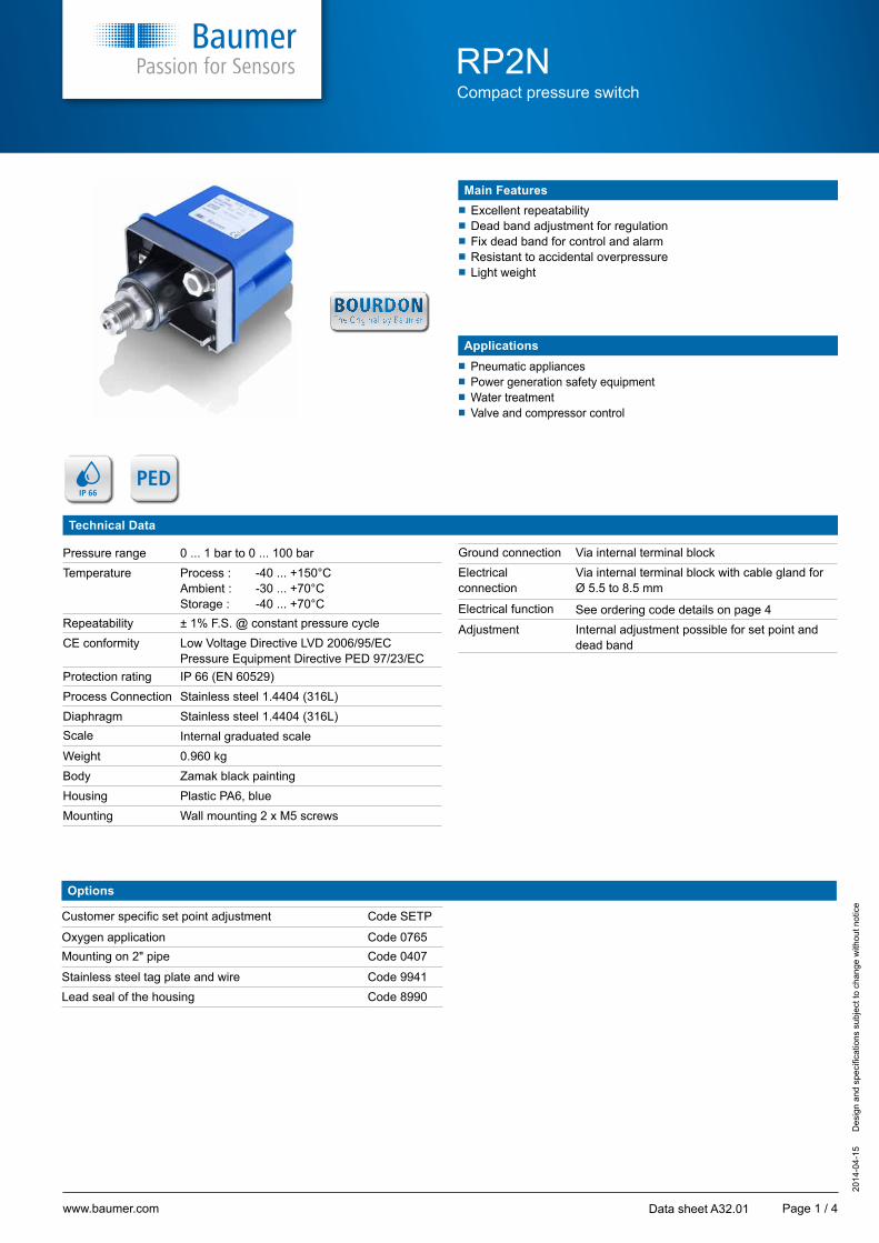
Main Features
Applications
�� Excellent repeatability�� Dead band adjustment for regulation�� Fix dead band for control and alarm�� Resistant to accidental overpressure�� Light weight
�� Pneumatic appliances�� Power generation safety equipment�� Water treatment�� Valve and compressor control
Technical Data
Pressure range 0 ... 1 bar to 0 ... 100 barTemperature Process : -40 ... +150°C
Ambient : -30 ... +70°CStorage : -40 ... +70°C
Repeatability ± 1% F.S. @ constant pressure cycleCE conformity Low Voltage Directive LVD 2006/95/EC
Pressure Equipment Directive PED 97/23/ECProtection rating IP 66 (EN 60529)Process Connection Stainless steel 1.4404 (316L)Diaphragm Stainless steel 1.4404 (316L)Scale Internal graduated scaleWeight 0.960 kgBody Zamak black paintingHousing Plastic PA6, blueMounting Wall mounting 2 x M5 screws
Options
Customer specific set point adjustment Code SETP
Oxygen application Code 0765Mounting on 2" pipe Code 0407
Stainless steel tag plate and wire Code 9941Lead seal of the housing Code 8990
Ground connection Via internal terminal blockElectricalconnection
Via internal terminal block with cable gland forØ 5.5 to 8.5 mm
Electrical function See ordering code details on page 4Adjustment Internal adjustment possible for set point and
dead band
www.baumer.com
P
RP2NCompact pressure switch
2014
-04-
15
D
esig
n an
d sp
ecifi
catio
ns s
ubje
ct to
cha
nge
with
out n
otic
e
Page 2 / 4Data sheet A32.01
Adjustable ranges
Scale P. Maxpermanent
P. Maxaccidental
Code
Micro-switch dead band 1)
Adjustable dead band Fixed dead band
R L M - N - P
bar bar bar
10% 90% 10% 90% 10% 90%
mbar mbar mbar mbar mbar mbar
0 ... 1
10 50
41 N/A N/A 30 60 120 330
0 ... 1.6 42 100 - 200 200 - 550 35 70 150 390
0 ... 2.5 43 125 - 230 250 - 700 40 80 180 480
0 ... 4 44 150 - 290 320 - 900 45 90 210 540
0 ... 6 45 190 - 350 420 - 1200 50 100 240 630
0 ... 10 46 260 - 500 600 - 1800 55 110 300 750
0 ... 4
40 100
51 500 - 1000 1250 - 2000 110 200 600 1320
0 ... 6 52 550 - 1100 1350 - 2200 110 235 750 1620
0 ... 10 53 650 - 1300 1500 - 2600 120 270 840 2010
0 ... 16 54 800 - 1600 1700 - 3100 130 305 960 2370
0 ... 25 55 1000 - 2000 2000 - 3900 140 340 1050 2730
0 ... 40 56 1400 - 2800 2600 - 5200 150 380 1140 3150
0 ... 10
100 200
61 1000 - 2000 3000 - 6000 200 500 1500 3600
0 ... 16 62 1150 - 2300 3500 - 7000 280 700 2100 3960
0 ... 25 63 1350 - 2700 4200 - 8400 360 900 2700 5500
0 ... 40 64 1700 - 3400 5350 - 10700 440 1100 3300 7350
0 ... 60 65 2100 - 4200 6900 - 13800 520 1300 3900 9600
0 ... 100 66 3000 - 6000 10000 - 20000 600 1500 4500 13200
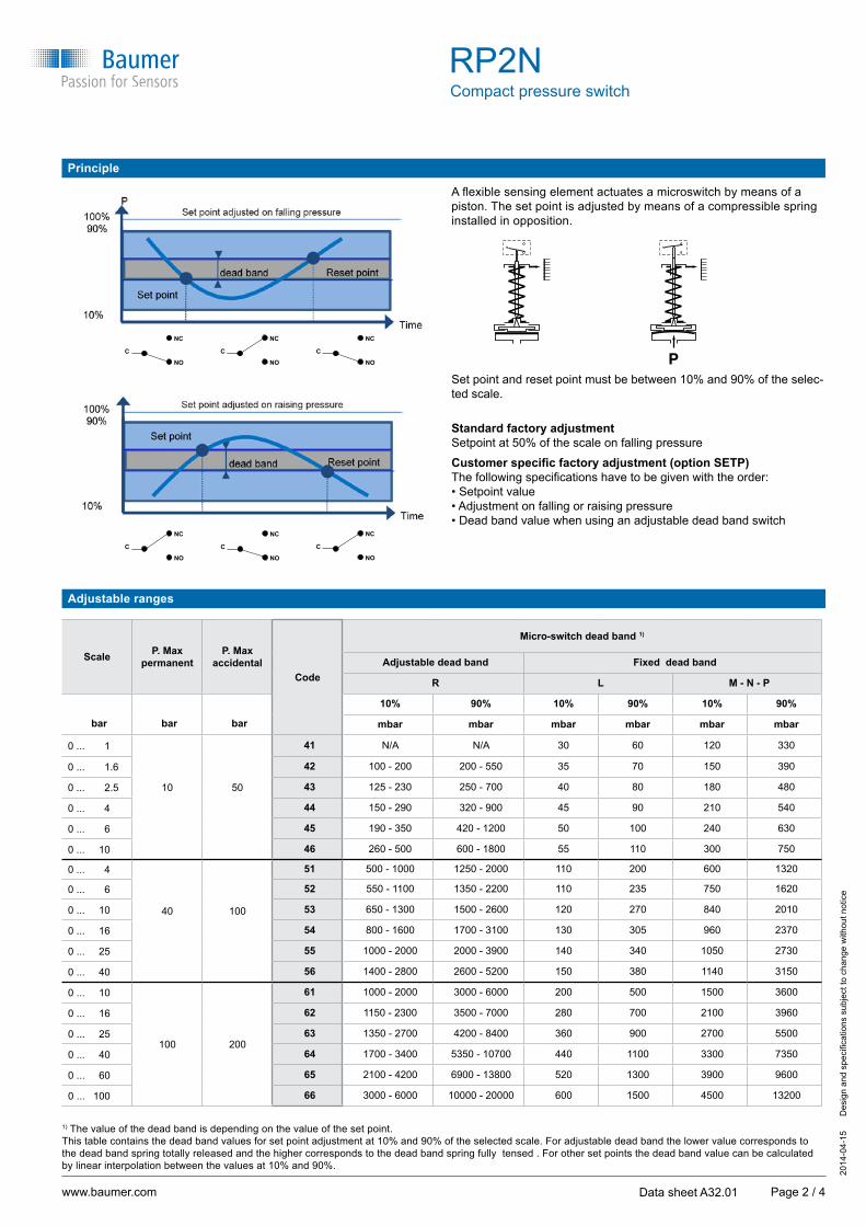
Principle
1) The value of the dead band is depending on the value of the set point.This table contains the dead band values for set point adjustment at 10% and 90% of the selected scale. For adjustable dead band the lower value corresponds to the dead band spring totally released and the higher corresponds to the dead band spring fully tensed . For other set points the dead band value can be calculated by linear interpolation between the values at 10% and 90%.
A flexible sensing element actuates a microswitch by means of a piston. The set point is adjusted by means of a compressible spring installed in opposition.
Set point and reset point must be between 10% and 90% of the selec-ted scale.
Standard factory adjustment Setpoint at 50% of the scale on falling pressure
Customer specific factory adjustment (option SETP)The following specifications have to be given with the order:• Setpoint value• Adjustment on falling or raising pressure• Dead band value when using an adjustable dead band switch
C
NC
NO
C
NC
NO
C
NC
NO
C
NC
NO
C
NC
NO
C
NC
NO
www.baumer.com
68
27 / 2 plats
2 x 5,5
97
73,5
98
33
G1/2 33
68
27 / 2 plats
2 x 5,5
97
73,5
98
33
G1/2 33
COM
NO
NC
RP2NCompact pressure switch
2014
-04-
15
D
esig
n an
d sp
ecifi
catio
ns s
ubje
ct to
cha
nge
with
out n
otic
e
Page 3 / 4Data sheet A32.01
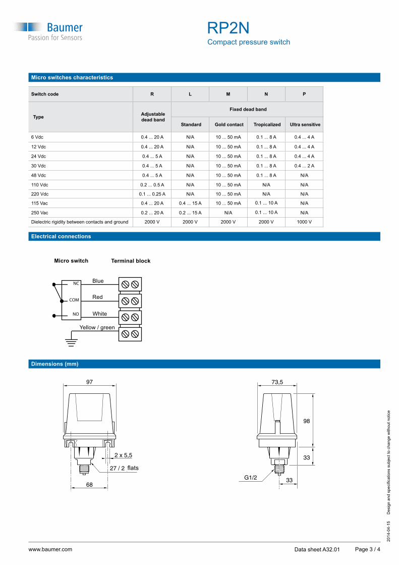
Dimensions (mm)
Electrical connections
Terminal block
Blue
Red
White
Yellow / green
Micro switch
Micro switches characteristics
Switch code R L M N P
Type Adjustabledead band
Fixed dead band
Standard Gold contact Tropicalized Ultra sensitive
6 Vdc 0.4 ... 20 A N/A 10 ... 50 mA 0.1 ... 8 A 0.4 ... 4 A
12 Vdc 0.4 ... 20 A N/A 10 ... 50 mA 0.1 ... 8 A 0.4 ... 4 A
24 Vdc 0.4 ... 5 A N/A 10 ... 50 mA 0.1 ... 8 A 0.4 ... 4 A
30 Vdc 0.4 ... 5 A N/A 10 ... 50 mA 0.1 ... 8 A 0.4 ... 2 A
48 Vdc 0.4 ... 5 A N/A 10 ... 50 mA 0.1 ... 8 A N/A
110 Vdc 0.2 ... 0.5 A N/A 10 ... 50 mA N/A N/A
220 Vdc 0.1 ... 0.25 A N/A 10 ... 50 mA N/A N/A
115 Vac 0.4 ... 20 A 0.4 ... 15 A 10 ... 50 mA 0.1 ... 10 A N/A
250 Vac 0.2 ... 20 A 0.2 ... 15 A N/A 0.1 ... 10 A N/A
Dielectric rigidity between contacts and ground 2000 V 2000 V 2000 V 2000 V 1000 V
flats
www.baumer.com
RP2NCompact pressure switch
2014
-04-
15
D
esig
n an
d sp
ecifi
catio
ns s
ubje
ct to
cha
nge
with
out n
otic
e
Page 4 / 4Data sheet A32.01
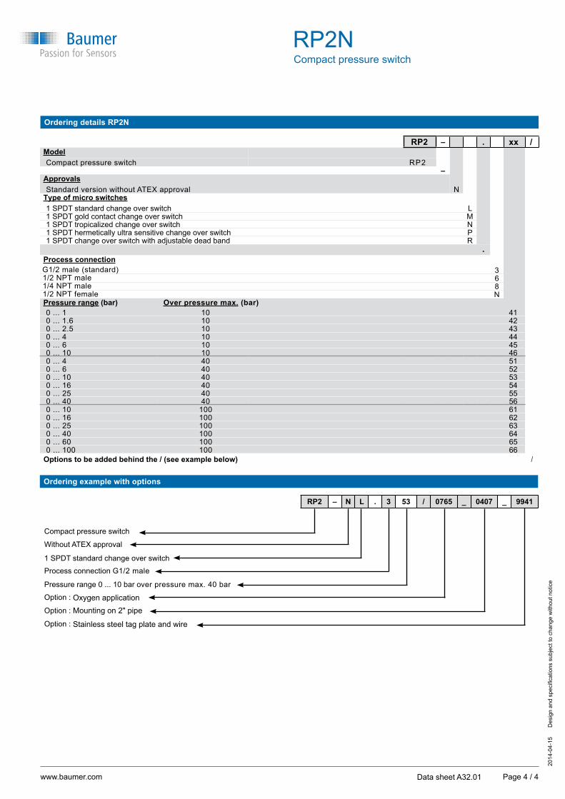
Ordering details RP2N
RP2 – . xx /ModelCompact pressure switch RP2
–ApprovalsStandard version without ATEX approval N
Type of micro switches1 SPDT standard change over switch L1 SPDT gold contact change over switch M1 SPDT tropicalized change over switch N1 SPDT hermetically ultra sensitive change over switch P1 SPDT change over switch with adjustable dead band R
.Process connection
G1/2 male (standard) 31/2 NPT male 61/4 NPT male 81/2 NPT female NPressure range (bar) Over pressure max. (bar)0 ... 1 10 410 ... 1.6 10 420 ... 2.5 10 430 ... 4 10 440 ... 6 10 450 ... 10 10 460 ... 4 40 510 ... 6 40 520 ... 10 40 530 ... 16 40 540 ... 25 40 550 ... 40 40 560 ... 10 100 610 ... 16 100 620 ... 25 100 630 ... 40 100 640 ... 60 100 650 ... 100 100 66
Options to be added behind the / (see example below) /
Ordering example with options
Compact pressure switch
Without ATEX approval
1 SPDT standard change over switch
Process connection G1/2 male
Pressure range 0 ... 10 bar over pressure max. 40 bar
Option : Oxygen applicationOption : Mounting on 2" pipe
Option : Stainless steel tag plate and wire
RP2 – N L . 3 53 / 0765 _ 0407 _ 9941
Placa interna graduada
G 1/2
Membrana de acero inoxidable 1.4404 (AISI 316 L)
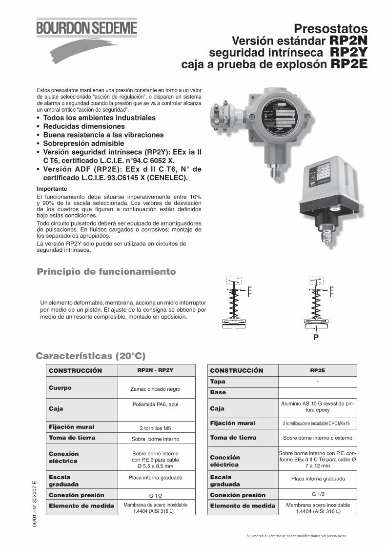
PresostatosVersión estándar RP2N
seguridad intrínseca RP2Ycaja a prueba de explosón RP2E
Estos presostatos mantienen una presión constante en torno a un valor de ajuste seleccionado “acción de regulación”, o disparan un sistema de alarma o seguridad cuando la presión que se va a controlar alcanza un umbral crítico “acción de seguridad”.
• Todos los ambientes industriales• Reducidas dimensiones• Buena resistencia a las vibraciones• Sobrepresión admisible• Versión seguridad intrínseca (RP2Y): EEx ia II C T6, certificado L.C.I.E. n°94.C 6052 X.• Versión ADF (RP2E): EEx d II C T6, N° de certificado L.C.I.E. 93.C6145 X (CENELEC).
ImportanteEl funcionamiento debe situarse imperativemente entre 10% y 90% de la escala seleccionada. Los valores de desviación de los cuadros que figuran a continuación están definidos bajo estas condiciones.Todo circuito pulsatorio deberá ser equipado de amortiguadores de pulsaciones. En fluidos cargados o corrosivos: montaje de los separadores apropiados.La versión RP2Y sólo puede ser utilizada en circuitos de seguridad intrínseca.
06/0
1 -
N°
3020
07 E
CONSTRUCCIÓN
Cuerpo
Caja
Fijación mural
Toma de tierra
Conexióneléctrica
Escalagraduada
Conexión presión
Elemento de medida
RP2N - RP2Y
Zamac cincado negro
Poliamida PA6, azul
2 tornillos M5
Sobre borne interno
Sobre borne internocon P.E.9 para cable
Ø 5,5 a 8,5 mm
CONSTRUCCIÓN
Tapa
Base
Caja
Fijación mural
Toma de tierra
Conexióneléctrica
Escalagraduada
Conexión presión
Elemento de medida
Placa interna graduada
G 1/2
Membrana acero inoxidable 1.4404 (AISI 316 L)
RP2E
-
-
Aluminio AS 10 G revestido pin-tura epoxy
2 tornillos acero inoxidable CHC M6x16
Sobre borne interno o externo
Sobre borne interno con P.E. con-forme EEx d II C T6 para cable Ø
7 a 12 mm
Características (20°C)
Un elemento deformable, membrana, acciona un micro interruptor por medio de un pistón. El ajuste de la consigna se obtiene por medio de un resorte compresible, montado en oposición.
P
Principio de funcionamiento
Se reserva el derecho de hacer modificationes sin previo aviso
Características (20°C)
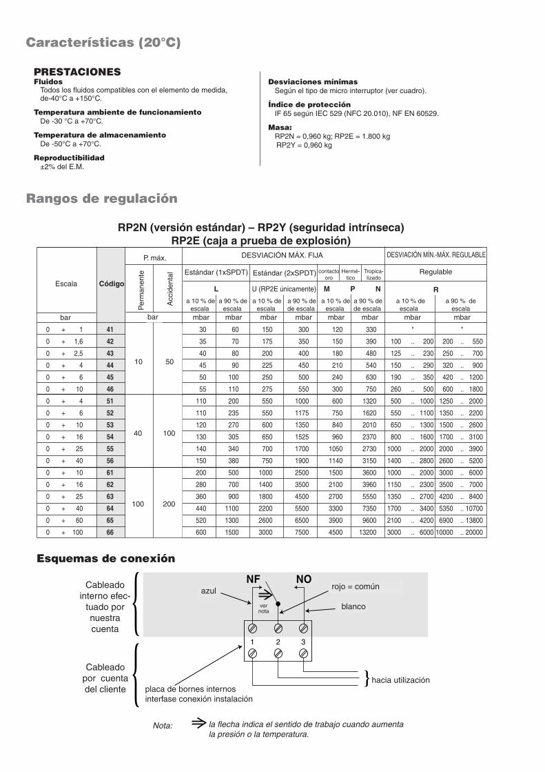
Rangos de regulación
Desviaciones mínimas Según el tipo de micro interruptor (ver cuadro).
Índice de protección IF 65 según IEC 529 (NFC 20.010), NF EN 60529.
Masa: RP2N = 0,960 kg; RP2E = 1.800 kg RP2Y = 0,960 kg
RP2N (versión estándar) – RP2Y (seguridad intrínseca) RP2E (caja a prueba de explosión)
PRESTACIONESFluidos Todos los fluidos compatibles con el elemento de medida, de-40°C a +150°C.
Temperatura ambiente de funcionamiento De -30 °C a +70°C.
Temperatura de almacenamiento De -50°C a +70°C.
Reproductibilidad ±2% del E.M.
Esquemas de conexión
1 2 3
voirnota
rouge = commun
blanc
bleuCâblageinterneeffectuépar nossoins
Câblagepar vossoins bornier interne
interface raccordement installation
vers utilisation
Nota : la flêche indique le sens de travail à la montée de pression ou de température
NF NOCableado interno efec-
tuado por nuestra cuenta
Cableado por cuentadel cliente placa de bornes internos
interfase conexión instalación
la flecha indica el sentido de trabajo cuando aumentala presión o la temperatura.
Nota:
hacia utilización
rojo = común
blancover nota
Escala Código
P. máx. DESVIACIÓN MÍN.-MÁX. REGULABLEDESVIACIÓN MÁX. FIJA
Estándar (1xSPDT) Estándar (2xSPDT) Regulable
L U (RP2E únicamente) R
Per
man
ente
Acc
iden
tal
a 10 % de escala
a 90 % de escala
a 10 % de escala
a 90 % de de escala
a 10 % de escala
a 90 % de de escala
a 10 % de escala
a 90 % de escala
bar mbar mbar mbar mbar mbar mbar mbar mbar
bar
10 50
40 100
100 200
contactooro
Hermé-tico
Tropica-lizado
M P N
0 + 1 41 30 60 150 300 120 330 * *
0 + 1,6 42 35 70 175 350 150 390 100 .. 200 200 .. 550
0 + 2,5 43 40 80 200 400 180 480 125 .. 230 250 .. 700
0 + 4 44 45 90 225 450 210 540 150 .. 290 320 .. 900
0 + 6 45 50 100 250 500 240 630 190 .. 350 420 .. 1200
0 + 10 46 55 110 275 550 300 750 260 .. 500 600 .. 1800
0 + 4 51 110 200 550 1000 600 1320 500 .. 1000 1250 .. 2000
0 + 6 52 110 235 550 1175 750 1620 550 .. 1100 1350 .. 2200
0 + 10 53 120 270 600 1350 840 2010 650 .. 1300 1500 .. 2600
0 + 16 54 130 305 650 1525 960 2370 800 .. 1600 1700 .. 3100
0 + 25 55 140 340 700 1700 1050 2730 1000 .. 2000 2000 .. 3900
0 + 40 56 150 380 750 1900 1140 3150 1400 .. 2800 2600 .. 5200
0 + 10 61 200 500 1000 2500 1500 3600 1000 .. 2000 3000 .. 6000
0 + 16 62 280 700 1400 3500 2100 3960 1150 .. 2300 3500 .. 7000
0 + 25 63 360 900 1800 4500 2700 5550 1350 .. 2700 4200 .. 8400
0 + 40 64 440 1100 2200 5500 3300 7350 1700 .. 3400 5350 .. 10700
0 + 60 65 520 1300 2600 6500 3900 9600 2100 .. 4200 6900 .. 13800
0 + 100 66 600 1500 3000 7500 4500 13200 3000 .. 6000 10000 .. 20000
azul
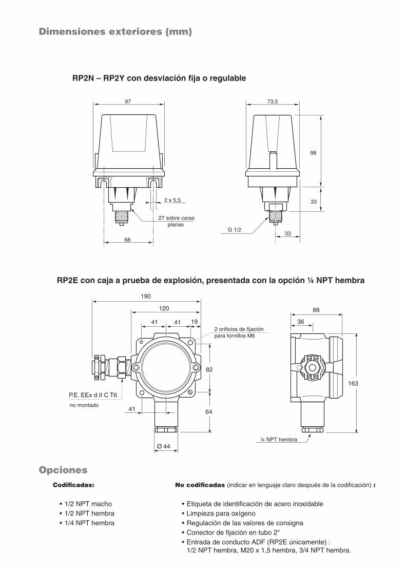
Dimensiones exteriores (mm)
Opciones
RP2N – RP2Y con desviación fija o regulable
RP2E con caja a prueba de explosión, presentada con la opción 1⁄4 NPT hembra
68
27 / 2 plats
2 x 5,5
97
73,5
98
33
68
27 / 2 plats
2 x 5,5
97
73,5
98
33
97
68
2 x 5,5
27 sobre caras planas
73,5
33
33
98
G 1/2
Codificadas: • 1/2 NPT macho • 1/2 NPT hembra • 1/4 NPT hembra
No codificadas (indicar en lenguaje claro después de la codificación) : • Etiqueta de identificación de acero inoxidable • Limpieza para oxígeno • Regulación de las valores de consigna • Conector de fijación en tubo 2" • Entrada de conducto ADF (RP2E únicamente) : 1/2 NPT hembra, M20 x 1,5 hembra, 3/4 NPT hembra.
2 orificios de fijación para tornillos M6
1⁄4 NPT hembra
no montado
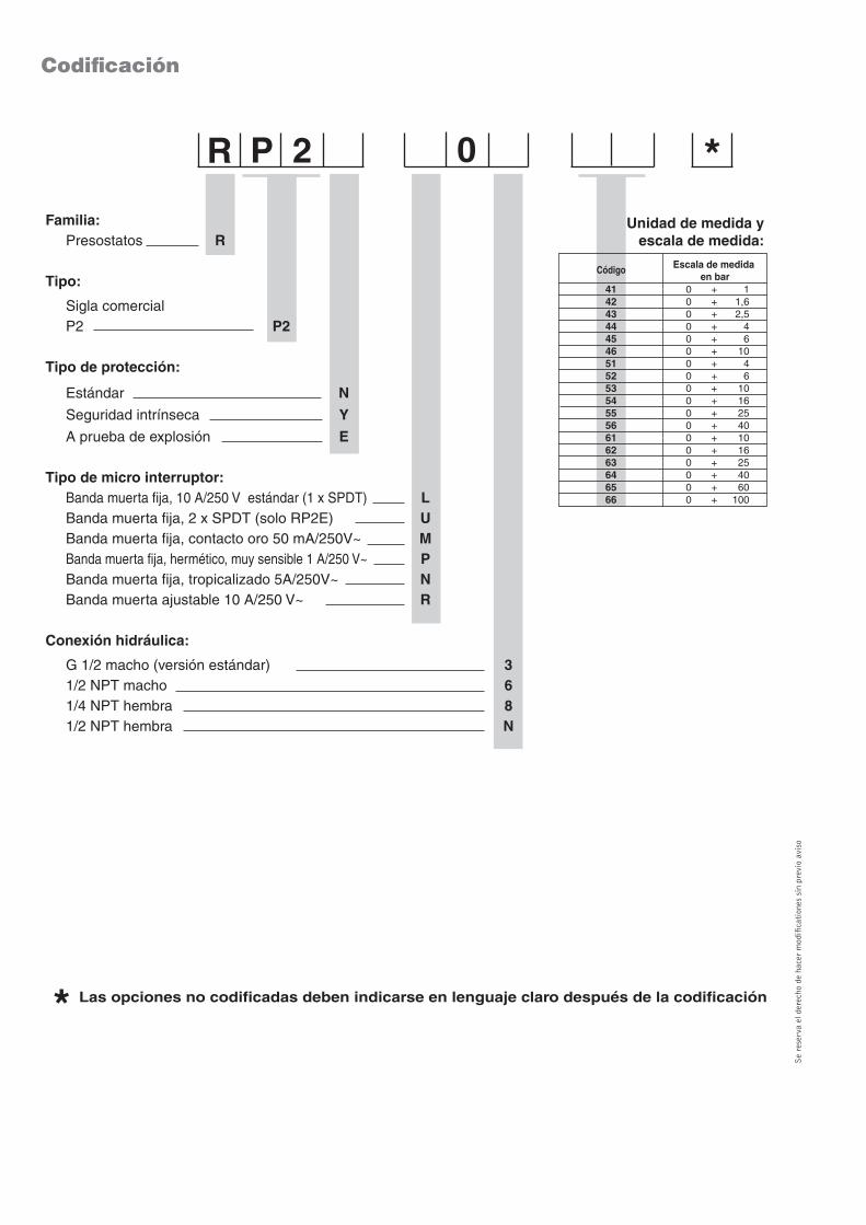
Codificación
41 0 + 1 42 0 + 1,6 43 0 + 2,5 44 0 + 4 45 0 + 6 46 0 + 10 51 0 + 4 52 0 + 6 53 0 + 10 54 0 + 16 55 0 + 25 56 0 + 40 61 0 + 10 62 0 + 16 63 0 + 25 64 0 + 40 65 0 + 60 66 0 + 100
Código Escala de medida en bar
0
Unidad de medida y escala de medida:
Las opciones no codificadas deben indicarse en lenguaje claro después de la codificación*
*
Se
rese
rva
el d
erec
ho d
e ha
cer
mod
ifica
tion
es s
in p
revi
o av
iso
Familia: Presostatos R
Tipo:
Sigla comercial P2 P2
Tipo de protección:
Estándar N
Seguridad intrínseca Y
A prueba de explosión E
Tipo de micro interruptor: Banda muerta fija, 10 A/250 V estándar (1 x SPDT) L Banda muerta fija, 2 x SPDT (solo RP2E) U Banda muerta fija, contacto oro 50 mA/250V~ M Banda muerta fija, hermético, muy sensible 1 A/250 V~ P Banda muerta fija, tropicalizado 5A/250V~ N Banda muerta ajustable 10 A/250 V~ R
Conexión hidráulica:
G 1/2 macho (versión estándar) 3 1/2 NPT macho 6 1/4 NPT hembra 8 1/2 NPT hembra N
R 2P
Josep Sierra
Horizontal