Three-dimensional Printing of Complex Graphite Structures
19
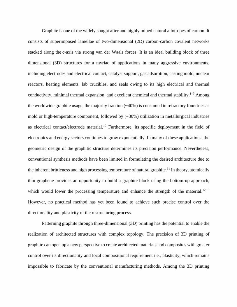
Three-dimensional Printing of Complex Graphite Structures Seyed Mohammad Sajadi 1 *, Shayan Enayat 2 , Lívia Vásárhelyi 3 , Alessandro Alabastri 4 , Minghe Lou 5 , Lucas M. Sassi 1 , Alex Kutana 1 , Sanjit Bhowmick 6 , Christian Durante 1 , Ákos Kukovecz 3 , Anand B. Puthirath 1 , Zoltán Kónya 3 , Robert Vajtai 1 , Peter Boul 7 , Chandra Shekhar Tiwary 8 *, Muhammad M. Rahman 1 *, Pulickel M. Ajayan 1 * 1 Department of Materials Science and NanoEngineering, Rice University, Texas, USA 2 Department of Chemical and Biomolecular Engineering, Rice University, Texas, USA 3 University of Szeged, Interdisciplinary Excellence Centre, Department of Applied and Environmental Chemistry, Szeged, Hungary 4 Department of Electrical and Computer Engineering, Rice University, Texas, USA 5 Department of Chemistry, Rice University, Texas, USA 6 Bruker Nano Surfaces, Minneapolis, Minnesota, USA 7 Aramco Americas, Texas, USA 8 Metallurgical and Materials Engineering, Indian Institute of Technology Kharagpur, India *Corresponds to: [email protected]; [email protected]; [email protected]; [email protected] Graphite, with many industrial applications, is one of the widely sought-after allotropes of carbon. The sp 2 hybridized and thermodynamically stable form of carbon forms a layered structure with strong in-plane carbon bonds and weak inter-layer van der Waals bonding. Graphite is also a high-temperature ceramic, and shaping them into complex geometries is challenging, given its limited sintering behavior even at high temperatures. Although the geometric design of the graphite structure in many of the applications could dictate its precision performance, conventional synthesis methods for formulating complex geometric graphite shapes are limited due to the intrinsic brittleness and difficulties of high- temperature processing. Here, we report the development of colloidal graphite ink from commercial graphite powders with reproducible rheological behavior that allows the fabrication of any complex architectures with tunable geometry and directionality via 3D printing at room temperature. The method is enabled via using small amounts of clay, another layered material, as an additive, allowing the proper design of the graphene ink and subsequent binding of graphite platelets during printing. Sheared layers of clay are easily able to flow, adapt, and interface with graphite layers forming strong binding between the layers and between particles that make the larger structures. The direct ink printing of complex 3D architectures of graphite without further heat treatments could lead to easy shape engineering and related applications of graphite at various length scales, including complex graphite molds or crucibles. The 3D printed complex graphitic structures exhibit excellent thermal, electrical, and mechanical properties, and the clay additive does not seem to alter these properties due to the excellent inter-layer dispersion and mixing within the graphite material. Keywords: Graphite, Complex Geometry, 3D Printing, Conductive ink, Direct Ink Writing
Transcript of Three-dimensional Printing of Complex Graphite Structures
Three-dimensional Printing of Complex Graphite Structures
Seyed Mohammad Sajadi1*, Shayan Enayat2, Lívia Vásárhelyi3, Alessandro Alabastri4, Minghe
Lou5, Lucas M. Sassi1, Alex Kutana1, Sanjit Bhowmick6, Christian Durante1, Ákos Kukovecz3,
Anand B. Puthirath1, Zoltán Kónya3, Robert Vajtai1, Peter Boul7, Chandra Shekhar Tiwary8*,
Muhammad M. Rahman1*, Pulickel M. Ajayan1*
1Department of Materials Science and NanoEngineering, Rice University, Texas, USA 2Department of Chemical and Biomolecular Engineering, Rice University, Texas, USA 3University of Szeged, Interdisciplinary Excellence Centre, Department of Applied and
Environmental Chemistry, Szeged, Hungary 4Department of Electrical and Computer Engineering, Rice University, Texas, USA 5Department of Chemistry, Rice University, Texas, USA 6Bruker Nano Surfaces, Minneapolis, Minnesota, USA 7Aramco Americas, Texas, USA 8Metallurgical and Materials Engineering, Indian Institute of Technology Kharagpur, India
*Corresponds to: [email protected]; [email protected]; [email protected];
Graphite, with many industrial applications, is one of the widely sought-after allotropes of
carbon. The sp2 hybridized and thermodynamically stable form of carbon forms a layered
structure with strong in-plane carbon bonds and weak inter-layer van der Waals bonding.
Graphite is also a high-temperature ceramic, and shaping them into complex geometries
is challenging, given its limited sintering behavior even at high temperatures. Although the
geometric design of the graphite structure in many of the applications could dictate its
precision performance, conventional synthesis methods for formulating complex geometric
graphite shapes are limited due to the intrinsic brittleness and difficulties of high-
temperature processing. Here, we report the development of colloidal graphite ink from
commercial graphite powders with reproducible rheological behavior that allows the
fabrication of any complex architectures with tunable geometry and directionality via
3D printing at room temperature. The method is enabled via using small amounts of clay,
another layered material, as an additive, allowing the proper design of the graphene ink and
subsequent binding of graphite platelets during printing. Sheared layers of clay are easily
able to flow, adapt, and interface with graphite layers forming strong binding between the
layers and between particles that make the larger structures. The direct ink printing of
complex 3D architectures of graphite without further heat treatments could lead to easy
shape engineering and related applications of graphite at various length scales, including
complex graphite molds or crucibles. The 3D printed complex graphitic structures exhibit
excellent thermal, electrical, and mechanical properties, and the clay additive does not seem
to alter these properties due to the excellent inter-layer dispersion and mixing within the
graphite material.
Keywords: Graphite, Complex Geometry, 3D Printing, Conductive ink, Direct Ink Writing
Graphite is one of the widely sought after and highly mined natural allotropes of carbon. It
consists of superimposed lamellae of two-dimensional (2D) carbon-carbon covalent networks
stacked along the c-axis via strong van der Waals forces. It is an ideal building block of three
dimensional (3D) structures for a myriad of applications in many aggressive environments,
including electrodes and electrical contact, catalyst support, gas adsorption, casting mold, nuclear
reactors, heating elements, lab crucibles, and seals owing to its high electrical and thermal
conductivity, minimal thermal expansion, and excellent chemical and thermal stability.1–9 Among
the worldwide graphite usage, the majority fraction (~40%) is consumed in refractory foundries as
mold or high-temperature component, followed by (~30%) utilization in metallurgical industries
as electrical contact/electrode material.10 Furthermore, its specific deployment in the field of
electronics and energy sectors continues to grow exponentially. In many of these applications, the
geometric design of the graphitic structure determines its precision performance. Nevertheless,
conventional synthesis methods have been limited in formulating the desired architecture due to
the inherent brittleness and high processing temperature of natural graphite.11 In theory, atomically
thin graphene provides an opportunity to build a graphite block using the bottom-up approach,
which would lower the processing temperature and enhance the strength of the material.12,13
However, no practical method has yet been found to achieve such precise control over the
directionality and plasticity of the restructuring process.
Patterning graphite through three-dimensional (3D) printing has the potential to enable the
realization of architected structures with complex topology. The precision of 3D printing of
graphite can open up a new perspective to create architected materials and composites with greater
control over its directionality and local compositional requirement i.e., plasticity, which remains
impossible to fabricate by the conventional manufacturing methods. Among the 3D printing
methods, direct ink writing (DIW), an extrusion-based process, offers rapid fabrication of complex
shapes by deposition of colloidal inks in a layer-by-layer fashion. This technique allows excellent
compatibility with a wide array of materials, including polymers, ceramics, cement, and
composites, to develop 3D structures with outstanding properties and multifunctionality.14,15
However, the design of a colloidal graphite ink with critical reproducible rheology still remains a
challenge. The graphite ink must exhibit shear-thinning behavior with desired apparent viscosity,
which facilitates the extrusion of the ink through the nozzle without high printing pressure.
Besides, the printing ink must be integrated with appropriate viscoelastic properties such as high
storage modulus and yield strength to maintain its filamentary shape after extrusion from the
nozzle. As such, the controlled assembly of graphite into tailored 3D architectures via DIW has
not been reported.
Herein for the first time, we report the development of colloidal graphite ink that allows
fabrication of 3D complex architectures with tunable geometry and directionality in ambient
conditions. The graphite ink has successfully addressed the essential rheological characteristics
such as shear thinning and rapid gel strength for DIW of architected structure. The shear-induced
alignment of the graphite sheet during extrusion of the ink was observed along the printing
direction through a Scanning Electron Microscope (SEM), and a simulation of the flow of ink
through the nozzle was implemented. Structural characterization of the printed graphite
architecture was conducted using X-ray diffraction (XRD), Raman spectroscopy, and X-ray
photoelectron spectroscopy (XPS). High-resolution spatial and temporal mapping of temperature
variations during irradiation, four-point probe current-voltage (IV) measurement, and uniaxial
compression tests were performed for thermal, electrical, and mechanical characterization of the
3D printed structure, respectively. We also demonstrate the potential application of the printed
structures in complex metal mold casting, heating element, and electrical circuit/electrode.
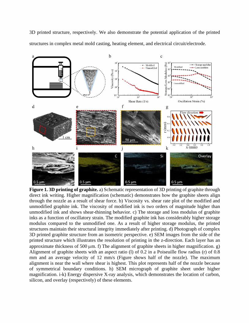
Figure 1. 3D printing of graphite. a) Schematic representation of 3D printing of graphite through
direct ink writing. Higher magnification (schematic) demonstrates how the graphite sheets align
through the nozzle as a result of shear force. b) Viscosity vs. shear rate plot of the modified and
unmodified graphite ink. The viscosity of modified ink is two orders of magnitude higher than
unmodified ink and shows shear-thinning behavior. c) The storage and loss modulus of graphite
inks as a function of oscillatory strain. The modified graphite ink has considerably higher storage
modulus compared to the unmodified one. As a result of higher storage modulus, the printed
structures maintain their structural integrity immediately after printing. d) Photograph of complex
3D printed graphite structure from an isometric perspective. e) SEM images from the side of the
printed structure which illustrates the resolution of printing in the z-direction. Each layer has an
approximate thickness of 500 m. f) The alignment of graphite sheets in higher magnification. g)
Alignment of graphite sheets with an aspect ratio (l) of 0.2 in a Poiseuille flow radius (r) of 0.8
mm and an average velocity of 12 mm/s (Figure shows half of the nozzle). The maximum
alignment is near the wall where shear is highest. This plot represents half of the nozzle because
of symmetrical boundary conditions. h) SEM micrograph of graphite sheet under higher
magnification. i-k) Energy dispersive X-ray analysis, which demonstrates the location of carbon,
silicon, and overlay (respectively) of these elements.
The key factor in the fabrication of complex graphite architecture is the design of
viscoelastic ink that exhibits essential rheological characteristics conducive to DIW. Figure 1a
demonstrates the schematic of 3D printing of graphite through DIW method, the nozzle magnified
to illustrate the particles’ alignment through the tapered tip due to the shear force acting on the
graphite flakes. To achieve high-resolution 3D printing, the ink should uniformly extrude through
the nozzle without discontinuity and particle jamming during the printing process. We observed
two major issues in printing the unmodified graphite slurry - particle jamming in nozzle and
separation of graphite and water under pressure. In order to overcome these issues, nano-clay was
used as a rheology modifier (ink preparation method in the Supplementary Information) rendering
required viscoelastic properties to the ink. Figure 1b-c illustrates the effect on the rheological
properties of graphite slurry due to the addition of nano-clay. The unmodified and modified
graphite slurry showed a viscosity of 0.15 Pa-s and 2.18 Pa-s at the shear rate of 100 s-1,
respectively. At a low shear rate (~1s-1), the unmodified graphite ink exhibits a viscosity of ~9 Pa-
s while the modified graphite ink shows ~345 Pa-s, which is 38 times higher than the unmodified
one. Additionally, to facilitate the printing process, graphite ink must exhibit significantly large
storage modulus to retain the filamentary shape after extrusion from the nozzle. Figure 1c shows
the oscillatory measurement at different strains for modified and unmodified graphite inks. The
modified graphite ink exhibits significantly higher storage modulus (G′) compared to the
unmodified graphite ink. The incorporation of nano-clay increases the storage modulus of graphite
ink by more than 7 times. The modified graphite ink shows the storage modulus of around 90 kPa
at very low strain (0.1%), while the unmodified ink displays a storage modulus of 12 kPa. Another
key figure of merit, the comparison between viscous and elastic material action, is the relative
dissipation – the ratio of G''/ G', related by phase angle, also known as loss tangent (tan ). For the
modified graphite ink, the loss tangent value is less than unity at low oscillation strain, indicating
more solid like (elastic) response of the ink and thus facilitates the filamentary shape retention on
exiting the printing nozzle. Figure 1b-c confirmed that the modified graphite ink exhibits
rheological properties suitable for DIW. Figure 1d exhibits the high-resolution 3D printed complex
graphite structure. This structure was printed using a 1.6 mm tapered nozzle, with the 2.5 cm
length, 2.5 cm width, and 2 cm height (approximately 40 layers). The SEM micrograph (Figure
1e) illustrates the resolution of printing in the z-direction. As a result of shear force in the tapered
nozzle, the graphite sheets align after extrusion from the nozzle, Figure 1f shows aligned graphite
sheets in higher magnification. Further examination of graphite particle motion inside the ink is
determined by simulation and analysis of ink flow in the tapered tip. The motion of the liquid is
assumed to be a steady laminar flow, and graphite sheets are represented as rigid oblate particles
with an aspect ratio l<1 (detailed information about liquid motion simulation is available in the
method section, Supplementary Information). The motion slows down near the turning points,
producing the alignment effect. In the case of oblate particles (l<1), the orbits become sharper with
decreasing aspect ratio, and the particle spends more time with its smallest dimension in alignment
with the direction of the flow. This alignment effect is illustrated in Figure 1g, showing the solution
of Jeffery's equations for graphite sheets with an aspect ratio, l = 0.2 in a Poiseuille flow with an
average velocity of 12 mm/s in a cylinder with 0.8 mm radius. The Figure shows the evolution of
graphite sheets starting with random initial orientations and moving along the flow (from left to
right) at different radial distances from the center of the cylinder. As shown, the alignment effect
is highest near the wall, where shear is maximum, with particles orienting parallel to the flow
direction (details about the simulation of liquid motion and particle orientation are available in the
method section, and Figure S1 in the Supplementary Information). After printing, the structures
were kept at room temperature until the water evaporates to obtain a robust structure. The nano-
clay acts as a binder to prevent the disintegration of graphite structures as well as a rheological
modifier for direct writing. Figure 1i-k illustrates the energy-dispersive X-ray spectroscopy (EDX)
results, demonstrating the role of nano-clay. The presence of carbon and silicon elements (Figure
1i and j) corresponds to graphite and clay in the printed construct. The overlay of these elements
(Figure 1k) indicates the uniform distribution of nano-clay in the graphite ink, which gets attached
to the graphite layers and binds them together, yielding a self-supporting solid structure.
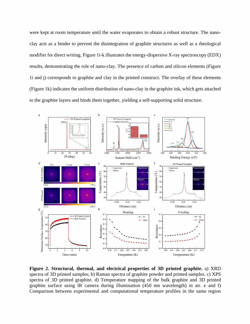
Figure 2. Structural, thermal, and electrical properties of 3D printed graphite. a) XRD
spectra of 3D printed samples; b) Raman spectra of graphite powder and printed samples. c) XPS
spectra of 3D printed graphite. d) Temperature mapping of the bulk graphite and 3D printed
graphite surface using IR camera during illumination (450 nm wavelength) in air. e and f)
Comparison between experimental and computational temperature profiles in the same region
(indicated with a white arrow in the temperature mapping shown in inset) of bulk graphite and 3D
printed graphite, respectively. g) Temporal profile of the maximum surface temperature of bulk
and 3d printed graphite during illumination of laser in the air. h and i) The electrical resistance of
3D printed samples at different temperatures during the heating and cooling process.
Structural characterization was carried out on the printed graphite structure to illustrate the
effect of the printing process. Figure 2a shows the X-ray diffraction (XRD) pattern of 3D printed
graphite structure. We observed two characteristic peaks at 2θ = 26.7° and 2θ = 54.7°, which
represents the Bragg reflections of the (002) and (004) planes, respectively. The absence of
diffraction lines other than the (00l) lines demonstrates the high degree of alignment of the graphite
flakes16,17, as shown in the SEM images in Figures 1e and 1f. Moreover, the fact that the intensity
of the (004) reflection is much lower than that of the (002) reflection implies that there are large
twist angles between the graphite planes.18 Such twisting is likely to occur during the restacking
of the graphite flakes during extrusion through the nozzle (Figure 1g), promoting the formation of
turbostratic carbon (or turbostratic graphite). Turbostratic carbon is a form of graphite in which
the stacking of the graphene layers differs from the thermodynamically favorable AB stacking
found in pure graphite19,20. In addition to the restacking of graphite flakes during the printing
process, the formation of turbostratic graphite could stem from the ball milling process used for
the preparation of the graphite ink. It has been reported in the literature that the ball milling can
induce enough energy to stimulate the formation of the turbostratic structure.19,21
Raman spectroscopy measurement (Figure 2b) shows three primary distinguishable
vibrations for the 3D printed graphite and the pristine graphite powder: (i) The vibration that is
represented by the band at ~1350 cm-1, known as D-band (defects), is related to a disordered
graphitic structure with an A1g-symmetry (ii) The Raman active vibration at ~ 1580 cm-1
corresponds to a highly ordered graphite-like structure related to an E2g-symmetry, known as G-
band (in-plane C-C stretching vibration) and (iii) vibration at around ~2850 cm-1, known as 2D
band, which is a second-order contribution of the D band, involving a two-phonon process.22 As
can be observed from Figure 2b, the two main differences in the Raman spectra are- (1) the change
in the line shape of the 2D band and (2) the ID/IG ratio (intensity of D band to intensity of G band
ratio). The explanation for the first consists mainly in the formation of turbostratic carbon, as
discussed previously. The lack of AB stacking in turbostratic graphite results in electronic
decoupling and a weaker interaction between the layers which, in turn, is evidenced by a single
Lorentzian fit to the 2D band as a spectroscopic signature.20,23,24 Another contribution for the single
Lorentzian fit to the 2D band can arise due to the broadening of the 2D band that occurs because
of the reduction of the graphite crystallite size during the ball milling process.25 The increase in
the ID/IG ratio also traces back to the initial ball milling process and the reduction of the average
crystallite size followed by the introduction of structural defects in the graphite flakes during the
milling process. This results in the increase of the D band whereas the G band is not much affected
by the introduction of defects.22–24
In order to determine the elemental composition of the 3D printed sample, X-ray
photoelectron spectroscopy (XPS) was performed. Figure 2c presents a high-resolution XPS
spectrum of the printed graphite (the survey spectrum shown in Figure S4 in the Supporting
Information). The spectrum of C 1s is deconvoluted in a total of 5 peaks: The peak at 284 eV is
assigned to sp2 C=C bond, the peak at 285.32 eV is assigned to sp3 C−C, and the remaining peaks
are attributed to C−Si bonds at 282.94 eV, C−O groups at 286.38 eV, and C=O groups at 287.69
eV. Except for the C−Si peak, the obtained deconvoluted peaks are very similar to those obtained
for ball-milled graphite powder.26 In this case, the C−Si peak (the peak at ~283 eV) accounts for
the bonds between the graphite flakes and the nano-clay added in the graphite ink, since nano-
clays are mostly silicates.27 The peaks at 286.38 eV and 287.69 eV can be attributed to C-O and
C=O as residual contamination from the air.28 Although a pure graphitic system should mostly
contain sp2 bonds, it was demonstrated that the sp3 peak in graphitic systems arises due to
defects.26,29 In the printed constructs, possible sources of defects that can potentially disturb the
sp2 configuration are the C−Si bonds, oxygen contamination from the air and defects generated in
the graphite flakes due to the milling process, which lead to C−H bond termination, promoting a
transition of the sp2 carbon to the sp3 configuration.26
Graphite is widely used in refractory foundries and heat sink applications; it is of practical
importance to investigate the effect of the printing process on the thermal properties of the 3D
printed structures and compare it with bulk samples. Figure 2d presents the high-resolution spatial
and temporal mapping of temperature variations of bulk graphite, and 3D printed graphite under
illumination. The thermal conductivity of both samples was obtained through indirect
measurement and leveraging from the thermal simulation of the experiment (Figure 2e and 2f, and
details about thermal simulation are available in the method section, Figure S2-S3, and Table S1
in Supplementary Information). To determine the thermal conductivity, the single line temperature
profile was extracted from temperature mapping captured by the IR camera for both samples. Then
the thermal conductivity of printed samples and bulk graphite was found out by fitting the
experimental temperature profile to the simulation in the same region (indicated by a white arrow
in the inset images of Figures 2e and 2f). As shown in Figures 2e and f, the temperature profiles
are in good agreement in experiment and simulation yielding almost equal thermal conductivity
for the 3D printed sample (~9 W/m-K) and bulk graphite (10 W/m-K)30. Thus, the printing process
and ink additives do not affect the heat transfer behavior of the graphite structure. Figure 2g shows
the temporal profile of the maximum temperature of the surface during the illumination of the laser
and the cool-down rate after removing the illumination source. Interestingly, the heat dissipation
rate has been found to be very similar for both samples (Figure 2g). The differences in the
maximum surface temperature of 3D printed and bulk graphite during the illumination period,
though negligible, suggest that the 3D printed sample has slightly more heat resistance, which is
likely due to the addition of nano-clay.31 Clay addition is also expected to impart better thermal
stress distribution in the printed samples. As can be seen from Figure 2d, for the bulk graphite
samples, a higher temperature is observed during illumination along the circumferential edges,
indicating local accumulation of thermal stresses. On the other hand, the temperature profile is
more evenly distributed for the corresponding 3D printed samples, suggesting improved thermal
distribution. The electrical conductivity of the graphite structure is one of the critical elements in
many applications like electrical circuits, heater element, and electrodes. In this study, the
electrical resistance was determined at different temperatures during the heating and cooling of the
3D printed graphite sample (Figures 2h and i, respectively). The average resistivity of the 3D
graphite structure is ≈ 0.18 Ω cm. Although clays are essentially insulating materials and hence,
would act as potential barriers in the electronic conduction path in the printed sample, the small
dimension of clay platelets and therefore, smaller barrier width, might allow the electrons to
quantum mechanically tunnel through them and maintain almost similar conductivity as that of
pure graphite.32
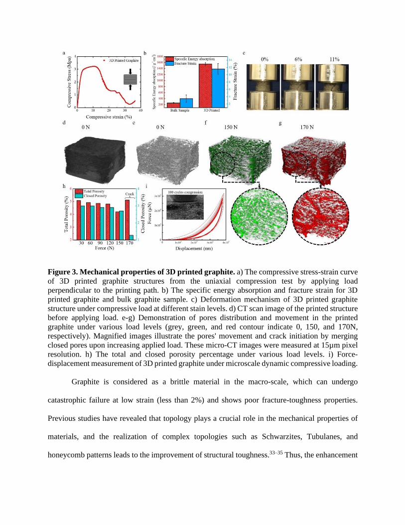
Figure 3. Mechanical properties of 3D printed graphite. a) The compressive stress-strain curve
of 3D printed graphite structures from the uniaxial compression test by applying load
perpendicular to the printing path. b) The specific energy absorption and fracture strain for 3D
printed graphite and bulk graphite sample. c) Deformation mechanism of 3D printed graphite
structure under compressive load at different stain levels. d) CT scan image of the printed structure
before applying load. e-g) Demonstration of pores distribution and movement in the printed
graphite under various load levels (grey, green, and red contour indicate 0, 150, and 170N,
respectively). Magnified images illustrate the pores' movement and crack initiation by merging
closed pores upon increasing applied load. These micro-CT images were measured at 15µm pixel
resolution. h) The total and closed porosity percentage under various load levels. i) Force-
displacement measurement of 3D printed graphite under microscale dynamic compressive loading.
Graphite is considered as a brittle material in the macro-scale, which can undergo
catastrophic failure at low strain (less than 2%) and shows poor fracture-toughness properties.
Previous studies have revealed that topology plays a crucial role in the mechanical properties of
materials, and the realization of complex topologies such as Schwarzites, Tubulanes, and
honeycomb patterns leads to the improvement of structural toughness.33–35 Thus, the enhancement
of mechanical properties of graphite structure is possible by printing complex topologies using
additive manufacturing techniques. Since DIW printing is a layer by layer process, the printed
structure has an anisotropic property, and the mechanical properties depend on the printing path
and direction. Therefore, the uniaxial compression test was carried out on the 3D printed graphite
structure perpendicular and parallel to the printing direction, and the related stress-strain curves
are shown in Figure 3a and Figure S5. As can be seen, the printed graphite structure exhibits ductile
behavior when the load is applied perpendicular to the printing path. Atypical for a brittle material
like graphite, the printed graphite structure first experiences a linear (elastic) region for
compression strain up to 3%, then a plateau (plastic) region beyond 14% strain followed by a
nonlinear (failure) region. However, this was expected from the viscoelastic characterization of
the modified ink (Figure 1c), which exhibited enhanced loss modulus throughout the entire
window of the experimental timescale (strain rate in this case), suggesting enhanced energy
dissipation mechanism in the modified ink than the unmodified one. The graphite sheets after
extrusion from the nozzle facilitate the dislocation and movement of graphite sheets in the plane
and enhance the fracture strain for the compression test carried out perpendicular to the printing
path. The alignment of the printed graphite sheets is further confirmed by the compression test
carried out in the direction of the printing path, which exhibits a progressive crushing
phenomenon- a characteristic of buckling failure (Figure S5, Supplementary Information). In
Figure 3b, the specific energy absorption and fracture strain were compared for printed and bulk
graphite, which was shown to increase by more than 6 and 3 times, respectively. The deformation
mechanism of 3D printed graphite cylinder is shown in a series of snapshots at different strain
rates, which confirms the ductile behavior of the 3D printed graphite structure. Interestingly, the
printed samples do not disintegrate even at 11% strain, while the bulk samples collapse at 2%
compressive strain (Figure S6, Supplementary Information). The crack occurred along the shear
propagation direction, which could be attributed to the elimination of layer boundary and form a
strong interaction between layers in our printing method. To better understand the failure
mechanism of 3D printed graphite structure, the in situ micro-Computed Tomography (CT) scan
images were captured at different compressive loads. The porosity of the 3D printed structure was
obtained through high resolution (800 nm pixel) CT scanning (Figure S7, Supplementary
Information). Figure 3d shows the CT images of 3D printed nonpatterned graphite in the initial
stage, and Figure 3e represents the pores in the same structure. To demonstrate the crack initiation
and propagation phenomena, the distribution and movement of the pores under different
compressive loads are shown in Figure 3e-g. The grey color represents the initial condition of the
structures, and the color shift from green to red indicates the increase in the compressive load.
While applying the compressive load on the graphite sample, we observed the movement of pores;
by increasing the load level, the small pores connected and initiated crack. The fastening of the
pores and consequent crack initiations were evident in the magnified CT images of Figures 3f and
g. The total porosity (summation of closed and open pores) and closed porosity (the pores that do
not have a connection with the outside of the sample) were presented as a function of the applied
force in Figure 3h. By increasing the force, the closed pores percentage decreased since they
densified and connected to form open pores, which have a connection with the outside of the
sample, thus yielding cracks. Before crack initiation, the percentage of total porosity decreased,
and right after crack formation, it increased rapidly.
Figure 3i presents the 100 compressive cycles of force-displacement curves on the printed
graphite sample, which exhibits a somewhat consistent hysteresis during multiple loading and
unloading events. Generally, hysteresis in force-displacement curves suggests that there is energy
dissipation, and the decrease in the force-displacement hysteresis after the first or first few loading-
unloading cycles is indicative of lower fracture energy. However, in our case, the repeatable
hysteresis over multiple loading-unloading cycles suggests that the printed structure has high
fracture energy, and is anti-fatigue at microscale deformations.36
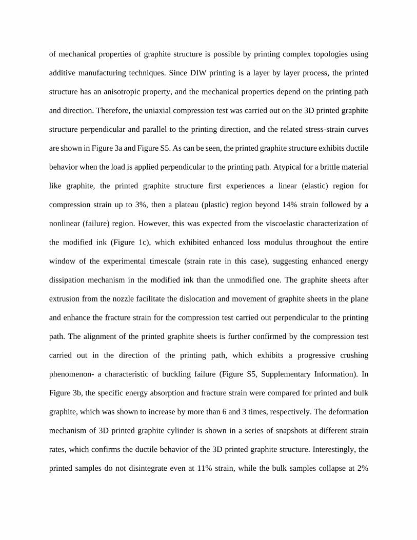
Figure 4. Applications of 3D printed graphite. a) 3D printed complex structures with modified
graphite ink. b) The 3D printed casting mold of graphite ii) Graphite mold filled with copper
powder. iii) the copper piece after sintering in the furnace. c) i) The printed graphite circuit in the
shape of an owl, which has several LED bulbs. ii) the blue LEDs were turned on by applying the
DC voltage, iii) by changing the voltage polarity red LEDs (leads are connected vice versa for blue
and red LEDs) were turned on. d) The printed heater element, ii) the petri dish full of water placed
on top of the heater. iii) By applying an appropriate power, the water temperature reached the
boiling point.
The high plasticity, electrical and thermal conductivity of the 3D printed graphite structures
have been utilized in a series of applications, as shown in Figure 4. Graphite is used as a mold for
metal casting; however, due to the brittle nature of graphite, fabricating a complex-shaped mold
has been a traditionally challenging task. The additive manufacturing technology can significantly
expand the production of complex topology mold, which remains unattainable with the
conventional synthesis method. Figure 4a shows an array of structures, which were 3D printed
using the graphite ink, demonstrating the feasibility of achieving complex shapes. The top two
structures in Figure 4a represent theoretical structures called Schwarzite, which has positive and
negative Gaussian curvatures and could not be built without additive manufacturing technology.34
These structures were printed using 1.64 mm tapered nozzles of different sizes. The height of these
structures ranges from 1cm to 5 cm (20 to 100 layers, respectively). This confirms the high stiffness
of the graphite ink, enabling the printed construct to withstand the load of the above layer(s)
without deformation. Figure 4b demonstrates the 3D printed graphite mold (I), the mold filled with
copper powder (II) and the copper part after sintering in the furnace (III) which has the exact shape
of the mold (more information related to casting metal with different methods and elements are
available Figure S8 in the Supplementary Information which reveals the durability of graphite
mold). Figure 4b shows a printed graphite circuit in the shape of an owl, which has several LED
bulbs connected to it. Figure 4c II and III show the LEDs turn on by applying a 3V DC voltage on
the circuit, and by changing the positive and negative pole, different colors of LEDs were turned
on. Another critical application of graphite is manufacturing 3D elements for heating applications.
Figure 4d (I) shows the printed graphite element connected to a power supply. A petri dish full of
water was placed on top of the graphite heater element (Figure 4c II). Once the appropriate voltage
was applied, the water started boiling (Figure 4d III). In all of these applications, graphite can be
printed in different complex forms, which possess excellent electrical and thermal conductivity
and can be used right after printing without any further processing like sintering.
In summary, we demonstrate the development of a graphite ink with essential rheological
properties conducive to direct ink writing of complex 3D graphite architecture. Electron
microscopy studies revealed shear-induced alignment of graphite sheets, further analyzed, and
confirmed by simulation of the ink flow and mechanical testing as well. Experimental and
computational temporal temperature profiling revealed excellent heat transfer behavior of the 3D
printed sample. The printed graphite structures have superior electrical properties, as shown by the
IV measurements and mechanical properties confirmed by uniaxial compression test, force-
displacement measurement, and CT scan imaging. Finally, the structures were successfully
incorporated in a series of applications, demonstrating the power of the DIW technique in the
design of practical and intricate large-scale multifunctional 3D graphitic architectures.
References
1. Ghosh, S. et al. Dimensional crossover of thermal transport in few-layer graphene. Nat.
Mater. 9, 555–558 (2010).
2. Rudnev, A. V. et al. Stable anchoring chemistry for room temperature charge transport
through graphite-molecule contacts. Sci. Adv. 3, e1602297 (2017).
3. Liu, Y., Zhu, Y. & Cui, Y. Challenges and opportunities towards fast-charging battery
materials. Nat. Energy 4, 540–550 (2019).
4. Prasher, R. Graphene Spreads the Heat. Science (80-. ). 328, 185–186 (2010).
5. Li, S., Cheng, C. & Thomas, A. Carbon-Based Microbial-Fuel-Cell Electrodes: From
Conductive Supports to Active Catalysts. Adv. Mater. 29, 1602547 (2017).
6. Tsen, A. W. et al. Tailoring Electrical Transport Across Grain Boundaries in
Polycrystalline Graphene. Science (80-. ). 336, 1143–1146 (2012).
7. Billaud, J., Bouville, F., Magrini, T., Villevieille, C. & Studart, A. R. Magnetically aligned
graphite electrodes for high-rate performance Li-ion batteries. Nat. Energy 1, 16097
(2016).
8. Jeon, I., Yoon, B., He, M. & Swager, T. M. Hyperstage Graphite: Electrochemical
Synthesis and Spontaneous Reactive Exfoliation. Adv. Mater. 30, 1704538 (2018).
9. Terrones, M. et al. Graphene and graphite nanoribbons: Morphology, properties,
synthesis, defects and applications. Nano Today 5, 351–372 (2010).
10. United States Geological Survey (USGS). Mineral Commodity Summaries 2020. U.S
Departtment OF The Interior, (2020).
11. Liu, D., Gludovatz, B., Barnard, H. S., Kuball, M. & Ritchie, R. O. Damage tolerance of
nuclear graphite at elevated temperatures. Nat. Commun. 8, 15942 (2017).
12. Gong, Y. et al. A bottom-up approach to build 3D architectures from nanosheets for
superior lithium storage. Adv. Funct. Mater. 24, 125–130 (2014).
13. Zhi, L. & Müllen, K. A bottom-up approach from molecular nanographenes to
unconventional carbon materials. J. Mater. Chem. 18, 1472–1484 (2008).
14. Lewis, J. A. Direct ink writing of 3D functional materials. Adv. Funct. Mater. 16, 2193–
2204 (2006).
15. Sajadi, S. M. et al. Direct Ink Writing of Cement Structures Modified with Nanoscale
Additive. Adv. Eng. Mater. 1801380, 1–10 (2019).
16. Endo, M. et al. Structural characterization of carbon nanofibers obtained by hydrocarbon
pyrolysis. Carbon N. Y. 39, 2003–2010 (2001).
17. Hishiyama, Y. & Nakamura, M. X-ray diffraction in oriented carbon films with
turbostratic structure. Carbon N. Y. 33, 1399–1403 (1995).
18. Boi, F. S., Shuai, G., Wen, J. & Wang, S. Unusual Moiré superlattices in exfoliated μm-
thin HOPG lamellae: An angular-diffraction study. Diam. Relat. Mater. 108, 107920
(2020).
19. Li, Z. Q., Lu, C. J., Xia, Z. P., Zhou, Y. & Luo, Z. X-ray diffraction patterns of graphite
and turbostratic carbon. Carbon N. Y. 45, 1686–1695 (2007).
20. Anguita, J. V., Ahmad, M., Haq, S., Allam, J. & Silva, S. R. P. Ultra-broadband light
trapping using nanotextured decoupled graphene multilayers. Sci. Adv. 2, e1501238
(2016).
21. Salver-Disma, F., Tarascon, J.-M., Clinard, C. & Rouzaud, J.-N. Transmission electron
microscopy studies on carbon materials prepared by mechanical milling. Carbon N. Y. 37,
1941–1959 (1999).
22. Pimenta, M. A. et al. Studying disorder in graphite-based systems by Raman
spectroscopy. Phys. Chem. Chem. Phys. 9, 1276–1290 (2007).
23. Radhika, R. et al. Structural transformation and friction behavior in turbostratic graphite
sliding against Si3N4, SiC and Al2O3 balls. Surf. Coatings Technol. 253, 300–306 (2014).
24. Cançado, L. G. et al. Measuring the degree of stacking order in graphite by Raman
spectroscopy. Carbon N. Y. 46, 272–275 (2008).
25. Liu, H. et al. Magnetic plasmon hybridization and optical activity at optical frequencies in
metallic nanostructures. Phys. Rev. B - Condens. Matter Mater. Phys. 76, 1–4 (2007).
26. Estrade-Szwarckopf, H. XPS photoemission in carbonaceous materials: A “defect” peak
beside the graphitic asymmetric peak. Carbon N. Y. 42, 1713–1721 (2004).
27. Contarini, S., Howlett, S. P., Rizzo, C. & De Angelis, B. A. XPS study on the dispersion
of carbon additives in silicon carbide powders. Appl. Surf. Sci. 51, 177–183 (1991).
28. Wollbrink, A. et al. Amorphous, turbostratic and crystalline carbon membranes with
hydrogen selectivity. Carbon N. Y. 106, 93–105 (2016).
29. Castro, K. L. S. et al. Calcium incorporation in graphene oxide particles: A
morphological, chemical, electrical, and thermal study. Thin Solid Films 610, 10–18
(2016).
30. Ho, C. Y., Powell, R. W. & Liley, P. E. Thermal Conductivity of the Element. J. Phys.
Chem. Ref. Data 2, 279–421 (1972).
31. Gabr, M. H. et al. Mechanical and thermal properties of carbon fiber/polypropylene
composite filled with nano-clay. Compos. Part B Eng. 69, 94–100 (2015).
32. Ayatollahi, M. R., Shokrieh, M. M., Shadlou, S., Kefayati, A. R. & Chitsazzadeh, M.
Mechanical and Electrical Properties of Epoxy/ Multi-walled Carbon Nanotube/Nanoclay
Nanocomposites. Iran. Polym. J. c, 835–843 (2011).
33. Compton, B. G. & Lewis, J. A. 3D-printing of lightweight cellular composites. Adv.
Mater. 26, 5930–5935 (2014).
34. Sajadi, S. M. et al. Multiscale Geometric Design Principles Applied to 3D Printed
Schwarzites. Adv. Mater. 30, 1704820 (2018).
35. Sajadi, S. M. et al. 3D Printed Tubulanes as Lightweight Hypervelocity Impact Resistant
Structures. Small 15, 1–9 (2019).
36. Zhao, X. Multi-scale multi-mechanism design of tough hydrogels: building dissipation
into stretchy networks. Soft Matter 10, 672–687 (2014).
Acknowledgment
The authors acknowledged Aramco Research Center for funding this research (Grant number:
1137681). L.M.S. acknowledges CAPES (Coordination for the Improvement of Higher
Education Personnel) under the Brazilian Ministry of Education for the
financial support.
Author contribution
S.M.S, M.M.R., C.S.T., P.M.A conceived and coordinated the research, S.M.S and C.D processed
the sample and performed the mechanical testing. S.B performed Nanomechanical test. L.V, A.K
and R.V conducted CT scanning and reconstructed the data for quantitative analysis. S.M.S, S.E
and L.M.S conducted material characterization. A.A, M.L and M.M.R. did the thermal
conductivity and related analysis, S.M.S and A.B.P performed electrical conductivity testing.
S.M.S, C.S.T and R.V investigated the structure, all author analysed and discussed the results,
S.M.S, L.M.S, P.B, C.T, C.S.T, M.M.R and P.M.A wrote the manuscript.
Additional information
Method
Figures S1-S8
Table S1
Competing financial interests
The authors declare no competing financial interests.


![Concrete 3d printing[1]](https://static.fdocuments.es/doc/165x107/58ef7d0b1a28ab1c0a8b465f/concrete-3d-printing1.jpg)