TO THE POSSIBILITY OF CALCULATIONrepositorio.utn.edu.ec/bitstream/123456789/5847/2/ARTICLE.pdf ·...
10
FICA, VOL. 01, NO. 01, NOVIEMBRE 2016 1 Optimization of the systems of the vehicle Peugeot 604 Buggy of the race of Engineering in Maintenance Automotive of the Technical North University. Authors - Jefferson PÉREZ .1 , Andrés TORRES 2 Co-author - Ing. Carlos MAFLA 3 1,2 Career in Engineering in Automotive Maintenance, FICA, Technical Nort University Av. 17 de Julio, Ibarra, Imbabura, Ecuador. [email protected] , [email protected] , [email protected] Abstract. Nowadays there are major drawbacks in regard to safety in older vehicles which are causing several traffic accidents within and outside the city. Also causing human and material losses. With the advancement of technology it has been improved security systems active and passive with the implementation and equipment of electronic systems in vehicles. As students of the Engineering in Automotive Maintenance career, we made systems safety and comfort some improvements were performed to the vehicle Peugeot 604 type Buggy, optimizing brake systems, steering, suspension, chassis and body, for a vehicle in perfect condition. Buggy vehicle was freestanding, if it were to produce a crash, the vehicle tends to deform and damage other components which does not meet the requirements of a Buggy prototype, we proceed to the installation of a chassis for the vehicle to have independent body, in this way it helps to support the loads and vehicle components also it can suit the conditions of a sandpit prototype, the chassis of a Ford Explorer was used and after this the complete reconstruction of the same was done with the help of software called solidworks. Also the desing of mechanical parts is carried out with the simulation tool. With which the analysis of stress and safety factor can be obtained, further evidence of the suspension is performed in the matlab software, and an alignment and road test was also done. Leaving the vehicle in perfect conditions for safe and efficient driving. This project is a great contribution to students as part of work or learning material, so students can conduct their workshop practices in this Buggy vehicle, always taking care of their safety and being able to use their knowledge. Keywords Reconstruction, Systems, Prototype, Buggy Resumen. En la actualidad existen grandes inconvenientes en el tema de seguridad de vehículos antiguos, ya que son los causantes de varios accidentes de tránsito dentro y fuera de la ciudad, además ocasionan pérdidas humanas y materiales. Con el avance de la tecnología se ha mejorado los sistemas de seguridad activa y pasiva, con la implementación y el equipamiento de sistemas electrónicos en los vehículos. Como estudiantes de la Carrera de Ingeniería en Mantenimiento Automotriz, se realiza mejoras de los sistemas de seguridad y confort en el vehículo Peugeot 604 tipo Buggy, optimizando los sistemas de frenos, dirección, suspensión, chasis y carrocería, para obtener un vehículo en prefectas condiciones. El vehículo Buggy era de tipo monocasco, al llegar a producir un accidente, el vehículo tiende a deformase y dañar los demás componentes, a su vez no cumple los requerimientos de un prototipo Buggy, es por ello que se procede a la instalación de un chasis para que el vehículo pueda tener carrocería independiente, de esta manera le ayuda a soportar las cargas y componentes del vehículo, además adaptarse a las condiciones de un prototipo arenero, se utiliza el chasis de una Ford Explorer, y luego de esto se realiza la reconstrucción completa del mismo, con la ayuda del software Solidworks se realiza el diseño de piezas mecánicas ,con la herramienta de simulación se puede obtener el análisis de tensiones y factor de seguridad, además se realiza pruebas de la suspensión en el software Matlab, una prueba de alineación y de carretera del vehículo dejando en perfecto estado para una conducción segura y eficiente. Este proyecto es de gran aporte para los estudiantes como elemento de trabajo o material de aprendizaje, de esta manera podrán realizar sus prácticas de taller en este vehículo Buggy precautelando siempre su seguridad y puedan emplear sus conocimientos. Palabras Claves Reconstrucción, Sistemas, Prototipo, Buggy. 1. Introduction. This work has as main objective the optimization of the systems of safety and comfort of the vehicle, as well as to realize the design using the software Solidworks, soon to proceed to the reconstruction of the vehicle to improve the systems of brakes, suspension, direction and body, In
Transcript of TO THE POSSIBILITY OF CALCULATIONrepositorio.utn.edu.ec/bitstream/123456789/5847/2/ARTICLE.pdf ·...

FICA, VOL. 01, NO. 01, NOVIEMBRE 2016 1
Optimization of the systems of the vehicle Peugeot 604
Buggy of the race of Engineering in Maintenance
Automotive of the Technical North University.
Authors - Jefferson PÉREZ.1, Andrés TORRES 2 Co-author - Ing. Carlos MAFLA 3
1,2 Career in Engineering in Automotive Maintenance, FICA, Technical Nort University Av. 17 de Julio, Ibarra, Imbabura,
Ecuador.
[email protected] , [email protected] , [email protected]
Abstract. Nowadays there are major drawbacks in regard
to safety in older vehicles which are causing several traffic
accidents within and outside the city. Also causing human
and material losses. With the advancement of technology it
has been improved security systems active and passive with
the implementation and equipment of electronic systems in
vehicles. As students of the Engineering in Automotive
Maintenance career, we made systems safety and comfort
some improvements were performed to the vehicle Peugeot
604 type Buggy, optimizing brake systems, steering,
suspension, chassis and body, for a vehicle in perfect
condition. Buggy vehicle was freestanding, if it were to
produce a crash, the vehicle tends to deform and damage
other components which does not meet the requirements of
a Buggy prototype, we proceed to the installation of a
chassis for the vehicle to have independent body, in this way
it helps to support the loads and vehicle components also it
can suit the conditions of a sandpit prototype, the chassis of
a Ford Explorer was used and after this the complete
reconstruction of the same was done with the help of
software called solidworks. Also the desing of mechanical
parts is carried out with the simulation tool. With which the
analysis of stress and safety factor can be obtained, further
evidence of the suspension is performed in the matlab
software, and an alignment and road test was also done.
Leaving the vehicle in perfect conditions for safe and
efficient driving. This project is a great contribution to
students as part of work or learning material, so students
can conduct their workshop practices in this Buggy vehicle,
always taking care of their safety and being able to use their
knowledge.
Keywords
Reconstruction, Systems, Prototype, Buggy
Resumen. En la actualidad existen grandes inconvenientes
en el tema de seguridad de vehículos antiguos, ya que son
los causantes de varios accidentes de tránsito dentro y fuera
de la ciudad, además ocasionan pérdidas humanas y
materiales. Con el avance de la tecnología se ha mejorado
los sistemas de seguridad activa y pasiva, con la
implementación y el equipamiento de sistemas electrónicos
en los vehículos. Como estudiantes de la Carrera de
Ingeniería en Mantenimiento Automotriz, se realiza mejoras
de los sistemas de seguridad y confort en el vehículo
Peugeot 604 tipo Buggy, optimizando los sistemas de frenos,
dirección, suspensión, chasis y carrocería, para obtener un
vehículo en prefectas condiciones. El vehículo Buggy era de
tipo monocasco, al llegar a producir un accidente, el
vehículo tiende a deformase y dañar los demás
componentes, a su vez no cumple los requerimientos de un
prototipo Buggy, es por ello que se procede a la instalación
de un chasis para que el vehículo pueda tener carrocería
independiente, de esta manera le ayuda a soportar las
cargas y componentes del vehículo, además adaptarse a las
condiciones de un prototipo arenero, se utiliza el chasis de
una Ford Explorer, y luego de esto se realiza la
reconstrucción completa del mismo, con la ayuda del
software Solidworks se realiza el diseño de piezas
mecánicas ,con la herramienta de simulación se puede
obtener el análisis de tensiones y factor de seguridad,
además se realiza pruebas de la suspensión en el software
Matlab, una prueba de alineación y de carretera del
vehículo dejando en perfecto estado para una conducción
segura y eficiente. Este proyecto es de gran aporte para los
estudiantes como elemento de trabajo o material de
aprendizaje, de esta manera podrán realizar sus prácticas
de taller en este vehículo Buggy precautelando siempre su
seguridad y puedan emplear sus conocimientos.
Palabras Claves
Reconstrucción, Sistemas, Prototipo, Buggy.
1. Introduction.
This work has as main objective the optimization of
the systems of safety and comfort of the vehicle, as well as
to realize the design using the software Solidworks, soon to
proceed to the reconstruction of the vehicle to improve the
systems of brakes, suspension, direction and body, In

2 J. PÉREZ, A. TORRES, C. MAFLA
addition serves as didactic material for the students of the
Race of Engineering in Automotive Maintenance.
The research problem is that the vehicle was with the
main systems of safety and comfort obsolete which needed
an efficient maintenance, at the same time an update of its
parts and that this vehicle passed the tests of all systems That
make it up.
The vehicle Peugeot 604 type Buggy was found to be
deteriorated because it was made from an old car, its systems
needed preventive and corrective maintenance so it was
necessary to make several modifications and to be able to
restore the prototype.
This project is developed at the Technical North
University in the workshops of the city of Ibarra, resulting
in a new Buggy in excellent condition and any test that is
submitted.
2. Materials and Methods
The methodology applied is as follows:
Modeling.- Reconstruction of the Peugeot 604 type
Buggy vehicle through Solidworks software for the design
of all mechanical components of the steering, suspension,
brake, chassis and body systems using material selection
standards such as the American Society of Testing and
Materials (AISI 4340 - AISI 1020 - AISI 1018), other
materials such as: glass fiber, gray cast iron, magnesium-
rubber, aluminum 6011, and ductil iron.
Optimization.- The systems that have been optimized
are as follows; The brake system with the implementation of
four-wheel brake discs, hydraulic steering system with
zipper, independent front suspension (multi-link), rear
suspension of rigid axle with system bar tie, chassis and
body.
Adaptation.- Of new suspensions in both the front and
rear to absorb the irregularities of the road and give comfort
in the driving, a chassis and independent body, so that it
fulfills the function of supporting loads and efforts that will
be submitted the prototype Buggy.
Analytical - Synthetic.- It is necessary to collect data
from the tests performed on each system of the vehicle and
then proceed to perform the correct and efficient
maintenance, also collect necessary information from
different systems and parts of the vehicle to develop the
project. The tests to be performed are simulation of the
suspension using matlab software, alignment, static analysis
of stresses to the suspension components, chassis and safety
factor using Solidworks software.
The techniques and instruments applied are as follows:
Analysis of mechanisms.- Analysis of solid elements
in suspension elements such as the top table, the bottom
table, tension rods and the chassis using the software
Solidworks, was also performed the study of the center of
gravity, mass transfer In acceleration, braking and curve.
Drawing planes.- A3 (ISO) drawings of mechanical
elements and parts were made using Solidworks software of
the main components of vehicle safety, with the help of the
plans to implement the reconstruction of the prototype
Buggy.
Measurements.- Data collection using measuring
instruments such as the flexometer, caliper and footplates,
the measurements are used to make the respective plans and
designs in Solidworks software and to put them into practice
when making mechanical parts to implement in the
prototype Buggy.
Simulation.- With the use of the simulation tool
Solidworks allows greater control, in addition to verify the
performance of the designed elements, this can identify the
effort that is submitted each mechanical part with real data
and observe if it meets the required conditions Applying the
distribution of loads on the components, thus knowing if it
is suitable for construction, in addition to the software
Matlab is performed the simulation of the suspension using
the coefficient of damping and the coefficient of elasticity of
the spring to see if it is fit for this Type of Buggy vehicle.
2.1. Design and optimization of the
BUGGY prototype.
We worked on the vehicle Peugeot 604 type Buggy year
1986 with a V6 engine, weight of 1450 kg. Modifications
and adaptations are made with elements of a 1997 Ford
Explorer vehicle.
Figure. 1. Vehicle Peugeot 604 type Buggy and Ford Explorer.
2.1.1 Chassis design.
The software solidworks 2016 is used, in turn the
design of the chassis with all its components such as
crossbeams, beams, bases and supports where the body is
housed, to observe if it meets the conditions necessary for
the new prototype Buggy sandbox.
FICA, VOL. 01, NO. 01, NOVIEMBRE 2016 3
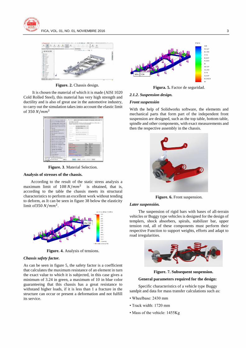
Figure. 2. Chassis design.
It is chosen the material of which it is made (AISI 1020
Cold Rolled Steel), this material has very high strength and
ductility and is also of great use in the automotive industry,
to carry out the simulation takes into account the elastic limit
of 350 𝑁/𝑚𝑚2
Figure. 3. Material Selection.
Analysis of stresses of the chassis.
According to the result of the static stress analysis a
maximum limit of 108 𝑁/𝑚𝑚2 is obtained, that is,
according to the table the chassis meets its structural
characteristics to perform an excellent work without tending
to deform, as It can be seen in figure 38 below the elasticity
limit of350 𝑁/𝑚𝑚2.
Figure. 4. Analysis of tensions.
Chassis safety factor.
As can be seen in figure 5, the safety factor is a coefficient
that calculates the maximum resistance of an element in turn
the exact value to which it is subjected, in this case gives a
minimum of 3.24 in green, a maximum of 10 in blue color
guaranteeing that this chassis has a great resistance to
withstand higher loads, if it is less than 1 a fracture in the
structure can occur or present a deformation and not fulfill
its service.
Figura. 5. Factor de seguridad.
2.1.2. Suspension design.
Front suspensión
With the help of Solidworks software, the elements and
mechanical parts that form part of the independent front
suspension are designed, such as the top table, bottom table,
spindle and other components, with exact measurements and
then the respective assembly in the chassis.
Figure. 6. Front suspension.
Later suspensión.
The suspension of rigid bars with bases of all-terrain
vehicles or Buggy type vehicles is designed for the design of
templers, shock absorbers, spirals, stabilizer bar, upper
tension rod, all of these components must perform their
respective Function to support weights, efforts and adapt to
road irregularities.
Figure. 7. Subsequent suspension.
General parameters required for the design:
Specific characteristics of a vehicle type Buggy
sandpit and data for mass transfer calculations such as:
• Wheelbase: 2430 mm
• Track width: 1720 mm
• Mass of the vehicle: 1455Kg

4 J. PÉREZ, A. TORRES, C. MAFLA
• Total mass: 1605 kg (considering two passengers)
• Distance to floor: 300mm
• Center of gravity height: 528mm (with the help of
Solidworks software)
2.1.3 Transfer of masses.
The transfer of masses are the moments acting in the
center of gravity of the vehicle and are transferred from one
wheel to another when there is direct contact of the tires with
the ground due to acceleration, braking or changing
direction as a curve, This phenomenon can be identified by
the driver of the vehicle.
Aerodynamic loads are considered despicable, as their
tubular structure and the speeds attained do not generate
great influences on the vehicle. For this reason, the structure
will be subjected to the following loads:
• Permanent loads (G), which refer to the weight of the
vehicle and the occupants.
• Variable loads (Q), which refer to loads generated by
inertia when accelerating, braking or bending.
These loads are multiplied by a recommended load
factor in order to guarantee the design and durability of the
components to be evaluated:
• The permanent loads will have a factor of 𝜸𝑮 = 1.33
• Variable loads will have a factor of 𝜸𝑸 = 1.50
This is also the analysis of mass transfer in the most
extreme conditions, such as acceleration, sudden braking
and vehicle in a curve with a high speed of 60km / h in a
turning radius of 50m, where the vehicle is forced to check
Strength, durability of its components for safe and efficient
driving.
a. Mass transfer during acceleration.
Vehicle acceleration is required, and the time it takes
to travel a distance, in this case a speed of 0 to 100 km / h in
9.9 seconds is used that comes from the Ford Explorer 4.0 L
V6 ( 160 HP), therefore:
𝑣 = 𝑣0 + 𝑎. 𝑡
𝑎 =𝑣
𝑡
𝑎 =27.78
9.9
𝑎 = 2.8 𝑚𝑠2⁄
This acceleration result 2.8 𝑚𝑠2⁄ , is subsequently
used in the formula to calculate mass transfer during
acceleration which is determined as follows:
𝑤𝑎 =𝑎 ∗ 𝑚 ∗ ℎ
𝑙
Where:
𝑤𝑎 = Transfer of mass (N)
𝑎 = Acceleration (m/s2)
𝑚 = Total mass (kg)
ℎ = Height of the center of mass (m)
𝑙 = Wheelbase (m)
𝑤𝑎 =2.8 ∗ 1605 ∗ 0.528
2.430
𝑤𝑎 = 976.5 𝑁
It is considered that the mass distribution of the vehicle
type Buggy is 60% in the front and 40% in the back
approximately, in acceleration is calculated in the posterior
axis in turn uses mass transfer 𝑤𝑎 = 976.5 𝑁 since the loads
at the moment of acceleration tend to go backwards the load
on the rear axle is:
𝑤𝑡 = (𝑚 ∗ 40% ∗ 𝑌𝑔) + (𝑊𝑎
𝑔∗ 𝑌𝑞)
𝑤𝑡 = (1605 ∗ 0.4 ∗ 1.33) + (976.5
9.81∗ 1.5)
𝑤𝑡 = 1003.2 𝐾𝑔
In acceleration has a load on the rear axle of 1003.2 kg,
dividing you get 501.6 kg on each wheel and on the front
axle 1131. 45 kg giving 565.73 kg for each wheel, adding
the loads should result in 2134.65 kg Is the total weight
multiplied by the load factor, 𝜸𝑮 = 1.33.
b. Mass transfer during sudden braking.
It is necessary to find the braking distance, ie the distance
traveled by the vehicle from the activation of the brakes to
their complete stop. This distance is obtained from the
following expression:
𝑑𝑓 =𝑣2
254𝑒
Where:
𝑑𝑓 = Braking distance (m)
𝑣 = Speed at braking (km/h)
𝑒 = Coefficient of friction pneumatic-soil.
𝑑𝑓 =1002
254 ∗ 0.85
𝑑𝑓 = 46.31𝑚
The maximum deceleration caused by braking is:
𝑎𝑓 =𝑣2
2 ∗ 𝑑𝑓
𝑎𝑓 =27.782
2 ∗ 46.31
𝑎𝑓 = 8.33𝑚/𝑠2

FICA, VOL. 01, NO. 01, NOVIEMBRE 2016 5
The mass transfer during braking is:
𝑤𝑓 =𝑎 ∗ 𝑚 ∗ ℎ
𝑙
Where:
𝑤𝑓 = Transfer of mass (N)
𝑎 = Acceleration (m/s2)
𝑚 = Total mass (kg)
ℎ = Height of the center of mass (m)
𝑙 = Wheelbase (m)
𝑤𝑓 =8.33 ∗ 1605 ∗ 0.528
2.430
𝑤𝑓 = 2905 𝑁
Mass transfer results in 𝑤𝑓 = 2905 𝑁, this formula
uses the braking acceleration and other known data, in the
front there is greater weight by the location of its
components in the front axle 60%, this result is applied in
the formula of mass transfer over braking already that the
loads go forward.
𝑤𝑡 = (𝑚 ∗ 60% ∗ 𝑌𝑔) + (𝑊𝑓
𝑔∗ 𝑌𝑞)
𝑤𝑡 = (1605 ∗ 0.6 ∗ 1.33) + (2905
9.81∗ 1.5)
𝑤𝑡 = 1725 𝐾𝑔
When braking, a full load is obtained on the front axle
𝑤𝑡 = 1725 𝐾𝑔, dividing 862.5 kg in each wheel, in the front
axle and 409.65 kg as a result 204.83 for each wheel in the
rear axle, summing the loads the result is 2134.65 kg which
is the total weight multiplied by the load factor 𝜸𝑮 = 1.33
c. Transfer of mass during a curve
When passing through a curve, forces are generated
that produce the transfer of load from the internal wheels to
the external ones. It is considered that the vehicle enters a
50m radius curve with a maximum speed of 60km / h, for
which the normal acceleration generated is calculated:
𝑎𝑛 =𝑣2
𝜌
Where:
𝑎𝑛 = Normal acceleration (m/s2)
𝑣 =Speed (m/s)
𝜌 = Radius of the curve (m)
𝑎𝑛 =16.662
50
𝑎𝑛 = 5.5 𝑚/𝑠2
The mass transfer during the curve is determined by:
𝑤𝑙 =𝑎𝑛 ∗ 𝑚 ∗ ℎ
𝑏
Where:
𝑤𝑙 = Transfer of lateral mass (N)
𝑎𝑛 = Normal acceleration (m/s2)
𝑚 = Mass (kg)
ℎ = Height of the center of mass (m)
𝑏 = track width (m)
𝑤𝑙 =5.5 ∗ 1605 ∗ 0.528
1.720
𝑤𝑙 = 2709.8 𝑁
In mass transfer during a curve is made a very clear
example to take data that is needed as is the case of normal
acceleration 𝑎𝑛 = 5.5 𝑚/𝑠2 In turn the lateral mass transfer
was obtained 𝑤𝑙 = 2709.8 𝑁, which is used in the general
formula applying both the front and rear axles 60% - 40%.
Front Axle:
𝑤𝑑 = (1605 ∗ 0.3 ∗ 1.33) ± (2709.8
9.81∗ 1.5)
𝑤𝑑1 = 1054.7 𝐾𝑔
𝑤𝑑2 = 226 𝐾𝑔
In the front axle there is 60% due to the location of its
components. In addition, the calculations are performed on
each wheel where 30% is used for the distribution of loads
at rest, the inner wheel receives greater side load transfer
𝑤𝑑1 = 1054.7 𝐾𝑔, and in the external 𝑤𝑑2 = 226 𝐾𝑔.
Rear Axle:
𝑤𝑑 = (1605 ∗ 0.2 ∗ 1.33) + (2709.8
9.81∗ 1.5)
𝑤𝑑3 = 841.3 𝐾𝑔
𝑤𝑑4 = 12.6 𝐾𝑔
On the rear axle there is 40% since the weight of its
components is less for calculations 20% is used for each
wheel by the distribution of loads at rest, the inner wheel
receives greater side load transfer 𝑤𝑑3 = 841.3 𝐾𝑔, and in
the external 𝑤𝑑4 = 12.6 𝐾𝑔.
Analysis of load on each wheel
From the calculated values the following analysis is
performed for each wheel under the different driving
situations, consider that the total weight of the vehicle will
be multiplied by the permanent load factor of 1.33, adding
the loads on the four wheels of the vehicle in all positions
The total weight is obtained.
Ec.9

6 J. PÉREZ, A. TORRES, C. MAFLA
Total weight =1605kg * 1.33= 2134.65 Kg
Table 1. Load analysis.
As can be seen in Table 1, where there is a greater load is
when the vehicle takes a curve and all the weight is directed
to the inner wheels obtaining as a result in L1 1054.7 kg and
L2 841.3 kg, all this is given by the speed and The turning
radius having a curve.
2.1.4 Analysis of the elements of the suspension system.
Analysis of suspension arms.
In curve. For the analysis, it is taken into account the
greater load of those calculated in several driving conditions
Front top table.
Selection of material.
Before conducting the analysis of the front top table,
the material in this case (ductile iron) with elastic limit of
551 𝑁/𝑚2, is selected, as shown in Figure 8, to verify if the
characteristics of this element support the Tensions to which
they are subjected (Mott, 2006)
Figure 8. Application of material.
Source: (Solidworks, 2016)
Application of forces at fixed and moving points.
𝐹 = 1054.7𝑘𝑔 ∗ 9.81𝑚/𝑠2
𝐹 = 10346.7𝑁
Figure 9. Determination of points of attachment and
application of forces.
Source: (Solidworks, 2016)
The highest force that is used is the one supported
during a curve that is obtained from the analysis of loads in
this case 1054.7 kg that is multiplied by gravity to obtain the
total force since the weight is going to be directed to the rim
depending the inclination of The road, in this step before
performing the analysis should fix the moving and fixed
points in addition the direction of the arrows as the force is
applied.
Static stress analysis.
When static stress analysis is performed according to (-
VonMises-), the mesh must be applied to the element, that
is, a set of finite elements divided on the part.
Figure 10. Tensions on the front upper suspension table.
Source: (Solidworks, 2016)
The elastic limit of the material is 551MPa, the analysis
results in the maximum tensile strength of 141 MPa, when
the maximum elastic limit is exceeded, the part will become
deformed or a break point will occur. In this case, the part
fulfills the function Required and its material is resistant to
loads and stresses to be subjected.
Security factor.
The top table has an adequate safety factor of 3.92.
Figure 11. Safety factor on the front top suspension
table
Source: (Solidworks, 2016)

FICA, VOL. 01, NO. 01, NOVIEMBRE 2016 7
This mechanical piece fulfills a good performance to
support weight and to adapt to the irregularities of the way,
knowing that the factor of safety always must be greater than
1 if it were smaller the material is deformed and rupture
takes place.
This analysis is performed on each element of the
suspension and then proceed to the assembly to the chassis.
2.1.5 General assembly of the suspensions to the chassis.
Once the Solidworks software has finished designing
the suspensions and checking that all parts comply with the
requirements, the front and rear suspensions and their brake
system components are assembled to put them into practice.
Figure 12. General assembly of the chassis and its
components.
Source: (Solidworks, 2016)
Design of the structure.
Once the installation of the braking, suspension and
steering systems to the chassis has been completed, taking
into account the necessary dimensions of the engine and box,
the bodywork is modified using Solidworks software, taking
as reference the bases of the chassis where it is located The
body.
Figure 12 shows the body of the Peugeot 604 Buggy type
vehicle, which had to be modified in its entirety because it
was not in optimal structural conditions to avoid mechanical
damage to the components and to ensure the safety of the
occupants in the drive.
Figura13. Chassis and body of the vehicle Peugeot 604
type Buggy.
Selection of materials.
The selection of materials is made in a very
professional manner, according to the design and the
characteristics of the manufacturer, so that the body does not
exceed the weight required for this type of sandpit vehicle.
Table 2. Materials used in the reconstruction of the body.
Plaques Noir TOL: 2mm. 3mm.
1/16.
Type de sangles C:
100 X 50 X 15 X 3.00 X 6000mm. 150 X 50 X 15 X 3.00 X 6000mm.
Tube rond: 2” X 2 X 6000mm
tube carré 40 X 40 X 1.50 X 6000 – 1 ½”
Coqueada maille obturateur.
fibre of verre.
Source: (Noboa, 2010.)
In Solidworks software, the design of the structure is
made taking into account measurements at a scale of 1: 2,
such as the track width that is taken from rim to rim
1720mm, The height of the main pair 1819mm and the
length between axles of the vehicle 2430mm, for the
construction of the structure on the bases of the chassis
Figura 14. The basic structure.
Source: (Solidworks, 2016)
Once the structure has been formed, it is necessary to
make the lateral mudguard of the body of the floor, the
cushioned mesh of the front and rear blinds, and finally the
design of the hood with air intake for greater ventilation and
performance in the engine, To lighten the weight its
construction was made in fiberglass, according to the vehicle
type Buggy.
Figure 15. Final Body.
Source: (Solidworks, 2016)
This is the overall design of the prototype after the
general assembly is done with all its components, such as the
chassis the front and rear suspensions, brake system, steering
system, bodywork as well aesthetic components of a
prototype Buggy, once ready The design plans are to be put
into practice.

8 J. PÉREZ, A. TORRES, C. MAFLA
Figura 16. Ensamble general del prototipo Buggy.
Fuente: (Solidworks, 2016)
3. Results
3.1 Construction..
For the construction of the vehicle, the
aforementioned materials were used, see Table 3, in addition
to the multiple machines and tools needed for the re-
construction of the new Ford Buggy, all this was done in a
mechanical workshop of modifications specialized in this
type of vehicles .
Table 3. Machines and Tools.
MACHINES.
Welds:
Gas arc welding (MIG).
Electrical
autogenous
Benders: Tube.
Tol.
Plasma cutter.
Pedestal drill.
Compressor.
Lathe.
Circular saw.
TOOLS.
Drill. Game of cracks.
Polisher. Iron saw
Set of keys. Buril.
Hammer. Support levers.
Screwdrivers. Hydraulic jack.
Flat and round files. Scissors for metal.
Manual press. Flexometer
MATERIALS.
Electrodes: 6011.
6013.
Cebora.
Discs: Cutting.
Polish.
Wire for MIG.
It uses the planes that were obtained from the design
made in Solidworks software, proceed to build the body,
used various machines such as welding (MIG), plasma cutter
and tools necessary to carry out this process of
reconstruction Of this vehicle.
Figure 17. Principle of construction of the body.
Finished the construction of the body of the fenders,
side cans blind mesh front and rear, also made the bonnet in
fiberglass, for mounting also fixing other components of the
carrier leaving the vehicle ready for the process Of paint.
Figure 18. Finished body assembled to the chassis.
Buggy vehicle finished with all its components in perfect
condition and ready to undergo any test, in addition this
prototype should serve as study material for the students of
the Race of Engineering in Automotive Maintenance, in the
Technical North University.
Figure 19. Buggy Ford prototype.
CONCLUSIONS Solidworks software was designed in the chassis
with all its components such as struts, crossbars,
bases and supports where the body is housed, the
material of construction is AISI 1020 Cold rolled
steel with elastic limit of 350 𝑁/𝑚𝑚2, through the
stress analysis it was possible to determine that the
maximum limit is 108 𝑁/𝑚𝑚2, applying a
distributed force of 16000 N, in turn the safety

FICA, VOL. 01, NO. 01, NOVIEMBRE 2016 9
factor gives a minimum of 3.24, guaranteeing the
application of this chassis in the prototype Buggy.
It was determined that with the installation of
systems such as: brakes, suspension and steering
for the chassis must take into account the weight of
the vehicle 1455kg, the force that will exist when
producing the braking in the front 1725 kg and later
409, 66 kg by calculating mass transfer by adding
the loads gives a result of 2134.65 kg which is
equivalent to the weight of the vehicle multiplied
by the load value Yg = 1.33, in this way it is
determined that the materials applied in each
system are efficient Giving safety, reliability and
comfort when driving the prototype Buggy.
Through the Matlab software, the simulation of the
posterior suspension was performed, where the
oscillations of the suspension can be seen and the
time it takes to return to its initial position, for this
simulation the coefficient of elasticity of the spring
Kw: 6730109 [N/m] and the coefficient of
damping Ks: 835054[N/m], It is determined that
the choice of materials and modification of the rigid
axle suspension with tie rods fulfill their support
function.
The solidworks software determines the maximum
loads supported on the components of the vehicle,
a structural modeling, a visualization of the Buggy
vehicle with the assembly of all its systems in three
dimensions, being able to determine the plans to
carry out the construction of the same.
The mechanical tests performed on the Buggy
prototype revealed the efficient work of the same in
the design and construction phase, achieving
safety, reliability and comfort when driving.
Thanks
First we want to thank God for allowing us to be alive,
healthy, and give us all his love to share this achievement
with the people we love the most.
To the Technical University of the North and its teachers
who through their knowledge were able to guide us in the
best way in the culmination of our university career.
To Mr. Carlos Mafla Msc. Director of the Project, who
shared his knowledge, for his patience and confidence
offered to complete this work of degree.brindada para poder
culminar este trabajo de grado.
Bibliographic references
[1] Alerco. (2009). Blogicars. Recuperado el 18 de Noviembre de 2015,
de http://www.blogicars.com/2013/06/%C2%BFque-son-los-
frenos-hidraulicos/
[2] Alonso, J. (2011). Técnicas del AUTOMÓVIL CHASIS. Madrid,
España: Paraninfo.
[3] Astudillo, M. O. (2010). Tecnología del automóvil. Madrid, España: Paraninfo.
[4] Casado, E. Á., Navarro, J. M., & Morales, T. G. (2012). Sistema De Transmisión Y Frenado. Madrid, España: Paraninfo.
[5] Casado, E. Á., Navarro, J. M., & Morales, T. G. (2012). Sistemas de
transmisión de fuerzas y trenes de rodaje. Madrid, España: Paraninfo.
[6] Domínguez, E. J., & Ferrer, J. (2012). Circuitos de Fluidos.
Suspensión y Dirección. Madrid, España: MACMILLAN IBERIA, S.A.
[7] Ford. (2016). Mecanico Automotriz.org. Recuperado el 13 de 06 de
2016, de Ingeníeria Extrema: http://www.mecanicoautomotriz.org/1080-manual-informacion-
general-chasis-ford-explorer-sistemas-frenos-partes
[8] Kindelán, D. J. (5 de Enero de 2015). Fundacion CEA. Recuperado el 17 de Noviembre de 2015, de Comisariado Eurpoeo del
Automóvil: http://www.fundacioncea.es/
[9] Lenis, I. M. (2003). Manual de Servicio. En F. M. Company, EVTM (págs. 502-02-i). PCED.
[10] Martínez, D. H. (2012). Manual Práctico Del Automóvil. Madrid,
España: Cutural, S.A.
[11] meganeboy., D. (2014). Aficionados a al Mecánica. Recuperado el
18 de Noviembre de 2015, de
http://www.aficionadosalamecanica.net/direccion-geometria.htm
[12] Moler, C. (2013). Software MATLAB. España.
[13] Mott, R. L. (2006). Diseño de elementos de máquinas. PEARSON
EDUCACIÓN, MÉXICO.
[14] Noboa, N. &. (2010.). Comercio e Ingenieria . Recuperado el 15 de
Junio de 2016, de http://www.nyn-ec.com/tol---planchas.html
[15] Nogales, M. (2008). Actualidad Motor. Recuperado el 18 de Noviembre de 2015, de AB Internet Networks:
http://www.actualidadmotor.com/es-hora-de-realizar-una-
alineacion-de-nuestro-coche-parte-ii/
[16] Nord, V. (16 de 05 de 2016). Autodata 3.0. Inglaterra, France.
[17] Ray, J. (2010). Guía del estudiante para el aprendizaje del software
SolidWorks. Recuperado el 01 de 06 de 2016, de https://www.solidworks.com/sw/docs/Student_WB_2011_ESP.pdf
[18] Rondón., N. (2012.). Miller Manual Reparación De Automóviles.
Barcelona., España.: Grafos S.A.
[19] Solidworks. (18 de Marzo de 2016). CAD. EE.UU.
[20] Tektino. (2016). Autech Tools. Recuperado el 1 de 06 de 2016, de
Automotive Technology: http://www.autech.com.ec/index.php/productos/alineacion/alinead
ora-de-ruedas-autoboss-tektino-detail
[21] Wladimir, M. A.-T. (2008). Repositorio Digital UTN. Recuperado el 12 de 04 de 2016, de
http://repositorio.utn.edu.ec/bitstream/123456789/1654/1/FECYT
%201250%20TESIS.pdf

10 J. PÉREZ, A. TORRES, C. MAFLA
About the Authors ...
Author-Jefferson PÉREZ B. Was born in the city of
Tulcán on September 21, 1992.
He completed his primary studies at the "Santa Mariana de
Jesus" school in Huaca. His secondary studies in the
Technological Institute Vicente Fierro, in the specialty of
Automotive Mechanics. He is currently a graduate of the
Technical University North in the career of Engineering in
Automotive Maintenance
Author-Andrés TORRES R. Was born in the city of Ibarra
on October 2, 1992.
He completed his primary studies at the "La Salle" school in
Ibarra. His secondary studies in the Military Academy "San
Diego", in the specialty of Physical Mathematician. He is
currently a graduate of the Technical University of North in
the career of Engineering in Automotive Maintenance
Co-author Carlos MAFLA. Was born in the city of Ibarra
on April 20, 1986.
He attended his secondary studies at the "La Salle" school
Ibarra, his undergraduate studies at the Technical University
of North, obtaining the title of Engineer in Automotive
Maintenance. The postgraduate studies were carried out at
the University of the Armed Forces - Quito (ESPE), where
he obtained the title of Magister in Renewable Energies,
specializing in Biofuels. He is currently a research professor
at the Technical University of North, where he promotes the
use of Biofuels through his research projects.