Transmision y Distribucion Siemens
51
14 Siemens Energy Sector Power Engineering Guide Edition 7.0
-
Upload
david-jose-poma-guillen -
Category
Documents
-
view
230 -
download
1
Transcript of Transmision y Distribucion Siemens

7/22/2019 Transmision y Distribucion Siemens
http://slidepdf.com/reader/full/transmision-y-distribucion-siemens 1/5014 Siemens Energy Sector Power Engineering Guide Edition 7.0

7/22/2019 Transmision y Distribucion Siemens
http://slidepdf.com/reader/full/transmision-y-distribucion-siemens 2/5015Siemens Energy Sector Power Engineering Guide Edition 7.0
Power Transmission and Distribution Solutions
2
2.1 Overview of Technologies and Services 16
2.1.1 Solutions for Smart and Super Gridswith HVDC and FACTS 16
2.1.2 AC/DC Transmission and Distribution 16
2.1.3 Managing Entire Projects 18
2.1.4 Partners Throughout the System Life Cycle 18
2.2 High-Voltage Direct-Current Transmission 19
2.2.1 Siemens HVDC Technologies 19
2.2.2 Main Types of HVDC Schemes 19
2.2.3 LCC HVDC – The “Classical” Solution 20
2.2.4 Ultra-HVDC Transmission (UHV DC) Bulk Power 21
2.2.5 HVDC PLUS – One Step Ahead 21
2.2.6 Siemens HVDC Control System: Win-TDC 22
2.2.7 Services 23
2.3 Medium-Voltage DC Links with SIPLINK 24
2.3.1 Shore-to-Ship Connection 24
2.3.2 Power Transfer Between Distribution Networks 25
2.3.3 High Availability of Industrial Networks 26
2.4 Flexible AC Transmission Systems 27
2.4.1 Parallel Compensation 27
2.4.2 Series Compensation 29
2.5 Power Transmission Lines 30
2.5.1 Gas-Insulated Transmission Lines 30
2.5.2 Overhead Lines 34
2.6 Grid Access Solutions forDecentralized Power Generation 48
2.6.1 References 50
2.7 Solar Power Solutions 54
2.8 SIESTORAGE 56
2.8.1 The Modular Energy Storage Systemfor a Sustainable Energy Supply 56
2.8.2 Spot-on for a Wide Variety of Applications 58
2.8.3 The Solution Providerfor Energy Storage Solutions 59
2.9 SIEHOUSE 60
2.9.1 Compact, Mobile Plug-and-Play E-Housesfor Power Distribution 60
2.9.2 Spot-on for a Broad Range of Applications 61
2.9.3 It is All about the Best Design 62
2.9.4 Completely Integrated Solutionsfrom a Single Source 63

7/22/2019 Transmision y Distribucion Siemens
http://slidepdf.com/reader/full/transmision-y-distribucion-siemens 3/5016 Siemens Energy Sector Power Engineering Guide Edition 7.0
2 Power Transmission and Distribution Solutions
Smart grids will help achieve a sustainable development. It is
worthwhile mentioning that the smart grid vision is in the same
way applicable to the system developments in other regions of the
world. Smart grids will help achieve a sustainable development.
An increasingly liberalized market will encourage trading oppor-
tunities to be identified and developed. Smart grids are a neces-
sary response to the environmental, social and political demands
placed on energy supply.
2.1.2 AC/DC Transmission andDistribution
HVDC, FACTS and SIPLINK
Today’s power transmission systems have the task of transmitting
power from point A to point B reliably, safely and efficiently. It is
also necessary to transmit power in a manner that is not harmful
to the environment. Siemens offers comprehensive solutions,
technical expertise and worldwide experience to help customers
meet these challenges.
For each application and technical transmission stage, Siemens
offers optimized solutions with SIPLINK (Siemens Multifunctional
Power Link), HVDC transmission or FACTS for the most efficient
use of AC power systems and lines.
Typical applications for FACTS include fast voltage control,
increased transmission capacity over long lines, power flow
control in meshed systems, and power oscillation damping. With
FACTS, more power can be transmitted within the power system.
When technical or economical feasibility of conventional three-
phase technology reaches its limit, HVDC will be the solution
(fig. 2.1-2). Its main application areas are economical transmis-
sion of bulk power over long distances and interconnection of
asynchronous power grids. Siemens‘s latest innovation in high-
voltage direct current technology is HVDC PLUS. The advantages
of the new system, which employs voltage-sourced converters,
include a compact layout of the converter stations and advanced
control features such as independent active and reactive power
control, and black start capability.
For medium-voltage DC transmission, Siemens offers the SIPLINK
system. Depending on the application and the configuration of
the existing system, SIPLINK will reduce investment, system and
lifecycle costs. The system controls the active power and opti-
mizes voltage stability by providing reactive power (section 2.3).
2.1 Overview ofTechnologies and Services
Feeding the power generated at different locations over long
distances into power systems often calls for extraordinary power
transmission and distribution solutions. Despite the challenges it
poses, however, interconnecting of different regions, countries
or even continents remains a viable option for providing these
areas with economical access to power (fig. 2.1-1). As a solution
provider with extensive experience in every aspect of power
transmission and distribution, Siemens has already implemented
a large number of projects linking power systems or connecting
decentralized generating units to the grid. In each case, condi-
tions were unique. And because Siemens strives to provide its
customers with the most cost-efficient results, the implemented
solutions using different technologies were also unique.
2.1.1 Solutions for Smart and SuperGrids with HVDC and FACTS
The power grid of the future must be secure, cost-effective and
environmentally compatible. The combination of these three
tasks can be tackled with the help of ideas, intelligent solutions
as well as advanced technologies.
Innovative solutions with HVDC (High-Voltage Direct Current
Transmission) and FACTS (Flexible AC Transmission Systems)
have the potential to cope with the new challenges. By means of
power electronics, they provide features which are necessary to
avoid technical problems in the power systems, they increase
the transmission capacity and system stability very efficiently
and help to prevent cascading disturbances.
The vision and enhancement strategy for the future electricity
networks are, for example, depicted in the program for “Smart
Grids”, which was developed within the European Technology
Platform.
Features of a future smart grid such as this can be outlined as
follows:
Flexible: fulfilling operator needs whilst responding to the
changes and challenges ahead
Accessible: granting connection access to all network users,
particularly for RES and high-efficiency local generation with
zero or low carbon emissions
Reliable: assuring and improving security and quality of supply
Economic: providing best value through innovation, efficient
energy management and “level playing field” competition and
regulation
7/22/2019 Transmision y Distribucion Siemens
http://slidepdf.com/reader/full/transmision-y-distribucion-siemens 4/50
Power Transmission and Distribution Solutions
17Siemens Energy Sector Power Engineering Guide Edition 7.0
2
Power lines
Since the very beginning of electric power supply, overhead lines
have constituted the most important component for transmission
and distribution systems. Their portion of the overall length of
electric circuits depends on the voltage level and on local condi-
tions and practice. When environmental or structural factors make
overhead lines impossible, Siemens‘s “underground” transmission
path is the ideal solution. Siemens gas-insulated transmission
lines (GIL) are an economically viable alternative to conventional
power cables (section 2.5).
Grid access
Decentralized generating units are custom-engineered, which
involves reconciling contrasting parameters, such as high reli-
ability, low investment costs and efficient transmission, in the
best possible solution. Specific attention is paid to intelligently
designing the “collection systems” at the medium-voltage level,
which is followed by the high-voltage transmission system
offering the grid access. By relying on both transmission technol-
ogies, Siemens can offer AC as well as DC solutions at both the
high and medium-voltage levels (section 2.6).
Solar power
As an alternative power supply for rural electrification, Siemens
integrates solar power in the low-voltage distribution system for
private consumers, as stand-alone systems or even with grid
connection (section 2.7).
Investmentcosts Total
AC
costsBreak-even distance
DC terminal costs
AC terminal costs –including grid transformers
TotalDCcosts
DC linecosts
AC linecosts
Transmission distance
* SSC = Series and shunt compensation of AC lines – required for each section of the line
2xSSC*
2xSSC*
Fig. 2.1-2: AC versus DC transmission cost over distance.
The break-even distance amounts to 600 km for
a power transmission of 1,000 MW
Symbols: TPSC/TCSC DC transmissionand interconnection
North system50 Hz
South system60 Hz
Central system60 Hz
Clean andlow-costenergy
Industrialenergy supply
Tariff
Tariff
Powerexchange
Power exchange– Asynchronous networks
Avoidance of
loop flows
Short-circuitcurrent limiter
Cleanenergy
SVC FSC B2B as GPFC HVDC PLUS
Bulk power andlong distance
S C C L Submarine
cable links
Fig. 2.1-1: Power transmission and distribution solutions
2.1 Overview of Technologies and Services

7/22/2019 Transmision y Distribucion Siemens
http://slidepdf.com/reader/full/transmision-y-distribucion-siemens 5/50
Power Transmission and Distribution Solutions
18 Siemens Energy Sector Power Engineering Guide Edition 7.0
2.1.3 Managing Entire Projects
Project management
Supplying power is more than just combining a number of
individual components. It calls for large-scale projects, such as
transmission systems or industrial complexes, especially in
countries where the demand for power is growing at an acceler-
ated pace. The best partner to handle such large projects is an
expert who can carefully analyze the demand, take an integrated
approach to project planning and consider all the general condi-
tions. A qualified project partner is one that can provide high-
quality components and services for both power transmission
tasks and power system management. Such a partner also can
ensure that the systems are installed expertly.
Turnkey solutions
Siemens‘s many years of experience al low it to offer turnkey
power transmission solutions that are tailored to individual
requirements. Siemens supplies all components, including
power plants, AC or DC transmission systems and high-voltage
interconnected power systems with high, medium and low
voltage that finally reach the individual customers. What makes
these turnkey solutions so attractive is that one party is respon-
sible for coordinating the entire project, thereby reducing the
number of interfaces between system operator and supplier to a
bare minimum. Turnkey projects also reduce the operator‘s own
share in project risks, since Siemens is responsible for delivering
a system that is ready for operation.
Engineering, procurement, production and construction
In addition to comprehensive planning and management ser-
vices, engineering is one of Siemens‘s special strengths. Siemens
can produce or procure all necessary components and perform
all construction work up to testing, commissioning and putting
an entire system into operation. With Siemens as a partner,
companies can benefit from Siemens‘s extensive manufacturing
expertise and from the work of experienced Siemens engineers
who have already participated in a wide range of projects world-
wide. Working on this basis, Siemens can provide the best
technology for projects based on proprietary Siemens compo-
nents and additional hardware purchased from reputable ven-
dors. Siemens experts have the important task of determining
which of the various technical options are best suited for imple-
menting the project. They consider transmission capacity,
transmission efficiency and the length of the transmission line,
and after the best technical solution has been determined, they
assess its long-term cost efficiency for the operator. Only then
can the actual implementation begin for installation and on-time
commissioning.
Maintenance
Systems will operate at their best, when equipment lasts a long
time and provides continuous trouble-free operation. The
Siemens maintenance service ensures that all components are
always running safely and reliably. Siemens continuously main-
tains operator systems through regular inspections including all
switchgear and secondary technology. If a malfunction occurs
during operation, Siemens is immediately on the job; support is
available 24 hours a day, 365 days a year. And with the increased
use of state-of-the-art online monitoring and remote diagnosis
systems, Siemens offers additional possibilities for keeping
operating costs to a minimum.
Optimization and modernization
No company can replace its equipment and systems fast enough
to keep pace with technological progress. But all companies can
take advantage of the latest technological opportunities through
the variety of optimization options provided by the Siemens
retrofit and upgrade service. This fast and economical solution
allows customers to invest their capital wisely and take full
advantage of Siemens‘s experience in adapting older systems to
new technical standards.
2.1.4 Partners Throughout the SystemLife Cycle
Siemens is with system operators every step of the way to help
them develop their projects, to create financing solutions and to
provide project management (fig. 2.1-3), and supports them
beyond engineering, production and construction. This support
continues as the system is commissioned, as customers need
maintenance services and even when it is time to modernize.
The partnership between Siemens and the system operators
does not stop when a turnkey job is finished: Siemens accompa-
nies the system operators throughout the entire life cycle of
their systems, offering a wide range of services with products of
the highest quality that are always based on the most durable
technologies.
Fig. 2.1-3: Siemens services for the entire system life cycle
Development phase3 years
Financial close
Implementation phase3 years
Start ofcommercial use
Operation25 years
Maintenance and after-sales services
Overall project management
Engineering
Basic design
Conceptual design
Detailed design
Procurement
Manufacturing
Global sourcing
Local sourcing
Construction
Erection
Commissioning
Training
Technical advice Feasibility study
Performances values:LossesReliabilityAvailability
Design transmissionsystem
Financial advice
Economical assessment
Feasibility study
Flexibility
Rentability
Estimates
Bankability
Capabilities for project development, implementation and operation
2.1 Overview of Technologies and Services
For further information:
http://www.siemens.com/energy/power-transmission-solutions
http://www.siemens.com/energy/hvdc-facts-newsletter
7/22/2019 Transmision y Distribucion Siemens
http://slidepdf.com/reader/full/transmision-y-distribucion-siemens 6/50
Power Transmission and Distribution Solutions
19Siemens Energy Sector Power Engineering Guide Edition 7.0
2
2.2 High-Voltage Direct-Current Transmission
Siemens HVDC transmission is used when technical and/or
economical feasibility of conventional high-voltage AC transmis-
sion technology have reached their limits. The limits are over-
come by the basic operation principle of an HVDC system, which
is the conversion of AC into DC and viceversa by means of high
power converters.
Featuring its fast and precise controllability, a Siemens HVDC can
serve the following purposes:
Transmission of power via very long overhead lines or via long
cables where an AC transmission scheme is not economical or
even not possible
Transmission of power between asynchronous systems
Exact control of power flow in either direction
Enhancement of AC system stability
Reactive power control and support of the AC voltage
Frequency control
Power oscillation damping
2.2.1 Siemens HVDC Technologies
Depending on the converter type used for conversion between
AC and DC, two technologies are available:
Line Commutated Converter technology (LCC) based on
thyristor valves
Voltage Sourced Converter technology (VSC) based on IGBT
valves, also known as HVDC PLUS
Both technologies enable Siemens to provide attractive solutions
for most challenging transmission tasks ranging from extra high
voltage bulk power transmission to the connection of systems in
remote locations to main grids; from long distance overhead line
or cable to interconnection of two systems at one location.
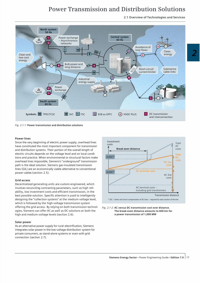
2.2.2 Main Types of HVDC Schemes
The main types of HVDC converters are distinguished by their DC
circuit arrangements (fig. 2.2-1), as follows:
Back-to-back:
Rectifier and inverter are located in the same station. These
converters are mainly used:
To connect asynchronous high-voltage power systems or
systems with different frequencies
To stabilize weak AC links
To supply more active power where the AC system already is at
the limit of its short circuit capability
For grid power flow control within synchronous AC systems
Cable transmission:
DC cables are the most feasible solution for transmitting power
across the sea to supply islands/offshore platforms from the
mainland and vice versa.
Long-distance transmission:
Whenever bulk power is to be transmitted over long distances,
DC transmission is the more economical solution compared to
high-voltage AC.
Back-to-backstation
AC AC
Submarine cable
transmission
Long-distanceOHL transmission
AC AC
AC AC
DC Cable
DC Line
Fig. 2.2-1: Overview of main power transmission applications with
HVDC

7/22/2019 Transmision y Distribucion Siemens
http://slidepdf.com/reader/full/transmision-y-distribucion-siemens 7/50
Power Transmission and Distribution Solutions2.2 High-Voltage Direct-Current Transmission
20 Siemens Energy Sector Power Engineering Guide Edition 7.0
2.2.3 LCC HVDC –The “Classical” Solution
After more than 50 year’s history with Siemens constantly
contributing to its development, LCC HVDC is still the most
widely used DC transmission technology today.
Technology
Thyristor valves
The thyristor valves are used to perform the conversion from AC
into DC and thus make up the central component of the HVDC
converter station. The valves are described by the following
features:
Robust design
Safe with respect to fire protection due to consequent use of
fire-retardant, self-extinguishing material
Minimum number of electrical connections and components
avoiding potential sources of failure
Parallel cooling for the valve levels using de-ionized cooling
water for maximum utilization of the thyristors
Earthquake-proof design as required (fig. 2.2-2)
Direct Light-Triggered Thyristors (LTT) with wafer-integrated
overvoltage protection – the standard solution for transmission
ratings up to 5,000 MW
Electrically triggered thyristors for bulk power transmission up
to 7,200 MW and above
Filter technology
Filters are used to balance the reactive power of HVDC and
power system and to meet high harmonic performance stan-
dards.
Single-tuned, double-tuned and triple-tuned as well as high-
pass passive filters, or any combination thereof, can be
installed depending on the specific requirements of a station.
Active AC and DC filters are available for highest harmonic
performance.
Wherever possible, identical filters are selected maintaining
the high performance even when one filter is switched off.
Applications
The primary application areas for LCC HVDC are:
Economical power transmission over long distances
Interconnection of asynchronous power grids without increase
in short-circuit power
Submarine DC cable transmission Hybrid integration of HVDC into a synchronous AC system for
stability improvement
Increase in transmission capacity by conversion of AC lines into
DC lines
Power ratings
Typical ratings for HVDC schemes include:
Back-to-back: up to typically 1,200 MW
Cable transmission: up to 800 MW per HVDC cable
Long-distance transmission: up to typically 5,000 MW
Fig. 2.2-3: Two times two 400 kV converter systems connected in
series form a ± 800 kV UHV DC station
Fig. 2.2-2: Earthquake-proof and fire-retardant thyristor valves in
long-distance transmission in Guizho-Guangdong, China
7/22/2019 Transmision y Distribucion Siemens
http://slidepdf.com/reader/full/transmision-y-distribucion-siemens 8/50
Power Transmission and Distribution Solutions2.2 High-Voltage Direct-Current Transmission
21Siemens Energy Sector Power Engineering Guide Edition 7.0
2
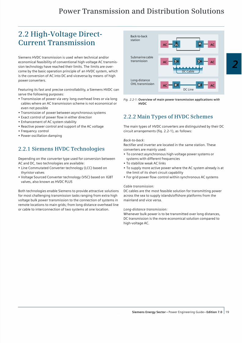
2.2.4 Ultra-HVDC Transmission(UHV DC) Bulk Power
UHV DC from Siemens is the answer to the increasing demand
for bulk power transmission from remote power generation to
large load centers. After having been awarded the contract in
2007, Siemens has successfully commissioned the world’s first
±800 kV UHV DC system with 5,000 MW in China Southern
Power Grid in 2010 (fig. 2.2-3).
Technology
The high DC voltage imposes extreme requirements to the
insulation of the equipment and leads to huge physical dimen-
sions (fig. 2.2-4). The capability to withstand high electrical and
mechanical stresses is thoroughly investigated during the
design. All components are extensively tested to assure that they
withstand most severe operating conditions and meet highest
quality standards.
The thyristor valves are equipped with either 5’’ or 6’’ thyristors
depending on the transmission rating (fig. 2.2-5).
Applications
UHV DC transmission is the solution for bulk power transmission
of 5,000 MW or higher over some thousand kilometers. Com-
pared to a 500 kV LCC HVDC system, the Siemens 800 kV UHV
DC reduces line losses by approx. 60 % – an important aspect
with respect to CO2 reduction and operational cost.
Special attention has to be paid to the corresponding AC networks
that have to supply or absorb the high amounts of electric power.
Power ratings
The Siemens 800 kV HVDC systems are designed to transmit up
to 7,200 MW over long distances.
2.2.5 HVDC PLUS – One Step Ahead
VSC technology offers unique advantages for HVDC transmission
which become more and more important for applications like
connecting remote renewable energy sources, oil and gas
platforms or mines to an existing grid.
Using the latest modular IGBT (Insulated Gate Bipolar Transistor)
technology in a pioneering Modular Multilevel Converter (MMC)
design, Siemens engineers have developed HVDC PLUS as a
landmark product in the evolution of HVDC transmission.
The high power ratings available today make HVDC PLUS increas-
ingly attractive also for projects where LCC HVDC could be used
from a technical perspective.
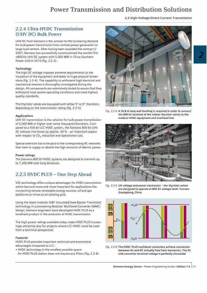
Features
HVDC PLUS provides important technical and economical
advantages compared to LCC:
HVDC technology in the smallest possible space:
An HVDC PLUS station does not require any filters (fig. 2.2-6).
Fig. 2.2-5: UH voltage and power electronics – the thyristor valves
are designed to operate at 800 kV voltage level. Yunnan-
Guangdong, China
Fig. 2.2-4: A 20.8 m long wall bushing is required in order to connect
the 800 kV terminal of the indoor thyristor valves to the
outdoor HVDC equipment and overhead line
1
2
n
1
2
n
U ACU AC
+U d /2
-U d /2
0
Fig. 2.2-6: The HVDC PLUS multilevel converters achieve conversion
between AC and DC virtually free from harmonics. The AC
side converter terminal voltage is perfectly sinusoidal
7/22/2019 Transmision y Distribucion Siemens
http://slidepdf.com/reader/full/transmision-y-distribucion-siemens 9/50
Power Transmission and Distribution Solutions2.2 High-Voltage Direct-Current Transmission
22 Siemens Energy Sector Power Engineering Guide Edition 7.0
Together with a compact design of the MMC, this makes HVDC
PLUS perfectly suitable for offshore platforms or stations with
limited space (fig. 2.2-7, fig. 2.2-8).
Independence from short-circuit capacity:
HVDC PLUS can operate in networks with very low short-circuit
capacity or even in isolated systems with or without own
generation using its black-start capability.
Unipolar DC voltage
The DC voltage polarity is fixed independently from the
direction of power flow. This allows integration into multi-
terminal systems or DC grids. HVDC PLUS can operate with
extruded XLPE or mass-impregnated DC cables.
Economical design and standardization:
The modularly designed HVDC PLUS converter stations can be
perfectly adapted to the required power rating (fig. 2.2-7).
Standard AC transformers can be used, whereas LCC
transformers require special design due to additional stresses
from DC voltage and harmonics.
Applications
HVDC PLUS can be applied in all fields of HVDC transmission –
there are no technical restrictions. The advantages of HVDC PLUS
will be most apparent in circumstances that require the follow-
ing capabilities:
Black start of AC networks
Operation in AC networks with low short-circuit capacity
Compact design, e. g., for offshore platforms
Operation in DC multi-terminal systems or in a DC grid
Power ratings
The design of HVDC PLUS is optimized for power applications in
the range from 30 MW up to 1,000 MW or higher, depending on
the DC voltage.
2.2.6 Siemens HVDC Control System: Win-TDC
The control and protection system is an important element in an
HVDC transmission. The Siemens control and protection system
for HVDC has been designed with special focus on high flexibility
and high dynamic performance, and benefits from the know-
ledge gained from over 30 years of operational experience in
HVDC and related fields of other industries (fig. 2.2-9).
High reliability is achieved with a redundant and robust design.
All control and protection components from the human-machine
interface (HMI), control and protection systems down to the
measuring equipment for DC current and voltage quantities have
been designed to take advantage of the latest software and
hardware developments. These control and protection systems
are based on standard products with a product lifecycle of
25 years or more.
The name Win-TDC reflects the combination of the PC-based HMI
system SIMATIC WinCC and the high-performance industrial
control system SIMATIC TDC.
SIMATIC WinCC (Windows Control Centre) is a PC-based HMI
software for Microsoft Windows that is used for operator control
and monitoring of HVDC systems.
SIMATIC TDC (Technology and Drive Control) is a high-perfor-
mance automation system which allows the integration of both
open-loop and high-speed closed-loop controls within this single
system. It is especially suitable for HVDC (and other power
electronics applications) demanding high-performance closed-
loop control. For extremely fast control functions as required in
HVDC PLUS systems, SIMATIC TDC is complemented by the
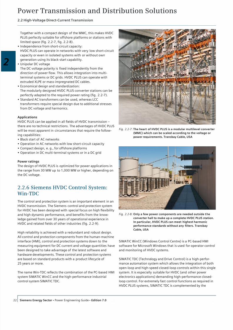
Fig. 2.2-7: The heart of HVDC PLUS is a modular multilevel converter
(MMC) which can be scaled according to the voltage or
power requirements. Transbay Cable, USA
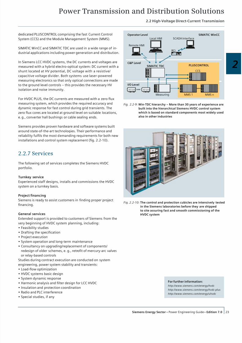
Fig. 2.2-8: Only a few power components are needed outside the
converter hall to make up a complete HVDC PLUS station.
In particular, HVDC PLUS can meet highest harmonic
performance standards without any filters. Transbay
Cable, USA
7/22/2019 Transmision y Distribucion Siemens
http://slidepdf.com/reader/full/transmision-y-distribucion-siemens 10/50
Power Transmission and Distribution Solutions2.2 High-Voltage Direct-Current Transmission
23Siemens Energy Sector Power Engineering Guide Edition 7.0
2PLUSCONTROLSIMATIC TDC
Measuring
Operator Level
C&P Level
I/O Level
I/O Unit I/O Unit
Local HMI
Remote HMI
SCADA Interface
RCI
SIMATIC WinCC
CCS
MMS 1 MMS n
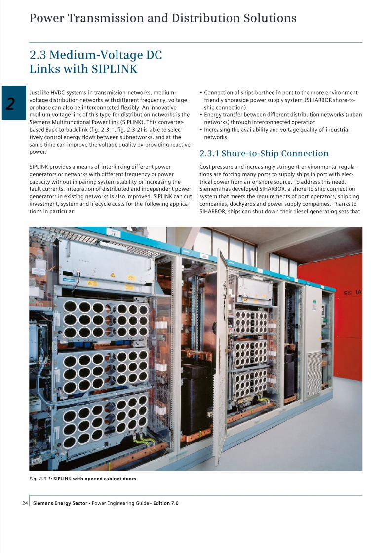
Fig. 2.2-9: Win-TDC hierarchy – More than 30 years of experience are
built into the hierarchical Siemens HVDC control system
which is based on standard components most widely used
also in other industries
Fig. 2.2-10: The control and protection cubicles are intensively tested
in the Siemens laboratories before they are shipped
to site assuring fast and smooth commissioning of the
HVDC system
dedicated PLUSCONTROL comprising the fast Current Control
System (CCS) and the Module Management System (MMS).
SIMATIC WinCC and SIMATIC TDC are used in a wide range of in-
dustrial applications including power generation and distribution.
In Siemens LCC HVDC systems, the DC currents and voltages are
measured with a hybrid electro-optical system: DC current with a
shunt located at HV potential, DC voltage with a resistive/
capacitive voltage divider. Both systems use laser-powered
measuring electronics so that only optical connections are made
to the ground level controls – this provides the necessary HV
isolation and noise immunity.
For HVDC PLUS, the DC currents are measured with a zero flux
measuring system, which provides the required accuracy and
dynamic response for fast control during grid transients. The
zero flux cores are located at ground level on suitable locations,
e. g., converter hall bushings or cable sealing ends.
Siemens provides proven hardware and software systems built
around state-of-the-art technologies. Their performance and
reliability fulfils the most demanding requirements for both new
installations and control system replacement (fig. 2.2-10).
2.2.7 Services
The following set of services completes the Siemens HVDC
portfolio.
Turnkey service
Experienced staff designs, installs and commissions the HVDC
system on a turnkey basis.
Project financing
Siemens is ready to assist customers in finding proper project
financing.
General services
Extended support is provided to customers of Siemens from the
very beginning of HVDC system planning, including:
Feasibility studies
Drafting the specification
Project execution
System operation and long-term maintenance
Consultancy on upgrading/replacement of components/
redesign of older schemes, e. g., retrofit of mercury-arc valves
or relay-based controls
Studies during contract execution are conducted on system
engineering, power system stability and transients:
Load-flow optimization
HVDC systems basic design
System dynamic response
Harmonic analysis and filter design for LCC HVDC
Insulation and protection coordination
Radio and PLC interference
Special studies, if any
For further information:
http://www.siemens.com/energy/hvdc
http://www.siemens.com/energy/hvdc-plus
http://www.siemens.com/energy/uhvdc
7/22/2019 Transmision y Distribucion Siemens
http://slidepdf.com/reader/full/transmision-y-distribucion-siemens 11/50
Power Transmission and Distribution Solutions
24 Siemens Energy Sector Power Engineering Guide Edition 7.0
2.3 Medium-Voltage DCLinks with SIPLINK
Just l ike HVDC systems in transmission networks, medium-
voltage distribution networks with different frequency, voltage
or phase can also be interconnected flexibly. An innovative
medium-voltage link of this type for distribution networks is the
Siemens Multifunctional Power Link (SIPLINK). This converter-
based Back-to-back link (fig. 2.3-1, fig. 2.3-2) is able to selec-
tively control energy flows between subnetworks, and at the
same time can improve the voltage quality by providing reactive
power.
SIPLINK provides a means of interlinking different power
generators or networks with different frequency or power
capacity without impairing system stability or increasing the
fault currents. Integration of distributed and independent power
generators in existing networks is also improved. SIPLINK can cut
investment, system and lifecycle costs for the following applica-
tions in particular:
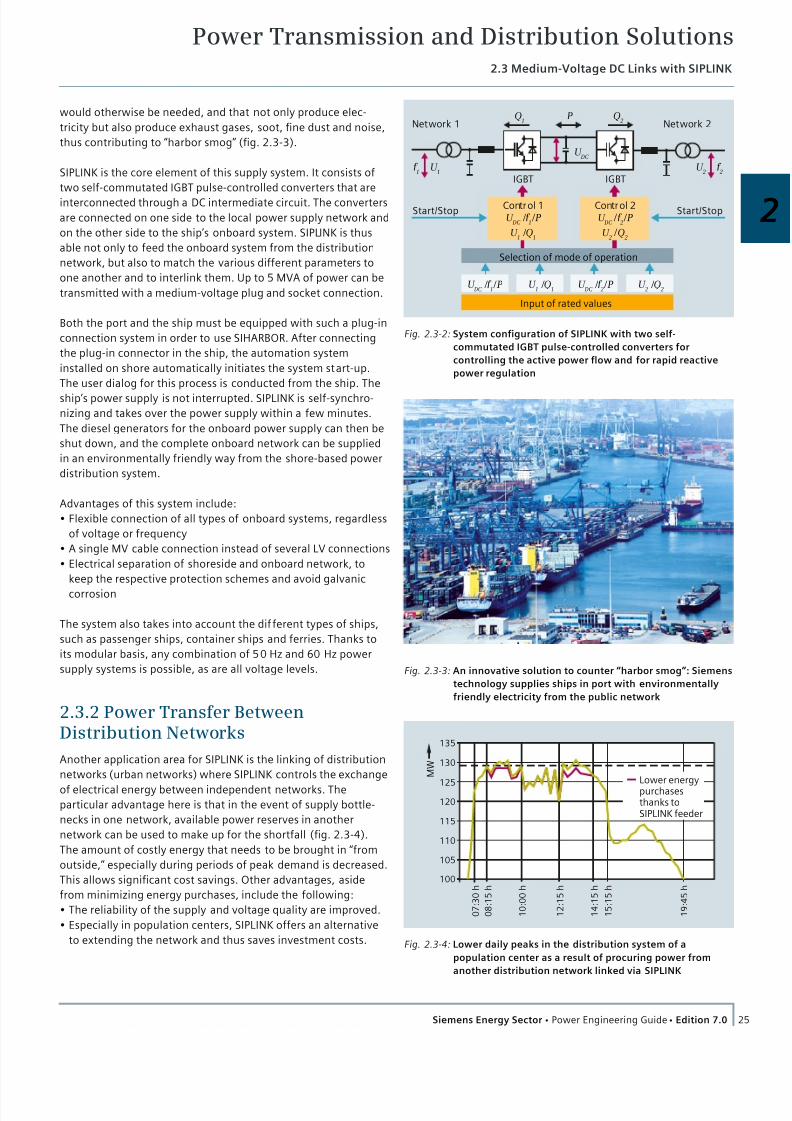
Fig. 2.3-1: SIPLINK with opened cabinet doors
Connection of ships berthed in port to the more environment-
friendly shoreside power supply system (SIHARBOR shore-to-
ship connection)
Energy transfer between different distribution networks (urban
networks) through interconnected operation
Increasing the availability and voltage quality of industrial
networks
2.3.1 Shore-to-Ship Connection
Cost pressure and increasingly stringent environmental regula-
tions are forcing many ports to supply ships in port with elec-
trical power from an onshore source. To address this need,
Siemens has developed SIHARBOR, a shore-to-ship connection
system that meets the requirements of port operators, shipping
companies, dockyards and power supply companies. Thanks to
SIHARBOR, ships can shut down their diesel generating sets that
7/22/2019 Transmision y Distribucion Siemens
http://slidepdf.com/reader/full/transmision-y-distribucion-siemens 12/50
2
Power Transmission and Distribution Solutions2.3 Medium-Voltage DC Links with SIPLINK
25Siemens Energy Sector Power Engineering Guide Edition 7.0
would otherwise be needed, and that not only produce elec-
tricity but also produce exhaust gases, soot, fine dust and noise,
thus contributing to “harbor smog” (fig. 2.3-3).
SIPLINK is the core element of this supply system. It consists of
two self-commutated IGBT pulse-controlled converters that are
interconnected through a DC intermediate circuit. The converters
are connected on one side to the local power supply network and
on the other side to the ship’s onboard system. SIPLINK is thus
able not only to feed the onboard system from the distribution
network, but also to match the various different parameters to
one another and to interlink them. Up to 5 MVA of power can be
transmitted with a medium-voltage plug and socket connection.
Both the port and the ship must be equipped with such a plug-in
connection system in order to use SIHARBOR. After connecting
the plug-in connector in the ship, the automation system
installed on shore automatically initiates the system start-up.
The user dialog for this process is conducted from the ship. The
ship’s power supply is not interrupted. SIPLINK is self-synchro-
nizing and takes over the power supply within a few minutes.
The diesel generators for the onboard power supply can then be
shut down, and the complete onboard network can be supplied
in an environmentally friendly way from the shore-based power
distribution system.
Advantages of this system include:
Flexible connection of all types of onboard systems, regardless
of voltage or frequency
A single MV cable connection instead of several LV connections
Electrical separation of shoreside and onboard network, to
keep the respective protection schemes and avoid galvanic
corrosion
The system also takes into account the dif ferent types of ships,
such as passenger ships, container ships and ferries. Thanks to
its modular basis, any combination of 50 Hz and 60 Hz power
supply systems is possible, as are all voltage levels.
2.3.2 Power Transfer BetweenDistribution Networks
Another application area for SIPLINK is the linking of distribution
networks (urban networks) where SIPLINK controls the exchange
of electrical energy between independent networks. The
particular advantage here is that in the event of supply bottle-
necks in one network, available power reserves in another
network can be used to make up for the shortfall (fig. 2.3-4).
The amount of costly energy that needs to be brought in “from
outside,” especially during periods of peak demand is decreased.
This allows significant cost savings. Other advantages, aside
from minimizing energy purchases, include the following:
The reliability of the supply and voltage quality are improved.
Especially in population centers, SIPLINK offers an alternative
to extending the network and thus saves investment costs.
Selection of mode of operation
Input of rated values
U DC
/ f 1 / P U
DC / f
2 / PU
1 / Q
1U
2 / Q
2
Control 1U
DC / f
1 / P
U 1 / Q
1
Control 2U
DC / f
2 / P
U 2 / Q
2
Start/StopStart/Stop
IGBT IGBT
Network 1 Network 2
U DC
P Q2
U 2
f 2
Q1
U 1
f 1
Fig. 2.3-2: System configuration of SIPLINK with two self-
commutated IGBT pulse-controlled converters for
controlling the active power flow and for rapid reactive
power regulation
Fig. 2.3-3: An innovative solution to counter “harbor smog”: Siemens
technology supplies ships in port with environmentally
friendly electricity from the public network
100
105
110
115
120
125
130
135
0 7 : 3 0 h
M W
0 8 : 1 5 h
1 0 : 0 0 h
1 2 : 1 5 h
1 4 : 1 5 h
1 5 : 1 5 h
1 9 : 4 5 h
Lower energypurchasesthanks toSIPLINK feeder
Fig. 2.3-4: Lower daily peaks in the distribution system of a
population center as a result of procuring power from
another distribution network linked via SIPLINK

7/22/2019 Transmision y Distribucion Siemens
http://slidepdf.com/reader/full/transmision-y-distribucion-siemens 13/50
Power Transmission and Distribution Solutions2.3 Medium-Voltage DC Links with SIPLINK
26 Siemens Energy Sector Power Engineering Guide Edition 7.0
2.3.3 High Availability of IndustrialNetworks
SIPLINK can also provide a reliable power supply to complex
plants and equipment, for example, in the oil and gas industry or
chemical industry.
SIPLINK provides unlimited options for switching electricity
between two or more networks at a medium-voltage level
exactly according to the individual requirements in the particular
network. This capability ensures improved supply reliability and
better voltage quality at the distribution level. The protection
afforded acts in both directions. Sensitive loads are protected
against “unclean” networks, and conversely, networks are pro-
tected against problematical consumers. Power generation costs
can also be reduced substantially through intelligent resource
management, thanks to SIPLINK. It is possible under cer tain
circumstances to avoid using additional diesel generators to
cover peak loads if less power is needed in another subnetwork
at that particular moment. Using SIPLINK cuts costs and reduces
pollution of the environment.
A high-availability power supply is essential for certain industrial
processes. In such cases, two independent incoming feeders can
jointly supply one load (Y-circuit). If one of these feeders fai ls,
the second takes over without interruption so that the change-
over is not noticeable at the consumer load (fig. 2.3-5). It is also
possible to divide the load between the two feeders in any
desired ratio, thus balancing the two feeders.
The SIPLINK Multi Feed configuration is specially suitable for
industrial processes where a high-availability power supply is
needed but very short interruptions in the millisecond range are
permissible (no voltage dips > 70 ms allowed) (fig. 2.3-6). In the
case of a short circuit or other fault in one of the power feeding
busbars, SIPLINK seamlessly takes over the power supply. SIP-
LINK is short-circuit-proof and feeds its rated power to short
circuit. At the same time, an OPEN command is sent to the
normal feeding switch on the busbar. As soon as the contacts of
the switch are opened (about 50 ms), the voltage on the busbar
increases immediately to the rated voltage (fig. 2.3-7). The Multi
Feed configuration is simpler in design than the Y-circuit and is
used where short voltage dips are acceptable.
150 kV150 kV 150 kV
35 kV35 kV35 kV
6 kV 6 kV 6 kV 6 kV
Independent busbars
Safe busbars
Fig. 2.3-6: With the SIPLINK Multi Feed circuit arrangement, each
of the safe busbars is connected simultaneously to three
busbars and an independent feeder
No production loss
Process still in operation
Short circuitin feeding system
Opening timeof faulty feeder
SIPLINK feeds in power needed
Voltagerecovery by
second feeder
Time
Time torestore process
Fig. 2.3-7: Voltage curve on the busbar in the case of a short circuit
in the feeding system with support by SIPLINK
SIMATIC S7
15 MVA
7UT
7UT
OP
15 MVA
15 MVA
7UT
M
~=
~~
~
==
=
M
M
E n e r g y fl
o wE n e r g y fl o w
Auxiliaries 3 , 400V
Pre-charge
Busbar 2:3 , 6 kV
2x7.5 MVA
1.1/6 kV
2x7.5 MVA
6/1.1 kV
Safe busbar:3 , 6 kV
~
~
~Busbar 1:3 , 6 kV~
2x7.5 MVA
6/1.1 kV
Fig. 2.3-5: With the fault-tolerant energy supply, the safe busbar
(or consumer) is connected simultaneously to two
feeding busbars

7/22/2019 Transmision y Distribucion Siemens
http://slidepdf.com/reader/full/transmision-y-distribucion-siemens 14/50
Power Transmission and Distribution Solutions
27Siemens Energy Sector Power Engineering Guide Edition 7.0
2
2.4 Flexible AC TransmissionSystems
Flexible AC Transmission Systems (FACTS) have been evolving to
a mature technology with high power ratings. The technology,
proven in numerous applications worldwide, became a first-rate,
highly reliable one. FACTS, based on power electronics, have
been developed to improve the performance of weak AC systems
and to make long distance AC transmission feasible and are an
essential part of smart grid and super grid developments (refer
to chapter 1).
FACTS can also help solve technical problems in the interconnected
power systems. FACTS are available in parallel connection:
Static Var Compensator (SVC)
Static Synchronous Compensator (STATCOM)
or in series connection:
Fixed Series Compensation (FSC)
Thyristor Controlled/Protected Series Compensation (TCSC/TPSC)
2.4.1 Parallel Compensation
Parallel compensation is defined as any type of reactive power
compensation employing either switched or controlled units that
are connected in parallel to the transmission network at a power
system node.
Mechanically Switched Capacitors/Reactors (MSC/MSR)
Mechanically switched devices are the most economical reactive
power compensation devices (fig. 2.4-1a).
Mechanically switched capacitors are a simple but low-speed
solution for voltage control and network stabilization under
heavy load conditions. Their utilization has almost no effect on
Fig. 2.4-1a: Mechanically switched capacitors (MSC) and mechanically switched reactors (MSR) connected to the transmission system
Fig. 2.4-1b: Static Var Compensator (SVC) with three branches (TCR, TSC, filter) and coupling transformer
Fig. 2.4-1c: SVC PLUS connected to the transmission system
MSC (DN)/MSR(DN = Damping network)
SVC
Parallel compensation
a) b) c)
52 < kV < 1,00050 < MVAr < 500
1
1 Switchgear 2 Capacitor 3 Reactor 4 Thyristor valve(s) 5 Transformer 6 IGBT valves 7 DC capacitors
1
2
2
3 33
2
3
55
4
6
7
52 < kV < 80050 < MVAr < 800
SVC PLUS
~8 < kV < 800±25 < MVAr < ±100 (and more)
the short-circuit power but it increases the voltage at the point
of connection.
Mechanically switched reactors have exactly the opposite
effect and are therefore preferable for achieving stabilization
under low load conditions.
An advanced form of mechanically switched capacitor is the
MSCDN. This device is an MSC with an additional damping
circuit for avoidance of system resonances.
Static Var Compensator (SVC)
Static Var Compensators are a fast and reliable means of control-
ling voltage on transmission lines and system nodes (fig. 2.4-1b,
fig. 2.4-2). The reactive power is changed by switching or con-
trolling reactive power elements connected to the secondary
side of the transformer. Each capacitor bank is switched ON and
Fig. 2.4-2: Static Var Compensator (SVC) installation

7/22/2019 Transmision y Distribucion Siemens
http://slidepdf.com/reader/full/transmision-y-distribucion-siemens 15/50
Power Transmission and Distribution Solutions2.4 Flexible AC Transmission Systems
28 Siemens Energy Sector Power Engineering Guide Edition 7.0
OFF by thyristor valves (TSC). Reactors can be either switched
(TSR) or controlled (TCR) by thyristor valves.
When system voltage is low, the SVC supplies capacitive reactive
power and rises the network voltage. When system voltage is
high, the SVC generates inductive reactive power and reduces
the system voltage.
Static Var Compensators perform the following tasks:
Improvement in voltage quality
Dynamic reactive power control
Increase in system stability
Damping of power oscillations
Increase in power transfer capability
Unbalance control (option)
The design and configuration of an SVC, including the size of the
installation, operating conditions and losses, depend on the
system conditions (weak or strong), the system configuration
(meshed or radial) and the tasks to be performed.
SVC PLUS – new generation of STATCOM
SVC PLUS is an advanced STATCOM which uses Voltage-Sourced
Converter (VSC) technology based on Modular Multilevel
Converter (MMC) design.
The MMC provides a nearly ideal sinusoidal-shaped waveform
on the AC side. Therefore, there is only little – if any – need for
high-frequency filtering and no need for low order harmonic
filtering.
MMC allows for low switching frequencies, which reduces
system losses.
SVC PLUS uses robust, proven standard components, such as
typical AC power transformers, reactors and switchgear.
The footprint of an SVC PLUS installation is up to 50 % smaller
than that of a conventional SVC installation of the same rating.
Applications
SVC PLUS fulfills the same task as conventional SVCs. Due to the
advanced technology, SVC PLUS is the preferred solution for grid
access solutions (e. g., wind parks).
Modular system design
The modular SVC PLUS is equipped with industrial class IGBT
(Insulated Gate Bipolar Transistors) power modules and DC
capacitors.
A very high level of system availability, thanks to theredundancy of power modules.
Standard WinCC and SIMATIC TDC control and protection
hardware and software are fully proven in practice in a wide
range of applications worldwide.
Portfolio
Standardized configurations are available: ± 25, ± 35, and ± 50
MVAr as containerized solutions. Up to four of these units can
be configured as a fully parallel operating system.
Easily expendable and relocatable
Open rack modular system configuration enables
transformerless grid connection up to 36 kV and ± 100 MVAr.
For higher system voltages, standard AC transformers are used.
Hybrid solutions with mechanically switched capacitors (MSC)
or reactors (MSR) are available.
Fig. 2.4-3: Two SVC PLUS units in New Zealand
Fig. 2.4-4: SVC PLUS containerized solution
8
11
14
36
800
S y s t e m v
o l t a g e
( k V )
Rective power (MVAr)
±25 ±35 ±50 ±100 ±200 ±400
SVC "Classic"
2 × SVC PLUS® CSVC "Classic"
4 × SVC PLUS® LSVC "Classic"
SVC PLUS® S
4 × SVC PLUS® L
2 × SVC PLUS® CSVC "Classic"
2 × SVC PLUS® C
SVC PLUS® M
SVC PLUS® L
SVC PLUS® S, M, L, C
SVC PLUS® C
Fig. 2.4-5: SVC PLUS portfolio

7/22/2019 Transmision y Distribucion Siemens
http://slidepdf.com/reader/full/transmision-y-distribucion-siemens 16/50
Power Transmission and Distribution Solutions2.4 Flexible AC Transmission Systems
29Siemens Energy Sector Power Engineering Guide Edition 7.0
2
Fig. 2.4-6: View of a TCSC system
2.4.2 Series Compensation
Series compensation is defined as insertion of reactive power
elements into transmission lines. The most common application
is the fixed series capacitor (FSC). Thyristor-valve controlled
systems (TCSC) and thyristor-valve protected systems (TPSC) may
also be installed.
Fixed Series Capacitor (FSC)
The simplest and most cost-effective type of series compensa-
tion is provided by FSCs. FSCs comprise the actual capacitor
banks, and for protection purposes, parallel arresters (metal-
oxide varistors, MOVs), spark gaps and a bypass switch for
isolation purposes (fig. 2.4-7a).
Fixed series compensation provides the following benefits:
Increase in transmission capacity
Reduction in transmission angle
Thyristor-Controlled Series Capacitor (TCSC)
Reactive power compensation by means of TCSCs can be
adapted to a wide range of operating conditions. It is also
possible to control the current and thus the load flow in parallel
transmission lines, which simultaneously improves system
stability. Another important application for TCSC is power oscilla-
tion damping.
Additional benefits of thyristor-controlled series compensation:
Damping of power oscillations (POD)
Load flow control
Increase in system stability
Thyristor-Protected Series Capacitor (TPSC)
Fig. 2.4-7a: Fixed series compensation (FSC) connected to the network
Fig. 2.4-7b: Thyristor-controlled series capacitor (TCSC) connected to the network
Fig. 2.4-7c: Thyristor-protected series capacitor (TPSC) connected to the network
FSC TCSC
Series compensation
a) b) c)
3 4
220 < kV < 800200 < MVAr < 800
6
5
2 2
52 < kV < 80050 < MVAr < 800
TPSC
3 4
L im
2
220 < kV < 800100 < MVAr < 800
1 Switchgear 2 Capacitor 3 Reactor 4 Thyristor valve(s) 5 Arrester 6 Circuit-breaker
When high power thyristors are used, there is no need to install
conventional spark gaps or surge arresters. Due to the very short
cooling-down times of the special thyristor valves, TPSCs can be
quickly returned to service after a line fault, allowing the trans-
mission lines to be utilized to their maximum capacity. TPSCs are
the first choice whenever transmission lines must be returned to
maximum carrying capacity as quickly as possible after a failure
(fig. 2.4-7c).
For further information:
http://www.siemens.com/energy/facts
7/22/2019 Transmision y Distribucion Siemens
http://slidepdf.com/reader/full/transmision-y-distribucion-siemens 17/50
Power Transmission and Distribution Solutions
30 Siemens Energy Sector Power Engineering Guide Edition 7.0
2.5 Power Transmission Lines
2.5.1 Gas-Insulated Transmission Lines
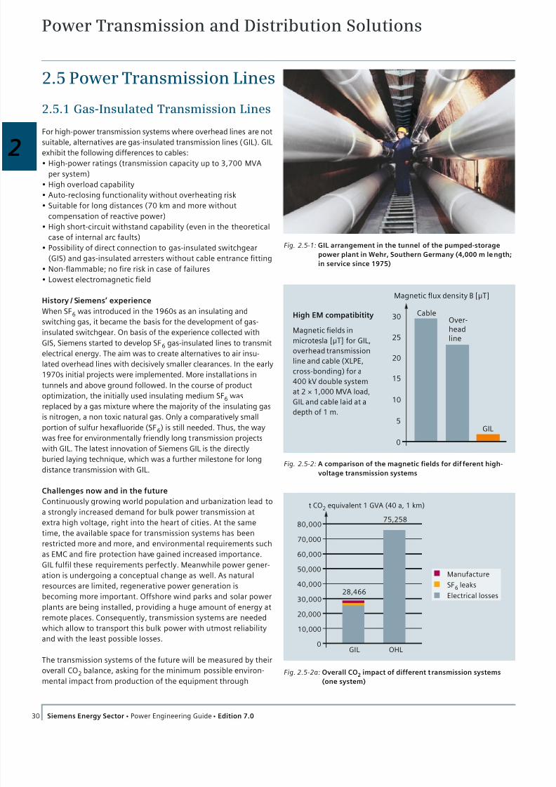
Fig. 2.5-1: GIL arrangement in the tunnel of the pumped-storage
power plant in Wehr, Southern Germany (4,000 m length;
in service since 1975)
For high-power transmission systems where overhead lines are not
suitable, alternatives are gas-insulated transmission lines (GIL). GIL
exhibit the following differences to cables:
High-power ratings (transmission capacity up to 3,700 MVA
per system)
High overload capability
Auto-reclosing functionality without overheating risk
Suitable for long distances (70 km and more without
compensation of reactive power)
High short-circuit withstand capability (even in the theoretical
case of internal arc faults)
Possibility of direct connection to gas-insulated switchgear
(GIS) and gas-insulated arresters without cable entrance fitting
Non-flammable; no fire risk in case of failures
Lowest electromagnetic field
History / Siemens’ experience
When SF6 was introduced in the 1960s as an insulating and
switching gas, it became the basis for the development of gas-
insulated switchgear. On basis of the experience collected with
GIS, Siemens started to develop SF6 gas-insulated lines to transmit
electrical energy. The aim was to create alternatives to air insu-
lated overhead lines with decisively smaller clearances. In the early
1970s initial projects were implemented. More installations in
tunnels and above ground followed. In the course of product
optimization, the initially used insulating medium SF6 was
replaced by a gas mixture where the majority of the insulating gas
is nitrogen, a non toxic natural gas. Only a comparatively small
portion of sulfur hexafluoride (SF6) is still needed. Thus, the way
was free for environmentally friendly long transmission projects
with GIL. The latest innovation of Siemens GIL is the directly
buried laying technique, which was a further milestone for long
distance transmission with GIL.
Challenges now and in the future
Continuously growing world population and urbanization lead to
a strongly increased demand for bulk power transmission at
extra high voltage, right into the heart of cities. At the same
time, the available space for transmission systems has been
restricted more and more, and environmental requirements such
as EMC and fire protection have gained increased importance.
GIL fulfil these requirements perfectly. Meanwhile power gener-
ation is undergoing a conceptual change as well. As natural
resources are limited, regenerative power generation is
becoming more important. Offshore wind parks and solar power
plants are being installed, providing a huge amount of energy at
remote places. Consequently, transmission systems are needed
which allow to transport this bulk power with utmost reliability
and with the least possible losses.
The transmission systems of the future will be measured by their
overall CO2 balance, asking for the minimum possible environ-
mental impact from production of the equipment through
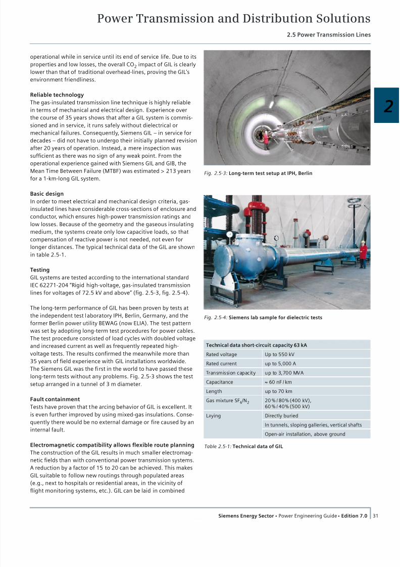
Over-headline
GIL
Cable30
Magnetic flux density B [µT]
25
20
15
10
5
0
High EM compatibitity
Magnetic fields in
microtesla [µT] for GIL,
overhead transmission
line and cable (XLPE,
cross-bonding) for a
400 kV double system
at 2 × 1,000 MVA load,
GIL and cable laid at a
depth of 1 m.
Fig. 2.5-2: A comparison of the magnetic fields for dif ferent high-
voltage transmission systems
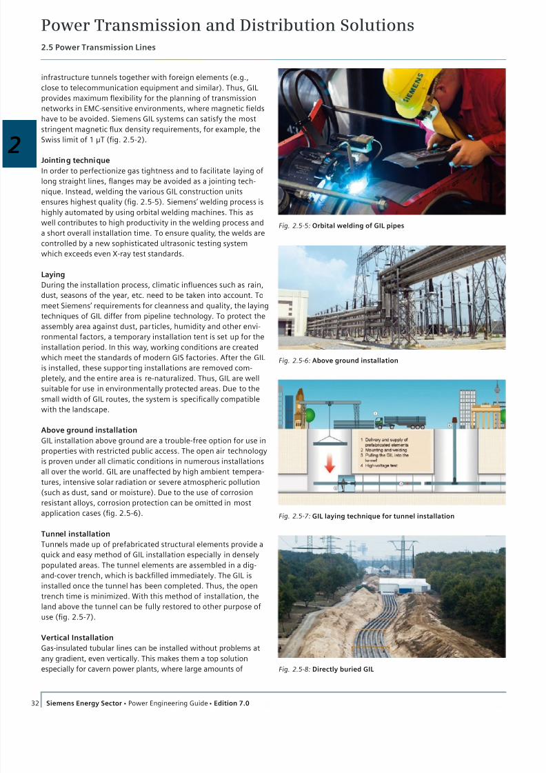
75,258
28,466
80,000
t CO2 equivalent 1 GVA (40 a, 1 km)
70,000
60,000
50,000
40,000
30,000
20,000
10,000
0GIL OHL
Manufacture
SF6 leaks
Electrical losses
Fig. 2.5-2a: Overall CO2 impact of different t ransmission systems
(one system)
7/22/2019 Transmision y Distribucion Siemens
http://slidepdf.com/reader/full/transmision-y-distribucion-siemens 18/50
Power Transmission and Distribution Solutions2.5 Power Transmission Lines
31Siemens Energy Sector Power Engineering Guide Edition 7.0
2
operational while in service until its end of service life. Due to its
properties and low losses, the overall CO2 impact of GIL is clearly
lower than that of traditional overhead-lines, proving the GIL’s
environment friendliness.
Reliable technology
The gas-insulated transmission line technique is highly reliable
in terms of mechanical and electrical design. Experience over
the course of 35 years shows that after a GIL system is commis-
sioned and in service, it runs safely without dielectrical or
mechanical failures. Consequently, Siemens GIL – in service for
decades – did not have to undergo their initially planned revision
after 20 years of operation. Instead, a mere inspection was
sufficient as there was no sign of any weak point. From the
operational experience gained with Siemens GIL and GIB, the
Mean Time Between Failure (MTBF) was estimated > 213 years
for a 1-km-long GIL system.
Basic design
In order to meet electrical and mechanical design criteria, gas-
insulated lines have considerable cross-sections of enclosure and
conductor, which ensures high-power transmission ratings and
low losses. Because of the geometry and the gaseous insulating
medium, the systems create only low capacitive loads, so that
compensation of reactive power is not needed, not even for
longer distances. The typical technical data of the GIL are shown
in table 2.5-1.
Testing
GIL systems are tested according to the international standard
IEC 62271-204 “Rigid high-voltage, gas-insulated transmission
lines for voltages of 72.5 kV and above” (fig. 2.5-3, fig. 2.5-4).
The long-term performance of GIL has been proven by tests at
the independent test laboratory IPH, Berlin, Germany, and the
former Berlin power utility BEWAG (now ELIA). The test pattern
was set by adopting long-term test procedures for power cables.
The test procedure consisted of load cycles with doubled voltage
and increased current as well as frequently repeated high-
voltage tests. The results confirmed the meanwhile more than
35 years of field experience with GIL installations worldwide.
The Siemens GIL was the first in the world to have passed these
long-term tests without any problems. Fig. 2.5-3 shows the test
setup arranged in a tunnel of 3 m diameter.
Fault containmentTests have proven that the arcing behavior of GIL is excellent. It
is even further improved by using mixed-gas insulations. Conse-
quently there would be no external damage or fire caused by an
internal fault.
Electromagnetic compatibility allows flexible route planning
The construction of the GIL results in much smaller electromag-
netic fields than with conventional power transmission systems.
A reduction by a factor of 15 to 20 can be achieved. This makes
GIL suitable to follow new routings through populated areas
(e.g., next to hospitals or residential areas, in the vicinity of
flight monitoring systems, etc.). GIL can be laid in combined
Table 2.5-1: Technical data of GIL
Technical data short-circuit capacity 63 kA
Rated voltage Up to 550 kV
Rated current up to 5,000 A
Transmission capacity up to 3,700 MVA
Capacitance ≈ 60 nF / km
Length up to 70 km
Gas mixture SF6/N2 20 % / 80 % (400 kV),60 % / 40 % (500 kV)
Laying Directly buried
In tunnels, sloping galleries, vertical shafts
Open-air installation, above ground
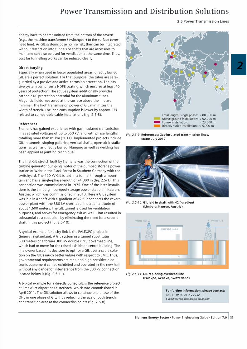
Fig. 2.5-3: Long-term test setup at IPH, Berlin
Fig. 2.5-4: Siemens lab sample for dielectric tests
7/22/2019 Transmision y Distribucion Siemens
http://slidepdf.com/reader/full/transmision-y-distribucion-siemens 19/50
Power Transmission and Distribution Solutions2.5 Power Transmission Lines
32 Siemens Energy Sector Power Engineering Guide Edition 7.0
infrastructure tunnels together with foreign elements (e.g.,
close to telecommunication equipment and similar). Thus, GIL
provides maximum flexibility for the planning of transmission
networks in EMC-sensitive environments, where magnetic fields
have to be avoided. Siemens GIL systems can satisfy the most
stringent magnetic flux density requirements, for example, the
Swiss limit of 1 μT (fig. 2.5-2).
Jointing technique
In order to perfectionize gas tightness and to facilitate laying of
long straight lines, flanges may be avoided as a jointing tech-
nique. Instead, welding the various GIL construction units
ensures highest quality (fig. 2.5-5). Siemens’ welding process is
highly automated by using orbital welding machines. This as
well contributes to high productivity in the welding process and
a short overall installation time. To ensure quality, the welds are
controlled by a new sophisticated ultrasonic testing system
which exceeds even X-ray test standards.
Laying
During the installation process, climatic influences such as rain,
dust, seasons of the year, etc. need to be taken into account. To
meet Siemens’ requirements for cleanness and quality, the laying
techniques of GIL differ from pipeline technology. To protect the
assembly area against dust, particles, humidity and other envi-
ronmental factors, a temporary installation tent is set up for the
installation period. In this way, working conditions are created
which meet the standards of modern GIS factories. After the GIL
is installed, these supporting installations are removed com-
pletely, and the entire area is re-naturalized. Thus, GIL are well
suitable for use in environmentally protected areas. Due to the
small width of GIL routes, the system is specifically compatible
with the landscape.
Above ground installation
GIL installation above ground are a trouble-free option for use in
properties with restricted public access. The open air technology
is proven under all climatic conditions in numerous installations
all over the world. GIL are unaffected by high ambient tempera-
tures, intensive solar radiation or severe atmospheric pollution
(such as dust, sand or moisture). Due to the use of corrosion
resistant alloys, corrosion protection can be omitted in most
application cases (fig. 2.5-6).
Tunnel installation
Tunnels made up of prefabricated structural elements provide aquick and easy method of GIL installation especially in densely
populated areas. The tunnel elements are assembled in a dig-
and-cover trench, which is backfilled immediately. The GIL is
installed once the tunnel has been completed. Thus, the open
trench time is minimized. With this method of installation, the
land above the tunnel can be fully restored to other purpose of
use (fig. 2.5-7).
Vertical Installation
Gas-insulated tubular lines can be installed without problems at
any gradient, even vertically. This makes them a top solution
especially for cavern power plants, where large amounts of
Fig. 2.5-7: GIL laying technique for tunnel installation
Fig. 2.5-5: Orbital welding of GIL pipes
Fig. 2.5-6: Above ground installation
Fig. 2.5-8: Directly buried GIL
7/22/2019 Transmision y Distribucion Siemens
http://slidepdf.com/reader/full/transmision-y-distribucion-siemens 20/50
Power Transmission and Distribution Solutions2.5 Power Transmission Lines
33Siemens Energy Sector Power Engineering Guide Edition 7.0
2
energy have to be transmitted from the bottom of the cavern
(e.g., the machine transformer / switchgear) to the surface (over-
head line). As GIL systems pose no fire risk, they can be integrated
without restriction into tunnels or shafts that are accessible to
man, and can also be used for ventilation at the same time. Thus,
cost for tunnelling works can be reduced clearly.
Direct burying
Especially when used in lesser populated areas, directly buried
GIL are a perfect solution. For that purpose, the tubes are safe-
guarded by a passive and active corrosion protection. The pas-
sive system comprises a HDPE coating which ensures at least 40
years of protection. The active system additionally provides
cathodic DC protection potential for the aluminum tubes.
Magentic fields measured at the surface above the line are
minimal. The high transmission power of GIL minimizes the
width of trench. The land consumption is lower by approx. 1/3
related to comparable cable installations (fig. 2.5-8).
References
Siemens has gained experience with gas-insulated transmission
lines at rated voltages of up to 550 kV, and with phase lengths
totalling more than 85 km (2011). Implemented projects include
GIL in tunnels, sloping galleries, vertical shafts, open-air installa-
tions, as well as directly buried. Flanging as well as welding has
been applied as jointing technique.
The first GIL stretch built by Siemens was the connection of the
turbine generator pumping motor of the pumped storage power
station of Wehr in the Black Forest in Southern Germany with the
switchyard. The 420 kV GIL is laid in a tunnel through a moun-
tain and has a single-phase length of ~4,000 m (fig. 2.5-1). This
connection was commissioned in 1975. One of the later installa-
tions is the Limberg II pumped-storage power station in Kaprun,
Austria, which was commissioned in 2010. Here a GIL system
was laid in a shaft with a gradient of 42 °. It connects the cavern
power plant with the 380 kV overhead line at an altitude of
about 1,600 meters. The GIL tunnel is used for ventilation
purposes, and serves for emergency exit as well. That resulted in
substantial cost reduction by eliminating the need for a second
shaft in this project (fig. 2.5-10).
A typical example for a city link is the PALEXPO project in
Geneva, Switzerland. A GIL system in a tunnel substitutes
500 meters of a former 300 kV double circuit overhead line,
which had to move for the raised exhibition centre building. Theline owner based his decision to opt for a GIL over a cable solu-
tion on the GIL’s much better values with respect to EMC. Thus,
governmental requirements are met, and high sensitive elec-
tronic equipment can be exhibited and operated in the new hall
without any danger of interference from the 300 kV connection
located below it (fig. 2.5-11).
A typical example for a directly buried GIL is the reference project
at Frankfurt Airport at Kelsterbach, which was commissioned in
April 2011. The GIL solution allows to continue one phase of the
OHL in one phase of GIL, thus reducing the size of both trench
and transition area at the connection points (fig. 2.5-8).
Total length, single phase: > 80,000 mAbove ground installation: > 52,000 m
Tunnel installation: > 23,000 mDirectly buried installation: > 5,000 m
Fig. 2.5-9: References: Gas-insulated transmission lines,
status July 2010
Fig. 2.5-11: GIL replacing overhead line
(Palexpo, Geneva, Switzerland)
Fig. 2.5-10: GIL laid in shaft with 42 ° gradient
(Limberg, Kaprun, Austria)
For further information, please contact:
Tel.: ++ 49 91 31-7- 2 72 62
E-mail: [email protected]

7/22/2019 Transmision y Distribucion Siemens
http://slidepdf.com/reader/full/transmision-y-distribucion-siemens 21/50
Power Transmission and Distribution Solutions2.5 Power Transmission Lines
34 Siemens Energy Sector Power Engineering Guide Edition 7.0
2.5.2 Overhead Lines
Since the very beginning of electric power generation, overhead
transmission lines (OHL) have constituted the most important
component for transmission and distribution of electric power.
The portion of overhead transmission lines within a transmission
and distribution network depends on the voltage level as well as
on local conditions and practice. In densely populated areas like
Central Europe, underground cables prevail in the distribution
sector, and overhead power lines in the high-voltage transmis-
sion sector. In other parts of the world, for example, in North
America, overhead lines are often also used for distribution
purposes within cities. Siemens has planned, designed and
erected overhead power lines for all important voltage levels in
many parts of the world.
Selection of line voltage
For the distribution and transmission of electric power,
standardized voltages according to IEC 60038 are used world-
wide. For 3-phase AC applications, three voltage levels prevail:
Low voltage (up to 1 kV AC)
Medium voltage (between 1 kV and 36 kV AC)
High voltage (between 52 kV and 765 kV AC) and higher
Low-voltage lines serve households and small business con-
sumers. Lines on the medium-voltage level supply small settle-
ments, individual industrial plants and large consumers; the
transmission capacity is typically less than 10 MVA per circuit.
The high-voltage circuits up to 145 kV serve for subtransmission
of the electric power regionally, and feed the medium-voltage
network. This level is often chosen to support the medium-
voltage level even if the electric power is below 10 MVA. More-
over, some of these high-voltage lines also transmit the electric
power from medium-sized generating stations, such as hydro
plants on small and medium rivers, and supply large-scale
consumers, such as sizable industrial plants or steel mills. They
constitute the connection between the interconnected high-
voltage grid and the local distribution networks. The bandwidth
of electrical power transported corresponds to the broad range
of utilization, but rarely exceeds 100 MVA per circuit, while the
surge impedance load is 35 MVA (approximately).
In Central Europe, 245 kV lines were used for interconnection of
power supply systems before the 420 kV level was introduced for
this purpose. Long-distance transmission, for example, between
the hydro power plants in the Alps and consumers, was done by245 kV lines. Nowadays, the importance of 245 kV lines is
decreasing due to the existence of the 420 kV transmission
network. The 420 kV level represents the highest operation
voltage used for AC transmission in Central Europe. It typically
interconnects the power supply systems and transmits the
energy over long distances. Some 420 kV lines connect the
national grids of the individual European countries enabling
interconnected network operation (UCTE = Union for the Co-
ordination of Transmission of Electricity) throughout Europe.
Large power plants such as nuclear stations feed directly into the
420 kV network. The thermal capacity of the 420 kV circuits may
reach 2,000 MVA, with a surge impedance load of approximately
600 MVA and a transmission capacity up to 1,200 MVA.
Overhead power lines with voltages higher than 420 kV AC will
be required in the future to economically transmit bulk electric
power over long distances, a task typically arising when uti-
lizing hydro, wind and solar energy potentials far away from
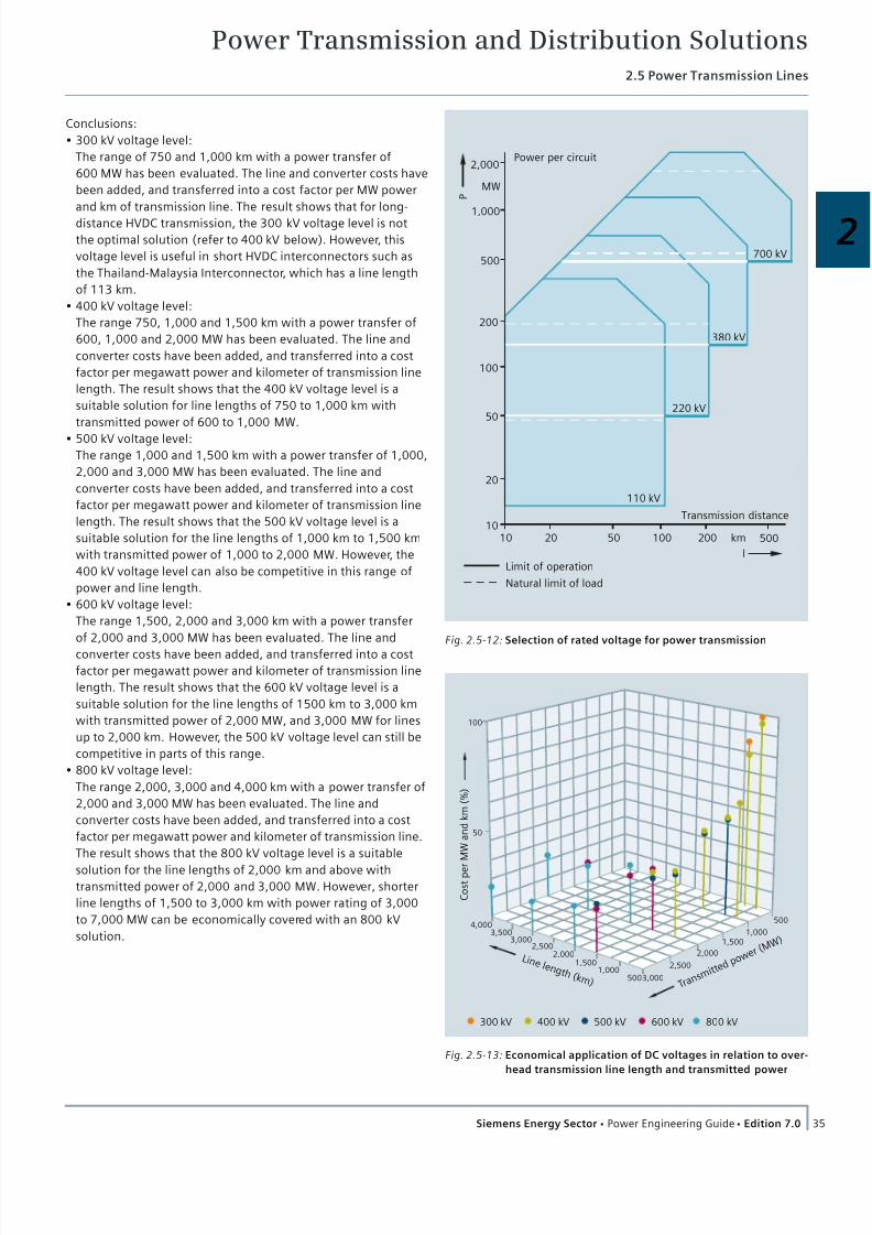
consumer centers. Fig. 2.5-12 depicts schematically the range
of application for the individual AC voltage levels based on the
distance of transmission and the power rating. The voltage
level has to be selected based on the task of the line within the
network or on the results of network planning. Siemens has
carried out such studies for power supply companies all over
the world.
High-voltage direct current
However, when considering bulk power transmission over long
distances, a more economical solution is the high-voltage direct
current (HVDC) technology. Siemens is in the position to offer
complete solutions for such interconnections, starting with
network studies and followed by the design, assistance in project
development and complete turnkey supply and construction of
such plants. For DC transmission no standard is currently avail-
able. The DC voltages vary from the voltage levels recommended
in the above-mentioned standardized voltages used for AC.
HVDC transmission is used for bulk power transmission and for
system interconnection. The line voltages applied for projects
worldwide vary between ± 300 kV, ± 400 kV, ± 500 kV, ± 600 kV
and recently (2007), ± 800 kV. The selection of the HVDC line
voltage is ruled by the following parameters:
Amount of power to be transferred
Length of the overhead power line
Permissible power losses
Economical conductor size
The advantages of DC transmission over AC transmission are:
A DC link allows power transfer between AC networks with
different frequencies or networks that cannot be synchronized.
Inductive and capacitive parameters do not limit the
transmission capacity or the maximum length of a DC
overhead transmission line.
The conductor cross-section can be more or less fully utilized
because there is no skin ef fect caused by the line frequency.
DC overhead power lines are much more economical to builtand require less right-of-way.
Economical considerations/evaluation of DC voltages
Fig. 2.5-13 shows the economical application of DC voltages in
relation to overhead transmission line length and transmitted
power. This graph must be seen as a general guideline. Any
project should be separately evaluated on a case-by-case basis.
The budgets established for this evaluation are based on 2007
figures.
7/22/2019 Transmision y Distribucion Siemens
http://slidepdf.com/reader/full/transmision-y-distribucion-siemens 22/50
Power Transmission and Distribution Solutions2.5 Power Transmission Lines
35Siemens Energy Sector Power Engineering Guide Edition 7.0
2
Conclusions:
300 kV voltage level:
The range of 750 and 1,000 km with a power transfer of
600 MW has been evaluated. The line and converter costs have
been added, and transferred into a cost factor per MW power
and km of transmission line. The result shows that for long-
distance HVDC transmission, the 300 kV voltage level is not
the optimal solution (refer to 400 kV below). However, this
voltage level is useful in short HVDC interconnectors such as
the Thailand-Malaysia Interconnector, which has a line length
of 113 km.
400 kV voltage level:
The range 750, 1,000 and 1,500 km with a power transfer of
600, 1,000 and 2,000 MW has been evaluated. The line and
converter costs have been added, and transferred into a cost
factor per megawatt power and kilometer of transmission line
length. The result shows that the 400 kV voltage level is a
suitable solution for line lengths of 750 to 1,000 km with
transmitted power of 600 to 1,000 MW.
500 kV voltage level:
The range 1,000 and 1,500 km with a power transfer of 1,000,
2,000 and 3,000 MW has been evaluated. The line and
converter costs have been added, and transferred into a cost
factor per megawatt power and kilometer of transmission line
length. The result shows that the 500 kV voltage level is a
suitable solution for the line lengths of 1,000 km to 1,500 km
with transmitted power of 1,000 to 2,000 MW. However, the
400 kV voltage level can also be competitive in this range of
power and line length.
600 kV voltage level:
The range 1,500, 2,000 and 3,000 km with a power transfer
of 2,000 and 3,000 MW has been evaluated. The line and
converter costs have been added, and transferred into a cost
factor per megawatt power and kilometer of transmission line
length. The result shows that the 600 kV voltage level is a
suitable solution for the line lengths of 1500 km to 3,000 km
with transmitted power of 2,000 MW, and 3,000 MW for lines
up to 2,000 km. However, the 500 kV voltage level can still be
competitive in parts of this range.
800 kV voltage level:
The range 2,000, 3,000 and 4,000 km with a power transfer of
2,000 and 3,000 MW has been evaluated. The line and
converter costs have been added, and transferred into a cost
factor per megawatt power and kilometer of transmission line.
The result shows that the 800 kV voltage level is a suitable
solution for the line lengths of 2,000 km and above with
transmitted power of 2,000 and 3,000 MW. However, shorter
line lengths of 1,500 to 3,000 km with power rating of 3,000
to 7,000 MW can be economically covered with an 800 kV
solution.
2,000
1,000
500
200
100
50
20
1010 20 50 100 200 500km
MW P
Power per circuit
110 kV
220 kV
380 kV
700 kV
Transmission distance
Limit of operation
Natural limit of load
l
Fig. 2.5-12: Selection of rated voltage for power transmission
100
50
4,0003,500
500
500
3,0001,000
1,000
1,500
1,500
2,000 2,0002,500
2,500
3,000
300 kV 400 kV
L i n e l e n g t h ( k m )
C o s t p e r
M W a
n d k m ( %
)
T r a n s m i
t t e d p o w
e r ( M W
)
500 kV 600 kV 800 kV
Fig. 2.5-13: Economical application of DC voltages in relation to over-
head transmission line length and transmitted power

7/22/2019 Transmision y Distribucion Siemens
http://slidepdf.com/reader/full/transmision-y-distribucion-siemens 23/50
Power Transmission and Distribution Solutions2.5 Power Transmission Lines
36 Siemens Energy Sector Power Engineering Guide Edition 7.0
Selection of conductors and earth wires
Conductors represent the most important component of an over-
head power line because they have to ensure economical and
reliable transmission and contribute considerably to the total
line costs. For many years, aluminum and its alloys have been
the prevailing conducting materials for power lines due to the
favorable price, the low weight and the necessity of certain
minimum cross-sections. However, aluminum is a very corrosive
metal. But a dense oxide layer is formed that stops further
corrosive attacks. Therefore, up to a cer tain level, aluminum
conductors are well-suited for areas in which corrosion is a
problem, for example, a maritime climate.
For aluminum conductors, there are a number of different
designs in use. All-aluminum conductors (AAC) have the highest
conductivity for a given cross-section; however, they possess
only a low mechanical strength, which limits their application to
short spans and low tensile forces. To increase the mechanical
strength, wires made of aluminum-magnesium-silicon alloys are
adopted. Their strength is approximately twice that of pure
aluminum. But single-material conductors like all-aluminum and
aluminum alloy conductors have shown susceptibility to eolian
vibrations. Compound conductors with a steel core, so-called
aluminum conductor, steel-reinforced (ACSR), avoid this disad-
vantage. The ratio between aluminum and steel ranges from
4.3:1 to 11:1. An aluminum-to-steel ratio of 6.0 or 7.7 provides
an economical solution. Conductors with a ratio of 4.3 should be
used for lines installed in regions with heavy wind and ice loads.
Conductors with a ratio higher than 7.7 provide higher conduc-
tivity. But because of lower conductor strength, the sags are
bigger, which requires higher towers.
Experience has shown that ACSR conductors, just like aluminum
and aluminum alloy conductors, provide the most economical
solution and offer a life span greater than 40 years. Conductors
are selected according to electrical, thermal, mechanical and
economic aspects. The electric resistance as a result of the con-
ducting material and its cross-section is the most important
feature affecting the voltage drop and the energy losses along the
line and, therefore, the transmission costs. The cross-section has
to be selected so that the permissible temperatures will not be
exceeded during normal operation as well as under short-circuit
condition. With increasing cross-section, the line costs increase,
while the costs for losses decrease. Depending on the length of
the line and the power to be transmitted, a cross-section can be
determined that results in the lowest transmission costs. The heat
balance of ohmic losses and solar radiation against convection
and radiation determines the conductor temperature. A current
density of 0.5 to 1.0 A/mm2 based on the aluminum cross-section
has proven to be an economical solution in most cases.
High-voltage results in correspondingly high-voltage gradients at
the conductor’s surface, and in corona-related effects such as
visible discharges, radio interference, audible noise and energy
losses. When selecting the conductors, the AC voltage gradient
has to be limited to values between 15 and 17 kV/cm. Since the
sound of the audible noise of DC lines is mainly caused at the
positive pole and this sound differs from those of AC lines, the
subjective feeling differs as well. Therefore, the maximum surface
voltage gradient of DC lines is higher than the gradient for AC
lines. A maximum value of 25 kV/cm is recommended. The line
voltage and the conductor diameter are one of the main factors
that influence the surface voltage gradient. In order to keep this
gradient below the limit value, the conductor can be divided into
subconductors. This results in an equivalent conductor diameter
that is bigger than the diameter of a single conductor with the
same cross-section. This aspect is important for lines with volt-
ages of 245 kV and above. Therefore, so-called bundle conduc-
tors are mainly adopted for extra-high-voltage lines. Table 2.5-2
shows typical conductor configurations for AC lines.
From a mechanical point of view, the conductors have to be
designed for everyday conditions and for maximum loads
exerted on the conductor by wind and ice. As a rough figure, an
everyday stress of approximately 20 % of the conductor rated
tensile stress can be adopted, resulting in a limited risk of con-
Table 2.5-2: Electric characteristics of AC overhead power lines (data refer to one circuit of a double-circuit line)
Rated voltage [kV] 20 110 220 380 700
Highest system voltage [kV] 24 123 245 420 765
Nominal cross-section [mm2] 50 120 150 300 435 bundle 2x240 bundle 4x240 bundle 2x560 bundle 4x560
Conductor diameter [mm] 9.6 15.5 17.1 24.5 28.8 2x21.9 4x21.9 2x32.2 4x32.2
Ampacity (at 80 °C conductor temperature) [A] 210 410 470 740 900 1,290 2,580 2,080 4,160Thermal capacity [MVA] 7 14 90 140 340 490 1,700 1,370 5,400
Resistance at 20 °C [Ω/km] 0.59 0.24 0.19 0.10 0.067 0.059 0.030 0.026 0.013
Reactance at 50 Hz [Ω/km] 0.39 0.34 0.41 0.38 0.4 0.32 0.26 0.27 0.28
Effective capacitance [nF/km] 9.7 11.2 9.3 10 9.5 11.5 14.4 13.8 13.1
Capacitance to earth [nF/km] 3.4 3.6 4.0 4.2 4.8 6.3 6.5 6.4 6.1
Charging power [kVA/km] 1.2 1.4 35 38 145 175 650 625 2,320
Earth-fault current [A/km] 0.04 0.04 0.25 0.25 0.58 0.76 1.35 1.32 2.48
Surge impedance [Ω] 360 310 375 350 365 300 240 250 260
Surge impedance load [MVA] – – 32 35 135 160 600 577 2,170
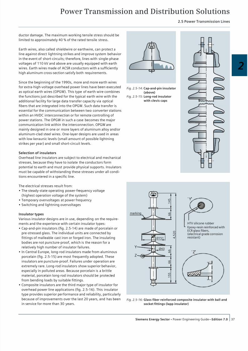
7/22/2019 Transmision y Distribucion Siemens
http://slidepdf.com/reader/full/transmision-y-distribucion-siemens 24/50
Power Transmission and Distribution Solutions2.5 Power Transmission Lines
37Siemens Energy Sector Power Engineering Guide Edition 7.0
2
ductor damage. The maximum working tensile stress should be
limited to approximately 40 % of the rated tensile stress.
Earth wires, also called shieldwire or earthwire, can protect a
line against direct lightning strikes and improve system behavior
in the event of short-circuits; therefore, lines with single-phase
voltages of 110 kV and above are usually equipped with earth
wires. Earth wires made of ACSR conductors with a sufficiently
high aluminum cross-section satisfy both requirements.
Since the beginning of the 1990s, more and more earth wires
for extra-high-voltage overhead power lines have been executed
as optical earth wires (OPGW). This type of earth wire combines
the functions just described for the typical earth wire with the
additional facility for large data transfer capacity via optical
fibers that are integrated into the OPGW. Such data transfer is
essential for the communication between two converter stations
within an HVDC interconnection or for remote controlling of
power stations. The OPGW in such a case becomes the major
communication link within the interconnection. OPGW are
mainly designed in one or more layers of aluminum alloy and/or
aluminum-clad steel wires. One-layer designs are used in areas
with low keraunic levels (small amount of possible lightning
strikes per year) and small short-circuit levels.
Selection of insulators
Overhead line insulators are subject to electrical and mechanical
stresses, because they have to isolate the conductors form
potential to earth and must provide physical supports. Insulators
must be capable of withstanding these stresses under all condi-
tions encountered in a specific line.
The electrical stresses result from:
The steady-state operating power-frequency voltage
(highest operation voltage of the system)
Temporary overvoltages at power frequency
Switching and lightning overvoltages
Insulator types
Various insulator designs are in use, depending on the require-
ments and the experience with certain insulator types:
Cap-and-pin insulators (fig. 2.5-14) are made of porcelain or
pre-stressed glass. The individual units are connected by
fittings of malleable cast iron or forged iron. The insulating
bodies are not puncture-proof, which is the reason for a
relatively high number of insulator failures. In Central Europe, long-rod insulators made from aluminous
porcelain (fig. 2.5-15) are most frequently adopted. These
insulators are puncture-proof. Failures under operation are
extremely rare. Long-rod insulators show superior behavior,
especially in polluted areas. Because porcelain is a brittle
material, porcelain long-rod insulators should be protected
from bending loads by suitable fittings.
Composite insulators are the third major type of insulator for
overhead power line applications (fig. 2.5-16). This insulator
type provides superior performance and reliability, particularly
because of improvements over the last 20 years, and has been
in service for more than 30 years.
Fig. 2.5-14: Cap-and-pin insulator
(above)
Fig. 2.5-15: Long-rod insulator
with clevis caps
HTV silicone rubber
Epoxy-resin reinforced withECR glass fibers,(electrical grade corrosionresistant)
Z
Y 1 4 5
4 , 5 2 0
6 6
Ø151
marking
6 6
6 6
1 5 5
Ø43 Y
Z
Fig. 2.5-16: Glass fiber reinforced composite insulator with ball and
socket fittings (lapp insulator)

7/22/2019 Transmision y Distribucion Siemens
http://slidepdf.com/reader/full/transmision-y-distribucion-siemens 25/50
Power Transmission and Distribution Solutions2.5 Power Transmission Lines
38 Siemens Energy Sector Power Engineering Guide Edition 7.0
The composite insulator is made of a glass fiber reinforced
epoxy rod. The glass fibers applied are ECR glass fibers that are
resistant to brittle fracture (ECR = electrical grade corrosion
resistant glass fibers). In order to avoid brittle fracture, the glass
fiber rod must additionally be sealed very carefully and durably
against moisture. This is done by application of silicone rubber.
Nowadays, high temperature vulcanized (HTV) silicone is used.
The silicone rubber has two functions within this insulator type:
Sealing the glass fiber rod
Molding into insulator sheds to establish the required insulation
Metal fittings are compressed onto the glass fiber rod at both
ends of the insulator, either with a ball socket or clevis connec-
tion fitting. Since the 1980s, compression fittings have been the
prevailing type. The sealing of the area between fitting and sili-
cone housing protecting the rod is most important, and is nowa-
days done with special silicone elastomer, which offers after
vulcanization the characteristic of a sticky solid, similar to a fluid
of high viscosity.
Advantages of the composite long-rod insulator are:
Light weight, less volume and less damages
Shorter string length compared to cap-and-pin – and porcelain
long-rod – insulator strings
Up to 765 kV AC and 600 kV DC, only one unit of insulator
(practical length is only limited by the ability of the production
line) is required
High mechanical strength
Vandalism resistance
High performance in polluted areas, based on the
hydrophobicity (water repellency) of the silicone rubber
Advantages of hydrophobicity are:
Silicone rubber offers outstanding hydrophobicity
over the long term; most other polymeric housing material will
loose this property over time
Silicone rubber is able to recover its hydrophobicity
after a temporary loss of it
The silicone rubber insulator is able to make pollution layers on
its sur face water-repellent, too (hydrophobicity transfer)
Low surface conductivity, even with a polluted surface and
very low leakage currents, even under wetted conditions.
Insulator string sets
Suspension insulator sets carry the conductor weight, includingadditional loads such as ice and wind, and are arranged more or
less vertically. There are I-shaped (fig. 2.5-17a) and V-shaped
sets in use. Tension insulator sets (fig. 2.5-17b, fig. 2.5-17c)
terminate the conductors and are arranged in the direction of
the conductors. They are loaded by the conductor tensile force
and have to be rated accordingly. Multiple single, double, triple
or more sets handle the mechanical loadings and the design
requirements.
Design of creepage distance and air gaps
The general electrical layout of insulation is ruled by the volt-
ages to be withstood and the pollution to which the insulation is
subjected. The standards IEC 60071-1 and IEC 60071-2 as well
as the technical report IEC 60815, which provides four pollution
classes (the new version will have five classes), give guidance for
the design of the insulation.
Because IEC 60815 is applicable to AC lines, it should be noted
that the creepage distances recommended are based on the
phase-to-phase AC voltage (U L-L). When transferring these
creepage distances recommended by IEC 60815 to a DC line, it
should be noted that the DC voltage is a pole-to-earth value
(U L-E ). Therefore, these creepage distances have to be multiplied
by the factor √3. Furthermore, it should be noted that the AC
voltage value refers to a mean value, while the DC voltage is
comparable to a peak value, which requires a further multi-
plication with factor √2.
Insulators under DC voltage operation are subjected to a more
unfavorable conditions than they are under AC, due to a higher
collection of surface contamination caused by the constant
unidirectional electric field. Therefore, a DC pollution factor has
to be applied. Table 2.5-3 shows specific creepage distances for
different insulator materials under AC and DC application, and is
based on industry experience published by power supply com-
panies in South Africa and China. The results shown were
confirmed by an experienced insulator manufacturer in Ger-
many. The correction factors shown are valid for porcelain
insulators only. When taking composite insulators into consider-
ation, an additional reduction factor of 0.75 can be applied. The
values for a DC system must be seen as a guideline only, that
must be verified on a case-by-case basis for new HVDC projects.
To handle switching and lightning overvoltages, the insulator
sets have to be designed with respect to insulation coordination
according to IEC 60071-1 and IEC 60071-2. These design aspects
determine the gap between the earthed fittings and the live
part. However, for HVDC application, switching impulse levels
are of minor important because circuit-breaker operations from
AC lines do not occur on DC Back-to-back lines. Such lines are
controlled via their valve control systems. In order to coordinate
the insulation in a proper way, it is recommended to apply and
use the same SIL and BIL as is used for the equivalent AC insula-
tion (determined by the arcing distance).
Selection and design of supports
Together with the line voltage, the number of circuits (AC) or
poles (DC) and type of conductors, the configuration of the
circuits poles determines the design of overhead power lines.
Additionally, lightning protection by earth wires, the terrain and
the available space at the tower sites have to be considered. In
densely populated areas like Central Europe, the width of right-
of-way and the space for the tower sites are limited. In the case
of extra-high-voltages, the conductor configuration affects the
electrical characteristics, the electrical and magnetic field and
the transmission capacity of the line. Very often there are con-
tradicting requirements, such as a tower height as low as pos-
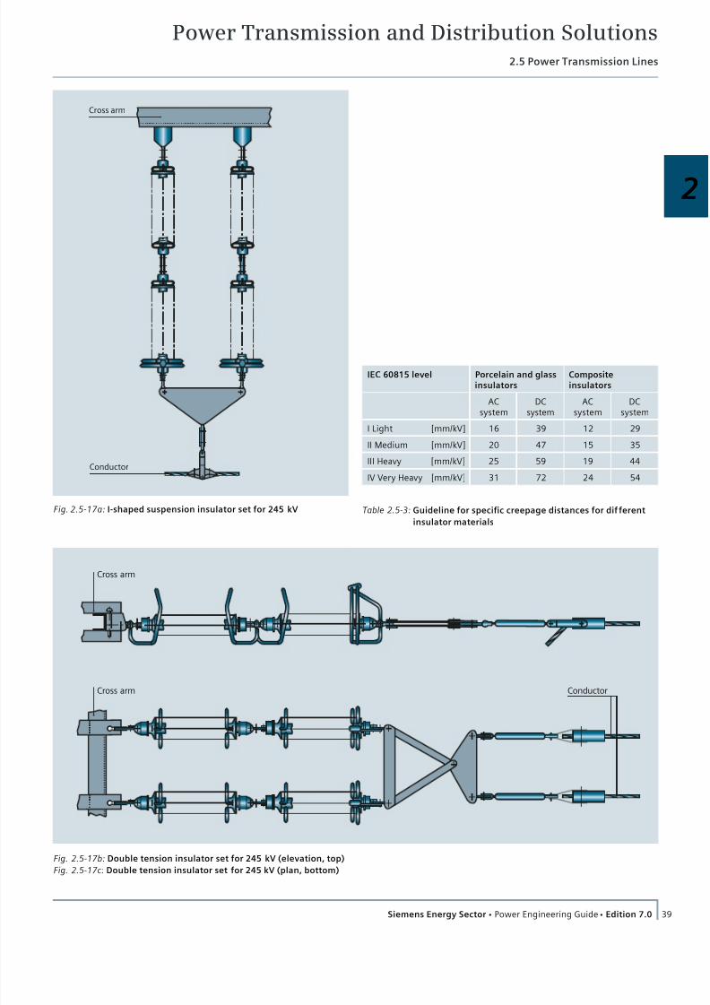
7/22/2019 Transmision y Distribucion Siemens
http://slidepdf.com/reader/full/transmision-y-distribucion-siemens 26/50
Power Transmission and Distribution Solutions2.5 Power Transmission Lines
39Siemens Energy Sector Power Engineering Guide Edition 7.0
2
Cross arm
Conductor
Fig. 2.5-17a: I-shaped suspension insulator set for 245 kV
Cross arm
ConductorCross arm
Fig. 2.5-17b: Double tension insulator set for 245 kV (elevation, top)
Fig. 2.5-17c: Double tension insulator set for 245 kV (plan, bottom)
Table 2.5-3: Guideline for specific creepage distances for dif ferent
insulator materials
IEC 60815 level Porcelain and glassinsulators
Compositeinsulators
ACsystem
DCsystem
ACsystem
DCsystem
I Light [mm/kV] 16 39 12 29
II Medium [mm/kV] 20 47 15 35
III Heavy [mm/kV] 25 59 19 44
IV Very Heavy [mm/kV] 31 72 24 54
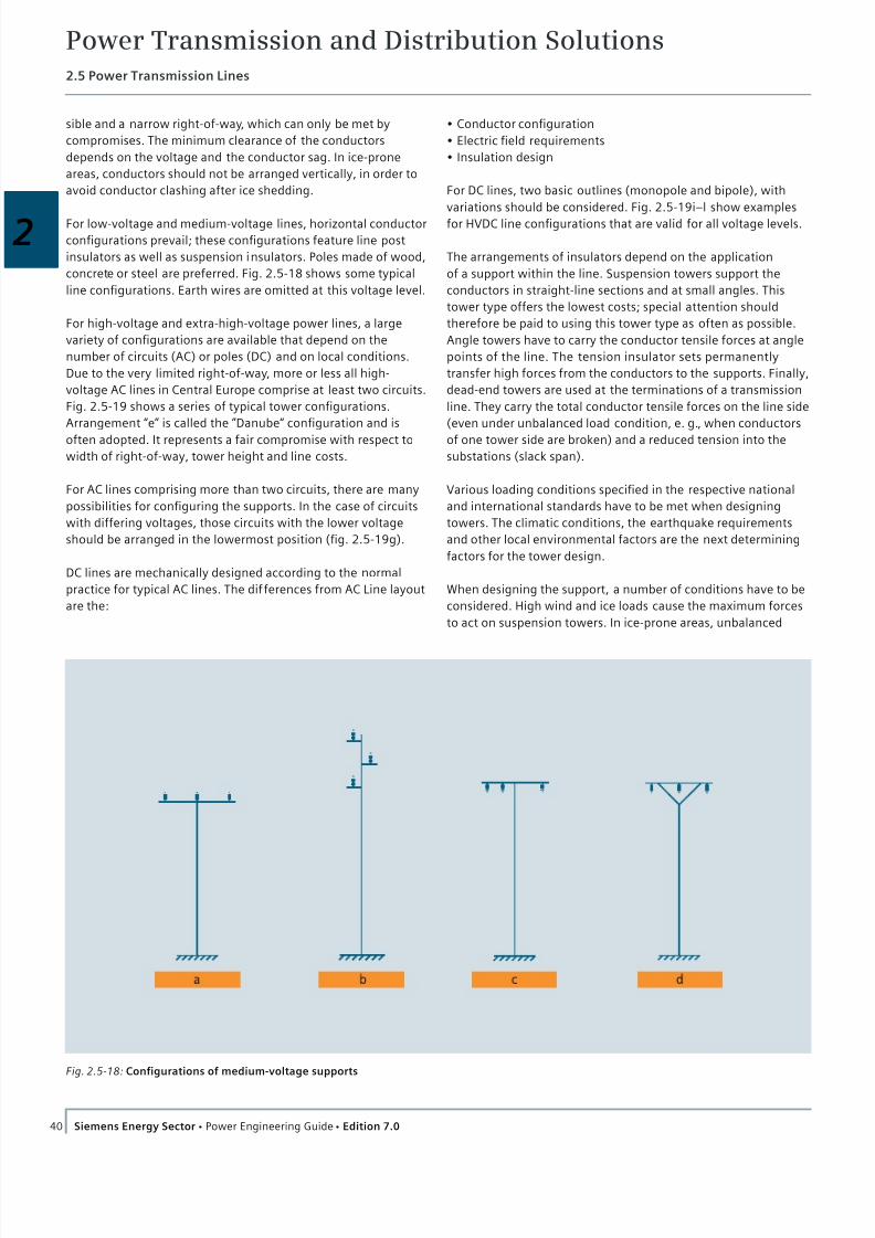
7/22/2019 Transmision y Distribucion Siemens
http://slidepdf.com/reader/full/transmision-y-distribucion-siemens 27/50
Power Transmission and Distribution Solutions2.5 Power Transmission Lines
40 Siemens Energy Sector Power Engineering Guide Edition 7.0
Conductor configuration
Electric field requirements
Insulation design
For DC lines, two basic outlines (monopole and bipole), with
variations should be considered. Fig. 2.5-19i–l show examples
for HVDC line configurations that are valid for all voltage levels.
The arrangements of insulators depend on the application
of a support within the line. Suspension towers support the
conductors in straight-line sections and at small angles. This
tower type offers the lowest costs; special attention should
therefore be paid to using this tower type as often as possible.
Angle towers have to carry the conductor tensile forces at angle
points of the line. The tension insulator sets permanently
transfer high forces from the conductors to the supports. Finally,
dead-end towers are used at the terminations of a transmission
line. They carry the total conductor tensile forces on the line side
(even under unbalanced load condition, e. g., when conductors
of one tower side are broken) and a reduced tension into the
substations (slack span).
Various loading conditions specified in the respective national
and international standards have to be met when designing
towers. The climatic conditions, the earthquake requirements
and other local environmental factors are the next determining
factors for the tower design.
When designing the support, a number of conditions have to be
considered. High wind and ice loads cause the maximum forces
to act on suspension towers. In ice-prone areas, unbalanced
sible and a narrow right-of-way, which can only be met by
compromises. The minimum clearance of the conductors
depends on the voltage and the conductor sag. In ice-prone
areas, conductors should not be arranged vertically, in order to
avoid conductor clashing after ice shedding.
For low-voltage and medium-voltage lines, horizontal conductor
configurations prevail; these configurations feature line post
insulators as well as suspension insulators. Poles made of wood,
concrete or steel are preferred. Fig. 2.5-18 shows some typical
line configurations. Earth wires are omitted at this voltage level.
For high-voltage and extra-high-voltage power lines, a large
variety of configurations are available that depend on the
number of circuits (AC) or poles (DC) and on local conditions.
Due to the very limited right-of-way, more or less all high-
voltage AC lines in Central Europe comprise at least two circuits.
Fig. 2.5-19 shows a series of typical tower configurations.
Arrangement “e” is called the ”Danube“ configuration and is
often adopted. It represents a fair compromise with respect to
width of right-of-way, tower height and line costs.
For AC lines comprising more than two circuits, there are many
possibilities for configuring the supports. In the case of circuits
with differing voltages, those circuits with the lower voltage
should be arranged in the lowermost position (fig. 2.5-19g).
DC lines are mechanically designed according to the normal
practice for typical AC lines. The dif ferences from AC Line layout
are the:
Fig. 2.5-18: Configurations of medium-voltage supports
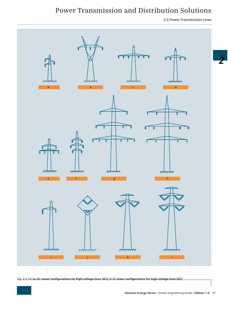
7/22/2019 Transmision y Distribucion Siemens
http://slidepdf.com/reader/full/transmision-y-distribucion-siemens 28/50
Power Transmission and Distribution Solutions2.5 Power Transmission Lines
41Siemens Energy Sector Power Engineering Guide Edition 7.0
2
Fig. 2.5-19: (a–h): tower configurations for high-voltage lines (AC); (i–l): tower configurations for high-voltage lines (DC)
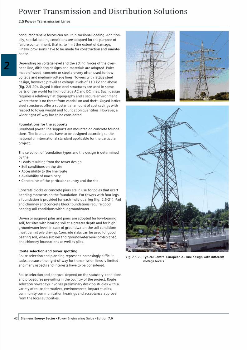
7/22/2019 Transmision y Distribucion Siemens
http://slidepdf.com/reader/full/transmision-y-distribucion-siemens 29/50
Power Transmission and Distribution Solutions2.5 Power Transmission Lines
42 Siemens Energy Sector Power Engineering Guide Edition 7.0
conductor tensile forces can result in torsional loading. Addition-
ally, special loading conditions are adopted for the purpose of
failure containment, that is, to limit the extent of damage.
Finally, provisions have to be made for construction and mainte-
nance.
Depending on voltage level and the acting forces of the over-
head line, differing designs and materials are adopted. Poles
made of wood, concrete or steel are very often used for low-
voltage and medium-voltage lines. Towers with lattice steel
design, however, prevail at voltage levels of 110 kV and above
(fig. 2.5-20). Guyed lattice steel structures are used in some
parts of the world for high-voltage AC and DC lines. Such design
requires a relatively flat topography and a secure environment
where there is no threat from vandalism and theft. Guyed lattice
steel structures offer a substantial amount of cost savings with
respect to tower weight and foundation quantities. However, a
wider right-of-way has to be considered.
Foundations for the supports
Overhead power line supports are mounted on concrete founda-
tions. The foundations have to be designed according to the
national or international standard applicable for the particular
project.
The selection of foundation types and the design is determined
by the:
Loads resulting from the tower design
Soil conditions on the site
Accessibility to the line route
Availability of machinery
Constraints of the particular country and the site
Concrete blocks or concrete piers are in use for poles that exert
bending moments on the foundation. For towers with four legs,
a foundation is provided for each individual leg (fig. 2.5-21). Pad
and chimney and concrete block foundations require good
bearing soil conditions without groundwater.
Driven or augured piles and piers are adopted for low-bearing
soil, for sites with bearing soil at a greater depth and for high
groundwater level. In case of groundwater, the soil conditions
must permit pile driving. Concrete slabs can be used for good
bearing soil, when subsoil and groundwater level prohibit pad
and chimney foundations as well as piles.
Route selection and tower spotting
Route selection and planning represent increasingly difficult
tasks, because the right-of-way for transmission lines is limited
and many aspects and interests have to be considered.
Route selection and approval depend on the statutory conditions
and procedures prevailing in the country of the project. Route
selection nowadays involves preliminary desktop studies with a
variety of route alternatives, environmental impact studies,
community communication hearings and acceptance approval
from the local authorities.
Fig. 2.5-20: Typical Central European AC line design with different
voltage levels
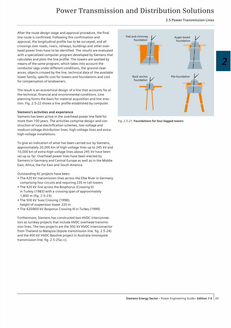
7/22/2019 Transmision y Distribucion Siemens
http://slidepdf.com/reader/full/transmision-y-distribucion-siemens 30/50
Power Transmission and Distribution Solutions2.5 Power Transmission Lines
43Siemens Energy Sector Power Engineering Guide Edition 7.0
2
After the route design stage and approval procedure, the final
line route is confirmed. Following this confirmation and
approval, the longitudinal profile has to be surveyed, and all
crossings over roads, rivers, railways, buildings and other over-
head power lines have to be identified. The results are evaluated
with a specialized computer program developed by Siemens that
calculates and plots the line profile. The towers are spotted by
means of the same program, which takes into account the
conductor sags under different conditions, the ground clear-
ances, objects crossed by the line, technical data of the available
tower family, specific cost for towers and foundations and cost
for compensation of landowners.
The result is an economical design of a line that accounts for all
the technical, financial and environmental conditions. Line
planning forms the basis for material acquisition and line erec-
tion. Fig. 2.5-22 shows a line profile established by computer.
Siemens’s activities and experience
Siemens has been active in the overhead power line field for
more than 100 years. The activities comprise design and con-
struction of rural electrification schemes, low-voltage and
medium-voltage distribution lines, high-voltage lines and extra-
high-voltage installations.
To give an indication of what has been carried out by Siemens,
approximately 20,000 km of high-voltage lines up to 245 kV and
10,000 km of extra-high-voltage lines above 245 kV have been
set up so far. Overhead power lines have been erected by
Siemens in Germany and Central Europe as well as in the Middle
East, Africa, the Far East and South America.
Outstanding AC projects have been:
The 420 kV transmission lines across the Elbe River in Germany
comprising four circuits and requiring 235 m tall towers
The 420 kV line across the Bosphorus (Crossing II)
in Turkey (1983) with a crossing span of approximately
1,800 m (fig. 2.5-23).
The 500 kV Suez Crossing (1998);
height of suspension tower 220 m
The 420/800 kV Bosporus Crossing III in Turkey (1999)
Furthermore, Siemens has constructed two HVDC interconnec-
tors as turnkey projects that include HVDC overhead transmis-
sion lines. The two projects are the 300 kV HVDC interconnector
from Thailand to Malaysia (bipole transmission line, fig. 2.5-24)and the 400 kV HVDC Basslink project in Australia (monopole
transmission line, fig. 2.5-25a–c).
Pad-and-chimneyfoundation
Rock anchorfoundation
Auger-boredfoundation
Pile foundation
Fig. 2.5-21: Foundations for four-legged towers
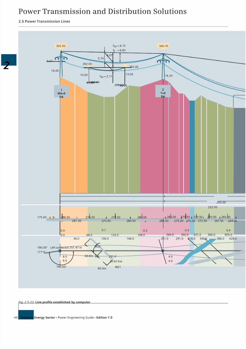
7/22/2019 Transmision y Distribucion Siemens
http://slidepdf.com/reader/full/transmision-y-distribucion-siemens 31/50
Power Transmission and Distribution Solutions2.5 Power Transmission Lines
44 Siemens Energy Sector Power Engineering Guide Edition 7.0
2T+0DH
1WA+0
DA
300.70302.50
232.50
255.00
16.2013.00
292.00
279.00282.00
10.00
16.00
0.47292.00
5.746.07
f40 = 6.15
fE = 6.60
f40 = 2.11
281.50286.50 276.50
273.00273.50 280.00
280.50 284.50
283.00
275.00
275.50
270.50
270.50
272.50
270.00
267.50
265.00
264.00
o. D.175.00
36.00.0 66.0
106.0132.0 194.0
166.0 251.0
264.0
291.0
302.0
316.0
331.0
346.0
360.0
386.0
405.0
426.0
0.0 0.1 0.2 0.3 0.4
190.00°
171°0´
Left conductor 251.47 m
190.00°
6.0
6.0
M20
251.0
M2160.0m
60.0m 50°
20 kV line 4.0
4.0
Fig. 2.5-22: Line profile established by computer

7/22/2019 Transmision y Distribucion Siemens
http://slidepdf.com/reader/full/transmision-y-distribucion-siemens 32/50
Power Transmission and Distribution Solutions2.5 Power Transmission Lines
45Siemens Energy Sector Power Engineering Guide Edition 7.0
2
4WA+0
DA
223.00
284.20
3T+8
DH
Earth wire: ACSR 265/35 * 80.00 N/mm2
Conductor: ACSR 265/35 * 80.00 N/mm2
Equivalent sag: 11.21 m at 40 °C
Equivalent span: 340.44 m
Arable land
ForestFallow land
Road
Stream
Meadow
270.00
292.50
16.00
1.45
f40 = 5.56
fE = 5.87
24.20
Bushes, height up to 5 m
16.75
15.86
7.55
8.44
17.30
16.38
11.38
12.29
f40 = 17.46fE = 16.52
263.00
263.00
266.50
265.50
264.00
261.50
258.50
260.00
260.00
260.00
247.50
236.00
229.00
223.00
215.50
209.00
207.00
462.0
506.0
534.0
544.0
586.0
626.0
666.0
676.0
688.0
744.0
776.0
804.0
826.0
848.0
904.0
910.0
0.5 0.6 0.7 0.8 0.9
425.0 13.9°
Road crossing
at km 10.543
4.0
4.0 234.0
169.00°
5.8
Left conductor 235.45 mRoad to XXX 169.00°
152°6´
5.8

7/22/2019 Transmision y Distribucion Siemens
http://slidepdf.com/reader/full/transmision-y-distribucion-siemens 33/50
Power Transmission and Distribution Solutions2.5 Power Transmission Lines
46 Siemens Energy Sector Power Engineering Guide Edition 7.0
Tension tower Tension towerSuspension tower Suspension tower
Conductor: 4x3x1 AACSR/AW 1802/226 mm2 on 420 kV
Upgradeable to 2x3x2 AACSR/A W 1802/226 mm2
on 800 kV
Shieldwire: 2x (ASLH-DBBB 1x22E8/125 - A W 33)
Dimensions in m
73
160
153
158
160
64
88 127
64
728 1,884 502
Fig. 2.5-23: 420/800 kV line across the Bosphorus, longitudinal profile
Fig. 2.5-25a: 400 kV HVDC Basslink project in Australia
(monopole transmission line)
Fig. 2.5-24: 300kV HVDC interconnector from Thailand to Malaysia
(bipole transmission line)
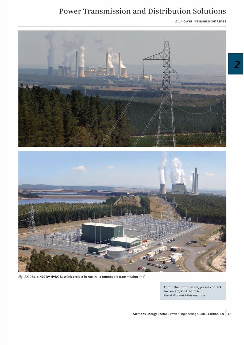
7/22/2019 Transmision y Distribucion Siemens
http://slidepdf.com/reader/full/transmision-y-distribucion-siemens 34/50
Power Transmission and Distribution Solutions2.5 Power Transmission Lines
47Siemens Energy Sector Power Engineering Guide Edition 7.0
2
For further information, please contact:
Fax: ++49 (0)91 31 7-3 20 94
E-mail: [email protected]
Fig. 2.5-25b, c: 400 kV HVDC Basslink project in Australia (monopole transmission line)
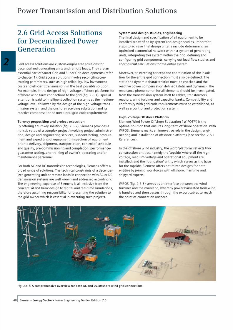
7/22/2019 Transmision y Distribucion Siemens
http://slidepdf.com/reader/full/transmision-y-distribucion-siemens 35/50
Power Transmission and Distribution Solutions
48 Siemens Energy Sector Power Engineering Guide Edition 7.0
2.6 Grid Access Solutionsfor Decentralized PowerGeneration
Grid access solutions are custom-engineered solutions for
decentralized generating units and remote loads. They are an
essential part of Smart Grid and Super Grid developments (refer
to chapter 1). Grid access solutions involve reconciling con-
trasting parameters, such as high reliability, low investment
costs and efficient transmission, in the best possible solution.
For example, in the design of high-voltage offshore platforms for
offshore wind farm connections to the grid (fig. 2.6-1), special
attention is paid to intelligent collection systems at the medium-
voltage level, followed by the design of the high-voltage trans-
mission system and the onshore receiving substation and its
reactive compensation to meet local grid code requirements.
Turnkey proposition and project execution
By offering a turnkey solution (fig. 2.6-2), Siemens provides a
holistic setup of a complex project involving project administra-
tion, design and engineering services, subcontracting, procure-
ment and expediting of equipment, inspection of equipment
prior to delivery, shipment, transportation, control of schedule
and quality, pre-commissioning and completion, performance-
guarantee testing, and training of owner’s operating and/or
maintenance personnel.
For both AC and DC transmission technologies, Siemens offers a
broad range of solutions. The technical constraints of a decentral-
ized generating unit or remote loads in connection with AC or DC
transmission systems are well known and addressed accordingly.
The engineering expertise of Siemens is all inclusive from the
conceptual and basic design to digital and real-time simulations,
therefore assuming responsibility for presenting the solution to
the grid owner which is essential in executing such projects.
System and design studies, engineering
The final design and specification of all equipment to be
installed are verified by system and design studies. Important
steps to achieve final design criteria include determining an
optimized economical network within a system of generating
units, integrating this system within the grid, defining and
configuring grid components, carrying out load flow studies and
short-circuit calculations for the entire system.
Moreover, an earthing concept and coordination of the insula-
tion for the entire grid connection must also be defined. The
static and dynamic characteristics must be checked and the
reactive power compensation defined (static and dynamic). The
resonance phenomenon for all elements should be investigated,
from the transmission system itself to cables, transformers,
reactors, wind turbines and capacitor banks. Compatibility and
conformity with grid code requirements must be established, as
well as a control and protection system.
High-Voltage Offshore Platform
Siemens Wind Power Offshore Substation ( WIPOS™) is the
optimal solution that ensures long-term offshore operation. With
WIPOS, Siemens marks an innovative role in the design, engi-
neering and installation of offshore platforms (see section 2.6.1
References).
In the offshore wind industry, the word ‘platform’ reflects two
construction entities, namely the ‘topside’ where all the high-
voltage, medium-voltage and operational equipment are
installed, and the ‘foundation’ entity which serves as the base
for the topside. Siemens offers optimized designs for both
entities by joining workforces with offshore, maritime and
shipyard experts.
WIPOS (fig. 2.6-3) serves as an interface between the wind
turbines and the mainland, whereby power harvested from wind
is bundled and then passes through the export cables to reach
the point of connection onshore.
Fig. 2.6-1: A comprehensive overview for both AC and DC offshore wind grid connections

7/22/2019 Transmision y Distribucion Siemens
http://slidepdf.com/reader/full/transmision-y-distribucion-siemens 36/50
Power Transmission and Distribution Solutions2.6 Grid Access Solutions for Decentralized Power Generation
49Siemens Energy Sector Power Engineering Guide Edition 7.0
2
Fig. 2.6-2: Siemens executes projects as on EPC Contractor
A typical topside comprises a multi-deck construction with the
main deck, where all electro-technical equipment is installed, as
well as a helideck for helicopter landing designed to meet
aviation regulations.
From a complete platform approach, Siemens also of fers the
self-lifting platform concept due to its versatility in function, and
the possibility for transportations and installation without
exorbitant efforts by avoiding heavy crane vessels.
Siemens offers a family of WIPOS designs with the flexibility to
meet various offshore weather, tide and seabed conditions with
three main configurations:
WIPOS self-lifting solution
WIPOS topside solution (topside/jacket)
WIPOS floating solution
Fig. 2.6-3: A model of Siemens’ Windpower Offshore Substation
(WIPOS): Siemens supplies comprehensive offshore
grid connection solutions with flexible substation
configurations for both AC and DC applications
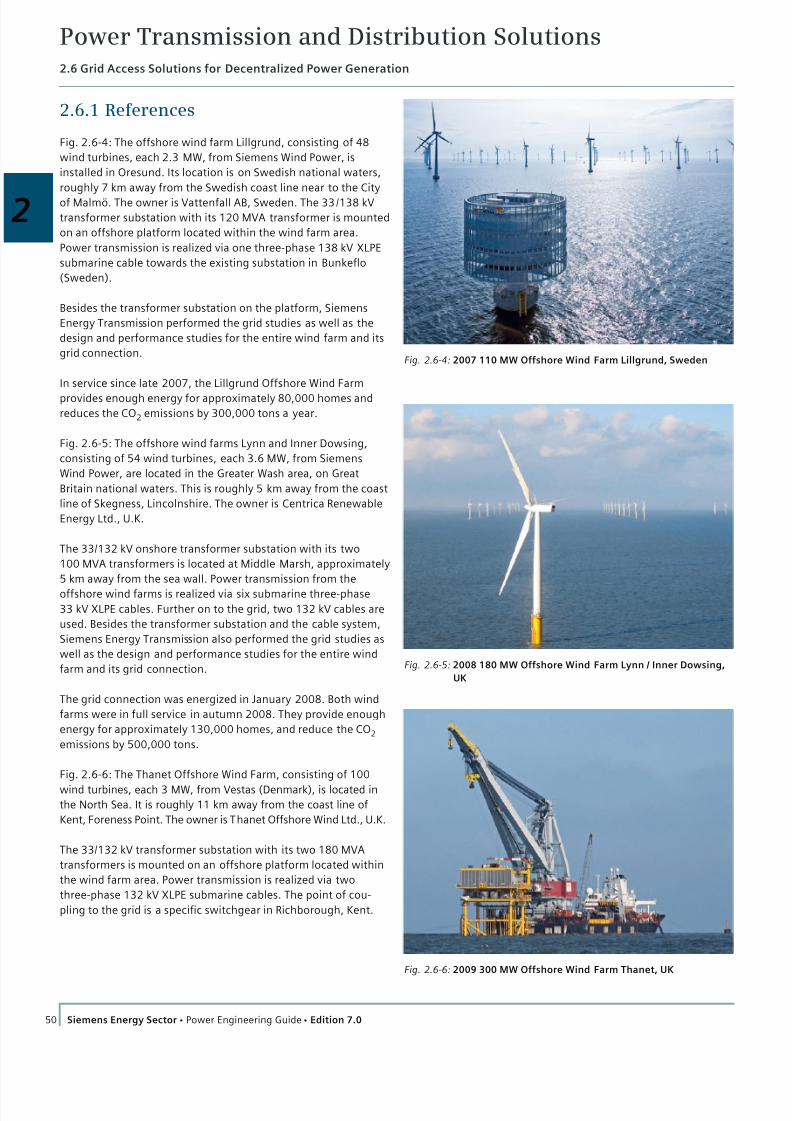
7/22/2019 Transmision y Distribucion Siemens
http://slidepdf.com/reader/full/transmision-y-distribucion-siemens 37/50
Power Transmission and Distribution Solutions2.6 Grid Access Solutions for Decentralized Power Generation
50 Siemens Energy Sector Power Engineering Guide Edition 7.0
2.6.1 References
Fig. 2.6-4: The offshore wind farm Lillgrund, consisting of 48
wind turbines, each 2.3 MW, from Siemens Wind Power, is
installed in Oresund. Its location is on Swedish national waters,
roughly 7 km away from the Swedish coast line near to the City
of Malmö. The owner is Vattenfall AB, Sweden. The 33/138 kV
transformer substation with its 120 MVA transformer is mounted
on an offshore platform located within the wind farm area.
Power transmission is realized via one three-phase 138 kV XLPE
submarine cable towards the existing substation in Bunkeflo
(Sweden).
Besides the transformer substation on the platform, Siemens
Energy Transmission performed the grid studies as well as the
design and performance studies for the entire wind farm and its
grid connection.
In service since late 2007, the Lillgrund Offshore Wind Farm
provides enough energy for approximately 80,000 homes and
reduces the CO2 emissions by 300,000 tons a year.
Fig. 2.6-5: The offshore wind farms Lynn and Inner Dowsing,
consisting of 54 wind turbines, each 3.6 MW, from Siemens
Wind Power, are located in the Greater Wash area, on Great
Britain national waters. This is roughly 5 km away from the coast
line of Skegness, Lincolnshire. The owner is Centrica Renewable
Energy Ltd., U.K.
The 33/132 kV onshore transformer substation with its two
100 MVA transformers is located at Middle Marsh, approximately
5 km away from the sea wall. Power transmission from the
offshore wind farms is realized via six submarine three-phase
33 kV XLPE cables. Further on to the grid, two 132 kV cables are
used. Besides the transformer substation and the cable system,
Siemens Energy Transmission also performed the grid studies as
well as the design and performance studies for the entire wind
farm and its grid connection.
The grid connection was energized in January 2008. Both wind
farms were in full service in autumn 2008. They provide enough
energy for approximately 130,000 homes, and reduce the CO2
emissions by 500,000 tons.
Fig. 2.6-6: The Thanet Offshore Wind Farm, consisting of 100
wind turbines, each 3 MW, from Vestas (Denmark), is located in
the North Sea. It is roughly 11 km away from the coast line of
Kent, Foreness Point. The owner is Thanet Offshore Wind Ltd., U.K.
The 33/132 kV transformer substation with its two 180 MVA
transformers is mounted on an offshore platform located within
the wind farm area. Power transmission is realized via two
three-phase 132 kV XLPE submarine cables. The point of cou-
pling to the grid is a specific switchgear in Richborough, Kent.
Fig. 2.6-6: 2009 300 MW Offshore Wind Farm Thanet, UK
Fig. 2.6-4: 2007 110 MW Offshore Wind Farm Lillgrund, Sweden
Fig. 2.6-5: 2008 180 MW Offshore Wind Farm Lynn / Inner Dowsing,
UK

7/22/2019 Transmision y Distribucion Siemens
http://slidepdf.com/reader/full/transmision-y-distribucion-siemens 38/50
Power Transmission and Distribution Solutions2.6 Grid Access Solutions for Decentralized Power Generation
51Siemens Energy Sector Power Engineering Guide Edition 7.0
2
Fig. 2.6-7: 2010 500 MW Offshore Greater Gabbard, UK
London
Clacton-on-Sea
London Array
Fig. 2.6-8: 2012 630 MW London Array , UK
Apart from the offshore transformer substation, the onshore
substation with its compensation systems (two SVC PLUS) and
harmonic filters, as well as the cable system, Siemens Energy
Transmission also performed the grid studies as well as the
design and performance studies for the entire wind farm and its
grid connection.
The grid connection was energized in autumn 2009, with all 100
wind turbines running by autumn 2010. Now the offshore wind
farm provides enough energy for approximately 215,000 homes,
and reduces the CO2 emissions by 830,000 tons a year.
Fig. 2.6-7: The Greater Gabbard offshore wind farm, planned
with 140 wind turbines, each 3.6 MW, from Siemens Wind
Power (Denmark), is located in the North Sea close to the
Thames Estuary. It is roughly 26 km (respective 46 km) away
from the coast line of Suffolk.
The owner is Greater Gabbard Offshore Winds Ltd., U.K. The
33/132 kV transformer substation with its three 180 MVA trans-
formers is mounted on two offshore platforms (Inner Gabbard
and Galloper) located within the wind farm area. Power trans-
mission is realized via three three-phase 132 kV XLPE submarine
cables.
The point of coupling to the grid is realized in Sizewell Village,
Suffolk, where Siemens built a reactive power compensation
substation to allow the wind farm to meet the requirements of
the GB grid code. SVC PLUS multilevel technology is used for all
of the three export circuits.
Here again, Siemens Energy Transmission performed the grid
studies as well as the design and performance studies for the
entire wind farm.
Now the offshore wind farm provides enough energy for approx-
imately 350,000 homes and reduces the CO2 emissions by
1,350,000 tons a year.
Fig. 2.6-8: In September 2009, Siemens was awarded a contract
for the first phase of the offshore grid access solution to the
prestigious London Array wind farm.
The grid access project was completed in two phases. In phase
one, two offshore substations (each with two 150 MVA trans-
formers) will be delivered to collect the 630 MW of power
generated from 175 wind turbines – also supplied by Siemens
– before transferring it to shore via the main 150 kV export
cables.
Siemens is responsible for the turnkey construction of the
onshore substation. As for the two offshore substations,
Siemens is responsible for the overall layout design to ensure
that the facility functions as a substation, including all primary
and secondary equipment as well as testing and commissioning.
Situated 24 km from Clacton-on-Sea, Essex, the system will
generate 1,000 MW of green power, enough to supply the
electricity needs for nearly 600,000 homes across the South East
of England, and will be the largest offshore wind farm in the
world in 2012.
For further information:
http://www.siemens.com/energy/grid-access-solutions
http://www.siemens.com/energy/wipos
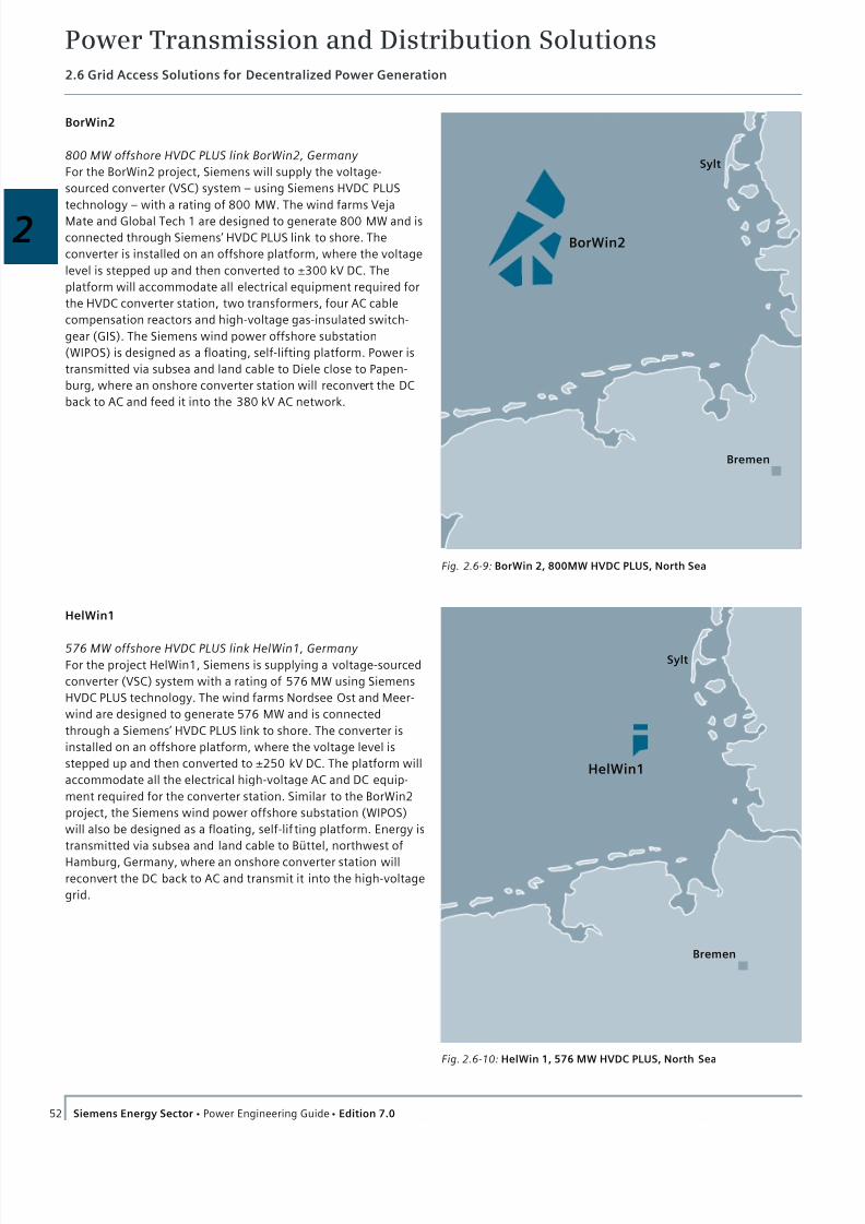
7/22/2019 Transmision y Distribucion Siemens
http://slidepdf.com/reader/full/transmision-y-distribucion-siemens 39/50
Power Transmission and Distribution Solutions2.6 Grid Access Solutions for Decentralized Power Generation
52 Siemens Energy Sector Power Engineering Guide Edition 7.0
BorWin2
800 MW offshore HVDC PLUS link BorWin2, Germany
For the BorWin2 project, Siemens will supply the voltage-
sourced converter (VSC) system – using Siemens HVDC PLUS
technology – with a rating of 800 MW. The wind farms Veja
Mate and Global Tech 1 are designed to generate 800 MW and is
connected through Siemens’ HVDC PLUS link to shore. The
converter is installed on an offshore platform, where the voltage
level is stepped up and then converted to ±300 kV DC. The
platform will accommodate all electrical equipment required for
the HVDC converter station, two transformers, four AC cable
compensation reactors and high-voltage gas-insulated switch-
gear (GIS). The Siemens wind power offshore substation
(WIPOS) is designed as a floating, self-lifting platform. Power is
transmitted via subsea and land cable to Diele close to Papen-
burg, where an onshore converter station will reconvert the DC
back to AC and feed it into the 380 kV AC network.
Sylt
nemerB
HelWin1
Fig. 2.6-10: HelWin 1, 576 MW HVDC PLUS, North Sea
Sylt
nemerB
BorWin2
Fig. 2.6-9: BorWin 2, 800MW HVDC PLUS, North Sea
HelWin1
576 MW offshore HVDC PLUS link HelWin1, Germany
For the project HelWin1, Siemens is supplying a voltage-sourced
converter (VSC) system with a rating of 576 MW using Siemens
HVDC PLUS technology. The wind farms Nordsee Ost and Meer-
wind are designed to generate 576 MW and is connected
through a Siemens’ HVDC PLUS link to shore. The converter is
installed on an offshore platform, where the voltage level is
stepped up and then converted to ±250 kV DC. The platform will
accommodate all the electrical high-voltage AC and DC equip-
ment required for the converter station. Similar to the BorWin2
project, the Siemens wind power offshore substation (WIPOS)
will also be designed as a floating, self-lif ting platform. Energy is
transmitted via subsea and land cable to Büttel, northwest of
Hamburg, Germany, where an onshore converter station will
reconvert the DC back to AC and transmit it into the high-voltage
grid.
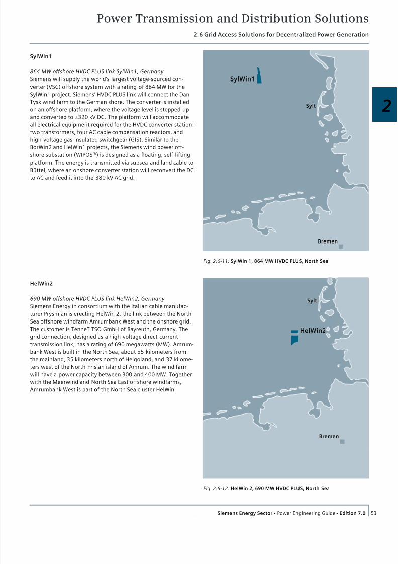
7/22/2019 Transmision y Distribucion Siemens
http://slidepdf.com/reader/full/transmision-y-distribucion-siemens 40/50
Power Transmission and Distribution Solutions2.6 Grid Access Solutions for Decentralized Power Generation
53Siemens Energy Sector Power Engineering Guide Edition 7.0
2
Sylt
nemerB
HelWin2
Fig. 2.6-12: HelWin 2, 690 MW HVDC PLUS, North Sea
Sylt
Bremen
SylWin1
Fig. 2.6-11: SylWin 1, 864 MW HVDC PLUS, North Sea
SylWin1
864 MW offshore HVDC PLUS link SylWin1, Germany
Siemens will supply the world’s largest voltage-sourced con-
verter (VSC) offshore system with a rating of 864 MW for the
SylWin1 project. Siemens’ HVDC PLUS link will connect the Dan
Tysk wind farm to the German shore. The converter is installed
on an offshore platform, where the voltage level is stepped up
and converted to ±320 kV DC. The platform will accommodate
all electrical equipment required for the HVDC converter station:
two transformers, four AC cable compensation reactors, and
high-voltage gas-insulated switchgear (GIS). Similar to the
BorWin2 and HelWin1 projects, the Siemens wind power off-
shore substation (WIPOS®) is designed as a floating, self-lifting
platform. The energy is transmitted via subsea and land cable to
Büttel, where an onshore converter station will reconvert the DC
to AC and feed it into the 380 kV AC grid.
HelWin2
690 MW offshore HVDC PLUS link HelWin2, Germany
Siemens Energy in consortium with the Italian cable manufac-
turer Prysmian is erecting HelWin 2, the link between the North
Sea offshore windfarm Amrumbank West and the onshore grid.
The customer is TenneT TSO GmbH of Bayreuth, Germany. The
grid connection, designed as a high-voltage direct-current
transmission link, has a rating of 690 megawatts (MW). Amrum-
bank West is built in the North Sea, about 55 kilometers from
the mainland, 35 kilometers north of Helgoland, and 37 kilome-
ters west of the North Frisian island of Amrum. The wind farm
will have a power capacity between 300 and 400 MW. Together
with the Meerwind and North Sea East offshore windfarms,
Amrumbank West is part of the North Sea cluster HelWin.

7/22/2019 Transmision y Distribucion Siemens
http://slidepdf.com/reader/full/transmision-y-distribucion-siemens 41/50
Power Transmission and Distribution Solutions
54 Siemens Energy Sector Power Engineering Guide Edition 7.0
2.7 Solar Power Solutions
Photovoltaic (PV) systems convert sunlight directly into electrical
energy without any environmentally harmful emissions, and
thus reduce dependence on expensive and ending fossil energy
sources. Government stimulation programs and the increase in
efficiency are making PV systems more and more attractive for
investors as well as power supply companies. Yields can be
obtained by feeding solar electricity into the grid.
The three main application areas are:
Grid-connected photovoltaic systems:
These photovoltaic systems (from 5 kWp to 50 MWp) are
connected to the grid and generate alternating current that is
fed into the grid or used directly on the site.
Stand-alone photovoltaic systems:
Stand-alone photovoltaic systems equipped with batteries for
storing electricity are used to supply power to areas that have
no connection to the grid.
Hybrid systems for back-up supply in regions where the public
supply is unreliable.
Components and mode of operation
A grid-connected PV system typically consists of the following
components:
Solar modules
Cabling
Inverters and switchgears
Metering
Connection to the public grid
Solar cells absorb sunlight and transform it into electrical
energy, thereby generating direct current. Several solar cel ls
wired together form a solar module. Solar cells are usually
manufactured from either monocrystalline or polycrystalline
silicon. The use of thin-layer modules is also becoming increas-
ingly common. The modules are connected in series and com-
bined into arrays. The arrays are connected to the inverter via
several connection boxes. Centralized inverter combinations
convert the direct current generated by the solar modules into
alternating current that than can be fed into the grid. Optimum
electrical and structural engineering forms the basis for max-
imum efficiency and a high degree of reliability.
SINVERTsolar inverter unitsThe core elements of grid-connected PV systems are the power
inverters. With its SINVERTsolar range of inverter units, Siemens
offers certified series-manufactured products that comply with
all important national and international safety standards. Thanks
to their electromagnetic compatibility (EMC) compliant construc-
tion, they are even suitable for operation in areas susceptible to
electromagnetic interference.
Large subsystems up to 1.6 MVA peak capacity (master/slave
combination) can also be implemented with SINVERTsolar
inverters. The devices, which are based on IGBT technology, can
attain an efficiency of up to 97 %, because they are optimized
for extremely low losses. Master/slave operation has the advan-
tage that the inverters can always be operated close to the
optimum efficiency range. If, for example, solar irradiation
decreases, superfluous inverters can be switched off automati-
cally and the remaining inverters loaded more effectively so that
the maximum possible electricity yield can flow into the grid. At
night the inverters are switched off, to reduce their time of
operation and increase the lifetime.
Requirements for PV systems for buildings
When planning a photovoltaic system, numerous structural
engineering requirements must be taken into account, because
often no allowance was made for installing photovoltaic systems
when a building was first constructed. For many years, Siemens
has been developing highly flexible structural and electrical
engineering solutions for specific applications for the production
of solar electricity. The following factors directly influence
efficiency and hence cost-effectiveness when planning and
installing a PV system:
Location of the system (maximum solar irradiation)
Orientation of the system (due south is optimal)
Quality of the products (optimally matched)
Engineering excellence (electrical/mechanical combination)
The following building integrated systems are available:
Facade-mounted system (fig. 2.7-1a)
Roof-mounted system (fig. 2.7-1c)
Flat-roof installation
Special structural engineering solutions (fig. 2.7-1b)
Planning guidelines
When planning a grid-connected PV system (fig. 2.7-2),
the following points must be clarified in advance:
Choice of the ideal application and orientation
(solar irradiation)
Choice of the ideal system:
– Deciding on the total capacity of the system,
depending on the investment volume and the area
available for the installation
– Drawing up a financing plan
– Statical calculation of the load-bearing capacity
of the roof or facade
– Electrical and mechanical engineering
– Determining whether feeding into the grid is possible and
making an application to the local distribution network
operator
Electricity from roof and facade-mounted systems is usually fed
into the low-voltage or medium-voltage system of the local
distribution network operator as a 3-phase current. The type of
current that is fed into the grid should be clarified with the local
distribution network operator in each individual case.
Planning process
Siemens supports the planning process with advice from experts
about economical and technical aspects and basic and detailed
engineering. Siemens can also help to devise the financing plan.
Projects, located in the Netherlands, can offer the following
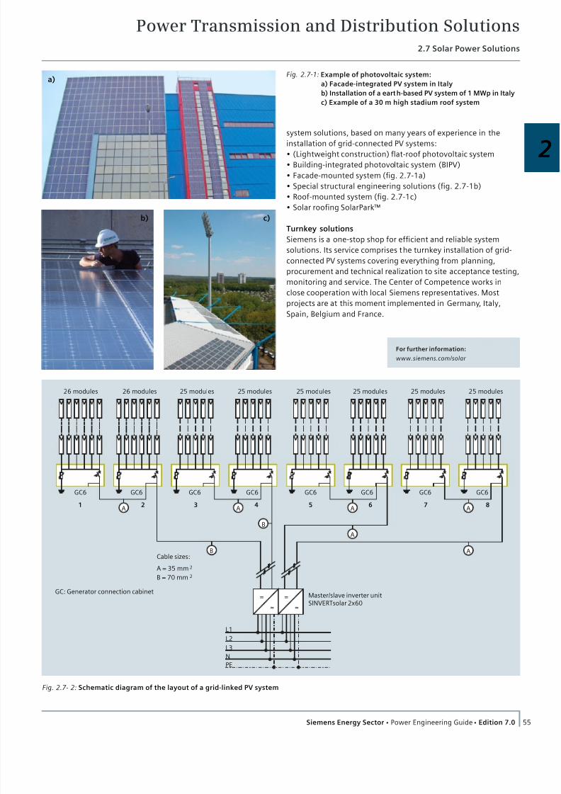
7/22/2019 Transmision y Distribucion Siemens
http://slidepdf.com/reader/full/transmision-y-distribucion-siemens 42/50
Power Transmission and Distribution Solutions2.7 Solar Power Solutions
55Siemens Energy Sector Power Engineering Guide Edition 7.0
2
system solutions, based on many years of experience in the
installation of grid-connected PV systems:
(Lightweight construction) flat-roof photovoltaic system
Building-integrated photovoltaic system (BIPV)
Facade-mounted system (fig. 2.7-1a)
Special structural engineering solutions (fig. 2.7-1b)
Roof-mounted system (fig. 2.7-1c)
Solar roofing SolarPark™
Turnkey solutions
Siemens is a one-stop shop for efficient and reliable system
solutions. Its service comprises the turnkey installation of grid-
connected PV systems covering everything from planning,
procurement and technical realization to site acceptance testing,
monitoring and service. The Center of Competence works in
close cooperation with local Siemens representatives. Most
projects are at this moment implemented in Germany, Italy,
Spain, Belgium and France.
GC6
1
L1
L2
L3
N
PE
2 3 4 5 6 7 8A
= =
≈ ≈
A = 35 mm
Cable sizes:
Master/slave inverter unitSINVERTsolar 2x60
26 modules 26 modules 25 modules 25 modules 25 modules 25 modules 25 modules 25 modules
2
B = 70 mm 2
GC6 GC6 GC6 GC6 GC6 GC6 GC6
A
B
A
A
B
A
A
GC: Generator connection cabinet
Fig. 2.7- 2: Schematic diagram of the layout of a grid-linked PV system
For further information:
www.siemens.com/solar
Fig. 2.7-1: Example of photovoltaic system:
a) Facade-integrated PV system in Italy
b) Installation of a earth-based PV system of 1 MWp in Italy
c) Example of a 30 m high stadium roof system
a)
b) c)

7/22/2019 Transmision y Distribucion Siemens
http://slidepdf.com/reader/full/transmision-y-distribucion-siemens 43/50
Power Transmission and Distribution Solutions
56 Siemens Energy Sector Power Engineering Guide Edition 7.0
2.8 SIESTORAGE
2.8.1 The Modular Energy StorageSystem for a Sustainable Energy
Supply
The challenge: reliable energy supply! Distributed, renewable
energy sources, such as wind turbines and photovoltaic plants,
are making a bigger and bigger contribution to the energy mix
of the public power supply (fig. 2.8-1). However, as the amount
of electrical power they generate cannot be predicted, their
increasing use is creating new challenges in terms of system
stability, integration into the power supply system, operating
reserves, quality of voltage and supply, as well as peak load
management.
The answer: SIESTORAGE – Siemens Energy Storage – the
sustainable and eco-friendly solution! Energy storage systems
are the right solution in all these cases. SIESTORAGE ensures a
sufficient amount of available reserve power for balancing and
regulation purposes, especially of renewable energy sources,
and creates higher system stability for industry, buildings and
infrastructure. Energy that is stored by the system can be
regained in case of demand. Generation outages can be com-
pensated for minutes and even for hours on end. SIESTORAGE
combines cutting-edge power electronics for power system
applications with high-performance lithium-ion-batteries. With a
compact battery and converter cabinet as the smallest unit, the
capacity of the SIESTORAGE system can be expanded to up to 2
megawatt hours, and its output up to 8 megawatts (fig. 2.8-2).
The advantages at a glance
The SIESTORAGE energy storage system from Siemens is ideally
suited to various applications. Compared to other energy storage
solutions, it has a number of additional advantages, such as:
High degree of availability and reliability thanks to modular
design
Suitable for all requirements due to highest flexibility
Easy handling of battery modules (safe low voltage) ensures
the highest degree of safety for system an persons
Completely integrated turnkey solution thoughout the entire
life cycle
Parallel connection of energy storage cabinets on AC sideensures the highest flexibility
Prowen expertence in power electronics for power system
applications
Black start capability for microgrid application
Emissions-free solution and improvement of CO2 footprint
Always the right storage solution
Modular design (fig. 2.8-3)
SIESTORAGE is a modular energy storage solution. Batteries and
control electronics are inserted in cabinets as plug-in units. One
energy storage cabinet contains up to 16 battery modules, each
Fig. 2.8-1: SIESTORAGE offers solutions for distribution systems with
a high share of distributed renewable energy sources
Powerful combination:
Cutting-edge powerelectronics and high-powerLi-ion batteries
Variable through modularity:
In power and capacity withparallel connection ofcombined energy storagecabinets on the AC side
Adequate capacity:
Up to about 2 MWh
Top performance:
Modular up to about 8 MW
Power system
AC/DCinverter
Filter
Transformer
Medium-voltage switchgear
Li-ionbatterysystem n
c e l l s
i n s e r i e s
S I P L I N K
Smart Network Control
Invertercontrol
Data logging
Batterymanagement
System control
Fig. 2.8-2: A modular energy storage solution based on proven
components
with a maximum voltage of 60 V DC. The individual battery mod-
ules can be pulled out, inserted and moved safely. The required
power and capacity are achieved through a parallel connection
of several cabinets on their AC side. Both parameters can be
adapted to fit the particular requirements of a project.
The intelligent Battery Management System (BMS) monitors
state of charge, voltage and temperature of the individual
battery modules, among others. SIESTORAGE’s core is the SIP-
LINK converter product platform. The batteries are charged and
discharged at the AC system using SIPLINK active front ends. The
SIPLINK power electronics were developed especially for sophis-
ticated system applications such as MVDC system couplings, and
are the basis of the various SIESTORAGE applications.
The control components for the entire storage unit are accom-
modated in a separate cabinet. A combined control and system
connection cabinet is used for up to four energy storage cabi-
nets. The system is controlled with SIMATIC S7, either on site or
over the Internet. Information on the system’s operating state,
for instance on batteries, auxiliary systems, medium-voltage
switchgear and error messages, are displayed on the human
machine interface (HMI).

7/22/2019 Transmision y Distribucion Siemens
http://slidepdf.com/reader/full/transmision-y-distribucion-siemens 44/50
Power Transmission and Distribution Solutions2.8 SIESTORAGE
57Siemens Energy Sector Power Engineering Guide Edition 7.0
2
Combined energy storage cabinet (batteries + converter)
for up to 16 battery modules up to 24 kWh / 144 kWp
Fully equipped energy storage cabinet
including power electronics
Drawer for up to8 battery modules
Drawer for up to8 battery modules
Battery module
Battery management
SIPLINK converter
Fig. 2.8-3: Batteries and control electronics are inserted in cabinets as plug-in units, thus facilitates the exchange of individual units
Up to 12 energy storage cabinets are connected to one control
cabinet and one system connection cabinet. This results in
additional redundancy in the control system of larger units
(tab 2.8-1).
Integrated containerized solution
Up to 24 energy storage cabinets can be installed in a container.
Systems larger than 2 MVA/500 kWh can be scaled with several
containers. The storage unit can be connected to the MV system
with a medium-voltage transformer and switchgear. The integra-
tion of the cabinets into a containerized enclosure ensures a
particularly easy application (fig. 2.8-4). It is easy to transport
the containers, and they can be positioned flexibly. An air-condi-
tioning system makes smooth operation possible even at
extreme ambient temperatures. Comprehensive safety functions
ensure the safety of the system and the operators.
Fig. 2.8-4: The integration of the energy storage cabinets into a con-
tainerized enclosure ensures a particularly easy application
Tab. 2.8-1: A modular solution for each application
Modular structure: various configurations and storage sizes possible
Usable capacity*16 kWh to 24 kWhdepending on battery type
Rated power32 kW to 96 kW dependingon battery type
Usable capacity*48 kWh to 72 kWhdepending on battery type
Rated power96 kW to 288 kWdepending on battery type
Usable capacity*80 kWh to 120 kWhdepending on battery type
Rated power160 kW to 480 kWdepending on battery type
Usable capacity*Up to 500 kWh in standardcontainer
Rated power1 MVA to 2 MVA dependingon battery type
*The usable capacity is guaranteed to the end of the service life

7/22/2019 Transmision y Distribucion Siemens
http://slidepdf.com/reader/full/transmision-y-distribucion-siemens 45/50
Power Transmission and Distribution Solutions2.8 SIESTORAGE
58 Siemens Energy Sector Power Engineering Guide Edition 7.0
Fig. 2.8-5: SIESTORAGE can be
used for performance
buffering at electric
vehicle charging
stations
Fig. 2.8-7: SIESTORAGE ensures self-sufficient energy supply for
microgrids with renewable generation
2.8.2 Spot-on for a Wide Variety of Applications
Thanks to its modularity, SIESTORAGE can be customized and
therefore used for a wide variety of applications such as stabi-
lizing distribution systems with a high proportion of distributed,
renewable power generating plants. Other applications include
supplying emergency power to vulnerable industrial production
processes (fig. 2.8-6), computer centers and hospitals. There are
also energy storage solutions for energy-efficient buildings,
island networks, smaller, independent auxiliary power systems,
public transport, and electric mobility applications (fig. 2.8-5).
Integration of renewables
Ever more renewable energy sources are connected to the
distribution system. Their per formance fluctuates naturally. This
can disturb the balance between generation and load.
SIESTORAGE can compensate for those imbalances. SIESTORAGE
stores power when generation is high, and delivers it in case of
insufficient power generation. The power supply systems are
relieved, and renewable energy becomes more calculable
(fig. 2.8-7).
Microgrids
Microgrids with renewable generation require a self-sufficient,
reliable supply of energy. SIESTORAGE stores energy in case of
high generation, and releases it on demand. This makes the
system an eco-friendly alternative to diesel generators. Thanks
to SIESTORAGE‘s black start capability, the power supply can be
re-established without difficulties after an outage. A reliable
power supply for microgrids is ensured.
T & D deferral
The growing demand for energy and the rising share of renew-
ables can make power supply systems reach the limits of their
transmission capacity. This makes the costly extension of power
supply systems necessary. In case of imminent overloads,
SIESTORAGE stores energy that cannot be transmitted over the
power supply system. It is fed back into the system during low
load levels to avoid a system overload. This means that existing
system capacities can be utilized better, and that a costly exten-
sion of the power supply system can be avoided.
Power quality
System operators have to ensure a uniformly high quality of
power. Short drops and variations of power have to be compen-sated. SIESTORAGE reliably compensates for voltage fluctuations.
This is how system operators can ensure a uniformly high power
quality.
Critical power
Data centers, hospitals and industrial processes require an
absolutely reliable power supply. An outage of only a few milli-
seconds can have serious consequences. SIESTORAGE helps to
preserve this reliably. In case of outages, single consumers or
parts of the power supply system are supplied with previously
stored energy. SIESTORAGE ensures secure power supply for
critical facilities.
Frequency regulation
Imbalances between generation and load lead to fluctuations in
power frequency. This can lead to unstable power systems.
System operators have to keep the power frequency stable and
provide short-term compensation for generation failures.
SIESTORAGE stores energy during peak generation, and provides
it as balancing power in case it is required. SIESTORAGE contrib-
utes to frequency regulation. This means that system operators
can ensure a secure power supply.
Peak load management
Industrial businesses and utilities agree on fixed prices for power
and maximum load. However, production factors can cause peak
loads. Even a single case of exceeding the agreed maximum load
causes high costs. The high purchase costs can be avoided with
SIESTORAGE. SIESTORAGE stores energy in times of low energy
consumption. It can provide energy for peak loads with next to
no delay. This means that industrial businesses can avoid the
expensive exceeding of the agreed maximum load.
Fig. 2.8-6: SIESTORAGE ensures
high reliability and
quality of the energy
supply for industrial
production processes

7/22/2019 Transmision y Distribucion Siemens
http://slidepdf.com/reader/full/transmision-y-distribucion-siemens 46/50
Power Transmission and Distribution Solutions2.8 SIESTORAGE
59Siemens Energy Sector Power Engineering Guide Edition 7.0
2
2.8.3 The Solution Provider for EnergyStorage Solutions
Complete integration from a single source
Siemens is a provider of turnkey solutions – from engineering
and network planning to project management and all the way to
installation, commissioning and additional services. Siemens
supports the local creation of value, and ensures that a compe-
tent contact person is in close reach of every project around the
globe (see also fig. 2.9-7, page 54).
Eco-friendly and sustainable
Siemens’s comprehensive approach contributes to the maximiza-
tion of returns and the optimization of energy consumption.
Damages to the environment are minimized, and the long-term
profitability of operations is ensured. The cooperation with
certified regional partners makes sure that a consistent recycling
concept for battery modules is available. SIESTORAGE adheres to
the highest standards and environmental requirements
(according to SN 36650 (1997-6), Part 1).
Safe in every respect
Assessments that were carried out by an independent testing
institute prove that the modular SIESTORAGE offers the highest
degree of safety in every respect. Safe operation is confirmed on
the basis of a risk assessment. The safety of persons who work
with SIESTORAGE is ensured because the maximum voltage is
less than 60 V DC during handing of individual battery modules.
Dangerous direct current voltages remain safely inaccessible
inside the battery cabinet. The cabinets do not have to be syn-
chronized on the battery side thanks to their parallel connection
on the AC side. This ensures an extremely high availability of the
systems, and a very low maintenance effort.
First reference in Italy
SIESTORAGE has been installed with a performance of 1 MVA
and a capacity of 500 kWh in the medium-voltage distribution
system of Enel, the biggest power utility of Italy. Enel uses it to
study new Smart Grid solutions for voltage regulation, the
integration of renewable energy sources into the medium-
voltage system, the integration of an electric vehicle charging
station into the medium-voltage system, as well as to study
black start capabilities (fig. 2.8-8).
Fig. 2.8-8: SIESTORAGE has been installed with a performance of
1 MVA and a capacity of 500 kWh in the medium-voltage
distribution system of Enel, the biggest power utility
of Italy
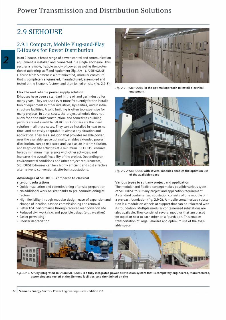
7/22/2019 Transmision y Distribucion Siemens
http://slidepdf.com/reader/full/transmision-y-distribucion-siemens 47/50
Power Transmission and Distribution Solutions
60 Siemens Energy Sector Power Engineering Guide Edition 7.0
Various types to suit any project and application
The modular and flexible concept makes possible various types
of SIEHOUSE to suit any project and application requirement.
A standard containerized substation consists of one module on
a pre-cast foundation (fig. 2.9-2). A mobile containerized substa-
tion is a module on wheels or support that can be relocated with
its foundation. Multiple modular containerized substations are
also available. They consist of several modules that are placed
on top of or next to each other on a foundation. This enables
transportation of large E-houses and optimum use of the avail-
able space.
2.9 SIEHOUSE
2.9.1 Compact, Mobile Plug-and-PlayE-Houses for Power Distribution
In an E-house, a broad range of power, control and communication
equipment is installed and connected in a single enclosure. This
secures a reliable, flexible supply of power, as well as the protec-
tion of operating staff and equipment (fig. 2.9-1). A SIEHOUSE
E-house from Siemens is a prefabricated, modular enclosure
that is completely engineered, manufactured, assembled and
tested at the Siemens factory, and then joined on site (fig. 2.9-3).
Flexible and reliable power supply solution
E-houses have been a standard in the oil and gas industry for
many years. They are used ever more frequently for the installa-
tion of equipment in other industries, by utilities, and in infra-
structure facilities. A solid building is often too expensive for
many projects. In other cases, the project schedule does not
allow for a site-built construction, and sometimes building
permits are not available. SIEHOUSE E-houses are the ideal
solution in all these cases. They can be installed in next to no
time, and are easily adaptable to almost any situation and
application. They are a solution that provides reliable power,
uses the available space optimally, enables extended power
distribution, can be relocated and used as an interim solution,
and keeps on site activities at a minimum. SIEHOUSE ensures
hereby minimum interference with other activities, and
increases the overall flexibility of the project. Depending on
environmental conditions and other project requirements,
SIEHOUSE E-houses can be a highly efficient and cost effective
alternative to conventional, site-built substations.
Advantages of SIEHOUSE compared to classical
site-built substations
Quick installation and commissioning after site preparation
No additional work on site thanks to pre-commissioning at
factory
High flexibility through modular design: ease of expansion and
change of location, fast de-commissioning and removal
Better HSE performance through reduced manpower on site
Reduced civil work risks and possible delays (e.g., weather)
Easier permitting
Shorter depreciation
Fig. 2.9-3: A fully integrated solution: SIEHOUSE is a fully integrated power distribution system that is completely engineered, manufactured,
assembled and tested at the Siemens facilities, and then joined on site
Fig. 2.9-1: SIEHOUSE ist the optimal approach to install e lectrical
equipment
Fig. 2.9-2: SIEHOUSE with several modules enables the optimum use
of the available space

7/22/2019 Transmision y Distribucion Siemens
http://slidepdf.com/reader/full/transmision-y-distribucion-siemens 48/50
Power Transmission and Distribution Solutions2.9 SIEHOUSE
61Siemens Energy Sector Power Engineering Guide Edition 7.0
2
2.9.2 Spot-on for a Broad Range of Applications
Customized solutions for individual project requirements
SIEHOUSE E-houses are designed with an eye to individual
requirements, and to all environmental as well as Health and
Safety Environment (HSE) conditions. All over the world, they
meet and exceed the requirements of the most ambitious proj-
ects and withstand harsh environmental conditions. Plus, proj-
ects that use E-houses suffer from fewer delays and construction
risks that are caused by the weather than projects that use
conventional brick buildings.
SIEHOUSE E-houses can be installed on raised platforms to
protect them from flooding. This also makes it possible to install
cable tray and bus duct systems under the E-house without
excavation. SIEHOUSE even reduces the need for additional
buildings, because facilities such as offices, battery rooms,
bathrooms and maintenance rooms can be included in an
E-house on request.
Resistant to environmental impact
In some industries, it is not enough to simply install electrical
equipment inside a building in order to protect it from external
influences. A number of reasons make it advisable to accommo-
date the equipment separately, for example, a high degree of
particles in the air, as well as potential dangers in case of direct
contact with hazardous environments and substances. In such
cases, SIEHOUSE E-houses are a simple, efficient and econom-
ical solution. The interlocking wall and roof panels are a barrier
against environmental influences. External particles are kept
outside thanks to HVAC overpressures. Enclosure integrity can
be enhanced with additional weatherproofing. The coating
provides outstanding resistance to chemicals, moisture and
abrasion. The enclosure can also be customized for extreme
ambient temperatures and humid environments. E-houses can
be designed for high wind speeds (up to 240 km/h), the use in
seismic zone 4, and high snow loads. Fireproof exterior walls
that protect switchgear from transformer failures are also
available. Special exterior finishes help match the E-houses to
its surroundings.
References in various fields of application
SIEHOUSE is employed in a multitude of situations related to:
Plant balancing for fossil and renewable energy Reliable power supply for critical power
Cost effective answer for space restricted application
Temporary power supplies
Power distribution system extension
Energy storage
Power electronics for power system application.
SIEHOUSE is also employed in a multitude of industries and
facilities. The fast and uncomplicated installation, as well as the
possibility to adapt them precisely to the individual application and
situation, makes them the most suitable option for a wide variety
of applications (fig. 2.9-4, fig. 2.9-5, fig. 2.9-6), especially in:
Oil and gas
Metal and mining industry
Data centers
Chemical industry
Automotive and aerospace
Food and beverage
Infrastructure
Utility power plants and substations.
Fig. 2.9-4: 19 SIEHOUSE E-houses to supply power for oil pipelines in
Colombia (ECOPETROL)
Fig. 2.9-6: SIEHOUSE in Lubbock (Texas) to power forced draft fans
at the generating power plant
Fig. 2.9-5: 3 split modules SIEHOUSE for Pearl GTL in Qatar, jointly
developed by QP and Shell
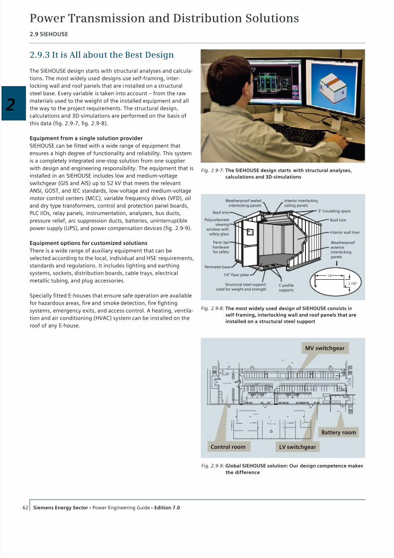
7/22/2019 Transmision y Distribucion Siemens
http://slidepdf.com/reader/full/transmision-y-distribucion-siemens 49/50
Power Transmission and Distribution Solutions2.9 SIEHOUSE
62 Siemens Energy Sector Power Engineering Guide Edition 7.0
2.9.3 It is All about the Best Design
The SIEHOUSE design starts with structural analyses and calcula-
tions. The most widely used designs use self-framing, inter-
locking wall and roof panels that are installed on a structural
steel base. Every variable is taken into account – from the raw
materials used to the weight of the installed equipment and all
the way to the project requirements. The structural design,
calculations and 3D-simulations are performed on the basis of
this data (fig. 2.9-7, fig. 2.9-8).
Equipment from a single solution provider
SIEHOUSE can be fitted with a wide range of equipment that
ensures a high degree of functionality and reliability. This system
is a completely integrated one-stop solution from one supplier
with design and engineering responsibility. The equipment that is
installed in an SIEHOUSE includes low and medium-voltage
switchgear (GIS and AIS) up to 52 kV that meets the relevant
ANSI, GOST, and IEC standards, low-voltage and medium-voltage
motor control centers (MCC), variable frequency drives (VFD), oil
and dry type transformers, control and protection panel boards,
PLC I/Os, relay panels, instrumentation, analyzers, bus ducts,
pressure relief, arc suppression ducts, batteries, uninterruptible
power supply (UPS), and power compensation devices (fig. 2.9-9).
Equipment options for customized solutions
There is a wide range of auxiliary equipment that can be
selected according to the local, individual and HSE requirements,
standards and regulations. It includes lighting and earthing
systems, sockets, distribution boards, cable trays, electrical
metallic tubing, and plug accessories.
Specially fitted E-houses that ensure safe operation are available
for hazardous areas, fire and smoke detection, fire fighting
systems, emergency exits, and access control. A heating, ventila-
tion and air conditioning (HVAC) system can be installed on the
roof of any E-house.
Fig. 2.9-7: The SIEHOUSE design starts with structural analyses,
calculations and 3D-simulations
MV switchgear
LV switchgear
Battery room
Control room
Fig. 2.9-9: Global SIEHOUSE solution: Our design competence makes
the difference
Weatherproof sealedinterlocking panels
Roof trim
Polycarbonateviewing
window withsafety glass
Panic barhardwarefor safety
1/4“ floor plate
Structural steel support;sized for weight and strength
C-profilesupports
Perimeter base
16“
2 7/8“
Weatherproofexteriorinterlockingpanels
Interior wall liner
Roof trim
3“ insulating space
Interior interlockingceiling panels
Fig. 2.9-8: The most widely used design of SIEHOUSE consists in
self-framing, interlocking wall and roof panels that are
installed on a structural steel support
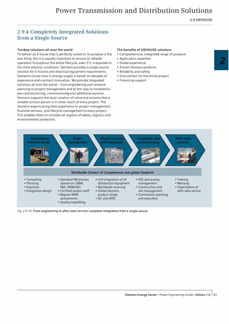
7/22/2019 Transmision y Distribucion Siemens
http://slidepdf.com/reader/full/transmision-y-distribucion-siemens 50/50
Power Transmission and Distribution Solutions2.9 SIEHOUSE
2
2.9.4 Completely Integrated Solutionsfrom a Single Source
Turnkey solutions all over the world
To deliver an E-house that is perfectly suited to its purpose is the
one thing. But it is equally important to ensure its reliable
operation throughout the entire lifecycle, even if it is exposed to
the most adverse conditions. Siemens provides a single-source
solution for E-houses and electrical equipment requirements.
Siemens’s know-how in energy supply is based on decades of
experience and constant innovation. We provide integrated
solutions all over the world – from engineering and network
planning to project management and all the way to installation,
pre-commissioning, commissioning and additional services.
Siemens supports the local creation of value and ensures that a
reliable contact person is in close reach of every project. The
Siemens experts bring their experience in project management,
financial services, and lifecycle management to every project.
This enables them to consider all aspects of safety, logistics and
environmental protection.
Fig. 2.9-10: From engineering to after sales service: complete integration from a single source
EngineeringNetwork design
Projectmanagement
Global sourcingand Integration
Installation andcommissioning
After salesservices
Worldwide Centers of Competences and global footprint
The benefits of SIEHOUSE solutions
Comprehensive, integrated range of products
Application expertise
Global experience
Proven Siemens products
Reliability and safety
One contact for the entire project
Financing support