


Idiomas
Páginas
Jurídico


ELEMENTOS DE MAQUINAS II
UNIV: JUAN CARLOS ALANOCA YUJRA
ENGRANAJES HELICOIDALESY CONICOS

ENGRANAJES
Transmiten movimiento rotacional
Transmiten grandes esfuerzos
Soportan sobre cargas bruscas
Transmisión de Potencia
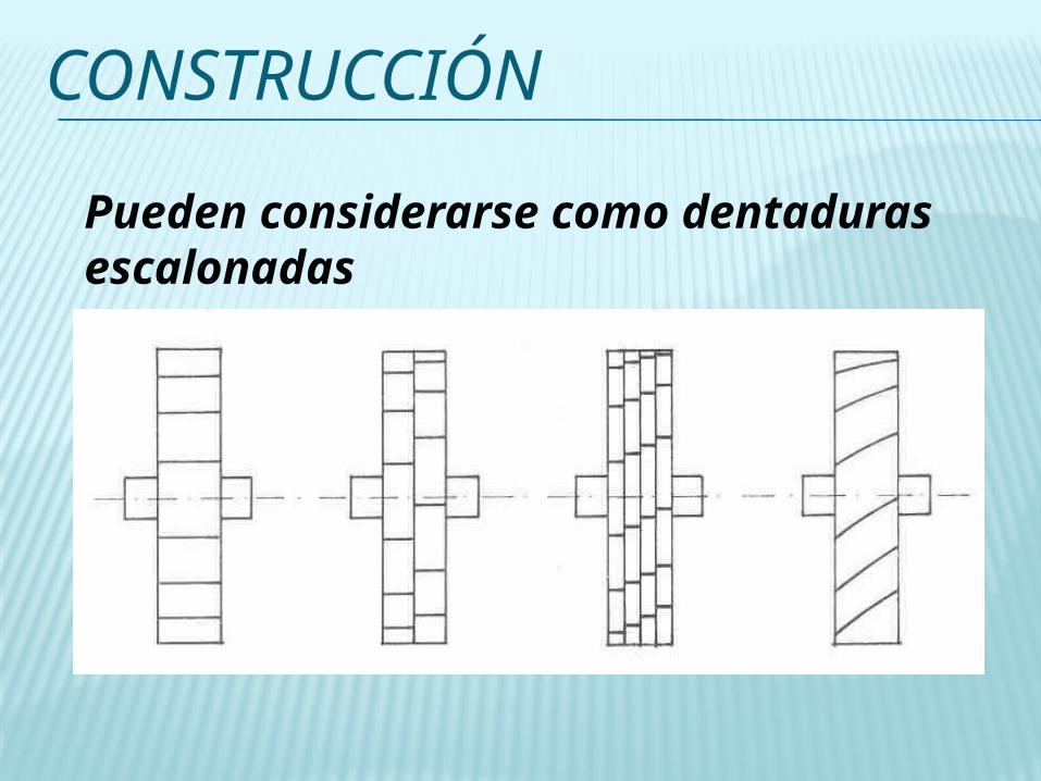
CONSTRUCCIÓN
Pueden considerarse como dentaduras escalonadas

CARACTERISTICAS GENERALES
El contacto de dientes es gradual
Reduce el ruido y las cargas dinámicas
Transmite una mayor potencia
Aumenta la velocidad
Incrementa la relación de transmisión

CLASIFICACIÓN
a) ejes paralelos b) ejes oblicuos c) ejes perpendiculares

• Diámetro medio: D= ma z• Diámetro de cabeza: D= ma (z+2)• Diámetro de fondo: D= ma (z-2,5)
DIMENSIONES:
Valores Caracteristicos:
® Número de dientes, z® Módulo, m en mm® Paso= m® a, ángulo de hélice. Valores habituales de 15º 20º
RUEDAS HELICOIDALES
Módulo aparente:ma = m / cos a

RUEDA HELICOIDAL
Figure 14.25 Helical gear. (a) Front view; (b) side view.
Text Reference: Figure 14.25, page 651

FUERZAS SOBRE EL DIENTE
Figure 14.20 Forces acting on individual gear tooth.
Text Reference: Figure 14.20, page 640

RUEDAS HELICOIDALES
FUERZAS GENERADASFuerza Tangencial:
Ft = Mt / Ra
Fuerza Radial:
Fr = Ft Tg a
Tg a = Tg / Cos a
Fuerza axial:
Fr = Ft Tg a
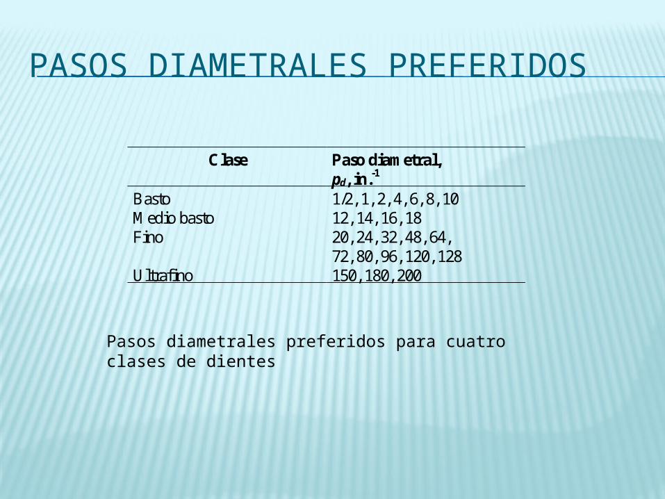
PASOS DIAMETRALES PREFERIDOS
Pasos diametrales preferidos para cuatro clases de dientes
Clase Paso diametral, pd, in.-1
Basto 1/2, 1, 2, 4, 6, 8, 10 Medio basto 12, 14, 16, 18 Fino 20, 24, 32, 48, 64,
72, 80, 96, 120, 128 Ultrafino 150, 180, 200

PASOS DIAMETRALES
Pasos diametrales estándares comparados con el tamaño del diente. Se supone un tamaño real

ADDENDUM, DEDENDUM Y SEPARACION
Parameter Symbol Coarse Pitch(pd<20in-1)
Fine pitch(pd 20in-1)
Metric modulesystem
Addendum a 1/ pd 1/ pd 1.00 mDedendum b 1.25/ pd 1.200/ pd+0.002 1.25 mClearance c 0.25/ pd 0.200/ pd+0.002 0.25 m
Table 14.2 Formulas for addendum, dedendum, and clearance (pressure angle 20°, full-depth involute.)
Text Reference: Table 14.2, page 623
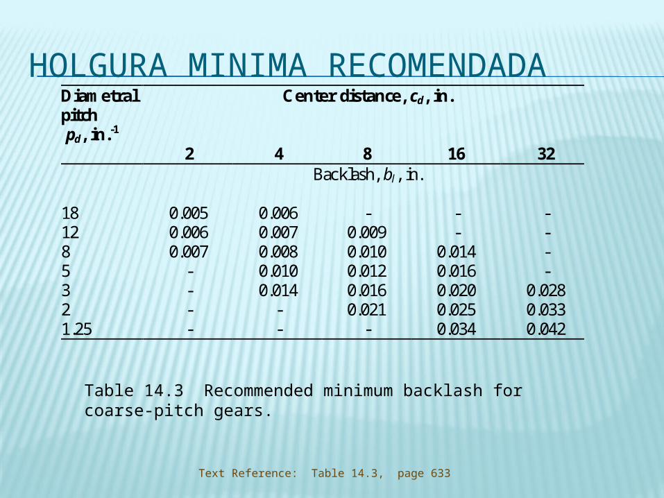
HOLGURA MINIMA RECOMENDADADiametralpitch pd, in.-1
Center distance, cd, in.
2 4 8 16 32Backlash, bl, in.
181285321.25
0.0050.0060.007
----
0.0060.0070.0080.0100.014
--
-0.0090.0100.0120.0160.021
-
--
0.0140.0160.0200.0250.034
----
0.0280.0330.042
Table 14.3 Recommended minimum backlash for coarse-pitch gears.
Text Reference: Table 14.3, page 633

ENGRANAJES CILINDRICOS INTERNOS
Figure 14.14 Internally meshing spur gears.
Text Reference: Figure 14.14, page 635

ESFUERZO DE FLEXION VS DUREZA BRINELL
Figure 14.18 Effect of Brinell hardness on allowable bending stress for two grades of through-hardened steel [ANSI/AGMA Standard 1012-F90, Gear Nomenclature, Definition of Terms with Symbols, American Gear Manufacturing Association, 1990.]
Text Reference: Figure 14.18, page 638

CONTACT STRESS VS. BRINELL HARDNESS
Figure 14.19 Effect of Brinell Hardness on allowable contact stress for two grades of through-hardened steel. [ANSI/AGMA Standard 1012-F90, Gear Nomenclature, Definition of Terms with Symbols, American Gear Manufacturing Association, 1990.]
Text Reference: Figure 14.19, page 639

FACTOR GEOMETRICO
Figure 14.22 Spur gear geometry factors for pressure angle of 20° and full-depth involute. [ANSI/AGMA Standard 1012-F90, Gear Nomenclature, Definition of Terms with Symbols, American Gear Manufacturing Association, 1990.]
Text Reference: Figure 14.21, page 643

FACTOR DE APLICACIONDriven Machines
Power Source Uniform Light shock Moderate shock Heavy shockApplication factor, Ka
UniformLight shockModerate shock
1.001.201.30
1.251.401.70
1.501.752.00
1.752.252.75
Table 14.5 Application factor as a function of driving power source and driven machine.
Text Reference: Table 14.5, page 643

FACTOR DE TAMAÑO
Diametral pitch pd,in.-1
Module, m,mm
Size factor, Ks
5433
1.25
568
1220
1.001.051.151.251.40
Table 14.6 Size factor as a function of diametral pitch or module.
Text Reference: Table 14.6, page 644
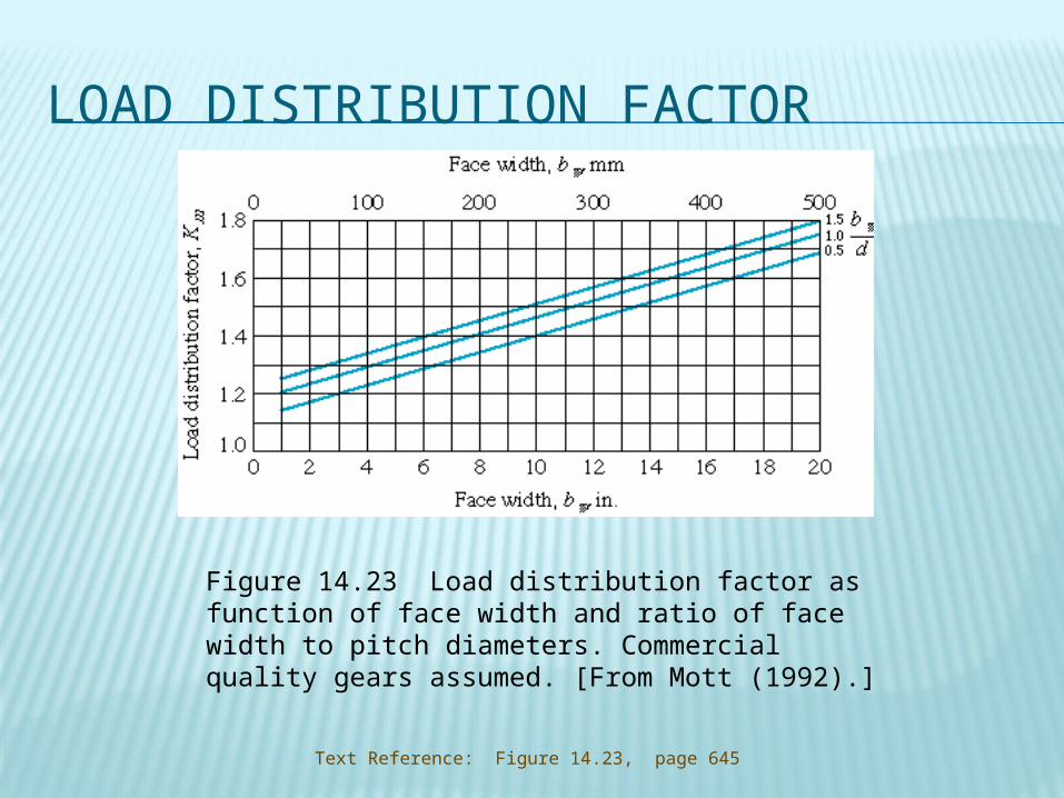
LOAD DISTRIBUTION FACTOR
Figure 14.23 Load distribution factor as function of face width and ratio of face width to pitch diameters. Commercial quality gears assumed. [From Mott (1992).]
Text Reference: Figure 14.23, page 645

DYNAMIC FACTOR
Text Reference: Figure 14.24, page 645
Figure 14.24 Dynamic factor as function of pitch-line velocity and transmission accuracy level number.
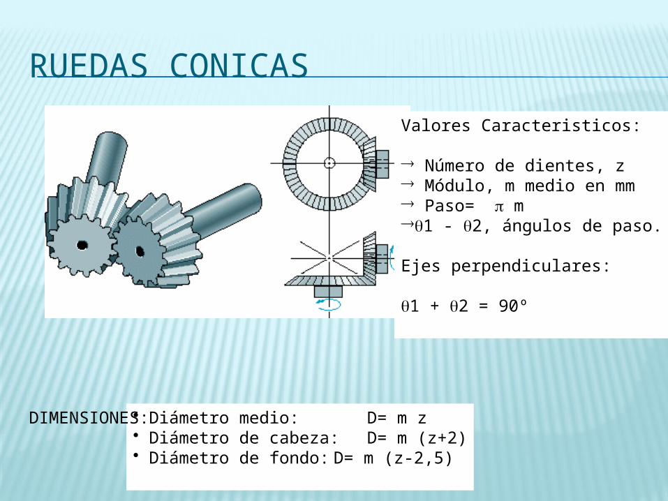
RUEDAS CONICAS
Valores Caracteristicos:
® Número de dientes, z® Módulo, m medio en mm® Paso= m®1 - 2, ángulos de paso.
Ejes perpendiculares:
1 + 2 = 90º
• Diámetro medio: D= m z• Diámetro de cabeza: D= m (z+2)• Diámetro de fondo: D= m (z-2,5)
DIMENSIONES:
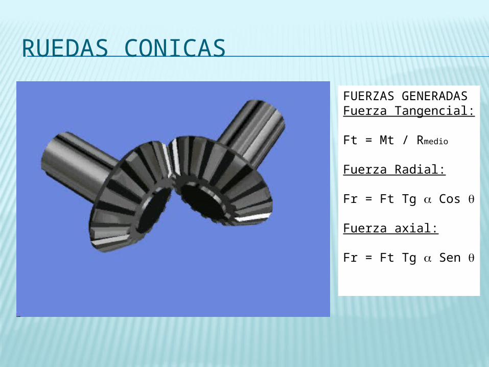
RUEDAS CONICAS
FUERZAS GENERADASFuerza Tangencial:
Ft = Mt / Rmedio
Fuerza Radial:
Fr = Ft Tg Cos
Fuerza axial:
Fr = Ft Tg Sen
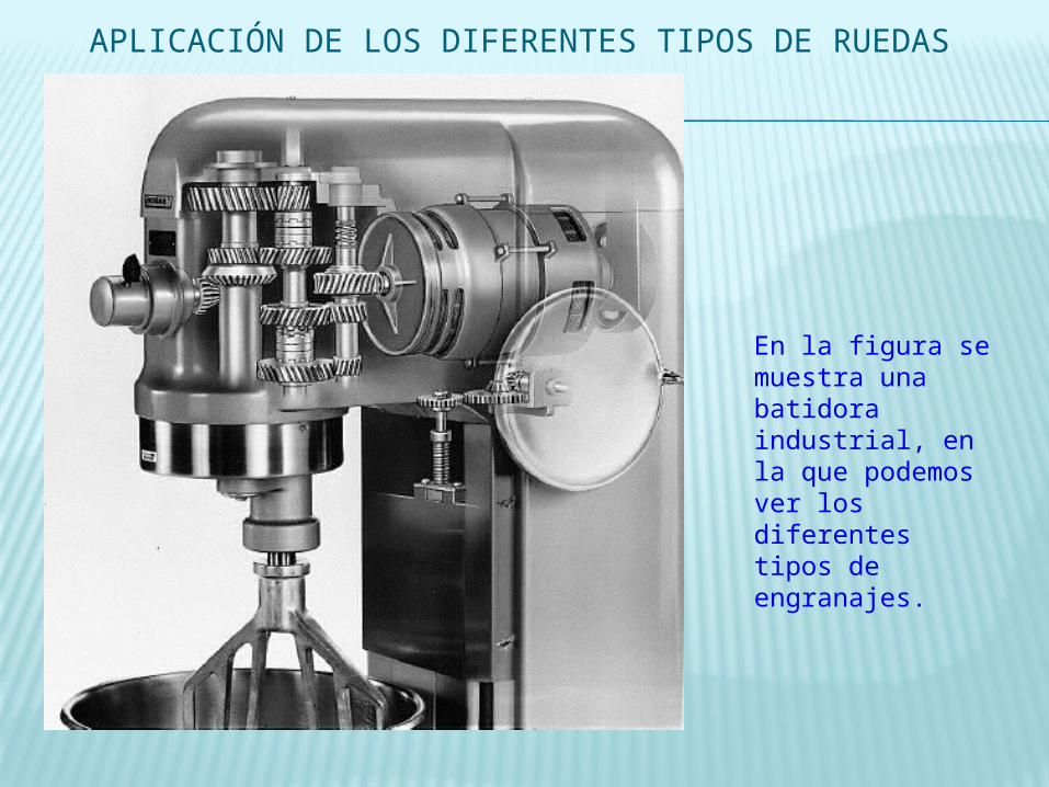
En la figura se muestra una batidora industrial, en la que podemos ver los diferentes tipos de engranajes.
APLICACIÓN DE LOS DIFERENTES TIPOS DE RUEDAS

ENGRANAJE, TORNILLO SIN FÍN
a.) de dientes cilíndricos b.) doble envolvente.
Top Related