Copia de Presentacion
80
Schlumberger Private SMS– Slide 1 Sand Management Services Victor Chipana Sand Control - SLB
-
Upload
alejandro-calvimontes -
Category
Documents
-
view
15 -
download
0
Transcript of Copia de Presentacion

Sch
lum
berg
er P
rivate
SMS– Slide 1
Sand Management Services
Victor Chipana
Sand Control - SLB
Sch
lum
berg
er P
rivate
SMS– Slide 2
Outline• Process Management• Formation Characteristics• Factors & Causes of Sand Production• Reasons for Sand Control

Sch
lum
berg
er P
rivate
SMS– Slide 3
Fundamental Cause of Sand Production
• Destabilizing forces overcome formation strength – formation matrix fails– if sand is mobile - sand transport
(production) will occur– sand production is a function of rock
strength and/or fluid flow effectsStage 1 - Failure Stage 2 - Transportation

Sch
lum
berg
er P
rivate
SMS– Slide 4
General Formation CharacteristicsFive general types of sand producing
formation:
1. No sand – no fines– Competent formation
2. Fines migration– Generally acceptable– Must be manageable

Sch
lum
berg
er P
rivate
SMS– Slide 5
General Formation Characteristics3. Some sand production
– Unconsolidated formation.4. High sand production
– Loss of perforation tunnel and formation integrity.
5. Major sand production– Formation collapse, reservoir settling.

Sch
lum
berg
er P
rivate
SMS– Slide 6
Formation Hardness ClassificationDescription Sonic Travel
Time Brinell
Hardness Strength, Analogue
Unconsolidated >140 msec? <2 Near 0 psi. Similar to strength required for sand castles. Sonic travel times may not accurately predict this state.
Semi or marginally Consolidated
>120 msec 2 to 5 <300 psi, easily crushed with fingers.
Friable
>90<120 msec 5 to 10 300 to 1000 psi, crushed with forceps.
Consolidated
>50<90 msec 10 to 30 1000 to 5000 psi, stable, but may loose strength as rock dries.
Hard
<50 msec 30 to >100 5000 to over 35,000 psi, does not change significantly.
Sch
lum
berg
er P
rivate
SMS– Slide 7
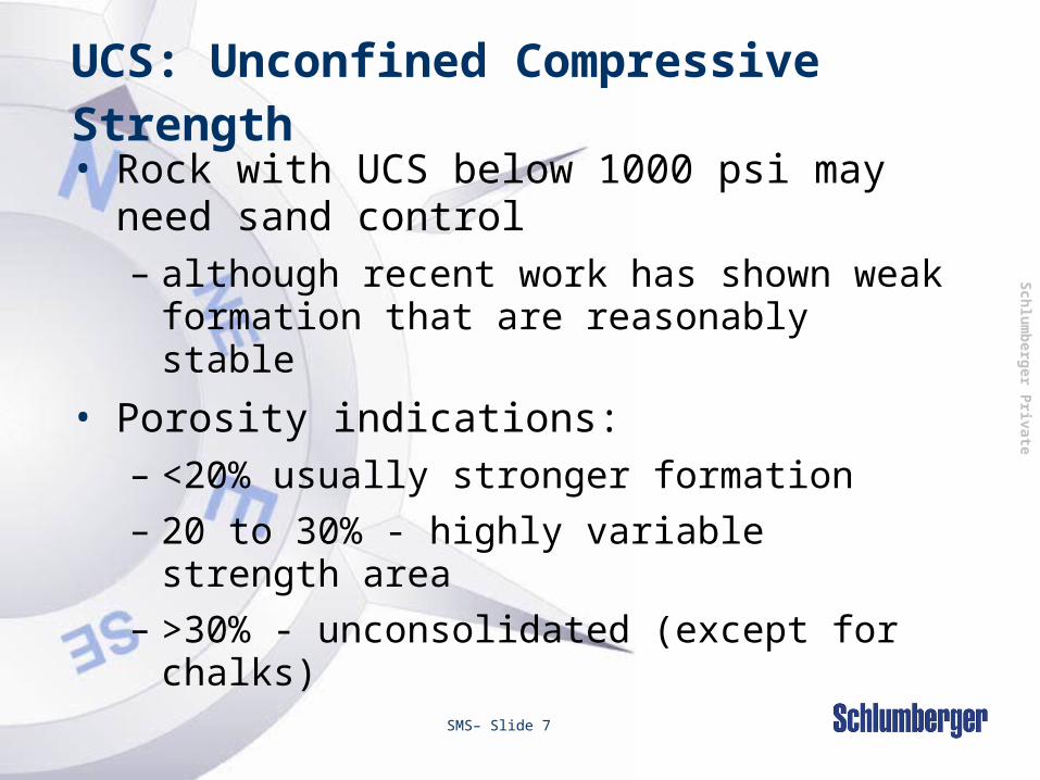
UCS: Unconfined Compressive Strength• Rock with UCS below 1000 psi may need
sand control – although recent work has shown weak
formation that are reasonably stable
• Porosity indications: – <20% usually stronger formation– 20 to 30% - highly variable strength area– >30% - unconsolidated (except for
chalks)

Sch
lum
berg
er P
rivate
Factors for Sand Production
Formation or reservoir factors:• Rock mechanics
– overburden, intergranular friction, differential stresses
• Formation lithology– cementing material and degree of
consolidation– particle size, shape and distribution
• Reservoir fluid characteristics– viscosity, velocity and resultant drag forces
(friction)– changes in surface wetting
•Drag Forces •Cementing•Capillary•Overburden

Sch
lum
berg
er P
rivate
SMS– Slide 9
Factors for Sand Production
Production characteristics• Water breakthrough
– coning or injection breakthrough
• Structural weakening by reactive fluids– dissolution of cementing material
• Frequency of production shutdowns

Sch
lum
berg
er P
rivate
SMS– Slide 10
New Well - Formation Strength Factors• Poorly consolidated formation
– generally a “young sandstone problem”
Epoch Period Era Eon
Phanerozoic
Proterozoic
Cenozoic
Mesozoic
Paleozoic
RecentPleistocene
PlioceneMiocene
OligoceneEocene
Paleocene
Quaternary
Tertiary
CretaceousJ urassicTriassicPermian
CarboniferousDevonian
OrdovicianSilurian
Cambrian
00.011.65.324375766
144208245286360408438505570
Epoch Period Era Eon
Phanerozoic
Proterozoic
Cenozoic
Mesozoic
Paleozoic
RecentPleistocene
PlioceneMiocene
OligoceneEocene
Paleocene
Quaternary
Tertiary
CretaceousJ urassicTriassicPermian
CarboniferousDevonian
OrdovicianSilurian
Cambrian
00.011.65.324375766
144208245286360408438505570
Sand production difficulties most commonly are
associated with Tertiary
sandstones

Sch
lum
berg
er P
rivate
SMS– Slide 11
Old Well - Production Factors
• Increased water cut – water coning or injection break-through– reducing stability of perforation arch– higher drag forces
Water break through can effect the performance
of the formation cementing material or
change the flow characteristics which
destabilises the formation sand
Sch
lum
berg
er P
rivate
SMS– Slide 12
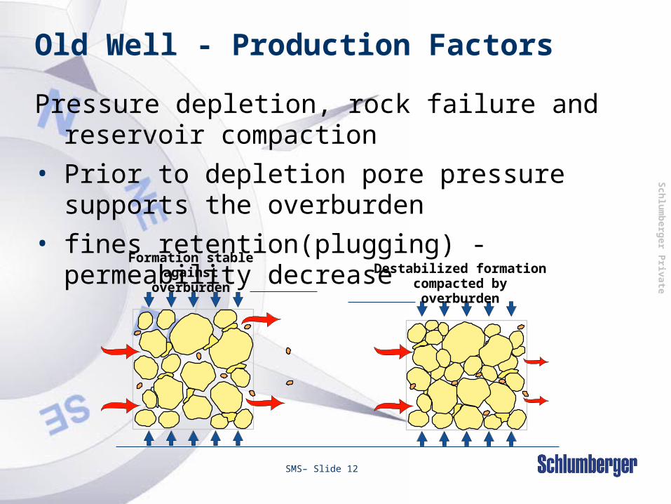
Old Well - Production Factors
Pressure depletion, rock failure and reservoir compaction
• Prior to depletion pore pressure supports the overburden
• fines retention(plugging) - permeability decrease
Formation stable against
overburdenDestabilized formation
compacted by overburden
Sch
lum
berg
er P
rivate
SMS– Slide 13
Causes of Sand Production
• Once the destabilizing forces overcome the formation strength, the rock will fail.
• Sand production will follow if sand can be transported.
Sch
lum
berg
er P
rivate
SMS– Slide 14
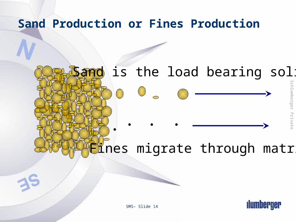
Sand Production or Fines Production
Fines migrate through matrix
Sand is the load bearing solids.

Sch
lum
berg
er P
rivate
SMS– Slide 15
Why Control Sand Production?Reasons for controlling sand production:• Produced sand disposal • Formation stability• Equipment erosion• Realizing full well productivity
Sch
lum
berg
er P
rivate
SMS– Slide 16
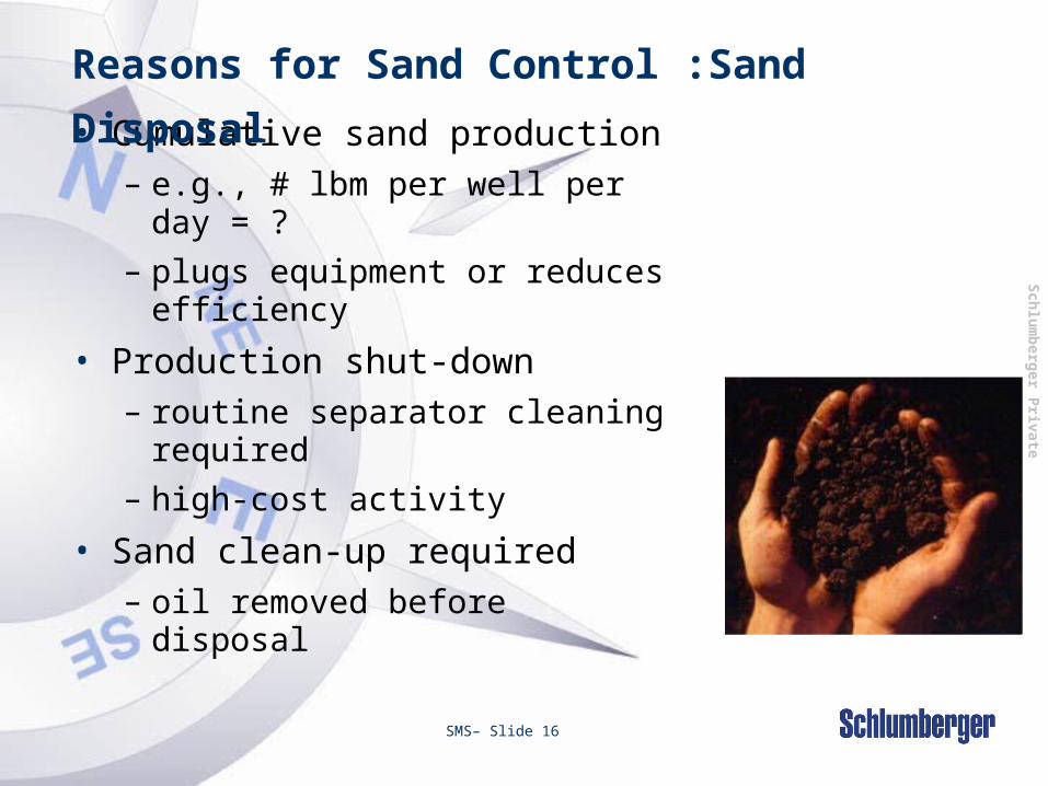
• Cumulative sand production– e.g., # lbm per well per day
= ?– plugs equipment or reduces
efficiency
• Production shut-down– routine separator cleaning
required– high-cost activity
• Sand clean-up required– oil removed before disposal
Reasons for Sand Control :Sand
Disposal

Sch
lum
berg
er P
rivate
SMS– Slide 17
Reasons for Sand Control: Casing /
Liner Collapse• Failure may occur
due to :– Non uniform lateral
loading as rock is produced.
– High axial compressive load due to slumping of the overlying casing-bearing formation.

Sch
lum
berg
er P
rivate
SMS– Slide 18
Reasons for Sand Control: Sand
Erosion• Sand production can cause erosion in both
surface and downhole equipment such as :
Downhole Surface
Blast Joints Chokes
Gas lift Equipment Elbows / Tees
Pumps Metering Devices
Safety Valves Flow line
Circulating sleeves Flanges
Nipples Wellhead
Tubular Valves

Sch
lum
berg
er P
rivate
SMS– Slide 19
Reasons for sand control :Well ProductivityAs a stimulation treatment option:
– Sandface completions can enable a well to produce at or near full potential while avoiding sanding problems.
A properly completed well will:– Enable higher production rates to be
safely achieved.– Retain formation stability at higher
drawdown pressures.

Sch
lum
berg
er P
rivate
Sanding MechanismsKey points:• Sandface completions relate to the control
of the load bearing solids within the formation structure– some fine production occurs from most wells– production of fines may not be a problem
• Sand production is a function of:– formation characteristics– fluid flow conditions (flow rate and
drawdown)– produced fluids

Sch
lum
berg
er P
rivate
SMS– Slide 21
What is Gravel Pack?
Consists of sized
particles placed in
the annular space
between an
unconsolidated
formation and a
centralized
screen.
Open ( EGP)or
cased hole ( IGP).

Sch
lum
berg
er P
rivate
SMS– Slide 22
Typical Gravel Pack Completion ( IGP)
Packer
Tubing
Blank Pipe
Sump Packer
Proppant(gravel)
Casing
Seal Assembly

Sch
lum
berg
er P
rivate
Horizontal Open Hole Gravel PackingTwo main placement techniques:• Water packing
– brine carrier, high rate, low concentration– sustained circulation required during job
• Alternate path– viscous carrier, low rate, high
concentration– sustained circulation not required

Sch
lum
berg
er P
rivate
SMS– Slide 24
Fracturing
StimPAC
Gravel Pack

Sch
lum
berg
er P
rivate
SMS– Slide 25
Gravel Placement Methods• Gravel Pack
– 1-5 BPM - pumping brine with low concentration gravel. Typically (1 to 2 PPA).
– Treatment pressure below fracture pressure.• High Rate Water Pack (HRWP) & GelPACs
– Treatment rate above 5 bpm • Pumping brine with low concentration gravel.
Typically (1 to 2 PPA).( HRWP’s) .• Pumping viscous fluid with high concentration gravel.
Typically (4 to 8 PPA).( GelPACKS) .– Treatment pressure may reach fracture pressure in lower
permeability or highly damaged wells.• Frac-n-Pack or StimPAC
– 5 to 40 BPM - pumping viscous fluid with “ramped” concentration gravel. Typically (0.5 - 15 PPA)
– High Rates Erosion, Burst , Collapse (Stronger Equipment Required).

Sch
lum
berg
er P
rivate
SMS– Slide 26
PPA
Pound of Proppant per gallon Added (PPA)
• Volume that the proppant occupies is given by:
• Total volume is given by: 1 gallon +: Absolute proppant
density [ppg]
=
+
Sch
lum
berg
er P
rivate
SMS– Slide 27
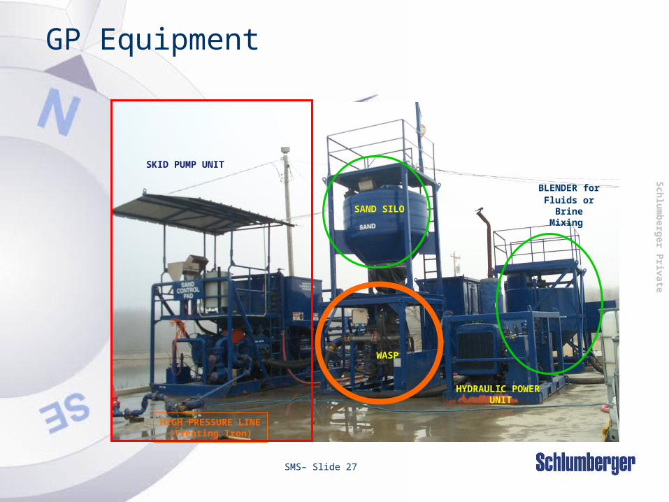
GP Equipment
SKID PUMP UNIT
WASP
HIGH PRESSURE LINE(Treating Iron)
SAND SILO
HYDRAULIC POWER UNIT
BLENDER for
Fluids or Brine
Mixing

Sch
lum
berg
er P
rivate
SMS– Slide 28
Sand Silo
HOSE FEEDING FLUID (4-in)
Two 4-in Hoses to Triplex
•4-in Manifold on TriplexHas a densitometer for gravel conc.•Max. Rate w/WASP’s C-PUMP ~ 5 bpm•1 Hose for recirculation if C-Pump is pumping at rates higher than treatment (Triplex) rate
Go to
Equipment
Set Up
Sch
lum
berg
er P
rivate
SMS– Slide 29
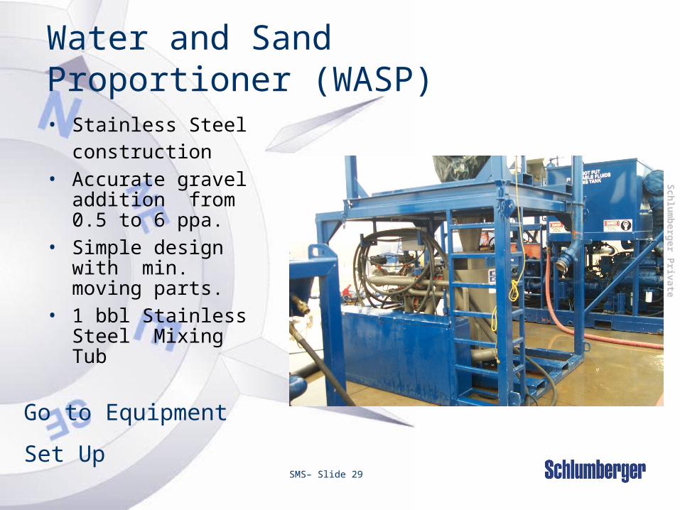
Water and Sand Proportioner (WASP)• Stainless Steel
construction• Accurate gravel
addition from 0.5 to 6 ppa.
• Simple design with min. moving parts.
• 1 bbl Stainless Steel Mixing Tub
Go to Equipment
Set Up

Sch
lum
berg
er P
rivate
SMS– Slide 30
WASP - Rig-Up
Water / BrineDownhole
Slurry
Gravel

Sch
lum
berg
er P
rivate
SMS– Slide 31
Barge Operations
35 BPM13,500 psi700K lbs Prop

Sch
lum
berg
er P
rivate
SMS– Slide 32
Slotted Pipe

Sch
lum
berg
er P
rivate
SMS– Slide 33
Slotted Pipe
• Applications :– Standalone screen for open hole
• Advantage :– Fixed gap– Cost
• Disadvantage :– Low open area– Erosion and plugging resistance

Sch
lum
berg
er P
rivate
SMS– Slide 34
Wire-wrap Screen
• A single wire rolled around a perforated base pipe with a fixed gap opening
• Slip-on type• Wrap on pipe type
Perforated base pipe
Wrap wire
Rib wire
Controlled gap

Sch
lum
berg
er P
rivate
SMS– Slide 35
Wire-wrap Screen
• Applications :– Cased and open hole gravel pack– Stand alone screen for open hole
• Advantage :– Fixed gap– Cost– Heavy duty application
• Disadvantage :– Plugging and erosion in standalone application

Sch
lum
berg
er P
rivate
SMS– Slide 36
Pre-pack Screen
• Two concentric wire wraps with gravel placed in the annular space
• The thickness of the gravel layer can be varied to meet special needs
• May be subject to plugging• Offers a redundant sand
retention method

Sch
lum
berg
er P
rivate
SMS– Slide 37
Pre-pack Screen
• Type of gravel :– Dry gravel (12/20, 20/40, 16/30,…)– Resin Coated Gravel
Outer jacket
Pre-packed gravel
Inner jacket
Perforated base pipe

Sch
lum
berg
er P
rivate
Plugging of PPS in unsupported wellbore
Screen FormationGravel Fines
Permeability reducing fines, which have been produced from wellbore collapse

Sch
lum
berg
er P
rivate
SMS– Slide 39
Pre-pack Screen
• Application :– Cased and open hole gravel pack– Standalone screen for open hole
• Advantage :– Redundancy for a void in gravel pack
• Disadvantage :– Plugging– Increased OD

Sch
lum
berg
er P
rivate
SMS– Slide 40
Mesh Type Screen
Woven Wire MeshPorous Metal Fiber Stainless Steel Wool Stabilization Bed
• Use a number of layers of woven wire mesh that form a filter designed to retain formation sand
• Size measured in micron (from 60 to 250 micron)
Sch
lum
berg
er P
rivate
SMS– Slide 41
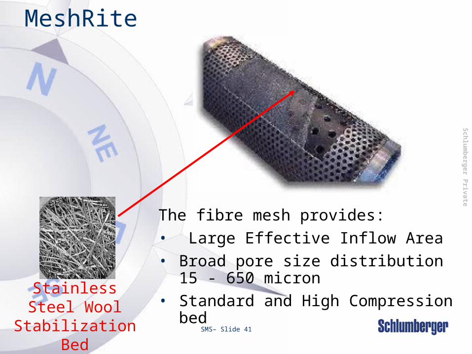
MeshRite
Stainless Steel Wool
Stabilization Bed
The fibre mesh provides:• Large Effective Inflow Area • Broad pore size distribution 15 - 650
micron• Standard and High Compression
bed

Sch
lum
berg
er P
rivate
SMS– Slide 42
STAR Screen
• Final assembly is flush.• Cartridges are integral to base pipe.• Require thicker/heavier base pipe.
Sch
lum
berg
er P
rivate
SMS– Slide 43
Mesh Type Screen
• Application :– Open hole gravel pack– Stand alone screen for cased and open
hole
• Advantage :– Plugging resistance
• Disadvantage :– No fixed gap (requires high quality
control)

Sch
lum
berg
er P
rivate
SMS– Slide 44
Expandable Screen
ExpandableBase Pipe
Attach filtersonto base pipe
ExpandableBase Pipe
FiltrationMedia
ExpandableShroud
Sch
lum
berg
er P
rivate
SMS– Slide 45
Expandable Screen
• Applications :– Open hole– Cased Hole
• Advantage :– Increased OD/ID ratio– Wellbore stabilization
• Disadvantage :– Cost– Collapse resistance

Sch
lum
berg
er P
rivate
SMS– Slide 46
Features on Screen
• Alternate Path Technology :– Schlumberger has exclusive license
Transport tubes
Packing tubes

Sch
lum
berg
er P
rivate
SMS– Slide 47
Features on Screen
• Fiber Optics
• Inflow Control Device for long horizontal open hole completed with standalone screen
Sch
lum
berg
er P
rivate
SMS– Slide 48
Screen Considerations
• Inflow area (screen and base pipe)• Pack thickness• Gravel placement (O.D)• Clearance
– Fishing– Dogleg severity/Installation
• ID for logging, selective equipment or productivity
• Screen nominal size is the screen base pipe OD
• Thread type and screen mechanical properties

Sch
lum
berg
er P
rivate
SMS– Slide 49
Screen Failure
Erosion during pumping
Remedial TreatmentsFlapper not hold or poor filtration on Injection well
Incomplete Perforation Packing
Tensile failure
High drawdown and plugging

Sch
lum
berg
er P
rivate
SMS– Slide 50
Formation Sampling
The first step to select screen or gravel to retain the
sand
is to obtain representative samples of formation sand.
Full Core.- (If possible 2-3 ft within the
formation)
Side Wall Core (wireline)
Produced Sand (fine grains)
Bailed Sand (coarse grains)

Sch
lum
berg
er P
rivate
SMS– Slide 51
Sand Size AnalysisParticle Size Measurement
• Sieving
– Very fine particles can adhere to the larger particles and agglomerate underestimation of the fines in the analysis.
– Sieving analysis can only measure down to 44 microns.
– Result of sieving analysis is reported as the accumulative weight vs the particle size.
Sch
lum
berg
er P
rivate
SMS– Slide 52
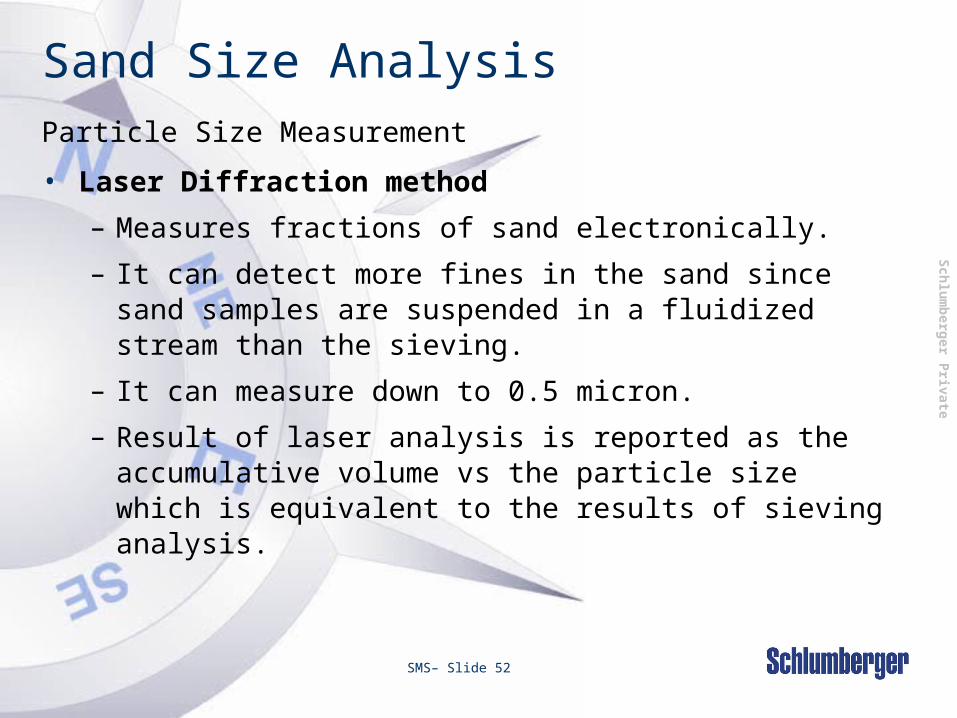
Particle Size Measurement
• Laser Diffraction method
– Measures fractions of sand electronically.
– It can detect more fines in the sand since sand samples are suspended in a fluidized stream than the sieving.
– It can measure down to 0.5 micron.
– Result of laser analysis is reported as the accumulative volume vs the particle size which is equivalent to the results of sieving analysis.
Sand Size Analysis

Sch
lum
berg
er P
rivate
SMS– Slide 53
Cumulative Log Diagram (S-Plot)
or PSD Graph
US Sieve Weight Cumulative
number retained % %70 0.08 1.38 1.38100 0.43 7.43 8.81140 0.79 13.64 22.45
200 1.21 20.90 43.35270 1.29 22.29 65.64325 0.57 9.84 75.48400pan 1.42 24.52 100.00
Total 5.79 gr.

Sch
lum
berg
er P
rivate
SMS– Slide 54
Formation Analysis - Cumulative PSD
Cumulative Log Diagram
0%
20%
40%
60%
80%
100%
0.0010.0100.100Grain Diameter (inches)
Sample A Sample B
Cu
m.
% b
y W
eig
ht

Sch
lum
berg
er P
rivate
Cumulative Log Diagram (S-Plot)
100 90 80 70 60 50 40 30 20 10 0
8 12 16 20 30 40 50 70 100 140 200 270 325 400 pan
Grain Size (in)o
o
o
o
o
o
o
D 50
D 40
D 90
D 95
D 10

Sch
lum
berg
er P
rivate
SMS– Slide 56
Definitions on PSD
• From Tiffin et al., SPE 39437
• Fines are defined as < 325 mesh (44 m) particles
• Uniformity Coefficient = D40/D90
– Well-sorted formations have low values for D40/D90
• Very uniform sand: D40/D90 = 1.3 to 1.5
• Well-sorted formation: D40/D90 < 3
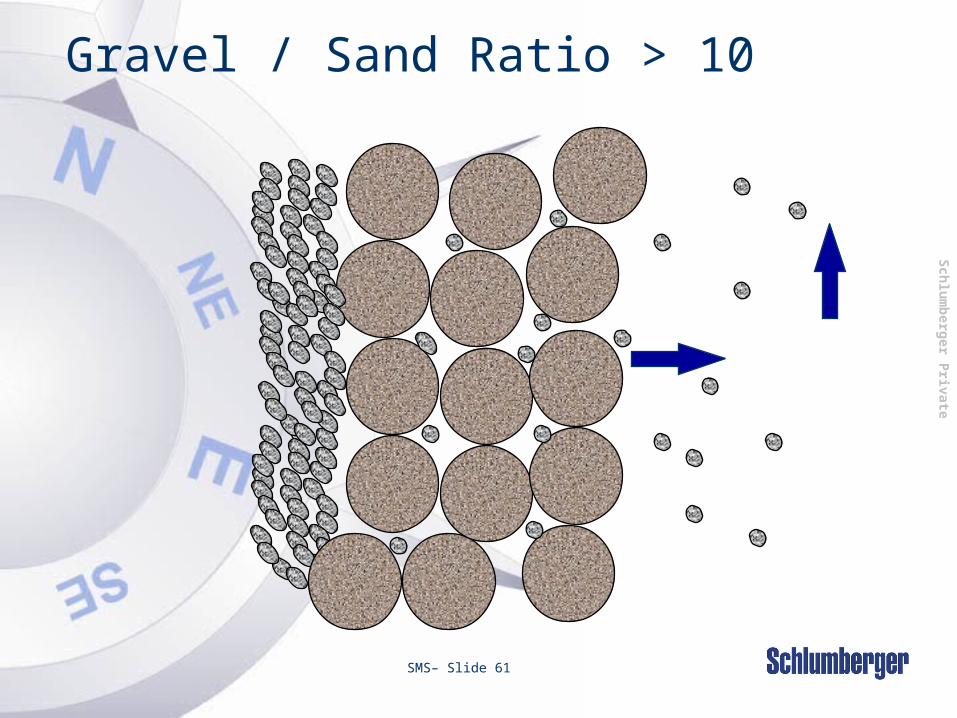
• Poorly-sorted formation: D40/D90 ~ 10
• Sorting Coefficient = D10/D95
– Very sensitive to fines content

Sch
lum
berg
er P
rivate
SMS– Slide 57
Formation Fines
• Small weight % of fines translates into an alarming number of particles
• Problems start with only 5% of fines in a typical formation
• Best candidates for SAS completions have a fines content ~ 2%

Sch
lum
berg
er P
rivate
SMS– Slide 58
Gravel Pack Sizing
Sand Gravel
•Gravel size(Dg50) vs Sand size(Ds50)

Sch
lum
berg
er P
rivate
SMS– Slide 59
Gravel / Sand Ratio < 6

Sch
lum
berg
er P
rivate
SMS– Slide 60
Gravel / Sand Ratio 6 - 10
Sch
lum
berg
er P
rivate
SMS– Slide 61
Gravel / Sand Ratio > 10

Sch
lum
berg
er P
rivate
SMS– Slide 62
Gravel Permeability Comparisons
In situ Gravel Permeability (Zero Closure Stress)
US Sieve Number Range
Description PermeabilityMillidarcies
50/70 Resieved Sand 30,000
40/60 Resieved Sand 45,000
30/50 Ceramic (“EconoProp”)
230,000
20/40 Resieved Sand 120,000
20/40 Ceramic (“EconoProp”)
340,000
20/40 Ceramic (“CarboLite”’)
540,000
Man made proppants have 300-500% more permeability
Sch
lum
berg
er P
rivate
SMS– Slide 63
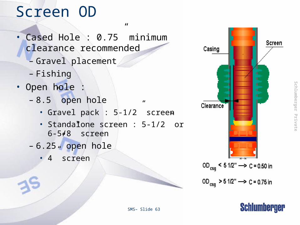
Screen OD
• Cased Hole : 0.75” minimum clearance recommended– Gravel placement– Fishing
• Open hole :– 8.5” open hole
• Gravel pack : 5-1/2” screen
• Standalone screen : 5-1/2” or 6-5/8” screen
– 6.25” open hole• 4” screen

Sch
lum
berg
er P
rivate
Gravel Volumes
• Practical guidelines based strictly on experience :
• Use annular volume of screens and blank plus :
– New zones
Good clean formations 0.25 cu.ft/ ft. perfs
Dirty, low perm formations 0.25 - 0.5 cu.ft/ ft. perfs
– Re-completions 0.5 - 1.5 cuft / ft.
perfs
(zones have produced sand)

Sch
lum
berg
er P
rivate
SMS– Slide 65
Absolute and Bulk Density• Absolute density of a gravel is the density of the
grain and is given by:
I.e: Pacsan: SG = 2.65 , 22.1 ppgIsopac: SG = 1.60 , 13.3 ppg
• Bulk density of a gravel is the density of the bulk that includes the air between grains and is given by:
I.e: Pacsan: 13.3 -14.3 ppg = 99 - 107 #/ft3
Isopac: 7.6 - 8.6 ppg = 59 - 64 #/ft3

Sch
lum
berg
er P
rivate
SMS– Slide 66
PPA and Yield
Pound of Proppant per gallon Added (PPA)
• Volume that the proppant occupies is given by:
• Total volume is given by: 1 gallon +: Absolute proppant
density [ppg]
=
+
Sch
lum
berg
er P
rivate
SMS– Slide 67
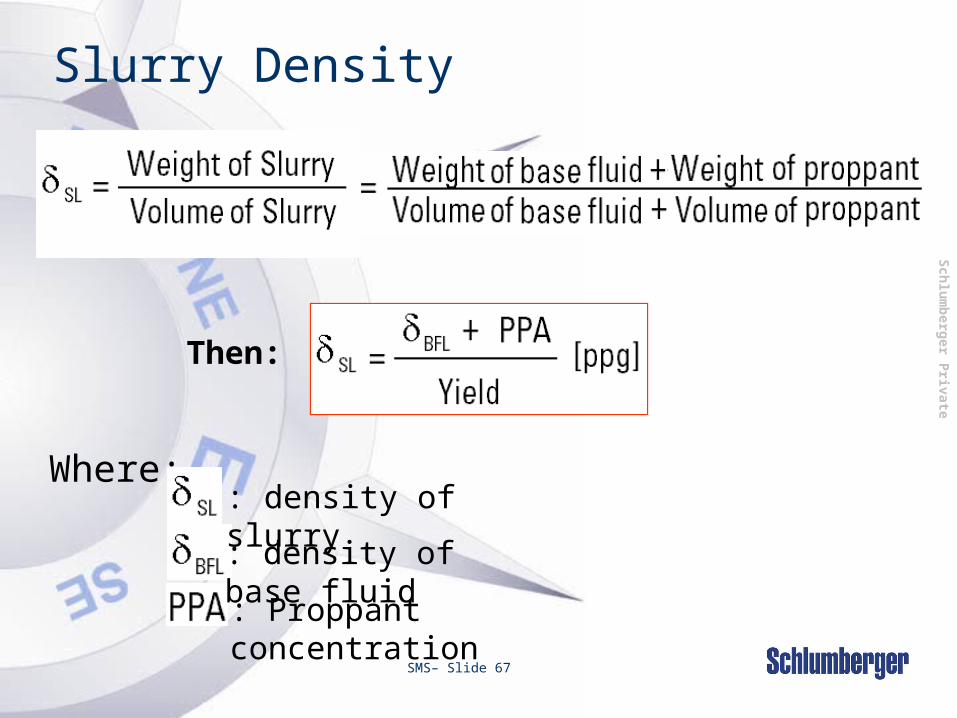
Slurry Density
Then:
Where:: density of slurry: density of base fluid: Proppant concentration

Sch
lum
berg
er P
rivate
SMS– Slide 68
Slurry density calculation
Example:Calculate the slurry density in ppg when 8
pounds of Pacsan are added to 1 gal of 9.6 ppg brine.

Sch
lum
berg
er P
rivate
Gravel Pack Calculations
1. Blank / Casing annular volume [ft3]
100% or less of this volume may be considered as the
excess gravel. This ensures a complete screens / formation
coverage. BLANK / CASING ANNULAR VOLUMEV1
[in][ft]
[in]
V1 = [ft3]

Sch
lum
berg
er P
rivate
Gravel Pack Calculations
2. Screen / Casing annular volume [ft3]
This volume must be filled up with gravel
SCREEN / CASING
ANNULAR VOLUMEV2
[in]
[in]
[ft]
V2 = [ft3]
Sch
lum
berg
er P
rivate
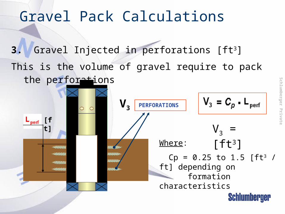
Gravel Pack Calculations
3. Gravel Injected in perforations [ft3]
This is the volume of gravel require to pack the perforations
PERFORATIONSV3
[ft]
Where:
Cp = 0.25 to 1.5 [ft3 / ft] depending on formation characteristics
V3 = [ft3]
Sch
lum
berg
er P
rivate
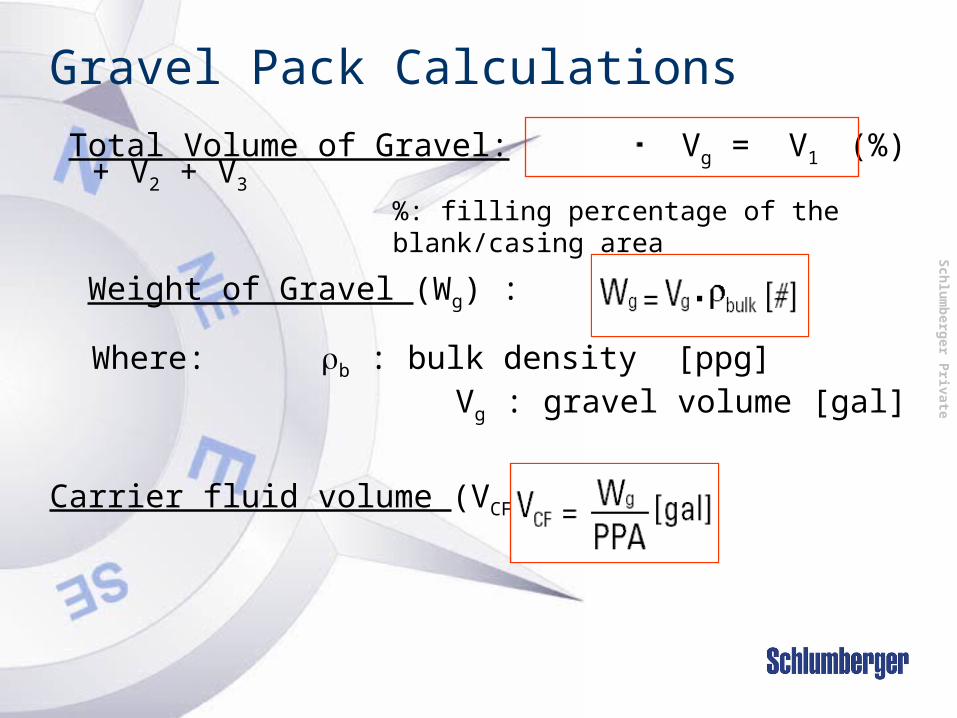
Gravel Pack Calculations
Total Volume of Gravel: Vg = V1 (%) + V2 + V3
Weight of Gravel (Wg) :
Where: b : bulk density [ppg] Vg : gravel volume [gal]
Carrier fluid volume (VCF) :
%: filling percentage of the blank/casing area
Sch
lum
berg
er P
rivate
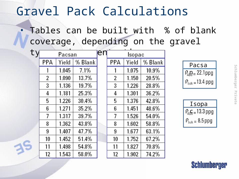
Gravel Pack Calculations
• Tables can be built with % of blank coverage, depending on the gravel type and concentration.
Pacsan
Isopac

Sch
lum
berg
er P
rivate
Gravel Pack Calculations
• We call slurry to any fluid that contains proppant.
• The relation between carrier fluid and slurry is given by:
In this equation the units of VSL will depend on the units of VCLF

Sch
lum
berg
er P
rivate
Gravel Pack Calculations
• Amount of gravel injected in the formation– This will respond to a mass balance
Wform= Wg- (W2+WRO+WSTL) [#]
Where:
Sch
lum
berg
er P
rivate
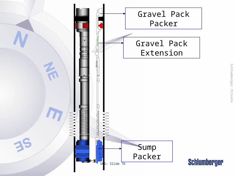
SMS– Slide 76
Gravel Pack Packer
Sump Packer
Gravel Pack Extension

Sch
lum
berg
er P
rivate
SMS– Slide 77
Cased & Perforated Completion Configurations
pjfc
fcpj
p jf c
f cp j
o o
pjfc pj
fc
fcpj fc
pj
Single SingleSelective
Dual

Sch
lum
berg
er P
rivate
SMS– Slide 78
DualSelective
DualSelectiveW/ Spacer
Packer
p jf c p j
f c
f cp j f c
p j
p jf c p j
f c
f cp j f c
p j
Cased & Perforated Completion Configurations

Sch
lum
berg
er P
rivate
SMS– Slide 79
pjfc
fcpj
oo
>1,000 Components
LocatorsSeal SystemsQuantum PackersCirculating HousingsShear SubsBlank PipeIsolation TubingMultizone Seal AssembliesFluid Loss Control EquipmentScreenSump Packers
Fit-for-purposeWell SpecificConfigurations

Sch
lum
berg
er P
rivate
SMS– Slide 80
Questions…