GSO2/FDS/ ISO PAS 22574:2011 ISO PAS 22574:2007
42
ﺍﻟﻌﺭﺒﻴﺔ ﺍﻟﺨﻠﻴﺞ ﻟﺩﻭل ﺍﻟﺘﻌﺎﻭﻥ ﻤﺠﻠﺱ ﻟﺩﻭل ﺍﻟﺘﻘﻴﻴﺱ ﻫﻴﺌﺔGCC STANDARDIZATION ORGANIZATION (GSO) ﻤﺸﺭﻭﻉ: ﻨﻬﺎﺌﻲGSO2/FDS/ ISO PAS 22574:2011 ISO PAS 22574:2007 ﺍﻟﻔﺤﺹ ــ ﺍﻟﻤﻜﺎﺒﺢ ﺒﺒﻁﺎﻨﺎﺕ ﺍﻻﺤﺘﻜﺎﻙ ﻤﻭﺍﺩ ــ ﺍﻟﻁﺭﻕ ﻤﺭﻜﺒﺎﺕ ﺍﻟﻅﺎﻫﺭﻱRoad vehicles — Brake linings frictions materials — Visual إﻋﺪاد ﺍﻟﻤﺭﻜﺒﺎﺕ ﻤﻭﺍﺼﻔﺎﺕ ﻟﻘﻁﺎﻉ ﺍﻟﻔﺭﻋﻴﺔ ﺍﻟﺨﻠﻴﺠﻴﺔ ﺍﻟﻔﻨﻴﺔ ﺍﻟﻠﺠﻨﺔ ﻭﺍﻹﻁﺎﺭﺍﺕ ﻟﺫﻟﻙ ﺒﺸﺄﻨﻬﺎ، ﻭﺍﻟﻤﻼﺤﻅﺎﺕ ﺍﻟﺭﺃﻱ ﻹﺒﺩﺍﺀ ﺘﻭﺯﻴﻌﻬﺎ ﺘﻡ ﺨﻠﻴﺠﻴﺔ ﻗﻴﺎﺴﻴﺔ ﻟﻤﻭﺍﺼﻔﺔ ﻤﺸﺭﻭﻉ ﺍﻟﻭﺜﻴﻘﺔ ﻫﺫﻩ ﻗﻴﺎ ﻜﻤﻭﺍﺼﻔﺔ ﺇﻟﻴﻬﺎ ﺍﻟﺭﺠﻭﻉ ﻴﺠﻭﺯ ﻭﻻ ﻭﺍﻟﺘﺒﺩﻴل، ﻟﻠﺘﻐﻴﻴﺭ ﻋﺭﻀﺔ ﻓﺈﻨﻬﺎ ﻤﻥ ﺍﻋﺘﻤﺎﺩﻫﺎ ﺒﻌﺩ ﺇﻻ ﺨﻠﻴﺠﻴﺔ ﺴﻴﺔ ﺍﻟﺨﻠﻴﺠﻴﺔ ﺍﻟﻬﻴﺌﺔ ﺇﺩﺍﺭﺓ ﻤﺠﻠﺱ.
Transcript of GSO2/FDS/ ISO PAS 22574:2011 ISO PAS 22574:2007

هيئة التقييس لدول مجلس التعاون لدول الخليج العربيةGCC STANDARDIZATION ORGANIZATION (GSO)
نهائي : مشروع
GSO2/FDS/ ISO PAS 22574:2011 ISO PAS 22574:2007
مركبات الطرق ــ مواد الاحتكاك ببطانات المكابح ــ الفحص
الظاهري
Road vehicles — Brake linings frictions materials — Visual
إعداد
والإطاراتاللجنة الفنية الخليجية الفرعية لقطاع مواصفات المركبات
هذه الوثيقة مشروع لمواصفة قياسية خليجية تم توزيعها لإبداء الرأي والملاحظات بشأنها، لذلك
سية خليجية إلا بعد اعتمادها من فإنها عرضة للتغيير والتبديل، ولا يجوز الرجوع إليها كمواصفة قيا
. مجلس إدارة الهيئة الخليجية

٢٠١١ : ٢٢٥٧٤ بي إى إسآيزو/جي إس آو مواصفة قياسية خليجية
GSO STANDARD GSO/ISO PAS 22574:2011
1
تقديم
هيئة التقييس لدول مجلس التعاون لدول الخليج العربية هيئة إقليمية تضم في عضويتها الأجهزة
الوطنية للمواصفات والمقاييس في دول الخليج العربية ، ومن مهام الهيئة إعداد المواصفات القياسية
.بواسطة لجان فنية متخصصة الخليجية
وقد قامت هيئة التقييس لدول مجلس التعاون لدول الخليج العربية ضمن برنامج عمل اللجنة الفنية
بتبني " والإطاراتاللجنة الفنية الخليجية الفرعية لقطاع مواصفات المركبات " ١-٢رقم
مواد ــ الطرق مركبات" ٢٢٥٧٤/٢٠٠٧ بي إى إسالمواصفة القياسية الدولية رقم آيزو
" المنظمة الدولية للتقييس" والتي أصدرتها – “ الظاهري الفحص ــ المكابح ببطانات الاحتكاك
. العربية السعودية بإعداد مشروع هذه المواصفةة وقامت المملكوتمت ترجمتها باللغة العربية ،
وذلك في كمواصفة قياسية خليجية دون إدخال أية تعديلات فنية عليها وقد اعتمدت هذه المواصفة
هـ ، / / ، الذي عقد بتاريخ ( ) اجتماع مجلس إدارة الهيئة رقم
.م/ / الموافق
Foreword
GCC Standardization Organization (GSO) is a regional Organization which consists of the National Standards Bodies of GCC member States. One of GSO main functions is to issue Gulf Standards through specialized technical committees (TCs). GSO through the technical program of committee TC No.2-1: " The Gulf technical Subcommittee for vehicles and tyres standards” has adopted the International Standard No. : ISO PAS 22574:2007 “Road vehicles — Brake linings frictions materials — Visual " issued by International Organization for Standardization which has been translated into Arabic. The Draft Standard has been prepared by Kingdom of Saudi Arabia This standard has been approved as Gulf Standard without any technical modifications by GSO Board of Directors in its meeting No..../.... …….held on / / / H , / / G

Reference numberISO/PAS 22574:2007(E)
© ISO 2007
PUBLICLY AVAILABLE SPECIFICATION
ISO/PAS22574
First edition2007-02-01
Road vehicles — Brake linings frictions materials — Visual inspection
Véhicules routiers — Matériaux de friction des garnitures de freins — Inspection visuelle
ISO/PAS 22574:2007(E)
PDF disclaimer This PDF file may contain embedded typefaces. In accordance with Adobe's licensing policy, this file may be printed or viewed but shall not be edited unless the typefaces which are embedded are licensed to and installed on the computer performing the editing. In downloading this file, parties accept therein the responsibility of not infringing Adobe's licensing policy. The ISO Central Secretariat accepts no liability in this area.
Adobe is a trademark of Adobe Systems Incorporated.
Details of the software products used to create this PDF file can be found in the General Info relative to the file; the PDF-creation parameters were optimized for printing. Every care has been taken to ensure that the file is suitable for use by ISO member bodies. In the unlikely event that a problem relating to it is found, please inform the Central Secretariat at the address given below.
© ISO 2007 All rights reserved. Unless otherwise specified, no part of this publication may be reproduced or utilized in any form or by any means, electronic or mechanical, including photocopying and microfilm, without permission in writing from either ISO at the address below or ISO's member body in the country of the requester.
ISO copyright office Case postale 56 • CH-1211 Geneva 20 Tel. + 41 22 749 01 11 Fax + 41 22 749 09 47 E-mail [email protected] Web www.iso.org
Published in Switzerland
ii © ISO 2007 – All rights reserved

ISO/PAS 22574:2007(E)
© ISO 2007 – All rights reserved iii
Contents Page
Foreword............................................................................................................................................................. v Introduction ....................................................................................................................................................... vi 1 Scope ..................................................................................................................................................... 1 2 Characteristic features for friction materials..................................................................................... 1 2.1 Characteristic features for disc brake pads....................................................................................... 1 2.1.1 Gapping (between material and plate)................................................................................................ 1 2.1.2 Edge chipping ....................................................................................................................................... 2 2.1.3 Splits ...................................................................................................................................................... 2 2.1.4 Minor splits............................................................................................................................................ 3 2.1.5 Plucked and indented spigots............................................................................................................. 3 2.1.6 Poor consolidated spigot holes .......................................................................................................... 4 2.1.7 Excess adhesive on plate .................................................................................................................... 4 2.1.8 Material flash on plate .......................................................................................................................... 5 2.1.9 Abrasive coating ................................................................................................................................... 5 2.1.10 Anti-noise coating runs........................................................................................................................ 6 2.1.11 Skin crazing........................................................................................................................................... 6 2.1.12 Underlayer distribution ........................................................................................................................ 7 2.1.13 Marking .................................................................................................................................................. 7 2.1.14 Unground material surface .................................................................................................................. 8 2.1.15 Paint on friction material surface........................................................................................................ 8 2.1.16 Surface blisters ..................................................................................................................................... 9 2.1.17 Surface indentations ............................................................................................................................ 9 2.1.18 Grinding marks on friction material surface.................................................................................... 10 2.1.19 Higher porosity area ........................................................................................................................... 10 2.1.20 Poorly consolidated friction material ............................................................................................... 11 2.1.21 Surface contamination with foreign matter ..................................................................................... 11 2.1.22 Surface contamination with similar friction material ...................................................................... 12 2.1.23 Friction surface structure .................................................................................................................. 12 2.2 Characteristic features for drum brake linings................................................................................ 13 2.2.1 Chipped edges/corners...................................................................................................................... 13 2.2.2 Edge splits........................................................................................................................................... 14 2.2.3 Drill hole chipping at lining ends ...................................................................................................... 14 2.2.4 Drill hole burrs inside the surface..................................................................................................... 15 2.2.5 Drill hole burrs outside the surface .................................................................................................. 16 2.2.6 Cracks radiating from the rivet hole ................................................................................................. 16 2.2.7 Paint on surface – Lining for riveting and bonding ........................................................................ 17 2.2.8 Surface cracks .................................................................................................................................... 17 2.2.9 Marking ................................................................................................................................................ 18 2.2.10 Moulding skin on inside radius surface – Linings for bonding and riveting................................ 18 2.2.11 Moulding skin on outside radius surface – linings for riveting or bonding ................................. 19 2.2.12 Surface blisters ................................................................................................................................... 19 2.2.13 Surface grind marks ........................................................................................................................... 20 2.2.14 Pitted surface (plucked surface) ....................................................................................................... 20 2.2.15 Surface structure ................................................................................................................................ 21 2.2.16 Poor consolidation ............................................................................................................................. 21 2.2.17 Inside surface indentations ............................................................................................................... 22 2.2.18 Outside surface indentations ............................................................................................................ 22 2.2.19 Concentration of self contained ingredients unless typical of the formulation .......................... 23 2.2.20 High porosity area .............................................................................................................................. 24 2.2.21 Metal wire or plastic reinforcement .................................................................................................. 25 2.2.22 Foreign matter friction surface inclusion......................................................................................... 26

ISO/PAS 22574:2007(E)
iv © ISO 2007 – All rights reserved
2.3 Characteristics features for bonded lined shoes ............................................................................ 26 2.3.1 Lining overhang on shoe platform edge .......................................................................................... 26 2.3.2 Faulty shoes ........................................................................................................................................ 27 2.3.3 Restricted lever movement ................................................................................................................ 27 2.3.4 Stencilled information ........................................................................................................................ 28 2.3.5 Excess adhesive exudation over shoe platform edges .................................................................. 28 2.3.6 Excess adhesive exudation from lining ends .................................................................................. 29 2.3.7 Excess primer...................................................................................................................................... 29 2.3.8 Lining surface condition .................................................................................................................... 30 2.3.9 Gaps between linings and shoe platform......................................................................................... 32

ISO/PAS 22574:2007(E)
© ISO 2007 – All rights reserved v
Foreword
ISO (the International Organization for Standardization) is a worldwide federation of national standards bodies (ISO member bodies). The work of preparing International Standards is normally carried out through ISO technical committees. Each member body interested in a subject for which a technical committee has been established has the right to be represented on that committee. International organizations, governmental and non-governmental, in liaison with ISO, also take part in the work. ISO collaborates closely with the International Electrotechnical Commission (IEC) on all matters of electrotechnical standardization.
International Standards are drafted in accordance with the rules given in the ISO/IEC Directives, Part 2.
The main task of technical committees is to prepare International Standards. Draft International Standards adopted by the technical committees are circulated to the member bodies for voting. Publication as an International Standard requires approval by at least 75 % of the member bodies casting a vote.
In other circumstances, particularly when there is an urgent market requirement for such documents, a technical committee may decide to publish other types of normative document:
⎯ an ISO Publicly Available Specification (ISO/PAS) represents an agreement between technical experts in an ISO working group and is accepted for publication if it is approved by more than 50 % of the members of the parent committee casting a vote;
⎯ an ISO Technical Specification (ISO/TS) represents an agreement between the members of a technical committee and is accepted for publication if it is approved by 2/3 of the members of the committee casting a vote.
An ISO/PAS or ISO/TS is reviewed after three years in order to decide whether it will be confirmed for a further three years, revised to become an International Standard, or withdrawn. If the ISO/PAS or ISO/TS is confirmed, it is reviewed again after a further three years, at which time it must either be transformed into an International Standard or be withdrawn.
Attention is drawn to the possibility that some of the elements of this document may be the subject of patent rights. ISO shall not be held responsible for identifying any or all such patent rights.
ISO/PAS 22574 was prepared by Technical Committee ISO/TC 22, Road vehicles, Subcommittee SC 2, Braking systems and equipment.

ISO/PAS 22574:2007(E)
vi © ISO 2007 – All rights reserved
Introduction
This Publicly Available Specification is based on the “Catalogue of characteristic features for friction materials” of the “FEMFM-Federation of European Manufacturers of Friction Materials” issued the first time in 1980. The FEMFM is a European organization of national associations formed by companies engaged in the development and production of friction materials of various product forms. The description of the characteristic features and their design was reviewed in 1996 when technological processes, especially safety aspects and the demands made by the brake and automobile industry, were given careful consideration.
PUBLICLY AVAILABLE SPECIFICATION ISO/PAS 22574:2007(E)
© ISO 2007 – All rights reserved 1
Road vehicles — Brake linings frictions materials — Visual inspection
1 Scope
Friction linings are composite materials with complex structure. Due to their composition and their production process, visual appearance characteristics can occur which in a precisely defined design are to be regarded as specific to the product. This International Standard defines visual aspect for the identification and assessment of such product characteristics in quality assurance, as well as a basis for commercial and technical agreements. The sequence of the product characteristics represents no order of priority. The brake linings are inspected in the “as supplied” condition, meaning unused. In some characteristic features, there are differences between brake linings with an effective lining pad surface < 120 cm2 and W 120 cm2. The acceptance criteria within the International Standard do not allow any characteristics which could impair the function and performance of brake linings and are applied unless there are other agreements between the customer and the supplier.
2 Characteristic features for friction materials
2.1 Characteristic features for disc brake pads
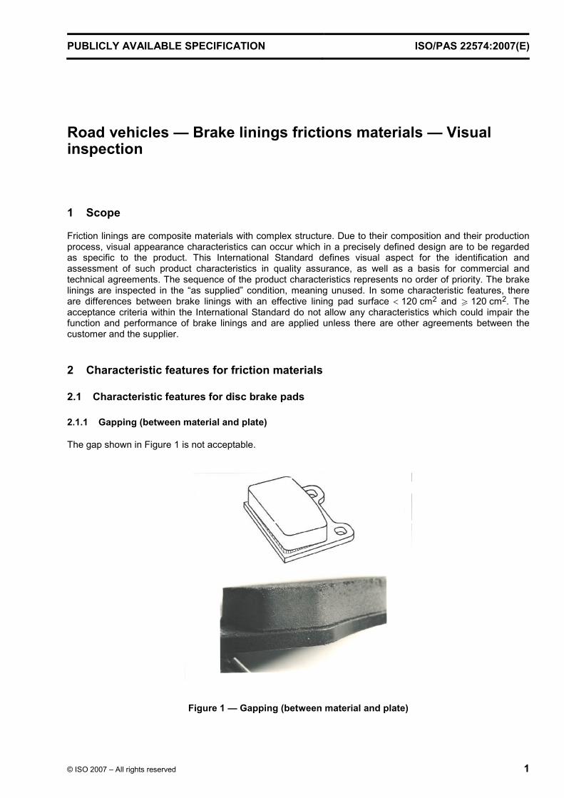
2.1.1 Gapping (between material and plate)
The gap shown in Figure 1 is not acceptable.
Figure 1 — Gapping (between material and plate)

ISO/PAS 22574:2007(E)
2 © ISO 2007 – All rights reserved
2.1.2 Edge chipping
In the case of a disc brake pad with a surface less than 120 cm2 a maximum of 1 % of the edge may chip.
In the case of a disc brake pad with a surface equal or more than 120 cm2 a maximum of 0,5 % of the edge may chip.
Figure 2 — Edge chipping
2.1.3 Splits
Splits having a length of more than 30 mm or more than 10 mm on corners or deeper than 1,5 mm shall not be accepted (see Figure 3).
Figure 3 — Splits
ISO/PAS 22574:2007(E)
© ISO 2007 – All rights reserved ROOF/ÉPREUVE 3
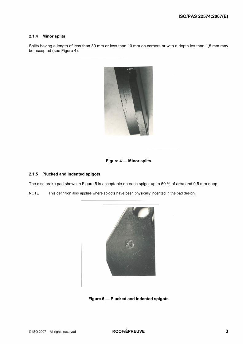
2.1.4 Minor splits
Splits having a length of less than 30 mm or less than 10 mm on corners or with a depth les than 1,5 mm may be accepted (see Figure 4).
Figure 4 — Minor splits
2.1.5 Plucked and indented spigots
The disc brake pad shown in Figure 5 is acceptable on each spigot up to 50 % of area and 0,5 mm deep.
NOTE This definition also applies where spigots have been physically indented in the pad design.
Figure 5 — Plucked and indented spigots

ISO/PAS 22574:2007(E)
4 © ISO 2007 – All rights reserved
2.1.6 Poor consolidated spigot holes
The disc brake pad shown in Figure 6 is acceptable if only one spigot is affected with up to 20 % of the volume being low density. This definition also applies where spigots have been physically indented in the pad design.
Figure 6 — Poor consolidated spigot holes
2.1.7 Excess adhesive on plate
Excess adhesive on plate is acceptable provided the fitment of the part is not affected. (See Figure 5.)
Figure 7 — Excess adhesive on the plate

ISO/PAS 22574:2007(E)
© ISO 2007 – All rights reserved ROOF/ÉPREUVE 5
2.1.8 Material flash on plate
A material flash on plate is acceptable up to 1mm thick outside functional zones. Flash shall be secured to back plate. (See Figure 8.)
Figure 8 — Material flash on plate
2.1.9 Abrasive coating
The disc brake pad is acceptable if at least 90 % of the surface is coated. (See Figure 9.)
Figure 9 — Abrasive coating
ISO/PAS 22574:2007(E)
6 © ISO 2007 – All rights reserved
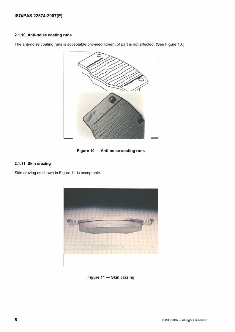
2.1.10 Anti-noise coating runs
The anti-noise coating runs is acceptable provided fitment of part is not affected. (See Figure 10.)
Figure 10 — Anti-noise coating runs
2.1.11 Skin crazing
Skin crazing as shown in Figure 11 is acceptable.
Figure 11 — Skin crazing

ISO/PAS 22574:2007(E)
© ISO 2007 – All rights reserved ROOF/ÉPREUVE 7
2.1.12 Underlayer distribution
Presence of underlayer is acceptable on pad surface up to 2 % of area, if the distribution is according to the specification. (See Figure 12.)
Figure 12 — Under-layer distribution
2.1.13 Marking
The marking shall be clear and legible.
Figure 13 — Marking
ISO/PAS 22574:2007(E)
8 © ISO 2007 – All rights reserved
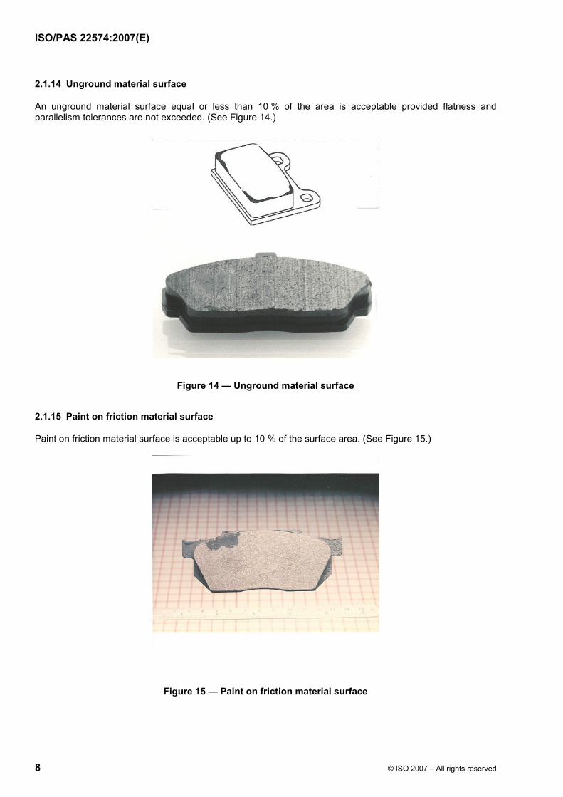
2.1.14 Unground material surface
An unground material surface equal or less than 10 % of the area is acceptable provided flatness and parallelism tolerances are not exceeded. (See Figure 14.)
Figure 14 — Unground material surface
2.1.15 Paint on friction material surface
Paint on friction material surface is acceptable up to 10 % of the surface area. (See Figure 15.)
Figure 15 — Paint on friction material surface

ISO/PAS 22574:2007(E)
© ISO 2007 – All rights reserved ROOF/ÉPREUVE 9
2.1.16 Surface blisters
Surface blisters are acceptable if no surface lift is detectable. (See Figure 16.)
Figure 16 — Surface blisters
2.1.17 Surface indentations
Surface indentations are acceptable up to 2 % of the surface in total, but a single indentation shall not exceed 1 % of the material surface; (See Figure 17.)
Figure 17 — Surface indentations
ISO/PAS 22574:2007(E)
10 © ISO 2007 – All rights reserved
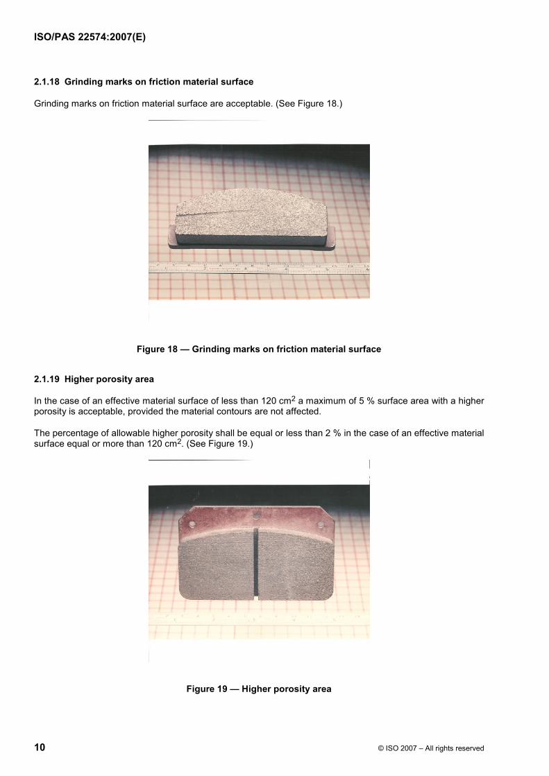
2.1.18 Grinding marks on friction material surface
Grinding marks on friction material surface are acceptable. (See Figure 18.)
Figure 18 — Grinding marks on friction material surface
2.1.19 Higher porosity area
In the case of an effective material surface of less than 120 cm2 a maximum of 5 % surface area with a higher porosity is acceptable, provided the material contours are not affected.
The percentage of allowable higher porosity shall be equal or less than 2 % in the case of an effective material surface equal or more than 120 cm2. (See Figure 19.)
Figure 19 — Higher porosity area
ISO/PAS 22574:2007(E)
© ISO 2007 – All rights reserved ROOF/ÉPREUVE 11
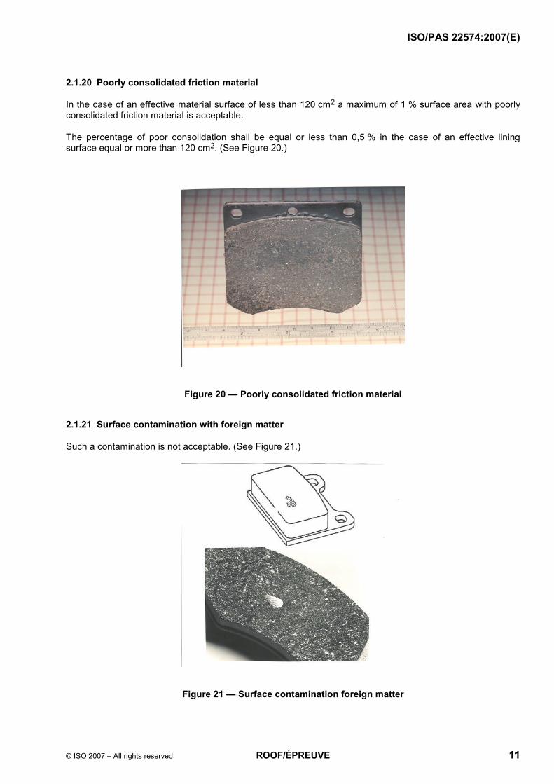
2.1.20 Poorly consolidated friction material
In the case of an effective material surface of less than 120 cm2 a maximum of 1 % surface area with poorly consolidated friction material is acceptable.
The percentage of poor consolidation shall be equal or less than 0,5 % in the case of an effective lining surface equal or more than 120 cm2. (See Figure 20.)
Figure 20 — Poorly consolidated friction material
2.1.21 Surface contamination with foreign matter
Such a contamination is not acceptable. (See Figure 21.)
Figure 21 — Surface contamination foreign matter

ISO/PAS 22574:2007(E)
12 © ISO 2007 – All rights reserved
2.1.22 Surface contamination with similar friction material
Spots on friction material with a surface equal or less than 1 % of the total surface are acceptable.
Spots on friction material with a surface equal or less than 2 % of the total surface are acceptable, only if the friction properties are not affected.
2.1.23 Friction surface structure
In the case of an effective material surface of less than 120 cm2 the concentration of self contained ingredients is acceptable up to 5 % of the surface area but not continuous.
In the case of an effective material surface equal or more than 120 cm2 the concentration of self contained ingredients is acceptable up to 3 % of the surface area but not continuous. (See Figure 22.)
Non homogenous appearance is accepted for special qualities including surface plucking. (See Figure 23.)
Figure 22 — Friction surface structure
Figure 23

ISO/PAS 22574:2007(E)
© ISO 2007 – All rights reserved ROOF/ÉPREUVE 13
2.2 Characteristic features for drum brake linings
2.2.1 Chipped edges/corners
In the case of a lining surface of less than 120 cm2 chipped edges/corners are acceptable up to 10 mm2 and half the lining thickness. No more than 2 are allowed per lining. (See Figure 24.)
In the case of a lining surface equal or more than 120 mm2 chipped edges/ corners are acceptable up to 20 mm2 and half the lining thickness. No more than 2 are allowed per lining. (See Figure 25.)
Figure 24 — Chipped edges/corners on linings < 120 mm2
Figure 25 — Chipped edges/ corners W 120 mm2

ISO/PAS 22574:2007(E)
14 © ISO 2007 – All rights reserved
2.2.2 Edge splits
Edge splits are not acceptable. (See Figure 26.)
Figure 26 — Edge splits
2.2.3 Drill hole chipping at lining ends
The lining shown in Figure 27 is not acceptable.
The lining shown in Figure 28 is acceptable if one hole only is concerned.
Figure 27 — Drill hole chipping at lining ends

ISO/PAS 22574:2007(E)
© ISO 2007 – All rights reserved ROOF/ÉPREUVE 15
Figure 28 — Drill hole chipping at lining ends
2.2.4 Drill hole burrs inside the surface
Drill hole burrs on the inside the surface are not acceptable. (See Figure 29.)
Figure 29 — Drill hole burrs inside the surface
ISO/PAS 22574:2007(E)
16 © ISO 2007 – All rights reserved
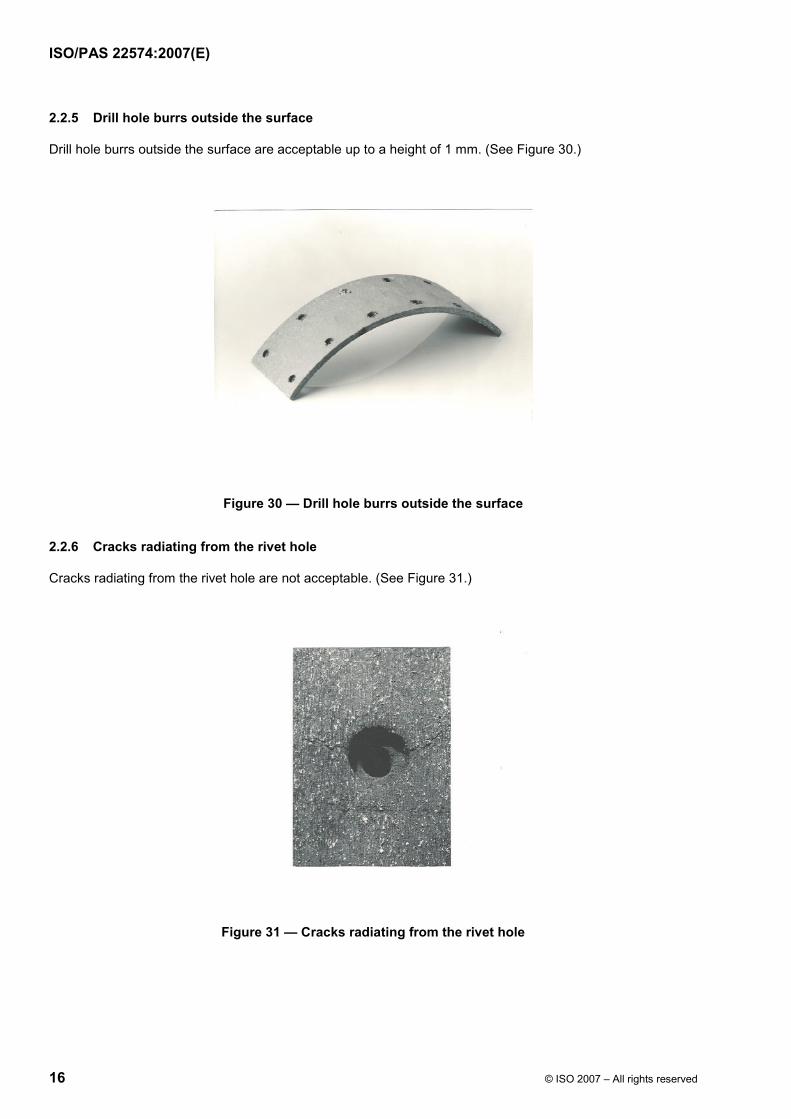
2.2.5 Drill hole burrs outside the surface
Drill hole burrs outside the surface are acceptable up to a height of 1 mm. (See Figure 30.)
Figure 30 — Drill hole burrs outside the surface
2.2.6 Cracks radiating from the rivet hole
Cracks radiating from the rivet hole are not acceptable. (See Figure 31.)
Figure 31 — Cracks radiating from the rivet hole
ISO/PAS 22574:2007(E)
© ISO 2007 – All rights reserved ROOF/ÉPREUVE 17
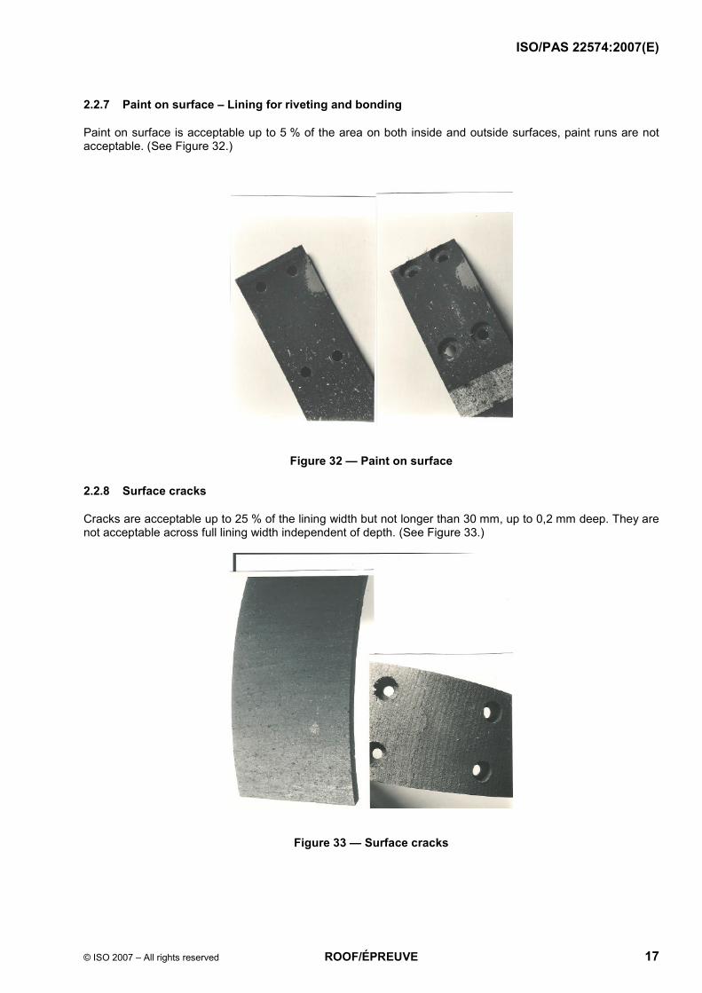
2.2.7 Paint on surface – Lining for riveting and bonding
Paint on surface is acceptable up to 5 % of the area on both inside and outside surfaces, paint runs are not acceptable. (See Figure 32.)
Figure 32 — Paint on surface
2.2.8 Surface cracks
Cracks are acceptable up to 25 % of the lining width but not longer than 30 mm, up to 0,2 mm deep. They are not acceptable across full lining width independent of depth. (See Figure 33.)
Figure 33 — Surface cracks

ISO/PAS 22574:2007(E)
18 © ISO 2007 – All rights reserved
2.2.9 Marking
Marking shall be legible. (See Figure 34.)
Figure 34 — Marking
2.2.10 Moulding skin on inside radius surface – Linings for bonding and riveting
Where inside ground finish is specified for linings for bonding, up to 3 % of surface are acceptable provided the unground area is not at the lining ends and dimensional specifications are maintained.
Where inside ground finish is specified for linings for riveting, up to 10 % of surface are acceptable provided the unground area is not at the lining ends and dimensional specifications are maintained. (See Figure 35.)
Figure 35 — Moulding skin on inside radius surface

ISO/PAS 22574:2007(E)
© ISO 2007 – All rights reserved ROOF/ÉPREUVE 19
2.2.11 Moulding skin on outside radius surface – linings for riveting or bonding
Moulded skin is acceptable up to 3 % of surface area provided dimensional specifications are maintained. (See Figure 36.)
Figure 36 — Moulding skin on outside radius surface
2.2.12 Surface blisters
Surface blisters are not acceptable (See Figure 37.)
Figure 37 — Surface blisters

ISO/PAS 22574:2007(E)
20 © ISO 2007 – All rights reserved
2.2.13 Surface grind marks
Surface grind marks are acceptable as long as dimensional specifications are maintained. (See Figure 38.)
Figure 38 — Surface grind marks
2.2.14 Pitted surface (plucked surface)
Pitted surface which is typical of certain materials is acceptable (See Figure 39.)
Figure 39 — Pitted surface

ISO/PAS 22574:2007(E)
© ISO 2007 – All rights reserved ROOF/ÉPREUVE 21
2.2.15 Surface structure
In case of surface contamination by self contained ingredients (poor distribution) i.e. unopened fibres the lining is acceptable if the contamination equals or is less than 2 % of the friction side area and if the contamination equals or is less than 4 % of the non friction side area. (See Figure 40.)
Figure 40 — Surface structure
2.2.16 Poor consolidation
The poor consolidation as shown in Figure 41 is not acceptable.
Figure 41 — Poor consolidation
ISO/PAS 22574:2007(E)
22 © ISO 2007 – All rights reserved
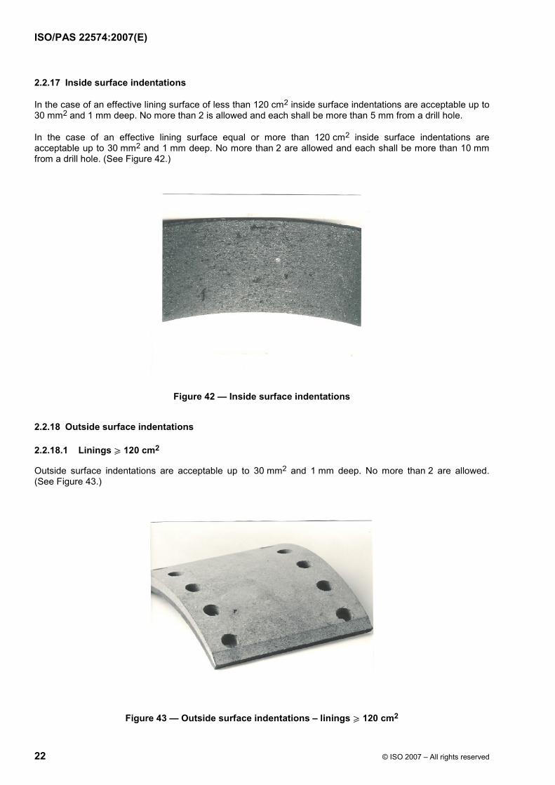
2.2.17 Inside surface indentations
In the case of an effective lining surface of less than 120 cm2 inside surface indentations are acceptable up to 30 mm2 and 1 mm deep. No more than 2 is allowed and each shall be more than 5 mm from a drill hole.
In the case of an effective lining surface equal or more than 120 cm2 inside surface indentations are acceptable up to 30 mm2 and 1 mm deep. No more than 2 are allowed and each shall be more than 10 mm from a drill hole. (See Figure 42.)
Figure 42 — Inside surface indentations
2.2.18 Outside surface indentations
2.2.18.1 Linings W 120 cm2
Outside surface indentations are acceptable up to 30 mm2 and 1 mm deep. No more than 2 are allowed. (See Figure 43.)
Figure 43 — Outside surface indentations – linings W 120 cm2

ISO/PAS 22574:2007(E)
© ISO 2007 – All rights reserved ROOF/ÉPREUVE 23
2.2.18.2 Linings < 120 cm2
Outside surface indentations are acceptable up to 20 mm2 and 1 mm deep. No more than 2 are allowed. (See Figure 44.)
Figure 44 — Outside surface indentations - lining < 120 cm2
2.2.19 Concentration of self contained ingredients unless typical of the formulation
In the outside radius a maximum of 1 % of the surface is acceptable, but each concentration area to be a maximum area of 25 mm2. (See Figure 45.)
Figure 45 — Concentration of self contained ingredients (Outside radius)

ISO/PAS 22574:2007(E)
24 © ISO 2007 – All rights reserved
In the inside radius a maximum of 2 % of the surface is acceptable, each to be a maximum area of 50 mm2. (See Figure 46.)
Figure 46 — Concentration of self contained ingredients (Inside radius)
2.2.20 High porosity area
A high porosity area is acceptable provided the overall density of linings is specified and the profile is not affected. (See Figure 47.)
Figure 47 — High porosity area
ISO/PAS 22574:2007(E)
© ISO 2007 – All rights reserved ROOF/ÉPREUVE 25
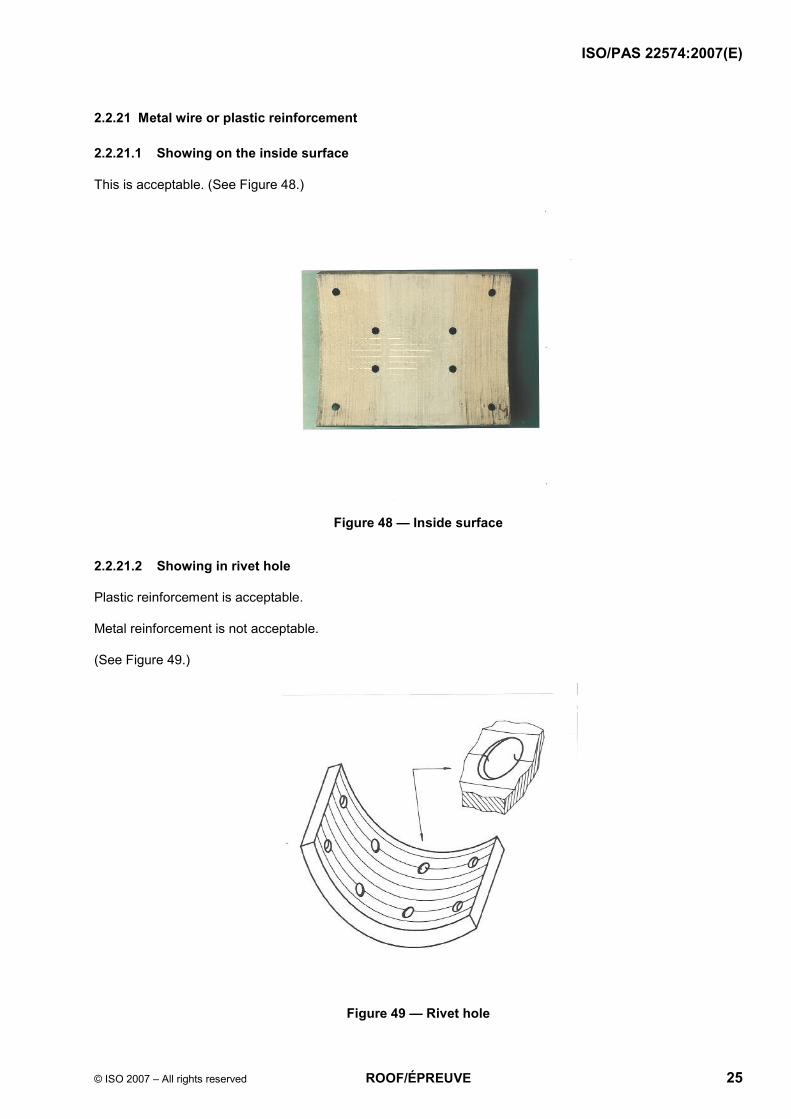
2.2.21 Metal wire or plastic reinforcement
2.2.21.1 Showing on the inside surface
This is acceptable. (See Figure 48.)
Figure 48 — Inside surface
2.2.21.2 Showing in rivet hole
Plastic reinforcement is acceptable.
Metal reinforcement is not acceptable.
(See Figure 49.)
Figure 49 — Rivet hole

ISO/PAS 22574:2007(E)
26 © ISO 2007 – All rights reserved
2.2.22 Foreign matter friction surface inclusion
Foreign matter friction surface inclusion is not acceptable, but for inclusions of similar friction material it may be accepted as follows (see Figure 50):
⎯ in the case of a lining surface of less than 120 cm2 an inclusion of a surface of a maximum of 25 mm2 is acceptable;
⎯ in the case of a lining surface of 120 cm2 or more an inclusion of a surface of a maximum of 50 mm2 is acceptable.
Figure 50 — Inclusions
2.3 Characteristics features for bonded lined shoes
2.3.1 Lining overhang on shoe platform edge
A lining overhang on shoe platform edge is acceptable up to a maximum of 1 mm over whole lining length on one edge only (unless otherwise stated in the specification). (See Figure 51.)
Figure 51 — Lining overhang on shoe platform edge

ISO/PAS 22574:2007(E)
© ISO 2007 – All rights reserved ROOF/ÉPREUVE 27
2.3.2 Faulty shoes
Faulty shoes damaged in bonding process are not acceptable unless of a minor nature not affecting fitment. (See Figure 52.)
Figure 52 — Faulty shoes
2.3.3 Restricted lever movement
A restricted lever movement is not acceptable. It shall not be restricted by excess primer or incorrect riveting. (See Figure 53.)
Figure 53 — Restricted lever movement
ISO/PAS 22574:2007(E)
28 © ISO 2007 – All rights reserved
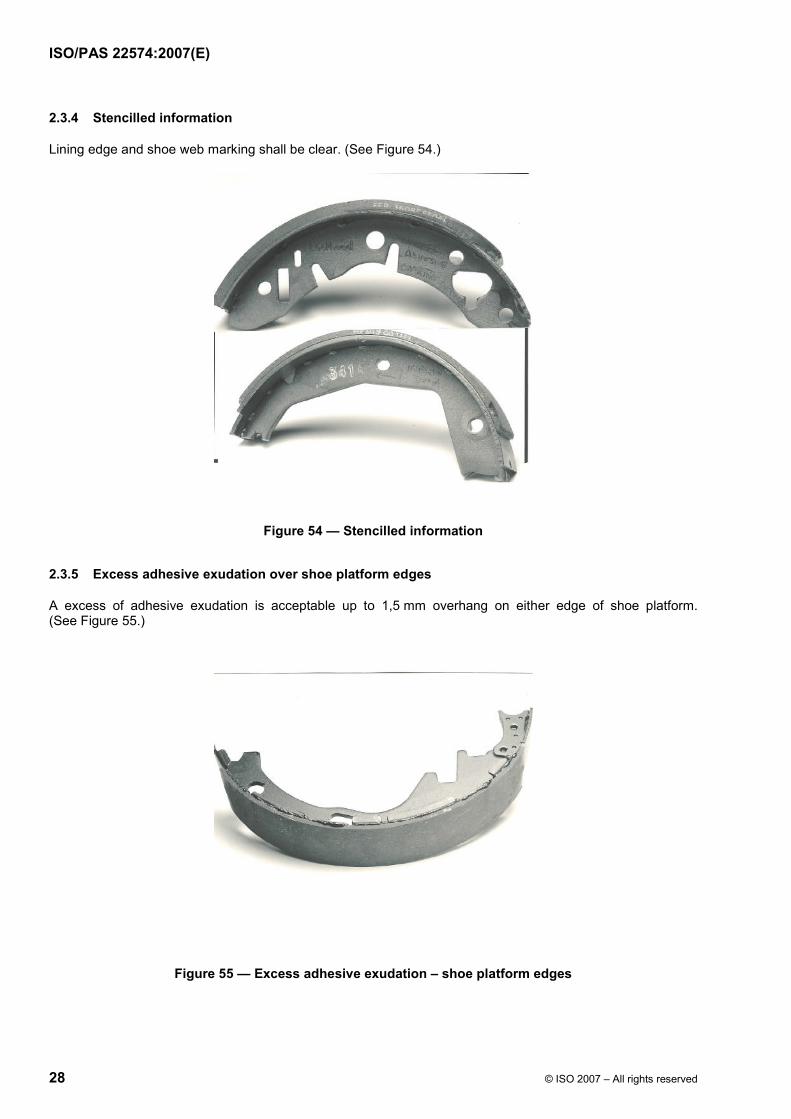
2.3.4 Stencilled information
Lining edge and shoe web marking shall be clear. (See Figure 54.)
Figure 54 — Stencilled information
2.3.5 Excess adhesive exudation over shoe platform edges
A excess of adhesive exudation is acceptable up to 1,5 mm overhang on either edge of shoe platform. (See Figure 55.)
Figure 55 — Excess adhesive exudation – shoe platform edges

ISO/PAS 22574:2007(E)
© ISO 2007 – All rights reserved ROOF/ÉPREUVE 29
2.3.6 Excess adhesive exudation from lining ends
An excess adhesive exudation from lining ends is acceptable. (See Figure 56.)
Figure 56 — Excess adhesive exudation – lining ends
2.3.7 Excess primer
The excess primer, e.g. in web location holes and abutment areas is acceptable provided the fitment and the performances are not affected. (See Figure 57.)
Figure 57 — Excess primer

ISO/PAS 22574:2007(E)
30 © ISO 2007 – All rights reserved
2.3.8 Lining surface condition
2.3.8.1 Rigid material ground on the shoe — Unground areas
An unground area is acceptable if it is 10 % or less of the lining surface area with a depth of 0,2 mm or less. (See Figure 58.)
Figure 58 — Lining surface condition
2.3.8.2 Rigid material ground on the shoe – Grinding marks
Grinding marks are acceptable if they are 20 % or less of the lining surface area with a depth of 0,2 mm or less. (See Figure 59.)
Figure 59 — Lining surface condition

ISO/PAS 22574:2007(E)
© ISO 2007 – All rights reserved ROOF/ÉPREUVE 31
2.3.8.3 Flexible material
Bonding band impression causing lip of material on lining edge is not acceptable. (See Figure 60.)
Bonding band impression causing reduction in material thickness is acceptable at lining ends over 5 % surface area, provided conditions of lining overhang are met. (See Figure 61.)
Figure 60 — Flexible material (1)
Figure 61 — Flexible material (2)

ISO/PAS 22574:2007(E)
32 © ISO 2007 – All rights reserved
2.3.9 Gaps between linings and shoe platform
2.3.9.1 Lining edges
A gap is acceptable if it is equal or less than 0,15 mm wide, equal or less than 5,0 mm deep and up to a maximum of 25 % of one side length. (See Figure 62.)
Figure 62 — Gap in lining edges
2.3.9.2 Lining ends (end lifts)
A gap between lining and shoe platform lining ends (end lift) is not acceptable. (See Figure 63.)
Figure 63 — Gap in lining ends


ISO/PAS 22574:2007(E)
ICS 43.040.40 Price based on 32 pages
© ISO 2007 – All rights reserved