SELECTINg CHECK VALVES SeLeccIón de váLvuLAS de … · Junta de cuerpo True union True union...
90
188 SELECTINg CHECK VALVES SELECCIóN DE VáLVULAS DE RETENCIóN SPRING SERIES SERIE MUELLE BALL SERIES SERIE BOLA SWINg CHECK CLAPETA D16 - D63 (⅜” - 2”) D75 - D110 (2½” - 4”) D20 - D63 (½” - 2”) D75 - D110 (2½” - 4”) D75 - D315 (2½” - 12”) Sizes Medidas PN 16 240 psi PN 10 150 psi PN 16 240 psi PN 10 150 psi PN 6 90 psi PN PVC-U PVC-C PVC-U PVC-C PVC-U Body material Material cuerpo EPDM FPM EPDM FPM EPDM FPM Body O-rings Junta de cuerpo True union True union Flanges Connection type Tipo conexión FOOT VALVES VáLVULAS DE PIE CHECK VALVES SELECTION CRITERIA
Transcript of SELECTINg CHECK VALVES SeLeccIón de váLvuLAS de … · Junta de cuerpo True union True union...

188
SELECTINg CHECK VALVESSeLeccIón de váLvuLAS de ReTencIón
SPRING SERIESSeRIe MueLLe
BALL SERIESSeRIe boLA
SWINg CHECKcLAPeTA
D16 - D63(⅜” - 2”)
D75 - D110(2½” - 4”)
D20 - D63(½” - 2”)
D75 - D110(2½” - 4”)
D75 - D315(2½” - 12”)
SizesMedidas
PN 16240 psi
PN 10150 psi
PN 16240 psi
PN 10150 psi
PN 690 psi
PN
PVC-UPVC-C
PVC-UPVC-C
PVC-U
Body materialMaterial cuerpo
EPDMFPM
EPDMFPM
EPDMFPM
Body O-ringsJunta de cuerpo
True union
True union
Flanges
Connection typeTipo conexión
FOOT VALVESváLvuLAS de PIe
CHECK VALVES SELECTION CRITERIA

189
Shuts off flow by means of a cone pushed by a spring which helps it to obtain an entirely watertight closure.The difference in pressure between two points of the installation is able to overcome the resistance of the spring, thus making the fluid flow in the desired direction and preventing the flow passage in the other.Transported material• Clean liquids, not viscous and without containing particles.Installation• Horizontal or vertical.Materials• Metallic spring (stainless steel).Piping• Moderated flows.Others• Very reliable closing.
Closing by means of a sphere which closes against a joint.The ball closing is by gravity, which means that the most usual assembly position is vertical, with an inverse pressure at fluid presence.Transported material• Any type of liquid.Installation• Vertical, horizontal (see minimum pressure).Materials• Made completely in plastic.Piping• Ideally suited for large flows.Others• Minimum pressure loss.
The flap or disk has only one opening direction.Installation takes up minimum space in the system.Transported material• Any type of liquid, it does not obstruct the passage of the fluid.Installation• Vertical, horizontal (see minimum pressure). Takes up minimum space in the system.Materials• All parts which are in contact with fluid are plastic.Piping• High flows.Others• Used for low pressures and big piping sizes.
Cierre por medio de un cono empujado por un muelle que la ayuda a realizar un cierre completamente estanco.La diferencia de presión entre dos puntos de la instalación es capaz de vencer la resistencia del muelle, discurriendo así el fluido en el sentido previsto e impidiéndose el paso en sentido contrario.Material conducido• Líquidos limpios, no viscosos y sin partículas en suspensión.Instalación• Horizontal o vertical.Materiales• Muelle metálico (acero inoxidable).Conducciones• Caudales moderados.Otros• Cierre muy fiable.
Cierre por medio de una esfera que cierra contra una junta.El cierre de la bola siempre es por gravedad, lo cual significa que la posición de montaje más usual es en circuitos verticales y con una presión inversa con presencia de fluido.Material conducido• Cualquier tipo de líquido.Instalación• Vertical, horizontal (consultar presión mínima).Materiales• Fabricada completamente en plástico.Conducciones• Ideal para altos caudales.Otros• Mínima pérdida de carga.
La clapeta o disco sólo tiene un sentido de apertura.Instalación sin ocupar casi espacio del sistema.Material conducido• Cualquier tipo de líquido, no ofrece obstáculos al paso del fluido.Instalación• Vertical, horizontal (consultar presión mínima), usa poco espacio de instalación.Materiales• Partes en contacto con el fluido, de plástico.Conducciones• Caudales elevados.Otros• Usada para bajas presiones y diámetros muy grandes.
Las válvulas de pie son un tipo particular de válvula de retención que se instala en la base de la tubería de aspiración de una bomba, para evitar que se produzca el vaciado de la conducción de impulsión.La válvula se debe instalar entre la bomba y el tanque, permitiendo que el fluido acceda a la bomba e impidiendo que regrese al tanque. La entrada de la válvula suele estar protegida con un filtro para impedir la entrada de elementos extraños que puedan existir en el depósito o pozo de aspiración.
Foot valves are a particular type of check valves which are installed on the base of an aspiration pipe of a pump to prevent the impulsion pipe from emptying.The valve must be installed between the pump and the tank in order to let the fluid access the pump and stopping it when returning to the tank. The entry of the valve is protected by a screen filter to prevent the entry of unwanted elements which could exist in the tank or deposit.
Foot valve operation Funcionamiento válvula de pie
Concept&
typical application
Conceptoy
aplicaciones típicas
CHECK VALVES SELECTION CRTERIA

190
Pvc-U check valveS - SPring SerieS válvulaS anTi-reTorno Pvc-u - Serie Muelle
Sizes Solvent cement D16 - D110 (DN10 - DN100)Threaded ⅜” - 4”
Standards Solvent socket - Metric, British standard, ASTM, JISThreaded - BSP, NPT
EN ISO 1452, EN ISO 15493, BS 4346-1, ASTM D 2467, JIS K 6743ISO 228-1, ASTM D 2464
Working pressure @ 20ºC (73ºF)
D16-D63 (⅜” - 2”): PN 16 (240 psi)D75 - D110 (2”1/2 - 4”): PN 10 (150 psi)
Minimum working pressure
Materials O-rings: EPDM / FPM
Characteristics • May be used either vertically and horizontally.• 100% factory tested.• Easy installation and maintenance.• Available in PVC-U and Corzan® PVC-C.• Resistance to many inorganic chemicals.• Excellent flow characteristics.
• Se pueden usar indistintamente verticalmente o horizontalmente.• Probadas al 100% en fábrica.• Fácil instalación y mantenimiento.• Disponibles en PVC-U y Corzan® PVC-C.• Resistencia a múltiples substancias químicas inorgánicas.• Excelentes características de conducción.
Certifications / regulations Check valve design regulation - ISO 16137:2006
PVC-U CHECK VALVES SPRINg SERIES

191
FIG. Parts Despiece Material
1 Body Cuerpo PVC-U
2 Cone Cono de cierre PVC-U
3 Spring Muelle Stainless Steel AISI 302 / PTFE coated *
4 Union nut Tuerca PVC-U
5 End connector Manguito enlace PVC-U
6 Cone o-ring Junta cono EPDM / FPM
7 End connector o-ring Junta manguito EPDM / FPM
8 Seal-carrier Portajuntas PVC-U
1
2
4
8
57
3
6
4
5
PVC-U CHECK VALVES SPRINg SERIES
20 years / water flow20 années / fluide de l�eau20 años / fluido de agua20 anos / caudal de água
18
16
14
12
10
8
6
4
2
0
0 10 20 30 40 50 60
Temperature / Température / Temperatura / Temperatura
Pres
sure
/Pre
ssio
n/ P
resió
n/ P
ress
ão
°C32 50 68 86 104 122 140 °F
barpsi270
240
210
180
150
120
90
60
30
0
DN
15
-3/8
”-½
”
DN
20
-¾
”DN
25
-1”
DN
32
-1¼
”
DN
40
-1½
”DN
50
-2”
DN
65
-2½
”
0,1
10 (l/min)
bar
Kv (l/min , p = 1 bar)
0,01
0,001
1
100 1.000 10.000
DN
80
-3”
DN
100
-4”
2,64 (GPM)26,42 264 2.642
1,50
0,15
0,01
15,0
psi
Flow / Débit / Caudal / Caudal
Pres
sure
loss
/Per
tede
char
ge/
Pérd
ida
deca
rga
/Per
dasd
eca
rga
PN 10
PN 16
PreSSUre / teMPeratUre graPhdiaGraMa PreSión / TeMPeraTura
Pres
sure
/ Pr
esió
n
Temperature / Temperatura
vida útil: 25 añosPresión hidrostática máxima que un com-ponente es capaz de soportar en servicio continuo (sin sobrepresión)
Life: 25 yearsHydrostatic maximum pressure a comp-nent may outstand in continous service (without overpressure)

192
Pres
sure
loss
/ Per
tede
char
ge/
Pérd
ida
deca
rga
/ Per
das d
eca
rga
Flow / Débit / Caudal / Caudal
100 1.000 10.000
1
mca
(l/min)
10
26,4 264 2.642 (GPM)
1,5
psi
15
10
Temperature / Température / Temperatura / Temperatura
20 years / water flow20 années / fluide de l�eau20 años / fluido de agua20 anos / caudal de água
Pres
sure
/Pre
ssio
n/ P
resió
n/ P
ress
ão
18
16
14
12
10
8
6
4
2
0
0 10 20 30 40 50 60 70 80 90 °C32 50 68 86 104 122 140 158 176 194 °F
barpsi
PVC -U
PVC-C
270
240
210
180
150
120
90
60
30
0
PN 16 (240 psi)
PN 10 (150 psi)
D20
-½
”D25
-¾
”D32
-1”
D40
-1¼
”D50
-1½
”
D63
-2”
D75
-2½
”
D90
-3”
D110
-4”
D16
-3/8
”
0
D 20-½” 25-¾” 32-1” 40-1¼” 50-1½” 63-2” 75-2½” 90 - 3” 110- 4”
DN 15 20 25 32 40 50 65 80 100
Kv100 68 133 208 383 667 850 1533 1160 1200
Cv 5 9 15 27 47 60 107 81,2 84
PVC-U CHECK VALVES SPRINg SERIES
OpenAbierto
ClosedCerrado
D P (bar) Minimum opening
P (bar) Maximum opening
P (psi) Minimum opening
P (psi) Maximum opening
20 0,11 0,19 1,57 2,71
25 0,035 0,067 0,5 0,95
32 0,042 0,077 0,6 1,1
40 0,038 0,069 0,54 0,98
50 0,063 0,088 0,9 1,25
63 0,038 0,060 0,54 0,85
75 0,031 0,060 0,44 0,85
90 0,025 0,060 0,35 0,85
OPening PreSSUrePreSión de aPerTura
Minimum pressure: opening startMaximum pressure: fully open valve
Presión mínima: inicio aperturaPresión máxima: válvula completamente abierta
PreSSUre lOSS DiagraMdiaGraMa de PÉrdidaS de carGa
relative FlOWFluJo relaTivo
Cv = Kv100 / 14,28Kv100 (l/min, ∆p = 1 bar)Cv (GPM, ∆p = 1 psi)
Pres
sure
loss
/ Pé
rdid
a de
carg
a
Flow / caudal
bar
1
0,1
Relative flow in fully open valve (maximum opening)Flujo relativo en válvula completamente abierta (apertura máxima)

193
inStrUcciOneS De MOntaje
Uniones encoladas o roscadasAfloje las tuercas (4) de la válvula y sepárelas de los manguitos (5). Introduzca las tuercas en los tubos y a continuación fije los manguitos en los extremos del tubo. Las uniones encoladas se realizarán con un adhesivo para tubos de PVC-U o PVC-C rígido y no se aplicará presión hasta transcurridas al menos 1 hora por bar. En las uniones roscadas se colocará cinta de PTFE en las roscas macho. A continuación ya podrá colocarse la válvula entre los manguitos y apretar a mano las tuercas sobre la válvula.
aSSeMBly inStrUctiOnS
Solvent socket or threaded unionsLoosen the valve union nuts (4) and separate these and the end connectors (5) from the valve body. Pass the pipe through the nuts and then place the bushes over the end of the pipe. The socket unions should be guied onto the pipe using a PVC-U or PVC-C adhesive and pressure should not be applied to the system until a drying period of at least 1 hour per bar of working pressure has elapsed. In the case of threaded unions, PTFE tape should be applied to the male threads. The pipes can now be attached to the valve by hand tightening down the nuts.
1
2
3
4
5
PVC-U CHECK VALVES SPRINg SERIES
Cv = Kv100 / 14,28Kv100 (l/min, ∆p = 1 bar)Cv (GPM, ∆p = 1 psi)

194
D DN PN REF. CODE16 10 16 05 67 016 09010
20 15 16 05 67 020 09011
25 20 16 05 67 025 09012
32 25 16 05 67 032 09013
40 32 16 05 67 040 09014
50 40 16 05 67 050 09015
63 50 16 05 67 063 09016
75 65 10 05 67 075 09017
90 80 10 05 67 090 09018
110 80 10 05 67 110 09019
110 100 10 05 67 111 37076
L H E14 84 52
16 84 52
19 108 62
22 119 70
26 142 84
31 162 94
38 192 117
44 232 148
51 269 179
61 279 179
61 279 179
G DN PN REF. CODE⅜” 10 16 05 67 616 09020
½” 15 16 05 67 620 09021
¾” 20 16 05 67 625 09022
1” 25 16 05 67 632 09023
1¼” 32 16 05 67 640 09024
1½” 40 16 05 67 650 09025
2” 50 16 05 67 663 09026
2½” 65 10 05 67 675 09027
3” 80 10 05 67 690 09028
4” 80 10 05 67 710 09029
4” 100 10 05 67 711 37077
L H E14 84 52
16 84 52
19 108 62
22 119 70
26 142 84
31 162 94
38 192 117
44 232 148
51 269 179
61 279 179
61 279 179
D DN PN REF. CODE16 10 16 05 67 016 VI 18751
20 15 16 05 67 020 VI 18752
25 20 16 05 67 025 VI 18753
32 25 16 05 67 032 VI 18754
40 32 16 05 67 040 VI 18755
50 40 16 05 67 050 VI 18756
63 50 16 05 67 063 VI 18757
75 65 10 05 67 075 VI 18758
90 80 10 05 67 090 VI 18759
110 80 10 05 67 110 VI 18760
110 100 10 05 67 11 VI 62039
L H E14 84 52
16 84 52
19 108 62
22 119 70
26 142 84
31 162 94
38 192 117
44 232 148
51 269 179
61 279 179
61 279 179
G DN PN REF. CODE⅜” 10 16 05 67 616 VI 18761
½” 15 16 05 67 620 VI 18762
¾” 20 16 05 67 625 VI 18763
1” 25 16 05 67 632 VI 18764
1¼” 32 16 05 67 640 VI 18765
1½” 40 16 05 67 650 VI 18766
2” 50 16 05 67 663 VI 18767
2½” 65 10 05 67 675 VI 18768
3” 80 10 05 67 690 VI 18769
4” 80 10 05 67 710 VI 18770
4” 100 10 05 67 711 VI 62040
L H E14 84 52
16 84 52
19 108 62
22 119 70
26 142 84
31 162 94
38 192 117
44 232 148
51 269 179
61 279 179
61 279 179
D
LL
EH
D
LL
E
H
G
LL
E
H
G
LL
E
H
Válvula anti-retorno• Cuerpo en PVC-U• Encolar hembra• Serie métrica• Anillos tóricos en EPDM
Spring check valve• PVC-U body• Female solvent socket• Metric series• O-Rings in EPDM
UP-S. 67. SF1 - SPRINg CHECK VALVE
Válvula anti-retorno• Cuerpo en PVC-U• Roscar hembra BSP• Anillos tóricos en EPDM
Spring check valve• PVC-U body• BSP female thread• O-Rings in EPDM
UP-S. 67. FT1 - SPRINg CHECK VALVE
Válvula anti-retorno• Cuerpo en PVC-U• Encolar hembra• Serie métrica• Anillos tóricos en FPM
Spring check valve• PVC-U body• Female solvent socket• Metric series• O-Rings in FPM
UP-S. 67. SF4 - SPRINg CHECK VALVE
Válvula anti-retorno• Cuerpo en PVC-U• Roscar hembra BSP• Anillos tóricos en FPM
Spring check valve• PVC-U body• BSP female thread• O-Rings in FPM
UP-S. 67. FT4 - SPRINg CHECK VALVE
PVC-U CHECK VALVES SPRINg SERIES

195
Pvc-U FOOt valveS - SPring SerieS válvulaS de Pie Pvc-u - Serie Muelle
Sizes Solvent cement D16 - D110 (DN10 - DN100)Threaded ⅜” - 4”
Standards Solvent socket - Metric, British standard, ASTM, JISThreaded - BSP, NPT
EN ISO 1452, EN ISO 15493, BS 4346-1, ASTM D 2467, JIS K 6743ISO 228-1, ASTM D 2464
Working pressure @ 20ºC (73ºF)
D16-D63 (⅜” - 2”): PN 16 (240 psi)D75 - D110 (2”1/2 - 4”): PN 10 (150 psi)
Minimum working pressure
Materials O-rings: EPDM / FPM
Characteristics • May be used either vertically and horizontally.• 100% factory tested.• Easy installation and maintenance.• Available in PVC-U.• Resistance to many inorganic chemicals.• Excellent flow characteristics.
• Se pueden usar indistintamente verticalmente o horizontalmente.• Probadas al 100% en fábrica.• Fácil instalación y mantenimiento.• Disponibles en PVC-U.• Resistencia a múltiples substancias químicas inorgánicas.• Excelentes características de conducción.
Certifications / regulations Check valve design regulation - ISO 16137:2006
PVC-U FOOT CHECK VALVES SPRINg SERIES
196
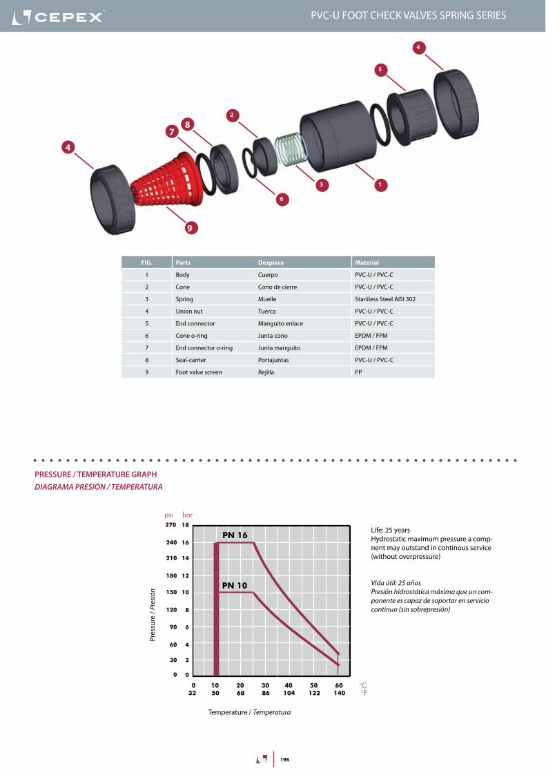
FIG. Parts Despiece Material
1 Body Cuerpo PVC-U / PVC-C
2 Cone Cono de cierre PVC-U / PVC-C
3 Spring Muelle Staniless Steel AISI 302
4 Union nut Tuerca PVC-U / PVC-C
5 End connector Manguito enlace PVC-U / PVC-C
6 Cone o-ring Junta cono EPDM / FPM
7 End connector o-ring Junta manguito EPDM / FPM
8 Seal-carrier Portajuntas PVC-U / PVC-C
9 Foot valve screen Rejilla PP
1
2
4
8
5
7
3
6
9
4
20 years / water flow20 années / fluide de l�eau20 años / fluido de agua20 anos / caudal de água
18
16
14
12
10
8
6
4
2
0
0 10 20 30 40 50 60
Temperature / Température / Temperatura / Temperatura
Pres
sure
/Pre
ssio
n/ P
resió
n/ P
ress
ão
°C32 50 68 86 104 122 140 °F
barpsi270
240
210
180
150
120
90
60
30
0
DN
15
-3/8
”-½
”
DN
20
-¾
”DN
25
-1”
DN
32
-1¼
”
DN
40
-1½
”DN
50
-2”
DN
65
-2½
”
0,1
10 (l/min)
bar
Kv (l/min , p = 1 bar)
0,01
0,001
1
100 1.000 10.000
DN
80
-3”
DN
100
-4”
2,64 (GPM)26,42 264 2.642
1,50
0,15
0,01
15,0
psi
Flow / Débit / Caudal / Caudal
Pres
sure
loss
/Per
tede
char
ge/
Pérd
ida
deca
rga
/Per
dasd
eca
rga
PN 10
PN 16
PVC-U FOOT CHECK VALVES SPRINg SERIES
PreSSUre / teMPeratUre graPhdiaGraMa PreSión / TeMPeraTura
Pres
sure
/ Pr
esió
n
Temperature / Temperatura
vida útil: 25 añosPresión hidrostática máxima que un com-ponente es capaz de soportar en servicio continuo (sin sobrepresión)
Life: 25 yearsHydrostatic maximum pressure a comp-nent may outstand in continous service (without overpressure)

197
D P (bar) Minimum opening
P (bar) Maximum opening
P (PSI) Minimum opening
P (PSI) Maximum opening
20 0,11 0,19 1,57 2,71
25 0,035 0,067 0,5 0,95
32 0,042 0,077 0,6 1,1
40 0,038 0,069 0,54 0,98
50 0,063 0,088 0,9 1,25
63 0,038 0,060 0,54 0,85
75 0,031 0,060 0,44 0,85
90 0,025 0,060 0,35 0,85
OPening PreSSUrePreSión de aPerTura
PreSSUre lOSS DiagraMdiaGraMa de PÉrdidaS de carGa
D16 - ⅜“ D20 - ½” D25 - ¾” D32 - 1” D40 - 1¼” D50 - 1½” D63 - 2” D75 - 2½” D90 - 3” D110 - 4”
A B A B A B A B A B A B A B A B A B A B
0,42 0,34 0,44 0,34 0,54 0,17 0,35 0,13 3,15 0,13 25,85 0,38 39,80 0,70 50,00 0,40 83,50 0,45 77,2 0,46
0,85 0,52 0,92 0,58 1,06 0,22 1,13 0,18 5,20 0,12 20,70 0,27 34,50 0,48 44,20 0,29 74,80 0,39 67,5 0,36
1,35 0,58 1,60 0,19 1,65 0,15 1,62 0,15 7,35 0,16 17,50 0,19 27,50 0,28 36,50 0,23 64,90 0,31 60,1 0,30
2,08 0,28 2,05 0,18 2,18 0,18 2,02 0,14 9,38 0,21 12,30 0,11 21,15 0,17 30,90 0,20 50,38 0,21 49,6 0,22
2,44 0,34 2,48 0,22 3,21 0,29 2,59 0,14 12,17 0,31 8,86 0,09 12,65 0,09 25,50 0,15 43,08 0,18 41,1 0,18
2,80 0,60 3,10 0,30 3,91 0,38 3,07 0,15 15,05 0,43 3,22 0,09 6,25 0,08 20,35 0,12 35,22 0,14 31,5 0,14
- - 3,53 0,35 4,32 0,44 3,51 0,16 - - - - - - 12,30 0,11 28,75 0,11 24,6 0,13
- - - - - - 4,20 0,20 - - - - - - 6,27 0,11 18,02 0,08 15,8 0,01
- - - - - - - - - - - - - - - - 8,28 0,11 7,9 0,08
- - - - - - - - - - - - - - - - - - - -
A = Flow (m3/h) caudal (m3/h)
B = Pressure loss (bar) Pérdida de carga (bar)
PVC-U FOOT CHECK VALVES SPRINg SERIES
Minimum pressure: opening startMaximum pressure: fully open valve
Presión mínima: inicio aperturaPresión máxima: válvula completamente abierta

198
D DN PN REF. CODE16 10 16 05 66 016 08990
20 15 16 05 66 020 08991
25 20 16 05 66 025 08992
32 25 16 05 66 032 08993
40 32 16 05 66 040 08994
50 40 16 05 66 050 08995
63 50 16 05 66 063 08996
75 65 10 05 66 075 08997
90 80 10 05 66 090 08998
110 80 10 05 66 110 08999
L H E14 107 52
16 107 52
19 130 62
22 154 70
26 176 84
31 202 94
38 239 117
44 306 148
51 362 179
61 367 179
G DN PN REF. CODE.⅜” 10 16 05 66 616 09000
½” 15 16 05 66 620 09001
¾” 20 16 05 66 625 09002
1” 25 16 05 66 632 09003
1¼” 32 16 05 66 640 09004
1½” 40 16 05 66 650 09005
2” 50 16 05 66 663 09006
2½” 65 10 05 66 675 09007
3” 80 10 05 66 690 09008
4” 80 10 05 66 710 09009
L H E14 107 52
16 107 52
19 130 62
22 154 70
26 176 84
31 202 94
38 239 117
44 306 148
51 362 179
61 367 179
D DN PN REF. CODE16 10 16 05 66 016 VI 18731
20 15 16 05 66 020 VI 18732
25 20 16 05 66 025 VI 18733
32 25 16 05 66 032 VI 18734
40 32 16 05 66 040 VI 18735
50 40 16 05 66 050 VI 18736
63 50 16 05 66 063 VI 18737
75 65 10 05 66 075 VI 18738
90 80 10 05 66 090 VI 18739
110 80 10 05 66 110 VI 18740
L H E14 107 52
16 107 52
19 130 62
22 154 70
26 176 84
31 202 94
38 239 117
44 306 148
51 362 179
61 367 179
G DN PN REF. CODE⅜” 10 16 05 66 616 VI 18741
½” 15 16 05 66 620 VI 18742
¾” 20 16 05 66 625 VI 18743
1” 25 16 05 66 632 VI 18744
1¼” 32 16 05 66 640 VI 18745
1½” 40 16 05 66 650 VI 18746
2” 50 16 05 66 663 VI 18747
2½” 65 10 05 66 675 VI 18748
3” 80 10 05 66 690 VI 18749
4” 80 10 05 66 710 VI 18750
L H E14 107 52
16 107 52
19 130 62
22 154 70
26 176 84
31 202 94
38 239 117
44 306 148
51 362 179
61 367 179
D E
L
H
D E
L
H
G E
L
H
G E
L
H
Válvula de pie• Cuerpo en PVC-U• Encolar hembra• Serie métrica• Anillos tóricos en EPDM
Foot valve• PVC-U body• Female solvent socket• Metric series• O-Rings in EPDM
UP-S. 66. SF1 - SPRINg FOOT CHECK VALVE
Válvula de pie• Cuerpo en PVC-U• Roscar hembra BSP• Anillos tóricos en EPDM
Foot valve• PVC-U body• BSP female thread• O-Rings in EPDM
UP-S. 66. FT1 - SPRINg FOOT CHECK VALVE
Válvula de pie• Cuerpo en PVC-U• Encolar hembra• Serie métrica• Anillos tóricos en FPM
Foot valve• PVC-U body• Female solvent socket• Metric series• O-Rings in FPM
UP-S. 66. SF4 - SPRINg FOOT CHECK VALVE
Válvula de pie• Cuerpo en PVC-U• Roscar hembra BSP• Anillos tóricos en FPM
Foot valve• PVC-U body• BSP female thread• O-Rings in FPM
UP-S. 66. FT4 - SPRINg FOOT CHECK VALVE
PVC-U FOOT CHECK VALVES SPRINg SERIES

199
Pvc-U check valveS - UniBlOck SerieS válvulaS anTi-reTorno Pvc-u - Serie uniblock
Sizes Solvent cement D20 - D110 (DN15 - DN100)Threaded ½” - 4”
Standards Solvent socket - MetricThreaded - BSP
EN ISO 1452, EN ISO 15493ISO 228-1
Working pressure @ 20ºC (73ºF)
D20-D63 (½” - 2”): PN 16 (240 psi)D75 - D110 (2½” - 4”): PN 10 (150 psi)
Minimum working pressure
Materials O-rings: EPDM
Characteristics • May be used either vertically and horizontally.• 100% factory tested.• Easy installation and maintenance.• Available in PVC-U.• Resistance to many inorganic chemicals.• Excellent flow characteristics.
• Se pueden usar indistintamente verticalmente o horizontalmente.• Probadas al 100% en fábrica.• Fácil instalación y mantenimiento.• Disponibles en PVC-U.• Resistencia a múltiples substancias químicas inorgánicas.• Excelentes características de conducción.
Certifications / regulations Check valve design regulation - ISO 16137:2006
PVC-U CHECK VALVES UNIBLOCK SERIES
200
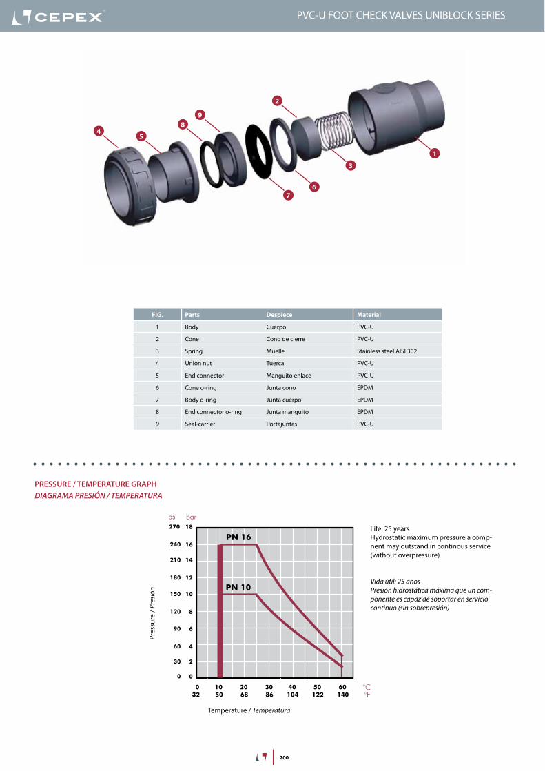
FIG. Parts Despiece Material
1 Body Cuerpo PVC-U
2 Cone Cono de cierre PVC-U
3 Spring Muelle Stainless steel AISI 302
4 Union nut Tuerca PVC-U
5 End connector Manguito enlace PVC-U
6 Cone o-ring Junta cono EPDM
7 Body o-ring Junta cuerpo EPDM
8 End connector o-ring Junta manguito EPDM
9 Seal-carrier Portajuntas PVC-U
1
2
4
7
9
5
8
3
6
20 years / water flow20 années / fluide de l�eau20 años / fluido de agua20 anos / caudal de água
18
16
14
12
10
8
6
4
2
0
0 10 20 30 40 50 60
Temperature / Température / Temperatura / Temperatura
Pres
sure
/Pre
ssio
n/ P
resió
n/ P
ress
ão
°C32 50 68 86 104 122 140 °F
barpsi270
240
210
180
150
120
90
60
30
0
DN
15
-3/8
”-½
”
DN
20
-¾
”DN
25
-1”
DN
32
-1¼
”
DN
40
-1½
”DN
50
-2”
DN
65
-2½
”
0,1
10 (l/min)
bar
Kv (l/min , p = 1 bar)
0,01
0,001
1
100 1.000 10.000
DN
80
-3”
DN
100
-4”
2,64 (GPM)26,42 264 2.642
1,50
0,15
0,01
15,0
psi
Flow / Débit / Caudal / Caudal
Pres
sure
loss
/Per
tede
char
ge/
Pérd
ida
deca
rga
/Per
dasd
eca
rga
PN 10
PN 16
PVC-U FOOT CHECK VALVES UNIBLOCK SERIES
PreSSUre / teMPeratUre graPhdiaGraMa PreSión / TeMPeraTura
Pres
sure
/ Pr
esió
n
Temperature / Temperatura
vida útil: 25 añosPresión hidrostática máxima que un com-ponente es capaz de soportar en servicio continuo (sin sobrepresión)
Life: 25 yearsHydrostatic maximum pressure a comp-nent may outstand in continous service (without overpressure)

201
D P (bar) Minimum opening
P (bar) Maximum opening
P (psi) Minimum opening
P (psi) Maximum opening
20 0,11 0,19 1,57 2,71
25 0,035 0,067 0,5 0,95
32 0,042 0,077 0,6 1,1
40 0,038 0,069 0,54 0,98
50 0,063 0,088 0,9 1,25
63 0,038 0,060 0,54 0,85
75 0,031 0,060 0,44 0,85
90 0,025 0,060 0,35 0,85
OPening PreSSUrePreSión de aPerTura
Pres
sure
loss
/ Per
tede
char
ge/
Pérd
ida
deca
rga
/ Per
das d
eca
rga
Flow / Débit / Caudal / Caudal
100 1.000 10.000
1
mca
(l/min)
10
26,4 264 2.642 (GPM)
1,5
psi
15
10
Temperature / Température / Temperatura / Temperatura
20 years / water flow20 années / fluide de l�eau20 años / fluido de agua20 anos / caudal de água
Pres
sure
/Pre
ssio
n/ P
resió
n/ P
ress
ão
18
16
14
12
10
8
6
4
2
0
0 10 20 30 40 50 60 70 80 90 °C32 50 68 86 104 122 140 158 176 194 °F
barpsi
PVC -U
PVC-C
270
240
210
180
150
120
90
60
30
0
PN 16 (240 psi)
PN 10 (150 psi)
D20
-½
”D25
-¾
”D32
-1”
D40
-1¼
”D50
-1½
”
D63
-2”
D75
-2½
”
D90
-3”
D110
-4”
D16
-3/8
”0
PVC-U CHECK VALVES UNIBLOCK SERIES
PreSSUre lOSS DiagraMdiaGraMa de PÉrdidaS de carGa
Pres
sure
loss
/ Pé
rdid
a de
carg
a
Flow / caudal
Minimum pressure: opening startMaximum pressure: fully open valve
Presión mínima: inicio aperturaPresión máxima: válvula completamente abierta
FIG. Parts Despiece Material
1 Body Cuerpo PVC-U
2 Cone Cono de cierre PVC-U
3 Spring Muelle Stainless steel AISI 302
4 Union nut Tuerca PVC-U
5 End connector Manguito enlace PVC-U
6 Cone o-ring Junta cono EPDM
7 Body o-ring Junta cuerpo EPDM
8 End connector o-ring Junta manguito EPDM
9 Seal-carrier Portajuntas PVC-U
bar
1
0,1
D 20-½” 25-¾” 32-1” 40-1¼” 50-1½” 63-2” 75-2½” 90 - 3” 110- 4”
DN 15 20 25 32 40 50 65 80 100
Kv100 68 133 208 383 667 850 1533 1160 1200
Cv 5 9 15 27 47 60 107 81,2 84
relative FlOWFluJo relaTivo
Cv = Kv100 / 14,28Kv100 (l/min, ∆p = 1 bar)Cv (GPM, ∆p = 1 psi)
Relative flow in fully open valve (maximum opening)Flujo relativo en válvula completamente abierta (apertura máxima)

202
D DN PN REF. CODE20 15 16 05 93 020 36559
25 20 16 05 93 025 36560
32 25 16 05 93 032 36561
40 32 16 05 93 040 36562
50 40 16 05 93 050 36563
63 50 16 05 93 063 36564
75 65 10 05 93 075 36565
90 80 10 05 93 090 36566
110 80 10 05 93 111 36567
L H E16 81 52
19 103 60
22 117 69
26 135 84
31 135 94
38 169 116
44 220 128
51 256 178
63 331 228
G DN PN REF. CODE½” 15 16 05 93 620 36568
¾” 20 16 05 93 625 36569
1” 25 16 05 93 632 36570
1¼” 32 16 05 93 640 36571
1½” 40 16 05 93 650 36572
2” 50 16 05 93 663 36573
2½” 65 10 05 93 675 36574
3” 80 10 05 93 690 36575
4” 80 10 05 93 711 36576
L H E16 85 52
19 103 60
19 117 69
23 135 84
31 135 94
34 169 116
44 220 128
51 256 178
63 331 228
Válvula anti-retorno Uniblock• Cuerpo en PVC-U• Encolar hembra• Serie métrica• Anillos tóricos en EPDM
Uniblock check valve• PVC-U body• Female solvent socket• Metric series• O-rings in EPDM
UP-B. 67. SF1 - UNIBLOCK CHECK VALVE
Válvula anti-retorno Uniblock• Cuerpo en PVC-U• Roscar hembra BSP• Anillos tóricos en EPDM
Uniblock check valve• PVC-U body• BSP female thread• O-Rings in EPDM
UP-B. 67. FT1 - UNIBLOCK CHECK VALVE
H
L
DE
H
L
GE
PVC-U FOOT CHECK VALVES UNIBLOCK SERIES

203
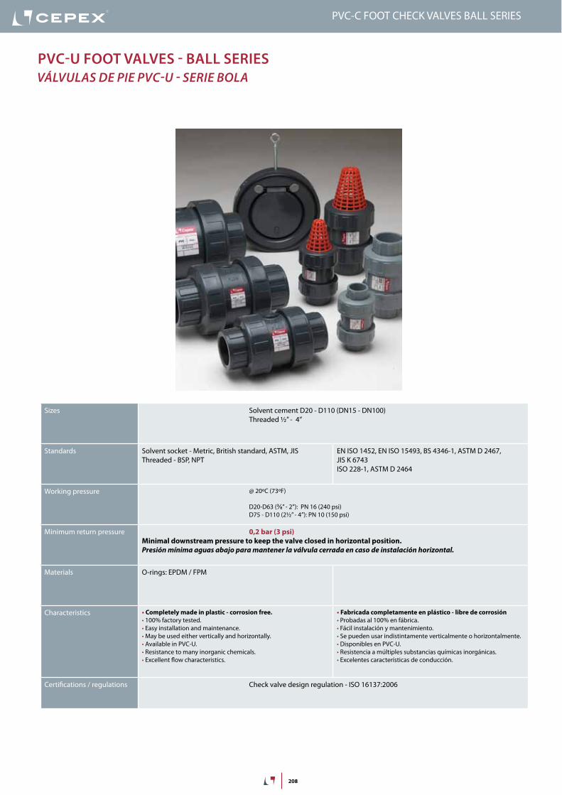
Pvc-U check valveS - Ball SerieS válvulaS anTi-reTorno Pvc-u - Serie bola
Sizes Solvent cement D20 - D110 (DN15 - DN100)Threaded ½” - 4”
Standards Solvent socket - Metric, British standard, ASTM, JISThreaded - BSP, NPT
EN ISO 1452, EN ISO 15493, BS 4346-1, ASTM D 2467, JIS K 6743ISO 228-1, ASTM D 2464
Working pressure @ 20ºC (73ºF)
D20-D63 (½” - 2”): PN 16 (240 psi)D75 - D110 (2½” - 4”): PN 10 (150 psi)
Minimum return pressure 0,2 bar (3 psi)Minimal downstream pressure to keep the valve closed in horizontal position.Presión mínima aguas abajo para mantener la válvula cerrada en caso de instalación horizontal.
Materials O-rings: EPDM / FPM
Characteristics • Completely made in plastic - corrosion free.• 100% factory tested.• Excellent flow rate.• Easy installation and maintenance.• May be used either vertically and horizontally.• Available in PVC-U and Corzan® PVC-C.• Resistance to many inorganic chemicals.• Excellent flow characteristics.
• Fabricada completamente en plástico - libre de corrosión.• Probadas al 100% en fábrica.• Excelente coeficiente de caudal.• Fácil instalación y mantenimiento.• Se pueden usar indistintamente verticalmente o horizontalmente.• Disponibles en PVC-U y Corzan® PVC-C.• Resistencia a múltiples substancias químicas inorgánicas.• Excelentes características de conducción.
Certifications / regulations Check valve design regulation - ISO 16137:2006
PVC-U CHECK VALVES BALL SERIES

204
FIG. Parts Despiece Material
1 Body Cuerpo PVC-U
3 Ball Bola PVC-U
4 Union nut Tuerca PVC-U
5 End connector Manguito enlace PVC-U
6 Closing ring Anillo de cierre PVC-U
7 Body o-ring Junta cuerpo EPDM / FPM
8 End connector o-ring Junta manguito EPDM / FPM
9 Seal-carrier Portajuntas PVC-U
14
7
9
58
3
6
4
5
PVC-U FOOT CHECK VALVES BALL SERIES
20 years / water flow20 années / fluide de l�eau20 años / fluido de agua20 anos / caudal de água
18
16
14
12
10
8
6
4
2
0
0 10 20 30 40 50 60
Temperature / Température / Temperatura / Temperatura
Pres
sure
/Pre
ssio
n/ P
resió
n/ P
ress
ão
°C32 50 68 86 104 122 140 °F
barpsi270
240
210
180
150
120
90
60
30
0
DN
15
-3/8
”-½
”
DN
20
-¾
”DN
25
-1”
DN
32
-1¼
”
DN
40
-1½
”DN
50
-2”
DN
65
-2½
”
0,1
10 (l/min)
bar
Kv (l/min , p = 1 bar)
0,01
0,001
1
100 1.000 10.000
DN
80
-3”
DN
100
-4”
2,64 (GPM)26,42 264 2.642
1,50
0,15
0,01
15,0
psi
Flow / Débit / Caudal / Caudal
Pres
sure
loss
/Per
tede
char
ge/
Pérd
ida
deca
rga
/Per
dasd
eca
rga
PN 10
PN 16
PreSSUre / teMPeratUre graPhdiaGraMa PreSión / TeMPeraTura
Pres
sure
/ Pr
esió
n
Temperature / Temperatura
vida útil: 25 añosPresión hidrostática máxima que un com-ponente es capaz de soportar en servicio continuo (sin sobrepresión)
Life: 25 yearsHydrostatic maximum pressure a comp-nent may outstand in continous service (without overpressure)

205
OpenAbierto
ClosedCerrado
Temperature / Température / Temperatura / Temperatura
20 years / water flow20 années / fluide de l�eau20 años / fluido de agua20 anos / caudal de água
Pres
sure
/Pre
ssio
n/ P
resió
n/ P
ress
ão
18
16
14
12
10
8
6
4
2
0
0 10 20 30 40 50 60 70 80 90 °C32 50 68 86 104 122 140 158 176 194 °F
barpsi
PVC -U
PVC -C
270
240
210
180
150
120
90
60
30
0
PN 16 (240 psi)
PN 10 (150 psi)
Pres
sure
loss
/ Per
tede
char
ge/
Pérd
ida
deca
rga
/ Per
das d
eca
rga
Flow / Débit / Caudal / Caudal
100 1.000 10.000
1
mca
(l/min)
10
26,4 264 2.642 (GPM)
1,5
psi
15
10D20
-½
”
D25
-¾
”D32
-1”
D40
-1¼
”
D50
-1½
”
D63
-2”
D75
-2½
”
D90
-3”
0
relative FlOWFluJo relaTivo
D 20-½” 25-¾” 32-1” 40-1¼” 50-1½” 63-2” 75-2½” 90-3”
DN 15 20 25 32 40 50 65 80
Kv100 99 128 308 453 795 1040 1932 2754
Cv 7 9 22 32 56 73 135 193
PVC-U CHECK VALVES BALL SERIES
PreSSUre lOSS DiagraMdiaGraMa de PÉrdidaS de carGa
Pres
sure
loss
/ Pé
rdid
a de
carg
a
Flow / caudal
Cv = Kv100 / 14,28Kv100 (l/min, ∆p = 1 bar)Cv (GPM, ∆p = 1 psi)
bar
1
0,1

206
inStrUcciOneS De MOntaje
Uniones encoladas o roscadasAfloje las tuercas (4) de la válvula y sepárelas de los manguitos (5). Introduzca las tuercas en los tubos y a continuación fije los manguitos en los extremos del tubo. Las uniones encoladas se realizarán con un adhesivo para tubos de PVC-U o PVC-C rígido y no se aplicará presión hasta transcurridas al menos 1 hora por bar. En las uniones roscadas se colocará cinta de PTFE en las roscas macho. A continuación ya podrá colocarse la válvula entre los manguitos y apretar a mano las tuercas sobre la válvula.
aSSeMBly inStrUctiOnS
Solvent socket or threaded unionsLoosen the valve union nuts (4) and separate these and the end connectors (5) from the valve body. Pass the pipe through the nuts and then place the bushes over the end of the pipe. The socket unions should be guied onto the pipe using a PVC-U or PVC-C adhesive and pressure should not be applied to the system until a drying period of at least 1 hour per bar of working pressure has elapsed. In the case of threaded unions, PTFE tape should be applied to the male threads. The pipes can now be attached to the valve by hand tightening down the nuts.
1
2
3
4
5
PVC-U FOOT CHECK VALVES BALL SERIES

207
D DN PN REF. CODE20 15 16 05 67 220 22078
25 20 16 05 67 225 22079
32 25 16 05 67 232 22080
40 32 16 05 67 240 22174
50 40 16 05 67 250 25697
63 50 16 05 67 263 25698
75 65 10 05 67 275 22175
90 80 10 05 67 290 22176
110 80 10 05 67 310 22177
L H E16 84 52
19 108 62
22 119 70
26 142 84
31 162 94
38 192 117
44 232 148
51 269 179
51 269 179
G DN PN REF. CODE½” 15 16 05 67 420 22061
¾” 20 16 05 67 425 22062
1” 25 16 05 67 432 22085
1¼” 32 16 05 67 440 22086
1½” 40 16 05 67 450 25699
2” 50 16 05 67 463 25700
2½” 65 10 05 67 475 22087
3” 80 10 05 67 490 22088
4” 80 10 05 67 510 22089
L H E16 84 52
19 108 62
22 119 70
26 142 84
31 167 94
38 192 117
44 232 148
51 269 179
61 279 179
D DN PN REF. CODE20 15 16 05 67 220 VI 22090
25 20 16 05 67 225 VI 22091
32 25 16 05 67 232 VI 22092
40 32 16 05 67 240 VI 22239
50 40 16 05 67 250 VI 25701
63 50 16 05 67 263 VI 25702
75 65 10 05 67 275 VI 22240
90 80 10 05 67 290 VI 22241
110 80 10 05 67 310 VI 22242
L H E16 84 52
19 108 62
22 119 70
26 142 84
31 162 94
38 192 117
44 232 148
51 269 179
51 269 179
G DN PN REF. CODE½” 15 16 05 67 420 VI 22243
¾” 20 16 05 67 425 VI 22244
1” 25 16 05 67 432 VI 22267
1¼” 32 16 05 67 440 VI 22268
1½” 40 16 05 67 450 VI 25703
2” 50 16 05 67 463 VI 25704
2½” 65 10 05 67 475 VI 22269
3” 80 10 05 67 490 VI 22270
4” 80 10 05 67 510 VI 22893
L H E16 84 52
19 108 62
22 119 70
26 142 84
31 167 94
38 192 117
44 232 148
51 269 179
61 279 179
D
LL
EH
D
LL
E
H
G
LL
E
H
G
LL
E
H
Válvula anti-retorno de bola• Cuerpo en PVC-U• Encolar hembra• Serie métrica• Anillos tóricos en EPDM
Ball check valve• PVC-U body• Female solvent socket• Metric series• O-rings in EPDM
UP-B. 67. SF1 - BALL CHECK VALVE
Válvula anti-retorno de bola• Cuerpo en PVC-U• Roscar hembra BSP• Anillos tóricos en EPDM
Ball check valve• PVC-U body• BSP female thread• O-Rings in EPDM
UP-B. 67. FT1 - BALL CHECK VALVE
Válvula anti-retorno de bola• Cuerpo en PVC-U• Encolar hembra• Serie métrica• Anillos tóricos en FPM
Ball check valve• PVC-U body• Female solvent socket• Metric series• O-Rings in FPM
UP-B. 67. SF4 - BALL CHECK VALVE
Válvula anti-retorno de bola• Cuerpo en PVC-U• Roscar hembra BSP• Anillos tóricos en FPM
Ball check valve• PVC-U body• BSP female thread• O-Rings in FPM
UP-B. 67. FT4 - BALL CHECK VALVE
PVC-U CHECK VALVES BALL SERIES
208
Pvc-U FOOt valveS - Ball SerieS válvulaS de Pie Pvc-u - Serie bola
Sizes Solvent cement D20 - D110 (DN15 - DN100)Threaded ½” - 4”
Standards Solvent socket - Metric, British standard, ASTM, JISThreaded - BSP, NPT
EN ISO 1452, EN ISO 15493, BS 4346-1, ASTM D 2467, JIS K 6743ISO 228-1, ASTM D 2464
Working pressure @ 20ºC (73ºF)
D20-D63 (⅜” - 2”): PN 16 (240 psi)D75 - D110 (2½” - 4”): PN 10 (150 psi)
Minimum return pressure 0,2 bar (3 psi)Minimal downstream pressure to keep the valve closed in horizontal position.Presión mínima aguas abajo para mantener la válvula cerrada en caso de instalación horizontal.
Materials O-rings: EPDM / FPM
Characteristics • Completely made in plastic - corrosion free.• 100% factory tested.• Easy installation and maintenance.• May be used either vertically and horizontally.• Available in PVC-U.• Resistance to many inorganic chemicals.• Excellent flow characteristics.
• Fabricada completamente en plástico - libre de corrosión• Probadas al 100% en fábrica.• Fácil instalación y mantenimiento.• Se pueden usar indistintamente verticalmente o horizontalmente.• Disponibles en PVC-U.• Resistencia a múltiples substancias químicas inorgánicas.• Excelentes características de conducción.
Certifications / regulations Check valve design regulation - ISO 16137:2006
PVC-C FOOT CHECK VALVES BALL SERIES

209
FIG. Parts Despiece Material
1 Body Cuerpo PVC-U
3 Ball Bola PVC-U
4 Union nut Tuerca PVC-U
5 End connector Manguito enlace PVC-U
6 Closing ring Anillo de cierre PVC-U
7 Body o-ring Junta cuerpo EPDM / FPM
8 End connector o-ring Junta manguito EPDM / FPM
9 Seal-carrier Portajuntas PVC-U
10 Foot valve screen Rejilla PP
1
4
7
98
3
6
10
4
5
PVC-C FOOT CHECK VALVES BALL SERIES
20 years / water flow20 années / fluide de l�eau20 años / fluido de agua20 anos / caudal de água
18
16
14
12
10
8
6
4
2
0
0 10 20 30 40 50 60
Temperature / Température / Temperatura / Temperatura
Pres
sure
/Pre
ssio
n/ P
resió
n/ P
ress
ão
°C32 50 68 86 104 122 140 °F
barpsi270
240
210
180
150
120
90
60
30
0
DN
15
-3/8
”-½
”
DN
20
-¾
”DN
25
-1”
DN
32
-1¼
”
DN
40
-1½
”DN
50
-2”
DN
65
-2½
”
0,1
10 (l/min)
bar
Kv (l/min , p = 1 bar)
0,01
0,001
1
100 1.000 10.000
DN
80
-3”
DN
100
-4”
2,64 (GPM)26,42 264 2.642
1,50
0,15
0,01
15,0
psi
Flow / Débit / Caudal / Caudal
Pres
sure
loss
/Per
tede
char
ge/
Pérd
ida
deca
rga
/Per
dasd
eca
rga
PN 10
PN 16
PreSSUre / teMPeratUre graPhdiaGraMa PreSión / TeMPeraTura
Pres
sure
/ Pr
esió
n
Temperature / Temperatura
vida útil: 25 añosPresión hidrostática máxima que un com-ponente es capaz de soportar en servicio continuo (sin sobrepresión)
Life: 25 yearsHydrostatic maximum pressure a comp-nent may outstand in continous service (without overpressure)

210
PreSSUre lOSS DiagraMdiaGraMa de PÉrdidaS de carGa
D20 - ½” D25 - ¾” D32 - 1” D40 - 1¼” D50 - 1½” D63 - 2” D75 - 2½” D90 - 3”
A B A B A B A B A B A B A B A B
1,65 0,13 1,47 0,05 4,36 0,08 4,87 0,15 6,41 0,002 12,53 0,05 12,32 0,05 7,13 0,009
2,33 0,24 2,01 0,054 4,89 0,11 6,21 0,17 11,3 0,02 14,9 0,07 14,95 0,06 15,91 0,04
3,34 0,44 2,34 0,09 5,44 0,15 7,52 0,21 18,76 0,16 17,12 0,11 19,53 0,11 28,58 0,13
3,85 0,52 2,95 0,18 5,89 0,21 10,61 0,27 25,05 0,34 21,7 0,16 25 0,17 37,22 0,22
4,52 0,69 3,6 0,29 7,01 0,26 12,53 0,34 28,44 0,41 27,36 0,28 32,6 0,28 45,61 0,53
- - 4,03 0,36 9,23 0,39 15,23 0,4 - - 32,02 0,37 41,43 0,55 58,5 0,64
- - 4,21 0,38 - - - - - - 37,68 0,43 - - - -
A = Flow (m3/h) caudal (m3/h)
B = Pressure loss (bar) Pérdida de carga (bar)
PVC-C FOOT CHECK VALVES BALL SERIES

211
D DN PN REF. CODE20 15 16 05 66 220 27537
25 20 16 05 66 225 27538
32 25 16 05 66 232 27539
40 32 16 05 66 240 27540
50 40 16 05 66 250 25705
63 50 16 05 66 263 25706
75 65 10 05 66 275 27543
90 80 10 05 66 290 27544
110 80 10 05 66 310 27545
L H E16 107 52
19 130 62
22 154 70
26 176 84
31 202 94
38 239 117
44 306 148
51 362 179
61 367 179
G DN PN REF. CODE½” 15 16 05 66 420 27546
¾” 20 16 05 66 425 27547
1” 25 16 05 66 432 27548
1¼” 32 16 05 66 440 27549
1½” 40 16 05 66 450 25707
2” 50 16 05 66 463 25708
2½” 65 10 05 66 475 27552
3” 80 10 05 66 490 27553
4” 80 10 05 66 510 27554
L H E16 107 52
19 130 62
22 154 70
26 176 84
31 202 94
38 239 117
44 306 148
51 362 179
61 367 179
D DN PN REF. CODE20 15 16 05 66 220 VI 27555
25 20 16 05 66 225 VI 27556
32 25 16 05 66 232 VI 27557
40 32 16 05 66 240 VI 27558
50 40 16 05 66 250 VI 25709
63 50 16 05 66 263 VI 25710
75 65 10 05 66 275 VI 27561
90 80 10 05 66 290 VI 27562
110 80 10 05 66 310 VI 27563
L H E16 107 52
19 130 62
22 154 70
26 176 84
31 202 94
38 239 117
44 306 148
51 362 179
61 367 179
G DN PN REF. CODE½” 15 16 05 66 420 VI 27564
¾” 20 16 05 66 425 VI 27565
1” 25 16 05 66 432 VI 27566
1¼” 32 16 05 66 440 VI 27567
1½” 40 16 05 66 450 VI 25711
2” 50 16 05 66 463 VI 25712
2½” 65 10 05 66 475 VI 27570
3” 80 10 05 66 490 VI 27571
4” 80 10 05 66 510 VI 27572
L H E16 107 52
19 130 62
22 154 70
26 176 84
31 202 94
38 239 117
44 306 148
51 362 179
61 367 179
L
D E
H
L
D E
H
L
G E
H
L
G E
H
Válvula de pie de bola• Cuerpo en PVC-U• Encolar hembra• Serie métrica• Anillos tóricos en EPDM
Ball foot valve• PVC-U body• Female solvent socket• Metric series• O-Rings in EPDM
UP-B. 66. SF1 - BALL FOOT CHECK VALVES
Válvula de pie de bola• Cuerpo en PVC-U• Roscar hembra BSP• Anillos tóricos en EPDM
Ball foot valve• PVC-U body• BSP female thread• O-Rings in EPDM
UP-B. 66. FT1 - BALL FOOT CHECK VALVES
Válvula de pie de bola• Cuerpo en PVC-U• Encolar hembra• Serie métrica• Anillos tóricos en FPM
Ball foot valve• PVC-U body• Female solvent socket• Metric series• O-Rings in FPM
UP-B. 66. SF4 - BALL FOOT CHECK VALVES
Válvula de pie de bola• Cuerpo en PVC-U• Roscar hembra BSP• Anillos tóricos en FPM
Ball foot valve• PVC-U body• BSP female thread• O-Rings in FPM
UP-B. 66. FT4 - BALL FOOT CHECK VALVES
PVC-C FOOT CHECK VALVES BALL SERIES
212
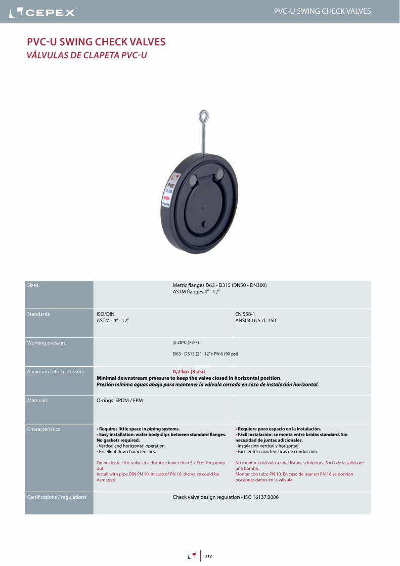
Pvc-U SWing check valveS válvulaS de claPeTa Pvc-u
Sizes Metric flanges D63 - D315 (DN50 - DN300)ASTM flanges 4” - 12”
Standards ISO/DINASTM - 4” - 12”
EN 558-1ANSI B.16.5 cl. 150
Working pressure @ 20ºC (73ºF)
D63 - D315 (2” - 12”): PN 6 (90 psi)
Minimum return pressure 0,2 bar (3 psi)Minimal downstream pressure to keep the valve closed in horizontal position.Presión mínima aguas abajo para mantener la válvula cerrada en caso de instalación horizontal.
Materials O-rings: EPDM / FPM
Characteristics • Requires little space in piping systems.• Easy installation: wafer body slips between standard flanges. No gaskets required.• Vertical and horitzontal operation.• Excellent flow characteristics.
Do not install the valve at a distance lower than 5 x D of the pump out.Install with pipe DIN PN 10. In case of PN 16, the valve could be damaged.
• Requiere poco espacio en la instalación.• Fácil instalación: se monta entre bridas standard. Sin necesidad de juntas adicionales.• Instalación vertical y horizontal.• Excelentes características de conducción.
No montar la válvula a una distancia inferior a 5 x D de la salida de una bomba.Montar con tubo PN 10. En caso de usar un PN 16 se podrían ocasionar daños en la válvula.
Certifications / regulations Check valve design regulation - ISO 16137:2006
PVC-U SWINg CHECK VALVES

213
FIG. Parts Despiece Material
1 Body Cuerpo PVC-U
2 Flap Clapeta PVC-U
3 Cap Tapón PP
4 Body O-ring Junta cuerpo EPDM / FPM
5 Flap O-ring Junta clapeta EPDM / FPM
1
2
4
5
3
4
PVC-U SWINg CHECK VALVES
20 years / water flow20 années / fluide de l�eau20 años / fluido de agua20 anos / caudal de água
18
16
14
12
10
8
6
4
2
0
0 10 20 30 40 50 60
Pres
sure
/ Pre
ssio
n/ P
resió
n/ P
ress
ão
°C32 50 68 86 104 122 140 °F
barpsi270
240
210
180
150
120
90
60
30
0
DN
65
-2½
”
DN
80
-3”
DN
100
-4”
DN
110
-4½
”
DN
125
-5”
DN
150
-6”
DN
175
-7”
DN
200
-8”
1
0.1
0.0110 100 1.000
Flow / Débit / Caudal / Caudal
15
1.5
0.15
barpsi
m3/hft3/min5,88 58,8 588
Temperature / Température / Temperatura / Temperatura
Pres
sure
loss
/Per
tede
char
ge/
Pérd
ida
deca
rga
/ Per
dade
carg
a
PN 6 (90 psi)
D50
-½
”
DN
250
-9”
DN
300
-12”
PreSSUre / teMPeratUre graPhdiaGraMa PreSión / TeMPeraTura
Pres
sure
/ Pr
esió
n
Temperature / Temperatura
vida útil: 25 añosPresión hidrostática máxima que un com-ponente es capaz de soportar en servicio continuo (sin sobrepresión)
Life: 25 yearsHydrostatic maximum pressure a comp-nent may outstand in continous service (without overpressure)

214
20 years / water flow20 années / fluide de l�eau20 años / fluido de agua20 anos / caudal de água
18
16
14
12
10
8
6
4
2
0
0 10 20 30 40 50 60
Pres
sure
/ Pre
ssio
n/ P
resió
n/ P
ress
ão
°C32 50 68 86 104 122 140 °F
barpsi270
240
210
180
150
120
90
60
30
0
DN
65
-2½
”
DN
80
-3”
DN
100
-4”
DN
110
-4½
”
DN
125
-5”
DN
150
-6”
DN
175
-7”
DN
200
-8”
1
0.1
0.0110 100 1.000
Flow / Débit / Caudal / Caudal
15
1.5
0.15
barpsi
m3/hft3/min5,88 58,8 588
Temperature / Température / Temperatura / Temperatura
Pres
sure
loss
/Per
tede
char
ge/
Pérd
ida
deca
rga
/ Per
dade
carg
a
PN 6 (90 psi)
D50
-½
”
DN
250
-9”
DN
300
-12”
PVC-U SWINg CHECK VALVES
PreSSUre lOSS DiagraM
diaGraMa de PÉrdidaS de carGa
Pres
sure
loss
/ Pé
rdid
a de
carg
a
Flow / caudal
relative FlOWFluJo relaTivo
D 63 75 90 110 125 140 160 200 225 250 280 315
DN 50 65 80 100 125 125 150 175 200 250 250 300
Kv100 57 85 130 200 390 480 600 800 900 1.600 1.600 1.850
Cv 4,0 6,0 9,1 14,0 27,3 33,6 42,0 56,0 63,0 112,0 112,0 129,6
Cv = Kv100 / 14,28Kv100 (l/min, ∆p = 1 bar)Cv (GPM, ∆p = 1 psi)

215
D DN PN REF. CODE63 50 6 05 65 063 * 37055
75 65 6 05 65 075 08984
90 80 6 05 65 090 08985
110 100 6 05 65 110 08986
125 125 6 05 65 125 09040
140 125 6 05 65 140 08987
160 150 6 05 65 160 08988
200 175 6 05 65 200 09041
225 200 6 05 65 225 08989
250 250 6 05 65 250 37056
280 250 6 05 65 280 * 41865
315 300 6 05 65 315 * 37057
A B C109 20 32
129 20 40
144 20 52
164 22 70
170 25 83
195 23 92
220 25 112
247 28 139
275 35 150
328 40 162
330 40 189
380 45 226
D DN PN REF. CODE63 50 6 05 65 063 RA * 37073
75 65 6 05 65 075 RA 23312
90 80 6 05 65 090 RA 23313
110 100 6 05 65 110 RA 23314
125 125 6 05 65 125 RA 23315
140 125 6 05 65 140 RA 23316
160 150 6 05 65 160 RA 23317
200 175 6 05 65 200 RA 23318
225 200 6 05 65 225 RA 23319
250 250 6 05 65 250 RA 37074
315 300 6 05 65 315 RA * 37075
C H E32 26 109
40 30 129
52 30 144
70 32 164
83 35 170
92 33 195
112 37 220
139 40 247
150 51 275
162 56 328
226 64 330
61 380
AC
B
Válvula de clapeta• Cuerpo en PVC-U• Anillos tóricos en EPDM
Swing check valve• PVC-U body• O-rings in EPDM
UP. 65 - SWINg CHECK VALVE
Válvula de clapeta con kit accesorios• Cuerpo en PVC-U• Anillos tóricos en EPDM• Bridas locas
Swing check valve with mounting kit• PVC-U body• O-rings in EPDM• Loose flanges
UP. 65. VKIT - SWINg CHECK VALVE KIT
PVC-U SWINg CHECK VALVES
D DN PN REF. CODE63 50 6 05 65 063 FG * 37055FG
75 65 6 05 65 075 FG 08984FG
90 80 6 05 65 090 FG 08985FG
110 100 6 05 65 110 FG 08986FG
125 125 6 05 65 125 FG 09040FG
140 125 6 05 65 140 FG 08987FG
160 150 6 05 65 160 FG 08988FG
200 175 6 05 65 200 FG 09041FG
225 200 6 05 65 225 FG 08989FG
250 250 6 05 65 250 FG 37056FG
280 250 6 05 65 280 FG* 41865FG
315 300 6 05 65 315 FG* 37057FG
A B C109 20 32
129 20 40
144 20 52
164 22 70
170 25 83
195 23 92
220 25 112
247 28 139
275 35 150
328 40 162
330 40 189
380 45 226
AC
B
Válvula de clapeta• Cuerpo en PVC-U• Anillos tóricos en EPDM perox.
Swing check valve• PVC-U body• O-rings in EPDM perox.
UP. 65. FG - SWINg CHECK VALVE
D DN PN REF. CODE63 50 6 05 65 063 VIT* 37055VI
75 65 6 05 65 075 VIT 08984VI
90 80 6 05 65 090 VIT 08985VI
110 100 6 05 65 110 VIT 08986VI
125 125 6 05 65 125 VIT 09040VI
140 125 6 05 65 140 VIT 08987VI
160 150 6 05 65 160 VIT 08988VI
200 175 6 05 65 200 VIT 09041VI
225 200 6 05 65 225 VIT 08989VI
250 250 6 05 65 250 VIT 37056VI
280 250 6 05 65 280 VIT* 41865VI
315 300 6 05 65 315 VIT* 37057VI
A B C109 20 32
129 20 40
144 20 52
164 22 70
170 25 83
195 23 92
220 25 112
247 28 139
275 35 150
328 40 162
330 40 189
380 45 226
AC
B
Válvula de clapeta• Cuerpo en PVC-U• Anillos tóricos en FPM
Swing check valve• PVC-U body• O-rings in FPM
UP. 65. VIT - SWINg CHECK VALVE

415
PVC-U CHeCk ValVes - sPrinG series VálVulas aNTi-reTorNo PVC-u - serie Muelle
PVC-U CHECK VALVES SPRING SERIES - BRITISH STANDARD
Sizes Solvent cement D16 - D110 (DN10 - DN100)Threaded ⅜” - 4”
Standards Solvent socket - Metric, British standard, ASTM, JISThreaded - BSP, NPT
EN ISO 1452, EN ISO 15493, BS 4346-1, ASTM D 2467, JIS K 6743ISO 228-1, ASTM D 2464
Working pressure @ 20ºC (73ºF)
D16-D63 (⅜” - 2”): PN 16 (240 psi)D75 - D110 (2”1/2 - 4”): PN 10 (150 psi)
Minimum working pressure
Materials O-rings: EPDM / FPM
Characteristics • May be used either vertically and horizontally.• 100% factory tested.• Easy installation and maintenance.• Available in PVC-U and Corzan® PVC-C.• Resistance to many inorganic chemicals.• Excellent flow characteristics.
• Se pueden usar indistintamente verticalmente o horizontalmente.• Probadas al 100% en fábrica.• Fácil instalación y mantenimiento.• Disponibles en PVC-U y Corzan® PVC-C.• Resistencia a múltiples substancias químicas inorgánicas.• Excelentes características de conducción.
Certifications / regulations Check valve design regulation - ISO 16137:2006

416
FIG. Parts Despiece Material
1 Body Cuerpo PVC-U
2 Cone Cono de cierre PVC-U
3 Spring Muelle Stainless Steel AISI 302 / PTFE coated *
4 Union nut Tuerca PVC-U
5 End connector Manguito enlace PVC-U
6 Cone o-ring Junta cono EPDM / FPM
7 End connector o-ring Junta manguito EPDM / FPM
8 Seal-carrier Portajuntas PVC-U
1
2
4
8
57
3
6
4
5
20 years / water flow20 années / fluide de l�eau20 años / fluido de agua20 anos / caudal de água
18
16
14
12
10
8
6
4
2
0
0 10 20 30 40 50 60
Temperature / Température / Temperatura / Temperatura
Pres
sure
/Pre
ssio
n/ P
resió
n/ P
ress
ão
°C32 50 68 86 104 122 140 °F
barpsi270
240
210
180
150
120
90
60
30
0
DN
15
-3/8
”-½
”
DN
20
-¾
”DN
25
-1”
DN
32
-1¼
”
DN
40
-1½
”DN
50
-2”
DN
65
-2½
”
0,1
10 (l/min)
bar
Kv (l/min , p = 1 bar)
0,01
0,001
1
100 1.000 10.000
DN
80
-3”
DN
100
-4”
2,64 (GPM)26,42 264 2.642
1,50
0,15
0,01
15,0
psi
Flow / Débit / Caudal / Caudal
Pres
sure
loss
/Per
tede
char
ge/
Pérd
ida
deca
rga
/Per
dasd
eca
rga
PN 10
PN 16
PressUre / TeMPeraTUre GraPHdiaGraMa PresiÓN / TeMPeraTura
Pres
sure
/ Pr
esió
n
Temperature / Temperatura
Vida útil: 25 añosPresión hidrostática máxima que un com-ponente es capaz de soportar en servicio continuo (sin sobrepresión)
Life: 25 yearsHydrostatic maximum pressure a comp-nent may outstand in continous service (without overpressure)
PVC-U CHECK VALVES SPRING SERIES - BRITISH STANDARD

417
D 20-½” 25-¾” 32-1” 40-1¼” 50-1½” 63-2” 75-2½”
DN 15 20 25 32 40 50 65
Kv100 68 133 208 383 667 850 1533
Cv 5 9 15 27 47 60 107
OpenAbierto
ClosedCerrado
D P (bar) Minimum opening
P (bar) Maximum opening
P (psi) Minimum opening
P (psi) Maximum opening
20 0,11 0,19 1,57 2,71
25 0,035 0,067 0,5 0,95
32 0,042 0,077 0,6 1,1
40 0,038 0,069 0,54 0,98
50 0,063 0,088 0,9 1,25
63 0,038 0,060 0,54 0,85
75 0,031 0,060 0,44 0,85
90 0,025 0,060 0,35 0,85
OPeninG PressUre
PresiÓN de aPerTura
Minimum pressure: opening startMaximum pressure: open valve
Minimum pressure: opening startMaximum pressure: open valve
PressUre lOss DiaGraMdiaGraMa de PÉrdidas de CarGa
relaTiVe FlOWFluJo relaTiVo
Cv = Kv100 / 14,28Kv100 (l/min, ∆p = 1 bar)Cv (GPM, ∆p = 1 psi)
PVC-U CHECK VALVES SPRING SERIES - BRITISH STANDARD
Relative flow in fully open valve (maximum opening)Flujo relativo en válvula completamente abierta (apertura máxima)
Pres
sure
loss
/ Per
tede
char
ge/
Pérd
ida
deca
rga
/ Per
das d
eca
rga
Flow / Débit / Caudal / Caudal
100 1.000 10.000
1
mca
(l/min)
10
26,4 264 2.642 (GPM)
1,5
psi
15
10
Temperature / Température / Temperatura / Temperatura
20 years / water flow20 années / fluide de l�eau20 años / fluido de agua20 anos / caudal de água
Pres
sure
/Pre
ssio
n/ P
resió
n/ P
ress
ão
18
16
14
12
10
8
6
4
2
0
0 10 20 30 40 50 60 70 80 90 °C32 50 68 86 104 122 140 158 176 194 °F
barpsi
PVC -U
PVC-C
270
240
210
180
150
120
90
60
30
0
PN 16 (240 psi)
PN 10 (150 psi)
D20
-½
”D25
-¾
”D32
-1”
D40
-1¼
”D50
-1½
”
D63
-2”
D75
-2½
”
D90
-3”
D110
-4”
D16
-3/8
”
0
Pres
sure
loss
/ Pé
rdid
a de
carg
a
Flow / Caudal
bar
1
0,1

418
PVC-U CHECK VALVES SPRING SERIES - BRITISH STANDARD
insTrUCCiOnes De MOnTaje
Uniones encoladas o roscadasAfloje las tuercas (4) de la válvula y sepárelas de los manguitos (5). Introduzca las tuercas en los tubos y a continuación fije los manguitos en los extremos del tubo. Las uniones encoladas se realizarán con un adhesivo para tubos de PVC-U o PVC-C rígido y no se aplicará presión hasta transcurridas al menos 1 hora por bar. En las uniones roscadas se colocará cinta de PTFE en las roscas macho. A continuación ya podrá colocarse la válvula entre los manguitos y apretar a mano las tuercas sobre la válvula.
asseMBly insTrUCTiOns
Solvent socket or threaded unionsLoosen the valve union nuts (4) and separate these and the end connectors (5) from the valve body. Pass the pipe through the nuts and then place the bushes over the end of the pipe. The socket unions should be guied onto the pipe using a PVC-U or PVC-C adhesive and pressure should not be applied to the system until a drying period of at least 1 hour per bar of working pressure has elapsed. In the case of threaded unions, PTFE tape should be applied to the male threads. The pipes can now be attached to the valve by hand tightening down the nuts.
1
2
3
4
5

419
L H E16 84 52
16 84 52
19 108 62
22 119 70
26 142 84
31 162 94
38 192 117
44 232 148
51 269 179
61 279 179
D DN PN REF. CODE⅜” 10 16 05 67 900 09109
½” 15 16 05 67 901 09110
¾” 20 16 05 67 902 09111
1” 25 16 05 67 903 09112
1¼” 32 16 05 67 904 09113
1½” 40 16 05 67 905 09114
2” 50 16 05 67 906 09115
2½” 65 10 05 67 075M 09017
3” 80 10 05 67 908 09117
4” 100 10 05 67 910 09118
D
LL
EH
Válvula anti-retorno• Cuerpo en PVC-U• Encolar hembra• Serie British Standard• Anillos tóricos en EPDM
Spring check valve• PVC-U body• Female solvent socket• British Standard series• O-Rings in EPDM
UP-S. 67. SF1. BS - PVC-U SPRING CHECK VALVE
PVC-U CHECK VALVES SPRING SERIES - BRITISH STANDARD
PVC-C valves on orderVálvulas en PVC-C bajo pedido

420
PVC-U FOOT ValVes - sPrinG series VálVulas de Pie PVC-u - serie Muelle
PVC-U FOOT CHECK VALVES SPRING SERIES - BRITISH STANDARD
Sizes Solvent cement D16 - D110 (DN10 - DN100)Threaded ⅜” - 4”
Standards Solvent socket - Metric, British standard, ASTM, JISThreaded - BSP, NPT
EN ISO 1452, EN ISO 15493, BS 4346-1, ASTM D 2467, JIS K 6743ISO 228-1, ASTM D 2464
Working pressure @ 20ºC (73ºF)
D16-D63 (⅜” - 2”): PN 16 (240 psi)D75 - D110 (2”1/2 - 4”): PN 10 (150 psi)
Minimum working pressure
Materials O-rings: EPDM / FPM
Characteristics • May be used either vertically and horizontally.• 100% factory tested.• Easy installation and maintenance.• Available in PVC-U and Corzan® PVC-C.• Resistance to many inorganic chemicals.• Excellent flow characteristics.
• Se pueden usar indistintamente verticalmente o horizontalmente.• Probadas al 100% en fábrica.• Fácil instalación y mantenimiento.• Disponibles en PVC-U y Corzan® PVC-C.• Resistencia a múltiples substancias químicas inorgánicas.• Excelentes características de conducción.
Certifications / regulations Check valve design regulation - ISO 16137:2006

421
FIG. Parts Despiece Material
1 Body Cuerpo PVC-U / PVC-C
2 Cone Cono de cierre PVC-U / PVC-C
3 Spring Muelle Staniless Steel AISI 302
4 Union nut Tuerca PVC-U / PVC-C
5 End connector Manguito enlace PVC-U / PVC-C
6 Cone o-ring Junta cono EPDM / FPM
7 End connector o-ring Junta manguito EPDM / FPM
8 Seal-carrier Portajuntas PVC-U / PVC-C
9 Foot valve screen Rejilla PP
1
2
4
8
5
7
3
6
9
4
20 years / water flow20 années / fluide de l�eau20 años / fluido de agua20 anos / caudal de água
18
16
14
12
10
8
6
4
2
0
0 10 20 30 40 50 60
Temperature / Température / Temperatura / Temperatura
Pres
sure
/Pre
ssio
n/ P
resió
n/ P
ress
ão
°C32 50 68 86 104 122 140 °F
barpsi270
240
210
180
150
120
90
60
30
0
DN
15
-3/8
”-½
”
DN
20
-¾
”DN
25
-1”
DN
32
-1¼
”
DN
40
-1½
”DN
50
-2”
DN
65
-2½
”
0,1
10 (l/min)
bar
Kv (l/min , p = 1 bar)
0,01
0,001
1
100 1.000 10.000
DN
80
-3”
DN
100
-4”
2,64 (GPM)26,42 264 2.642
1,50
0,15
0,01
15,0
psi
Flow / Débit / Caudal / Caudal
Pres
sure
loss
/Per
tede
char
ge/
Pérd
ida
deca
rga
/Per
dasd
eca
rga
PN 10
PN 16
PressUre / TeMPeraTUre GraPHdiaGraMa PresiÓN / TeMPeraTura
Pres
sure
/ Pr
esió
n
Temperature / Temperatura
Vida útil: 25 añosPresión hidrostática máxima que un com-ponente es capaz de soportar en servicio continuo (sin sobrepresión)
Life: 25 yearsHydrostatic maximum pressure a comp-nent may outstand in continous service (without overpressure)
PVC-U FOOT CHECK VALVES SPRING SERIES - BRITISH STANDARD

422
L H E16 107 52
16 107 52
19 130 62
22 154 70
26 176 84
31 202 94
38 239 117
44 306 148
51 362 179
61 367 179
D DN PN REF. CODE⅜” 10 16 05 66 900 09099
½” 15 16 05 66 901 09100
¾” 20 16 05 66 902 09101
1” 25 16 05 66 903 09102
1¼” 32 16 05 66 904 09103
1½” 40 16 05 66 905 09104
2” 50 16 05 66 906 09105
2½” 65 10 05 66 075M 08997
3” 80 10 05 66 908 09107
4” 100 10 05 66 910 09108
D E
L
H
Válvula de pie• Cuerpo en PVC-U• Encolar hembra• Serie British Standard• Anillos tóricos en EPDM
Foot valve• PVC-U body• Female solvent socket• British Standard series• O-Rings in EPDM
UP-S. 66. SF1. BS - PVC-U SPRING FOOT CHECK VALVE
PVC-U FOOT CHECK VALVES SPRING SERIES - BRITISH STANDARD
D P (bar) Minimum opening
P (bar) Maximum opening
P (PSI) Minimum opening
P (PSI) Maximum opening
20 0,11 0,19 1,57 2,71
25 0,035 0,067 0,5 0,95
32 0,042 0,077 0,6 1,1
40 0,038 0,069 0,54 0,98
50 0,063 0,088 0,9 1,25
63 0,038 0,060 0,54 0,85
75 0,031 0,060 0,44 0,85
90 0,025 0,060 0,35 0,85
OPeninG PressUre
PresiÓN de aPerTura
Minimum pressure: opening startMaximum pressure: open valve
Minimum pressure: opening startMaximum pressure: open valve
PressUre lOss DiaGraM
diaGraMa de PÉrdidas de CarGa
D16 - ⅜“ D20 - ½” D25 - ¾” D32 - 1” D40 - 1¼” D50 - 1½” D63 - 2” D75 - 2½” D90 - 3” D110 - 4”
A B A B A B A B A B A B A B A B A B A B
0,42 0,34 0,44 0,34 0,54 0,17 0,35 0,13 3,15 0,13 25,85 0,38 39,80 0,70 50,00 0,40 83,50 0,45 77,2 0,46
0,85 0,52 0,92 0,58 1,06 0,22 1,13 0,18 5,20 0,12 20,70 0,27 34,50 0,48 44,20 0,29 74,80 0,39 67,5 0,36
1,35 0,58 1,60 0,19 1,65 0,15 1,62 0,15 7,35 0,16 17,50 0,19 27,50 0,28 36,50 0,23 64,90 0,31 60,1 0,30
2,08 0,28 2,05 0,18 2,18 0,18 2,02 0,14 9,38 0,21 12,30 0,11 21,15 0,17 30,90 0,20 50,38 0,21 49,6 0,22
2,44 0,34 2,48 0,22 3,21 0,29 2,59 0,14 12,17 0,31 8,86 0,09 12,65 0,09 25,50 0,15 43,08 0,18 41,1 0,18
2,80 0,60 3,10 0,30 3,91 0,38 3,07 0,15 15,05 0,43 3,22 0,09 6,25 0,08 20,35 0,12 35,22 0,14 31,5 0,14
- - 3,53 0,35 4,32 0,44 3,51 0,16 - - - - - - 12,30 0,11 28,75 0,11 24,6 0,13
- - - - - - 4,20 0,20 - - - - - - 6,27 0,11 18,02 0,08 15,8 0,01
- - - - - - - - - - - - - - - - 8,28 0,11 7,9 0,08
- - - - - - - - - - - - - - - - - - - -
A = Flow (m3/h) Caudal (m3/h)
B = Pressure loss (bar) Pérdida de carga (bar)

423
PVC-U CHeCk ValVes - UniBlOCk series VálVulas aNTi-reTorNo PVC-u - serie uNibloCk
PVC-U CHECK VALVES UNIBLOCK SERIES - BRITISH STANDARD
Sizes Solvent cement D20 - D110 (DN15 - DN100)Threaded ½” - 4”
Standards Solvent socket - MetricThreaded - BSP
EN ISO 1452, EN ISO 15493ISO 228-1
Working pressure @ 20ºC (73ºF)
D20-D63 (½” - 2”): PN 16 (240 psi)D75 - D110 (2½” - 4”): PN 10 (150 psi)
Minimum working pressure
Materials O-rings: EPDM
Characteristics • May be used either vertically and horizontally.• 100% factory tested.• Easy installation and maintenance.• Available in PVC-U.• Resistance to many inorganic chemicals.• Excellent flow characteristics.
• Se pueden usar indistintamente verticalmente o horizontalmente.• Probadas al 100% en fábrica.• Fácil instalación y mantenimiento.• Disponibles en PVC-U.• Resistencia a múltiples substancias químicas inorgánicas.• Excelentes características de conducción.
Certifications / regulations Check valve design regulation - ISO 16137:2006

424
1
2
4
7
9
5
8
3
6
20 years / water flow20 années / fluide de l�eau20 años / fluido de agua20 anos / caudal de água
18
16
14
12
10
8
6
4
2
0
0 10 20 30 40 50 60
Temperature / Température / Temperatura / Temperatura
Pres
sure
/Pre
ssio
n/ P
resió
n/ P
ress
ão
°C32 50 68 86 104 122 140 °F
barpsi270
240
210
180
150
120
90
60
30
0
DN
15
-3/8
”-½
”
DN
20
-¾
”DN
25
-1”
DN
32
-1¼
”
DN
40
-1½
”DN
50
-2”
DN
65
-2½
”
0,1
10 (l/min)
bar
Kv (l/min , p = 1 bar)
0,01
0,001
1
100 1.000 10.000
DN
80
-3”
DN
100
-4”
2,64 (GPM)26,42 264 2.642
1,50
0,15
0,01
15,0
psi
Flow / Débit / Caudal / Caudal
Pres
sure
loss
/Per
tede
char
ge/
Pérd
ida
deca
rga
/Per
dasd
eca
rga
PN 10
PN 16
PVC-U FOOT CHECK VALVES UNIBLOCK SERIES - BRITISH STANDARD
PressUre / TeMPeraTUre GraPHdiaGraMa PresiÓN / TeMPeraTura
Pres
sure
/ Pr
esió
n
Temperature / Temperatura
Vida útil: 25 añosPresión hidrostática máxima que un com-ponente es capaz de soportar en servicio continuo (sin sobrepresión)
Life: 25 yearsHydrostatic maximum pressure a comp-nent may outstand in continous service (without overpressure)
FIG. Parts Despiece Material
1 Body Cuerpo PVC-U
2 Cone Cono de cierre PVC-U
3 Spring Muelle Stainless steel AISI 302
4 Union nut Tuerca PVC-U
5 End connector Manguito enlace PVC-U
6 Cone o-ring Junta cono EPDM
7 Body o-ring Junta cuerpo EPDM
8 End connector o-ring Junta manguito EPDM
9 Seal-carrier Portajuntas PVC-U

425
L H E16 81 52
19 103 60
22 117 69
26 135 84
31 135 94
38 169 116
44 220 128
51 256 178
63 331 228
D DN PN REF. CODE½” 15 16 05 93 901 36770
¾” 20 16 05 93 902 36771
1” 25 16 05 93 903 36772
1¼” 32 16 05 93 904 36773
1½” 40 16 05 93 905 36774
2” 50 16 05 93 906 36775
2½” 65 10 05 93 075 36565
3” 80 10 05 93 908 36776
4” 100 10 05 93 911 36777
Válvula anti-retorno Uniblock• Cuerpo en PVC-U• Encolar hembra• Serie British Standard• Anillos tóricos en EPDM
Uniblock check valve• PVC-U body• Female solvent socket• British Standard series• O-rings in EPDM
UP-B. 67. SF1. BS - PVC-U UNIBLOCK CHECK VALVE
H
L
DE
PVC-U CHECK VALVES UNIBLOCK SERIES - BRITISH STANDARD
D P (bar) Minimum opening
P (bar) Maximum opening
P (psi) Minimum opening
P (psi) Maximum opening
20 0,11 0,19 1,57 2,71
25 0,035 0,067 0,5 0,95
32 0,042 0,077 0,6 1,1
40 0,038 0,069 0,54 0,98
50 0,063 0,088 0,9 1,25
63 0,038 0,060 0,54 0,85
75 0,031 0,060 0,44 0,85
90 0,025 0,060 0,35 0,85
OPeninG PressUrePresiÓN de aPerTura
Pres
sure
loss
/ Per
tede
char
ge/
Pérd
ida
deca
rga
/ Per
das d
eca
rga
Flow / Débit / Caudal / Caudal
100 1.000 10.000
1
mca
(l/min)
10
26,4 264 2.642 (GPM)
1,5
psi
15
10
Temperature / Température / Temperatura / Temperatura
20 years / water flow20 années / fluide de l�eau20 años / fluido de agua20 anos / caudal de água
Pres
sure
/Pre
ssio
n/ P
resió
n/ P
ress
ão
18
16
14
12
10
8
6
4
2
0
0 10 20 30 40 50 60 70 80 90 °C32 50 68 86 104 122 140 158 176 194 °F
barpsi
PVC -U
PVC-C
270
240
210
180
150
120
90
60
30
0
PN 16 (240 psi)
PN 10 (150 psi)
D20
-½
”D25
-¾
”D32
-1”
D40
-1¼
”D50
-1½
”
D63
-2”
D75
-2½
”
D90
-3”
D110
-4”
D16
-3/8
”
0
PressUre lOss DiaGraMdiaGraMa de PÉrdidas de CarGa
Pres
sure
loss
/ Pé
rdid
a de
carg
a
Flow / Caudal
Minimum pressure: opening startMaximum pressure: fully open valve
Presión mínima: inicio aperturaPresión máxima: válvula completamente abierta
bar
1
0,1
D 20-½” 25-¾” 32-1” 40-1¼” 50-1½” 63-2” 75-2½” 90 - 3” 110- 4”
DN 15 20 25 32 40 50 65 80 100
Kv100 68 133 208 383 667 850 1533 1160 1200
Cv 5 9 15 27 47 60 107 81,2 84
relaTiVe FlOWFluJo relaTiVo
Cv = Kv100 / 14,28Kv100 (l/min, ∆p = 1 bar)Cv (GPM, ∆p = 1 psi)
Relative flow in fully open valve (maximum opening)Flujo relativo en válvula completamente abierta (apertura máxima)
FIG. Parts Despiece Material
1 Body Cuerpo PVC-U
2 Cone Cono de cierre PVC-U
3 Spring Muelle Stainless steel AISI 302
4 Union nut Tuerca PVC-U
5 End connector Manguito enlace PVC-U
6 Cone o-ring Junta cono EPDM
7 Body o-ring Junta cuerpo EPDM
8 End connector o-ring Junta manguito EPDM
9 Seal-carrier Portajuntas PVC-U

426
PVC-U CHeCk ValVes - Ball series VálVulas aNTi-reTorNo PVC-u - serie bola
PVC-U FOOT CHECK VALVES BALL SERIES - BRITISH STANDARD
Sizes Solvent cement D20 - D110 (DN15 - DN100)Threaded ½” - 4”
Standards Solvent socket - Metric, British standard, ASTM, JISThreaded - BSP, NPT
EN ISO 1452, EN ISO 15493, BS 4346-1, ASTM D 2467, JIS K 6743ISO 228-1, ASTM D 2464
Working pressure @ 20ºC (73ºF)
D20-D63 (½” - 2”): PN 16 (240 psi)D75 - D110 (2½” - 4”): PN 10 (150 psi)
Minimum return pressure 0,2 bar (3 psi)Minimal downstream pressure to keep the valve closed in horizontal position.Presión mínima aguas abajo para mantener la válvula cerrada en caso de instalación horizontal.
Materials O-rings: EPDM / FPM
Characteristics • Completely made in plastic - corrosion free.• 100% factory tested.• Excellent flow rate.• Easy installation and maintenance.• May be used either vertically and horizontally.• Available in PVC-U and Corzan® PVC-C.• Resistance to many inorganic chemicals.• Excellent flow characteristics.
• Fabricada completamente en plástico - libre de corrosión.• Probadas al 100% en fábrica.• Excelente coeficiente de caudal.• Fácil instalación y mantenimiento.• Se pueden usar indistintamente verticalmente o horizontalmente.• Disponibles en PVC-U y Corzan® PVC-C.• Resistencia a múltiples substancias químicas inorgánicas.• Excelentes características de conducción.
Certifications / regulations Check valve design regulation - ISO 16137:2006

427
FIG. Parts Despiece Material
1 Body Cuerpo PVC-U
3 Ball Bola PVC-U
4 Union nut Tuerca PVC-U
5 End connector Manguito enlace PVC-U
6 Closing ring Anillo de cierre PVC-U
7 Body o-ring Junta cuerpo EPDM / FPM
8 End connector o-ring Junta manguito EPDM / FPM
9 Seal-carrier Portajuntas PVC-U
14
7
9
58
3
6
4
5
20 years / water flow20 années / fluide de l�eau20 años / fluido de agua20 anos / caudal de água
18
16
14
12
10
8
6
4
2
0
0 10 20 30 40 50 60
Temperature / Température / Temperatura / Temperatura
Pres
sure
/Pre
ssio
n/ P
resió
n/ P
ress
ão
°C32 50 68 86 104 122 140 °F
barpsi270
240
210
180
150
120
90
60
30
0
DN
15
-3/8
”-½
”
DN
20
-¾
”DN
25
-1”
DN
32
-1¼
”
DN
40
-1½
”DN
50
-2”
DN
65
-2½
”
0,1
10 (l/min)
bar
Kv (l/min , p = 1 bar)
0,01
0,001
1
100 1.000 10.000
DN
80
-3”
DN
100
-4”
2,64 (GPM)26,42 264 2.642
1,50
0,15
0,01
15,0
psi
Flow / Débit / Caudal / Caudal
Pres
sure
loss
/Per
tede
char
ge/
Pérd
ida
deca
rga
/Per
dasd
eca
rga
PN 10
PN 16
PressUre / TeMPeraTUre GraPHdiaGraMa PresiÓN / TeMPeraTura
Pres
sure
/ Pr
esió
n
Temperature / Temperatura
Vida útil: 25 añosPresión hidrostática máxima que un com-ponente es capaz de soportar en servicio continuo (sin sobrepresión)
Life: 25 yearsHydrostatic maximum pressure a comp-nent may outstand in continous service (without overpressure)
PVC-U CHECK VALVES BALL SERIES - BRITISH STANDARD

428
OpenAbierto
ClosedCerrado
relaTiVe FlOWFluJo relaTiVo
D 20-½” 25-¾” 32-1” 40-1¼” 50-1½” 63-2” 75-2½” 90-3”
DN 15 20 25 32 40 50 65 80
Kv100 99 128 308 453 795 1040 1932 2754
Cv 7 9 22 32 56 73 135 193
PressUre lOss DiaGraMdiaGraMa de PÉrdidas de CarGa
Cv = Kv100 / 14,28Kv100 (l/min, ∆p = 1 bar)Cv (GPM, ∆p = 1 psi)
PVC-U FOOT CHECK VALVES BALL SERIES - BRITISH STANDARD
Temperature / Température / Temperatura / Temperatura
20 years / water flow20 années / fluide de l�eau20 años / fluido de agua20 anos / caudal de água
Pres
sure
/Pre
ssio
n/ P
resió
n/ P
ress
ão
18
16
14
12
10
8
6
4
2
0
0 10 20 30 40 50 60 70 80 90 °C32 50 68 86 104 122 140 158 176 194 °F
barpsi
PVC -U
PVC -C
270
240
210
180
150
120
90
60
30
0
PN 16 (240 psi)
PN 10 (150 psi)
Pres
sure
loss
/ Per
tede
char
ge/
Pérd
ida
deca
rga
/ Per
das d
eca
rga
Flow / Débit / Caudal / Caudal
100 1.000 10.000
1
mca
(l/min)
10
26,4 264 2.642 (GPM)
1,5
psi
15
10
D20
-½
”
D25
-¾
”D32
-1”
D40
-1¼
”
D50
-1½
”
D63
-2”
D75
-2½
”
D90
-3”
0
Pres
sure
loss
/ Pé
rdid
a de
carg
a
Flow / Caudal
bar
1
0,1

429
PVC-U CHECK VALVES BALL SERIES - BRITISH STANDARD
insTrUCCiOnes De MOnTaje
Uniones encoladas o roscadasAfloje las tuercas (4) de la válvula y sepárelas de los manguitos (5). Introduzca las tuercas en los tubos y a continuación fije los manguitos en los extremos del tubo. Las uniones encoladas se realizarán con un adhesivo para tubos de PVC-U o PVC-C rígido y no se aplicará presión hasta transcurridas al menos 1 hora por bar. En las uniones roscadas se colocará cinta de PTFE en las roscas macho. A continuación ya podrá colocarse la válvula entre los manguitos y apretar a mano las tuercas sobre la válvula.
asseMBly insTrUCTiOns
Solvent socket or threaded unionsLoosen the valve union nuts (4) and separate these and the end connectors (5) from the valve body. Pass the pipe through the nuts and then place the bushes over the end of the pipe. The socket unions should be guied onto the pipe using a PVC-U or PVC-C adhesive and pressure should not be applied to the system until a drying period of at least 1 hour per bar of working pressure has elapsed. In the case of threaded unions, PTFE tape should be applied to the male threads. The pipes can now be attached to the valve by hand tightening down the nuts.
1
2
3
4
5

430
D DN PN REF. CODE½” 15 16 05 67 901 E 33010
¾” 20 16 05 67 902 E 33011
1” 25 16 05 67 903 E 33012
1¼” 32 16 05 67 904 E 33013
1½” 40 16 05 67 905 E 33014
2” 50 16 05 67 906 E 33015
L H E16 84 52
19 108 62
22 119 70
26 142 84
31 162 94
38 192 117
D
LL
EH
Válvula anti-retorno de bola• Cuerpo en PVC-U• Encolar hembra• Serie British Standard• Anillos tóricos en EPDM
Ball check valve• PVC-U body• Female solvent socket• British Standard series• O-rings in EPDM
UP-B. 67. SF1. BS - PVC-U BALL CHECK VALVE
D DN PN REF. CODE½” 15 16 05 67 901 VE 33016
¾” 20 16 05 67 902 VE 33017
1” 25 16 05 67 903 VE 33018
1¼” 32 16 05 67 904 VE 33019
1½” 40 16 05 67 905 VE 33020
2” 50 16 05 67 906 VE 33021
L H E16 84 52
19 108 62
22 119 70
26 142 84
31 162 94
38 192 117
Válvula anti-retorno de bola• Cuerpo en PVC-U• Encolar hembra• Serie British Standard• Anillos tóricos en FPM
Ball check valve• PVC-U body• Female solvent socket• British Standard series• O-rings in FPM
UP-B. 67. SF4. BS - PVC-U BALL CHECK VALVE
D
LL
E
H
PVC-U FOOT CHECK VALVES BALL SERIES - BRITISH STANDARD
PVC-C valves on orderVálvulas en PVC-C bajo pedido

498
PVC-U CHeCk ValVes - sPrinG series VálVulas aNTi-reTorNo PVC-u - serie Muelle
PVC-U CHECK VALVES SPRING SERIES - AMERICAN STANDARD
Sizes Solvent cement D16 - D110 (DN10 - DN100)Threaded ⅜” - 4”
Standards Solvent socket - Metric, British standard, ASTM, JISThreaded - BSP, NPT
EN ISO 1452, EN ISO 15493, BS 4346-1, ASTM D 2467, JIS K 6743ISO 228-1, ASTM D 2464
Working pressure @ 20ºC (73ºF)
D16-D63 (⅜” - 2”): PN 16 (240 psi)D75 - D110 (2”1/2 - 4”): PN 10 (150 psi)
Minimum working pressure
Materials O-rings: EPDM / FPM
Characteristics • May be used either vertically and horizontally.• 100% factory tested.• Easy installation and maintenance.• Available in PVC-U and Corzan® PVC-C.• Resistance to many inorganic chemicals.• Excellent flow characteristics.
• Se pueden usar indistintamente verticalmente o horizontalmente.• Probadas al 100% en fábrica.• Fácil instalación y mantenimiento.• Disponibles en PVC-U y Corzan® PVC-C.• Resistencia a múltiples substancias químicas inorgánicas.• Excelentes características de conducción.
Certifications / regulations Check valve design regulation - ISO 16137:2006

499
FIG. Parts Despiece Material
1 Body Cuerpo PVC-U
2 Cone Cono de cierre PVC-U
3 Spring Muelle Stainless Steel AISI 302 / PTFE coated *
4 Union nut Tuerca PVC-U
5 End connector Manguito enlace PVC-U
6 Cone o-ring Junta cono EPDM / FPM
7 End connector o-ring Junta manguito EPDM / FPM
8 Seal-carrier Portajuntas PVC-U
1
2
4
8
57
3
6
4
5
PVC-U CHECK VALVES SPRING SERIES - AMERICAN STANDARD
20 years / water flow20 années / fluide de l�eau20 años / fluido de agua20 anos / caudal de água
18
16
14
12
10
8
6
4
2
0
0 10 20 30 40 50 60
Temperature / Température / Temperatura / Temperatura
Pres
sure
/Pre
ssio
n/ P
resió
n/ P
ress
ão
°C32 50 68 86 104 122 140 °F
barpsi270
240
210
180
150
120
90
60
30
0
DN
15
-3/8
”-½
”
DN
20
-¾
”DN
25
-1”
DN
32
-1¼
”
DN
40
-1½
”DN
50
-2”
DN
65
-2½
”
0,1
10 (l/min)
bar
Kv (l/min , p = 1 bar)
0,01
0,001
1
100 1.000 10.000
DN
80
-3”
DN
100
-4”
2,64 (GPM)26,42 264 2.642
1,50
0,15
0,01
15,0
psi
Flow / Débit / Caudal / Caudal
Pres
sure
loss
/Per
tede
char
ge/
Pérd
ida
deca
rga
/Per
dasd
eca
rga
PN 10
PN 16
PressUre / TeMPeraTUre GraPHdiaGraMa PresiÓN / TeMPeraTura
Pres
sure
/ Pr
esió
n
Temperature / Temperatura
Vida útil: 25 añosPresión hidrostática máxima que un com-ponente es capaz de soportar en servicio continuo (sin sobrepresión)
Life: 25 yearsHydrostatic maximum pressure a comp-nent may outstand in continous service (without overpressure)

500
PVC-U CHECK VALVES SPRING SERIES - AMERICAN STANDARD
Pres
sure
loss
/ Per
tede
char
ge/
Pérd
ida
deca
rga
/ Per
das d
eca
rga
Flow / Débit / Caudal / Caudal
100 1.000 10.000
1
mca
(l/min)
10
26,4 264 2.642 (GPM)
1,5
psi
15
10
Temperature / Température / Temperatura / Temperatura
20 years / water flow20 années / fluide de l�eau20 años / fluido de agua20 anos / caudal de água
Pres
sure
/Pre
ssio
n/ P
resió
n/ P
ress
ão
18
16
14
12
10
8
6
4
2
0
0 10 20 30 40 50 60 70 80 90 °C32 50 68 86 104 122 140 158 176 194 °F
barpsi
PVC -U
PVC-C
270
240
210
180
150
120
90
60
30
0
PN 16 (240 psi)
PN 10 (150 psi)
D20
-½
”D25
-¾
”D32
-1”
D40
-1¼
”D50
-1½
”
D63
-2”
D75
-2½
”
D90
-3”
D110
-4”
D16
-3/8
”
0
D 20-½” 25-¾” 32-1” 40-1¼” 50-1½” 63-2” 75-2½” 90 - 3” 110- 4”
DN 15 20 25 32 40 50 65 80 100
Kv100 68 133 208 383 667 850 1533 1160 1200
Cv 5 9 15 27 47 60 107 81,2 84
OpenAbierto
ClosedCerrado
D P (bar) Minimum opening
P (bar) Maximum opening
P (psi) Minimum opening
P (psi) Maximum opening
20 0,11 0,19 1,57 2,71
25 0,035 0,067 0,5 0,95
32 0,042 0,077 0,6 1,1
40 0,038 0,069 0,54 0,98
50 0,063 0,088 0,9 1,25
63 0,038 0,060 0,54 0,85
75 0,031 0,060 0,44 0,85
90 0,025 0,060 0,35 0,85
OPeninG PressUrePresiÓN de aPerTura
Minimum pressure: opening startMaximum pressure: fully open valve
Presión mínima: inicio aperturaPresión máxima: válvula completamente abierta
PressUre lOss DiaGraMdiaGraMa de PÉrdidas de CarGa
relaTiVe FlOWFluJo relaTiVo
Cv = Kv100 / 14,28Kv100 (l/min, ∆p = 1 bar)Cv (GPM, ∆p = 1 psi)
Pres
sure
loss
/ Pé
rdid
a de
carg
a
Flow / Caudal
bar
1
0,1
Relative flow in fully open valve (maximum opening)Flujo relativo en válvula completamente abierta (apertura máxima)

501
insTrUCCiOnes De MOnTaje
Uniones encoladas o roscadasAfloje las tuercas (4) de la válvula y sepárelas de los manguitos (5). Introduzca las tuercas en los tubos y a continuación fije los manguitos en los extremos del tubo. Las uniones encoladas se realizarán con un adhesivo para tubos de PVC-U o PVC-C rígido y no se aplicará presión hasta transcurridas al menos 1 hora por bar. En las uniones roscadas se colocará cinta de PTFE en las roscas macho. A continuación ya podrá colocarse la válvula entre los manguitos y apretar a mano las tuercas sobre la válvula.
asseMBly insTrUCTiOns
Solvent socket or threaded unionsLoosen the valve union nuts (4) and separate these and the end connectors (5) from the valve body. Pass the pipe through the nuts and then place the bushes over the end of the pipe. The socket unions should be guied onto the pipe using a PVC-U or PVC-C adhesive and pressure should not be applied to the system until a drying period of at least 1 hour per bar of working pressure has elapsed. In the case of threaded unions, PTFE tape should be applied to the male threads. The pipes can now be attached to the valve by hand tightening down the nuts.
1
2
3
4
5
PVC-U CHECK VALVES SPRING SERIES - AMERICAN STANDARD
Cv = Kv100 / 14,28Kv100 (l/min, ∆p = 1 bar)Cv (GPM, ∆p = 1 psi)

502
D DN PN REF. CODE⅜” 15 16 05 67 900 MA 07419
½” 15 16 05 67 901 MA 06998
¾” 20 16 05 67 902 MA 06999
1” 25 16 05 67 903 MA 07000
1¼” 32 16 05 67 904 MA 07001
1½” 40 16 05 67 905 MA 07002
2” 50 16 05 67 906 MA 07003
2½” 65 10 05 67 907 MA 07004
3” 80 10 05 67 908 MA 07005
4” 80 10 05 67 910 MA 07420
L H E14 84 52
16 84 52
19 108 62
22 119 70
26 142 84
31 162 94
38 192 117
44 232 148
51 269 179
61 279 179
G DN PN REF. CODE⅜” 15 16 05 67 800 07421
½” 15 16 05 67 801 07006
¾” 20 16 05 67 802 07007
1” 25 16 05 67 803 07008
1¼” 32 16 05 67 804 07009
1½” 40 16 05 67 805 07010
2” 50 16 05 67 806 07011
2½” 65 10 05 67 807 07012
3” 80 10 05 67 808 07013
4” 80 10 05 67 810 07422
L H E14 84 52
16 84 52
19 108 62
22 119 70
26 142 84
31 162 94
38 192 117
44 232 148
51 269 179
61 279 179
D
LL
E
H
G
LL
E
H
Válvula anti-retorno• Cuerpo en PVC-U• Encolar hembra• Serie ASTM• Anillos tóricos en EPDM
Spring check valve• PVC-U body• Female solvent socket• ASTM series• O-Rings in EPDM
UP-S. 67. SF1. MA - PVC-U SPRING CHECK VALVE
Válvula anti-retorno• Cuerpo en PVC-U• Roscar hembra NPT• Anillos tóricos en EPDM
Spring check valve• PVC-U body• NPT female thread• O-Rings in EPDM
UP-S. 67. FT1. MA - PVC-U SPRING CHECK VALVE
PVC-U CHECK VALVES SPRING SERIES - AMERICAN STANDARD
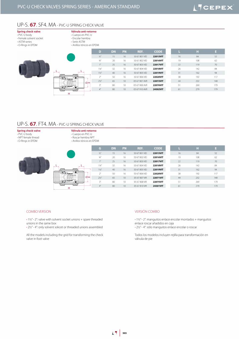
503
D DN PN REF. CODE½” 15 16 50 67 801 VID 22015VIT
¾” 20 16 50 67 802 VID 22016VIT
1” 25 16 50 67 803 VID 22017VIT
1¼” 32 16 50 67 804 VID 22018VIT
1½” 40 16 50 67 805 VID 22019VIT
2” 50 16 50 67 806 VID 22020VIT
2½” 65 10 05 67 907 AVR 22072VIT
3” 80 10 05 67 908 AVR 22076VIT
4” 80 10 05 67 910 AVR 24302VIT
L H E16 84 52
19 108 62
22 119 70
26 142 84
31 162 94
38 192 117
44 232 148
51 269 179
61 279 179
G DN PN REF. CODE½” 15 16 50 67 801 VID 22015VIT
¾” 20 16 50 67 802 VID 22016VIT
1” 25 16 50 67 803 VID 22017VIT
1¼” 32 16 50 67 804 VID 22018VIT
1½” 40 16 50 67 805 VID 22019VIT
2” 50 16 50 67 806 VID 22020VIT
2½” 65 10 05 67 807 VIR 22071VIT
3” 80 10 05 67 808 VIR 22075VIT
4” 80 10 05 67 810 VIR 24301VIT
L H E16 84 52
19 108 62
22 119 70
26 142 84
31 162 94
38 192 117
44 232 148
51 269 179
61 279 179
D
LL
E
H
G
LL
E
H
Válvula anti-retorno• Cuerpo en PVC-U• Encolar hembra• Serie ASTM• Anillos tóricos en EPDM
Spring check valve• PVC-U body• Female solvent socket• ASTM series• O-Rings in EPDM
UP-S. 67. SF4. MA - PVC-U SPRING CHECK VALVE
Válvula anti-retorno• Cuerpo en PVC-U• Roscar hembra NPT• Anillos tóricos en EPDM
Spring check valve• PVC-U body• NPT female thread• O-Rings in EPDM
UP-S. 67. FT4. MA - PVC-U SPRING CHECK VALVE
VERSIÓN COMBO
• 1½” - 2”: manguitos enlace encolar montados + manguitos enlace roscar añadidos en caja• 2½” - 4”: sólo manguitos enlace encolar o roscar
Todos los modelos incluyen rejilla para transformación en válvula de pie
COMBO VERSION
• 1½” - 2”: valve with solvent socket unions + spare threaded unions in the same box• 2½” - 4”: only solvent sokcet or threaded unions assembled
All the models including the grid for transforming the check valve in foot valve
PVC-U CHECK VALVES SPRING SERIES - AMERICAN STANDARD

504
PVC-U FOOT ValVes - sPrinG series VálVulas de Pie PVC-u - serie Muelle
PVC-U FOOT CHECK VALVES SPRING SERIES - AMERICAN STANDARD
Sizes Solvent cement D16 - D110 (DN10 - DN100)Threaded ⅜” - 4”
Standards Solvent socket - Metric, British standard, ASTM, JISThreaded - BSP, NPT
EN ISO 1452, EN ISO 15493, BS 4346-1, ASTM D 2467, JIS K 6743ISO 228-1, ASTM D 2464
Working pressure @ 20ºC (73ºF)
D16-D63 (⅜” - 2”): PN 16 (240 psi)D75 - D110 (2”1/2 - 4”): PN 10 (150 psi)
Minimum working pressure
Materials O-rings: EPDM / FPM
Characteristics • May be used either vertically and horizontally.• 100% factory tested.• Easy installation and maintenance.• Available in PVC-U.• Resistance to many inorganic chemicals.• Excellent flow characteristics.
• Se pueden usar indistintamente verticalmente o horizontalmente.• Probadas al 100% en fábrica.• Fácil instalación y mantenimiento.• Disponibles en PVC-U.• Resistencia a múltiples substancias químicas inorgánicas.• Excelentes características de conducción.
Certifications / regulations Check valve design regulation - ISO 16137:2006

505
FIG. Parts Despiece Material
1 Body Cuerpo PVC-U / PVC-C
2 Cone Cono de cierre PVC-U / PVC-C
3 Spring Muelle Staniless Steel AISI 302
4 Union nut Tuerca PVC-U / PVC-C
5 End connector Manguito enlace PVC-U / PVC-C
6 Cone o-ring Junta cono EPDM / FPM
7 End connector o-ring Junta manguito EPDM / FPM
8 Seal-carrier Portajuntas PVC-U / PVC-C
9 Foot valve screen Rejilla PP
1
2
4
8
5
7
3
6
9
4
20 years / water flow20 années / fluide de l�eau20 años / fluido de agua20 anos / caudal de água
18
16
14
12
10
8
6
4
2
0
0 10 20 30 40 50 60
Temperature / Température / Temperatura / Temperatura
Pres
sure
/Pre
ssio
n/ P
resió
n/ P
ress
ão
°C32 50 68 86 104 122 140 °F
barpsi270
240
210
180
150
120
90
60
30
0
DN
15
-3/8
”-½
”
DN
20
-¾
”DN
25
-1”
DN
32
-1¼
”
DN
40
-1½
”DN
50
-2”
DN
65
-2½
”
0,1
10 (l/min)
bar
Kv (l/min , p = 1 bar)
0,01
0,001
1
100 1.000 10.000
DN
80
-3”
DN
100
-4”
2,64 (GPM)26,42 264 2.642
1,50
0,15
0,01
15,0
psi
Flow / Débit / Caudal / Caudal
Pres
sure
loss
/Per
tede
char
ge/
Pérd
ida
deca
rga
/Per
dasd
eca
rga
PN 10
PN 16
PressUre / TeMPeraTUre GraPHdiaGraMa PresiÓN / TeMPeraTura
Pres
sure
/ Pr
esió
n
Temperature / Temperatura
Vida útil: 25 añosPresión hidrostática máxima que un com-ponente es capaz de soportar en servicio continuo (sin sobrepresión)
Life: 25 yearsHydrostatic maximum pressure a comp-nent may outstand in continous service (without overpressure)
PVC-U FOOT CHECK VALVES SPRING SERIES - AMERICAN STANDARD

506
D P (bar) Minimum opening
P (bar) Maximum opening
P (PSI) Minimum opening
P (PSI) Maximum opening
20 0,11 0,19 1,57 2,71
25 0,035 0,067 0,5 0,95
32 0,042 0,077 0,6 1,1
40 0,038 0,069 0,54 0,98
50 0,063 0,088 0,9 1,25
63 0,038 0,060 0,54 0,85
75 0,031 0,060 0,44 0,85
90 0,025 0,060 0,35 0,85
OPeninG PressUrePresiÓN de aPerTura
Minimum pressure: opening startMaximum pressure: open valve
Minimum pressure: opening startMaximum pressure: open valve
PressUre lOss DiaGraM
diaGraMa de PÉrdidas de CarGa
D16 - ⅜“ D20 - ½” D25 - ¾” D32 - 1” D40 - 1¼” D50 - 1½” D63 - 2” D75 - 2½” D90 - 3” D110 - 4”
A B A B A B A B A B A B A B A B A B A B
0,42 0,34 0,44 0,34 0,54 0,17 0,35 0,13 3,15 0,13 25,85 0,38 39,80 0,70 50,00 0,40 83,50 0,45 77,2 0,46
0,85 0,52 0,92 0,58 1,06 0,22 1,13 0,18 5,20 0,12 20,70 0,27 34,50 0,48 44,20 0,29 74,80 0,39 67,5 0,36
1,35 0,58 1,60 0,19 1,65 0,15 1,62 0,15 7,35 0,16 17,50 0,19 27,50 0,28 36,50 0,23 64,90 0,31 60,1 0,30
2,08 0,28 2,05 0,18 2,18 0,18 2,02 0,14 9,38 0,21 12,30 0,11 21,15 0,17 30,90 0,20 50,38 0,21 49,6 0,22
2,44 0,34 2,48 0,22 3,21 0,29 2,59 0,14 12,17 0,31 8,86 0,09 12,65 0,09 25,50 0,15 43,08 0,18 41,1 0,18
2,80 0,60 3,10 0,30 3,91 0,38 3,07 0,15 15,05 0,43 3,22 0,09 6,25 0,08 20,35 0,12 35,22 0,14 31,5 0,14
- - 3,53 0,35 4,32 0,44 3,51 0,16 - - - - - - 12,30 0,11 28,75 0,11 24,6 0,13
- - - - - - 4,20 0,20 - - - - - - 6,27 0,11 18,02 0,08 15,8 0,01
- - - - - - - - - - - - - - - - 8,28 0,11 7,9 0,08
- - - - - - - - - - - - - - - - - - - -
A = Flow (m3/h) Caudal (m3/h)
B = Pressure loss (bar) Pérdida de carga (bar)
PVC-U FOOT CHECK VALVES SPRING SERIES - AMERICAN STANDARD

507
D DN PN REF. CODE⅜” 15 16 05 66 900 MA 07423
½” 15 16 05 66 901 MA 06982
¾” 20 16 05 66 902 MA 06983
1” 25 16 05 66 903 MA 06984
1¼” 32 16 05 66 904 MA 06985
1½” 40 16 05 66 905 MA 06986
2” 50 16 05 66 906 MA 06987
2½” 65 10 05 66 907 MA 06988
3” 80 10 05 66 908 MA 06989
4” 80 10 05 66 910 MA 07425
L H E14 107 52
16 107 52
19 130 62
22 154 70
26 176 84
31 202 94
38 239 117
44 306 148
51 362 179
61 367 179
G DN PN REF. CODE.⅜” 15 16 05 66 800 07424
½” 15 16 05 66 801 06990
¾” 20 16 05 66 802 06991
1” 25 16 05 66 803 06992
1¼” 32 16 05 66 804 06993
1½” 40 16 05 66 805 06994
2” 50 16 05 66 806 06995
2½” 65 10 05 66 807 06996
3” 80 10 05 66 808 06997
4” 80 10 05 66 810 07426
L H E14 107 52
16 107 52
19 130 62
22 154 70
26 176 84
31 202 94
38 239 117
44 306 148
51 362 179
61 367 179
D E
L
HG E
L
H
Válvula de pie• Cuerpo en PVC-U• Encolar hembra• Serie ASTM• Anillos tóricos en EPDM
Foot valve• PVC-U body• Female solvent socket• ASTM series• O-Rings in EPDM
UP-S. 66. SF1. MA - PVC-U FOOT SPRING CHECK VALVE
Válvula de pie• Cuerpo en PVC-U• Roscar hembra NPT• Anillos tóricos en EPDM
Foot valve• PVC-U body• NPT female thread• O-Rings in EPDM
UP-S. 66. FT1. MA - PVC-U FOOT SPRING CHECK VALVE
Disponible con juntas en FPM
Available with FPM o-rings
PVC-U FOOT CHECK VALVES SPRING SERIES - AMERICAN STANDARD

508
PVC-U CHeCk ValVes - Ball series VálVulas aNTi-reTorNo PVC-u - serie bola
PVC-U CHECK VALVES BALL SERIES - AMERICAN STANDARD
Sizes Solvent cement D20 - D110 (DN15 - DN100)Threaded ½” - 4”
Standards Solvent socket - Metric, British standard, ASTM, JISThreaded - BSP, NPT
EN ISO 1452, EN ISO 15493, BS 4346-1, ASTM D 2467, JIS K 6743ISO 228-1, ASTM D 2464
Working pressure @ 20ºC (73ºF)
D20-D63 (½” - 2”): PN 16 (240 psi)D75 - D110 (2½” - 4”): PN 10 (150 psi)
Minimum return pressure 0,2 bar (3 psi)Minimal downstream pressure to keep the valve closed in horizontal position.Presión mínima aguas abajo para mantener la válvula cerrada en caso de instalación horizontal.
Materials O-rings: EPDM / FPM
Characteristics • Completely made in plastic - corrosion free.• 100% factory tested.• Excellent flow rate.• Easy installation and maintenance.• May be used either vertically and horizontally.• Available in PVC-U and Corzan® PVC-C.• Resistance to many inorganic chemicals.• Excellent flow characteristics.
• Fabricada completamente en plástico - libre de corrosión.• Probadas al 100% en fábrica.• Excelente coeficiente de caudal.• Fácil instalación y mantenimiento.• Se pueden usar indistintamente verticalmente o horizontalmente.• Disponibles en PVC-U y Corzan® PVC-C.• Resistencia a múltiples substancias químicas inorgánicas.• Excelentes características de conducción.
Certifications / regulations Check valve design regulation - ISO 16137:2006

509
FIG. Parts Despiece Material
1 Body Cuerpo PVC-U
3 Ball Bola PVC-U
4 Union nut Tuerca PVC-U
5 End connector Manguito enlace PVC-U
6 Closing ring Anillo de cierre PVC-U
7 Body o-ring Junta cuerpo EPDM / FPM
8 End connector o-ring Junta manguito EPDM / FPM
9 Seal-carrier Portajuntas PVC-U
14
7
9
58
3
6
4
5
20 years / water flow20 années / fluide de l�eau20 años / fluido de agua20 anos / caudal de água
18
16
14
12
10
8
6
4
2
0
0 10 20 30 40 50 60
Temperature / Température / Temperatura / Temperatura
Pres
sure
/Pre
ssio
n/ P
resió
n/ P
ress
ão
°C32 50 68 86 104 122 140 °F
barpsi270
240
210
180
150
120
90
60
30
0
DN
15
-3/8
”-½
”
DN
20
-¾
”DN
25
-1”
DN
32
-1¼
”
DN
40
-1½
”DN
50
-2”
DN
65
-2½
”
0,1
10 (l/min)
bar
Kv (l/min , p = 1 bar)
0,01
0,001
1
100 1.000 10.000
DN
80
-3”
DN
100
-4”
2,64 (GPM)26,42 264 2.642
1,50
0,15
0,01
15,0
psi
Flow / Débit / Caudal / Caudal
Pres
sure
loss
/Per
tede
char
ge/
Pérd
ida
deca
rga
/Per
dasd
eca
rga
PN 10
PN 16
PressUre / TeMPeraTUre GraPHdiaGraMa PresiÓN / TeMPeraTura
Pres
sure
/ Pr
esió
n
Temperature / Temperatura
Vida útil: 25 añosPresión hidrostática máxima que un com-ponente es capaz de soportar en servicio continuo (sin sobrepresión)
Life: 25 yearsHydrostatic maximum pressure a comp-nent may outstand in continous service (without overpressure)
PVC-U CHECK VALVES BALL SERIES - AMERICAN STANDARD
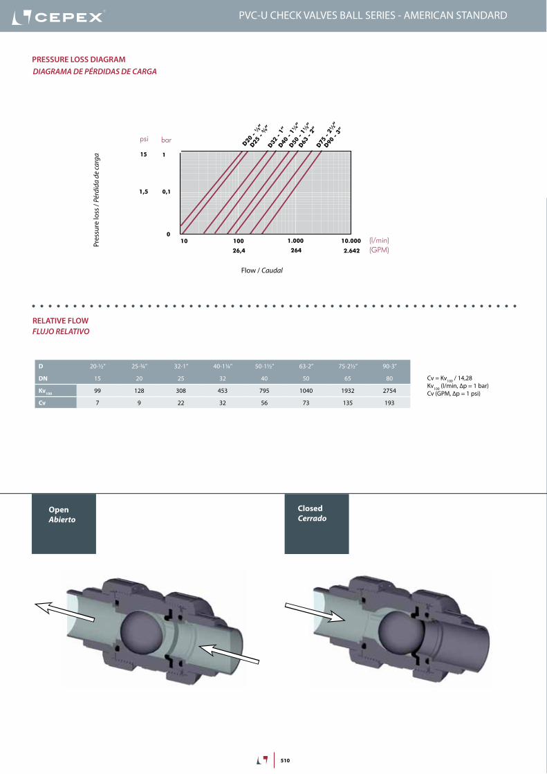
510
PVC-U CHECK VALVES BALL SERIES - AMERICAN STANDARD
OpenAbierto
ClosedCerrado
Temperature / Température / Temperatura / Temperatura
20 years / water flow20 années / fluide de l�eau20 años / fluido de agua20 anos / caudal de água
Pres
sure
/Pre
ssio
n/ P
resió
n/ P
ress
ão
18
16
14
12
10
8
6
4
2
0
0 10 20 30 40 50 60 70 80 90 °C32 50 68 86 104 122 140 158 176 194 °F
barpsi
PVC -U
PVC -C
270
240
210
180
150
120
90
60
30
0
PN 16 (240 psi)
PN 10 (150 psi)
Pres
sure
loss
/ Per
tede
char
ge/
Pérd
ida
deca
rga
/ Per
das d
eca
rga
Flow / Débit / Caudal / Caudal
100 1.000 10.000
1
mca
(l/min)
10
26,4 264 2.642 (GPM)
1,5
psi
15
10D20
-½
”
D25
-¾
”D32
-1”
D40
-1¼
”
D50
-1½
”
D63
-2”
D75
-2½
”
D90
-3”
0
relaTiVe FlOWFluJo relaTiVo
D 20-½” 25-¾” 32-1” 40-1¼” 50-1½” 63-2” 75-2½” 90-3”
DN 15 20 25 32 40 50 65 80
Kv100 99 128 308 453 795 1040 1932 2754
Cv 7 9 22 32 56 73 135 193
PressUre lOss DiaGraMdiaGraMa de PÉrdidas de CarGa
Pres
sure
loss
/ Pé
rdid
a de
carg
a
Flow / Caudal
Cv = Kv100 / 14,28Kv100 (l/min, ∆p = 1 bar)Cv (GPM, ∆p = 1 psi)
bar
1
0,1

511
insTrUCCiOnes De MOnTaje
Uniones encoladas o roscadasAfloje las tuercas (4) de la válvula y sepárelas de los manguitos (5). Introduzca las tuercas en los tubos y a continuación fije los manguitos en los extremos del tubo. Las uniones encoladas se realizarán con un adhesivo para tubos de PVC-U o PVC-C rígido y no se aplicará presión hasta transcurridas al menos 1 hora por bar. En las uniones roscadas se colocará cinta de PTFE en las roscas macho. A continuación ya podrá colocarse la válvula entre los manguitos y apretar a mano las tuercas sobre la válvula.
asseMBly insTrUCTiOns
Solvent socket or threaded unionsLoosen the valve union nuts (4) and separate these and the end connectors (5) from the valve body. Pass the pipe through the nuts and then place the bushes over the end of the pipe. The socket unions should be guied onto the pipe using a PVC-U or PVC-C adhesive and pressure should not be applied to the system until a drying period of at least 1 hour per bar of working pressure has elapsed. In the case of threaded unions, PTFE tape should be applied to the male threads. The pipes can now be attached to the valve by hand tightening down the nuts.
1
2
3
4
5
PVC-U CHECK VALVES BALL SERIES - AMERICAN STANDARD

512
D DN PN REF. CODE½” 15 16 05 67 801 ED 27360
¾” 20 16 05 67 802 ED 27361
1” 25 16 05 67 803 ED 27362
1¼” 32 16 05 67 804 ED 27363
1½” 40 16 05 67 805 ED 27000
2” 50 16 05 67 806 ED 27001
2½” 65 10 05 67 907 EMA 27374
3” 80 10 05 67 908 EMA 27375
4” 80 10 05 67 910 EMA 27376
L H E16 84 52
19 108 62
22 119 70
26 142 84
31 162 94
38 192 117
44 232 148
51 269 179
51 269 179
G DN PN REF. CODE½” 15 16 05 67 801 ED 27360
¾” 20 16 05 67 802 ED 27361
1” 25 16 05 67 803 ED 27362
1¼” 32 16 05 67 804 ED 27363
1½” 40 16 05 67 805 ED 27000
2” 50 16 05 67 806 ED 27001
2½” 65 10 05 67 807 E 27368
3” 80 10 05 67 808 E 27369
4” 80 10 05 67 810 E 27370
L H E16 84 52
19 108 62
22 119 70
26 142 84
31 167 94
38 192 117
44 232 148
51 269 179
61 279 179
D
LL
EH
G
LL
E
H
Válvula anti-retorno de bola• Cuerpo en PVC-U• Encolar hembra• Serie ASTM• Anillos tóricos en EPDM
Ball check valve• PVC-U body• Female solvent socket• ASTM series• O-rings in EPDM
UP-B. 67. SF1. MA - PVC-U BALL CHECK VALVE
Válvula anti-retorno de bola• Cuerpo en PVC-U• Roscar hembra NPT• Anillos tóricos en EPDM
Ball check valve• PVC-U body• NPT female thread• O-Rings in EPDM
UP-B. 67. FT1. MA - PVC-U BALL CHECK VALVE
VERSIÓN COMBO
• 1½” - 2”: manguitos enlace encolar montados + manguitos enlace roscar añadidos en caja• 2½” - 4”: sólo manguitos enlace encolar o roscar
Todos los modelos incluyen rejilla para transformación en válvula de pie
PVC-U CHECK VALVES BALL SERIES - AMERICAN STANDARD
COMBO VERSION
• 1½” - 2”: valve with solvent socket unions + spare threaded unions in the same box• 2½” - 4”: only solvent sokcet or threaded unions assembled
All the models including the grid for transforming the check valve in foot valve

513
G DN PN REF. CODE½” 15 16 05 67 801 VED 27364
¾” 20 16 05 67 802 VED 27365
1” 25 16 05 67 803 VED 27366
1¼” 32 16 05 67 804 VED 27367
1½” 40 16 05 67 805 VED 27002
2” 50 16 05 67 806 VED 27003
2½” 65 10 05 67 807 VE 27371
3” 80 10 05 67 808 VE 27372
4” 80 10 05 67 810 VE 27373
L H E16 84 52
19 108 62
22 119 70
26 142 84
31 167 94
38 192 117
44 232 148
51 269 179
61 279 179
G
LL
E
H
Válvula anti-retorno de bola• Cuerpo en PVC-U• Roscar hembra NPT• Anillos tóricos en FPM
Ball check valve• PVC-U body• NPT female thread• O-Rings in FPM
UP-B. 67. FT4. MA - PVC-U BALL CHECK VALVE
D DN PN REF. CODE½” 15 16 05 67 801 VED 27364
¾” 20 16 05 67 802 VED 27365
1” 25 16 05 67 803 VED 27366
1¼” 32 16 05 67 804 VED 27367
1½” 40 16 05 67 805 VED 27002
2” 50 16 05 67 806 VED 27003
2½” 65 10 05 67 907 VEMA 27377
3” 80 10 05 67 908 VEMA 27378
4” 80 10 05 67 910 VEMA 27379
L H E16 84 52
19 108 62
22 119 70
26 142 84
31 162 94
38 192 117
44 232 148
51 269 179
51 269 179D
LL
EH
Válvula anti-retorno de bola• Cuerpo en PVC-U• Encolar hembra• Serie ASTM• Anillos tóricos en FPM
Ball check valve• PVC-U body• Female solvent socket• ASTM series• O-Rings in FPM
UP-B. 67. SF4. MA - PVC-U BALL CHECK VALVE
VERSIÓN COMBO
• 1½” - 2”: manguitos enlace encolar montados + manguitos enlace roscar añadidos en caja• 2½” - 4”: sólo manguitos enlace encolar o roscar
Todos los modelos incluyen rejilla para transformación en válvula de pie
PVC-U CHECK VALVES BALL SERIES - AMERICAN STANDARD
COMBO VERSION
• 1½” - 2”: valve with solvent socket unions + spare threaded unions in the same box• 2½” - 4”: only solvent sokcet or threaded unions assembled
All the models including the grid for transforming the check valve in foot valve

514
PVC-U FOOT ValVes - Ball series VálVulas de Pie PVC-u - serie bola
PVC-U FOOT CHECK VALVES BALL SERIES - AMERICAN STANDARD
Sizes Solvent cement D20 - D110 (DN15 - DN100)Threaded ½” - 4”
Standards Solvent socket - Metric, British standard, ASTM, JISThreaded - BSP, NPT
EN ISO 1452, EN ISO 15493, BS 4346-1, ASTM D 2467, JIS K 6743ISO 228-1, ASTM D 2464
Working pressure @ 20ºC (73ºF)
D20-D63 (⅜” - 2”): PN 16 (240 psi)D75 - D110 (2½” - 4”): PN 10 (150 psi)
Minimum return pressure 0,2 bar (3 psi)Minimal downstream pressure to keep the valve closed in horizontal position.Presión mínima aguas abajo para mantener la válvula cerrada en caso de instalación horizontal.
Materials O-rings: EPDM / FPM
Characteristics • Completely made in plastic - corrosion free.• 100% factory tested.• Easy installation and maintenance.• May be used either vertically and horizontally.• Available in PVC-U.• Resistance to many inorganic chemicals.• Excellent flow characteristics.
• Fabricada completamente en plástico - libre de corrosión• Probadas al 100% en fábrica.• Fácil instalación y mantenimiento.• Se pueden usar indistintamente verticalmente o horizontalmente.• Disponibles en PVC-U.• Resistencia a múltiples substancias químicas inorgánicas.• Excelentes características de conducción.
Certifications / regulations Check valve design regulation - ISO 16137:2006
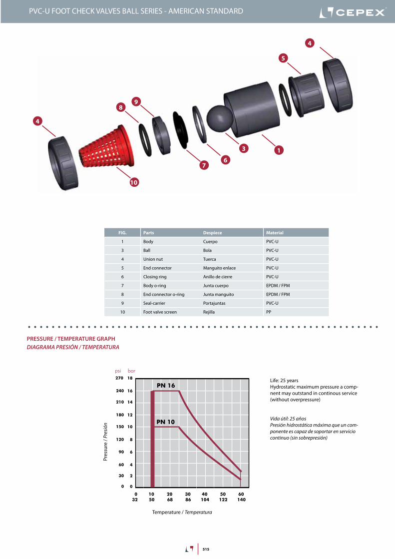
515
FIG. Parts Despiece Material
1 Body Cuerpo PVC-U
3 Ball Bola PVC-U
4 Union nut Tuerca PVC-U
5 End connector Manguito enlace PVC-U
6 Closing ring Anillo de cierre PVC-U
7 Body o-ring Junta cuerpo EPDM / FPM
8 End connector o-ring Junta manguito EPDM / FPM
9 Seal-carrier Portajuntas PVC-U
10 Foot valve screen Rejilla PP
1
4
7
98
3
6
10
4
5
PVC-U FOOT CHECK VALVES BALL SERIES - AMERICAN STANDARD
20 years / water flow20 années / fluide de l�eau20 años / fluido de agua20 anos / caudal de água
18
16
14
12
10
8
6
4
2
0
0 10 20 30 40 50 60
Temperature / Température / Temperatura / Temperatura
Pres
sure
/Pre
ssio
n/ P
resió
n/ P
ress
ão
°C32 50 68 86 104 122 140 °F
barpsi270
240
210
180
150
120
90
60
30
0
DN
15
-3/8
”-½
”
DN
20
-¾
”DN
25
-1”
DN
32
-1¼
”
DN
40
-1½
”DN
50
-2”
DN
65
-2½
”
0,1
10 (l/min)
bar
Kv (l/min , p = 1 bar)
0,01
0,001
1
100 1.000 10.000
DN
80
-3”
DN
100
-4”
2,64 (GPM)26,42 264 2.642
1,50
0,15
0,01
15,0
psi
Flow / Débit / Caudal / Caudal
Pres
sure
loss
/Per
tede
char
ge/
Pérd
ida
deca
rga
/Per
dasd
eca
rga
PN 10
PN 16
PressUre / TeMPeraTUre GraPHdiaGraMa PresiÓN / TeMPeraTura
Pres
sure
/ Pr
esió
n
Temperature / Temperatura
Vida útil: 25 añosPresión hidrostática máxima que un com-ponente es capaz de soportar en servicio continuo (sin sobrepresión)
Life: 25 yearsHydrostatic maximum pressure a comp-nent may outstand in continous service (without overpressure)

516
PressUre lOss DiaGraMdiaGraMa de PÉrdidas de CarGa
D20 - ½” D25 - ¾” D32 - 1” D40 - 1¼” D50 - 1½” D63 - 2” D75 - 2½” D90 - 3”
A B A B A B A B A B A B A B A B
1,65 0,13 1,47 0,05 4,36 0,08 4,87 0,15 6,41 0,002 12,53 0,05 12,32 0,05 7,13 0,009
2,33 0,24 2,01 0,054 4,89 0,11 6,21 0,17 11,3 0,02 14,9 0,07 14,95 0,06 15,91 0,04
3,34 0,44 2,34 0,09 5,44 0,15 7,52 0,21 18,76 0,16 17,12 0,11 19,53 0,11 28,58 0,13
3,85 0,52 2,95 0,18 5,89 0,21 10,61 0,27 25,05 0,34 21,7 0,16 25 0,17 37,22 0,22
4,52 0,69 3,6 0,29 7,01 0,26 12,53 0,34 28,44 0,41 27,36 0,28 32,6 0,28 45,61 0,53
- - 4,03 0,36 9,23 0,39 15,23 0,4 - - 32,02 0,37 41,43 0,55 58,5 0,64
- - 4,21 0,38 - - - - - - 37,68 0,43 - - - -
A = Flow (m3/h) Caudal (m3/h)
B = Pressure loss (bar) Pérdida de carga (bar)
PVC-U FOOT CHECK VALVES BALL SERIES - AMERICAN STANDARD

517
D DN PN REF. CODE½” 15 16 05 67 801 ED 27360
¾” 20 16 05 67 802 ED 27361
1” 25 16 05 67 803 ED 27362
1¼” 32 16 05 67 804 ED 27363
1½” 40 16 05 67 805 ED 27000
2” 50 16 05 67 806 ED 27001
2½” 65 10 05 67 907 EMA 27374
3” 80 10 05 67 908 EMA 27375
4” 80 10 05 67 910 EMA 27376
L H E16 84 52
19 108 62
22 119 70
26 142 84
31 162 94
38 192 117
44 232 148
51 269 179
51 269 179
G DN PN REF. CODE½” 15 16 05 67 801 ED 27360
¾” 20 16 05 67 802 ED 27361
1” 25 16 05 67 803 ED 27362
1¼” 32 16 05 67 804 ED 27363
1½” 40 16 05 67 805 ED 27000
2” 50 16 05 67 806 ED 27001
2½” 65 10 05 67 807 E 27368
3” 80 10 05 67 808 E 27369
4” 80 10 05 67 810 E 27370
L H E16 84 52
19 108 62
22 119 70
26 142 84
31 167 94
38 192 117
44 232 148
51 269 179
61 279 179
D
LL
EH
G
LL
E
H
Válvula anti-retorno de bola• Cuerpo en PVC-U• Encolar hembra• Serie ASTM• Anillos tóricos en EPDM
Ball check valve• PVC-U body• Female solvent socket• ASTM series• O-rings in EPDM
UP-B. 67. SF1. MA - PVC-U BALL FOOT CHECK VALVE
Válvula anti-retorno de bola• Cuerpo en PVC-U• Roscar hembra NPT• Anillos tóricos en EPDM
Ball check valve• PVC-U body• NPT female thread• O-Rings in EPDM
UP-B. 67. FT1. MA - PVC-U BALL FOOT CHECK VALVE
VERSIÓN COMBO
• 1½” - 2”: manguitos enlace encolar montados + manguitos enlace roscar añadidos en caja• 2½” - 4”: sólo manguitos enlace encolar o roscar
Todos los modelos incluyen rejilla para transformación en válvula de pie
PVC-U FOOT CHECK VALVES BALL SERIES - AMERICAN STANDARD
COMBO VERSION
• 1½” - 2”: valve with solvent socket unions + spare threaded unions in the same box• 2½” - 4”: only solvent sokcet or threaded unions assembled
All the models including the grid for transforming the check valve in foot valve

518
D DN PN REF. CODE½” 15 16 05 67 801 VED 27364
¾” 20 16 05 67 802 VED 27365
1” 25 16 05 67 803 VED 27366
1¼” 32 16 05 67 804 VED 27367
1½” 40 16 05 67 805 VED 27002
2” 50 16 05 67 806 VED 27003
2½” 65 10 05 67 907 VEMA 27377
3” 80 10 05 67 908 VEMA 27378
4” 80 10 05 67 910 VEMA 27379
L H E16 84 52
19 108 62
22 119 70
26 142 84
31 162 94
38 192 117
44 232 148
51 269 179
51 269 179
G DN PN REF. CODE½” 15 16 05 67 801 VED 27364
¾” 20 16 05 67 802 VED 27365
1” 25 16 05 67 803 VED 27366
1¼” 32 16 05 67 804 VED 27367
1½” 40 16 05 67 805 VED 27002
2” 50 16 05 67 806 VED 27003
2½” 65 10 05 67 807 VE 27371
3” 80 10 05 67 808 VE 27372
4” 80 10 05 67 810 VE 27373
L H E16 84 52
19 108 62
22 119 70
26 142 84
31 167 94
38 192 117
44 232 148
51 269 179
61 279 179
D
LL
EH
G
LL
E
H
Válvula anti-retorno de bola• Cuerpo en PVC-U• Encolar hembra• Serie ASTM• Anillos tóricos en FPM
Ball check valve• PVC-U body• Female solvent socket• ASTM series• O-Rings in FPM
UP-B. 67. SF4. MA - PVC-U BALL FOOT CHECK VALVE
Válvula anti-retorno de bola• Cuerpo en PVC-U• Roscar hembra NPT• Anillos tóricos en FPM
Ball check valve• PVC-U body• NPT female thread• O-Rings in FPM
UP-B. 67. FT4. MA - PVC-U BALL FOOT CHECK VALVE
VERSIÓN COMBO
• 1½” - 2”: manguitos enlace encolar montados + manguitos enlace roscar añadidos en caja• 2½” - 4”: sólo manguitos enlace encolar o roscar
Todos los modelos incluyen rejilla para transformación en válvula de pie
PVC-U FOOT CHECK VALVES BALL SERIES - AMERICAN STANDARD
COMBO VERSION
• 1½” - 2”: valve with solvent socket unions + spare threaded unions in the same box• 2½” - 4”: only solvent sokcet or threaded unions assembled
All the models including the grid for transforming the check valve in foot valve

519
PVC-U sWinG CHeCk ValVes VálVulas de ClaPeTa PVC-u
PVC-U SWING CHECK VALVES - AMERICAN STANDARD
Sizes Metric flanges D63 - D315 (DN50 - DN300)ASTM flanges 4” - 12”
Standards ISO/DINASTM - 4” - 12”
EN 558-1ANSI B.16.5 cl. 150
Working pressure @ 20ºC (73ºF)
D63 - D315 (2” - 12”): PN 6 (90 psi)
Minimum return pressure 0,2 bar (3 psi)Minimal downstream pressure to keep the valve closed in horizontal position.Presión mínima aguas abajo para mantener la válvula cerrada en caso de instalación horizontal.
Materials O-rings: EPDM / FPM
Characteristics • Requires little space in piping systems.• Easy installation: wafer body slips between standard flanges. No gaskets required.• Vertical and horitzontal operation.• Excellent flow characteristics.
Do not install the valve at a distance lower than 5 x D of the pump out.Install with pipe DIN PN 10. In case of PN 16, the valve could be damaged.
• Requiere poco espacio en la instalación.• Fácil instalación: se monta entre bridas standard. Sin necesidad de juntas adicionales.• Instalación vertical y horizontal.• Excelentes características de conducción.
No montar la válvula a una distancia inferior a 5 x D de la salida de una bomba.Montar con tubo PN 10. En caso de usar un PN 16 se podrían ocasionar daños en la válvula.
Certifications / regulations Check valve design regulation - ISO 16137:2006

520
PVC-U SWING CHECK VALVES - AMERICAN STANDARD
FIG. Parts Despiece Material
1 Body Cuerpo PVC-U
2 Flap Clapeta PVC-U
3 Cap Tapón PP
4 Body O-ring Junta cuerpo EPDM / FPM
5 Flap O-ring Junta clapeta EPDM / FPM
1
2
4
5
3
4
20 years / water flow20 années / fluide de l�eau20 años / fluido de agua20 anos / caudal de água
18
16
14
12
10
8
6
4
2
0
0 10 20 30 40 50 60
Pres
sure
/ Pre
ssio
n/ P
resió
n/ P
ress
ão
°C32 50 68 86 104 122 140 °F
barpsi270
240
210
180
150
120
90
60
30
0
DN
65
-2½
”
DN
80
-3”
DN
100
-4”
DN
110
-4½
”
DN
125
-5”
DN
150
-6”
DN
175
-7”
DN
200
-8”
1
0.1
0.0110 100 1.000
Flow / Débit / Caudal / Caudal
15
1.5
0.15
barpsi
m3/hft3/min5,88 58,8 588
Temperature / Température / Temperatura / Temperatura
Pres
sure
loss
/Per
tede
char
ge/
Pérd
ida
deca
rga
/ Per
dade
carg
a
PN 6 (90 psi)
D50
-½
”
DN
250
-9”
DN
300
-12”
PressUre / TeMPeraTUre GraPHdiaGraMa PresiÓN / TeMPeraTura
Pres
sure
/ Pr
esió
n
Temperature / Temperatura
Vida útil: 25 añosPresión hidrostática máxima que un com-ponente es capaz de soportar en servicio continuo (sin sobrepresión)
Life: 25 yearsHydrostatic maximum pressure a comp-nent may outstand in continous service (without overpressure)

521
PVC-U SWING CHECK VALVES - AMERICAN STANDARD
20 years / water flow20 années / fluide de l�eau20 años / fluido de agua20 anos / caudal de água
18
16
14
12
10
8
6
4
2
0
0 10 20 30 40 50 60
Pres
sure
/ Pre
ssio
n/ P
resió
n/ P
ress
ão
°C32 50 68 86 104 122 140 °F
barpsi270
240
210
180
150
120
90
60
30
0
DN
65
-2½
”
DN
80
-3”
DN
100
-4”
DN
110
-4½
”
DN
125
-5”
DN
150
-6”
DN
175
-7”
DN
200
-8”
1
0.1
0.0110 100 1.000
Flow / Débit / Caudal / Caudal
15
1.5
0.15
barpsi
m3/hft3/min5,88 58,8 588
Temperature / Température / Temperatura / Temperatura
Pres
sure
loss
/Per
tede
char
ge/
Pérd
ida
deca
rga
/ Per
dade
carg
a
PN 6 (90 psi)
D50
-½
”
DN
250
-9”
DN
300
-12”
PressUre lOss DiaGraMdiaGraMa de PÉrdidas de CarGa
Pres
sure
loss
/ Pé
rdid
a de
carg
a
Flow / Caudal
relaTiVe FlOWFluJo relaTiVo
D 63 75 90 110 125 140 160 200 225 250 280 315
DN 50 65 80 100 125 125 150 175 200 250 250 300
Kv100 57 85 130 200 390 480 600 800 900 1.600 1.600 1.850
Cv 4,0 6,0 9,1 14,0 27,3 33,6 42,0 56,0 63,0 112,0 112,0 129,6
Cv = Kv100 / 14,28Kv100 (l/min, ∆p = 1 bar)Cv (GPM, ∆p = 1 psi)
D DN PN REF. CODE4” 100 6 05 65 110 08986
4½” 110 6 05 65 125 09040
5” 125 6 05 65 140 08987
6” 150 6 05 65 160 08988
7” 175 6 05 65 200 09041
8” 200 6 05 65 225 08989
9” 250 6 05 65 250 37056
10” 250 6 05 65 280 * 41865
12” 300 6 05 65 315 * 37057
A B C164 22 70
170 25 83
195 23 92
220 25 112
247 28 139
275 35 150
328 40 162
330 40 189
380 45 226AC
B
Válvula de clapeta• Cuerpo en PVC-U• Anillos tóricos en EPDM (FPM bajo pedido)
Swing check valve• PVC-U body• O-rings in EPDM (FPM upon request)
UP. 65 - SWING CHECK VALVE

577
PVC-C CHeCk ValVes - sPrinG series VálVulas aNTi-reTorNo PVC-C - serie Muelle
PVC-C CHECK VALVES SPRING SERIES - METRIC STANDARD
Sizes Solvent cement D16 - D110 (DN10 - DN100)Threaded ⅜” - 4”
Standards Solvent socket - Metric, British standard, ASTM, JISThreaded - BSP, NPT
EN ISO 1452, EN ISO 15493, BS 4346-1, ASTM D 2467, JIS K 6743ISO 228-1, ASTM D 2464
Working pressure @ 20ºC (73ºF)
D16-D63 (⅜” - 2”): PN 16 (240 psi)D75 - D110 (2”1/2 - 4”): PN 10 (150 psi)
Minimum working pressure
Materials O-rings: EPDM / FPM
Characteristics • May be used either vertically and horizontally.• 100% factory tested.• Easy installation and maintenance.• Available in PVC-U and Corzan® PVC-C.• Resistance to many inorganic chemicals.• Excellent flow characteristics.
• Se pueden usar indistintamente verticalmente o horizontalmente.• Probadas al 100% en fábrica.• Fácil instalación y mantenimiento.• Disponibles en PVC-U y Corzan® PVC-C.• Resistencia a múltiples substancias químicas inorgánicas.• Excelentes características de conducción.
Certifications / regulations Check valve design regulation - ISO 16137:2006

578
FIG. Parts Despiece Material
1 Body Cuerpo PVC-C
2 Cone Cono de cierre PVC-C
3 Spring Muelle Stainless Steel AISI 302 / PTFE coated *
4 Union nut Tuerca PVC-C
5 End connector Manguito enlace PVC-C
6 Cone o-ring Junta cono EPDM / FPM
7 End connector o-ring Junta manguito EPDM / FPM
8 Seal-carrier Portajuntas PVC-C
1
2
4
8
57
3
6
4
5
PressUre / TeMPeraTUre GraPHdiaGraMa PresiÓN / TeMPeraTura
PN 16
PN 10
Pres
sure
/ Pr
esió
n
Temperature / Temperatura
Vida útil: 25 añosPresión hidrostática máxima que un com-ponente es capaz de soportar en servicio continuo (sin sobrepresión)
Life: 25 yearsHydrostatic maximum pressure a comp-nent may outstand in continous service (without overpressure)
PVC-C CHECK VALVES SPRING SERIES - METRIC STANDARD

579
PVC-C CHECK VALVES SPRING SERIES - METRIC STANDARD
Pres
sure
loss
/ Per
tede
char
ge/
Pérd
ida
deca
rga
/ Per
das d
eca
rga
Flow / Débit / Caudal / Caudal
100 1.000 10.000
1
mca
(l/min)
10
26,4 264 2.642 (GPM)
1,5
psi
15
10
Temperature / Température / Temperatura / Temperatura
20 years / water flow20 années / fluide de l�eau20 años / fluido de agua20 anos / caudal de água
Pres
sure
/Pre
ssio
n/ P
resió
n/ P
ress
ão
18
16
14
12
10
8
6
4
2
0
0 10 20 30 40 50 60 70 80 90 °C32 50 68 86 104 122 140 158 176 194 °F
barpsi
PVC -U
PVC-C
270
240
210
180
150
120
90
60
30
0
PN 16 (240 psi)
PN 10 (150 psi)
D20
-½
”D25
-¾
”D32
-1”
D40
-1¼
”D50
-1½
”
D63
-2”
D75
-2½
”
D90
-3”
D110
-4”
D16
-3/8
”
0
D 20-½” 25-¾” 32-1” 40-1¼” 50-1½” 63-2” 75-2½”
DN 15 20 25 32 40 50 65
Kv100 68 133 208 383 667 850 1533
Cv 5 9 15 27 47 60 107
OpenAbierto
ClosedCerrado
D P (bar) Minimum opening
P (bar) Maximum opening
P (psi) Minimum opening
P (psi) Maximum opening
20 0,11 0,19 1,57 2,71
25 0,035 0,067 0,5 0,95
32 0,042 0,077 0,6 1,1
40 0,038 0,069 0,54 0,98
50 0,063 0,088 0,9 1,25
63 0,038 0,060 0,54 0,85
75 0,031 0,060 0,44 0,85
90 0,025 0,060 0,35 0,85
OPeninG PressUrePresiÓN de aPerTura
Minimum pressure: opening startMaximum pressure: open valve
Minimum pressure: opening startMaximum pressure: open valve
PressUre lOss DiaGraMdiaGraMa de PÉrdidas de CarGa
relaTiVe FlOWFluJo relaTiVo
Cv = Kv100 / 14,28Kv100 (l/min, ∆p = 1 bar)Cv (GPM, ∆p = 1 psi)
Pres
sure
loss
/ Pé
rdid
a de
carg
a
Flow / Caudal

580
insTrUCCiOnes De MOnTaje
Uniones encoladas o roscadasAfloje las tuercas (4) de la válvula y sepárelas de los manguitos (5). Introduzca las tuercas en los tubos y a continuación fije los manguitos en los extremos del tubo. Las uniones encoladas se realizarán con un adhesivo para tubos de PVC-U o PVC-C rígido y no se aplicará presión hasta transcurridas al menos 1 hora por bar. En las uniones roscadas se colocará cinta de PTFE en las roscas macho. A continuación ya podrá colocarse la válvula entre los manguitos y apretar a mano las tuercas sobre la válvula.
asseMBly insTrUCTiOns
Solvent socket or threaded unionsLoosen the valve union nuts (4) and separate these and the end connectors (5) from the valve body. Pass the pipe through the nuts and then place the bushes over the end of the pipe. The socket unions should be guied onto the pipe using a PVC-U or PVC-C adhesive and pressure should not be applied to the system until a drying period of at least 1 hour per bar of working pressure has elapsed. In the case of threaded unions, PTFE tape should be applied to the male threads. The pipes can now be attached to the valve by hand tightening down the nuts.
1
2
3
4
5
PVC-C CHECK VALVES SPRING SERIES - METRIC STANDARD

581
D DN PN REF. CODE16 10 16 35 67 016 22844
20 15 16 35 67 020 22845
25 20 16 35 67 025 22846
32 25 16 35 67 032 22847
40 32 16 35 67 040 22848
50 40 16 35 67 050 22849
63 50 16 35 67 063 22850
75 65 10 35 67 075 22851
90 80 10 35 67 090 22852
110 80 10 35 67 110 22853
L H E14 84 52
16 84 52
19 108 62
22 119 70
26 142 84
31 162 94
38 192 117
44 232 148
51 269 179
51 269 179
G DN PN REF. CODE⅜” 10 16 35 67 616 22854
½” 15 16 35 67 620 22855
¾” 20 16 35 67 625 22856
1” 25 16 35 67 632 22857
1¼” 32 16 35 67 640 22858
1½” 40 16 35 67 650 22859
2” 50 16 35 67 663 22860
2½” 65 10 35 67 675 22861
3” 80 10 35 67 690 22862
4” 80 10 35 67 710 22863
L H E14 84 52
16 84 52
19 108 62
22 119 70
26 142 84
31 162 94
38 192 117
44 232 148
51 269 179
51 269 179
D DN PN REF. CODE16 10 16 35 67 016 VI 22864
20 15 16 35 67 020 VI 22865
25 20 16 35 67 025 VI 22866
32 25 16 35 67 032 VI 22867
40 32 16 35 67 040 VI 22868
50 40 16 35 67 050 VI 22869
63 50 16 35 67 063 VI 22870
75 65 10 35 67 075 VI 22871
90 80 10 35 67 090 VI 22872
110 80 10 35 67 110 VI 22873
L H E14 84 52
16 84 52
19 108 62
22 119 70
26 142 84
31 162 94
38 192 117
44 232 148
51 269 179
51 269 179
G DN PN REF. CODE⅜” 10 16 35 67 616 VI 22874
½” 15 16 35 67 620 VI 22875
¾” 20 16 35 67 625 VI 22876
1” 25 16 35 67 632 VI 22877
1¼” 32 16 35 67 640 VI 22878
1½” 40 16 35 67 650 VI 22879
2” 50 16 35 67 663 VI 22880
2½” 65 10 35 67 675 VI 22881
3” 80 10 35 67 690 VI 22882
4” 80 10 35 67 710 VI 22883
L H E14 84 52
16 84 52
19 108 62
22 119 70
26 142 84
31 162 94
38 192 117
44 232 148
51 269 179
51 269 179
D
LL
E
HD
LL
E
H
G
LL
E
H
G
LL
E
H
Válvula anti-retorno• Cuerpo en Corzan® PVC-C• Encolar hembra• Serie métrica• Anillos tóricos en EPDM
Spring check valve• Corzan® PVC-C body• Female solvent socket• Metric series• O-Rings in EPDM
CP-S. 67. SF1 - PVC-C SPRING CHECK VALVE
Válvula anti-retorno• Cuerpo en Corzan® PVC-C• Roscar hembra BSP• Anillos tóricos en EPDM
Spring check valve• Corzan® PVC-C body• BSP female thread• O-Rings in EPDM
CP-S. 67. FT1 - PVC-C SPRING CHECK VALVE
Válvula anti-retorno• Cuerpo en Corzan® PVC-C• Encolar hembra• Serie métrica• Anillos tóricos en FPM
Spring check valve• Corzan® PVC-C body• Female solvent socket• Metric series• O-Rings in FPM
CP-S. 67. SF4 - PVC-C SPRING CHECK VALVE
Válvula anti-retorno• Cuerpo en Corzan® PVC-C• Roscar hembra BSP• Anillos tóricos en FPM
Spring check valve• Corzan® PVC-C body• BSP female thread• O-Rings in FPM
CP-S. 67. FT4 - PVC-C SPRING CHECK VALVE
PVC-C CHECK VALVES SPRING SERIES - METRIC STANDARD

582
PVC-C CHeCk ValVes - Ball series VálVulas aNTi-reTorNo PVC-C - serie bola
PVC-C CHECK VALVES BALL SERIES - METRIC STANDARD
Sizes Solvent cement D20 - D110 (DN15 - DN100)Threaded ½” - 4”
Standards Solvent socket - Metric, British standard, ASTM, JISThreaded - BSP, NPT
EN ISO 1452, EN ISO 15493, BS 4346-1, ASTM D 2467, JIS K 6743ISO 228-1, ASTM D 2464
Working pressure @ 20ºC (73ºF)
D20-D63 (½” - 2”): PN 16 (240 psi)D75 - D110 (2½” - 4”): PN 10 (150 psi)
Minimum return pressure 0,2 bar (3 psi)Minimal downstream pressure to keep the valve closed in horizontal position.Presión mínima aguas abajo para mantener la válvula cerrada en caso de instalación horizontal.
Materials O-rings: EPDM / FPM
Characteristics • Completely made in plastic - corrosion free.• 100% factory tested.• Excellent flow rate.• Easy installation and maintenance.• May be used either vertically and horizontally.• Available in PVC-U and Corzan® PVC-C.• Resistance to many inorganic chemicals.• Excellent flow characteristics.
• Fabricada completamente en plástico - libre de corrosión.• Probadas al 100% en fábrica.• Excelente coeficiente de caudal.• Fácil instalación y mantenimiento.• Se pueden usar indistintamente verticalmente o horizontalmente.• Disponibles en PVC-U y Corzan® PVC-C.• Resistencia a múltiples substancias químicas inorgánicas.• Excelentes características de conducción.
Certifications / regulations Check valve design regulation - ISO 16137:2006

583
FIG. Parts Despiece Material
1 Body Cuerpo PVC-C
3 Ball Bola PVC-C
4 Union nut Tuerca PVC-C
5 End connector Manguito enlace PVC-C
6 Closing ring Anillo de cierre PVC-C
7 Body o-ring Junta cuerpo EPDM / FPM
8 End connector o-ring Junta manguito EPDM / FPM
9 Seal-carrier Portajuntas PVC-C
14
7
9
58
3
6
4
5
PressUre / TeMPeraTUre GraPHdiaGraMa PresiÓN / TeMPeraTura
PN 16
PN 10
Pres
sure
/ Pr
esió
n
Temperature / Temperatura
Vida útil: 25 añosPresión hidrostática máxima que un com-ponente es capaz de soportar en servicio continuo (sin sobrepresión)
Life: 25 yearsHydrostatic maximum pressure a comp-nent may outstand in continous service (without overpressure)
PVC-C CHECK VALVES BALL SERIES - METRIC STANDARD

584
OpenAbierto
ClosedCerrado
Temperature / Température / Temperatura / Temperatura
20 years / water flow20 années / fluide de l�eau20 años / fluido de agua20 anos / caudal de água
Pres
sure
/Pre
ssio
n/ P
resió
n/ P
ress
ão
18
16
14
12
10
8
6
4
2
0
0 10 20 30 40 50 60 70 80 90 °C32 50 68 86 104 122 140 158 176 194 °F
barpsi
PVC -U
PVC -C
270
240
210
180
150
120
90
60
30
0
PN 16 (240 psi)
PN 10 (150 psi)
Pres
sure
loss
/ Per
tede
char
ge/
Pérd
ida
deca
rga
/ Per
das d
eca
rga
Flow / Débit / Caudal / Caudal
100 1.000 10.000
1
mca
(l/min)
10
26,4 264 2.642 (GPM)
1,5
psi
15
10
D20
-½
”
D25
-¾
”D32
-1”
D40
-1¼
”
D50
-1½
”
D63
-2”
D75
-2½
”
D90
-3”
0
relaTiVe FlOWFluJo relaTiVo
D 20-½” 25-¾” 32-1” 40-1¼” 50-1½” 63-2” 75-2½” 90-3”
DN 15 20 25 32 40 50 65 80
Kv100 99 128 308 453 795 1040 1932 2754
Cv 7 9 22 32 56 73 135 193
PressUre lOss DiaGraMdiaGraMa de PÉrdidas de CarGa
Pres
sure
loss
/ Pé
rdid
a de
carg
a
Flow / Caudal
Cv = Kv100 / 14,28Kv100 (l/min, ∆p = 1 bar)Cv (GPM, ∆p = 1 psi)
PVC-C CHECK VALVES BALL SERIES - METRIC STANDARD

585
iNsTruCCioNes de MoNTaJe
Uniones encoladas o roscadasAfloje las tuercas (4) de la válvula y sepárelas de los manguitos (5). Introduzca las tuercas en los tubos y a continuación fije los manguitos en los extremos del tubo. Las uniones encoladas se realizarán con un adhesivo para tubos de PVC-U o PVC-C rígido y no se aplicará presión hasta transcurridas al menos 1 hora por bar. En las uniones roscadas se colocará cinta de PTFE en las roscas macho. A continuación ya podrá colocarse la válvula entre los manguitos y apretar a mano las tuercas sobre la válvula.
asseMBly insTrUCTiOns
Solvent socket or threaded unionsLoosen the valve union nuts (4) and separate these and the end connectors (5) from the valve body. Pass the pipe through the nuts and then place the bushes over the end of the pipe. The socket unions should be guied onto the pipe using a PVC-U or PVC-C adhesive and pressure should not be applied to the system until a drying period of at least 1 hour per bar of working pressure has elapsed. In the case of threaded unions, PTFE tape should be applied to the male threads. The pipes can now be attached to the valve by hand tightening down the nuts.
1
2
3
4
5
PVC-C CHECK VALVES BALL SERIES - METRIC STANDARD

586
D DN PN REF. CODE20 15 16 35 67 220 27501
25 20 16 35 67 225 27502
32 25 16 35 67 232 27503
40 32 16 35 67 240 27504
50 40 16 35 67 250 27505
63 50 16 35 67 263 27506
75 65 10 35 67 275 27507
90 80 10 35 67 290 27508
110 80 10 35 67 310 27509
L H E16 84 52
19 108 62
22 119 70
26 142 84
31 162 94
38 192 117
44 232 148
51 269 179
51 269 179
D DN PN REF. CODE20 15 16 35 67 220 VI 27519
25 20 16 35 67 225 VI 27520
32 25 16 35 67 232 VI 27521
40 32 16 35 67 240 VI 27522
50 40 16 35 67 250 VI 27523
63 50 16 35 67 263 VI 27524
75 65 10 35 67 275 VI 27525
90 80 10 35 67 290 VI 27526
110 80 10 35 67 310 VI 27527
L H E16 84 52
19 108 62
22 119 70
26 142 84
31 162 94
38 192 117
44 232 148
51 269 179
51 269 179
G DN PN REF. CODE½” 15 16 35 67 420 27510
¾” 20 16 35 67 425 27511
1” 25 16 35 67 432 27512
1¼” 32 16 35 67 440 27513
1½” 40 16 35 67 450 27514
2” 50 16 35 67 463 27515
2½” 65 10 35 67 475 27516
3” 80 10 35 67 490 27517
4” 80 10 35 67 510 27518
L H E16 84 52
19 108 62
22 119 70
26 142 84
31 162 94
38 192 117
44 232 148
51 269 179
51 269 179
G DN PN REF. CODE½” 15 16 35 67 420 VI 27528
¾” 20 16 35 67 425 VI 27529
1” 25 16 35 67 432 VI 27530
1¼” 32 16 35 67 440 VI 27531
1½” 40 16 35 67 450 VI 27532
2” 50 16 35 67 463 VI 27533
2½” 65 10 35 67 475 VI 27534
3” 80 10 35 67 490 VI 27535
4” 80 10 35 67 510 VI 27536
L H E16 84 52
19 108 62
22 119 70
26 142 84
31 162 94
38 192 117
44 232 148
51 269 179
51 269 179
G
LL
E
H
G
LL
E
H
D
LL
EH
D
LL
E
H
Válvula anti-retorno de bola• Cuerpo en Corzan® PVC-C• Encolar hembra• Serie métrica• Anillos tóricos en EPDM
Ball check valve• Corzan® PVC-C body• Female solvent socket• Metric series• O-Rings in EPDM
CP-B. 67. SF1 - PVC-C BALL CHECK VALVE
Válvula anti-retorno de bola• Cuerpo en Corzan® PVC-C• Roscar hembra BSP• Anillos tóricos en EPDM
Ball check valve• Corzan® PVC-C body• BSP female thread• O-Rings in EPDM
CP-B. 67. FT1 - PVC-C BALL CHECK VALVE
Válvula anti-retorno de bola• Cuerpo en Corzan® PVC-C• Encolar hembra• Serie métrica• Anillos tóricos en FPM
Ball check valve• Corzan® PVC-C body• Female solvent socket• Metric series• O-Rings in FPM
CP-B. 67. SF4 - PVC-C BALL CHECK VALVE
Válvula anti-retorno de bola• Cuerpo en Corzan® PVC-C• Roscar hembra BSP• Anillos tóricos en FPM
Ball check valve• Corzan® PVC-C body• BSP female thread• O-Rings in FPM
CP-B. 67. FT4 - PVC-C BALL CHECK VALVE
PVC-C CHECK VALVES BALL SERIES - METRIC STANDARD

611
PVC-C CHeCk ValVes - sPrinG series VálVulas aNTi-reTorNo PVC-C - serie Muelle
PVC-C CHECK VALVES SPRING SERIES - AMERICAN STANDARD
Sizes Solvent cement D16 - D110 (DN10 - DN100)Threaded ⅜” - 4”
Standards Solvent socket - Metric, British standard, ASTM, JISThreaded - BSP, NPT
EN ISO 1452, EN ISO 15493, BS 4346-1, ASTM D 2467, JIS K 6743ISO 228-1, ASTM D 2464
Working pressure @ 20ºC (73ºF)
D16-D63 (⅜” - 2”): PN 16 (240 psi)D75 - D110 (2”1/2 - 4”): PN 10 (150 psi)
Minimum working pressure
Materials O-rings: EPDM / FPM
Characteristics • May be used either vertically and horizontally.• 100% factory tested.• Easy installation and maintenance.• Available in PVC-U and Corzan® PVC-C.• Resistance to many inorganic chemicals.• Excellent flow characteristics.
• Se pueden usar indistintamente verticalmente o horizontalmente.• Probadas al 100% en fábrica.• Fácil instalación y mantenimiento.• Disponibles en PVC-U y Corzan® PVC-C.• Resistencia a múltiples substancias químicas inorgánicas.• Excelentes características de conducción.
Certifications / regulations Check valve design regulation - ISO 16137:2006

612
FIG. Parts Despiece Material
1 Body Cuerpo PVC-C
2 Cone Cono de cierre PVC-C
3 Spring Muelle Stainless Steel AISI 302 / PTFE coated *
4 Union nut Tuerca PVC-C
5 End connector Manguito enlace PVC-C
6 Cone o-ring Junta cono EPDM / FPM
7 End connector o-ring Junta manguito EPDM / FPM
8 Seal-carrier Portajuntas PVC-C
1
2
4
8
57
3
6
4
5
PressUre / TeMPeraTUre GraPHdiaGraMa PresiÓN / TeMPeraTura
PN 16
PN 10
Pres
sure
/ Pr
esió
n
Temperature / Temperatura
Vida útil: 25 añosPresión hidrostática máxima que un com-ponente es capaz de soportar en servicio continuo (sin sobrepresión)
Life: 25 yearsHydrostatic maximum pressure a comp-nent may outstand in continous service (without overpressure)
PVC-C CHECK VALVES SPRING SERIES - AMERICAN STANDARD

613
Pres
sure
loss
/ Per
tede
char
ge/
Pérd
ida
deca
rga
/ Per
das d
eca
rga
Flow / Débit / Caudal / Caudal
100 1.000 10.000
1
mca
(l/min)
10
26,4 264 2.642 (GPM)
1,5
psi
15
10
Temperature / Température / Temperatura / Temperatura
20 years / water flow20 années / fluide de l�eau20 años / fluido de agua20 anos / caudal de água
Pres
sure
/Pre
ssio
n/ P
resió
n/ P
ress
ão
18
16
14
12
10
8
6
4
2
0
0 10 20 30 40 50 60 70 80 90 °C32 50 68 86 104 122 140 158 176 194 °F
barpsi
PVC -U
PVC-C
270
240
210
180
150
120
90
60
30
0
PN 16 (240 psi)
PN 10 (150 psi)
D20
-½
”D25
-¾
”D32
-1”
D40
-1¼
”D50
-1½
”
D63
-2”
D75
-2½
”
D90
-3”
D110
-4”
D16
-3/8
”
0
D 20-½” 25-¾” 32-1” 40-1¼” 50-1½” 63-2” 75-2½”
DN 15 20 25 32 40 50 65
Kv100 68 133 208 383 667 850 1533
Cv 5 9 15 27 47 60 107
OpenAbierto
ClosedCerrado
D P (bar) Minimum opening
P (bar) Maximum opening
P (psi) Minimum opening
P (psi) Maximum opening
20 0,11 0,19 1,57 2,71
25 0,035 0,067 0,5 0,95
32 0,042 0,077 0,6 1,1
40 0,038 0,069 0,54 0,98
50 0,063 0,088 0,9 1,25
63 0,038 0,060 0,54 0,85
75 0,031 0,060 0,44 0,85
90 0,025 0,060 0,35 0,85
OPeninG PressUrePresiÓN de aPerTura
Minimum pressure: opening startMaximum pressure: open valve
Minimum pressure: opening startMaximum pressure: open valve
PressUre lOss DiaGraMdiaGraMa de PÉrdidas de CarGa
relaTiVe FlOWFluJo relaTiVo
Cv = Kv100 / 14,28Kv100 (l/min, ∆p = 1 bar)Cv (GPM, ∆p = 1 psi)
Pres
sure
loss
/ Pé
rdid
a de
carg
a
Flow / Caudal
PVC-C CHECK VALVES SPRING SERIES - AMERICAN STANDARD

614
insTrUCCiOnes De MOnTaje
Uniones encoladas o roscadasAfloje las tuercas (4) de la válvula y sepárelas de los manguitos (5). Introduzca las tuercas en los tubos y a continuación fije los manguitos en los extremos del tubo. Las uniones encoladas se realizarán con un adhesivo para tubos de PVC-U o PVC-C rígido y no se aplicará presión hasta transcurridas al menos 1 hora por bar. En las uniones roscadas se colocará cinta de PTFE en las roscas macho. A continuación ya podrá colocarse la válvula entre los manguitos y apretar a mano las tuercas sobre la válvula.
asseMBly insTrUCTiOns
Solvent socket or threaded unionsLoosen the valve union nuts (4) and separate these and the end connectors (5) from the valve body. Pass the pipe through the nuts and then place the bushes over the end of the pipe. The socket unions should be guied onto the pipe using a PVC-U or PVC-C adhesive and pressure should not be applied to the system until a drying period of at least 1 hour per bar of working pressure has elapsed. In the case of threaded unions, PTFE tape should be applied to the male threads. The pipes can now be attached to the valve by hand tightening down the nuts.
1
2
3
4
5
PVC-C CHECK VALVES SPRING SERIES - AMERICAN STANDARD

615
D DN PN REF. CODE½” 15 16 35 67 801 D 22259
¾” 20 16 35 67 802 D 22260
1” 25 16 35 67 803 D 22261
1¼” 32 16 35 67 804 D 22262
1½” 40 16 35 67 805 D 22263
2” 50 16 35 67 806 D 22264
2½” 65 10 35 67 907 MAR 22271
3” 80 10 35 67 908 MAR 22272
4” 80 10 35 67 910 MAR 24304
L H E16 84 52
19 108 62
22 119 70
26 142 84
31 162 94
38 192 117
44 232 148
51 269 179
51 269 179D
LL
EH
Válvula anti-retorno• Cuerpo en Corzan® PVC-C• Encolar hembra• Serie ASTM• Anillos tóricos en EPDM
Spring check valve• Corzan® PVC-C body• Female solvent socket• ASTM series• O-Rings in EPDM
CP-S. 67. SF1. MA - PVC-C SPRING CHECK VALVE
G DN PN REF. CODE½” 15 16 35 67 801 D 22259
¾” 20 16 35 67 802 D 22260
1” 25 16 35 67 803 D 22261
1¼” 32 16 35 67 804 D 22262
1½” 40 16 35 67 805 D 22263
2” 50 16 35 67 806 D 22264
2½” 65 10 35 67 807 R 22273
3” 80 10 35 67 808 R 22274
4” 80 10 35 67 810 R 24303
L H E16 84 52
19 108 62
22 119 70
26 142 84
31 162 94
38 192 117
44 232 148
51 269 179
51 269 179
G
LL
E
H
Válvula anti-retorno• Cuerpo en Corzan® PVC-C• Roscar hembra NPT• Anillos tóricos en EPDM
Spring check valve• Corzan® PVC-C body• NPT female thread• O-Rings in EPDM
CP-S. 67. FT1. MA - PVC-C SPRING CHECK VALVE
VERSIÓN COMBO
• 1½” - 2”: manguitos enlace encolar montados + manguitos enlace roscar añadidos en caja• 2½” - 4”: sólo manguitos enlace encolar o roscar
Todos los modelos incluyen rejilla para transformación en válvula de pie
PVC-C CHECK VALVES SPRING SERIES - AMERICAN STANDARD
COMBO VERSION
• 1½” - 2”: valve with solvent socket unions + spare threadedunions in the same box• 2½” - 4”: only solvent sokcet or threaded unions assem-bled
All the models including the grid for transforming the checkvalve in foot valve

616
D DN PN REF. CODE20 15 16 35 67 801 VID 22259VIT
25 20 16 35 67 802 VID 22260VIT
32 25 16 35 67 803 VID 22261VIT
40 32 16 35 67 804 VID 22262VIT
50 40 16 35 67 805 VID 22263VIT
63 50 16 35 67 806 VID 22264VIT
75 65 10 35 67 907 AVR 22271VIT
90 80 10 35 67 908 AVR 22272VIT
110 80 10 35 67 910 AVR 24304VIT
L H E16 84 52
19 108 62
22 119 70
26 142 84
31 162 94
38 192 117
44 232 148
51 269 179
51 269 179
G DN PN REF. CODE½” 15 16 35 67 801 VID 22259VIT
¾” 20 16 35 67 802 VID 22260VIT
1” 25 16 35 67 803 VID 22261VIT
1¼” 32 16 35 67 804 VID 22262VIT
1½” 40 16 35 67 805 VID 22263VIT
2” 50 16 35 67 806 VID 22264VIT
2½” 65 10 35 67 807 VIR 22273VIT
3” 80 10 35 67 808 VIR 22274VIT
4” 80 10 35 67 810 VIR 24303VIT
L H E16 84 52
19 108 62
22 119 70
26 142 84
31 162 94
38 192 117
44 232 148
51 269 179
51 269 179
D
LL
EH
G
LL
E
H
Válvula anti-retorno• Cuerpo en Corzan® PVC-C• Encolar hembra• Serie ASTM• Anillos tóricos en FPM
Spring check valve• Corzan® PVC-C body• Female solvent socket• ASTM series• O-Rings in FPM
CP-S. 67. SF4. MA - PVC-C SPRING CHECK VALVE
Válvula anti-retorno• Cuerpo en Corzan® PVC-C• Roscar hembra NPT• Anillos tóricos en FPM
Spring check valve• Corzan® PVC-C body• NPT female thread• O-Rings in FPM
CP-S. 67. FT4. MA - PVC-C SPRING CHECK VALVE
VERSIÓN COMBO
• 1½” - 2”: manguitos enlace encolar montados + mangui-tos enlace roscar añadidos en caja• 2½” - 4”: sólo manguitos enlace encolar o roscar
Todos los modelos incluyen rejilla para transformación en válvula de pie
PVC-C CHECK VALVES SPRING SERIES - AMERICAN STANDARD
COMBO VERSION
• 1½” - 2”: valve with solvent socket unions + spare threadedunions in the same box• 2½” - 4”: only solvent sokcet or threaded unions assem-bled
All the models including the grid for transforming the checkvalve in foot valve
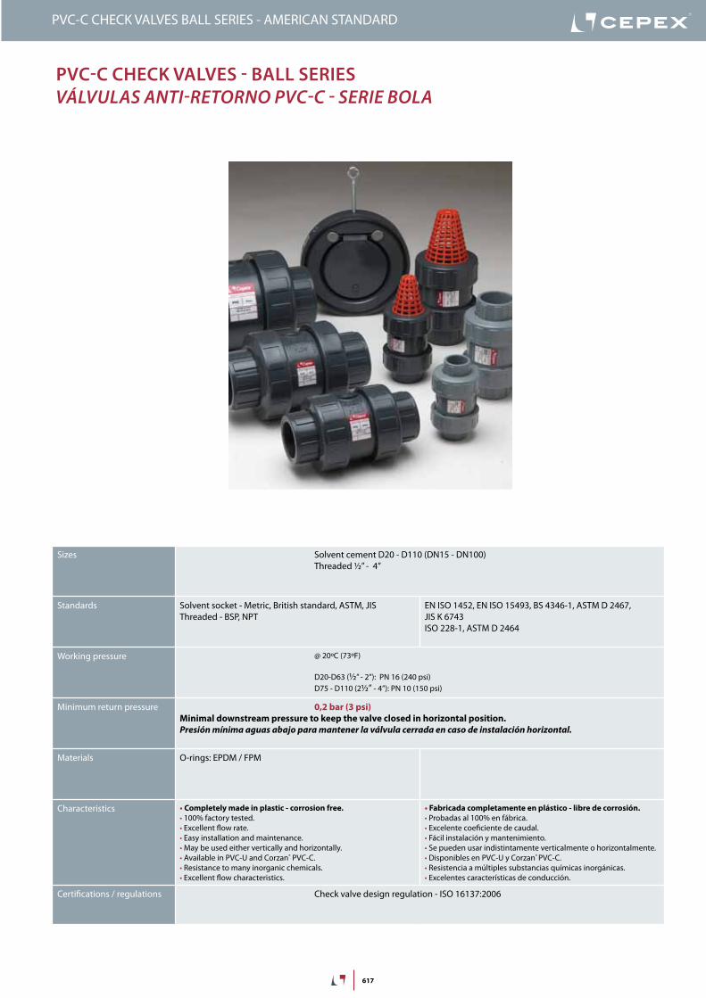
617
PVC-C CHeCk ValVes - Ball series VálVulas aNTi-reTorNo PVC-C - serie bola
PVC-C CHECK VALVES BALL SERIES - AMERICAN STANDARD
Sizes Solvent cement D20 - D110 (DN15 - DN100)Threaded ½” - 4”
Standards Solvent socket - Metric, British standard, ASTM, JISThreaded - BSP, NPT
EN ISO 1452, EN ISO 15493, BS 4346-1, ASTM D 2467, JIS K 6743ISO 228-1, ASTM D 2464
Working pressure @ 20ºC (73ºF)
D20-D63 (½” - 2”): PN 16 (240 psi)D75 - D110 (2½” - 4”): PN 10 (150 psi)
Minimum return pressure 0,2 bar (3 psi)Minimal downstream pressure to keep the valve closed in horizontal position.Presión mínima aguas abajo para mantener la válvula cerrada en caso de instalación horizontal.
Materials O-rings: EPDM / FPM
Characteristics • Completely made in plastic - corrosion free.• 100% factory tested.• Excellent flow rate.• Easy installation and maintenance.• May be used either vertically and horizontally.• Available in PVC-U and Corzan® PVC-C.• Resistance to many inorganic chemicals.• Excellent flow characteristics.
• Fabricada completamente en plástico - libre de corrosión.• Probadas al 100% en fábrica.• Excelente coeficiente de caudal.• Fácil instalación y mantenimiento.• Se pueden usar indistintamente verticalmente o horizontalmente.• Disponibles en PVC-U y Corzan® PVC-C.• Resistencia a múltiples substancias químicas inorgánicas.• Excelentes características de conducción.
Certifications / regulations Check valve design regulation - ISO 16137:2006

618
PVC-C CHECK VALVES BALL SERIES - AMERICAN STANDARD
FIG. Parts Despiece Material
1 Body Cuerpo PVC-C
3 Ball Bola PVC-C
4 Union nut Tuerca PVC-C
5 End connector Manguito enlace PVC-C
6 Closing ring Anillo de cierre PVC-C
7 Body o-ring Junta cuerpo EPDM / FPM
8 End connector o-ring Junta manguito EPDM / FPM
9 Seal-carrier Portajuntas PVC-C
14
7
9
58
3
6
4
5
PressUre / TeMPeraTUre GraPHdiaGraMa PresiÓN / TeMPeraTura
PN 16
PN 10
Pres
sure
/ Pr
esió
n
Temperature / Temperatura
Vida útil: 25 añosPresión hidrostática máxima que un com-ponente es capaz de soportar en servicio continuo (sin sobrepresión)
Life: 25 yearsHydrostatic maximum pressure a comp-nent may outstand in continous service (without overpressure)

619
PVC-C CHECK VALVES BALL SERIES - AMERICAN STANDARD
OpenAbierto
ClosedCerrado
Temperature / Température / Temperatura / Temperatura
20 years / water flow20 années / fluide de l�eau20 años / fluido de agua20 anos / caudal de água
Pres
sure
/Pre
ssio
n/ P
resió
n/ P
ress
ão
18
16
14
12
10
8
6
4
2
0
0 10 20 30 40 50 60 70 80 90 °C32 50 68 86 104 122 140 158 176 194 °F
barpsi
PVC -U
PVC -C
270
240
210
180
150
120
90
60
30
0
PN 16 (240 psi)
PN 10 (150 psi)
Pres
sure
loss
/ Per
tede
char
ge/
Pérd
ida
deca
rga
/ Per
das d
eca
rga
Flow / Débit / Caudal / Caudal
100 1.000 10.000
1
mca
(l/min)
10
26,4 264 2.642 (GPM)
1,5
psi
15
10D20
-½
”
D25
-¾
”D32
-1”
D40
-1¼
”
D50
-1½
”
D63
-2”
D75
-2½
”
D90
-3”
0
relaTiVe FlOWFluJo relaTiVo
D 20-½” 25-¾” 32-1” 40-1¼” 50-1½” 63-2” 75-2½” 90-3”
DN 15 20 25 32 40 50 65 80
Kv100 99 128 308 453 795 1040 1932 2754
Cv 7 9 22 32 56 73 135 193
PressUre lOss DiaGraMdiaGraMa de PÉrdidas de CarGa
Pres
sure
loss
/ Pé
rdid
a de
carg
a
Flow / Caudal
Cv = Kv100 / 14,28Kv100 (l/min, ∆p = 1 bar)Cv (GPM, ∆p = 1 psi)

620
PVC-C CHECK VALVES BALL SERIES - AMERICAN STANDARD
insTrUCCiOnes De MOnTaje
Uniones encoladas o roscadasAfloje las tuercas (4) de la válvula y sepárelas de los manguitos (5). Introduzca las tuercas en los tubos y a continuación fije los manguitos en los extremos del tubo. Las uniones encoladas se realizarán con un adhesivo para tubos de PVC-U o PVC-C rígido y no se aplicará presión hasta transcurridas al menos 1 hora por bar. En las uniones roscadas se colocará cinta de PTFE en las roscas macho. A continuación ya podrá colocarse la válvula entre los manguitos y apretar a mano las tuercas sobre la válvula.
asseMBly insTrUCTiOns
Solvent socket or threaded unionsLoosen the valve union nuts (4) and separate these and the end connectors (5) from the valve body. Pass the pipe through the nuts and then place the bushes over the end of the pipe. The socket unions should be guied onto the pipe using a PVC-U or PVC-C adhesive and pressure should not be applied to the system until a drying period of at least 1 hour per bar of working pressure has elapsed. In the case of threaded unions, PTFE tape should be applied to the male threads. The pipes can now be attached to the valve by hand tightening down the nuts.
1
2
3
4
5

621
D DN PN REF. CODE½” 15 16 35 67 801 ED 27380
¾” 20 16 35 67 802 ED 27381
1” 25 16 35 67 803 ED 27382
1¼” 32 16 35 67 804 ED 27383
1½” 40 16 35 67 805 ED 27384
2” 50 16 35 67 806 ED 27385
2½” 65 10 35 67 907 EMA 27397
3” 80 10 35 67 908 EMA 27398
4” 80 10 35 67 910 EMA 27433
L H E16 84 52
19 108 62
22 119 70
26 142 84
31 162 94
38 192 117
44 232 148
51 269 179
51 269 179
G DN PN REF. CODE½” 15 16 35 67 801 ED 27380
¾” 20 16 35 67 802 ED 27381
1” 25 16 35 67 803 ED 27382
1¼” 32 16 35 67 804 ED 27383
1½” 40 16 35 67 805 ED 27384
2” 50 16 35 67 806 ED 27385
2½” 65 10 35 67 807 E 27392
3” 80 10 35 67 808 E 27393
4” 80 10 35 67 810 E 27432
L H E16 84 52
19 108 62
22 119 70
26 142 84
31 162 94
38 192 117
44 232 148
51 269 179
51 269 179
G
LL
E
H
D
LL
EH
Válvula anti-retorno de bola• Cuerpo en Corzan® PVC-C• Encolar hembra• Serie ASTM• Anillos tóricos en EPDM
Ball check valve• Corzan® PVC-C body• Female solvent socket• ASTM series• O-Rings in EPDM
CP-B. 67. SF1. MA - PVC-C BALL CHECK VALVE
Válvula anti-retorno de bola• Cuerpo en Corzan® PVC-C• Roscar hembra NPT• Anillos tóricos en EPDM
Ball check valve• Corzan® PVC-C body• NPT female thread• O-Rings in EPDM
CP-B. 67. FT1. MA - PVC-C BALL CHECK VALVE
VERSIÓN COMBO
• 1½” - 2”: manguitos enlace encolar montados + mangui-tos enlace roscar añadidos en caja• 2½” - 4”: sólo manguitos enlace encolar o roscar
Todos los modelos incluyen rejilla para transformación en válvula de pie
PVC-C CHECK VALVES BALL SERIES - AMERICAN STANDARD
COMBO VERSION
• 1½” - 2”: valve with solvent socket unions + spare threadedunions in the same box• 2½” - 4”: only solvent sokcet or threaded unions assem-bled
All the models including the grid for transforming the checkvalve in foot valve
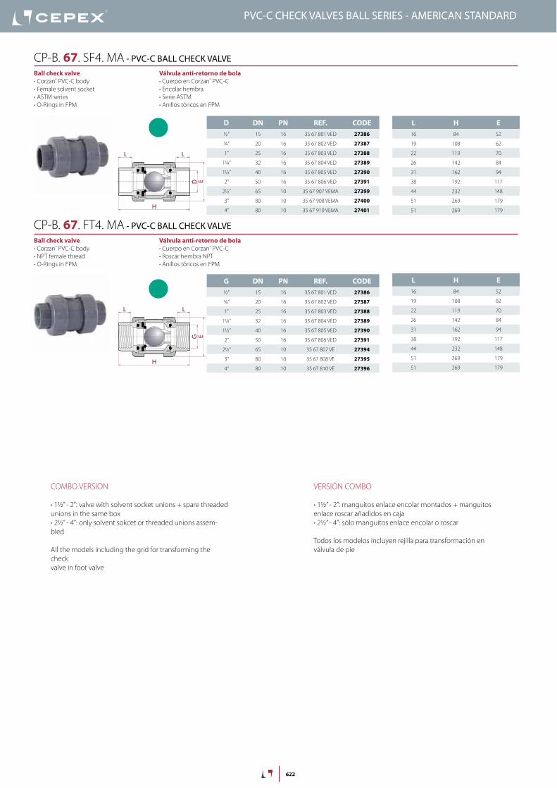
622
VERSIÓN COMBO
• 1½” - 2”: manguitos enlace encolar montados + manguitos enlace roscar añadidos en caja• 2½” - 4”: sólo manguitos enlace encolar o roscar
Todos los modelos incluyen rejilla para transformación en válvula de pie
D DN PN REF. CODE½” 15 16 35 67 801 VED 27386
¾” 20 16 35 67 802 VED 27387
1” 25 16 35 67 803 VED 27388
1¼” 32 16 35 67 804 VED 27389
1½” 40 16 35 67 805 VED 27390
2” 50 16 35 67 806 VED 27391
2½” 65 10 35 67 907 VEMA 27399
3” 80 10 35 67 908 VEMA 27400
4” 80 10 35 67 910 VEMA 27401
L H E16 84 52
19 108 62
22 119 70
26 142 84
31 162 94
38 192 117
44 232 148
51 269 179
51 269 179
G DN PN REF. CODE½” 15 16 35 67 801 VED 27386
¾” 20 16 35 67 802 VED 27387
1” 25 16 35 67 803 VED 27388
1¼” 32 16 35 67 804 VED 27389
1½” 40 16 35 67 805 VED 27390
2” 50 16 35 67 806 VED 27391
2½” 65 10 35 67 807 VE 27394
3” 80 10 35 67 808 VE 27395
4” 80 10 35 67 810 VE 27396
L H E16 84 52
19 108 62
22 119 70
26 142 84
31 162 94
38 192 117
44 232 148
51 269 179
51 269 179
G
LL
E
H
D
LL
E
H
Válvula anti-retorno de bola• Cuerpo en Corzan® PVC-C• Encolar hembra• Serie ASTM• Anillos tóricos en FPM
Ball check valve• Corzan® PVC-C body• Female solvent socket• ASTM series• O-Rings in FPM
CP-B. 67. SF4. MA - PVC-C BALL CHECK VALVE
Válvula anti-retorno de bola• Cuerpo en Corzan® PVC-C• Roscar hembra NPT• Anillos tóricos en FPM
Ball check valve• Corzan® PVC-C body• NPT female thread• O-Rings in FPM
CP-B. 67. FT4. MA - PVC-C BALL CHECK VALVE
PVC-C CHECK VALVES BALL SERIES - AMERICAN STANDARD
COMBO VERSION
• 1½” - 2”: valve with solvent socket unions + spare threadedunions in the same box• 2½” - 4”: only solvent sokcet or threaded unions assem-bled
All the models including the grid for transforming the checkvalve in foot valve